Embed Size (px)
Citation preview
5
Fuzzy PID Supervision for an Automotive Application: Design and Implementation
R. Sehab and B. Barbedette Ecole Supérieure des Techniques Aéronautiques et de Construction Automobile
France
1. Introduction
In the control of plants with good performances, engineers are often faced to design
controllers in order to improve static and dynamic behavior of plants. Usually the
improvement of performances is observed on the system responses. For illustration, an
example of a DC machine is chosen. Two cases of study are presented:
1. In open loop, the velocity response depends on the mechanical time constant of the DC machine (time response) and the value of the power supply. Indeed, for each value of power supply, a velocity value is reached in steady state. Therefore the DC machine can reach any value of velocity which depends only of the power supply. In this case no possibility to improve performances.
2. For a specific need, the open loop control is not sufficient. Engineers are faced to a problem of control in order to reach a desired velocity response according to defined specifications such as disturbance rejection, insensitivity to the variation of the plant parameters, stability for any operation point, fast rise-time, minimum Settling time, minimum overshoot and a steady state error null. Also, the designed control is related to other constraints related to the cost, computation complexity, manufacturability, reliability, adaptability, understandability and politics (Passino & Yurkovich, 1998).
In general the design of the control needs to identify the dynamic behavior of the system.
Therefore a dynamic model of the plant is developed in order to reproduce the real response
in open loop. Developing a model for a plant is a complex task which needs time and an
intuitive understanding of the plant’s dynamics. Usually, on the basis of some assumptions
to choose, a simplified model is developed and the physical parameters of the established
model are identified using some experimental responses. If the model is nonlinear, we need
to linearize the model around a steady state point in order to get a simplified linear model.
Therefore a linear controller is designed with techniques from classical control such as pole
placement or frequency domain methods. Using the mathematical model and the designed
controller, a simulation in closed loop is carried out in order to study and to analyze its
performances. This step of study consists to adjust controller parameters until performances
are reached for a given set point. In the last step, the designed controller is implemented via,
for example, a microprocessor, and evaluating the performance of the closed-loop system
(again, possibly leading to redesign).
www.intechopen.com

PID Controller Design Approaches – Theory, Tuning and Application to Frontier Areas
102
In industry most time engineers are interested by linear controllers such as proportional-
integral-derivative (PID) control or state controllers. Over 90% of the controllers in operation
today are PID controllers (or at least some form of PID controller like a P or PI controller).
This approach is often viewed as simple, reliable, and easy to understand and to implement
on PLCs. Also performances of the plant are on-line improved by adjusting only gains. In
spite of the advantages of PID controllers, the process performances are never reached. This
is due mainly to the accuracy of the model used to design controller and not properly to the
controller.
In the development of analytical models, variation of physical parameters, operation
conditions, disturbances are not taken into account. This is due to the difficulty to identify
all the physical phenomena in the process and to find an appropriate model for each.
Therefore the closed loop specifications of the process are not maintained. Engineers are
however in the need to adjust permanently PID controllers even it’s a heavy task. For these
different reasons, a new approach of control is proposed taking into account the constraints
related to the process, the parameter variation and disturbances. This type of control, named
fuzzy control, is designed from the operator experience on the process over many years.
Under different operation conditions, linguistic rules are established taking into account
constraints and environment process. In this case, modeling the process is not necessary and
the designed fuzzy controller is sufficient to ensure the desired performances. In other cases,
if the model is known with a good accuracy, industrials prefer to implement a fuzzy PID
supervisor to their existing PID controllers where gains are on-line adjusted taking into
account different operation conditions, variation of plant parameters and disturbances.
Using this type of control, performances are better in comparison to PID controllers and no
need to adjust on-line the PID parameters. Currently, Fuzzy control has been used in a wide
variety of applications in engineering, science, business, medicine, psychology, and other
fields (Passino & Yurkovich, 1998). For instance, in engineering some potential application
areas include the following:
1. Aircraft/spacecraft: Flight control, engine control, avionics systems, failure diagnosis, navigation, and satellite attitude control.
2. Automated highway systems: Automatic steering, braking, and throttle control for vehicles.
3. Automobiles: Brakes, transmission, suspension, and engine control. 4. Autonomous vehicles: Ground and underwater. 5. Manufacturing systems: Scheduling and deposition process control. 6. Power industry: Motor control, power control/distribution, and load estimation. 7. Process control: Temperature, pressure, and level control, failure diagnosis, distillation
column control, and desalination processes. 8. Robotics: Position control and path planning.
In this chapter, a brief description of fuzzy control is given in order to understand how to design a fuzzy controller. Among the different type of fuzzy controllers, a Fuzzy PID supervision associated to a PID control is presented using different approaches. Also a new approach based a non linear model is proposed to design a fuzzy PID supervisor where performances are a priori defined and taken into. Finally, an automotive application is chosen for illustration and validation of the proposed approach. For a steer-by-wire a fuzzy
www.intechopen.com

Fuzzy PID Supervision for an Automotive Application: Design and Implementation
103
PD supervisor is designed and a comparison of performances is carried out with a PID control.
2. Fuzzy control
Fuzzy control is useful in some cases where the control processes are too complex to analyze by conventional quantitative techniques. Fuzzy control design is very interesting for industrial processes where modeling is not easy to make or conception of nonlinear controllers for industrial processes with models. The available sources of information of a process are interpreted qualitatively, inexactly or uncertainly. The main advantages of fuzzy logic control remains in (Passino & Yurkovich, 1998):
1. Parallel or distributed multiple fuzzy rules –complex nonlinear 2. Linguistic control, linguistic terms –human knowledge 3. Robust control
3. Fuzzy control system design
Figure 1 gives the fuzzy controller block diagram, where we show a fuzzy controller embedded in a closed-loop control system. The plant outputs are denoted by y(t), its inputs are denoted by u(t), and the reference input to the fuzzy controller is denoted by r(t). The design of fuzzy logic controller is based on four main components (Passino & Yurkovich, 1998):
1. The fuzzification interface which transforms input crisp values to fuzzy values 2. The knowledge base which contains a knowledge of the application domain and the
control objectives 3. The decision-making logic which performs inference for fuzzy control actions 4. The defuzzification interface which provides the control signal to the process
Fig. 1. Fuzzy controller diagram
3.1 Fuzzification
The fuzzification block contains generally preliminary data which are obtained from:
- Conversion of measured variables with analog/digital converters - Preprocessing of the measured variables in order to get the state, error, state error
derivation and state error integral of the variables to control (output variables or other state variables).
www.intechopen.com
PID Controller Design Approaches – Theory, Tuning and Application to Frontier Areas
104
- Choice of membership functions for the input and output variables namely the shape, the number and distribution. Usually three to five triangular or Gaussian membership functions are used with a uniform distribution presenting 50% of overlapping. More than seven membership functions, the algorithm processing becomes long and presents a drawback for fast industrial processes.
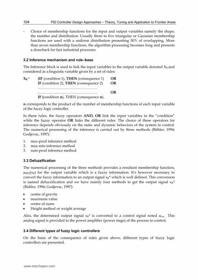
3.2 Inference mechanism and rule–base
The Inference block is used to link the input variables to the output variable denoted XR and considered as a linguistic variable given by a set of rules:
XR = (IF (condition 1), THEN (consequence 1) OR
IF (condition 2), THEN (consequence 2) OR ………………………………………… ………………………………………… OR IF (condition n), THEN (consequence n).
n corresponds to the product of the number of membership functions of each input variable of the fuzzy logic controller.
In these rules, the fuzzy operators AND, OR link the input variables in the “condition” while the fuzzy operator OR links the different rules. The choice of these operators for inference depends obviously on the static and dynamic behaviors of the system to control. The numerical processing of the inference is carried out by three methods (Bühler, 1994; Godjevac, 1997):
1. max-prod inference method 2. max-min inference method 3. sum-prod inference method
3.3 Defuzzification
The numerical processing of the three methods provides a resultant membership function,
µRES(xR) for the output variable which is a fuzzy information. It’s however necessary to
convert the fuzzy information to an output signal xR* which is well defined. This conversion
is named defuzzification and we have mainly four methods to get the output signal xR*
(Bühler, 1994; Godjevac, 1997):
centre of gravity
maximum value
centre of sums
Height method or weight average
Also, the determined output signal xR* is converted to a control signal noted ucm . This
analog signal is provided to the power amplifier (power stage) of the process to control.
3.4 Different types of fuzzy logic controllers
On the basis of the consequence of rules given above, different types of fuzzy logic controllers are presented.
www.intechopen.com
Fuzzy PID Supervision for an Automotive Application: Design and Implementation
105
1. If the consequence is a membership function or a fuzzy set, the fuzzy controller is Mamdani type. In this case, the processing of inference uses often the max-min or max-prod inference method while for defuzzification, the center of gravity method is often used and in some cases we use the maximum value method if fast control is needed.
2. If the consequence is a linear combination of the input variables of the fuzzy logic controller. Indeed each rule corresponds to a local linear controller around a steady state. Consequently, the set of the established rules correspond to a nonlinear controller. In this case, we use max-min or max-prod inference method and for deffuzification, we often use the weight average method.
Also, it exists other types of fuzzy logic controllers such as Larsen or Tsukamoto (Driankov et al., 1993). Most of time Mamadani and TSK controllers are used in the design of controllers for nonlinear systems with or without models (Bühler, 1994; Godjevac, 1997; Nguyen, 1997).
The advantages of the design of a fuzzy logic controller using Mamdani type are an intuitive method, used at a big scale and well suited for translation of human experience on linguistic rules.
On the other hand, the advantages of a fuzzy logic controller using a Takagi-Sugeno type are:
1. Good operation with linear techniques (the consequence of a rule is linear) 2. Good operation with optimization techniques and parameters adaptation of a controller 3. Continuous transfer characteristics 4. very suited for systems with a model 5. fast processing of information
3.5 Discussion
The different steps followed in the processing of the input variables of the fuzzy logic
controller namely fuzzification, inference and defuzzification, allows to get a non linear
characteristic. Indeed it’s an advantage when compared to the classical control. The
nonlinearity of this characteristic depends on some parameters. For example the number,
the type and the distribution of membership functions. Also, other parameters can be
considered such as the number of rules and inference methods. Finally, the nonlinearity can
be more or less pronounced depending on all these parameters.
In this case we consider the fuzzy logic controller as a nonlinear controller. Another
possibility to get a non linear controller is to design and to add a fuzzy supervision to a PID
controller. Industrials are motivated to keep PID controllers which are well known and to
add a fuzzy supervisor which modifies on-line PID parameters in order to reach and to
maintain high performances whatever the parameters change and operations conditions
maybe. In the design of the fuzzy supervision, the outputs are the PID parameters to
provide on-line to the PID controller.
4. Fuzzy supervisory control
Fuzzy Supervisory controller is a multilayer (hierarchical) controller with the supervisor at the highest level, as shown in Figure 2. The fuzzy supervisor can use any available data
www.intechopen.com

PID Controller Design Approaches – Theory, Tuning and Application to Frontier Areas
106
from the control system to characterize the system’s current behavior so that it knows how to change the controller and ultimately achieve the desired specifications. In addition, the supervisor can be used to integrate other information into the control decision-making process.
Fig. 2. Fuzzy Supervisory controller
Conceptually, the design of the supervisory controller can then proceed in the same manner
as it did for direct fuzzy controllers (fuzzification, inference and defuzzification): either via
the gathering of heuristic control knowledge or via training data that we gather from an
experiment. The form of the knowledge or data is, however, somewhat different than in the
simple fuzzy control problem. For instance, the type of heuristic knowledge that is used in a
supervisor may take one of the following two forms:
1. Information from a human control system operator who observes the behavior of an existing control system (often a conventional control system) and knows how this controller should be tuned under various operating conditions.
2. Information gathered by a control engineer who knows that under different operating conditions controller parameters should be tuned according to certain rules.
Fuzzy supervisor is characterized by:
1. The outputs which are not control signals to provide to the control system but they are parameters to provide to the controller in order to compute the appropriate control.
2. Fuzzy supervision associated to the controller can be considered as an adaptatif controller
3. Fuzzy supervisor can integrate different types of information to resolve problems of control.
4.1 Supervision of conventional controllers
Most controllers in operation today have been developed using conventional control
methods. There are, however, many situations where these controllers are not properly
tuned and there is heuristic knowledge available on how to tune them while they are in
operation. There is then the opportunity to utilize fuzzy control methods as the supervisor
that tunes or coordinates the application of conventional controllers. In this part,
supervision of conventional controllers concerns only PID controllers and how the
supervisor can act as a gain scheduler
www.intechopen.com

Fuzzy PID Supervision for an Automotive Application: Design and Implementation
107
4.2 Fuzzy tuning of PID controllers
Over 90% of the controllers in operation today are PID controllers. This is because PID controllers are easy to understand, easy to explain to others, and easy to implement. Moreover, they are often available at little extra cost since they are often incorporated into the programmable logic controllers (PLCs) that are used to control many industrial processes. Unfortunately, many of the PID loops that are in operation today are in continual need of monitoring and adjustment since they can easily become improperly tuned.
Because PID controllers are often not properly tuned (e.g., due to plant parameter variations or operating condition changes), there is a significant need to develop methods for the automatic tuning of PID controllers for nonlinear systems where the model is not well known. In this method, the fuzzy supervisor knows, from a response time, when the controller is not well tuned and acts by adjusting the controller gains in order to improve system performances. The principle scheme of the fuzzy PID auto tuner (Passino & Yurkovich, 1998) is given by figure 3.
Fig. 3. Fuzzy PID auto-tuner
The block “Behavior Recognition” is used to characterize and analyze the current response of the system and provides information to the “PID Designer” in order to determine the new parameters of the PID controllers and to improve performances. The basic form of a PID controller is given by:
tP I D
0
du(t)=K e(t)+K e(τ)dτ+K e(t)
dt (1)
Where u is the control signal provided by the PID controller to the plant. e: the error deuced from the reference input r and the plant output y. Kp is the proportional gain, Ki is the integral gain, and Kd is the derivative gain.
In this case, the adjustment of PID parameters is carried out by some candidate rules as follows:
www.intechopen.com

PID Controller Design Approaches – Theory, Tuning and Application to Frontier Areas
108
If steady-state error is large Then increase the proportional gain.
If the response is oscillatory Then increase the derivative gain.
If the response is sluggish Then increase the proportional gain.
If the steady-state error is too big Then adjust the integral gain.
If the overshoot is too big then decrease the proportional gain.
In these rules conditions are deal with the block «Behavior Recognition" and consequences are evaluated by the block “PID Designer” of the fuzzy supervisor. In some applications controller gains are quantified according to different types of responses a priori identified from experiments on the real process and implemented on the block “Behavior Recognition” (Passino & Yurkovich, 1998).
4.3 Fuzzy gain scheduling
Conventional gain scheduling involves using extra information from the plant, environment, or users to tune (via “schedules”) the gains of a controller. The overall scheme is shown in Figure 4. A gain schedule is simply an interpolator that takes as inputs the operating condition and provides values of the gains as its outputs. One way to construct this interpolator is to view the data associations between operating conditions and controller gains.
Fig. 4. Conventional fuzzy gain scheduler
The controller gains are established on the basis of information collected from the plant to control, the operator or the environment. Three approaches are proposed for the construction of the fuzzy gain scheduling (Passino & Yurkovich, 1998) :
Heuristic Gain Schedule Construction
Construction of gain schedule by fuzzy identification
Construction of gain schedule using the PDC method (Parallel Distributed Compensation method)
4.3.1 Construction of an heuristic schedule gain
This method is applied for plants with specific particularities not involved in the design of classical controllers. The PID parameters are deduced intuitively and the rules used for the adjustment of parameters are heuristic. This is for example the case of a tank with an oval shape (figure 5). In the heuristic rules, the condition corresponds to the water levels and the consequence corresponds to the values of the controller gain (Passino & Yurkovich, 1998).
www.intechopen.com

Fuzzy PID Supervision for an Automotive Application: Design and Implementation
109
Each rule covers a set of water levels taking into account the tank section. For low levels, the gain is higher in order to get high flow rates and for high water levels, the gain is small in order to get small flow rates. This approach is very useful for systems without models.
Fig. 5. Tank
4.3.2 Construction of a schedule gain by fuzzy identification
This approach is useful for plants where we know a priori how to adjust the controller gains
under different operation conditions (Passino & Yurkovich, 1998). For example if a control
engineer knows how to adjust gain controller according to certain rules, he can represent
this data by a fuzzy model of Mamdani or TSK type. Indeed it’s the equivalent of a set of
controllers which are active in terms of the operation points. Also, the gain controllers are
deduced on-line by the inference mechanism between controllers for any operation point.
Indeed it’s a soft transition from controller to another one.
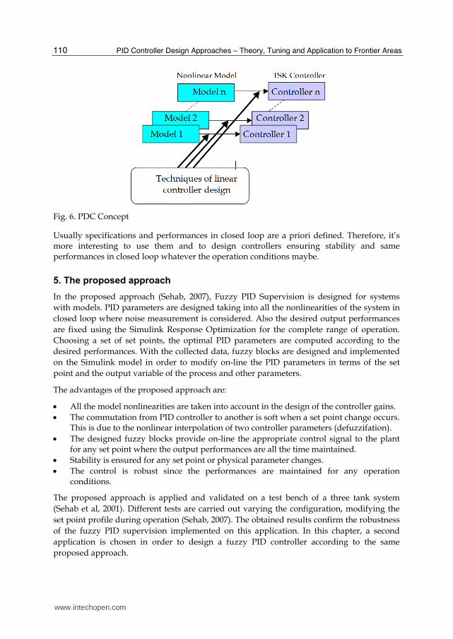
4.3.3 Construction of a gain schedule using the PDC method
This approach is applied particularly for processes that can be modelled. Most of time, the
established models are nonlinear. In this case, the nonlinear model is replaced by a sum of
linearized models around different operation points (Passino & Yurkovich, 1998),
(Vermeiren, 1998). For each linearised model, a linear controller is designed (figure 6). These
linear controllers could be PI, PID, PD ou state controllers. The set of the designed
controllers is finally a non linear controller which is a fuzzy controller.
In this approach the n linearized models and the n corresponding controllers are rules
which are active simultaneously two by two since the condition is similar for both, thus the
name of the method "Parallel Distributed Compensation”.
In all the approaches presented above, performances are not used directly when designing
controllers. Also non linearities, disturbances and variation parameters of the plant are not
taken into account in the systems with models.
In some cases stability is not ensured particularly when a change set point occurs or when a
disturbance is present. In the case of the PDC approach, local and global stabilities are
checked using Lyapunov theory (Passino & Yurkovich, 1998). For the other approaches,
stability is checked when implementing fuzzy supervision for classical controllers.
www.intechopen.com
PID Controller Design Approaches – Theory, Tuning and Application to Frontier Areas
110
Fig. 6. PDC Concept
Usually specifications and performances in closed loop are a priori defined. Therefore, it’s more interesting to use them and to design controllers ensuring stability and same performances in closed loop whatever the operation conditions maybe.
5. The proposed approach
In the proposed approach (Sehab, 2007), Fuzzy PID Supervision is designed for systems
with models. PID parameters are designed taking into all the nonlinearities of the system in
closed loop where noise measurement is considered. Also the desired output performances
are fixed using the Simulink Response Optimization for the complete range of operation.
Choosing a set of set points, the optimal PID parameters are computed according to the
desired performances. With the collected data, fuzzy blocks are designed and implemented
on the Simulink model in order to modify on-line the PID parameters in terms of the set
point and the output variable of the process and other parameters.
The advantages of the proposed approach are:
All the model nonlinearities are taken into account in the design of the controller gains.
The commutation from PID controller to another is soft when a set point change occurs. This is due to the nonlinear interpolation of two controller parameters (defuzzifation).
The designed fuzzy blocks provide on-line the appropriate control signal to the plant for any set point where the output performances are all the time maintained.
Stability is ensured for any set point or physical parameter changes.
The control is robust since the performances are maintained for any operation conditions.
The proposed approach is applied and validated on a test bench of a three tank system
(Sehab et al, 2001). Different tests are carried out varying the configuration, modifying the
set point profile during operation (Sehab, 2007). The obtained results confirm the robustness
of the fuzzy PID supervision implemented on this application. In this chapter, a second
application is chosen in order to design a fuzzy PID controller according to the same
proposed approach.
www.intechopen.com

Fuzzy PID Supervision for an Automotive Application: Design and Implementation
111
In automotive, many systems are integrated in vehicle in order to ensure continuously the driver comfort and the safety during driving. Among them, the active suspension, antibraking system (ABS), electronic stability program (EPS) and steer by wire SBW). In our case, the steer by wire is chosen for this study. Some works on “steering by wire” using fuzzy control were realized. The interest of using fuzzy techniques consisted to treat the global non-linearity of this device. For example, fuzzy controller improved the vehicle’s stability at different speeds (Shu et al., 2011). An hybrid-fuzzy controller combining a conventional PID and a fuzzy controller together were developed (Qu et al. 2010). This controller gave results showing quick responses and little overshoot like conventional steering device.
6. System description
Steer-By-Wire (SBW) System (Figure 7) is a new design which eliminates the mechanical link
between the handwheel and the roadwheel. The measured handwheel position controls the
roadwheel position using an electrical motor (road motor). However, the driver has to feel
the feedback road force as in the case of a classical steering. For sensing this force, a sensor
torque is added in order to control a second electrical motor (Feedback motor). The
associated inputs and outputs of motors are managed by an Electronic Control Unit (ECU).
The road motor and the feedback motor are respectively controlled in angular position and
torque by P and PI controllers. Both are implemented in the ECU.
Fig. 7. Steer-by-Wire System
www.intechopen.com
PID Controller Design Approaches – Theory, Tuning and Application to Frontier Areas
112
7. System modeling
In the system given by figure 7, different subsystems are considered. The modeling of each subsystem of the steer by wire is described in the following paragraphs.
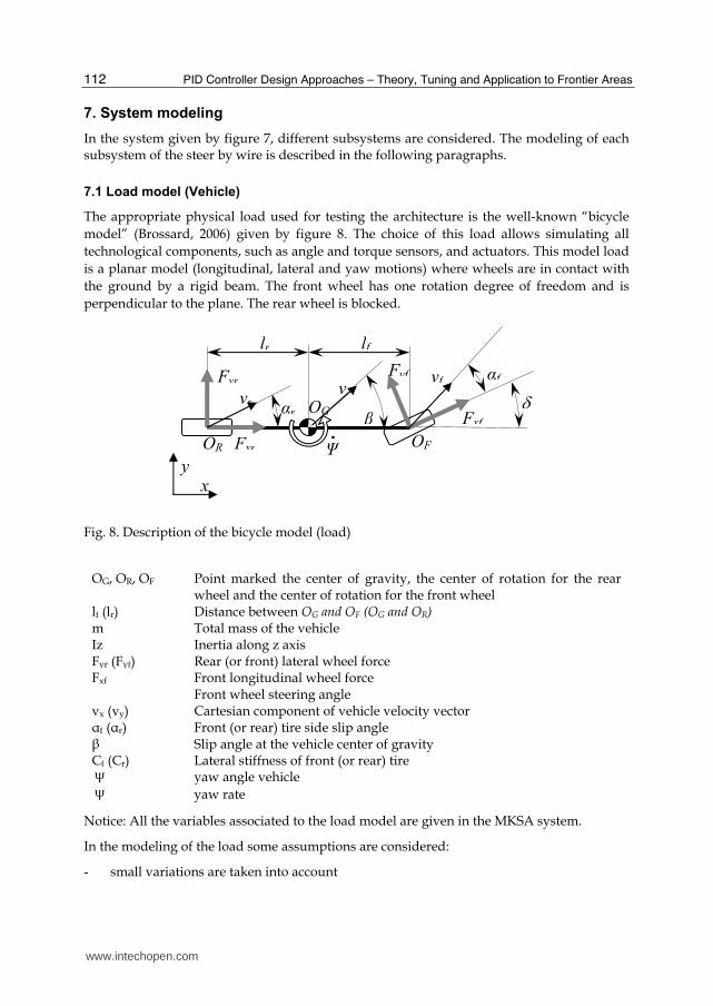
7.1 Load model (Vehicle)
The appropriate physical load used for testing the architecture is the well-known “bicycle
model” (Brossard, 2006) given by figure 8. The choice of this load allows simulating all
technological components, such as angle and torque sensors, and actuators. This model load
is a planar model (longitudinal, lateral and yaw motions) where wheels are in contact with
the ground by a rigid beam. The front wheel has one rotation degree of freedom and is
perpendicular to the plane. The rear wheel is blocked.
Fig. 8. Description of the bicycle model (load)
OG, OR, OF Point marked the center of gravity, the center of rotation for the rear
wheel and the center of rotation for the front wheel lf (lr) Distance between OG and OF (OG and OR) m Total mass of the vehicle Iz Inertia along z axis Fyr (Fyf) Rear (or front) lateral wheel force Fxf Front longitudinal wheel force Front wheel steering angle vx (vy) Cartesian component of vehicle velocity vector f (r) Front (or rear) tire side slip angle Slip angle at the vehicle center of gravity Cf (Cr) Lateral stiffness of front (or rear) tire yaw angle vehicle yaw rate
Notice: All the variables associated to the load model are given in the MKSA system.
In the modeling of the load some assumptions are considered:
- small variations are taken into account
x y
lr lf
αf
Fyr
Fxr
Fyf
Fxf
vf
vr
β
Ψ
αr OG
OR OF
v
www.intechopen.com

Fuzzy PID Supervision for an Automotive Application: Design and Implementation
113
- the longitudinal velocity is constant - the vehicle doesn’t slip
According to figure 8, the mechanical dynamic equations are given by:
˙
xf yr y xcosδ F sinδ F m v v yfF (2)
f yf r xf yr zl F cosδ l F sinδ F I (3)
Including the non-holomic kinematic constraints, the slip angles of the tires are given as:
y f1
fx
v l tan δ
v
(4)
y r1
rx
v l tan
v
(5)
Considering the force generated by the wheels as linearly proportional to the slip angle, the lateral forces are defined as:
yf f fF C (6)
yr r rF C (7)
The whole of those equations gives the model of the vehicle where the front wheel steering
angle is the input and the yaw rate is the primary output. With this output, the lateral forces
are deduced.
7.2 DC motor models
The DC motor model is valid for feedback and road motors of the Steer by Wire system
given by figure 1.The electrical equation is given by:
di
U R.i L edt
(8)
where:
R, L are respectively the armature resistance (Ω) and inductance (H) i: armature current (A) e: back e.m.f (V)
Also, the mechanical equation is given by:
m m friction loadJ . T T T (9)
Jm: motor inertia (kgm2)
www.intechopen.com
PID Controller Design Approaches – Theory, Tuning and Application to Frontier Areas
114
: motor rotary velocity(rd/s) Tm: motor torque (Nm) Tfriction: friction torque (Nm) Tload: load torque (Nm)
The friction torque is defined by the resultant of viscous and dry frictions:
m m friction loadJ . T T T (10)
Also, motor torque and back e.m.f are given by:
e k. (11)
mT k.i (12)
k: the back e.m.f coefficient (Nm/A)
7.3 Rack/pinion model
The rack and pinion converts a linear displacement to an angle or a torque to a force. This transformation respects a ratio corresponding to the primitive radius R of the pinion. As the frictions (no backlash and no slide) are neglected, the corresponding equations are given by:
V R. (13)
.mT R F (14)
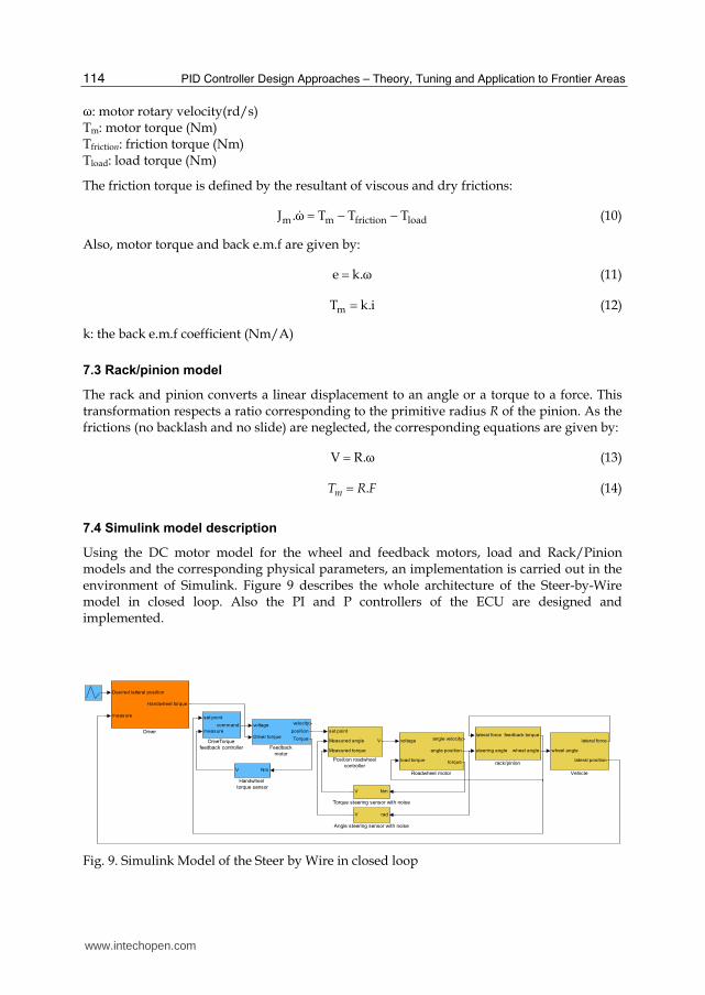
7.4 Simulink model description
Using the DC motor model for the wheel and feedback motors, load and Rack/Pinion models and the corresponding physical parameters, an implementation is carried out in the environment of Simulink. Figure 9 describes the whole architecture of the Steer-by-Wire model in closed loop. Also the PI and P controllers of the ECU are designed and implemented.
lateral force
steering angle
feedback torque
wheel angle
rack/pinion
wheel angle
lateral force
lateral position
Vehicle
NmV
Torque steering sensor with noise
voltage
load torque
angle velocity
angle position
torque
Roadwheel motor
set point
Measured angle
Measured torque
V
Position roadwheel
controllerNmV
Handwheel
torque sensor
voltage
Driver torque
velocity
position
Torque
Feedback
motor
Desired latteral position
measure
Handwheel torque
Driver
set point
measure
command
DriveTorque
feedback controller
radV
Angle steering sensor with noise
Fig. 9. Simulink Model of the Steer by Wire in closed loop
www.intechopen.com

Fuzzy PID Supervision for an Automotive Application: Design and Implementation
115
In order to reach the desired lateral position, the driver provides the appropriate handwheel
torque according to the vehicle speed. Therefore, a driver model is proposed and
implemented in the Simulink model of the Steer-by-Wire of figure 9. A proportional
derivative controller is however chosen to reproduce the dynamic behavior of the driver.
Indeed no need of the integral part in the controller since in the model, rack/pignon has an
integral behavior.
Also random disturbances are added in the Simulink model for the measured armature
currents (torque sensors) of the handwheed and the roadwheel motors and measured
angular steering as shown in figure 9.
On the basis of the complete Simulink model, the PD parameters are determined for a
chosen lateral position and a given vehicle speed where vehicle reaches the lateral position
with minimum overshoot and time response.
Using the designed controller, a simulation is carried out for other operation points defined
by the lateral position and the vehicle speed chosen by the driver. In all the studied cases,
the performances are not maintained and in other cases system is instable.
Indeed, all the nonlinearities presented in the model involve, in some cases, instability and
in others, degradation of system performances even responses, for some operation points,
are stable. For this reason, it’s interesting to design a Fuzzy PID Supervisor in order to
modify on-line the PD parameters ensuring permanently good performances and stability
whatever the operation conditions maybe.
8. Design procedure of fuzzy PD supervision
According to the proposed approach, the first step to follow is to design PD controller for
each operation point where performances are imposed using optimization response time
toolbox of Matlab. In this case, the chosen performances are minimum response time and
overshoot of the lateral position followed by the vehicle according the lateral position of the
trajectory followed by the driver. The operation ranges are defined by [1.5 - 7] m for the
lateral position and by [0 - 72] km/h for the vehicle speed. These values correspond to the
normal driving ensuring the driver safety. Choosing different set points from the defined
operation ranges, optimal PD parameters are computed. For each case, stability is ensured
but the obtained responses do not satisfy the desired performances at a high level.
On the basis of the collected data (Kp and Td) two fuzzy blocks are conceived using
Mamdani approach of fuzzy logic toolbox of Matlab. The first block provides Kp in terms of
the error on the lateral position and the second provides Td in terms also of the error on the
lateral position. Figure 10 gives the designed fuzzy PD Supervisor which varies on-line the
parameters Kp and Kd of the PD controller. Indeed the Fuzzy PD supervisor associated to the
PD controller is also considered as a fuzzy logic controller. Also, the control signal noted Uc
corresponds to the resistive torque to apply on the hanwheel taking into account the vehicle
speed and the desired lateral position. For a given vehicle speed, the values of Kp and Td are
computed by defuzzification (nonlinear interpolation) from the measured lateral position
(Y) and the chosen set point (YSet point).
www.intechopen.com

PID Controller Design Approaches – Theory, Tuning and Application to Frontier Areas
116
Fig. 10. Fuzzy Controller
9. Implementation and simulation
In the second step of this study, the fuzzy PD supervisor of figure 10 is implemented on the
simulator of the Steer-by-Wire given by figure 9. Choosing a vehicle speed and lateral
position set points from the operation ranges, a simulation is carried out in order to make a
comparison with classical control using the corresponding PD controller.
with classical control
with fuzzy control
Fig. 11. Lateral position
For a lateral position set point and a vehicle speed, figure 11, gives the evolution of the lateral position in case of classical control (figure 11-a) and in case of fuzzy logic control (figure 11-b). Indeed with the fuzzy control the steady state is reached, without overshoot in
www.intechopen.com

Fuzzy PID Supervision for an Automotive Application: Design and Implementation
117
20s, while with classical control, the steady state is reached, with an overshoot, in 35s. Indeed the performances are better with fuzzy control in comparison to the classical control.
Also, for the chosen lateral position y = 7m and a vehicle speed Vveh= 36 km/h, the evolution of torques of the feedback motor are shown in figure 12. Indeed the rack torque is well compensated by the load torque applied by the driver on the handwheel even with fuzzy or classical control. Also, the steady state torque responses are reached in 15 s (Fig. 12-b) when compared to the classical control (Fig.12-a). Indeed this is due to the high value of the load torque applied by the driver in case of fuzzy control during transient time.
0 5 10 15 20 25 30 35 40-0.6
-0.4
-0.2
0
0.2
0.4
0.6
0.8Ysetpoint = 7m; Vveh = 36 km/h
Torq
ues (
Nm
)
time (s)
Rack Torque (Set Point)
Feedback Motor Torque
Load Torque (Driver)
-a- with classical control
0 5 10 15 20 25 30 35 40-0.6
-0.4
-0.2
0
0.2
0.4
0.6
0.8
Ysetpoint = 7m; Vveh = 36 km/h
Torq
ues (
Nm
)
time (s)
Rack Torque (Set Point)
Feedback Motor Torque
Load Torque (Driver)
-b- with fuzzy control
Fig. 12. Torques of the feedback motor
Also in figure 13, the rack angular position is reached with a response time of 15 s (Fig.13-b) in
comparison to the classical control (Fig.13-a). Also, during transient time, the rack angular set
point provided by the handwheel motor, in case of fuzzy control, presents some oscillations
when compared to the same response with classical control. Indeed it’s a drawback due to the
nonlinearity of the vehicle dynamics and eventually variations of PD parameters.
Also for the wheel angle, the steady state is reached in 15s with the same oscillations which
are involved by the rack angular position during the transient time (Fig.14-b) while with the
classical control, the steady state is reached in 25 s with small oscillations during transient
time (Fig.14-a).
www.intechopen.com

PID Controller Design Approaches – Theory, Tuning and Application to Frontier Areas
118
0 5 10 15 20 25 30 35 40-4
-3
-2
-1
0
1
2Ysetpoint = 7m; Vveh = 36 km/h
Ra
ck A
ng
ula
r P
ositio
n(r
d)
time (s)
Measure
Feedback Motor Position (Set Point)
a- with classical control
0 5 10 15 20 25 30 35 40-4
-3
-2
-1
0
1
2Ysetpoint = 7m; Vveh = 36 km/h
time (s)
Ra
ck A
ng
ula
r P
ositio
n (
rd)
Measure
Feedback Motor Position (Set Point)
b- with fuzzy control
Fig. 13. Rack angle position
0 5 10 15 20 25 30 35 40-8
-6
-4
-2
0
2
Ysetpoint = 7m; Vveh = 36 km/h
Wh
ee
l A
ng
le (
°)
time (s) -a- with classical control
0 5 10 15 20 25 30 35 40-8
-6
-4
-2
0
2
Ysetpoint = 7m; Vveh = 36 km/h
Wh
ee
l A
ng
le (
°)
time (s) with fuzzy control
Fig. 14. Wheel angle
www.intechopen.com

Fuzzy PID Supervision for an Automotive Application: Design and Implementation
119
According the different responses, it’s clear that performances are better with the fuzzy control (Fuzzy PD supervisor with a PD controller) in comparison to the classical control. Indeed, the designed Fuzzy PD supervisor provides on-line the PD parameters Kp and Td allowing to reach the desired lateral position with good performances. Also, for the chosen lateral position, the evolution of the PD parameters Kp and Td is given by figure 15. For both, Kp and Td, have steady state values while for the classical control, the PD parameters are constant during all the operation time. In this case, we consider that performances are better because the PD parameters vary in order to reach the desired lateral position very quickly and without overshoot.
0 10 20 30 405
5.5
6
6.5
7
time (s)
Td
Ysetpoint = 7m; Vveh = 36 km/h
0 10 20 30 400.02
0.03
0.04
0.05
0.06
0.07
0.08
time (s)
Kp
Ysetpoint = 7m; Vveh = 36 km/h
a) Derivative time constant b) Proportional gain
Fig. 15. PD Parameters
Also, in order to validate the designed fuzzy controller, other operation points and profiles of lateral position are simulated for different vehicle speeds. For each case, performances are maintained and the steady state is reached with a minimum response time and without overshoot when compared to the classical control.
10. Conclusion
In the control of a nonlinear process, classical control is robust but not optimal for the complete range of operation conditions. Indeed, the design of one controller is not sufficient to ensure good performances and stability for all the operation set points. Also, the variation of physical parameters of a process over time affects the performances. Therefore a continuous adjustment of controller gains is necessary to improve and eventually to maintain performances. On the basis of the proposed approach, performances are used a priori in the design of the fuzzy PID supervision taking into account the variation of parameters and operation conditions. Indeed in terms of both, the designed fuzzy PID supervision provides on-line the appropriate gains to the PID controllers ensuring the same performances whatever the operation conditions maybe. For the chosen application, the designed fuzzy PD controller ensures for any value of vehicle speed and lateral position, a good response where performances are maintained. In this application, the designed fuzzy PD supervisor associated to the PD controller is used to provide the resistive torque to apply on the handwheel. The wheel resistive torque is however compensated according to the
www.intechopen.com

PID Controller Design Approaches – Theory, Tuning and Application to Frontier Areas
120
desired lateral position by the steer-by-wire. For safety reasons, the proposed Fuzzy controller could be used in the vehicle as assistance during driving.
11. References
Babuska, B. (1997). Fuzzy Modelling and Identification, Ph.D thesis, University of Delft, ND. Bongards, M. (1996). Application of Fuzzy Adapted PID Controllers in the Closed Loop
Control of Industrial Compressed-Air System," Proceedings of EUFIT’96, Aachen, Germany, Vol 2, September 2-5, pp. 1258-1265.
Brossard, J.P. (2006) Dynamique du véhicule. Modélisation des systèmes complexes, Presses Polytechniques et Universitaires Romandes,. chap. 9.
Bühler, H. (1994). Réglage par Logique Floue. Presses Polytechniques et Universitaires Romandes.
Driankov, D., Hellendoorn, H. & Reinfrank, M. (1993) An Introduction to Fuzzy Control, Springer Verlag, Berlin Heidelberg.
Godjevac, J. (1997). Neuro-Fuzzy controller: Design and Application. Presses Polytechniques et Universitaires Romandes.
Nguyen, H. & Sugeno, M. (1998). Fuzzy Systems: Modelling and Control Library of Congress Cataloging-in-Publication Data.
Passino, K.M. & Yurkovich, S. (1998). Fuzzy control, Addison-Wesley-Longman, Menlo Park, CA.
Qu, A.Q., Wang, T.J & Liu X.H. (2010). Study on Hybrid-Fuzzy Control Algorithm of Wheel Loader Steer by Wire System, 2nd International Conference on Industrial and Information Systems, Dalian, China.
Sehab, R., Remy, M. & Renotte, CH. (2001). An Approach to Design Fuzzy PI Supervisor For a Nonlinear System, Proceedings of North American Fuzzy Information Processing Society, NAFIPS’2001, July 25-28, Vancouver, Canada, pp 894-899.
Sehab, R.(2007). Fuzzy PID Supervision for a Non linear System: Design and Implementation, Proceedings of NAFIPS’2007, the North American Fuzzy Information Processing Society Conference, pp 894-899, June 24-27, San Diego, California, USA.
Shu, F.G., Qing, F. P., Li, F.W. (2011), The Research of Steer by Wire System Based on Fuzzy Logic Control, Applied Mechanics and Materials (Volumes 55 - 57), pp. 780-784.
Tanaka, K. (1998). Stability of Fuzzy Controllers, Library of Congress Cataloging-in-Publication Data. U.S.A.
Van Nauta Lemke, H.R. & Wang D. Z. (1985). Fuzzy PID Supervisor, Proceedings of 24th IEEE Conference on Decision and Control, Ft. Lauderdale, FL, USA December, pp. 602-608.
Verbruggen, H.B. & Babuska B. (1999) Fuzzy Logic Control advances in application World Scientific series in Robotics and Intelligent Systems. Volume 23, April.
Vermeiren, L. (1998), Proposition de lois de commande pour la stabilisation de Modèles Flous, Thèse de Doctorat, Université de Valenciennes et du Hainaut-Cambrésis, France.
White, D.A., Sofge, D.A. (1992). Neural,Fuzzy, and Adaptative Approaches. Handbook of Intelligent Control. U.S.A.
Xie, X.Q., Zhou, D.H. & Jin, Y.H. (1999). Strong tracking filter based adaptive generic model control, Journal of Process Control, N° 9, pp 337-350.
www.intechopen.com
PID Controller Design Approaches - Theory, Tuning andApplication to Frontier AreasEdited by Dr. Marialena Vagia
ISBN 978-953-51-0405-6Hard cover, 286 pagesPublisher InTechPublished online 28, March, 2012Published in print edition March, 2012
InTech EuropeUniversity Campus STeP Ri Slavka Krautzeka 83/A 51000 Rijeka, Croatia Phone: +385 (51) 770 447 Fax: +385 (51) 686 166www.intechopen.com
InTech ChinaUnit 405, Office Block, Hotel Equatorial Shanghai No.65, Yan An Road (West), Shanghai, 200040, China
Phone: +86-21-62489820 Fax: +86-21-62489821
First placed on the market in 1939, the design of PID controllers remains a challenging area that requires newapproaches to solving PID tuning problems while capturing the effects of noise and process variations. Theaugmented complexity of modern applications concerning areas like automotive applications, microsystemstechnology, pneumatic mechanisms, dc motors, industry processes, require controllers that incorporate intotheir design important characteristics of the systems. These characteristics include but are not limited to:model uncertainties, system's nonlinearities, time delays, disturbance rejection requirements and performancecriteria. The scope of this book is to propose different PID controllers designs for numerous moderntechnology applications in order to cover the needs of an audience including researchers, scholars andprofessionals who are interested in advances in PID controllers and related topics.
How to referenceIn order to correctly reference this scholarly work, feel free to copy and paste the following:
R. Sehab and B. Barbedette (2012). Fuzzy PID Supervision for an Automotive Application: Design andImplementation, PID Controller Design Approaches - Theory, Tuning and Application to Frontier Areas, Dr.Marialena Vagia (Ed.), ISBN: 978-953-51-0405-6, InTech, Available from:http://www.intechopen.com/books/pid-controller-design-approaches-theory-tuning-and-application-to-frontier-areas/fuzzy-pid-supervision-for-an-automotive-application-design-and-implementation

© 2012 The Author(s). Licensee IntechOpen. This is an open access articledistributed under the terms of the Creative Commons Attribution 3.0License, which permits unrestricted use, distribution, and reproduction inany medium, provided the original work is properly cited.