Embed Size (px)
Citation preview
International Research Journal of Engineering and Technology (IRJET) e-ISSN: 2395-0056
Volume: 02 Issue: 02 | May-2015 www.irjet.net p-ISSN: 2395-0072
© 2015, IRJET.NET- All Rights Reserved Page 492
Fuzzy-Logic-Controller-Based SEPIC Converter for MPPT in
Standalone PV systems
G.Thambi1, S.Prem Kumar2, Y.Murali Krishna3, M.Aruna 4
1 M.Tech, Department of EEE, Lakireddy Balireddy College of Engineering,A.P, India 2Sr.Assistant professor, Department of EEE, Lakireddy Balireddy College of Engineering,A.P,India
3Assistant professor, Department of EEE, Lakireddy Balireddy College of Engineering,A.P,India 4M.Tech, Department of EEE, RVR&JC College of Engineering,A.P, India
Abstract - This paper presents a fuzzy controller (FC)-
based single-ended primary-inductor converter (SEPIC)
for maximum power point tracking (MPPT) operation of a
photovoltaic (PV) system along with battery. The FLC
proposed scheme uses the convergent distribution of the
membership function. The fuzzy controller for the SEPIC
MPPT scheme shows the voltage without any changes in
different load conditions at the inverter output (load) side.
The behaviour of the converter is tested in simulation at
different operating conditions. The load is fed from the
battery storage continuously with constant voltage. The
battery will be charge with the help of PV module and the
SEPIC converter, which is controlled by FLC-based MPPT.
The proposed FLC-based MPPT with battery will supply
more power to the load than the without battery system.
Key Words: SEPIC converter , fuzzy controller,
photovoltaic(PV) modules, battery ,inverter.
I.INTRODUCTION
The single-ended primary inductor converter (SEPIC) acts as a buck–boost dc–dc converter, where it changes its output voltage according to its duty cycle.The selection of a proper dc–dc converter plays an important role for maximum power point tracking (MPPT) operation. Due to its output gain flexibility. Among known converters, the SEPIC, conventional buck–boost, and Cuk converters have the ability to step up and step down the input voltage. Hence, this converter can transfer energy for all irradiation levels. Another desirable feature is continuous output current, which allows converter output parallel connection, or conversion to a voltage source with minimal capacitance. The buck or boost converters are not preferable, due to the lack of output voltage flexibility. The SEPIC is chosen because the output voltage can be higher or lower than the input voltage. Also the input and output voltages are dc isolated. The isolation is provided by the
series capacitor c, which blocks the dc from the supply side to the output side[1]. An auxiliary switch and a clamp capacitor are connected. A coupled inductor and an auxiliary inductor are utilized to obtain ripple-free input current. The voltage multiplier technique and active clamp technique are applied to the conventional SEPIC converter to increase the voltage gain, reduce the voltage stresses of the power switches and diode. Moreover, by utilizing the resonance between the resonant inductor and the capacitor in the voltage multiplier circuit, the zero-current-switching operation of the output diode is achieved and its reverse-recovery loss is significantly reduced. Both the SEPIC and the Cuk converter provide the choice to have either higher or lower output voltage compared to the input voltage. The MPPT algorithm represents optimal load for PV array, producing opportune voltage for the load. SEPIC converters can have a low input current ripple, which is one of the advantages of SEPIC converters. However, a bulk inductor should be used to minimize the current ripple. Input current ripple becomes one of important requirements due to the wide use of low voltage sources such as batteries, super capacitors, and fuel cells. The PV panel yields exponential curves for current and voltage, where the maximum power occurs at the curve’s mutual knee. The applied MPPT uses a type of control and logic to look for the knee, which in turn allows the SEPIC converter to extract the maximum power from the PV array. The tracking method used, i.e., perturb and observe (P&O). A tracking method based on parabolic function is proposed to perform the photovoltaic maximum power point tracking. With the proposed method, the maximum power calculation is made from a parabolic convex function. Then a systematic scheme is developed to adjust the concavity and optimal region of the approximate parabola for ensuring the iterative convergence of the proposed method. In order to confirm the effectiveness of this proposed design, the approach has been applied to investigate different atmospheric scenarios. Among different intelligent controllers, fuzzy logic is the simplest to integrate with the system. Recently, the fuzzy logic controller (FLC) has received an increasing attention to researchers for converter control, motor drives, and other

International Research Journal of Engineering and Technology (IRJET) e-ISSN: 2395-0056
Volume: 02 Issue: 02 | May-2015 www.irjet.net p-ISSN: 2395-0072
© 2015, IRJET.NET- All Rights Reserved Page 493
process control because it provides better responses than other conventional controllers. The imprecision of the weather variations that can be reflected by PV arrays can be addressed accurately using a fuzzy controller. In order to take the advantages of the fuzzy logic algorithm, the MPPT algorithm is integrated with the FLC so that the overall control system can always provide maximum power transfer from the PV array to the inverter side, in spite of the unpredictable weather conditions.
II. PROPOSED SYSTEM In this paper, the voltage level increases or decreases depending on the maximum power. Furthermore, the controller changes the voltage level by changing the duty cycle of the pulsewidth-modulated (PWM) signal, which tracks the reference signal. A sinusoidal reference signal is compared with the output signal to produce a supposedly zero error signal. Another reference signal is used to compare the SEPIC’s output, to achieve the maximum power. This reference signal is adaptive, changing its shape according to weather conditions.
Fig. 1. Circuit diagram of the SEPIC converter for the
FLC-based MPPT with battery scheme. Fig. 1 is the circuit diagram of the SEPIC dc–dc converter together with the MPPT and the fuzzy controller with battery. The design of the fuzzy controller was done using Mamdani’s method for the converter. The maximum power point can be achieved in case of a grid-connected system, a full-load condition, or using battery charging in case of a standalone system. However, if the load need is lower than PV capacity, the PV voltage will move right in the PV curve, achieving the opportune power. This case happens even if the batteries of the standalone system are full and the load is lower than PV power. In grid-connected systems, the load is always there due to the huge number of clients. Therefore, the maximum power point can always be achieved subject to the load need.
Fig:2 overall control scheme for the proposed FLC
based MPPT scheme for the SEPIC converter with
battery.
III. FLC ALGORITHM
In FLC design, one should identify the main control variables
and determine the sets that describe the values of each
linguistic variable. The input variables of the FLC are the
output voltage error e(n) and the change of this error e_(n).
The output of the FLC is the duty cycle of d(n) of the PWM
signal, which regulates the output voltage.
Fig. 3. Unsymmetrical focused membership function of
the proposed FLC: (a) e(n), (b) e_(n), and (c) d(n).
Fig.3 show the membership functions of the inputs and the outputs of the SEPIC-side FLCs. The triangular membership functions are used for the FLC for easier computation. A five-term fuzzy set, i.e., negative big (N-II), negative small (N-I), zero (Z), positive small (P-I), and positive big (P-II), is defined to describe each linguistic variable.
TABLE-I
FUZZY RULE-BASED MATRIX
e'/e N-II N-I Z P-I P-II
N-II Z4 Z4 Z4 Z3 Z
N-I Z4 Z2 Z1 Z3 P3
Z Z4 Z1 Z P1 P4
P-I Z3 Z P1 P2 P4
P-II Z P3 P3 P3 P4
International Research Journal of Engineering and Technology (IRJET) e-ISSN: 2395-0056
Volume: 02 Issue: 02 | May-2015 www.irjet.net p-ISSN: 2395-0072
© 2015, IRJET.NET- All Rights Reserved Page 494
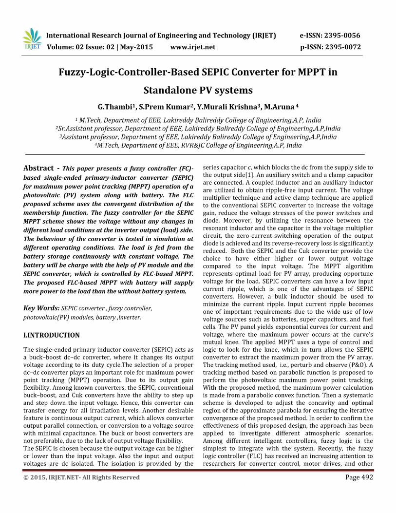
The fuzzy rules of the proposed PV SEPIC dc–dc converter can be represented in a symmetric form, as shown in Table I. Moreover, as in Fig.5, the membership functions of the output variables are nine term fuzzy sets with classical triangular shapes, i.e., negative very big (N4), negative big (N3), negative small (N2), negative very small (N1), zero (Z), positive very small (P1), positive small (P2), positive big (P3), and positive very big (P4). The Mamdani fuzzy inference method is used for the proposed FLC, where the maximum of minimum composition technique is used for the inference and the center-of-gravity method is used for the defuzzification process. Fig. 3 illustrates a focused membership function, where the sets go toward zero. the membership functions in Fig. 3 are guaranteed to produce the stable output signal. The design of the focused membership function values depends on the nature of the signal.
Fig. 4. Three-dimensional surface corresponding to the memberships in Fig. 3 and the rules in Table I.
The control signal value is confined between −1 and 1,owing to the PWM carrier wave. The input signal values are between −100 and 100 because of the error signal, which is resultant from the difference between the output signal and the desired reference signal. In addition, most of error values are centered from −20 to 20. The sharpness of the control signal is very essential for minimizing the error signal to zero in short time; wherefore, the pulse membership function is used to configure the control signal fuzzy sets. The FLC performance changes with unsymmetrical distribution of membership functions, where both convergent and divergent types of asymmetry will be considered with varying degrees of the unsymmetrical membership functions.
IV. PROPOSED MPPT-BASED SEPIC CONVERTER
The fuzzy controller is applied to the SEPIC converter to mimic the new reference signal coming from the MPPT. The new duty cycle δ(k) of the SEPIC converter switch was adjusted either by adding or by subtracting the previous duty cycle δ(k−1) with the duty cycle’s perturbation step size. Equation (1) presents the relation between the present and previous duty cycles, i.e., δ(k) = δ(k−1) Δδ (1)
where Δδ is the change in duty cycle, resulting from the change of reference signal.The MPPT control technique is applied to achieve a new reference voltage for the fuzzy controller, which changes the duty cycle of the PWM signal for the SEPIC converter. The P&O algorithm has a simple structure and requires few parameters (i.e., power and voltage); that is why it is extensively used in many MPPT systems. The P&O method perturbs the duty cycle and compares instantaneous power with past power. Based on this comparison, the PV voltage determines the direction of the next perturbation. P&O shows that, if the power slope increases and the voltage slope increases also, the reference voltage will increase; otherwise, it will decrease. The drawback of most of the fuzzy-based MPPT algorithms is that the tracking point is located away from the maximum power point when the weather conditions change. However, a drawback of P&O technique is that, at steady state, the operating point oscillates around the maximum power point giving rise to the waste of available energy, particularly in cases of constant or slowly varying atmospheric conditions. This can be solved by decreasing the step size of perturbation. The step size of the P&O method affects two parameters: accuracy and speed. Accuracy increases when the step size decreases. However, accuracy leads to slow response when the environmental conditions change rapidly. Step sizes should, thus, be chosen well to achieve high speed and accuracy.The MPPT converter were done using MATLAB/Simulink. The first simulation used the characteristic equations of the PV array, whereas the second simulation used the solar-panel module given in Simulink. The MPPT algorithm was built via (.m) file and linked with Simulink. The SEPIC circuit was built via Sim Power toolbox. Fig. 5 shows the curves for power versus voltage, at 25 ◦C
and 50 ◦C, for radiation variations, from 250 W/m2 to 1000
W/m2. For simulation purposes, the PV panel values and the
number of PV arrays were taken depending on the
experimental setup, The reference voltage signal, tracking the
International Research Journal of Engineering and Technology (IRJET) e-ISSN: 2395-0056
Volume: 02 Issue: 02 | May-2015 www.irjet.net p-ISSN: 2395-0072
© 2015, IRJET.NET- All Rights Reserved Page 495
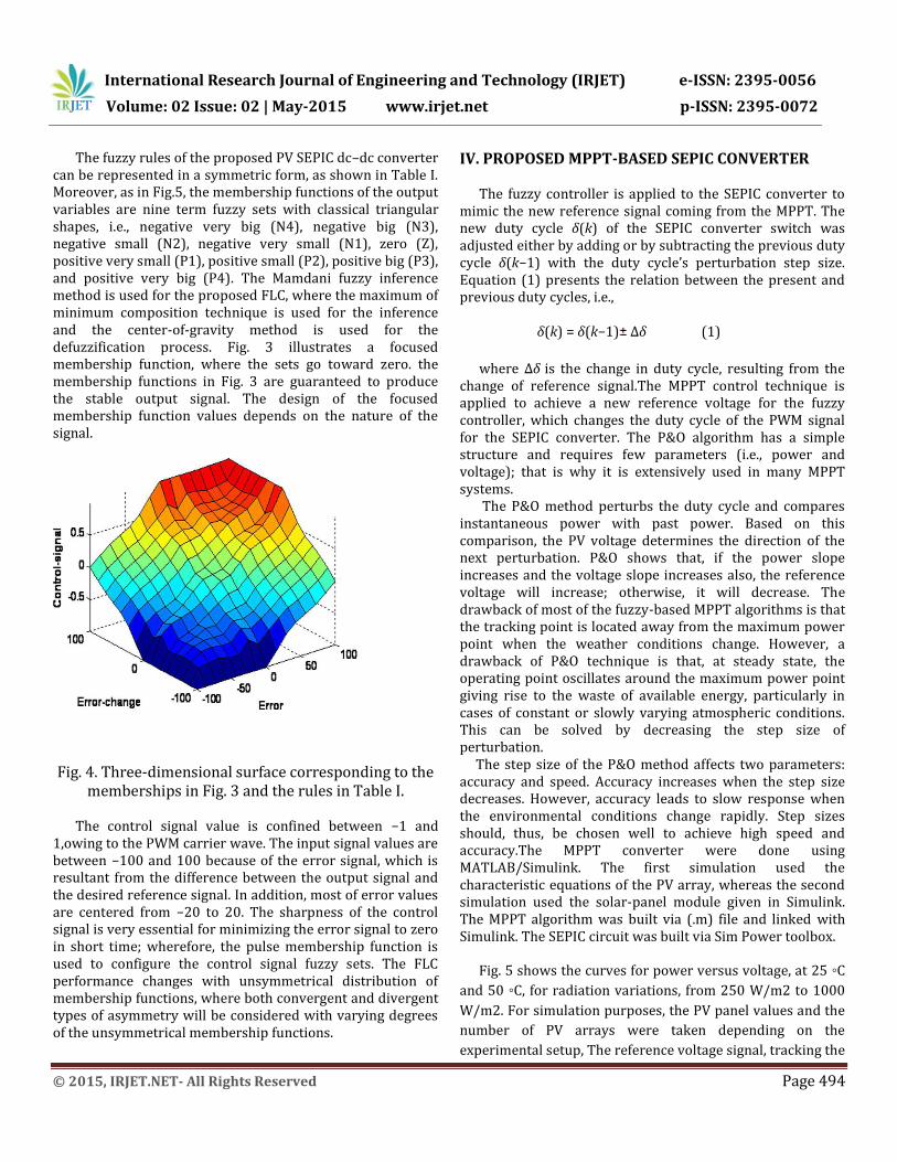
maximum power, is shown in Fig. 6. The relation between
Figs. 5 and 6 can now easily be determined. Hence, it is
clearly noted that the maximum power occurs around 330 V.
Fig. 5. Power–voltage (P–V) relation for the prescribed
PV array.
Fig. 6. (a) Irradiation (W/m2). (b) Reference voltage tracks the maximum power.
V. EXPERIMENT IMPLEMENTATION
The module rated voltage is 17.3 V, as detailed in Table II. An array of 19 series solar modules was setup to generate 330-V dc voltage. Then, the PV array was connected to the SEPIC converter.
TABLE-II
parameters value
maximum power 125W
warranted power 118.8W
rated current 7.23A
rated voltage 17.3V
short circuit current 7.9A
open circuit voltage 21.8V
Two 5-mH inductors are chosen to operate the converter in continuous conduction mode. The values of the input capacitor C1 and the output capacitor C2 are 470 μF and 2200 μF, respectively. The duty cycle changes for closed loop control under variable load conditions. To guarantee that the converter works on continuous conduction mode and to prevent converter damage, the duty cycle has been limited between 0.35 and 0.85.
Fig.7:Sepic output voltage wave form
VI. SIMULATION RESULTS
Simulation was applied on MATLAB/Simulink to verify the practical implementation of the proposed SEPIC fuzzy controller for the single-phase inverter. Fig. 6 presents the reference signal for the SEPIC’s output, where it tracks the maximum power. The output voltage of the proposed FLC based MPPT with battery at constant load condition are shown in Fig. 8. It is noticeable that the signals were not smooth; on the contrary, they carried a component of the maximum power between voltage and current. The voltage range changed from 320 to 340 V. The voltage signal in Fig.8 is similar to the reference signal in Fig. 6.

International Research Journal of Engineering and Technology (IRJET) e-ISSN: 2395-0056
Volume: 02 Issue: 02 | May-2015 www.irjet.net p-ISSN: 2395-0072
© 2015, IRJET.NET- All Rights Reserved Page 496
Fig.8: PV module voltage waveform
TABLE- III
INVERTER SPECIFICATIONS
parameters values
S1-S4 IGBT,600V,GT50J325
LA 3mH,14ASMP
CA,CB 240µF,330V,AC
RL 50Ω,500W
voltage transducer LEMLV25-P
current transducer LEMLA25-NP
PV-output voltage 270-350V,DC
inverter output voltage 240Vrms
switching frequence(S1-S4) 20kHz
switching frequence(Ss) 50kHZ The total Simulink modal of the proposed system was as shown below
Fig.9: Simulink modal of the proposed system.
VII. CONCLUSION
An FLC-based MPPT scheme for the SEPIC converter system for PV power applications has been presented. The performance of the proposed controller has been found better than that of the without battery system. The supply of voltage will be constant to the inverter input side through the battery. The battery will be charge with the help of SEPIC converter. The power usage of the load at the inverter output side was more with the battery system along the FLC based SEPIC with MPPT than the system without a battery. The proposed FLC-based MPPT scheme for the SEPIC converter could be a potential candidate for real-time PV inverter applications under variable load conditions.
REFERENCES
[1] K.M. Tsang andW. L. Chan, “Fast acting regenerative DC electronic load based on a SEPIC converter,” IEEE Trans. Power Electron., vol. 27, no. 1, pp. 269–275, Jan. 2012. [2] S. J. Chiang, H.-J. Shieh, and M.-C. Chen, “Modeling and control of PV charger system with SEPIC converter,” IEEE Trans. Ind. Electron., vol. 56, no. 11, pp. 4344–4353, Nov. 2009. [3] M. G. Umamaheswari, G. Uma, and K. M. Vijayalakshmi, “Design and implementation of reduced-order sliding mode controller for higher-order power factor correction converters,” IET Power Electron., vol. 4, no. 9, pp. 984–992, Nov. 2011. [4] A. A. Fardoun, E. H. Ismail, A. J. Sabzali, and M. A. Al-Saffar, “New efficient bridgeless Cuk rectifiers for PFC applications,” IEEE Trans. Power Electron., vol. 27, no. 7, pp. 3292–3301, Jul. 2012. [5] M. Hongbo, L. Jih-Sheng, F. Quanyuan, Y. Wensong, Z. Cong, and Z. Zheng, “A novel valley-fill SEPIC-derived power supply without electrolytic capacitor for LED lighting application,” IEEE Trans. Power Electron., vol. 27, no. 6, pp. 3057–3071, Jun. 2012. [6] D. Hyun-Lark, “Soft-switching SEPIC converter with ripple-free input current,” IEEE Trans. Power Electron., vol. 27, no. 6, pp. 2879–2887, Jun. 2012. [7] C. Zengshi, “PI and sliding mode control of a Cuk converter,” IEEE Trans. Power Electron., vol. 27, no. 8, pp. 3695–3703, Aug. 2012. [8] A. El Khateb, N. A. Rahim, and J. Selvaraj, “Optimized PID controller for both single phase inverter and MPPT SEPIC DC/DC converter of PV module,” in Proc. IEEE IEMDC, May 15–18, 2011, pp. 1036–1041. [9] A. El Khateb, N. A. Rahim, J. Selvaraj, and M. N. Uddin, “Maximum power point tracking of single-ended primary-inductor converter employing a novel optimisation technique

International Research Journal of Engineering and Technology (IRJET) e-ISSN: 2395-0056
Volume: 02 Issue: 02 | May-2015 www.irjet.net p-ISSN: 2395-0072
© 2015, IRJET.NET- All Rights Reserved Page 497
for proportional-integralderivative controller,” IET Power Electron., vol. 6, no. 6, pp. 1111–1121, Jul. 2013. [10] A. El Khateb, N. A. Rahim, and J. Selvaraj, “Fuzzy logic controller for MPPT SEPIC converter and PV single-phase inverter,” in Proc. IEEE Symp. ISIEA, Sep. 25–28, 2011, pp. 182–187. [11] N. Mutoh, M. Ohno, and T. Inoue, “A method for MPPT control while searching for parameters corresponding to weather conditions for PV generation systems,” IEEE Trans. Ind. Electron., vol. 53, no. 4, pp. 1055–1065, Jun. 2006. [12] F. Pai, R. Chao, S. H. Ko, and T. Lee, “Performance evaluation of parabolic prediction to maximum power point tracking for PV array,” IEEE Trans. Sustain. Energy, vol. 2, no. 1, pp. 60–68, Jan. 2011. [13] N. Femia, G. Petrone, G. Spagnuolo, andM. Vitelli, “Optimization of perturb and observe maximum power point tracking method,” IEEE Trans. Power Electron., vol. 20, no. 4, pp. 963–973, Jul. 2005.
GARA.THAMBI is currently pursuing M.Tech in Power Electronics and Drives in Lakireddy Balireddy College of Engineering, Mylavaram. He received B.Tech degree in Electrical and Electronics Engineering from Tirumala Engineering college in the year 2012. His areas of interest are Renewable Energy Resources and
DC-DC converters.
S.PREM KUMAR received M.Tech.degree from Koneru Lakshmaiah College of Engineering in the year 2008. He is presently working as Sr.Assistant professor in Lakireddy Balireddy college of engineering, Mylavaram. His areas of interest are power systems and power electronics.
Y.MURALI KRISHNA obtained his M.Tech degree from VR Siddhaartha College of Engineering in the year 2012. He received his B.Tech degree from QIS college of engineering, JNTUK in the year 2010. He is currently working as Assistant professor in Lakireddy Balireddy college of engineering, Mylavaram. His areas of interest are
power electronics and Robotics.
M.ARUNA obtained his M.Tech degree from RVR&JC College of Engineering in the year 2008 She did her B.Tech in Electrical and Electronics Enginnering in BVCEC in 2006. He is currently working as Assistant professor in Nalla Malla Reddy college of engineering.


![Implementation of SEPIC/Zeta Three-Port Bidirectional DC ...vanished by introducing the multiport dc-dc converter [5-6]. These multi-port dc-dc converters can interface several number](https://img.dokumen.tips/doc/110x75/5f3cc4b88e446c087f3c5e0b/implementation-of-sepiczeta-three-port-bidirectional-dc-vanished-by-introducing.jpg)


