Embed Size (px)
Citation preview
Fuzzy Logic Control of a Model Airplane
Jon C. Ervin and Sema E. Alptekin Department of Industrial and Manufacturing Engineering
Cal Poly-San Luis Obispo, CA 93407
ABSTRACT
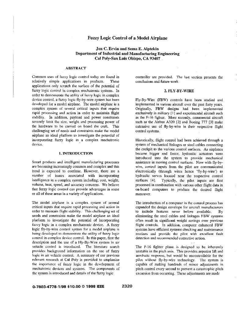
Common uses of fuzzy logic control today are found in relatively simple applications in products. These applications only scratch the surface of the potential of fuzzy logic control in complex mechatronic systems. In order to demonstrate the utility of fuzzy logic in complex device control, a fuzzy logic fly-by-wire system has been developed for a model airplane. The model airplane is a complex system of several critical inputs that require rapid processing and action in order to maintain flight stability. In addition, payload and power constraints severely limit the size, weight and processing power of the hardware to be carried on board the craft. This challenging set of needs and constraints make the model airplane an ideal platform to investigate the potential of incorporating fuzzy logic in a complex mechatronic device.
1. INTRODUCTION
Smart products and intelligent manufacturing processes are becoming increasingly common and complex and this trend is expected to continue. However, there are a number of issues associated with incorporating intelligence in a complex system including; cost, weight, volume, heat, speed, and accuracy concerns. We believe that fuzzy logic control can provide advantages in some or all of these areas in a variety of applications.
The model airplane is a complex system of several critical inputs that require rapid processing and action in order to maintain flight stability. This challenging set of needs and constraints make the model airplane an ideal platform to investigate the potential of incorporating fuzzy logic in a complex mechatronic device. A fuzzy logic fly-by-wire control system for a model airplane is being developed to demonstrate the utility of fuzzy logic control in complex device control. In this paper, first the description and the use of a Fly-By-Wire system in air vehicle control is introduced. The literature search provides background information on the use of fuzzy logic in air vehicle control. A summary of our previous relevant research at Cal Poly is provided to emphasize the importance of fuzzy logic in the development of mechatronic devices and systems. The components of the system is introduced and details of the fuzzy logic
controller are provided. The last section presents the conclusions and future work.
2. FLY-BY-WIRE
Fly-By-Wire (FBW) controls have been studied and implemented in various aircraft over the past forty years. Originally, FBW designs had been implemented exclusively in military [11 and experimental aircraft such as the F-16 fighter. More recently, commercial aircraft such as the Airbus A320 [2] and Boeing 777 [3] make extensive use of fly-by-wire in their respective flight control systems.
Historically, flight control had been achieved through a system of mechanical linkages or steel cables connecting the cockpit to the various control surfaces. As airplanes became bigger and faster, hydraulic actuators were introduced into the system to provide mechanical assistance in moving control surfaces. Now with fly-by- wire, control inputs from the pilot are communicated electronically (through wires hence ‘fly-by-wire’) to hydraulic servos located near the respective control surfaces [4]. Typically, the pilot inputs are first processed in combination with various other flight data in on-board computers to produce the desired flight maneuver.
The introduction of a computer in the control process has expanded the design envelope for aircraft manufacturers to include features never before available. By eliminating the steel cables and linkages FBW systems often result in significant weight savings over previous flight controls. In addition, computer enhanced FBW systems have efficient systems checking and maintenance routines and provide the pilot with excellent fault detection and recommended corrective action.
The F-16 fighter plane is designed to be inherently unstable in the pitch axis. This provides superior lift and aerobatic response, but would be uncontrollable for the pilot without fly-by-wire technology. The system is capable of making hundreds of minor adjustments in pitch control every second to prevent a catastrophic pitch excursion from occurring. These adjustments are made
0-7803-4778-1 /98 $10.00 0 1998 IEEE 2320
by the computer without the pilot even being aware of them throughout the mission. The F-l17a stealth attack aircraft is reported to be unstable about all three rotational axes due to the unusual faceted design required for radar avoidance. The effectiveness of this aircraft would have been severely limited had designers been constrained by aerodynamic stability issues.
In commercial airliners fly-by-wire also means added safety by programming in routines to prevent stalls, over- speeds or uncontrolled flight. There are also features that automatically compensate for an engine failure and add stability in turbulent weather. Backup power supplies and redundant systems are designed into both the A320 and Boeing 777 to reduce the chance of a catastrophic system failure to an extremely low probability.
3. FUZZY LOGIC IN AIR VEHICLE CONTROL
A search of the existing literature provides relatively few but important precedents in the use of fuzzy logic in aircraft control applications. An excellent example of this application is provided by Sugeno in the control of an unmanned helicopter[5]. Sugeno’s helicopter control system uses the knowledge and techniques of an experienced pilot. The on-board fuzzy controller is installed to achieve intelligent control and can be tele- controlled from the ground by issuing verbal commands. The helicopter is stabilized and performs various maneuvers including landings under autonomous fuzzy control.
Another application of fuzzy flight control is a jet trainer that NASA has modified to mimic the response of the shuttle spacecraft[6]. Pilot inputs are sent to a processor employing fuzzy logic to determine the control surface deflections that provide the “feel” of the space shuttle in flight. The result is reported to be a very realistic simulation of the actual shuttle flight handling characteristics.
There are now a variety of tools that can be used in the development of fuzzy control systems. In their development of a fuzzy controlled aircraft, Fournell and Alptekin [7] used FIDE while Montgomery and Bekey [8] report on using MATLABISIMULINK in the development of their flying robot.
Weise and Biezad [9] provide an excellent description of an RC helicopter control project. Included in their study was a test stand for the helicopter which allowed them to get limited flight data in a laboratory environment.
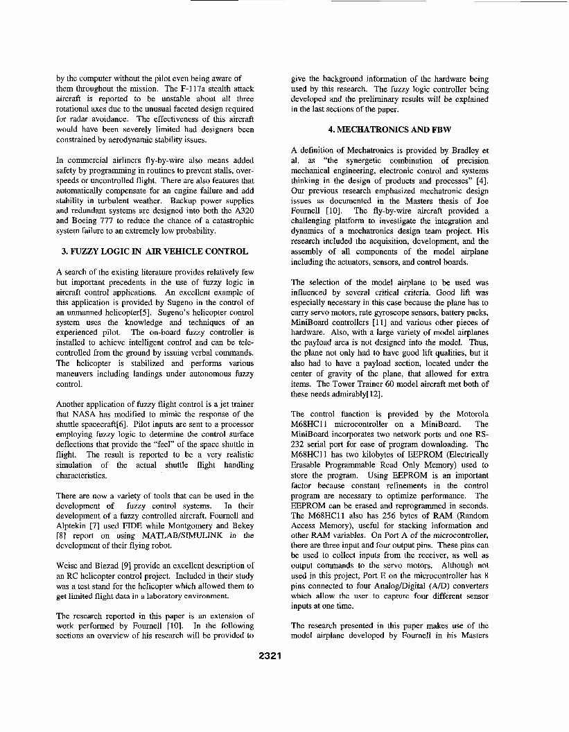
The research reported in this paper is an extension of work performed by Fournell [lo]. In the following sections an overview of his research will be provided to
give the background information of the hardware being used by this research. The fuzzy logic controller being developed and the preliminary results will be explained in the last sections of the paper.
4. MECHATRONICS AND FBW
A definition of Mechatronics is provided by Bradley et al. as “the synergetic combination of precision mechanical engineering, electronic control and systems thinking in the design of products and processes” [4]. Our previous research emphasized mechatronic design issues as documented in the Masters thesis of Joe Fournell [101. The fly-by-wire aircraft provided a challenging platform to investigate the integration and dynamics of a mechatronics design team project. His research included the acquisition, development, and the assembly of all components of the model airplane including the actuators, sensors, and control boards.
The selection of the model airplane to be used was influenced by several critical criteria. Good lift was especially necessary in this case because the plane has to carry servo motors, rate gyroscope sensors, battery packs, MiniBoard controllers [113 and various other pieces of hardware. Also, with a large variety of model airplanes the payload area is not designed into the model. Thus, the plane not only had to have good lift qualities, but it also had to have a payload section, located under the center of gravity of the plane, that allowed for extra items. The Tower Trainer 60 model aircraft met both of these needs admirably[ 121.
The control function is provided by the Motorola M68HCll microcontroller on a MiniBoard. The MiniBoard incorporates two network ports and one RS- 232 serial port for ease of program downloading. The M68HC11 has two kilobytes of EEPROM (Electrically Erasable Programmable Read Only Memory) used to store the program. Using EEPROM is an important factor because constant refinements in the control program are necessary to optimize performance. The EEPROM can be erased and reprogrammed in seconds. The M68HCll also has 256 bytes of RAM (Random Access Memory), useful for stacking information and other RAM variables. On Port A of the microcontroller, there are three input and four output pins. These pins can be used to collect inputs from the receiver, as well as output commands to the servo motors. Although not used in this project, Port E on the microcontroller has 8 pins connected to four Analogmigital (AD)converters which allow the user to capture four different sensor inputs at one time.
The research presented in this paper makes use of the model airplane developed by Fournell in his Masters
2321

0
thesis and enhances the operation of the airplane by incorporating a fuzzy controller as explained in the following sections.
5. RESEARCH GOALS
The primary goal of this research is to determine the potential and issues that arise in using fuzzy logic control in providing aircraft stability augmentation. Two specific research objectives that provide a great deal of latitude in exploring these issues have been identified as follows:
Provide safety augmentation during training for the novice pilot and, Provide stability for new aircraft designs with inherently unstable flight characteristics.
In the first objective we are attempting to provide “training wheels” for the novice pilot. The fuzzy algorithm prevents the pilot from inducing flight conditions which would prove catastrophic to the model airplane. The fuzzy logic controller prevents stalls, slips, spins, and overspeed conditions. Even tighter constraints are placed on the flight envelope when the aircraft is in landing and take-off modes. The Radio Frequency (RF) transmitter is equipped with the capability to toggle the fuzzy logic controller on and off, whenever the trainee feels ready take complete control of the plane.
One of the main issues in this first objective is to determine how much control should be assumed by the on-board electronics and how much is left to the trainee. The algorithm should not be so constraining as to prevent the trainee from taking emergency measures when required, but it should not be so loose as to allow the plane to slip into uncontrolled flight. Future generations will probably allow the trainee to gradually relax the fuzzy constraints as they become more familiar with handling the aircraft.
The second objective would enable the serious hobbiest to design and fly inherently unstable aircraft. The fuzzy controller, operating much like fly-by-wire systems in full scale aircraft, would provide stability in all three rotational axes (yaw, pitch, and roll). The stability augmentation would reduce pilot load and would open up a much larger set of design options for the aircraft enthusiast.
6. FUZZY CONTROL DEVELOPMENT
In this current effort we are developing our system in MATLAB [131 using the Fuzzy Logic Toolbox to define the control rules and membership functions. The various fuzzy logic control algorithms are then imported to SIMULINK within the MATLAB environment to
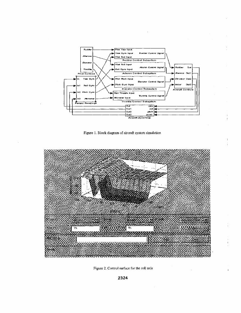
simulate the performance of the complete system. Figure 1 shows a block diagram of the various major components in the simulation environment. Figure 2 shows the fuzzy logic control surface for the roll axis. Control surfaces for the various other inputs take a similar form.
Three single axis rate gyros are used to measure roll, pitch and yaw velocities. The information from these gyros in addition to control commands from the pilot are used as inputs to three separate fuzzy inference systems. In addition, altimeter data is collected and combined with pilot motor control commands providing inputs to a fourth fuzzy system. Each individual fuzzy inference system is programmed into a separate MiniBoard, onboard the aircraft. Output from the Miniboards provide commands to servo motors that move the elevator, aileron, and rudder control surfaces as well as the motor throttle setting.
The original development of the fuzzy rules and membership functions were driven by interviews with an expert pilot. This data was later supplemented by experience gained through the use the CSM Intelligent Technology flight simulator [141. This commercially available simulator is specifically designed for RC aircraft training. The simulator receives input from the pilot through the same transmitter that is used to fly the actual model aircraft. The transmitter is connected to the computer through a cable providing a high degree of realism to the simulation.
Flight characteristics of the aircraft can be modified in the simulation program to provide a close match to the actual RC model. Experience gained from this training was invaluable in refining the fuzzy rules and membership functions. The simulator permitted the exploration of the limits of various flight maneuvers without fear of damage to expensive hardware.
The refinement of the fuzzy rules and membership functions has continued throughout the life of the project. However, after an adequate set of fuzzy inference systems had been developed they were included in the SIMULINK model as shown in figure 1. The SIMULINK model combines all of the fuzzy logic controllers together with sensor and pilot inputs in an attempt to simulate the entire aircraft system. The fidelity of the aircraft dynamics in SIMULINK are not as accurate as that provided by the CSM flight simulator and this discrepancy remains as an area for further refinement.
In the early development of the fuzzy controllers it was assumed that each control surface could be treated independently. In the paper by Sugeno [SI much
2322

emphasis is placed on the importance for allowing for coupling between rotational axes and between rotational and translational axes. An example of coupling in the RC airplane is seen when the pilot attempts a turn. These effects are described in a simple and understandable way by Conway [15]. When rolling into a left turn, the left aileron (figure 3) is raised and the right aileron is lowered. This action provides a net increase in lift to the right side of the aircraft, however the down aileron (right) also increases drag on that side causing a yaw rotation in the direction against the turn. This yaw is countered by applying rudder control in the direction of the turn. Conway describes four other undesirable forces that occur in a simple turn that must be compensated through deflection of various control surfaces.
Compensation for coupling is addressed in this project for only the most extreme instances, such as the adverse yaw effect in a turn. This compensation is provided to help prevent uncontrolled flight conditions that would prove difficult for the novice to correct. Yaw rate gyro sensor data is sent to both the yaw controller and to the roll controller to provide input for coupling compensation. Since the goal is not to provide autonomy in flight, but rather provide assistance in maintaining stability it was not necessary to compensate for secondary coupling effects.
An altimeter similar to that described by Cousin [16]is added to provide data used in take-offs, landings, and to help prevent the novice from allowing the aircraft to wander out of range. The accuracy of this system at +/- 5 meters is not as good as desired but is adequate for this application. A GPS system such as that used by Sugeno [5]would have been more accurate, but would have exceeded budget limitations.
7. CONCLUSIONS AND FUTURE RESEARCH
There are a number of areas for further improvement and extension of this project. Continued refinement of the flight dynamics module in SIMULINK would provide a means of achieving rapid improvement in the control algorithm. Greater sensitivity in the sensors, particularly in altitude would also enhance the system performance. The recent invention of a “Radar on a chip” [17]by Thomas McEwan has the potential of providing altitude data to within tenths of an inch accuracy.
A number of fuzzy control development tools are now available to researchers opening new doors for advanced applications. MATLAB provides a great deal of freedom in selecting membership curves, defuzzification method and inference method to name a few. It is reported that there are advantages to Sugeno style inference in a control problem of the sort being addressed here and this
should be investigated in future work[ 11, [131. There are many opportunities in the hardware to consolidate boards and functions to make a more compact and efficient unit. This project is still very much a work-in-progress, but it has already proven to be a valuable learning experience in the practical application of fuzzy control.
8. REFERENCES
1. “Have Blue”, http://www- scf.usc.edu/-khelrdshaba.html. 2. Burgner, N., “Airbus A320 Family Still Going Strong”, Flug Revue Online, September 1997, http://www.flug-revue.rotor.com/FRHeft/FRH9709a.htm. 3. Ranade S. and J. Darden, “The Evolution of Flight Control Systems”, http://fulton.seas.virginia.edu/-shj2n/case/class/boeing77 7.html. 4. Bradley et al, Mechatronics, Chapman and Hall, 199 1. 5.Sugeno, M., “Development of an Intelligent Unmanned Helicopter”, presentation at the World Automation Congress, May 10-14, 1998, Anchorage, Alaska. 6.Swanson, S. R. ,Fuzzy Control of the Shuttle Training Aircraft, Applications of Fuzzy Logic Towards High Machine Intelligence Quotient Systems, Prentice Hall, NJ, 1997,pg. 387. 7.Fournell J. and S . E. Alptekin, “Fuzzy Logic Fly-by- Wire System”, Proceedings of World Automation Congress (CD), May 10-14, 1998, Anchorage, Alaska. 8.Montgomery J. F. and G.A. Bekey, “Learning fuzzy- neural behaviour-based control through “teaching by showing”. 9. Weise T. M. and D. J. Biezad, “Development of a Digital Flight Data Recorder/ Controller System for a Radio Controlled Helicopter”, Proceedings of ASEE Conference, Seattle, WA, June 1998. 10.Fournell, Joseph A. ,Mechatronic Philosophy: A Fly-by-Wire System, Masters Thesis, Industrial and Manufacturing Engineering Department, Cal Poly San Luis Obispo, June 11, 1997. 11. Martin, Fred, “The MiniBoard 2.0 Technical Reference”, Media Laboratory, MIT, 1994. 12. Tower Hobbies, www.towerhobbies.com. 13. MATLAB, http://www.mathworks.com. 14.CSM 3inl R/C Flight Simulator, Version 9,CSM, England. 15.Conway, C., “The Joy of Soaring”, The Soaring Society of America, 1969. 16.Cousin,H.,“Small Altimeter for Model Rockets”, http://sunsite.unc.edu/pub/archives/rec.models.rockets/E LECTRONICS/readme.txt. 17.“Micropower Impulse Radar”, http://;asers.llnl.gov/lasers/idp/mir/overview.html.
er Contml S gnal
Pilemn Control Signal Rudder Out
Pilemns Out1
Bevator Out2 Eevator Control Signal
tnl Roll Gym
Out y a w 4 I )out 1 roll 4 Out2 pRch 4 Out3 aocrl. 4
Alrcrafl Dynamics
Figure 1. Block diagram of aircraft system simulation
.-,
Figure 2. Control surface for the roll axis
2324
1
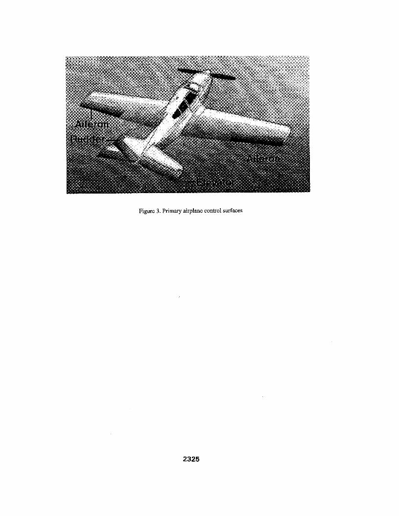
Figure 3. Primary airplane control surfaces
2325