Embed Size (px)
Citation preview

1 INTRODUCTION 1
Fuzzy logic-based embedded system for video de-interlacing
Piedad Brox1, Iluminada Baturone1,2, Santiago Sanchez-Solano1
1Instituto de Microelectronica de Sevilla. Americo Vespucio s/n. 41092 Seville (Spain)Tel.: +34 95446666, Fax: +34 95446600email contact: [email protected]
2Departamento de Electronica y Electromagnetismo, Universidad de Sevilla
Av. Reina Mercedes s/n. 41012 Seville (Spain)
Abstract
Video de-interlacing algorithms perform a crucial task in video processing. Despite these algorithms are developed using softwareimplementations, their implementations in hardware are required to achieve real-time operation. This paper describes the develop-ment of an embedded system for video de-interlacing. The algorithm for video de-interlacing uses three fuzzy logic-based systemsto tackle three relevant features in video sequences: motion, edges, and picture repetition. The proposed strategy implements thealgorithm as a hardware IP core on a FPGA-based embedded system. The paper details the proposed architecture and the designmethodology to develop it. The resulting embedded system is verified on a FPGA development board and it is able to de-interlacein real-time.
Keywords: Embedded system, video de-interlacing, Fuzzy system, IP core
1. Introduction
Video de-interlacing is a key task in digital video processing. Some current digital transmission standards useinterlaced scan format to halve video bandwidth. However, modern display devices require a progressive scan. There-fore, algorithms to interpolate the missing lines during the transmission have to be implemented at the receiver side.This kind of algorithms are called de-interlacing since they perform the reverse operation of interlacing [1].
Digital video processing chain usually includes the four stages shown in the block diagram of Figure 1:
• Reception: video TV is received by a TV decoder, which is in charge of decoding the analog or digital signal.
• Removal of artifacts: analog signal suffers white gaussian noise whereas digital signal is affected by videocompression artifacts, which introduces two kinds of artifacts: ‘block’ and ‘mosquito’ noise.
• Conversion of resolution: signal is firstly converted from interlaced to progressive. After performing de-interlacing, an algorithm for down or up scaling is applied accordingly to the format required by the device.
• Picture improvement: the quality of video signal is enhanced by applying several picture enhancement algo-rithms such as color improvement, sharpness or edge enhancement, and improvements of contrast, details andtextures.
Despite video processing algorithms are developed using software implementations, their implementations inhardware are required to achieve real-time operation. Although primitive consumer equipments had several ASICs

2 ARCHITECTURE OF FUZZY IP CORE FOR VIDEO DE-INTERLACING 2
!"#$%&'()*+%'*+,%*)"&'
-)&).#$'()*+%'*+,%*)"&'
!"#"$%&'()
/%)0+'1+*2,.)%"'
3+*2,.)%"'%4'#1.)4),#.0'*2+'
.%',%561+00)%"'
!"*'+,-)'.),!%&.,#%/)
-+7)".+1$#,)"&'
869-%:"';,#$)"&'
#'(+"!/&'()'.)!"/'-0%&'()
<)*+%'+"=#",+5+".'
$&#%0!")&*$!'+"*"(%)
<)*+%')"62.'0%21,+'
<)*+%'%2.62.'
Figure 1. The four typical stages of digital video processing
to perform each of these four tasks, the current high-end products in the market contain a highly integrated chip toperform the last three tasks and even all the tasks in Figure 1. Video processing chips are included in numerous con-sumer devices, such as Liquid Crystal Display (LCD) TVs, plasma TVs, Audio-Video (AV) receivers, DVD players,High Definition (HD)-DVDs, Blu-ray players/recorders, and projectors. Independently of the video source (during thelast years multiple video sources are proliferating), these chips normally perform intelligent and costly de-interlacingmethods to obtain a high quality output progressive signal.
Concerning video de-interlacing, several choices for hardware implementations are currently available in the mar-ket, such as Application-Specific Integrated Circuits (ASICs) [2]-[9], programmable solutions on Digital Signal Pro-cessing (DSPs) [10]-[14] and/or Field Programmable Gate Arrays (FPGAs) [15]-[18], and Intellectual Property (IP)cores [19]-[23] that can be used as building blocks within ASICs or FPGA designs. Recently, application specificinstruction-set processors (ASIPs) for high speed computation of intra-field de-interlacing have been also proposed[24]. Each of these alternatives offers advantages and disadvantages regarding high performance, flexibility and easyupgrade, and low development cost.
In commercial equipments, ASICs offer the most efficient solution justified by the huge demand of video products.In the other side, FPGAs are a good solution when there is a low volume of consumer products or in the case thatthe aim is to develop a prototype. Furthermore, FPGAs address with the requirement of flexibility and easiness toupgrade. Taking into account these considerations, FPGA implementation is the option chosen herein to implementthe de-interlacing algorithm on an embedded system.
There are many proposals of fuzzy logic-based embedded systems for control applications [25]-[26]. Recentadvances in de-interlacing algorithms propose the inclusion of soft computing techniques to increase the picturequality [27]-[31]. An embedded system that implements the algorithm of [27] in real-time is proposed in this work.To the best of our knowledge this is the first hardware implementation of a fuzzy logic-based video de-interlacingalgorithm. This paper details the implementation strategy that consists of an IP core on a FPGA-based embeddedsystem. The paper is organized as follows. Section 2 summarizes a description of the algorithm and the proposedarchitecture to develop its hardware implementation. Section 3 explains the design methodology to build the IP corefor video de-interlacing. The development of the embedded system and its validation on a development board fromXilinx is detailed in Section 4. Finally, the conclusions of this work are expounded in Section 5.
2. Architecture of fuzzy IP core for video de-interlacing
The algorithm for video de-interlacing is the result of combining three fuzzy logic-based systems, each of themtackling a relevant feature: motion, edges, and possible repetition of areas in fields. The edge-adaptive system is calledspatial interpolator since it performs a non-linear interpolation among pixels in the spatial neighborhood. The systemthat is capable of detecting repeated areas in the fields is called temporal interpolator since it interpolates pixels in thetemporal neighborhood. The third system combines the outputs of the spatial and temporal interpolators according toa motion measurement in the current pixel. A block diagram of the complete system is shown in Figure 2.
The three fuzzy systems are simple since they contain a low number of inputs and a low number of rules in theirrulebases. The spatial interpolator (denoted as FS1 in Figure 2) is an edge-adaptive algorithm that uses five potential

2 ARCHITECTURE OF FUZZY IP CORE FOR VIDEO DE-INTERLACING 3
!"#$"%&
!"#$ !"%$ !"&$'$(($!$)*+$#,& -'.-&
/"++-)*#$"%(&
0%#-+1")*#-'&1$2-)&345&
IS IT
Figure 2. Block diagram of the video de-interlacing algorithm that employs the three fuzzy logic-based system
Table 1. Analysis of storage resources and POs of several state-of-the-art de-interlacers
De-interlacing Algorithm No. of field memories No. of Primitive Operations (POs)MC Field Insertion [32] 1 529MC VT Filtering [32] 1 536
MC TBP [32] 2 535MC TR [32] 2 529MC AR [32] 2 544
GST [32] 1 543Robust GST [32] 1 555
GST-2D [32] 2 559Robust GST-2D [32] 2 571
Algorithm in [27] 3 153
!"##$%&'()*$+'
,-' !-' .-'/-'0-' 1-'2-'3-' 4-'
5' ,' !' .' 6'
7' 2' 3' 4' 8'/%'0%'1%'0'
9#:%;<)&&$='+)%$'
7)$+='>&?@A' 7)$+='>&A' 7)$+='>&B@A'
4%&$#(C+:&$='+)%$'
Figure 3. Pixels used for de-interlacing
edge directions and six fuzzy rules to adapt the interpolation to the presence of edges. The second interpolator (FS2)is a fuzzy area-repetition-dependent temporal interpolator that uses a simple convolution to measure the dissimilaritybetween consecutive fields. It employs two simple fuzzy rules to adapt interpolation to repetition of areas in fields.Despite its simplicity, it reduces considerably annoying artifacts such as feathering. The feature of motion is consid-ered by a fuzzy motion-adaptive interpolator (FS3) that uses a simple convolution to measure the motion at each pixel.This third system evaluates how this motion measurement should influence on the interpolation decisions.
The algorithm for video de-interlacing employs an off-line tuning process to obtain the values of the parameters inthe fuzzy systems as detailed in [27]. The tuning stage has been successfully performed by using a supervised learningalgorithm that minimizes the mean square error between a set of data corresponding to progressive and de-interlacedresults of different standard sequences.
A detailed description of the complete system and its comparison (in terms of PSNR and visual inspection) withother state-of-the-art de-interlacers are presented in [27]. The algorithm is able to improve the results obtained by sev-eral Motion-Compensated (MC) algorithms in areas of the images with small and large motion, with clear and unclearedges, and with film and video material mixed. Concerning embedded system solutions, the hardware implementationof this algorithm is advantageous over the considered MC algorithms, as depicted in Table 1. The number of PrimitiveOperations (OPs) required is quite low. The number of field memories is three since it is necessary to store the valuesof the interpolated pixels in the previous field (as shown in Figure 3).

2 ARCHITECTURE OF FUZZY IP CORE FOR VIDEO DE-INTERLACING 4
Table 2. Rule base of the fuzzy system for motion-adaptive interpolator
Rule Antecedents Consequent1. motion(x, y, t) is S MALL IT (x, y, t)2. motion(x, y, t) is S MALL − MEDIUM γ1 IT (x, y, t)+λ1 IS (x, y, t)3. motion(x, y, t) is MEDIUM γ IT (x, y, t)+λ IS (x, y, t)4. motion(x, y, t) is MEDIUM − LARGE γ2 IT (x, y, t)+λ2 IS (x, y, t)5. motion(x, y, t) is LARGE IS (x, y, t)
2.1. Description of fuzzy logic-based systems for video de-interlacing2.1.1. Fuzzy logic-based system for motion adaptation (FS3)
Motion-adaptive approaches are based on the fact that linear temporal interpolators are perfect in the absenceof motion, whereas linear spatial methods offer a most adequate solution in case that motion is detected [1]. Motiondetection can be implicit, as in median-based techniques, or explicit, using a motion detector. Explicit motion-adaptivealgorithms calculate a new pixel value by interpolating between a spatial and a temporal de-interlacing method:
Ip = (1 − α)IT + αIS (1)
where IS is the output of a spatial interpolator, and IT is the output of a temporal interpolator. The variable α, whichis the output of a motion detector, ranges from 0 to 1 and determines the level of motion. The performance ofexplicit motion-adaptive algorithms relies on the quality of the motion detector, since it is strongly dependent on thecombination of both de-interlacing algorithms.
The fuzzy system (FS3) performs the non-linear interpolation between a spatial and a temporal interpolator accord-ing to the presence of motion. This fuzzy system for motion adaptation has one input, which is a motion measurementbased on the use of bi-dimensional convolution between a matrix of picture differences, M, and a matrix of weights,C. For a current pixel (X), the input of this fuzzy system is as follows:
motion =Σ3
a=1(Σ3b=1Ma,bCa,b)
Σ3a=1Σ3
b=1Ca,b(2)
where M(i, j) are the elements of the following matrix, M, of difference values among three consecutive fields orpictures (see Figure 3):
M =
M(−1,−1) M(0,−1) M(1,−1)M(−1,0) M(0,0) M(1,0)M(−1,1) M(0,1) M(1,1)
=
|B−B0 |
2|C−C0 |
2|D−D0 |
2|Wn−W0 |
2|Xn−X0 |
2|Yn−Y0 |
2|G−G0 |
2|H−H0 |
2|I−I0 |
2
(3)
And Ca,b are the elements of the following weight matrix (their values have been adjusted to ease hardwareimplementation):
C =
0 1 01 2 10 1 0
(4)
The first step of the fuzzy inference process is called fuzzification. It consists of determining the degree to whichthe input belongs to each of the appropriate fuzzy sets via the chosen membership functions. The shape of themembership functions is piece-wise linear since this selection eases the hardware implementation of the algorithm(see Figure 4). Because of linguistic coherence, the degree of overlapping between two consecutive sets is two.
The rule base of the inference system is strongly related to the selection of the number of membership functions(see Table 2). The first rule states that ‘if motion(x, y, t) is SMALL then the interpolated pixel is calculated by applyinga temporal interpolator (IT )’. On the contrary, the rule number five asserts that ‘if motion(x, y, t) is LARGE the inter-polation is performed by applying a spatial interpolator (IS )’. The other three rules consider intermediate situationsthat, when they are activated, perform different linear combinations of the spatial and the temporal interpolators.
The final step to calculate the value of the interpolated pixel is the defuzzification process. Among the defuzzifica-tion methods, the Fuzzy Mean (FM) has been chosen since it is a simplified method that allows hardware simplicity. It

2 ARCHITECTURE OF FUZZY IP CORE FOR VIDEO DE-INTERLACING 5
!"#$#
!"#"$#
%&%
'&()*+,#
-./01
+2/#3&4
(&&#
µ!
5#
"#
!6# !7# !8#
9"# 96# 97#
)%:;;# )%:;;<%&3+.%# %&3+.%# ;:(4&#%&3+.%<;:(4&#
98#
!=#
Figure 4. Normalized piecewise linear functions used for the membership functions. The parameters that define the Z, triangular, and S functionsare break points (ai) and slopes (mi)
Table 3. Rule base of the fuzzy system for edge-adaptive interpolation
Rule Antecedents Consequent1. b is S MALL and c is LARGE and d is LARGE X = B+I
22. b is LARGE and c is LARGE and d is S MALL X = D+G
23. b is VERY S MALL and c is LARGE and d is VERY S MALL X = B+D+G+I
44. a is S MALL and b is LARGE and c is LARGE and d is VERY LARGE and e is VERY LARGE X = A+J
25. a is VERY LARGE and b is VERY LARGE and c is LARGE and d is LARGE and e is S MALL X = E+F
26. Otherwise X = C+H
2
consists of a weighted average of the rule consequents, cr (see Table 2), where the weights are the activation degrees,αr, of the corresponding rules:
FM =
∑r α
r ·cr∑r α
r (5)
2.1.2. Fuzzy logic-based system for edge adaptation (FS1)The fuzzy system (FS1) for spatial interpolation takes inspiration from well-known conventional edge-adaptive
de-interlacing algorithms. This kind of techniques explores a neighborhood of the current pixel to extract informationabout the edge orientation [33]. Among them, Edge-based Line Average (ELA) algorithm interpolates the new pixelvalue by analyzing the luminance differences in the upper and lower lines. ELA looks for the most possible edgedirection and then applies ‘line average’ along the selected direction. The pseudo-code of the ELA algorithm with5+5 taps is as follows (see Figure 3):
i f min(a, b, c, d, e) = b→ X = (B + I)/2elsei f min(a, b, c, d, e) = d → X = (D + G)/2elsei f min(a, b, c, d, e) = a→ X = (A + J)/2 (6)elsei f min(a, b, c, d, e) = e→ X = (E + F)/2else → X = (C + H)/2where : a = |A − J| , b = |B − I| , c = |C − H| , d = |D −G| , e = |E − F|
ELA performs well when the edge direction agrees with the maximum correlation, but otherwise introduces mis-takes and degrades the image quality. The fuzzy inference system proposed in [27] is inspired by the ELA scheme butit uses a rule-based inference system to overcome ELA limitations.
The inputs of this fuzzy system are the edge correlations in the five directions (a, b, c, d, e). As the starting pointto design the rules of the fuzzy system heuristic knowledge expressed linguistically has been applied (see Table 3):
1. An edge is clear in direction b not only if b is small but also if c and d are large.2. An edge is clear in direction d not only if d is small but also if b and c are large.
2 ARCHITECTURE OF FUZZY IP CORE FOR VIDEO DE-INTERLACING 6
Table 4. Rule base for the temporal interpolator
Rule Antecedents Consequent1. dissimilarity(x, y, t) is S MALL X0
2. dissimilarity(x, y, t) is LARGE Xn
3. If b and d are very small and c is large, neither there is an edge nor vertical linear interpolation performs well;the best option is a linear interpolation between the neighbors with small differences: B, D, G, I.
4. If three antecedents are large, that is, no edge is found in the three directions (b, c, and d). An edge is clear indirection a, if a is very small and e is very large.
5. If three antecedents are large, that is, no edge is found in the three directions (b, c, and d). An edge is clear indirection e, if e is very small and a is very large.
6. Otherwise, a vertical linear interpolation would be the most adequate.
This heuristic knowledge is fuzzy since the concepts of ‘small’, ‘large’, and ‘very small’ are not understoodas threshold values but as fuzzy ones. Fuzzy sets SMALL, LARGE, VERY SMALL, and VERY LARGE are againrepresented by fuzzy sets with a piecewise linear functions. The overlapping of the membership functions has beenselected to ensure that no more than two rules are simultaneously activated. This strategy allows the use of theminimum operator as connective ‘and’ since a positive value for the activation degree of the sixth rule is alwaysobtained. FM defuzzification method is used to calculate the output value. The output of the FS1 is the spatialinterpolator, (IS ), which is used in the complete algorithm (see Figure 2).
2.1.3. Fuzzy logic-based system for picture-repetition adaptation (FS2)The simplest temporal interpolator is named ‘field insertion’, and it consists of repeating the pixel with same
spatial coordinates in the previous picture. This technique introduces annoying artifacts such as feathering when theprevious pixel is not a good option. This is especially noticeable in film sequences when the previous field does notcorrespond to the same but to a different frame, which has motivated an active research field on film-mode detectors.
Since de-interlacing should be able to cope with any kind of material: video, film and hybrid (currently verypopular due to the explosion of multimedia market), the idea developed in [27] is to adapt locally temporal interpolatorto the presence of repeated areas in the fields as spatial interpolator was adapted locally to the presence of edges. Inthis sense, area repetition, as edges and motion, is considered, in general, a local (as happens to video and hybridsequences) and fuzzy feature of the image and, hence, two simple fuzzy rules are proposed to implement a pixel-by-pixel fuzzy selection between pixels in the previous (t-1) and posterior (t+1) pictures. The input of these rules is ameasure of dissimilarity between consecutive fields. Taking advantage of previous experience, dissimilarity betweentwo consecutive fields, which is calculated by using a bi-dimensional convolution (as in the case of motion):
dissimilarity =ΣΣM(i, j)C′(i, j)
ΣΣC′(i, j)(7)
where M(i, j) are the elements of the matrix, M, defined in (3) and C′(i, j) are the coefficients of the convolution mask:
C′ =
101
(8)
The influence of dissimilarity in selecting the kind of temporal interpolation is evaluated by considering thefollowing fuzzy rules (see Table 4):
1. If dissimilarity between the fields (t-1) and (t) is SMALL, the most adequate interpolated value is obtained byselecting the pixel value in the previous field at the same spatial position (I(x, y, t − 1)).
2. On the contrary, if dissimilarity is LARGE, the pixel value in the previous field is not a good choice and is betterto bet on the pixel in the next field (I(x, y, t + 1)).
The shape of membership functions to model the fuzzy concepts SMALL and LARGE are also piece-wise linearfunctions. The output of this fuzzy system is given by applying the Fuzzy Mean defuzzification method.

2 ARCHITECTURE OF FUZZY IP CORE FOR VIDEO DE-INTERLACING 7
.
!"##$%%&'()%
*+))'*,-.'%
*+))'*,-.'%
!"##$!$%&'$()*+'&,-*
."/-*0.(%-++$),*+'&,-*
1-2!"##$!$%&'$()*+'&,-*
(),'*'/'),0%
(),'*'/'),0%
Figure 5. Parallel rule processing architecture
2.2. Hardware implementation of the fuzzy inference systems
The proposed architecture to implement the fuzzy inference systems provides a data path for each rule. Thisstrategy is very adequate when the rule bases contain a low number of rules and it provides a high inference speedsince the rules are processed in parallel. The modules that compose the proposed architecture are a memory, aninference unit, a control circuit, and a defuzzification block. The memory stores the values to define the membershipfunctions of the antecedents and the consequents. Since the fuzzy systems have a reduced number of rules, the memorysize required is not large. The connective AND in the antecedents of the rules is represented by minimum operator.The inference can be performed in parallel since there is not a high number of the rule antecedents. The architecturehas multi-input operators dedicated to aggregate the antecedents of the rules. These operators are designed by thecascade connection of two-input operators. The architecture introduces pipeline stages, which separate independentoperations, and allow an overall improvement of the inference speed.
The general structure of the architecture consists of three fundamental stages: the fuzzification stage, whichcalculates the membership degree for each of the inputs; the rule processing stage, in which the activation degreesof the rules are computed, and the defuzzification stage, which provides the system output. A block diagram of theproposed rule processing architecture is illustrated in Figure 5.
2.2.1. Fuzzification stageThere are two well-known strategies to implement the membership functions: memory-based approach and
arithmetic-based approach. Memory-based approaches store the membership degrees of every possible input valueinto a memory. The input value acts as the address of the memory to retrieve the fuzzy labels that are activated andthe corresponding membership functions. The main advantage of this kind of approaches is that there is no restric-tion in the shape of the functions. The main drawback is the memory size, which can be very large to implementhigh-resolution systems, since the size of memory increases exponentially with the bit number of the inputs and thenumber of the resolution bits to code the membership functions. The second approach is particularly appropriatedif the shapes of the membership functions are piecewise linear. The antecedent memory only stores the parametersrequired to carry out the calculation of the functions: the break points and the slopes. The proposed architectureimplements the membership functions by using the arithmetic-based approach in parallel. From a hardware point ofview, this strategy requires more resources but it achieves a high inference speed for real-time purposes.
Three shape of membership functions are implemented: triangular, Z, and S functions (see Figure 4). Froma hardware point of view, this selection has two advantages. The first one is that the parameters stored for eachfunction are a point and a slope. The second one is that only one Membership Function Circuit (MFC) is required tocalculate the two membership degrees per input because the maximum overlapping degree is two and the functionsare normalized, so that calculating one of the degrees, µn, the other is obtained as 1- µn. The flow chart to implement

2 ARCHITECTURE OF FUZZY IP CORE FOR VIDEO DE-INTERLACING 8
µ !
!"#$$%%&'%%
!"#$$(")*+,"%%&-%%µ !")*+,"%%&-%%
&-%%µ !")*+,"($#./)%%
µ !
012'%%3)!%
45%
!"#$$%%&627(089:'%%
!"#$$(")*+,"%%&'(%%µ !µ !
0127%%3)!%
45%
!"#$$%µ !
012;%% 3)!%
45%
012<%%3)!%
45%
!=#.=%
+4>,=%608%
5,=>,=%6%%%%!"#$$?%%%%%!"#$$(")*+,"?%%%%")*+,"?%%%%")*+,"($#./)?%%%%$#./)8%µ ! µ ! µ ! µ !
$#./)%%µ ! &-%%
012@%%
")*+,"%%&-%%µ !")*+,"($#./)%%
$#./)%%µ ! &-%%
µ ! &-%%
!"#$$%%
&62;(089:7%%!"#$$(")*+,"%%
&'(%%
µ !µ !
!"#$$(")*+,"%µ !")*+,"%%
&-%%µ !")*+,"($#./)%%
$#./)%%µ ! &-%%
µ !
&-%%
!"#$$%%
&62<(089:;%%!"#$$(")*+,"%%µ !
µ !
")*+,"%µ !")*+,"%%
&'(%%")*+,"($#./)%%
$#./)%%&-%%
&-%%
µ !µ !µ !
&-%%
!"#$$%%
&-%%!"#$$(")*+,"%%µ !
µ !
")*+,"%%
")*+,"($#./)%%
$#./)%%&'(%%
&-%%
µ !µ !µ !
&-%%
µ !&62@(089:<%%")*+,"($#./)%
3)!%
µ !
Figure 6. Flow chart used to implement the membership functions that are shown in Figure 4
the membership functions in Figure 4 is illustrated in Figure 6. The hardware resources required to implement thesemembership functions are a multiplier, an adder, and registers to store intermediate results.
2.2.2. Rule processing stageA parallel architecture, which computes the activation degree of the rules, is chosen since the rule bases contain
a low number of rules and there is a low number of the rule antecedents. This means that the implementation cost interms of hardware resources is affordable. Furthermore, this solution provides the best performance in terms of timingsince the proposed activation degrees of the rules are evaluated with the smallest number of clock cycles.

3 DESIGN METHODOLOGY FOR FPGA-BASED FUZZY IP CORE 9
!"#
$"#
%#%#
)
)
)
)
)
)
)
)
%#
%#
)
) %#
) )
) ) %#
) ) )
) %#) )
&'(# &)(#
!*#
$*#
!+#
$+#
!,#
$,#
$-#
!-#
!"#
$"#
!*#
$*#
!+#
$+#
!,#
$,#
!-#
$-#
./01/0#./01/0#
Figure 7. (a) Block diagram to implement the Fuzzy Mean defuzzification method in FS3. (b) The divider is suppressed since the sum of theactivation degrees of the rules is equal to one
2.2.3. Defuzzification stageFigure 7(a) shows the block diagram of the parallel architecture to implement the Fuzzy Mean method that is
employed by the fuzzy systems. It requires as many multipliers as the number of rules in the rulebase, adders and onedivider. The divider in equation (5) can be suppressed if the sum of the activation degrees of the rules is equal to one.The shapes of all membership functions are chosen to ensure that no more than two rules are simultaneously activatedand the sum of the activation degrees is always normalized. Hence, the expression in (5) is simplified as follows:
FM → output =∑
i
αi · ci (9)
The block diagram to implement the method in (9) for the case of five rules (as is the case in FS3) is depicted in Figure7(b).
3. Design methodology for FPGA-based fuzzy IP core
The hardware implementation of the three fuzzy systems that compose the algorithm for video de-interlacinghas been done following the architecture detailed in Section 2.2. A methodology has been proven to implement thealgorithm on Xilinx FPGAs. A design flow, which connects the abstract algorithmic level with its physical FPGAimplementation, is depicted in Figure 8. At algorithmic level, Matlab and its Image and Video Processing Toolboxhave been employed to develop the algorithms. Xfuzzy 3 [34] and its integrated tool called xfsl have been used totune the parameters of the fuzzy rule bases. System Generator from Xilinx (XSG) has been employed to developefficient hardware-description-language (HDL) definitions from the schematic diagram described by the designer.XSG consists of a specific blockset for Simulink, called Xilinx Blockset, and the necessary software to translate themathematical model described in Simulink into a hardware model described in HDL language. XSG maps the systemparameters (defined like mask variables in Xilinx Blockset blocks) into entities, architectures, ports, signals, andattributes in the hardware realization with VHDL. The hardware description developed with XSG has been verifiedwith Simulink simulations of test video sequences stored in the Matlab workspace. Finally, CAD environmentsto easily develop FPGA designs from HDL descriptions (in particular, ISE from Xilinx) have been employed todevelop the implementations that perform experimental validation. Furthermore, XSG allows the verification of theimplementation on the FPGA introducing the inputs through the Matlab environment. This verification is also knownas hardware-in-the-loop testing.
A picture of the top level description in the XSG design is shown in Figure 9. Since the design in XSG is integratedinto Simulink, other elements from several blocksets can be used to verify the correct behavior of the design. For

4 DEVELOPMENT OF THE EMBEDDED SYSTEM 10
!"#$ %&%'()$*(+(,-'.,$
/%($
/0123$4$56738$9:8;3<<6=2$'88>?8"$
%@ABA3<6<$ /0C>303=B1D8=$
%/)EF/+G$
!0$ !07>$
53:6H;1D8=$
IJK%J$L8M<60N>1D8=$'3<B$/0123<$4$56738$
<3ON3=;3<$!0$
!?6B$
P9*-$
Figure 8. Computer-aided design methodology
Figure 9. The top level description of the XSG design
instance, the XSG design to implement the fuzzification process for the fuzzy system in charge of implementingmotion-adaptive de-interlacing is shown in Figure 10. The performance of this membership function generator blockcan be verified with a scope element as shown in Figure 10.
4. Development of the embedded system
The previously described fuzzy IP core has been included into an embedded system that implements fuzzy logic-based de-interlacing algorithm meeting real-time requirements.
A Virtex-4 FPGA has been selected as the target device. It is included in the ML402 board of the Xilinx ‘Virtex-4Video Starter Kit’ (VSK). In addition to the ML402 board, VSK contains the Video Input Output Daughter Card(VIODC) board, which is in charge of providing video sources and sinks to the ML402 board. Among the videosources, the camera and VGA signals are used, both with the same resolution (640x480 progressive). The VGA inputsignal is provided by a laptop. Among the available video sinks in the VIODC board, the VGA output is chosen. Inorder to store video output, a video capture board is used on a host PC. The host PC is also in charge of downloadingthe configuration files of the FPGAs (*.bit files) by using a parallel IV download cable. It also enables communicationover a RS-232 serial port.

4 DEVELOPMENT OF THE EMBEDDED SYSTEM 11
Figure 10. XSG design to implement the fuzzification process for the FS1
The system embedded in the Virtex-4 FPGA uses the Xilinx MicroBlaze [35] as general purpose processor incharge of controlling the data flow. The CAD tools of Xilinx Embedded Development Kit (EDK) have been em-ployed to develop the software and hardware configurations of the embedded system. Three IP cores are connected toMicroBlaze by using a dedicated Fast Simplex Link (FSL) bus system based on FIFO communications. The FSL corecalled ‘VIO’ in Figure 11 is used to interface the various video inputs and outputs on the VIODC board. By meansof the VIO, MicroBlaze controls all the video sources available on the VIODC board. The FSL core called ‘DDR’ inFigure 11 allows a parallel access to two external DDR memories, which store video frames. The latest core of thevideo processing channel is the ‘fuzzy de-interlacing’ IP core. This core is obtained by exporting from Simulink toEDK the XSG design described in the previous section as an IP core of MicroBlaze. MicroBlaze and all its cores runat a 100 MHz clock frequency to achieve real-time requirements. Figure 11 shows a block diagram of the completesystem.
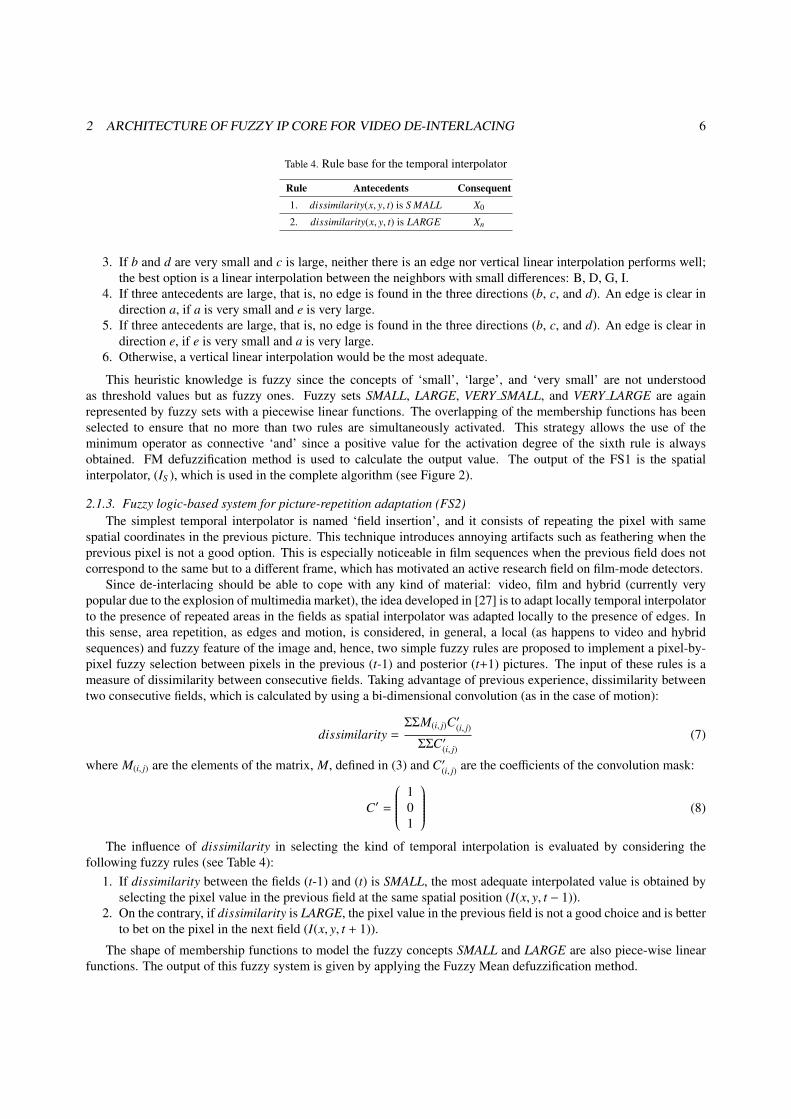
Table 5 shows the implementation results in terms of the FPGA occupational level. The implementation of thede-interlacing system occupies a percentage of approximately 80% of the slices on the Virtex-4 FPGA (this numberconsiders the MicroBlaze and its three FSL cores). The ‘fuzzy de-interlacing’ core requires a very low number ofresources (1211 slices, 7% in percentage). The resources required by the ‘fuzzy de-interlacing’ core are very low be-cause the algorithm has been optimized to use simple operators (such as addition, minimum, and multiplication) andsimple weighting factors that can be reduced to shift operators. In contrast, other de-interlacers proposed in the litera-ture demand heavy arithmetic operations from a hardware point of view. For example, the spatial interpolator MELAin [36] requires a square root, a divider, and an arctan function. Another example is the spatial interpolator FWW in[37], which requires two dividers and a cos function. To illustrate the requirements of these operations, they have beenimplemented on the same Virtex-4 FPGA with the following results of slices utilization: one square root requires 511slices, a divider 809 slices, a cos function 272 slices, and the arctan function 172 slices. Therefore, the implementationof any of these spatial interpolators requires more hardware resources than the complete implementation of the ‘fuzzyde-interlacing’ core.
Figure 12 shows a photo of the complete system while it is working. The embedded system is able to accept aprogressive video signal coming from the camera or the VGA input (the VGA input is used in Figure 12), interlace it,and send the de-interlaced signal to the VGA output in real time.

5 CONCLUSIONS 12
VGA input
VGA output
Camera
VIODC AD9887IC
Video decoder
I2C control
Video data
(Daugther Card)
I2C control ADV7123
MICRON MT9V022
XCV2P7 FGPA
64 bits
ClockVideo data
10-bit DAC
VIO Bus
VIOctrl
Video data input
32 bits
32 bits
Video data outputFSL communication links
DDR
MicroB
laze
ProcessorDDR
SDRAM33 bits
Video data input (real-time channel)
33 bits
32 bits
Video data input (real time channel)
32 bitsDDR
SDRAM
e r
De_interlacing
(real-time channel)32 bits
Video data (from frame buffers)
SDRAM
8 bits
XC4VSX35 FPGA
opb_bus
UART
Signal output (comparison)
33 bits
ML402 Board RS-232 XCVR
PC Terminal
Figure 11. Block diagram of the complete system
Figure 12. Photograph of the complete system
5. Conclusions
This paper presents an embedded system implemented on a FPGA that provides VGA 30 fps (frames per second)real-time video de-interlacing system. The video de-interlacing algorithm employs a hierarchical structure composedof three fuzzy logic-based systems. The algorithm is implemented as hardware IP core following a parallel ruleprocessing architecture that increases the inference speed. Concerning the results for area occupation, an effectiveimplementation is obtained since the proposed algorithm is optimized to use simple operators. A design methodologyis provided to implement it on Xilinx FPGAs.
AcknowledgementsThis work was partially supported by MOBY-DIC project FP7-INFSO-ICT-248858 (www.mobydic-project.eu) fromEuropean Community, TEC2011-24319 project from the Spanish Government, and P08-TIC-03674 project from theAndalusian Regional Government (with support from the PO FEDER). P. Brox is supported under the post-doctoral
REFERENCES 13
Table 5. Implementation results of the embedded system on the Virtex-4 FPGA
De-interlacing system De-interlacing coreNo. of slices 12489 (81%) 1211 (7%)
No. of LUTs 13597 (44%) 1615 (4.9%)
No. of Block RAMs 131(68%) 27(14%)
program called ‘Juan de la Cierva’ from the Spanish Ministry of Science and Innovation.
References
[1] G. de Haan, E. B. Bellers, De-interlacing: an overview. Proc. of the IEEE: 1839-1857, 1998.[2] http : //www.tridentmicro.com[3] http : //www.st.com[4] http : //www.siimage.com[5] http : //www.zoran.com[6] http : //www.micronas.com[7] http : //www.nxp.com[8] http : //www.mstarsemi.com[9] http : //www.marvell.com[10] Z. He, S. Natarajan, De-interlacing and YUV 4:2:2 to 4:2:0 conversion on TMS320DM6446 using the resizer. Application report from Texas
Instruments, pp.1-17, Feb. 2008.[11] C. Peng, Z. He, Y. Cager, An efficient motion-adaption de-interlacing technique on VLIW DSP architecture. IEEE Conference on Advanced
Video and Signal Based Surveillance (AVSS), pp.644-649, Sep. 2005.[12] E. B. Bellers, J. G. W. Janssen, R. J. Schutten, A software approach to high-quality video format conversion. Int. Conference on Consumer
Electronics (ICCE), pp.441-442, Jan. 2005.[13] R. B. Wittebrood, G. de Haan, Second generation video format conversion software for a digital signal processor. IEEE Trans. on Consumer
Electronics, vol.46, no.3, pp.857-865, 2000.[14] R. B. Wittebrood, G. de Haan, Second generation DSP software for picture rate conversion. Int. Conference on Consumer Electronics (ICCE),
pp.230-231, Jun. 2000.[15] D. Van de Ville, R. Van de Wall, W. Philips, I. Lemahieu, Motion adaptive de-interlacing using fuzzy logic. Proc. International Conference
on Information Processing and Management of Uncertainty in Knowledge-Based Systems (IPMU), pp.1989-1996, Jul. 2002.[16] R. Simonetti, A. P. Filisan, S. Carrato, G. Ramponi, G. Sicuranza, A deinterlacer for IQTV receivers and multimedia applications. IEEE
Trans. on Consumer Electronics, vol.39, no.3, pp.234-240, Aug. 1993.[17] P. J. McWillians, S. McLaughlin, D. I. Laurenson, W. B. Collis, M. Weston, P. R. White, Non-linear filtering for broadcast television: a
real-time FPGA implementation. Proc. IEEE Int. Conf. Image Processing (ICIP), vol.3, pp.354-357, Thessaloniki (Greece), Oct. 2001.[18] Y. Yuhong, C. Yingqi, Z. Wenjun, Motion adaptive deinterlacing combining with texture detection and its hardware FPGA implementation.
Proc. IEEE Int. Workshop VLSI Design and Video Technology, pp.316-319, Suzhou (Chica), May 2005.[19] http : //www.algolith.com/en/products/intellectual − property[20] http : //www.zoran.com/IMG/pd f /Frame It 1.pd f[21] http : //www.mstarsemi.com/products/asic ip[22] http : //www.altera.com/literature/ug/ug vip.pd f[23] http : //www.imageproc.com/company.php[24] P. Aubertin, J. M. P. Langlois, Y. Savaria, Real-time computation of local neighborhood functions in Application-Specific Instruction-Set
Processors. IEEE Trans. on Very Large Scale Integration (VLSI) Systems, vol.20, no.11, pp.2031-2043, 2012.[25] A. Cabrera, S. Sanchez-Solano, P. Brox, A. Barriga, R. Senhadji, Hardware/software codesign of configurable fuzzy control system. Applied
Soft Computing 4(3): 271-285, 2004.[26] S. Sanchez-Solano, A. J. Cabrera, I. Baturone, F. J. Moreno-Velo, M. Brox, FPGA Implementation of embedded fuzzy controllers for robotic
applications. IEEE Trans. on Industrial Electronics, 54(4): 1937-1945, 2007.[27] P. Brox, I. Baturone, S. Sanchez-Solano, Soft computing techniques for video de-Interlacing. IEEE Journal of Selected Topics in Signal
processing, 5(2): 285-296, 2010.[28] G. Jeong, S.-J. Park, J. Lee, R. Lee, S. Kim, J. Jeong, Enhancement of interlaced images by fuzzy reasoning approach. Proc. Int. Conference
on Image Processing (ICIP), pp.3117-3120, 2009.[29] G. Jeong, J. You, J. Jeong, Weighted fuzzy reasoning scheme for interlaced to progressive conversion. IEEE Trans. on Circuits and Systems
for Video Technology, vol. 19(6), pp.842-855, 2009.[30] G. Jeong, M. Y. Jung, M. Anisetti, V. Bellandi, E. Damiani, J. Jeong, Specification of the geometric regularity model for fuzzy if-then rule-
based deinterlacing. IEEE/OSA Journal of Display Technology, vol.6(6), pp.235-243, 2010.[31] G. Jeong, S-J. Park, Y. Fang, R. Lee, J. Jeong, Application for deinterlacing method using edge direction classification and fuzzy inference
system. Multimedia Tools and Applications, vol. 59, no.1, pp. 149-168, 2012.[32] G. de Haan, Digital Video Post Processing. Eindhoven, July 2010.

REFERENCES 14
[33] T. Doyle, M. Looymans, Progressive scan conversion using edge information. Signal Processing of HDTV, II. L. Chiariglione, ED., ElsevierScience Publishers, pp.711-721, 1990.
[34] F. J. Moreno-Velo, I. Baturone, A. Barriga, S. Sanchez-Solano, Automatic tuning of complex fuzzy systems with Xfuzzy. Fuzzy Sets andSystems, vol. 158, pp. 2026-2038, 2007.
[35] MicroBlaze Processor Reference Guide (v12.0). Available at: http://www.xilinx.com/tools/microblaze.htm[36] W. Kim, S. Jin, J. Jeong, Novel intra deinterlacing algorithm using content adaptive interpolation. IEEE Trans. on Consumer Electronics,
vol. 53, no.3, pp.1036-1043, 2007.[37] G. Jeong, R. Lee, D. Kim, J. Lee, J. Jeong, Weighted fuzzy filter on interlaced-to-progressive conversion. Proc. IEEE Int. Conf. on Multimedia
& Expo (ICME), pp.173-176, 2008.