Embed Size (px)
Citation preview

Future Role of Safety Tes0ng Technology in Vehicle Design and Development and Highway Safety
1
Professor Cing-‐Dao Kan Wednesday, October 28, 2015
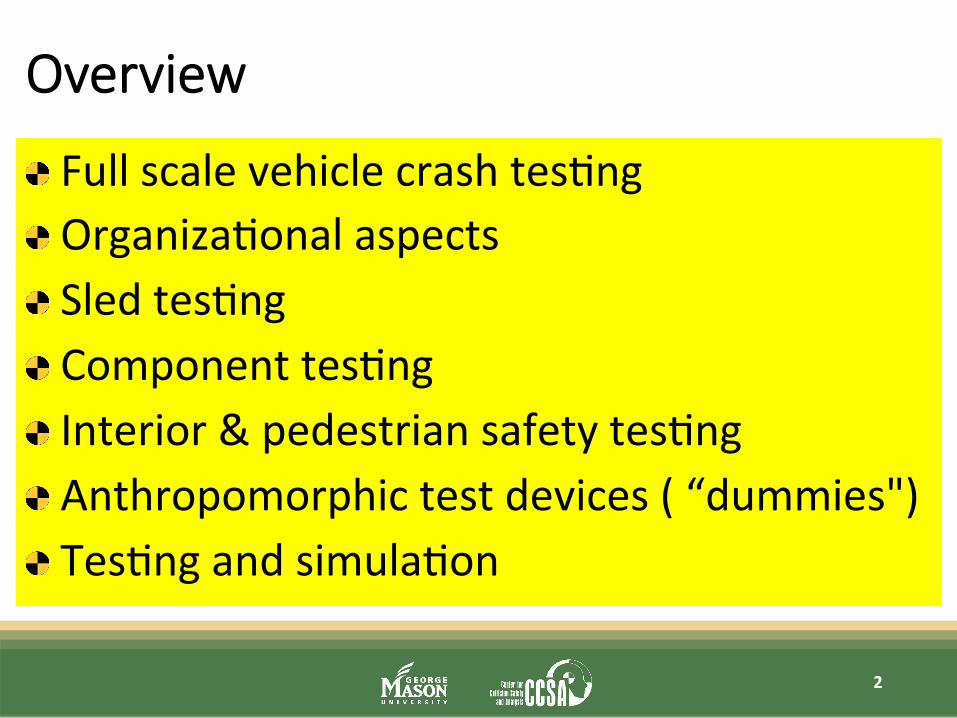
Overview
Full scale vehicle crash tes.ng Organiza.onal aspects Sled tes.ng Component tes.ng Interior & pedestrian safety tes.ng Anthropomorphic test devices ( “dummies") Tes.ng and simula.on
2

Crash test -‐ history
1934: First barrier crash test by GM 1959: First crash test at Mercedes Benz 1979: NHTSA begins crash tes.ng 1997: Euro NCAP’s first results released 2006: China NCAP
3

Crashworthiness then and now
Fatali.es in Germany 1950-‐2010: 1950’s: ~ 6 deaths per 100 million miles traveled in US 2009: ~ 1 death per 100 million miles traveled in US
4
1959 2009

Side Impact – e.g. Oblique Pole Test
“Flying Floor” Pre-‐test prepara.ons “Impact point pin” “Retaining bands” Camera posi.oning Sensor technique 50% male and 5% female front occupants
5

Quasi-‐sta0c roof strength tests
FMVSS 216 (2 sides, 5 inch) IIHS test (1 side, 10inch)
6

Frontal – IIHS Small Overlap Impact
25 % overlap 40mph since 2012
7
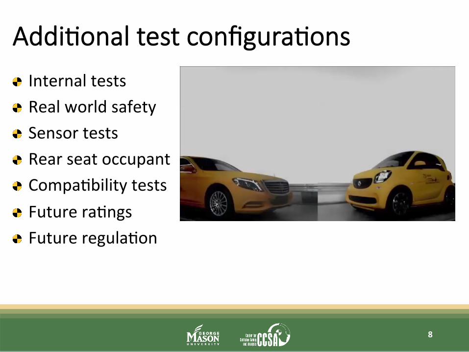
Addi0onal test configura0ons
Internal tests Real world safety Sensor tests Rear seat occupant Compa.bility tests Future ra.ngs Future regula.on
8

Future test – Oblique Impact
9
THOR
Configura.on not final Ac.vi.es in Europe and US New barrier New load paths, kinema.cs New dummy
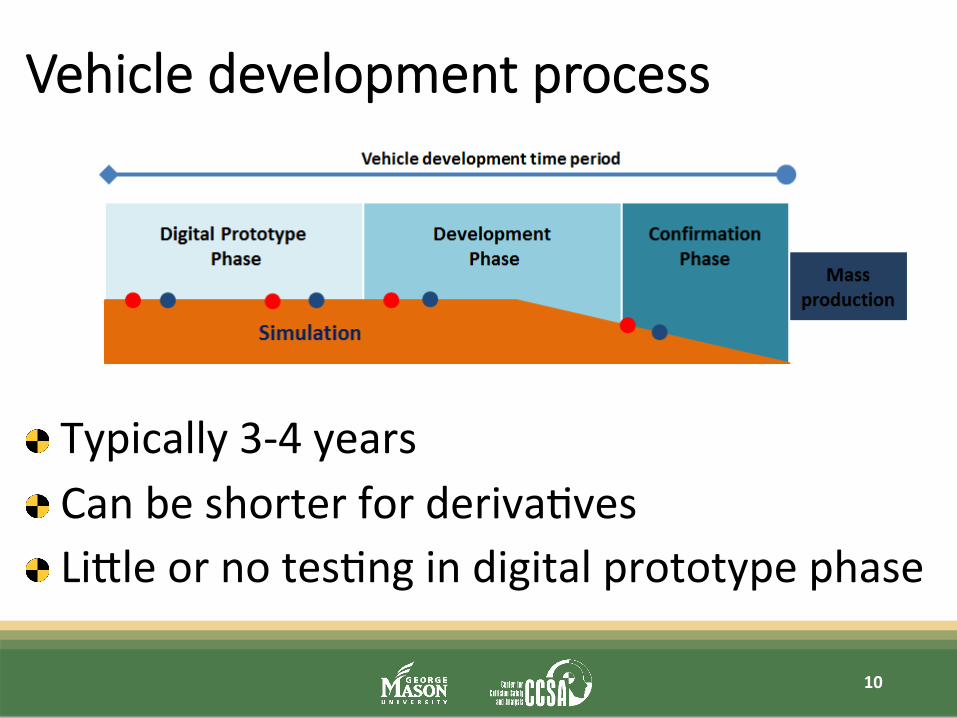
Vehicle development process
Typically 3-‐4 years Can be shorter for deriva.ves Licle or no tes.ng in digital prototype phase
10

Vehicle func0ons
Noise & Vibra.on Analysis Fa.gue & Endurance strength Aerodynamics Analysis Fuel Consump.on Analysis Vehicle Dynamics Ac.ve Safety … Passive Safety
11

OEM -‐ internal interac0ons
12
TesBng (full scale, sled, subsystem, component)
SimulaBon (vehicle structure,
occupant, pedestrian)
Accident Research
(Onsite Inves.ga.ons, Database Analyses)
Design/Project (project management,
styling packaging, cost,
weight..)

Challenges for tes0ng
Increasing number of vehicle plahorms and deriva.ves Increasing number of requirements Stringent development plans Parallel setup and performance of tests Set priori.es which test is necessary (which other tests are being covered, which can be skipped) Highly qualified personnel of different exper.se: … Well organized processes (parts, setup, sensor, post-‐ processing, pictures, filming …)
13
Necessity of sled tes0ng
Very realis.c & efficient for load cases with licle intrusion Complex load cases (e.g. side pole) require more valida.on & upfront sled setup Mul.ple use of sled with prototype/ predecessor interior Simula.on (more realis.c vehicle & intrusion behavior) and sled test (realis.c restraint system hardware characteris.cs) complement each other Many tests with fast adap.on (airbag folding ..) possible Very important (due to reduced & late full scale tes.ng)
14
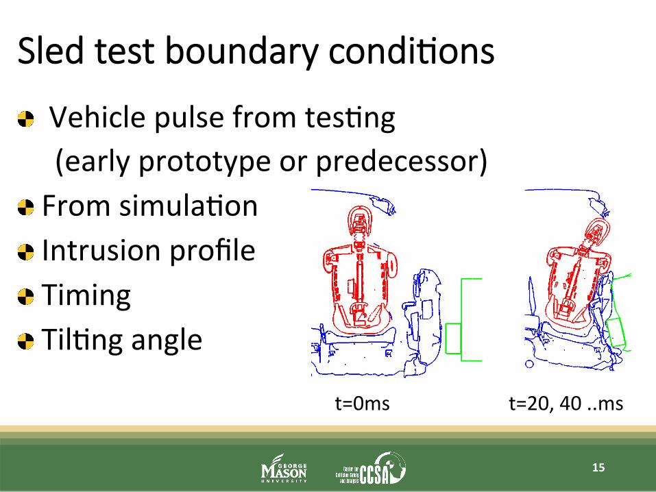
Sled test boundary condi0ons
Vehicle pulse from tes.ng (early prototype or predecessor) From simula.on Intrusion profile Timing Til.ng angle
15
t=0ms t=20, 40 ..ms

Sled test devices
Frontal impact sled Sled with pitching Side barrier sled on sled Side pole test: 1) full vehicle body in white structure on sled 2) sled with predefined hinges, pre-‐deformed
structure (developed using simula.on)
16

Rear impact -‐ Whiplash
BioRID EuroNCAP IIHS
Precise sea.ng procedure Coopera.on with seat manufacturer
17
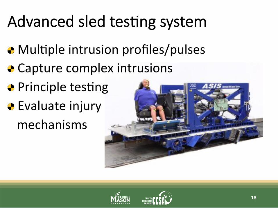
Advanced sled tes0ng system
Mul.ple intrusion profiles/pulses Capture complex intrusions Principle tes.ng Evaluate injury mechanisms
18

Restraint components then & now
1958: Volvo invents 3-‐point seat belt 1971: Airbag patented by Mercedes 1980: Airbag in produc.on (S-‐Class) Today: xx airbags & op.mized restraints
19

Pedestrian safety & Interior impact
20
FMVSS 201u: upper interior head impact protec.on requirement since 1995 (US) Pedestrian protec.on requirements (Euro NCAP)

Pedestrian safety (Euro NCAP)
Head impact Leg impact Adult Child Interdisciplinary teams (tes.ng, simula.on, packaging, styling)
21

Pedestrian safety -‐ Countermeasures
Ac.ve systems Passive systems Affects styling Affects Packaging
22
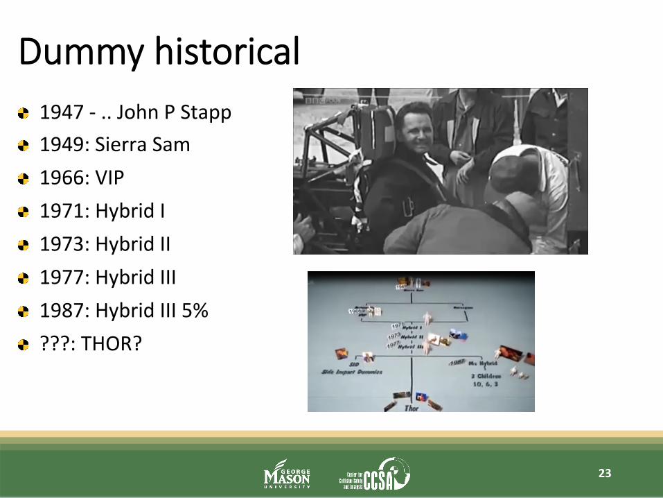
Dummy historical 1947 -‐ .. John P Stapp 1949: Sierra Sam 1966: VIP 1971: Hybrid I 1973: Hybrid II 1977: Hybrid III 1987: Hybrid III 5% ???: THOR?
23

Examples of current & future dummies
24
SID2s: 5th percen.le female BioRID: rear impact, whiplash
WorldSID 50% (EuroNCAP 2015) WorldSID 5% under development
Child dummies Q6 & Q10 used by EuroNCAP (2015)
THOR 50th & 5th percen.le
SID2s
WorldSID Bio-‐ RID
THOR
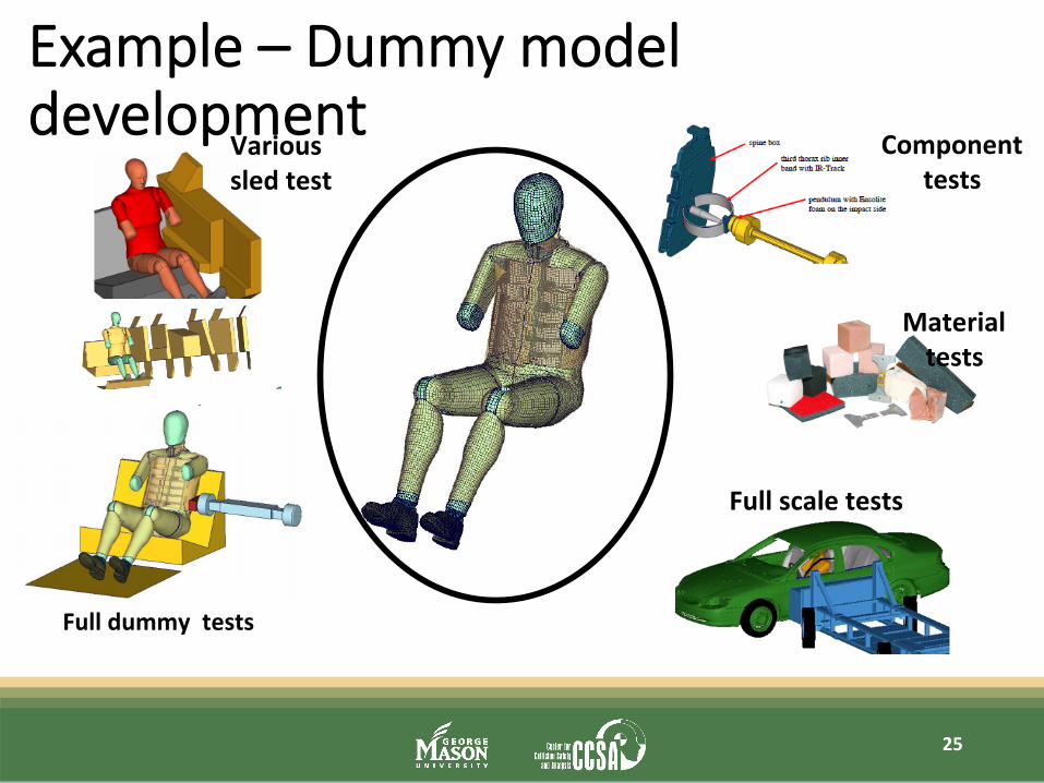
Example – Dummy model development
25
Various sled test
Full dummy tests
Component tests
Material tests
Full scale tests

FAT Dummy development process
26
e.g.
Test results Feedback from full
vehicle test& simula.on
Simula.on model Different codes
Updates

Dummy posi0oning
27
Seat posi.on H-‐Point Manikin Defined distances xyz-‐coordinates

“Climate room”
Ensure right temperature Injury criteria can be temperature dependent Some criteria more sensi.ve than others
28
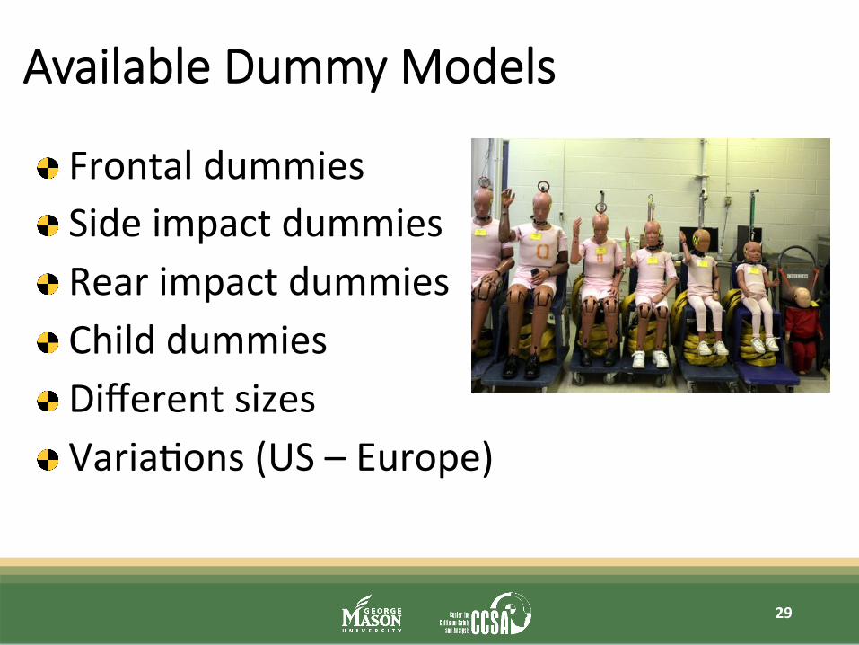
Available Dummy Models
29
Frontal dummies Side impact dummies Rear impact dummies Child dummies Different sizes Varia.ons (US – Europe)
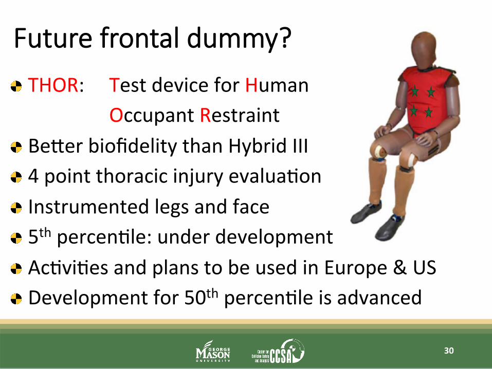
Future frontal dummy?
30
THOR: Test device for Human Occupant Restraint Becer biofidelity than Hybrid III 4 point thoracic injury evalua.on Instrumented legs and face 5th percen.le: under development Ac.vi.es and plans to be used in Europe & US Development for 50th percen.le is advanced

Simula0on then and now
SimulaBon “yesterday”: Coarse meshes, structure only Separate rigid body models No component models from suppliers “Nice to have”, development relied on tes.ng
SimulaBon today: Detailed models (~ 6 million finite
elements for fully integrated model) “Not without” Major contribu.on in development
31

Simula0on & tes0ng organiza0onal
Tes.ng & simula.on work hand in hand Development engineers familiar with both areas Tes.ng engineers can judge simula.on results CAE-‐engineers are integrated in tes.ng tasks Some areas “merged test & simula.on”, e.g. FMVSS201, Pedestrian safety, occupant safety Full scale vehicle & occupant simula.on at OEM Sled test & simula.on at OEM and system supplier Component test & simula.on (airbags, trim ..) at supplier
32

Vehicle development process
Typically 3-‐4 years Can be shorter for deriva.ves Licle or no tes.ng in digital prototype phase Early phase more simula.on dominated, later phase more test dominated
33

Future test & simula0on
Test & SimulaBon work “hand in hand” Complementary use of test & simulaBon results Test of standard load case, SimulaBon of variaBons Passing of certain regulaBons through virtual tesBng (simulaBon) SimulaBon will not replace tesBng but gives addiBonal answers
34

Will we s0ll need all this in the future?
35

36
Thank you
for
your attention!