Embed Size (px)
Citation preview
The HiLumi LHC Design Study is included in the High Luminosity LHC project and is partly funded by the European Commission within the Framework Programme 7 Capacities Specific Programme, Grant Agreement 284404.
Future of the LHC and particle accelerators
Dr Graeme Burt Cockcroft Institute of Accelerator science and technology
Lancaster University

2 G Burt RAL June16
0.75 1034 cm-2s-1
50 ns bunch high pile up 40
1.5 1034 cm-2s-1
25 ns bunch pile up 40
1.7-2.2 1034 cm-2s-1
25 ns bunch pile up 60
Technical limits (experiments too)
50 25 ns
Run I Run II
Run III

3
Goal of High Luminosity LHC (HL-LHC) as fixed in November 2010
G Burt RAL June16
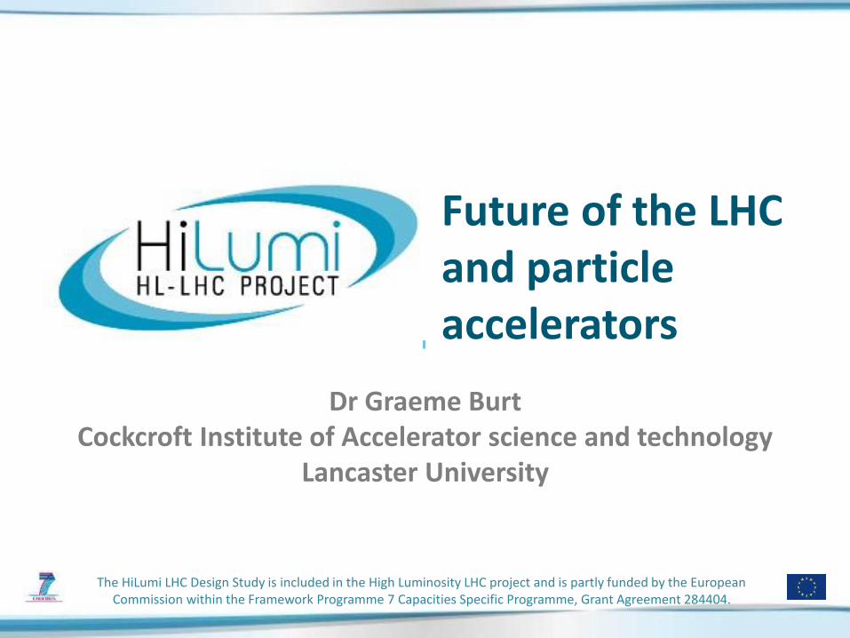
The main objective of HiLumi LHC Design Study is to determine a hardware configuration and a set of beam parameters that will allow the LHC to reach the following targets:
A peak luminosity of 5×1034 cm-2s-1 with levelling, allowing: An integrated luminosity of 250 fb-1 per year, enabling the goal of 3000 fb-1 twelve years after the upgrade. This luminosity is more than ten times the luminosity reach of the first 10 years of the LHC lifetime.
Concept of ultimate performance: under definition: Lpeak 7.5 1034 cm-2s-1 and Int. L 4000 fb-1
4
This goal would be reached in 2036
G Burt RAL June16
M. Lamont, at RLIUP workshop, October 2013
How do we make this jump ?

Luminosity increase • Increasing the crossing angle
decreases the long range effect but decreases geometric overlap
• Rotating the bunches with crab cavities before and after collision can reduce this effect
G Burt RAL June16 5

6
HiLumi: largest HEP accelerator in construction
Interaction Region (ITR) Matching Section (MS) Dispersion Suppressor (DS)
ATLAS CMS
> 1.2 km of LHC !!
Complete change and new lay-out in IP1-IP5 1. TAS 2. Q1-Q2-Q3 3. D1 4. All correctors 5. Heavy shielding (W)
Complete change and new lay-out in IP1-IP5 1. TAN 2. D2 3. CC 4. Q4 5. All correctors 6. Q5 (Q6 @1.9 K?) 7. New MQ in P6 8. New collimators
Modifications 1. In IP2: new DS
collimation in C.Cry. 2. In IP7 new DS
collimation with 11 T
+ Cryogenics, Protection, Interface, Vacuum, Diagnostics, Inj/Extr… extension of infrastr.
G Burt RAL June16

7
But work is required all around the ring…
G Burt RAL June16
Cryo@P4
Cryo@P1-P5
Beam diagnostics BGV
New TAS and VCX

8
The critical zone around IP1 and IP5
G Burt RAL June16
1.2 km of LHC !!

9
The most straight forward action: reducing beam size with a «local» action
G Burt RAL June16
Smaller larger IT aperture
LHC has a better aperture than anticipated: however it is not possible to have < 40 cm
10
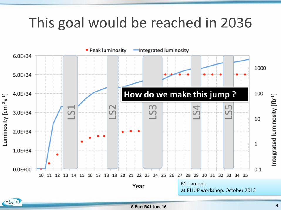
Magnet progress • LHC dipoles features 8.3 T in
56 mm (designed for 9.3
peak field)
• LHC IT Quads features 205
T/m in 70 mm with 8 T peak
field
• HL-LHC
• 11 T dipole (designed for 12.3 T
peak field, 60 mm)
• New IT Quads features 140 T/m
in 150 mm > 12 T operational
field, designed for 13.5 T).
G Burt RAL June16

11
LHC low-β quads: steps in magnet technology from LHC toward HL-LHC
G Burt RAL June16
LHC (USA & JP, 5-6 m) 70 mm, Bpeak 8 T
1992-2005
LARP TQS & LQ (4m) 90 mm, Bpeak 11 T 2004-2010
LARP HQ 120 mm, Bpeak 12 T 2008-2014
LARP & CERN MQXF 150 mm, Bpeak 12.1 T 2013-2020
New structure based on bladders and keys (LBNL, LARP)

12
Crab Cavities for fast beam rotation
G Burt RAL June16

Crab crossing
4 Rod Crab cavities
IR
G Burt RAL June16 13

14
Successful Cold Testings
4 Rod RF Dipole Double Quarter Wave
HiLumi-LHC/LARP Crab Cavity System External Review, May 5-6 2014
G Burt RAL June16

15
Latest cavity designs toward accelerator
G Burt RAL June16
RF Dipole: Waveguide or waveguide-coax couplers
Double ¼-wave: Coaxial couplers with hook-type antenna
4-rod: Coaxial couplers with different antenna types
Coupler concepts
Concentrate on two designs
Present baseline: 3 cavity /cyomodule 4 cavity/cryomod is under study for Crab Kissing TEST in SPS under preparation

16
Low impedence collimators(LS2 & LS3)
G Burt RAL June16
New material: MoGr
17
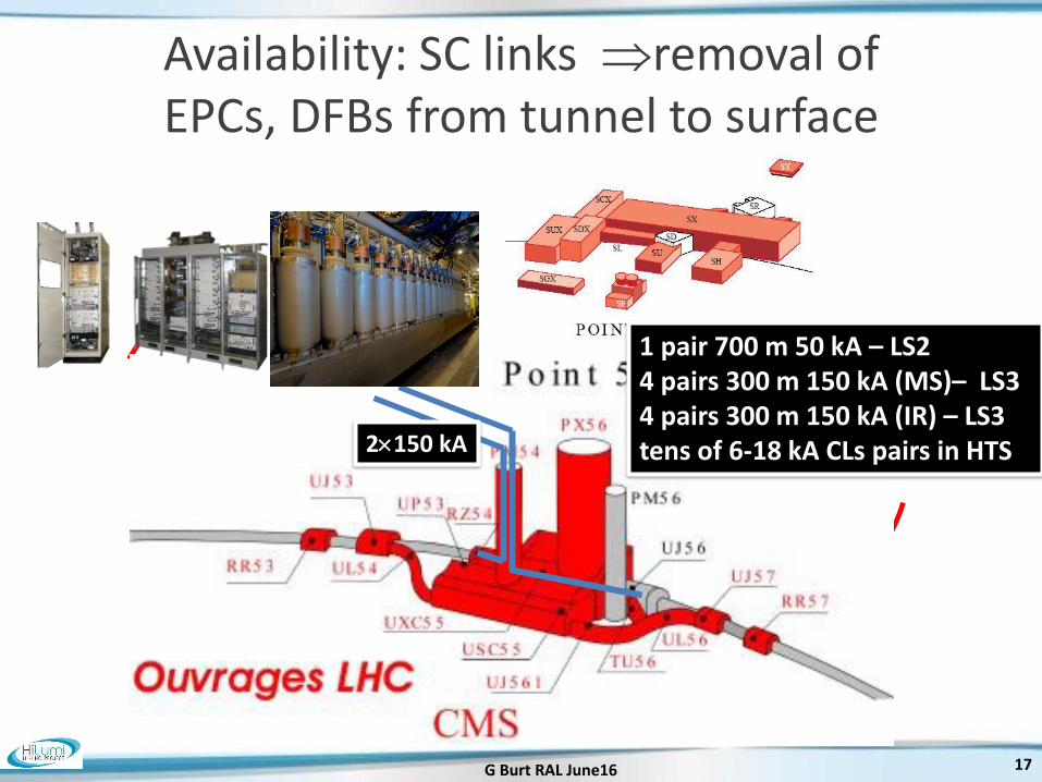
Availability: SC links removal of EPCs, DFBs from tunnel to surface
G Burt RAL June16
2150 kA
1 pair 700 m 50 kA – LS2 4 pairs 300 m 150 kA (MS)– LS3 4 pairs 300 m 150 kA (IR) – LS3 tens of 6-18 kA CLs pairs in HTS

18
G Burt RAL June16
L = 20 m (252) 1 kA @ 25 K, LHC Link P7
Feb 2014: World record for HTS

Challenge 1:
• Crab-cavities will rotate the bunches
• A method to accurately measure the bunch rotation is
required.
• Conventional BPMs have insufficient bandwidth for
single pass, intra-bunch measurements.
• A new technology is needed:
`
Electro-optic crystals as the BPM pickup
The electric field of the passing bunch induces a
polarization change in the crystal that is readout with
<50ps time resolution to derive the transverse position
along the bunch.
. O
3 ( ) ) " (
( " ( =: ( / " > ( " ' ( =! 5 ( >
: ( 5 " ' " 9
+ ( " ( ( 6 $ "
+ ( C / 1 %F
< ) & " ' ( ' " " 6( " 5 " '
< " ' ' ( " " 5 & ,p ' ,
5 "
< ) " " ' ( " " " ( ' ( " ' ( ( ( ' ( "
( ' ' " $ C / " ( " 2 ( ( 6 5 "
"
5
0
# S
S " ( 2 " C ( 1 %F
,5 "
$
"
"
6
! (
V,p
,p
V,p
V,p
,5 "
_ X
6 2 ( / ( 6 " ( ' 6 5
"
Diagnostics
19
Precise measurement of beam parameters is essential. The LHC is equipped with an extensive array
of beam diagnostics that has played a major role in commissioning, rapid intensity ramp-up and safe
and reliable operation of the accelerator. The HL-LHC presents new challenges:
Challenge 2:
• The unprecedented stored beam energy would
damage conventional diagnostics and/or disrupt the
particle beam.
• Non-invasive diagnostics are required to measure the
beam profile and beam halo.
Gas-jet based beam profile monitor
!"
#$
%"$
%#&
$
# " + , - % . " / " ,
/ % - + + ?+. @ 2 / ,
* ( % ( ? ( . #! : 3 ; , ( )
* . 7 % 0 7 / ! H
%4 ) -
' ) / 5 1 * ) ) ( .
7 0 7 ) + 2 8 ?+% ,5?+I ,
* ( % ( ) . . ? +: H,
- - ( ( . / %# 0 / 3 ?/ %! H,
- %/ A A! # - % +A
- +
- +
% )
B$! 5#BB" ) /
? ) ( ,
4 A ?) ( ,
+D* 2 . ( % J
< 2 =
(
=
K "
#%#
L
4 %3 ( + 1
M!
p-beam
!"
#$
%"$
%#&
$
# " + , - % . " / " ,
/ % - + + ?+. @ 2 / ,
* ( % ( ? ( . #! : 3 ; , ( )
* . 7 % 0 7 / ! H
%4 ) -
' ) / 5 1 * ) ) ( .
7 0 7 ) + 2 8 ?+% ,5?+I ,
* ( % ( ) . . ? +: H,
- - ( ( . / %# 0 / 3 ?/ %! H,
- %/ A A! # - % +A
- +
- +
% )
B$! 5#BB" ) /
? ) ( ,
4 A ?) ( ,
+D* 2 . ( % J
< 2 =
(=
K
" #
%#L
4 %3 ( + 1
M!
A supersonic jet of neutral
gas is shaped into a thin
sheet and injected with a
45o tilt across the particle
beam.
Ions produced accelerate
toward a phosphor screen,
to monitor profile
G Burt RAL June16

20
The Crab-kissing (CK) scheme for pile-up density shaping and leveling (S. Fartoukh)
G Burt RAL June16
𝝏𝝁
𝝏𝒛 [mm-1]
z [m]
Baseline: CC in X-plane “only” Crab-kissing & variants: CC also in ||-plane
... Work on-going together with the machine experiments (S. Fartoukh, A. Valishev, A. Ball, B. Di Girolamo, et al.)

21
In-kind contribution and Collaboration for HW design and prototypes
G Burt RAL June16
Q1-Q3 : R&D, Design, Prototypes and in-kind USA D1 : R&D, Design, Prototypes and in-kind JP MCBX : Design and Prototype ES HO Correctors: Design and Prototypes IT Q4 : Design and Prototype FR CC : R&D, Design and in-kind USA CC : R&D and Design UK
ATLAS CMS

HL-LHC-UK
Involvement
Where the UK fits into HL-LHC
22
HiLumi-LHC
Leadership HiLumi-LHC
involvement
G Burt RAL June16

HiLumi-LHC UK
DATA 89170.1Entries 591934
Mean 46.2
RMS 12.92Integral 1
Impact Parameter (mm)0 50 100 150 200 250 300 350
No
rma
lis
ed
Flu
x (
/mm
)
0
0.02
0.04
0.06
0.08
0.1
0.12
DATA 89170.1Entries 591934
Mean 46.2
RMS 12.92Integral 1
MC
Entries 3294
Mean 48.42RMS 13.37Integral 1
MC
Entries 3294
Mean 48.42RMS 13.37Integral 1
Source
DATA 89170.1
MC
Impact parameter 0.53A 3.5TeV LSS beam gas left of IR8
Superconductivity
and Cryogenics Machine-detector interface
Beam dynamics
Crab Cavities
Collimation
Manchester
Liverpool
ASTeC
Manchester
Manchester
Liverpool
ASTeC
Manchester
Lancaster
ASTeC
Manchester
RHUL
HL-LHC-UK
Southampton
Diagnostics
Liverpool
RHUL
G Burt RAL June16 23

24
What’s next? • Energy upgrade of LHC with new Nb3Sn dipoles?
• A 80/100 km tunnel as a higgs factory and then a 100 TeV pp
collider (FCC)? Could CERN afford such a large machine that
cannot be staged?
• Chinese Higgs factory or FCC? Could they get the international
community to buy in?
• A staged linear collider going to 1 TeV (ILC) or 3 TeV (CLIC)? ILC
could be built now, CLIC still has some technical challenges.
• An electron-ion collider (LHeC, ELIC, e-RHIC)? We can do it if
the HEP community wants it enough.
G Burt RAL June16

New “Conventional” breakthrough's
• High field dipole magnets
allowing projects like FCC.
• N-doped, Nb3Sn and
Multilayer SRF provides
higher Q, higher
temperature and higher
fields.
• High gradient X-band still
going strong and replacing
old S-band technology
25 G Burt RAL June16

Novel or Advanced Accelerators • Laser-Plasma-based electron and hadron accelerators:
• Driven by lasers (for both e- and hadron) e-: Multi-GeV beams have been
achieved beam energy sufficient for applications applications around
the corner???
• Hadrons: ion beams have been produced and transported at low energies
• Activities at many centers in Europe (as well as US and Asia)
• This dominates the novel acceleration arena
• Excellent future sources of compact accelerators but can they be used for
HEP?
G Burt RAL June16 26
Laser Plasma Accelerators Efficiency and rep-rate
• Efficiency is at least one or two order of magnitude less than conventional sources (around 1% if that). For a 1 TeV collider at CERN the required power would dwarf the rest of Geneva (roughly 10 times the entire energy budget of Geneva) and would potentially require several new dedicated power stations.
• Rep-rate is limited by material heating to sub-1Hz, this would limit luminosity.
• Laser efficiency and rep-rate could be increased by
• OPCPA but would need new pump sources that are also more efficient and can handle higher average powers, currently can demonstrate either high power, high efficiency or high rep-rate but only one at a time.
• Combining fibre lasers but locking that many lasers is far from realisable at present. Progress has been made on locking tens of lasers (ICAN) together but millions would be required.
• . 27 G Burt RAL June16

28
Staging of laser plasma • At present a few GeV beams can be obtained, but higher energies need
either
• Higher power lasers (material heating limits are difficult to overcome)
• Combining multiple stages.
• The laser stability coupled with the sensitivity to the laser parameters means every shot is different and most have poor beam quality. Typical variation is 1-5% energy, 5-50% charge, 1-3mrad beam pointing.
• The phase space for external injection is very small in both longitudinal (fs synchronisation) and transverse planes. We are far from a point where we can get close to staging and there are few theories on how this could be achieved.
• Also holes in the mirrors for beam injection get burnt by the laser meaning they need replaced or repositioned frequently.
• Even if we could proposals either require very high laser mean powers (GW) or very high rep rates (15 kHz)
G Burt RAL June16

29
Accelerator size • The laser travels slower than c in the plasma while electrons travel
close to c hence you loose synchronisation after a few mm. The gradient is very high (10’s GV/m) but acceleration is limited to synchronisation length
• Several items of equipment would be required around each plasma stage, the laser itself, vacuum pumps, mirrors, beam transport and diagnostics. In a conventional linear accelerator these items can be 20-50% of the accelerators length. For example a plasma FEL would be only half the size of conventional ones.
• The lasers and power supplies are very large so the gradient is often overstated. In conventional sources we have two numbers active length and total length. LPWA have a small active length but the total length is still significant. Still smaller than linacs but not by as much as implied.
G Burt RAL June16

Are there other options or are we stuck with conventional accelerators until we can stage plasma?
• YES!!!!
• Lasers could be used with dielectrics to overcome the stability
issues and reach gradients up to 1 GV/m. Using THz
lasers/vacuum tubes significantly increases beam quality over
shorter wavelength sources in dielectrics. Efficiency still is an
issue at present. Good for medical linacs and light source
replacements. Good potential for higher efficiency THz
vacuum tubes (harmonic gyrotrons, BWO’s) or wakefield
driven could allow path to TeV colliders.
• You could drive the plasma with a proton or electron beam as
opposed to a laser. The drive beam could be a highly efficient
high current beam. This would be far more efficient and stable
than a laser plasma accelerator. Likely the most viable option
for a novel multi-TeV collider other than traditional
accelerators. But luminosity is low
30 G Burt RAL June16
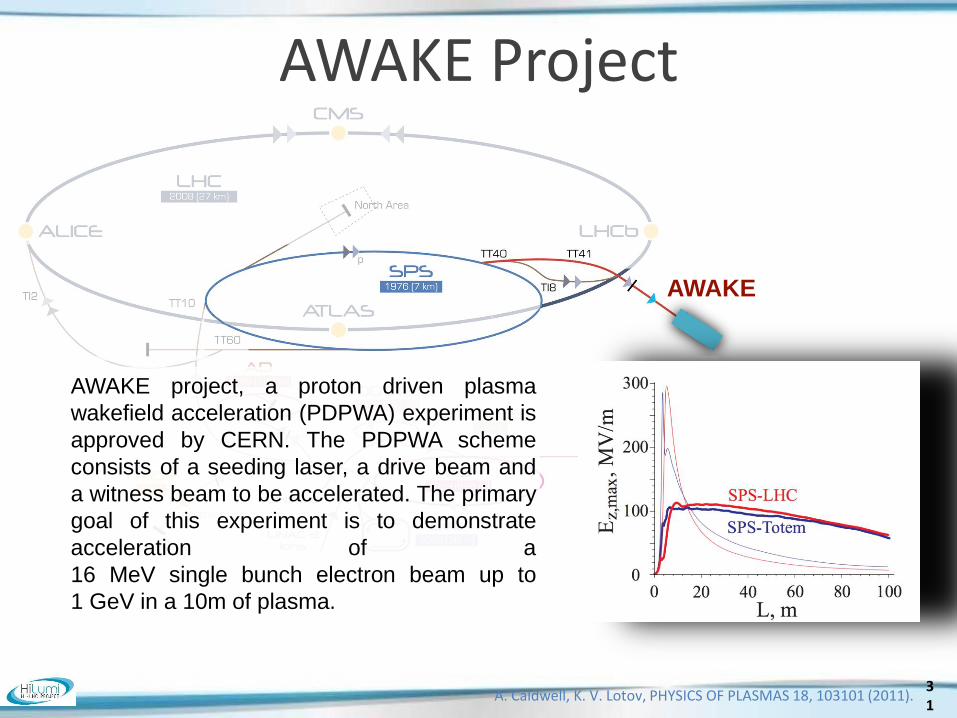
AWAKE Project
AWAKE
A. Caldwell, K. V. Lotov, PHYSICS OF PLASMAS 18, 103101 (2011).
AWAKE project, a proton driven plasma
wakefield acceleration (PDPWA) experiment is
approved by CERN. The PDPWA scheme
consists of a seeding laser, a drive beam and
a witness beam to be accelerated. The primary
goal of this experiment is to demonstrate
acceleration of a
16 MeV single bunch electron beam up to
1 GeV in a 10m of plasma.
31

Laser Power Supplies
Lasers
Access Gallery
Plasma Cell
Electron Spectrometer
Electron Beam Line
Proton Beamline
Experimental Diagnostics
Klystron System
Electron Gun
Production of a Witness Beam
32
AWAKE Project

An electron-positron collider
33
A. Caldwell, K. V. Lotov,
PHYSICS OF PLASMAS 18, 103101 (2011).
Electron beam energy with
plasma density step-up.
1 TeV e+/e- beam in 2 km of plasma
‣ Via plasma step up and self modulation
instability.
LHC radius, 4.3 km
‣ Transfer and matching of protons&plasma.
‣ Dedicated e- source
‣ 2 km plasma section (0.5 GeV m-1).
‣ 2 km beam delivery and final focusing section.
‣ “Used” protons to be extracted, dumped or may
be recycled.
G. Xia, O. Mete et al.,
NIMA Volume 740, 11 March 2014, 173–179 Luminosity is limited by LHC filling time. However rather than use LHC we could develop a faster cycling machine with looser beam quality specs.

Issues of Proton Driven Plasma Wakefield Acceleration
Bunch lengthening due to
energy spread and focusing
issues of protons. Production of accelerating field by using a
hollow plasma for positron acceleration.
ion
e-
Electron beam scattering by plasma
electrons and ions - luminosity
degradation through emittance
growth
34
‣Phase slippage
‣ Interaction of “driver” beam with plasma
‣ Interaction of “witness” beam with plasma
‣ Positron acceleration (in case of e-p collider)
34
Group velocity of wakefields is the same as the velocity of the driver, protons. Electrons may overrun the wakefields - no acceleration.

PWFA at Cockcroft Institute
PWFA at VELA user station in 2015 First experiment on plasma lens started in August 2015
PWFA at CLARA front end in 2016
Demonstration of high acceleration gradient ~ GV/m
Two bunch acceleration for high quality beam production
PWFA at CLARA in 2020
High beam quality preservation, ultrahigh brightness e-
production, e.g. plasma photocathode E=4.8 MeV Q=250 pC σz = 3.3 mm σr = 0.45 mm focusing gradient of 10 T/m
E=50-150 MeV Q=250 pC σz = 20-100 μm σr = 50 μm acc. gradient ~GV/m
acc. grad. 1.8 GV/m
Guoxing Xia et al.
E=250 MeV, Q=250 pC Eacc~ 3 GV/m
G Burt RAL June16 35

Dielectric Accelerators Types
• Photonic structures
• Dielectric Wakefield Accelerators (like CLIC but with dielectric)
• Dielectric RF Linacs (replace RF structure with dielectric)
• Dielectric Wall Accelerators (high voltage switches)
• THz/Laser driven dielectric accelerators (high frequency linacs)
Why?
• Dielectrics can have very high gradients if the right material is
used (5.5 GV/m shown in experiments but not with acceleration
yet)
• They can operate at high frequencies, THz or higher (smaller)
• Can potentially have lower long-range wakefields (for photonic
structures)
• Simpler to manufacture (in some cases)
36 G Burt RAL June16
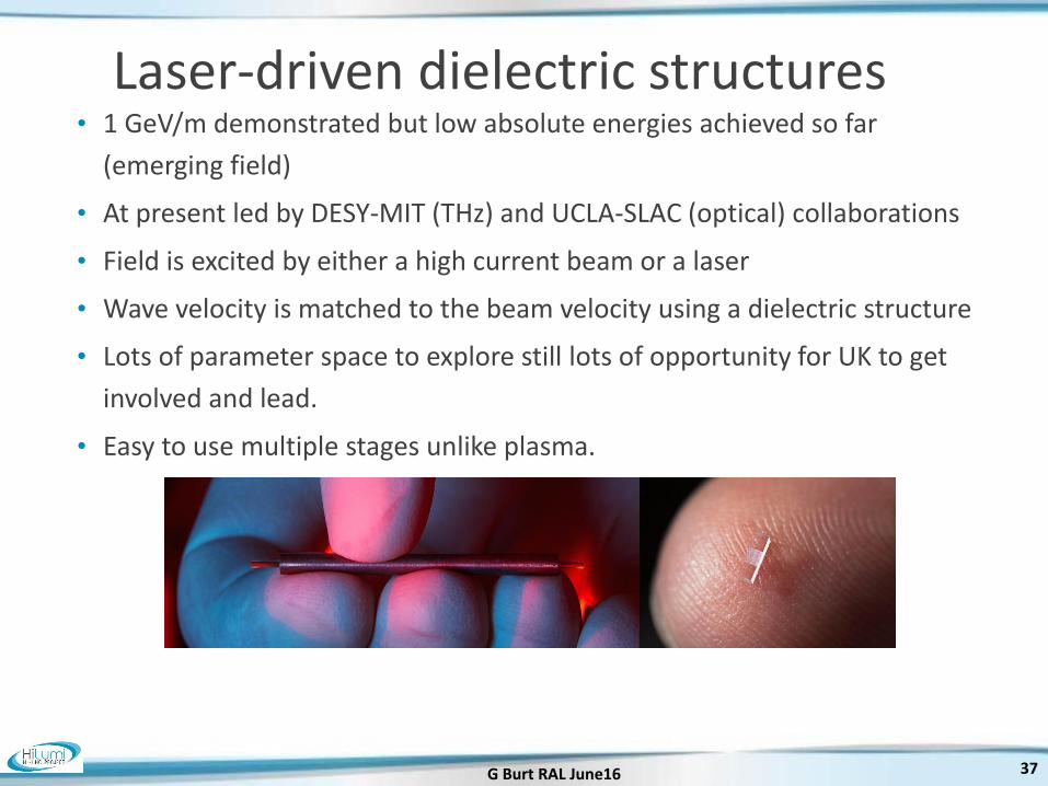
Laser-driven dielectric structures • 1 GeV/m demonstrated but low absolute energies achieved so far
(emerging field)
• At present led by DESY-MIT (THz) and UCLA-SLAC (optical) collaborations
• Field is excited by either a high current beam or a laser
• Wave velocity is matched to the beam velocity using a dielectric structure
• Lots of parameter space to explore still lots of opportunity for UK to get
involved and lead.
• Easy to use multiple stages unlike plasma.
37 G Burt RAL June16
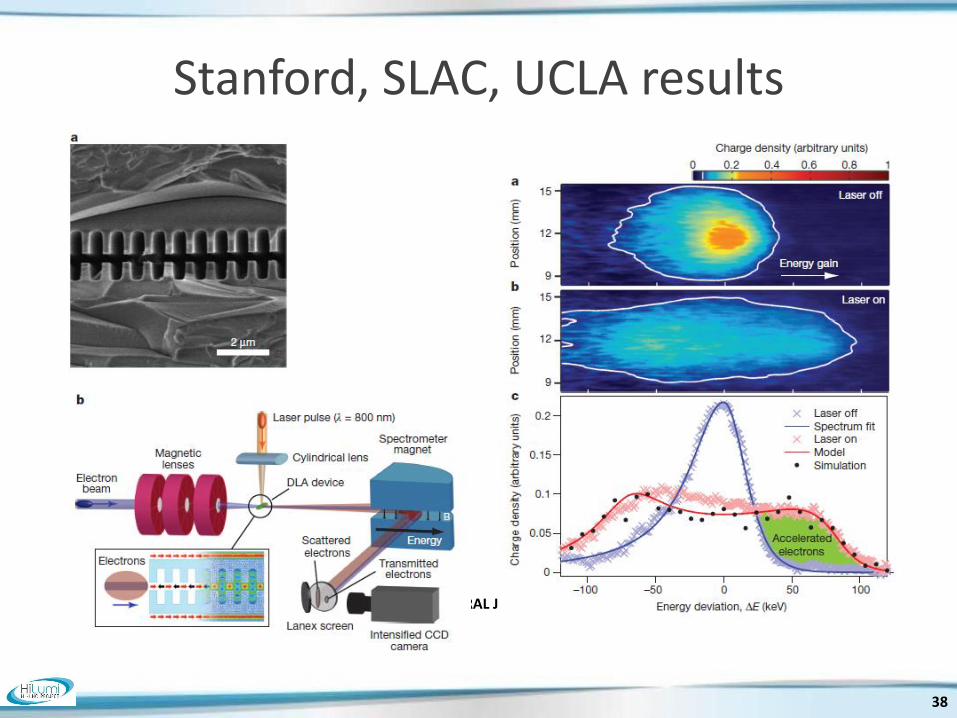
Stanford, SLAC, UCLA results
G Burt RAL June16
38

39
Terahertz driven dielectric linacs Terahertz vs. optically driven
All particles are accelerated with THz
Terahertz Microwave Infrared Shrink the size and cost of future high energy colliders
Nat. Commun. 6, 8486 (2015)

40
Conclusions
• The next big HEP accelerator project will be the
LHC luminosity upgrade, now in the
prototyping phase.
• HL-LHC-UK will develop UK accelerator
contribution
• LHC results will determine what happens next
• In the far future we are looking to beam-driven
plasma and dielectrics to develop higher
energy colliders.
G Burt RAL June16