Embed Size (px)
Citation preview
■ 6 IEEE CIRCUITS & DEVICES MAGAZINE ■ JANUARY/FEBRUARY 20068755-3996/06/$20.00 ©2006 IEEE
CHIPThe
This article presents an overviewof the most important effectsthat handover considerationshave on the design of multi-
standard mobile radio transceivers. Itspecifically points out the multitude ofdesign issues and challenges thatshould be taken into account in theRF/analog front-end part. Many of theseissues have not been widely consideredyet by the relevant communities thoughthey are instrumental in achieving analways-best-connected mobile terminal.
BACKGROUND4G is a technology unifier that willallow several communication standardsto converge in order to provide an opti-mum solution for a given situation. Forexample, as shown in Figure 1, when amobile user connected to a cellular net-work enters a wireless local-area net-work (WLAN) hotspot, the mobileterminal may switch from using a high-mobility, low data rate standard, suchas the global system for mobile commu-nications (GSM) (licensed band), to alow mobility, high data rate standard,
such as IEEE 802.16-2004, IEEE802.16e (aka WiMAX), or IEEE 802.11b(aka Wi Fi) in order to optimize a cer-tain set of benefits such as cost. Whenthe user leaves the WLAN hotspot, themobile terminal switches back to GSMor WiMAX. This scenario requires mul-tistandard support in the mobile termi-nal itself, a challenge that is partly facedin this article.
This scenario will be taken to itslogical conclusion, at least in the Unit-ed States, when more new spectra willbe made available simultaneously inthe next few years than are now usedby the satellite TV, PCS, and WLANindustries combined [1]. The reasonfor this is that the state of availableradio technologies and governmentpolicies, the main issues that dictatedthe scarcity in available spectra in thepast, are simultaneously goingthrough a radical change.
This research focuses on handoverconsiderations from the mobile termi-nal front-end designer’s perspective.The issues that will be raised andresearched explore the space of possible
implementations of wireless front-endsby keeping in mind that, optimally, themobile terminal, in an attempt toremain “always-best-connected,” willhave to continuously explore its sur-roundings and select the best networkconnection available by taking intoaccount several factors, including therequirements of the applications that itis running. This should be done withoutsignificant interruption, optimally lead-ing to intersystem seamless handover, atleast from the user point of view. Somecompanies are already attempting toprovide services and products dealingwith these issues, such as OptiMobile AB[2] and Motorola’s CN620 [3].
THE CONVERGENCE CHALLENGEThe multistandard trend will havemany implications on the design of atransceiver front-end. The first is thatmost front-end chips on the markettoday either support only one standardor a few of the same family, thus hav-ing similar requirements. As a result, adevice that supports a multitude of dif-ferent standards will contain severalfront-end chips. This has severe cost,area, and power implications makingthis solution an impractical one, espe-cially for consumer-oriented, hand-held devices that should be smallenough and have low power consump-tion for long-term usage.
In addition to the need to minimizethe number of chips, multistandard sup-port presents a new challenge: intersystem
Future 4G Front-Ends Enabling Smooth Vertical Handovers
Jad G. Atallah and Mohammed Ismail
Welcome to The Chip! We wish our readers all the very best in 2006!We kick off the year with an article on handover in fourth generation (4G)
wireless. While a definition for 4G is not very clear so far, there is a vision thatgenerations beyond 3G will be able to achieve seamless, always-best-connectedwireless services.This means that users of mobile devices will be able to connectto the “best” wireless infrastructure available (cellular, Wi Fi, WiMAX) anytime,anywhere where “best” could be perceived as best quality of service, best price,best security, etc. Among other things,the article addresses possible chip setsolutions towards bringing this vision to reality. I hope you find it of interest.
We look forward to recieving your comments and contributions. Happy 2006!Mohammed Ismail
Mohahammed Ismail, Editor

7 ■IEEE CIRCUITS & DEVICES MAGAZINE ■ JANUARY/FEBRUARY 2006
handover while the device is operating.Handover procedures between differentsystems are being studied at higher levels,but these procedures themselves may dic-tate a lower bound on the number of front-end multi-standard chips. This is because,while the device is communicating usingone standard, it should periodically moni-tor its environment in order to exploitalternative wireless connections by choos-ing the most suitable one.
Taking the above considerations intoaccount, will we need to implement twomultistandard front-ends: one to moni-tor the environment and the other tokeep the present applications running,or will we be able to support therequired features by using a single wire-less front-end that can do both jobs in arepetitively successive manner such asthe Quorum Connection (QC) 2530solution promoted by Quorum Systems,Inc. [4]? An obvious answer to the ques-tions above does not exist, as we willsee. What are the factors to look at inorder to obtain an optimal implementa-tion for a set of standards?
WIRELESS TRANSCEIVER DESIGN CHALLENGE
Over the past few decades, the successof high integration as a means for real-izing fast and low-power digital systemswas reflected in an ever-decreasing costof implementation. However, RF/analogparts do not scale as digital systems do;RF front-ends, in particular, make useof many passives that make up most ofthe die area. For example, a voltage-controlled oscillator, an integral part ofany up/down converter, contains one ormore inductors, a relatively large struc-ture. The inductance is a function of theinductor’s size. This means that if wewant to have a certain frequency outputfrom the oscillator, we will have to keep(approximately) the same size of theinductor irrespective of the technologyused. Therefore, the price per area ofthe inductor increases when it is imple-mented in a cutting-edge technologycompared to when it is implemented inan older one. As a result, a higher per-centage of the chip area will be con-sumed by the RF/analog part. This leadsto a lower space usage efficiency, lead-
ing to lower performance/cost ratio.This will be reflected in the desire toreduce (or even eliminate) the RF/ana-log components as envisioned by thepromoters of software-defined radios.
Multistandard devices originally areimplemented by having physically dif-ferent and independent radios. Anexample is a laptop with several connec-tions: one through a PC card accessingthe GSM network, a second to WLANthrough a chipset, and a third to Blue-tooth through yet another chipset. Thisapproach worked well. However, thetrend is to have this kind of multi-network support embedded in devicesno larger than a mobile phone, whichpushes towards integrating thesetransceivers in a more efficient way.
A transceiver can, in general, bedivided into two parts: the front-endRF/analog part and the back-end digitalpart. This division exists because thesetwo parts were historically developed bydifferent groups using different tech-nologies. The digital back end hasproven to be more amenable to highintegration than the analog front end.As a result, we are starting to see truemultistandard, single-chip, digital base-band solutions on the market, such asSandbridge’s SB3000 [5]. New architec-tures are being explored, such asMotorola’s Reconfigurable ComputeFabric (RCF) [6] and Quicksilver’s Adap-tive Computing Machine [7] that can bereconfigured on the fly at run time in aslittle as a single clock cycle. These chipsbenefit from all the enhancements thatcome from the digital processing arena,such as parallel-processing. As a result,a single chip can be highly pro-grammable so as to be compliant even
with standards that the chip designeroriginally did not know of.
The analog part cannot be as gener-ic as the digital part. More precisely, inaddition to having to choose the stan-dards that should be supported, thedesigner must also decide whether thechip should communicate via morethan one standard at the same time, asin Figure 2. Single-chip, multistan-dard, analog solutions that are beingused today do not have an equivalent tothe parallel-processing features that thedigital chips have. This is due to the factthat analog components currently mustbe physically switched in order to sup-port another standard. As a result, evenif true multistandard analog front-endswill be attained, the problem would beto decide on how many we should haveoperating in parallel. Additionally, con-sidering the issues raised above, it isimperative to be as thrifty as possible inthe number of analog front-ends, espe-cially considering that, in general, thesize of each one of them will be largerthan that of a single-standard front end.
WIRELESS STANDARDSThree types of personal communica-tions services system integration can beidentified based on their radio technolo-gies and network technologies [8].These types are, namely, similar radiotechnologies, same network technology(SRSN), different radio technologies,same network technology (DRSN), dif-ferent radio technologies, and differentnetwork technologies (DRDN).
Our interest is in the compatibilitybetween different wireless standardswith respect to their radio interface.Therefore, in order to preserve generality,
1. Interstandard mobility.
WLAN 3
WLAN 2WLAN 1
Cell1 Cell2

■ 8 IEEE CIRCUITS & DEVICES MAGAZINE ■ JANUARY/FEBRUARY 2006
we are basically interested in the DRSNand the DRDN cases. More specifically,we are interested in data-link layer com-patibility, since it is taken for grantedthat the lower physical levels will be dif-ferent anyway, hence requiring physicalswitching in the analog front-end.
If the mobile terminal has two ana-log front-ends (one primary and onesecondary), then the next question to beraised is whether the secondary front-end, responsible for exploring the envi-ronment (and possibly establishingconnections with other networks),should support the full protocol stack.Thus, is it possible to divide the proto-col stack into pieces where only thenecessary pieces are implemented forevery front-end?
If we take the extreme case of havinga single analog front-end switchingback and forth between different stan-dards in order to explore its surroundingand/or establish a handover, then theonly way it can “trick” the standardswith which it is communicating is byjumping out of the communicationchannel in order to talk with the otherstandard and come back without eitherof them realizing the discontinuity.Thus, the device takes advantage of any“silent” time that the logical connectioncan provide. An example of this is theQuorum Connection (QC) 2530 that
interleaves WiFi packets into unusedGSM slots while still ensuring that GSMcalls receive priority [4]. Both optionsare shown in Figure 3.
Logical-link layers are originallyconceived within the realm of one stan-dard so as to maximize the efficiency ofa single network. However, little con-sideration is given to how much thelogical-link implementation could helpsolve the issue raised here, i.e., whenthe device is involved in some inter-standard handover. Specifically we askwhether it is possible to introduce someimprovements in order to harmonizethis link-level layer, making it easier toswitch from one standard to another.This issue has been raised a lot in thenetwork layer and above, especially inthe context of mobile IP as in the asso-
ciated request for comments (RFCs) [9].However, issues at the datalink andphysical layers have not been studieddeeply yet.
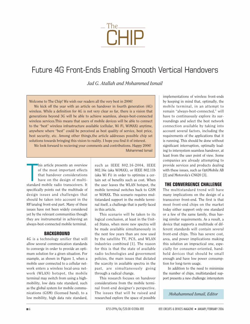
A summary of the chosen standardsis shown in Table 1, where DECT standsfor digital enhanced cordless telecom-munication [10]–[12].
First, a few remarks regarding han-dover procedures will be made in orderto have a global view of the options thatare present.
HANDOVER INITIATIONHandover can be initiated either due tocoverage loss in the present communi-cation mode or if a preferred mode isdetected as illustrated in Figure 4. How-ever, standards differ in the way theymeasure the link in order to determine
2. Current situation of device partitioning.
Front-End 1
Front-End 2
Front-End 3
Switched Front-Ends
UnifiedBack-End
Multistandard Wireless Device
3. Possible front-end implementations: (a) one unified front-end operating in time-division mode and (b) two unified front-ends: one for handling thecurrent connection and one for searching for an alternative connection.
Multistandard Wireless Device
UnifiedFront-End 1
Handles theCurrently ActiveCommunication
Channel
UnifiedFront-End 2
Searches for anAlternativeConnection
UnifiedBack-End
Multistandard Wireless Device
UnifiedBack-End
FastReconfigurationfor Time-Division
Operation
(b)(a)
UnifiedFront-End
9 ■IEEE CIRCUITS & DEVICES MAGAZINE ■ JANUARY/FEBRUARY 2006
the quality of the channel. In general,there are two metrics that are used todetermine the quality of a channel inorder to do a handover [8]:
✦ Received signal strength indica-tion (RSSI)—As a measure ofreceived signal strength, theRSSI metric often has a largeuseful dynamic range, typicallybetween 80 and 100 dB.
✦ Quality indicator (QI)—Estimateof the “eye opening” of the radiosignal, which is related to the sig-nal to interference and noise (S/I)ratio, including the effects of dis-persion. QI has a narrow range(from about 5 to perhaps 25 dB).
Ideally, the handover decision shouldbe based on distance-dependent fadingand, to some extent, on shadow fading,but not on multipath fading which canbe addressed by other methods.
However, the problem that arises inmultistandard situations is that han-dover may be vertical, i.e., from onestandard to another. This will affect theinitiation of the handover. Handovermay be mobile controlled (such as inDECT), network controlled, or mobileassisted (such as in GSM). In our sce-nario, it is preferable that the handoverbe mobile controlled, since of all thecomponents in the network, the mobileterminal has the best perspective of whatalternative links it can handover to. Onthe other hand, the network should alsobe informed so traffic is routed to thenew connection. The handover itself cantake between 100 and 500 ms for DECTand up to 1 s for GSM.
A good starting point for the inter-standard handover study is the inter-working between GSM and DECT. Astandard has already been publishedregarding this (see the next section).
Afterwards, we will try to extrapolatefrom this standard in order to include alow tier (narrow-range) standard otherthan DECT, such as IEEE 802.11b.
INTERWORKING BETWEEN GSM AND DECT
The European TelecommunicationsStandards Institute (ETSI) specifiesadditional requirements to the existingGSM and DECT standards needed forDECT/GSM mobile terminals that canbe manually switched between DECTand GSM mode and/or can performbackground scanning and switch auto-matically and/or can have both modesactivated at the same time [13]. Thisstandard provides a good starting pointto study mobile terminal interoperabilitybetween GSM and other standards.
Terminal ConfigurationsA mobile terminal for DECT and GSM isconsidered to be a terminal with oneGSM part and one DECT part that is con-trolled by a common interworking unitthat also controls a common interface.
Some parts in the terminal, such asmicrophone and loudspeaker, could bereused by both the GSM and DECTparts or could be duplicated. Integra-tion of the RF parts is also foreseen.Several possible hardware configura-
tions can be envisioned for such amobile terminal. For example, the ter-minal could contain two entirely sepa-rate transceivers, simply sharing thekeyboard, display, microphone, ear-piece, etc. Completely independentoperation may then be possible, butthere will be difficult technical issues ofreceiver blocking to overcome. It is alsopossible for parts of the transceivers tobe common, reducing the cost of theterminal, but also limiting the possibili-ties of simultaneous operation. Theexact functionality of the interworkingfunction will depend on the terminalconfiguration.
The different possible radio configu-rations may also have an impact on thenetworks. They will also affect the per-formance specifications, which the ter-minals can meet. However, it isundesirable to have different regulatoryrequirements dependent on the imple-mentation of a mobile terminal, so thisshould be avoided.
Five general terminal configurationsdenoted as Types 1–5 have been identi-fied [14]. The essential differencesbetween the terminal types are summa-rized in Table 2. The Type 3 terminal issubdivided into a and b categoriesdepending on whether simultaneousreception is supported.
4. Conditions under which handover is initiated.
A Preferred Mode IsDetected
Coverage Is Lost
Handover Initiation
Multiple Frequency Channel Frequency Modulation DataStandard Access (MHz) Spacing (Hz) Accuracy rate (bps) Max. Power (W)
GSM TDMA/FDMA/FDD 890–915, 935–960 200 K ±90 Hz GMSK 270.83 k 0.8, 2, 5, 8DECT TDMA/TDD 1880–1900 1.728 M ±50 KHz GFSK 1.152 M 250 mIEEE802.11b DSSS (CDMA) 2412–2472 5 M ±25 ppm DBPSK 1 M 1
DQPSK 2 MCCK 5.5 M
11 M
Table 1. Summary of the chosen standards.

■ 10 IEEE CIRCUITS & DEVICES MAGAZINE ■ JANUARY/FEBRUARY 2006
Of these mobile terminal types, Type1 is the only truly basic type, Types 2 and3 are identified as interesting for earlyimplementations, and Types 4 and 5 areconsidered as advanced and are for laterimplementations.
General Switching BehaviorThe mobile terminal is in GSM orDECT mode, or it could have bothmodes activated at the same time. Ineach mode, in general, the mobile ter-minal shall operate as the correspond-ing single mode terminal and shallfully comply with the relevant stan-dards for that single mode terminal.When one mode is being activated ordeactivated, the mobile terminal shalloperate like a single-mode terminalthat is switching on or off. Locationregistration within each mode shall beperformed according to the relevantstandards for single-mode terminalsand the behavior when switchingmodes is the same as when a single-mode terminal is switched off and thesecond terminal is switched-on.
The possible ways of a mobile termi-nal dealing with several air interfacesare stated below and in Figure 5:
✦ Manually switched operation (themobile terminal behaves as aGSM mobile terminal or as aDECT mobile terminal)
• GSM-only mode• DECT-only mode.
✦ Automatically switched operation(the mobile terminal behaves as aGSM mobile terminal or as aDECT mobile terminal and canswitch automatically betweenGSM and DECT modes), wherethe old mode is switched off beforethe new mode is switched on.
✦ Parallel operation (both DECTand GSM modes are activated andthe mobile terminal is registeredin both GSM and DECT networks)• active communication is only
possible in one mode at thesame time, or
• active communication is possiblein both modes at the same time.
Our interest is in the automaticallyswitched operation, since this is thecase where the scenario given at thebeginning can be applied. Parallel oper-ation is also possible, but at the expenseof having as many front-ends as thestandards supported.
Automatically Switched OperationAutomatic switching includes a back-ground scanning procedure whosefunction is to check on the possibility toget normal service under stable cover-age conditions in the mode other thanthe one the device is currently in. Back-
ground scanning is done without leav-ing the currently active mode. It is aprocedure consisting of three steps:
1) searching for coverage in thenonactive mode
2) identifying the presence of a net-work found in step 1 to which themobile terminal has access rightsas far as the information broad-cast allows this to be determined(As the requirements of the modethe terminal is currently active inneed to continue to be kept, theterminal may receive some infor-mation broadcast during thebackground scan but shall not setup an active communication inthe other mode. However, thereare exceptional cases where itmay not be possible for themobile terminal to identify if ithas valid access rights, e.g., activecommunication may be needed toconfirm that full GSM service isavailable.)
3) checking the stability of coverage.If the terminal does have sufficient
access rights according to Step 2 to oneof the networks found in Step 1, itshould check the stability of the cover-age of this network. One criterion forstability could be the field strengthmeasured by the terminal during a cer-tain time interval.
In order to save battery power, thewhole scanning procedure may be aperiodic process.
Switching may be performed auto-matically, as a result of a backgroundscan, or manually, following user notifi-cation of the result of a backgroundscan. Switching of modes may be theresult of a background scan if the newnetwork is to be found stable accordingto Step 3. 5. Possible ways of dealing with several air interfaces.
Modes of Dealing WithSeveral Air Interfaces
Parallel OperationManual Switching Automatic Switching
Terminal Number of Air Interface Simultaneous Simultaneous Dual-mode Simultaneous Type Location Registers Selection Receive Receive Transmit Transmit
1 1 manual no no no2 1 automatic yes or no no no3a up to 2 automatic yes no no3b up to 2 automatic no no no4 up to 2 automatic yes yes no5 up to 2 automatic yes yes yes
Table 2. Summary of terminal types.

11 ■IEEE CIRCUITS & DEVICES MAGAZINE ■ JANUARY/FEBRUARY 2006
The automatic switch between DECTand GSM modes in the mobile terminalcan be initiated as follows:
✦ based on loss of coverage—switching due to loss of coverageneed not be immediate and maywait for a manual acceptance fromthe user before being executedsince it may happen that the userdoes not want to switch to a moreexpensive connection for example
✦ based on the result of a back-ground scan—identifying cover-age in the mode other than theone it is currently in.
In other cases, the mobile terminalautomatically selects GSM or DECTmode with respect to the preferredmode defined by the user.
Thus, three alternatives are found inthe automatic mode-selection proce-dure: one alternative for loss of cover-age, one for background scanningwhere no preferred networks are found,and one for background scanning,which results in a change of mode.
To avoid excessive signaling load in thenetworks due to frequent switchingbetween the two modes as a result of back-ground scanning, a timer is implementedto provide hysteresis in the mobile termi-nal. This requirement applies irrespectiveof why the mobile terminal switched fromone mode to another. It is advantageousfor the mobile terminal to wait for stablecoverage before switching modes in ordernot to be restricted from further switchingby the timer too often. There is no limiton the frequency with which a mobile ter-minal may switch mode due to loss of cov-erage; however, frequent switching maylead to excessive battery drain. Figure 6summarizes the procedure that themobile terminal follows.
Identified ProblemsIn the extreme case of having one front-end, a Type 2 (or 3b) terminal will be ofparticular interest. Therefore, here wewill focus on this case.
IDLE MODE ISSUESMobile terminals of Type 2 use a singletime multiplexed receiver and, hence,cannot simultaneously receive in bothDECT and GSM modes. 6. Procedure that the mobile terminal follows when dealing with more than one air interface.
Normal Operation
Search forAlternativeConnection
Coverage Exists
SufficientAccess Rights
Stable Coverage
— Loss of Coverage— Scan Timer Out
— AlternativeConnection Has a
Higher Priority thanthe Present One
— We Are About toLose Coverage
Switch to the NewConnection
No
Yes
No
No
No
No
Yes
Yes
Yes
Yes
Yes
Check thePropertiesof the NewConnection

■ 12 IEEE CIRCUITS & DEVICES MAGAZINE ■ JANUARY/FEBRUARY 2006
There are a number of processes thata mobile terminal needs to carry out inthe idle mode on an active air interface,in particular:
✦ cell reselection processing✦ decoding of broadcast information✦ listening to paging messages.
In the inactive interface, the Type 2mobile terminal has to check for serviceavailability. This requires measure-ments of received radio signal strengthand access rights evaluation.
For Type 2 terminals, two potentialconsequences of the need for back-ground scanning using the inactivemode have been identified:
a) There is a potential loss of idlelocked mode performance overthe active air interface comparedwith a single mode phone, whichmay result in:• some loss of paging messages• reduced update rate of broad-
cast information• delayed cell reselection.
b) There is also an increase in thedetection time of service avail-ability from the inactive air inter-face compared with a singlemode phone.
It is desirable that idle performanceof the active air interface not bedegraded. However this may not bepractical. If so, the maximum accept-able level of degradation of each of theparameters discussed in a) needs to bedefined and a balance struck betweenthese effects and the increase of servicedetection time mentioned in b). This isan area where new requirements mayneed to be set.
MISSED PAGESPaging being missed by the mobile ter-minal will force the networks to takeactions as if the terminal is not reach-able—even if it is generally present.Paging messages may be missed by aType 2 mobile terminal when it is scan-ning the other air interface. This prob-lem could be reduced by intelligentscanning, i.e., not scanning whenexpecting a page on the other interface.
The consequence of scanning theother air interface is that, for Type 2
mobile terminals, pageability is degrad-ed. This degradation ought to be limitedby setting an upper limit for lost pages.This upper limit has to take intoaccount both operators’ needs as well asmanufacturers’ possibilities.
Requirements on Parallel OperationIn addition to having to comply withboth standards, the following require-ments on mobile terminals with paralleloperation implemented, i.e., mobile ter-minals operating with both modes(DECT and GSM) activated at the sametime, should be fulfilled [15]. Thebehavior that these type of terminalscan provide is taken as the ideal caseand should be targeted if another lowtier architecture is used.
A mobile terminal that simultane-ously at least receives in both DECTand GSM modes and is simultaneouslyregistered to both DECT and GSM atthe same time (thus a Type 3 orgreater mobile terminal) is a parallelmode mobile terminal (i.e., a mobileterminal in parallel operation). Amobile terminal in parallel operationshall comply with all of the idle moderequirements for both DECT and GSM.Additionally, when in active communi-cation in one mode (DECT or GSM),the mobile terminal:
✦ shall not leave parallel operation✦ shall meet the idle mode require-
ments of the other mode.The active communication may be
an outgoing call, a terminal-initiatedprocedure, or a response to a page fromthe network, which in turn may be anincoming call or a network-initiatedprocedure.
If the mobile terminal is incapable ofresponding to any paging messages inthe other mode (GSM or DECT) whilein active communication in one mode,then it shall behave as though out ofcoverage in the other mode.
If the mobile terminal is capable ofresponding to paging messages in theother mode (GSM or DECT) while inactive communication in one mode,then it shall not do so unless it iscapable of handling parallel activecommunications.
PROCEDURE WHILE IN ACTIVECOMMUNICATION
IN DECT MODEWhen the mobile terminal is paged inthe DECT mode, or when the mobileterminal initiates an active communi-cation in DECT mode, it shall not per-form the detach procedure in the GSMmode; it shall respond to the DECTpage within the time required by theDECT standards. This is dictated by the{LCE_REQUEST_PAGE} messageresubmission timer <LCE.03>, which is3 s [16].
If the GSM network requires periodiclocation updates in GSM mode, theT3212 timer in the GSM part of themobile terminal shall be kept runningduring DECT active communication. Ifthis timer times out before the DECTcommunication is finished, then assoon as the DECT communication isfinished, a location update shall be per-formed in the GSM mode.
When in active communication inthe DECT mode, if the mobile terminalis paged in GSM mode, and the mobileterminal has detected this page and isincapable of responding to it, then assoon as the DECT active communica-tion has finished, the mobile terminalshall perform a location update in theGSM mode.
If this paging was due to an incom-ing short messaging service (SMS) mes-sage, then it is likely that the SMSwould be sent again following the loca-tion update. If the paging was due to anincoming call, and the user had the calldivert to a voice mailbox activated on noreply, then it is likely that an SMS mes-sage would have been sent to the userto notify him of a message in his mail-box (in which case there would havebeen two sets of pages), and he wouldreceive this SMS following the locationupdate.
PROCEDURE WHILE IN ACTIVECOMMUNICATION IN GSM MODEWhen the mobile terminal is paged inthe GSM mode, or when the mobile ter-minal initiates an active communica-tion in GSM mode, and the mobileterminal implements the cordless ter-minal mobility access profile (CAP) on

13 ■IEEE CIRCUITS & DEVICES MAGAZINE ■ JANUARY/FEBRUARY 2006
the DECT mode, it shall not performthe detach procedure in the DECTmode. It shall respond to the GSM pagewithin the time required by the GSMstandard, which is determined by thetimer T3313 (network dependent) [17].
If the DECT CAP network requiresperiodic location registration in theDECT mode, when the mobile terminalimplements the DECT CAP profile, thecorresponding timer in the DECT partof the mobile terminal shall be keptrunning during the GSM active com-munication. If this timer times outbefore the GSM communication is fin-ished, then as soon as the GSM commu-nication is finished, a locationregistration shall be performed in theDECT mode.
Figure 7 summarizes the actionsthat the mobile terminal should per-form while operating in GSM and DECTmodes.
GSM/WLAN HANDOVERIn this section, we will extrapolate fromthe previous section in order to includeGSM and IEEE 802.11b. These twowireless standards were chosen basedon the fact that they are very differentand can be treated as complementary(as illustrated in the scenario describedin the introduction). In general, themain advantage of the GSM network isthat it covers a very wide area whilebeing accessible to the public. The mainadvantage of a WLAN network is that itis cheap and fast, although it may notbe always open to a specific user. How-ever, the GSM network is rather expen-sive to access (compared to WLAN) andquite slow, while WLAN is not presenteverywhere.
Although these networks provide agood case from an application point ofview, their underlying technologies arequite different, thus providing a relativelydifficult scenario in terms of integration.
Moreover, handover in WLAN doesnot yet have a published standard. GSMhandover between base transceiver sta-tions (BSTs) is well documented [18],but handover between access points forIEEE 802.11b is under development.On 14 July 2003, the IEEE released thetrial-use recommended practice for
multivendor access point interoperabil-ity via an inter-access point protocolacross distribution systems supportingIEEE 802.11 operation (IEEE 802.11F[19]).
Previous StudiesSome studies are being conducted onforwarding schemes in order to reducepacket loss during inter-basic serviceset (BSS) handover in IEEE 802.11b[20]. Having observed that there arelimitations in the network-layer for-warding scheme, the authors of [20]focused on the link layer. Their solutionincluded having buffering and imagequeues in the device driver in order torecover most of the packets that wouldhave been otherwise lost, includingthose held in the network interfacecard. However, their experimentalresults showed that their scheme trans-lated directly to less (or no) packet lossand much better perceived application-level quality for the user datagram pro-tocol (UDP) than for the transmissioncontrol protocol (TCP) when the TCPretransmission timeout is smaller thanthe handover delay.
Other studies are being conductedthat include handovers between gener-al packet radio services (GPRSs) andWLAN [21]. In this particular study,the authors aimed to have quasiseam-less interdomain handover betweendistant WLAN domains by means oftemporary GPRS access to the Inter-net. When the user brings the mobile
terminal outside the radio boundariesof its home WLAN domain, the deviceautomatically detects the loss of theWLAN signal and diverts all IP connec-tions to the GPRS interface. The con-nections are seamlessly switched backto the WLAN interface as soon as aWLAN access point signal is available.This is made possible by implementinga middleware called “WiFi Bridge,”which is based on improvements of theopen-source Cellular IP (CIP). Theseimprovements include enhancementsof the protocol stacks implemented atthe gateway and the mobile terminal.In addition to the mobility tasksderived from the CIP gateway, theimplemented gateway is responsiblefor registration management, IP tun-nel management, packet classification,and packet forwarding. More detailscan be found in [21]. The mobile ter-minal used is a PDA device with anIEEE 802.11b PC-card installed on it.The PDA is also attached to a mobilephone through a Bluetooth connec-tion. In this manner, it can also accessthe GPRS network.
When the mobile terminal movesoutside of its home WLAN domain radiorange, it sets as a default route for out-going packets to the GPRS network,actually performing a hard handoverfrom WLAN to GPRS.
When the mobile terminal movesback inside its home WLAN domain, itreceives a beacon advertisement mes-sage, coming from the nearest in-range
7. Satisfying the requirements of GSM and DECT while in active communication in either one of them.
Present Conection
DECT— Respond to DECTPaging According to
<LCE.03>— GSM Location
Update According toT3212
GSM— Respond to GSMPaging According to
T3313— If DECT CAP,
Respond According toTimer

■ 14 IEEE CIRCUITS & DEVICES MAGAZINE ■ JANUARY/FEBRUARY 2006
base station of the WLAN domain. Thismessage provokes the awakening of themobility management thread inside themobile terminal that resumes its execu-tion and consequently sets that adver-tising base station’s IP address as thedefault route for its uplink packets.After this, the mobile terminal stillkeeps on receiving packets from theGPRS tunnel. In fact, it still has to waitfor the expiration of the last resumedpaging-update timer before it canexpressly signal its presence to theWLAN domain, sending a paging-updatemessage. As soon as the home gatewayreceives the paging-update message itsets-up a default route toward themobile terminal back to the WLANdomain route. Due to the fact that a softhandover is actually performed, themobile terminal receives IP packetsfrom both access interfaces, WLAN andGPRS, for the brief period of time inter-vening between the awakening of themobility management thread in themobile terminal and the actual updatein the gateway of the routing path tothe mobile terminal.
This study has showed that, even byhaving two front-ends working in par-allel, packet losses are experienced bythe mobile terminal during the WLANto GPRS handover. This is due to thebandwidth mismatch between the twoenvironments and the hard type ofhandover performed. Additionally,when going from GPRS to WLAN, themobile terminal keeps on receivingpackets from both interfaces at thesame time for a brief period. Thus,simultaneous reception should be sup-ported. This requires a mobile terminalwith two transceivers.
RF Front-EndCombining the results above raises veryinteresting issues for the front-enddesigner. These issues are not dealtwith yet in relevant circles, althoughthey will be of great importance in theyears to come.
Until now, a lot of work has beendone to support all the different flavorsof WLAN in a single integrated solutionsuch as in [22]. Additionally, we haveidentified possible front-end architec-
tures and frequency planning and gen-eration schemes that are amenable tosupport E-GSM, DCS1800, WCDMA,and WLANb/g. The scheme consists ofusing a reference frequency synthesizerrunning at a multiple of the RF fre-quency then using low-noise dividers toscale the frequency down, as in Figure8(a). The frequency synthesizer makesuse of a voltage-controlled oscillator(VCO) with switching inductors andcapacitors to broaden its output range.All this can be incorporated in a zero-/low-IF transceiver architecture. Anexample of a receive chain is shown inFigure 8(b).
However, if we want to have realinter-standard operability without hav-ing to miss any broadcast informationor paging messages in the idle mode orto be able to do efficient backgroundscanning of alternative links, then atleast two front-ends should be imple-mented. This is made clear in theGSM/DECT interworking standard,where the intention was to avoid chang-ing the standards themselves while hav-ing a mobile terminal that conforms toboth standards. This is also made clearwhen they define parallel processing forterminals with two transceivers.
The fact that two front-ends co-existon the same chip raises a lot of frequen-cy planning and coexistence issues notonly within each one of them, but alsobetween them. For example, spurioustones from a mixer in one of them mayleak into the signal path of the other,thus corrupting the information.Another example is when the signalleaks from the transmission part of onefront-end to the reception part of theother (transceiver blocking), as in Fig-
8. Examples of a frequency synthesizer (a) and a receiver chain (b) suitable for integrated multistandard front-ends.
ChargePump
LoopFilter
VCO FixedDivider
ProgrammableDivider
ReferenceCrystal
Oscillator
VCOwith SwitchableCapacitors and
Inductors
ADC
ADC
LNARFIn
Zero/Low IF
PhaseFrequencyDetector Frequency Synthesizer
(a) (b)
9. Additional issues to resolve when both transceivers are present on the same chip.
Transceiver1
Transceiver2
SharedBlocks
SubstrateCoupling
TransceiverBlocking

15 ■IEEE CIRCUITS & DEVICES MAGAZINE ■ JANUARY/FEBRUARY 2006
ure 9. These issues reveal a lot of inter-esting and new directions for researchand development. Additionally, inven-tive solutions are very likely to bepatented, since such issues have notbeen of great interest in the mass con-sumer market before. This is because,in addition to the fact that many con-sumer-oriented wireless standards arenow present on the market and arewidely used unlike earlier times whenthis was true for very few standards, it isgetting clearer that not one of them isable to provide an optimal solutionunder all conditions from an economi-cal as well as technical point of view.However, by being able to use themselectively through multistandard sup-port, the user can have a desirable con-nection anytime, anywhere—hopefullyat a more suitable price.
Another issue to raise is whether thesecondary front-end, responsible toexplore the environment and establishconnections with other networks,should support the full protocol. Thus,is it possible to divide the protocol stackinto pieces where only the necessarypieces are implemented for every front-end? This may not affect the physicallayer but may affect the upper layers.
An interesting field of research isfrom a standard development point ofview. More precisely, what features of astandard can ease its integration withother standards from a transceiverfront-end design perspective? Would itbe desirable to do some sort of standardpooling that involves allocating somecommon channels where a transceivercan directly inquire about all the linksthat are available, something similar toan information desk in a building?
CONCLUSIONThis study has focused on a new field ofresearch that combines the support ofseveral standards in a mobile terminalthat can actively choose its preferredconnection. A lot of future research isneeded in order to pinpoint the specificimplementation problems and to quan-tify them. This can be based on the pre-vious work done for GSM/DECT but inthe light of the new technologies athand. The issues that were raised are
very interesting, and their solutions areamenable to be developed themselvesinto new standards in the future.
ACKNOWLEDGMENTSThe authors would like to thank Prof.Gerald Q. Maguire Jr. for his usefulcomments regarding an earlier versionof this article.
REFERENCES[1] G. Staple and K. Werbach, “New technolo-
gies and regulatory reform will bring a band-width Bonanza,” IEEE Spectr., Mar. 2004.
[2] OptiMobile AB Web site [Online]. Available:http://www.optimobile.se/
[3] Motorola CN620 Web site [Online]. Available:http://www.motorola.com/wlan/
[4] Quorum Systems, Inc., Web site [Online].Available: http://www.quorumsystems.com/
[5] Sandbridge Technologies Web site [Online].Available: http://www.sandbridgetech.com/
[6] Motorola, Inc. Web site [Online]. Available:http://www.motorola.com/
[7] Quicksilver Technology Web site [Online].Available: http://www.qstech.com/
[8] Y.B. Lin and I. Chlamtac, Wireless andMobile Network Architectures. New York:Wiley, 2001.
[9] The Internet Engineering Task Force Website [Online]. Available: http://www.ietf.org/
[10] ETSI, Digital Cellular TelecommunicationsSystem (Phase 2+); Radio Transmission andReception, GSM 05.05, version 8.5.1, 2000.
[11] ETSI, Digital Enhanced Cordless Telecom-munications (DECT); Common Interface(CI); Part 2: Physical Layer (PHL), EN 300175-2, version 1.6.1, 2001.
[12] ETSI, Wireless LAN Medium Access Con-trol (MAC) and Physical Layer (PHY) Specifi-cations: Higher-Speed Physical LayerExtension in the 2.4 GHz Band, Part 11,1999.
[13] ETSI, Digital Enhanced Digital EnhancedCordless Telecommunications (DECT); Glob-al System for Mobile Communications(GSM); DECT/GSM Integration Based onDual-Mode Terminals, EN 301 242, version1.2.2, 1999.
[14] ETSI, Digital Enhanced Cordless Telecom-munications/Global System for Mobile Com-munications (DECT/GSM); Integration Basedon Dual-Mode Terminals, EN 101 072, ver-sion 1.1.1, 1997.
[15] ETSI, Digital Enhanced Cordless Telecom-munications (DECT); Global System forMobile Communications (GSM); Attachment
Requirements for DECT/GSM Dual-Mode Ter-minal Equipment, EN 301 439, version 1.1.1,1999.
[16] ETSI, Digital Enhanced Cordless Telecom-munications (DECT); Common Interface(CI); Part 5: Network (NWK) Layer, EN 300175-5, version 1.5.1, 2001.
[17] ETSI, Digital Cellular TelecommunicationsSystem (Phase 2+); Mobile Radio InterfaceLayer 3 Specification, GSM 04.08, version7.7.1, 1998.
[18] ETSI, Digital Cellular TelecommunicationsSystem (Phase 2+); Handover Procedures,GSM 03.09, version 5.1.0, 1997.
[19] IEEE Trial-Use Recommended Practice forMulti-Vendor Access Point Interoperabilityvia an Inter-Access Point Protocol Across Dis-tribution Systems Supporting IEEE 802.11Operation, IEEE 802.11 F, 2003.
[20] M. Portolés, Z. Zhong, S. Choi, and C.T.Chou, “IEEE 802.11 link-layer forwarding forsmooth handoff,” in Proc. IEEE Int. Symp. onPersonal, Indoor and Mobile Radio Commu-nication, 2003, pp. 1420–1424.
[21] A. Calvagna, G. Morabito, and A. Pappalardo,“WiFi mobility framework supporting GPRSroaming: Design and implementation,” inProc. IEEE Int. Conf. on Communications,2003, pp. 116–120.
[22] R. Ahola, A. Aktas, J. Wilson, K.R. Rao, F.Jonsson, I. Hyyrylainen, A. Brolin, T. Hakala,A. Friman, T. Makiniemi, J. Hanze, M.Sanden, D. Wallner, G. Yuxin, T. Lagerstam,L. Noguer, T. Knuuttila, P. Olofsson, and M.Ismail, “A single-chip CMOS transceiver for802.11a/b/g wireless LANs,” IEEE J. Solid-State Circuits, vol. 39, pp. 2250–2258, Dec.2004.
Jad G. Atallah is with The Royal Insti-tute of Technology (KTH) in Stock-holm, Sweden. Mohammed Ismail iswith Ohio State University in Colum-bus, Ohio. E-mail: [email protected].
Join IEEE | Access theWorld of Technology
www.ieee.org/join


![21 08 0199-03-0000 Broadcast Handovers Tutorial[1]](https://img.dokumen.tips/doc/110x75/577d362a1a28ab3a6b925a7b/21-08-0199-03-0000-broadcast-handovers-tutorial1.jpg)