Embed Size (px)
Citation preview
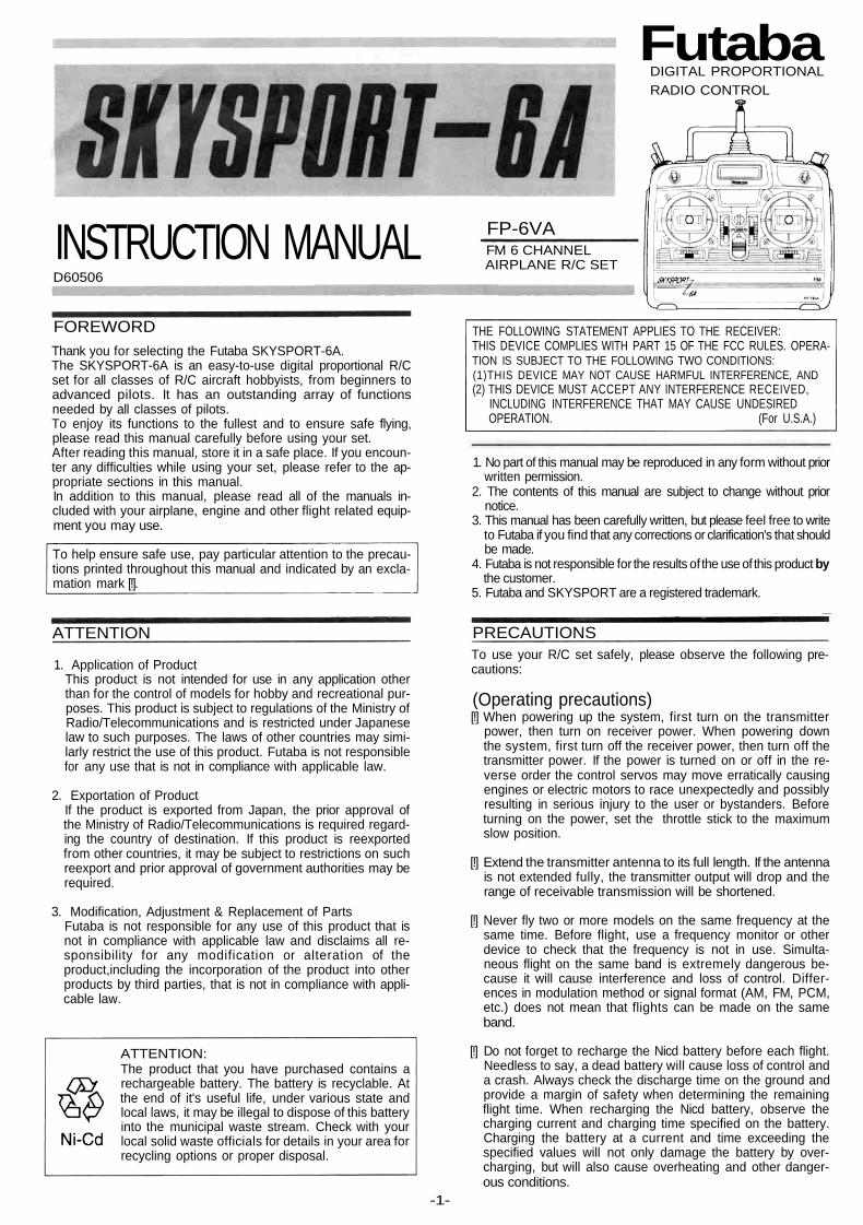
INSTRUCTION MANUALD60506
FOREWORDThank you for selecting the Futaba SKYSPORT-6A.The SKYSPORT-6A is an easy-to-use digital proportional R/Cset for all classes of R/C aircraft hobbyists, from beginners toadvanced pilots. It has an outstanding array of functionsneeded by all classes of pilots.To enjoy its functions to the fullest and to ensure safe flying,please read this manual carefully before using your set.After reading this manual, store it in a safe place. If you encoun-ter any difficulties while using your set, please refer to the ap-propriate sections in this manual.In addition to this manual, please read all of the manuals in-cluded with your airplane, engine and other flight related equip-ment you may use.
To help ensure safe use, pay particular attention to the precau-tions printed throughout this manual and indicated by an excla-mation mark [!].
FutabaDIGITAL PROPORTIONALRADIO CONTROL
FP-6VAFM 6 CHANNELAIRPLANE R/C SET
THE FOLLOWING STATEMENT APPLIES TO THE RECEIVER:THIS DEVICE COMPLIES WITH PART 15 OF THE FCC RULES. OPERA-TION IS SUBJECT TO THE FOLLOWING TWO CONDITIONS:(1)THIS DEVICE MAY NOT CAUSE HARMFUL INTERFERENCE, AND(2) THIS DEVICE MUST ACCEPT ANY INTERFERENCE RECEIVED,
INCLUDING INTERFERENCE THAT MAY CAUSE UNDESIREDOPERATION. (For U.S.A.)
1. No part of this manual may be reproduced in any form without priorwritten permission.
2. The contents of this manual are subject to change without priornotice.
3. This manual has been carefully written, but please feel free to writeto Futaba if you find that any corrections or clarification's that shouldbe made.
4. Futaba is not responsible for the results of the use of this product bythe customer.
5. Futaba and SKYSPORT are a registered trademark.
ATTENTION PRECAUTIONS
1. Application of ProductThis product is not intended for use in any application otherthan for the control of models for hobby and recreational pur-poses. This product is subject to regulations of the Ministry ofRadio/Telecommunications and is restricted under Japaneselaw to such purposes. The laws of other countries may simi-larly restrict the use of this product. Futaba is not responsiblefor any use that is not in compliance with applicable law.
2. Exportation of ProductIf the product is exported from Japan, the prior approval ofthe Ministry of Radio/Telecommunications is required regard-ing the country of destination. If this product is reexportedfrom other countries, it may be subject to restrictions on suchreexport and prior approval of government authorities may berequired.
3. Modification, Adjustment & Replacement of PartsFutaba is not responsible for any use of this product that isnot in compliance with applicable law and disclaims all re-sponsibility for any modification or alteration of theproduct,including the incorporation of the product into otherproducts by third parties, that is not in compliance with appli-cable law.
ATTENTION:The product that you have purchased contains arechargeable battery. The battery is recyclable. Atthe end of it's useful life, under various state andlocal laws, it may be illegal to dispose of this batteryinto the municipal waste stream. Check with yourlocal solid waste officials for details in your area forrecycling options or proper disposal.
To use your R/C set safely, please observe the following pre-cautions:
(Operating precautions)[!] When powering up the system, first turn on the transmitter
power, then turn on receiver power. When powering downthe system, first turn off the receiver power, then turn off thetransmitter power. If the power is turned on or off in the re-verse order the control servos may move erratically causingengines or electric motors to race unexpectedly and possiblyresulting in serious injury to the user or bystanders. Beforeturning on the power, set the throttle stick to the maximumslow position.
[!] Extend the transmitter antenna to its full length. If the antennais not extended fully, the transmitter output will drop and therange of receivable transmission will be shortened.
[!] Never fly two or more models on the same frequency at thesame time. Before flight, use a frequency monitor or otherdevice to check that the frequency is not in use. Simulta-neous flight on the same band is extremely dangerous be-cause it will cause interference and loss of control. Differ-ences in modulation method or signal format (AM, FM, PCM,etc.) does not mean that flights can be made on the sameband.
[!] Do not forget to recharge the Nicd battery before each flight.Needless to say, a dead battery will cause loss of control anda crash. Always check the discharge time on the ground andprovide a margin of safety when determining the remainingflight time. When recharging the Nicd battery, observe thecharging current and charging time specified on the battery.Charging the battery at a current and time exceeding thespecified values will not only damage the battery by over-charging, but will also cause overheating and other danger-ous conditions.
-1-
[!] Do not fly on rainy days. Even in a drizzle, water can enter thetransmitter through the antenna and sticks and cause faultyoperation. The resulting loss of control may cause a crash orthe engine to race and is very dangerous.
[!] When placing the transmitter on the ground during flightpreparations, make certain that the transmitter cannot beeasily toppled by the wind or other means. If it tips over whilethe engine is running and the throttle stick is inadvertentlymoved to the high position as result, serious injury to the op-erator or others could result.
[!] Always test your digital proportional R/C set before flight. Asa simple test method, before starting the engine, retract thetransmitter antenna fully and operate each servo from a dis-tance of about 5m and check if the servos follow the move-ment of their control sticks. If a servo does not follow themovement of its control stick, extend the transmitter antennato its full length, increase the distance on the ground, andrepeat the test. If the receiving range is still short, discontinueflight and check the set.
(Flying field)[!] In general, when a model is flown at high speed and / or the
flying range is large, even more caution is necessary. A safemethod is to fly at an exclusive flying field belonging to a club,etc. However, the presence of spectators, wind direction, etc.must be constantly monitored. In areas near high tensionlines, high buildings, and communication facilities, consider-ation must be given not only to normal flight dangers, but alsoto possible loss of control caused by radio wave interference.Because R/C radio waves have a fairly long range, a locationat least 3 km / 2 miles from other R/C flying fields and R/Ccontrol circuits is necessary.
SET CONTENTS
Set nameTransmitterReceiverServosBattery
(Transmitter)Battery(Receiver)Battery chargerOthers
SKYSPORT-6AFP-T6VA
FP-R116FB, FP-R138DF, or FP-R127DFFP-S3001x4orFP-S148x4
NT-8iB
NR-4J
x1Receiver switch, Extension cord,Servo horns, Flat screwdriver
RATINGS
Transmitter FP-T6VAOperating system: Two-stick, 6 channels, w/airplane functionTransmitting frequency: 29, 35. 36, 40, 41, 50, 60 or 72MHz bandModulation: FM (Frequency Modulation)Power requirement: 9.6V Nicd battery(NT-8iB)Current drain: 180mA
Receiver FP-R116FBReceiving frequency: 29, 35. 36. 40, 41 or 60MHz bandIntermediate frequency: 455kHzPower requirement: 4.8V or 6V Nicd battery (shared with servos)Current drain: 22mASize: 33.4X50.4X20.5mmWeight: 30g/1.06oz
Receiver FP-R138DFReceiving frequency: 35MHz bandIntermediate frequency: 1st IF 10.7MHz. 2nd IF 455kHzPower requirement: 4.8V or 6V Nicd battery (shared with servos)Current drain: 12mASize: 65X36X21,5mmWeight: 39g/1.38oz
Receiver FP-R127DFReceiving frequency: 50 or 72MHz bandIntermediate frequency: 1 st IF 10.7MHz, 2nd IF 455kHzPower requirement: 4.8V or 6V Nicd battery (shared with servos)Current drain: 10mASize: 64.3X35.8X21.0mmWeight; 40.5g /1.43oz
Servo FP-S3001/FP-S148Control system: Pulse width controlOperating angle: One side 45 degree min. (including trim)Power requirement: 4.8V or 6V Nicd battery (shared with receiver)Current drain: 8mA (at idle)Output torque: 3kg-cm / 42oz-inOperating speed: 0.22 sec/60 degreeSize: 40.4x19.8x36mmWeight: 45.1g / 1.59oz(S3001),44.4g/ 1.57oz(S148)
Nicd battery NT-8JBVoltage: 9.6VCapacity: 500mAh
Nicd battery NR-4JVoltage: 4.8VCapacity: 500mAhDimensions: 51x58x15rWeight; 95g/3.35oz
Product Support(Do Not Remove From Department)
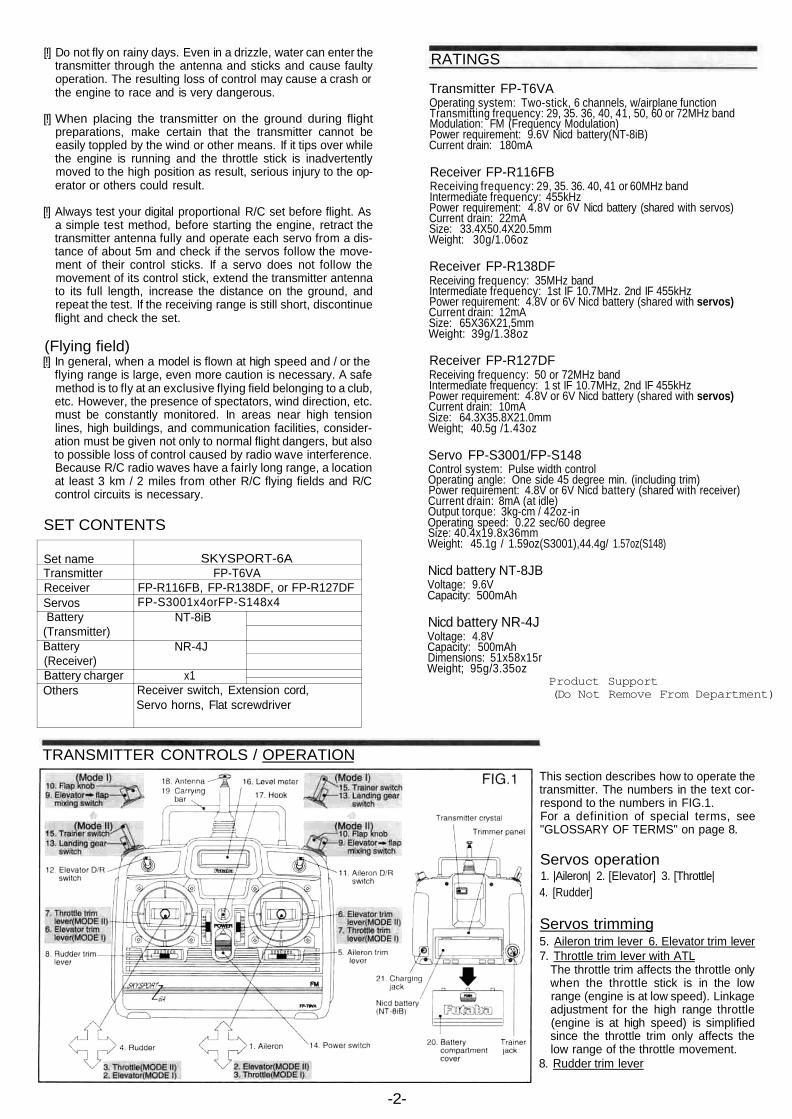
TRANSMITTER CONTROLS / OPERATION
-2-
This section describes how to operate thetransmitter. The numbers in the text cor-respond to the numbers in FIG.1.For a definition of special terms, see"GLOSSARY OF TERMS" on page 8.
Servos operation1. |Aileron| 2. [Elevator] 3. [Throttle|4. [Rudder]
Servos trimming5. Aileron trim lever 6. Elevator trim lever7. Throttle trim lever with ATL
The throttle trim affects the throttle onlywhen the throttle stick is in the lowrange (engine is at low speed). Linkageadjustment for the high range throttle(engine is at high speed) is simplifiedsince the throttle trim only affects thelow range of the throttle movement.
8. Rudder trim lever

Switches and knobs9. Elevator -> flap mixing switch (ELV -> FLP)
When this switch if pulled forward, the mixing function isturned on and the flaps are linked with elevator operation.However, this switch is effective only when elevator -> flapmixing is active (ACT).
10. Flap knob (FLAP)Normally, this knob is used as CH6. When flaperon mixing isactive (ACT), this knob acts as the flap trimmer.
11. aileron dual rate switch (AILERON D/R)This switch toggles the aileron servo travel (RATE1 ,RATE2). RATE1; upper position RATE2; down position
12. Elevator dual rate switch (ELEVATOR D/R)This switch toggles the elevator servo travel (RATE1,RATE2). RATE1; upper position RATE2; down position
13. Landing gear switch (GEAR)This switch activates the landing gear channel. (CH5 switch)
14. Power switchThe transmitter is turned on when this switch is set to theupper position.
15. Trainer switch (TRAINER)This switch is turned on when set to the pulled forward posi-tion (spring-loaded type).
Others16. Level meter[!] This meter indicates the transmitter power supply voltage.
When the needle deflects to the boundary between the silverand red ranges, recharge the Nicd battery.
17. HookHook for neck strap.
18. Antenna[!] When using the transmitter, extend the antenna to its full
length.19. Carrying bar
Use this handle to carry the transmitter.20. Battery cover
Open this cover when adjusting the trimmers on the trimmerpanel and when changing the Nicd battery.
21. Charging jackThis is the transmitter Nicd battery charging jack.
(Charging the Nicd battery)[!] Never try to charge a dry cell battery. It will cause the battery
to overheat or explode and is very dangerous.[!] Always charge the Nicd battery before using your R/C set.
Connect the charger's transmit-ter and receiver connectors tothe transmitter charging jack andreceiver servo Nicd battery asshown in the figure(FIG.2). Thecharging LEDs light to show thatthe battery is being charged.
* The normal charging time isabout 15 hours. When you havenot used your R/C set for sometime, repeatedly charge and dis-charge the batteries two or threetimes before use.
* The transmitter and receiver Nicd batteries can be chargedsimultaneously or independently.
(Non-slip adjustable lever head)The length of the lever headof the sticks can be adjustedas desired. Adjust the sticklength to fit your hand. (FIG.3)1) Unlock lever heads A and B
by turning them in the direc-tions shown by the arrows.
2) Adjust the stick to the most comfortable length and lock it byturning head B in the directions opposite that shown by thearrow.
(Stick lever spring tension adjustment)The stick lever springtension can be adjustedby removing the trans-mitter back cover andturning the screw foreach stick as shown inthe figure (FIG.4). Adjustthe spring tension for thebest stick feel. When ad-justing the stick spring,set the throttle stick to thecenter.
(Trimmer panel)
a. Servo reversing switch (SERVO REVERSER)The servo reversing switches reverse the direction of travel ofthe servos. The lower position is the normal position.(Channels 1 to 6) (DIP switch Nos. 1 to 6)
b. Mode switches1. Elevator -> flap mixing ACT/INH switch
To activate the mixing function, set this switch to the ACT(upper) position. To deactivate the mixing function, set thisswitch to the INH (lower) position. (DIP switch No. 7)
2. Flaperon mixing ACT/INH switchTo activate the mixing function, set this switch to the ACT(upper) position. To deactivate the mixing function, set thisswitch to the INH (lower) position. (DIP switch No. 8)
3. Rudder AST function ACT/INH switchTo activate the rudder and throttle AST functions, set thisswitch to the ACT (upper) position. The throttle ATV func-tion can be activated by setting this switch to the INH(lower) position. Select the desired function.
c. Aileron dual rate trimmer (AIL D/R)This trimmer sets the rate corresponding to both directions ofthe aileron dual rate switch. (RATE1, RATE2)When it is turned clockwise, the servo travel increases.
d. Elevator dual rate trimmer (ELV D/R)This trimmer sets the rate corresponding to both directions ofthe elevator dual rate switch. (RATE 1, RATE2)When it is turned clockwise, the servo travel increases.
e. Throttle AST trimmer (TH.AST) or throttle ATV trimmer(TH.ATV) H sideThis trimmer adjusts the servo travel of the selected function.When it is turned clockwise, the servo travel increases.
f. Rudder AST trimmer (RUD.AST) or Throttle ATV trimmer(TH.ATV) L sideThis trimmer adjusts the servo travel of the selected function.When it is turned clockwise, the servo travel increases.
g. Aileron differential trimmer (DIFF.RATE)This trimmer adjusts the aileron differential amount when theflaperon mixing function is active.
h. EIevator -> flap mixing trimmer (ELV->FLP)This trimmer adjusts the mixing operation direction andamount.
i. Flap trimming function trimmer (FLP.TRIM)This trimmer adjusts the flap trimming operation direction andvariation width when the flaperon mixing function is active.
-3-
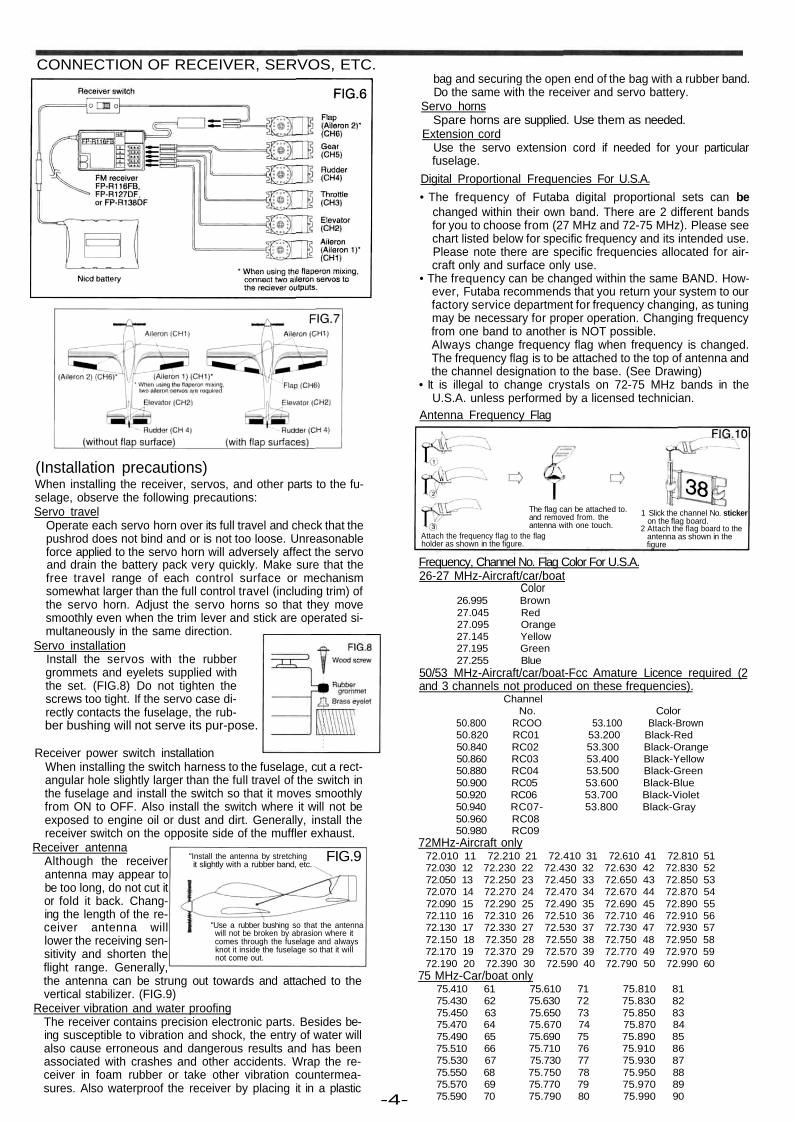
CONNECTION OF RECEIVER, SERVOS, ETC.
FIG.9
(Installation precautions)When installing the receiver, servos, and other parts to the fu-selage, observe the following precautions:Servo travel
Operate each servo horn over its full travel and check that thepushrod does not bind and or is not too loose. Unreasonableforce applied to the servo horn will adversely affect the servoand drain the battery pack very quickly. Make sure that thefree travel range of each control surface or mechanismsomewhat larger than the full control travel (including trim) ofthe servo horn. Adjust the servo horns so that they movesmoothly even when the trim lever and stick are operated si-multaneously in the same direction.
Servo installationInstall the servos with the rubbergrommets and eyelets supplied withthe set. (FIG.8) Do not tighten thescrews too tight. If the servo case di-rectly contacts the fuselage, the rub-ber bushing will not serve its pur-pose.
Receiver power switch installationWhen installing the switch harness to the fuselage, cut a rect-angular hole slightly larger than the full travel of the switch inthe fuselage and install the switch so that it moves smoothlyfrom ON to OFF. Also install the switch where it will not beexposed to engine oil or dust and dirt. Generally, install thereceiver switch on the opposite side of the muffler exhaust.
Receiver antennaAlthough the receiverantenna may appear tobe too long, do not cut itor fold it back. Chang-ing the length of the re-ceiver antenna willlower the receiving sen-sitivity and shorten theflight range. Generally,
"Install the antenna by stretchingit slightly with a rubber band, etc.
the antenna can be strung out towards and attached to thevertical stabilizer. (FIG.9)
Receiver vibration and water proofingThe receiver contains precision electronic parts. Besides be-ing susceptible to vibration and shock, the entry of water willalso cause erroneous and dangerous results and has beenassociated with crashes and other accidents. Wrap the re-ceiver in foam rubber or take other vibration countermea-sures. Also waterproof the receiver by placing it in a plastic
"Use a rubber bushing so that the antennawill not be broken by abrasion where itcomes through the fuselage and alwaysknot it inside the fuselage so that it willnot come out.
-4-
bag and securing the open end of the bag with a rubber band.Do the same with the receiver and servo battery.
Servo hornsSpare horns are supplied. Use them as needed.
Extension cordUse the servo extension cord if needed for your particularfuselage.
Digital Proportional Frequencies For U.S.A.• The frequency of Futaba digital proportional sets can be
changed within their own band. There are 2 different bandsfor you to choose from (27 MHz and 72-75 MHz). Please seechart listed below for specific frequency and its intended use.Please note there are specific frequencies allocated for air-craft only and surface only use.
• The frequency can be changed within the same BAND. How-ever, Futaba recommends that you return your system to ourfactory service department for frequency changing, as tuningmay be necessary for proper operation. Changing frequencyfrom one band to another is NOT possible.Always change frequency flag when frequency is changed.The frequency flag is to be attached to the top of antenna andthe channel designation to the base. (See Drawing)
• It is illegal to change crystals on 72-75 MHz bands in theU.S.A. unless performed by a licensed technician.
Antenna Frequency Flag
The flag can be attached to.and removed from. theantenna with one touch.
Attach the frequency flag to the flagholder as shown in the figure.
1 Slick the channel No. stickeron the flag board.
2 Attach the flag board to theantenna as shown in thefigure
Frequency, Channel No. Flag Color For U.S.A.26-27 MHz-Aircraft/car/boat
Color26.995 Brown27.045 Red27.095 Orange27.145 Yellow27.195 Green27.255 Blue
50/53 MHz-Aircraft/car/boat-Fcc Amature Licence required (2and 3 channels not produced on these frequencies).
ChannelNo. Color
50.800 RCOO 53.100 Black-Brown50.820 RC01 53.200 Black-Red50.840 RC02 53.300 Black-Orange50.860 RC03 53.400 Black-Yellow50.880 RC04 53.500 Black-Green50.900 RC05 53.600 Black-Blue50.920 RC06 53.700 Black-Violet50.940 RC07- 53.800 Black-Gray50.960 RC0850.980 RC09
72MHz-Aircraft only72.010 11 72.210 21 72.410 31 72.610 41 72.810 5172.030 12 72.230 22 72.430 32 72.630 42 72.830 5272.050 13 72.250 23 72.450 33 72.650 43 72.850 5372.070 14 72.270 24 72.470 34 72.670 44 72.870 5472.090 15 72.290 25 72.490 35 72.690 45 72.890 5572.110 16 72.310 26 72.510 36 72.710 46 72.910 5672.130 17 72.330 27 72.530 37 72.730 47 72.930 5772.150 18 72.350 28 72.550 38 72.750 48 72.950 5872.170 19 72.370 29 72.570 39 72.770 49 72.970 5972.190 20 72.390 30 72.590 40 72.790 50 72.990 60
75 MHz-Car/boat only75.410 61 75.610 71 75.810 8175.430 62 75.630 72 75.830 8275.450 63 75.650 73 75.850 8375.470 64 75.670 74 75.870 8475.490 65 75.690 75 75.890 8575.510 66 75.710 76 75.910 8675.530 67 75.730 77 75.930 8775.550 68 75.750 78 75.950 8875.570 69 75.770 79 75.970 8975.590 70 75.790 80 75.990 90
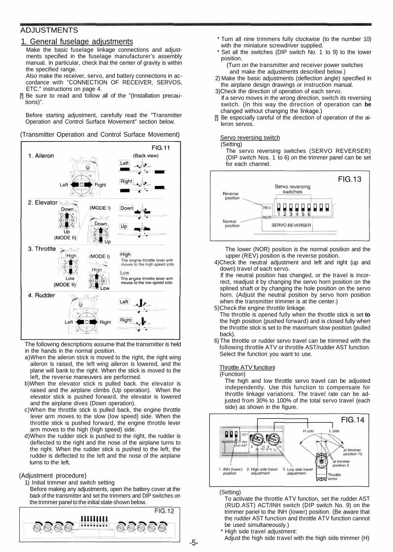
ADJUSTMENTS1. General fuselage adjustments
Make the basic fuselage linkage connections and adjust-ments specified in the fuselage manufacturer's assemblymanual. In particular, check that the center of gravity is withinthe specified range.Also make the receiver, servo, and battery connections in ac-cordance with "CONNECTION OF RECEIVER, SERVOS,ETC." instructions on page 4.
[!] Be sure to read and follow all of the "(Installation precau-tions)".
Before starting adjustment, carefully read the "TransmitterOperation and Control Surface Movement" section below.
(Transmitter Operation and Control Surface Movement)
The following descriptions assume that the transmitter is heldin the hands in the normal position.a)When the aileron stick is moved to the right, the right wing
aileron is raised, the left wing aileron is lowered, and theplane will bank to the right. When the stick is moved to theleft, the reverse maneuvers are performed.
b)When the elevator stick is pulled back. the elevator israised and the airplane climbs (Up operation). When theelevator stick is pushed forward, the elevator is loweredand the airplane dives (Down operation).
c)When the throttle stick is pulled back, the engine throttlelever arm moves to the slow (low speed) side. When thethrottle stick is pushed forward, the engine throttle leverarm moves to the high (high speed) side.
d)When the rudder stick is pushed to the right, the rudder isdeflected to the right and the nose of the airplane turns tothe right. When the rudder stick is pushed to the left, therudder is deflected to the left and the nose of the airplaneturns to the left.
(Adjustment procedure)1) Initial trimmer and switch setting
Before making any adjustments, open the battery cover at theback of the transmitter and set the trimmers and DIP switches onthe trimmer panel to the initial state shown below.
* Turn all nine trimmers fully clockwise (to the number 10)with the miniature screwdriver supplied.
* Set all the switches (DIP switch No. 1 to 9) to the lowerposition.
(Turn on the transmitter and receiver power switchesand make the adjustments described below.)
2) Make the basic adjustments (deflection angle) specified inthe airplane design drawings or instruction manual.
3)Check the direction of operation of each servo.If a servo moves in the wrong direction, switch its reversingswitch. (In this way the direction of operation can bechanged without changing the linkage.)
[!] Be especially careful of the direction of operation of the ai-leron servos.
Servo reversing switch(Setting)
The servo reversing switches (SERVO REVERSER)(DIP switch Nos. 1 to 6) on the trimmer panel can be setfor each channel.
The lower (NOR) position is the normal position and theupper (REV) position is the reverse position.
4)Check the neutral adjustment and left and right (up anddown) travel of each servo.If the neutral position has changed, or the travel is incor-rect, readjust it by changing the servo horn position on thesplined shaft or by changing the hole position on the servohorn. (Adjust the neutral position by servo horn positionwhen the transmitter trimmer is at the center.)
5)Check the engine throttle linkage.The throttle is opened fully when the throttle stick is set tothe high position (pushed forward) and is closed fully whenthe throttle stick is set to the maximum slow position (pulledback).
6) The throttle or rudder servo travel can be trimmed with thefollowing throttle ATV or throttle AST/rudder AST function.Select the function you want to use.
Throttle ATV functioni(Function)
The high and low throttle servo travel can be adjustedindependently. Use this function to compensate forthrottle linkage variations. The travel rate can be ad-justed from 30% to 100% of the total servo travel (eachside) as shown in the figure.
(Setting)To activate the throttle ATV function, set the rudder AST(RUD.AST) ACT/INH switch (DIP switch No. 9) on thetrimmer panel to the INH (lower) position. (Be aware thatthe rudder AST function and throttle ATV function cannotbe used simultaneously.)
* High side travel adjustment:Adjust the high side travel with the high side trimmer (H)
-5-
of the TH.ATV trimmers on the trimmer panel. Adjust thehigh side travel to between high side trimmer positions 0(30%) and 10(100%).
* Low side travel adjustment:Adjust the low side travel with the low side trimmer (L) ofthe TH.ATV trimmers on the trimmer panel. Adjust thelow side travel between low side trimmer positions 0(30%) and 10(100%).
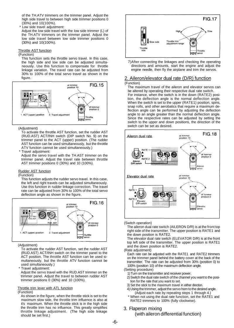
Throttle AST function(Function)
This function sets the throttle servo travel. In this case,the high side and low side can be adjusted simulta-neously. Use this function to compensate for throttlelinkage variation. The travel rate can be adjusted from30% to 100% of the total servo travel as shown in thefigure.
(Adjustment)To activate the throttle AST function, set the rudder AST(RUD.AST) ACT/INH switch (DIP switch No. 9) on thetrimmer panel to the ACT (upper) position. (The rudderAST function can be used simultaneously, but the throttleATV function cannot be used simultaneously.)
* Travel adjustment:Adjust the servo travel with the TH.AST trimmer on thetrimmer panel. Adjust the travel rate between throttleAST trimmer positions 0 (30%) and 10 (100%).
Rudder AST function(Function)
This function adjusts the rudder servo travel. In this case,the left and right travels can be adjusted simultaneously.Use this function in rudder linkage correction. The travelrate can be adjusted from 30% to 100% of the total servodeflection angle as shown in the figure.
(Adjustment)To activate the rudder AST function, set the rudder AST(RUD.AST) ACT/INH switch on the trimmer panel to theACT position. The throttle AST function can be used si-multaneously, but the throttle ATV function cannot beused simultaneously.)
* Travel adjustment:Adjust the servo travel with the RUD.AST trimmer on thetrimmer panel. Adjust the travel to between rudder ASTtrimmer positions 0 (30%) and 10 (100%).
Throttle trim lever with ATL function(Function)
As shown in the figure, when the throttle stick is set to themaximum slow side, the throttle trim influence is also atit's maximum. When the throttle stick is in the high sidethe throttle trim has no influence. This greatly simplifiesthrottle linkage adjustment. (The high side linkageshould be set first.)
7)After connecting the linkages and checking the operatingdirections and amounts, start the engine and adjust theengine needle, then fly the airplane and trim the servos.
2. Aileron/elevator dual rate (D/R) function(Function)
The maximum travel of the aileron and elevator servos canbe altered by operating their respective dual rate switch.For instance, when the switch is in the down (RATE2) posi-tion, the deflection angle is the normal deflection angle.When the switch is set to the upper (RATE1) position, spins,snap rolls, and other aerobatics that require a maximum de-flection angle can be performed by adjusting the deflectionangle to an angle greater than the normal deflection angle.Since the respective rates can be adjusted by setting theswitch to the upper and down positions, the direction of theswitch can be set as desired.
(Switch operation)The aileron dual rate switch (AILERON D/R) is at the front topright side of the transmitter. The upper position is RATE1 andthe down position is RATE2.The elevator dual rate switch (ELEVATOR D/R) is at the fronttop left side of the transmitter. The upper position is RATE1and the down position is RATE2.
(Rate adjustment)Each rate can be adjusted with the RATE1 and RATE2 trimmerson the trimmer panel behind the battery cover at the back of thetransmitter. The rate can be adjusted from 30% (position 0) to100% (position 10) of the maximum deflection angle.
(Setting procedure)1) Turn on the transmitter and receiver power.2) Switch the dual rate switch of the channel you want to the posi-
tion for the rate that you want to set.3) Set the stick to the maximum travel in either direction.4) Using the trimmer, adjust the servo horn to the desired angle.
(Adjust each rate by repeating steps 1 through 4.)* When not using the dual rate function, set the RATE1 and
RATE2 trimmers to 100% (fully clockwise).
3. Flaperon mixing(with aileron differential function)
-6-
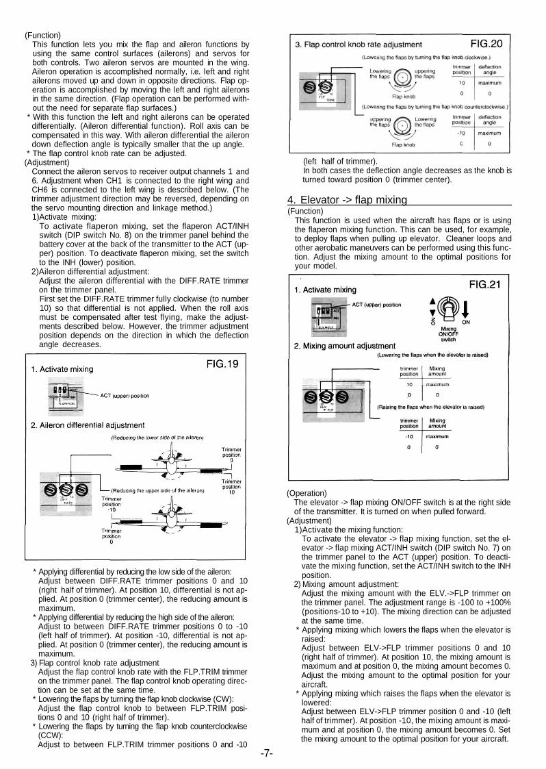
(Function)This function lets you mix the flap and aileron functions byusing the same control surfaces (ailerons) and servos forboth controls. Two aileron servos are mounted in the wing.Aileron operation is accomplished normally, i.e. left and rightailerons moved up and down in opposite directions. Flap op-eration is accomplished by moving the left and right aileronsin the same direction. (Flap operation can be performed with-out the need for separate flap surfaces.)
* With this function the left and right ailerons can be operateddifferentially. (Aileron differential function). Roll axis can becompensated in this way. With aileron differential the ailerondown deflection angle is typically smaller that the up angle.
* The flap control knob rate can be adjusted.(Adjustment)
Connect the aileron servos to receiver output channels 1 and6. Adjustment when CH1 is connected to the right wing andCH6 is connected to the left wing is described below. (Thetrimmer adjustment direction may be reversed, depending onthe servo mounting direction and linkage method.)1)Activate mixing:
To activate flaperon mixing, set the flaperon ACT/INHswitch (DIP switch No. 8) on the trimmer panel behind thebattery cover at the back of the transmitter to the ACT (up-per) position. To deactivate flaperon mixing, set the switchto the INH (lower) position.
2)Aileron differential adjustment:Adjust the aileron differential with the DIFF.RATE trimmeron the trimmer panel.First set the DIFF.RATE trimmer fully clockwise (to number10) so that differential is not applied. When the roll axismust be compensated after test flying, make the adjust-ments described below. However, the trimmer adjustmentposition depends on the direction in which the deflectionangle decreases.
* Applying differential by reducing the low side of the aileron:Adjust between DIFF.RATE trimmer positions 0 and 10(right half of trimmer). At position 10, differential is not ap-plied. At position 0 (trimmer center), the reducing amount ismaximum.
* Applying differential by reducing the high side of the aileron:Adjust to between DIFF.RATE trimmer positions 0 to -10(left half of trimmer). At position -10, differential is not ap-plied. At position 0 (trimmer center), the reducing amount ismaximum.
3) Flap control knob rate adjustmentAdjust the flap control knob rate with the FLP.TRIM trimmeron the trimmer panel. The flap control knob operating direc-tion can be set at the same time.
* Lowering the flaps by turning the flap knob clockwise (CW):Adjust the flap control knob to between FLP.TRIM posi-tions 0 and 10 (right half of trimmer).
* Lowering the flaps by turning the flap knob counterclockwise(CCW):Adjust to between FLP.TRIM trimmer positions 0 and -10
(left half of trimmer).In both cases the deflection angle decreases as the knob isturned toward position 0 (trimmer center).
4. Elevator -> flap mixing(Function)
This function is used when the aircraft has flaps or is usingthe flaperon mixing function. This can be used, for example,to deploy flaps when pulling up elevator. Cleaner loops andother aerobatic maneuvers can be performed using this func-tion. Adjust the mixing amount to the optimal positions foryour model.
(Operation)The elevator -> flap mixing ON/OFF switch is at the right sideof the transmitter. It is turned on when pulled forward.
(Adjustment)1)Activate the mixing function:
To activate the elevator -> flap mixing function, set the el-evator -> flap mixing ACT/INH switch (DIP switch No. 7) onthe trimmer panel to the ACT (upper) position. To deacti-vate the mixing function, set the ACT/INH switch to the INHposition.
2) Mixing amount adjustment:Adjust the mixing amount with the ELV.->FLP trimmer onthe trimmer panel. The adjustment range is -100 to +100%(positions-10 to +10). The mixing direction can be adjustedat the same time.
* Applying mixing which lowers the flaps when the elevator israised:Adjust between ELV->FLP trimmer positions 0 and 10(right half of trimmer). At position 10, the mixing amount ismaximum and at position 0, the mixing amount becomes 0.Adjust the mixing amount to the optimal position for youraircraft.
* Applying mixing which raises the flaps when the elevator islowered:Adjust between ELV->FLP trimmer position 0 and -10 (lefthalf of trimmer). At position -10, the mixing amount is maxi-mum and at position 0, the mixing amount becomes 0. Setthe mixing amount to the optimal position for your aircraft.
-7-
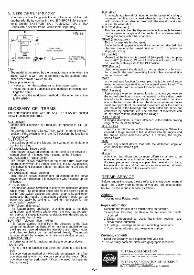
5. Using the trainer functionYou can practice flying with the aid of another pilot or helpanother pilot fly by connecting the SKYSPORT-6A transmit-ter to another SKYSPORT-6A , PCM1024Z, 7UA, or 5UASeries with a special trainer cable (sold separately).
(Use)The model is controlled by the instructor transmitter when thetrainer switch is OFF and is controlled by the student trans-mitter when trainer switch to ON.
(Usage precautions)* Never turn on the student transmitter power switch.* Make the student transmitter and instructor transmitter set-
tings the same.* Make sure the modulation method of the other transmitter
is FM (PPM).
GLOSSARY OF TERMSThe abbreviations used with the SKYSPORT-6A are definedbelow in alphabetical order.
ACT (activate)Means that a function is turned on. Its opposite is INH (in-hibit).To activate a function, its ACT/INH switch is set to the ACTposition. If the switch is not in the ACT position, the function isnot activated^
AILERON/AIL.An auxiliary airfoil at the left and right wings of an airplane tocontrol its rolling.
AST (Adjustable Servo travel)This feature allows adjustment of the travel of the servo of acertain channel. It is used when setting up the linkages.
ATL (Adjustable Throttle Limit)This feature allows movement of the throttle trim lever thatoperates only when the throttle stick is in the SLOW position.It is convenient because it does not affect the HIGH side ofthe throttle.
ATV (Adjustable Travel Volume)This feature allows independent adjustment of the servotravel in each direction. It is convenient when setting up thelinkages.
D/R (Dual Rate)This function allows switching to one of two deflection angleswhile flying. The deflection angle best for the aircraft can beset for one switch position and spins, snap rolls, and otheraerobatics that require a maximum deflection angle can beperformed easily by setting up maximum deflection for theother switch position.
DIFF. (aileron differential)This feature allows application of a differential to the rightwing aileron and left wing aileron when the wing has two aile-ron servos. It is used to correct undesirable tendencies and tocompensate the roll axis.
ELV.->FLP. (elevator->flap mixing)This feature applies mixing from the elevators to the flapswhen the fuselage has flaps. When mixing is applied so thatthe flaps are lowered when the elevators are raised, loopsand other aerobatics can be performed cleanly. The mixingamount should be adjusted optimally for individual aircraft.
ELEVATOR / ELV.A horizontal airfoil for making an airplane go up or down.
FLAPERONThis is a mixing function that gives the ailerons a flap func-tion.It is a convenient method of mixing aileron operation and flapoperation using only two aileron servos at the wings. (Flapoperation can be performed without the need for separateflap surfaces.)
FLP. (Flap)A movable auxiliary airfoil attached to the center of a wing toincrease the lift at slow speed when taking off and landing.With models it can also be mixed with the elevator and usedin circular aerobatics.
FLP.TRIM (Flap trim)This feature switches the flap servo deflection angle betweennormal operating angle and trim angle. It is convenient whenmixing the flaps with other channels.
GEAR (Landing gear)This is for airplane landing gear.Since the landing gear is normally extended or retracted, thischannel can only be turned fully on or off. It cannot bestopped midway.
INH (Inhibit)Means that the function is turned off (stopped). It is the oppo-site of ACT (activate). When a function is not used, its ACT/INH switch is always set to the INH position.
NOR (Normal)Used to represent the default or normal state of a function.For example, the servo reversing function has a normal sideand a reverse side.
RATEIn the dual rate function for example, this is the rate of servotravel in percentage relative to the normal servo travel. Therate is adjusted with a trimmer for each function.
REV (Reverse)Represents the servo reversing function that lets you reversethe normal direction of servo movement, or the setting posi-tion of a switch (reverse position). It is used when the direc-tion of the transmitter stick and the direction of servo move-ment are opposite of the desired movement after the servosare mounted in the fuselage and each airfoil and servo areconnected by pushrods, etc. The direction of movement canbe corrected without changing the linkage.
RUD (Rudder)A hinged directional surface attached to the vertical trailingedge of the tail of an aircraft.
TH (Throttle)Used to controls the fuel at the intake of an engine. When it isopened, a large amount of fuel is drawn into the engine andthe engine speed increases. When it is closed, the enginespeed slows.
TRIMA fine adjustment device that sets the deflection angle ofeach airfoil for stable flight.
(OTHERS)Mixing
A function that allows two or more different channels to beoperated together in a linked or dependent manner.For example, when mixing is applied from elevators to flaps,the elevator servo and flap servo can be operated simulta-neously by operation of the elevator stick.
REPAIR SERVICEBefore requesting repair, please refer to this instruction manualagain and verify your settings. If you are still experiencingtrouble, please request service as follows:
AddressYour nearest Futaba dealer.
Repair informationDescribe the trouble in as much detail as possible.1)Symptom: Including the state of the set when the trouble
occurred.2) Digital proportional set used: Transmitter, receiver, and
servo model numbers.3) Fuselage: Fuselage name and mounting conditions.4) Your name, address, and telephone number.
Warranty contentsRead the warranty card supplied with your set.
* The warranty contents differ with geographic locations.
FUTABA CORPORATIONMakuhari Techno Garden BIdg.. B6F I -3 Nakase. Mihama-ku. Chiba 261-01. JapanPhone: (043) 296-5119 Facsimile: (043) 296-5124
FUTABA CORPORATION OF AMERICA4 Studebaker. Irvine California 92718, U.S.A.Phone: 714-455-9888 Telex: 23-0691227 Facsimile: 714-455-9899
-8-