Embed Size (px)
Citation preview

585
A
B
C
G
9,8
K
F
D
E
I
J
H
A
B
C
G
9,8
K
F
D
E
I
J
H
k
l
l
m s1
TIP k l m s1
00C 0 20.7 16.7 7.5
00 0 20.7 16.7 7.5
1 13.7 19.7 25 12
2 16.2 27.4 25 12
3 17 35.6 25 12
4a 24 49 25 12 S1M
K
LL
400 V AC, 500 V AC, 690 V AC2 - 1600 A120 kA, 100 kA, 50 kAgG, aM, gF, gTr DIN VDE0636-201 (1998-06)IEC 60269-1:2005 / EN 60269-1:1998+A1:2005IEC 60269-2:1986+Corr.1:1996+A11995+A2:2001 / EN 60269-2:1995+A1:1998+A2:2002IEC 60269-2-1:2004 / HD 60269-2-1:2005 DIN43620 Part: 1 - 4
A B C D E F G H I J KNV00C 79 53 47 35 15 21 52 7,5 6 kombiNV00C I 79 53 47 35 15 21 52 7,5 6 kombiNV00 79 53 47 35 15 28 56 12 6 kombiNV00 I 79 53 47 35 15 28 56 12 6 kombiNV0 125 68 65 35 15 28 56 12 6 kombiNV1C 135 68 65 40 15 28 61 12 6 kombiNV1C I 135 68 65 40 15 28 61 12 6 kombiNV1 135 72 65 40 20 46 65 14 6 kombiNV1 I 135 72 65 40 20 46 65 14 6 kombiNV2C 150 72 65 48 20 46 73 14 6 kombiNV2C I 150 72 65 48 20 46 73 14 6 kombiNV2 150 72 65 48 26 54 73 14 6 kombiNV2 I 150 72 65 48 26 54 73 14 6 kombiNV3C 150 72 65 60 26 54 84 14 6 kombiNV3 150 72 65 60 33 65 84 14 6 kombiNV4 200 75 66 87 50 100 121 24 150 16 8NV4a 200 99 87 85 50 95 121 27 6NV4a SI* 200 99 87 85 50 95 121 27 6
K L M S100C 0 20.7 16.7 7.500 0 20.7 16.7 7.51 13.7 19.7 25 122 16.2 27.4 25 123 17 35.6 25 124a 24 49 25 12
Technical data
Electrical characteristicsRated voltage Un
Rated current In
Breaking capacity Un
Melting characteristicCertifiedIn accordance with
Dimensions according toTwo versions of covers aluminium and plastic
Fuse Links NV/NH gG Dimensions
Fuse Links NV/NH
Type Dimensions
Fuse Links NV/NH gG with Striker Pin Dimensions
Type Dimensions
NV
/NH

586
-1
1064
2
-2
4
6
10
46
10
110642
210642
3
2
46
2
10
4
0
6
10
2
1
46
10
2
2
10
64
10 3
4
2
6 2A 4A 6A
480A
25A16A10A 20A 50A35A 63A
100A
2
2
40A
Ip (A)
t v (s)
4
44
10
6
-2
2
6
4
-110
2
4
6
10 0
2
6 2 4 6 2
10
2
6
10 1
4
6
6
2
2
4
10 3
2
4
6
10 4
4 6 210 2
10 3
10 4
160A125A
4
250A200A 315A 400A500A 630A 800A
710A
1000A1250A2
Ip (A)
t v (s
)
Technical data
Time current characteristics
I/t, gG
Prospective current (A)
Prea
rching
tim
e (s)
Prospective current (A)
Prea
rching
tim
e (s)
Time current characteristics
l/t, gG
Fuse-link NV/NH gG characteristics
NV
/NH

587
12501000
800630500400315250200160125100
806350403532252016
10
6
4
2
10
6
4
2
6
4
2
6
4
2
6
4
2
1
5
10 4
10 3
102
10 2 4 6 2 4 6 2 4 6 2 4 61
102
103
104
105
Ip (A)
I n (A
)
I o (A
)
280A 560A 800A300A224A
355A425A
35A
1500A710A 900A 1250A
1000A1600A
10
4
6
10-2
2
4
6
10-1
2
4
6
10
2
0
6
4
4
2
1
6
10 2
4
2
6
10 3
2
4
10
6
4
2
10 2
2 4 6 10 3
2 4 6 10 4
2 4 66Ip (A)
t v (s)
Technical data
Time current characteristics I/t, gG
(nonstandard rated currents)
Max
imum
value
of cu
rrent
(A)
Prospective current (A)
Prea
rching
tim
e (s)
Prospective current (A)
Cut-off current characteristics
NV
/NH

588
Oznaka proizvoda; Product; Produkt bezeichnung
NVaM-ikd.dwg
03.2004
RETI-ELLA/PBTekst; Text; Text
10 2 4 6
2I K
2I K
2
10
2
4
6
4063
100
5080
200
315
125
160
250
ELEKTROELEMENT
NV 00, 0, 1, 2, 3, 4aM (IEC 60269)
karakteristika odrezanega toka
program NV:
3 10 4 2 4 64 6 510
3
6
4
2
10
6
4
10 5
400
500
630
25 3516 20
710800
10001250
Cut-off current characteristic
Ip (A)
I o (A
)
I n (A
)
Oznaka proizvoda; Product; Produkt bezeichnung
NV-aM-kar.dwg
03.2007
RETI-LAB/PBTekst; Text; Text
4
410
-1
2
6 2 4 6 2
10
2
6
10 0
4
6
6
1
2
4
10 2
2
4 6 210 2
10 3
10 4
4
160A125A
100A80A
63A50A
40A200A
250A 400A315A 500A
630A
aM (VDE0636, IEC/EN 60269)
Program NV:
ELEKTROELEMENT
I/t characteristic
NV00, NV0, NV1, NV2, NV3, NV4
35A25A16A20A 32A
710A
800A1000A
1250A
Ip (A)
t v (s
)
690 V AC2-1250 A DIN 43620, IEC 60269, EN 60269 aM -> VDE 0636-2011, DIN VDE 0636100 kA
690 V AC (A) 690 V AC (W) 690 V AC (W)NV 00 160 12 9NV 1 250 32 28NV 2 400 45 41NV 3 630 60 58NV 4a 1250 105 110
Technical data
NV fuse-link aM
Technical data:Rated voltage Un Rated current In
DimensionsFusing characteristicsBreaking capacity at 1,1 Un
Power dissipation of fuse-links NV aM 690 V a.c.size the highest rated cur-
rent at according to VDE 0636-2011
the maximal power dissipation
real power dissipation of fuse-links
Time current characteristics
I/t, aM
Cut-off current characteristics
Max
imum
value
of cu
rrent
(A)
Prospective current (A)
Prospective current (A)
Prea
rcing
tim
e (s)
Prospective current (A)
Prea
rcing
tim
e (s)
NV
/NH
589
10
10-2
2
4
6
10-1
2
4
6
10
2
0
6
4
4
2
1
6
10 2
4
2
6
10 3
2
4
10
6
4
2
4 6 10 1
2 4 6 10 2
2 4 6 10 3
2 4 6 4
10 62 4 5
10
20A 25A32A40A 50A63A
80A 100A125A
160A
200A 250A
Ip (A)
t v (s
)
A
B
C
G
9,8
K
F
D
EH
A
B
C
G
9,8
K
F
D
EH
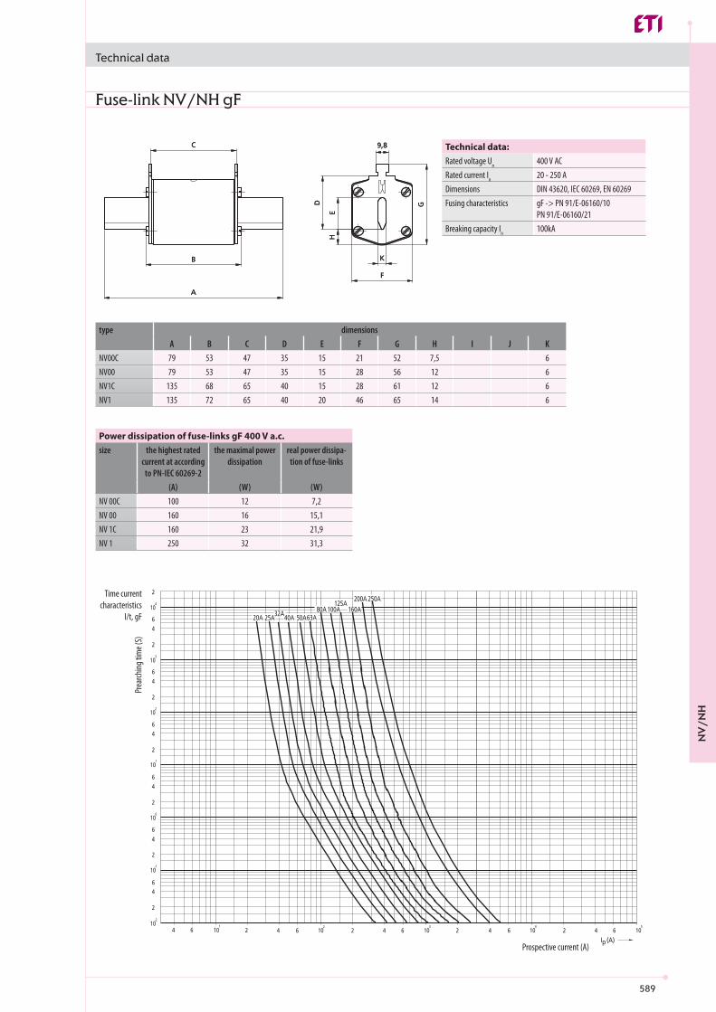
400 V AC20 - 250 A DIN 43620, IEC 60269, EN 60269 gF -> PN 91/E-06160/10 PN 91/E-06160/21100kA
(A) (W) (W)NV 00 C 100 12 7,2NV 00 160 16 15,1NV 1C 160 23 21,9NV 1 250 32 31,3
A B C D E F G H I J KNV00C 79 53 47 35 15 21 52 7,5 6NV00 79 53 47 35 15 28 56 12 6NV1C 135 68 65 40 15 28 61 12 6NV1 135 72 65 40 20 46 65 14 6
Technical data
Prospective current (A)
Prea
rching
tim
e (S)
Fuse-link NV/NH gF
Technical data:Rated voltage Un Rated current In
DimensionsFusing characteristics
Breaking capacity In
Power dissipation of fuse-links gF 400 V a.c.size the highest rated
current at according to PN-IEC 60269-2
the maximal power dissipation
real power dissipa-tion of fuse-links
type dimensions
Time current characteristics
I/t, gF
NV
/NH

590
50 kV
A
75 kV
A
100 k
VA
125 k
VA16
0 kVA
200 k
VA
250 k
VA31
5 kVA
400 k
VA
500 k
VA
630 k
VA80
0 kVA
1000
kVA
Ip (A)
t v (s)400 V AC
50-1000 kVA100 kA
00 1 2 3
Un V a.c. 690In A 160 250 400 630Ith A 160 250 400 630Ith A 200 320 500 800
Hz 40-60Pa W 12 32 45 60Icu kA 200≤ 35 0C 140 0C 0,9550 0C 0,85
Tamb0C -25...+55
3III
IEC 60269-2, DIN VDE 0636, DIN 43620
Technical data
Prea
rching
tim
e (S)
Fuse-link NV/NH gTrTime current
characteristics I/t, gTr
Technical data:Rated voltage Rated transformer powerBreaking capacity
Prospective current (A)
PK Fuse Bases with Ceramic Insulation sizes 00 to 3
Technical data
SizeElectrical characteristicsRated voltageRated currentConv. free air thermal current with fuse linksConv. free air thermal current with solid linksRated frequencyMax. permis. power dissipation per fuse linkMax. breaking capacity per fuse link
Derating temperature factors for max. current
Mechanical characteristicsAmbient temperature rangeRated operating mode uninterruptedMounting position vertical, horizontalPollution degreeOvervoltage categoryDegree of protection IP00 without covers; IP20 with covers fittedStandards
NV
/NH

591
100
5784
60
67
96
25
4,5
120
20
2465
25
31
120
20
1p 3p E F L P R S* T*PK 00 M8-M8 1p S PK 00 M8-M8 3p S M8-M8 Ø 7,5 \ \ \ 88 126PK 00 2M6-2M6 1p S PK 00 2M6-2M6 3p S 2M6-2M6 Ø 7,5 \ \ \ 88 126PK 00 M8-2M6 1p S PK 00 M8-2M6 3p S M8-2M6 Ø 7,5 \ \ \ 88 126PK 00 M8-P00 1p S PK 00 M8-P00 3p S M8-P00 Ø 7,5 \ \ \ 88 126PK 00 M8-2P00 1p S PK 00 M8-2P00 3p S M8-2P00 Ø 7,5 \ \ \ 88 126PK 00 P00-P00 1p S PK 00 P00-P00 3p S P00-P00 Ø 7,5 \ \ \ 88 126PK 00 P00-2P00 1p S PK 00 P00-2P00 3p S P00-2P00 Ø 7,5 \ \ \ 88 126PK 00 2P00-2P00 1p S PK 00 2P00-2P00 3p S 2P00-2P00 Ø 7,5 \ \ \ 88 126
PKI 00 M8-M8 1p S PKI 00 M8-M8 3p S M8-M8 Ø 7,5 87 140 \ \ \PKI 00 2M6-2M6 1p S PKI 00 2M6-2M6 3p S 2M6-2M6 Ø 7,5 87 140 \ \ \PKI 00 M8-2M6 1p S PKI 00 M8-2M6 3p S M8-2M6 Ø 7,5 87 140 \ \ \PKI 00 M8-P00 1p S PKI 00 M8-P00 3p S M8-P00 Ø 7,5 87 140 \ \ \PKI 00 M8-2P00 1p S PKI 00 M8-2P00 3p S M8-2P00 Ø 7,5 87 140 \ \ \PKI 00 P00-P00 1p S PKI 00 P00-P00 3p S P00-P00 Ø 7,5 87 140 \ \ \PKI 00 P00-2P00 1p S PKI 00 P00-2P00 3p S P00-2P00 Ø 7,5 87 140 \ \ \PKI 00 2P00-2P00 1p S PKI 00 2P00-2P00 3p S 2P00-2P00 Ø 7,5 87 140 \ \ \
PKIP 00 M8-M8 1p S PKIP 00 M8-M8 3p S M8-M8 Ø 7,5 87 140 95 \ \PKIP 00 2M6-2M6 1p S PKIP 00 2M6-2M6 3p S 2M6-2M6 Ø 7,5 87 140 95 \ \PKIP 00 M8-2M6 1p S PKIP 00 M8-2M6 3p S M8-2M6 Ø 7,5 87 140 95 \ \PKIP 00 M8-P00 1p S PKIP 00 M8-P00 3p S M8-P00 Ø 7,5 87 140 95 \ \PKIP 00 M8-2P00 1p S PKIP 00 M8-2P00 3p S M8-2P00 Ø 7,5 87 140 95 \ \PKIP 00 P00-P00 1p S PKIP 00 P00-P00 3p S P00-P00 Ø 7,5 87 140 95 \ \PKIP 00 P00-2P00 1p S PKIP 00 P00-2P00 3p S P00-2P00 Ø 7,5 87 140 95 \ \PKIP 00 2P00-2P00 1p S PKIP 00 2P00-2P00 3p S 2P00-2P00 Ø 7,5 87 140 95 \ \
100
5784
60
67
96
25
4,5
120
20
2465
25
31
120
20
Technical data
Dimensions for size 00
*Protective barriers; included with PK 00 3p fuse bases or sold separately
NV
/NH
592
80
30
25
10
35
35
30
25
35
10,5
10,5
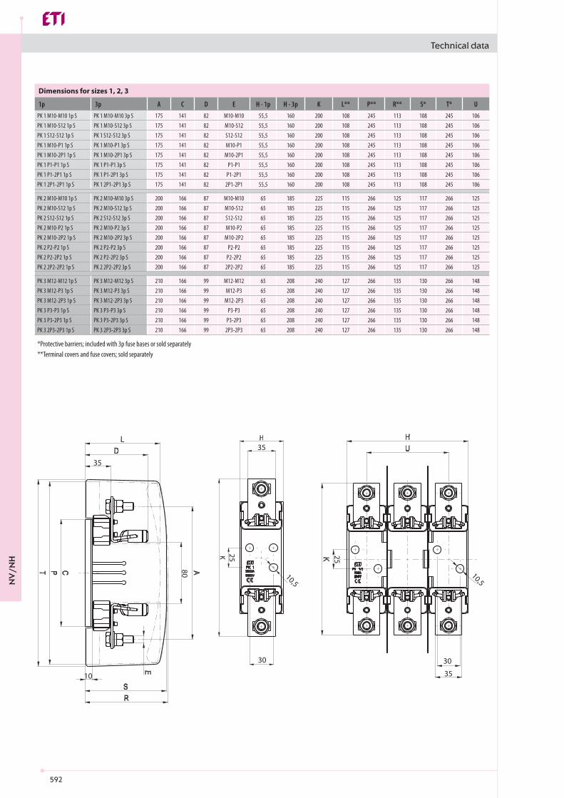
1p 3p A C D E H - 1p H - 3p K L** P** R** S* T* UPK 1 M10-M10 1p S PK 1 M10-M10 3p S 175 141 82 M10-M10 55,5 160 200 108 245 113 108 245 106PK 1 M10-S12 1p S PK 1 M10-S12 3p S 175 141 82 M10-S12 55,5 160 200 108 245 113 108 245 106PK 1 S12-S12 1p S PK 1 S12-S12 3p S 175 141 82 S12-S12 55,5 160 200 108 245 113 108 245 106PK 1 M10-P1 1p S PK 1 M10-P1 3p S 175 141 82 M10-P1 55,5 160 200 108 245 113 108 245 106PK 1 M10-2P1 1p S PK 1 M10-2P1 3p S 175 141 82 M10-2P1 55,5 160 200 108 245 113 108 245 106PK 1 P1-P1 1p S PK 1 P1-P1 3p S 175 141 82 P1-P1 55,5 160 200 108 245 113 108 245 106PK 1 P1-2P1 1p S PK 1 P1-2P1 3p S 175 141 82 P1-2P1 55,5 160 200 108 245 113 108 245 106PK 1 2P1-2P1 1p S PK 1 2P1-2P1 3p S 175 141 82 2P1-2P1 55,5 160 200 108 245 113 108 245 106
PK 2 M10-M10 1p S PK 2 M10-M10 3p S 200 166 87 M10-M10 65 185 225 115 266 125 117 266 125PK 2 M10-S12 1p S PK 2 M10-S12 3p S 200 166 87 M10-S12 65 185 225 115 266 125 117 266 125PK 2 S12-S12 1p S PK 2 S12-S12 3p S 200 166 87 S12-S12 65 185 225 115 266 125 117 266 125PK 2 M10-P2 1p S PK 2 M10-P2 3p S 200 166 87 M10-P2 65 185 225 115 266 125 117 266 125PK 2 M10-2P2 1p S PK 2 M10-2P2 3p S 200 166 87 M10-2P2 65 185 225 115 266 125 117 266 125PK 2 P2-P2 1p S PK 2 P2-P2 3p S 200 166 87 P2-P2 65 185 225 115 266 125 117 266 125PK 2 P2-2P2 1p S PK 2 P2-2P2 3p S 200 166 87 P2-2P2 65 185 225 115 266 125 117 266 125PK 2 2P2-2P2 1p S PK 2 2P2-2P2 3p S 200 166 87 2P2-2P2 65 185 225 115 266 125 117 266 125
PK 3 M12-M12 1p S PK 3 M12-M12 3p S 210 166 99 M12-M12 65 208 240 127 266 135 130 266 148PK 3 M12-P3 1p S PK 3 M12-P3 3p S 210 166 99 M12-P3 65 208 240 127 266 135 130 266 148PK 3 M12-2P3 1p S PK 3 M12-2P3 3p S 210 166 99 M12-2P3 65 208 240 127 266 135 130 266 148PK 3 P3-P3 1p S PK 3 P3-P3 3p S 210 166 99 P3-P3 65 208 240 127 266 135 130 266 148PK 3 P3-2P3 1p S PK 3 P3-2P3 3p S 210 166 99 P3-2P3 65 208 240 127 266 135 130 266 148PK 3 2P3-2P3 1p S PK 3 2P3-2P3 3p S 210 166 99 2P3-2P3 65 208 240 127 266 135 130 266 148
80
30
25
10
35
35
30
25
35
10,5
10,5
Technical data
Dimensions for sizes 1, 2, 3
*Protective barriers; included with 3p fuse bases or sold separately**Terminal covers and fuse covers; sold separately
NV
/NH

593
a b c d emax
POO 24 15 15 M5 25 2,6 10-70 Cu/AI2POO 24 15 15 M5 35 2,6 2x(10-50) Cu/AIP1 37 20 25 M6 30 4,5 70-150 Cu/AI2P1 37 20 25 M6 42 4,5 2x(70-95) Cu/AIP2 42 22 28 M8 40 11 120-240 Cu/AI2P2 42 22 28 M8 55 11 2x(120-150) Cu/AIP3 50 25 30 M8 44 11 120-300 Cu/AI2P3 50 25 30 M8 66 11 2x(120-240) Cu/AI2xM6 26 15 14 M6 16 4 6-70 CuS12 36 16 25 M6 25 9,5 25-150CuM8 M8 20 10MIO M10 30 32M12 M12 30 32
35 23 58 45 22
SM: 50-240 Cu/AI SE: 300 Cu/AI
RM: 37-70 Cu/AI RE: 25-50 Cu/AI
00 1 2 3
Un V a.c. 690In A 160 250 400 630
M8-2M5 M10-M10 M12-M12Nm 10-2,6 32
Technical data
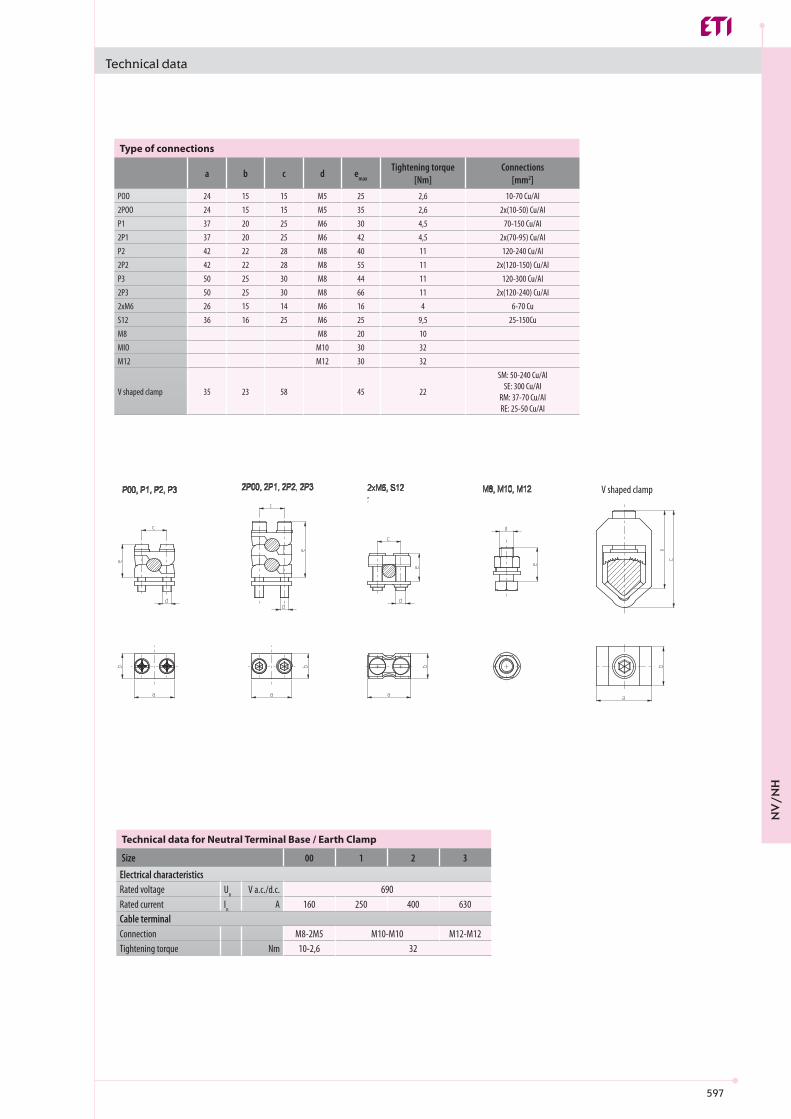
Type of connections
Tightening torque [Nm]
Connections[mm2]
V shaped clamp
Technical data for Neutral Terminal Base / Earth Clamp
SizeElectrical characteristicsRated voltageRated currentCable terminalConnectionTightening torque
V shaped clamp
NV
/NH

594
00 1 2 3
Un V a.c. 690In A 160 250 400 630Ith A 160 250 400 630Ith A 200 320 500 800
Hz 40-60Pa W 12 32 45 60Icu kA 120≤ 35 0C 140 0C 0,9550 0C 0,85
Tamb0C -25...+55
3III
IEC 60269-2, DIN VDE 0636, DIN 43620
[mm] A B C D E F G H I J
PK 00/0 M8-2M5 S 100 84 4,5 26,5 Ø 7,5 25 \ 31 20 115PK 1 M10-M10 S 175 141 10 38 Ø 10,5 25 30 55,5 26 200PK 2 M10-M10 S 200 166 10 40 Ø 10,5 25 30 65 30 225PK 3 M12-M12 S 210 166 10 40 Ø 10,5 25 30 65 30 240
Technical data
Plastic fuse bases type PT size 00 to 3
Technical data
SizeElectrical characteristicsRated voltageRated currentConv. free air thermal current with fuse linksConv. free air thermal current with solid linksRated frequencyMax. permis. power dissipation per fuse linkMax. breaking capacity per fuse link
Derating temperature factors for max. current
Mechanical characteristicsAmbient temperature rangeRated operating mode uninterruptedMounting position vertical, horizontalPollution degreeOvervoltage categoryDegree of protection IP00 without covers; IP20 with covers fittedStandards
Dimensions for Neutral Terminal Base / Earth Clamp
NV
/NH
595
1005785
57
66
37
98
25
16
120
120
20 20
23,566
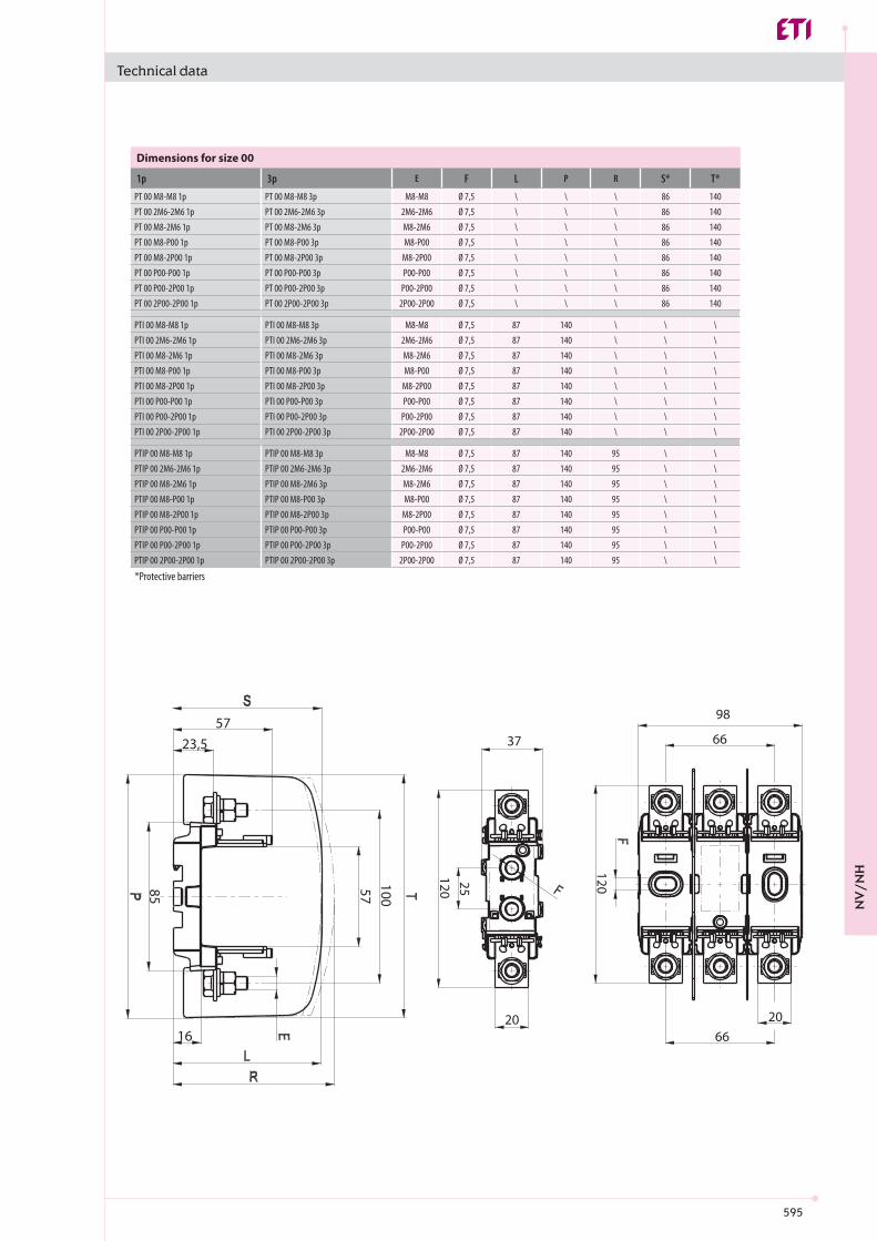
1p 3p E F L P R S* T*PT 00 M8-M8 1p PT 00 M8-M8 3p M8-M8 Ø 7,5 \ \ \ 86 140PT 00 2M6-2M6 1p PT 00 2M6-2M6 3p 2M6-2M6 Ø 7,5 \ \ \ 86 140PT 00 M8-2M6 1p PT 00 M8-2M6 3p M8-2M6 Ø 7,5 \ \ \ 86 140PT 00 M8-P00 1p PT 00 M8-P00 3p M8-P00 Ø 7,5 \ \ \ 86 140PT 00 M8-2P00 1p PT 00 M8-2P00 3p M8-2P00 Ø 7,5 \ \ \ 86 140PT 00 P00-P00 1p PT 00 P00-P00 3p P00-P00 Ø 7,5 \ \ \ 86 140PT 00 P00-2P00 1p PT 00 P00-2P00 3p P00-2P00 Ø 7,5 \ \ \ 86 140PT 00 2P00-2P00 1p PT 00 2P00-2P00 3p 2P00-2P00 Ø 7,5 \ \ \ 86 140
PTI 00 M8-M8 1p PTI 00 M8-M8 3p M8-M8 Ø 7,5 87 140 \ \ \PTI 00 2M6-2M6 1p PTI 00 2M6-2M6 3p 2M6-2M6 Ø 7,5 87 140 \ \ \PTI 00 M8-2M6 1p PTI 00 M8-2M6 3p M8-2M6 Ø 7,5 87 140 \ \ \PTI 00 M8-P00 1p PTI 00 M8-P00 3p M8-P00 Ø 7,5 87 140 \ \ \PTI 00 M8-2P00 1p PTI 00 M8-2P00 3p M8-2P00 Ø 7,5 87 140 \ \ \PTI 00 P00-P00 1p PTI 00 P00-P00 3p P00-P00 Ø 7,5 87 140 \ \ \PTI 00 P00-2P00 1p PTI 00 P00-2P00 3p P00-2P00 Ø 7,5 87 140 \ \ \PTI 00 2P00-2P00 1p PTI 00 2P00-2P00 3p 2P00-2P00 Ø 7,5 87 140 \ \ \
PTIP 00 M8-M8 1p PTIP 00 M8-M8 3p M8-M8 Ø 7,5 87 140 95 \ \PTIP 00 2M6-2M6 1p PTIP 00 2M6-2M6 3p 2M6-2M6 Ø 7,5 87 140 95 \ \PTIP 00 M8-2M6 1p PTIP 00 M8-2M6 3p M8-2M6 Ø 7,5 87 140 95 \ \PTIP 00 M8-P00 1p PTIP 00 M8-P00 3p M8-P00 Ø 7,5 87 140 95 \ \PTIP 00 M8-2P00 1p PTIP 00 M8-2P00 3p M8-2P00 Ø 7,5 87 140 95 \ \PTIP 00 P00-P00 1p PTIP 00 P00-P00 3p P00-P00 Ø 7,5 87 140 95 \ \PTIP 00 P00-2P00 1p PTIP 00 P00-2P00 3p P00-2P00 Ø 7,5 87 140 95 \ \PTIP 00 2P00-2P00 1p PTIP 00 2P00-2P00 3p 2P00-2P00 Ø 7,5 87 140 95 \ \
1005785
57
66
37
98
25
16120
120
20 20
23,566
Technical data
Dimensions for size 00
*Protective barriers
NV
/NH
596
80
156
3030
60
25 25
3535
34
80
156
3030
60
25 25
3535
34
1p 3p A D E F H J K L** P** R** S* T* UPT 1 M10-M10 1p PT 1 M10-M10 3p 175 81 M10-M10 10,5 190 25 200 103 244 110 108 241 130PT 1 M10-S12 1p PT 1 M10-S12 3p 175 81 M10-S12 10,5 190 25 200 103 244 110 108 241 130PT 1 S12-S12 1p PT 1 S12-S12 3p 175 81 S12-S12 10,5 190 25 200 103 244 110 108 241 130PT 1 M10-P1 1p PT 1 M10-P1 3p 175 81 M10-P1 10,5 190 25 200 103 244 110 108 241 130PT 1 M10-2P1 1p PT 1 M10-2P1 3p 175 81 M10-2P1 10,5 190 25 200 103 244 110 108 241 130PT 1 P1-P1 1p PT 1 P1-P1 3p 175 81 P1-P1 10,5 190 25 200 103 244 110 108 241 130PT 1 P1-2P1 1p PT 1 P1-2P1 3p 175 81 P1-2P1 10,5 190 25 200 103 244 110 108 241 130PT 1 2P1-2P1 1p PT 1 2P1-2P1 3p 175 81 2P1-2P1 10,5 190 25 200 103 244 110 108 241 130
PT 2 M10-M10 1p PT 2 M10-M10 3p 200 87 M10-M10 10,5 190 25 225 112 268 120 115,5 266 130PT 2 M10-S12 1p PT 2 M10-S12 3p 200 87 M10-S12 10,5 190 25 225 112 268 120 115,5 266 130PT 2 S12-S12 1p PT 2 S12-S12 3p 200 87 S12-S12 10,5 190 25 225 112 268 120 115,5 266 130PT 2 M10-P2 1p PT 2 M10-P2 3p 200 87 M10-P2 10,5 190 25 225 112 268 120 115,5 266 130PT 2 M10-2P2 1p PT 2 M10-2P2 3p 200 87 M10-2P2 10,5 190 25 225 112 268 120 115,5 266 130PT 2 P2-P2 1p PT 2 P2-P2 3p 200 87 P2-P2 10,5 190 25 225 112 268 120 115,5 266 130PT 2 P2-2P2 1p PT 2 P2-2P2 3p 200 87 P2-2P2 10,5 190 25 225 112 268 120 115,5 266 130PT 2 2P2-2P2 1p PT 2 2P2-2P2 3p 200 87 2P2-2P2 10,5 190 25 225 112 268 120 115,5 266 130
PT 3 M12-M12 1p PT 3 M12-M12 3p 210 98 M12-M12 10,5 222 10 240 126 268 133 130 267 166PT 3 M12-P3 1p PT 3 M12-P3 3p 210 98 M12-P3 10,5 222 10 240 126 268 133 130 267 166PT 3 M12-2P3 1p PT 3 M12-2P3 3p 210 98 M12-2P3 10,5 222 10 240 126 268 133 130 267 166PT 3 P3-P3 1p PT 3 P3-P3 3p 210 98 P3-P3 10,5 222 10 240 126 268 133 130 267 166PT 3 P3-2P3 1p PT 3 P3-2P3 3p 210 98 P3-2P3 10,5 222 10 240 126 268 133 130 267 166PT 3 2P3-2P3 1p PT 3 2P3-2P3 3p 210 98 2P3-2P3 10,5 222 10 240 126 268 133 130 267 166
Technical data
Dimensions for sizes 1, 2, 3
*Protective barriers; included with 3p fuse bases or sold separately**Terminal covers and fuse covers; sold separately
NV
/NH
597
a b c d emax
POO 24 15 15 M5 25 2,6 10-70 Cu/AI2POO 24 15 15 M5 35 2,6 2x(10-50) Cu/AIP1 37 20 25 M6 30 4,5 70-150 Cu/AI2P1 37 20 25 M6 42 4,5 2x(70-95) Cu/AIP2 42 22 28 M8 40 11 120-240 Cu/AI2P2 42 22 28 M8 55 11 2x(120-150) Cu/AIP3 50 25 30 M8 44 11 120-300 Cu/AI2P3 50 25 30 M8 66 11 2x(120-240) Cu/AI2xM6 26 15 14 M6 16 4 6-70 CuS12 36 16 25 M6 25 9,5 25-150CuM8 M8 20 10MIO M10 30 32M12 M12 30 32
35 23 58 45 22
SM: 50-240 Cu/AI SE: 300 Cu/AI
RM: 37-70 Cu/AI RE: 25-50 Cu/AI
00 1 2 3
Un V a.c./d.c. 690In A 160 250 400 630
M8-2M5 M10-M10 M12-M12Nm 10-2,6 32
Technical data
V shaped clamp
Technical data for Neutral Terminal Base / Earth Clamp
SizeElectrical characteristicsRated voltageRated currentCable terminalConnectionTightening torque
Type of connections
Tightening torque [Nm]
Connections[mm2]
V shaped clamp
NV
/NH

598
M 8
134
8710
4
343414 7,
568*
25*
M 8
14
232
134
5932
533620
120
86,5
25*
7,5*
*
PLNV - 00/1 PLNV - 00/3
A
EE
H
10
10,5
J
I
BG
35
C25
FD
30
48
*
*
*
BA
30
55 48H
10
10,5
DG
35
C25
J
*
*
*
2PLNV - 1,2,3/1 2PLNV - 1,2,3/3
2343
12680
A
7,5 14
30
146
25 *
*
APLNVV -000
PLNVV -00M8
M10
PLNVV - 00C, 00
690 V AC
3 -> IEC 60947, DIN EN 60947, DIN VDE 0110 IEC 60269, DIN EN 60269, DIN VDE 0636, HRN EN 60269
[mm] A B C D E F G H I J
PT 00/0 M8-2M5 S 100 85 4,5 26,5 Ø 7,5 25 \ 37 20 115PT 1 M10-M10 S 175 156 10 38 Ø 10,5 25 30 60 26 200PT 2 M10-M10 S 200 156 10 40 Ø 10,5 25 30 60 30 225PT 3 M12-M12 S 210 156 10 40 Ø 10,5 25 30 60 30 240
Technical data
Dimensions
Technical data:Rated voltage Un Rated current In 160 A - sizes 00C, 00, 0
250 A - size 1400 A - size 2630 A - size 3
Degree of pollutionStandards
Plastic fuse bases type PLNVV 000 and 00 (fuses with screw connection - S)
Dimensions for Neutral Terminal Base / Earth Clamp
NV
/NH

599
a
20
15
15
16
15
20
22
22
52
52
M6
M5
M5
6M
M5
M6
M8
M8
M8
M8
42
40
44
66
30
55
25
52
15
35
25
15
15
25
15
25
82
82
30
30
37
24
24
36
24
37
42
42
50
50
OS00
OS12
P00
P002
P1
P22
P12
P2
P3
P32
b c d emax
a
b
c
d
e
a
b
c
d
e
a
b
c
d
e
OS 00, OS 12 P00, P1, P2, P3 P002, P12, P22, P32
max
58
max
45
22
25
35
5530
10,5
D
M10
CB
60
*
*
*
100
43
23
M4
120
25
7 . 5
1 46
M82
0*
*
2PLNS - 1N175,6
20025
2PLNS - 2N200230
30
BCD
PLNS - 00 N 2PLNS - 1,2 N
Technical data
Neutral terminal base PLNS
Technical data
Type a b c d emax
“V” shaped clamp
NV
/NH
600
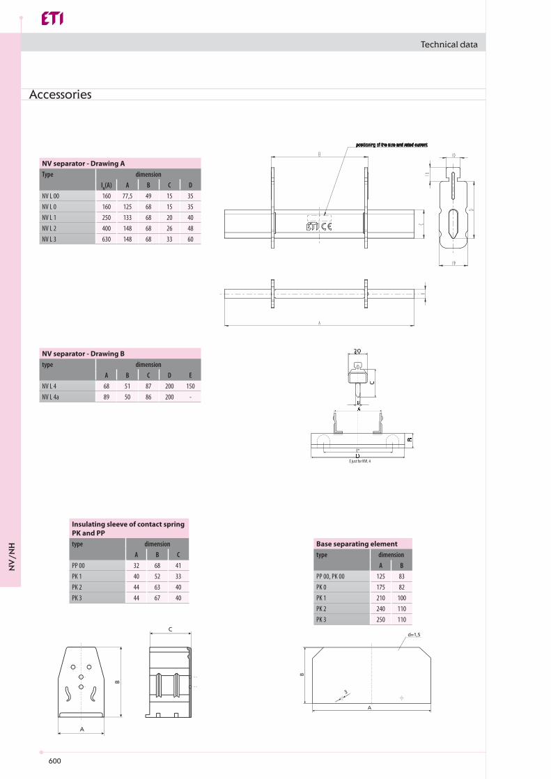
A B CPP 00 32 68 41PK 1 40 52 33PK 2 44 63 40PK 3 44 67 40
A BPP 00, PK 00 125 83PK 0 175 82PK 1 210 100PK 2 240 110PK 3 250 110
A B C D ENV L 4 68 51 87 200 150NV L 4a 89 50 86 200 -
3
A
B
d =1,5
A
C
B
20
E*
E just for NVL 4
IN(A) A B C DNV L 00 160 77,5 49 15 35NV L 0 160 125 68 15 35NV L 1 250 133 68 20 40NV L 2 400 148 68 26 48NV L 3 630 148 68 33 60
Technical data
Accessories
Insulating sleeve of contact spring PK and PPtype dimension Base separating element
type dimension
NV separator - Drawing Btype dimension
NV separator - Drawing AType dimension
NV
/NH

601
VL00/100 VL00/185 VL1 VL1H
Ue V 690 AC 690 AC 690 AC 690 ACIe A 160 160 250 250- Hz 40-60 40-60 40-60 40-60Ui V 800 AC 1000 ACPv W 18 23 23 29
- - 000/00 1In A 160 160 250 250Pv W 12 32 23
- kg 100 mm = 0,8 185mm=1,5 3,5- mm 100 185 185
- - M8 M10Ma Nm 12-15 30-35
- mm2 10-95 25-300 25-240 / 25-300Ma Nm 10 32
- - IP10
TuOC -25 ... +55
- -- -- m ≤ 2000- - 3- - III IV
VL2 VL2H VL3
Ue V 690 AC 690 AC 690 ACIe A 400 400 630- Hz 40-60 40-60 40-60Ui V 1000 ACPv W 54 73 115
- - 2 3In A 400 400 630Pv W 45 34 48
- kg 3,8 4,3- mm 185
- - M12 M12 M12Ma Nm 35-40 35-40 35-40
- mm2 25-300 25-240 / 25-300 25-300Ma Nm 32 32 32
- - IP10
TuOC -25 ... +55
- -- -- m ≤ 2000- - 3- - IV
Technical data
NV fuse-rail sizes 00, 1, 2, 3
Technical data of insulated fuse-rails (in accordance with VDE 0636, part 201, IEC 60269-2-1)Technical SpecificationsElectrical CharacteristicsRated operational voltageRated operational currentRated frequencyRated insulation voltageTotal power loss at Ith (without fuse)Fuse linksSize - DIN 43 620, IEC 60269-2Max. rated current (gG)Max. permissible power loss per fuse link Dimensions MassBusbars (distance)Cable connectionScrewTorqueV-clipTorqueProtectionOperational stateOperating conditionsAmbient temperatureOperating condition - - Continuous operationMounting - - vertical, horizontalAltitude -Pollution degree - -Overvoltage category - -
Technical data of insulated fuse-rails (in accordance with VDE 0636, part 201, IEC 60269-2-1)Technical SpecificationsElectrical CharacteristicsRated operational voltageRated operational currentRated frequencyRated insulation voltageTotal power loss at Ith (without fuse)Fuse linksSize - DIN 43 620, IEC 60269-2Max. rated current (gG)Max. permissible power loss per fuse link Dimensions MassBusbars (distance)Cable connectionScrewTorqueV-clipTorqueProtectionOperational stateOperating conditionsAmbient temperatureOperating condition - - Continuous operationMounting - - vertical, horizontalAltitude -Pollution degree - -Overvoltage category - -
NV
/NH

602
Technical data
size 1, 2, 3 (M terminal)
Dimensional overview of LV NV fuse-rails
size 00/185size 00/100
NV
/NH
603
Technical data
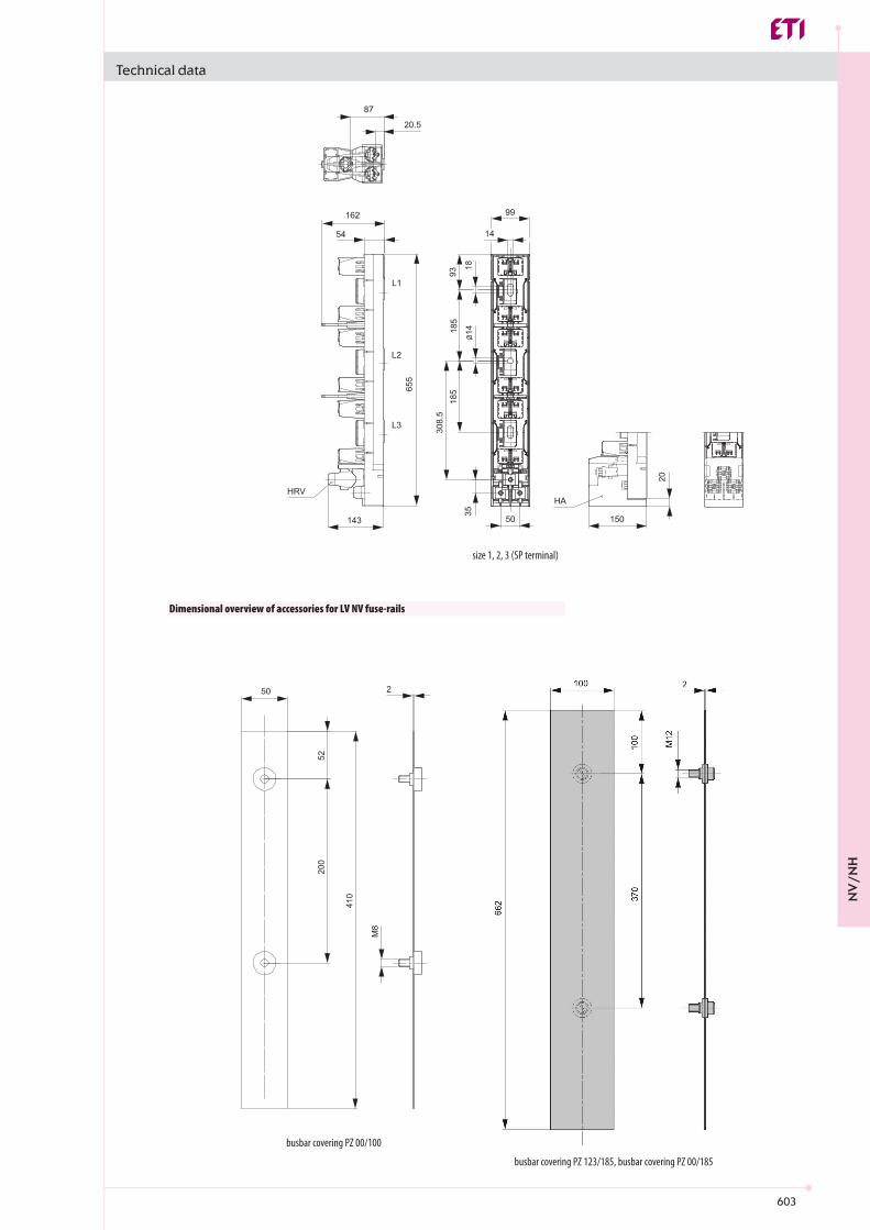
busbar covering PZ 123/185, busbar covering PZ 00/185
busbar covering PZ 00/100
size 1, 2, 3 (SP terminal)
Dimensional overview of accessories for LV NV fuse-rails
NV
/NH
604
9O
9x16
40
9
10
01
00
16
0
49
9O
9x16
40
9
10
01
00
16
0
49
18
36
,53
3
7 ,36,3
8,8
8,8
83
1743
69111
Technical data
Type VL00/100 EK
Conventional free air thermal current (Ith) A 160Rated insulation voltage V AC690Rated withstand impulse voltage Kv 6Rated frequency Hz 50 (40-60)Power dissipation (without fuse-links) W 16,6Degree of protection ( cover closed ) IP20Degree of protection ( cover opened ) IP20Pollution degree 3Permissible ambient temperature** °C -25°C ... +55°CStorage temperature °C -30°C ... +70°CWeight ( without fuse-links ) kg 0,86Package pcs 1
Technical data
busbar support PP 100/185
busbar covering PZ 00/185
NV fuse-rail type VL00 EK
Technical data
Type VL00/100 EK
Conventional free air thermal current (Ith) A 160Rated insulation voltage V AC690Rated withstand impulse voltage Kv 6Rated frequency Hz 50 (40-60)Power dissipation (without fuse-links) W 16,6Degree of protection ( cover closed ) IP20Degree of protection ( cover opened ) IP20Pollution degree 3Permissible ambient temperature** °C -25°C ... +55°CStorage temperature °C -30°C ... +70°CWeight ( without fuse-links ) kg 0,86Package pcs 1** with ambient temperature between 40-45°C, reduce Ith by 5%; with ambient temperature above 45°C, reduce Ith by 10%
NV
/NH

605
SL00/100 SL00/185 SL1
Ue V 500 AC 690 AC 400 AC 500 AC 690 AC 400 AC 500 AC 690 AC 400 ACIe A 160 100 160 160 160 160 250 250 250- Hz 40-60 40-60 40-60 40-60 40-60 40-60 40-60 40-60 40-60Ui V AC 800 AC 1000Pv W 18 23- - AC22B AC22B AC22B AC23B AC22B AC23B AC22B AC22B AC23B
- - 000/00 1In A 160 100 160 160 160 160 250 250 250Pv W 12 32
- kg 100 mm = 1,40 185mm=2,4 4,9- mm 100 185 185
- - M8 M10Ma Nm 12-15 30-35
- mm2 10-95 25-300Ma Nm 15 32
- - IP30 IP30- - IP10 IP10
TuOC -25 ... +55 -25 ... +55
- -- -- m ≤ 2000- - 3- - III IV
3 x M8M=12Nm
100
mm
100
mm
6 x M8M=12Nm
185
mm
185
mm
Pribor / Accessories
Pribor / Accessories
Pribor / Accessories
Technical data
NV Strip type fuse-switch-disconnector sizes 00, 1, 2, 3
Technical data of NV strip type fuse-switch-disconnectors (in accordance with IEC/EN 60947-3)Technical SpecificationsElectrical CharacteristicsRated operational voltageRated operational currentRated frequencyRated insulation voltageTotal power loss at Ith (without fuse)Utilization categoryFuse linksSize - DIN 43 620, IEC 60269-2Max. rated current (gG)Max. permissible power loss per fuse link DimensionsMassBusbars (distance)Cable connectionScrewTorqueV-clipTorqueProtectionOperational stateCover openOperating conditionsAmbient temperatureOperating condition Continuous operationMounting vertical, horizontalAltitudePollution degreeOvervoltage category
NV
/NH

606
SL1H SL2
Ue V 500 AC 690 AC 400 AC 500 AC 690 AC 400 ACIe A 250 400 400 400- Hz 40-60 40-60 40-60 40-60Ui V AC 1000 Pv W 29 54- - AC22B AC21B AC23B AC22B AC21B AC23B
- - 1 2In A 250 400 400 400Pv W 23 45
- kg 4,9- mm 185
- - M10 M12Ma Nm 30-35 35-40
- mm2 25-240 / 25-300 25-300Ma Nm 32
- - IP30- - IP10
TuOC -25 ... +55
- -- -- m ≤ 2000- - 3- - IV
SL2H SL3
Ue V 500 AC 690 AC 400 AC 500 AC 690 AC 400 ACIe A 400 630 630 630- Hz 40-60 40-60 40-60 40-60Ui V AC 1000 Pv W 73 115- - AC22B AC21B AC23B AC22B AC21B AC23B
- - 2 3In A 400 630 630 630Pv W 34 48
- kg 4,9 5,6- mm 185
- - M12 M12Ma Nm 35-40 35-40
- mm2 25-240 / 25-300 25-300Ma Nm 32
- - IP30- - IP10
TuOC -25 ... +55
- -- -- m ≤ 2000- - 3- - IV
Technical data
Technical data of NV strip type fuse-switch-disconnectors (in accordance with IEC/EN 60947-3)Technical SpecificationsElectrical CharacteristicsRated operational voltageRated operational currentRated frequencyRated insulation voltageTotal power loss at Ith (without fuse)Utilization categoryFuse linksSize - DIN 43 620, IEC 60269-2Max. rated current (gG)Max. permissible power loss per fuse link Dimensions MassBusbars (distance)Cable connectionScrewTorqueV-clipTorqueProtectionOperational stateFront cover openOperating conditionsAmbient temperatureOperating condition Continuous operationMounting vertical, horizontalAltitudePollution degreeOvervoltage category
Technical data of NV strip type fuse-switch-disconnectors (in accordance with IEC/EN 60947-3)Technical SpecificationsElectrical CharacteristicsRated operational voltageRated operational currentRated frequencyRated insulation voltageTotal power loss at Ith (without fuse)Utilization categoryFuse linksSize - DIN 43 620, IEC 60269-2Max. rated current (gG)Max. permissible power loss per fuse link Dimensions MassBusbars (distance)Cable connectionScrewTorqueV-clipTorqueProtectionOperational stateFront cover openOperating conditionsAmbient temperatureOperating condition Continuous operationMounting vertical, horizontalAltitudePollution degreeOvervoltage category
NV
/NH

607
SL00/185
49
Ø9
64
7
01458 02
061
45
001001
9x16
1945
73120
17
248122
88
003
051051
011
SL00/100
Technical data
Dimensional overview of NV strip type fuse-switch-disconnectors
NV
/NH

608
202153.5
7
L1
14
18
662
056
285
185
L2
1418
5143L3
40
99
100
762
341
185
277.
5
L3
99.5
5226
40
L1
100
185
L2
194SL1(H), SL2(H), SL3
SL3 DOUBLE
44.5 44.523
M12x35L3L2L1
100199
17051
48
4040
814.5
L1
405
883
185
L2
L3
185
277.
599
.5
153.5206
214153.57
L1
14
L2
1418
285
185
185
405
8
L3
14.5
4040
4851170
L3
L2L1
12
2
650662
L3
L2L1 22
1
Technical data
NV
/NH

609
99581
L2
SW19
L1
L3
581
0545.028
M
21M
42
23.5 SW19
5810015,02
0018
M
12M
581
9923,5
L1
L2
52
L3
054
Technical data
Type SL00/100 EK
Conventional free air thermal current (Ith) A 160Rated insulation voltage V AC690Rated withstand impulse voltage Kv 6Rated frequency Hz 50 (40-60)Rated operational ( making and breaking ) voltage V 400V 500V 690 VUtilization category/Rated operational ( making and breaking ) current AC21-B 160A 160A 125AUtilization category/Rated operational ( making and breaking ) current AC22-B 160A 160A 100ARated conditional short-circuit current kAeff 63Mechanical durability ( operating cycles ) 1400Electrical durability ( operating cycles ) 200Power dissipation (without fuse-links) W 19,5Degree of protection ( cover closed ) IP30Degree of protection ( cover opened ) IP20Pollution degree 3Permissible ambient temperature** °C -25°C ... +55°CStorage temperature °C -30°C ... +70°CWeight ( without fuse-links ) kg 1,2Package pcs 1
Technical data
Dimensional overview of accessories for NV strip type fuse-switch-disconnectors
adapter DA 185-185/42 adapter DA 185-100/52
Strip type fuse-switch disconnectors type SL00 EK
Technical data
Type SL00/100 EK
Conventional free air thermal current (Ith) A 160Rated insulation voltage V AC690Rated withstand impulse voltage Kv 6Rated frequency Hz 50 (40-60)Rated operational ( making and breaking ) voltage V 400V 500V 690 VUtilization category/Rated operational ( making and breaking ) current AC21-B 160A 160A 125AUtilization category/Rated operational ( making and breaking ) current AC22-B 160A 160A 100ARated conditional short-circuit current kAeff 63Mechanical durability ( operating cycles ) 1400Electrical durability ( operating cycles ) 200Power dissipation (without fuse-links) W 19,5Degree of protection ( cover closed ) IP30Degree of protection ( cover opened ) IP20Pollution degree 3Permissible ambient temperature** °C -25°C ... +55°CStorage temperature °C -30°C ... +70°CWeight ( without fuse-links ) kg 1,2Package pcs 1** with ambient temperature between 40-45°C, reduce Ith by 5%; with ambient temperature above 45°C, reduce Ith by 10%
NV
/NH
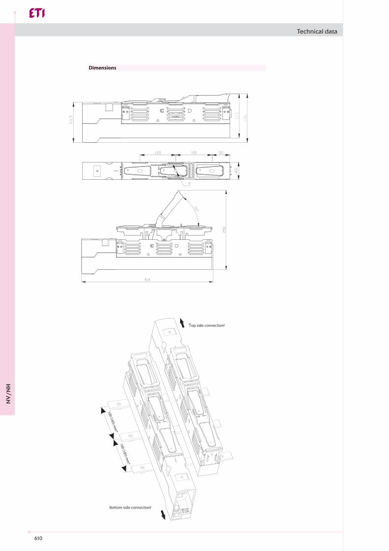
610
100 (185) mm
*100 (185) m
m*
Top side connection!
Bottom side connection!
Technical data
Dimensions
NV
/NH

611
00 1
Ue V 400 AC 500 AC 690 AC 250 DC 440 DC 400 AC 500 AC 690 AC 250 DC 440 DCIe A 160 160 160 160 160 250 250 250 250 250Ith A 160 250Ith A 210 325f Hz 40-60 40-60 40-60 / / 40-60 40-60 40-60 / /
Ui V 800 AC 800 ACPv W 1P - 3W, 3P - 9W 1P - 5W, 3P - 15WPv W 1P - 1,9 W, 3P - 5,8 W 1P - 3,2 W, 3P - 9,6 W
Uimp kV 8 8AC-23B AC-22B AC-21B DC-22B DC-21B AC-23B AC-22B AC-21B DC-22B DC-21B
kA 120 (500V), 100 (690V) 120 (500V), 100 (690V)Icw kA 5/1s 8,6/1s
- - 000/00 1In A 160 160 160 160 160 250 250 250 250 250Pa W 12 23
M8 M10Ma Nm 12-15 30-35
mm2 Round conductor: 1,5-70 Cu , Strip conductor: 6 x 9 x 0,8 Cu
Round conductor: 2,5-150 Cu , Strip conductor: 6 x 16 x 0,8 Cu
Ma Nm 2,6 9,5mm2 (SP KVL00 P1); 10-70 Al/Cu , 35-95 Al/Cu (SP KVL1 P1); 10-150 Al/Cu
Ma Nm (SP KVL00 P1); 2,6 (SP KVL1 P1); 4,5mm2 (SP KVL1 P2); 2 x (10-150) Al/Cu
Ma Nm (SP KVL1 P2); 4,5mm2 1,5-95 Al/Cu , (Al 95: max. 125A), ****** 35-150 Al/Cu
Ma Nm 4,5 12
- - IP20 IP20- - IP10 IP10- - IP2XC IP2XC
TambOC -25 ... +55 -25 ... +55
- -- -- m ≤ 2000- - 3- - III III
Technical data
Horizontal fuse-switch disconnector type KVL size 00, 1, 2, 3 (baseplate mounting)
Technical data (in accordance with IEC/EN 60947-3)SizeTechnical CharacteristicsRated operational voltageRated operational current*Conv. free air thermal current with fuse-links*Conv. free air thermal current with solid-links*Rated frequencyRated insulation voltageTotal power loss (without fuse) Power loss at 80% Ith (without fuse-links), **Rated impulse withstand voltageUtilisation category***Rated conditional short-circuit current, ***, ****Rated short-time withstand currentFuse linksSize - DIN VDE 0636-2Max. rated current (gG)Max. permissible power loss per fuse linkCable terminalFlat terminal-ScrewTightening torqueClip terminal, Clamping cross-section
Tightening torquePrism Clamp, Clamping cross-sectionTightening torquePrism Clamp, Clamping cross-sectionTightening torqueFrame clamp, Clamping cross-sectionTorqueDegree of Protection, front side deviceFront cover closeFront cover open With clamp- and lateral coverOperating conditionAmbient temperature *****Operating condition Continuous operationMounting vertical, horizontalAltitudePollution degreeOvervoltage category
* Mounting of several units in low voltage switchgear-combinations, please think about rated diversity factors acc. to DIN EN 61439. ** Reference value for replacement of devices acc. to DIN EN 61439-1 clause 10.10.4.2.*** minimum distance to earthed, conductive parts: Lateral: 20mm/Above: 50mm *** a) Lateral: 50mm/Above: 100mm**** Type tested with NH fuse-links characteristic gG***** 35°C Normal temperature, at 55°C with reduced operating current
NV
/NH
612
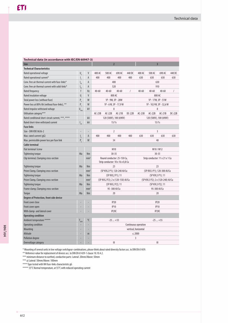
2 3
Ue V 400 AC 500 AC 690 AC 440 DC 400 AC 500 AC 690 AC 440 DCIe A 400 400 400 400 630 630 630 630Ith A 400 630Ith A 520 910f Hz 40-60 40-60 40-60 / 40-60 40-60 40-60 /
Ui V 800 AC 800 ACPv W 1P - 9W, 3P - 28W 1P - 17W, 3P - 51WPv W 1P - 6 W, 3P - 17,9 W 1P - 10,9 W, 3P - 32,6 W
Uimp kV 8 8AC-23B AC-22B AC-21B DC-22B AC-23B AC-22B AC-21B DC-22B
kA 120 (500V), 100 (690V) 120 (500V), 100 (690V)Icw kA 15/1s 15/1s
- - 2 3In A 400 400 400 400 630 630 630 630Pa W 34 48
M10 M10 / M12Ma Nm 30-35 30-35
mm2 Round conductor: 25-150 Cu, Strip conductor: 10 x 16 x 0,8 Cu
Strip conductor: 11 x 21 x 1 Cu
Ma Nm 23 23mm2 (SP KVL2 P1); 120-240 Al/Cu (SP KVL3 P1); 120-300 Al/Cu
Ma Nm (SP KVL2 P1); 11 (SP KVL3 P1); 11mm2 (SP KVL2 P2); 2 x (120-150) Al/Cu (SP KVL3 P2); 2 x (120-240) Al/Cu
Ma Nm (SP KVL2 P2); 11 (SP KVL3 P2); 11mm2 95 -300 Al/Cu 95-300 Al/Cu
Ma Nm 20 20
- - IP20 IP20- - IP10 IP10- - IP2XC IP2XC
TambOC -25 ... +55 -25 ... +55
- -- -- m ≤ 2000- - 3- - III III
Technical data
Technical data (in accordance with IEC/EN 60947-3)SizeTechnical CharacteristicsRated operational voltageRated operational current*Conv. free air thermal current with fuse-links*Conv. free air thermal current with solid-links*Rated frequencyRated insulation voltageTotal power loss (without fuse) Power loss at 80% Ith (without fuse-links), **Rated impulse withstand voltageUtilisation category***Rated conditional short-circuit current, ***, ****Rated short-time withstand currentFuse linksSize - DIN VDE 0636-2Max. rated current (gG)Max. permissible power loss per fuse linkCable terminalFlat terminal-ScrewTightening torqueClip terminal, Clamping cross-section
Tightening torquePrism Clamp, Clamping cross-sectionTightening torquePrism Clamp, Clamping cross-sectionTightening torqueFrame clamp, Clamping cross-sectionTorqueDegree of Protection, front side deviceFront cover closeFront cover open With clamp- and lateral coverOperating conditionAmbient temperature *****Operating condition Continuous operationMounting vertical, horizontalAltitudePollution degreeOvervoltage category
* Mounting of several units in low voltage switchgear-combinations, please think about rated diversity factors acc. to DIN EN 61439. ** Reference value for replacement of devices acc. to DIN EN 61439-1 clause 10.10.4.2.*** minimum distance to earthed, conductive parts: Lateral: 20mm/Above: 50mm *** a) Lateral: 50mm/Above: 100mm**** Type tested with NH fuse-links characteristic gG***** 35°C Normal temperature, at 55°C with reduced operating current
NV
/NH
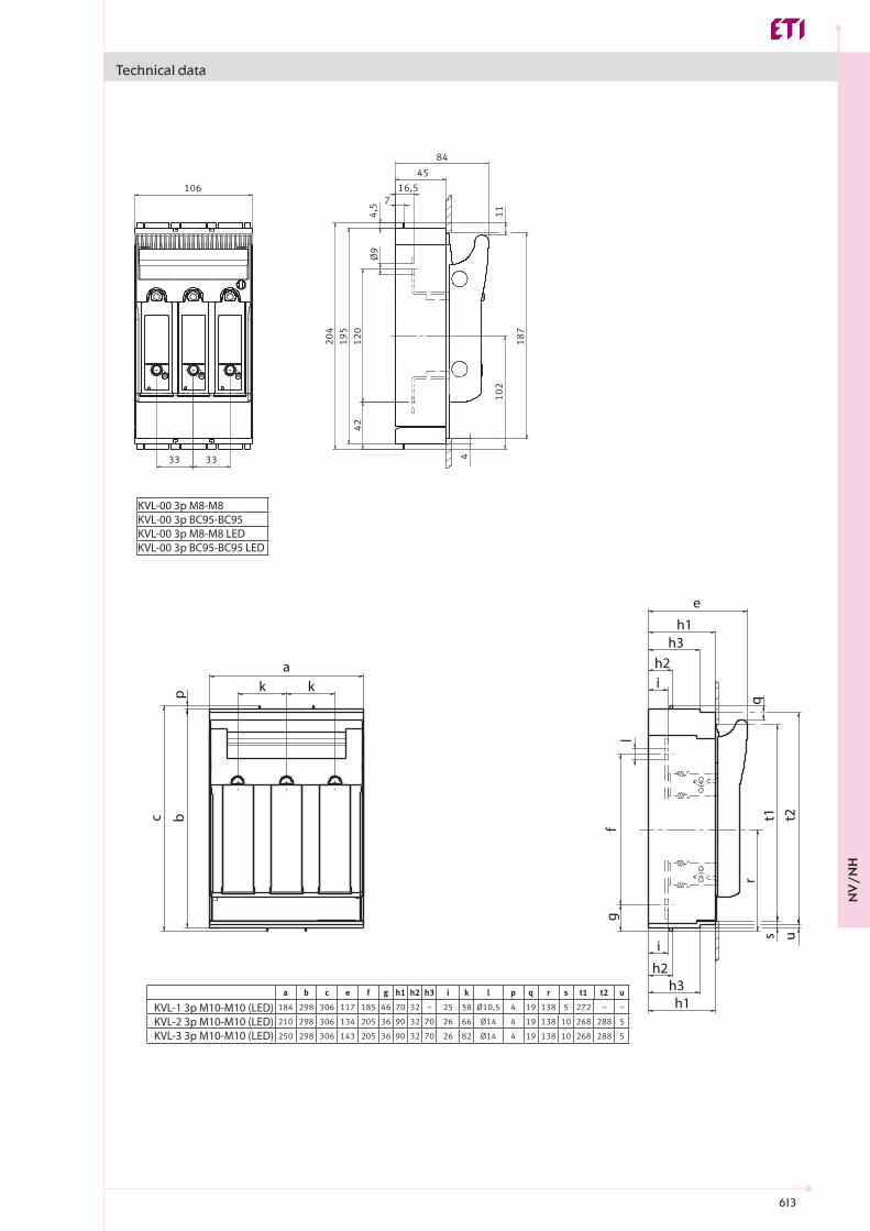
613
KVL-1 3p M10-M10 (LED)KVL-2 3p M10-M10 (LED)KVL-3 3p M10-M10 (LED)
a
pb
fl
q
g
t1 t2s
i
h2h3h1
r
u
c
h1
e
h3h2ik k
KVL-00 3p M8-M8KVL-00 3p BC95-BC95KVL-00 3p M8-M8 LEDKVL-00 3p BC95-BC95 LED
Technical data
NV
/NH

614
a
p
c b
e
i
q
lf
g
i
s
r
a
pbc
e
i
qs
lf
g
r
i
KVL-00 1p KVL-00 2p
KVL-00 1p M8-M8KVL-00 2p M8-M8
KVL-1 1p M10-M10KVL-3 1p M10-M10
a
pbc
fg
l
e
i
i
q
s u
r
Technical data
NV
/NH

615
KVL-1 2p M10-M10KVL-3 2p M10-M10
pbc
a
e
i
q
lf
g
rs ui
a
pbc
lf
g
i
eq
r
s
i
KVL-00 4p M8-M8
Technical data
NV
/NH
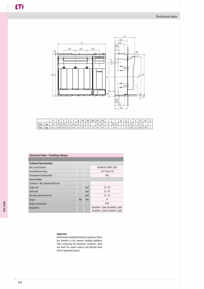
616
l
c bp
a
fg
i
e
qr
s ui
KVL-1 4p KVL-3 4p
AC690V/DC1000V-250A125°C UL94: V0
600
mm² 25 - 95mm² 25 - 95mm² 25 - 70
Ma Nm 13IP20
EN 60998-1:2004; EN 60998-2:2004; EN 60999-1:2000; EN 60999-2:2003
Technical data
Technical data - Feeding clamps
Technical CharacteristicsMax. electrical loadHeat deflection temp.Comparative tracking indexCross sectionsConductor - Max. Diameter Ø14 mmsingle wiremulti wirefine wire (with end sleeve)
TorqueDegree of protectionRegulations
ImportantThis Terminal is suitable for Al and Cu conductors. Please pay attention to the common handling guidelines when connecting the Aluminium conductors. Clean and brush the contact surfaces and lubricate them with an appropriate grease.
NV
/NH

617
PRS KVL-00 3p SPRS KVL-00 3p L
PRS KVL-1 3pPRS KVL-2 3pPRS KVL-3 3p
e
d a
f
c cg
b
c
a b c d e f g
f
PRS KVL-00 1p L
PRS KVL-00 1p S
Technical data
NV
/NH

618
Ue V AC400-500 (+/-10%)
VA 1,5230/400 V : III , (4kV)
500 V : II , (4kV)f Hz 50-60
>1k Ohm/V
1NC/1NOV AC250/DC24A 1
IEC 61000-4-5/IEC 61000-4-4IP 3X
TambOC -5 ... +55
PRS KVL-1 1p
PRS KVL-3 1p
Technical data
Technical data - Electronic fuse monitoring unit EFMU KVL
Technical CharacteristicsRated operational voltagePower supply Self-poweredInput powerOvervoltage category
Rated frequencyInput resistanceOutput channelsRelay outputMaximum voltageMaximum switching currentGeneral dataOperation indicator 1 LED green
Alarm indicator 3 LED (F1, F2, F3) redFunctional test Test key for relay + LEDsEMCDegree of protectionOperating conditionsAmbient temperature
No single detection of parallel connected fuses!
NV
/NH

619
KVL-00 3p M8-M8 + EFMU KVL-00 3pKVL-00 3p BC95-BC95 + EFMU KVL-00 3p
d
q
lf
g
u
r
s
e
i
i
c bp
ak k
KVL-1 3p M10-M10 + EFMU KVL-1 3p KVL-2 3p M10-M10 + EFMU KVL-2 3p KVL-3 3p M10-M10 + EFMU KVL-3 3p
Ue V "AC24…690 DC24…150"
Icn kA 100230/400V : III (4kV)
500V : II (4kV)
1NC/1NOV AC230/DC24A AC3/DC1
Technical data
Technical data - Electromechanical fuse monitoring unit MPFMU KVL
Technical CharacteristicsRated operational voltage
Rated short-circuit breaking capacityOvervoltage category
Output channelsRelay outputMaximium voltageMaximum switching current
No single detection of parallel connected fuses!
NV
/NH
620
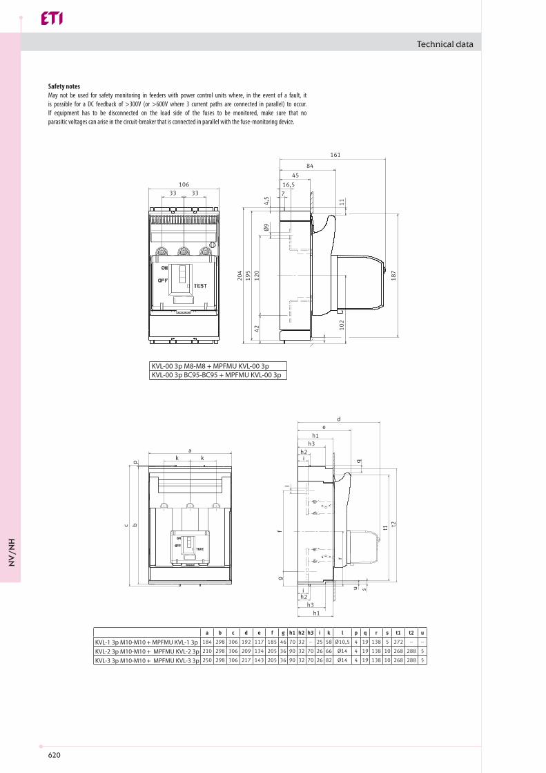
KVL-00 3p M8-M8 + MPFMU KVL-00 3pKVL-00 3p BC95-BC95 + MPFMU KVL-00 3p
d
q
lf
g
u
r
s
e
i
i
c bp
ak k
KVL-1 3p M10-M10 + MPFMU KVL-1 3p KVL-2 3p M10-M10 + MPFMU KVL-2 3p KVL-3 3p M10-M10 + MPFMU KVL-3 3p
Technical data
Safety notesMay not be used for safety monitoring in feeders with power control units where, in the event of a fault, it is possible for a DC feedback of >300V (or >600V where 3 current paths are connected in parallel) to occur. If equipment has to be disconnected on the load side of the fuses to be monitored, make sure that no parasitic voltages can arise in the circuit-breaker that is connected in parallel with the fuse-monitoring device.
NV
/NH
621
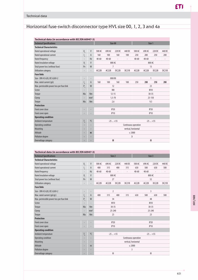
Ue V 500 AC 690 AC 220 DC 440 DC 500 AC 690 AC 220 DC 440 DCIe A 160 100 160 100 250 200 250 200- Hz 40-60 40-60 - - 40-60 40-60 - -Ui V 800 AC 800 ACPv W 7 13- - AC22B AC22B DC22B DC21B AC22B AC22B DC22B DC21B
- - 000/00 1In A 160 100 160 100 250 200 250 200Pv W 12 23- - M8 M10
Ma Nm 12-15 30-35- mm2 1,5-70 25-150
Ma Nm 2,6 9,5
- - IP20 IP20- - IP10 IP10
TuOC -25 ... +55 -25 ... +55
- -- -- m ≤ 2000- - 3- - III III
Ue V 500 AC 690 AC 220 DC 440 DC 500 AC 690 AC 220 DC 440 DCIe A 400 315 400 315 630 500 630 500- Hz 40-60 40-60 - - 40-60 40-60 - -Ui V 800 AC 800 ACPv W 27 52- - AC22B AC22B DC22B DC21B AC22B AC22B DC22B DC21B
- - 2 3In A 400 315 400 315 630 500 630 500Pv W 34 48- - M10 M10
Ma Nm 30-35 30-35- mm2 25-240 25-240
Ma Nm 23 23
- - IP20 IP20- - IP10 IP10
TuOC -25 ... +55 -25 ... +55
- -- -- m ≤ 2000- - 3- - III III
Technical data
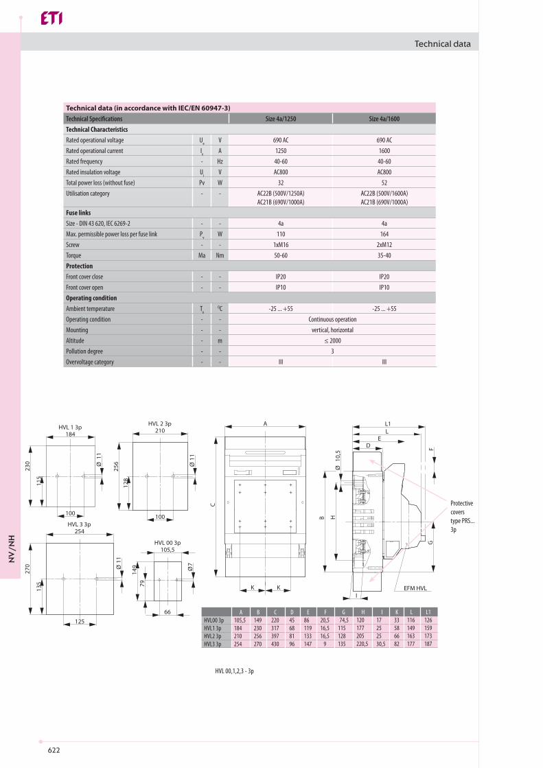
Horizontal fuse-switch disconnector type HVL size 00, 1, 2, 3 and 4a
Technical data (in accordance with IEC/EN 60947-3)Technical Specifications Size 00 Size 1Technical CharacteristicsRated operational voltageRated operational currentRated frequencyRated insulation voltageTotal power loss (without fuse) Utilisation categoryFuse linksSize - DIN 43 620, IEC 6269-2Max. rated current (gG) 200 250 200Max. permissible power loss per fuse linkScrewTorqueClampTorqueProtectionFront cover closeFront cover open Operating conditionAmbient temperatureOperating condition - - Continuous operationMounting - - vertical, horizontalAltitude - mPollution degree - - 3Overvoltage category - - III III
Technical data (in accordance with IEC/EN 60947-3)Technical Specifications Size 2 Size 3Technical CharacteristicsRated operational voltageRated operational currentRated frequencyRated insulation voltageTotal power loss (without fuse)Utilisation categoryFuse links
Size - DIN 43 620, IEC 6269-2Max. rated current (gG/gL)Max. permissible power loss per fuse linkScrewTorqueClampTorqueProtectionFront cover closeFront cover openOperating conditionAmbient temperatureOperating condition Continuous operationMounting vertical, horizontalAltitudePollution degreeOvervoltage category
NV
/NH
622
Ue V 690 AC 690 ACIe A 1250 1600- Hz 40-60 40-60Ui V AC800 AC800Pv W 32 52- - AC22B (500V/1250A)
AC21B (690V/1000A)AC22B (500V/1600A)AC21B (690V/1000A)
- - 4a 4aPv W 110 164- - 1xM16 2xM12
Ma Nm 50-60 35-40
- - IP20 IP20- - IP10 IP10
TuOC -25 ... +55 -25 ... +55
- -- -- m ≤ 2000- - 3- - III III
HVL 1 3p184
HVL00 3pHVL1 3pHVL2 3pHVL3 3p
105,5184210254
A149230256270
B220317397430
C45688196
D86119133147
E20,516,516,5
9
F74,5
115128135
G17252530,5
I33586682
K116149163177
L126159173187
L1120177205220,5
H
HVL 2 3p210
HVL 3 3p254
HVL 00 3p105,5
100 100
125
66
A L1L
ED
K KI
EFM HVL
032
652
511
11 11
82111 7
5,01
072
531
94197
C
B H
GF
HVL 00,1,2,3 - 3p
Technical data
Technical data (in accordance with IEC/EN 60947-3)Technical Specifications Size 4a/1250 Size 4a/1600Technical CharacteristicsRated operational voltageRated operational currentRated frequencyRated insulation voltageTotal power loss (without fuse)Utilisation category
Fuse linksSize - DIN 43 620, IEC 6269-2Max. permissible power loss per fuse linkScrewTorqueProtectionFront cover closeFront cover openOperating conditionAmbient temperatureOperating condition Continuous operationMounting vertical, horizontalAltitudePollution degreeOvervoltage category
Protective covers type PRS... 3p
NV
/NH
623
49
49
941
7
022
941
021
97
25
9
45
86
17
02
HVL 00 1-p
332
312218
155
40 13
155
1250A 1600A
96
216250
4545
161634 34
Ø13
Ø16
30
185
344
Ø13
30
25Ø16 7 7 25
338 41
9C
B
350
1600A1250A 270
311315339
CB
50
50
M12
M16
22
C22
B 67
14
55
BC
22.5
257
185
30
344
419
CB
350
15596
40 13
155218108
116
45
3416
Ø16
Ø13
1250A1600A
270311
315339
CB
55
22.5
C B
50
1250A
M16
C 2214
67B
1600A
50
22M12
HVL 4 3p
HVL 4 1-p
332
312218
155
40 13
155
1250A 1600A
96
216250
4545
161634 34
Ø13
Ø16
30
185
344
Ø1330
25Ø16 7 7 25
338 41
9C
B
350
1600A1250A 270
311315339
CB
50
50
M12
M16
22
C22
B 67
14
55
BC
22.5
332
312218
155
40 13
155
1250A 1600A
96
216250
4545
161634 34
Ø13
Ø16
30
185
344
Ø13
30
25Ø16 7 7 25
338 41
9C
B
350
1600A1250A 270
311315339
CB
50
50
M12
M16
22
C22
B 67
14
55
BC
22.5
Technical data
Protective covers type PRS 00 MB 1p
NV
/NH

624
HVL 391
HVL 1HVL 3
6991
A230270
B317430
C6896
D2530,5
I119147
E115135
G177220,5
H16,5
9
F
HVL 169
072
032 525,201
525,221
5,01
5,01
30
30B
C
H
G
A D
E
5,01
I
F
HVL 1 & HVL 3
98
49
25
97
7
9
941 022
98
89
4532
5,47
941
021
17
HVL00 2P M8-M8
Technical data
Protective covers type PRS 1,3 MB 1p
Protective covers type PRS 00 MB 1p
Protective covers type PRS 00 MB 1p
NV
/NH

625
HVL1 2P M10-M10138
HVL3 2P M10-M10182
9169
072531
HVL1 2P M10-M10HVL3 2P M10-M10
138182
A230270
B317430
C6896
D123,5151,5
E2315,5
F115135
G177220,5
H2530,5
I
81
5,41
5,01
032511
A D
I
E
C B H
F
HVL1, 3 2P M10-M10
154,5
7
941
97
66
77,3 24,5 33 33
25
7
022
154,5 45
941
021
5,47
9
32
89
17
HVL00 4P M8-M8
Technical data
Protective covers type PRS 1,3 MB 1p
Protective covers type PRS 1,3 MB 1p
Protective covers type PRS 00 MB 1p + PRS 00 3p
Protective covers type PRS 00 MB 1p + PRS 00 3p
NV
/NH

626
HVL1 4P M10-M10253 A E
D
F
HVL3 4P M10-M10345
100 34,576,5
032
511
1111
81
072
531
5,41
5,01
C
K K
HVL1 4P M10-M10HVL3 4P M10-M10
253345
A230270
B317430
C6896
D123,5151,5
E2315,5
F115135
G177220,5
H2530,5
I5882
K
125 110 45,5
B H
G
I
HVL1, 3 4P M10-M10
HVL 1 3p184
HVL00 3pHVL1 3pHVL2 3pHVL3 3p
105,5184210254
A149230256270
B220317397430
C45688196
D86119133147
E20,516,516,5
9
F74,5
115128135
G17252530,5
I33586682
K116149163177
L126159173187
L1120177205220,5
H
HVL 2 3p210
HVL 3 3p254
HVL 00 3p105,5
100 100
125
66
A L1L
ED
K KI
EFM HVL
032
652
511
11 11
82111 7
5,01
072
531
94197
C
B H
GF
HVL 00, 1, 3 – 3p EFM
Technical data
Protective covers type PRS 1,3 MB 1p + PRS 1,3 3p
Protective covers type PRS 1,3 MB 1p + PRS 1,3 3p
Protective covers type PRS 00,1,2,3
NV
/NH

627
5A / AC 250V0,35A / DC 110V0,1A / DC 250V
1
2
4
Break o� the part on the top protective cover
5A / AC 250V0,35A / DC 110V0,1A / DC 250V
1
2
4
Technical data
NV
/NH

628
HVL EK 000 1p HVL EK 000 3p HVL EK 00 1p HVL EK 00 3pIth A 160Ui V AC 690
Uimp kV 6
Hz 50 ( 40-60 )AC-21B AC-22B AC-21B AC-22B AC-21B AC-22B AC-21B AC-22B
Ie A 160 125 160 100 160 125 160 125Ue V 230 AC 690 AC 400 AC 500 AC 230 AC 690 AC 400 AC 500 AC
kAeff 631600200
W 3,74 10,2 3,74 10,2IP20IP10
3OC -25 ÷ +55OC -30 ÷ +70
2 - 3 4 - 5 6 - 9 >90,9 0,8 0,7 0,6
HVL EK 000 1p
O6, 5
O6,5
2538
6*1
49
78,5
69,5
9 1
178
60°
Technical data
Technical dataTechnical SpecificationsConventional free air thermal current*Rated insulation voltageRated withstand voltage
Rated frequencyUtilisation category Rated operational current Rated operational voltageRated conditional short-circuit currentMechanical durability (operating cycles)Electrical durability (operating cycles)Power dissipation (without fuse)Degree of protection (cover closed)Degree of protection (cover open)Pollution degreePermissible ambient temperature**Storage temperature
* In case of mounting of the fuse-switch disconnector in cabinet, the thermal current should be corrected (Ith x derating factor), depending on the number of built apparatuses (see table 1)** In case of using the fuse-switch disconnector at temperatures +450C to +550C, the thermal current Ith should be reduced for 5%-10%
Table 1Number of built apparatusesDerating factor
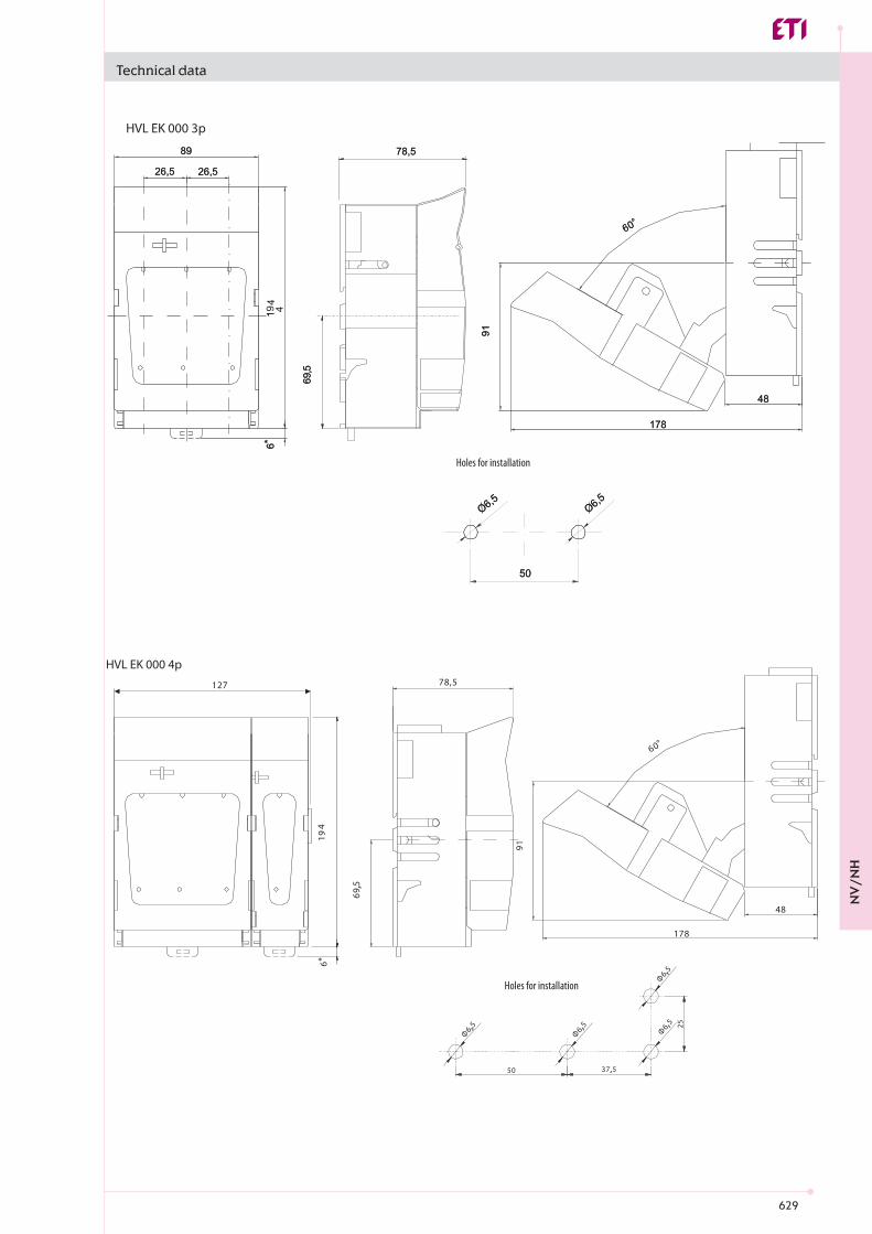
Horizontal fuse-switch disconnector type HVL EK size 000 and 00
Holes for installation
NV
/NH
629
HVL EK 000 3p
OO66,,55OO66,,55
5500
8899
2266,,55 2266,,55
66**11 4
49
99 11
117788
4488
6600°°
7788,,55
6699,,55
HVL EK 000 4p
91
178
48
60°
78,5
69,5
127
6*1
49
50 37,5
25
Φ6,5
Φ6,5
Φ6,5
Φ6,5
Technical data
Holes for installation
Holes for installation
NV
/NH

630
Mounting-rail 35mm
MS -set
1
4
3
2
HVL-B EK 000 3p
158,
5
89
26,5 26,5
19 ,35 - 10
max 23,3 / 25,3
6060
6
12 mm
1 5 mm
20 mm
25 mm
30 mm
9
89,9
1
Technical data
HVL EK 000 – options and Installation guide
NV
/NH

631
( 106 )
( 187 )
( 33 )
( 80
)protective cap
O6,5O6,5
50
186
91
60
49
7
52
80
4,5
25
O7
42
159
1 71*
HVL EK 00 1p
HVL-P EK 000 3P
Technical data
Holes for installation
HVL-P EK 000 3p is supplied complete with a bottom covering protection. HVL-P EK 00 3p is supplied without protective coatings.
Holes for installation NV
/NH

632
HVL EK 00 3p
106
33 33
159
1 71*
186
91
60°
66
7
75
60
25
O
3.5R
49
752
80
4,5
186
91
60°
49
7
52
80
4,5
148
33 33
159
1 71*
HVL EK 00 4p
66
O7
75
60
25
3.5R
25
O7
28,5
Technical data
Holes for installation
Holes for installation
* with set for mounting on two mounting rails in distance (125mm, 150mm)
NV
/NH


![MCCBs - electricpwr.com · MCCBs Low Voltage Products ... Interrupting ratings B N S H N S N H L N H L 240V AC [kA rms] 50 2 65 150 50 65 65 100 150 65 100 150 277V AC [kA rms] 18](https://img.dokumen.tips/doc/110x75/5aed831f7f8b9a3b2e90b28b/mccbs-low-voltage-products-interrupting-ratings-b-n-s-h-n-s-n-h-l-n-h-l-240v.jpg)