Embed Size (px)
Citation preview

MARINE RADAR MODEL1823C MARINE RADAR MODEL1833C MARINE RADAR MODEL1933C MARINE RADAR MODEL1943C MARINE RADAR MODEL1953C
COLOR VIDEO PLOTTER GD-1900C

i
WARNINGRadio FrequencyRadiation Hazard
The radar antenna emits electromagneticradio frequency (RF) energy which can beharmful, particularly to your eyes. Neverlook directly into the antenna aperture froma close distance while the radar is inoperation or expose yourself to the trans-mitting antenna at a close distance.
Distances at which RF radiation levels of100 and 10 W/m2 exist are given in thetable below.
Note: If the antenna unit is installed at aclose distance in front of the wheel house,your administration may require halt oftransmission within a certain sector ofantenna revolution. This is possible - Askyour FURUNO representative or dealer toprovide this feature.
MODELDistance to
100 W/m2
point
Distance to10 W/m2
point
MODEL1833C
NilWorst case
0.50 m
SAFETY INSTRUCTIONS
Do not open the equipmentunless totally familiar withelectrical circuits andservice manual.
Only qualified personnel should work inside the equipment.
Wear a safety belt and hardhat when working on theantenna unit.
Serious injury or death canresult if someone falls fromthe radar mast.
WARNING
Construct a suitable service platformfrom which to install the antenna unit.
Serious injury or death can result if some-one falls from the radar mast.
Turn off the power at the mains switch-board before beginning the installation.
Fire, electrical shock or serious injury canresult if the power is left on or is appliedwhile the equipment is being installed.
ELECTRICALSHOCK
HAZARD
MODEL1933C
MODEL1943C
NilWorst case
3.00 m
NilWorst case
2.50 m
Observe the following compass safedistances to prevent deviation of a magnetic compass.
Standard SteeringDisplay unit
MODEL1833C antenna unit
MODEL1933C antenna unit MODEL1943C antenna unit
0.60 m 0.40 m
0.90 m 0.70 m1.00 m1.00 m
0.80 m0.80 m
CAUTIONGround the equipment toprevent electrical shock andmutual interference.
MODEL1953C antenna unit 1.00 m 0.75 m
MODEL1953C
XN12A
XN13A
Nil
Worst case2.50 m
Worst case2.30 m
Power supply unit (1953C) 1.40 m 0.95 m
MODEL1823C antenna unit 1.25 m 0.85 m
MODEL1823C
NilWorst case
0.50 m
Memory card IF unit(option) 0.90 m 0.60 m

ii
TABLE OF CONTENTS
SAFETY INSTRUCTIONS........................................................................................ i
EQUIPMENT LISTS ................................................................................................. iii
SYSTEM CONFIGURATIONS.................................................................................. v
1. MOUNTING .......................................................................................................... 1-11.1 Installation of Display Unit ..........................................................................................................1-1 1.2 Mounting of Antenna Unit for MODEL1833C...............................................................................1-4 1.3 Mounting of Antenna Unit for MODEL1933C/1943C/1953C ........................................................1-11 1.4 Mounting of Power Supply Unit for MODEL1953C......................................................................1-20 1.5 Mounting of Antenna Unit for MODEL1823C...............................................................................1-21
2. WIRING ................................................................................................................ 2-12.1 Standard Wiring .........................................................................................................................2-1 2.2 External Buzzer (OP03-136, option) Connection.........................................................................2-4 2.3 How to Connect with PC ...........................................................................................................2-5 2.4 Wiring of Power Supply Unit (MODEL1953C only)......................................................................2-6 2.5 Connection of CU-200 (option) ...................................................................................................2-8
3. ADJUSTMENT ..................................................................................................... 3-13.1 How to Access to Installation Menu ............................................................................................3-1 3.2 NETWORK SETUP Menu ..........................................................................................................3-2 3.3 RADAR SETUP Menu................................................................................................................3-4 3.4 Checking Magnetron Heater Voltage ..........................................................................................3-11 3.5 Navigation Data Source .............................................................................................................3-11 3.6 Setting up Data Ports .................................................................................................................3-16 3.7 Remote Controller Setting ..........................................................................................................3-18 3.8 Remote Display Setting..............................................................................................................3-19
4. OPTIONS.............................................................................................................. 4-14.1 ARP Kit ARP-11..........................................................................................................................4-1 4.2 Connection of Video equipment/External Monitor/Remote Display ..............................................4-4 4.3 Mounting the Memory Card Interface Unit ..................................................................................4-10
PACKING LISTS ...................................................................................................... A-1
OUTLINE DRAWINGS ............................................................................................. D-1
INTERCONNECTION DIAGRAMS........................................................................... S-1
iii
EQUIPMENT LISTS Standard supply
Name Type Code No. Qty RemarksRDP-138* - Normal bright LCD, 300 Cd Display unit RDP-139 - 1 High bright LCD, 700 CdRSB-0094-0075 - MODEL 1823CRSB-0071-057 - MODEL 1833C
XN10A-RSB-0070-064 - MODEL1933C, 24 rpm, for RDP-138/139
XN10A-RSB-0073-064 - MODEL1933C, 48 rpm, for RDP-138
XN12A-RSB-0070-059 - MODEL1943C, 24 rpm XN12A-RSB-0073-059 - MODEL1943C, 48 rpm XN12A-RSB-0072-060 - MODEL1953C, 4”, 24 rpm XN12A-RSB-0073-060 - MODEL1953C, 4”, 48 rpm
Antenna unit
XN13A-RSB-0072-060 -
1
MODEL1953C, 6”, 24 rpm Power supply unit PSU-005 - 1 For MODEL1953C Remote controller set RMC-100 000-089-885 1 Remote controller, vinyl case,
battery, labels
CP03-22700 000-080-049 1setFor display unit, MJ-A3SPF0018-050Z cable, CP03-22701
CP03-25401 008-443-160 1set For MODEL1823C antenna unit
CP03-16901 008-478-750 1set For MODEL1833C antenna unit
CP03-21800 000-080-014 For MODEL1823C/1833C 10 m signal cable
CP03-21810 000-080-015 For MODEL1823C/1833C 15 m signal cable
CP03-21820 000-080-016 For MODEL1823C/1833C 20 m signal cable
CP03-21830 000-080-017
1
For MODEL1823C/1833C 30 m signal cable
CP03-22000 000-080-021 For 1933C/1943C/1953C 10 m signal cable
CP03-22010 000-080-022 For 1933C/1943C/1953C 15 m signal cable
CP03-22020 000-080-023 For 1933C/1943C/1953C 20 m signal cable
CP03-22030 000-080-024
1
For 1933C/1943C/1953C 30 m signal cable
CP03-18401 008-503-360 1 For 1933C/1943C/1953C antenna unit
CP03-22901 008-523-690 1 For 1933C/1943C/1953C antenna radiator XN10A/XN12A
Installation materials
CP03-24500 000-080-191 1 For 1953C, power supply unit Accessories FP03-09301 008-522-970 1set Card remover
SP03-14001 000-080-018 1set Fuses, for display unit Spare parts SP03-14001 000-080-018 1set Fuses, for power supply unit
(1953C only) *Not available for MODEL 1953C

iv
Optional supply Name Type Code No. Qty Remarks
000-013-484 For GD-1900C, 100 VAC 000-013-485 For GD-1900C, 110 VAC 000-013-486 For GD-1900C, 220 VAC
PR-62
000-013-487
1
For GD-1900C, 230 VAC Rectifier
RU-3423 000-030-443 1 For MODEL series External buzzer OP03-136 000-086-443 1
MJ-A6SPF0014-010 000-144-421 1 For NavNet, 1 m MJ-A6SPF0014-050 000-144-422 1 For NavNet, 5 m MJ-A6SPF0014-100 000-144-423 1 For NavNet, 10 m MJ-A6SPF0014-200 000-144-424 1 For NavNet, 20 m MJ-A6SPF0014-300 000-144-425 1 For NavNet, 30 m MJ-A6SPF0012-050 000-134-424 1 For navaid, 5 m MJ-A6SPF0012-100 000-133-817 1 For navaid, 10 m MJ-A6SPF0003-050 000-117-603 1 w/6P connector, 5 m MJ-A6SPF0009-100 000-125-236 1 w/6P connector, 10 m MJ-A6SPF0007-100 000-125-237 1 For compass, 10 m
MJ-A7SPF0007-050 000-144-418 1 For external buzzer, PC, w/7P connector, 5 m
MJ-A6SRMD/TM11AP8-005 000-144-463 1 Adapter cable for HUB MJ-B24LPF0008-100 000-145-125 1 For remote display, 10 m MJ-B24LPF0008-200 000-145-126 1 For remote display, 20 m
Cable assy.
MJ-B24LPF0008-300 000-145-127 1 For remote display, 30 m RGB output cable kit OP03-176 008-526-360 1 For external monitor
ARP kit ARP-11 008-523-050 1 ARP Board, for radar only NTSC/PAL interface kit OP03-175 008-523-070 1 Connection video source
Mounting bracket (1) OP03-92 008-445-070 1 For MODEL1833C
Mounting bracket (2) OP03-93 008-445-080 1 For MODEL1823C
Chart card - - - Specified when ordering. RAM card 00RAM02MC-004 004-371-790 1 2 MB Remote controller set RMC-100 000-089-885 1
Modification kit for C-map MODEL17*2/C-MAP 008-525-200 1 See modification instruction
E42-00005-x EMI core E04R241336A 000-146-335 1 For remote display cable connectionMemory card interface unit CU-200-NAV 000-081-567 1 w/two chart card slots

v
SYSTEM CONFIGURATIONS All NavNet products incorporate a “network circuit board” to integrate each NavNet product on board through an optional LAN cable (Ethernet 10BASE-T). Each NavNet product is assigned an IP address to enable transfer of images between other NavNet products. For example, video plotter pictures can be transferred to a radar and vice versa. Pictures received via the NavNet may be adjusted at the receiving end.
The number of display units which may be installed depends on the number of network sounder connected. For a system incorporating three or more products, a “hub” is required to process data.
For one network sounder: one radar and three plotters, or four plotters For two network sounder: one radar and two plotters, or four plotters
Heading sensor
External buzzerPCEcho sounder
RectifierRU-3423
Echo sounderNavigator
GPS receiverGP-310B/320B
12 - 24 VDC**
Network Sounder
ETR-6/10NETR-30N
Other NavNet unit(GD-1900C etc.)
Antenna Unit
MODEL1833C
MODEL1933C
MODEL1943C
Display unitRDP-138*/139
100/110/115/220/230 VAC1φ, 50/60 Hz**
VGA monitorRemote displayVideo equipment
MODEL1953C
Power Supply Unit PSU-005
*: Not available for MODEL 1953C.**: The power for the power supply unit and display unit must be drawn from the same power source.
FacsimileReceiverFAX-30
MODEL1823C
Memory card interface unit CU-200
12 VDC
Figure 1 (a) NavNet system (MODEL1823C/1833C/1933C/1943C/1953C)

vi
Network SounderETR-6/10NETR-30N
GPS receiverGP-310B/320B
12 - 24 VDC
Other NavNet Unit(Model 1833C, etc.)
Display unitRDP-138/139
Ship's mains100/110/115/220/230 VAC1φ, 50/60 Hz: Standard
: Option
RemoteControllerRMC-100
External buzzerPCEcho sounder
EchosounderNavigator
RectifierPR-62
VGA monitorRemote displayVideo equipment
FacsimileReceiverFAX-30
Memory card interface unit CU-200
12 VDC
Figure 1 (b) NavNet system (GD-1900C)

vii
Figure 2 (a) NavNet system, three-unit connection
HUB
Network SounderETR-6/10NETR-30N(option)
Radar Antenna UnitOR
GPS Receiver GP-310B/320B
Radar Antenna UnitOR
GPS Receiver GP-310B/320B
RADARor
PLOTTER
RADARor
PLOTTER
Sounder data
Radar data Plotter data
Note: The picture disappears10 seconds after the NavNetcable is disconnected from a"sub" NavNet display unit.
Network SounderETR-6/10NETR-30N(option)
FacsimileReceiverFAX-30(option)
Sounder data
Facsimiledata
Figure 2 (b) NavNet system, two-unit connection

1-1
1. MOUNTING
1.1 Installation of Display Unit The display unit can be installed on a tabletop, on the overhead or flush mounted in a console or panel.
Tabletop, overhead mounting method
When selecting a mounting location for the display unit keep the following in mind:
• Keep the display unit out of direct sunlight.
• The temperature and humidity should be moderate and stable.
• Locate the unit away from exhaust pipes and vents.
• The mounting location should be well ventilated.
• Mount the unit where shock and vibration are minimal.
• Keep the unit away electromagnetic field generating equipment such as motor, generator.
• For maintenance and checking purposes, leave sufficient space at the sides and rear ofthe unit and leave slack in cables.
• A magnetic compass will be affected if the display unit is placed too close the magneticcompass. Observe the following compass safe distances to prevent disturbance to themagnetic compass.
Standard compass: 0.60 m
Steering compass: 0.40 m

1-2
1.1.1 Mounting procedure
Tabletop, overhead mounting
Follow the procedure below to mount the display unit on a tabletop or the overhead.
1. Fix the hanger by four tapping screw (5x20).2. Screw knob bolts in display unit, set it to hanger, and tighten knob bolts.3. Attach hard cover to protect LCD.
Tapping screws (4 pcs.)
Knob bolts (2 pcs.)
Display unit
Hanger
Tabletop, overhead mounting of display unit
Note: For the overhead mounting, reinforce the mounting location and secure the hanger, with bolts, nuts and washers (local supply).

1-3
Flush mounting
Note: Use supplied six pan head screws when the thickness of the bulkhead is from 11 to 14 mm. For bulkhead which exceeds 14 mm in thickness the length of the pan head screws should be bulkhead thickness (A) plus 7.8±2 mm. Also the length of B should be max. 8 mm.
AB
A: thickness of bulkhead
Fixing screw, side view
1. Prepare a cutout in the mounting location by using the template sheet supplied as theinstallation material.
2. Fix the display unit by six washer head screws M4x20. Refer to the outline drawing atback of this manual.
335+1
6-R2.25 342+0.5
4.5
217+
0.5
140+
0.5
209+
1
Flush mounting of display unit
Note: When installing the display unit in a panel, attach the vinyl tube (Ф6, local supplied) to the drain hole to allow moisture to escape. Then fasten the tube to the drain hole with a cable tie.

1-4
1.2 Mounting of Antenna Unit for MODEL1833C 1.2.1 Mounting considerations
When selecting a mounting location for the antenna unit keep in mind the following points.
• Install the antenna unit on the hardtop, radar arch or on a mast on an appropriateplatform. (For sailboats, a mounting bracket is optionally available.) It should be placedwhere there is a good all-round view with, as far as possible, no part of the ship’ssuperstructure or rigging intercepting the scanning beam. Any obstruction will causeshadow and blind sectors. A mast, for instance, with a diameter considerably less thanthe width of the antenna unit, will cause only a small blind sector. However, a horizontalspreader or crosstrees in the same horizontal plane would be a much more seriousobstruction; place the antenna unit well above or below it.
Antenna unit
Antenna unit
Antenna unit
Antenna unit
Typical antenna unit placement on sailboat and powerboat
• In order to minimize the chance of picking up electrical interference, avoid where possiblerouting the antenna cable near other electrical equipment onboard. Also avoid runningthe cable in parallel with power cables.
• The compass safe distance of 0.90 meters (standard compass) and 0.70 meters (steeringcompass) should be observed to prevent deviation of the magnetic compass.
1-5
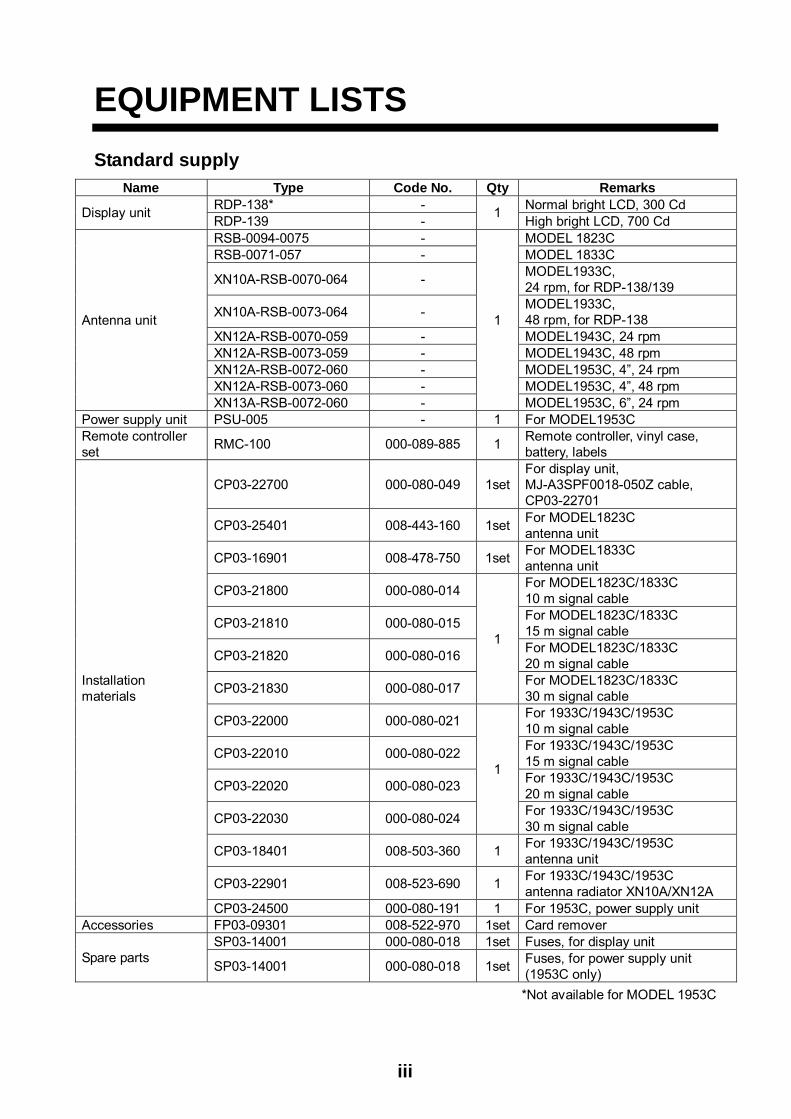
1.2.2 Mounting antenna unit of MODEL 1833C
1. Open the antenna unit packing box carefully.2. Unbolt the four bolts at the base of the radome to remove the radome cover.
Radome cover
Antenna unit
The mounting surface must be parallel with the waterline and provided with five holes (four fixing holes and one cable entry) whose dimensions are shown in the outline drawing attached at the end of this manual. The unit is adjusted so a target echo returned from the bow direction will be shown on the zero degree (heading line) position on the screen. When drilling holes, be sure they are parallel with the fore and aft line.
3. Prepare a platform of 5 to 10 millimeters in thickness for the antenna unit.A mounting bracket for mounting the antenna unit on a sailboat mast is optionallyavailable. (Refer to page 1-9.) Find the cable entry on the radome base. Next, positionthe radome base so the cable entry faces the stern direction. This alignment must be asaccurate as possible.
Flat washerSpring washerM10 x 25 Hex bolt Platform
4- 12 Holes
Cableentry
Ship's bow
Antenna unit, cover removed

1-6
Flatwasher
Springwasher
Platform
Antenna base plate
M10 x 25Hex bolt
Radome
5 - 10 mm
Apply silicone sealant.
Effectivethread length
25 mm
Gasket
How to fasten the radome base to the mounting platform
Wiring and final preparation
4. Drill a hole of at least 20 millimeters diameter through the deck or bulkhead to run thesignal cable between the antenna unit and the display unit. (To prevent electricalinterference avoid running the signal cable near other electrical equipment and inparallel with power cables.) Pass the cable through the hole. Then, seal the hole withsealing compound for waterproofing.
5. Remove two shield covers in the radome.6. Remove the cable clamping plate by unfastening four screws and removing a gasket.
Shield cover
Shield cover
Pan head screwsM4x8 7 pcs.
Pan head screwsM4x8 7 pcs.
Pan head screwsM4x8 4 pcs.
Gasket
Cable clamping plate
Antenna unit, inside view
7. Pass the cable through the hole at the bottom of the radome base.8. Secure the cable with the cable clamping plate and gasket. Ground the shield wire by
one of the screws of the cable clamping plate.

1-7
9. Attach three connectors of the signal cable to respective ports as shown below.
to one of the screws of the cable clamping plate
9-pin connector:to J801 on MD-9208
4-pin connector:to J802 on MD-9208
13-pin connector:to J611 on IF-9214
Signal cable, antenna unit side
J802J801
J611
MD-9208
IF-9214
PTU-9335
Cableentry
RF unit

1-8
10. Attach the EMI cores supplied as shown below.
J806
J805
J803
J804
J802J801
Motor
J613
J611
J1
EMI coreE04SS251512(Above cableclampingplate)
Cableentrance
IF9214IF9214APTU-9335
MD-9208
Cableclamping plate
How to attach EMI core 11. Fix the shield cover. Do not pinch the cable.12. Attach the radome cover, aligning triangle mark on radome cover with that on radome
base.
Radome cover
Radome baseHow to position the radome cover
13. Loosely fasten the radome fixing bolts. You will tighten them after confirming magnetronheater voltage.

1-9
1.2.3 Mounting the optional mounting bracket
A mounting bracket for fastening the antenna unit for MODEL1833C to a mast on a sailboat is optionally available.
Mounting bracket 1
Type: OP03-92 Code No.: 008-445-070
Table 1-1 Mounting bracket contents
Type Code No. Qty
Hex. bolt M4X12 000-804-725 4
Hex. bolt M8X20 000-805-707 8
Mounting plate 03-018-9001-0 100-206-740 1
Support plate (1) 03-018-9005-0 100-206-780 1
Support plate (2) 03-018-9006-0 100-206-790 1
Bracket (1) 03-018-9002-1 100-206-751 1
Bracket (2) 03-018-9003-1 100-206-761 1
Fixing plate 03-018-9004-1 100-206-771 2
Assemble the mounting bracket and fasten it to a mast. Fasten the antenna unit to the bracket.

1-10
Mounting plate
Support plate (1)
Support plate (2)
Bracket (1)
Bracket (2)
Fixing plateM8 x 20
M8 x 20
M4 x 12
M10 x 25 (supplied with antenna unit)
M8 x 20
(A) Assembling the mounting bracket
(B) Fastening antenna to mounting bracket
How to assemble and mount the optional mounting bracket
1-11
1.3 Mounting of Antenna Unit for MODEL1933C/1943C/1953C
1.3.1 Mounting considerations
• The antenna unit is generally installed either on top of the wheelhouse or on the radarmast on a suitable platform. Locate the antenna unit where there is a good all-round view.Any obstruction will cause shadow and blind sectors.A mast for instance, with a diameter considerably less than the width of the radiator, willcause only a small blind sector, but a horizontal spreader or crosstrees in the samehorizontal plane as the antenna unit would be a much more serious obstruction; youwould need to place the antenna unit well above or below it.
• It is rarely possible to place the antenna unit where a completely clear view in alldirections is available. Thus, you should determine the angular width and relative bearingof any shadow sectors for their influence on the radar at the first opportunity after fitting.
• If you have a radio direction finder on your boat, keep the antenna unit from its antennamore than two meters to prevent the interference to the direction finder.
• To lessen the chance of picking up electrical interference, avoid where possible routingthe signal cable near other onboard electrical equipment. Also avoid running the cable inparallel with power cables.
• A magnetic compass will be affected if the antenna unit is placed too close to the magnetcompass. Observe the following compass safe distances to prevent deviation of amagnetic compass: Standard compass, 1.00 m, Steering compass, 0.80 m (1953C: 0.75m).
• Do not paint the radiator aperture, to ensure proper emission of the radar waves.
a) When this radar is to be installed on larger vessels, consider the following points:The signal cable run between the antenna and the display comes in lengths of 10 m, 15m, 20 m and 30 m. Whatever length is used it must be unbroken; namely, no splicingallowed.
b) Deposits and fumes from a funnel or other exhaust vent can adversely affect the aerialperformance and hot gases may distort the radiator portion. The antenna unit must notbe mounted where the temperature is more than 70°C.
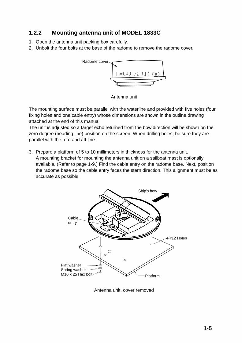
As shown in the figure below, the antenna unit may be installed on the bridge, on a common mast or on the radar mast.
(a) On bridge (b) Common mast (c) Radar mast

1-12
1.3.2 Mounting antenna unit of MODEL 1933C/1943C/1953C
Referring to the outline drawing at the back of this manual, drill five holes in the mounting platform: four holes of 15 mm diameter for fixing the antenna unit and one hole of 25-30 mm diameter for the signal cable.
Fastening the Radiator to the Radiator Bracket
For your reference, antenna installation materials list appears in the packing lists at the back of this manual (see page A-6 to A-11).
1. Remove the radiator cap from the radiator bracket.2. Coat contacting surface between antenna radiator and radiator bracket with silicone
sealant as shown in figure below.
Coat hatched area withsilicone sealant.
Groove
Radiator
RADIATOR BRACKET(top view)
Coat hatched area withanticorrosive sealant.
10mm
(MODEL 1933C) (MODEL 1943C/1953C)
ANTENNA RADIATOR(bottom view)
Coating the antenna with silicone sealant
3. Coat threaded holes on the antenna radiator with silicone sealant.4. Grease the O-ring and set it to the radiator bracket.5. Lay the antenna radiator on the radiator bracket.6. Coat the radiator fixing bolts (4 pcs.) with silicone sealant. Fasten the antenna radiator to
the radiator bracket with the radiator fixing bolts, flat washers and spring washers.
Flat washerSpring washerHex head bolt(M8 x 30)
Radiator bracket
Coat bolts withsilicone sealant.
Antennaradiator
O-ring
Coat threadedholes with siliconesealant.
Fastening the radiator bracket to the antenna unit chassis
1-13
Mounting of antenna unit
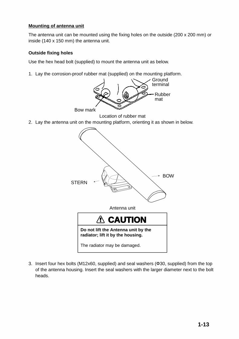
The antenna unit can be mounted using the fixing holes on the outside (200 x 200 mm) or inside (140 x 150 mm) the antenna unit.
Outside fixing holes
Use the hex head bolt (supplied) to mount the antenna unit as below.
1. Lay the corrosion-proof rubber mat (supplied) on the mounting platform.Groundterminal
Rubbermat
Bow markLocation of rubber mat
2. Lay the antenna unit on the mounting platform, orienting it as shown in below.
STERNBOW
Antenna unit
CAUTIONDo not lift the Antenna unit by the radiator; lift it by the housing.
The radiator may be damaged.
3. Insert four hex bolts (M12x60, supplied) and seal washers (Ф30, supplied) from the topof the antenna housing. Insert the seal washers with the larger diameter next to the boltheads.

1-14
Hex bolt
Seal washer
Flat washerSpring washer
Nut
Fixing the antenna unit chassis
4. Pass flat washers (M12, supplied), spring washers (M12, supplied) and nuts (M12,supplied) onto hex bolts. Fasten by tightening nuts. Do not fasten by tightening the hexbolts; seal washers may be damaged.
AntennaunitMountingplatform
Siliconesealant
Flat washer
Rubber mat
Seal washer
How to fasten antenna unit to mounting platform
5. Coat flat washers, spring washers, nuts and exposed parts of bolts with anticorrosivesealant.
6. Prepare ground point in mounting platform (within 300 mm of ground terminal onantenna unit) using M6 x 25 bolt, nut and flat washer (supplied).
7. Run the ground wire (RW-4747, 340 mm, supplied) between the ground terminal andground point.
8. Coat ground terminal and ground point with silicone sealant as shown on the next page.

1-15
Groundwire
Hex boltFlat washer
Spring washerFlat washer
Hex nutSiliconesealant
Hex nut
Weld here.
Siliconesealant
Groundwire
antennaunit
OR
Flat washerSpring washer
Groundwire
GROUNDTERMINAL
GROUNDPOINT
Hex nut
How to coat ground point and ground terminal with silicone sealant

1-16
Fixing holes inside antenna unit
This method requires removal of the RF unit in the antenna unit to access inside fixing holes. Use hex head bolts, flat washers, spring washers and nuts (local supply) to mount the antenna unit, confirming length of bolts.
1. Loose four scanner bolts to open the antenna unit.
Refer to figure in below for locations.
Antenna unit chassis, upper chassis separated
2. Unplug connector connected between upper and lower chassis.3. Separate upper chassis from lower chassis by removing two hex head bolts (M8x25).4. Remove the board cover by unfastening four pan head screws.5. Remove connector from RF unit.6. Remove RF unit by unfastening four hex head bolts.7. Lay the corrosion-proof rubber mat (supplied) on the mounting platform.8. Fasten the lower chassis to the mounting platform with hex head bolts, spring washers,
flat washers and nuts (local supply), and then coat flat washers, nuts and exposed partsof bolts with silicone sealant. Cut a slit in rubber bushing and insert bolt into bushing. Donot use seal washers.
9. Reassemble RF unit, cover and chassis.10. Set four knob caps (supplied) into outside fixing holes.11. Do steps 6-8 in “Outside fixing holes”.

1-17
Connecting the Signal Cable
Only the signal cable runs from the display unit (1953C: power supply unit) to the antenna unit. In order to minimize the chance of picking up electrical interference, avoid where possible routing the signal cable near other onboard electrical equipment. Also, avoid running the cable in parallel with power cables. Pass the cable through the hole and apply sealing compound around the hole for waterproofing.
1. Open the antenna cover by loosening four scanner bolts, and then fix the stay.
Antenna unit chassis, cover opened
2. Unfasten the cable gland assembly (plate, gasket, flat washer).3. Pass the signal cable w/connector through the bottom of the scanner unit chassis. Pass
the cable through the gland assembly as shown below.
Plate
Bolt
4-M4X16
Gasket
Flatwasher
Passing the signal cable through the cable gland assembly
4. Fasten the crimp-on lug on the shield to one of the fixing bolts of the cable glandassembly.
5. Position the signal cable so that no more than 4 cm of the sheath is exposed as shownin the figure below. Tighten fixing bolts.

1-18
Sheath
CABLE GLAND
Plate
GasketFlatwasher
BoltWithin 4 cm
Tubing
Shield
How to fix signal cable in cable gland
6. Unfasten four screws shown in the figure below.
Antenna unit chassis, cover opened
7. Pass the signal cable through the cable protector.
Antenna unit chassis, cover opened
8. Connect the signal cable to the RTB Board (03P9249), referring to the interconnectiondiagram and the figure below.
9. Attach three EMI cores to the signal cable as shown below.

1-19
Antenna unit chassis, cover opened
10. Fix the signal cable with the cable clamp.11. Release the stay and close the cover. Loosely fasten the cover fixing screws; you will
have to make some adjustments inside after completion of wiring.
Note: When closing the cover, set the gaskets to grooves in the bottom chassis, then tighten bolts.
BOTTOM CHASSIS
GASKET
GROOVE
SCANNER BOLT
Torque : 9.8 ±0.1 N m.

1-20
1.4 Mounting of Power Supply Unit for MODEL 1953C
MODEL 1953C has its own power supply because of high power consumption. The power supply unit can be installed almost anywhere provided the location is dry, well-ventilated, sufficient maintenance space is provided (within 5 m from the display unit).
Note: Do not install the power supply unit on the overhead.
Service space: 150
Service space: 100
Service space: 100
Power supply unit

1-21
1.5 Mounting of Antenna Unit for MODEL 1823C 1.5.1 Mounting consideration See the mounting consideration for MODEL1833C on page 1-4. The compass safe distance of 1.25 meters (standard compass) and 0.85 meters (steering compass) should be observed to prevent deviation of the magnetic compass.
1.5.2 Mounting antenna unit of MODEL 1823C 1. Remove mounting hardware at the bottom of the antenna unit; four each of hex. bolts
(M10X20), spring washers and flat washers. Save mounting hardware to use it to fix theantenna unit to the mounting platform later on.
Flat washerSpring washerHex bolt (M10 x 20)
Screwstwo screws on other side
BowStern
Cable entry
Antenna unit, showing location of mounting hardware
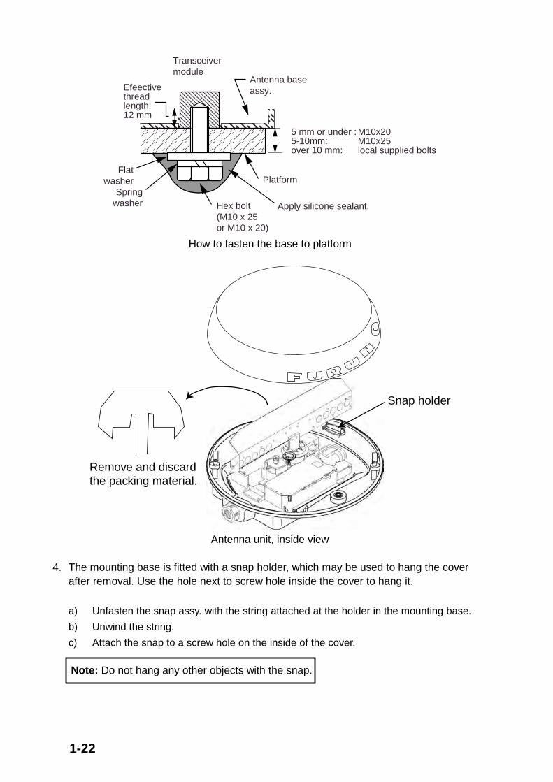
2. Construct a platform (wood, steel, or aluminum) of 5-10 mm (recommended dimension)in thickness referring to the outline drawing at back of this manual. A mounting bracketfor mounting the antenna unit on a sailboat mast is optionally available. (Refer to page1-26.) Fasten the platform to the mounting location. Next, position the base so the cableentrance faces the stern direction.
Note: When drilling holes in the platform, be sure they are parallel with the fore and aft line.
3. Using the hex bolts, flat washers and spring washers removed at step 1, fasten the baseto the platform. The torque should be between 19.6-24.5 N•m.
Note: Longer hex bolts (M10X25) are supplied with the installation materials. Use them instead of the hex bolts removed earlier if the mounting platform thickness is 5–10 mm.
1-22
Flatwasher
Antenna baseassy.
Springwasher
Platform
Hex bolt Apply silicone sealant.(M10 x 25or M10 x 20)
Transceivermodule
5 mm or under : M10x205-10mm: M10x25over 10 mm: local supplied bolts
Efeectivethreadlength:12 mm
How to fasten the base to platform
Remove and discard the packing material.
Snap holder
Antenna unit, inside view
4. The mounting base is fitted with a snap holder, which may be used to hang the coverafter removal. Use the hole next to screw hole inside the cover to hang it.
a) Unfasten the snap assy. with the string attached at the holder in the mounting base.
b) Unwind the string.
c) Attach the snap to a screw hole on the inside of the cover.
Note: Do not hang any other objects with the snap.

1-23
5. Unfasten the rotation detector cable from the cable clamps.6. Unfasten 16 screws (!1 , !2 and !3 in the following figure) to dismount the shield plate,
core case assy and core case cover.
GNDIF
+VOP
GND
-VOP
VtGND
Pan head screwsM3x10 2 pcs. 2
Shield plate
Pan head screwsM4x8 9 pcs.
Pan head screwsM4x10 5 pcs.
Core case cover
Core case
1
1
1
1
1 1
1
1
33
3
3
3
3
3
3
3
3
2
2
Cable clamps
11
Rotation detector cable
Caution: Be careful not to pinch the rotation detector cable when remounting the shield plate.

1-24
7. Pass the antenna cable with connector through the cable gland, gasket and cableentrance of the antenna unit, and then tighten cable gland.
Note 1: Be sure the shrink tube on the antenna cable does not contact to the gasket. Note 2: Close the gasket tightly to insert into the cable entrance. Confirm that there is no
space between both ends of the gasket after inserting into the cable entrance.
Rubber gasket
Gasket
Cable Gland
Sectional view
Mounting base
Rubber gasket
Antenna cable
Gasket
Close the gasket tightly.
Shrink tube
Do not contact the shrink tube and gasket.
Antenna unit, inside view
8. Twist antenna connector cables at the position between the shrink tube and the cable tie,and then attach EMI core (supplied) to cables as follows.After attachment, shift EMI core slightly to confirm that it does not pinch cables.
Cable tieShrink tube
Attach EMI core.
GasketRadome base
Twist cables here.
Location of EMI core

1-25
9. Attach connectors of the antenna cable as appropriate, and then fasten a pan headscrew M4x10 to fix shield cable and core case (removed at step 6.)
Antenna unit, connector location and fixing the shield cable w/core case 10.Put EMI core on antenna cable into the core case attached at step 9.
A flat side of core should be faced downward.
EMI core
Core case
EMI core, putting into core case 11.Refasten the shield plate and core case cover with 15 screws. Be sure that the cable
from the rotation detector passes through the notch between the two cable ties.
How to pass the rotation detector cable

1-26
12. Pass the cable from the rotation detector through two cable clamps.Rotate detector
Cable clamps
Cable tie(Another should
be inside.)
Antenna unit, clamping the rotation detector cable 13. Follow the instructions on the label inside the mounting base to secure the snap assy.14. Confirm that the rubber gasket is properly positioned and that the triangle mark on the
radome cover is aligned with the triangle mark on the mounting base, then tighten thefixing screws for the cover. Refer to the figure of sectional view on the previous page forpositioning of rubber gasket.
1.5.2 Mounting the optional mounting bracket A mounting bracket for fastening the antenna unit to a mast on a sailboat is optionally available.
Mounting bracket 2
Type: OP03-93 Code No.: 008-445-080
Type Code No. QtyHex. bolt M4x12 000-804-725 4 Hex. bolt M8x20 000-805-707 8 Mounting plate 03-018-9001-0 100-206-740 1 Support plate (1) 03-018-9005-0 100-206-780 1 Support plate (2) 03-018-9006-0 100-206-790 1 Bracket (1) 03-028-9101-0 100-206-810 1 Bracket (2) 03-028-9102-0 100-206-820 1 Fixing plate 03-028-9103-0 100-206-830 2
Assemble the mounting bracket and fasten it to a mast. Fasten the antenna unit to the bracket. For detail, see the figure shown on page 1-10.

2-1
2. WIRING2.1 Standard Wiring All wiring are terminated at the rear of the display unit.
NavNetequipment,CU-200(6P)
CAUTIONThe display unit is shipped with 15 A fuse.Replace fuse with 7A when using the equipment in the following condition;MODEL1823C/1833C/1933C/1943C: ship's battery is 24 VDCMODEL1953C/GD-1900C: ship's battery is 12/24 VDC
Also, attach a label to the fuse cover on power cable. Use of wrong fuse can result in damage to the equipment.
12-24 VDCConnect powercable here.
Ground terminalConnect ground wire betweenhere and ship's ground.
Drain hole(Allows moisture
to escape.)
OPTION(remote display VGA monitor)
DATA1DATA2DATA3
GPS receiverGPS-310B/320Bor NMEA (7P)
NMEA (6P)Headingsensor(AD or NMEA format) (6P)
DATA4NETWORK
Ext. buzzer/PC/NMEA IN (Echo sounder) (7P)
Ground theequipment toprevent interference.
CAUTION
MODEL1823C/1833C/1933C/1943C:To antenna unit
MJ-B24LPF0009-050cable
Signal cable MJ-B24LPF0005.
MODEL1953C:To antenna unit
12-24 VDCUse the power source which powers the display unit.
Power supply unitPSU-005(MODEL 1953C only)
Display unit, rear view

2-2
12-24 VDC Connect the power cable to the POWER connector at the back of the display unit.
DJ-1 For MODEL1823C/1833C/1933C/1943C/1953C, remove the waterproofing cap from DJ-1 port and discard it.
MODEL1823C/1833C: Connect the MJ-B24LPF0002 cable from the antenna unit to this port.
MODEL1933C/1943C/1953C: Connect the MJ-B24LPF0005 cable from the power supply unit to this port.
GD-1900C: Do not remove the waterproofing cap. Wrap the connector nut and cap with vinyl tape as shown below.
Connector nut (for 24P)
Waterproofing cap (yellow)
Vinyl tape
Waterproofing cap and connector nut, sectional view Ground terminal Connect the ground wire (local supply, IV-2sq) between the ground terminal and ship’s ground.
DATA1 to DATA4 Other equipments can be connected here as shown below.
DATA1 (7P) DATA2 (6P) DATA3 (6P) DATA4 (7P) GPS receiver GP-310B/320B
NMEA sentence (ex. Navaid)
Heading sensor (ex. SC-60/120) (MODEL series only)
External buzzer, PC, NMEA IN (Echo sounder)
This equipment can receive the following NMEA 0183 format sentence from other equipments. • Own ship’s position: GGA>RMC>RMA>GLL Time: ZDA
• Ship’s speed: RMC>RMA>VTG>VHW Other ship’s information: TTM
Insight satellite information: GSV Wind speed and angle:
• Heading (True): HDT>HDG>HDM MWV>VWT/VWR
• Course: RMC>RMA>VTG
• Depth: DPT>DBT
• Temperature: MTW You will need the optional NMEA cable to connect with other equipments (E/S, navaid, etc.).
2-3
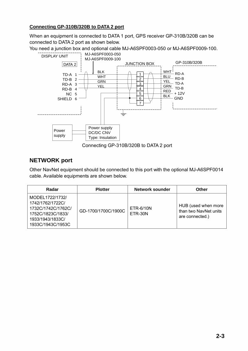
Connecting GP-310B/320B to DATA 2 port
When an equipment is connected to DATA 1 port, GPS receiver GP-310B/320B can be connected to DATA 2 port as shown below. You need a junction box and optional cable MJ-A6SPF0003-050 or MJ-A6SPF0009-100.
1234567
JUNCTION BOX
123456
TD-ATD-BRD-ARD-B
NCSHIELD
DISPLAY UNIT
DATA 2
+ 12VGND
WHTBLUYELGRNREDBLK
GP-310B/320B
BLKWHTGRNYEL
MJ-A6SPF0003-050MJ-A6SPF0009-100
Power supplyDC/DC CNVType: Insulation
Powersupply
RD-ARD-BTD-ATD-B
Connecting GP-310B/320B to DATA 2 port
NETWORK port Other NavNet equipment should be connected to this port with the optional MJ-A6SPF0014 cable. Available equipments are shown below.
Radar Plotter Network sounder Other
MODEL1722/1732/ 1742/1762/1722C/ 1732C/1742C/1762C/ 1752C/1823C/1833/ 1933/1943/1833C/ 1933C/1943C/1953C
GD-1700/1700C/1900C ETR-6/10N ETR-30N
HUB (used when more than two NavNet units are connected.)

2-4
2.2 External Buzzer (OP03-136, option) Connection The optional external buzzer provides a louder alert when the alarm is viorated.
External buzzer Type: OP03-136 Code no.: 000-086-443
Further, you need the optional cable assy MJ-A7SPF0007-050 (w/7P connector, 5 m, code no. 000-144-418).
1. Attach the MJ-A7SPF0007-050 cable assy (option) to the DATA 4 port at the rear of thedisplay unit.
2. Cut the XH connector at the end of the external buzzer cable with appropriate length.3. Solder the cables made at step 2 with MJ-A7SPF0007-050 cable as shown below.
Red
BlackExternal buzzer MJ-A7SPF0007-050
Soldering
Other cable should be cut off, and wrap here with tape.
Connection of external buzzer and display unit using cable assy type MJ-A7SPF0007-050 cable
4. Fasten the buzzer with the double-sided tape or two tapping screws (3x15 or 3x20, localsupply).

2-5
2.3 How to Connect with PC When connecting with the personal computer, prepare the optional cable assy MJ-A7SPF0007-050 and D-sub 9 pins plug (local supply), and connect them as follows.
SHIELD
BLUE
D-SUB 9PIN
MJ-A7SPF0007-050
15
69
WHITEBLUE
CDRDTD
DTRGNDDSRRTSCTS
RI
123456789
TD_DTRD_DTRD3_ARD3_B+12VEXT BUZZGND
1234567
SHIELD
short
WHITE
DATA4
MJ-A7SPF0007-050 cable connection for PC

2-6
2.4 Wiring of Power Supply Unit (MODEL1953C only) 1. Loosen three M4 screws to remove the cable clamp.2. Loosen six M4 screws to remove the unit cover.3. Attach the VL connector of power supply cable VL3P-VV-S2X2C-AA050 (supplied as
installation material) to J1 on the POWER Board.4. Attach the VH and NH connectors of MJ-B24LPF0009-050 cable (supplied as
installation material) to the locations appropriately; VH9: J3, VH4: J4, NH13: J5.
VL-3
VL3P-VV-S2X2C-AA050cable(to ship's mains)
MJ-B24 LPF0009-050 cable(to display unit)
Slot(large)
Slot(small)
POWER Board19P1006
ANT (J8)
Signal cable(to antenna unit)
J1
Ground terminal(Wing bolt)
VH9
NH13
VH4
J3
J4J5
Shield
Cable tie(if necessary)
Power supply unit, cover removed
5. Lay two cables on the slots referring the figure in the above.When MJ-B24LPF0009-050 cable has a tension, fasten the cable tie (local supply) to theposition shown above to avoid pulling the cable off.
6. Reattach the unit cover (removed at step 2).7. Reattach the cable clamp (removed at step 1) to fix two cables.8. Connect the signal cable to ANT port on the power supply unit.9. Connect the ground wire (local supply, IV-2sq) between the ground terminal and ship’s
ground.

2-7
Note: The power for the power supply unit and display unit must be drawn from the same power switch on the power terminal board.
Other Equipment(ex. GPS, E/S etc.)
Power terminal board
Display unit Power supply unit
Other Equipment(ex. GPS, E/S etc.)
Other Equipment(ex. GPS, E/S etc.)
Other Equipment(ex. GPS, E/S etc.)
Other Equipment(ex. GPS, E/S etc.)
CAUTIONThe display unit and antenna should be powered from the same power source.This should be done so the antenna will rotate only when the display unit is turned on.
Replacement of the fuse The power supply unit is shipped with 15 A fuse. Replace fuse with 7 A (supplied) when the ship’s battery is 24 VDC. Note that replace fuse of the display unit with 7 A when the ship’s battery is 24 VDC.

2-8
2.5 Connection of CU-200 (option) 1) Connection between one display unit and one memory card IF unit
Connect as shown in the figure below.
Display unit Memory card IF unitCU-200
NETWORK
12 VDC
NETWORK
MJ-A15A3F0003-030 (3 m, supplied)
MJ-A6SPF/TM11AP8-C050 (5 m,supplied)
two mini-cards
12 VDC
2) Connection between one memory card IF unit and multiple processor unitsPrepare optional cable MJ-A6SPF0014-010/050/100/200/300 (1, 5, 10, 20 or 30 m) andMJ-A6SRM-D/TM 11AP8-005. Also, procure HUB and CAT5 STP cable locally. Connect asshown in the figure below.
No.1Display unit
NETWORK
No.2Display unit
No.3Display unit
No.4Display unit
MJ-A15A3F0003-030 (3 m, supplied)
Memory card IF unit
12 VDC
NETWORK
MJ-A6SPF0014-010/050/100/200/300 (cross)
CAT5 STP cable (local supply) HUB
(owner supply)
two mini-cards
MJ-A6SRMD/TM11AP8-005
MJ-A6SPF0014-010/050/100/200/300
MJ-A6SPF0014-010/050/100/200/300
MJ-A6SPF0014-010/050/100/200/300
12 VDC

3-1
3. ADJUSTMENT3.1 How to Access to Installation Menu You should do the set up for the equipment through the installation menu when installation has been finished. To access to the installation menu, follow the steps in below.
1. With the display powered off, hold down the [MENU] key. Then, momentarily press the[POWER/TX] key while continuing to hold the [MENU] key down. You may release the[MENU] key when a blue start-up screen appears.
2. Release the [MENU] key when the message of “STARTING INSTALLATION MODE”appears.
3. After the radar screen appears, press the [MENU] key to show the RADAR MENU.4. Press the SYSTEM CONFIGURATION soft key to show the SYSTEM CONFIG menu.
SYSTEMCONFIG
GENERAL SETUP
NAV OPTION
SYSTEM SETUP
INSTALLATION SETUP
RETURN
Radar menu (Ex. MODEL1833C/1933C/1943C/1953C)
System configuration menu
RADAR MENU
RADAR DISPLAY SETUP
RADAR RANGE SETUP
ARP SETUP
FUNCTION KEY SETUP
SYSTEM CONFIGURATION
How to access the Installation menu
5. Press the INSTALLATION SETUP soft key to display the INSTALL SETUP menu.INSTALL SETUP
NETWORK SETUP
RADAR SETUP
NETWORK SOUNDER SETUP*
RETURN
*: Do not change this item setting.
Installation setup menu
3-2
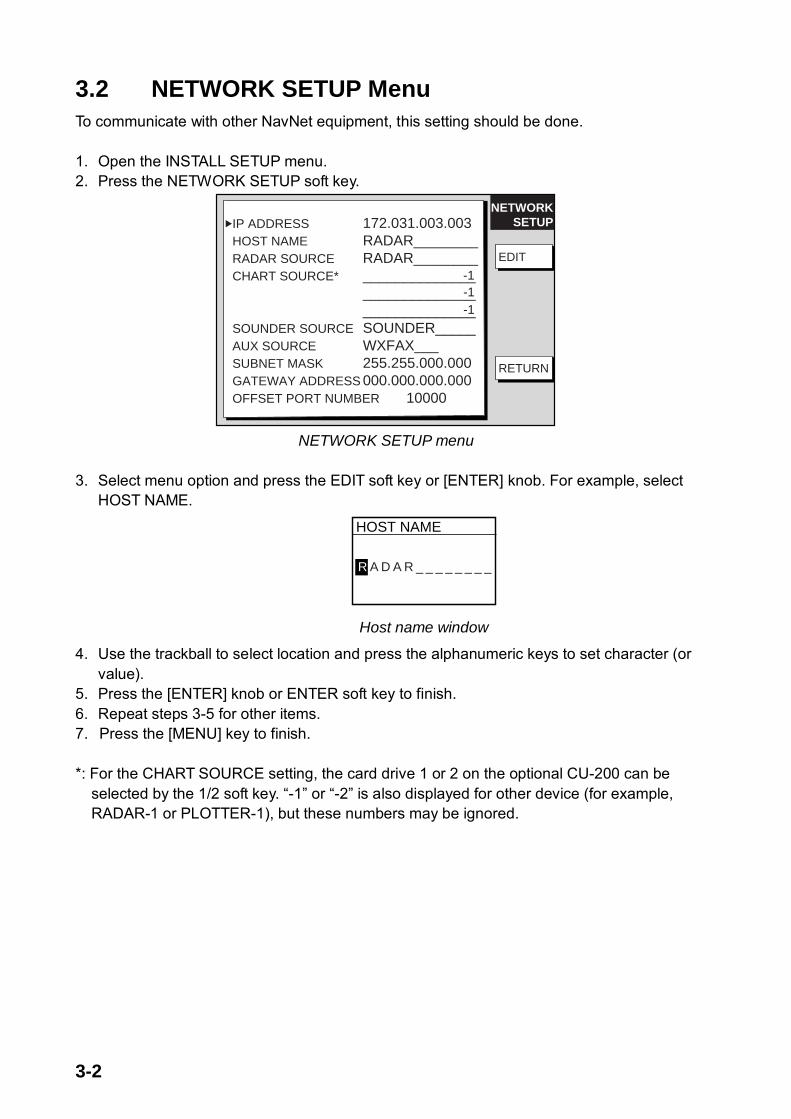
3.2 NETWORK SETUP Menu To communicate with other NavNet equipment, this setting should be done.
1. Open the INSTALL SETUP menu.2. Press the NETWORK SETUP soft key.
EDIT
RETURN
IP ADDRESS 172.031.003.003HOST NAME RADAR________RADAR SOURCE RADAR________CHART SOURCE* ______________
____________________________
SOUNDER SOURCE SOUNDER_____AUX SOURCE WXFAX___SUBNET MASK 255.255.000.000GATEWAY ADDRESS 000.000.000.000OFFSET PORT NUMBER 10000
NETWORKSETUP
EDIT
-1-1-1
NETWORK SETUP menu
3. Select menu option and press the EDIT soft key or [ENTER] knob. For example, selectHOST NAME.
HOST NAME
R A D A R _ _ _ _ _ _ _ _
Host name window
4. Use the trackball to select location and press the alphanumeric keys to set character (orvalue).
5. Press the [ENTER] knob or ENTER soft key to finish.6. Repeat steps 3-5 for other items.7. Press the [MENU] key to finish.
*: For the CHART SOURCE setting, the card drive 1 or 2 on the optional CU-200 can be selected by the 1/2 soft key. “-1” or “-2” is also displayed for other device (for example, RADAR-1 or PLOTTER-1), but these numbers may be ignored.

3-3
Contents of Network setup menu
Item Description Default Setting
IP ADDRESS This address is assigned at the factory. Change the address (last three digits; 001 to 254) when like models are connected directly or through the hub. Do this change before connecting the equipment to the other equipment or hub to distinguish. Do not set the same IP address in the network.
Radar: 172.031.003.003
MODEL series: RADAR
HOST NAME Set the name for your display unit to distinguish it from others in the NavNet system. Confirm that two equipment don’t have same host names. The host name has been preset depending on the series of NavNet. See the table in below. This host name is used for RADAR SOURCE and CHART SOURCE.
GD-1900C: PLOTTER
RADAR SOURCE Enter the host name “RADAR (preset)” or the new name set at HOST NAME item setting if the unit has been changed of the network radar to use for the radar display. Clear the RADAR SOURCE name when your equipment is GD-1900C and no radar is connected.
RADAR
CHART SOURCE Enter a host name (set at HOST NAME) of network display unit to select equipment which has chart card in its slot (Max. three units) to use. The driver names of the memory card interface unit (option) are MCDRIVE-1 (left side) and MCDRIVE-2 (right side).
None
SOUNDER SOURCE The host name of the network sounder ETR-6/10N or ETR-30N is preset (SOUNDER) to use for the video sounder display. Clear the host name when no network sounder is connected.
SOUNDER
AUX SOURCE For the facsimile receiver FAX-30. Use the default setting. WX FAX
SUBNET MASK 255.255.000.000
GATEWAY ADDRESS 000.000.000.000
OFFSET PORT NUMBER
Not used. Reserved for future use.
10000
NavNet equipment default settings
Model IP ADDRESS HOST NAME
MODEL1722/1732/1742/1762 172.031.003.004 RADAR
MODEL1722C/1732C/1742C/1762C/1752C 172.031.003.001 RADAR
MODEL1833/1933/1943 172.031.003.002 RADAR
MODEL1823C/1833C/1933C/1943C/1953C 172.031.003.003 RADAR
GD-1700/1700C 172.031.014.001 PLOTTER
GD-1900C 172.031.003.003 PLOTTER
CU-200 172.031.014.100 MCDRIVE

3-4
3.3 RADAR SETUP Menu After the network setup, do the following in order to adjust the radar. Open the INSTALL SETUP menu, and then press the RADAR SETUP soft key to display the RADAR SETUP menu. When the message of “RADAR DOES NOT TRANSMIT. TRANSMIT RADAR?” appears, press the [ENTER] knob to transmit or [CLEAR] key to cancel transmitting.
RADAR SETUPHEADING ADJUST OFF
TOTAL ON TIME 000000.0 hTOTAL TX TIME 000000.0 h
Page 2
Page 1
EDIT
EDIT
ANTENNA TYPE FHEADING DATA MAGNETICANTENNA ROTATION ROTATE*TUNING OFFTIMING ADJUST OFFVIDEO ADJUST OFFM.B. SUPPRESSION OFFRADAR ANTENNA HEIGHT HIGHSTC CURVE NARROWMONITOR MODE OFF
RADAR SETUP
NEXT PAGE
RETURN
*: Do not change this item setting (excluding 1953C).
PREV. PAGE
Radar setup menu

3-5
3.3.1 ANTENNA TYPE Select the antenna type connecting with your display unit. Default setting is “F”. Select the antenna type referring to the table shown below. After selection, press the [ENTER] knob or ENTER soft key.
Your unit Setting MODEL1823C A
MODEL1833C B
MODEL1933C F
MODEL1943C G
MODEL1953C H
3.3.2 TUNING MODEL 1953C: Go to “Tuning for 1953C power supply unit”, and then “Antenna tuning” Other models: Go to “Antenna tuning”.
Tuning for 1953C power supply unit
For MODEL 1953C, first of all tune the power supply unit to adjust the point of tuning indicator.
1. Open the power supply unit cover.2. On the RADAR SETUP menu, select STOP at ANTENNA ROTATION.3. Close the menu, and then transmit the radar with the range more than 6 nm.4. Flip the SW1 on the POWER Board to upward (for tuning position).5. Adjust R36 potentiometer clockwise so that CR13 LED lights in the highest brilliance.
Also adjust R36 so that the voltage becomes the largest by using a multimeter. (TP5: +, TP2: -)6. Flip the SW1 to downward (normal position, default setting).7. Reassemble the power supply unit.8. Go to the “Antenna tuning” on the next page.
R36
POWER Board19P1006
CR13
SW1
TP5
Upword
Downward
TP2
Power supply unit, cover removed

3-6
Antenna tuning
Initialize the tuning as follows.
1. Transmit the radar.2. Open the RADAR SETUP menu, and then select TUNING by the trackball or [ENTER]
knob.3. Press the EDIT soft key or [ENTER] knob to show the setting window.
TUNING
ONOFF
Tuning setup menu
4. Select ON.5. Press the [ENTER] knob or ENTER soft key to start the auto tuning.6. After the adjustment is completed, the message of “NOW TUNING” disappears.7. Return to the menu display automatically.
3.3.3 TIMING ADJUST
This adjustment ensures proper radar performance, especially on short ranges. The radar measures the time required for a transmitted echo to travel to the target and return to the source. The received echo appears on the display based on this time. Thus, at the instant the transmitter is fired, the sweep should start from the center of the display (sometimes called sweep origin.)
A trigger pulse generated in the display unit goes to the antenna unit through the signal cable to trigger the transmitter (magnetron). The time taken by the signal to travel up to the antenna unit varies, depending largely on the length of signal cable. During this period the display unit should wait before starting the sweep. When the display unit is not adjusted correctly, the echoes from a straight local object (for example, a harbor wall or straight pier) will not appear with straight edges – namely, they will be seen as “pushed out” or “pulled in” near the picture center. The range of objects will also be incorrectly shown.
(2) Correct(1) Target pulled
(3) Target pushed outward
Examples of improper and correct sweep timing 1. Transmit on the shortest range and confirm that gain and A/C SEA are properly
adjusted.2. Visually select a target which forms straight line (harbor wall, straight piers).3. Open the RADAR SETUP menu and select TIMING ADJUST.4. Press the EDIT key or [ENTER] key to show the setting window.

3-7
ONOFF
TIMING ADJUST
Timing adjust setting menu 5. Select ON and press the [ENTER] knob or ENTER soft key to show the radar display.
PUSH ENTER KNOB AFTERADJUSTING SWEEP TIMING.
RETURN
Timing adjustment setting display 6. Rotate the [ENTER] knob to straighten the target selected at step 2, and then press the
RETURN soft key to finish.
3.3.4 VIDEO ADJUSTMENT
Adjusts video amplifier input level.
1. Open the RADAR SETUP menu and select VIDEO ADJUST by the trackball or [ENTER]knob.
2. Press the EDIT soft key or [ENTER] knob to show the setting window.
ONOFF
VIDEO ADJUST
Video adjustment setting window 3. Select ON.4. Press the [ENTER] key or ENTER soft key to start video adjustment.5. When adjustment is completed, the message of “NOW ADJUSTING VIDEO” disappears,
and return to the menu display automatically.

3-8
3.3.5 HEADING ADJUST
You have mounted the antenna unit facing straight ahead in the direction of the bow. Therefore, a small but conspicuous target dead ahead visually should appear on the heading line (zero degrees).
In practice, you will probably observe some small error on the display because of the difficulty in achieving accurate initial positioning of the antenna unit. The following adjustment will compensate for this error.
1. Set ship’s heading toward a suitable target (for example, ship or buoy) at a rangebetween 0.125 and 0.25 nautical mile.
2. Open the RADAR SETUP menu, and press the NEXT PAGE soft key.3. Select HEADING ADJUST and press the EDIT soft key or [ENTER] knob to show the
HEADING ADJUST window.4. Select ON followed by [ENTER] key or ENTER soft key to show the radar display.
SET
RETURN
PUSH SOFTKEY 'SET' AFTERADJUSTING HEADING LINE.
Heading adjustment setting display 5. Rotate the [ENTER] knob to bisect the target with the EBL.6. Press the SET soft key.7. As a final test, move the boat towards a small buoy and confirm that the buoy shows up
dead ahead on the radar when it is visually dead ahead.
3-9
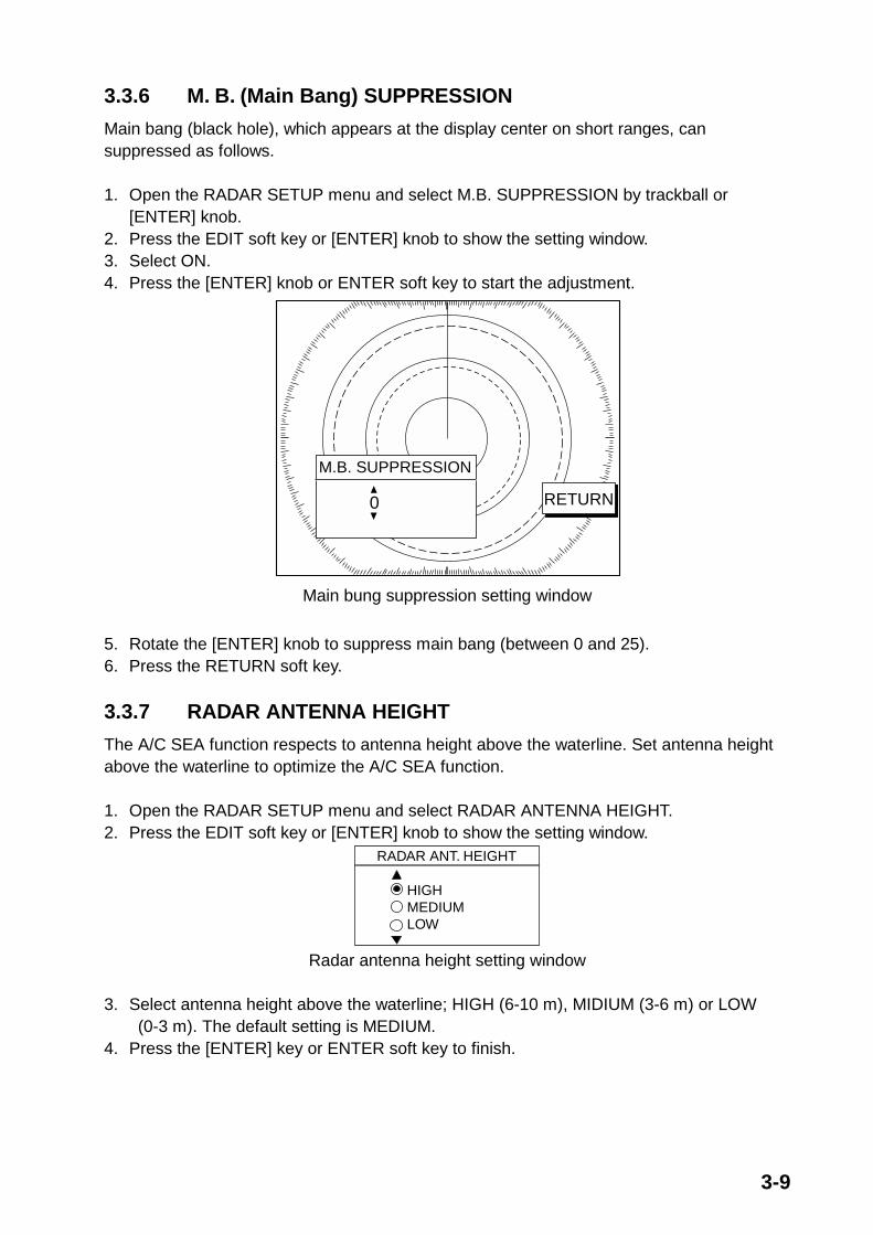
3.3.6 M. B. (Main Bang) SUPPRESSION
Main bang (black hole), which appears at the display center on short ranges, can suppressed as follows.
1. Open the RADAR SETUP menu and select M.B. SUPPRESSION by trackball or[ENTER] knob.
2. Press the EDIT soft key or [ENTER] knob to show the setting window.3. Select ON.4. Press the [ENTER] knob or ENTER soft key to start the adjustment.
RETURN
M.B. SUPPRESSION
0
Main bung suppression setting window
5. Rotate the [ENTER] knob to suppress main bang (between 0 and 25).6. Press the RETURN soft key.
3.3.7 RADAR ANTENNA HEIGHT
The A/C SEA function respects to antenna height above the waterline. Set antenna height above the waterline to optimize the A/C SEA function.
1. Open the RADAR SETUP menu and select RADAR ANTENNA HEIGHT.2. Press the EDIT soft key or [ENTER] knob to show the setting window.
HIGHMEDIUMLOW
RADAR ANT. HEIGHT
Radar antenna height setting window
3. Select antenna height above the waterline; HIGH (6-10 m), MIDIUM (3-6 m) or LOW(0-3 m). The default setting is MEDIUM.
4. Press the [ENTER] key or ENTER soft key to finish.

3-10
3.3.8 STC CURVE
The default STC curve can be maintained in most cases. If necessary the STC curve can be changed as follows:
1. Open the RADAR SETUP menu and select STC CURVE.2. Press the EDIT soft key or [ENTER] knob to show the setting window.
RETURNNARROWNORMALWIDE
STC CURVE
STC curve setting window
3. Select STC curve;NARROW: The effective range of the [A/C SEA] adjustment is relatively short.NORMAL: Between NARROW and WIDE.WIDE: The effective range of the [A/C SEA] adjustment is relatively long.
4. Press the RETURN soft key to finish.
3.3.9 HEADING DATA
Select the heading reference, MAGNETIC or TRUE. Select MAGNETIC when connecting with the magnetic compass, select TRUE when connecting with the true compass. For your reference, when connecting with Satellite Compass SC-60/120 or Integrated Hading Sensor PG-1000 which Furuno makes, set the heading data as the table shown below.
Model Setting of HEADING DATA with L/L data TRUE
PG-1000 w/o L/L data MAGNETIC
SC-60/120 TRUE
1. Open the RADAR SETUP menu and then select HEADING DATA.2. Press the EDIT soft key or [ENTER] knob to show the setting window.
HEADING DATA
MAGNETICTRUE
Heading data setting window 3. Select MAGNETIC or TRUE.4. Press the [ENTER] knob or ENTER soft key.
3-11
3.4 Checking Magnetron Heater Voltage Note: This confirmation/adjustment should only be performed by a qualified service
technician.
Magnetron heater voltage is formed on the PTU (1833C)/MD (1823C/1933C/1943C/1953C) Board of the antenna unit, and preadjusted at the factory. Therefore no adjustment is required. However, check magnetron heater voltage for confirmation as follows:
1. Open the antenna unit.2. Turn on the power. Do not transmit the radar.3. Connect a multimeter, set to 10VDC range, appropriate position on the MD (1823C),
PTU (1833C) or RTB (1933C/1943C1953C) Board in the antenna unit. Refer to the tablein below.
4. Confirm that the multimeter indication is appropriately.
MODEL1823C MODEL1833C MODEL1933C/1943C/1953C
Check point TP804#6 (+) and #4 (-) on MD Board
TP802#4 (+) and #6 (-) on PTU Board
J825#4 and #6 (GND) on RTB Board
Multimeter indication 7.9 to 8.1 V 7.4 to 7.6 V 7.4 to 7.6 V
Adjustment point VR801 on MD Board R106 on PTU Board VR801 on MD Board
3.5 Navigation Data Source The NAV SOURCE SETTINGS menu mainly selects the source of nav data. For navigator other than the FURUNO GP-310B/320B, speed averaging and local time offset (to use local time instead of UTC time) are also available from this menu.
1. Press the [MENU] key followed by SYSTEM CONFIGURATION, NAV OPTION and NAVSOURCE SETTINGS soft keys to show the NAV SETUP menu.
NAVSETUPPOSITION SOURCE ALL
SPEED AVERAGING* 0060second (s)LOCAL TIME OFFSET* +00:00TEMP CALIBRATION +00 FDEPTH CALIBRATION +00ft
* For GPS receiver other than GP-310B/320B.
RETURN
EDIT
Nav setup menu

3-12
2. Select POSITION SOURCE and press the [EDIT] key or [ENTER] knob to show theposition source window.
POSITION SOURCE¡
¡
¡
¤
FURUNO BB GPSGPLCALL
3. Select FURUNO BB GPS, GP, LC or ALL as appropriate and press the [ENTER] knobor ENTER soft key.FURUNO BB GPS: GPS Receiver GP-310B/320BGP: GPS navigator (via NETWORK or DATA 1, DATA2 connector)LC: Loran C (via NETWORK or DATA 1, DATA 2 connector)ALL: Multiple navaid connection (via NETWORK or DATA 1, DATA 2 connector)
4. For GPS receiver other than the GP-310B/320B, you may adjust speed averaging anduse local time.a) Choose desired item and press the EDIT soft key.b) Use the trackball to select location and rotate the [ENTER] knob to set value. For time, use
the +< - -> - soft key to switch from plus to minus and vice versa.c) Press the [ENTER] key.
Speed Averaging: Calculation of ETA is based on average ship’s speed over a given period. If the period is too long or too short calculation error will result. Change this setting if calculation error occurs. The default setting, 60 seconds, is suitable for most conditions. The range of adjustment is 0-9999 (sec). Local Time Offset: GPS uses UTC time. If you would rather use local time enter the time difference between it and UTC. The range of offset is –13:30 to + 13:30 and the default setting is zero (no offset). This setting is not necessary if the difference time is entered at the GPS navaid which is connected. Temp Calibration: Offsets NMEA water temperature data (-40ºF to +40ºF). Depth Calibration: Offsets NMEA depth data (-15 ft to +90 ft).
5. For GP-310B/320B, press the RETURN soft key twice to show SYSTEM CONFIGmenu.
6. Press the SYSTEM SETUP soft key followed by PORT SETUP and GPS/NMEA PORTsoft keys. When the GP-310B/320B is connected to the DATA 2 port, press the NMEAPORT soft key.
7. Select FURUNO GPS SENSOR, and press the [ENTER] knob or EDIT soft key to showFURUNO GPS SENSOR window.
8. Select YES and press the [ENTER] knob or ENTER soft key.9. Press the RETURN soft key three times followed by NAV OPTIONS, GPS SENSOR
SETTINGS soft keys to show the GPS SETUP menu.
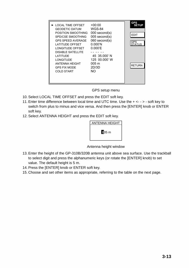
3-13
GPSSETUPLOCAL TIME OFFSET +00:00
GEODETIC DATUM WGS-84POSITION SMOOTHING 000 second(s)SPD/CSE SMOOTHING 005 second(s)GPS SPEED AVERAGE 060 second(s)LATITUDE OFFSET 0.000’NLONGITUDE OFFSET 0.000’EDISABLE SATELLITE - - - - - -LATITUDE 45 35.000’ NLONGITUDE 125 00.000’ WANTENNA HEIGHT 005 mGPS FIX MODE 2D/3DCOLD START NO
EDIT
GPSSTATUS
RETURN
GPS setup menu
10. Select LOCAL TIME OFFSET and press the EDIT soft key.11. Enter time difference between local time and UTC time. Use the + <- - > - soft key to
switch from plus to minus and vice versa. And then press the [ENTER] knob or ENTERsoft key.
12. Select ANTENNA HEIGHT and press the EDIT soft key.
ANTENNA HEIGHT
005 m
Antenna height window
13. Enter the height of the GP-310B/320B antenna unit above sea surface. Use the trackballto select digit and press the alphanumeric keys (or rotate the [ENTER] knob) to setvalue. The default height is 5 m.
14. Press the [ENTER] knob or ENTER soft key.15. Choose and set other items as appropriate, referring to the table on the next page.

3-14
Contents of GPS sensor settings menu
Item Description Settings Default SettingLocal Time Offset Allows the user to use local time (instead
of UTC time). Enter time difference between local time and UTC time. Use the + < - - > - soft key to switch from plus to minus and vice versa.
-13:30 to +13:30 hr 0 hr (no offset)
Geodetic Datum Your equipment is preprogrammed with most of the major chart systems of the world. Although the WGS-84 system, the GPS standard, is now widely used other categories of charts still exist. Select the chart system used, not the area where your boat is sailing.
Use the trackball or [ENTER] knob to select appropriate chart.
WGS-84
Position Smoothing When the DOP or receiving condition is unfavorable, the GPS fix may change, even if the vessel is dead in water. This change can be reduced by smoothing the raw GPS fixes. A setting between 000 to 999 is available. The higher setting the more smoothed the raw data, however too high a setting shows response time to change in latitude and longitude. This is especially noticeable at high ship’ speeds. Increase the setting if the GPS fix changes.
0-999 sec 0 sec (no position smoothing)
Spd/Cse Smoothing
During position fixing, ship’s velocity (speed and course) is directly measured by receiving GPS satellite signals. The raw velocity data may change randomly depending on receiving conditions and other factors. You can reduce this random variation by increasing the smoothing. Like with latitude and longitude smoothing, the higher the speed and course smoothing the more smoothed the raw data. If the setting is too high, however, the response to speed and course change slows. For no smoothing, enter all zeros.
0-999 sec 5 sec
GPS Speed Average
Calculation of ETA is based on average ship’s speed over a given period. If the period is too long or too short calculation error will result. Change this setting if calculation error occurs. The default setting is 60 seconds, which is suitable for most conditions.
0-999 sec 60 sec
Latitude Offset Offsets latitude position to further refine position accuracy. Use the N <- - > S soft key to switch coordinate.
9.999’S – 9.999’N 0.0’ (no offset)
(Continued on next page)

3-15
Contents of GPS sensor settings menu (con’t.)
Item Description Settings Default SettingLongitude Offset As above but for longitude. Use the W < -
- > E soft key to switch coordinate. 9.999’E – 9.999’W 0.0’ (no offset)
Disable Satellite Every GPS satellite is broadcasting abnormal satellite number (s) in its Almanac, which contains general orbital data about all GPS satellites, including those which are malfunctioning. Using this information, the GPS receiver automatically eliminates any malfunctioning satellite from the GPS satellite schedule. However, the Almanac sometimes may not contain this information. If you hear about a malfunctioning satellite from another source, you can disable it manually. Enter satellite number (max. 3 satellites) in two digits and press the ENTER soft key.
None
Latitude Set initial latitude position after cold start. Use the N < - -> S soft key to switch coordinate.
90°S - 90°N 45°35.000’N
Longitude Set initial longitude position after cold start. Use the W <- - > E soft key to switch coordinate.
180°E – 180°W 125°00.000W
Fix Mode Choose position fixing method: 2D (three satellites in view), 2D/3D (three or four satellites in view whichever is greater).
2D, 2D/3D 2D/3D
Antenna Height Enter the height of the GPS antenna unit above sea surface.
0-99 m 5 m
Cold Start Clears the Almanac to receive the latest Almanac.
No, Yes No
GPS STATUS (soft key)
Displays GPS satellite status display.

3-16
3.6 Setting up Data Ports Setup the data ports according to the equipment connected to them as follows.
1. Press the [MENU] key to open the menu.2. Press the SYSTEM CONFIGURATION, SYSTEM SETUP and PORT SETUP soft keys.3. Press the GPS/NMEA PORT for DATA 1 port, NMEA PORT for DATA 2 port, PC/NMEA
EXT, BUZZ PORT for DATA 4 port soft key as appropriate. One of the following displaysappears depending on your selection.
GPS/ PORT
EDIT
FURUNO GPS SENSOR YESOUTPUT FORMAT NMEA0183
Ver 2.0LAT/LON FORMAT DD˚ MM.MMM'OUTPUT DESTINATION NO
WIRING INFORMATIONTD-A>1>---WHITETD-B>2>---BLUERD-A>3>---YELLOWRD-B>4>---GREEN+12V>5>---REDGND >6>---BLACKFG >7>---SHIELD
DATA 1 port
WIRING INFORMATIONTxD >1>---WHITERxD >2>---BLUERD-A >3>---YELLOWRD-B >4>---GREEN+12V >5>---REDEXT BUZZ>6>---BLACKGND >7>---SHIELD
NMEA OUTPUT FORMAT NMEA VER. 2.0BAUD RATE 4800bpsBIT LENGTH 8 bitsSTOP BIT 1 bitPARITY NONE
(CONTROL: Xon/Xoff)
DATA 4 port
SELECTSNTNC
RETURN
WIRING INFORMATIONTD-A>1>---WHITETD-B>2>---BLACKRD-A>3>---YELLOWRD-B>4>---GREENNC >5>FG >6>---SHIELD
FURUNO GPS SENSOR NOOUTPUT FORMAT NMEA0183
Ver 2.0LAT/LON FORMAT DD˚ MM.MMM'OUTPUT DESTINATION NO
DATA 2 port
NMEA PORT
EDIT
SELECTSNTNC
RETURN
NMEA PORT
EDIT
SELECTSNTNC
RETURN
DATA1, DATA2, DATA 4 PORT menus
4. Select item and press the EDIT soft key.5. Set option referring to the tables on pages 3-17 and 3-18.6. To select NMEA data sentences to output, press the SELECT SNTNC soft key.
For NETWORK port, select the sentence to output to the network equipment (default: allOFF).

3-17
NMEA Version 2.0Range and bearing mode: Rhumb line
NMEA Version 1.5 Range and bearing mode: Great circle
SELECTSNTNC
RETURN
ON/OFF
AAMAPBBODBWRDPTGGAGLLGTDMTWRMARMBRMCVHWVTGWPLXTEZDAHDTHDGMWVTTM
--ON--------
ON------
ONON--
ON----
ON--------
AAMAPBBODBWCDBTGGAGLLGTDMTWRMARMBRMCVHWVTGWPLXTEZDAHDTHDGMWVTTM
--ON--------
ON------
ONON--
ON----
ON--------
SELECTSNTNC
ON/OFF
RETURN
NMEA data sentences
7. Select sentence and press the ON/OFF soft key to show ON (output) or “- -“ (no output)as appropriate.
8. Press the RETURN soft key.9. Press the [MENU] key to quit.
Contents of DATA 1 and DATA2 PORT menus
Item Description Settings Default SettingFURUNO GPS Sensor
Selects whether the GPS Receiver GP-310B/320B is connected to the DATA1 or DATA2 port or not.
Yes, No Yes (DATA1) No (DATA2)
Output Format Selects NMEA output version for the equipment connected.
NMEA0183 Ver. 1.5, NMEA0183 Ver. 2.0
NMEA0183 Ver. 2.0
Lat/Lon Format Selects latitude/longitude format to output.
DD°MM.MM’, DD°MM.MMM, DD°MM.MMMM’
DD°MM.MMM’
Output Destination Selects whether to output route (data sentence RTE) and waypoint data (data sentence WPL) when destination is set.
Yes, No No
SELECT SNTNC (soft key)
Selects data sentence(s) to output. Select sentence with the trackball and press the ON/OFF soft key to show ON or “- -“ (OFF) as appropriate. See the figure above for sentence and default settings.
3-18
Contents of DATA 4 PORT menu
Item Description Settings Default SettingNMEA Output Format
Selects NMEA output format. NMEA Ver. 1.5, NMEA Ver. 2.0
NMEA Ver. 2.0
Baud Rate Sets baud rate. 4800, 9600, 19200 (bps) 4800(bps) Bit Length Sets character length. 8 bit, 7 bit 8 bit Stop Bit Sets number of stop bits. 1 bit, 2 bit 1 bit Parity Sets parity bit. Even, Odd, None Even SELECT SNTNC (soft key)
Chooses data sentences to output. For further details see the illustration “NMEA data sentences” on page 3-17.
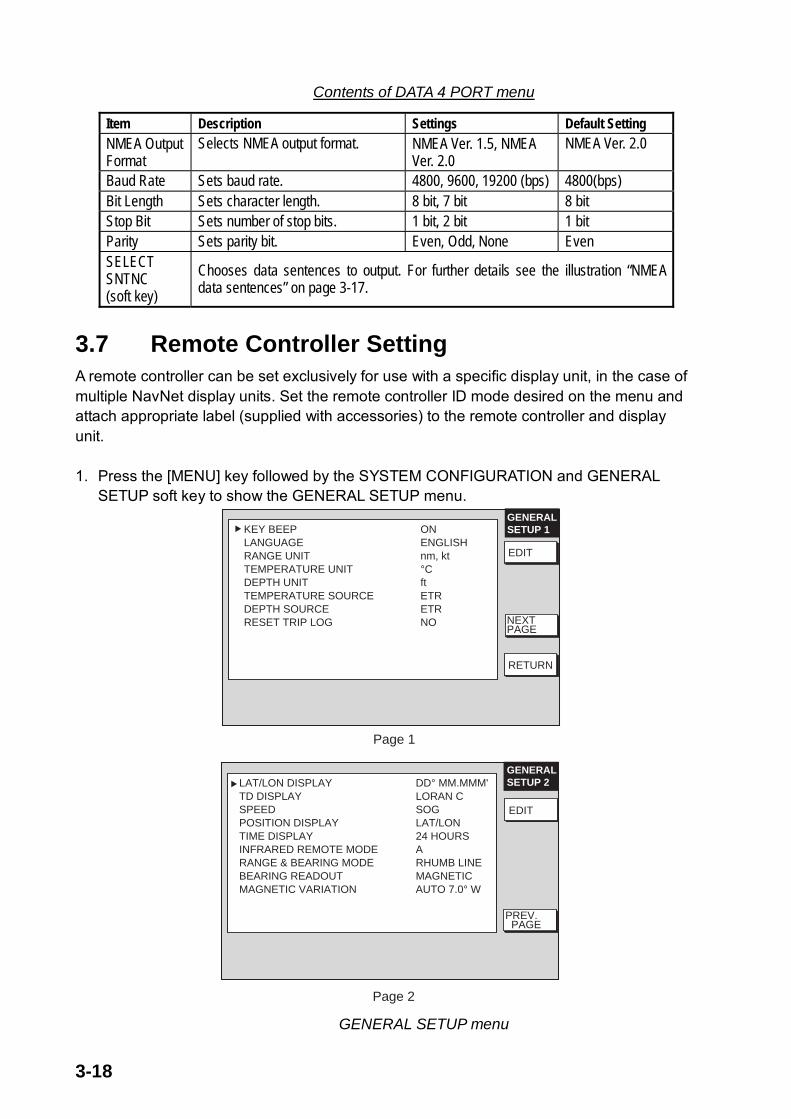
3.7 Remote Controller Setting A remote controller can be set exclusively for use with a specific display unit, in the case of multiple NavNet display units. Set the remote controller ID mode desired on the menu and attach appropriate label (supplied with accessories) to the remote controller and display unit.
1. Press the [MENU] key followed by the SYSTEM CONFIGURATION and GENERALSETUP soft key to show the GENERAL SETUP menu.
GENERALSETUP 1KEY BEEP ON
LANGUAGE ENGLISHRANGE UNIT nm, ktTEMPERATURE UNIT °CDEPTH UNIT ftTEMPERATURE SOURCE ETRDEPTH SOURCE ETRRESET TRIP LOG NO
Page 1
NEXTPAGE
EDIT
RETURN
EDITLAT/LON DISPLAY DD° MM.MMM'TD DISPLAY LORAN CSPEED SOGPOSITION DISPLAY LAT/LONTIME DISPLAY 24 HOURSINFRARED REMOTE MODE ARANGE & BEARING MODE RHUMB LINEBEARING READOUT MAGNETICMAGNETIC VARIATION AUTO 7.0° W
Page 2
GENERALSETUP 2
EDIT
PREV. PAGE
GENERAL SETUP menu

3-19
2. Press the NEXT PAGE soft key to show Page 2.3. Select INFRARED REMOTE MODE, and press the EDIT soft key.
The SELECT I/R REMOTE window appears.4. Point the remote controller toward the display unit, and press any key on the remote
controller. Preset mode appears in the remote controller ID mode window.
SELECT I/R REMOTE
ABCD
MODE
A
PRESS '0' AND '2' KEYTOGETHER TO CHANGE MODE.
Remote controller ID mode window
Select I/R REMOTE window 5. After the confirmation of the remote controller mode on the window, and press the [0]
and [2] key together on the remote controller to change the controller ID mode setting among A, B, C and D.
6. Operate the trackball so that the display ID should be the same as the controller modesetting.
7. Press the [MENU] key to close the menu.
3.8 Remote Display Setting MODEL 1800C/1900C series and GD-1900C NavNet display unit can be used as a remote display for FAR/FR-2805, 2105 series etc. by using optional cable assy MJ-B24LPF0008-100 (10 m), 200 (20 m) or 300 (30 m).
To use the display unit as remote display, do the following procedure.
1. Open the RADAR SETUP menu.2. Use the trackball or [ENTER] knob to select MONITOR MODE, and press the EDIT soft
key or [ENTER] knob.3. Select ON.4. Turn the MBS function off at the main radar.5. Turn the VIDEO ADJUST on at the NavNet display unit.6. Select “H” at the ANTENNA TYPE on the RADAR SETUP menu.
Note: TX blanking function is not available when the MONITOR MODE is ON. To set a TX blanking sector, select OFF from MONITOR MODE on the NavNet equipment, and then set the sector same as the main radar. Finally, set MONITOR MODE to ON.
When the MONITOR MODE is ON, the following functions are not available. •Tuning (auto/manual, on the RADAR SETUP menu)
•Antenna rotation (RADAR SETUP menu)
•TX sector blanking (RADAR DISPLAY SETUP menu)
•Watchman (RADAR DISPLAY SETUP menu)
•Pulse select (Soft key)

4-1
4. OPTIONS
4.1 ARP Kit ARP-11 Necessary parts
Name: ARP kit Type: ARP-11 Code no.: 008-523-050
Table 4-1 ARP-11 contents
Name Type Code No. QtyARP Board 18P9013 008-521-830 1
Pan head screw M3x6 C2700W 000-881-403 4
SQ9 000-801-850 1Spacer*
SQ15 000-801-779 3
Spring washer* M3 C5191W 000-864-204 3
*Not used1. Unscrew seven connecter nuts at the rear of the display unit.2. Unfasten 15 bind screws (M3x10) to remove the display cover.
Removing the display unit cover

4-2
3. Disconnect the PH5P connector from J1357 on the POWER Board (19P1005).4. Unfasten seven pan head screws (M3x8) to dismount the POWER Board and POWER
shield case from the display unit.
To J1357 on POWER Board
POWER shield case
POWER Board19P1005
Pan head screws(M3x8) 7 pcs.
SPU Board
ARP Board
J1357
P107
J112
Dismounting the POWER Board
5. Mate P107 on the ARP Board (option) to J112 on the SPU Board.6. Fix the ARP Board on the SPU Board with four pan head screws and spring washers
(supplied with option kit).7. Remount the POWER Board and power shield case with pan head screws (M3x8, 7pcs.)8. Attach the PH5P connector to J1357 on the POWER Board.9. Fasten screws in order shown on the next page to mount the display cover.

4-3
Order of fastening screws
10. Fasten seven connector nuts.

4-4
4.2 Connection of Video equipment / External Monitor/Remote Display
The above units can be connected to the MODEL1823C/1833C/1933C/1943C/1953C and GD-1900C by using the hole at the rear of the display unit. Remove the cover to use this hole. After connecting, cover the hole with soft putty to seal.
12:00
Video recorder, CCD camera etc.
VGA monitor
Remote display (ex. FMD-811)
CAUTIONEven though the display unit meets waterproof standard IPX-5, this modification can affect waterproofness. Watertight integrity cannot be guaranteed.
Connection of Video equipment/External monitor/remote display
4.2.1 Connecting video equipment The display unit can show the picture from the CCD camera, video recorder etc. which outputs composite signal in NTSC/PAL format, by using the optional NTSC/PAL interface kit.
Necessary parts
Name: NTSC/PAL Interface kit Type: OP03-175 Code no.: 008-523-070
Table 4-2 NTSC/PAL Interface kit contents
Name Type Code No. Qty Remarks
PIP board 19P1004 008-521-890 1 NTSC/PAL interface Board
Pan head screw M3x6 C2700W 000-881-403 4
Connector assy RCA-TMP-L230 000-144-615 1
Cable tie SG-130 000-809-171 3 w/foot for fixing
Rubber grommet MG-4 000-871-378 1

4-5
For connection with the CCD camera/video recorder, the following cable is necessary (local supply).
• Both side connectors: RCA connector (metal)
• Cable length: shorter than 10 m• 2.5C2V or 3C2V (Japan Industrial Standard (JIS), or the equivalent) coaxial cable
(Impedance: 75 Ω)
ConductorS = 0.19 mm∅ = 0.5 mm
2
Vinylsheath
Shield
Cable 3C2VInsulator
3C-2V cable, sectional view
1. Remove the display unit cover, POWER Board and power shield case referring to thestep 1 through 4 on the “4.1 ARP kit ARP-11.”
2. Attach the NTSC/PAL Interface Board to the SPU Board with four pan head screws(M3x6, supplied with optional kit) so that J700 connector on the NTSC/PAL InterfaceBoard faces to J107 on the SPU Board.
3. Attach the connector assy RCA-TMP-L230 to J701 on the NTSC/PAL Interface Board.
NTSC/PAL Interface Board
Pan head screws(M3x6, supplied with optional kit) 4pcs.
J700
J107
Connector assy RCA-TMP-L230
NTSC/PAL Interface Board attachment

4-6
4. Set two cable tie “legs” (supplied with option kit) as shown below.
Cable ties attachment.
5. Tie the connector assy with two cable ties attached at step 4.6. Remount the POWER Board and power shield case with pan head screws (M3x8, 5
pcs.)7. Attach the PH5P connector from SPU Board to J1357 on the POWER Board.8. Pass the connector assy through the saddle on the POWER Board.9. Remount the display unit cover referring to the illustration on page 4-3 so that the cable
runs through the hole the connector cover removed.10. Cut a “cross” in the grommet to pass the cable through it and then attach the grommet.
Display unit, passing the PIP cable 11. Fasten the ground wire of the connector assy with a pan head screw (M4x10) shown in
the above. Finally, cover the hole with soft putty to seal

4-7
4.2.2 Connecting external monitor
You can display the MODEL1823C/1833C/1933C/1943C screen on the external monitor, which accepts industrial standard VGA input by using the optional RGB output cable kit OP03-176. Supply monitor and interconnection cable (with HD-15P connectors of male, three rows of 15 pins) locally.
Necessary parts for external monitor
Name: RGB output cable kit Type: OP03-176 Code No.: 008-526-360
Name Type Code No. QtyCable assy. 15SDS/XHP10-005 000-144-511 1 Grommet MG-4 000-871-378 1
1. Unscrew 15 binding screws (M3x10, w/nylon washer) and seven connector nuts toremove the display unit cover.
2. Cut a “cross” in the grommet (to pass the cable).3. Pass the RGB output cable through the grommet hole at the rear of the display unit
cover and the saddle on the POWER Board, and then connect the XH connector (10P)of the RGB output cable to J110 on the SPU Board. Put the ground wire of the cableoutside of the cover.
4. Reassemble the display unit referring to the illustration on page 4-3.5. Fix the ground wire of the cable with one of two screws both sides of the connector hole.6. Finally, cover the hole with soft putty to seal
How to connect 15SDS/XHP10-005
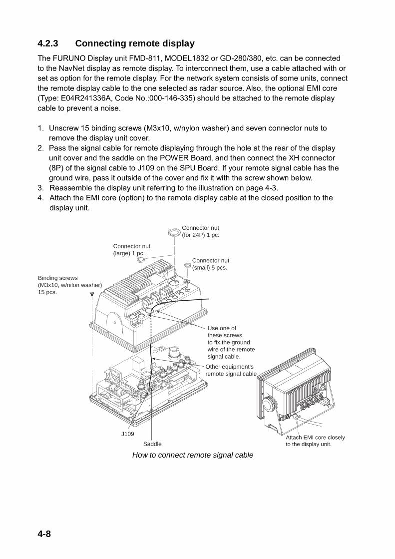
4-8
4.2.3 Connecting remote display The FURUNO Display unit FMD-811, MODEL1832 or GD-280/380, etc. can be connected to the NavNet display as remote display. To interconnect them, use a cable attached with or set as option for the remote display. For the network system consists of some units, connect the remote display cable to the one selected as radar source. Also, the optional EMI core (Type: E04R241336A, Code No.:000-146-335) should be attached to the remote display cable to prevent a noise.
1. Unscrew 15 binding screws (M3x10, w/nylon washer) and seven connector nuts toremove the display unit cover.
2. Pass the signal cable for remote displaying through the hole at the rear of the displayunit cover and the saddle on the POWER Board, and then connect the XH connector(8P) of the signal cable to J109 on the SPU Board. If your remote signal cable has theground wire, pass it outside of the cover and fix it with the screw shown below.
3. Reassemble the display unit referring to the illustration on page 4-3.4. Attach the EMI core (option) to the remote display cable at the closed position to the
display unit.
Connector nut(small) 5 pcs.
Connector nut(for 24P) 1 pc.
Connector nut(large) 1 pc.
Binding screws(M3x10, w/nilon washer)15 pcs.
Other equipment'sremote signal cable
Saddle
J109
Use one of these screws to fix the ground wire of the remote signal cable.
Attach EMI core closelyto the display unit.
How to connect remote signal cable

4-9
4.2.4 Attaching more than two units
When more than two cables of PIP kit, VGA monitor cable and remote signal cable, use the cable tie supplied as the installation material with the display unit to tie optional cables. Attach the cable tie to the hole on the POWER Board.
Attach the cable tie here.
Cable tie
Attaching the cable tie to POWER Board

4-10
4.3 Mounting the Memory Card Interface Unit The memory card interface CU-200 enables to use more two chart cards. Type: CU-200-NAV Code: 000-081-567
Name Type Code No. Qty
Memory card interface CU-200 000-081-569 1
Cable assy MJ-A6SPF/TM11AP
8C050 000-146-289 1
Cable assy MJ-A15A3F0003-030 000-145-513 1
Threaded rod M4X5 000-147-539 4
Hex. nut M4 000-863-106 4
Flat washer M4 000-864-126 4
Spring washer M4 000-864-256 4
Flush mounting
This unit can be flush-mounted in a panel with the standard installation materials. 1. Prepare a cutout in the mounting location, referring to the outline drawing at the end of
this manual. 2. Screw in the threaded rods to the flange of the front panel of the unit securely by hands.3. Set the unit to the cutout.4. Insert the flat washer, spring washer and nut in that order for each rod and fasten the
nuts.
Flush mounting

4-11
Desktop mount
For desktop mount, the optional desktop mount kit FP03-10201 (Code No.: 008-539-530) is required.
Name Type Code No. Qty
Mounting bracket 19-023-3081-0 100-316-250 1
Self-tapping screw 5x20 000-802-081 4
Screw M4x10 000-881-145 4
1. Put the mounting bracket 19-023-3081 on the unit.2. Fix the mounting bracket to the unit with four screws.3. Mount the above assembly on a desktop with four self-tapping screws.

NAME OUTLINE Q'TYDESCRIPTION/CODE
PACKING LIST 19AM-X-9851 -6 RDP-138/139 [E] 1/1
NAME OUTLINE Q'TYDESCRIPTION/CODE
UNIT
DISPLAY UNIT
RDP-138-E-N
000-080-037
1
**
REMOTE CONTROLLER SET
REMOTE
CONTROLLER
RMC-100
000-144-471
1
VINYL CASE FOR REMOTE CONTROLLER
14-034-2075-1
100-292-801
1
BATT(MN)
SIZE AA BATTERY
R6PKRCP-2
000-142-527
1
03-153-1314-2
100-292-792
1
LABEL FOR REMOTE
CONTROLLER
03-153-1315-2
100-292-822
1
LABEL FOR REMOTE
CONTROLLER
03-153-1316-2
100-292-832
1
LABEL FOR REMOTE
CONTROLLER
LABEL FOR REMOTE CONTROLLER
03-153-1317-2
100-292-842
1
SPARE PARTS SP03-14001
FUSE
FGBO 7A AC125V
000-549-013
3
FUSE
FGBO 15A AC125V
000-549-014
3
ACCESSORIES FP03-09301
CARD REMOVER
03-153-1311-0
100-292-130
1
INSTALLATION MATERIALS CP03-22701
CABLE TIE
SG-130
000-809-171
1
FUSE LABEL
03-153-1312-0
100-292-140
1
+TAPPING SCREW 5X20 SUS304 1シュ
000-802-081
4
WASHER HEAD
SCREW
M4X20 SUS304
000-804-742
6
TEMPLATE SHEET
19-022-1511-0
100-292-770
1
OTHER INSTALLATION MATERIALS
CABLE ASSY.
MJ-A3SPF0018-050Z
000-139-872
1
DOUBLE ASTERISK DENOTES COMMONLY USED EQUIPMENT.
(DIMENSIONS IN DRAWING FOR REFERENCE ONLY.) 19AM-X-9851

(DIMENSIONS IN DRAWING FOR REFERENCE ONLY.)

PACKING LISTPACKING LISTPACKING LISTPACKING LIST 19AO-X-9851 -1
RSB-0094-075RSB-0094-075RSB-0094-075RSB-0094-075
N A M E O U T L I N E DESCRIPTION/CODE Q'TY
1/1
UNITUNITUNITUNIT
ANTENNA UNIT
RSB-0094-075
000-080-237
1
INSTALLATION MATERIALSINSTALLATION MATERIALSINSTALLATION MATERIALSINSTALLATION MATERIALS CP03-25401CP03-25401CP03-25401CP03-25401
HEX.BOLT (SLOTTED HEAD)
M10X25 SUS304
000-862-308
4
EMIコア
EMI CORE
RFC-10
000-141-085
1
(DIMENSIONS IN DRAWING FOR REFERENCE ONLY.)

(DIMENSIONS IN DRAWING FOR REFERENCE ONLY.)

(DIMENSIONS IN DRAWING FOR REFERENCE ONLY.)

(DIMENSIONS IN DRAWING FOR REFERENCE ONLY.)
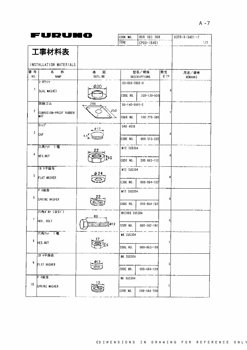
(DIMENSIONS IN DRAWING FOR REFERENCE ONLY.)
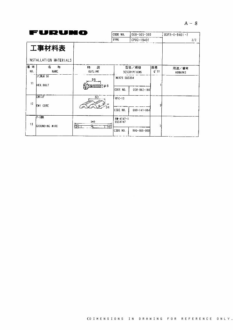
(DIMENSIONS IN DRAWING FOR REFERENCE ONLY.)
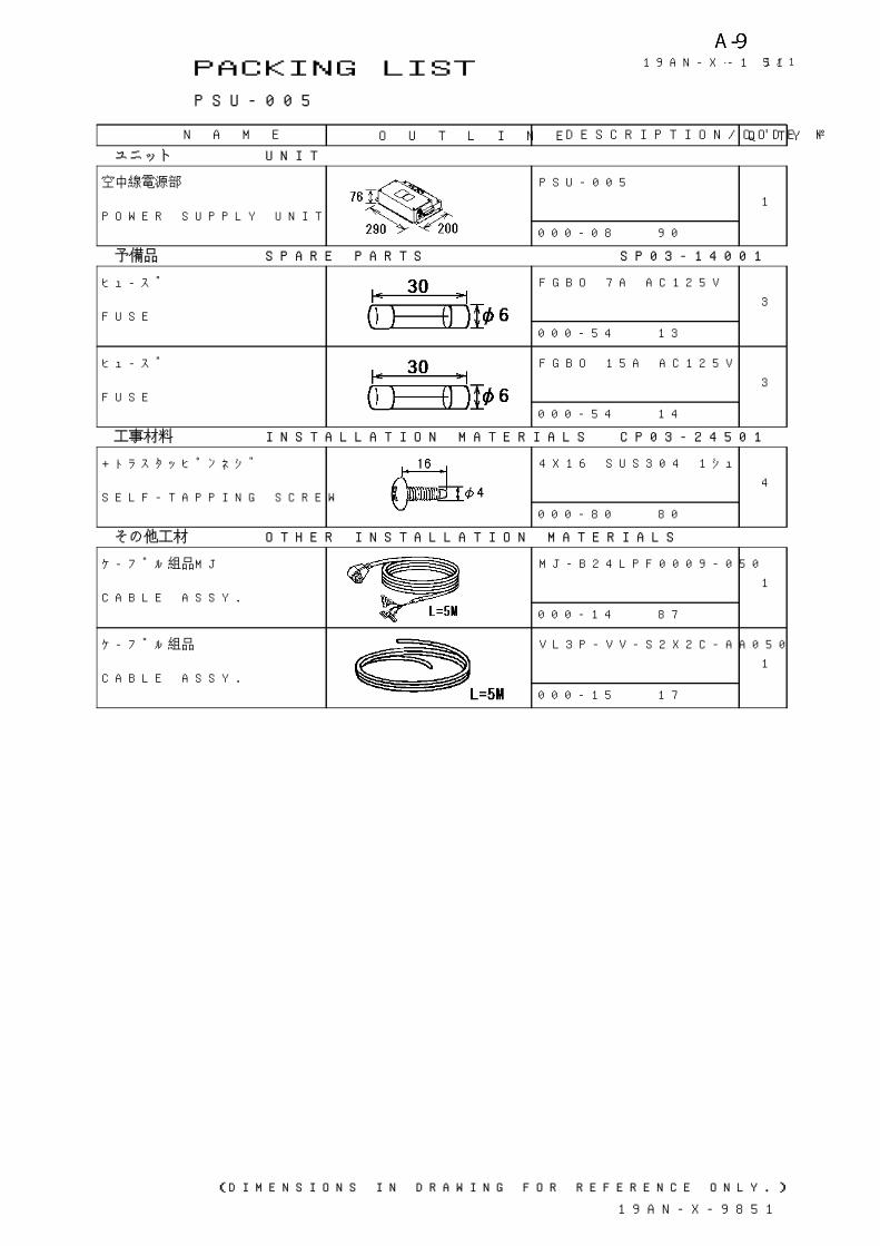
PACKING LIST 19AN-X-9851 -1
PSU-005
N A M E O U T L I N E DESCRIPTION/CODE Q'TY
1/1
ユニット UNIT
空中線電源部
POWER SUPPLY UNIT
PSU-005
000-080-190
1
予備品 SPARE PARTS SP03-14001
ヒューズ
FUSE
FGBO 7A AC125V
000-549-013
3
ヒューズ
FUSE
FGBO 15A AC125V
000-549-014
3
工事材料 INSTALLATION MATERIALS CP03-24501
+トラスタッピンネジ
SELF-TAPPING SCREW
4X16 SUS304 1シュ
000-802-080
4
その他工材 OTHER INSTALLATION MATERIALS
ケーブル組品MJ
CABLE ASSY.
MJ-B24LPF0009-050
000-145-887
1
ケーブル組品
CABLE ASSY.
VL3P-VV-S2X2C-AA050
000-152-217
1
(DIMENSIONS IN DRAWING FOR REFERENCE ONLY.)
19AN-X-9851


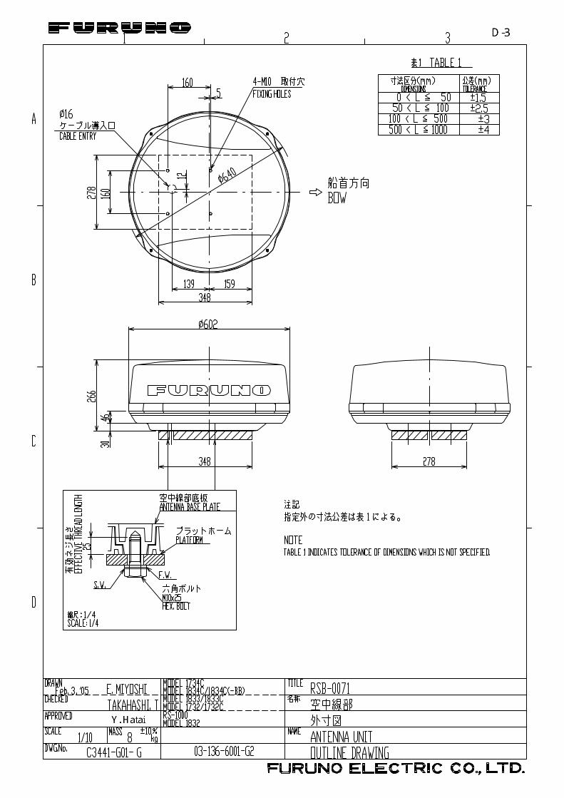


FURUNO ELECTRIC CO., LTD.
相互結線図
INTERCONNECTION DIAGRAM
船舶用レーダー
MARINE RADAR
MODEL 1833C
NAME
TYPE
名 称
kg
DRAWN
CHECKED
APPROVED
DWG.No.
SCALE MASS
1 2 4 5 63
B
A
D
C
*1. SHIPYARD SUPPLYNOTE
*2. CONNECTOR PLUG FITTED AT FACTORY.
*3. SHIELD SHOULD BE EFFECTIVELY GROUNDED AT BOTH UNIT ENDS.
19-022-0006- 3
K.MIYAZAWA
TAKAHASHI.T
DJ1 *2
MOTOR(+)
P/L AP/L B
+12V
GND
GND
GND-12V
+12V
-12VTX_TRIG
BEARING
HD SIG.
TUNE_IND.
VIDEOTUNE_CONT
(17C+2C2V,MAX.30m)
1011201415287
9117
MOTOR(-) 5
MBS_L 3
18
24
1621
6
*3
NC
NCNCNC
412131923
22SPARE
MJ-B24LPF0002,10/15/20/30m,φ11
シロ WHT
BLU
キ YEL
クロ BLK
BRN
シロ/アカ(太)
シロ/クロ(太)シロ/ミドリ(太)
シロ/ダイ(太)シロ/チャ(太)
アオ
チャ
WHT/RED[B]
WHT/BLK[B]WHT/GRN[B]
WHT/ORG[B]WHT/BRN[B]
WHT/BLU[B]シロ/アオ(太)
ミドリ GRN
ドウジク
モモ(太) PNK[B]
ダイ ORG
ムラサキ PPL
ハイ GRY
アカ RED
21 (+)
(-)クロ BLKシロ WHT
3
*2MJ-A3SRMD
GND
J1351
54321
67
GND
89
GND
GND
GND
GND10E_VSYNC_N
E_HSYNC_N
SIG-B
SIG-G
SIG-R
54321
678
21
PIP 19P1004
GND
GND
GND
GND
TRU_HD
DP_BP
OP_VIDEO
PR_TRIG
19P1001SPU
19S1004,0.5m
OP03-174,MAX.30m
4321
56
CLK-HCLK-C
*2
NC
MJ-A6SRMD
DATA-H/HDG-HDATA-C/HDG-C
SHIELD
RD3-BRD3-A
SHIELD/GNDEXT.BUZZ
RD_DTTD_DT
+12V
76
12345
MJ-A7SRMD*2
54321
67
+12V
SHIELDGND
MJ-A7SRMD*2 DATA1
J1356
54321
6
*2
1312111098765
*2
87
432
65
1
9
1234
1234
MD-9208
J611(NH13P)
2B2
2B3
J801(VH9P)
J802(VH4P)
*3
整流器RECTIFIER
(+)(-)
(VV-S 2.0x2C)
RU-3423
1 2 5 6
DISPLAY UNIT指 示 部RDP-138/139
空中線部 ANTENNA UNITRSB-0071/RTR-057
MJ-A6SRMD J1355DATA2
DATA3J1354
DATA4J1353
TD2-ATD2-BRD2-ARD2-BNCSHIELD
DPYC-1.5 *1
*1VGA MONITOR CABLE
VGA MONITORVGAモニター
VIDEO INTERFACEビデオI/F
副指示器
(NTSC/PAL)
GPS受信機GPS RECEIVER
ECHO SOUNDERPC(RS232C)
魚群探知機・PC
外部ブザーEXT. BUZZEROP03-136
D-SUB 15P
*1CO-AX CABLE
RCA JACK
19S1021,0.5m
MJ-A3SPF0018(03S9368),5m,φ10
10m
NAV/RADAR航法・レーダー
J110(XH10P)
J109(XH8P)
MJ-A7SPF0007,5m,φ7
MJ-A6SPF0003,5m,φ6
MJ-A6SPF0009,10m
φ6
MJ-A6SPF0003,5mMJ-A6SPF0012,5/10m(6P-6P)
MJ-A6SPF0007,10m,φ6
シロクロ
ミドキ
WHTBLKYELGRN
シロクロ
ミドキ
WHTBLKYELGRN
シロ
ミドキ
WHT
YELGRN
IF-9214A
アオ BLU
クロ BLK
NMEA0183
(RS-232C)
MJ-A6SPF0009,10m,φ6
GYRO
選択
SELECT
AD-100
ADコンバータA-D CONVERTER
HEADING SENSORPG-1000
ヘディングセンサ
GP-310B/320B
J701(VH2P)
IV-2SQ.*1GND
1φ,50/60 Hz100/110/220/230 VAC
FUSE
15 A: 12 VDC7 A: 24 VDC
TD1-ATD1-BRD1-ARD1-B
MJ-A7SPF0007,5m,φ7
VINAGND
NC
E_TD_PE_TD_NE_RD_PE_RD_N
SHIELD
4321
56
*2MJ-A6SRMD J1352
NETWORK
HUB
MAX.30mMJ-A6SPF0014,φ6
*1
ETR-6/10N
外部装置EXT. EQUIP.GP-1700/C
MAX.30mMJ-A6SPF0014,φ6MJ-A6SRMD/TM11AP8
(19S1005),0.5m
IV-2SQ. *1GND
12-24 VDC
*1)造船所手配
注 記
*2)コネクタは工場にて取付済み。
*3)シールドは両ユニット側で完全に接地すること。
*5)輸出仕様のみ。
アカ RED
メモリカードI/FMEMORY CARD I/FCU-200
MJ-A6SPF/TM11AP8-C050,5m,φ5.1
*5FGGND+12V
3
12
MJ-A15A3F0003-030アカ REDクロ BLK
FUSE1A
MJ-A3SRMD
3m,φ6.812 VDC
*5. OVERSEAS SPECIFICATION ONLY.
C3503-C01- H
*4)副指示器として使用する場合は、指示器の内部設定を変更する。
*4. CHANGE SETTING IN THE DISPLAY UNIT FOR USING AS A REMOTE DISPLAY.
REMOTE DISPLAY
1720924232116
*4
HD SIG.
DJ1
GNDBEARING
GND
GNDVIDEO
EXT_TRIG
8765
1234
RADARレーダー
*2MJ-B24LPF000810/20/30m,φ11.4(OPTION)
副指示器用 FOR REMOTE DISPLAY
*2
(NH8P)
EXT_TRIG
2C-2V COAX.
シロハイ
ドウジク
アカ
キクロ
GRYRED
YELBLK
WHT
2C-2V COAX.
GND
GND
GND
GND
HD
BP
TRIG
VIDEO
May 28 '04


FURUNO ELECTRIC CO., LTD.
NAME
TYPE
名 称
kg
DRAWN
CHECKED
APPROVED
DWG.No.
SCALE MASS
1 2 4 5 63
B
A
D
C
NOTE
*2. CONNECTOR PLUG FITTED AT FACTORY.
*3. SHIELD SHOULD BE EFFECTIVELY GROUNDED AT BOTH UNIT ENDS.
MODEL 1823C
船舶用レーダー
MARINE RADAR
相互結線図
INTERCONNECTION DIAGRAM03-161-6001-1
K.MIYAZAWA
TAKAHASHI.T
DJ1 *2
P/L AP/L B
+12V
GND-12V
+12V
-12VTX_TRIG
(17C+2C2V,MAX.30m)
1011201415287
MJ-B24LPF0002,10/15/20/30m,φ11
BLU
BRN
シロ/アカ(太)
シロ/クロ(太)シロ/ミドリ(太)
シロ/ダイ(太)シロ/チャ(太)
アオ
チャ
WHT/RED[B]
WHT/BLK[B]WHT/GRN[B]
WHT/ORG[B]WHT/BRN[B]
ムラサキ PPL
21 (+)
(-)クロ BLKシロ WHT
3
*2
GND
J1351
FUSE
54321
67
GND
89
GND
GND
GND
GND10E_VSYNC_N
E_HSYNC_N
SIG-B
SIG-G
SIG-R
54321
678
21
PIP 19P1004
GND
GND
GND
GND
TRU_HD
DP_BP
OP_VIDEO
PR_TRIG
19P1001SPU
19S1004,0.5m
OP03-174,MAX.30m
4321
56
CLK-HCLK-C
*2
NC
MJ-A6SRMD
DATA-H/HDG-HDATA-C/HDG-C
SHIELD
RD3-BRD3-A
SHIELD/GNDEXT.BUZZ
RD_DTTD_DT
+12V
76
12345
MJ-A7SRMD*2
54321
67
+12V
SHIELDGND
MJ-A7SRMD*2 DATA1
J1356TD4-ATD4-BRD4-ARD4-B
54321
6
*2
*2
87
432
65
1
9
J801(VH9P)
空中線部 ANTENNA UNIT
MJ-A6SRMD J1355DATA2
DATA3J1354
DATA4J1353
TD2-ATD2-BRD2-ARD2-BNCSHIELD
*1VGA MONITOR CABLE
VGA MONITORVGAモニター
VIDEO INTERFACEビデオI/F
副指示器
(NTSC/PAL)
GPS受信機GPS RECEIVER
ECHO SOUNDERPC(RS232C)
魚群探知機・PC
外部ブザーEXT. BUZZEROP03-136
*1CO-AX CABLE
19S1021,0.5m
7A:24V15A:12V
10m
NAV/RADAR航法・レーダー
MJ-A7SPF0007,5m,φ7
MJ-A6SPF0003,5m,φ6
MJ-A6SPF0009,10m
φ6
MJ-A6SPF0003,5mMJ-A6SPF0012,5/10m(6P-6P)
MJ-A6SPF0007,10m,φ6
シロクロ
ミドキ
WHTBLKYELGRN
シロクロ
ミドキ
WHTBLKYELGRN
シロ
ミドキ
WHT
YELGRN
アカ RED
アオ BLU
クロ BLK
1mNMEA0183
(RS-232C)
MJ-A6SPF0009,10m,φ6
GYRO
選択
SELECT
AD-100
ADコンバータA-D CONVERTER
HEADING SENSORPG-1000
ヘディングセンサ
GP-310B/320B
GND
GND
TUNE_IND.
VIDEOTUNE_CONT
MBS_L 3
18
24
1621
6
*3
NC
NCNCNC
412131923
22SPARE
キ YEL
ミドリ GRN
ドウジク
ダイ ORG
ハイ GRY
アカ RED
1312111098765
1234
*3
J810(NH13P)
MOTOR(+)BEARING
HD SIG.
9117
MOTOR(-) 5
シロ WHT
クロ BLKWHT/BLU[B]シロ/アオ(太)
モモ(太) PNK[B]
1234
J809(VH4P)
整流器RECTIFIER
(+)(-)
RU-3423
1 2 5 61φ,50/60Hz100/110/220/230VAC DPYC-1.5 *1
D-SUB 15P
RCA JACK
IV-2SQ.*1
MJ-A3SPF0017-050Z,5m,φ10(VV-S 2.0x2C)
MJ-A3SRMDZ1
2B4 03P9328
指 示 部
RDP-139DISPLAY UNIT RSB-0094-075
J105(XH8P)
J106(XH10P)
VINAGND
J701(VH2P)
GND
IV-2SQ. *1GND
NC
E_TD_PE_TD_NE_RD_PE_RD_N
SHIELD
4321
56
*2MJ-A6SRMD J1352
NETWORK
HUB
MAX.30mMJ-A6SPF0014,φ6
*1
ETR-6/10N
外部装置EXT. EQUIP.GP-1700/C
MAX.30mMJ-A6SPF0014,φ6MJ-A6SRMD/TM11AP8
(19S1005),0.5m
*1. SHIPYARD SUPPLY
12-24 VDC
注 記
*2)コネクタは工場にて取付済み。
*3)シールドは両ユニット側で完全に接地すること。
*1)造船所手配
*5)輸出仕様のみ。
メモリカードI/FMEMORY CARD I/FCU-200
MJ-A6SPF/TM11AP8-C050,5m,φ5.1
*5FGGND+12V
3
12
MJ-A15A3F0003-030アカ REDクロ BLK
FUSE1A
MJ-A3SRMD
3m,φ6.812 VDC
*5. OVERSEAS SPECIFICATION ONLY.
C3513-C01- D
1720924232116
*4
HD SIG.
DJ1
GNDBEARING
GND
GNDVIDEO 8
765
1234
RADARレーダー
*2MJ-B24LPF000810/20/30m,φ11.4(OPTION)
*4)副指示器として使用する場合は、指示器の内部設定を変更する。
REMOTE DISPLAY
*4. CHANGE SETTING IN THE DISPLAY UNIT FOR USING AS A REMOTE DISPLAY.
副指示器用 FOR REMOTE DISPLAY
*2
(NH8P)
GND
GND
GND
GNDEXT_TRIG
EXT_TRIG
2C-2V COAX.
HD
BP
TRIG
VIDEO
シロハイ
ドウジク
アカ
キクロ
GRYRED
YELBLK
WHT
2C-2V COAX.
May 28 '04

FURUNO ELECTRIC CO., LTD.
1 2 4 5 63
B
A
D
C
相互結線図
INTERCONNECTION DIAGRAM
船舶用レーダー
MARINE RADAR
MODEL 1933C/1943C
NAME
TYPE
名 称
kg
DRAWN
CHECKED
APPROVED
DWG.No.
SCALE MASS
19-022-0007- 3
21 (+)(-)クロ BLK
シロ WHT
3 GND
J1351
19S1004,0.5m
OP03-174,MAX.30m
4321
56
CLK-HCLK-CNC
DATA-H/HDG-HDATA-C/HDG-C
SHIELD
RD3-BRD3-A
SHIELD/GNDEXT.BUZZ
RD_DTTD_DT
+12V
76
12345
54321
67
+12V
SHIELDGND
DATA1J1356
54321
6
(VV-S 2.0x2C)
D-SUB 15P
DISPLAY UNIT指 示 部RDP-138/139
J1355DATA2
DATA3J1354
DATA4J1353
TD2-ATD2-BRD2-ARD2-BNCSHIELD
*1VGA MONITOR CABLEVGA MONITOR
VGAモニター
VIDEO INTERFACEビデオI/F
副指示器
(NTSC/PAL)GPS受信機GPS RECEIVER
ECHO SOUNDERPC(RS232C)
魚群探知機・PC
外部ブザーEXT. BUZZEROP03-136
DJ1
MOTOR(+)
P/L AP/L B
+12V
GND-12V
+12V
-12VTX_TRIG
BEARING
HD SIG.
1011201415287
9117
MOTOR(-) 5
(17C+2C2V,MAX.30m)MJ-B24LPF0005,10/15/20/30m,φ11 空中線部 ANTENNA UNIT
87
432
65
1
9
1234
J823(VH4P)
J8211(VH9P)
RSB-0070/0073
*1 RCA JACKCO-AX CABLE
19S1021,0.5m
MJ-A3SPF0018(03S9368),5m,φ10
10m
NAV/RADAR航法・レーダー
MJ-A6SPF0009,10m
φ6MJ-A6SPF0012,5m(6P-6P)MJ-A6SPF0003,5m
MJ-A7SPF0007,5m,φ7
MJ-A6SPF0003,5m,φ6
MJ-A6SPF0007,10m,φ6
シロクロキ
WHTBLKYELGRN
シロクロキ
WHTBLKYELGRN
シロ
キ
WHT
YELGRN
アカ RED
アオ BLU
クロ BLK
NMEA0183
(RS-232C)
GYRO
選択SELECT
AD-100
ADコンバータA-D CONVERTER
HEADING SENSORPG-1000
ヘディングセンサ
MJ-A6SPF0009,10m,φ6
GP-310B/320B
TD1-BTD1-A
RD1-ARD1-B
FUSE
15 A: 12 VDC7 A: 24 VDC
MJ-A7SPF0007,5m,φ7
TAKAHASHI.T
GND
NC
E_TD_PE_TD_NE_RD_PE_RD_N
SHIELD
4321
56
J1352NETWORK
MAX.30mMJ-A6SPF0014,φ6
ETR-6/10N
外部装置EXT. EQUIP.GP-1700/C
MAX.30mMJ-A6SPF0014,φ6
HUB*1 MJ-A6SRMD/TM11AP8
12-24 VDC
*1. SHIPYARD SUPPLYNOTE
MJ-A6SPF/TM11AP8-C050,5m,φ5.1FGGND+12V
3
12
アカ REDクロ BLK
REMOTE DISPLAY
1720924232116
HD SIG.
DJ1
GNDBEARINGGND
GNDVIDEO
EXT_TRIG
8765
1234
RADARレーダー
(NH8P)
GND
GND
GND
GND
HD
BP
TRIG
VIDEO
Nov.18,'04 E.MIYOSHI
C3505-C01- K
MJ-A3SPF
MJ-A7SPF
MJ-A6SPF
MJ-A6SPF
MJ-A7SPF
MJ-A6SPF
(19S1005),0.5m
MJ-A3SPFFUSE1A
12 VDC3m,φ6.8MJ-A15A3F0003
54321
67GND
89
GND
GND
GND
GND10E_VSYNC_N
E_HSYNC_N
SIG-B
SIG-G
SIG-R
54321
678
21
GND
GND
GND
GND
TRU_HD
DP_BP
OP_VIDEO
PR_TRIG
19P1001SPU
J110(XH10P)
J109(XH8P)
VINAGND
J701(VH2P)
100/110/220/230 VAC1φ,50/60 Hz
DPYC-1.5 *1
整流器RECTIFIER
(+)(-)
RU-3423
1 2 5 6
IV-2SQ.*1GND
メモリカードI/FMEMORY CARD I/FCU-200
YEL[B]BLK[B]RED[B]WHT[B]BRN[B]BRNBLUGRN
WHTBLU[B]BLKPPL[B]
キ(太)クロ(太)アカ(太)シロ(太)チャ(太)チャアオミドリ
シロアオ(太)クロムラサキ(太)
GND
GND
TUNE_IND.
VIDEOTUNE_CONT
MBS_L 3
18
24
1621
6
SPARESPARE
1312111098765
1234
12
03P9249
J824(NH13P)
J822(NH13P)
RSB-0070: 24rpmRSB-0073: 48rpm
1312
MOTOR (-) 22
MOTOR (+) 19
MOTOR (+) 4
WHT/BRNPPL
WHT/REDREDORG
WHT/ORG
2C-2V COAX.YEL
GRN[B]ORG[B]
シロ/チャムラサキ
シロ/アカアカダイ
シロ/ダイ
ドウジクキ
ダイ(太)ミドリ(太)
23EXT_TRIG
注 記
*2)オプション。*1)造船所手配。
*6. OVERSEAS SPECIFICATION ONLY.
*6
*5. CHANGE SETTING IN THE DISPLAY UNIT FOR USING AS A REMOTE DISPLAY.*4. SHIELD SHOULD BE EFFECTIVELY GROUNDED AT BOTH UNIT ENDS.
*4*4
*3. CONNECTOR PLUG FITTED AT FACTORY.
*3*3
*3
*3*3
*3
*3
*3
*3
*3
*2. OPTION.
*3
*3)コネクタは工場にて取付済み。*4)シールドは両ユニット側で完全に接地すること。*5)副指示器として使用する場合は、指示器の内部設定を変更する。*6)輸出仕様のみ。
*2
MJ-B24LPF0008,10/20/30m,φ11.4
シロハイ
ドウジク
アカ
キクロ
GRYRED
YELBLK
WHT
2C-2V COAX.
PIP 19P1004
IV-2SQ.*1
ミドリ
ミドリ
ミドリ
副指示器用 FOR REMOTE DISPLAY
*5
*2

FURUNO ELECTRIC CO., LTD.
1 2 4 5 63
B
A
D
C
19S1004,0.5m
54321
67
+12V
SHIELDGND
*2 DATA1J1356
54321
6
*2J1355DATA2
TD2-ATD2-BRD2-ARD2-BNCSHIELD
19S1021,0.5m
シロクロ
ミドキ
WHTBLKYELGRN
4321
56
CLK-HCLK-C
*2
NC
DATA-H/HDG-HDATA-C/HDG-C
SHIELD
DATA3J1354
シロクロ
ミドキ
WHTBLKYELGRN
RD3-BRD3-A
SHIELD/GNDEXT.BUZZ
RD_DTTD_DT
+12V
76
12345
NMEA0183
*2 DATA4J1353
シロ
ミドキ
WHT
YELGRN
アカ RED
54321
67GND
89
GND
GND
GND
GND10E_VSYNC_N
E_HSYNC_N
SIG-B
SIG-G
SIG-R
54321
678
21
PIP
GND
GND
GND
GND
TRU_HD
DP_BP
OP_VIDEO
PR_TRIG
SPU
J110(XH10P)
J109(XH8P)
ECHO SOUNDERPC(RS232C)
魚群探知機・PC
外部ブザーEXT. BUZZEROP03-136
MJ-A7SPF0007,5m,φ7
*1VGA MONITOR CABLEVGA MONITOR
VGAモニター
ビデオI/F
副指示器
(NTSC/PAL)GPS受信機GPS RECEIVER
*1CO-AX CABLE
GP-310B
NAV/RADAR航法・レーダー
選択SELECT
AD-100
ADコンバータA-D CONVERTER
HEADING SENSORPG-1000
ヘディングセンサNMEA
AD-10/
GYRO
MJ-A6SPF0007
MJ-A6SPF0003,5m,φ6
10m
VIDEO I/F
19P1004
19P1001
TUNE_CONT
MOTOR(+)
P/L AP/L B
+12V
GND
GND
GND-12V
+12V
-12VTX_TRIG
BEARING
HD SIG.
VIDEO
1011201415287
9117
MOTOR(-) 5
MBS_L 3
18
24
1621
6
23
19
1213
1312111098765
87
432
65
1
9
1234
1234
*3
TUNE_IND.
TUNE_CONT
MOTOR(+)
P/L AP/L B
+12V
GND
GND
GND-12V
+12V
-12VTX_TRIG
BEARING
HD SIG.
VIDEO
1011201415287
9117
MOTOR(-) 5
MBS_L 3
18
24
1621
6
(17C+2C2V,MAX.30m)MJ-B24LPF0005,10/15/20/30m,φ11
*3NC 23
1312111098765
*2
87
432
65
1
9
1234
1234
*3
12
J824(NH13P)
J823(VH4P)
キ(太) YEL[B]クロ(太) BLK[B]アカ(太) RED[B]シロ(太) WHT[B]チャ(太) BRN[B]
アオ BLUチャ BRN
ミドリ GRN
シロ WHTアオ(太) BLU[B]クロ BLK
ムラサキ(太) PPL[B]
22
19
GRN1312
+12V-12V
YEL
4 ORG
ORG[B]
WHT/ORG
ミドリ
キ
アカダイ
ダイ(太)
シロ/ダイ
ドウジク
シロ/アカREDWHT/RED
ムラサキシロ/チャ WHT/BRN
PPL
MJ-B24LPF0009,5m,φ11(RW-8577)
321 (+)
(-)
J3(VH9P)
J1(VL3P)
J4(VH4P)
J5(NH13P)
321J2(VL3P)15A:12V
7A:24V空中線部 ANTENNA UNIT
電源部PSU-005
POWER SUPPLY UNIT
IV-2SQ. *1GND
RSB-0072(24rmp)RSB-0073(48rmp)
03P9250
19P1006
DJ1
SPARESPARE
D-SUB 15P
RCA JACK
03S9299,10m
MJ-A6SPF0012,5/10m,φ6
10m,φ6
*3
22
4
SPARE
SPARE
SPARE
TUNE_IND
*2
アオ BLU
BLKクロ
相互結線図
INTERCONNECTION DIAGRAM
船舶用レーダー
MARINE RADAR
MODEL 1953C
NAME
TYPE
名 称
DRAWN
CHECKED
APPROVED
DWG.No.
SCALEkg
MASS
J6
21
クロ BLKシロ WHT
3
*2
指 示 部RDP-139
DISPLAY UNIT
FUSE
(+)(-)GND
J1351
DPYC-1.5 *1
(+)(-)1 2 5 6整流器RECTIFIERRU-3423
(03S9638)MJ-A3SPF0018-050Z,5m,φ10 7A
GNDIV-2SQ.
*1
J821(VH9P)
J822(VH2P)
VINAGND
J701(VH2P)
TD1-ATD1-BRD1-ARD1-B
100/110/220/230 VAC1φ,50/60 Hz
12-24 VDC
12-24 VDC
TAKAHASHI.T
NC
E_TD_PE_TD_NE_RD_PE_RD_N
SHIELD
4321
56
*2J1352NETWORK
IV-2SQ. *1GND
MAX.30mMJ-A6SPF0014,φ6
HUB*1 MJ-A6SRMD/TM11AP8
(19S1005),0.5m
MAX.30mMJ-A6SPF0014,φ6
ETR-6/10N
外部装置EXT. EQUIP.GP-1700/C
メモリカードI/FMEMORY CARD I/FCU-200
MJ-A6SPF/TM11AP8-C050,5m,φ5.1FGGND+12V
3
12
アカ REDクロ BLK
FUSE 1A
MJ-A15A3F0003-030
3m,φ6.8
12VDC
REMOTE DISPLAY
*5
1720924232116
*4
HD SIG.
DJ1
GNDBEARINGGND
GNDVIDEO
EXT_TRIG
8765
1234
RADARレーダー
*2MJ-B24LPF000810/20/30m,φ11.4(OPTION)
*2
(NH8P)
EXT_TRIG
2C-2V COAX.
シロハイ
ドウジク
アカ
キクロ
GRYRED
YELBLK
WHT
2C-2V COAX.
GND
GND
GND
GND
HD
BP
TRIG
VIDEO
E. MIYOSHI
VL3P-VV-S2X2C-AA050,5m,φ10(03S9801)
MJ-A3SPF
MJ-A6SPF
MJ-A7SPF
MJ-A6SPF
MJ-A6SPF
MJ-A3SPF
MJ-A7SPF
*2
MOTOR(-)
MOTOR(+)
MOTOR(+)
C3512-C01- J 19-022-0010- 4
副指示器用 FOR REMOTE DISPLAY
RW-4747
MAY 19, '05
NOTE
*2. CONNECTOR PLUG FITTED AT FACTORY.*3. SHIELD SHOULD BE EFFECTIVELY GROUNDED AT BOTH UNIT ENDS.
*1. SHIPYARD SUPPLY.
*4. CHANGE SETTING IN THE DISPLAY UNIT FOR USING AS A REMOTE DISPLAY.*5. OVERSEAS SPECIFICATION ONLY.
注 記*1)造船所手配*2)コネクタは工場にて取付済み。*3)シールドは両ユニット側で完全に接地すること。*4)副指示器として使用する場合は、指示器の内部設定を変更する。*5)輸出仕様のみ。
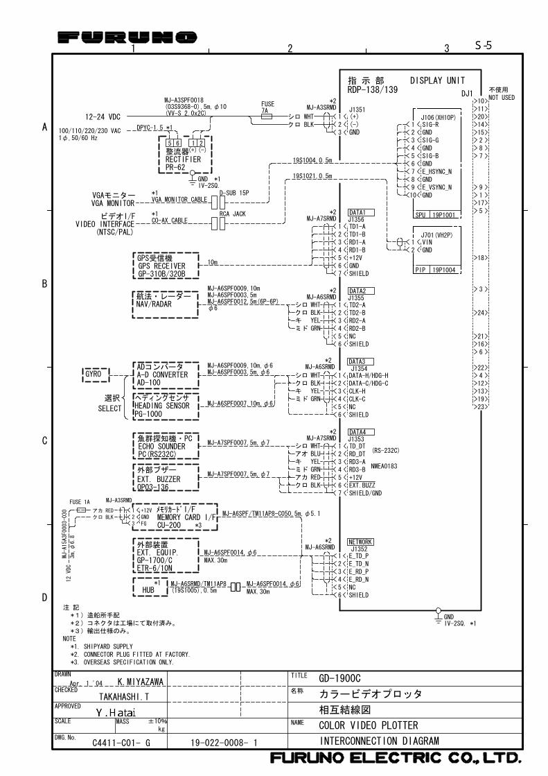
名称
TITLE
NAME
D
A
B
C
2 31
MASS
DRAWN
CHECKED
APPROVED
SCALE
DWG.No.
kg±10%
相互結線図
INTERCONNECTION DIAGRAM
GD-1900C
カラービデオプロッタ
COLOR VIDEO PLOTTER
19-022-0008- 1C4411-C01- G
TAKAHASHI.T
K.MIYAZAWA
21 (+)
(-)クロ BLKシロ WHT
3
*2MJ-A3SRMD
GND
J1351
19S1004,0.5m
4321
56
CLK-HCLK-C
*2
NC
MJ-A6SRMD
DATA-H/HDG-HDATA-C/HDG-C
SHIELD
RD3-BRD3-A
SHIELD/GNDEXT.BUZZ
RD_DTTD_DT
+12V
76
12345
MJ-A7SRMD*2
54321
67
+12V
SHIELDGND
MJ-A7SRMD*2 DATA1
J1356
54321
6
*2
整流器RECTIFIER
(+)(-)
(VV-S 2.0x2C)
D-SUB 15P
DISPLAY UNIT指 示 部RDP-138/139
MJ-A6SRMD J1355DATA2
DATA3J1354
DATA4J1353
TD2-ATD2-BRD2-ARD2-BNCSHIELD
54321
67
GND
89
GND
GND
GND
GND10E_VSYNC_N
E_HSYNC_N
SIG-B
SIG-G
SIG-RJ106(XH10P)
21
PIP 19P1004
19P1001SPU
DJ11011201415287
91175
3
18
24
1621
6
412131923
22
DPYC-1.5 *1
VGA MONITORVGAモニター
VIDEO INTERFACEビデオI/F
(NTSC/PAL)
*1VGA MONITOR CABLE
MJ-A6SPF0003,5m,φ6
ECHO SOUNDERPC(RS232C)
魚群探知機・PCMJ-A7SPF0007,5m,φ7
外部ブザーEXT. BUZZEROP03-136
NOT USED不使用
1 25 6
PR-6219S1021,0.5m
RCA JACK*1CO-AX CABLE
NAV/RADAR航法・レーダー
GPS受信機GPS RECEIVER
MJ-A6SPF0009,10m
φ6MJ-A6SPF0012,5m(6P-6P)MJ-A6SPF0003,5m
10m
MJ-A3SPF0018(03S9368-0),5m,φ10 FUSE
7A
MJ-A6SPF0007,10m,φ6
シロクロ
ミドキ
WHTBLKYELGRN
シロ
ミドキ
WHT
YELGRN
アカ RED
シロクロ
ミドキ
WHTBLKYELGRN
アオ BLU
クロ BLK
GP-310B/320B
MJ-A6SPF0009,10m,φ6
NMEA0183
(RS-232C)
選択
SELECT
AD-100
ADコンバータA-D CONVERTER
HEADING SENSORPG-1000
ヘディングセンサ
GYRO
J701(VH2P)VINGND
GNDIV-2SQ.
*1
TD1-ATD1-BRD1-ARD1-B
100/110/220/230 VAC1φ,50/60 Hz
MJ-A7SPF0007,5m,φ7
NC
E_TD_PE_TD_NE_RD_PE_RD_N
SHIELD
4321
56
*2MJ-A6SRMD J1352
NETWORK
IV-2SQ. *1GND
MAX.30mMJ-A6SPF0014,φ6
ETR-6/10N
外部装置EXT. EQUIP.GP-1700/C
MAX.30mMJ-A6SPF0014,φ6
HUB*1 MJ-A6SRMD/TM11AP8
(19S1005),0.5m
12-24 VDC
NOTE
注 記
*2)コネクタは工場にて取付済み。*1)造船所手配
*2. CONNECTOR PLUG FITTED AT FACTORY.*1. SHIPYARD SUPPLY
*3)輸出仕様のみ。
メモリカードI/FMEMORY CARD I/FCU-200
MJ-A6SPF/TM11AP8-C050,5m,φ5.1
FGGND+12V
3
12
MJ-A3SRMD
アカ RED
クロ BLK
FUSE 1A
MJ-A15A3F0003-030
3m,φ
6.8
12VDC
*3
Apr. 1 '04
*3. OVERSEAS SPECIFICATION ONLY.