Embed Size (px)
Citation preview
Model 5000Model 5000
FLOW-THROUGHFURNACE HUMIDIFIER
Installation/OperatingInstructions
FREQUENTLY ASKED QUESTIONS
QUESTION: Why use a flow-through style humidifier rather thana drum style humidifier?
ANSWER: This will depend on several factors including size ofhome, type of furnace, and size of ducting; as well as personalpreference. However in order to use this model flow through youwill require at least 10" wide ducting where as our drum styleswill fit on 8" wide ducting.
COMMENT: Flow-through and rotating-drum style evaporativefurnace humidifiers will safely and efficiently humidify 90% ofhomes which use forced air heating. As a manufacturer of bothstyles there are pro’s and con’s to be considered when choosinga flow through or drum style. A drum-style humidifier willtypically have a higher output when compared to a flow throughof equal size, however with today’s modern home constructionand insulation techniques the higher capacities are not required,over humidification is something that should be well guardedagainst. Another point to consider is the fact that a drum stylehumidifier is 100% efficient (meaning that all the water suppliedto the unit is delivered to the air) where as the flow through stylesrange anywhere from 30% to 40% efficient (meaning that forevery gallon of water delivered to the air 2 gallons will be allowedto flow through). Today, indoor air quality (IAQ) is an issue oneverybody’s mind and the inefficiency of flow throughhumidifiers is by design as the water flowing through serves toflush away any unwanted minerals and such leaving only cleanwater to be evaporated. The cost of maintaining (typically aevaporator pad once a year) and operating a flow through style isfar less when compared to the cost of maintaining a drum stylehumidifier to ensure healthy and efficient operation.
QUESTION: What type of furnaces will this humidifier work on?
ANSWER: The unit will work on most forced air furnaces whichincorporates a heating source, a supply duct, and a return duct.
COMMENT: The technology used in this humidifier to deliverwater to the air is not new, it is the simplest and easiest style abypass type evaporative humidifier. Your furnace fan creates apressure difference between the supply (hot) air and the return(cold) air. By installing a bypass tube between the supply and returnair a small amount of air is forced (via the pressure difference)toflow from the supply duct through the humidifier’s evaporator padand back into the return duct where it will mix with all the returnair from your home. As the hot air passes through the evaporatorpad it will “evaporator” moisture and deliver it to your home. Whatwill differ from furnace to furnace or home to home is how muchmoisture or capacity you will get from the unit. There are manyfactors which will affect this: How old is your home? How old isyour furnace? How well insulated is your home? For example, thecapacity of the unit is 12 US gallons per 24 hours of operation. Thisis based on ARI standards (120°F hot air temp, 60°F water supplytemp, 0.5" static pressure difference between supply and return)used by all humidifier manufacturers. If your furnace is a hiefficiency or pulse type furnace the hot air temperature may be lessor the length of time the furnace burner is on may be less; thereforeas a rule of thumb we would say you would get approx 75% to80% of the rated output. Generally speaking high-efficient furnacesare used in homes which are very well insulated and therefore the75% or 80% capacity will be more than enough to humidify thehome.
QUESTION: How much moisture does the humidifier deliver tothe air in my home?
ANSWER: This model will deliver 12 US Gallons (10 Imp.Gallons, 45.5 Litres) per 24 hrs of operation..
COMMENT: 24 Hrs of operation means continues humidifieroperation. This unit delivers sufficient moisture to humidify theaverage home up to 3200 sq ft. The humidifier will ensure thatwhen your furnace is heating it is delivering humidified air toyour home.
QUESTION: How much water does this humidifier use?
ANSWER: This humidifier incorporates a restrictor which metersthe amount of water supplied to the unit. In a average home theunit will use 37 US Gallons (31 Imp. Gallons, 140 Litres) per 24hrs of operation.
COMMENT: Your furnace will not run continuously 24 hrs a day;in an average home the 36 gallons will be used over a 3 dayperiod.
QUESTION: I’m replacing an old humidifier on my furnace canI use the old components?
ANSWER: You should replace all the components to ensure goodoperation. You may be able to utilize the existing duct cut outs forthe new installation (see section in the instructions.)
COMMENT: As a rule we like to see you change all thecomponents, particularly the water supply tube, as over timeminerals, solids, or sludge may have built up, these will veryquickly clog the water inlet of the flow through, or over time thetube may have become worn or leaky. Replace the bypass ductas well there may be secondary dampers unseen which will blockair or again there may be unseen wear which will cause air leaks.Same with electrical components or wiring these may bemalfunctioning or worn out. If you have a humidifier which wasinterlocked with your furnace (meaning the humidifier only cameon when the furnace came on) then the old transformer is gettingpower from the internal furnace wiring. You should leave thistransformer and wiring in place; if this transformer is functioningand it is 24 Volts AC, you may be able to utilize it to control thenew humidifier.
QUESTION: I’ve installed the humidifier on my furnace and it isfunctioning properly but I do not feel anything and the humidistatreading is not changing, is the humidifier working?
ANSWER: As long as there is hot air going through the humidifierand there is water getting to the evaporator pad moisture is beingdelivered to the air in your home.
COMMENT: All year, and especially during the winter monthswhen many combustion appliances are operating in your home,fresh air is required to ensure a healthy environment for yourfamily. Do not think of your home as a sealed bubble, no matterhow well insulated. All houses breath (some more than others)the cold outside air mixes with the air in your home constantly,even when your furnace is not running. A furnace humidifier willwork to offset the constant effect the dry outside air has on yourhome, and your home’s furnishings. Throughout the winter thereis a constant diminishing and replenishing of moisture levels inthe home, conditions inside and out rarely remain stagnant forany length of time.
2 Model 5000 Flow Through Humidifier

• READ THESE INSTRUCTIONS FULLY BEFORE INSTALLINGTHIS HUMIDIFIER.
• SAVE THESE INSTRUCTIONS FOR REFERENCE.
• WHEN DRILLING OR CUTTING INTO DUCTING BEEXTREMELY CAREFUL NOT TO DAMAGE AIR-CONDITIONING COILS OR OTHER FURNACE APPARATUS.
• THIS UNIT MUST BE INSTALLED ON 10” WIDE DUCTINGMINIMUM.
• FOR THIS UNIT TO OPERATE PROPERLY YOUR FURNACESHOULD ACHIEVE A HEATING TEMPERATURE OF AT LEAST35°C IN ONE MINUTE. IF IT DOES NOT YOU MAY HAVE TOPURCHASE A PRESSURE ACTIVATION SWITCH (SOLDSEPARATELY)
• DO NOT INSTALL THIS UNIT WHERE EXTREMETEMPERATURES EXIST (BELOW 45°F – ABOVE 145°F).
• THIS UNIT REQUIRES A DRAIN TO ALLOW WATER TOFREELY RUN OFF.
• FOR THIS UNIT TO OPERATE PROPERLY IT MUST BEINSTALLED ON A FORCED AIR HEATING SYSTEM WITH ASUPPLY DUCT and A RETURN DUCT.
• THE HUMIDIFIER BODY and THE BYPASS COLLAR DAMPERARE TO BE INSTALLED ON DUCTING ONLY. UNDER NOCIRCUMSTANCES MOUNT EITHER COMPONENT TO THEFURNACE BODY.
• ELECTRICAL WIRING, WATER SUPPLY and DRAIN TUBEMUST NOT KINK OR COME INTO CONTACT WITH SHARPEDGES OR HOT SURFACES.
• IF REPLACING AN EXISTING FURNACE HUMIDIFIER, WERECOMMEND YOU REPLACE ALL COMPONENTS TOENSURE PROPER HUMIDIFIER OPERATION.
• THE INSTALLATION OF THIS PRODUCT MUST COMPLYWITH NATIONAL AND LOCAL ELECTRICAL, PLUMBING,BUILDING, AND MECHANICAL CODES.
REQUIRED TOOLS• Safety glasses
• Work gloves
• Electric drill
• Drill bits (3/8", 1/8", 5/64")
• Tin snips
• Full size Philips or Roberstons screw driver
• Short handle Philips or Roberstons screw driver
• Adjustable wrench
• Utility knife
• Pliers
• Level
• Measuring tape or ruler
• Medium-grit sand paper
• Pencil
• Tape
SELECTION OF LOCATION TO MOUNT THE HUMIDIFIER
All bypass type furnace humidifiers rely on the pressuredifference which exists between the supply duct (hot air) and thereturn duct (cold air) to create and air-flow through thehumidifier’s evaporator pad. The air will ALWAYS flow from HOT(high pressure) to COLD (low pressure).
Selecting the proper location, and installing the humidifierproperly as intended by the manufacturer is imperative for theproper operation of the humidifier – see illustrations below alongwith the brief explanations as to what is a good installation andwhat is not.
• INSTALLATION TIP: Before starting fully plan out theinstallation. Check for the locations of the humidifier,bypass collar and damper, the length and type of ductingrequired, the water supply, the water drain, the electricalwiring, and a constant 120 volt outlet to plug in thetransformer. This will ensure your installation goes aseasy and quickly as possible.
1. The humidifier body and bypass tube are installed at eye level,easily accessible for installation and routine maintenance.
2. The space between the humidifier body and bypass tube are nomore than 30" to ensure maximum air flow through the humidifier.
3. The aluminum flex bypass tube are cut to the proper lengthand pulled tight to ensure maximum air flow.
3Model 5000 Flow Through Humidifier
INSTALLATION AND OPERATING INSTRUCTIONS: MODEL 5000 FLOW THROUGH HUMIDIFIER
IDEAL INSTALLATION
SUPPLY DUCTWARM AIR
RETURN DUCTCOLD AIR
10" wide duct minimum
Bypass collar andunit level
Bypass tube pulledtight and cut to length
Water flowing to drain
Damper fully open No morethan 30"
Figure 1

4. The bypass damper is fully open.
5. The humidifier is mounted level on the duct.
6. There is nothing inside the duct behind the bypass collar anddamper or the humidifier body.
7. The humidifier and bypass collar and damper are level.
1. The humidifier body is installed too low and will be difficult towork on.
2. The humidifier body and bypass collar and damper are notlevel. This will restrict air-flow through the humidifier as wellas create uneven air-flow over the evaporator pad andactivating sensor.
3. The bypass damper is not fully open, This will restrict air flowthrough the humidifier and reduce output.
4. The humidifier is being drained to a bucket rather than aproper drain. This will result in damage to the home.
1. The humidifier body and bypass collar and damper are notlevel. This will restrict air flow through the humidifier as wellas create uneven air-flow over the evaporator pad andactivating sensors.
2. The aluminum flex bypass tube is not cut to length and issagging. This will result in reduced air-flow over the evaporatorpad and will affect the performance of the activating sensors.
1. The bypass collar and damper are installed in front of thefurnace’s air-conditioning coils. This will not only greatly affectthe performance of the humidifier and cause malfunctions inthe activating sensors, the homeowner risked damaging theair-conditioning coils. This would also be the case if thehumidifier were installed in front of the air-conditioning coils.
• INSTALLATION TIP: In this type of installation theinstaller should mount the bypass collar and damper atleast 6" above the air-conditioning coils and use hardmetal ducting and elbows (sold separately) rather thanthe flex tube. While the humidifier and bypass collar anddamper will not be level the use of hard ducting ratherthan the flex ducting will make up for any restrictions orturbulence which would occur in aluminum flex tube.
4 Model 5000 Flow Through Humidifier
BAD INSTALLATION
SUPPLY DUCTWARM AIR
RETURN DUCTCOLD AIR
Air conditioningA-frame blocking
the air flow
BAD INSTALLATION
SUPPLY DUCTWARM AIR
RETURN DUCTCOLD AIR
Bypass collar andhumidifier not parallel
Sagging bypass tube
BAD INSTALLATION
SUPPLY DUCTWARM AIR
RETURN DUCTCOLD AIR
Bypass dampernot open
Unit installedtoo low
Unit drainingto a bucket
Figure 4
Figure 3
Figure 2

1. The bypass collar and damper and the humidifier body areinstalled on the same ducting. This unit will not operate at all,there will be no air-flow through the unit, the air pressure willjust equalize. This will be the case if both components aremounted on the return or on the supply duct.
1. The humidifier body is not mounted level on the duct. Thewater which flows to the distribution tray and through theevaporator pad will all run down one side of the evaporator pad.
2. The bypass collar and tube and humidifier body are notmounted level. This will restrict air flow through the humidifieras well as create uneven air-flow over the evaporator pad andactivating sensors.
3. The bypass tube used is well over the 36" supplied, the flextube is not pulled tight and the most direct route to theopposite duct was not taken. This will restrict air flow throughthe humidifier as well as create uneven air-flow over theevaporator pad and activating sensors
• INSTALLATION TIP: In this type of installation theinstaller should have mounted the bypass collar anddamper in the most convenient location to run ductingback to the unit. If for some reason it was necessary torun ducting like this, hard metal ducting and elbows(sold separately) rather than the flex tube should beused; the installer should also try to find the most directroute to duct. While the humidifier and bypass collarand damper may be more than the recommended 30",apart the use of hard ducting rather than the flex ductingwill make up for any restrictions or turbulence whichwould occur in aluminum flex tube. Flexible ductingmay be the most convenient for installation purposeshowever when it comes to air-flow it is highly restrictive(see fig 7.), its use should be kept to a minimum andwhen used it should be pulled as tight as possible.
PREPARING THE HUMIDIFIERFOR INSTALLATION
Model 5000 humidifiers may be mounted on the supply (hot air)or return duct (cold air), however we recommend for safetyreasons you install it on the return duct, this will minimize thehigh temperature the unit and components are exposed to. Onlyinstall on the supply duct (hot air) if absolutely necessary andensure that the water supply, drain tube, or any other componentdo not come into contact with hot surfaces or sharp edges.Replace any component at the first sign of wear.
CAUTION: When cutting or drilling into ducting take care not todamage any air-conditioning coils or other furnace apparatus
CAUTION: Wear safety glasses and work gloves when installingthis unit; sharp metal edges can cause severe injury.
CAUTION: Turn the furnace off before starting this installation.
STEP #1: RIGHT HAND DUCTING OR LEFT HAND DUCTING
Depending on your furnace, or for the convenience of yourinstallation it may be necessary to convert the humidifier fromright hand ducting or left handing ducting. Follow the steps belowto switch the side which the bypass duct will attach to the unit.SWITCH THE DUCTING ONLY IF YOUR APPLICATIONREQUIRES IT.
1. Remove the humidifier front cover, which is secured in placewith a 10-24 plastic thumb screw at the bottom of the cover.
5Model 5000 Flow Through Humidifier
BAD INSTALLATION
SUPPLY DUCTWARM AIR
RETURN DUCTCOLD AIR
Bypass tube andhumidifier installedon the same duct
BAD INSTALLATION
SUPPLY DUCTWARM AIR
RETURN DUCTCOLD AIR
Bypass required ismore than 30" andinstaller is usingflex tube
Unit is not level
Bypass collar andhumidifier not parallel
FLEX PULLED TIGHTEQUIVALENT LENGTH = 2 1/2 FEET
FLEX LOOSEEQUIVALENT LENGTH = 9 FEET
FLEX DUCTING ELBOW (90°) EQUIVALENT LENGTH = 30 FEET
HARD DUCTING ELBOW (90°) EQUIVALENT LENGTH = 10 FEET
Figure 7
Figure 5
Figure 6
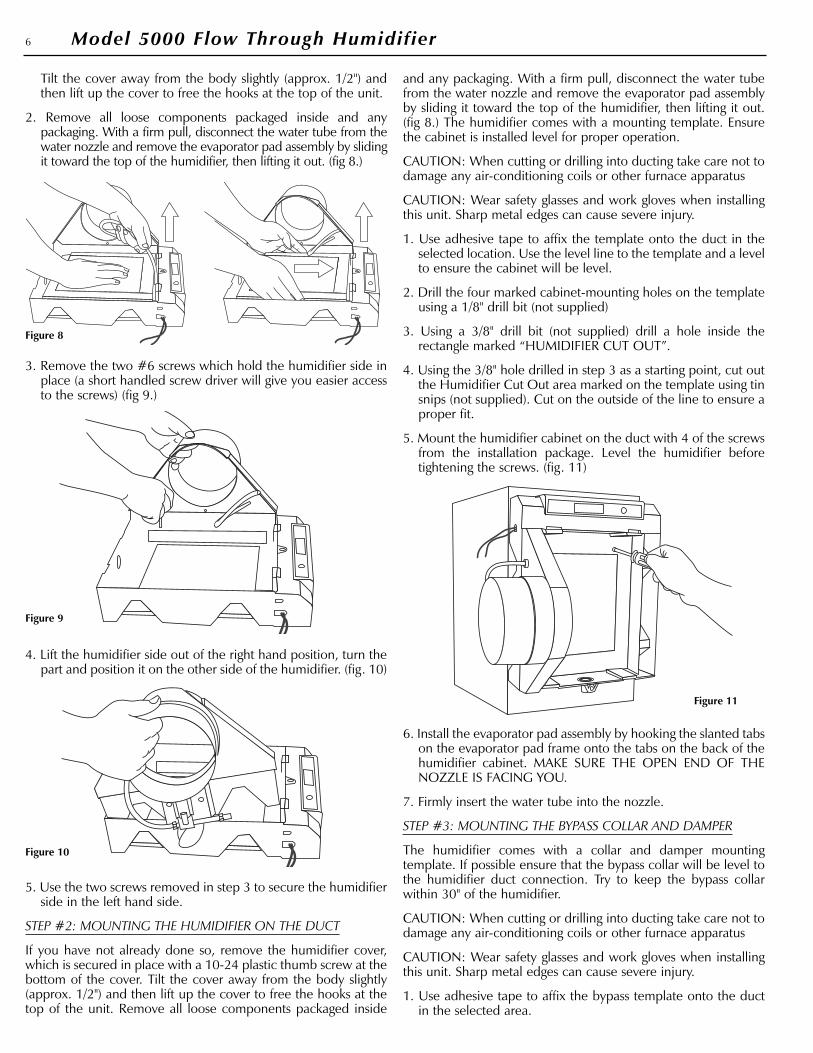
Tilt the cover away from the body slightly (approx. 1/2") andthen lift up the cover to free the hooks at the top of the unit.
2. Remove all loose components packaged inside and anypackaging. With a firm pull, disconnect the water tube from thewater nozzle and remove the evaporator pad assembly by slidingit toward the top of the humidifier, then lifting it out. (fig 8.)
3. Remove the two #6 screws which hold the humidifier side inplace (a short handled screw driver will give you easier accessto the screws) (fig 9.)
4. Lift the humidifier side out of the right hand position, turn thepart and position it on the other side of the humidifier. (fig. 10)
5. Use the two screws removed in step 3 to secure the humidifierside in the left hand side.
STEP #2: MOUNTING THE HUMIDIFIER ON THE DUCT
If you have not already done so, remove the humidifier cover,which is secured in place with a 10-24 plastic thumb screw at thebottom of the cover. Tilt the cover away from the body slightly(approx. 1/2") and then lift up the cover to free the hooks at thetop of the unit. Remove all loose components packaged inside
and any packaging. With a firm pull, disconnect the water tubefrom the water nozzle and remove the evaporator pad assemblyby sliding it toward the top of the humidifier, then lifting it out.(fig 8.) The humidifier comes with a mounting template. Ensurethe cabinet is installed level for proper operation.
CAUTION: When cutting or drilling into ducting take care not todamage any air-conditioning coils or other furnace apparatus
CAUTION: Wear safety glasses and work gloves when installingthis unit. Sharp metal edges can cause severe injury.
1. Use adhesive tape to affix the template onto the duct in theselected location. Use the level line to the template and a levelto ensure the cabinet will be level.
2. Drill the four marked cabinet-mounting holes on the templateusing a 1/8" drill bit (not supplied)
3. Using a 3/8" drill bit (not supplied) drill a hole inside therectangle marked “HUMIDIFIER CUT OUT”.
4. Using the 3/8" hole drilled in step 3 as a starting point, cut outthe Humidifier Cut Out area marked on the template using tinsnips (not supplied). Cut on the outside of the line to ensure aproper fit.
5. Mount the humidifier cabinet on the duct with 4 of the screwsfrom the installation package. Level the humidifier beforetightening the screws. (fig. 11)
6. Install the evaporator pad assembly by hooking the slanted tabson the evaporator pad frame onto the tabs on the back of thehumidifier cabinet. MAKE SURE THE OPEN END OF THENOZZLE IS FACING YOU.
7. Firmly insert the water tube into the nozzle.
STEP #3: MOUNTING THE BYPASS COLLAR AND DAMPER
The humidifier comes with a collar and damper mountingtemplate. If possible ensure that the bypass collar will be level tothe humidifier duct connection. Try to keep the bypass collarwithin 30" of the humidifier.
CAUTION: When cutting or drilling into ducting take care not todamage any air-conditioning coils or other furnace apparatus
CAUTION: Wear safety glasses and work gloves when installingthis unit. Sharp metal edges can cause severe injury.
1. Use adhesive tape to affix the bypass template onto the ductin the selected area.
6 Model 5000 Flow Through Humidifier
Figure 8
Figure 9
Figure 10
Figure 11

2. Drill three marked bypass collar mounting holes on thetemplate using a 1/8" drill bit (not supplied)
3. Using a 3/8" drill by (not supplied) drill a hole inside thecircular area marked collar cut out.
4. Using the 3/8" hole drilled in step 3 as a starting point cut outthe Collar Cut Out area marked on the template using tin snips(not supplied)
5. Mount the bypass collar and damper (fig. 12) using theremaining three screws from the installation package. The airdamper should be mounted in the open position. The topscrew secures the damper.
6. Slide one of the 6" spring clamps supplied over one end of thebypass tube. Slide this same end of the bypass tube over theflange of the collar and secure it with the spring clamp.
7. Slide the other 6" spring clamp over the other end of thebypass tube. Slide this end of the bypass tube onto thehumidifier and secure it with the spring clamp.
8. Ensure the bypass is pulled tight and that any ripples are keptto a minimum and no sagging is occurring. Cut any excessbypass tube off if necessary using tin snips (not supplied).
• INSTALLATION TIP: If replacing an existing humidifierwhich has been installed on your furnace you may beable to use the existing cut-outs, however replace thecomponents, bypass collar and damper and bypasstubing. The majority of furnace humidifiers use 6"ducting for bypass. The cutout for the humidifier willmore than likely be different. If replacing a drum stylethe cutout will not be big enough, and if replacing an oldflow through you may have to first install a separatemetal plate (not supplied) to cover the existing hole as itmay be too big. Before you mount the separate metalplate (not supplied) attach the humidifier cabinettemplate to it and drill all necessary holes and make therequired cutouts. Keep in mind the points listed aboveabout length and level of ducting; it maybe best to coverall existing holes and start fresh.
STEP #4: WATER SUPPLY AND DRAINAGE CONNECTION
WARNING: Make sure the evaporator pad is installed correctlyBEFORE you make the water connections.
1. SAND BOTH ENDS (fig 13) of the water supply tube. FAILURETO DO SO MAY RESULT IN LEAKS.
2. Prepare the end (fig 14) of the 1/4" tubing for water connectionto the humidifier (All required hardware supplied in thesaddle-valve kit in the installation package).
3. Make the tube connection to the humidifier using anadjustable wrench (not supplied) to tighten the nut. (fig 15)
4. Select the most convenient location for connecting the self-piercing needle valve on a cold water pipe. Connect the needlevalve as shown (fig 16). The hardware shown is supplied in theneedle-valve kit. Once the the valve is connected to a pipe asshown, TURN THE VALVE CLOSED ALL THE WAY, and thenopen so water can flow to the humidifier. Check all fittings forleaks and tighten/repair if necessary.
7Model 5000 Flow Through Humidifier
Figure 12
Figure 13
Figure 15
Figure 14
Brass nut Plastic ferrule
Plastic water tube
Brassinsert
Figure 16Brass nut
Plasticferrule
Plastic water tube
Brass insert

5. YOU MUST RUN ADRAINAGE TUBE FROMTHIS UNIT. Select aconvenient location forrunning the 1/2" drainagetube, 15 ft supplied.Before you connect thetubing to the drain fittingon the bottom of theunit, slip the 1/2" hoseclamp (supplied) over thetubing (fig 17). Push thetubing over the fitting andsecure in place with thehose clamp.
CAUTION: Drain tubingmust not kink or comeinto contact with sharpedges or hot surfaces.
STEP #5: ELECTRICAL INSTALLATION
The humidistat supplied with the Model 5000 Humidifier can beeither duct or wall mounted. Duct mounting the humidistat is theeasiest installation. A wall mount provides more convenient controlof the humidifier and depending on your heating/ventilationsystem may provide a more accurate indication of the relativehumidity level in your home. When wall mounting the humidistatyou should choose a central location (close to the furnacethermostat) and you may be required to purchase extra low voltagewire to run back to the humidifier. 20 ga will be sufficient.
DUCTING MOUNTING THE HUMIDISTAT AND POWER CONNECTION TO THE HUMIDIFIER
The humidistat is packaged at the factory ready for wallmounting. You will have to convert it to duct mounting. Refer tofig. 18, when duct mounting the humidistat must be locatedupstream (approx 6”) from the humidifier or bypass tube on thereturn duct. Select a convenient location to mount the humidistaton the return duct. The unit comes with a humidistat mountingtemplate. THIS TEMPLATE IS FOR DUCT MOUNTING THEHUMIDISTAT ONLY.
1. Drill the 4 marked humidistat mounting holes on the templateusing the 5/64” drill bit (not supplied)
2. Using a 3/8” drill bit (not supplied) drill a hole inside therectangle marked Humidistat Cut Out.
3. Using the 3/8” hole drilled in step 2 as a starting point cut outthe Humidistat Cut Out area using tin snips (not supplied)
4. Locate the humidifier terminal panel on the side of thehumidifier cabinet, behind the bypass tube. Connect the twoends of the transformer lead wires to the humidifier terminalsmarked “24 VAC IN”. (fig 19)
5. Run the transformer leadwires from the humidifier to thecenter of the hole you createdin step 3. Note the length of thewire from the humidifier to thispoint, and add approximately 2more inches to this length. Atthis point on the wire, carefullycut the insulation between theconductors and separate themapprox 3” (fig 20)
6. Cut on the conductors andstrip (approx 3/4") the insulationfrom both ends (fig 21).
7. From the humidistat assemblyincluded with your unit removethe humidistat. Gently pull offthe knob and label, and removethe humidistat cover (fig 22 )
8. Remove the humidistat control from the base plate by undoingthe two screws holding it in place.
9. In the duct mounting application the base plate is used as thefront cover, reattach the humidistat control to the base plate(fig 18).
10. Using the two 90-degree terminals included with thehumidistat kit, attach the two stripped wire ends of thetransformer leads that you cut in step 6 to the humidistatterminals.
11. Mount the humidistat assembly into the duct cut out made instep 3. Secure in place with four screws provided in thehumidistat kit (fig 17).
12. Remove the paper backing from the humidistat label andapply onto the face plate. Install the knob onto the humidistatcontrol shaft.
WALL MOUNTING THE HUMIDISTAT AND POWER CONNECTION TO THE HUMIDIFIER
CAUTION: When cutting or drilling in a wall take care not to hitany of home’s electrical or other utilities.
1. Select a central location in the home at eye level on an insidewall. The best place is next to the furnace’s thermostat.
2. Drill a small hole to fish low voltage wire (not supplied) out ofand leave approximately 6” of wire leads outside of the holefor connection to the humidistat. Guide the other end of thelow voltage wire to the humidifier on the furnace.
3. Locate the humidifier terminal panel on the side of the
8 Model 5000 Flow Through Humidifier
Figure 17
Figure 19
Figure 20 Figure 21
Figure 18
Label
Base
Humidistat
Low VoltageWire

humidifier cabinet, behind the bypass tube. Connect the twoends of the transformer leads to the humidifier terminalsmarked “24 VAC IN”
4. At any point along the transformer leads (most convenientlocation to connect the transformer low voltage wire to thehumidistat low voltage wire) carefully cut the insulationbetween the two conductors and separate them approx 3” (fig20).
5. Cut one of the conductors and strip (approx. 3/4”) theinsulation from both ends ( fig 21).
6. Using wire nuts (not supplied), connect the two stripped endsof the low voltage wire leads from the humidistat to the twoends of the stripped transformer leads prepared in step 5.
7. Returning to the humidistat location, remove the cover platefrom the humidistat. Feed the 6” of low voltage wire throughthe 3/8” hole in the humidistat base plate. Mount thehumidistat to the wall using four screws provided in thehumidistat kit (fig 22).
8. Using the two 90-degree wire terminals (included in thehumidistat kit) connect the end of the low voltage wire to thehumidistat terminals.
9. Replace the cover. Remove the paper backing from thehumidistat label, and apply to the face of the cover. Install theknob onto the humidistat control shaft.
CHECKING THE ELECTRICAL CONNECTION, DUCT MOUNT OR WALL MOUNT HUMIDISTAT.
Once the wiring is complete you should have all the componentswired in series (a continuous loop) as shown in fig. 23. Use theinsulated staples included in you installation package to secureany loose wiring.
STEP #6: TESTING THE INSTALLATION
If you have not already replace the front cover of the humidifierand secure in place using the plastic thumb screw.
1. Make sure all water connections are secure and do not leak. Also,ensure that all components are secure and installed correctly.
2. Plug in the 24-Volt transformer into a constant 120-Volt powersource (an outlet which cannot be shut off via a wall switch).
3. Turn up the humidistat to the maximum setting 50% +. Thisensures the humidistat is calling for humidity. If the humidistatis not calling for humidity at the BEGINNING of the furnacecycle the humidifier will not turn on, if you turn up thehumidistat in the middle of the furnace cycle the humidifierwill wait until the NEXT cycle to turn on.
4. Turn on the power to your furnace and turn up the thermostatso that the furnace cycles on in heating mode.
• OPERATING TIP: Most furnaces will take a fewminutes to allow heat to build up before the furnace fanwill run. The “HUMIDISENSE” control contained in thehumidifier will wait until it senses your furnace fanblowing hot air. If only your furnace fan is running theunit should not turn on. The “HUMIDISENSE” will notturn the humidifier on until is senses a temperature riseof 4°C and the air temperature is over 30°C. This ensuresthe efficient use of water.
5. Depending on your furnace type the unit should turn onwithin approx 60 seconds of the furnace entering theHEATING cycle. You will know because the green“HUMIDISENSE” LED on the front of unit will turn on (fig 24.)If the unit does not turn on refer to the trouble shootingsection in the Maintenance Guide.
6. Once the unit has been running for approx 3-4 minutes youwill see a small amount of water trickling out of the drain tube.If the unit has turned on and the green light is on but no wateris trickling refer to the trouble shooting section in theMaintenance Guide.
• OPERATING TIP: In order to ensure efficient water use,ensure water will not blow off the evaporator, and toprotect the humidifier’s solenoid valve there is an orificefitting installed on the inlet of the solenoid valve. Thisfitting restricts the amount of water flowing to the unit,which will vary depending on your house’s waterpressure. On average this fitting will allow approx 300-600 ml of water to flow in 5 minutes of humidifieroperation.
9Model 5000 Flow Through Humidifier
Figure 23
Figure 22
GreenHumidisense
LED
Figure 24
Humidistat Humidifier
120VElectricSource
24VTransformer
Cover
Humidistat
Label
Base
7. After about 5 minutes of running turn your thermostat downso the furnace cycles off. IT IS IMPORTANT TO ALLOW THEFURNACE TO CYCLE OFF VIA THE THERMOSTAT AND NOTTHE MAIN FURNACE SWITCH, AS ALL FURNACES WILLRUN A COOL DOWN TO ALLOW HEAT TO CIRCULATEOUT OF THE FURNACE HEATING CHAMBER. Thehumidifier will sense the temperature drop and shut off (thiswill occur depending on your furnace, from 60 seconds beforethe furnace shuts of to 60 seconds after the furnace shuts off.)You will know the humidifier has shut off because the green“HUMIDISENSE” LED on the front of the humidifier will shutoff. (fig. 24) The off cycle of the “HUMIDISENSE” CONTROLIS ADJUSTABLE. See section “CUSTOMIZING HUMIDISENSETO YOUR FURNACE” below if the humidifier does not shutoff with your furnace.
• OPERATING TIP: Most furnaces will take anywherefrom 30 seconds to 2 minutes to complete a off cycle.First the furnace will sense that the thermostat is satisfiedthen the furnace burner will shut off. The furnace fan willcontinue to run (the amount of time depending on howyour furnace is set up) this allows the heat to circulateout of the furnace heating chamber and assures efficientuse of heating fuel.
HUMIDIFIER OPERATION
CUSTOMIZING HUMIDISENSE TO YOUR FURNACE
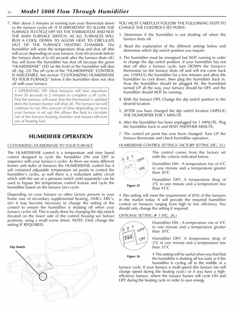
The HUMIDISENSE control is a temperature and time basedcontrol designed to cycle the humidifier ON and OFF insequence with your furnace’s cycles. As there are many differenthomes and styles of furnaces the HUMIDISENSE control has 4self contained adjustable temperature set points to control thehumidifier’s cycles, as well there is a redundant safety circuitwhich with the use of a pressure switch (sold separately) can beused to bypass the temperature control feature and cycle thehumidifier based on the furnace fan’s cycle.
Depending on your furnace or other factors present in yourhome (use of secondary supplemental heating, HVR’s, ERV’s,etc) it may become necessary to change the setting of thecontrol to ensure the humidifier is shutting off when yourfurnace cycles off. This is easily done by changing the dip switch(located on the lower side of the control housing see below)positions, using a small screw driver. NOTE: Only change thesetting IF REQUIRED.
YOU MUST CAREFULLY FOLLOW THE FOLLOWING STEPS TOCHANGE THE CONTROL’S SET POINT:
1. Determine if the humidifier is not shutting off when thefurnace shuts off
2. Read the explanation of the different settings below anddetermine which dip switch position you require.
3. The humidifier must be energized but NOT running in orderto change the dip switch position. If your humidifier has notshut off after a furnace cycle, turn DOWN the furnace’sthermostat (so the furnace shuts off and will not come backon). UNPLUG the humidifier for a few minutes and allow thehumidifier to cool down, then plug the humidifier back in.Now the humidifier should be plugged IN, the humidistatturned UP all the way, your furnace should be OFF, and thehumidifier should NOT be running.
4. With the furnace OFF, Change the dip switch position to thedesired location.
5. AFTER you have changed the dip switch location UNPLUGTHE HUMIDIFIER FOR 1 MINUTE.
6. After the humidifier has been unplugged for 1 MINUTE, Plugthe humidifier back in and WAIT ANOTHER MINUTE.
7. The control set point has now been changed. Turn UP thefurnace thermostat and check humidifier operation.
HUMIDISENSE CONTROL SETTINGS: FACTORY SETTING (FIG. 25.)
The control comes from the factory setwith the criteria indicated below.
Humidifier ON : A temperature rise of 4°Cin one minute and a temperature greaterthan 30°C
Humidifier OFF: A temperature drop of2°C in one minute and a temperature lessthan 45°C
• This setting will meet the requirement of 85% of the furnacesin the market today. It will provide the required humidifiercontrol on furnaces ranging from high to low efficiency. Youshould only change the setting if required.
OPTIONAL SETTING # 1 (FIG. 26.)
Humidifier ON : A temperature rise of 4°Cin one minute and a temperature greaterthan 30°C
Humidifier OFF: A temperature drop of2°C in one minute and a temperature lessthan 35°C
• This setting will be useful when you find thatthe humidifier is shutting off too early or if thehumidifier is cycling off in the middle of a
furnace cycle. If your furnace is multi-speed (the furnace fan willchange speed during the heating cycle.) or if you have a high-efficiency furnace, where the furnace burner will cycle ON andOFF during the heating cycle in order to save energy.
10 Model 5000 Flow Through Humidifier
Figure 25
Figure 26
Dip Switch

OPTIONAL SETTING # 2 (FIG27.)
Humidifier ON : A temperature rise of 4°Cin one minute and a temperature greaterthan 30°C
Humidifier OFF: A temperature drop of2°C in one minute and a temperature lessthan 55°C
• This setting will be useful when you findthe humidifier is not turning off when yourfurnace has cycled off. Typically this will
occur because the furnace’s cool down cycle is short and thefurnace is shutting off when there is still hot air circulating throughthe ducts. As well this will be seen when the furnace is located inan enclosed space and as a result the ambient temperature is high.
OPTIONAL SETTING # 3 (FIG. 28.)
Humidifier ON : A temperature rise of 4°Cin one minute and a temperature greaterthan 30°C
Humidifier OFF: A temperature drop of2°C in one minute and a temperature lessthan 65°C
• This setting will be used when option # 2(55°C off temp) does not work. You will findthis when a furnace does not have a cool
down cycle at all, on older model furnaces. This could beoccurring when the furnace is older and has short off cycles or ifthe furnace is located in a tight enclosed space and the ambienttemperature is very high.
• OPERATING TIP: Depending on the type of furnace andinstallation, you may notice that after the humidifier hasshut off and the furnace shuts off the humidifier will turnback on. This is occurring because the control is sensingresidual heat from the heat exchanger after the furnace hasshut off. If you are experiencing this you should change thecontrol setting until the problem is resolved. Thetemperature at which your furnace shuts off is too close tothe control’s OFF temperature. It may be beneficial to havethe control set to the higher OFF temperature (55°C or65°C). However it is important to note ONLY CHANGETHE CONTROL SETTING IF NECESSARY.
REDUNDANT SAFETY CIRCUIT SETTING – PRESSURE SWITCH CONTROL (NOT SUPPLIED) (FIG. 29)
Humidifier ON: When pressure switchsenses air-flow in the furnace duct
Humidifier OFF: When pressure switchsenses no air-flow in the duct.
• This setting can be used if for some reasonthe above 4 different control setting fail toshut off the humidifier. This is more thanlikely occurring as a result of a non-standardheating system, some sort of supplement
heating, improper humidifier installation, improper furnaceoperation, or for some other unforeseen circumstance. Thisoption may also be used if for some reason the humidifier will notturn on, this could be occurring because the furnace is notproviding enough heat or it is not providing the requiredtemperature rise fast enough. All four of the above control setting
have the same ON temperature requirements. This is ensuring anefficient use of water as there is a minimum air temperature toefficiently evaporate water. As well if for some reason you wish tobypass the temperature feature and have the humidifier operatewhen fan operates you may choose this option. This optionrequires the purchase and installation of a separate pressureswitch (fig 30). Installation instructions for the pressure switch areincluded with the kit.
CONTROLLING THE HUMIDITY LEVELAND HUMIDIFIER OPERATION
HUMIDIFIER START UP
When you first plug in the 24 Volt transformer and turn on yourhumidifier you may hear a click. This is the power getting to thecontrol’s relay. As well if you adjust the humidistat UP or DOWNand past the sensed humidity level you may hear the control’srelay clicking. This is normal as the humidistat is just an ON/OFFswitch, every time the humidistat is turned DOWN the power iscut to the HUMIDISENSE control.
When starting up the humidifier for operation:
1. Make sure the transformer is plugged in and the water supplyis turned on.
2. Turn the humidistat up high, so it is calling for humidity.
3. Turn your furnace thermostat UP so the furnace cycles ON.
4. Once the HUMIDISENSE control senses heat the humidifier willturn ON. You will know because the green “HUMIDISENSE”LED (fig. 24) on the front of the humidifier will turn ON.
5. After a few moments you should hear water trickling throughthe drain.
6. After your furnace has completed the heating cycle and shutoff (by the thermostat) the humidifier will cycle OFF. You willknow because the green “HUMIDISENSE” LED (fig. 24) on thefront of the humidifier will turn OFF
CONTROLLING THE HUMIDITY LEVEL
A humidistat is supplied with this humidifier to control theamount of moisture added to the air in your home. It will sense
11Model 5000 Flow Through Humidifier
Figure 27
Figure 28
Figure 29
Figure 30Pressure Switch

the relative humidity level in the air and work as the mainON/OFF switch to control the humidifier, regardless of whetheryour furnace is on or not.
At the beginning of the heating season it may take sometime tobuild up the relative humidity level in your home to the desiredlevel. For the first few weeks turn the humidistat up high to ensurethe humidifier will turn on with every furnace cycle; after you feelthat you have achieved the desired relative humidity level turn thehumidistat down until it cycles the humidifier OFF. The humidifierwill then work to maintain the relative humidity at that level.
ACHIEVING AND MAINTAINING A HUMIDITY LEVEL
Outside conditions are the primary factor affecting the humiditylevel in your home; the colder it gets outside the less moisture theoutside air will have, your home brings in that outside air and thehumidifier will work to add moisture to it. As outside conditionschange the humidity level in your home will change as well.Other factors which will affect humidity levels in the homeinclude how many air-changes are occurring, the amount ofpeople occupying the home, air leaks, the use of showers,exhaust fans, HRV’s, and the use of a fireplaces or wood stoves.For more information on achieving a humidity level and ormaximizing the output of the humidifier please see theMaintenance and Trouble Shooting Guide.
SAFELY OPERATING A FURNACE HUMIDIFIER
Proper control of the relative humidity level in the home is key toensuring good IAQ (Indoor Air Quality) for your home as well asprotecting against moisture damage.
Although a relative humidity environment of 45-50% may bedesirable, setting your humidistat at that point when outside airtemperatures are below 30°F can cause condensation onwindows and walls. Continued condensation for extendedperiods of time may result in structural damage. Use the chartbelow as a guide for maximum relative humidity settings atdifferent outdoor air temperatures.
If condensation continues to form on windows at these settingsreduce the humidistat setting by successive 5% increments. Aftereach reduction in setting allow 6 hours for equilibrium to bereached before readjustment.
If condensation is consistently forming on your windows or if therelative humidity level being sensed by the humidistat is consistentlydifferent than the relative humidity level in the home then you maywant to consider changing the location where the humidistat ismounted. If duct mounted, move the humidistat to a centrallocation, near the furnace thermostat. If after moving the humidistatthe condition persists turn OFF the water supply at the needle valve,turn the humidistat off and consult a qualified HVAC service person.
When your house is unoccupied for longer than 3 days duringthe winter months always set the humidistat down to 15% so thatsevere weather during you absence will not result incondensation which might cause damage in your home.
BYPASS AIR ADJUSTMENT, SUMMERSHUTDOWN, AND YEARLY MAINTENANCE
BYPASS AIR ADJUSTMENT
Sometimes there can be a static pressure differential that maycause an excess of air to flow through the bypass tube, causingless airflow through the distant heat outlets in the house. It mayalso blow water off the evaporator bad. In either case the airdamper installed with the bypass collar should by graduallyclosed until the condition is corrected. To close the damperloosen the top screw and lift up on the damper and turn closedto the desired position. Damper adjustment is another way ofadjusting the amount of humidity being added to the house (theless air bypassed the less humidity will be added.)
SUMMER SHUT DOWN
At the end of the heating season complete the following steps.
1. Turn the humidistat off.
2. Unplug the transformer.
3. Close off the water supply at the saddle valve.
4. Close the bypass damper.
YEARLY MAINTENANCE AND WINTER START UP
For detailed recommended maintenance schedule refer to theMaintenance and Trouble Shooting Guide.
At the beginning of the heating season complete the following steps.
1. Inspect the water supply tube, water drainage tube, andElectrical wiring replace if required
2. Plug in the transformer.
3. Turn on the water supply at the saddle valve and check forany leaks.
4. Open the bypass damper.
5. Test the operation of the humidifier and check for any leaksand complete any necessary repairs.
OUT SIDE AIR TEMPERATURE MAXIMUM RELATIVE HUMIDITY SETTING
-20°F /-30°C 15%
-10°F /-25°C 20%
0°F / -20°C 25%
+10°F/-10°C 30%
+20°F/-5°C 35%
ABOVE +20°F/0°C 40%
12 Model 5000 Flow Through Humidifier