Embed Size (px)
Citation preview

CONTENTS
GENERAL INFORMATION . . . . . . . . . . . . . . . . . . . 3
SPECIFIC UNIT INFORMATION . . . . . . . . . . . . . . . 4
UPFLOW MODELS . . . . . . . . . . . . . . . . . . . . . . . . . 8
DOWNFLOW / HORIZONTAL MODELS - HORIZONTAL APPLICATION . . . . . . . . . . . . . . . . 11
GAS PIPING . . . . . . . . . . . . . . . . . . . . . . . . . . . . . . 12
ELECTRICAL POWER CONNECTION . . . . . . . . . 13
ELECTRICAL CONTROL CONNECTIONS . . . . . . 14
COMBUSTION AIR AND VENT SYSTEM . . . . . . . 15
HORIZONTAL VENT APPLICATIONS . . . . . . . . . 24
CONDENSATE PIPING . . . . . . . . . . . . . . . . . . . . . 24
SAFETY CONTROLS . . . . . . . . . . . . . . . . . . . . . . . 26
START-UP AND ADJUSTMENTS . . . . . . . . . . . . . 27
FURNACE ACCESSORIES . . . . . . . . . . . . . . . . . . 32
AIRFLOW DATA - UPFLOW . . . . . . . . . . . . . . . . . 33
AIRFLOW DATA - DOWNFLOW/HORIZONTAL . 33
OPERATION AND MAINTENANCE . . . . . . . . . . . 34
TROUBLESHOOTING . . . . . . . . . . . . . . . . . . . . . . 37
FURNACE CONTROL DIAGNOSTICS . . . . . . . . . 37
WIRING DIAGRAM - UPFLOW MODELS . . . . . . . 39
WIRING DIAGRAM - DOWNFLOW/HORIZONTAL 40
INSTALLATION INSTRUCTION
CAUTION: READ ALL SAFETY GUIDES BEFORE YOU START TO INSTALL YOUR FURNACE.
SAVE THIS MANUAL
HIGH EFFICIENCY
GAS-FIRED FURNACES TUBULAR
HEAT EXCHANGER SERIES
UPFLOW MODELS: P*UR / FG9-UP / G9T-UP40 - 140 MBH INPUT
DOWNFLOW/HORIZONTAL MODELS: P*DH / FG9-DH / G9T-DH40 - 120 MBH INPUT
035-14370-000 REV A (899) Form 650.75-N4U

650.75-N4U 035-14370-000
2 Unitary Products Group
TABLE OF CONTENTS
GENERAL INFORMATION . . . . . . . . . . . . . . . . . . . . . . . . . 3DESCRIPTION . . . . . . . . . . . . . . . . . . . . . . . . . . . . . . . . 3INSPECTION . . . . . . . . . . . . . . . . . . . . . . . . . . . . . . . . . . 3NOTES, CAUTIONS & WARNINGS . . . . . . . . . . . . . . . . 3VENT SAFETY CHECK PROCEDURE . . . . . . . . . . . . . 3
SPECIFIC UNIT INFORMATION . . . . . . . . . . . . . . . . . . . . . 4LIMITATIONS & LOCATION . . . . . . . . . . . . . . . . . . . . . . 4CLEARANCES FOR ACCESS . . . . . . . . . . . . . . . . . . . . 4CLEARANCES TO COMBUSTIBLES . . . . . . . . . . . . . . . 5BELOW FREEZING LOCATIONS . . . . . . . . . . . . . . . . . . 5DUCTWORK . . . . . . . . . . . . . . . . . . . . . . . . . . . . . . . . . . 8
UPFLOW MODELS . . . . . . . . . . . . . . . . . . . . . . . . . . . . . . . 8SUPPLY PLENUM CONNECTION . . . . . . . . . . . . . . . . . 8RETURN DUCT CONNECTION . . . . . . . . . . . . . . . . . . . 9UPFLOW FILTER INSTALLATION . . . . . . . . . . . . . . . . . 9
INTERNAL INSTALLATION . . . . . . . . . . . . . . . . . . . . . . . . . 9SIDE RETURN - EXTERNAL FILTER . . . . . . . . . . . . . . . . . 9BOTTOM RETURN . . . . . . . . . . . . . . . . . . . . . . . . . . . . . 10
DOWNFLOW/HORIZONTAL MODELSDOWNFLOW APPLICATION . . . . . . . . . . . . . . . . . . . . 10DOWNFLOW FILTERS . . . . . . . . . . . . . . . . . . . . . . . . . 10SUPPLY AIR DUCTS . . . . . . . . . . . . . . . . . . . . . . . . . . 11
DOWNFLOW / HORIZONTAL MODELS - HORIZONTAL APPLICATION . . . . . . . . . . . . . . . . . . . . . . . . . . . . . . . . . . 11
HORIZONTAL FILTERS. . . . . . . . . . . . . . . . . . . . . . . . 11ATTIC INSTALLATION . . . . . . . . . . . . . . . . . . . . . . . . . 11CRAWL SPACE INSTALLATION . . . . . . . . . . . . . . . . . 12
GAS PIPING . . . . . . . . . . . . . . . . . . . . . . . . . . . . . . . . . . . 12
ELECTRICAL POWER CONNECTION . . . . . . . . . . . . . . . 13
ELECTRICAL CONTROL CONNECTIONS . . . . . . . . . . . 14
COMBUSTION AIR AND VENT SYSTEM . . . . . . . . . . . . 15METHOD ONE: TWO PIPE SEALED COMBUSTION AIR & VENT SYSTEM . . . . . . . . . . . . . . . . . . . . . . . . . . . . . 15
COMBUSTION AIR INTAKE/VENT CONNECTIONS 15COMBUSTION AIR/VENT PIPE SIZING . . . . . . . . . . 16VENT TERMINATION (2-PIPE). . . . . . . . . . . . . . . . . 16VENT CLEARANCES (2-PIPE) U.S. ONLY . . . . . . . 17VENTING MULTIPLE UNITS. . . . . . . . . . . . . . . . . . . 17PIPING ASSEMBLY . . . . . . . . . . . . . . . . . . . . . . . . . . 18
METHOD TWO: ONE PIPE SYSTEM . . . . . . . . . . . . . . 19COMBUSTION AIR . . . . . . . . . . . . . . . . . . . . . . . . . . . 19AIR SOURCE FROM OUTDOORS - . . . . . . . . . . . . . . . . . . 20SPECIAL COMBUSTION AND VENTILATION CONSIDERATIONS . . . . . . . . . . . . . . . . . . . . . . . . . . . . . 20SPECIALLY ENGINEERED INSTALLATIONS . . . . . . . . . . . . 20COMBUSTION AIR QUALITY . . . . . . . . . . . . . . . . . . . . . . 20VENT PIPE SIZING (1-PIPE SYSTEM) . . . . . . . . . . . 21VENT TERMINATION (1-PIPE SYSTEM) . . . . . . . . . 21VENT TERMINAL LOCATION CLEARANCES . . . . . 21PIPING ASSEMBLY . . . . . . . . . . . . . . . . . . . . . . . . . . 23
METHOD THREE: TWO PIPE SYSTEM USING COM-BUSTION AIR FROM A VENTILATED ATTIC SPACE . 23
COMBUSTION AIR INTAKE . . . . . . . . . . . . . . . . . . . 23COMBUSTION AIR TERMINATION . . . . . . . . . . . . . 23COMBUSTION AIR REQUIREMENTS . . . . . . . . . . . . 23VENT PIPE . . . . . . . . . . . . . . . . . . . . . . . . . . . . . . . . . 23VENT TERMINATION . . . . . . . . . . . . . . . . . . . . . . . . . 24
HORIZONTAL VENT APPLICATIONS . . . . . . . . . . . . . . . 24
CONDENSATE PIPING 24CONVERSION FOR HORIZONTAL APPLICATIONS . . . . . . . 25
SAFETY CONTROLS . . . . . . . . . . . . . . . . . . . . . . . . . . . . 26LIMIT CONTROL . . . . . . . . . . . . . . . . . . . . . . . . . . . . . . 27AUXILIARY LIMIT CONTROLS . . . . . . . . . . . . . . . . . . . . . 27
START-UP AND ADJUSTMENTS . . . . . . . . . . . . . . . . . . 27IGNITION SYSTEM SEQUENCE . . . . . . . . . . . . . . . . . 27GAS VALVE OPERATION . . . . . . . . . . . . . . . . . . . . . . 28CHECKING GAS INPUT (NATURAL GAS) . . . . . . . . . 28ADJUSTMENT OF MANIFOLD GAS PRESSURE . . . . 29ADJUSTMENT OF TEMPERATURE RISE . . . . . . . . . . 30ADJUSTMENT OF FAN-OFF CONTROL SETTINGS . 30ACCESSORY CONNECTIONS . . . . . . . . . . . . . . . . . . 31
ELECTRONIC AIR CLEANER CONNECTION . . . . . . . . . . . 31HUMIDIFIER CONNECTION . . . . . . . . . . . . . . . . . . . . . . . 31
FURNACE ACCESSORIES . . . . . . . . . . . . . . . . . . . . . . . 32
AIRFLOW DATA - UPFLOW . . . . . . . . . . . . . . . . . . . . . . 33
AIRFLOW DATA - DOWNFLOW/HORIZONTAL . . . . . . . 33
OPERATION AND MAINTENANCE . . . . . . . . . . . . . . . . . 34SEQUENCE OF OPERATION. . . . . . . . . . . . . . . . . . . . 34CONTINUOUS BLOWER . . . . . . . . . . . . . . . . . . . . . . . 34INTERMITTENT BLOWER - COOLING . . . . . . . . . . . . 34HEATING CYCLE . . . . . . . . . . . . . . . . . . . . . . . . . . . . . 34
HOT SURFACE IGNITION SYSTEM . . . . . . . . . . . . . . . . . 34MAINTENANCE . . . . . . . . . . . . . . . . . . . . . . . . . . . . . . 35
AIR FILTERS . . . . . . . . . . . . . . . . . . . . . . . . . . . . . . . . . 35FILTER REMOVAL - UPFLOW MODELS . . . . . . . . . . . . . . 35FILTER REMOVAL - DOWNFLOW MODELS . . . . . . . . . . . . 35HORIZONTAL APPLICATIONS . . . . . . . . . . . . . . . . . . . . . 36LUBRICATION . . . . . . . . . . . . . . . . . . . . . . . . . . . . . . . . 36BLOWER CARE . . . . . . . . . . . . . . . . . . . . . . . . . . . . . . . 36BURNER REMOVAL/CLEANING . . . . . . . . . . . . . . . . . . . . 36CLEANING THE HEAT EXCHANGER . . . . . . . . . . . . . . . . . 36CLEANING THE SECONDARY HEAT EXCHANGER . . . . . . . 37VENT/AIR INTAKE . . . . . . . . . . . . . . . . . . . . . . . . . . . . . 37
TROUBLESHOOTING . . . . . . . . . . . . . . . . . . . . . . . . . . . 37
FURNACE CONTROL DIAGNOSTICS . . . . . . . . . . . . . . 37
WIRING DIAGRAM - UPFLOW MODELS. . . . . . . . . . . . . 39
WIRING DIAGRAM - DOWNFLOW/HORIZONTAL . . . . . 40
035-14370-000 650.75-N4U
Unitary Products Group 3
GENERAL INFORMATION
DESCRIPTION
This Category IV, dual certified, direct vent and 1-pipe ventfurnace is designed for residential or commercial installationin a basement, closet, recreation room, garage or other loca-tion provided space temperature is 32°F or higher. For appli-cations in below freezing locations, refer to “BELOWFREEZING LOCATIONS” section on page 5.
INSPECTION
As soon as a unit is received, it should be inspected for possi-ble damage during transit. If damage is evident, the extent ofthe damage should be noted on the carrier's freight bill. Aseparate request for inspection by the carrier's agent shouldbe made in writing. Also, before installation the unit should bechecked for screws or bolts which may have loosened in tran-sit. There are no shipping or spacer brackets which need tobe removed.
NOTES, CAUTIONS & WARNINGS
The installer should pay particular attention to the words:
NOTE, CAUTION and WARNING. NOTES are intended toclarify or make the installation easier. CAUTIONS are givento prevent equipment damage. WARNINGS are given to alertthe installer that personal injury and/or equipment or propertydamage may occur if installation procedures are not handledproperly.
VENT SAFETY CHECK PROCEDURE
If this furnace is replacing a common-vented furnace, it maybe necessary to resize the existing vent line and chimney to
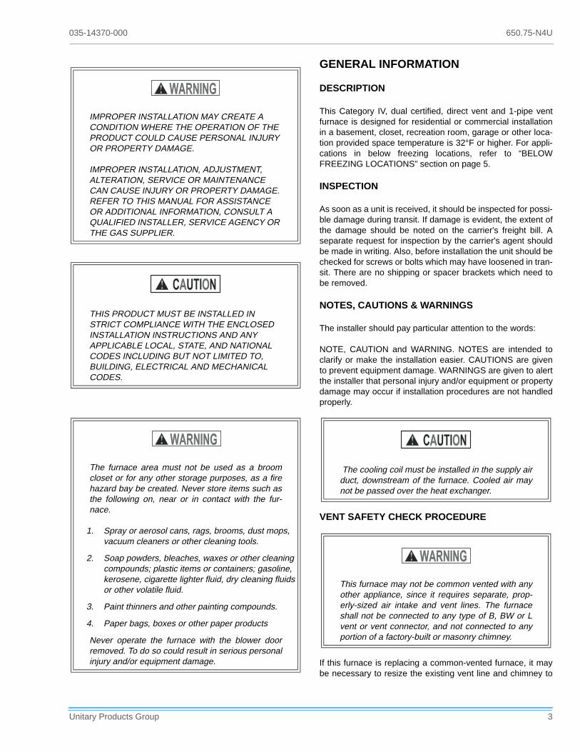
IMPROPER INSTALLATION MAY CREATE A CONDITION WHERE THE OPERATION OF THE PRODUCT COULD CAUSE PERSONAL INJURY OR PROPERTY DAMAGE.
IMPROPER INSTALLATION, ADJUSTMENT, ALTERATION, SERVICE OR MAINTENANCE CAN CAUSE INJURY OR PROPERTY DAMAGE. REFER TO THIS MANUAL FOR ASSISTANCE OR ADDITIONAL INFORMATION, CONSULT A QUALIFIED INSTALLER, SERVICE AGENCY OR THE GAS SUPPLIER.
THIS PRODUCT MUST BE INSTALLED IN STRICT COMPLIANCE WITH THE ENCLOSED INSTALLATION INSTRUCTIONS AND ANY APPLICABLE LOCAL, STATE, AND NATIONAL CODES INCLUDING BUT NOT LIMITED TO, BUILDING, ELECTRICAL AND MECHANICAL CODES.
The furnace area must not be used as a broomcloset or for any other storage purposes, as a firehazard bay be created. Never store items such asthe following on, near or in contact with the fur-nace.
1. Spray or aerosol cans, rags, brooms, dust mops, vacuum cleaners or other cleaning tools.
2. Soap powders, bleaches, waxes or other cleaning compounds; plastic items or containers; gasoline, kerosene, cigarette lighter fluid, dry cleaning fluids or other volatile fluid.
3. Paint thinners and other painting compounds.
4. Paper bags, boxes or other paper products
Never operate the furnace with the blower doorremoved. To do so could result in serious personalinjury and/or equipment damage.
The cooling coil must be installed in the supply airduct, downstream of the furnace. Cooled air maynot be passed over the heat exchanger.
This furnace may not be common vented with anyother appliance, since it requires separate, prop-erly-sized air intake and vent lines. The furnaceshall not be connected to any type of B, BW or Lvent or vent connector, and not connected to anyportion of a factory-built or masonry chimney.

650.75-N4U 035-14370-000
4 Unitary Products Group
prevent oversizing problems for the new combination of units.Refer to the National Gas Code (ANSI Z223.1) or CAN/CGAB149.1 or.2 Installation Code (latest editions).
The following steps shall be followed with each applianceconnected to the venting system placed in operation, whileany other appliances connected to the venting system are notin operation:
1. Seal any unused openings in the venting system.
2. Inspect the venting system for proper size and horizontal pitch, as required in the National Fuel Gas Code, ANSI Z223.1, or the CAN/CGA B149 Installation Codes and these instructions. Determine that there is no blockage or restriction, leakage, corrosion or other deficiencies which could cause an unsafe condition.
3. Insofar as is practical, close all building doors and win-dows and all doors between the space in which the appli-ance(s) is located and other spaces of the building. Turn on clothes dryers. Turn on any exhaust fans, such as range hoods and bathroom exhausts, so they shall oper-ate at maximum speed. Do not operate a summer exhaust fan. Close fireplace dampers.
4. Follow the lighting instructions. Place the appliance being inspected in operation. Adjust thermostat so the appliance shall operate continuously.
5. Test for draft hood equipped appliance spillage at the draft hood relief opening after 5 minutes of main burner operation. Use the flame of a match or candle.
6. After it has been determined that each appliance con-nected to the venting system properly vents when tested as outlined above, return doors, windows, exhaust fans, fireplace dampers and any other gas burning appliance to their previous conditions of use.
7. If improper venting is observed during any of the above tests, the venting system must be corrected.
8. Any corrections to the common venting system must be in accordance with the National Fuel Gas Code Z223.1 or CAN/CGA B149.1 or.2 Installation Code (latest edi-tions). If the common vent system must be resized, it should be resized to approach the minimum size as determined using the appropriate tables in Appendix G of the above codes.
SPECIFIC UNIT INFORMATION
LIMITATIONS & LOCATION
This furnace should be installed in accordance with allnational and local building/safety codes and requirements, orin the absence of local codes, with the National Fuel GasCode ANSI Z223.1 or CAN/CGA B149.1 or.2 InstallationCode (latest editions), local plumbing or waste water codes,and other applicable codes.
Downflow/horizontal models are AGA/CGA listed for down-flow application into a manufactured (mobile) home.
Upflow models or horizontal applications are not approved formobile homes.
A manufactured (mobile) home installation must conform withthe Manufactured Home Construction and Safety Standard,Title 24 CFR, Part 3280, or when this standard is not applica-ble, the Standard for Manufactured Home Installations (Man-ufactured Home Sites, Communities and Set-Ups), ANSIA225.1, and/or CAN/CSA-Z240 MH Series, Mobile Homes.
CLEARANCES FOR ACCESS
Ample clearances should be provided to permit easy accessto the unit. The following minimum clearances are recom-mended:
1. Twenty-four (24) inches between the front of the furnace and an adjacent wall or another appliance, when access is required for servicing and cleaning.
2. Eighteen (18) inches at the side where access is required for passage to the front when servicing or for inspection or replacement of flue/vent connections.
NOTE:In all cases, accessibility clearances shall take prece-dence over clearances for combustible materials whereaccessibility clearances are greater.
Do not install the furnace in an unconditionedspace or garage that could experience ambienttemperatures of 32F (0C) or lower. For applicationin below freezing locations, See “BELOW FREEZ-ING LOCATIONS” on page 5
The furnace is not to be used for temporary heat-ing of buildings or structures under construction.
This unit must be installed in a level (1/4”) positionside-to-side and front-to-back to provide propercondensate drainage.
Do not allow return air temperature to be below55°F for extended periods. To do so may causecondensation to occur in the main fired heatexchanger.

035-14370-000 650.75-N4U
Unitary Products Group 5
The size of the unit should be based on an acceptable heatloss calculation for the structure.
Check the rating plate to make certain the unit is equipped forthe type of gas supplied, and proper electrical characteristicsare available.
For installations above 2,000 feet, reduce input 4% for each1,000 feet above sea level. Refer to Form 650.75-N2.1V forcorrect pressure switch/orifice or other required conversioninformation.
A furnace installed in a residential garage shall be located sothat all burners and burner ignition devices are located notless that 18" above the garage floor, and located or protectedto prevent damage by vehicles.
Allow clearances from combustible materials as listed underClearances to Combustibles, ensuring that service access isallowed for both the burners and blower.
When the furnace is used in conjunction with a cooling coil,the furnace must be installed parallel with or on the upstreamside of the cooling unit to avoid condensation in the primaryheat exchanger.
When a parallel flow arrangement is used, the dampers orother means used to control air flow shall be adequate to pre-
vent chilled air from entering the furnace, and if manuallyoperated, must be equipped with means to prevent operationof either unit unless the damper is in the full heat or cool posi-tion.
The furnace shall be located:
1. Where a minimum amount of air intake/vent piping and elbows will be required.
2. As centralized with the air distribution as possible.
3. In an area where ventilation facilities provide for safe lim-its of ambient temperature under normal operating con-ditions. Ambient temperatures must not fall below 32°F (0°C).
4. Where it will not interfere with proper air circulation in the confined space.
5. Where the outdoor combustion air/vent terminal will not be blocked or restricted.
6. Where it will not interfere with the cleaning, servicing or removal of other appliances.
CLEARANCES TO COMBUSTIBLES
Minimum clearances from combustible construction areshown in Table 3, “UNIT CLEARANCES TO COMBUSTI-BLES,” on page 8.
BELOW FREEZING LOCATIONS
If this furnace is installed in any area where the ambient tem-perature may drop below 32° F, a UL listed self regulatedheat tape must be installed. It is recommended that self regu-lating heat tape rated at 3 watts per foot be used. This mustbe installed around the condensate drain lines in the uncondi-tioned space. Always install the heat tape per the manufac-turer's instructions. Cover the self-regulating heat tape withfiberglass or other heat resistant, insulating material.
Furnaces shall not be installed directly on carpet-ing, tile or other combustible material other thanwood flooring. An accessory combustible floorbase is available to allow direct installation ofdownflow models on combustible flooring.
Furnace shall be installed so the electrical compo-nents are protected from water.

650.75-N4U 035-14370-000
6 Unitary Products Group
TABLE 1: RATINGS & PHYSICAL / ELECTRICAL DATA - UPFLOW MODELS (P*UR/FG9-UP/G9T-UP)
MODELS P*UR/FG9-UP/G9T—UP CABINET
WIDTHAFUE1
AIR TEMP
RISE °F
CFM @ MEAN AIR
TEMP RISE
MAX. OUTLET
AIR TEMP. °F
BLOWER TOTAL UNIT AMPS
MAX OVER-CURRENT
PROTECT2
MIN WIRE SIZE (AWG) @ 75 FT.
ONE WAY2INPUT
MBH
OUTPUT MBH
NOM. CFM
DIA (IN)WIDTH (IN.)
HP
40 37 800 14-1/2 92.4 35 - 65 685 165 9 6 1/4 9.0 20 14
60 55 1000 17-1/2 92.2 45 - 75 850 175 10 6 1/3 9.0 20 14
80 74 1200 17-1/2 92.0 35 - 65 1160 165 11 8 1/2 9.0 20 14
80 76 1600 21 94.3 30 - 60 1540 160 11 8 3/4 12.0 20 14
100 93 1400 21 92.2 45 - 75 1465 175 10 10 1/2 9.0 20 14
100 94 2000 21 93.0 30 - 60 1955 160 11 10 1 12.0 20 14
120 112 2000 24-1/2 92.0 45 - 75 1730 175 11 10 1 12.0 20 14
140 130 2000 24-1/2 92.0 45 - 75 2005 175 11 10 1 12.0 20 14
1. AFUE numbers are determined in accordance with DOE test procedures2. Wire size and overcurrent protection must comply with the National Electrical Code (NFPA-70-latest edition).
For altitudes above 2,000 ft., reduce capacity 4% for each 1,000 ft. above sea level. Refer to Form 650.74-N1.1V.Wire size based on copper conductors, 60°C, 3% voltage drop.Continuous return air temperature must not be below 55°F.
�� � �
� � � � � �
�
� �
� � � � � � � � � � � � � � � � � �
� � � � � � � � � � �� � � � � � � � � � � � � �� � � � � � � � � � � � �
� � � � � �
� � � � �
�
� � �
� � � � �
� � � � � �� � � � �
� � � � �� � � � �
� � � � � � � � � � �
� � � � � � � � � � �
� � � ! � " # � #
� � � � � � � � �� � � �
� � � ! � � � � �
� � � � �� � � � � � � � � �� � � � � ! � $ � � � � � � !� % % � & ' ( � ) * ) +, - . . + , / * - . ( � � � � ! � � � �
� � � � �
0 � � � �
� � � � �
Models P*XU & G9D—UH
A
60 / 55 / 1200 / “B” 17-1/2 16
80 / 75 / 1200 / “B” 17-1/2 16
80 / 75 / 1600 / “C” 21 19
100 / 95 / 1400 / “C” 21 19
100 / 95 /2000 / “C” 21 19
120 / 112 / 2000 / “D” 24-1/2 23
1. Vent pipe must be increased
� � � � � � � �
1 + . / � � - . . + , / * - .
�
� 2 + . / � ( * 3 + �
� � �
4 � � � �� . / ' 5 +
� - . . + , / * - .
�
�
� � � � � � � � � � �
� � � � � � �
� �
� � �
� � � !4 � � � �
� �
� � � � � �� � � � � � � � � � � � � �
�� � �
� � � � � �
�
� �
� � � � � � � � � � � � � � � � � �
� � � � � � � � � � �� � � � � � � � � � � � � �� � � � � � � � � � � � �
� � � � � �
� � � � �
�
� � �
� � � � �
� � � � � �� � � � �
� � � � �� � � � �
� � � � � � � � � � �
� � � � � � � � � � �
� � � ! � " # � #
� � � � � � � � �� � � �
� � � ! � � � � �
� � � � �� � � � � � � � � �� � � � � ! � $ � � � � � � !� % % � & ' ( � ) * ) +, - . . + , / * - . ( � � � � ! � � � �
� � � � �
0 � � � �
� � � � �
� � � � � � � �
1 + . / � � - . . + , / * - .
�
� 2 + . / � ( * 3 + �
� � �
4 � � � �� . / ' 5 +
� - . . + , / * - .
�
�
� � � � � � � � � � �
� � � � � � �
� �
� � �
� � � !4 � � � �
� �
� � � � � �� � � � � � � � � � � � � �
Models P*UR/FG9-UP/G9T—UP
A B C D E
40 / 37 / 800 / A 14-1/2 12-3/4 10-1/8 2 2
60 / 55 / 1000 / B 17-1/2 16-1/4 13-1/8 2 2
80 / 75 / 1200 / B 17-1/2 16-1/4 13-1/8 2 2
80 / 75 / 1600 / C 21 19-3/4 16-5/8 2 2
100 / 95 / 1400 / C 21 19-3/4 16-5/8 2 2
100 / 95 / 2000 / C 21 19-3/4 16-5/8 2 2
120 / 112 / 2000 / D 24-1/2 23-1/4 20-1/8 3 2 (3)1
1. Vent pipe must be increased to 3” on this model.
140 / 130 / 2000 / D 24-1/2 23-1/4 20-1/8 3 2 (3)1ALL DIMENSIONS ARE IN INCHES, AND ARE APPROXIMATE.
FIGURE 1 : DIMENSIONS - UPFLOW MODELS: P*UR/FG9-UP/G9T-UP
035-14370-000 650.75-N4U
Unitary Products Group 7
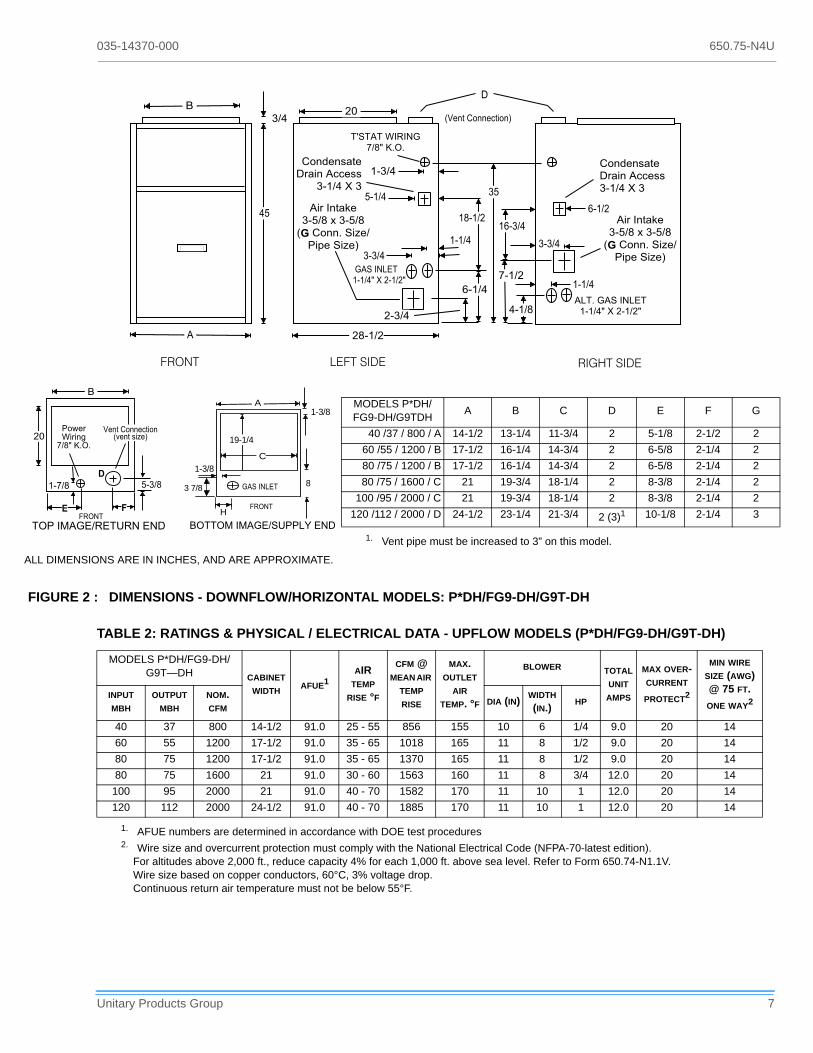
TABLE 2: RATINGS & PHYSICAL / ELECTRICAL DATA - UPFLOW MODELS (P*DH/FG9-DH/G9T-DH)
MODELS P*DH/FG9-DH/G9T—DH CABINET
WIDTHAFUE1
AIR TEMP
RISE °F
CFM @ MEAN AIR
TEMP RISE
MAX. OUTLET
AIR TEMP. °F
BLOWER TOTAL UNIT AMPS
MAX OVER-CURRENT
PROTECT2
MIN WIRE SIZE (AWG) @ 75 FT.
ONE WAY2INPUT
MBH
OUTPUT MBH
NOM. CFM
DIA (IN)WIDTH (IN.)
HP
40 37 800 14-1/2 91.0 25 - 55 856 155 10 6 1/4 9.0 20 14
60 55 1200 17-1/2 91.0 35 - 65 1018 165 11 8 1/2 9.0 20 14
80 75 1200 17-1/2 91.0 35 - 65 1370 165 11 8 1/2 9.0 20 14
80 75 1600 21 91.0 30 - 60 1563 160 11 8 3/4 12.0 20 14
100 95 2000 21 91.0 40 - 70 1582 170 11 10 1 12.0 20 14
120 112 2000 24-1/2 91.0 40 - 70 1885 170 11 10 1 12.0 20 14
1. AFUE numbers are determined in accordance with DOE test procedures2. Wire size and overcurrent protection must comply with the National Electrical Code (NFPA-70-latest edition).
For altitudes above 2,000 ft., reduce capacity 4% for each 1,000 ft. above sea level. Refer to Form 650.74-N1.1V.Wire size based on copper conductors, 60°C, 3% voltage drop.Continuous return air temperature must not be below 55°F.
� � �
� � � � � � � � � � � � � � � � � �
� � � � � � � � �� � � � � ! � $ � � � � � � !
�
� 1 + . / � � - . . + , / * - . �
� � � � �
� � # � � � � � � � � �� � � � � ! � $ � � � � � � !
� � � � � � � � � � �� � � ! � " # � #
� �
� � � � � � �
� � �� � �
� �
� �
� � � � � �
� � � � � �
� � � � � �
� � � � � �
� � � � �
� � � � � �
* 6 � � . / ' 5 +� � � � � � 7 � � � � � � �� � � � - . . # � � * 3 + � �
* ) + � � * 3 + �
� � � � �
� � � � �
* 6 � � . / ' 5 +� � � � � � 7 � � � � � � �� � � � - . . # � � * 3 + � �
* ) + � � * 3 + �
� � � � �
� � � � � �
� - . 8 + . ( ' / +� 6 ' * . � , , + ( (� � � � � � $ � �
� � � � � �
� � � � �
� - . 8 + . ( ' / +� 6 ' * . � , , + ( (
� � � � � � $ � �
� � � � 9 � � � � � � � � � � � � �
1 + . / � � - . . + , / * - .� 2 + . / � ( * 3 + �
�
�
� � �
- : + 6� * 6 * . &
� � � ! � " # � #
4 � � � �� �
� � � � � � � � � �
� � � � � 9 � � 9 � � � � � � ; � � � �
1-3/8
19-1/4
4 � � � �
1-3/8
A
C
8� � � � � � � � �
H
3 7/8
MODELS P*DH/FG9-DH/G9TDH
A B C D E F G
40 /37 / 800 / A 14-1/2 13-1/4 11-3/4 2 5-1/8 2-1/2 2
60 /55 / 1200 / B 17-1/2 16-1/4 14-3/4 2 6-5/8 2-1/4 2
80 /75 / 1200 / B 17-1/2 16-1/4 14-3/4 2 6-5/8 2-1/4 2
80 /75 / 1600 / C 21 19-3/4 18-1/4 2 8-3/8 2-1/4 2
100 /95 / 2000 / C 21 19-3/4 18-1/4 2 8-3/8 2-1/4 2
120 /112 / 2000 / D 24-1/2 23-1/4 21-3/4 2 (3)1
1. Vent pipe must be increased to 3” on this model.
10-1/8 2-1/4 3
ALL DIMENSIONS ARE IN INCHES, AND ARE APPROXIMATE.
FIGURE 2 : DIMENSIONS - DOWNFLOW/HORIZONTAL MODELS: P*DH/FG9-DH/G9T-DH

650.75-N4U 035-14370-000
8 Unitary Products Group
DUCTWORK
The duct system's design and installation must:
1. Handle an air volume appropriate for the served space and within the operating parameters of the furnace spec-ifications.
2. Be installed in accordance with standards of NFPA (National Fire Protection Association) as outlined in NFPA pamphlets 90A and 90B (latest editions) or appli-cable national, provincial, local fire and safety codes.
3. Create a closed duct system. The supply duct system must be connected to the furnace outlet and the return duct system must be connected to the furnace inlet. Both supply and return duct systems must terminate outside the space containing the furnace.
4. Generally complete a path for heated or cooled air to cir-culate through the air conditioning and heating equip-ment and to and from the conditioned space.
When the furnace is used in conjunction with a cooling coil,the furnace must be installed parallel with, or on the upstreamside of the cooling unit to avoid condensation in the primaryheat exchanger.
When a parallel flow arrangement is used, the dampers orother means used to control air flow must be adequate to pre-vent chilled air from entering the furnace, and if manuallyoperated, must be equipped with means to prevent operatingof either unit unless the damper is in the full heat or cool posi-tion.
UPFLOW MODELS
SUPPLY PLENUM CONNECTION
Attach the supply plenum to the fur-nace outlet duct connection flanges.This is typically through the use of Scleat material when a metal plenum isused. The use of an approved flexibleduct connector is recommended on allinstallations. This connection should besealed to prevent air leakage.
If a matching cooling coil is used, itmay be placed directly on the furnaceoutlet and sealed to prevent leakage.Follow the coil instructions for installingthe supply plenum.
On all installations without a coil, a removable access panelis recommended in the outlet duct such that smoke orreflected light would be observable inside the casing to indi-cate the presence of leaks in the heat exchanger. Thisaccess cover shall be attached in such a manner as to pre-vent leaks.
TABLE 3: UNIT CLEARANCES TO COMBUSTIBLES
APPLICATION TOP FRONT REARLEFT SIDE
RIGHT SIDE
FLUEFLOOR/BOTTOM
CLOSET ALCOVE ATTICLINE CON-TACT
UPFLOW MODELS (P*UR / FG9-UP / G9T-UP)
UPFLOW 1 3 0 0 0 0 COMBUSTIBLE YES YES YES NO
DOWNFLOW / HORIZONTAL MODELS (P*DH / FG9-DH / G9T-DH)
DOWNFLOW 1 3 0 0 0 0 1" 1 YES YES YES NO
HORIZONTAL 0 3 0 1 1 0 COMBUSTIBLE2 NO YES YES YES3
1. Special floor base or air conditioning coil required for use on combustible floor.2. Minimum of 8” clearance required to install condensate removal system.3. Line contact only permitted between lines formed by the intersection of the rear panel and side panel (top in horizontal position) of the
furnace jacket and building joists, studs or framing.
If this unit is installed in an unconditioned spaceand an extended power failure occurs, there willbe potential damage to the condensate trap, drainlines and internal unit components. Following apower failure situation, Do Not Operate the UnitUntil Inspection and Repair Are Performed.
The cooling coil must be installed in the supply airduct downstream of the furnace.

035-14370-000 650.75-N4U
Unitary Products Group 9
RETURN DUCT CONNECTION
Return air may enter the furnace through the side(s) or bot-tom depending on the type of application. Return air maynot be connected into the rear panel of the unit. See thespecific type application installation for details. Be sure to seethe Filters section of this instruction.
UPFLOW FILTER INSTALLATION
All applications require the use of a filter. A high velocity filterand retainer are provided for field installation.
Internal Installation
1. Select desired filter position (left/right side, or bottom). Remove the corresponding cabinet cut-outs per instruc-tions provided.
2. Install snap-in retainer clips into the corresponding slots from the outside rear of the cabinet (Refer to Figure 3.) To prevent cabinet air leaks, install snap-in plugs (pro-vided) into the unused slots at the outside rear of the cabinet.
3. Install the wire retainer inside the cabinet. Insert the open ends of the wire retainer into the clip loops at the rear of the blower compartment. The retainer wire should pivot freely like a hinge, on the clips at the rear of the cabinet. (Refer to Figure 4.)
4. Install the filter(s) provided. Cut filter if necessary to match air opening in cabinet. Filter should extend beyond opening edge as much as possible to prevent air from bypassing the filter. DO NOT remove stiffening rods from inside the filter. Shorten the rods, if necessary, to match final filter size.
5. Position the filter between the wire retainer and the cabi-net wall (or floor) so it completely covers the cabinet air opening and secure the filter in place at the front of the cabinet by fastening the closed (looped) end of the retainer wire under the flanged edge of the cabinet. When properly installed the filter should fit flush with all four sides of the cabinet wall.
NOTE: Air velocity through throw-away type filters may notexceed 300 feet per minute. All velocities over this require theuse of high velocity filters.
Side Return - External Filter
Locate and knock out the square corner locators. These indi-cate the size of the cutout to be made in the furnace sidepanel (Refer to Figure 5).
Install the side filter rack following the instructions providedwith that accessory. If a filter(s) is provided at another loca-tion in the return air system, the ductwork may be directlyattached to the furnace side panel.
FIGURE 3 : FURNACE FILTER SLOT LOCATIONS
������������������
��������������
�������������
��������������������
���������������������������
���������������������������������������
FIGURE 4 : SIDE FILTER RETAINER PLACEMENT
FIGURE 5 : SIDE RETURN CUTOUT MARKINGS
��������������������������
�����������
���������
����������������������������� �����������
������������
� � � � � � � �
� � � � �
� � � �
� � � � � � �

650.75-N4U 035-14370-000
10 Unitary Products Group
NOTE:Some accessories such as electronic air cleaners andpleated media may require a larger side opening.
The return duct may be attached to the furnace by S-cleat,bend tabs or other approved methods. Be sure to seal theduct to the furnace to prevent air leakage.
Those applications over 1800 CFM require either return fromtwo sides, one side and the bottom, or bottom only. For bot-tom only application, see data and notes on blower perfor-mance data tables in this manual.
Where the return duct system is not complete, the return con-nection must run full size to a location outside the utility roomor basement. For further details, consult Section 5.3 (Air forCombustion and Ventilation) of the National Fuel Gas Code,ANSI Z223.1, or CAN/CGA B149.1 or.2, Installation Code -latest editions.
Bottom Return
Bottom return applications normally pull return air through abase platform or return air plenum. Be sure the return plat-form structure is suitable to support the weight of the furnace.Be sure to seal the furnace to plenum connection to preventair leakage. (Refer to Figure 3 on page 9) and (Refer toTable 1 on page 6).
The bottom panel is equipped with a perforated opening foreasy removal. Tabs must be cut with sheet metal snips toallow removing knock-out. Scribe marks are included forforming flanges for attachment of the return air ductwork.
NOTE:If an external mounted filter rack is being used, seethe instructions provided with that accessory for proper holecut size.
Upflow attic installations must meet all minimum clearancesto combustibles and have floor support with required serviceaccessibility.
DOWNFLOW/HORIZONTAL MODELS-DOWNFLOW APPLICATION
DOWNFLOW FILTERS
A top return filter rack is supplied withthe furnace. Two 14" x 20" permanentwashable filters are supplied with eachunit.
Downflow furnaces typically areinstalled with the filters located abovethe furnace, extending into the returnair duct.
Any branch duct must attach to the ver-tical ductwork above the filter height(FH) and for proper installation refer toFigure 6.
The filter rack (provided) should be secured to the center ofthe front and rear flanges at the furnace top. Drill a holethrough the front and rear duct flange into the filter rack andsecure it with a sheet metal screw.
Refer to the unit rating plate for furnace model then see thedimensions page of this instruction for return air plenumdimensions. Install the plenum following instructions underDuctwork in this instruction.
All installations must have a filter installed.
FIGURE 6 : DOWNFLOW FILTERS
� � � � � � � � � � � � � � � � � � � � � � � � � �
� � � � � � � � � � � � � � � � � � � � � � �
� � � � � � � � � � � � � � � � � � �
� � � � �
� � � �
� � � � � � � � � � � � � � � � � � � �
� � � � � � � � � � � � � � � � � � � � �
� � � � � � � �
� � � � �
� � � � �
� � � ��
� � � � � � � � � � � � � � � � � � � � �
� � � � � � � � � � � � � � � �
� � � � � � � � �
� � � � � � � � � � � � � � � �
� � � � � � � � � � � � � � � �
� � � � � � � � � � � � � � � � � � � � � � � � � �
� � � � � � � � � � � ! � � � � � � � � � � � � � � � � � � � � � � � � � " � � � � !
� � � � � � � # � � � ! � � � � � � � � � � � � � � � � � � � � � � � � � � � � !
� � � � � � � ! � � � � � � � � � � � � � � � � � � � � � � � � � � � � � � � � � � � � !
� � � � � � � � � � ! � � � � � � � � � � � � � � � � � � � � � � � � � � � $ � " � � !
�
�

035-14370-000 650.75-N4U
Unitary Products Group 11
SUPPLY AIR DUCTS
Installations on combustible material or floors must use acombustible floor base (shown in Figure 7 - 1CB0314, 17, 21& 24) as specified on the rating plate or a matching coolingcoil. Follow the instructions supplied with the combustiblefloor base accessory.
This base can be replaced with a matching cooling coil, prop-erly sealed to prevent leaks. Follow the cooling coil instruc-tions for installing the plenum.
All downflow application supply duct systems must bedesigned and installed in accordance with the standards ofNFPA 90A and 90B, and/or all local codes.
DOWNFLOW / HORIZONTAL MODELS - HORIZONTAL APPLICATION
Downflow furnaces may be installed horizontally with the sup-ply airflow toward the left or right by laying the unit on the leftor right side panel.
After determining the best orientation, lay the unit on top ofthe shipping carton to protect the finish. The appropriate elec-trical knock-outs for power wiring, control wiring and gas pip-ing should be removed at this time.
For horizontal application, return air may enter through theend only. Return air may not be connected into the rearpanel of the unit.
HORIZONTAL FILTERS
All filters and mounting provision must be field supplied. Fil-ters(s) may be located in the duct system external to the fur-nace or in a return filter grille(s).
ATTIC INSTALLATION
FIGURE 7 : COMBUSTIBLE FLOOR BASE ACCESS’Y
��������
�����
��� �� ������
���� �� ������
���������
���������
��������� ���
����� �����
���������� �����
��� ������
Do not install the unit on the rear panel.
FIGURE 8 : TYPICAL ATTIC INSTALLATION
���� ��������������� �������� ������������
�� ������
�������� ���
������ ������� ��
����� ������ ����� �� ���������������� �������� ������������
������ ��
������ ��
���� ���� ���� ������������������ ����� ������ �� �������������� �� ����� ����� ��� ����� �� �������� �����! ����� �� ������

650.75-N4U 035-14370-000
12 Unitary Products Group
This appliance is design certified for line contact for furnacesinstalled horizontally. The intersection of the furnace top andsides form a line. This line may be in contact with combustiblematerial. Refer to “Where it will not interfere with the cleaning,servicing or removal of other appliances." Section on page 5in this manual for additional information.
Secure a platform constructed of plywood or other buildingmaterial to the floor joists. Sheet metal, 12" in front of the fur-nace combustion air openings is recommended. (Refer toFigure 9.)
Note: The unit must be elevated to allow clearnace fo thecondensate trap and drain pipe. .
NOTE:See crawl space installation for suspending the fur-nace in attic installations.
CRAWL SPACE INSTALLATION
The furnace can be hung from floor hoists or installed on suit-able blocks or pad. Blocks or pad installations shall provide
adequate height to ensure the unit will not be subject to waterdamage.
When suspending the furnace from rafters or floor joistsusing rod, pipe or straps, refer to Physical Data and,Table 3,“UNIT CLEARANCES TO COMBUSTIBLES,” on page 8, forfurnace weights to determine suitable means of suspension.
Angle supports should be placed at the supply aire end andnear the blower deck. (Refer to Figure 9.) Do not supportat return air end of unit.
Units may also be suspended by using straps or other mate-rial at the same location. All four suspension points must belevel to ensure quiet furnace operation.
GAS PIPING
The gas supply must be installed in accordance with the cur-rent National Fuel Gas Code, ANSI Z223.1 (in the U.S.) orCAN-B149.1 or.2 (in Canada) installation codes and all appli-cable local and utility requirements. All pipe and fitting mate-rial, pipe size and installation procedures must comply withthe appropriate code. Some utilities may require larger pipesizes than shown in the code. Gas piping may be connectedfrom either side of the furnace. Each side of the unit has twogas pipe entry knockouts.
For downflow/horizontal models, plan your combustion airpiping before determining the correct gas pipe entry. Use 90degree service elbow(s), or short nipples and conventional 90degree elbow(s) to enter through the cabinet access holes..
If this furnace is installed over a finished space, acondensate safety pan must be installed.
When a furnace is installed in an attic or otherinsulated space, keep all insulating materials atleast 12" away from furnace and burner combus-tion air openings.
FIGURE 9 : TYPICAL FURNACE INSTALLATION USING SUSPENSION MATERIALS
����������
���� ���������
"� ��� ���������� # �����
�� �$ ���������� # �����
�� �$ ���������� # �����
In any application where temperatures belowfreezing are possible, See “BELOW FREEZINGLOCATIONS” on page 5
An overpressure protection device, such as apressure regulator, which conforms to the NationalFuel Gas Code, ANSI Z223.1 (U.S.) or CAN-B149.1 or.2 (Canada) and acts to limit the down-stream pressure to a value that does not exceed0.5 PSI (14" w.c.), must be installed in the gas pip-ing system upstream of the furnace. Failure to doso may result in a fire or explosion or cause dam-age to the furnace or some of its components.

035-14370-000 650.75-N4U
Unitary Products Group 13
NOTE: An accessible manual shutoff valve must be installedupstream of the furnace gas controls and within 6 feet of thefurnace.
The installation of a ground joint union and drip leg arerequired. (Refer to Figure 10.) Maximum and minimum sup-ply gas pressures are shown below.
NOTE: A 1/8” NPT plug is included in the inlet side of the gasvalve for measuring incoming gas pressure.
The furnace must be isolated from the gas supply piping sys-tem by closing its individual external manual shutoff valveduring any pressure testing of the gas supply piping systemat pressures equal to or less than 1/2 psig (3.48 kPa).
The furnace and its individual shutoff valve must be discon-nected from the gas supply piping system during any pres-sure testing of that system at test pressures in excess of 1/2psig (3.48 kPa).
ELECTRICAL POWER CONNECTION
Field wiring to the unit must conform to and be grounded inaccordance with the provisions of the National ElectricalCode ANSI/NFPA No. 70-latest edition, Canadian ElectricCode C22.1 Part 1 - (latest edition) and/or local codes. Elec-tric wires which are field installed shall conform with the tem-perature limitation for 63°F/35°C rise wire when installed inaccordance with instructions. Specific electrical data is givenfor the furnace on its rating plate and in Refer to Table 1 onpage 6.
Provide a power supply separate from all other circuits. Installovercurrent protection and disconnect switch per local/national electrical codes. The switch should be close to theunit for convenience in servicing. With the disconnect switchin the OFF position, check all wiring against the unit wiringlabel. Also, see the wiring diagram in this instruction.
NOTE:The furnace’s control system depends on correctpolarity of the power supply and a proper ground connection.“FURNACE CONTROL DIAGNOSTICS" Section on page 37for symptoms of reversed power supply polarity.
Connect the power supply as shown on the unit wiring labelon the inside of the blower compartment door and Figures 11& 12. The black furnace lead must be connected to the L1(hot) wire from the power supply. The white furnace leadmust be connected to neutral. Also, the green equipmentground wire must be connected to the power supply ground.
Remove the screws retaining the wiring box cover. Route thepower wiring through the unit top panel with a conduit con-
INLET GAS PRESSURE RANGE
Natural Gas Propane (LP)
Minimum 4.5 In. W.C. 11 In. W.C.
Maximum 13.8 In. W.C. 13.8 In. W.C.
FIGURE 10 : GAS PIPING
Never apply a pipe wrench to the body of the com-bination automatic gas valve. A wrench must beplaced on the projection or wrench boss of thevalve when installing piping to it.
� � � � � � � �
� � � � � � � �
� � � � � � � % � � � � � � � �� � � � � � � � � � � � � �
� � � � � � � � � � � � � � � �
� � � � � � � � � �
� � & � � � � � � � � � � � � � � � � � � � � � � � �
� � � � � � � � � �
� � � � � � � �
Compounds used on threaded joints of gas pipingmust be resistant to the action of liquefied petro-leum gases. After connections are made, leak-testall pipe connections.
After all gas piping connections are completed,leak test all joints, fittings and furnace connectionswith rich soap and water solution, commerciallyavailable bubble type leak detection fluid, or otherapproved means.
Do not use an open flame or other source of igni-tion for leak testing.
Use copper conductors only.
650.75-N4U 035-14370-000
14 Unitary Products Group
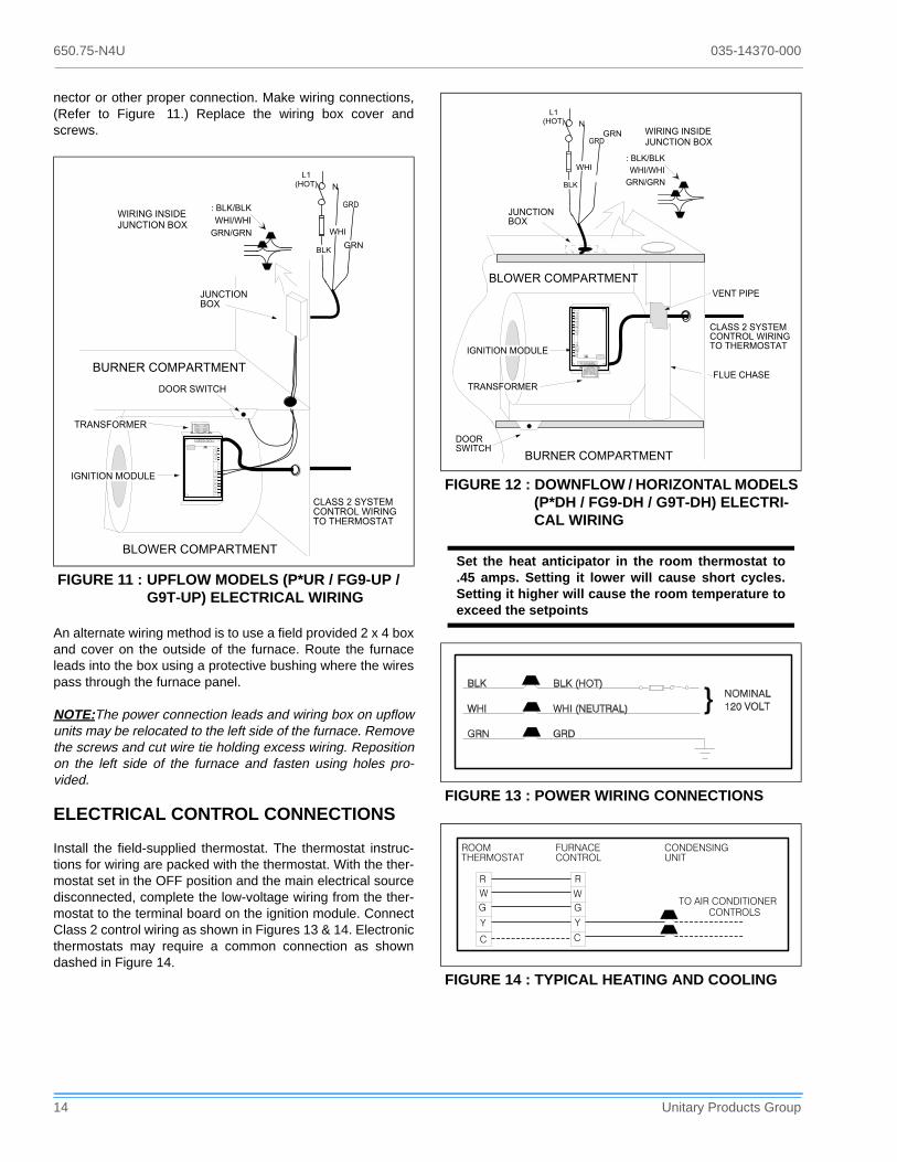
nector or other proper connection. Make wiring connections,(Refer to Figure 11.) Replace the wiring box cover andscrews.
An alternate wiring method is to use a field provided 2 x 4 boxand cover on the outside of the furnace. Route the furnaceleads into the box using a protective bushing where the wirespass through the furnace panel.
NOTE:The power connection leads and wiring box on upflowunits may be relocated to the left side of the furnace. Removethe screws and cut wire tie holding excess wiring. Repositionon the left side of the furnace and fasten using holes pro-vided.
ELECTRICAL CONTROL CONNECTIONS
Install the field-supplied thermostat. The thermostat instruc-tions for wiring are packed with the thermostat. With the ther-mostat set in the OFF position and the main electrical sourcedisconnected, complete the low-voltage wiring from the ther-mostat to the terminal board on the ignition module. ConnectClass 2 control wiring as shown in Figures 13 & 14. Electronicthermostats may require a common connection as showndashed in Figure 14.
FIGURE 11 : UPFLOW MODELS (P*UR / FG9-UP / G9T-UP) ELECTRICAL WIRING
��� � ������������ �������� ���������
������� �
���
������
���
������ ������ ������ ��$
% ���&���
���&���
���&���
������ ���������
������ ���������
���� �����
�������� ������
����������
��������$
�
�
� �
���
���
���
���
$���
����
���
�
$���
�
����
��
���
�
FIGURE 12 : DOWNFLOW / HORIZONTAL MODELS (P*DH / FG9-DH / G9T-DH) ELECTRI-CAL WIRING
Set the heat anticipator in the room thermostat to.45 amps. Setting it lower will cause short cycles.Setting it higher will cause the room temperature toexceed the setpoints
FIGURE 13 : POWER WIRING CONNECTIONS
FIGURE 14 : TYPICAL HEATING AND COOLING
��� � ������������ �������� ���������
��� ������ ������ ������ ��$
% ���&���
���&���
���&���
������ ���������
���� �����
�������� ������
���� ���
���� ����
������ ���������
��������$
������� �
���
���
���
�
�
��
���
���
���
���
$���
����
���
�
$���
�
����
��
���
�
����������
��������������
�����������
�������������
������������������������ �
�
��
�
�
���
�
�

035-14370-000 650.75-N4U
Unitary Products Group 15
NOTE. Some electronic thermostats do not have adjustableheat anticipators. They may have other type cycle rateadjustments. Follow the thermostat manufacturer's instruc-tions.
The 24-volt, 40 VA transformer is sized for the furnace com-ponents only, and should not be connected to power auxiliarydevices such as humidifiers, air cleaners, etc. The trans-former may provide power for an air conditioning unit contac-tor.
COMBUSTION AIR AND VENT SYSTEM
1. Two-pipe with a sealed combustion intake/vent system using outdoor combustion air.
2. Single pipe vent system using combustion air from the area surrounding the furnace.
3. Two-pipe intake/vent system using combustion air from a ventilated attic space and a vent pipe to the outside.
Be sure to follow the appropriate venting section details, related information and limitations for your type of installation.
METHOD ONE: TWO PIPE SEALED COMBUSTION AIR & VENT SYSTEM
COMBUSTION AIR INTAKE/VENT CONNECTIONS
This type installation requires outdoor combustion air. Twoseparate, properly-sized pipes must be used. One bringingair from the outdoors to the furnace combustion air intake col-lar on the burner box, and a second pipe from the furnace
vent connection (top right of unit) back to the outdoors. Referto Figure 15 and Figure 16.
The intake/vent should be located either through the wall(horizontal or side vent) or through the roof (vertical vent).Care should be taken to locate side vented systems wheretrees or shrubs will not block or restrict supply air from enter-ing or combustion products from leaving the terminal.
Also, the terminal assembly should be located as far as pos-sible from a swimming pool or a location where swimmingpool chemicals might be stored. Be sure the terminal assem-bly follows the outdoor clearances listed in Table 3 for U.S.installations: In Canada, refer to CAN/CGA-B149.1 or.2
This furnace is certified to be installed with one ofthree possible intake/vent configurations.
Furnace Intake / Vent Connection Size (All Models)
40 - 100 MBH 120 - 140 MBH
Intake 2” 3"
Vent 2” 2"1
1. Vent must be increased to 3" on this model.Note 1: Any vent pipe size change must be made out-
side furnace casing in a vertical pipe section to allow proper drainage of condensate.
Note 2: An offset using two 45 degree elbows will be required for plenum clearance when the vent is increased to 3”.
FIGURE 15 : UPFLOW AIR INTAKE/VENT LOCATIONS (MODELS P*UR / FG9-UP /G9T-UP)
FIGURE 16 : DOWNFLOW / HORIZONTAL AIR INTAKE/VENT LOCATIONS (MODELS P*DH / FG9-DH /G9T-DH)
���
���
��� �
� � � � � � � � � � � � � �
� � � � � � � � � � � � � � � � � �
� � � � � � � � � � � � �
� � � � � � � � � � � � � �
� � � � � � � � � � � � � � �
� � � � � � � � � � � � �
� � � � � � � � � �
� � � � �
� � � �
� �
� �
� �
� � �
� � � �
�
� � �
� � �
� � �
� � � �
�
� � �
� � � � � � � � � � � �
� � � � � � � � � � � � �
� � � � � � � � � � � � � � �
� � � � � � � � � � � � �
� � � � � � � � � � � � � �
� � �
� � � � � �
� � � � � � � �
� � � � � � � � � � �
� � � � � � � � � �

650.75-N4U 035-14370-000
16 Unitary Products Group
Installation Code (latest edition-Venting Systems and AirSupply).
COMBUSTION AIR/VENT PIPE SIZING
To select the proper size piping for combustion air intake andventing, refer to Table 4 or Table 5. The size will be deter-mined by a combination of furnace model, total length of run,and the number of elbows required. The following rules mustalso be observed.Long radius elbows are required for allunits.
1. Long radius elbows are required for all units.
2. Elbows are assumed to be 90 degrees. Two 45 degree elbows count as one 90 degree elbow.
3. Elbow count refers to combustion air piping and vent pip-ing separately. For example, if the table allows for 5 elbows, this will allow a maximum of 5 elbows in the combustion air piping and a maximum of 5 elbows in the vent piping.
4. Three vent terminal elbows (two for vent pipe and one for air intake pipe) are already accounted for and should not be counted in the allowable total indicated in the table (see vent termination section). These parts are shown shaded.
For downflow/horizontal models only two additional elbows are also accounted for and also should not be counted. These parts are shown shaded.
5. Combustion air and vent piping must be of the same diameter.
6. All combustion air/vent pipe and fittings must conform to American National Standards Institute (ANSI) standards and American Society for Testing and Materials (ASTM) standards D1785 (Schedule 40 PVC), D2665 (PVC-DWV), F891 (PVC-DWV Cellular Core). D2241 (SDR-21 and SDR-26 PVC), D2261 (ABS-DWV), or F628 (Sched-ule 40 ABS. Pipe cement and primer must conform to ASTM Standards D2564 (PVC) or D2235 (ABS).
7. The use of flexible connectors or no hub connectors in the vent system is not allowed. This type connection is allowed in the combustion air pipe near the furnace for air conditioning coil accessibility.
VENT TERMINATION (2-PIPE)
Side wall horizontal vent terminals and roof mounted verticalterminals may be field fabricated. Standard PVC/SRD fittingsmay be used. Terminal configuration must comply as detailedin this section.
TABLE 4: INTAKE/VENT PIPING - 2 PIPE SYSTEM
Models P*UR/FG9-UP/G9T-UP
Pipe Size
Max. Elbows vs. One Way Vent
Length (Ft.)1
5 - 40 45 50 75
40 / 37 / 800 / A
2” 6 5 4 N/A
60 / 55 / 1000 / B
80 / 75 / 1200 / C
80 / 75 / 1600 / C
100 / 95 / 1400 / C
100 / 95 / 2000 / C
40 / 37 / 800 / A
3” 8 7 6 5
60 / 55 / 1000 / B
80 / 75 / 1200 / C
80 / 75 / 1600 / C
100 / 95 / 1400 / C
100 / 95 / 2000 / C
120 / 112 / 2000 / D 3" Only 6 5 4 N/A
140 / 130 / 2000 / D
1. Elbow count does not include the elbows required for the termination. See Step 4 under Combustion Air/Vent Pipe Sizing
TABLE 5: INTAKE/VENT PIPING 2-PIPE SYSTEM
Models P*DH/FG9-DH/G9T-DH
Pipe Size
Max. Elbows vs. One Way
Vent Length (Ft.)1
5-30 35 40 60
40 /37 / 800 / A
2” 6 5 4 N/A
60 /55 / 1200 / B
80 /75 / 1200 / B
80 /75 / 1600 / C
100 /95 / 2000 / C
40 /37 / 800 / A
3” 8 7 6 5
60 /55 / 1200 / B
80 /75 / 1200 / B
80 /75 / 1600 / C
100 /95 / 2000 / C
120 /112 / 2000 / D 3" Only 6 5 4 N/A
1. Elbow count does not include (2) 90 ° elbows required to pipe intake into burner box or those required for the termination. See Step 4 under Combustion Air/Vent Pipe Sizing

035-14370-000 650.75-N4U
Unitary Products Group 17
NOTE:Combustion air and vent pipes must terminatetogether in the same atmospheric zone, either through a roofor sidewall.
When selecting the location for combustion air/vent termina-tion the following should be considered:
1. Comply with all clearance requirements as listed below.
2. Termination should be positioned where vent vapors will not damage plants or shrubs or air conditioning equip-ment.
3. Termination should be located where it will not be affected by wind gusts, light snow, airborne leaves or allow recirculation of flue gases.
4. Termination should be located where it will not be dam-aged or exposed to flying stones, balls, etc.
5. Termination should be positioned where vent vapors are not objectionable.
VENT CLEARANCES (2-PIPE) U.S. ONLY
Dryer Vent . . . . . . . . . . . . . . . . . . . . . . . . . . . . . . . . . . . 3 ft.
Plumbing Vent Stack. . . . . . . . . . . . . . . . . . . . . . . . . . . 3 ft.
Gas Appliance Vent Terminal . . . . . . . . . . . . . . . . . . . 3 ft.*
From any mechanical fresh air intake . . . . . . . . . . . . . . 1 ft.
From any door, window or non-mechanical fresh air orcombustion air intake . . . . . . . . . . . . . . . . . . . . . . . . . . 1 ft.
Above grade and anticipated snow depth. . . . . . . . . . . 1 ft.
Above grade when adjacent to public walkway. . . . . . . 7 ft.
From electric, gas meters, regulators and relief equipment -min. horizontal distance . . . . . . . . . . . . . . . . . . . . . . . . 4 ft.
* Does not apply to multiple installations of this furnace model. Refer to “VENTING MULTIPLE UNITS" Section on page 17 .
NOTE:Consideration must be given for degradation of build-ing materials by flue gases.
NOTE:Shaded components of the combustion air/vent sys-tem shown in the following figures are considered to be partof the vent terminal. These components should not becounted when determining piping limitations. Refer to Figure
17 to Figure 22. Sidewall termination may require sealing orshielding of building surfaces with a corrosive resistancematerial to protect against combustion product corrosion.
VENTING MULTIPLE UNITS
Each unit must have its own intake/vent piping and termina-tion. Do not use common pipes for combustion air or venting.The vent terminals must be located as shown in Figure 21and FIGURE 22.
NOTE:Accessory concentric intake/vent terminations,models 1CT0302 and 1CT0303 are available andapproved for use with these furnaces. Refer to Form650.75-N2.4V for installation details.
In Canada, refer to CAN/CGA-B149.1 or.2 InstallationCode (latest edition - Venting Systems and Air Supply)
FIGURE 17 : HORIZONTAL TERMINATION CON-FIGURATION WITH 12” MINIMUM CLEARANCE
FIGURE 18 : HORIZONTAL TERMINATION RAISED CONFIGURATION FOR ADDITIONAL CLEARANCE
����
�������
��� ���������
����������������������������������� ���������������������������
���������������������������������������������������������������������������������
��������� �
���
����
�������
��� ���������������������������������
����������������������������������� ���������������������������
���������������������������������������������������������������������������������
��������� �
���

650.75-N4U 035-14370-000
18 Unitary Products Group
PIPING ASSEMBLY
The final assembly procedure for the vent/combustion air pip-ing is as follows:
1. Cut piping to the proper length, beginning at the furnace.
2. Deburr the piping inside and outside.
3. Chamfer the outer edges of the piping.
4. Dry-fit the entire vent/combustion air piping assembly.
5. Disassemble the piping and apply cement primer and cement per the cement manufacturer's instructions. Primer and cement must conform to ASTM D2564 for PVC, or ASTM D2235 for ABS piping.
6. All joints must be made to provide a permanent, air-tight, water-tight seal.
7. Support the combustion air and vent piping such that it is angled 1/4” per linear foot so that condensate will flow back toward the furnace. Piping should be supported with pipe hangers to prevent sagging. Maximum spacing between hangers is five (5) feet, except SDR-PVC pip-ing, where maximum spacing is three (3) feet.
8. Seal around the openings where the combustion air and vent piping pass through the roof of side wall.
FIGURE 19 : HORIZONTAL TERMINATION CON-FIGURATION WITH HORIZONTAL EXTENSION
FIGURE 20 : VERTICAL TERMINATION
FIGURE 21 : DOUBLE SIDEWALL TERMINATION
����
�������
��� ���������
����������������������������������� ���������������������������
���������������������������������������������������������������������������������
��������� �
���
������ �� �
������������������ ������������������������������������������!�� �� ������"������������
��� ���������
����
��������������������������������� �����������������
����
��� ���������
��
FIGURE 22 : DOUBLE ROOFTOP TERMINATION
Solvent cements are flammable and must be usedin well-ventilated areas only. Keep them away fromheat, sparks and open flames (including pilots). Donot breathe vapors and avoid contact with skin andeyes.
#�
035-14370-000 650.75-N4U
Unitary Products Group 19
Note:Vent pipe must be sloped 1/4” per foot to allow conden-sate to flow back to the furnace.
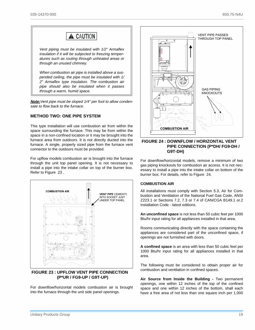
METHOD TWO: ONE PIPE SYSTEM
This type installation will use combustion air from within thespace surrounding the furnace. This may be from within thespace in a non-confined location or it may be brought into thefurnace area from outdoors. It is not directly ducted into thefurnace. A single, properly sized pipe from the furnace ventconnector to the outdoors must be provided.
For upflow models combustion air is brought into the furnacethrough the unit top panel opening. It is not necessary toinstall a pipe into the intake collar on top of the burner box.Refer to Figure 23 .
For downflow/horizontal models combustion air is broughtinto the furnace through the unit side panel openings.
For downflow/horizontal models, remove a minimum of twogas piping knockouts for combustion air access. It is not nec-essary to install a pipe into the intake collar on bottom of theburner box. For details, refer to Figure 24.
COMBUSTION AIR
All installations must comply with Section 5.3, Air for Com-bustion and Ventilation of the National Fuel Gas Code, ANSIZ223.1 or Sections 7.2, 7.3 or 7.4 of CAN/CGA B149.1 or.2Installation Code - latest editions.
An unconfined space is not less than 50 cubic feet per 1000Btu/hr input rating for all appliances installed in that area.
Rooms communicating directly with the space containing theappliances are considered part of the unconfined space, ifopenings are not furnished with doors.
A confined space is an area with less than 50 cubic feet per1000 Btu/hr input rating for all appliances installed in thatarea.
The following must be considered to obtain proper air forcombustion and ventilation in confined spaces.
Air Source from Inside the Building - Two permanentopenings, one within 12 inches of the top of the confinedspace and one within 12 inches of the bottom, shall eachhave a free area of not less than one square inch per 1,000
Vent piping must be insulated with 1/2” Armaflexinsulation if it will be subjected to freezing temper-atures such as routing through unheated areas orthrough an unused chimney.
When combustion air pipe is installed above a sus-pended ceiling, the pipe must be insulated with 1/2” Armaflex type insulation. The combustion airpipe should also be insulated when it passesthrough a warm, humid space.
FIGURE 23 : UPFLOW VENT PIPE CONNECTION (P*UR / FG9-UP / G9T-UP)
��
�$�
��� �
�
������������ �������������������%���& �� ��������������
FIGURE 24 : DOWNFLOW / HORIZONTAL VENT PIPE CONNECTION (P*DH/ FG9-DH / G9T-DH)
� � � � �
� � � �
� �
� �
� �
� � �
� � � �
�
� � �
� � �
� � �
� � � �
�
� � �
� � � � � � � � � � � � �
� � � � � � � � � � � � � �
� � � � � � � � � � � �
� � � � � � � � �
� � � � � � �
650.75-N4U 035-14370-000
20 Unitary Products Group
Btuh of total input rating of all appliances located in thespace. The openings shall communicate freely with interiorareas having adequate infiltration from the outside.
NOTE: At least 100 square inches free area shall be used foreach opening.
Air Source from Outdoors -
1. Two permanent openings, one within 12 inches of the top of the confined space and one within 12 inches of the bottom, shall communicate directly, or by means of ducts, with the outdoors or to such crawl or attic spaces that freely communicate with the outdoors.
a. Vertical Ducts - Each opening must have a freearea of not less than one square inch per 4,000 Btuhof total input of all appliances located in the space.
EXAMPLE:
b. Horizontal Ducts - Each opening must have a freearea of not less than one square inch per 2,000 Btuhof total input of all appliances located in the space.
NOTE: Ducts must have the same cross-sectional area asthe free area in the opening to which they are connected. Theminimum dimension of rectangular ducts shall be threeinches.
2. One permanent opening, commencing within 12 inches of the top of the enclosure shall be permitted where the equipment has clearances of at least 1 inch from the sides and back and 6 inches from the front of the appli-ance. The opening shall communicate through a vertical or horizontal duct to the outdoors, or spaces (crawl or attic) that freely communicate with the outdoors and shall have a minimum free area of:
a. 1 sq. in. per 3000 Btu per hr of the total input ratingof all equipment located in the enclosure.
b. Not less than the sum of the areas of all vent con-nectors in the confined space.
3. Louvers, Grilles and Screens
a. In calculating free area, consideration must be givento the blocking effects of louvers, grilles andscreens.
b. If the free area of a specific louver or grille is notknown, refer to Table 6, to estimate free area.
NOTE: If mechanically operated louvers are used, a meansto prevent main burner ignition and operation must be pro-vided should louvers close during startup or operation.
Special Combustion and Ventilation Considerations
Operation of a mechanical exhaust, such as an exhaust fan,kitchen ventilation system, clothes dryer or fireplace may cre-ate conditions requiring special attention to avoid unsatisfac-tory operation of gas appliances.
Specially Engineered Installations
The above requirements shall be permitted to be waivedwhere special engineering, approved by the authority havingjurisdiction, provides an adequate supply of air for combus-tion, ventilation and dilution of flue gases.
Combustion Air Quality
The recommended source of combustion air is to use the out-door air supply. Excessive exposure to contaminated com-bustion air will result in safety and performance relatedproblems. However, the use of indoor air in most applicationsis acceptable, except as follows:
1. If the furnace is installed in a confined space it is recom-mended that the necessary combustion air come from the outdoors by way of attic, crawl space, air duct or direct opening.
2. If indoor combustion air is used, there must be no expo-sure to the installations or substances listed in 3 below.
3. The following types of installations may require OUT-DOOR AIR for combustion, due to chemical exposure.
a. Commercial buildings
b. Buildings with indoor pools
c. Furnaces installed in laundry rooms
d. Furnaces installed in hobby or craft rooms
e. Furnaces installed near chemical storage areas
Exposure to the following substances in the combustion airsupply may also require OUTDOOR AIR for combustion.
f. Permanent wave solutions
g. Chlorinated waxes and cleaners
h. Chlorine based swimming pool chemicals
i. Water softening chemicals
Total Input of All Appliances= Square Inches Free Area
4000
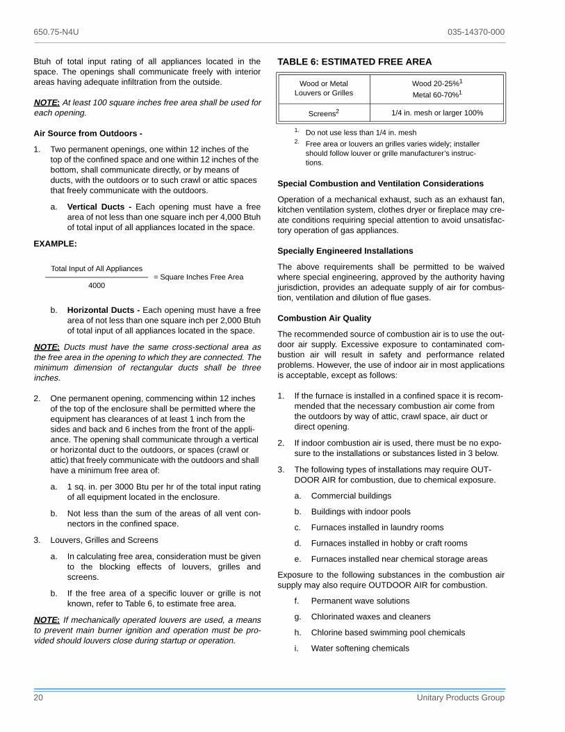
TABLE 6: ESTIMATED FREE AREA
Wood or MetalLouvers or Grilles
Wood 20-25%1
Metal 60-70%1
Screens2 1/4 in. mesh or larger 100%
1. Do not use less than 1/4 in. mesh2. Free area or louvers an grilles varies widely; installer
should follow louver or grille manufacturer’s instruc-tions.

035-14370-000 650.75-N4U
Unitary Products Group 21
j. De-icing salts or chemicals
k. Carbon tetrachloride
l. Halogen type refrigerants
m. Cleaning solvents (such as perchloroethylene)
n. Printing inks, paint removers, varnishes, etc.
o. Hydrochloric acids
p. Cements and glues
q. Antistatic fabric softeners for clothes dryers
r. Masonry acid washing chemicals
VENT PIPE SIZING (1-PIPE SYSTEM)
Refer to Table 7 to select the proper size piping for venting.The size will be determined by a combination of furnacemodel, total length of run, and the number of elbows required.The following rules must also be observed.
NOTE:Furnace vent pipe connections are sized for 2-in. pipe.Any pipe size change must be made outside the furnace cas-ing in a vertical pipe section to allow proper drainage of ventconnections.
NOTE:An offset using two 45 degree elbows may be requiredfor plenum clearance when the vent is increased to 3".
1. Long radius elbows are required for all units.
2. Elbows are assumed to be 90 degrees. Two 45 degree elbows count as one 90 degree elbow.
3. One Vent terminal elbow is already accounted for and should not be counted in the allowable total indicated in the table. See “VENT TERMINAL LOCATION CLEARANCES" Section on page 21 . This part is shown shaded.
4. All vent pipe and fittings must conform to American National Standards Institute (ANSI) standards and Amer-ican Society for Testing and Materials (ASTM) standards D1785 (Schedule 40 PVC), D2665 (PVC-DWV), F891 (PVC-DWV Cellular Core), D2241 (SDR-21 and SDR-26 PVC), D2261 (ABS-DWV), or F628 (Schedule 40 ABS. Pipe cement and primer must conform to ASTM Stan-dards D2564 (PVC) or D2235 (ABS).
5. The use of flexible connectors or no hub connectors in the vent system is not allowed.:
VENT TERMINATION (1-PIPE SYSTEM)
Side wall horizontal vent terminals and roof mounted verticalterminals may be field fabricated. Standard PVC/SRD fittingsmay be used. Terminal configuration must comply as detailedin this section.
When selecting the locations for vent termination, the follow-ing should be considered:
1. Comply with all clearance requirements. (Refer to Figure 25 on page 22)
2. Termination should be positioned where vent vapors will not damage plants or shrubs or air conditioning equip-ment.
3. Termination should be located where it will not be affected by wind gusts, light snow, airborne leaves or allow recirculation of flue gases.
4. Termination should be located where it will not be dam-aged or exposed to flying stones, balls, etc.
5. Termination should be positioned where vent vapors are not objectionable.
VENT TERMINAL LOCATION CLEARANCES
The vent must be installed with the following minimum clear-ances(Refer to Figure 25 on page 22), and complying withlocal codes or utility requirements or other authority havingjurisdiction.
1. 1 foot above grade and above normal snow levels.
2. Not above any walkway.
3. 4 feet below, 4 feet horizontally from, or 1 foot above any door/window or gravity air inlet to the building, or from gas or electric meters.
TABLE 7: VENT PIPING / 1-PIPE SYSTEM (ALL MODELS)
Model Pipe Size
Max. Elbows vs. One Way Vent Length (Ft.)
5-40 45 50 75
All Models Except:120 / 112 / 2000 / D140 / 130 / 2000 / D
2” 6 5 4 N/A
All Models Except:120 / 112 / 2000 / D140 / 130 / 2000 / D
3” 8 7 6 5
120 / 112 / 2000 / D140 / 130 / 2000 / D
3” Only 6 5 4 N/A
In Canada, refer to CAN/CGA-B149.1 or.2 InstallationCode (latest edition - Venting Systems and Air Supply)

650.75-N4U 035-14370-000
22 Unitary Products Group
4. 6 feet from any inside corner formed by two exterior walls. 10 feet is recommended where possible.
5. At least 4 feet horizontally from any soffit or undereave vent.
6. 10 feet from any forced air inlet to the building. Any fresh air or make up inlet as for a dryer or furnace area is con-sidered to be a forced air inlet.
7. Avoid areas where condensate drippage may cause problems such as above planters, patios, or adjacent to windows where steam may cause fogging.
NOTE:Consideration must be given for degradation of build-ing materials by flue gases.
NOTE:Shaded components of the vent system shown in Fig-ure 25 through Figure 28 are considered to be termination.These components should not be counted when determiningpipe diameter. Sidewall termination may require sealing orshielding of building surfaces with a corrosive resistant mate-rial due to vent system corrosive combustion products.
FIGURE 25 : VENT TERMINAL CLEARANCES (1-PIPE SYSTEM) - U.S. ONLY
INSIDECORNER
SOFFITVENTS
ELECTRICMETER
4' 4'
4'
4'
6'10' RECOMMENDED
4'
1' PLUSSNOW CLEARANCE
4'
FRESH AIRINTAKE
10'3'
FURNACE VENT
FIGURE 26 : HORIZONTAL TERMINATION CON-FIGURATION WITH 12” MINIMUM CLEARANCE
FIGURE 27 : HORIZONTAL TERMINATION RAISED CONFIGURATION FOR ADDITIONAL CLEARANCE
FIGURE 28 : ROOFTOP TERMINATION
���������
�������� ����������������������������������������������������������������������������
��
����
�������� ����������������������������������������������������������������������������
���
�������
�������� ��������������������������������������������������������������������������
����
035-14370-000 650.75-N4U
Unitary Products Group 23
PIPING ASSEMBLY
The final assembly procedure for the vent piping is as follows:
1. Cut piping to the proper length, beginning at the furnace.
2. Deburr the piping inside and outside.
3. Chamfer the outer edges of the piping.
4. Dry-fit the entire vent piping system.
5. Disassemble the piping and apply cement primer and cement per the cement manufacturer's instructions. Primer and cement must conform to ASTM D2564 for PVC, or ASTM D2235 for ABS piping.
6. All joints must be made to provide a permanent, air tight. water tight seal.
7. Support the vent piping such that it is angled 1/4” per lin-ear foot so that condensate will flow back towards the furnace. Piping should be supported with pipe hangers to prevent sagging. Maximum spacing between hangers is 5 feet, except SDR-PVC piping, where maximum spac-ing is 3 feet.
8. Seal around the openings where the vent piping passes through the roof or side wall.
NOTE:Vent pipe must be sloped 1/4” per foot to allow con-densate to flow back to the furnace.
METHOD THREE: TWO PIPE SYSTEM USING COM-BUSTION AIR FROM A VENTILATED ATTIC SPACE
This type installation requires two properly sized pipes. Onebrings combustion air from a properly ventilated attic spaceand a second pipe from the furnace vent connection (top rightof unit) exits to the outdoors.
COMBUSTION AIR INTAKE
Refer to Table 4 on page 16, for intake pipe sizing, allowablelength and elbow usage. Follow all notes, procedures andrequired materials in the Two-Pipe Sealed Combustion sec-tion (Method 1) when installing the combustion air pipe withinthe unit and into the ventilated attic space.
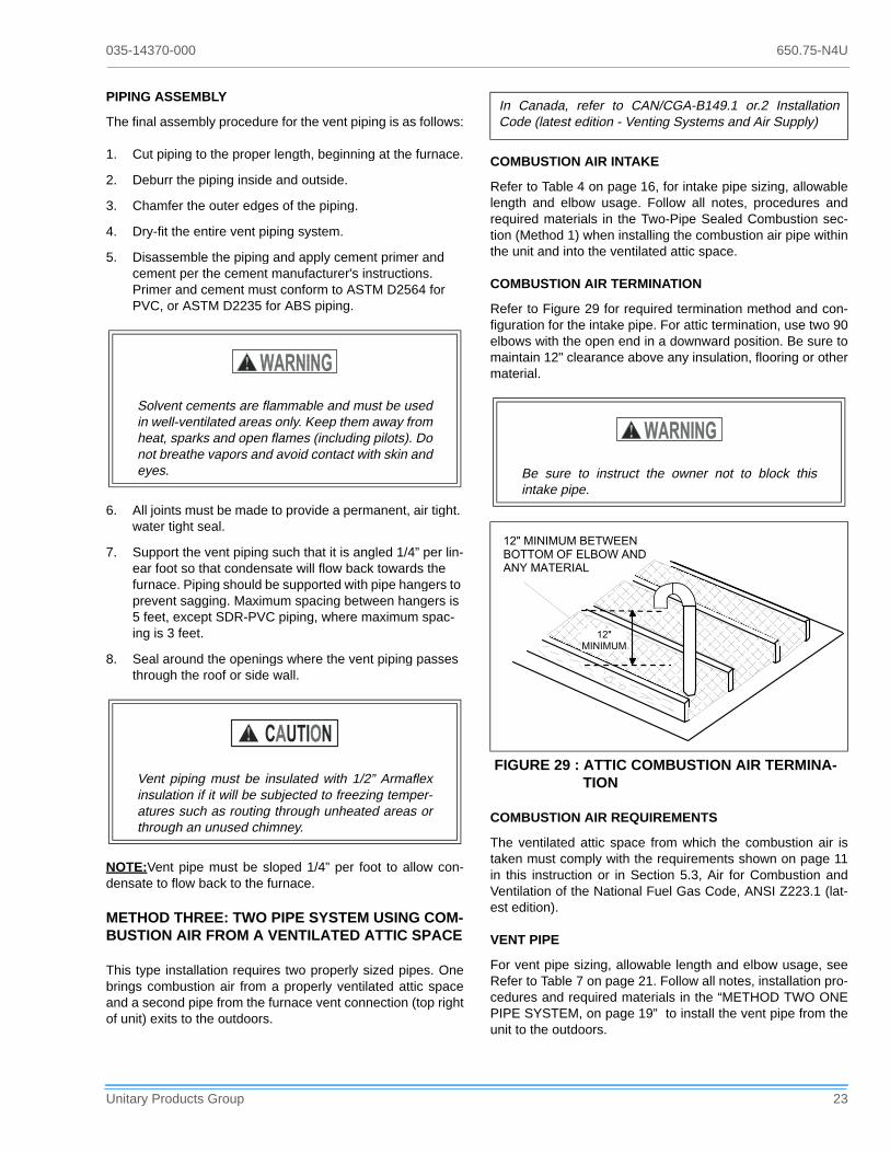
COMBUSTION AIR TERMINATION
Refer to Figure 29 for required termination method and con-figuration for the intake pipe. For attic termination, use two 90elbows with the open end in a downward position. Be sure tomaintain 12" clearance above any insulation, flooring or othermaterial.
COMBUSTION AIR REQUIREMENTS
The ventilated attic space from which the combustion air istaken must comply with the requirements shown on page 11in this instruction or in Section 5.3, Air for Combustion andVentilation of the National Fuel Gas Code, ANSI Z223.1 (lat-est edition).
VENT PIPE
For vent pipe sizing, allowable length and elbow usage, seeRefer to Table 7 on page 21. Follow all notes, installation pro-cedures and required materials in the “METHOD TWO ONEPIPE SYSTEM, on page 19” to install the vent pipe from theunit to the outdoors.
Solvent cements are flammable and must be usedin well-ventilated areas only. Keep them away fromheat, sparks and open flames (including pilots). Donot breathe vapors and avoid contact with skin andeyes.
Vent piping must be insulated with 1/2” Armaflexinsulation if it will be subjected to freezing temper-atures such as routing through unheated areas orthrough an unused chimney.
In Canada, refer to CAN/CGA-B149.1 or.2 InstallationCode (latest edition - Venting Systems and Air Supply)
FIGURE 29 : ATTIC COMBUSTION AIR TERMINA-TION
Be sure to instruct the owner not to block thisintake pipe.
� � � � � � � � � � � � � � �
� � � � � � � � � � � � �
� � � � � � � � � � �
� � �
� � � � � � �

650.75-N4U 035-14370-000
24 Unitary Products Group
VENT TERMINATION
The vent pipe termination must be installed within the allow-able locations shown in Figure 24 and Section 7.8 in theNational Fuel Gas Code, ANSI Z223.1 (current edition). Fol-low all local agency and utility requirements if more restrictivethan those shown. Vent termination must be as shown in Fig-ure 27through Figure 28.
HORIZONTAL VENT APPLICATIONS
If installing a horizontal venting system through any uncondi-tioned space such as an attic or crawl space, it is recom-mended, but not required, that a vent drain be added to thevent pipe to prevent the accumulation of excess condensatein the inducer motor during operational cycles. (Refer to Fig-ures 30 and 31).
To install the vent drain, complete the following steps:
1. Place a tee of the proper diameter for the vent system being installed (2" or 3") in the horizontal run closest to the furnace.
2. Place a reducer bushing of proper diameter in the stem portion of the tee. The recommended size for the reducer is 5/8”.
3. Place a piece of 5/8” diameter or other selected size pipe a minimum of 3" long into the reducer to serve as a nip-ple.
NOTE:Tee, reducer and nipple must be properly cementedtogether using the appropriate method and materials speci-fied in the Combustion Air Intake/Vent Connections section ofthese instructions.
4. Connect a piece of flexible drain tubing such as EPDM rubber, Vinyl or PVC to the nipple.
5. Loop the drain tubing to provide a trap.
6. Connect the discharge end of the drain tube to the con-densate disposal system externally to the furnace.
CONDENSATE PIPING
The condensate drain connection is packed in the furnace forfield installation. It consists of a formed hose with a 1/2” NPTmale connection. A 1/2” FM x 3/4” PVC slip coupling is pro-vided.
In Canada, refer to CAN/CGA-B149.1 or .2 Installation Code (lat-est edition - Venting Systems and Air Supply)
FIGURE 30 : HORIZONTAL VENT DRAIN - UPFLOW MODELS P*UR/FG9-UP/G9T-UP
FIGURE 31 : HORIZONTAL VENT DRAIN - DOWNFLOW/HORIZONTAL MODELS P*DH/FG9-DH/G9T-DH
035-14370-000 650.75-N4U
Unitary Products Group 25
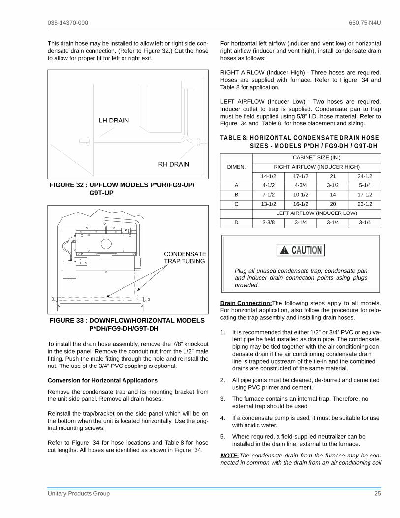
This drain hose may be installed to allow left or right side con-densate drain connection. (Refer to Figure 32.) Cut the hoseto allow for proper fit for left or right exit.
To install the drain hose assembly, remove the 7/8” knockoutin the side panel. Remove the conduit nut from the 1/2” malefitting. Push the male fitting through the hole and reinstall thenut. The use of the 3/4” PVC coupling is optional.
Conversion for Horizontal Applications
Remove the condensate trap and its mounting bracket fromthe unit side panel. Remove all drain hoses.
Reinstall the trap/bracket on the side panel which will be onthe bottom when the unit is located horizontally. Use the orig-inal mounting screws.
Refer to Figure 34 for hose locations and Table 8 for hosecut lengths. All hoses are identified as shown in Figure 34.
For horizontal left airflow (inducer and vent low) or horizontalright airflow (inducer and vent high), install condensate drainhoses as follows:
RIGHT AIRLOW (Inducer High) - Three hoses are required.Hoses are supplied with furnace. Refer to Figure 34 andTable 8 for application.
LEFT AIRFLOW (Inducer Low) - Two hoses are required.Inducer outlet to trap is supplied. Condensate pan to trapmust be field supplied using 5/8” I.D. hose material. Refer toFigure 34 and Table 8, for hose placement and sizing.
Drain Connection:The following steps apply to all models.For horizontal application, also follow the procedure for relo-cating the trap assembly and installing drain hoses.
1. It is recommended that either 1/2” or 3/4” PVC or equiva-lent pipe be field installed as drain pipe. The condensate piping may be tied together with the air conditioning con-densate drain if the air conditioning condensate drain line is trapped upstream of the tie-in and the combined drains are constructed of the same material.
2. All pipe joints must be cleaned, de-burred and cemented using PVC primer and cement.
3. The furnace contains an internal trap. Therefore, no external trap should be used.
4. If a condensate pump is used, it must be suitable for use with acidic water.
5. Where required, a field-supplied neutralizer can be installed in the drain line, external to the furnace.
NOTE:The condensate drain from the furnace may be con-nected in common with the drain from an air conditioning coil
FIGURE 32 : UPFLOW MODELS P*UR/FG9-UP/G9T-UP
FIGURE 33 : DOWNFLOW/HORIZONTAL MODELS P*DH/FG9-DH/G9T-DH
��������
��������
� � � � � � � � � �� � � � � � � �
TABLE 8: HORIZONTAL CONDENSATE DRAIN HOSE SIZES - MODELS P*DH / FG9-DH / G9T-DH
DIMEN.
CABINET SIZE (IN.)
RIGHT AIRFLOW (INDUCER HIGH)
14-1/2 17-1/2 21 24-1/2
A 4-1/2 4-3/4 3-1/2 5-1/4
B 7-1/2 10-1/2 14 17-1/2
C 13-1/2 16-1/2 20 23-1/2
LEFT AIRFLOW (INDUCER LOW)
D 3-3/8 3-1/4 3-1/4 3-1/4
Plug all unused condensate trap, condensate panand inducer drain connection points using plugsprovided.

650.75-N4U 035-14370-000
26 Unitary Products Group
if allowed by local code. Follow the instructions with the coilfor trapping the drain.
SAFETY CONTROLS
Control Circuit Fuse:A 3 amp. fuse is provided to protectthe 24 volt transformer from overload caused by control cir-cuit wiring errors. This is an ATO 3, automotive type fuse andis located in the unit wiring harness between the controltransformer and the furnace control.
Blower Door Safety Switch:This unit is equipped with anElectrical Interlock Switch mounted in the blower compart-ment. This switch interrupts all power at the unit when thepanel covering the blower compartment is removed.
Electrical supply to this unit is dependent upon the panel thatcovers the blower compartment being in place and properlypositioned.
Rollout Switch Controls:This control is mounted on theburner box assembly. If the temperature in the burner com-partment exceeds its set point, the igniter control and the gasvalve are de-energized. The operation of this control indi-cates a malfunction in the combustion air blower, heatexchanger or a blocked vent pipe connection. Correctiveaction is required. This is a manual reset control and must bereset before operation can continue.
Pressure Switches:This furnace is supplied with pressureswitches which monitor the flow through the combustion air/vent piping system. These switches de-energize the ignition
FIGURE 34 : HORIZONTAL APPLICATION CONDENSATE DRAIN CONNECTION (MODELS P*DH / FG9-DH / G9T-DH)
� ��
� � � � � � � � � � �� � � � � � � � � � � � �
�
�
� � � � � � � � � � � � � � � � � � � � � � � �� � � � � � � � � � � � � � � � � �
� � � � � � � � � � � � � � � � � � � � � � �� � � � � � � � � � � � � � � � � �
� � � � � � � � � � � � � � � � � � � � � � � �� � � � � � � � � � � � � � � � � � �
� � � �� � � � � �� � � � �
�
��
� � � � � � � � � � � � � � � � � � � � � � � � � � � � � � � � � � � � � � � � � �
� � � � � � � � � � � � � � � � � � � � � � � � � � � � � � � � � � � � � � � � � �
� � � � � � � � � � �� � � � � � � � � � � �
� � � �� � � � � �� � � � �
Blower and burner must never be operated withoutthe blower panel in place.
Main power to the unit must still be interrupted atthe main power disconnect switch before any ser-vice or repair work is to be done to the unit. Do notrely upon the interlock switch as a main power dis-connect.

035-14370-000 650.75-N4U
Unitary Products Group 27
control module and the gas valve if any of the following condi-tions are present. Refer to Figure 35 for tubing connections.
1. Blockage of combustion air piping or terminal. (1LP)
2. Blockage of vent piping or terminal (1LP).
3. Failure of combustion air blower motor (1LP).
4. Blockage of condensate drain piping:
• Upflow units (1LP)• Downflow/Horizontal Units
• Downflow (1LP)• Horizontal Left (1LP)• Horizontal Right (2LP)
Limit Control
There are high temperature limit control(s) located on the fur-nace vestibule panel near the gas valve. These are automaticreset control and provides over temperature protection due toreduced airflow, such as a dirty filter.
Auxiliary Limit Controls
Downflow/horizontal units have a single limit switch muntedon the blower assembly. This is a manual reset control andgives high temperature protection in the event of a blowermotor failure.
START-UP AND ADJUSTMENTS
The initial start-up of the furnace requires the following addi-tional procedures:
1. When the gas supply is initially connected to the furnace, the gas piping may be full of air. In order to purge this air, it is recommended that the ground union be loosened until the odor of gas is detected. When gas is detected, immediately retighten the union and check for leaks. Allow five minutes for any gas to dissipate before con-tinuing with the start-up procedure.
2. The condensate trap must be filled with water before put-ting the furnace into operation. The recommended pro-cedure is as follows:
a. Disconnect the condensate drain hose from theinduced draft blower discharge.
b. Elevate this hose and fill with water using a funnel.
c. Replace the condensate drain hose and clamps.
NOTE:If this procedure is not followed, the unit may not prop-erly drain on initial start up.
3. All electrical connections made in the field and in the fac-tory should be checked for proper tightness.
IGNITION SYSTEM SEQUENCE
1. Turn the gas supply ON at external valve and main gas valve.
2. Set the thermostat above room temperature to call for heat.
FIGURE 35 : PRESSURE SW ITCH TUBING ROUTING
UPFLOW
1LP
DOWNFLOW / HORIZONTAL
1LP2LP
Be sure proper ventilation is available to dilute andcarry away any vented gas.
Perform the following procedures only after thecondensate trap has been properly piped to adrain connection using the procedure in thisinstruction.
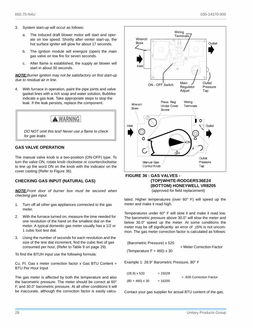
650.75-N4U 035-14370-000
28 Unitary Products Group
3. System start-up will occur as follows:
a. The induced draft blower motor will start and oper-ate on low speed. Shortly after venter start-up, thehot surface igniter will glow for about 17 seconds.
b. The ignition module will energize (open) the maingas valve on low fire for seven seconds.
c. After flame is established, the supply air blower willstart in about 30 seconds.
NOTE:Burner ignition may not be satisfactory on first start-updue to residual air in line.
4. With furnace in operation, paint the pipe joints and valve gasket lines with a rich soap and water solution, Bubbles indicate a gas leak. Take appropriate steps to stop the leak. If the leak persists, replace the component.
GAS VALVE OPERATION
The manual valve knob is a two-position (ON-OFF) type. Toturn the valve ON, rotate knob clockwise or counterclockwiseto line up the word ON on the knob with the indicator on thecover casting (Refer to Figure 36).
CHECKING GAS INPUT (NATURAL GAS)
NOTE:Front door of burner box must be secured whenchecking gas input.
1. Turn off all other gas appliances connected to the gas meter.
2. With the furnace turned on, measure the time needed for one revolution of the hand on the smallest dial on the meter. A typical domestic gas meter usually has a 1/2 or 1 cubic foot test dial.
3. Using the number of seconds for each revolution and the size of the test dial increment, find the cubic feet of gas consumed per hour, (Refer to Table 9 on page 29).
To find the BTUH input use the following formula:
Cu. Ft. Gas x meter correction factor x Gas BTU Content =BTU Per Hour Input
The gas meter is affected by both the temperature and alsothe barometric pressure. The meter should be correct at 60°F, and 30.0" barometric pressure. At all other conditions it willbe inaccurate, although the correction factor is easily calcu-
lated. Higher temperatures (over 60° F) will speed up themeter and make it read high.
Temperatures under 60° F will slow it and make it read low.The barometric pressure above 30.0" will slow the meter andbelow 30.0" speed up the meter. At some conditions themeter may be off significantly. an error of +5% is not uncom-mon. The gas meter correction factor is calculated as follows:
Example 1: 28.9" Barometric Pressure, 80° F
Contact your gas supplier for actual BTU content of the gas.
DO NOT omit this test! Never use a flame to checkfor gas leaks.
FIGURE 36 : GAS VALVES - (TOP) WHITE-RODGERS 36E24 (BOTTOM) HONEYWELL VR8205 (approved for field replacement)
(Barometric Pressure) x 520 = Meter Correction Factor
(Temperature F + 460) x 30
(28.9) x 520 = 15028= .928 Correction Factor
(80 + 460) x 30 = 16200
��������������
�����
�������������������
����������
���� ���������
�����
��������������
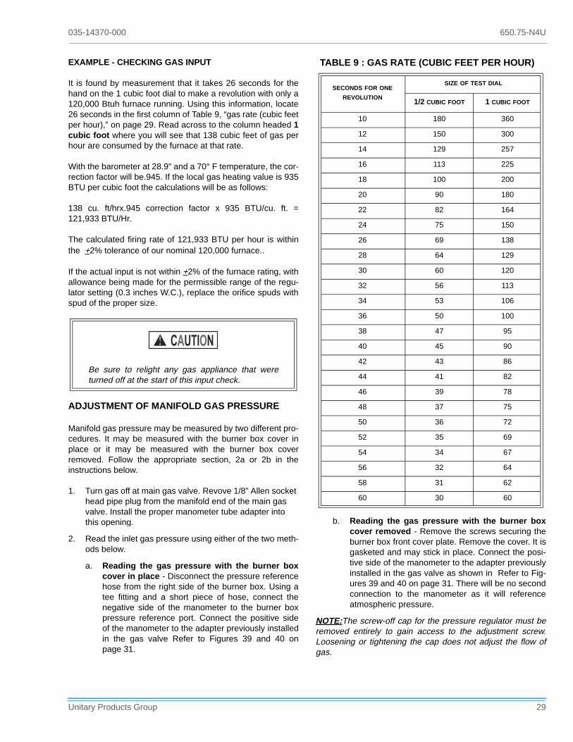
035-14370-000 650.75-N4U
Unitary Products Group 29
EXAMPLE - CHECKING GAS INPUT
It is found by measurement that it takes 26 seconds for thehand on the 1 cubic foot dial to make a revolution with only a120,000 Btuh furnace running. Using this information, locate26 seconds in the first column of Table 9, “gas rate (cubic feetper hour),” on page 29. Read across to the column headed 1cubic foot where you will see that 138 cubic feet of gas perhour are consumed by the furnace at that rate.
With the barometer at 28.9" and a 70° F temperature, the cor-rection factor will be.945. If the local gas heating value is 935BTU per cubic foot the calculations will be as follows:
138 cu. ft/hrx.945 correction factor x 935 BTU/cu. ft. =121,933 BTU/Hr.
The calculated firing rate of 121,933 BTU per hour is withinthe +2% tolerance of our nominal 120,000 furnace..
If the actual input is not within +2% of the furnace rating, withallowance being made for the permissible range of the regu-lator setting (0.3 inches W.C.), replace the orifice spuds withspud of the proper size.
ADJUSTMENT OF MANIFOLD GAS PRESSURE
Manifold gas pressure may be measured by two different pro-cedures. It may be measured with the burner box cover inplace or it may be measured with the burner box coverremoved. Follow the appropriate section, 2a or 2b in theinstructions below.
1. Turn gas off at main gas valve. Revove 1/8” Allen socket head pipe plug from the manifold end of the main gas valve. Install the proper manometer tube adapter into this opening.
2. Read the inlet gas pressure using either of the two meth-ods below.
a. Reading the gas pressure with the burner boxcover in place - Disconnect the pressure referencehose from the right side of the burner box. Using atee fitting and a short piece of hose, connect thenegative side of the manometer to the burner boxpressure reference port. Connect the positive sideof the manometer to the adapter previously installedin the gas valve Refer to Figures 39 and 40 onpage 31.
b. Reading the gas pressure with the burner boxcover removed - Remove the screws securing theburner box front cover plate. Remove the cover. It isgasketed and may stick in place. Connect the posi-tive side of the manometer to the adapter previouslyinstalled in the gas valve as shown in Refer to Fig-ures 39 and 40 on page 31. There will be no secondconnection to the manometer as it will referenceatmospheric pressure.
NOTE:The screw-off cap for the pressure regulator must beremoved entirely to gain access to the adjustment screw.Loosening or tightening the cap does not adjust the flow ofgas.
Be sure to relight any gas appliance that wereturned off at the start of this input check.
TABLE 9 : GAS RATE (CUBIC FEET PER HOUR)
SECONDS FOR ONE REVOLUTION
SIZE OF TEST DIAL
1/2 CUBIC FOOT 1 CUBIC FOOT
10 180 360
12 150 300
14 129 257
16 113 225
18 100 200
20 90 180
22 82 164
24 75 150
26 69 138
28 64 129
30 60 120
32 56 113
34 53 106
36 50 100
38 47 95
40 45 90
42 43 86
44 41 82
46 39 78
48 37 75
50 36 72
52 35 69
54 34 67
56 32 64
58 31 62
60 30 60

650.75-N4U 035-14370-000
30 Unitary Products Group
3. Refer to Figure 36 on page 28, for location of pressure regulator adjustment cap and screw on main gas valve.
4. Turn gas and electrical supplies ON. Start furnace and observe manifold pressure on manometer.
5. Adjust manifold pressure by adjusting gas valve regula-tor screw for the appropriate gas per the following:.
If gas valve regulator is turned in, or clockwise, manifoldpressure is increased. If screw is turned out, or counterclock-wise, manifold pressure will decrease.
Turn the electrical and gas supplies back on, and with theburners in operation, check for gas leakage around the plugwith a soap and water solution.
ADJUSTMENT OF TEMPERATURE RISE
The temperature rise, or temperature difference between thereturn air and the heated air from the furnace, must be withinthe range shown on the furnace rating plate. Application limi-tations are shown in Table 1 or 2. After the temperature risehas been determined, the cfm can be calculated.
After about 20 minutes of operation, determine the furnacetemperature rise. Take readings of both the return air and theheated air in the ducts, about six feet from the furnace wherethey will not be affected by radiant heat.
Increase the blower speed to decrease the temperature rise;decrease the blower speed to increase the rise.
All direct-drive blowers have multi-speed motors. The blowermotor speed taps are located in the control box in the blowercompartment. Refer to Figure 37, and the unit wiring label tochange the blower speed.
You may select a heating speed and a cooling speed. Theymay be the same speed or a different speed.To use the samespeed tap for heating and cooling, the heat terminal and coolterminal must be connected using a jumper wire and con-nected to the desired motor lead. Place all unused motorleads on Park terminals. Two Park terminals are provided. .
ADJUSTMENT OF FAN-OFF CONTROL SETTINGS
This furnace is equipped with a time-on/time-off heating fancontrol. The fan on is fixed at 30 seconds. The fan off is fieldadjustable from 60 to 180 seconds. The fan off is factory setto 60 seconds. Adjust the off time by repositioning the fan offswitches. (Refer to Figure 37.)
The fan-off setting must be long enough to adequately coolthe furnace, but not so long that cold air is blown into theheated space. The fan-off timing may be adjusted by settingthe option switches located (Refer to Figure 37) on the con-trol board as follows:
Natural Gas ..............................................................3.5” W.C.Propane (LP) Gas ....................................................10.0” W.C.
If manifold pressure is too high, an over-fire condi-tion exists which could cause heat exchanger fail-ure. If the manifold pressure is too low, sootingand eventual clogging of the heat exchanger couldoccur.
Once the correct gas pressure to the burners hasbeen established, turn the gas valve knob to OFFand turn the electrical supply switch to OFF; thenremove the pressure tap at the gas valve and re-install the plug, using a compound (on the threads)resistant to the action of LP gases. Replace theburner box front cover or the pressure referencehose.
Be sure that gas valve regulator cap and burnerbox to gas valve pressure reference hose is recon-nected.
Do not energize more than one motor speed at atime or damage to the motor will result.
FIGURE 37 : TYPICAL HEAT/COOL SPEED TAP CONNECTIONS
To Delay Fan-Off By:
Set Switch
1 2
60 Sec. ON ON
90 Sec. OFF ON
120 Sec. ON OFF
180 Sec. OFF OFF

035-14370-000 650.75-N4U
Unitary Products Group 31
For units using a Texas Instruments control, connect thejumper at the desired off timing. Refer to Figure 37 onpage 30, 60 second off timing shown.
ACCESSORY CONNECTIONS
The furnace control will allow power switching control of vari-ous accessories. Refer to Figure 38.
Electronic Air Cleaner Connection
Two 1/4” spade terminals (EAC and EAC N) for electronic aircleaner connections are located on the control board. Theterminals provide 120 VAC (1.0 amp maximum) during circu-lating blower operation.
Humidifier Connection
Two 1/4” spade terminals (HUM and HUM N) for humidifierconnections are located on the control board. The terminalsprovide 120 VAC (1.0 amp maximum) during heat speedoperation of the circulating blower..
Do not exceed 1.0 amp loading.
FIGURE 38 : ACCESSORY CONNECTIONS
!"�
#�$
#�$
!"�
%%&�' (�#(#$�� ��$����$(#��#�
#�$�! �
!"��! �
�()
�()
�!�
�!�
%%&�' (�!"��*���#�
����$!#*$��$"���
�#"���(�
FIGURE 39 : UPFLOW MODELS (P*UR/ FG9-UP / G9T-UP) - READING GAS PRESSUREWITH BURNER BOX COVER IN PLACE WITH BURNER BOX COVER REMOVED
FIGURE 40 : DOWNFLOW/HORIZONTAL MODELS (P*DH/ FG9-DH / G9T-DH) - READING GAS PRESSUREWITH BURNER BOX COVER IN PLACE WITH BURNER BOX COVER REMOVED
+��'�('#
"��"�#��� �#�#�
�"��#��� ,���!�$ '#�
-.&���.���#��$ ("��+�����#��"�#
�! ��
�"��#��� ,��#��"�#
�#�#�#�$#�! �#
"�(#���#��"�#
���
/&0-1%2%1-0&/
�##������+
/&0-1%2%1-0&/
+��'�('#
"��"�#��� �#�#�
�"��#��� ,���!�$ '#���#� '#*
-.&���.���#��$ ("��+�����#��"�#
�! ��
�"��#��� ,��#��"�#�#�#�#�$#�! �#3� ��"�#*4
"�(#���#��"�#
���
�������������
�
� � �
� � � � � � � � � � �
� � � � � � � � �� � � � � � � � �
� � � � � � �� � � � � � � � � �� � � � � �
� � � �
� � � � � � � � �� � � � � � � � � � � �
� � � � �� � � � � �
� � � � � � � � �
�������������
�
� � �
� � � � � � � � � � �
� � � � � � � � �� � � � � � � � � � � � � � �
� � � � � � �� � � � � � � � � �� � � � � �
� � � �
� � � � � � � � �� � � � � � � � � � � � � � � � � � !
� � � � �� � � � � �

650.75-N4U 035-14370-000
32 Unitary Products Group
FURNACE ACCESSORIES
ELECTRICAL
2TH07700124 Single Stage Thermostat, One-Stage Heat/One-Stage Cool
2TH13700424 Deluxe 24V Thermostat - with heat only subbase (must be used w/subbase 2TB17700424)
2TB17700424 Subbase (24V) One-Stage Heat/One-Stage Cool
2ET07700224 Programmable, Electronic Thermostat, One-Stage Heat/One-Stage Cool
2TC03700124 Twinning Control
NON-ELECTRICAL
1NP0347 Propane (LP) Conversion Kit
1NP0349 Propane (LP) Conversion Kit
1PS0306
High Altitude Pressure Switch (See Form 650.75-N2.1V for proper application)
1PS0307
1PS0308
1PS0309
1PS0310
1SR0302 External Side Filter Rack (6-Pack)
1BR0314 External Bottom Filter Rack - Cabinet “A”
1BR0317 External Bottom Filter Rack - Cabinet “B”
1BR0321 External Bottom Filter Rack - Cabinet “C”
1BR0324 External Bottom Filter Rack - Cabinet “D”
1CT0302 Concentric Vent Termination - 2” Vent Pipe
1CT0303 Concentric Vent Termination - 3” Vent Pipe
1CB0314 Combustible Floor Base - Cabinet “A”
1CB0317 Combustible Floor Base - Cabinet “B”
1CB0321 Combustible Floor Base - Cabinet “C”
1CB0324 Combustible Floor Base - Cabinet “D”
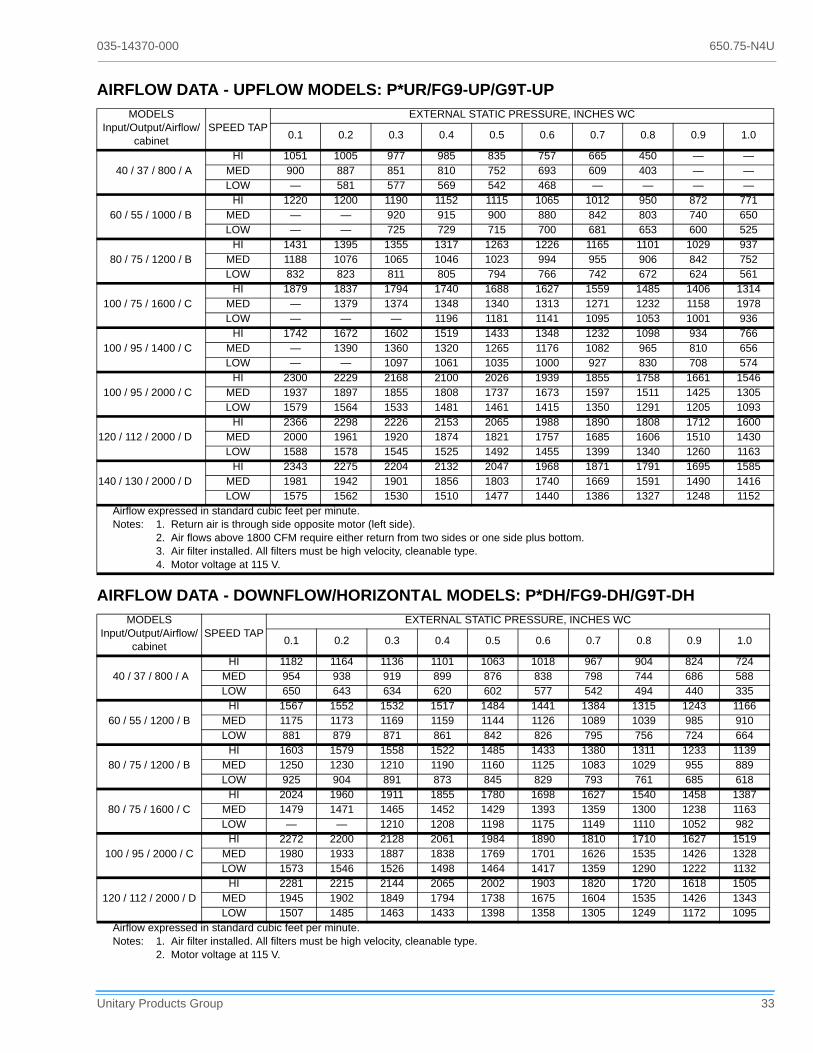
035-14370-000 650.75-N4U
Unitary Products Group 33
AIRFLOW DATA - UPFLOW MODELS: P*UR/FG9-UP/G9T-UPMODELS
Input/Output/Airflow/cabinet
SPEED TAPEXTERNAL STATIC PRESSURE, INCHES WC
0.1 0.2 0.3 0.4 0.5 0.6 0.7 0.8 0.9 1.0
40 / 37 / 800 / AHI 1051 1005 977 985 835 757 665 450 — —
MED 900 887 851 810 752 693 609 403 — —LOW — 581 577 569 542 468 — — — —
60 / 55 / 1000 / BHI 1220 1200 1190 1152 1115 1065 1012 950 872 771
MED — — 920 915 900 880 842 803 740 650LOW — — 725 729 715 700 681 653 600 525
80 / 75 / 1200 / BHI 1431 1395 1355 1317 1263 1226 1165 1101 1029 937
MED 1188 1076 1065 1046 1023 994 955 906 842 752LOW 832 823 811 805 794 766 742 672 624 561
100 / 75 / 1600 / CHI 1879 1837 1794 1740 1688 1627 1559 1485 1406 1314
MED — 1379 1374 1348 1340 1313 1271 1232 1158 1978LOW — — — 1196 1181 1141 1095 1053 1001 936
100 / 95 / 1400 / CHI 1742 1672 1602 1519 1433 1348 1232 1098 934 766
MED — 1390 1360 1320 1265 1176 1082 965 810 656LOW — — 1097 1061 1035 1000 927 830 708 574
100 / 95 / 2000 / CHI 2300 2229 2168 2100 2026 1939 1855 1758 1661 1546
MED 1937 1897 1855 1808 1737 1673 1597 1511 1425 1305LOW 1579 1564 1533 1481 1461 1415 1350 1291 1205 1093
120 / 112 / 2000 / DHI 2366 2298 2226 2153 2065 1988 1890 1808 1712 1600
MED 2000 1961 1920 1874 1821 1757 1685 1606 1510 1430LOW 1588 1578 1545 1525 1492 1455 1399 1340 1260 1163
140 / 130 / 2000 / DHI 2343 2275 2204 2132 2047 1968 1871 1791 1695 1585
MED 1981 1942 1901 1856 1803 1740 1669 1591 1490 1416LOW 1575 1562 1530 1510 1477 1440 1386 1327 1248 1152
Airflow expressed in standard cubic feet per minute.Notes: 1. Return air is through side opposite motor (left side).
2. Air flows above 1800 CFM require either return from two sides or one side plus bottom.3. Air filter installed. All filters must be high velocity, cleanable type.4. Motor voltage at 115 V.
AIRFLOW DATA - DOWNFLOW/HORIZONTAL MODELS: P*DH/FG9-DH/G9T-DHMODELS
Input/Output/Airflow/cabinet
SPEED TAPEXTERNAL STATIC PRESSURE, INCHES WC
0.1 0.2 0.3 0.4 0.5 0.6 0.7 0.8 0.9 1.0
40 / 37 / 800 / AHI 1182 1164 1136 1101 1063 1018 967 904 824 724
MED 954 938 919 899 876 838 798 744 686 588LOW 650 643 634 620 602 577 542 494 440 335
60 / 55 / 1200 / BHI 1567 1552 1532 1517 1484 1441 1384 1315 1243 1166
MED 1175 1173 1169 1159 1144 1126 1089 1039 985 910LOW 881 879 871 861 842 826 795 756 724 664
80 / 75 / 1200 / BHI 1603 1579 1558 1522 1485 1433 1380 1311 1233 1139
MED 1250 1230 1210 1190 1160 1125 1083 1029 955 889LOW 925 904 891 873 845 829 793 761 685 618
80 / 75 / 1600 / CHI 2024 1960 1911 1855 1780 1698 1627 1540 1458 1387
MED 1479 1471 1465 1452 1429 1393 1359 1300 1238 1163LOW — — 1210 1208 1198 1175 1149 1110 1052 982
100 / 95 / 2000 / CHI 2272 2200 2128 2061 1984 1890 1810 1710 1627 1519
MED 1980 1933 1887 1838 1769 1701 1626 1535 1426 1328LOW 1573 1546 1526 1498 1464 1417 1359 1290 1222 1132
120 / 112 / 2000 / DHI 2281 2215 2144 2065 2002 1903 1820 1720 1618 1505
MED 1945 1902 1849 1794 1738 1675 1604 1535 1426 1343LOW 1507 1485 1463 1433 1398 1358 1305 1249 1172 1095
Airflow expressed in standard cubic feet per minute.Notes: 1. Air filter installed. All filters must be high velocity, cleanable type.
2. Motor voltage at 115 V.

650.75-N4U 035-14370-000
34 Unitary Products Group
OPERATION AND MAINTENANCE
SEQUENCE OF OPERATION
The following describes the sequence of operation of the fur-nace. Refer to the schematic wiring diagrams in the back ofthis manual for component location.
CONTINUOUS BLOWER
On cooling/heating thermostats with fan switch, when the fanswitch is set in the ON position, a circuit is completedbetween terminals R and G of the thermostat. The blowermotor is energized through the low heat terminal and runs onthe selected speed. This allows constant air circulation atlower flow rate.
INTERMITTENT BLOWER - COOLING
On cooling/heating thermostats with fan switch, when the fanswitch is set in the auto position and the thermostat calls forcooling, a circuit is completed between the R, Y and G termi-nals.
The motor is energized through the cool fan terminal andruns on the selected speed. The fan off setting is fixed at 60seconds for SEER enhancement.
HEATING CYCLE
When the system switch is set on HEAT and the fan is set onAUTO, and the room thermostat calls for heat, a circuit iscompleted between terminals R and W of the thermostat.When the proper amount of combustion air is being provided,a pressure switch activates the ignition control
The ignition control provides a 17-second warm-up period.The gas valve then opens for seven seconds.
As gas starts to flow and ignition occurs, the flame sensorbegins its sensing function. If a flame is detected within sevenseconds after ignition, normal furnace operation continuesuntil the thermostat circuit between R and W is opened. Afterflame is present for 30 seconds, the circulating blower isenergized.
When the thermostat circuit opens, the ignition control is de-energized. With the ignition control de-energized, the gasflow stops and the burner flames are extinguished. The ven-ter continues to operate for 15 seconds after the gas flowstops.
The blower motor continues to operate for the amount of timeset by the fan-off delay switches located on the control board.The heating cycle is then complete, and the unit is ready forthe start of the next heating cycle.
If flame is not detected within the seven second sensingperiod, the gas valve is de-energized. The control isequipped with a re-try option. This provides a 60 second waitfollowing an unsuccessful ignition attempt (flame notdetected).
After the 60 second wait, the ignition sequence is restartedwith an additional 10 seconds of igniter warm-up time. If thisignition attempt is unsuccessful, one more re-try will be madebefore lockout.
A momentary loss of gas supply, flame blowout, or a shortedor open condition in the flame probe circuit will be sensedwithin 0.8 seconds.
The gas valve will deenergize and the control will restart theignition sequence immediately. Recycles will begin and theburner will operate normally if the gas supply returns, or thefault condition is corrected prior to the last ignition attempt.Otherwise, the control will lockout.
The control will repeat the ignition sequence for a total of tworecycles if flame is lost within the first 10 seconds of estab-lishment.
If flame is established for more than 10 seconds after ignition,the control will clear the ignition attempt (retry) counter. Ifflame is lost after 10 seconds, it will restart the ignitionsequence. This can occur a maximum of five times.
During burner operation, a momentary loss of power of 50milliseconds or longer will drop out the main gas valve. Whenthe power is restored, the gas valve will remain de-energizeand a restart of the ignition sequence will begin immediately
Hot Surface Ignition System
.
Do not attempt to light this furnace by hand (with amatch or any other means). There may be apotential shock hazard from the components of thehot surface ignition system. The furnace can onlybe lit automatically by its hot surface ignition sys-tem.

035-14370-000 650.75-N4U
Unitary Products Group 35
MAINTENANCE
Air Filters
The filters must be checked periodically for dirt accumulation.Dirty filters greatly restrict the flow of air and may cause dam-age to the system.
Clean the filters at least every three months. On new con-struction, check the filters every week for the first four weeks.Inspect the filters every three weeks after that, especially ifthe system is running constantly.
All filters used with the furnace are the high-velocity, clean-able type. Clean these filters by washing in warm water.Make sure to shake all the water out of the filter and have itreasonably dry before installing it in the furnace. Whenreplacing filters, be sure to use the same size and type asoriginally supplied.
Filter Removal - Upflow Models
The ends of the retainer are attached to the rear panel in twometal loops. Refer to Table 42 on page 35. The ends must besqueezed together to free them from the loops. The retainermay then be moved to the new location and the ends insertedin the loops on the rear panel at the new location. Loops areprovided for retainer location to accommodate filter applica-tion on the bottom or either side of the furnace.
To remove a filter from the bottom location, push the closedend of the filter retainer to the left until it clears the lip on thefront of the furnace base, which acts as a catch for theretainer. When the retainer is clear of the flange, it will pivot inthe loops.
Swing the retainer toward the center of the furnace. This willexpose the filter to allow removal. To reinstall the filter, simplyreverse this procedure.
Filter Removal - Downflow Models
1. Turn off electrical power supply to the furnace at discon-nect switch. Remove access doors.
2. Filters are installed in the plenum area above the blower assembly. Filters rest against the side of the plenum wall and are supported in the middle by a frame. Lift filter slightly to dislodge and remove for service.
3. Remove the filter and follow the cleaning instructions above. DO NOT remove the filter stiffener rods, if pro-
FIGURE 41 : FURNACE CONTROL EVENT SCHEDULE
FIGURE 42 : UPFLOW FILTER RETAINER

650.75-N4U 035-14370-000
36 Unitary Products Group
vided. When reinstalling the filter(s) be sure it completely covers the plenum opening.
To reinstall the filters, simply reverse this procedure.
Horizontal Applications
In most horizontal applications the filter is located in thereturn air duct near the furnace or in a filter grille.
Lubrication
Blower motors in these furnaces are permanently lubricatedand do not require periodic oiling.
Blower Care
Even with good filters properly in place, blower wheels andmotors will become dust laden after long months of opera-tion. The entire blower assembly should be inspected annu-ally. If the motor and wheel are heavily coated with dust, theycan be brushed and cleaned with a vacuum cleaner.
The procedure for removing the direct drive blower assemblyfor cleaning is as follows:
1. Disconnect the electrical supply to the furnace and remove remove the access doors.
2. On downflow/horizontal models only, remove the two wires leading to the auxiliary limit mounted on the side opposite the blower motor.
3. On downflow/horizontal models only, remove four top panel screws and lift the top panel enough to disengage and remove the flue chase assembly.
4. Remove blower assembly mounting screws and slide the blower assembly out of the slots in the deck. If the two shipping screws were not previously removed, also remove and discard these two screws located on each front corner of the blower assembly.
5. On downflow models only, note the wire/terminal location and then remove the blower wiring from the furnace con-trol. Remove the protective boot and disconnect run capacitor wires. Remove the screws securing the electri-cal panel to the blower housing. Pull blower assembly out of the unit. When cleaning or servicing the blower assembly, DO NOT remove or change the balance clips on the blower wheel.
6. To reassemble, reverse the procedure, restore power to the furnace and verify operation.
Burner Removal/Cleaning
The main burners should be checked periodically for dirtaccumulation.
If cleaning is required, follow this procedure:
1. Turn off the electrical power to the unit.
2. Turn off the gas supply at the external manual shutoff valve and loosen the ground union joint.
3. Remove the upper access panel and remove the burner box cover.
4. Remove the screws that hold the burner box assembly to the vest panel and remove the assembly.
5. Remove burners from the burner assembly.
6. Burners may be cleaned by rinsing in hot water.
7. Reassemble the burners in the reverse order.
Cleaning the Heat Exchanger
1. Turn off the main manual gas valve external to the fur-nace.
2. Turn off electrical power to the furnace.
3. Remove the upper access panel and remove the burner box cover.
4. Disconnect wires from flame sensor, rollout switch and HSI igniter. Remove igniter carefully, as it is easily bro-ken.
5. Remove the screws that hold the burner box assembly to the vestibule panel and remove the assembly. The upper portion of the heat exchanger will now be exposed.
6. Remove the upper cover plate at the top of the furnace. Remove the internal baffle.
7. The upper portion of the heat exchanger is now exposed.
8. With a long flexible wire brush, clean inside each tube at both the top and bottom. The brush must pass around the rear heat exchanger tubes. Vacuum loose scale and dirt from each tube.
When replacing filters, DO NOT use a type withexcessively high pressure drop. Some high effi-ciency filters available will cause the furnace tooperate improperly and could result in a safetyhazard.
Label all wires prior to disconnection when servic-ing controls. Wiring errors can cause improper anddangerous operation. Verify proper operation afterservicing.
035-14370-000 650.75-N4U
Unitary Products Group 37
9. Clean - vacuum all burners.
10. Replace all components in reverse order. Reconnect all wiring.
11. Restore electrical power and gas supply to the furnace.
12. Check furnace operation.
Cleaning the Secondary Heat Exchanger
1. Follow steps 1 thru 10 under Cleaning the Primary Heat Exchanger.
2. Remove the vent piping from the venter housing. Discon-nect the drain lines from the venter and from the conden-sate drain pan. Remove the venter blower and the condensate pan. The turbulators can then be gently removed from the secondary heat exchanger.
3. With a stiff wire brush, brush out loose scale or soot.
4. Vacuum the secondary heat exchanger.
5. Finish the cleaning procedure by following steps 10 thru 12 under Cleaning the Primary Heat Exchanger.
Vent/Air Intake
Should it be necessary to service the vent/air intake system,the manufacturer recommends this service be conducted bya qualified service agency.
The operation of this appliance requires the reassembly andresealing of the vent/air intake system as specified on Page11.
TROUBLESHOOTING
The following visual checks should be made before trouble-shooting:
1. Check to see that the power to the furnace and the igni-tion control module is ON.
2. The manual shutoff valves in the gas line to the furnace must be open.
3. Make sure all wiring connections are secure.
4. Review the sequence of operation.
Start the system by setting the thermostat above the roomtemperature. Observe the system's response. Then use the
troubleshooting section in this manual to check the system'soperation..
FURNACE CONTROL DIAGNOSTICS
The furnace has built-in, self diagnostic capability. If a systemproblem occurs, a fault code is shown by a blinking LED. It islocated behind a clear view port in the blower compartmentdoor. DO NOT remove the furnace blower compartmentpanel OR turn off furnace power as either action will clear thecontrol's memory of the fault.
The control continuously monitors its own operation and theoperation of the system. If a failure occurs, the LED will indi-cate the failure code. If the failure is internal to the control, thelight will stay on continuously. In this case, the entire controlshould be replaced as the control is not field repairable.
If the sensed failure is in the system (external to the control),the LED will flash in the following flash-pause sequences toindicate failure status.
Flash sequence codes 2 thru 9 are as follows. LED will turnon for 1/4 second and off for 1/4 second. This pattern will berepeated the number of times equal to the code. For exam-ple, six on flashes equals a number 6 fault code.
All flash code sequences are broken by a 2 second off period
.
CONTINUOUS FLASHING (1 sec on - 1 sec off):This indi-cates that flame was sensed when there was not a call forheat. With this fault code the control will also turn on both theinducer motor and supply air blower. This fault would typically
POWER SUPPLY POLARITY - 50A50-241 ControlOnly If the power supply polarity is reversed, the fol-lowing unit operation will occur. On a call for heat, theinducer will run, the HSI will glow and the gas valve willenergize and the burners will ignite. The burners willimmediately extinguish and the unit will recycle. This willoccur 3 times and then the unit will lockout. A “7” flashcode will be displayed. This code means the flame couldnot be established. This occurs because the control can-not sense flame with the power supply polarity reversed.
50A50-241 IGNITION CONTROL (P/N 031-01266-000) Normal flame sense current is approximately
2.0 microamps DC (µa)
Low flame signal control lockout point is
0.15 microamps (DC (µa)

650.75-N4U 035-14370-000
38 Unitary Products Group
be caused by a gas valve that leaks through or is slow clos-ing.
2 FLASH:This indicates that the normally open pressureswitch contacts are stuck in the closed position. The controlconfirms these contacts are open at the beginning of eachheat cycle. This would indicate a faulty pressure switch ormis-wiring.
3 FLASH:This indicates the normally open pressure switchcontact did not close at the beginning of the heat cycle. Thiscould be caused by a number of problems; faulty inducer,blocked vent pipe, high winds at vent terminal, broken pres-sure switch hose or faulty pressure switch.
4 FLASH:This indicates the auxiliary limit switch has openedits normally closed contacts. With this fault code the controlwill operate the supply air blower and inducer. This conditionmay be caused by: dirty filter, improperly sized duct system,incorrect blower speed setting, incorrect firing rate or faultyblower motor.
5 FLASH:This fault is indicated if the normally closed con-tacts in the rollout switch opens. The rollout control is manu-ally reset. If it has opened, check for proper combustion air,proper inducer operation, primary heat exchanger failure orburner problem. Be sure to reset the switch after correctingthe failure condition.
6 FLASH:This indicates that after the unit was operating, thepressure switch opened 5 times during the call for heat. Thiscould be caused by a number of problems; blocked vent orcombustion air intake, high winds at vent terminal, faultyinducer, cracked pressure switch hose, or a blockage in thecondensate drainage system.
7 FLASH:This fault code indicates that flame could not beestablished. This no-light condition occurred 3 times duringthe call for heat before locking out. This may be caused bylow gas pressure, faulty gas valve, faulty hot surface igniteror burner problem.
8 FLASH:This fault is indicated if the flame is lost 5 timesduring the heating cycle. This could be caused by low gaspressure or faulty gas valve.
LED ON CONSTANTLY:This indicated an internal fault in thefurnace control discovered during its self-check procedure.Replace the control.
60 MINUTE AUTOMATIC RESET FROM LOCKOUT:Thiscontrol includes a watchdog type circuit that will reset from alockout condition after 60 minutes. Operational faults 6, 7 & 8will be reset. This provides protection to an unoccupied struc-ture if a temporary conditions exists causing a unit malfunc-tion. An example would be a low incoming gas supplypressure condition preventing unit operation. When the gaspressure was restored, at some point the watchdog wouldrestart the unit and provide heat for the house.
NOTE:The control will blink one time when initially powered.This is normal and not an indication of any malfunction.
RESET FROM LOCKOUT:To reset the control from any lock-out condition break the line voltage supply or 24 volt signalfrom the thermostat for 30 seconds.
Do not try to repair controls. Replace defectivecontrols with Source 1 Parts.
Never adjust pressure switch to allow furnaceoperation.
Never jump pressure switch or rewire in anattempt to allow furnace operation. To do so willallow furnace to operate under potentially hazard-ous conditions.

035-14370-000 650.75-N4U
Unitary Products Group 39
WIRING DIAGRAM - UPFLOW MODELS: P*UR / FG9-UP / G9T-UP
NOTE: THE FURNACE’S CONTROL SYSTEM DEPENDS ON CORRECT POLARITY OF THE POWER SUPPLY.

Subject to change without notice. Printed in U.S.A.Copyright © by Unitary Products Group 1999. All rights reserved. Supersedes: 650.75-N4U (599) 650.75-N1U (899)
Unitary 5005 York NormanProduct Drive OKGroup North 73069
WIRING DIAGRAM - DOWNFLOW/HORIZONTAL MODELS: P*DF / FG9-DH / G9T-DH NOTE: THE FURNACE’S CONTROL SYSTEM DEPENDS ON CORRECT POLARITY OF THE POWER SUPPLY.