Embed Size (px)
Citation preview


FUNDAMENTALS OFREMOVABLE PARTIAL PROSTHODONTIC DESIGN
Kenneth R. McHenry, D.D.S., M.S.Terrence McLean, D.D.S.
Contributing Authors: Robert E. Ogle, D.D.S.Illustrations: John A. Nyquist, M.S. CMI

TABLE OF CONTENTS
CHAPTER 1 - SURVEYING Surveying............................................................. 1-2Diagnostic Survey.................................................... 1-5Tripoding.............................................................. 1-10CHAPTER 2 - REFERENCEBasic Components of a Partial Denture........................... 2-1 I. Methods of Partial Denture Retention..................... 2-1 II. Support Units - Rests......................................... 2-10 III. Major Connector.............................................. 2-12 - Types of Mandibular Major Connectors................. 2-19 IV. Minor Connectors............................................. 2-23 V. Indirect Retainers............................................ 2-25 VI. Lattice Work.................................................. 2-26 VII. Acrylic Base.................................................. 2-29 VIII. Teeth......................................................... 2-29CHAPTER 3 - PRELIMINARY DESIGNProcedure 1. resurvey........................................................ 3-2 2. marking the cast.............................................. 3-2 3. design........................................................... 3-5CHAPTER 4 - TOOTH MODIFICATIONS I.ToothModifications........................................... 4-1 SequenceofAbutmentModifications.................... 4-2 1.guidingplanes............................................ 4-3 2.toothsurfacestoaccomodateclaspform........... 4-5 3.interferences............................................. 4-8 4.esthetics................................................... 4-10 5.rests........................................................ 4-12 6.modificationofrestsforembrasureclasps...........4-15 II.Criteria.........................................................4-22 1.fortoothmodification(maxillary)..................... 4-22 2.fortoothmodification(mandibular)...................4-23 3.forrests.................................................... 4-24
CHAPTER 5 - MASTER CASTDrawing the Final Design on the Master Cast............................... 5-1Components of the Drawing................................................... 5-2Color Code for the Drawing................................................... 5-5Criteria for the Drawings 1. for major and minor connections...................................... 5-6 2. for clasp assemblies...................................................... 5-7CHAPTER 6 - WORK AUTHORIZATIONContent of a Work Authorization.............................................. 6-2Work Detail....................................................................... 6-3RelationshipBetweenDentistandTechnician.............................. 6-4Criteria for Work Authorization................................................ 6-5CHAPTER 7 - USE OF CAST RESTORATIONS ON ABUTMENT TEETHSequence.......................................................................... 7-2CHAPTER 8 - CUSTOM MATRIXOutline.............................................................................8-1CHAPTER 9 - PLACEMENT OF BLOCKOUT AND RELIEF WAXProject Outline.................................................................... 9-1Sign-OffSheet.....................................................................9-4CHAPTER 10 - ASSESSING A PARTIAL DENTURE FRAMEWORKMajor connectors................................................................. 10-2Minorconnectors.................................................................10-4Retentive clasp arms............................................................. 10-7Reciprocal clasp arms............................................................ 10-9Retention Latticework............................................................ 10-11CHAPTER 11 Laboratory Steps in Fabricating a RPD Framework

1 -2
SURVEYING:
OBJECTIVE: Tolocateanddelineatethecontoursandprominenceoftheabutmentteethandassociatedstructuresrelatedtothedesignofaremovablepartialdenture
PRINCIPLES:
• identifytoothsurfacesthatareetherparallelorare sorelatedthattheycanbemodifiedtobeparallelto actasguidingplanes preparedtoactasguideplanes• locateandmeasureareasoftheteeththatmaybe usedforretention• determinetoothandtissuecontoursthatwould actasinterferencesandneedtobemodified• determinethemostacceptablepathofplacement andremoval• determinethemostappropriatepathofplacement tomeetestheticconsiderations
INDICATIONS:
• formulatingaremovablepartialdenturedesign• recontouringteeth• contouringwaxpatterns• placingintracornalrestsorretainers• machiningcastrestorations• surveyingandblockingoutthemastercast
ITEMS NEEDED:
• dentalsurveyor• assignedcasts• red,blueandgreenpencils• correctableerasingpencil
CHAPTER 1 - SURVEYING

PROCEDURES:
DENTAL SURVEYOR:
DEFINITION:aparallelinginstrumentusedinconstruc-tionofaremovablepartialdenturetolocateanddelineatethecontoursandrelativepositionsofabutmentteethandassociatedteethandstructures.
Surveyor
A-frictionknobtosecureverticalarmB-knobtosecurestylusC-moveableverticalarmD-storageforstyliiE-platformforsurveytable
Surveyingtable
A-knobtosecurecastB-knobtiltstableC-castplatform
1 - 3
A
B
CD
E
A
B
C

StyIiiUsedforDentalSurveying
A.CarbonmarkerinmetalsheathB.WaxknifeC.0.01inchundercutgauge(silver)D.0.02inchundercutgauge(bronze)E.0.03inchundercut(black)F.Analyzingrod
1 - 4
A B C D E F

DIAGNOSTIC SURVEY:
OBJECTIVE:Toselectthebestpossiblepathofplace-mentandremovalfortheprosthesis.Thispathshouldminimizeinterferencesandidentifythemouthprepa-rationnecessarytooptimizeguidingplanes,retention,andesthetics
ItemsNeeded:
•DentalSurveyor •FourAssignedCasts •ColoredPencils •ErasingPencil
PROCEDURE:
1)Placeanalyzingrodinmovablearm
2)Placethediagnosticcastonthesurveytable a. Securethecastonthesurveyingtableusing knobA(Figure1-3) b. Settheinitialpositionofthetableapproxi- matelyparalleltotheocclusalplaneandlock itinplacewithknobB(Figure1-3)
3) Placetableandcastundersurveyor a. Holdthesurveyorasshown,therighthand is`usedtoraiseandlowerthestyluswhile theotherhandmanipulatesthesurvey table.Therighthandisalsousedtoadjust knobBallowingthecasttotilteitherlater- allyoranterior-posteriorly b. Path of Placement.Atthestartingposi tionusetheanalyzingrodasareferenceand tiltthecastpositionuntilthesurfacesofthe teeththatwillbepreparedasguidingplanes areaparallelaspossible
Note: the tilt should not exceed 10 -15 degrees 1 - 5

Guiding planes:
Idealpathofplacementisachievedprimarilybysuitableanterior-posterior tiltingtoprovidethegreatestcombinedareasofparallelproximalsurfacesthatmayactasguidingplaneswithminimalgrind-ing(grindingiswithintheenamelnotrequiringarestoration)
Errorscasttiltedtoofartoachieveguidingplaneswouldrequireexcessivepreparation
teethareunderpreparedresultinginmultiplepathsofplacement
pathofplacementfollowstiltedtoothrequiringexcessivemodificationofotherabutments
1 - 6
B

1 - 7
INDICATE INTERFERENCES TO AREAS OF RETENTION IN RED
thetoothmustbemodifiedtolowerit.Iftheheight ofcontouristoolowthencrownsmustbeconsidered to raise it.
c. Retention.Thecastistiltedlaterallytoestab lishreasonableuniformityofheightofcontour onallprincipalabutments,thisshouldbedone withoutaffectingthepreviouslydetermined anterior-posterior tilt. Theidealpositionoftheheightofcontourisat thejunctionofthemiddle1/3andgingival1/3of thetooth.Iftheheightofcontouristooocclusal
Areasofretention:
Ideal areasofretentionareidentifiedby tilting the cast laterally. The resultingpositionisonethatpro-videsforacceptableandequalretentiononalltheabutmentteeth.
Non-ideal: someteethhaveeithertoohighortoolowaheightofcontour
•
••
••
•
••

1 - 8
d.Interferences.Theremainderofthecastis checkedandareasofinterferencetothe determinedpathofplacementarenoted.The onlyundercutsdesirableforagivenpathof placementarethosewhichwillbeutilizedby theterminalonethirdoftheretentiveclasp arms.Allotherundercutsareneither wantednorneeded.Someareasofthecast willbeundercutbuttheywillnotinvolvethe prosthesis,sotheseareasarenotofconcern. Otherareaswhichinvolvetheprosthesis mayhaveslightamountsofundercut.How ever,thesecaneitherbemodifiedorblocked out(theprocessofrelievingtheprosthesisof intimatecontact).Itisonlyexcessiveunder- cutintheareaslistedbelowthatmustbe recognized.Iftheseundercutscannotbe dealtwith,wemustmodifytheteethto acceptthedesiredpathofplacementoralter ourpathofinsertiontoeliminatethemand thenretraceourstepstodeterminenew areastobepreparedasguidingplanesand retentiveareas. e. Esthetics.Checktheestheticsofthesurvey. Theretentiveareasshouldshowaslittleas possible;theplacementofdenturebaseand teethshouldbepleasing.Thesefactorsmust beconsideredindeterminingfinalsurvey.
4. Bonyprominencesandlinguallyinclined mandibularteeththatinterferewithalingualbar majorconnnector.
5. Toothsurfacesuponwhichreciprocalarmsandstabilizingcomponentsorretentiveclasparmswillrest.Sufficientareashouldexistabovetheheightof
Commonareasofinterferenceinclude:
1. Proximalsurfacesthatarecrossedbyguidingplanesorminorconnectors
2. Bonyundercutsthatofferinterferencetoseatingofadenturebase.
3. Buccallyinclinedmaxillaryposteriorteeththatinterferewithrigidportionsofaclasparmortheorigin(proximalportion)ofacircumferentialclasparm.
convexityfortheplacementofthesecomponents.Thesecomponentsarebestlocatedbetweenthemiddleandgingivalthirdofthecrownratherthantheocclusalthird.
6. Distallineanglesofpremolarsandmesiallineanglesofmolarsthatserveasabutments.Theseareasfrequentlyinterferewiththeoriginofcircumferentialclasparms.

Areas of Hard and Soft Tissue Interference
Ideal prosthesiscanbeplacedwithout encounteringtoothorsofttissue interference
Error pathofplacementshowsinterference
1 - 9

TRIPODING
Recordthispositionofthecastbytripodingthecast.
1.Tripodproceduresa.fixtheanalyzingrodinpositionwiththesetscrew.b.markthreewidelydivergentpointsonthecast
withapencilwithoutliftinganalyzingrod to maintainaplane(circlewitharedpencilforidentification)c.Alternatetechniqueifdesired,groovethetripod
pointsarelocatedattheperipheryofthecastandmarkedasgroovesforreproductionintherefractorycast.
Theresultingpositionisthemostadvantageousonethatdemonstratesthebestpossibleproximalsurfacestobepreparedtoactasguidingplanesandretentiveareasontheabutmentteeth.Combiningtheinformationfromthisdiagnosticsurveyalongwiththeresultsoftheclini-calandradiographicexam,adesignwithitsrequiredtoothmodificationscanbedetermined.
1 - 10

2 - 1
E
B. COMPONENTS OF A CLASP
A - Rest B-RetentiveArmC-ReciprocalArm D - Minor ConnectorE-MinorConnector,servingasaproximalplate
REFERENCE:
BASIC COMPONENTS OF A PARTIAL DENTURE
CLASP ASSEMBLY MINOR CONNECTOR LATTICE WORK REST INDIRECT RETAINER ACRYLIC BASEMAJOR CONNECTOR TISSUE STOP ARTIFICIAL TEETH
1. CLASP ASSEMBLY
A. FUNCTION
Toprovideresistencetoverticalforcesofdislodge-ment,i.e.forceofgravity,adhesivenessoffoodorforcesrelatedtoopeningthejaws.Thisretentionisachievedbytheresistanceofmetal(retentivearms)todeformation.
CHAPTER 2 - REFERENCE

C. REQUIREMENTS OF A PROPER CLASP DESIGN
1. SUPPORT - Resistance to the vertical component of masticatory force. This is provided primarily by the rest with some contribution from the portions of the clasp arms located above the height of contour.
- Prevents tissueward displacement of the partial denture
- Distributes masticatory load to the abutment teeth
- Prevents damage to periodontal structures
2. STABILIZATION - (Bracing) Resistance to horizon-tal component of force. It is provided by the nonretentive portions of the clasp arms, the minor connectors, and the rests.
- Resist horizontal movement of prosthesis - Distribute stress equally to all abutment
teeth
3. RETENTION - Resistance to dislodgement in an occlusal direction.
- Resists occlusal displacement - Provided by the terminal one third of the
retentive clasp arm - Retentive portion of the clasp arm needs to
be perpendicular to the dislodging force to be effective
- Flexibility of the metal determines amount of usable undercut
- Retentive areas should be distributed throughout the dental arch
- Retention should be the minimum neces-sary to resist reasonable dislodging force
4. RECIPROCITY - Each force exerted on a tooth by a clasp arm must be offset by an equal and opposite force.
- Opposes forces during insertion and removal of the prosthesis
- Provided by reciprocal arms and other rigid components
- Prevents tooth movement from over-adjust ment of clasp arms
- True reciprocation is usually possible only through the use of crown surfaces made parallel to the path of placement.
- Contributes to bracing (stabilization)
5. ENGAGEMENT -Encircles the tooth more than 180 degrees or tripods a tooth.
- Prevents tooth movement out of the clasp assembly
- Prevents clasp from slipping off the tooth - A minimum three points contact is
necessary
6. PASSIVITY - When the clasp is completely in its designated terminal postion on the tooth, it exerts no force on the tooth.
2-2

D. FACTORS lN CLASP DESIGN
1. The edentulous condition whether the case is tooth supported or tooth and tissue supported.
2. The position of the survey line and the location of the undercut are the determining factors in clasp selection.
3. The occlusal rest can not interfere with the oc-culsion, must be sufficiently thick to withstand the stresses of mastication and should not be placed on inclined surfaces.
4. When anterior teeth are replaced, lingual or incisal rests should be placed in prepared rest seats adjacent to edentulous spaces for increased support.
5. Flexibility may be increased by curving and thus lengthening the retentive arm. Circumferential clasps should not cross the tooth in a straight line. This results in a clasp with a minimum of flexibility.
6. Uniform taper in thickness and width is essen-tial for either the approach arm of a bar clasp or the arms of the circumferential clasp. The clasp arms should be about one half the thickness at the tip as it is at its attachment to the body.
7. There should be no thick or thin spots in clasp arms. Strain lines will concentrate at a thin area and metal breakage may occur.
8. There should be no sharp bends in the clasp arms.
E. FACTORS AFFECTING THE RESILIENCY OF A CLASP
1. The diameter or thickness of the retentive arm.
2. The cross sectional form of the retentivearm (round, 1/2 round, 1/2 ovoid).
3. The length and width of the clasp arm.
4. The uniform taper of the clasp arm. Proper taper of the clasp arm will greatly increase the resiliency.
5. The type of metal alloy and the ratio of the constituent metals to each other. A cast metal is not as resilient as a wrought metal.
6. Handling during fabrication heat treatment or work hardening.
DIMENSIONS in mm
premolar molar
Body Tip Body Tip
Width 1.8 0.8 2.0 1.0
Thickness 1.0 0.5 1.8 0.8 Length 7 8
2 - 3
F. TYPES OF CLASP DESIGN
1. Suprabulge
a. Circumferential Arms originate at the minor connector above the height of contour and contact the tooth throughout the extent of the clasp. This is the basic fundamental clasp of all tooth sup-ported RPDs because of its retentive and sta-bilizing ability. This clasp utilizes an 0.01 inch undercut away from the body of the clasp
b. Embrasure clasp -This is essentially two simple circumferential clasps joined at the bod-ies. It is most often used on a side of an arch that has no edentulous space. The other side of the arch may be tooth supported or a distal exten-sion. Since this clasp must cross occlusal surfaces and pass through and occupy buccal and lingual occlusal embrasures, ample space must be pro-vided for the clasp shoulders so that they do not interfere with the opposing occlusion. Rests must be placed on both teeth to prevent any wedging effect that might occur from the clasps and to shunt food away from the contact areas. In the preparation of the recesses on these teeth for an embrasure clasp which can be best done on cast-ings, care must be exercised to preserve enough of the natural tooth contact to assure support. This clasp uses a 0.01 inch undercut.
2 - 4

c. Combination: a circumferential clasp that has one cast and one wrought wire arm which is a drawn wrought wire that is soldered to theretentive latticework of the framework. The wrought wire arm is retentive and usually is made with 19 gauge (0.036) inch round wire composed of a cobalt chromium alloy,nickel chro-mium alloy, gold, or titanium. It can be used when the undercut is excessive or on a distal extension base when the undercut is on the side of the tooth away from the extension base. This clasp uses a 0.01 to 0.02 inch undercut.
2. Infrabulge
a. Bar : Originates below the height of contour extending from a major connector or denture base, passing adjacent to the soft tissues and approaches the tooth from a gingivo-occlusal direction. The un-dercut is usually the side of the tooth closest to the extension base for the t or 1/2 t bar, or at the great-est mesiodistal contour of the tooth for the I bar. It is seldom used on the lingual surface and can not be used if there is a shallow vestibule (minimum 5 mm), severely tilted tooth, or excessive tissue undercut (greater than 2 mm) present in the area of the approach arm because of patient discomfort and food entrapment. This clasp uses a undercut of 0.01 inch. Types are the t-bar, half sqt-bar and I bar.
2 - 5
Lingual
Buccal

2 - 6
T Bar
I Bar
1/2T Bar

b. RPI bar: This clasp utilizes a buccal un-dercut or an undercut on the side of the tooth away from the edentulous area. The entireclasp is composed of a rest (R), with its minor connector, proximal plate (P), and an "I" bar clasp. The "I" bar contacts the tooth anterior to the greater buccal curvature of the tooth. There are other components of this mode of clasping that the student should understand by referring to his or her lecture notes. Be-cause of its unique requirements, this clasp is best accomplished when the abutment tooth is being crowned. This clasp is utillized on distal extension bases but has the same limi-tations as any infrabulge clasp in its usage. This clasp uses an undercut of 0.01 inch.
2 - 7
I-Bar in mesial undercut
Mesial restProximal plate
Occlussal view
1mm
Buccal view

2 - 8
GP
2-3mm PP
1.0mm overlap of guide plane
2/3 width of cusps
Distal view

3. Reciprocal arms
Except for the RPI bar clasp which develops recip-rocation by utilizing vertical surfaces (lingual edge of the minor connector which contacts the guiding plane), all retentive clasp arms need a correspond-ing horizontal reciprocal component to brace the tooth as the retentive clasp flexes over the height of contour to enter the undercut zone. The reciprocal clasp is at or above the height of contour, never in an undercut and placed as low in the middle 1/3 of the tooth as the survey line allows. While most all retentive clasps need a reciprocal clasp, additional reciprocal clasps may be placed (e.g., for horizontal stabilization) without the placement of correspond-ing retentive clasp.
2 - 9

II. REST
A rigid extension of a removable partial denture that prevents movement toward the mucosa and transmits occlusal functional forces to the teeth
A. FUNCTION OF REST
Primary function is to provide vertical support for the partial denture.
1. Maintain components in their planned positions
2. Maintain established occlusal relationships by preventing settling of the denture.
3. Prevents impingement of soft tissues.
4 . Directs and distributes occlusal load to abutment teeth.
B. ADDITIONAL FACTORS
1. Must have sufficient thickness of metal to insure rigidity.
2. Should be contoured to prevent food stagnation.
3. Should direct forces along the long axis of abutment teeth.
4. Should not be placed on an inclined surface.
2 -10

C. TYPES OF RESTS
Rests are named for the surface of the tooth on which they are prepared.
1. Occlusal rest: a rigid extension of a partial denture that contacts the occlusal surface of a tooth
2. Cingulum rest: a rigid extension of a partial denture that contacts the cingulum of a tooth
3. Incisal rest: a rigid extension of a partial denture that contacts a tooth at the incisal edge
2 - 11

III. MAJOR CONNECTOR
The part of a removable partial denture that joins the components on one side of the arch with those on the opposite side. The single most important aspect of a major connector is its rigidity. It is only through rigidity of the major connector that all other component parts of the partial denture may be effective.
In general, major connectors should have the follow-ing attributes.
- made from an alloy compatible with oral tissues - rigid for broad stress distribution - non-interfering to the tongue - no substantial alteration to the natural contour of the lingual surface of the mandibular alveolar ridge or the palatal vault - no impingement of tissues when the RPD is placed, removed or rotated in function - covers no more tissue than is necessary - does not trap food - has support from other elements of the frame work to minimize rotational tendencies in function
2 - 12
Maxillary Major Connectors
In addition to its function of unification, the maxil-lary major connector also can contribute substantially to the support and retention of the prosthesis. Support comes from the fact that broad palatal coverage of some maxillary major connectors greatly adds to the surface area covered by a prosthesis and this broad coverage contributes to adhesive, cohesive and surface tensional retention of the prosthesis much as that of a complete denture. Maxillary major connectors ordinarily require no relief. The intimate contact between the connec-tor and the tissue provides the support and retention desired. Exceptions to this rule are maxillary tori and a prominent median palatal suture line. The gingival tissue of the remaining natural teeth shold never have impingement. Therefore, the borders of the palatal con-nector should be placed a minimum of 6 mm. away from gingival margins and should be located parallel to their marginal tissue. The gingival tissue underlying the minor connectors should be relieved. Anterior and posterior borders of the major connector should be light-ly beaded to insure intimate contact with the mucosa.

2 - 13
Types of Maxillary Major Connectors
1. Palatal strap
This connector is indicated for unilateral or bilat-eral edentulous areas of short spans in a tooth-supported RPD where the need for palatal support is minimal. The width of the strap varies with the length of the edentulous span. The strap should be made wide and thin rather than narrow and thick to achieve the required rigidity and to be as innoc-uous as possible to the tongue. The anterior bor-der follows the valleys between the rugae as nearly as possible at right angles to the median suture line. The posterior border is also at right angles to the median suture line.

2 - 14
2. Broad Palatal :
This connector is similar to the previous type except its width is extended to cover much more palatal area. It is indicated in unilateral or bilateral eden-tulous arches having a large edentulous space or distal extension base with good residual ridges that can lend excellent support and/or strong abutment teeth.

2 - 15
3.Full Palatal Coverage
The full palatal connector covers a wider area of the palate than any other connector and so contributes maximum support and retention to the prosthesis. Posteriorly, it extends to the junction of the hard and soft palate just anterior to the vibrating line and passes through each hamular notch. Anterior-ly, it extends to cover the rugae zone and can even extend to cover the lingual aspects of the remaining maxillary teeth. The connector can be all metal, all acrylic or some combination of the tow. It is indi-cated in those situations where maximum support and retention are needed because of few remain-ing teeth or teeth that have compromised alveolar support. This would include arches with only six or less remaining anterior teeth, bilateral edentulous arches with 1 to 4 premolars and some or all ante-rior teeth missing, unilateral or bilateral edentu-lous cases when the remaining alveolar ridge span is long and severely resorbed and arches that have one or two distal extension bases and periodontally involved teeth. The connector may be all metal or a combination of all metal and metal lattice covered with acrylic.

Full Palatal Coverage
2 - 16

4.The Anterior-Posterior Bar - (A-P bar, O bar):
The anterior-posterior bar is used when the ante-rior and posterior abutments are widely separated and other palatal connectors are not used for one reason or another. The two bars may be made wide or thin, as dictated by the needs and the available space. Specific indications are unilateral and bilateral arches in which excellent abutment and residual ridge support exists, long edentulous spans that are tooth bound, when anterior teeth must be replaced by the partial denture and ad-ditional rigidity is needed for the anterior bar and in the presence of an inoperable palatal torus. This connector has relatively narrow (8 to 10mm.) anterior and the posterior palatal strap 6 to 8mm.) with an opening in the center; the lateral palatal straps are 7 to 9mm. wide and run parallel to the gingival margins, at least 6mm. away from it. The anterior strap is not placed farther anteriorly than the anterior rests and never closer than 6mm. to the gingival margins. It follows the valleys of the rugae and is at right angles to the median palatal suture. The posterior palatal strap has its poste-rior border located at the junction of the hard and soft palate just anterior to the vibrating line, is at right angles to the median palatal suture and is half oval in shape.
2 - 17

5. U-shaped Palatal (horseshoe):
The U-shaped palatal major connector is probably the poorest design of all palatal major connec-tors because it lacks the rigidity of other types of connectors. When it is used, it must have sup-port over and above its principal rests by the use of additional rests. Its main indications are in the presence of a large palatal torus that negates the use of another connector type or when only anterior teeth are absent. In the case of an ante-rior supply where all the posterior teeth remain, this is the major connector of choice. To be rigid, this type of connector must have bulk where the tongue needs the most freedom which is in the rugae zone. Without sufficient bulk, the U-shaped design leads to increased flexibility and movement at the open ends.
2 - 18

Mandibular Major Connectors: Mandibular major con-nectors have a limited capability for support, butit may contribute to indirect retention, a function which a maxillary connector does not ordinarily per-form. The basic form of a mandibular major connec-tor is the half-pear-shaped lingual bar. The inferior border of the bar must be located so that it does not impinge on the tissues in the floor of the mouth as they change elevations during normal activity. At the same time, the bar should be located as far inferiorly as possible to avoid interference to the tongue and trapping of food particles. Additionally, the more inferiorly a lingual bar can be located, the farther the superior border of the bar can be placed from the lingual gingival margins. The superior border of the lingual bar should be at least 4 mm. from the gingival margins.
Types of Mandibular Major Connectors
1.Lingual Bar: This connector is utilized most of the time on man dibular RPDs. It is half-pear shaped with the thicker part making up the inferior border and the superior border should be tapered to the soft tissue. It is indicated for use when there is sufficient space be tween the slightly elevated alveolar lingual sulcus and the lingual gingival margins. The connector should be placed no closer than 4mm. from the free gingival margin. Relief is necessary along the inferior edge on distal extension bases when the most distal rests are located close to or on the anterior teeth.
2 - 19

Lingual Bar
2 - 20

Lingual Bar
2 - 21

2. Linguoplate:
This mandibular major connector is half-pear shaped with the thickest portion inferiorly located. A thin metal apron extends superiorly to contact cingula of anterior teeth and lingual surfaces of involved posterior teeth at their height of contour and interproximally to the height of the contact points. The superior border is finished flush with the teeth and the inferior border is at the height of the alveolar lingual sulcus in function. All under-cuts on involved teeth must be blocked out parallel to to the path of insertion and all the underlying gingival margins should be relieved. This connector is indicated when there is insufficient space between the gingival margin and the alveolar lingual sulcus for the adequate width of a rigid lingual bar or when the presence of an inoperable lingual torus makes the placement of a lingual bar impossible. It is also indicated where more resistance to horizontal move-ment of the framework is needed because of flat resorbed alveolar ridges, or the teeth are to be used in "group function" because of periodontal instabila-ity to resist the horizontal rotation of a distal exten-sion base. Still other indications are for an abnor-mally high lingual frenum making the placement of a lingual bar impossible, the need for an indirect retainer on a 6-tooth partial denture or when the future replacement of one or more incisor teeth is contemplated.
Note: The plate is supported by a rest where itstarts and finishes.
2 - 22

IV. MINOR CONNECTORS:
The connecting link between the major connector or base of a removable partial denture and other units of the prosthesis, such as clasps, indirect re-tainers, and occlusal rests Minor connectors aris-ing from the major connector should do so at ap-proximately a right angle to provide for maximum gingival freedom.
A. Function
1. Transfers functional stress to the abutment teeth (prosthesis to abutment).
2. Transfers the effect of the retainers, rests and stabilizing components to the rest of the denture.
B. Form of Minor Connector
1. It must have sufficient bulk to be rigid.
2. It is thickest toward the lingual surface, tapering toward the lingual contact area of the tooth.
C. Placement of Minor Connectors
1. Location: a. Embrasure space between adjacent teeth; b. Contact guiding plane surface of abutment teeth; c. Serve as the lattice connecting the major connector to the acrylic resin base.
2 - 23

2. There must be 5mm. of space between vertical minor connectors.
3. A minor connector when crossing gingival tissues should join the major connector at rounded right angles. It must cover as little of the gingival tissue as possible.
D. Considerations for Minor Connectors
1. It should not be located on a convex surface.
- Wherever possible, position the minor connectors at interproximal spaces to avoid tongue interference.
- It must pass vertically from the major connector to the other components.
- It is thickest toward the lingual surface, tapering toward the contact area.
2. When the minor connector contacts tooth surfaces on either side of an embrasure, it must be tapered to the teeth. Sharp angles and spaces are avoided.
3. The minor connector contacrs guiding plane surfaces of the abutment teeth. When used as a proximal plate, the minor connector should contact an area of the abutment from the mar- ginal ridge to two-thirds the distance between the tips of adjacent buccal and lingual cusps of the abutment tooth.
4. The metal that covers the residual ridge which carries the acrylic resin, is designed so that the buccal brace of the metal is made 1-2mm. buccal to the crest of the ridge.
5. Tissue stops used on distal extension base partial dentures are to hold the end of the frame in position while packing acrylic resin.
2 - 24

V. INDIRECT RETAINERS
Part of a removable partial denture that assists the direct retainers in preventing the displacement of distal extension denture bases away from the tissue by functioning through lever action on the opposite side the fulcrum line. This action depends on the proper functioning of the direct retainers to work. The indirect retainer is more effective the further it is from the fulcrum line. However, as a single rest, the indirect retainer should rest on an abutment tooth that has the health and periodontal support needed to withstand the load, or else the indirect retainer may be fabricated as a continuous bar to contact several teeth and distribute the load.
Factors influencing the effectiveness of Indirect Retainers
1. Location
2. Distance from the fulcrum line
3. Length of the extension base
4. Rigidity of the connectors
2 - 25

VI. LATTICE WORK
A. Function
The partial denture framework retention lattice-work is that part of the casting that extends on to the edentulous ridge and retains the replacement teeth and acrylic base. This latticework is actually a minor connector that connects the framework to the acrylic resin denture base. In tooth bound cases, its extension is arbitrary and does not have a major supportive function, but one of the esthet-ics and convenience for the attachment of teeth. In distal extenison bases, its function is expanded to include support, stability and retention. The ma-jority of its bulk is to the lingual aspect of the ridge with a buccal extension just over the crest and extending 1-2 mm. on the buccal side of the ridge. This is so the metal framework will not interfere with either tissue reflections or the esthetic setting of replacement teeth. The length of the lattice in relation to the ridge differs from maxillary to man-dibular:
B. Placement
Mandibular Distal Extension – lattice extends two-thirds of the edentulous area;Maxillary Distal Extension – lattice extends to the tuberosity.
The lattice is retentive to the processed resin by virtue of the fact that there are large spaces placed in it and it is cast with a slight relief from the ridge enabling the resin to encircle the metal. Large spaces in the latticework have been shown to be more effective in retaining the resin than many
smaller spaces and so it is this type that is recom-mended for routine use.
2 - 26

2 - 27
latticework
internal finish line
external finish line
major connector
C. Finish lines
This is the junction of the major connector and theretention latticework. Sharp, definite, butt-typefinish lines are incorporated into the metalbecause it is here that the acrylic resin meets themetal.
External finish lines (oral side) should be formed in the wax pattern in a way that provides ample thickness of both metal and resin.
Internal finish lines (tissue side) are also formed by the edge of the saddle relief wax which is placed on the master cast prior to duplication.
D. Beading
Palatal major connectots should have a specially pre-pared seal along the border of the connector where it contacts the soft tissues. This seal will form a bead-ing at the border of the connector that will displace the soft tissues very slightly, thus preventing food from collection under the maxillary major connector. This bead is made aproximately 1/2mm. deep and 1/2mm. wide. It follows the lead-ing edge of the design of the maxillary major connec-tor. The groove must fade out of at least 6mm. away from the gingival tissues to prevent tissue displace-ment of the marginal gingiva. It also may fade out
over the center of the cast when a hard midline suture is present. Beading is readily accomplished with a cle-oid carver. A slightly rounded groove is peferred to an a-shaped groove.

VII. ACRYLIC BASE
That part of the denture which rests upon the oral mucosa and to which the denture teeth are at-tached. The extensions of the base are determined by the extent of the master cast impression or in the case of a distal extension base, the altered cast impression.
A. FUNCTIONS
1. Provide support for artificial occlusal surfaces (masticatory function). 2. Esthetics
3. Stimulation of underlying tissue
4. Oral cleanliness
B. CONSIDERATIONS
1. Support should be the primary consideration in selecting and designing a denture base for an extension base denture.
2. The totl support comes from both the abutment teeth and the following underlying structures:
- Residual ridge - Buccal shelf - Palate - Pear-shaped pad
NOTE: The two most resistant areas of bone to resorption supporting the mandibular extension base partial denture are the buccal shelf and the pear-shaped pad areas. In the maxilla, the most resistant area is the palate. Whenever possible, these areas must be covered with the denture base.
3. The quality and contour of the underlying bone and mucosa are definite influencing factors on the support that can be derived from the extension base.
4. In an extension base partial denture, the base should cover the greatest surface area possible without im-pingement of movable tissue.
5. Maximum tissue support can be obtained only by using broad accurate denture bases. The principle of "snow-shoe" is that broad coverage furnishes the best support with the least load per unit area. The bases close to the abutment are primarily supported by the abutment teeth. Further away from the abutment, sup-port of the base is primarily derived from the underlying tissue.
6. Selection of the type of base to be used for a given partial denture is influenced by whether it can be eco-nomically modified, relined or rebased much more read-ily than metal.
VIII. TEETH
May be made of porcelain, resin or metal. 1. Denture teeth 2. Facings 3. Metal teeth 2 - 28

3 - 1
CHAPTER 3 - PRELIMINARY DESIGN
PRELIMINARY DESIGN:
OBJECTIVE: to develop a tentative design for the partial denture and determine what tooth modifications may be necessary in order to complete the prosthesis.
PRINCIPLES: the design should be such that the RPD will be properly supported, stabilized, retentive, and es-thetic while will not transmitting damaging forces to the remaining teeth or supporting tissues.
PROCEDURE:
• systematically locate rests, major connectors, minor connectors, retainers and denture base areas
• note the areas of the natural teeth that you think will need to be modified to accommodate the component parts of your design.
• note the type of restoration that may be neces- sary to accomplish these modifications.
• note areas which may require surgical interven- tion for placement of the partial denture.
• note any teeth which may need to removed before construction of the partial denture
For purposes of this exercise, the student may assume that all emergency conditions have been treated, all endodontic and periodontal therapies have been completed.

3 - 2
Resurvey the diagnostic cast considering the ten-tative design and choose the best PI & R (path of insertion and removal).
1. Select guiding planes and outline the areas for modification in blue
Note:a.In making a choice between having a good guide plane
on one tooth and none on another as against having to contour both teeth, the latter is preferred because the goal is to provide the greatest area of parallel proximal surfaces possible that may act as guiding planes.
b.In making a choice between having the guide plane contact only the cervical area or the marginal ridge area the latter is preferred because the guide plane can be achieved with only recontouring where the former requires a casting to achieve a guide plane
Dimensions of Guiding Planes Horizontally: 2/3 distance buccal between lingual cuspsVertically: 2/3 enamel crown MR to CEJ 1/2 enamel crown MR to CEJ - RPI Clasp only
2. Mark the height of contour on the abutment teeth (teeth next to edentulous spaces) with the carbon marking rod.

3 - 3
3. Place the 0.010" undercut gauge in the surveyor and note the contact of the gauge on the buccal surfaces of all the abutment teeth. Use a newly sharpened red pencil to record where the gauge contacts the tooth. Do this by placing a series of dots . Connect the dots to form a line. Using this line along with the recorded height of contour as guides you must determine what if any recontour-ing of the tooth is necessary so the terminal one third of the retentive clasp engages the undercut and is at right angles to the path of insertion. Also the rest of the tooth may need recontouring so the shoulder and body of the clasp assembly have the proper relation to the tooth. This amount of reten-tion is usually reserved for cast clasps.
4. Place the 0.020" undercut gauge in the sur-veyor and note the contacts this gauge makes with the buccal surfaces of all the abutment teeth. This amount of retention is usually reserved for wrought wire clasps. Use this information to make the same type of determinations as in step #3.

3 - 4
5. Place the 0.030" undercut gauge in the surveyor and note the contacts this gauge makes with the buccal surfaces of all the abutment teeth. This amount of retention is seldom used being re-served for wrought wire clasps made of gold wire. Use this information to make the same type of determinations as in step #3.
6. Using the information from steps 3-5 select the areas of retention and determine the clasp designs; remember retention should be sufficient only to resist reasonable dislodging forces.
7. Mark the areas of tooth modification in red
NOTE: Proper tilting of a cast on a surveyor may have the following effects with regards to the clasps of the partial denture.
1. Redistribute undercuts to a desired area 2. Allows a more favorable path of insertion 3. Allows the use of a desired type of clasp 4. Improves esthetics 5. Minimizes food impaction

8. Locate the primary rests on all teeth that have an edentulous space adjacent to them. In addi-tion, other rests are placed to give quadralateral or triangular support and/or for indirect retention on distal extension bases.
3 - 5

9. Select the major connector design most appro-priate for the situation
10. Draw the design for your future partial den-ture on your work sheet
11. Reconfirm the areas needing mouth modifica-tions to achieve the determined design and mark them on the surveyed cast as follows:
a. Indicate necessary guiding plane mod- ifications areas in blue
b. Indicate necessary tooth preparation by selective grinding in red
c. Indicate necessary rest preparation areas in green
When this is accomplished, present the surveyed casts and the drawn designs on paper to the instructor for evaluation grading. One of the surveyed diagnostic casts must be on the surveyor at the proper tilt. The casts must be tripoded so that the instructor can place it on the survey table easily at the proper tilt. When the project is complete, the instructor will collect the sign-off sheet.
3 - 6

4 - 1
INSTRUMENTATION:
Straight diamond burs- medium, fineRound diamond burs-#6,#8
PROCEDURE:
Once the final survey and design are determined it is recommended that tooth modifications be made on the diagnostic casts before being attempted intraorally. This is to acquaint the operator not only with the teeth that may need recontouring but also the amount of tooth reduction that will be necessary as well as the plane of orientation in which the modifications take place. After completing the necessary modifications on the study cast then the operator can proceed to the mouth with confidence. In the mouth, these reductions would be accomplished with fine grit diamonds. For our laboratory exercise however, these modifications will only be made only on the working casts. Care must be exercised if rotary instrumentation is used on stone models because of the ease of reduction. It is recommended therefore that any reduction on stone teeth be done using hand instruments.
NOTE: The knife carver that is supplied with the surveyor should not be used for tooth modifications because it is meant for modify-ing wax ups of crowns and will become quickly dulled on stone.
CHAPTER 4 - TOOTH MODIFICATIONS
TOOTH MODIFICATIONS:
OBJECTIVE: To optimize the design and function of a partial denture through modification of the remaining teeth
PRINCIPLES: To do the modifications in conjunction with the path of insertion determined with the survey
INDICATIONS:
1. To create guiding planes which: a) provide one path of insertion and removal for the prosthesis b) ensures the proper function of the reciprocal, retentive, and stabilizing components of the prosthesis
2. To improve or create retention by tooth modifica-tion procedures which place retentive areas close to the gingiva or create retentive areas on teeth where none exist.
3. To eliminate interferences improving the partial design and minimizing excessive blockout and subse-quent food entrapment.
4. To improve esthetics by the elimination of excessive gingival embrasures. 5. To prepare rests that direct stress along the long axis of the tooth.

4 - 2
SEQUENCE OF ABUTMENT MODIFICATION
1. Guiding Planes 2. Tooth Surfaces to Accomodate Clasp Form3. Interferences4. Esthetics5. Rests
MODIFICATION STEPS
1. GUIDING PLANES: After the path of insertion and the abutment teeth have been determined, the axial sur-faces of the abutment teeth are prepared parallel to the path of insertion and to each other. These modi-fied surfaces are referred to as guiding planes. There should be little if any modification done at the C-E junction because of lack of sufficient enamel thickness, the ideal area for modification is the marginal ridge. Necessary modifications which cannot be done with minimal grinding must be achieved by using restora-tions on the tooth. The abutment teeth requiring the least amount of modification are prepared first. Teeth requiring restorations are then modified so the resto-ration follows the determined path of insertion. The net result is to create the greatest area of guiding plane surfaces possible.
DIMENSIONS OF GUIDING PLANES WIDTH LENGTH 2/3 width of B-L cusps 2/3 "enamel crown" from MR-cervically 1/3 B-L width tooth 1/2 "enamel crown for RPI clasp
In creating guiding planes on interproximal tooth sur-faces, no distinction should be made between a tooth supported and a distal extension base RPD. The guiding plane should extend approximately two thirds the length of the interproximal surface for both a tooth supported or a distal extension base RPD. The differ-ence is in the minor connector acting against the In creating guiding planes on interproximal tooth sur-faces, no distinction should be made between a tooth supported and a distal extension base RPD. The guiding plane should extend approximately two thirds the length of the interproximal surface for both a tooth supported or a distal extension base RPD. The dif-ference is in the minor connector acting against the guiding plane. In a distal extension partial denture, the minor connector should extend one half the length of the interproximal surface on the distal abutment tooth. This is done to minimize the leverage induced stress created by the rotational movement of the distal extension base in function. The tooth supported RPD the minor connector extends the whole length of the guiding plane. The RPI clasp is the only exception in that the guiding plane is prepared one half the length of the interproximal surface.

4 - 3
GUIDING PLANE MODIFICATION
` IDEAL
A. Start B. Prepared guiding plane
ERROR
Too much reduction
Not enough reduction
Handpiece followed tooth contour, not the path of insertion
Modification attempted where enamel is too thin
CORRECTION A restoration is placed to give ideal contour

Tooth Supported RPD
Distal Extension Base RPD
Distal Extension Base RPI Design RPD
4 - 4
RELATION OF GUIDING PLANE TO THE MINOR CONNECTOR
2 3
2 3
1 2

4 - 5
2. TOOTH SURFACES TO ACCOMODATE CLASP FORM
A. RETENTIVE SURFACES: These modifications are done to create more ideal retentive surfaces.
Ideal
The retentive area is placed in the gingival 1/3 of the tooth so the retentive tip of the clasp arm is approximately 1-2 mm above the gingival margin. The amount of undercut is appropriate for the clasp design 0.01" for a cast clasp and 0.02" for wrought wire clasp.
Common Modifications
a. Lower the survey line: A retentive surface may have a survey line that is very high on the tooth. This would place the retentive arm high on the tooth which increases leverage on the tooth, creates poor esthetics, and increases the overall occlusal dimension of a tooth. It is recommended in this situa- tion to modify the tooth and lower the survey line.

4 - 6
b. Increase the retentive area: In some instances, retentive undercut does not exist on the abut- ment tooth. At times this can be easily corrected by a slight recontouring of the enamel surface to create a area of undercut into which the retentive clasp tip will fit. The recontouring should be done where the enamel is compara- tively thick and where the clasp terminus is usually placed. If recontouring can not be achieved then a restoration must be placed.
c. Reduce the undercut: The amount of undercut present exceeds the modulus of elasticity for the clasp design or material.

Lowered height of contour
Reciprocal arm
Retentivearm
Reciprocal arm
B. RecipRocal SuRfaceS
4 - 7
ideal
The reciprocal surface of the tooth is parallel to the path of insertion allowing contact throughout the entire path of insertion and removal.
common Modifications
Frequently, the height of contour on the reciprocal surface of the tooth is too high to allow the recip-rocal arm to perform its functions of stabilization and reciprocation. The survey line should then be lowered on the reciprocal side so that it will be in contact with the tooth when the retentive arm is flexing over the supra bulge. When the retentive arm is elevated to the height of contour, it then starts to flex and impart a force to the tooth. If the reciprocal arm were placed as it is in the first diagram, it would be off the tooth when the force from the retentive arm is exerted. By lowering the height of contour as it is on the second diagram, proper reciprocation is assured.

3. iNTeRfeReNceS: Interferences can be located on differ-ent tooth surfaces for many different partial denture components.
ideal
There are no interferences by either hard or soft tissues to the determined path of insertion
common Modifications
Rigid components
Reduce interference at the shoulder of the clasp: The part of the tooth which will contact the proxi- mal portion of a clasp arm may have an excessively high height of contour. This survey line should be lowered to accomodate proper clasp form as well as improving esthetics.
4 - 8

iNTeRfeReNceS foR placeMeNT of MiNoR coNNecToRS:
Tilted tooth causes an indirect retainer to create a large food trap between the connector and tooth. This undercut should be eliminated or at the very least reduced by careful reduction of the enamel sur-face.
iNTeRfeReNceS foR placeMeNT of MajoR coNNecToRS:
On the mandibular arch, a lingually tipped tooth may prevent proper placement of the major connec-tor. The tooth must be modified so the major connec-tor can be placed in the most advantageous position.
4 - 9
ideal
The reciprocal surface of the tooth is parallel to the path of insertion allowing contact throughout the entire path of insertion and removal.
common Modifications
Frequently, the height of contour on the recipro-cal surface of the tooth is too high to allow the reciprocal arm to perform its functions of stabili-zation and reciprocation. The survey line should then be lowered on the reciprocal side so that it will be in contact with the tooth when the reten-tive arm is flexing over the supra bulge. When the retentive arm is elevated to the height of contour, it then starts to flex and impart a force to the tooth. If the reciprocal arm were placed as it is in the first diagram, it would be off the tooth when the force from the retentive arm is exerted. By lowering the height of contour as it is on the second diagram, proper reciprocation is assured.

4. eSTHeTicS: In addition to the recontouring of teeth for a more esthetic location of clasp arms, modi-fications to the teeth may be done to improve the general esthetic effect of the RPD when there is an anterior edentulous space present.
common Modifications
Missing anterior incisors: Usually the teeth adjacent to the space are bell shaped canines which may be tipped or rotated compounding the interference. In these cases, lateral tilting of the cast is usually inef-fective because as one side is improved the other is worsened and vice versa.
1. The interfering proximal surfaces of these teeth severely limit the achievement of a natural appear-ance of the replacement teeth by either the presence of large gingival embrasures or the existence of an inadequate space for the normal complement of replacement teeth.
2. The bell shaped crowns of the canines are caus-ing excessive gingival embrasures and space prob-lems which result in poor esthetics.
3. Modification of guiding planes along the path of insertion increases the space available to place the artifical teeth and achieves a more esthetic appear-ance.
4 - 10

changing the path of insertion before tooth modification to improve esthetics:
1. The minimal embrasure space present on the central at this path of insertion does not allow for modification to increase space for the lateral
2. The cast is tilted to bettter distribute the space
3. Modification of the guiding planes to further enhance esthetics
4 - 11
A
B
C

4 - 12
5. ReSTS: Only after the modifications are completed for the guiding planes, clasp assemblies and correc-tion of the interferences can the location of the rest seats in relation to the marginal ridges be deter-mined. This is because the surface modifications will change the marginal ridge affecting the rest position. It is a good practice to make a impression of the prepared surfaces, form a cast and survey the modified areas to insure the necessary modifi-cations have been completed before going on to rest seat preparation.
pRoceDuRe
In a clinical situation rest preparations are made with carbide burs and round or straight diamonds. If the preparation depth perforates the enamel a restoration must be placed to accommodate the required depth. Caution should be exercised in preparing any rest seat to avoid creating sharp edges or line-angles in the preparation. This is to allow the partial some freedom of movement with-out transmitting lateral stress to the tooth and to prevent any sharp internal line angles in the cast-ing which could be a potential fracture. Rest preparations should be carefully made on the stone models using either the handpiece with ap-propriate burs or hand instruments.
ReSTS
Sequence of Modification of Tooth Surfaces to Accom-modate Clasp Design
1. Retentive Surfaces2. Reciprocal Surfaces3. Interferences4. Esthetics5. Rests

4 - 13
A
A
B
B
A = 1/2 B
fig. 5
REST PREPARATION:
A. Occlusal Rest: This is most common type of rest made on the occlusal surface of a bicuspid or mo-lar. The rest is triangular or spoon shaped with the point of the spoon facing the center of the occulsal of the tooth.
REST DIMENSIONS
WIDTH: one-half the distance between the tips of the buc-cal and lingual cusps
LENGTH:one-third mesial-distal length of occlusal surface (for premolars)one-fourth mesial-distal length of occulsal sur-face (for molars)

4 - 14
DEPTH:the rest seat is lowered 1 mm to permit enough bulk of metal for strength and rigidity without interfering with the opposing occlusion. This is especially critical in the area of the marginal ridge where fracture could occur.
SHAPE:the floor of the occlusal rest should be inclined slightly toward the center of the tooth so that the angle formed by the horizontal rest and the vertical minor connector is less than 90 degrees.The marginal ridge should be rounded and the guiding plane checked to insure it remains the proper dimension after rest preperation.
INSTRUMENTS:Molar Body of rest 36006-137 round ended diamond Floor of rest 36006-136 round ended diamondPremolar Body of rest 36006-136 round ended diamond Floor of rest 36006-135 round ended diamondPolish using fine diamonds, finishing carbide burs, stones, blue and green points

4 - 15
SHAPE:A uniform reduction of 1 mm is made to the marginal ridge area. The buccal and lingual areas must be wid-ened and flared to permit entry of the minor connector on the lingual and passage of the rigid portions of the clasp arms on the buccal.
INSTRUMENTS:marginal ridge-36006-137Polish fine diamonds, finishing carbide burs, stones, blue and green points
MODIfIcATION Of RESTS TO AccOMODATE EMbRASURE cLASPS:
The marginal ridges must be reduced to allow space for the shoulder of the clasp arms to pass through. Care must be taken to maintain an adequate contact point when reducing the marginal ridges..

4 - 16
b. Lingual Rest: Prepared on canines and incisors, prefer-ably on canines since these are stronger abutments by virtue of their alveolar support. If the slope of a canine is gradual rather than more parallel to a vertical minor connector, a lingual rest may be placed in enamel at or just incisally to the cingulum. This type of rest is usu-ally confined to the maxillary canine. The lingual slope of the mandibular canine is too steep for an adequate lingual rest preparation to be place in enamel i.e., one in which the forces are directed parallel to the long axis of the tooth. In order for a lingual rest to be used on a mandibular canine, usually some form of restoration must be place in the tooth for the rest to be made. Lin-gual rest preparations may be made in three ways on maxillary canines.

4 - 17
1. Ledge rest- prepared at or above the cingulum area. Because of the degree of preparation in such a rest seat, it is perferred to make this rest in a restoration. Occasionally in maxillary teeth with a large cingulum this rest can be made in tooth struc-ture without going into dentin.
REST DIMENSIONS
WIDTH buccal Lingual:This preparation must be 1 mm. in width at the lingual midpoint of the tooth.
LENGTH:Lingual of tooth, line angle to line angle
DEPTH Occlusal Gingival:the rest seat is 1.5 mm deep and less than 90º to long axis of tooth.
SHAPE:the ledge preparation inclines slightly down-ward toward the center of the tooth and con-tinues mesially and distally to include the marginal ridges. This rest type usually does not have a reciprocal arm; reciprocation is gained from a parallel lingual surface above the rest preparation so the rest serves both as rest and reciprocal arm.
INSTRUMENTS:body of rest -837-016 straight diamondround internal angles round diamond or round ended diamond Polish fine diamonds, fin-ishing carbide burs, stones, blue and green points.
Note: Amount of enamel on the lingual Maxillary canine--1.0 - 1.5mm Mandibular canine--0.5mm
1 m
m
1.5 mm

2. Lingual Spoon rest - similar in general shape to an occlusal rest. It is made just laterally to the mid-point of the lingual surface at or above the level of the cingulum. This rest generally cannot act as a reciprocal arm. This rest is intended for use on Maxillary Canines.
REST DIMENSIONS
WIDTH: This preparation is slightly larger than a #6 round bur
DEPTH Occlusal Gingival:the rest seat is 1 mm deep
SHAPE:the preparation inclines slightly downward toward the center of the tooth the floor. The floor of the preparation must be perpendicular to long axis of the tooth.
INSTRUMENTS: - body of rest -#36006-136, 36006-137 coarse and fine diamonds - round internal angles- round end diamond - polish-finishing carbide burs, blue and green points
4 - 18

3. Inverted V-shaped ledge - this rest is only made when there is a prominent cingulum. The rest prepara-tion is made incisal to the cingulum. The ledge has a mesial and distal slope and the floor of the ledge is inclined apically or toward the center of the tooth to a slight degree. This rest may or may not act as a reciprocal arm.
REST DIMENSIONS
WIDTH:Labial- lingual width is 1 mm.
LENGTH: The mesio-distal length should be 2.5 - 3 mm.
DEPTH Occlusal Gingival:The incisal apical depth is 1.5 mm at the center tapering down at the edges
SHAPE:The preparation follows the shape of the cingulum and forms a angle of approximately 120 degrees
INSTRUMENTS: - body of rest -inverted cones #805-012 - to round internal angles-small tapered round end diamond - polish-finishing carbide burs,blue and green points 4 - 19
1 m
m
1.5 mm
2.5 - 3 mm

C. Incisal Rests: Usually placed on lower canines or incisors because thin enamel on the lingual make it impossible to prepare a rest without perforating the enamel. These rests are the least desirable of any because they are esthetically poor and are located at a maximum distance from the center of rotation on a tooth. Therefore, the leverage that they can exert is also at a maximum. The preparation is usually made at the distal incisal edge although it can also be made on the mesial.
NOTE: The preparation is begun toward the center of the tooth and is then extended distally or mesially to the marginal ridge. If the preparation is made in the other direction, the possibility exists of making the rest preparation too deeply and into dentin.
4 - 20

13
WIDTH: the preparation is angled lingually so there is more reduction on the lingual side of the incisal edge than on the labial side. This is to display less metal and so improve esthetics
LENGTH:extends one-third of the mesial-distal length of the incisal edge or minimum of 2.5 mm.
DEPTH Occlusal Gingival:the rest seat is at least 1 to 1.5mm deep
SHAPE:the ledge preparation inclines slightly downward toward the center of the tooth and continues mesi-ally and distally to include the marginal ridges. The inner portion of the rest seat should be slightly deeper than at the proximal surface and all angles should be rounded.
INSTRUMENTS: - body of rest #837-016 -straight diamond - to round internal angles-small tapered round ended diamonds - polish-finishing carbide burs, blue and green points
4 - 21
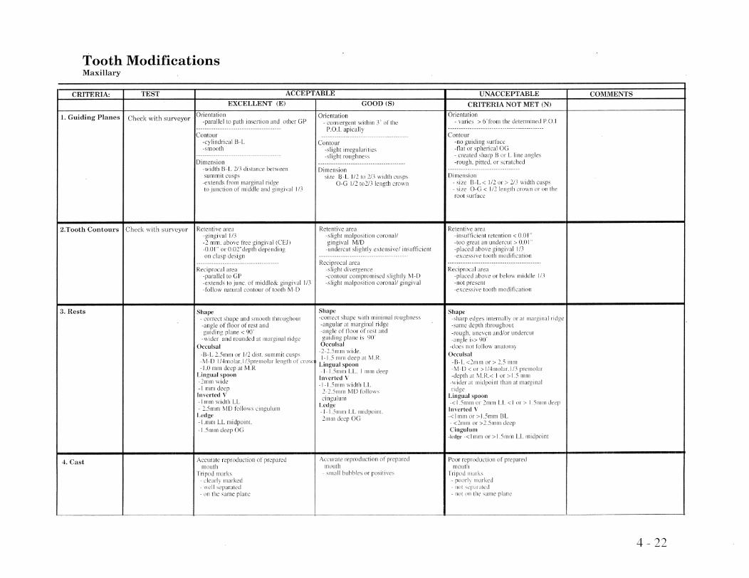
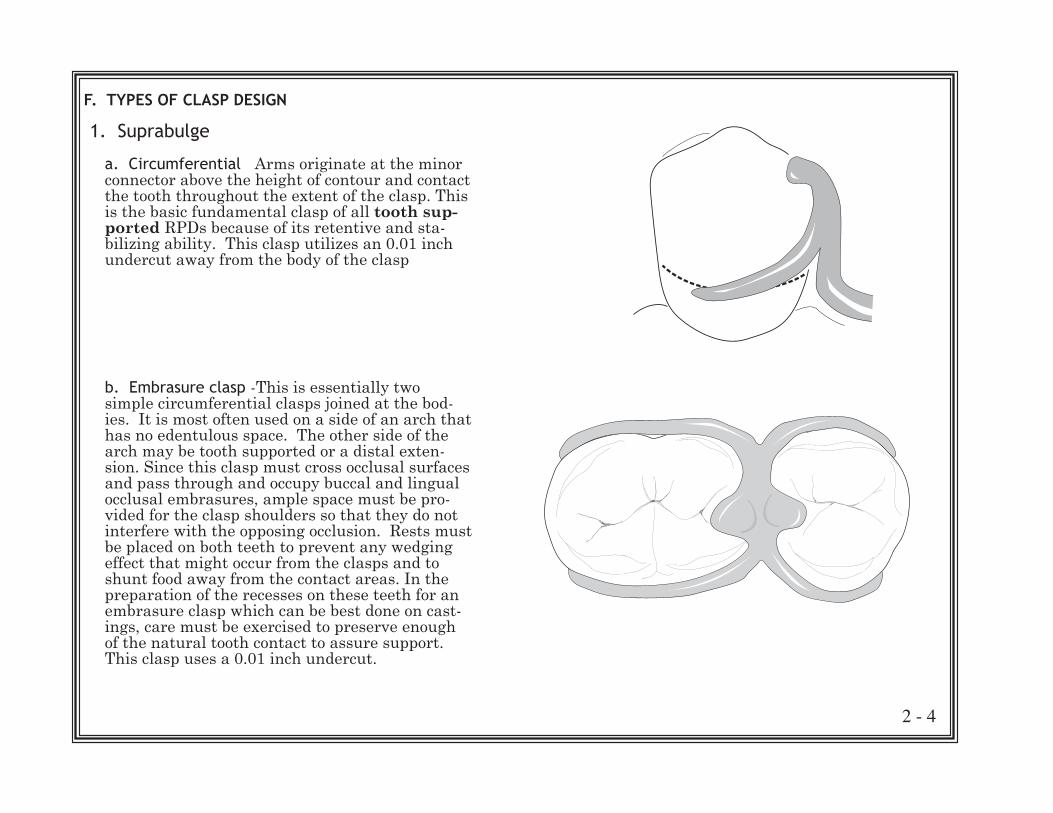
Tooth Modifications Maxillary
CRITERIA: TEST ACCEPTABLE EXCELLENT (E)
1. Guiding Planes Orientation Check with surveyor -parallel to path insertion and other OP
2.Tooth Contours Check with surveyor
3. Rests
4. Cast
Contour -cylindrical B-L -smooth
Dimension -width B-L 2/3 distance between summit cusps -extends from marginal ridge to junction of middle and gingival 1/3
Retentive area -gingival 1/3 -2 mm. above free gingival (CEJ) -0.01" or 0.02"depth depending on clasp design
Reciprocal area -parallel to OP -extends to junco of middle& gingival 1/3 -follow natural contour of tooth M-D
Shape - correct shape and smooth throughout -angle of floor of rest and guiding plane < 90 0
-wider and rounded at marginal ridge Oeeulsal
-B-L 2.5mm or 1/2 dist. summit cusps -M-D I 14molar, I 13premolar length of crow -1.0 mm deep at M.R
Lingual spoon -2mm wide -I n1l11 deep Inverted V -I mm width LL - 2.5mm MD follows cingulum Ledge -I.mm LL midpoint, -1.5mm deep 00
Accurate reproduction of prepared mouth
Tripod marks - c1earl y marked - well separated - on the same plane
GOOD (S)
Orientation - convergent within 3' of the
P.O.!. apically
Contour -slight irregularities -slight roughness
Dimension size 8-L 1/2 to 113 width cusps
0-0 1/2 to2/3 length crown
Retenti ve area -slight malposition coronall gingival MID -undercut slightly extensivel insutticient
Reciprocal area -slight divergence -contour compromised slightly M-D -slight malposition coronal/ gingival
Shape -correct shape with minimal roughness -angular at marginal ridge -angle of floor of rest and guiding plane is 90° Oewlsal -2-1.5mm wide, 1-1.5 lllm deep at M.R.
Lingual spoon -1-1.5mm LL. I mm deep Inverted V -1-1.5mm width LL
2-2.5mm MD follows cingulum
Ledge -1- t .51ll111 LL midpoint. 2mlll deep 00
Accurate reproduction of prepared mouth
- small bubbles or positives
UNACCEPTABLE
CRITERIA NOT MET (N) Orientation
- varies> 6'from the determined P.O.I
Contour -no guiding surbce -flat or spherical 00 - created sharp B or L line angles -rough. pitted, or scratched
Dimension - size B-L < 112 or> 2/3 width cusps - size 0-0 < 1/2 length crown or on the root surface
Retentive area -insufficient retention < 0.0 I" -too great an undercut> 0.0 I" -placed above gingival 113 -excessive tooth modification
Reciprocal area -placed above or below middle 1/3 -not present -excessive tooth modification
Shape -sharp edges internally or at marginal ridge -same depth throughout -rough, uneven and/or undercut -angle is> 900
-does not follow anatomy Oewlsal
-B-L <2mm or> 2.5 mm -M-D < or >1/4molaL1/3 premolar -depth at M.R.< I or >1.5 mm -wider at midpoint than at marginal ridge
Lingual spoon -< 1.5mm or 2mm LL <lor> I.Smm deep Inverted V -<I mm or >I.Smm BL - <2mm or >2.5m111 deep Cingulum
-tedge -<I nlln or >1.5mm LL midpoint
Poor reproduction of prepared moutil
Tripod marks - poorly marked - not separated - not on the same plane
COMMENTS
4 - 22

Tooth Modifications Mandibular
CRITERIA: TEST ACCEPTABLE
1. Guiding Planes
EXCELLENT (E)
Check with slllveyor Orientation -parallel t.o path insertion and other GP
Contour -cvlllldncal B-1. -S(1100t!1
Dimensi{lIl -width B·L 2/.1 dis)allce belween \urnnn[' cusps
-extends from rn,m.~i!lC:ll tn jUllcti()n uf lllidZJ1c and In
2.Tooth Contours Check with surveyor Retentive area
3. Rest.s
-£im~ival l/:i -2 n~ll. aho\\' free -0.01' [11
nil cla:-.p design
Reciprocal area -parallel to GP
(CLI)
-~xte!lds tu jUlie (11 Illicldlc& gingival l/3 -follow natural (nil/our ur tooth 1\.11-0
Oemlsal -8-L 2.:)[1]111 01 1/2 dist. :~UIlHljll ,:usps -VI-I) l/4nl(lI~11 length l)f lTOWI
-10 Illlll de,·p at
Distal Incisal -1!.1~m.lj'llllldcq)
-\vidt'l" iill£!uai than buccal -axi,d Il()o~ 8L is <911 til PUI ',l\iai wall is to -illlernal aJlglc j,":' f(llllllk'd
Shape - conte! ,;jwpc'
of flour or rc"t ~l[ld pl~!lk: < Ijii
-wider at 11l'-lr~inal -rounded ,it L
-Sl1ll1(11il
GOOD (S)
Orientation - cOl1\'ergent Within 3'- of lhe
POI. apically
C(liltour -,;light irregularities -."light roughness
I)illlellsioll size B-L In to 2/3 Width cusps
o-c 1/2 t0213 lellgth l'l\lWn
Retentive area -slight malpllsitioll coronali "in"ival MID -~mkrcut slightly (:\["'::11:-.1\('1 i!lc'uflicit'1l1
Reciprocal area -slight diven-..'cnce -co~tour cO';lpromiscd -slight malposition
M-D
Oeculsal .
-B-1. 2-1.5mm or "pplOX 1'1 dlSl. sUlllmit
-M-D approx kllglh 01 Ci'()\\n -1-1'111111 deep al ,\I.R
llistallncisal -1-1.5111l1ldecp -same \-\ idth buccal JS lillQULll -axial tlllor HL is 8S to '-
9-" 10 POI
Shape -slight change ill depth al center
-ClIl0:k of !lour ~lr re,-;t and g~!idillg r1lllll; :::: 9()'
-!tlillilllal muglJllt:ss
UNACCEPTABLE COMMENTS
CRITERIA NOT MET (N) Orientation ----+------------------j
- laries > 6 fro III the delermined P 0.1
Contour -lhllZUiding surface -tlat~)r spl;;"rlcal OG -created sbarp H or L line angl~,:.) -mugho pittE'cL or scratched -overreducl'd
Dimension - s1I.e 8-L < 112 or > ~/J width cu~p) - size O-Ci < 112 length crown (l]" IJll the root <.;urrace
Retentive ,u'ca -illSullicicnt retentiun < (J.() )"
-too great all undercut> OJ) I' -placed ubovc gillgi\-~d ) I?, -excessive [(10th lllodii'icatloll
Reciprocal area -placed abm'e or below rlllddlc -!lot present -excessive t(){Jlh !llOdificatlCln
Oeeulsal -8-1. <21ll111 or > 2':;; Illill -l\'l-D < PI' >rcljuircd length \)1' cmWll -depth at \1.1'.< I or> I 5 nlill
-\vider at midpoint lilall at nwrgilwJ ridge
DistallJl('isal -<II_,M!) ('I' >lnMD -<IJJ!ll1ll (If >2111111 deep -II Ider buccal than -aXial 11001' '\'1Il is
Shape -"l1mp edgl',":' illkrually or ull11~lr~1l1,d rld~e -same depth throughout
Clnd 1I!l1'\\~1l
-rest Ulltk'rcut -mlgle i.\> yO
----------~~--- ~-.~--.--.-.-- .. --~-- ----'-------~~---.----.--~-. ------'-------------- ---------------'----------------------------j
4 - 23

Tooth Modifications Rests
CRITERIA: ACCEPTABLE
Occlusal Rests
EXCELLENT (E)
Shape - eorreel shape and snlOolh IhroughoLiI
Ilf liullr of IN und plolle < 90
-wider and rounded almarglnal ndgc Oemlsal
-B-L 2.511l1ll or !/~. di'iL ~llJ11lllil -\I-IlI/~nl\1laL 1/_'prell1o!c,r length -J.(llliln deep al M.I<
GOOD (S)
Shape -correct ,,>hape with minil1l;li rOllghnc:)s
al
-2-1.5lllf1l \\·idc'. 1-1.5 111m delTal \LR
UNACCEPTABLE
CRITERIA NOT MET (N)
Shape -incurrec! -;.;klrp edge;.; ur at marginal Jid2t? -same' depth throl.l~llUllt '- '-
uneven and/Ill unc!elcul
lllill
COMMENTS
-+-------------1--------------+---------Embrasul'c Marginal Hidge <lnd Sluiceways
-)](1 undL'ITuh
buccal :lIld lim::ual cmbr:burcs I-I j mill [~) allu\v for C],lSp
IVIarginal Ridge and Sluieeway~
I :ll1ll1(1
-110 llildelnll,~
embrasures il1rcbsp
-undc>rculs
buccal ~ll1d lin~l1al t'fllDr:1'-;UrC:i <I III In 111- ~j.s Illlll
~-------4---------------4_-----------4_----------------_+----------Can inc Rests Lingua!
" 2Jll III -I I11Ill dLcn
Inverted \ -lm!l1 \\,idth U" - "II) (".Ieller, IU" nlill \JR -()(j al 1IIIdl1l',~:-l\f l'ill~uluIll - ((,1 ill\.\. \ l·in.~LI!ltlll
I,edge -1_1;IIIlLI -! .~illill
lli\tullnci,al
L _____________________ ----
[() POI
Lingual SpOOll
-1-1.5111111 L.L, I.~ 111111 d\:'c'jI
Inverted \" -1-1)111111 \lldlll 1.1 -\11) :-hnn ('II \11\ i}jJllIll
-OG (II thicKIlC-":" l-I]' cinglllulll -±- ! :11 III
-fullo\\.') L'iil~Lllliill
L.L m:\.i!)11111\
2111111 dCql (lCi
DiltalIn('ilui -1-i.5il1llllk\:j'
·sal11t' \\'ililil bUlL':li iillgU:-I! <l\j;Jj ill1l-)r Bl III
el5 I'll I
I.ingual SP!)()J1 -<1.5111111 or 2 III 111 LL <I.;,) > l.~miil deep
Imerted \ -<lllllll (Ir >1.5111111 Bl - Mil ,"It'lI(ls llilllU,h \IR ~ tll(J high 1)1' [(I ]\m 1.111 i.:i!'l~u!UIll
l.edgt.' -<lllllll m >1.5llilllj,] lllllirlUI!l1
->111l1ll dt'Cp U(;
Distal Indsul -< I/.\\IIJ ur > f, ;,\111 -<I.Ol1liTIIJr">2rnlll dC'll' -\\-idcr bUCi .. ::I] 111:11l
-a\i:rllloorMD is
__________________________ -.-J. _____ _
4 - 24

DRAWING THE FINAL DESIGN ON THE MASTER CAST:
Once all modifications and rest preparations are com-pleted the design is drawn on the master cast before sending it to the laboratory. In this course the distrib-uted casts, after modification, will be used as master casts. The final design is made on each cast. The use of different colored pencils aids in the delineation of various partial components and differentiation be-tween survey lines and partial components. The exact sequence to be followed in drawing the design is im-material, but a systemized routine is recommended so a neat, orderly, concise sketch can be made that is easily understood by the dental technician.
1. Resurvey: Place the master cast on the surveyor table and orient to the determined path of insertion. For the laboratory project use the tripod marks to do this. Then with the carbon marker, protected by the metal sheath,rescribe the height of contour or survey line around each of the abutment teeth. They should now be in the ideal postion for place-ment of the component parts of the clasp assembly. Remember, if the clasp components do not contact the tooth surfaces in their designated postion the clasp assembly will not function as planned!
2. Mark Undercuts: Replace the carbon marker with an undercut gauge of proper size and locate the gauge on the abutment tooth so the barrel contacts the tooth at the survey line. Move the gauge to the predetermined retentive area of the tooth and slide it up or down until the lip of the gauge contacts the tooth in the precise spot that will be contacted by the retentive portion of the tip at the same time that the barrel or gauge contacts the survey line. A small mark is made on the tooth at the exact point the lip of the gauge contacts.
5 - 1
CHAPTER 5 - DRAWING THE FINAL DESIGN ON THE MASTER CAST

3. Drawing the components:
Major connectors: General rules for defining the con-nectors:
a. The gingiva must be either completely cov-ered by a adequately relieved component of the RPD or the components must be placed at least 4mm (mandibular) or 6mm (maxillary) away from the gingival margins
b. All crossings of the gingival margin must be made at 90 degree angle
c. Try to finish the borders of the connector in low areas of the tissues rather than on a promi-nence
d. Mandibular major connectors: - Lingual bar- superior border no less than
4mm inferior to gingival margins, inferior border at the height of the alveolar lingual sulcus when the tongue is elevated.
- Linguoplate-superior border follows the cingulum of the teeth rising to the contact
points, inferior border is the same as the lingual bar
e. Maxillary major connectors: - rugae area - follow the valleys as much as
possible, when crossing rugae do so at 90 degree angles to the crests
- lateral borders - follow parallel to gingival margin at least 6mm away
- medially - parallel to the junction of vertical and horizontal parts of the palate - posterior border - straps and bars traverse
palate just anterior to vibrating line - placement of straps - place strap so it covers
area where it is in two planes giving it more rigidity
5 - 2

Minor connectors: Join the direct and indirect retain-ers to the major connector. They should be approxi-mately 2mm wide except those which are acting as proximal plates which should be two thirds the width of the summit of the cusps of the abutment tooth. They should be placed whenever possible in a interproximal space and fill the space as much as possible for patient comfort. Remember they must cross the gingival margin at 90 degrees and should not join the major connector with sharp angles. Adjacent connectors must be at least 5mm apart for oral health.
Retentive mesh: The minor connector which retains the acrylic base and artifical teeth. It should al-ways extend over the crest of the ridge to prevent fractures. Adequate bulk and strength in the metal at the junction of the grid and the major connector is necessary. The mesh should extend extend to just anterior to the retromolar pad on the mandibular and over the tuberosity on the maxillary. It should not interfere with tooth placement.
Clasp arms: using a pencil with a sharp point, draw the retentive arm red so that it passes from the rest to the retentive undercut. It should pass gracefully from supra to infra bulge as it crosses the survey line. The lower border of the clasp tip should end precisely on the mark that indicates the proper depth of undercut. The reciprocal arm is drawn, maintaining its inferior border at or above the sur-vey line. The occlusal, lingual or incisal rest is then outlined. The width of the arms at the terminal tip should be one half the width of the arm at the shoul-der.
5 - 3

5 - 4
Lastly any additional notations such as different types of teeth, areas to be relieved, areas of beading, finish lines, and any areas of notation that further clarify the design are made.
Remember that the drawing is not rough sketch; it is a precise line drawing of the partial framework plac-ing the various components exactly where intended. The quality of the work you provide the technician is directly proportional to the quality of the work you will receive in return. If the width of the clasp arms are excessively thick or thin or poorly shaped, don't be suprised if the final casting is the same; if the major connector is drawn too close to the marginal gingiva expect the same in casting; if one forgets to draw a clasp arm or rest expect the same in the casting unless you are employing a technician more astute or consci-entious than yourself.

5 - 5
1. BLACK LEAD • Contour Lines • Tripod Marks
2. RED • Retentive Clasp Arms • Finish Lines • Circle Around Tripod Mark
3. BLUE • Major Connector • Minor Connectors • Reciprocal Arms
COLOR CODE FOR DRAWING DESIGN FOR A RPD FRAMEWORK ON THE MASTER CAST


6 - 1
WORK AUTHORIZATION:
OBJECTIVE: To familiarize the student with the written procedures necessary for communication with the labo-ratory technician
PROCEDURE: The Work Authorization is a written direc-tion for laboratory procedures to be performed in the fabrication of dental restorations by a laboratory tech-nician. The purpose of this document is to provide the laboratory with clear, concise understandable instruc-tions concerning work to be done and to protect the patient from the illegal practice of dentistry.
There are legal and ethical implications concerning this matter. Presently, no federal statutes governing the operation of dental laboratories or the working agreement between the dentist and technician exist. This authority lies with the individual states. Gener-ally, these laws state that the technician cannot ser-vice any patient directly and he can legally perform only work authorized by a dentist. As a means of implementing this arrangement, most states require that the technician perform laboratory work only after he has been authorized to do so by a written order from the dentist. The written order is called a work authorization. The primary purpose is to protect the patient from illegal dentistry. The dentist has an ethi-cal obligation to protect the health of his patient by not delegating any work to a less qualified person that requires the professional expertise and competence of a dentist.
CHAPTER 6 - WORK AUTHORIZATION
The dentist has a further responsibility to closely su-pervise the work of all auxiliary personnel. The den-tist who does not honor these legal, ethical and moral commitments by assuming his full responsibilities is betraying his personal integrity. If such irresponsibil-ity becomes widespread, the general public will seek to change the laws so that certain phases of dental practice can be performed by others less trained and qualified. There are people ready to assume this role and we as dentists will have no one to blame but ourselves. The dentist is responsible for all phases of a removable partial denture service. He may request a dental technician to engage in certain mechanical phases but the technician is responsible to the dentist and never to the patient. The dentist who relegates the survey and design of a partial denture to a techni-cian is committing a grave injustice to the trust the patient has placed in him.

Content of a work authorization
Must Include: 1.) name and address of the dental laboratory 2.) name and address of the originating dentist 3.) date the case is sent 4.) date to be returned 5.) patient identification 6.) work detail 7.) signature of dentist 8.) dentist’s license number
6 - 2
Typodont No.
State University of New York at Buffalo
School of Dental Medicine – Squire Hall
REMOVABLE PROSTHODONTICSLABORATORY WORK AUTHORIZATION
To: Date:
Address:
Student: Instructor:
Patient: S.S. # :
General Request:
Date & Time Req.: Alloy for Framework:
General Instructions for RPD framework:1. Orient cast to surveyor rod using tripod marks. Use parallel blockout of undercut areas crossed by rigid parts of framework. Follow design exactly as drawn on cast.
2. Relieve the following: ❒ Gingival crevices and margins crossed by major or minor connectors ❒ Tori or prominent median palatal raphe ❒ Inferior border of mandibular major connector-26 GA wedge shaped ❒ Underretentivelatticework-26GAtoformaninternalfinishline
SpecificInstructions:
Student Dentist's Sig.
Instructor Sig. Lic. # :
UPPER
RIGHT LEFT
RIGHT LEFT LOWER

The work detail should be a clear, concise description of the work required. The technician should not be expected to wade through a poorly organized, wordy composition, nor should he be forced to make an edu-cated guess at what the dentist wants. The work detail should be in outline form and include the follow-ing topics in the case of a partial denture framework construction.
l the type of metal to be used. This could be gold or one of the various cobalt-chromium alloys. One would also explain the use of a wrought clasp here, specifying its shape, makeup and gauge.
l Major connector, type, food dam bead if necessary.
l Abutment tooth list the specific tooth (abbreviation is ok, eg. 1st premolar) and the number to identify it.
Then list: 1. Rests - the type of rest and where on the tooth it is located, e.g. spoon rest on mesial occlusal sur- face. 2. Retention - type of clasp and the retentive area, e.g., mesial buccal undercut. 3. Reciprocution - type and location, e.g., cast arm on the lingual surface.
l special instructions, this will vary with the indi-vidual case and may include such things as type of retention latticework to use, the placement of special types of replacement teeth, the mode of tripoding used, special waxing specifications, special finishing proce-dures.
The work detail, along with the drawing of the design on the cast, should relate to the laboratory techni-cian everything he must know for the individual case in order to fabricate it properly. Tasks that must be performed on all cases and common to all cases such as duplication of models, polishing, etc. need not be included on the work detail.
6 - 3

Relationship between Dentist and Technician
Dentist's Responsibility
The dentist must plan the prosthesis in its entirety. He must plan for all preparatory mouth treatment and then proceed to do it. Sufficient space must be avail-able for each structural element, abutment teeth must be properly prepared and contoured to receive guide planes, rests and clasp arms. The dentist must also prescribe all materials to be used. He must be respon-sible for impressions, jaw records, fitting the frame-work in the mouth and final insertion of the finished case. He is also responsible for patient instruction in its care and post insertion adjustments and mainte-nance
Technician's Responsibility
The technician is responsible for fabrication of the prosthesis with the materials prescribed in accordance with the directions received on the work authorization form.
The importance of establishing a good working rela-tionship between the dentist and technician cannot be overemphasized. It is based on a common understand-ing of the overall objectives, an awareness of each person’s role and an appreciation of the problems that each person might encounter. Within this framework, legal and ethical considerations can be established along with the basis for sound business management. The purpose of all this is to best utilize the expertise of two trained people to deliver to a patient the maxi-mum in health care in the most efficient manner. To do this so it is profitable to all; patient, technician and dentist, the dentist must be the one to assume the ini-tiative, ultimate leadership and delegation of responsi-bilities.
6 - 4

USE OF CAST RESTORATIONS ON ABUTMENT TEETH:
OBJECTIVE: To improve the contours of the abutment tooth to further compliment the determined design of the RPD
PRINCIPLES:
ADVANTAGES:1. Heavily restored tooth can be strengthened 2. Multiple cavosurface margins reduced to single finish line3.Disadvantageous morphology may be improved
DISADVANTAGES:1. Increased cost2. Increased complexity of the procedures both clinical and technical
Never should you design a cast restoration in a semi edentulous situation before first determining the design of any RPD that may be necessary even if the RPD is not being fabricated at that time. The same holds true about fabricating a RPD before evaluating the abutments for cast restorations and completing the ones indicated.
PROCEDURES:
1. Survey the study cast and design the RPD 2. Determine the type of any restorations needed 3. Make all tooth modifications necessary not involving the teeth indicated for castings 4. Prepare the abutment tooth 5. Make a complete arch working cast with neces- sary die or dies 6. Fabricate a surveyed restoration 7. Try in the restoration 8. Complete arch impression with the casting in place 9. Survey resulting master cast and write up work authorization 10. Send to laboratory for fabrication of framework 11. Try in framework with the castings 12. Castings usually are cemented when the com pleted RPD is inserted
7 - 1
CHAPTER 7 - USE OF CAST RESTORATIONS ON ABUTMENT TEETH

8 - 1
CUSTOM MATRIX:
OBJECTIVE: To provide a easy method of relating the pos-tion of teeth to the residual ridge for purpose of locat-ing portions of the framework particularly retentive loops or posts.
INSTRUMENTATION REQUIRED:
• Cast• Dentureteeth• #7Waxspatula• Bunsenburner• Baseplatewax• Hollenbeckcarver• Alcoholtorch• Handpieceandburs
PROCEDURES:
1) Place a groove in the lingual of each tooth to receive the retentive post
CHAPTER 8 - CUSTOM MATRIX

2)Settheanteriorteethandwaxtofullcontour
8 - 2

3)Alcotetheadjacentteethandplacethebeadingwax
4)Pourstonematrix
8 - 3
10-4
10-5
10-2
10-9
10-3, 10-6
10-4
10-5
10-2
10-9
10-3, 10-6

5) Boil out the baseplate wax and lute the teethback to the matrix with sticky wax
6) Fit the matrix back to the cast
8 - 4

7) Locate the retentive wax posts in the grooves on the lingual of the teeth
8 - 5
8) Finished framework on cast showing retentiveposts

PLACEMENT OF BLOCKOUT AND RELIEF WAX:
OBJECTIVE: To acquaint the student with the principles of blockout and relief and to familiarize him/her with the parts of the procedure that are the responsibility of the dentist
INSTRUMENTATION REQUIRED:
• Castneedingblockout• NeyBlockoutwaxorreliefwax• #7Waxspatula• Surveyorwithwaxknife• Bunsenburner• Hollenbeckcarver• Alcoholtorch
Somecasesduetotheircomplexitymayrequirethepractioner to do the initial block out on the master cast. For these cases, in addition to an accurate draw-ingthemastercastshouldalsohavelaboratoryplaceblockoutwaxontheguidingplanestotheintendedwidthofthefinishedguidingplate.Thiswillmakeiteasier for the technician to orient the cast and protect fromhavingthetechnicianoverrelievetheguidingplanes.Wealsorecommendtheclinicianplacereliefwherearmscrossgingivalmargins,andanyotherar-easrequiringspecialconsideration.Thelaboratorycanthen place routine block out and relief on the remain-der of the cast.
9 - 1
CHAPTER 9 - PLACEMENT OF BLOCKOUT AND RELIEF WAX

TECHNIQUE:
Whenusingaparallelblockoutwaxtechnique,con-siderablecaremustbeexercisedinplacingthewax.Ifthewaxisnottrimmedsufficientlytoexposeguideplanesafterapplyingitwithahotspatula,thenthecastingwillberelievedawayfromthetoothandwillnot contact the tooth and so we lose the function of thatguideplane.Iftoomuchwaxisplacedornottrimmedsufficientlyafterithasbeenplacedinadeepinterproximalspacebeneathaminorconnectororlinguoplate,thenthispartofthecastingwillhaveneedlessspacebetweenitandthetoothandserveasan unnecessary food trap. If on the other hand, we areoverzealousintrimmingbackthewax,itiseasyto scuff or abrade the stone tooth surface. This would leadtoacastingthatfitsthemodelbutwouldstrikeprematurelyinthemouthandnotgotoplace.
Inapplyingtheblockoutwax,theNeyhighfusingundercutwaxsuppliedinthestudentkitshouldbeused.Ahighfusingwaxsuchasthis(actuallyawax-claymixture)isnecessarytowithstanddistortionfromtheheatoftheduplicatingmaterialwhichispouredatabout120˚.Theblockoutwaxisappliedtotheteethwitha#7waxspatulaorlargeP.K.Thomaswaxinginstrument.Thespatulamustbehotenoughtocausethemeltedwaxtosatisfactorilysticktothetoothoritwillbepulledoffwhenanattemptismadetocarveitwiththesurveyorblade.Atthesametimethewaxshould not be so hot to be drawn into unwanted areas bycapillaryattraction.Thestudentshouldexperi-mentonafewtrialteethbeforeattemptinganythingonhisworkingcasttogetthefeelofhandlingthismaterial.
9 - 2

Afterthewaxisapplied,itistrimmedfirstgrosslywithhandinstrumentssuchasaCutlercarverorHol-lenbeckcarverandthenwiththesurveyorbladetrim-mer.Trimmingcanbefacilitatedbyslightlywarmingthe blade with an alcohol torch.
9 - 3

10 - 1
ASSESSING A PARTIAL DENTURE FRAMEWORK:
OBJECTIVE: Although the typical dentist today in his practice neither fabricates a wax-up for a partial den-ture framework nor constructs a partial casting, it is important that he/she is able to assess a framework for clinical acceptability. He/she does this for a number of reasons;
•togainanunderstandingofthework delegated to a dental technician •toseethecontoursandthicknessesneeded in a properly constructed casting •toenablethestudent/dentisttoevaluatethe finishedcastingreceivedfromthetechnicianto maintain quality control
PROCEDURE:
Pre-insertionevaluationonthecast On the cast •design •placement Off the cast •fit-conditionofmastercast •finish Intra-oralIntrasealevaluation •fit •retention •occlusion
Pre-insertion EvaluationFramework on the cast
CHAPTER 10 - ASSESSING A PARTIAL DENTURE FRAMEWORK

10 - 2
Major Connectors:
Threemaincriteriamustbeevaluated:
•design •shapeandsize •position
1. Design.Thedesignmustfollowtheonespecifiedbythelaboratoryworkauthorization.Thetechnicianmay not change this without consulting and prescrib-ingdentistfirst.
2. Shape and size. Thickness is important because, it along with the design, is necessary to gain the needed rigidity that is absolutely crucial to insure the effec-tivenessofthemajorconnectorandultimatelythepartial denture.
3. Position.Inlocatingthemajorconnector,onemusteithersupporttheconnectorwithrestsandrelievethegingivaitcontactsandapproachesorlocatetheconnectorfarenoughawayfromthegingivaltoavoidimpingement. On the maxilla this distance is usually 6 mm., on the mandible the distance is usually 4 mm.
Mandibular Major Connectors
A mandibular lingual bar connector should be half-pear shaped with the thickest part placed inferiorly. Itshouldbenonarrowerthan4mmincisal-gingivallyand 1/2 the thickness of a #6 gauge sprue inferiorly. Placementisasclosetothereflectionofthefloorofthemouth as possible inferiorly and at least 4 mm from thegingivalmarginsuperiorly.
A mandibular linguoplate is used when there is insuf-ficientroomforthelingualbar.Itisthesamesizeandshapeinferiorlyasthebarbutitextendsoverthelingualsurfaceoftheteethtocoverthecontactpointand cingulum superiority.

Maxillary Major Connectors
Themaxillarymajorconnectorsareforthemostpartmade with a double thickness of 26 gauge sheet wax cut out to the desired contour and width or anatomic replicapatternequivalenttoa22gaugewaxsheetwhich is a duplication of the palatal portion of a max-illary cast. The anatomic replica pattern is usually preferred because patients become accustomed to the anatomic replica palate much more readily than to a smooth highly polished or to the concentrated bulk of palatal bars. The irregular surface also seems to be an aid in mastication because the tongue can separate softer foods more easily. Anatomic replica patterns can be slightly thinner than standard because their ir-regularshapegivesmorerigidity.Inapplyingthepat-tern to the maxillary cast no matter what form is used, an attempt should always be made to place the form intwodifferentplanesbecausethiswillgivethemajorconnector more rigidity for the same amount of bulk. Amajorconnectorinvolving2planesgivesmuchmorerigidity than same width connector in 1 plane. In a combinationanterior-posteriorbarmajorconnectortheanterior bar is made with a double thickness 26 gauge waxsheetoranatomicreplicapatternequivalenttoa22 gauge wax sheet and the posterior bar is made with a half round 6 gauge wax. Because the posterior bar is relativelynarrow,thehalfround6gaugewaxshapeisused rather than the wax sheet to gain the rigidity.
10 - 3

Minor Connectors:
•size •location •shape
Aminorconnectorthatwillmakeupthebodyoftheclaspisthesizeofa#6or#8gaugewaxsprue.Heretheminorconnectormustbewideenoughtouti-lizetheguidingplanetoitsfullestadvantage.Whereitgivesrisetoaclasparm,itshouldbetaperedtothetoothbelowtheoriginoftheclasp.Thejunctionoftheminorconnectorandclaspshouldhaveroundedangles.Ifnoclasparmispresentsuchaswhenabarclasporiginateselsewhere,itshouldbetaperedtoaknifeedgethefulllengthofitsbuccalaspect.
Whenanartificialtoothwillbeplacedagainstaproximalminorconnector,thebuccalandocclusalaspectisthinnedtoaminimumandthegreaterbulkisplacedtothelingual.Thisistoenablethebuccalplacementoftheartificialtoothasclosetothenaturaltoothaspossibleforestheticsandstillinsureenoughbulkforrigidityoftheminorconnector.
10 - 4

Aminorconnectorcontactingtheaxialsurfaceofanabutmentshouldneverbelocatedonaconvexsurfacebutinsteadinanembrasurewhereitwillbeleastnoticeabletothetongue.Itmaybeformedusinga10gaugeroundwaxshapeandshouldconformtotheinterdentalembrasure,passfromthemajorconnec-tortotheothercomponents.Aninterproximalminorconnectorsuchasthatsupportingarestforanindirectretaineriswedgeshaped,thickestatitslingualsur-faceandtaperedintotheembrasure.Anyundercutintheembrasurewouldhavebeenblockedoutwithparallelblockoutpriortoduplication.Wherethemi-norconnectorcrossesthegingiva,reliefshouldhavebeenplacedonthemarginalgingivapriortoblockoutaswell.Minorconnectoremergesfrommajorconnec-toratarightangle,sothatthegingivacrossingisasabruptaspossibleandaminimumofmarginalgingivaiscovered.Thejunctionoftheminorandmajorcon-nectorsshouldberoundedandfreeflowingtopreventtongueirritation,foodentrapmentandstructuralweaknessinthemetal.
10 - 5

Minor Connector
Ideal
Common Errors
Joinsmajorconnectorwithsharpangles
Doesnotjoinmajorconnectorat90˚angle
10 - 6

10 - 7
Rests: The general shape of the rest is concave, never convex and in the general form of the occlusal surface before the rest preparations were made. Sufficient bulk must exist at the marginal ridge area.
Retentive Clasp Arms
Circumferential Clasp
• relation to survey - The clasp arms must be placed with on the terminal 1/3 in the undercut. The tip of the inferior border of the terminal 1/3 is placed at the desired area of undercut.
• size and taper - Retentive clasp arms can be formed using 12 gauge half round wax shapes but pre-formed plastic patterns are recom mended because the desired taper of the clasp is already established. The taper is necessary because it contributes to the flexibility of the clasp as it must engage the undercut area of the abutment tooth. It is most important that the clasp arm be joined to the minor connector with smooth rounded angles or internal stresses will be present in the metal as the clasp flexes.
Bar clasp
• relationtosurvey-The arm engages the under cut only at its terminus.
• size and taper - The approach arm of the clasp should have a taper from the point it emerges out of the resin base to the tooth contact. A finish line can be formed at the point the approach arm and resin meet.

Joins major connector at sharp angles
No taper
Uneven arc to clasp
10 - 8
RETENTIVE CLASP ARMS
Ideal
Errors

Reciprocal Clasp Arms
• relation to survey - The entire clasp arm is at or above the height of contour. The ideal position is middle 1/3 of the tooth
• size and taper - Reciprocal clasp arms can be formed by free hand waxing or the use of pre- formed plastic patterns or ready made wax shapes. 12 gauge half round wax or one of the many shapes of the pre-formed plastic patterns is simply laid on the tooth surface and smoothly blended into the minor connector. Since reciprocal arms are not placed into undercuts, there is no need to taper them except to contour them so they are non-irritating to the tongue. The junction of the minor connector and reciprocal clasp arm is rounded.
10 - 9

10 - 10
RECIPROCAL CLASP ARMS
Ideal
Errors
Joins minor connector with sharp angles
Too thin
Placed too high on tooth

Retention Latticework: Proper position:
At the conclusion of the final laboratory session, the student must submit to their instructor one cast that has a completed partial denture wax-up on it.
11 - 11
Finish lines: Sharp, definite, butt-type finish lines are incorporated into the metal because it is here that the acrylic resin meets the metal. An angle no greater than 90° will ensure a neat junction of the two materials and will preclude the formation of a thin feather edge of resin overlapping the metal which is unsightly, unhygienic and prone to fracture. A comon error, however, is to place too deep a finish line at the junction of the major connector and the latticework. This causes a thinning of the metal at a point that is vulnerable to breakage in surface.
External finish lines (oral side) should be formed in the wax pattern in a way that provides ample thickness of both metal and resin.
Internal finish lines (tissue side) are also formed by the edge of the saddle relief wax which is placed on the master cast prior to duplication.

Framework off the cast
Condition of the cast 1. Check for any areas of breakage even if they have been repaired; the possibility of distortion is very real. 2. Check for areas of abrasion. These will indicate areas of interference in the mouth.
Examine the framework
1. For porosity - which will indicate areas of weakness and probable fracture 2. For blebs or bubbles - that will prevent the framework from seating if they are in the area of hard tissues or irritation if they are in the area of soft tissue contact. 3. For polish and finish - the framework should be smooth with no scratches. 4. For nicks - check the clasp arms for nicks or weak spots.
11 - 12

LABORATORY STEPS IN FABRICATING A RPD FRAMEWORK:
In the making of an actual partial denture casting, certain steps that will not be done in our labora-tory exercises must be understood. The master cast with the final survey, blocked out of guiding planes and critical areas, drawn design and proper work authorization is sent to the laboratory for the casting to be made. The laboratory technician receives, the cast, reproduces the survey and pro-ceeds to place blockout and relief wax on all areas indicated. The master cast with the wax applied is placed in a flask and a duplicating material (revers-ible hydro- colloid) is poured into the flask. After it hardens, the master cast is removed and the negative is poured with a refractory cast material. This material is similar to the investment used for castings in other technique courses. The refractory cast which may be a gypsum investment for gold or a phosphate bonded investment for higher fusing metals is used for the actual wax-up of the partial denture framework. The wax-up must be done on the refractory cast because unlike other wax pat-terns that may be lifted off the die for investment purposes, the partial denture frame is too complex for this. So the wax-up is done on a cast that is investment material. After the wax-up is completed, it and the refractory cast is then invested in toto using a large enough casting ring to house the cast and wax-up. Wax burnout and the casting are then made in the stan-dard manner and the casting is retrieved, finished, polished and returned to the original master cast to be sent back to the dentist for try-in, in the mouth.
Preparation of the Master Cast by the Laboratory for Duplication
Block out of the master cast:After establishing the path of insertion and locat-ing undercut areas on the master cast, any under-cut area that will be crossed by rigid parts of the framework need to be blocked out by the addition of wax prior to the duplication procedure. Since all parts of a RPD are rigid except retentive clasp arms, this means that all other parts of the RPD that cross teeth and tissue that are undercut must be blocked out if the interference has not been pre-viously removed. Rigid portions of the framework cannot be constructed in undercut areas because then the partial will not go into place. Blockout on the master cast removes the interference of the undercut in question. When the master cast is duplicated and poured into a refractory cast, the blockout is duplicated as well. Therefore, the refractory cast has no undercuts other than those areas not involved in the framework or dealing with the retentive clasp arm. The wax-up of the RPD then can be freely done on the refractory cast without fear of waxing into an undercut. This type of blockout is called parallel blockout because it parallels all of the surfaces involved. Blockout wax is applied to the cast undercuts at the given path of insertion and trimmed so that it contacts the diagnostic rod or blade trimmer at the same time that the rod or blade contacts the height of contour.
11 - 1
CHAPTER 11 - LABORATORY STEPS IN FABRICATING A RPD FRAMEWORK

In essence, this converts teeth and their undercut areas into parallel cylinders. When this is done, the remaining undercuts or interferences have been circumvented and the partial framework will slide easily to place. The amount of blockout wax used to eliminate an undercut area should be minimal. If the undercut area is large, blocking it out with wax will enable one to make a casting that will go to place, but the undercut may be so large that it creates an unfavorable food trap. The excessive undercut should have been modified in the tooth preparation stage by disking, placement of a restoration or selecting an alternate tilt of the cast, if not to eliminate the undercut then to re-duce its magnitude decreasing its food entrapment potential while increasing patient acceptance.Proximal tooth surfaces that are to be used as guide planes and areas beneath all minor connec-tors receive parallel blockout. The wax is applied to the undercut area remaining gingival to the con-tact of the diagnostic rod or blade trimmer. Par-allel blockout is also used in deep interproximal spaces that are to be crossed by a minor connector or a linguoplte.
Arbitrary blockout:Refers to areas that are not involved in the casting but are blocked out for convenience. This is done to avoid difficulties in duplication of the master cast. The duplicating material is reversible hydro-colloid, and while this is highly elastic it can tear if drawn over a severe undercut. To prevent this tearing and to make ti easier to draw the master cast from the duplicating get, gross undercuts that are not involved with the framework are arbitrari-ly blocked out. This blockout can be accomplished with the use of hard base plate wax. The special undercut wax need not be used.
Relief of the Master Cast:This is done for the purpose of providing a space between the partial denture framework and the tissue. A selected thickness of wax is applied to the master cast, the cast is duplicated into a refractory model and the wax-up is done on the duplication of the wax relief on the refractory cast. When the casting is made and returned to the master cast or mouth, it does not contact the tissue in the areas that were relieved.
Areas that require relief include:
1. Gingival crevices and margins that will be crossed by minor connectors or linguoplate. Relief is necessary in these areas to prevent im-pingement of this delicate tissue so as to avoid and periodontal disturbance. The undercut wax or hard baseplate wax is flowed into these areas with a minimum thickness.
2. Areas in which major connectors will contact thin mucosa such as that over maxillary and mandibular tori and a prominent median pala-tal raphe. The thickness of wax applied is di-rectly proportional to the amount of displacibil-ity of the tissue covering the residual ridge. The more displaceable the ridge tissue, the more relief needed to cover the torus or suture line. This obviously deals with distal extension bases. In a tooth supported case, the need for relief in these areas is not as critical.
3. Beneath a lingual bar in a distal extension case if the rotation point is more to the anterior or the lingual alveolar mucosa is undercut.
11 - 2

11 -3
The relief wax is 26 gauge sheet wax and it is ap-plied in the area of the lingual bar. The superior portion is feathered and blended into the tissue, below the height of the contact of the superior edge of the lingual bar so that the top of the lingual bar will contact the tissue where possible. This is necessary to prevent food impaction, and the superior edge does not need relief because it does not move toward the tissue when in func-tion. The inferior edge of the relief wax is extend-ed all the way to the tissue reflection and kept at its full thickness. It is extended the full length to the lingual sulcular depth so to not limit the position of the inferior portion of the lingual bar.If the rotation is farther posterior, the arc of rotation of the lingual bar changes to more of an upward movement and so does not impinge the tissue. If the lingual alveolar mucosa in the area of the lingual bar is undercut, then the undercut must have parallel blockout so the framework will seat without tissue irritation. In addition the area also needs relief because of the upward rota-tion that will impinge the tissue.
4. The area under the retention latticework needs relief for the attachment of the resin base. One thickness of 26 gauge wax is applied to the ridge beyond the involved area so to not limit the placement of the latticework. The relief wax ends abruptly at a right angle at the finish line to create the internal finish line.
General Principles of Waxing
• Always be sure all parts of the wax-up are firmly secured to the model. • Avoid sharp angles in the wax-up, except for finish lines. • All junctions should be smoothly rounded. • Finish lines should be definite, sharp line angles so resin can be finished to a butt joint. • Always be sure of enough bulk in major con-nectors to insure rigidity. • Occlusal rests should be within the confines of the occlusal rest preparations and never convex in shape. • Retention arms should have a uniform taper. • All excess wax independent of the wax-up proper should be carefully removed from the model. • Slight imperfections, nicks, pits, cracks, etc. are corrected by the careful addition of wax and gentle carving and reshaping. Never attempt to flame out an imperfection.