Embed Size (px)
Citation preview

#2008 American Society of Heating, Refrigerating and Air-Conditioning Engineers, Inc.1791 Tullie Circle, NEAtlanta, GA 30329www.ashrae.org
Elsevier Science is an imprint of Elsevier30 Corporate Drive, Suite 400Burlington, MA 01803, USA
All rights reserved.
ISBN 978-0-08-055233-0
Printed in the United States of America.
ASHRAE has compiled this publication with care, but ASHRAE has not investigated, andASHRAE expressly disclaims any duty to investigate, any product, service, process, procedure,design, or the like that may be described herein. The appearance of any technical data or editorialmaterial in this publication does not constitute endorsement, warranty, or guaranty by ASHRAEof any product, service, process, procedure, design, or the like. ASHRAE does not warrant that theinformation in the publication is free of errors, and ASHRAE does not necessarily agree with anystatement or opinion in this publication. The entire risk of the use of any information in thispublication is assumed by the user.
No part of this book may be reproduced without permission in writing from ASHRAE, exceptby a reviewer who may quote brief passages or reproduce illustrations in a review withappropriate credit; nor may any part of this book be reproduced, stored in a retrieval system,or transmitted in any way or by any means—electronic, photocopying, recording, orother—without permission in writing from ASHRAE.
Library of Congress Cataloging-in-Publication DataApplication submitted
Working together to grow libraries in developing countries
www.elsevier.com | www.bookaid.org | www.sabre.org
Foreword
Welcome to the ASHRAE Learning Institute’s Fundamentals of HVAC&ReLearning System Series.This is a Course Reader to accompany the Fundamentals of HVAC Control
Systems online modules. To help you learn at the convenience, this CourseReader is also available to you as an eBook with the online Course Modules.The Course Reader will provide you with background information to help
you develop in-depth knowledge of the Fundamentals of HVAC Control Sys-tems, to improve your skills in HVAC&R and to earn the 47PDHs/4.7CEU’sawarded for successful completion of the Fundamentals of HVAC ControlSystems Learning course.We look forward to working with you and helping you achieve maximum
results from this course.

Chapter 1
Introduction to HVAC ControlSystems
Contents of Chapter 1
Study Objectives of Chapter 11.1 Why Do We Need Controls?
1.2 A Brief History of Controls 1.3 Control Loops 1.4 Control Modes 1.5 Gains and Loop Tuning 1.6 Control Actions and Normal Position 1.7 Control Range, and Sequencing 1.8 Controls Documentation, Maintenance, and Operations The Next StepBibliographyStudy Objectives of Chapter 1
Chapter 1 introduces basic control concepts. It begins with a discussion ofwhy controls are required in HVAC systems and a brief history of the devel-opment of control products. Next, we introduce the concept of a control loop,the basic building block of all control systems, and the various control strate-gies and algorithms used in control loops. After studying this chapter, youshould understand:Why controls are necessary in HVAC systems.
The difference between open and closed control loops.How two-position, floating, and modulating control loops work.Proportional control.Integral and derivative control action in modulating control loops.How to tune control loops.The difference between direct acting and reverse acting.Difference between normally open and normally closed.How controlled devices may be sequenced using a single controller.
2 Fundamentals of HVAC Control Systems
1.1 Why Do We Need Controls?
We need controls and control systems because, in our modern age of technol-ogy, they make our lives more convenient, comfortable, efficient, and effec-tive. A control enables equipment to operate effectively and sometimesgives the ability to change their actions as time goes on and conditions oroccupancies change. Controls can be devices used to monitor the inputs andregulate the output of systems and equipment. You use controls every day.For example, when you shower in the morning you sense the water tempera-ture and manually modulate the hot and cold water valves to produce thedesired temperature. When you drive to work, you monitor your speed usingthe speedometer and manually control the accelerator of your car to maintainthe desired speed. When you get to your office, you sense a shortage of lightso you manually switch on the overhead lighting.
These are all examples of closed-loop manual controls. The term manualmeans that you (a person, rather than a device) are acting as the controller;you are making the decisions about what control actions to take. The termclosed-loop means that you have feedback from the actions you have taken.In these examples, the feedback comes from your senses of touch and sight:as you open the hot water valve in your shower, you can sense the tempera-ture of the water increase; when you depress the accelerator, you can see thatyour speed is increasing by viewing the speedometer; and when you turn onthe light, you can see that the brightness in the space has increased.
Your car may also be equipped with cruise control, to automatically main-tain speed on a clear road, which is an example of an automatic control. Anautomatic control is simply a device that imitates the actions you would takeduring manual control. In this case, when you press the set-button on thecruise control panel, you are telling the controller the speed you desire, orthe set point. The controller measures your speed and adjusts the position ofthe accelerator to attempt to maintain the car’s speed at set point – the desiredspeed – just as you do when you manually control the speed.
You may notice that your cruise control system is able to maintain yourcar’s speed at a given set point more precisely than you can manually. Thisis generally because you are not paying strict attention to controlling yourspeed; you must also steer, watch for traffic and perform all of the other func-tions required for safe driving. This is one reason why we use automatic con-trols: we do not have the time or desire, or perhaps the ability, to constantlymonitor a process to maintain the desired result.
Controls of heating, ventilating and air-conditioning, and refrigerating(HVAC&R) systems are analogous in many ways to the controls we use todrive our cars. Just as we use speed as an indicator of safe driving, we gener-ally use dry bulb temperature (the temperature that a common thermometermeasures) as an indicator of comfortable thermal conditions. Just as speed isnot the only factor that affects driving safety, temperature is not the only fac-tor that affects our perception of thermal comfort. But like speed is the majorfactor in driving, temperature is the major factor in comfort and is readilymeasured and controlled. Your car’s engine was designed to bring the carup to speed quickly, to drive it up a hill, or to carry a heavy load. But becausewe do not need this peak power output all of the time, we need a control
3Introduction to HVAC Control Systems
device (the accelerator) that can regulate the engine’s power output. The samecan be said of HVAC systems. They are generally designed to handle peakcooling or heating loads that seldom, if ever, take place, so we must providecontrols that can regulate the system’s output to meet the actual cooling orheating load at a given time.We use automatic controls for HVAC systems in place of manual controls,
just as we might use cruise control to control the speed of our car. Automaticcontrols eliminate the need for constant human monitoring of a process, and,therefore, they reduce labor costs and provide more consistent, and oftenimproved, performance.The ultimate aim of every HVAC system and its controls is to provide a
comfortable environment suitable for the process that is occurring in the facil-ity. In most cases, the HVAC system’s purpose is to provide thermal comfortfor a building’s occupants to create a more productive atmosphere (such as inan office) or to make a space more inviting to customers (such as in a retailstore). The process may also be manufacturing with special requirements toensure a quality product, or it may be a laboratory or hospital operating suitewhere, in addition to precise temperature and humidity control, the HVACsystem must maintain room pressures at precise relationships relative to otherrooms. With all of these systems, the HVAC system and its controls must reg-ulate the movement of air and water, and the staging of heating, cooling, andhumidification sources to regulate the environment.Another capability that is expected of modern control systems is energy
management. This means that while the control systems are providingthe essential HVAC functions, they should do so in the most energy efficientmanner possible.Safety is another important function of automatic controls. Safety controls
are those designed to protect the health and welfare of people in or aroundHVAC equipment, or in the spaces they serve, and to prevent inadvertentdamage to the HVAC equipment itself. Examples of some safety control func-tions are: limits on high and low temperatures (overheating, freezing); limitson high and low pressures; freezestats; over current protection (e.g. fuses);and fire and smoke detection.
1.2 A Brief History of Controls
The first efforts at automatic control were to regulate space-heating systems.The bimetallic strip was the first device used; it controlled boiler output byopening and closing the boiler door, or a combustion air damper to controlthe rate of combustion. These devices were known as regulators. Other appli-cations were to control steam radiators and steam heating coils. (Most steamradiators at that time were turned on and off by hand.)Dr. Andrew Ure was probably the first person to call his regulator a thermo-
stat and we still use this name 150 years later. These devices were soon used tocontrol temperatures in incubators, railway cars, theaters, and restaurants.Two other devices were developed to compete with the bimetallic strip. The
first was a mercury thermometer column, having a contact low in the mercuryand one or more contacts above the top of the column. Increasing temperature
4 Fundamentals of HVAC Control Systems
caused the mercury to rise and make contact with an upper electrode, therebycompleting the circuit. This extremely accurate thermostat was non-adjustable.
The second device, a mercury switch uses a drop of mercury in a small,sealed glass tube with contacts at one or both ends. The horizontal glass tubeis concave upwards, must be mounted level, and will make or break a circuitwith a slight impulse from a bellows or bimetal sensor. This slight impulse ismultiplied by the mass of the moving mercury. This device (discussed inChapter 4) still is used to control countless HVAC systems.
Refrigeration systems used thermostats to cycle the motor driving the com-pressor, or to open and close valves, to modulate capacity. The first refrigera-tion systems controlled the flow of refrigerant by hand. When smallerautomatic equipment was developed, high side floats, low side floats and con-stant pressure valves (automatic expansion valves) came into use.
These early control devices were generally electric; their function was tomake or break an electric circuit that turned on a fan or pump, opened a valveor damper, etc. Some early controls (particularly burner controls on furnacesand boilers) were self-powered; meaning they drew their energy from the pro-cess itself rather than from an external source such as electricity. The need forinexpensive modulating controls (controls that could regulate output over acontinuous range rather than cycling from full-on to full-off) lead to the devel-opment of pneumatic controls that use compressed air as the control powerrather than electricity.
Pneumatic controls are inherently analog (modulating). With the invention ofthe electron tube, analog electronic controls were developed. These controlsnowuse analog solid-state (semiconductor) devices toprovide thedesired controlfunctions. Finally, with the emergence of powerful and inexpensivemicroproces-sors, digital controls were developed. Digital controls (often called direct digitalcontrols or DDC) use software programmed into circuits to effect control logic.
These five control systemtypes—self-poweredcontrols (described inChapter 6),electric controls (Chapter 7), pneumatic controls (Chapter 8), analog electroniccontrols (Chapter 9), and digital controls (Chapter 10)—are the basis of mod-ern control systems. Most control systems today use a combination of the fivesystem types and are more accurately called hybrid control systems.
All of the various types of hardware used in temperature control systems(in the past, currently, and in the future) are based on the same fundamentalprinciples of control. While the technology used to implement these principlesmay change, the fundamental concepts generally remain the same. Theseprinciples are the subject of the rest of this chapter.
(The historical information in this section is from the ASHRAE publication,Heat and Cold: Mastering the Great Indoors.)
1.3 Control Loops
The process of driving your car at a given speed is an example of a controlloop. You use your speedometer to measure your car’s speed. If you are belowthe desired speed, you press the accelerator and observe the response. If youcontinue below the desired speed, press the accelerator some more. As youapproach the desired speed, you start to release the accelerator so that youdo not overshoot it.
−
+
ControllerControlled
DeviceProcess
Plant ToControlledVariable
SensingElement
(Feedback)
Input Signal
(set point)
Figure 1-1 Diagram of Control Loop
5Introduction to HVAC Control Systems
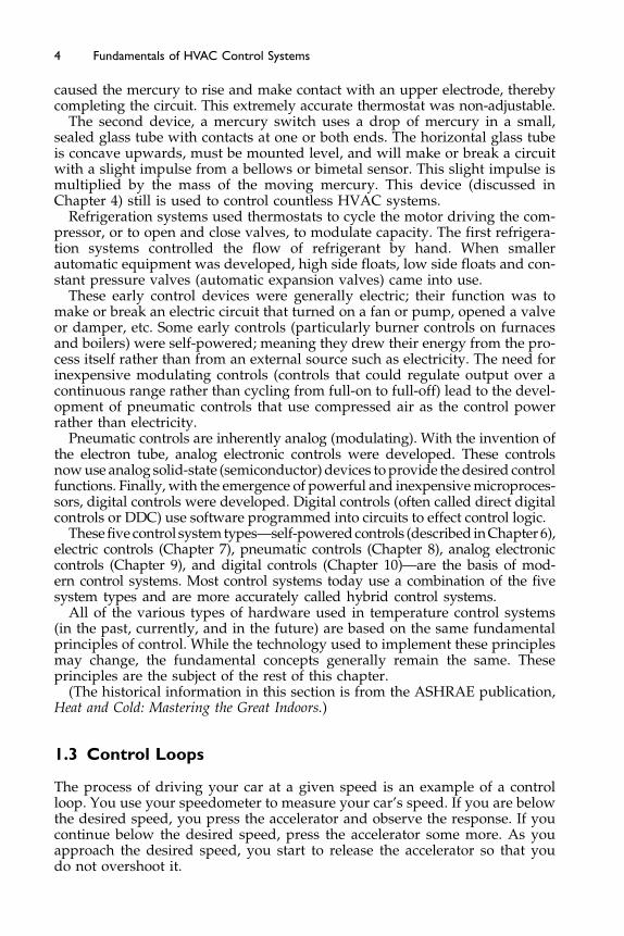
In this example, you are acting as the controller making the control deci-sions whether to press or release the accelerator. The car’s speed is the con-trolled variable and the speedometer is the sensor that measures the currentvalue or control point of the controlled variable. The accelerator is the con-trolled device and your car’s engine is the process plant.Figure 1-1 shows this exchange of information schematically (see also
Table 1-1).It is called a control loop because information flows in a circle from the sen-
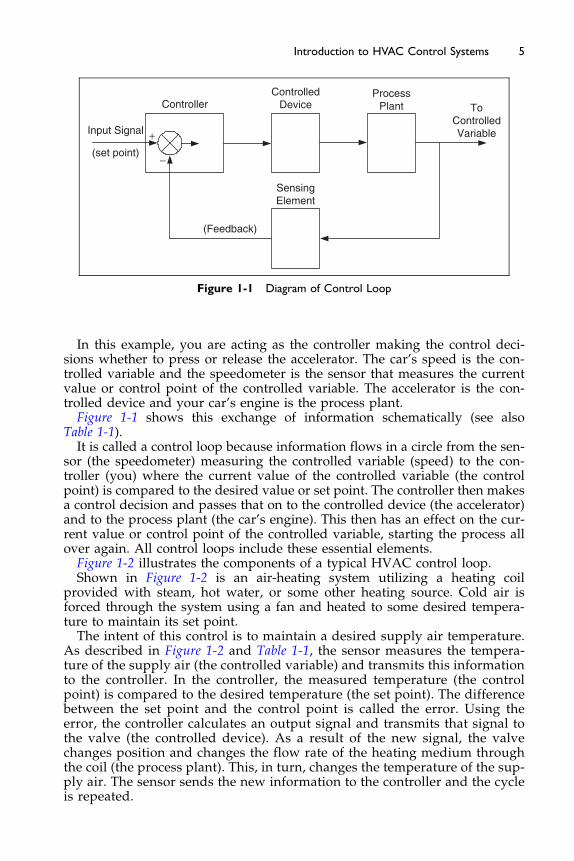
sor (the speedometer) measuring the controlled variable (speed) to the con-troller (you) where the current value of the controlled variable (the controlpoint) is compared to the desired value or set point. The controller then makesa control decision and passes that on to the controlled device (the accelerator)and to the process plant (the car’s engine). This then has an effect on the cur-rent value or control point of the controlled variable, starting the process allover again. All control loops include these essential elements.Figure 1-2 illustrates the components of a typical HVAC control loop.Shown in Figure 1-2 is an air-heating system utilizing a heating coil
provided with steam, hot water, or some other heating source. Cold air isforced through the system using a fan and heated to some desired tempera-ture to maintain its set point.The intent of this control is to maintain a desired supply air temperature.
As described in Figure 1-2 and Table 1-1, the sensor measures the tempera-ture of the supply air (the controlled variable) and transmits this informationto the controller. In the controller, the measured temperature (the controlpoint) is compared to the desired temperature (the set point). The differencebetween the set point and the control point is called the error. Using theerror, the controller calculates an output signal and transmits that signal tothe valve (the controlled device). As a result of the new signal, the valvechanges position and changes the flow rate of the heating medium throughthe coil (the process plant). This, in turn, changes the temperature of the sup-ply air. The sensor sends the new information to the controller and the cycleis repeated.

CController
Sensor
Set point
T
HeatingCoil Air Flow
ControlledDevice
Supply Air Temperature(Controlled Variable)
(ProcessPlant)
Figure 1-2 Simple Heating System
Table 1-1 Control Comparison for Automobile and Heating
Term
Automobile
Example
Heating System
Example Definition
Controller You The device thatprovides a signalto the valve
The device that provides a signalto the controlled device inresponse to feedback from thesensor
Sensor Speedometer Supply airtemperaturesensor
The device that measures thecurrent status of the controlledvariable
Controlleddevice
The accelerator The control valve The device that changes theoperation of the process plant inresponse to a control signal
Controlledvariable
The car speed The supply airtemperature
The signal that the sensor senses
Processplant
The car engine The heating coil The device that produces thechange in the controlled variable
Inputsignal (setpoint)
Desired speed Supply air setpoint
This is the reference or desiredinput that is compared to thecontrolled variable
6 Fundamentals of HVAC Control Systems
Both of these examples are called closed-loop or feedback-control systemsbecause we are sensing the controlled variable and continuously feeding thatinformation back to the controller. The controlled device and process planthave an effect on the controlled variable, which is sensed and fed to the con-troller for comparison to the set point and a subsequent response in the formof a change in controller output signal.
7Introduction to HVAC Control Systems
An open-loop control system does not have a direct link between the valueof the controlled variable and the controller: there is no feedback. An exampleof an open-loop control would be if the sensor measured the outside air tem-perature and the controller was designed to actuate the control valve as afunction of only the outdoor temperature. The variable (in this case, the sup-ply air temperature or perhaps the temperature of the space the systemserved) is not transmitted to the controller, so the controller has no directknowledge of the impact that valve modulation has on these temperaturesmodulating the valve.Another way of defining an open-loop is to say that changes to the con-
trolled device (the control valve) have no direct impact on the variable thatis sensed by the controller (the outdoor air temperature in this case). Withan open-loop control system, there is a presumed indirect connection betweenthe end-result and the variable sensed by the controller.If the exact relationship between the outdoor air temperature and the heat-
ing load was known, then this open-loop control could accurately maintain aconstant space temperature. In practice, this is rarely the case and, therefore,simple open-loop control seldom results in satisfactory performance. For thisreason, almost all HVAC continuous-control systems use closed controlloops.Open-loop control, in the form of time-clocks, or occupancy sensors, are
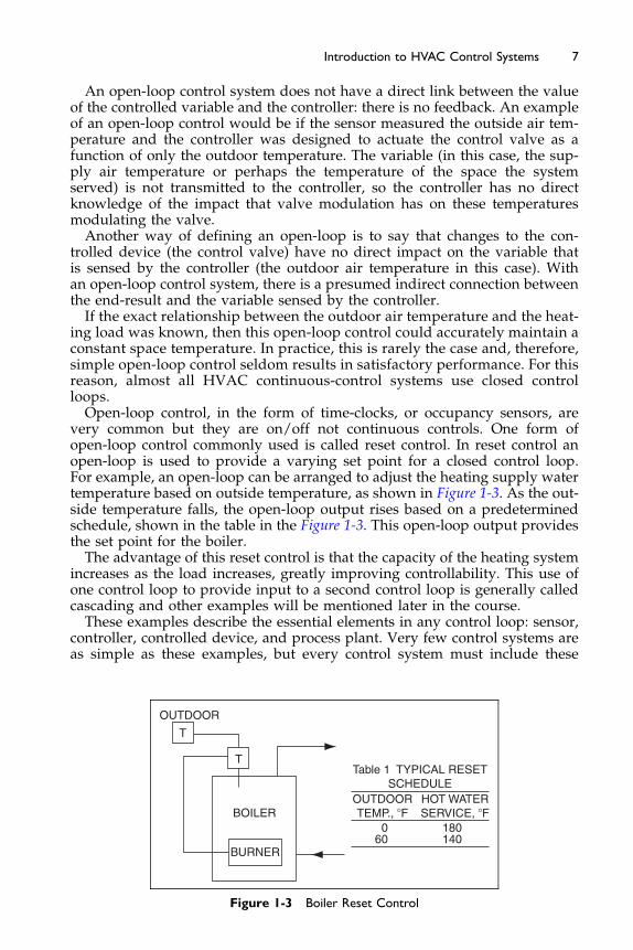
very common but they are on/off not continuous controls. One form ofopen-loop control commonly used is called reset control. In reset control anopen-loop is used to provide a varying set point for a closed control loop.For example, an open-loop can be arranged to adjust the heating supply watertemperature based on outside temperature, as shown in Figure 1-3. As the out-side temperature falls, the open-loop output rises based on a predeterminedschedule, shown in the table in the Figure 1-3. This open-loop output providesthe set point for the boiler.The advantage of this reset control is that the capacity of the heating system
increases as the load increases, greatly improving controllability. This use ofone control loop to provide input to a second control loop is generally calledcascading and other examples will be mentioned later in the course.These examples describe the essential elements in any control loop: sensor,
controller, controlled device, and process plant. Very few control systems areas simple as these examples, but every control system must include these
OUTDOOR
BURNER
BOILER
TTable 1 TYPICAL RESET
SCHEDULEOUTDOORTEMP., �F
060
180140
HOT WATERSERVICE, �F
T
Figure 1-3 Boiler Reset Control
8 Fundamentals of HVAC Control Systems
essential elements. In Chapter 5 we will describe more complex systems, butall of them will be based on elementary control loops. Behind any apparentcomplexity, there must be an elementary system or systems.
Sometimes the sensor and controller are combined in one package. This sen-sor/controller combination is commonly called a stat, such as a thermostat,humidistat, or pressure stat. These devices still contain the individual controlelements (the sensor and the controller); they have simply been mounted intoa single enclosure.
Common controlled devices include control valves, which are used to controlthe flow of water or steam, and control dampers, which are used to control theflow of air. These devices and their proper selection are discussed in Chapter 3.Motor starters, relays, and variable speed drives are also common controldevices; they are discussed in Chapter 2.
Common controlled variables include the temperature, humidity, pressure,and velocity of air in conditioned spaces and in ductwork, and the tempera-ture, velocity, and pressure of water in hydronic heating and cooling systems.Sensors used to measure these variables come in a variety of types with vary-ing degrees of accuracy. The accuracy of the measurement naturally affectsthe accuracy of control. Sensors are discussed in Chapter 4.
Typically, between the controller and the controlled device, there is an actu-ator attached to the controlled device through connectors called the linkage.Actuators are devices that convert the signal from the controller into a physi-cal force that causes the controlled device (damper or valve) to move. Actua-tor characteristics vary by the type of control system used and are discussedin Chapters 6 through 10.
This section introduced some fundamental terms used in control systems. It isvery important that these terms are well understood so that you understand theremaining sections of this chapter. The following is a summary of key terms:
Controlled variable: the property that is to be controlled, such as temperature,humidity, velocity, flow and pressure.
Control point: the current condition or value of the controlled variable.Set point: the desired condition or value of the controlled variable.Sensor: the device that senses the condition or value of the controlled (or
“sensed”) variable.Sensed variable: the property (temperature, pressure, humidity) that is being
measured. Usually the same as the controlled variable in closed-loopcontrol systems.
Controlled device: the device that is used to vary the output of the processplant, such as a valve, damper, or motor control.
Process plant: the apparatus or equipment used to change the value of thecontrolled variable, such as a heating or cooling coil or fan.
Controller: the device that compares the input from the sensor with the setpoint, determines a response for corrective action, and then sends thissignal to the controlled device.
Control loop: the collection of sensor, controlled device, process plant, andcontroller.
Closed-loop: a control loop where the sensor is measuring the value of thecontrolled variable, providing feedback to the controller of the effectof its action.
9Introduction to HVAC Control Systems
Open-loop: a control loop where the sensor is measuring something otherthan the controlled variable. Changes to the controlled device and pro-cess plant have no direct impact on the controlled variable. There is an“assumed” relationship between the property that is measured and theactual variable that is being controlled.
1.4 Control Modes
The purpose of any closed-loop controller is to maintain the controlled vari-able at the desired set point. All controllers are designed to take action inthe form of an output signal to the controlled device. The output signal is afunction of the error signal, which is the difference between the control pointand the set point. The type of action the controller takes is called the controlmode or control logic, of which there are three basic types:
� two-position control� floating control� modulating control
Within each control-mode category, there are subcategories for each of thespecific control algorithms (procedures, methods) used to generate the outputsignal from the error signal, and other enhancements used to improveaccuracy.The various control modes and subcategories are simply different ways of
achieving the desired result: that the controlled variable be maintained at setpoint. It is often a difficult task because the dynamics of the HVAC system,the spaces it serves, and the controls themselves can be very complex. Thereare generally time lags between the action taken by the controller and theresponse sensed by the sensor.For instance, in the heating system depicted in Figure 1-2, it takes time for
the valve to move when given a signal from the controller; then it takes a littlemore time for the water to begin to flow. If the coil has not been used in awhile, it will take time to warm its mass before it can begin warming theair. If the sensor was located in the space served by the system (as opposedto in the supply duct, as shown in Figure 1-2), there would be even more timedelays as the air travels down the duct to the diffusers and begins to mix withand warm the air in the space. There will be a delay as the air warms the sur-faces in the space (the space envelope, walls, and furnishings) before it warmsthe surfaces and air near the sensor. There can also be a delay as the sensoritself takes time to warm up and reach a new steady-state condition, and theremay be a delay in transferring that information back to the controller. Finally,the controller can take time to compare the sensor signal to the set point andcalculate a response. The effect of all these delays is called the system timeconstant. If the time constant is short, the system will react quickly to a changein the controlled device or process plant; if the time constant is long, the sys-tem will be sluggish to changes in the controlling devices.Another factor that affects the performance of a controller is the system gain.
As shown in Table 1-2, the controller gain describes how much the controlleddevicewill change for a given change in the controlled device and process plant.

Table 1-2 Controller Gain
Controller Setting Controller Gain Control Action
Open valve from zero to100% for a 1�F change inmeasured variable
Higher Small change in measured variablecreates a big change in output. 1�Fcauses controller to request 100%valve opening
Open valve from zero to100% for a 5�F change inmeasured variable
Lower Large change in measured variablerequired to create a significantchange in output. 1�F causescontroller to request only 20%valve opening
10 Fundamentals of HVAC Control Systems
The gain of the controller is only part of the issue. The capacity of the controlleddevice also influences the system gain. Thus, at full load, if full output justmatches the requirement, then the controller gain is the same as the system gain.However, let us imagine that the required output is met with the controlleddevice only half open. In effect the system capacity is twice what is required.The system gain is now the controller gain divided by the system overcapacity,i.e. the gain is doubled. Thus, system gain is a function of controller gain and afunction of how much capacity the system has relative to the load the systemexperiences. A system with a high gain means that a small change in the signalto the controlled device will cause a large change in the controlled variable. Inthe extreme case, the system is said to be oversized and good control is virtuallyimpossible as even a small change in measured variable produces a huge changein output. The outdoor reset shown in Figure 1-3 is an example of adjusting thesystem capacity to avoid the effect of overcapacity at low loads.
If all of these time delays and gains are fairly linear and consistent, the con-troller can generally be adjusted (tuned) to provide accurate control, but, theremay be non-linearitys, such as hysteresis (delay, or uneven response) in thecontrol valve. In this example, this is a delay caused by friction that bindsthe actuator or valve stem, thereby preventing a smooth, linear movement.There may also be changes to the system that change its gain, such as a vary-ing hot water supply temperature to the heating coil, or a varying airflow ratethrough the coil. These complications can be handled with varying degrees ofsuccess and accuracy by the various control modes described in the followingsections.
Two-position Control
The simplest and probably most common control mode is two-position con-trol. It applies to systems that have only two states, such as On and Off fora fan or pump, or Open and Closed for a valve or damper. Small HVAC sys-tems, such as the furnaces and air conditioners found in most residences, areexamples of two-position systems. Systems that only have two states ofoperation are almost always controlled using two-position controls.
Figure 1-4 shows the action of a two-position control of a heating thermostatfor the heating system.

ColderOff
On
Set pointTemperature
Warmer
Differential
Figure 1-4 Two-position Control Diagram for a Heating System
11Introduction to HVAC Control Systems
Figure 1-5 shows what happens with this control when the controller respondsto supply air that is colder than the desired set point at about 50% load.The two positions in this case are the valve full-open (allowing full flow of
hot water or steam through the coil), and the valve full-closed (no flow).Along the vertical axis is the value of the controlled (or “sensed”) variable(the supply air temperature), while time is on the horizontal axis.Looking again at Figure 1-2 and starting at the left of Figure 1-5, because the
air entering the coil is colder than the desired set point, the air temperaturesensed by the supply temperature sensor begins to fall. Just as it falls belowthe set point (represented by the lower dashed horizontal line in the figure),the controller causes the valve to open. The heating medium flows to the coil,but the air temperature will not rise immediately because it takes time for theactuator to open the valve and for the coil mass to begin to warm before itstarts to warm the air. So the air temperature continues to fall below the setpoint before it turns around and begins to rise.The valve will stay open until the supply air temperature rises by the control
differential above the set point. The control differential is a fixed difference insensed value between the open and closed commands; it is representedin Figure 1-5 by the difference between the set point and the higher dashed
Con
trol
Diff
eren
tial
ON
ControlledVariable
Set pointON
Time
ON
OFF OFF
Ope
ratin
gD
iffer
entia
l
Figure 1-5 Two-position Heating Control
12 Fundamentals of HVAC Control Systems
horizontal line. When the air temperature intersects this line, the controllercloses the valve. Again, there is a time delay before the air temperature beginsto fall because the heating medium in the coil and the coil itself must first cooloff. Eventually the air temperature falls until it reaches the set point again,and the cycle is repeated. In this example, the set point is shown to be the on-point (the point where the valve is opened), and the set point plus control differ-ential is the off-point (where the valve is closed). It is also common to show theset point as being the midpoint between the on-point and off-point because thisis the average condition of the controlled variable as the valve cycles opened andclosed. In practice, however, the set point for a typical two-position thermostat(the point set by adjusting the set point knob) is usually either the on-point (asshown in Figure 1-5) or the off-point. It very seldom corresponds to themidpointof the differential.
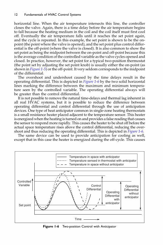
The overshoot and undershoot caused by the time delays result in theoperating differential. This is depicted in Figure 1-6 by the two solid horizontallines marking the difference between the maximum and minimum tempera-ture seen by the controlled variable. The operating differential always willbe greater than the control differential.
It is not possible to remove the natural time-delays and thermal lag inherent inall real HVAC systems, but it is possible to reduce the difference betweenoperating differential and control differential through the use of anticipationdevices. One type of heat anticipator common in single-zone heating thermostatsis a small resistance heater placed adjacent to the temperature sensor. This heateris energizedwhen theheating is turnedonandprovides a false reading that causesthe sensor to respondmore rapidly. This causes the heater to be shut off before theactual space temperature rises above the control differential, reducing the over-shoot and thus reducing the operating differential. This is depicted in Figure 1-6.
The same device can be used to provide anticipation for cooling as well,except that in this case the heater is energized during the off-cycle. This causes
ControlledVariable
Set point
Time
ControlDifferential
OperatingDifferential
withanticipator
OperatingDifferential
withoutanticipator
Temperature in space with anticipatorTemperature sensed in thermostat with anticipatorTemperature in space without anticipator
Figure 1-6 Two-position Control with Anticipator

13Introduction to HVAC Control Systems
the sensor signal to rise more quickly above set point, which then turns thecooling on more quickly, again reducing the operating differential.Despite the use of anticipation devices, the very existence of a control differen-
tial results in temperature fluctuations. The air temperature is only at the desiredcondition (the set point) for a fewmoments. Control could bemademore accurateby decreasing the control differential, but too small a differential will result inrapid cycling, called short-cycling. Short-cycling usually leads to inefficiencies inthe heating or cooling system, and almost always shortens the life of equipment.The ability of two-position control to function well (its ability to maintain the
controlled variable near set pointwith a reasonable operating differentialwithoutshort-cycling) is a function of the system gain, which is a function of the design ofthe HVAC system the control system. The capacity of the process plant (the heat-ing or cooling system) must not greatly exceed the actual load experienced. If itdoes, then either the control differential must be increased, resulting in an unac-ceptablywideoperatingdifferential, or the systemmust be allowed to short-cycle.As with many control applications, the control system cannot compensate for apoor HVAC system design.Where a wide variation in load is expected, if the system gain is too high
due to process plant capacity that far exceeds the load at any given time, anHVAC system with continuously varying capacity or multiple capacity stepsshould be used. Systems with continuous capacity are controlled using eitherfloating or modulating controls, as discussed in the next two sections. Systemswith multiple capacity steps are controlled by step controls.Step control is actually a series of two-position controls controlling the same
controlled variable but at slightly different set points. Step control is used tocontrol systems with multiple stages of capacity, such as multi-speed motors(high–low–off), multi-stage gas burners (high-fire, low-fire, off), or multi-stagerefrigeration systems (multiple compressors, multi-speed compressors, orcompressors with cylinder unloading). Figure 1-7 shows how a step controller
Time
Set pointStage 1
ControlledVariable
Stage 1 off Stage 1 on Stage 2 off
Stage 2 on
B
A
C
Stage 1 still on
Set pointStage 2
ABC
Operating Differential, Stage 1Operating Differential, Stage 2
Overall Operating Differential
Figure 1-7 Step Control
14 Fundamentals of HVAC Control Systems
might operate with a heating system that had two heating stages for a total ofthree operating positions (high-fire, low-fire, and off).
As the temperature falls below the Stage 1 set point, the first step of heating isturned on. If this were enough capacity to handle the load, the temperaturewould cycle around this set point and its control differential just as it wouldwith two-position control. If, as depicted in Figure 1-7, the temperature wereto continue to fall below the Stage 2 set point, the second heating stage wouldbe turned on. Operation is then just like two-position control around this setpoint. Note that the control operating ranges overlap; the temperature at whichthe first stage comes on is lower than the temperature at which the second stagegoes off. The set points and control differentials could have been set for non-overlapping ranges where the first-stage on-point was equal to or above the sec-ond stage off-point. However, overlapping the ranges reduces the overalloperating differential without using small operating differentials for each stage.In this way, fine control can be provided without short-cycling stages.
Floating Control
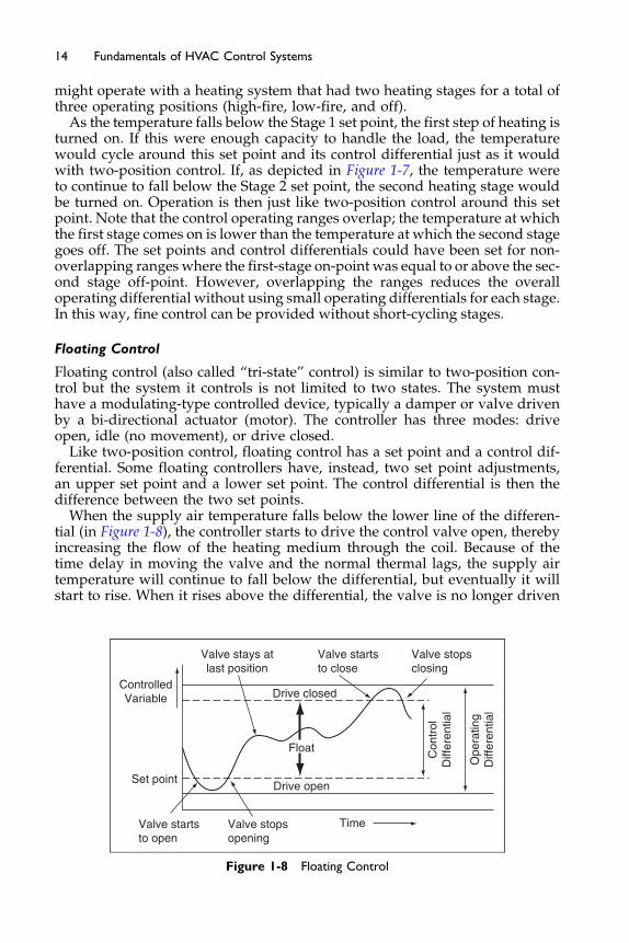
Floating control (also called “tri-state” control) is similar to two-position con-trol but the system it controls is not limited to two states. The system musthave a modulating-type controlled device, typically a damper or valve drivenby a bi-directional actuator (motor). The controller has three modes: driveopen, idle (no movement), or drive closed.
Like two-position control, floating control has a set point and a control dif-ferential. Some floating controllers have, instead, two set point adjustments,an upper set point and a lower set point. The control differential is then thedifference between the two set points.
When the supply air temperature falls below the lower line of the differen-tial (in Figure 1-8), the controller starts to drive the control valve open, therebyincreasing the flow of the heating medium through the coil. Because of thetime delay in moving the valve and the normal thermal lags, the supply airtemperature will continue to fall below the differential, but eventually it willstart to rise. When it rises above the differential, the valve is no longer driven
ControlledVariable
Valve startsto open
Valve stopsopening
Drive open
Drive closed
Valve stays atlast position
Valve startsto close
Valve stopsclosing
Con
trol
Diff
eren
tial
Ope
ratin
gD
iffer
entia
l
Float
Time
Set point
Figure 1-8 Floating Control
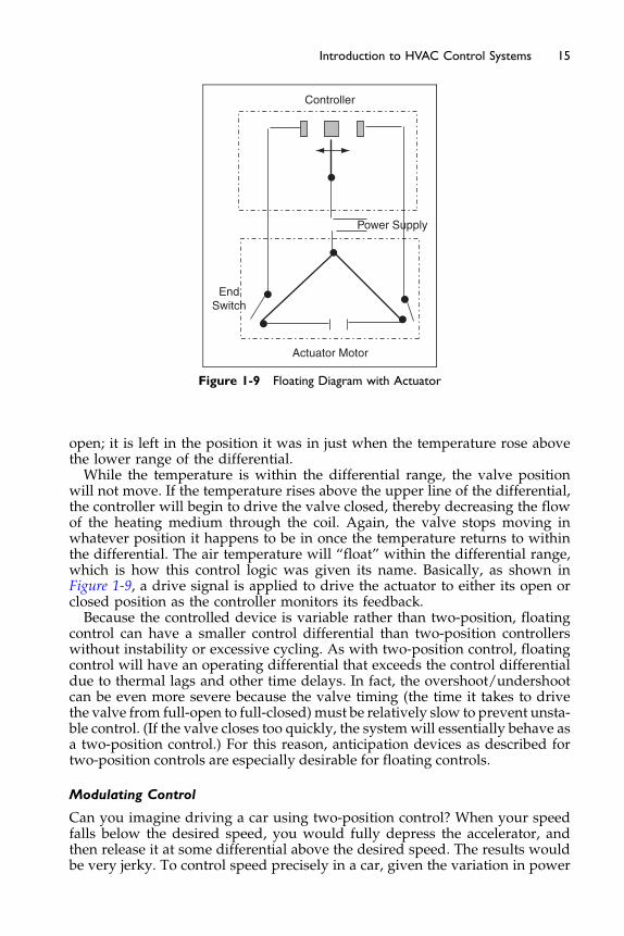
Actuator Motor
Power Supply
EndSwitch
Controller
Figure 1-9 Floating Diagram with Actuator
15Introduction to HVAC Control Systems
open; it is left in the position it was in just when the temperature rose abovethe lower range of the differential.While the temperature is within the differential range, the valve position
will not move. If the temperature rises above the upper line of the differential,the controller will begin to drive the valve closed, thereby decreasing the flowof the heating medium through the coil. Again, the valve stops moving inwhatever position it happens to be in once the temperature returns to withinthe differential. The air temperature will “float” within the differential range,which is how this control logic was given its name. Basically, as shown inFigure 1-9, a drive signal is applied to drive the actuator to either its open orclosed position as the controller monitors its feedback.Because the controlled device is variable rather than two-position, floating
control can have a smaller control differential than two-position controllerswithout instability or excessive cycling. As with two-position control, floatingcontrol will have an operating differential that exceeds the control differentialdue to thermal lags and other time delays. In fact, the overshoot/undershootcan be even more severe because the valve timing (the time it takes to drivethe valve from full-open to full-closed)must be relatively slow to prevent unsta-ble control. (If the valve closes too quickly, the systemwill essentially behave asa two-position control.) For this reason, anticipation devices as described fortwo-position controls are especially desirable for floating controls.
Modulating Control
Can you imagine driving a car using two-position control? When your speedfalls below the desired speed, you would fully depress the accelerator, andthen release it at some differential above the desired speed. The results wouldbe very jerky. To control speed precisely in a car, given the variation in power
16 Fundamentals of HVAC Control Systems
required from accelerating onto the freeway to coasting down a residentiallane, a system of continuously varying capacity control is required: the accel-erator. Many HVAC systems face similar widely varying loads and are alsofitted with continuous or nearly continuous capacity capability. Whencontrolling systems with this capability, you can improve the accuracy of con-trol by using modulating control logic, the subject of this section.
Note that just because the system has a continuously variable output capabilityit does not limit you to using modulating controls. You could still drive your carwith two-position control by alternately pressing and releasing the accelerator(although with not very satisfactory results). Early cruise control systems usedfloating control logic to control speed (as do some poor drivers, it seems). Con-versely, systems that are inherently two-positionormulti-position (such as stagedrefrigeration systems) are not limited tousing two-position controllers.Aswewillsee below, these systems can also benefit from modulating control techniques.
Modulating control is sometimes called analog control, drawing on the par-allel between modulating/two-position and analog/digital. For many years,the term proportional control was used to mean modulating control becausethe controllers at that time were limited to proportional control logic(described below). Modern modulating controls use more sophisticated algo-rithms that go beyond simple proportional logic.
Remember that automatic controls simply imitate the human logic youwould apply during manual control. To understand some of the control logicyou use without consciously thinking about it, imagine you are trying to driveyour car at a constant speed. While the road is flat or at a steady slope you canmaintain a constant speed while pressing the accelerator to a fixed position.As you start to climb a hill, you begin to lose speed, so you begin to pressthe accelerator some more. If you slowed only a little below your desiredspeed, you may only press the accelerator a little more. The further you fallbelow the desired speed, the more you would press the accelerator.
After a while, you may find that you are no longer decelerating, but thespeed you are maintaining, while constant, is still below that desired. The lon-ger you stay below the desired speed, the more inclined you are to press theaccelerator more to get back up to speed. However, let us say that, beforeyou get up to speed, the terrain changes and you start to go down a hill. Yourspeed begins to increase toward the desired speed, but at a rate that you senseis too fast. To prevent from shooting past the speed you desire, you begin toback off of the accelerator even though you are still below the desired speed.As the terrain changes, you continuously go through many of these samethought processes over and again.
While you certainly do not think of them this way, the thought processesyou use to drive your car can be approximated mathematically as:
V ¼ V0 þ Vp þ Vi þ Vd
¼ V0 þ Kpeþ Ki
Ðe dtþ Kd
de
dtðEquation 1-1Þ
In this expression, V is the output of the controller. Using our example, V ishow much you press the accelerator.
17Introduction to HVAC Control Systems
The first term on the right-hand side of the equation, V0, is called the offsetadjustment. It is the amount you have to press the accelerator when you aredriving on a flat road or a road with a steady slope, and to keep your carcruising steadily at the speed you desire.The second term, Vp, is called the proportional term. It is proportional to the
error e, which is the difference between actual speeds and the desired speed orset point. When you sense that the further you are from the desired speed, themore you should press the accelerator, you are using proportional control logic.The third term, Vi, is called the integral term. It is proportional to the inte-
gral of the error over time. For those of you not familiar with calculus, theintegral term is essentially a time-weighted average of the error; how muchare you away from set point multiplied by how long you have been thatway. In our example, when you sensed that you stayed below the desiredspeed for too long and thus pressed the accelerator more to increase speed,you were using integral control logic.The last term Vd, is called the derivative term. It is proportional to the deriv-
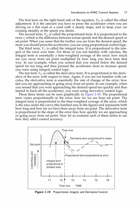
ative of the error with respect to time. Again, if you are not familiar with cal-culus, the derivative term is essentially the rate of change of the error; howfast you are approaching or going away from set point. In our example, whenyou sensed that you were approaching the desired speed too quickly and thusstarted to back-off the accelerator, you were using derivative control logic.These three terms can be seen graphically in Figure 1-10. The proportional
term varies proportionally to the error: how far we are from set point. Theintegral term is proportional to the time-weighted average of the error, whichis the area under the curve (the hatched area in the figure) and represents bothhow long and how far we have been away from set point. The derivative termis proportional to the slope of the error line; how quickly we are approachingor going away from set point. Now let us examine each of these terms to seehow they affect control accuracy.
Integral termproportional toshaded area
Proportional term proportional to error
Derivative term proportional to slope
Time now
Set point
T1 T2 T3
Time now TIME
T4 T5 T6
CO
NT
RO
LLE
DV
AR
IAB
LE
Figure 1-10 Proportional, Integral, and Derivative Control
18 Fundamentals of HVAC Control Systems
First, if we remove the integral and derivative terms from Equation 1-1,we get:
V ¼ V0 þ Kpe ðEquation 1-2Þ
This is the mathematical expression of proportional-only control logic. Pro-portional control is the simplest and most common modulating control logic.Virtually all pneumatic thermostats, most pneumatic controllers, and mostanalog electronic controllers use it.
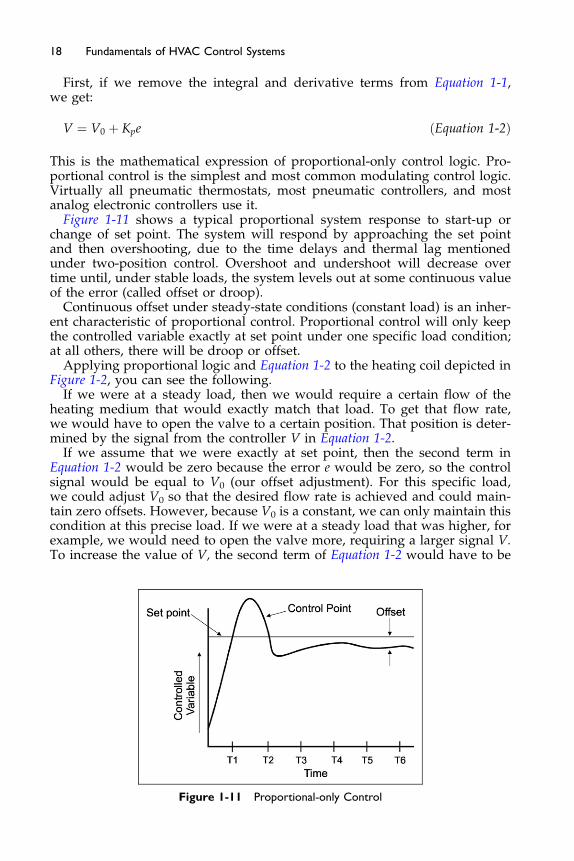
Figure 1-11 shows a typical proportional system response to start-up orchange of set point. The system will respond by approaching the set pointand then overshooting, due to the time delays and thermal lag mentionedunder two-position control. Overshoot and undershoot will decrease overtime until, under stable loads, the system levels out at some continuous valueof the error (called offset or droop).
Continuous offset under steady-state conditions (constant load) is an inher-ent characteristic of proportional control. Proportional control will only keepthe controlled variable exactly at set point under one specific load condition;at all others, there will be droop or offset.
Applying proportional logic and Equation 1-2 to the heating coil depicted inFigure 1-2, you can see the following.
If we were at a steady load, then we would require a certain flow of theheating medium that would exactly match that load. To get that flow rate,we would have to open the valve to a certain position. That position is deter-mined by the signal from the controller V in Equation 1-2.
If we assume that we were exactly at set point, then the second term inEquation 1-2 would be zero because the error e would be zero, so the controlsignal would be equal to V0 (our offset adjustment). For this specific load,we could adjust V0 so that the desired flow rate is achieved and could main-tain zero offsets. However, because V0 is a constant, we can only maintain thiscondition at this precise load. If we were at a steady load that was higher, forexample, we would need to open the valve more, requiring a larger signal V.To increase the value of V, the second term of Equation 1-2 would have to be
Figure 1-11 Proportional-only Control
19Introduction to HVAC Control Systems
non-zero, meaning our error would have to be non-zero. This error is the off-set or droop.The amount of the offset is a function of the constant Kp (the controller pro-
portional gain). The larger the gain is, the smaller the offset. However, increas-ing the gain to minimize offset must be done with care because too high a gainmay result in instability and a rapid oscillation around the set point (calledhunting). This is because the larger gain causes the valve signal to be largerwhen there are small values of error, thereby causing the system to overreactto small changes in load. This overreaction causes an even larger error in theother direction, which again causes a large change in the valve signal, and weovershoot in the other direction. Adjusting the gain for stable control (minimaloffset without hunting) is called tuning the control loop and is discussedfurther in Section 1.5.A more common way of expressing the proportional gain is the term throt-
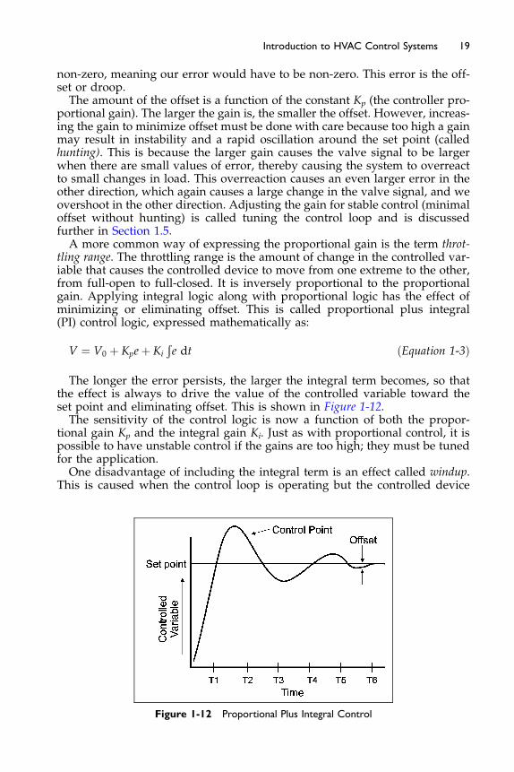
tling range. The throttling range is the amount of change in the controlled var-iable that causes the controlled device to move from one extreme to the other,from full-open to full-closed. It is inversely proportional to the proportionalgain. Applying integral logic along with proportional logic has the effect ofminimizing or eliminating offset. This is called proportional plus integral(PI) control logic, expressed mathematically as:
V ¼ V0 þ Kpeþ Ki
Ðe dt ðEquation 1-3Þ
The longer the error persists, the larger the integral term becomes, so thatthe effect is always to drive the value of the controlled variable toward theset point and eliminating offset. This is shown in Figure 1-12.The sensitivity of the control logic is now a function of both the propor-
tional gain Kp and the integral gain Ki. Just as with proportional control, it ispossible to have unstable control if the gains are too high; they must be tunedfor the application.One disadvantage of including the integral term is an effect called windup.
This is caused when the control loop is operating but the controlled device
Figure 1-12 Proportional Plus Integral Control
20 Fundamentals of HVAC Control Systems
is disconnected or otherwise not able to control the controlled variable, suchas when a system is turned off at night. In this case, the controlled variablecannot be maintained at set point, so the integral term becomes larger andlarger. When the system is turned on, the value of V is fully in one directionand the system will usually overshoot the set point. It takes time for the inte-gral term to fall because of the long period that the system was far from setpoint. This effect (windup) causes the system to be temporarily unstable.
The problem can bemitigated by simply disabling the controller when the sys-tem is turned off (the preferred solution), by adding derivative control (discussedbelow), or by any number of anti-windup devices or algorithms commonly usedwith analog electronic controllers. A common anti-windup algorithm is to useproportional logic only until the system has been on for a period of time.
PI control is available with many pneumatic and analog electronic controls.It is virtually standard on digital control systems.
Using all three terms of Equation 1-1 is called proportional plus integral plusderivative (PID) control logic. Adding the derivative term reduces overshoot-ing. It has the effect of applying “brakes” to overreacting integral terms. Typi-cally, derivative control has a very fast response, which makes it very usefulin such applications as fast acting industrial processes and rocketry. However,because most HVAC system responses are relatively slow, the value of deriv-ative control in most HVAC applications is minimal. Including the differentialterm may complicate the tuning process, and cause unstable responses. Forthese reasons, derivative control logic is normally not used in most field HVACapplications. (Note that the generic control loop, particularly in digital controlapplications, is often referred to as a PID loop, even though the derivativefunction is typically unused.)
While PID logic is generally applied to systems with continuous or modulat-ing capacity capability, it may also be applied to systems with staged capacitycapability to improve the accuracy versus two-position control logic. The waythis is usually done is by applying a modulating control loop to the controlledvariable, the output of which (V) is a “virtual” output (an output that does notactually control a real device). Then, step control logic is applied to a second con-trol loop using the signal V as its controlled variable. The output of this secondloop sequences the capacity stages of the equipment. Using PID logic in thismanner can result in a smaller operating differential than using step controllogic, particularly if the system has many steps of control (four or more).
Pulse-width Modulating, and Time-proportioning Control
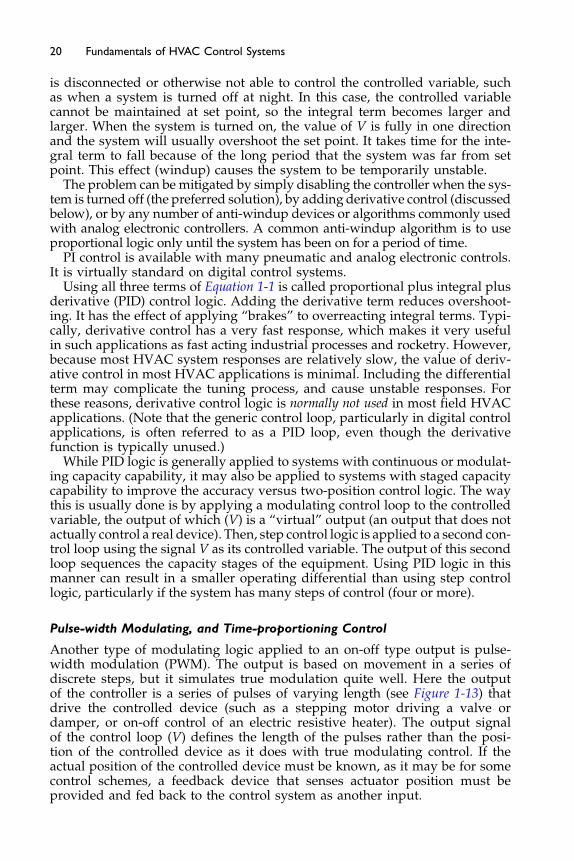
Another type of modulating logic applied to an on-off type output is pulse-width modulation (PWM). The output is based on movement in a series ofdiscrete steps, but it simulates true modulation quite well. Here the outputof the controller is a series of pulses of varying length (see Figure 1-13) thatdrive the controlled device (such as a stepping motor driving a valve ordamper, or on-off control of an electric resistive heater). The output signalof the control loop (V) defines the length of the pulses rather than the posi-tion of the controlled device as it does with true modulating control. If theactual position of the controlled device must be known, as it may be for somecontrol schemes, a feedback device that senses actuator position must beprovided and fed back to the control system as another input.
time
ON
OFF
Figure 1-13 Pulse-width Modulation
ON
timeFixedCycleTime
OFF
Figure 1-14 Time-proportioning Control
21Introduction to HVAC Control Systems
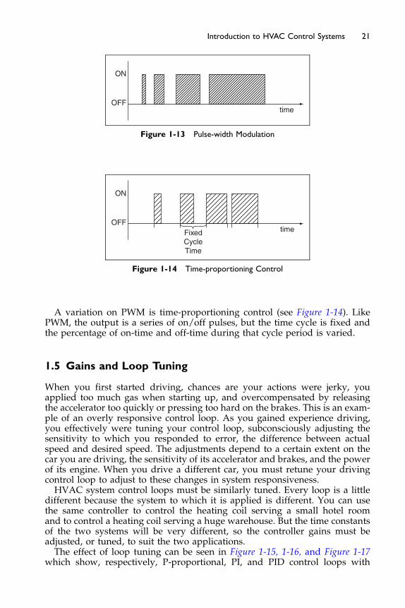
A variation on PWM is time-proportioning control (see Figure 1-14). LikePWM, the output is a series of on/off pulses, but the time cycle is fixed andthe percentage of on-time and off-time during that cycle period is varied.
1.5 Gains and Loop Tuning
When you first started driving, chances are your actions were jerky, youapplied too much gas when starting up, and overcompensated by releasingthe accelerator too quickly or pressing too hard on the brakes. This is an exam-ple of an overly responsive control loop. As you gained experience driving,you effectively were tuning your control loop, subconsciously adjusting thesensitivity to which you responded to error, the difference between actualspeed and desired speed. The adjustments depend to a certain extent on thecar you are driving, the sensitivity of its accelerator and brakes, and the powerof its engine. When you drive a different car, you must retune your drivingcontrol loop to adjust to these changes in system responsiveness.HVAC system control loops must be similarly tuned. Every loop is a little
different because the system to which it is applied is different. You can usethe same controller to control the heating coil serving a small hotel roomand to control a heating coil serving a huge warehouse. But the time constantsof the two systems will be very different, so the controller gains must beadjusted, or tuned, to suit the two applications.The effect of loop tuning can be seen in Figure 1-15, 1-16, and Figure 1-17
which show, respectively, P-proportional, PI, and PID control loops with

Kp% is the percent of input rangerequired to cause 100% output
Time
Control Point with1.5% prop. gain
Set pointChange
ControlledVariable
Control Point with3% prop. gain Control Point with
7% prop. gain
Set point Kp = 7% Kp = 3% Kp = 1.5%
Figure 1-15 Proportional Control
ControlledVariable
Time
Set point Kp = 1.5Ki = 0.2
Kp = 1.5Ki = 0.1
Kp = 1.5Ki = 0.05
Figure 1-16 Proportional-integral Control
Set pointKp = 2
Time
ControlledVariable
Ki = 0.08Kd = 0
Kp = 2Ki = 0.08Kd = 1
Kp = 2Ki = 0.08Kd = 2
Figure 1-17 Proportional-integral-derivative Control
23Introduction to HVAC Control Systems
various gains. These figures show how the controller responds to step changesin set point. Except when a system is first started each day, it is unlikely inmost HVAC applications to abruptly change set points in this way. But, theresponse would be similar to large changes in heating and cooling loads, asmight occur when an assembly room is quickly occupied, for instance. Ascan be seen by the curves, the accuracy and stability of the control can be opti-mized by selecting the proper proportional, integral, and derivative gains.Loop tuning is currently somewhat of an art and is usually done empirically by
trial-and-error. The technique is typically to tune the proportional gain first, thenadjusting the integral gain to eliminate offset. (As noted above, the derivative gainis usually not used, at least partly because it complicates this tuning process.) ThePID gains are initially set to values based on rules-of-thumb, manufacturerrecommended values, or learned from experience with similar applications.The control technician will then observe the system in action and adjust the gainupward until oscillation is detected. If trend logging is available, the performanceshouldbeviewedover time. Thegain adjustmentswill thenbe backedoff to aboutone-half of the high value. (Note: defined performance of PID values may per-form differently from one manufacturer to another.) The more experienced thetechnician is, the more precisely and more quickly the loop will be tuned. Thisprocedure, while not optimum, will usually provide reasonable results.More precise loop tuning techniques can be applied, but usually the process
is too cumbersome to be done manually. Some digital control systems includeautomatic loop tuning software that applies these more rigorous loop-tuningtechniques to automatically tune loops without input from the technician.Proportional- or P-control logic assumes that processes are linear; the func-
tion that describes the error has the same characteristics independent ofoperating conditions. Most real processes are nonlinear and thus PID logicmay be very difficult to set up to maintain zero error under all conditions.For instance, when the valve serving the heating coil in Figure 1-2, it is
opened only slightly, and the supply temperature will rise very quickly. Thisis an inherent characteristic of steam or hot water heating coils. After the valveis opened 50%, opening it further has little impact on the supply air tempera-ture. If we tune the loop to maintain excellent control when water (or steam)flow rates are high, it may be too sluggish and will provide poor control whenwater (or steam) flows are low. Conversely, if we tune the loop when flowsare low, it may be too responsive and become unstable when flows are high.To mitigate this problem, loops could be dynamically self-tuned, meaning
the gains could be automatically and continuously adjusted to maintain pre-cise control regardless of operating conditions. Some digital control systemshave this capability and more systems are expected to as more “robust” (fastresponding) self-tuning techniques are developed. Dynamic self-tuning alsoreduces commissioning time because it eliminates the need for manual tuning.Another means to mitigate the non-linearity problem is through the use of
fuzzy logic, which is a relatively new alternative to PID control logic. Fuzzylogic imitates human intuitive thinking by using a series of fuzzy, almost intu-itive, if-then rules to define control actions. Neural networks are another tech-nique for self-tuning using artificial intelligence to “learn” how a systembehaves under various conditions and the proper response to maintain con-trol. More information on fuzzy logic, artificial intelligence, and neural networkscan be obtained in more advanced controls classes and texts.

24 Fundamentals of HVAC Control Systems
1.6 Control Actions and Normal Position
Controllersmaybedirect acting (DA)or reverse acting (RA). These termsdescribethe control action or direction of the controller output signal relative to the direc-tion of a change in the controlled variable. Direct acting means that the controlleroutput increases as the value of the controlled variable increases. Reverse actingmeans that the controller output decreases as the value of the controlled variableincreases. For example, a cooling valve is to control discharge air temperature at aset point. If the discharge air temperature is above set point the valve signal maybe increased to open the valve to allow more cold water to flow through the coil.We would call this “direct acting,” as when the temperature being controlled isabove set point,wewould increase the signal to the valve;wewould say “temper-ature up, signal up,”which depicts direct acting. Similarly, controlling heat is typ-ically reverse acting: if the temperature was below set point, the signal would beincreased or turned on. We would say “temperature down, signal up.”
The term control action must be used with care because it is used in practiceto describe many different control system characteristics. The term is usedmost commonly as above to describe the direction of the output signal relativeto the direction of change of the controlled variable. But it is also frequentlyused to describe what is termed here as the control mode (for example, two-position action, floating action, modulating, etc.). It can also be used todescribe the type of control logic used for modulating control (for example,proportional action, integral action, etc.).
Figure 1-18 shows how direct acting and reverse acting signals look usingproportional control logic. The signal varies in direct proportion to the errorsignal, as described mathematically in Equation 1-2. The magnitude of theslope of the line is the proportional gain while the sign of the slope is positivefor direct acting and negative for reverse acting. The throttling range is the
ReverseActing
Max.Position
Min.Position
ControlOutput
ControlledVariable
ThrottlingRange
DirectActing
Set point
Figure 1-18 Proportional Control
100 Closed
NormallyOpen
Open
SET POINT
Controlled VariableDirect Acting Controller
Reverse Acting Controller
+−
75
50
Con
trol
Out
put
25
0
100 Closed
NormallyOpen
Open
SET POINT
Controlled Variable
+−
75
50
Con
trol
Out
put
25
0
100 Open
NormallyClosed
Closed
SET POINT
Controlled Variable
+−
75
50
Con
trol
Out
put
25
0
100
Closed
NormallyClosed
Open
SET POINT
Controlled Variable
+−
75
50
Con
trol
Out
put
25
0
Figure 1-19 Control Action and Normal Position
25Introduction to HVAC Control Systems
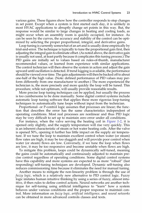
difference in the value of the controlled variable to cause the controlled deviceto go from full-open to full-closed (see also Figure 1-19). Note how the setpoint is depicted as being in the center of the throttling range rather than atone extreme, as we depicted it for two-position and floating controls (Figure 1-4 through Figure 1-8). This is a typical representation of proportional controllogic. However, in practice, proportional controllers can be calibrated so thatthe set point (as it is set using the set point adjustment knob on the controller)is represented by any point within the throttling range (for example, thatcorresponding to fully open, fully closed, or any place in between).Controlled devices (such as dampers, valves, and switches) may be nor-
mally open (NO) to flow through the process plant or normally closed (NC)to flow. These terms describe the so-called normal position of the damper,valve, or contact, which is the position it assumes when connected to its actu-ator but with no power (electricity or control air) applied.Devices with normal positions must have some self-powered means of
actuation, generally a spring built into the actuator or relay solenoid. Thespring closes or opens the device when control power is removed. For exam-ple, a normally closed damper is one that is configured so that the spring inthe actuator automatically closes the damper when the power to the actuatoris removed or shut-off. If the actuator has no spring to return the damper to itsnormal position, the damper will simply stay in the last position it was in
26 Fundamentals of HVAC Control Systems
before power was removed. This type of damper/actuator does not have anormal position. The spring power must be large enough to do the job ofreturning the device to the intended position.
With three-way valves (valves that divert a stream of water or compressedair into two streams, or that mix two streams into one), one port is called thecommon port (the entering port for the diverting valve, or the leaving port forthe mixing valve – the port which has continuous flow). The common port isopen to the normally open port and closed to the normally closed port whencontrol power to the valve actuator is removed. Whether a three-way valve isnormally open or normally closed to flow through the controlled devicedepends on how the three ports are piped. (See Chapter 3 for schematicsand more discussion of control valves.)
It is important to note that the normal position of a controlled device doesnot refer to its position during normal (everyday) operation. For instance, anoutdoor air damper may be configured to be normally closed when in fact itis usually open during normal fan operation. The term normal here strictlyrefers to the position when control power is removed.
The use of spring-return actuators and other devices that have a specificnormal position can be used to return the system to a fail-safe position shouldcontrol power fail. For instance, hot water valves on outdoor air intake coilsare typically configured to be normally open to the coil so that if controlpower fails, full hot water flow will go through the coil, thus preventing coilfreezing or freezing of elements downstream.
The normal position can also be used as a convenient means to affect a con-trol strategy. For instance, the inlet guide vanes on a supply fan and the out-door air intake dampers to a fan system may be configured to be normallyclosed with the power source to the actuator or controller interlocked to thesupply fan. (The term interlocked here means the power source is shut offwhen the supply fan is off and vice versa.) Thus, when the supply fan shutsoff at night, the inlet guide vanes and the outdoor air damper will automati-cally close. This saves the trouble of adding controls that would actively shutthe inlet guide vanes and outdoor air dampers when the fan turns off, aswould be required if actuators without spring-return were used.
In most cases, the spring-return affects how the controlled device respondsto a control signal. In general, when the control signal is reduced or removed(zeroed), the device moves towards its normal position. An increase in thecontrol signal will cause the device to move away from its normal position.For this reason, the normal position must be coordinated with the controlaction of the controller and the nature of the process plant.
For example, in the heating system shown inFigure 1-2, if the valve is configurednormally open, the controller (and thermostat) must be direct acting. This isbecause the valvewill start tomove toward itsnormal position as the control signalfrom the controller reduces. To close the valve, the control signalmust be increasedto its maximum value. Thus, as the air temperature in the duct rises, we want thecontrol signal to rise as well so that the valve will close and reduce the amount ofhot water passing through the coil, preventing the air from overheating.
If we replaced the heating coil in Figure 1-2, with a chilled water-cooling coiland the same normally open control valve, the controller would have to bereverse acting. This is because as the temperature of the air rises, we wantthe valve to open to increase the flow of chilled water. For the valve to open,
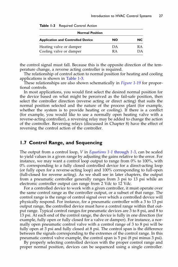
Table 1-3 Required Control Action
Normal Position
Application and Controlled Device NO NC
Heating valve or damper DA RACooling valve or damper RA DA
27Introduction to HVAC Control Systems
the control signal must fall. Because this is the opposite direction of the tem-perature change, a reverse acting controller is required.The relationship of control action to normal position for heating and cooling
applications is shown in Table 1-3.These relationships are also shown schematically in Figure 1-19 for propor-
tional controls.In most applications, you would first select the desired normal position for
the device based on what might be perceived as the fail-safe position, thenselect the controller direction (reverse acting or direct acting) that suits thenormal position selected and the nature of the process plant (for example,whether the system is to provide heating or cooling). If there is a conflict(for example, you would like to use a normally open heating valve with areverse-acting controller), a reversing relay may be added to change the actionof the controller. Reversing relays (discussed in Chapter 8) have the effect ofreversing the control action of the controller.
1.7 Control Range, and Sequencing
The output from a control loop, V in Equations 1-1 through 1-3, can be scaledto yield values in a given range by adjusting the gains relative to the error. Forinstance, we may want a control loop output to range from 0% to 100%, with0% corresponding to a fully closed controlled device for a direct-acting loop(or fully open for a reverse-acting loop) and 100% corresponding to full-open(full-closed for reverse acting). As we shall see in later chapters, the outputfrom a pneumatic controller generally ranges from 3 psi to 13 psi while anelectronic controller output can range from 2 Vdc to 12 Vdc.For a controlled device to work with a given controller, it must operate over
the same control range as the controller output, or a subset of that range. Thecontrol range is the range of control signal over which a controlled device willphysically respond. For instance, for a pneumatic controller with a 3 to 13 psioutput range, the controlled device must have a control range within that out-put range. Typical control ranges for pneumatic devices are 3 to 8 psi, and 8 to13 psi. At each end of the control range, the device is fully in one direction (forexample, fully open or fully closed for a valve or damper). For instance, a nor-mally open pneumatic control valve with a control range of 3 to 8 psi will befully open at 3 psi and fully closed at 8 psi. The control span is the differencebetween the signals corresponding to the extremes of the control range. In thispneumatic control valve example, the control span is 5 psi (8 psi minus 3 psi).By properly selecting controlled devices with the proper control range and
proper normal position, devices can be sequenced using a single controller.

28 Fundamentals of HVAC Control Systems
Sequencing means that one device is taken from one extreme of its controlrange to the other before doing the same with the next device.
Energy codes typically require that the valves have a control range that isnon-overlapping. In this case, we would select the heating valve to have a con-trol range of 0% to 50%, and a cooling valve to operate from 50% to 100%. Thiswould cause the heating valve to go from full open to full closed when thecontroller output goes from 0% to 50%, then from 50% to 100%, the chilledwater valve to go from full closed to full open. The ASHRAE Standard 90.1-2004 requirement is even more stringent than just not overlapping:
6.4.3.1.2 Dead Band. Where used to control both heating and cooling, zonethermostatic control shall be capable of providing a temperature rangeor dead band of at least 5�F within which the supply of heating andcooling energy to the zone is shut off or reduced to a minimum.
To provide this 5�F requirement one would normally use a different strategywhich will be covered later in the course.
For instance, suppose we wish to sequence a heating and cooling valve tocontrol supply air temperature using a direct-acting controller with an outputthat ranges from 0% to 100% (see Figure 1-20).
The normal position of the chilled water valve must be opposite that of the hotwater valve. This will cause one to open as the other closes using the same controlsignal. In this case, because the controller is direct-acting, the hotwater valvemustbe normally openwhile the cooling coil valvemust be normally closed. If, for anyreason,wealsowanted the coolingvalve to be normally open aswell,we coulddoso provided we also add a reversing relay between the controller and the valve.But this adds to cost and complication, and generally should be avoided if possi-ble. Another way to accomplish this is with an electronic actuator which has aswitch that allows the actuator to drive clockwise or counterclockwise as the con-trol signal increases depending on the position of the switch.
1.8 Controls Documentation, Maintenance, and Operations
All control systems should be documented with written sequences, parts lists,data sheets, damper and valve schedules, control drawings, marked site planlocations for all controls and remote devices, and points lists where applicable.This documentation must be kept in a safe and accessible place for the life ofthe systems and building. After the installation is complete, total documentedperformance testing and commissioning, clean up and fire caulking of all pene-trations should be made. Training sessions should be set up for all affectedparties to participate in. All control systems require periodic maintenance,adjustments, calibration checks, and testing in order to stay in operation prop-erly. Most often, this should be performed on a quarterly or semi-annual basisat minimum. Some standards have specific maintenance requirements such asASHRAE Standard 62.1-2004 requirement that outdoor air dampers and actua-tors to be visually inspected or remotely monitored every 3 months. Records ofall repairs and maintenance should be kept. You should refer to ASHRAE Stan-dard 180 (to be published) for further details on this subject.
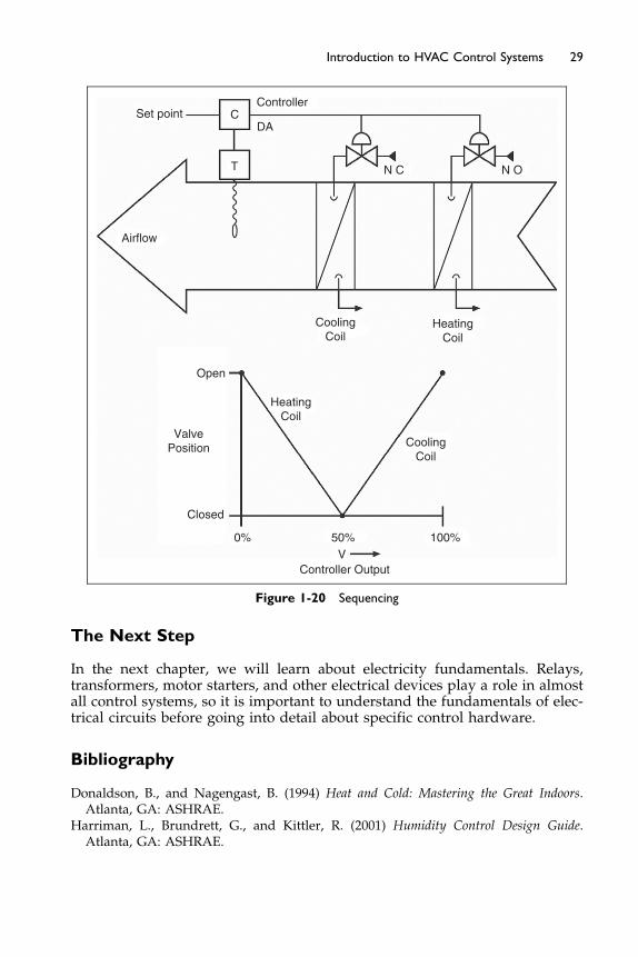
CoolingCoil
CoolingCoil
Controller Output
50%V
100%0%
Closed
ValvePosition
Airflow
T N C N O
DACSet point
Controller
Open
HeatingCoil
HeatingCoil
Figure 1-20 Sequencing
29Introduction to HVAC Control Systems
The Next Step
In the next chapter, we will learn about electricity fundamentals. Relays,transformers, motor starters, and other electrical devices play a role in almostall control systems, so it is important to understand the fundamentals of elec-trical circuits before going into detail about specific control hardware.
Bibliography
Donaldson, B., and Nagengast, B. (1994) Heat and Cold: Mastering the Great Indoors.Atlanta, GA: ASHRAE.
Harriman, L., Brundrett, G., and Kittler, R. (2001) Humidity Control Design Guide.Atlanta, GA: ASHRAE.
Chapter 2
Basics of Electricity
Contents of Chapter 2
Study Objectives of Chapter 22.1 Simple Circuits and Ohm’s Law
2.2 AC Circuits 2.3 Transformers and Power Services 2.4 Relays 2.5 Motor and Motor Starters 2.6 Variable Speed Drives 2.7 Relay Logic and Ladder Diagrams The Next StepStudy Objectives of Chapter 2
This chapter introduces simple electrical circuits and common devices usedto provide and control electrical power in HVAC systems. It is not intendedto be a comprehensive course in electrical engineering, nor does it addresselectronics. (An understanding of electronics is important if the internaloperation of analog electronic controllers and microprocessors is to beunderstood, but generally it is not necessary for most control applications.)This chapter is included because virtually all HVAC control systems willhave relays, transformers, starters, and other electrical devices as a part ofthem. Many control systems are composed almost entirely of relays, so it isimportant to understand relay logic and how to read ladder diagrams ofelectrical devices.
After studying this chapter, you should be able to:
Understand basic electricity concepts and simple electrical circuits.Understand the mathematical relationships between power, voltage,
current, and resistance.Understand how a relay works, why relays are used, and the symbols used
to show normally open and normally closed contacts.Understand how transformers work and why they are used in power
services and control systems.Understand what motor starters are and where they are used.
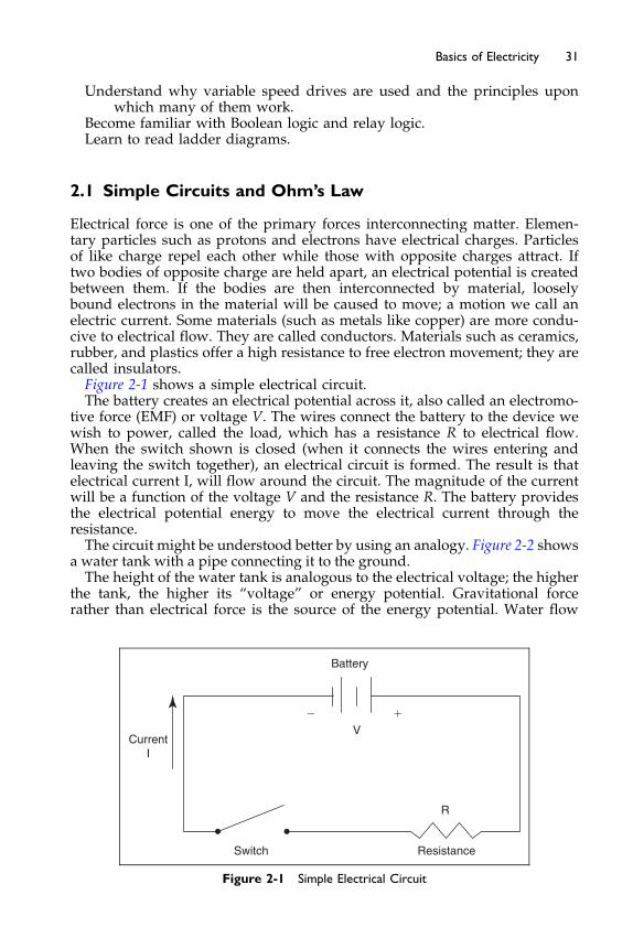
31Basics of Electricity
Understand why variable speed drives are used and the principles uponwhich many of them work.
Become familiar with Boolean logic and relay logic.Learn to read ladder diagrams.
2.1 Simple Circuits and Ohm’s Law
Electrical force is one of the primary forces interconnecting matter. Elemen-tary particles such as protons and electrons have electrical charges. Particlesof like charge repel each other while those with opposite charges attract. Iftwo bodies of opposite charge are held apart, an electrical potential is createdbetween them. If the bodies are then interconnected by material, looselybound electrons in the material will be caused to move; a motion we call anelectric current. Some materials (such as metals like copper) are more condu-cive to electrical flow. They are called conductors. Materials such as ceramics,rubber, and plastics offer a high resistance to free electron movement; they arecalled insulators.Figure 2-1 shows a simple electrical circuit.The battery creates an electrical potential across it, also called an electromo-
tive force (EMF) or voltage V. The wires connect the battery to the device wewish to power, called the load, which has a resistance R to electrical flow.When the switch shown is closed (when it connects the wires entering andleaving the switch together), an electrical circuit is formed. The result is thatelectrical current I, will flow around the circuit. The magnitude of the currentwill be a function of the voltage V and the resistance R. The battery providesthe electrical potential energy to move the electrical current through theresistance.The circuit might be understood better by using an analogy. Figure 2-2 shows
a water tank with a pipe connecting it to the ground.The height of the water tank is analogous to the electrical voltage; the higher
the tank, the higher its “voltage” or energy potential. Gravitational forcerather than electrical force is the source of the energy potential. Water flow
V��
Battery
R
ResistanceSwitch
CurrentI
Figure 2-1 Simple Electrical Circuit

Valve
Water
Tank
Height
Figure 2-2 Water Tank Analogy
32 Fundamentals of HVAC Control Systems
is analogous to electrical current and the shut-off valve is analogous to theswitch. When the valve is closed, no water flows. When the valve is opened,water will flow through the pipe down to the ground due to the force of grav-ity. The rate of water flow (the “current”) is a function of the height of the tank(the “voltage”) and the frictional resistance to flow in the pipe, analogous tothe resistance to electricity flow in our electrical circuit.
In this analogy we close the valve increasing the resistance to stop the flowof water while we open the switch increasing the resistance to stop the flow ofelectricity. We will come across the same process when dealing with waterand pneumatic control air valves and switches in the following chapters. Justremember that an open electrical switch allows no current to flow while aclosed hydronic or pneumatic valve allows no fluid to pass.
The mathematical relationship relating the current, voltage, and resistanceis expressed as:
V ¼ I � R ðEquation 2-1Þ
where V is the voltage (in volts), I is the current (in amperes, or amps forshort), and R is the resistance (in ohms, abbreviated O). This is called Ohm’slaw, named after George S. Ohm who was the first to express the relationshipin 1826. Sometimes the letter E or e is used to represent the electrical potentialinstead of V. Others use E to represent electrical potential across a battery, anduse V to represent voltage drop across a load. In this text, V is used for bothpurposes, which is common in general engineering practice.
For a practical example, often used in the field, if you wanted to convert a0–20 mA signal to be 0–10 VDC, then you would put a 500 ohm resistor acrossthe circuit, hence the new voltage would equal the 0.02 A times the 500 ohmswhich is 10 VDC.
You can imagine that if you added another pipe from the tank to the groundin our water tank example, you would still get the same flow rate through thefirst pipe no matter whether the valve through the second was opened orclosed (see Figure 2-3).
This is called parallel flow because the two pipes are in parallel with eachother (side by side). The same is true with electricity. The electrical potential
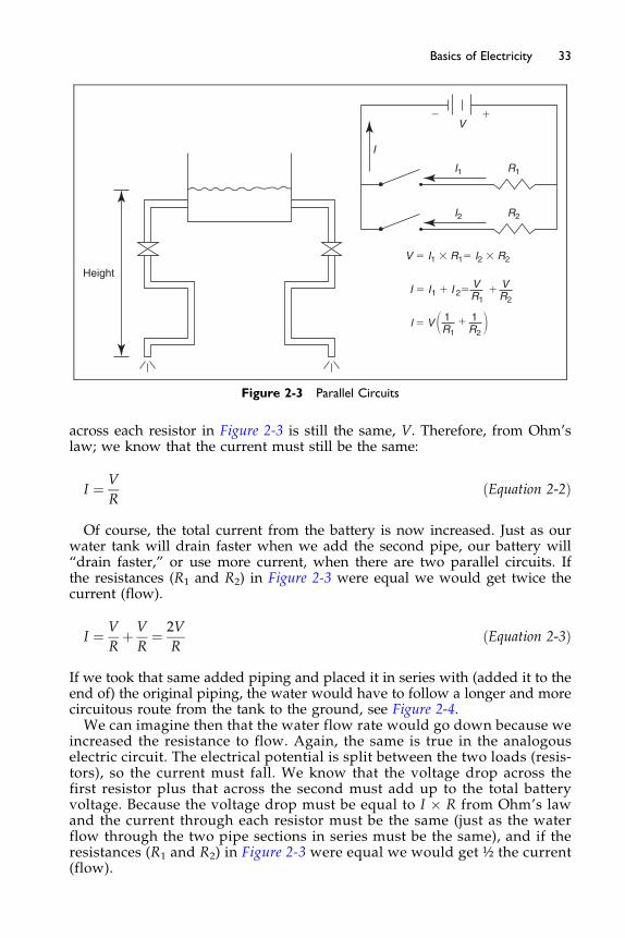
V��
R1
I
R2I2
I1
V � I1 � R1� I2 � R2
R1 R2
1 1l � V � � �
Height
R1 R2
V VI � I1 � I 2� �
Figure 2-3 Parallel Circuits
33Basics of Electricity
across each resistor in Figure 2-3 is still the same, V. Therefore, from Ohm’slaw; we know that the current must still be the same:
I ¼ V
RðEquation 2-2Þ
Of course, the total current from the battery is now increased. Just as ourwater tank will drain faster when we add the second pipe, our battery will“drain faster,” or use more current, when there are two parallel circuits. Ifthe resistances (R1 and R2) in Figure 2-3 were equal we would get twice thecurrent (flow).
I ¼ V
Rþ V
R¼ 2V
RðEquation 2-3Þ
If we took that same added piping and placed it in series with (added it to theend of) the original piping, the water would have to follow a longer and morecircuitous route from the tank to the ground, see Figure 2-4.We can imagine then that the water flow rate would go down because we
increased the resistance to flow. Again, the same is true in the analogouselectric circuit. The electrical potential is split between the two loads (resis-tors), so the current must fall. We know that the voltage drop across thefirst resistor plus that across the second must add up to the total batteryvoltage. Because the voltage drop must be equal to I � R from Ohm’s lawand the current through each resistor must be the same (just as the waterflow through the two pipe sections in series must be the same), and if theresistances (R1 and R2) in Figure 2-3 were equal we would get ½ the current(flow).
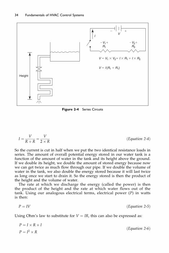
V��
�V2�R2
�V1�R1
I
V � V1 � V2� I � R1 � I � R2
Height
V � I (R1 � R1)
Figure 2-4 Series Circuits
34 Fundamentals of HVAC Control Systems
I ¼ V
Rþ R¼ V
2� RðEquation 2-4Þ
So the current is cut in half when we put the two identical resistance loads inseries. The amount of overall potential energy stored in our water tank is afunction of the amount of water in the tank and its height above the ground.If we double its height, we double the amount of stored energy because nowwe can get twice as much flow through our pipe. If we double the volume ofwater in the tank, we also double the energy stored because it will last twiceas long once we start to drain it. So the energy stored is then the product ofthe height and the volume of water.
The rate at which we discharge the energy (called the power) is thenthe product of the height and the rate at which water flows out of thetank. Using our analogous electrical terms, electrical power (P) in wattsis then:
P ¼ IV ðEquation 2-5Þ
Using Ohm’s law to substitute for V ¼ IR, this can also be expressed as:
P ¼ I � R� I
P ¼ I2 � RðEquation 2-6Þ

35Basics of Electricity
2.2 AC Circuits
In the previous section, we looked at a simple circuit using a battery maintain-ing a constant electrical potential or voltage that resulted in a constant currentthrough the circuit. This is referred to as a direct current (dc) circuit becausethe current is constant and flows only in one direction. But the electrical sys-tems serving our homes and buildings are not dc systems. Rather, they arealternating current (ac) systems.Alternating current is produced by varying the electrical potential (the volt-
age) in a sinusoidal fashion, as shown in Figure 2-5. The voltage varies frompositive (þV) to negative (�V). In the simple circuit shown in Figure 2-6, thealternating voltage causes a corresponding alternating current that swingsback and forth in the same sinusoidal fashion as the voltage. When you mea-sure the ac voltage you measure the “root mean square,” rms voltage whichfor a pure sine wave is 0.707 times the peak voltage.The time it takes for the oscillation to go through a full cycle (from peak to
peak) is called the cycle time, measured in cycles per second or Hertz (Hz).Common ac power sources in the United States are 60 Hz, while those inmany other countries are 50 Hz.Ohm’s law and the formula for power derived for dc circuits in the previ-
ous section also apply to the simple ac circuit shown in Figure 2-6. However,
Figure 2-6 Simple AC Circuit
Figure 2-5 Alternating Voltage

36 Fundamentals of HVAC Control Systems
ac circuits are never so simple in real applications. The rms current in an accircuit with resistance is given by the rms voltage divided by the resistance(“root mean square voltage” means the effective average voltage). Two otherelements – capacitance and inductance – come into play, which make ac circuitsmore complicated.
In the circuit shown in Figure 2-7, we have a capacitor in series with a resistor.A capacitor, as its symbol implies, is two parallel plates typically separated by anon-conducting material called a dielectric. If we applied a dc (constant) volt-age across the capacitor by closing the switch, the current would start as itwould if the capacitor was not in the circuit, as electrons begin to move dueto the electrical potential from the battery. However, as electrons collect onthe plates of the capacitor, they begin to repel other electrons and the flowdiminishes. This is shown in the graph on the right of Figure 2-7.
Quickly, the current would drop to near zero, actually a very low amountcalled leakage due to the very low but still non-zero conductivity of the dielec-tric. At this point, energy is stored in the capacitor, and is fully charged. Thecapacitor can be thought of as a storage device. We measure its size using theterm capacitance (C), which is a function of the size of the plates, their separa-tion distance, and the properties of the dielectric.
As Figure 2-7 indicates, a capacitor is like an open switch in a dc circuitonce steady-state is reached, which is why it does not play a part in most dcsystems. But when a capacitor is placed in an ac circuit, the result is verydifferent. The alternating voltage simply allows the capacitor to charge, thendischarge, then charge again. While no electrons actually pass through thecapacitor, there is still current flow back and forth through the load just as itwould if the capacitor was not there.
The only difference is that the capacitor causes a time delay in the current. Ittakes time to charge and discharge the capacitor plate, so current and the volt-age become out of phase, as shown in Figure 2-8. Another effect that has animpact on ac circuit current flow is inductance, which is a resistance to currentchange caused by magnetic induction. As current flows through a wire, a mag-netic field is created around it, as shown in Figure 2-9 (with current directionalarrows shown as the direction electrons follow, flowing from positive tonegative).
If we wound the wire into a spiral, the magnetic fields from the wireswould align inside the spiral, creating a strong magnetic field in the center.
Figure 2-7 Capacitor in DC Circuit
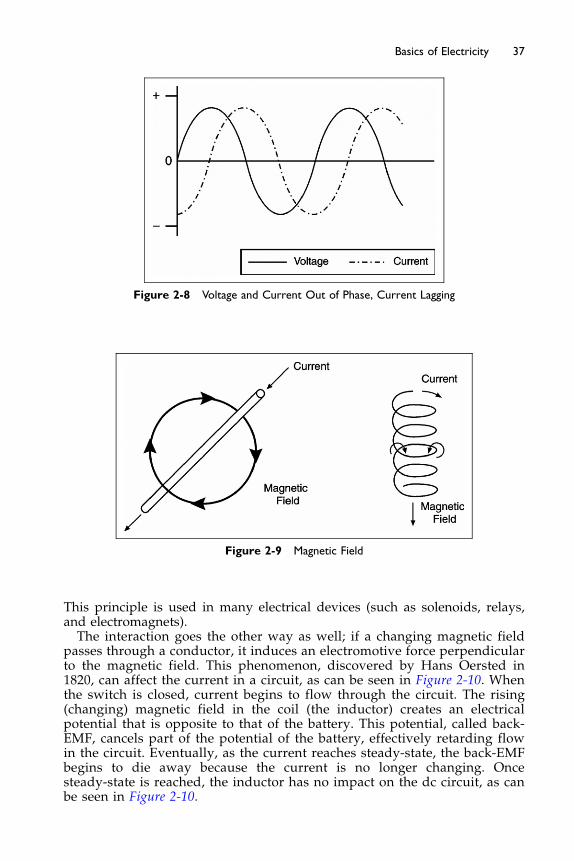
Figure 2-9 Magnetic Field
Figure 2-8 Voltage and Current Out of Phase, Current Lagging
37Basics of Electricity
This principle is used in many electrical devices (such as solenoids, relays,and electromagnets).The interaction goes the other way as well; if a changing magnetic field
passes through a conductor, it induces an electromotive force perpendicularto the magnetic field. This phenomenon, discovered by Hans Oersted in1820, can affect the current in a circuit, as can be seen in Figure 2-10. Whenthe switch is closed, current begins to flow through the circuit. The rising(changing) magnetic field in the coil (the inductor) creates an electricalpotential that is opposite to that of the battery. This potential, called back-EMF, cancels part of the potential of the battery, effectively retarding flowin the circuit. Eventually, as the current reaches steady-state, the back-EMFbegins to die away because the current is no longer changing. Oncesteady-state is reached, the inductor has no impact on the dc circuit, as canbe seen in Figure 2-10.
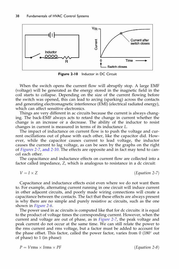
Figure 2-10 Inductor in DC Circuit
38 Fundamentals of HVAC Control Systems
When the switch opens the current flow will abruptly stop. A large EMF(voltage) will be generated as the energy stored in the magnetic field in thecoil starts to collapse. Depending on the size of the current flowing beforethe switch was opened, this can lead to arcing (sparking) across the contactsand generating electromagnetic interference (EMI) (electrical radiated energy),which can affect sensitive electronics.
Things are very different in ac circuits because the current is always chang-ing. The back-EMF always acts to retard the change in current whether thechange is an increase or a decrease. The ability of the inductor to resistchanges in current is measured in terms of its inductance L.
The impact of inductance on current flow is to push the voltage and cur-rent oscillations out of phase with each other, like the capacitor did. How-ever, while the capacitor causes current to lead voltage, the inductorcauses the current to lag voltage, as can be seen by the graphs on the rightof Figures 2-7, and 2-10. The effects are opposite and in fact may tend to can-cel each other.
The capacitance and inductance effects on current flow are collected into afactor called impedance, Z, which is analogous to resistance in a dc circuit:
V ¼ I � Z ðEquation 2-7Þ
Capacitance and inductance effects exist even where we do not want themto. For example, alternating current running in one circuit will induce currentin other adjacent circuits, and poorly made wiring connections will create acapacitance between the contacts. The fact that these effects are always presentis why there are no simple and purely resistive ac circuits, such as the oneshown in Figure 2-6.
The power used in ac circuits is computed like that for dc circuits: it is equalto the product of voltage times the corresponding current. However, when thecurrent and voltage are out of phase, as in Figure 2-7, the peak voltage andpeak current do not occur at the same time. We can still relate the power tothe rms current and rms voltage, but a factor must be added to account forthe phase offset. This factor, called the power factor, varies from 0 (180� outof phase) to 1 (in phase):
P ¼ Vrms� Irms� PF ðEquation 2-8Þ

Figure 2-11 Three-phase Voltage
39Basics of Electricity
Because power plants, transmission lines, transformers, and other distribu-tion equipment have to be sized for the maximum current, utilities oftenimpose an added charge to users that have very low power factors. A lowpower factor is typically caused by an inductive device such as a motor. Capa-citors, which as noted above have an opposite effect on current/voltage phaseshifts as inductors, can be used to correct power factor in these instances.Most larger buildings are served by three-phase power services (discussed
in the next section), typically with four wires, three of which are hot andone that is neutral (grounded at the service entrance or distribution trans-former). The three hot wires have ac voltages that are 120� out of phase witheach other, as shown in Figure 2-11. Three phase (abbreviated to 3Ø) power isused because it is convenient for motors (it causes a naturally rotating fieldthat starts a motor turning in the right direction) and it reduces the amountof current required for the same amount of power. The power equation fora three-phase circuit is:
P ¼ Vrms� IrmsPF�ffiffiffi3
pðEquation 2-9Þ
2.3 Transformers and Power Services
A power transformer is a device that is used primarily to convert one ac volt-age to another. Based on the principle that alternating current in an inductorelectro-magnetically induces an electrical potential in adjacent conductors,transformers can interconnect two circuits without any electrical connectionbetween them. A transformer is shown schematically in Figure 2-12. It is essen-tially composed of coiled wiring (inductors) in each circuit which is connectedby an electromagnetic field. Current flow in the primary circuit induces a volt-age across the secondary coil.If the number of coils in the primary circuit differs from the secondary, then
the induced voltage will differ from the primary. The secondary voltage willbe higher or lower by the ratio of the number of turns in each system. Forinstance, if there are four times as many windings on the primary side ofthe transformer as there are on the secondary, the voltage on the secondary
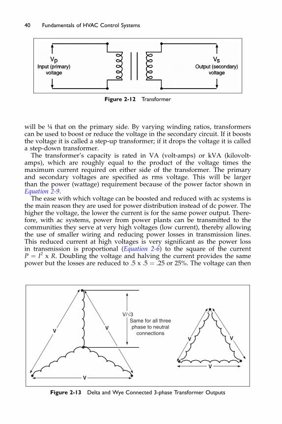
Figure 2-12 Transformer
40 Fundamentals of HVAC Control Systems
will be ¼ that on the primary side. By varying winding ratios, transformerscan be used to boost or reduce the voltage in the secondary circuit. If it booststhe voltage it is called a step-up transformer; if it drops the voltage it is calleda step-down transformer.
The transformer’s capacity is rated in VA (volt-amps) or kVA (kilovolt-amps), which are roughly equal to the product of the voltage times themaximum current required on either side of the transformer. The primaryand secondary voltages are specified as rms voltage. This will be largerthan the power (wattage) requirement because of the power factor shown inEquation 2-9.
The ease with which voltage can be boosted and reduced with ac systems isthe main reason they are used for power distribution instead of dc power. Thehigher the voltage, the lower the current is for the same power output. There-fore, with ac systems, power from power plants can be transmitted to thecommunities they serve at very high voltages (low current), thereby allowingthe use of smaller wiring and reducing power losses in transmission lines.This reduced current at high voltages is very significant as the power lossin transmission is proportional (Equation 2-6) to the square of the currentP ¼ I2 x R. Doubling the voltage and halving the current provides the samepower but the losses are reduced to .5 x .5 ¼ .25 or 25%. The voltage can then
VV
V
V/√3Same for all threephase to neutral
connectionsVV
V
Figure 2-13 Delta and Wye Connected 3-phase Transformer Outputs

41Basics of Electricity
be reduced using a transformer at the building service entrance to a lower,safer voltage to power lights and motors, and all the other power consumingdevices in the building.Three-phase transformers have three secondary, or output, windings. These
windings may be connected in two ways – Delta or Wye. In the Delta connec-tion the ends of the three windings are connected together and the same volt-age is available across each phase. In the Wye connection the three phasesare all connected at one end: a common point. This point, called common orneutral, is usually grounded. The Wye connection provides a phase-to-phasevoltage and a phase-to-common 1/√3 times the phase-to-phase voltage.The typical commercial building is provided (downstream of the utility
transformer) with either a 208 V, 230 V, 480 V (or other), three-phase, four-wire service from which various voltages can be obtained depending onwhich wires are used. The voltages available with two of these service typesare shown in Figure 2-14. When there is a 480 V service, there typically willbe one or more transformers in the building that step down the voltage to120 V, which is the voltage used by most common household and officeplug-in appliances in North America.The lowest voltage available with typical services is still higher than that
needed for typical control systems. Control systems use very little power, sothe cost advantages offered by higher voltages (lower current, smaller wiresizes) are negligible. Therefore, control systems typically are powered byanother step-down transformer producing 24 V. This is sufficiently low that
120/208 V Service
480/277 V Service
Figure 2-14 Four-wire Wye Connected Transformer Outputs

42 Fundamentals of HVAC Control Systems
most building codes do not require many of the expensive protection devices(such as conduit and junction boxes) that are required for higher voltage cir-cuits. This reduces installation costs. Typically, control transformers are small(less than 75 VA), which places them in a lower cost electrical code category(NEC Class 2, which includes power systems rated at less than 30 volts and100 VA).
2.4 Relays
A relay is an electrical switch that opens and closes under control of anotherelectrical circuit. The electromagnetic relay with one or more set of contactswas invented by Joseph Henry in 1835. There are many types of relays usedin controls, which will be discussed in later chapters. In simple electrical cir-cuits, the term refers to a device that delivers an on/off control signal. In asense, the relay is a type of remote-controlled switch.
Figure 2-15 shows a type of electromagnetic relay. It works by taking advan-tage of the magnetic force that results from current flow. Wire is woundaround an iron core. When current is allowed to pass through the wire ineither direction (when a voltage is placed across leads labeled A and B inthe diagram), a magnetic field is formed in the iron. Iron is highly permeableto magnetic fields; much like copper is highly conductive to current flow. Theresult is that an electromagnet is created. The magnet attracts the metal arma-ture (sometimes called a clapper), which is allowed to move toward the mag-net, causing the contacts to close (connect to each other), connecting leadslabeled C and D in the schematic. The contacts are often called “dry” contactsbecause they are electrically isolated from other circuits, including the circuitthat energizes the relay, and hence they have no source of voltage in and ofthemselves. The relay solenoid coil is represented as a circle while the relaycontact is represented in wiring diagrams by two parallel lines.
Figure 2-16 shows two simple circuits with a relay interconnecting the two.When the manual switch in the first circuit is closed, the relay is energized,
Figure 2-15 Electromagnetic Relay
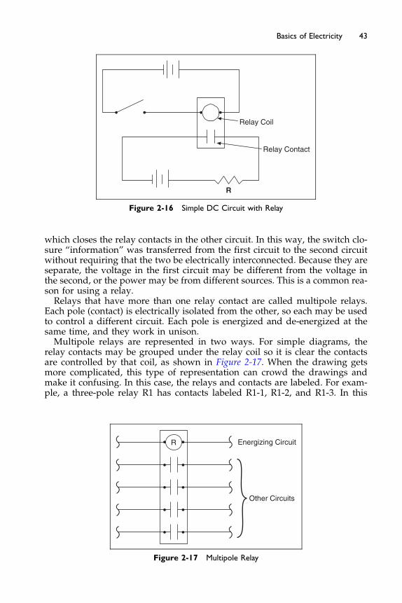
Relay Coil
Relay Contact
R
Figure 2-16 Simple DC Circuit with Relay
43Basics of Electricity
which closes the relay contacts in the other circuit. In this way, the switch clo-sure “information” was transferred from the first circuit to the second circuitwithout requiring that the two be electrically interconnected. Because they areseparate, the voltage in the first circuit may be different from the voltage inthe second, or the power may be from different sources. This is a common rea-son for using a relay.Relays that have more than one relay contact are called multipole relays.
Each pole (contact) is electrically isolated from the other, so each may be usedto control a different circuit. Each pole is energized and de-energized at thesame time, and they work in unison.Multipole relays are represented in two ways. For simple diagrams, the
relay contacts may be grouped under the relay coil so it is clear the contactsare controlled by that coil, as shown in Figure 2-17. When the drawing getsmore complicated, this type of representation can crowd the drawings andmake it confusing. In this case, the relays and contacts are labeled. For exam-ple, a three-pole relay R1 has contacts labeled R1-1, R1-2, and R1-3. In this
Energizing CircuitR
Other Circuits
Figure 2-17 Multipole Relay

44 Fundamentals of HVAC Control Systems
way, the contacts may appear anywhere in the diagram without having toshow wires running back to the relay.
In Chapter 1, when speaking of controlled devices such as valves anddampers, the term normal position referred to the state of the device whencontrol power was removed. For a general purpose relay, the normal posi-tion refers to the state of the contact when the relay is not energized. Thus,a normally open contact, N.O., is open when the relay is not energized (nocurrent is allowed to flow through it) and closes when the relay is ener-gized. Normally open contacts are shown in Figures 2-15, 2-16, and 2-17.A normally closed contact, N.C., (represented diagrammatically as a con-tact with a slash through it) operates in an opposite manner to the normallyopen contact; it is closed when the relay is not energized and opens whenthe relay is energized. Normally open and normally closed contacts areshown in Figure 2-18.
Relay contacts may be single-throw or double-throw. A single-throw con-tact is much like a two-way control valve controlling a fluid, while the dou-ble-throw contact is much like a three-way valve. Figure 2-18 shows bothtypes of contacts used in simple circuits to turn on pilot lights. The contacton the double-throw relay has a common terminal that is simultaneouslyswitched to the normally open terminal when the relay is energized and tothe normally closed terminal when the relay is de-energized.
In Figure 2-18, when the manual switch is closed, the relay is energized,causing all the normally open contacts to close and all the normally closedcontacts to open, turning on the red (R) pilot lights and turning off the green(G) pilot lights. When the switch is open, the relay is de-energized, closing thenormally closed contacts and opening the normally open contacts, turning onthe green pilot lights and turning off the red pilot lights.
Relays are commonly used as control logic devices; and they are discussedmore in Chapter 4.
Double throw
G
G
R
R
Single throw, normally closed
Single throw, normally open
Figure 2-18 Single- and Double-throw Contacts
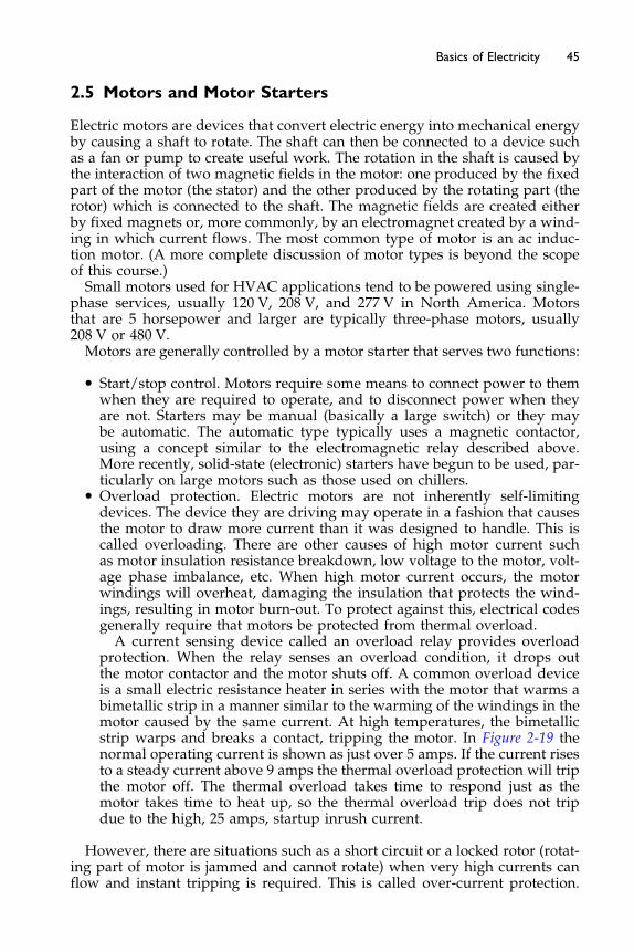
45Basics of Electricity
2.5 Motors and Motor Starters
Electric motors are devices that convert electric energy into mechanical energyby causing a shaft to rotate. The shaft can then be connected to a device suchas a fan or pump to create useful work. The rotation in the shaft is caused bythe interaction of two magnetic fields in the motor: one produced by the fixedpart of the motor (the stator) and the other produced by the rotating part (therotor) which is connected to the shaft. The magnetic fields are created eitherby fixed magnets or, more commonly, by an electromagnet created by a wind-ing in which current flows. The most common type of motor is an ac induc-tion motor. (A more complete discussion of motor types is beyond the scopeof this course.)Small motors used for HVAC applications tend to be powered using single-
phase services, usually 120 V, 208 V, and 277 V in North America. Motorsthat are 5 horsepower and larger are typically three-phase motors, usually208 V or 480 V.Motors are generally controlled by a motor starter that serves two functions:
� Start/stop control. Motors require some means to connect power to themwhen they are required to operate, and to disconnect power when theyare not. Starters may be manual (basically a large switch) or they maybe automatic. The automatic type typically uses a magnetic contactor,using a concept similar to the electromagnetic relay described above.More recently, solid-state (electronic) starters have begun to be used, par-ticularly on large motors such as those used on chillers.
� Overload protection. Electric motors are not inherently self-limitingdevices. The device they are driving may operate in a fashion that causesthe motor to draw more current than it was designed to handle. This iscalled overloading. There are other causes of high motor current suchas motor insulation resistance breakdown, low voltage to the motor, volt-age phase imbalance, etc. When high motor current occurs, the motorwindings will overheat, damaging the insulation that protects the wind-ings, resulting in motor burn-out. To protect against this, electrical codesgenerally require that motors be protected from thermal overload.
A current sensing device called an overload relay provides overloadprotection. When the relay senses an overload condition, it drops outthe motor contactor and the motor shuts off. A common overload deviceis a small electric resistance heater in series with the motor that warms abimetallic strip in a manner similar to the warming of the windings in themotor caused by the same current. At high temperatures, the bimetallicstrip warps and breaks a contact, tripping the motor. In Figure 2-19 thenormal operating current is shown as just over 5 amps. If the current risesto a steady current above 9 amps the thermal overload protection will tripthe motor off. The thermal overload takes time to respond just as themotor takes time to heat up, so the thermal overload trip does not tripdue to the high, 25 amps, startup inrush current.
However, there are situations such as a short circuit or a locked rotor (rotat-ing part of motor is jammed and cannot rotate) when very high currents canflow and instant tripping is required. This is called over-current protection.
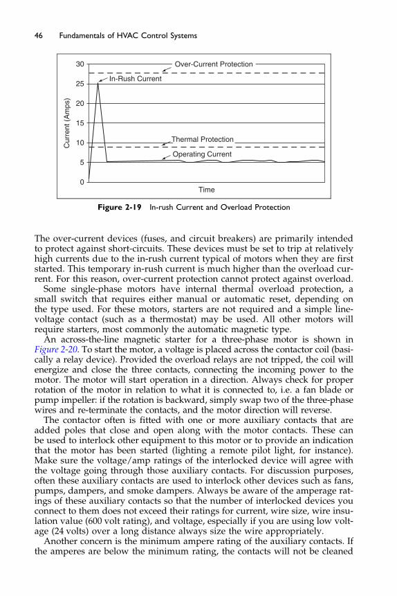
In-Rush Current
30
25
20
15
10
5
0
Operating Current
Time
Cur
rent
(A
mps
)Over-Current Protection
Thermal Protection
Figure 2-19 In-rush Current and Overload Protection
46 Fundamentals of HVAC Control Systems
The over-current devices (fuses, and circuit breakers) are primarily intendedto protect against short-circuits. These devices must be set to trip at relativelyhigh currents due to the in-rush current typical of motors when they are firststarted. This temporary in-rush current is much higher than the overload cur-rent. For this reason, over-current protection cannot protect against overload.
Some single-phase motors have internal thermal overload protection, asmall switch that requires either manual or automatic reset, depending onthe type used. For these motors, starters are not required and a simple line-voltage contact (such as a thermostat) may be used. All other motors willrequire starters, most commonly the automatic magnetic type.
An across-the-line magnetic starter for a three-phase motor is shown inFigure 2-20. To start the motor, a voltage is placed across the contactor coil (basi-cally a relay device). Provided the overload relays are not tripped, the coil willenergize and close the three contacts, connecting the incoming power to themotor. The motor will start operation in a direction. Always check for properrotation of the motor in relation to what it is connected to, i.e. a fan blade orpump impeller: if the rotation is backward, simply swap two of the three-phasewires and re-terminate the contacts, and the motor direction will reverse.
The contactor often is fitted with one or more auxiliary contacts that areadded poles that close and open along with the motor contacts. These canbe used to interlock other equipment to this motor or to provide an indicationthat the motor has been started (lighting a remote pilot light, for instance).Make sure the voltage/amp ratings of the interlocked device will agree withthe voltage going through those auxiliary contacts. For discussion purposes,often these auxiliary contacts are used to interlock other devices such as fans,pumps, dampers, and smoke dampers. Always be aware of the amperage rat-ings of these auxiliary contacts so that the number of interlocked devices youconnect to them does not exceed their ratings for current, wire size, wire insu-lation value (600 volt rating), and voltage, especially if you are using low volt-age (24 volts) over a long distance always size the wire appropriately.
Another concern is the minimum ampere rating of the auxiliary contacts. Ifthe amperes are below the minimum rating, the contacts will not be cleaned
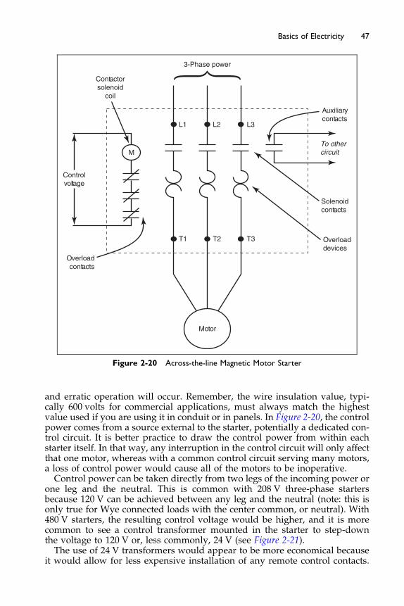
Contactorsolenoid
coil
Controlvoltage
Overloadcontacts
3-Phase power
M
Motor
L1 L2 L3
T1 T2 T3 Overloaddevices
Solenoidcontacts
Auxiliarycontacts
To othercircuit
Figure 2-20 Across-the-line Magnetic Motor Starter
47Basics of Electricity
and erratic operation will occur. Remember, the wire insulation value, typi-cally 600 volts for commercial applications, must always match the highestvalue used if you are using it in conduit or in panels. In Figure 2-20, the controlpower comes from a source external to the starter, potentially a dedicated con-trol circuit. It is better practice to draw the control power from within eachstarter itself. In that way, any interruption in the control circuit will only affectthat one motor, whereas with a common control circuit serving many motors,a loss of control power would cause all of the motors to be inoperative.Control power can be taken directly from two legs of the incoming power or
one leg and the neutral. This is common with 208 V three-phase startersbecause 120 V can be achieved between any leg and the neutral (note: this isonly true for Wye connected loads with the center common, or neutral). With480 V starters, the resulting control voltage would be higher, and it is morecommon to see a control transformer mounted in the starter to step-downthe voltage to 120 V or, less commonly, 24 V (see Figure 2-21).The use of 24 V transformers would appear to be more economical because
it would allow for less expensive installation of any remote control contacts.
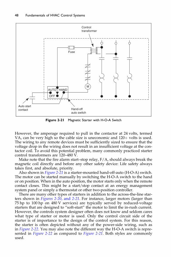
AUTO
Fuse
OFF
HAND
Hand-offauto switch
Controltransformer
Auto startcontact
M
Figure 2-21 Magnetic Starter with H-O-A Switch
48 Fundamentals of HVAC Control Systems
However, the amperage required to pull in the contactor at 24 volts, termedVA, can be very high so the cable size is uneconomic and 120þ volts is used.The wiring to any remote devices must be sufficiently sized to ensure that thevoltage drop in the wiring does not result in an insufficient voltage at the con-tactor coil. To avoid this potential problem, many commonly practiced startercontrol transformers are 120–480 V.
Make note that the fire alarm start–stop relay, F/A, should always break themagnetic coil directly and before any other safety device: Life safety alwaystakes first, and absolute, priority.
Also shown in Figure 2-21 is a starter-mounted hand-off-auto (H-O-A) switch.The motor can be started manually by switching the H-O-A switch to the handor on position. When in the auto position, the motor starts only when the remotecontact closes. This might be a start/stop contact at an energy managementsystem panel or simply a thermostat or other two-position controller.
There are many other types of starters in addition to the across-the-line star-ters shown in Figures 2-20, and 2-21. For instance, larger motors (larger than75 hp to 100 hp on 480 V services) are typically served by reduced-voltagestarters that are designed to “soft-start” the motor to limit the in-rush current.However, the controls system designer often does not know and seldom careswhat type of starter or motor is used. Only the control circuit side of thestarter is of importance to the design of the control system. For this reason,the starter is often depicted without any of the power-side wiring, such asin Figure 2-22. You may also note the different way the H-O-A switch is repre-sented in Figure 2-22 as compared to Figure 2-21. Both styles are commonlyused.
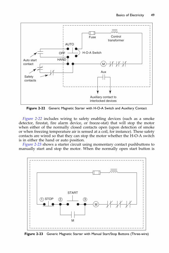
AUTO
Fuse
OFF
HAND
Controltransformer
Auto startcontact M
Safetycontacts
Aux
Auxiliary contact tointerlocked devices
H-O-A Switch
Figure 2-22 Generic Magnetic Starter with H-O-A Switch and Auxiliary Contact
49Basics of Electricity
Figure 2-22 includes wiring to safety enabling devices (such as a smokedetector, firestat, fire alarm device, or freeze-stat) that will stop the motorwhen either of the normally closed contacts open (upon detection of smokeor when freezing temperature air is sensed at a coil, for instance). These safetycontacts are wired so that they can stop the motor whether the H-O-A switchis in either the hand or auto position.Figure 2-23 shows a starter circuit using momentary contact pushbuttons to
manually start and stop the motor. When the normally open start button is
STOP
START
M
M
2 31
Figure 2-23 Generic Magnetic Starter with Manual Start/Stop Buttons (Three-wire)
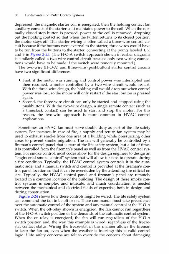
50 Fundamentals of HVAC Control Systems
depressed, the magnetic starter coil is energized, then the holding contact (anauxiliary contact of the starter coil) maintains power to the coil. When the nor-mally closed stop button is pressed, power to the coil is removed, droppingout the holding contact so that when the button returns to its closed position,the motor stays off. This starter wiring is often called a three-wire control cir-cuit because if the buttons were external to the starter, three wires would haveto be run from the buttons to the starter, connecting at the points labeled 1, 2,and 3 in Figure 2-23. (The H-O-A switch approach shown in earlier diagramsis similarly called a two-wire control circuit because only two wiring connec-tions would have to be made if the switch were remotely mounted.)
The two-wire (H-O-A) and three-wire (pushbutton) starter control circuitshave two significant differences:
� First, if the motor was running and control power was interrupted andthen resumed, a motor controlled by a two-wire circuit would restart.With the three-wire design, the holding coil would drop out when controlpower was lost, so the motor will only restart if the start button is pressedagain.
� Second, the three-wire circuit can only be started and stopped using thepushbuttons. With the two-wire design, a single remote contact (such asa timeclock contact) can be used to start and stop the motor. For thisreason, the two-wire approach is more common in HVAC controlapplications.
Sometimes an HVAC fan must serve double duty as part of the life safetysystem. For instance, in case of fire, a supply and return fan system may beused to exhaust smoke from one area of a building while pressurizing otherareas to prevent smoke migration. The fan will generally be controlled by afireman’s control panel that is part of the life safety system, but a lot of timesit is controlled from the fireman’s panel as well as from the HVAC control sys-tem. For smoke control, most codes allow for the design engineer to design an“engineered smoke control” system that will allow for fans to operate duringa fire condition. Typically, the HVAC control system controls it in the auto-matic side, and a manual switch and control is provided at the fireman’s con-trol panel location so that it can be overridden by the attending fire official onsite. Typically, the HVAC control panel and fireman’s panel are remotelylocated in a common location of the building. The design of these smoke con-trol systems is complex and intricate, and much coordination is neededbetween the mechanical and electrical fields of expertise, both in design andduring construction.
Figure 2-24 shows how these controls might be wired. The life safety systemcan command the fan to be off or on. These commands must take precedenceover the automatic control of the system and any manual control at the H-O-Aswitch. When the off-relay shown is energized, the fan cannot run regardlessof the H-O-A switch position or the demands of the automatic control system.When the on-relay is energized, the fan will run regardless of the H-O-Aswitch position and, the way this example is wired, regardless of the freeze-stat contact status. Wiring the freeze-stat in this manner allows the firemanto keep the fan on, even when the weather is freezing; this is valid controllogic if life safety concerns are felt to override the concern about damaging
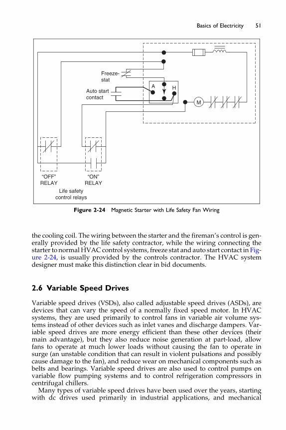
M
“OFF”RELAY
“ON”RELAY
A
Freeze-stat
Auto startcontact
H
Life safetycontrol relays
Figure 2-24 Magnetic Starter with Life Safety Fan Wiring
51Basics of Electricity
the cooling coil. The wiring between the starter and the fireman’s control is gen-erally provided by the life safety contractor, while the wiring connecting thestarter to normalHVAC control systems, freeze stat and auto start contact in Fig-ure 2-24, is usually provided by the controls contractor. The HVAC systemdesigner must make this distinction clear in bid documents.
2.6 Variable Speed Drives
Variable speed drives (VSDs), also called adjustable speed drives (ASDs), aredevices that can vary the speed of a normally fixed speed motor. In HVACsystems, they are used primarily to control fans in variable air volume sys-tems instead of other devices such as inlet vanes and discharge dampers. Var-iable speed drives are more energy efficient than these other devices (theirmain advantage), but they also reduce noise generation at part-load, allowfans to operate at much lower loads without causing the fan to operate insurge (an unstable condition that can result in violent pulsations and possiblycause damage to the fan), and reduce wear on mechanical components such asbelts and bearings. Variable speed drives are also used to control pumps onvariable flow pumping systems and to control refrigeration compressors incentrifugal chillers.Many types of variable speed drives have been used over the years, starting
with dc drives used primarily in industrial applications, and mechanical
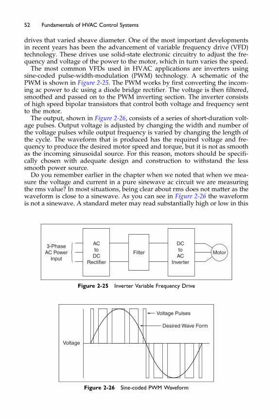
52 Fundamentals of HVAC Control Systems
drives that varied sheave diameter. One of the most important developmentsin recent years has been the advancement of variable frequency drive (VFD)technology. These drives use solid-state electronic circuitry to adjust the fre-quency and voltage of the power to the motor, which in turn varies the speed.
The most common VFDs used in HVAC applications are inverters usingsine-coded pulse-width-modulation (PWM) technology. A schematic of thePWM is shown in Figure 2-25. The PWM works by first converting the incom-ing ac power to dc using a diode bridge rectifier. The voltage is then filtered,smoothed and passed on to the PWM inverting section. The inverter consistsof high speed bipolar transistors that control both voltage and frequency sentto the motor.
The output, shown in Figure 2-26, consists of a series of short-duration volt-age pulses. Output voltage is adjusted by changing the width and number ofthe voltage pulses while output frequency is varied by changing the length ofthe cycle. The waveform that is produced has the required voltage and fre-quency to produce the desired motor speed and torque, but it is not as smoothas the incoming sinusoidal source. For this reason, motors should be specifi-cally chosen with adequate design and construction to withstand the lesssmooth power source.
Do you remember earlier in the chapter when we noted that when we mea-sure the voltage and current in a pure sinewave ac circuit we are measuringthe rms value? In most situations, being clear about rms does not matter as thewaveform is close to a sinewave. As you can see in Figure 2-26 the waveformis not a sinewave. A standard meter may read substantially high or low in this
Voltage
Voltage Pulses
Desired Wave Form
Figure 2-26 Sine-coded PWM Waveform
3-PhaseAC Power
Input
ACto
DCRectifier
DCtoAC
Inverter
Filter Motor
Figure 2-25 Inverter Variable Frequency Drive
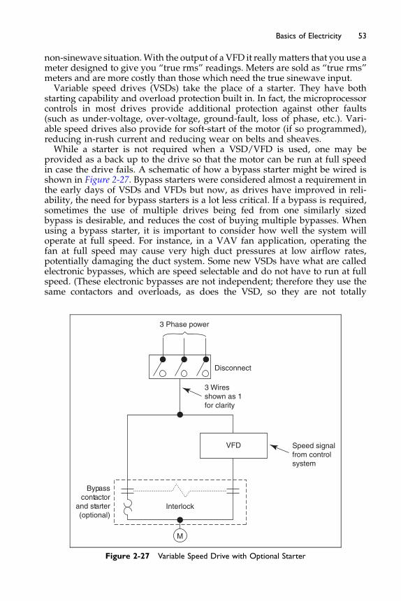
53Basics of Electricity
non-sinewave situation.With the output of a VFD it reallymatters that you use ameter designed to give you “true rms” readings. Meters are sold as “true rms”meters and are more costly than those which need the true sinewave input.Variable speed drives (VSDs) take the place of a starter. They have both
starting capability and overload protection built in. In fact, the microprocessorcontrols in most drives provide additional protection against other faults(such as under-voltage, over-voltage, ground-fault, loss of phase, etc.). Vari-able speed drives also provide for soft-start of the motor (if so programmed),reducing in-rush current and reducing wear on belts and sheaves.While a starter is not required when a VSD/VFD is used, one may be
provided as a back up to the drive so that the motor can be run at full speedin case the drive fails. A schematic of how a bypass starter might be wired isshown in Figure 2-27. Bypass starters were considered almost a requirement inthe early days of VSDs and VFDs but now, as drives have improved in reli-ability, the need for bypass starters is a lot less critical. If a bypass is required,sometimes the use of multiple drives being fed from one similarly sizedbypass is desirable, and reduces the cost of buying multiple bypasses. Whenusing a bypass starter, it is important to consider how well the system willoperate at full speed. For instance, in a VAV fan application, operating thefan at full speed may cause very high duct pressures at low airflow rates,potentially damaging the duct system. Some new VSDs have what are calledelectronic bypasses, which are speed selectable and do not have to run at fullspeed. (These electronic bypasses are not independent; therefore they use thesame contactors and overloads, as does the VSD, so they are not totally
M
3 Phase power
Disconnect
VFD Speed signalfrom controlsystem
3 Wiresshown as 1for clarity
Interlock
Bypasscontactor
and starter(optional)
Figure 2-27 Variable Speed Drive with Optional Starter
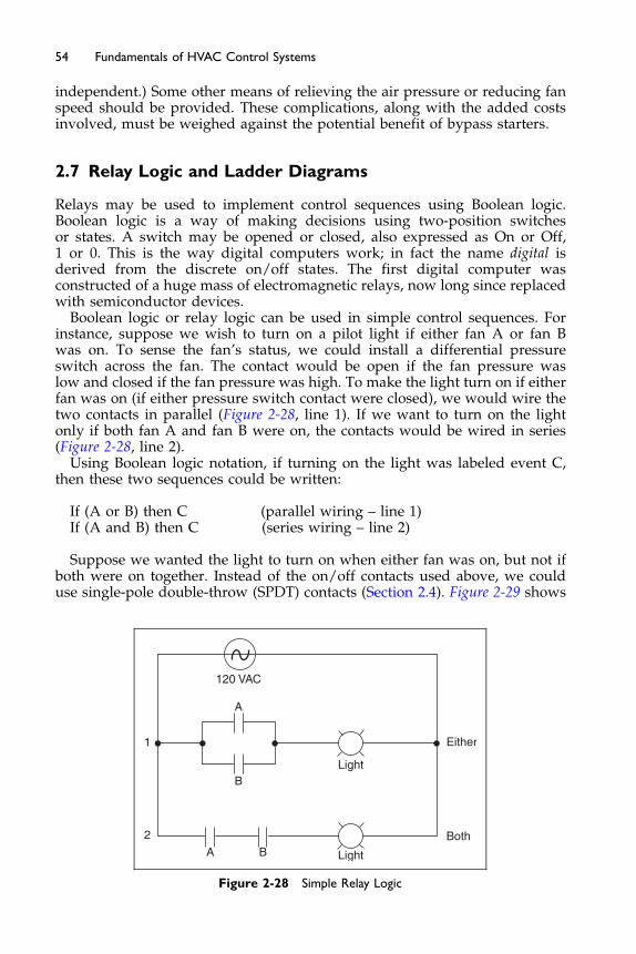
54 Fundamentals of HVAC Control Systems
independent.) Some other means of relieving the air pressure or reducing fanspeed should be provided. These complications, along with the added costsinvolved, must be weighed against the potential benefit of bypass starters.
2.7 Relay Logic and Ladder Diagrams
Relays may be used to implement control sequences using Boolean logic.Boolean logic is a way of making decisions using two-position switchesor states. A switch may be opened or closed, also expressed as On or Off,1 or 0. This is the way digital computers work; in fact the name digital isderived from the discrete on/off states. The first digital computer wasconstructed of a huge mass of electromagnetic relays, now long since replacedwith semiconductor devices.
Boolean logic or relay logic can be used in simple control sequences. Forinstance, suppose we wish to turn on a pilot light if either fan A or fan Bwas on. To sense the fan’s status, we could install a differential pressureswitch across the fan. The contact would be open if the fan pressure waslow and closed if the fan pressure was high. To make the light turn on if eitherfan was on (if either pressure switch contact were closed), we would wire thetwo contacts in parallel (Figure 2-28, line 1). If we want to turn on the lightonly if both fan A and fan B were on, the contacts would be wired in series(Figure 2-28, line 2).
Using Boolean logic notation, if turning on the light was labeled event C,then these two sequences could be written:
If (A or B) then C (parallel wiring – line 1)If (A and B) then C (series wiring – line 2)
Suppose we wanted the light to turn on when either fan was on, but not ifboth were on together. Instead of the on/off contacts used above, we coulduse single-pole double-throw (SPDT) contacts (Section 2.4). Figure 2-29 shows
1
2
A B
BLight
Either
Both
Light
A
120 VAC
Figure 2-28 Simple Relay Logic
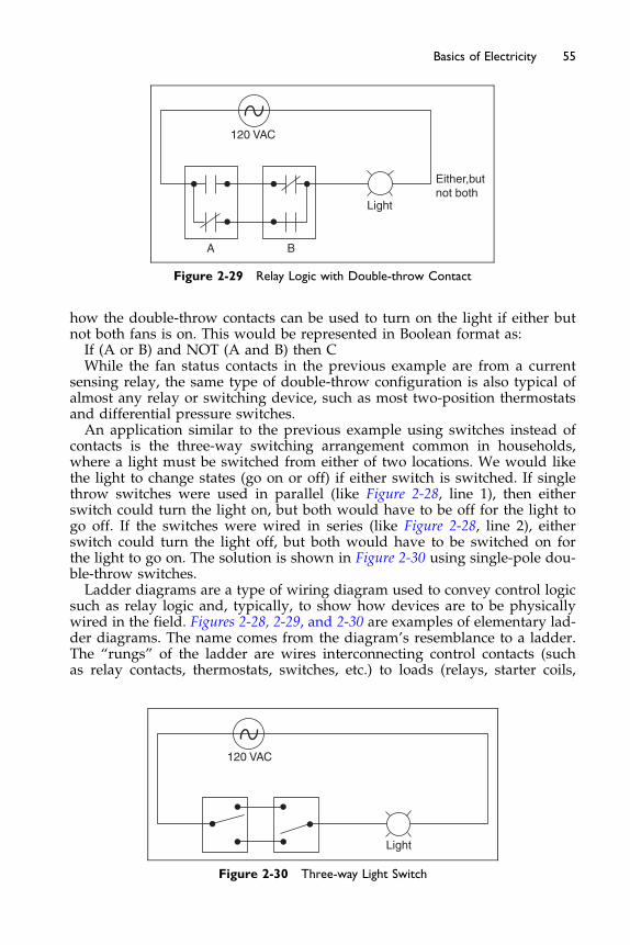
Either,butnot both
Light
BA
120 VAC
Figure 2-29 Relay Logic with Double-throw Contact
55Basics of Electricity
how the double-throw contacts can be used to turn on the light if either butnot both fans is on. This would be represented in Boolean format as:If (A or B) and NOT (A and B) then CWhile the fan status contacts in the previous example are from a current
sensing relay, the same type of double-throw configuration is also typical ofalmost any relay or switching device, such as most two-position thermostatsand differential pressure switches.An application similar to the previous example using switches instead of
contacts is the three-way switching arrangement common in households,where a light must be switched from either of two locations. We would likethe light to change states (go on or off) if either switch is switched. If singlethrow switches were used in parallel (like Figure 2-28, line 1), then eitherswitch could turn the light on, but both would have to be off for the light togo off. If the switches were wired in series (like Figure 2-28, line 2), eitherswitch could turn the light off, but both would have to be switched on forthe light to go on. The solution is shown in Figure 2-30 using single-pole dou-ble-throw switches.Ladder diagrams are a type of wiring diagram used to convey control logic
such as relay logic and, typically, to show how devices are to be physicallywired in the field. Figures 2-28, 2-29, and 2-30 are examples of elementary lad-der diagrams. The name comes from the diagram’s resemblance to a ladder.The “rungs” of the ladder are wires interconnecting control contacts (suchas relay contacts, thermostats, switches, etc.) to loads (relays, starter coils,
Light
120 VAC
Figure 2-30 Three-way Light Switch

56 Fundamentals of HVAC Control Systems
etc.) across the control power voltage potential represented by the two verticallines on the left and right.
Figure 2-31 shows many of the symbols used in ladder diagrams to representcommonly used HVAC devices. Many of these devices have already been intro-duced. One group which has not been introduced is the time delay relay. Oftenequipment needs to operate in sequence or to have a delay before action is taken.
DC Battery− + TR Time Delay Relay (Coil)
NC, Instant open, Time close
NO, Instant open, Time close
NC, Instant close, Time open
NO, Instant close, Time open
NO Contacts
DPST Switchor Contacts
DPDT Switchor Contacts
Limit Switches
Fuse
Circuit Breaker
Transformer
Time Delay Relay
Motor (or Motorized Actuator)
TR
NC
NO
F
NC Contacts
Swtich
Swtich
Relay
Relay
AC Power Source
Closes onpressure rise
Opens onpressure rise
Closes on“flow”
Opens on“flow”
Closes ontemperature rise
Opens ontemperature rise
EP
K
M1
Electric-Pneumatic Relay(interface to pneumaticcontrols)
Control Relay Solenoid(also designated “CR”)
Magnetic MotorStarter Coil
Pilot Light(color indicated in circle)
Alarm Horn
3-PositionRotary Switch
3-Position Switch(alternate style)
Push Buttons(momentary contact)
AUTO
AUTO
OFF
OFF
ON
ON
NO
NC
Figure 2-31 Symbols for Electrical Logic Devices
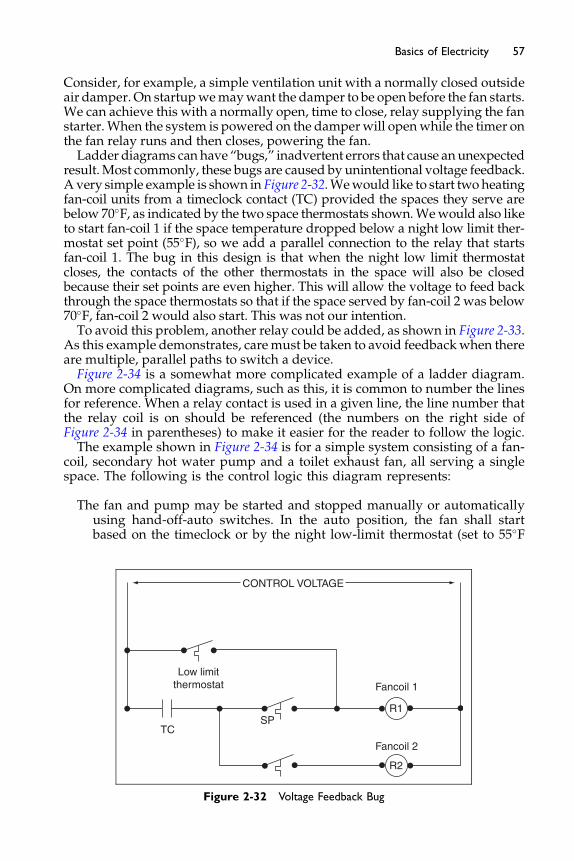
57Basics of Electricity
Consider, for example, a simple ventilation unit with a normally closed outsideair damper. On startupwemaywant the damper to be open before the fan starts.We can achieve this with a normally open, time to close, relay supplying the fanstarter.When the system is powered on the damperwill openwhile the timer onthe fan relay runs and then closes, powering the fan.Ladder diagrams canhave “bugs,” inadvertent errors that cause anunexpected
result.Most commonly, these bugs are caused by unintentional voltage feedback.A very simple example is shown in Figure 2-32.Wewould like to start two heatingfan-coil units from a timeclock contact (TC) provided the spaces they serve arebelow 70�F, as indicated by the two space thermostats shown.Wewould also liketo start fan-coil 1 if the space temperature dropped below a night low limit ther-mostat set point (55�F), so we add a parallel connection to the relay that startsfan-coil 1. The bug in this design is that when the night low limit thermostatcloses, the contacts of the other thermostats in the space will also be closedbecause their set points are even higher. This will allow the voltage to feed backthrough the space thermostats so that if the space served by fan-coil 2 was below70�F, fan-coil 2 would also start. This was not our intention.To avoid this problem, another relay could be added, as shown in Figure 2-33.
As this example demonstrates, caremust be taken to avoid feedbackwhen thereare multiple, parallel paths to switch a device.Figure 2-34 is a somewhat more complicated example of a ladder diagram.
On more complicated diagrams, such as this, it is common to number the linesfor reference. When a relay contact is used in a given line, the line number thatthe relay coil is on should be referenced (the numbers on the right side ofFigure 2-34 in parentheses) to make it easier for the reader to follow the logic.The example shown in Figure 2-34 is for a simple system consisting of a fan-
coil, secondary hot water pump and a toilet exhaust fan, all serving a singlespace. The following is the control logic this diagram represents:
The fan and pump may be started and stopped manually or automaticallyusing hand-off-auto switches. In the auto position, the fan shall startbased on the timeclock or by the night low-limit thermostat (set to 55�F
CONTROL VOLTAGE
Low limitthermostat
TCSP
R1
R2
Fancoil 1
Fancoil 2
Figure 2-32 Voltage Feedback Bug
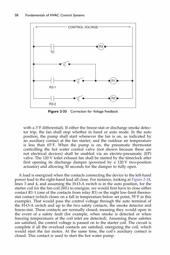
CONTROL VOLTAGE
R3
TC
R3-1
R1
R2
R3-2
Figure 2-33 Correction for Voltage Feedback
58 Fundamentals of HVAC Control Systems
with a 3�F differential). If either the freeze-stat or discharge smoke detec-tor trip, the fan shall stop whether in hand or auto mode. In the autoposition, the pump shall start whenever the fan is on, as indicated byan auxiliary contact at the fan starter, and the outdoor air temperatureis less than 65�F. When the pump is on, the pneumatic thermostatcontrolling the hot water control valve (not shown because these arenot electrical devices) shall be enabled via an electric-pneumatic (EP)valve. The 120 V toilet exhaust fan shall be started by the timeclock afterfirst opening its discharge damper (powered by a 120 V two-positionactuator) and allowing 30 seconds for the damper to fully open.
A load is energized when the contacts connecting the device to the left-handpower lead to the right-hand lead all close. For instance, looking at Figure 2-34,lines 3 and 4, and assuming the H-O-A switch is in the auto position, for thestarter coil for the fan-coil (M1) to energize, we would first have to close eithercontact R1-1 (one of the contacts from relay R1) or the night low-limit thermo-stat contact (which closes on a fall in temperature below set point, 55�F in thisexample). That would pass the control voltage through the auto terminal ofthe H-O-A switch and up to the two safety contacts, the smoke detector andfreeze-stat. These contacts are normally closed; meaning they would open inthe event of a safety fault (for example, when smoke is detected or whenfreezing temperatures at the coil inlet are detected). Assuming these safetiesare satisfied, the control voltage is passed on to the starter coil. The circuit iscomplete if all the overload contacts are satisfied, energizing the coil, whichwould start the fan motor. At the same time, the coil’s auxiliary contact isclosed. This contact is used to start the hot water pump.
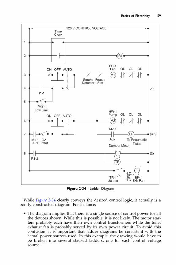
120 V CONTROL VOLTAGETimeClock
1
2
3
4
5
6
7
8
R1-2
M1-1Aux
NightLow Limit
R1-1
ON OFF AUTO
SmokeDetector
FreezeStat
FC-1Fan
M1
Aux
Damper Motor
To PneumaticT’stat
(3,6)
(2)
M2-1
EP
TR
TR-130 sec
N.O.IOTC
EF-1Exh Fan
OL
R1
OL OL
(2)
HW-1Pump OL OL OLON OFF AUTO
OAT’stat
M2
Figure 2-34 Ladder Diagram
59Basics of Electricity
While Figure 2-34 clearly conveys the desired control logic, it actually is apoorly constructed diagram. For instance:
� The diagram implies that there is a single source of control power for allthe devices shown. While this is possible, it is not likely. The motor star-ters probably each have their own control transformers while the toiletexhaust fan is probably served by its own power circuit. To avoid thisconfusion, it is important that ladder diagrams be consistent with theactual power sources used. In this example, the drawing would have tobe broken into several stacked ladders, one for each control voltagesource.
60 Fundamentals of HVAC Control Systems
� The physical location of devices is not clear. The diagram implies thatall the devices are in the same panel. In reality, the timeclock and perhapsthe EP valve are in a control panel; the H-O-A switches, overloads, andstarter coils are in the individual motor starters; and the thermostats arein other remote locations. This problem is often avoided by labelingdevices and terminal numbers to show location.
While the ladder diagram is a convenient means of conveying control logic,it is often a poor representation of the physical layout of the system, as thisexample illustrates. In most cases, HVAC design engineers will never needto develop a ladder diagram as part of the control system description. Writtenlogic sequences and system schematics, along with coordination details andspecifications, are usually sufficient to satisfactorily convey the design intentand division of responsibility to the bidding contractors. Where there maybe confusion in some wiring responsibility, a detail such as that shown inFigure 2-24 should be added to the plans, but a ladder diagram seldomis required.
Ladder diagrams are probably most commonly used with factory installedcontrols associated with packaged air conditioners and chillers. However,even in this application, they are becoming obsolete as control system designsmigrate towards digital controls. With digital controls (as we will learn inChapters 10, 11, and 12), much of the control logic is implemented in software,thereby obviating the need for many of the relays and controllers found inelectric control systems.
The Next Step
In the next chapter, we will learn about control valves and control dampers,two of the most common controlled devices used in HVAC systems. Theproper selection and sizing of control valves and dampers are critical to theperformance of the control system. As these devices have very specificoperating characteristics we can often choose the control methodology to bestsuit these characteristics.

Chapter 3
Control Valves and Dampers
Contents of Chapter 3
IntroductionStudy Objectives of Chapter 33.1 Two-way Control Valves
3.2 Three-way Control Valves 3.3 Selecting and Sizing Valves 3.4 Control Dampers 3.5 Selecting and Sizing Dampers The Next StepBibliographyIntroduction
When you have finished this chapter you should have a good conceptualunderstanding of how controls work. Although we will be providing youwith some information about calculations, the issues of sizing and how flowsvary under different circumstances may not be clear to you. This is becausevalve choice and sizing is not a simple process for anyone. In the real worldmany designers rely on controls specialists (consultants and manufacturers)to choose and size the valves and dampers for their systems. Although thevalve choice may be done by someone else, you should understand theoptions for design and the basic terminology that these specialists will use.
Study Objectives of Chapter 3
Control valves and control dampers are the two primary means to control theflow of water and air in HVAC systems. This chapter explains how thesedevices work and how they are selected and sized.After studying this chapter, you should:
Be familiar with the valve types that are available and which are mostappropriate for flow control in various applications.
Understand the operation of mixing valves and diverting valves.
62 Fundamentals of HVAC Control Systems
Know how to select control valves for hydronic systems.Understand the difference between parallel blade and opposed blade dam-
pers and where each is used.Understand how damper design affects leakage, and where leakage mini-
mization is important.Understand how mixing dampers can be selected and positioned to encour-
age mixing.Know how to size mixing and volume control dampers.
3.1 Two-way Control Valves
The control valve is possibly the most important component of a fluid distribu-tion system because it regulates the flow of fluid to the process under control.In HVAC systems, control valves are primarily used to control the flow ofchilled water, hot water and condenser water, the subject of this section. Con-trol of other fluids including steam, refrigerants, gasses, and oil, are similar inmany aspects but are not specifically addressed here because they have specificrequirements for design including issues of safety and material compatibility.
Styles and Principles of Operation
Control valves may be either two-way (one pipe in and one pipe out) whichact as a variable resistance to flow or three-way (two pipes in and one outfor mixing valves – one pipe in and two out for diverting valves) as depictedin Figure 3-1. Three-way valves may be either mixing (two flow streams aremerged into one) or diverting (a single flow stream is broken into two), asshown in the figure. With all three configurations shown, the valves modulateflow through the cooling or heating coil to vary the capacity of the coil.
With the two-way configuration, flow through the circulation system isvariable. In the three-way configurations, flow remains relatively constantthrough the loop which includes the pump and varies in the loop containingthe coil. This works well for systems in which the supply of heat, typically aboiler, or supply of cooling, typically a chiller, requires a constant flow. Inother systems it may be that constant flow in the coil is important, perhapsto prevent freezing, In this case the pump can be in the coil loop.
Control valves typically come in three valve styles: globe, butterfly, andball. The globe-type valve has been the most common for many years, butthe characterized ball valves are becoming very popular and are starting tobecome a significant part of the working marketplace. Below 2-inch size, theyhave usually sweat (soldered) or screwed connections, while above 2 inchthey are typically flanged.
Figure 3-2 shows a typical globe-type two-way single-seated control valve. Itconsists of a body, a single seat, and a plug. The plug is connected to a stem,which, in turn, is connected to the actuator, also called the actuator or motor.Moving the stem up and down controls the flow. Full shut-off is achievedwhen the plug is firmly down against the seat.
The body is connected to the piping system in any suitable way (screwed,flanged, welded, soldered, etc.), but it is important that unions or something
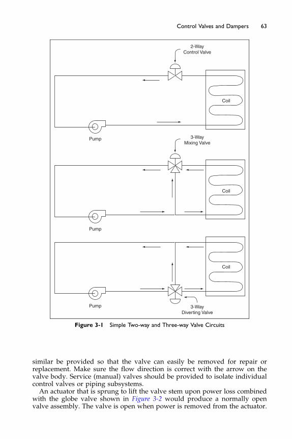
2-WayControl Valve
3-WayMixing Valve
3-WayDiverting Valve
Pump
Pump
Pump
Coil
Coil
Coil
Figure 3-1 Simple Two-way and Three-way Valve Circuits
63Control Valves and Dampers
similar be provided so that the valve can easily be removed for repair orreplacement. Make sure the flow direction is correct with the arrow on thevalve body. Service (manual) valves should be provided to isolate individualcontrol valves or piping subsystems.An actuator that is sprung to lift the valve stem upon power loss combined
with the globe valve shown in Figure 3-2 would produce a normally openvalve assembly. The valve is open when power is removed from the actuator.

Stem
Plug
Seat
Body
Packing
CompressionSpring
Linkage
Actuator
Figure 3-2 Two-way Globe Single-seated Valve (Fluid Flow is Left to Right)
64 Fundamentals of HVAC Control Systems
Figure 3-3 shows a globe valve that closes with the stem up. Using this actu-ator with the valve in Figure 3-3 would produce a normally closed valveassembly as the valve is closed when power is removed from the actuator.In both cases, the stem must be driven against the flow of fluid to close thevalve. Normally open valves are generally desired, when available, as theyalways fail to the open position, and, if closure is desired, then manual valvescan be closed down/off to restrict the flow until repairs can be made.
The figures indicate that flow through the valve must occur in the directionshown by the arrow. All control valves will have an arrow cast into the
OUT IN
Figure 3-3 Normally Closed Globe Two-way Valve

65Control Valves and Dampers
outside of the body to indicate flow direction. The reason for this is as follows:in any linkage between motor and valve stem there will be some slack, a littlefree movement of the valve stem. When flow occurs in the correct direction,the velocity pressure of the fluid and the fluid differential pressure acrossthe valve will tend to open the valve. Therefore, the motor must press tightlyto close it, taking up any free movement. If flow takes place in the wrongdirection, the velocity pressure tends to close the valve (pushing down ontop of the plug of the valve in Figure 3-2). When the valve throttles towardits closed position, the pressure may be enough to push the plug to the closedposition, taking advantage of the free movement or slack in the valve stem.When this happens, flow ceases, then the velocity pressure component disap-pears, and free movement allows the valve to crack open. Flow begins, thevelocity component reappears, and the cycle is repeated indefinitely. Eachtime the flow stops and starts, the inertial force of the fluid in the pipe causesa shock known as water hammer. Besides being noisy and annoying, it cancause failure of the piping system. Therefore, it is important never to installa control valve backward.Figure 3-4 shows a double-seated valve, also called a balanced valve. As the
name implies, it has two plugs and seats arranged so that fluid differentialpressure is balanced and the actuator does not have to fight against differen-tial pressure to close the valve, as it does in the single-seated valves shown inthe Figure 3-2. This reduces the size of the actuator. But the valve inherentlycannot provide tight shut-off. This reduces its applicability to HVAC systems,where tight shut-off is usually desired, to minimize energy costs (to preventleakage and simultaneous heating and cooling).Modulating globe-type control valves is made with two basic types of
plugs: the linear (V-port) plug (see Figure 3-5) and equal percentage plug(see Figure 3-6). Many manufacturers have variations on these two designs(called modified linear or modified equal percentage), the characteristics ofwhich are usually similar to those described here.A flat plate plug (see Figure 3-7) is sometimes used for two-position, quick-
opening duty.
IN OUT
Figure 3-4 Double-seated Two-way Globe Valve
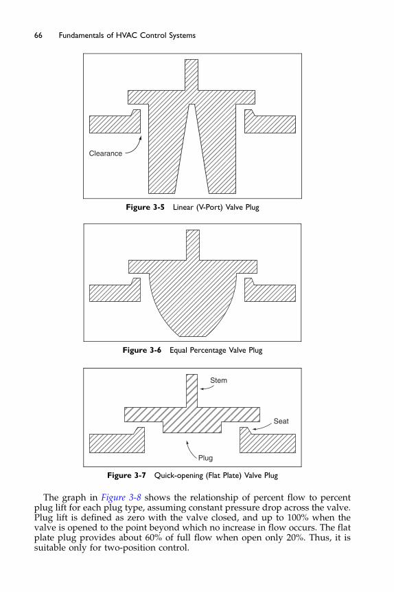
Clearance
Figure 3-5 Linear (V-Port) Valve Plug
Figure 3-6 Equal Percentage Valve Plug
Stem
Seat
Plug
Figure 3-7 Quick-opening (Flat Plate) Valve Plug
66 Fundamentals of HVAC Control Systems
The graph in Figure 3-8 shows the relationship of percent flow to percentplug lift for each plug type, assuming constant pressure drop across the valve.Plug lift is defined as zero with the valve closed, and up to 100% when thevalve is opened to the point beyond which no increase in flow occurs. The flatplate plug provides about 60% of full flow when open only 20%. Thus, it issuitable only for two-position control.

Flo
w
Y
Linear
Equal %
% Lift
Quickopen
Figure 3-8 Control Valve Characteristics
67Control Valves and Dampers
Control valve characteristics is a complex study of the what characteristicsare needed from the HVAC system and its coil, and how the valve is designedto operate and function. Correctly choosing these characteristics issues canyield a properly combined control valve for its application. A very simpleexample of this is depicted in Figure 3-9.As shown in Figure 3-10, the linear plug has an essentially linear characteristic
while the equal percentage plug is shaped so that the flow increment is an expo-nential function of the lift increment. This means that when the valve is almostclosed, a large percent change of lift is required for a small change of flow.As the plug reaches its last tiny increment of closure until it fully shuts, the
flow drops off very quickly. This minimum flow rate just before closure is afunction of the physical construction of the valve, plug, and seat. The ratioof the minimum rate to maximum rate at the same pressure drop across thevalve is called the rangeability or turn-down ratio. For a typical HVAC controlvalve, this ratio will be about 20 to 1, which is equivalent to a 5% flow whenthe valve is barely cracked open. This is usually adequate for HVAC controlwork. Valves with larger ratios are available but they are more expensive.
% H
eat T
rans
fer
% Control Output% Lift/Controller Output
% F
low
% H
eat T
rans
fer
% Flow
Figure 3-9 Combination of Coil and Control Valve Characteristics
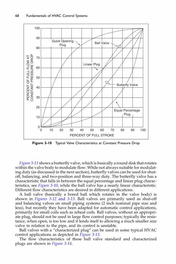
Quick OpeningPlug
Linear Plug
Equal PercentagePlug
PERCENT OF FULL STROKE
PE
RC
EN
T O
F F
ULL
FLO
W A
TC
ON
ST
AN
T P
RE
SS
UR
E D
RO
P
00
10
20
30
40
50
60
70
80
90
100
10 20 30 40 50 60 70 80 90 100
Butterfly Valve
Ball Valve
Figure 3-10 Typical Valve Characteristics at Constant Pressure Drop
68 Fundamentals of HVAC Control Systems
Figure 3-11 shows a butterfly valve,which is basically a round disk that rotateswithin the valve body to modulate flow.While not always suitable for modulat-ing duty (as discussed in the next section), butterfly valves can be used for shut-off, balancing, and two-position and three-way duty. The butterfly valve has acharacteristic that falls in between the equal percentage and linear plug charac-teristics, see Figure 3-10, while the ball valve has a nearly linear characteristic.Different flow characteristics are desired in different applications.
A ball valve (basically a bored ball which rotates in the valve body) isshown in Figures 3-12 and 3-13. Ball valves are primarily used as shut-offand balancing valves on small piping systems (2 inch nominal pipe size andless), but recently they have been adapted for automatic control applications,primarily for small coils such as reheat coils. Ball valves, without an appropri-ate plug, should not be used in large flow control purposes; typically the resis-tance, when open, is too low and it lends itself to allowing a much smaller sizevalve in relation to the pipe, and its control is unstable.
Ball valves with a “characterized plug” can be used in some typical HVACcontrol applications as depicted in Figure 3-13.
The flow characteristics of these ball valve standard and characterizedplugs are shown in Figure 3-14.

Ball
Seat ring
Body
PackingPacking gland Stem
Thrustwasher
Body endpiece
Figure 3-12 Ball Valve Layout
Insert
Figure 3-13 Characterized Ball Valve
Figure 3-11 Butterfly Valve
69Control Valves and Dampers
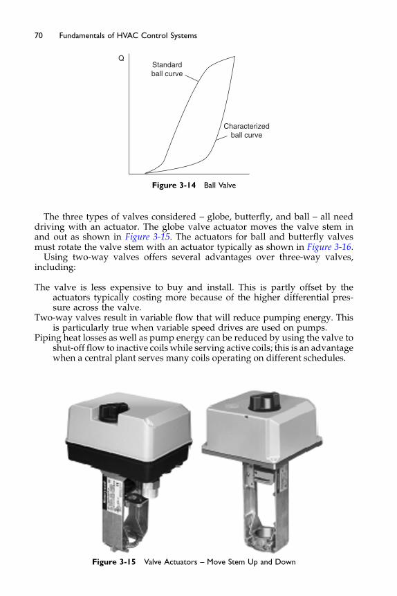
QStandardball curve
Characterizedball curve
Figure 3-14 Ball Valve
70 Fundamentals of HVAC Control Systems
The three types of valves considered – globe, butterfly, and ball – all needdriving with an actuator. The globe valve actuator moves the valve stem inand out as shown in Figure 3-15. The actuators for ball and butterfly valvesmust rotate the valve stem with an actuator typically as shown in Figure 3-16.
Using two-way valves offers several advantages over three-way valves,including:
The valve is less expensive to buy and install. This is partly offset by theactuators typically costing more because of the higher differential pres-sure across the valve.
Two-way valves result in variable flow that will reduce pumping energy. Thisis particularly true when variable speed drives are used on pumps.
Piping heat losses as well as pump energy can be reduced by using the valve toshut-off flow to inactive coils while serving active coils; this is an advantagewhen a central plant serves many coils operating on different schedules.
Figure 3-15 Valve Actuators – Move Stem Up and Down
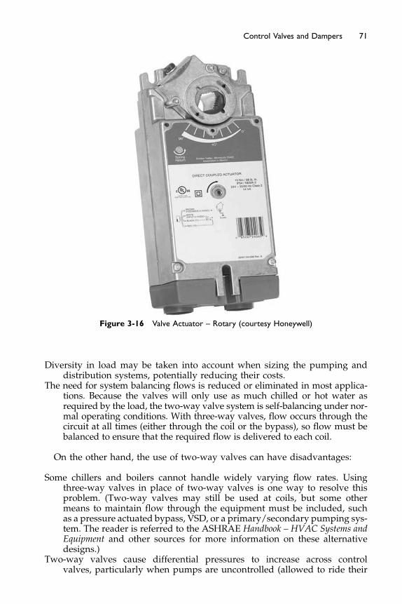
Figure 3-16 Valve Actuator – Rotary (courtesy Honeywell)
71Control Valves and Dampers
Diversity in load may be taken into account when sizing the pumping anddistribution systems, potentially reducing their costs.
The need for system balancing flows is reduced or eliminated in most applica-tions. Because the valves will only use as much chilled or hot water asrequired by the load, the two-way valve system is self-balancing under nor-mal operating conditions. With three-way valves, flow occurs through thecircuit at all times (either through the coil or the bypass), so flow must bebalanced to ensure that the required flow is delivered to each coil.
On the other hand, the use of two-way valves can have disadvantages:
Some chillers and boilers cannot handle widely varying flow rates. Usingthree-way valves in place of two-way valves is one way to resolve thisproblem. (Two-way valves may still be used at coils, but some othermeans to maintain flow through the equipment must be included, suchas a pressure actuated bypass, VSD, or a primary/secondary pumping sys-tem. The reader is referred to the ASHRAE Handbook – HVAC Systems andEquipment and other sources for more information on these alternativedesigns.)
Two-way valves cause differential pressures to increase across controlvalves, particularly when pumps are uncontrolled (allowed to ride their
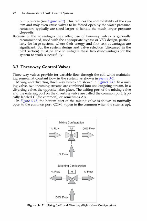
Be
72 Fundamentals of HVAC Control Systems
pump curves (see Figure 3-31). This reduces the controllability of the sys-tem and may even cause valves to be forced open by the water pressure.Actuators typically are sized larger to handle the much larger pressureclose-offs.
cause of the advantages they offer, use of two-way valves is generallyrecommended, used with the appropriate bypass or VSD design, particu-larly for large systems where their energy and first-cost advantages aresignificant. But the system design and valve selection (discussed in thenext section) must be able to mitigate these two disadvantages for thesystem to work successfully.
3.2 Three-way Control Valves
Three-way valves provide for variable flow through the coil while maintain-ing somewhat constant flow in the system, as shown in Figure 3-1.
Mixing and diverting three-way valves are shown in Figures 3-17. In a mix-ing valve, two incoming streams are combined into one outgoing stream. In adiverting valve, the opposite takes place. The exiting port of the mixing valveand the entering port on the diverting valve are called the common port, typi-cally labeled C (for common), or sometimes AB.
In Figure 3-18, the bottom port of the mixing valve is shown as normallyopen to the common port, COM., (open to the common when the stem is up).
% Flow % FlowM
100% Flow
% Flow 100% FlowM
% Flow
Diverting Configuration
Mixing Configuration
Figure 3-17 Mixing (Left) and Diverting (Right) Valve Configurations
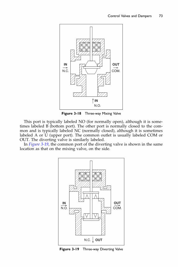
IN
N.C.
IN
N.O.
OUT
COM.
Figure 3-18 Three-way Mixing Valve
73Control Valves and Dampers
This port is typically labeled NO (for normally open), although it is some-times labeled B (bottom port). The other port is normally closed to the com-mon and is typically labeled NC (normally closed), although it is sometimeslabeled A or U (upper port). The common outlet is usually labeled COM orOUT. The diverting valve is similarly labeled.In Figure 3-19, the common port of the diverting valve is shown in the same
location as that on the mixing valve, on the side.
OUT
IN
N.O.
N.C.
OUT
COM.
Figure 3-19 Three-way Diverting Valve
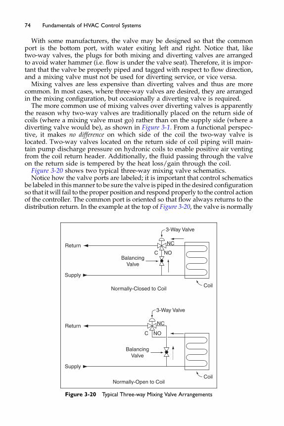
74 Fundamentals of HVAC Control Systems
With some manufacturers, the valve may be designed so that the commonport is the bottom port, with water exiting left and right. Notice that, liketwo-way valves, the plugs for both mixing and diverting valves are arrangedto avoid water hammer (i.e. flow is under the valve seat). Therefore, it is impor-tant that the valve be properly piped and tagged with respect to flow direction,and a mixing valve must not be used for diverting service, or vice versa.
Mixing valves are less expensive than diverting valves and thus are morecommon. In most cases, where three-way valves are desired, they are arrangedin the mixing configuration, but occasionally a diverting valve is required.
The more common use of mixing valves over diverting valves is apparentlythe reason why two-way valves are traditionally placed on the return side ofcoils (where a mixing valve must go) rather than on the supply side (where adiverting valve would be), as shown in Figure 3-1. From a functional perspec-tive, it makes no difference on which side of the coil the two-way valve islocated. Two-way valves located on the return side of coil piping will main-tain pump discharge pressure on hydronic coils to enable positive air ventingfrom the coil return header. Additionally, the fluid passing through the valveon the return side is tempered by the heat loss/gain through the coil.
Figure 3-20 shows two typical three-way mixing valve schematics.Notice how the valve ports are labeled; it is important that control schematics
be labeled in thismanner to be sure the valve is piped in the desired configurationso that it will fail to the proper position and respond properly to the control actionof the controller. The common port is oriented so that flow always returns to thedistribution return. In the example at the top of Figure 3-20, the valve is normally
Normally-Closed to Coil
Normally-Open to Coil
3-Way Valve
C NO
NC
Coil
Return
Supply
BalancingValve
C
NC
NO
Coil
3-Way Valve
Return
Supply
BalancingValve
Figure 3-20 Typical Three-way Mixing Valve Arrangements
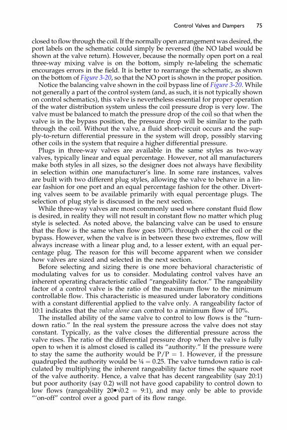
75Control Valves and Dampers
closed to flow through the coil. If the normally open arrangementwasdesired, theport labels on the schematic could simply be reversed (the NO label would beshown at the valve return). However, because the normally open port on a realthree-way mixing valve is on the bottom, simply re-labeling the schematicencourages errors in the field. It is better to rearrange the schematic, as shownon the bottom of Figure 3-20, so that the NO port is shown in the proper position.Notice the balancing valve shown in the coil bypass line of Figure 3-20. While
not generally a part of the control system (and, as such, it is not typically shownon control schematics), this valve is nevertheless essential for proper operationof the water distribution system unless the coil pressure drop is very low. Thevalve must be balanced to match the pressure drop of the coil so that when thevalve is in the bypass position, the pressure drop will be similar to the paththrough the coil. Without the valve, a fluid short-circuit occurs and the sup-ply-to-return differential pressure in the system will drop, possibly starvingother coils in the system that require a higher differential pressure.Plugs in three-way valves are available in the same styles as two-way
valves, typically linear and equal percentage. However, not all manufacturersmake both styles in all sizes, so the designer does not always have flexibilityin selection within one manufacturer’s line. In some rare instances, valvesare built with two different plug styles, allowing the valve to behave in a lin-ear fashion for one port and an equal percentage fashion for the other. Divert-ing valves seem to be available primarily with equal percentage plugs. Theselection of plug style is discussed in the next section.While three-way valves are most commonly used where constant fluid flow
is desired, in reality they will not result in constant flow no matter which plugstyle is selected. As noted above, the balancing valve can be used to ensurethat the flow is the same when flow goes 100% through either the coil or thebypass. However, when the valve is in between these two extremes, flow willalways increase with a linear plug and, to a lesser extent, with an equal per-centage plug. The reason for this will become apparent when we considerhow valves are sized and selected in the next section.Before selecting and sizing there is one more behavioral characteristic of
modulating valves for us to consider. Modulating control valves have aninherent operating characteristic called “rangeability factor.” The rangeabilityfactor of a control valve is the ratio of the maximum flow to the minimumcontrollable flow. This characteristic is measured under laboratory conditionswith a constant differential applied to the valve only. A rangeability factor of10:1 indicates that the valve alone can control to a minimum flow of 10%.The installed ability of the same valve to control to low flows is the “turn-
down ratio.” In the real system the pressure across the valve does not stayconstant. Typically, as the valve closes the differential pressure across thevalve rises. The ratio of the differential pressure drop when the valve is fullyopen to when it is almost closed is called its “authority.” If the pressure wereto stay the same the authority would be P/P ¼ 1. However, if the pressurequadrupled the authority would be ¼ ¼ 0.25. The valve turndown ratio is cal-culated by multiplying the inherent rangeability factor times the square rootof the valve authority. Hence, a valve that has decent rangeability (say 20:1)but poor authority (say 0.2) will not have good capability to control down tolow flows (rangeability 20�√0.2 ¼ 9:1), and may only be able to provide“‘on-off” control over a good part of its flow range.

76 Fundamentals of HVAC Control Systems
Many globe style HVAC control valves do not have high rangeability fac-tors; a major manufacturer lists values from 6.5:1 to 25:1 for their range ofglobe valves from ½ inch to 6 inch. Most characterized ball control valves,however, have very high rangeability factor (usually > 150:1).
3.3 Selecting and Sizing Valves
Control valve selection will depend on the following considerations:
The fluid being controlled. In this section, the discussion is confined to water. Ifother liquids, such as water solutions (glycol, brine), and special heat trans-fer fluids are used, corrections must be made for density and viscosity.Information on special fluids is available from themanufacturers. Informa-tion on brines is available in the ASHRAE Handbook – Fundamentals. Infor-mation on steam valve selection and sizing can be found in controlmanufacturers’ catalogs.
Maximum fluid temperature. This will affect the type of packing and thematerials used in the body, body trim, and shut-off disk. Manufacturers’literature must be consulted to ensure that the selected valve meets therequired duty. This is seldom a consideration in most HVAC applicationsbecause the standard materials used by most manufacturers will be satis-factory at 250�F or more, which is higher than the maximum temperaturetypically found in HVAC heating systems.
Maximum inlet pressure. This will affect the valve body selection. It is usuallyonly a consideration on the lower floors of high-rise buildings aboveabout 20 stories. The taller the building, the higher the inlet pressurecan be at lower floors of the building due to static head from the waterin the system. Valve bodies are typically classified as ANSI Class 125 or250. The class is the nominal pressure rating in psig at very high tempera-tures. At temperatures typical of HVAC classifications, the actual pres-sure the valve body can withstand will be significantly greater than thenominal rating. Manufacturers’ catalogs should be consulted for valvebody ratings at actual operating conditions.
Close-off pressure is the maximum differential pressure the valve must closeagainst. This will affect the actuator selection primarily, but it may affectvalve style as well. The differential pressure a valve will experience isoften difficult to determine, and depends on the details of the systemdesign. This is discussed further below.
Maximum fluid flow rate. The design maximum flow rate, which is typicallydetermined from HVAC load calculations and coil or heat exchangercharacteristics.
Valve style; three-way (diverting or mixing) or two-way.Control mode; modulating or two-position. This will affect the type of valve,
and the type of valve plug. Most of the discussion below applies to mod-ulating applications. For two-position duty, standard globe-type controlvalves with a flat plug can be used, but often they are not the best selec-tion because their globe style bodies have a high pressure drop evenwhen fully open. While pressure drop is desirable for modulating
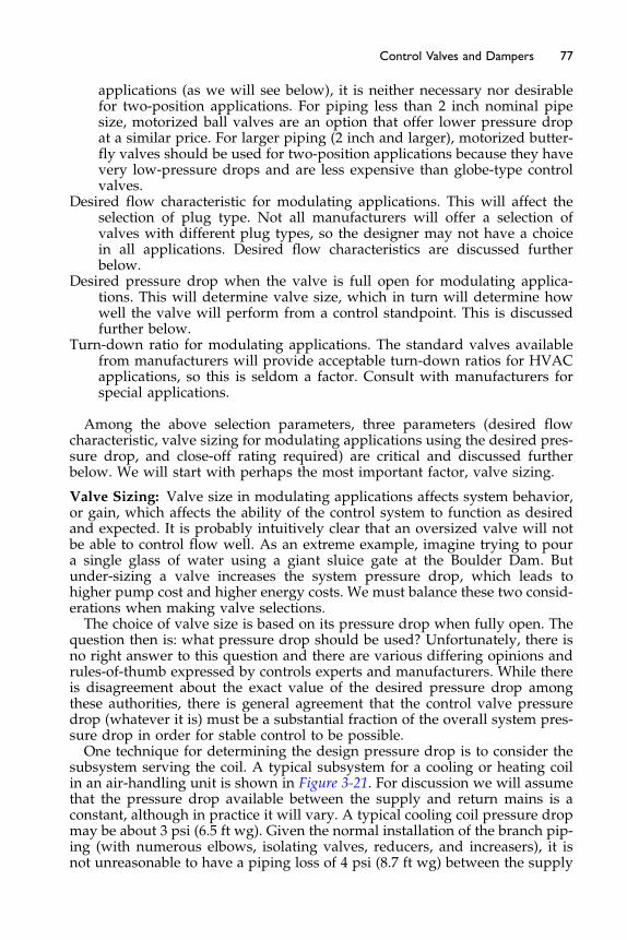
77Control Valves and Dampers
applications (as we will see below), it is neither necessary nor desirablefor two-position applications. For piping less than 2 inch nominal pipesize, motorized ball valves are an option that offer lower pressure dropat a similar price. For larger piping (2 inch and larger), motorized butter-fly valves should be used for two-position applications because they havevery low-pressure drops and are less expensive than globe-type controlvalves.
Desired flow characteristic for modulating applications. This will affect theselection of plug type. Not all manufacturers will offer a selection ofvalves with different plug types, so the designer may not have a choicein all applications. Desired flow characteristics are discussed furtherbelow.
Desired pressure drop when the valve is full open for modulating applica-tions. This will determine valve size, which in turn will determine howwell the valve will perform from a control standpoint. This is discussedfurther below.
Turn-down ratio for modulating applications. The standard valves availablefrom manufacturers will provide acceptable turn-down ratios for HVACapplications, so this is seldom a factor. Consult with manufacturers forspecial applications.
Among the above selection parameters, three parameters (desired flowcharacteristic, valve sizing for modulating applications using the desired pres-sure drop, and close-off rating required) are critical and discussed furtherbelow. We will start with perhaps the most important factor, valve sizing.
Valve Sizing: Valve size in modulating applications affects system behavior,or gain, which affects the ability of the control system to function as desiredand expected. It is probably intuitively clear that an oversized valve will notbe able to control flow well. As an extreme example, imagine trying to poura single glass of water using a giant sluice gate at the Boulder Dam. Butunder-sizing a valve increases the system pressure drop, which leads tohigher pump cost and higher energy costs. We must balance these two consid-erations when making valve selections.The choice of valve size is based on its pressure drop when fully open. The
question then is: what pressure drop should be used? Unfortunately, there isno right answer to this question and there are various differing opinions andrules-of-thumb expressed by controls experts and manufacturers. While thereis disagreement about the exact value of the desired pressure drop amongthese authorities, there is general agreement that the control valve pressuredrop (whatever it is) must be a substantial fraction of the overall system pres-sure drop in order for stable control to be possible.One technique for determining the design pressure drop is to consider the
subsystem serving the coil. A typical subsystem for a cooling or heating coilin an air-handling unit is shown in Figure 3-21. For discussion we will assumethat the pressure drop available between the supply and return mains is aconstant, although in practice it will vary. A typical cooling coil pressure dropmay be about 3 psi (6.5 ft wg). Given the normal installation of the branch pip-ing (with numerous elbows, isolating valves, reducers, and increasers), it isnot unreasonable to have a piping loss of 4 psi (8.7 ft wg) between the supply
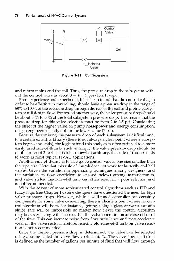
S
Main
ControlValve
IsolatingValve
R
Coil
Figure 3-21 Coil Subsystem
78 Fundamentals of HVAC Control Systems
and return mains and the coil. Thus, the pressure drop in the subsystem with-out the control valve is about 3 þ 4 ¼ 7 psi (15.2 ft wg).
From experience and experiment, it has been found that the control valve, inorder to be effective in controlling, should have a pressure drop in the range of50% to 100% of the pressure drop through the rest of the coil and piping subsys-tem at full design flow. Expressed another way, the valve pressure drop shouldbe about 30% to 50% of the total subsystem pressure drop. This means that thepressure drop for this valve selection must be from 2 to 3.5 psi. Consideringthe effect of the higher value on pump horsepower and energy consumption,design engineers usually opt for the lower value (2 psi).
Because determining the pressure drop of each subsystem is difficult and,to a certain extent, arbitrary (there is not always a clear point where a subsys-tem begins and ends), the logic behind this analysis is often reduced to a moreeasily used rule-of-thumb, such as simply: the valve pressure drop should beon the order of 2 to 4 psi. While somewhat arbitrary, this rule-of-thumb tendsto work in most typical HVAC applications.
Another rule-of-thumb is to size globe control valves one size smaller thanthe pipe size. Note that this rule-of-thumb does not work for butterfly and ballvalves. Given the variation in pipe sizing techniques among designers, andthe variation in flow coefficient (discussed below) among manufacturers,and valve styles, this rule-of-thumb can often result in a poor selection andis not recommended.
With the advent of more sophisticated control algorithms such as PID andfuzzy logic (see Chapter 1), some designers have questioned the need for highvalve pressure drops. However, while a well-tuned controller can certainlycompensate for some valve over-sizing, there is clearly a point where no con-trol algorithm will help. For instance, getting a single glass of water out of asluice gate will be impossible no matter how clever the control algorithmmay be. Over-sizing will also result in the valve operating near close-off mostof the time. This can increase noise from flow turbulence and may acceleratewear on the valve seats. Therefore, relaxing old rules-of-thumb on valve selec-tion is not recommended.
Once the desired pressure drop is determined, the valve can be selectedusing a rating called the valve flow coefficient, Cv. The valve flow coefficientis defined as the number of gallons per minute of fluid that will flow through
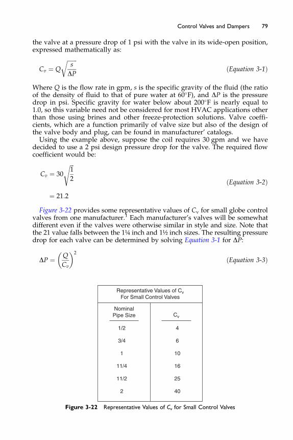
79Control Valves and Dampers
the valve at a pressure drop of 1 psi with the valve in its wide-open position,expressed mathematically as:
Cv ¼ Q
ffiffiffiffiffiffiffis
DP
r
ðEquation 3-1Þ
Where Q is the flow rate in gpm, s is the specific gravity of the fluid (the ratioof the density of fluid to that of pure water at 60�F), and DP is the pressuredrop in psi. Specific gravity for water below about 200�F is nearly equal to1.0, so this variable need not be considered for most HVAC applications otherthan those using brines and other freeze-protection solutions. Valve coeffi-cients, which are a function primarily of valve size but also of the design ofthe valve body and plug, can be found in manufacturer’ catalogs.Using the example above, suppose the coil requires 30 gpm and we have
decided to use a 2 psi design pressure drop for the valve. The required flowcoefficient would be:
Cv ¼ 30
ffiffiffi1
2
s
¼ 21:2
ðEquation 3-2Þ
Figure 3-22 provides some representative values of Cv for small globe controlvalves from one manufacturer.1 Each manufacturer’s valves will be somewhatdifferent even if the valves were otherwise similar in style and size. Note thatthe 21 value falls between the 1¼ inch and 1½ inch sizes. The resulting pressuredrop for each valve can be determined by solving Equation 3-1 for DP:
DP ¼ Q
Cv
� �2
ðEquation 3-3Þ
Representative Values of CvFor Small Control Valves
NominalPipe Size
1/2
1
2
3/4
11/4
11/2
Cv
4
6
10
16
25
40
Figure 3-22 Representative Values of Cv for Small Control Valves

80 Fundamentals of HVAC Control Systems
For the 1¼ inch valve, the pressure drop would be 3.5 psi (7.6 ft) while forthe 1½ in. valve, the pressure drop would be 1.5 psi (3.3 ft). The latter is mar-ginal (it amounts to less than 30% of the branch pressure drop, excluding thevalve itself), so the 1½ inch valve may not provide good control. On the otherhand, if the pump capacity was based on the assumption of a 2 psi designpressure drop across the valve, using the smaller valve, while providing bettercontrol, could make the pump inadequate. Unfortunately, there are onlyincremental values of Cv available, so the designer often must make a difficultdecision. In general, it is recommended that the selection lean toward thesmaller valve rather than the larger because:
Only control valves in the circuit with the highest pressure drop will affect thepump head requirement. All other valves, particularly those closest tothe pump where the available pressure differential is usually highest,can be undersized without impacting pump selection or pump energyusage.
Because design loads are seldom encountered, most control valves will oper-ate most of the time over a range from 10% to 50% open. It follows thatusing a higher design pressure drop through the valve will allow bettercontrol most of the time.
In variable flow, two-way valve systems, the differential pressure across thevalve can increase, depending on how the pump is controlled. This is par-ticularly true at low flow rates that, as noted above, are the predominantoperating condition. Therefore, the valve will appear to be even moreoversized as it has to absorb the higher pressure. A smaller valve willimprove control under these conditions.
Good control will also affect energy efficiency of the system. For instance, if anoversized valve results in overcooled supply air on a VAV system, thereheat coils at the zone level may have to compensate, increasing heatingenergy. This may offset any savings gained in pump energy from thereduced valve pressure drop.
An oversized valve on a cooling coil may result in a higher flow and the waterleaving the coil at a lower temperature than designed. Returning cold,chilled water (low delta T) can severely reduce chiller plant efficiency.
About the only time where it may be practical to lean toward over-sizingcontrol valves is when supply water temperature is aggressively reset basedon system load or load indicators such as outdoor air temperature. This tendsto keep flow rates high and minimizes the need for valve throttling. But resetmay not be possible under all operating conditions. For instance, on chilledwater systems, reset may be limited by the need to maintain dehumidificationcapability at coils.
For butterfly valves, available flow coefficients are usually very large (pres-sure drops are very low) and a satisfactory pressure drop may not be possibleunless the valve is very small relative to the flow rate. However, for valves thissmall, the velocity through the valve will usually be above the manufacturer’srecommended maximum allowable velocity, above which impingement ero-sion can negatively affect valve service life. It is for this reason that butterflyvalves are not usually the best choice for modulating control duty, wherewidely varying flow rates are expected and when precise control is required.
81Control Valves and Dampers
When accurate control at low flows is not critical, butterfly valves one ortwo pipe sizes smaller than the pipe size may be perfectly satisfactory. Twoslightly different procedures are adopted in this situation. The first is thatvalve is sized based on the Cv for the valve when 60% open is commonly usedinstead of the Cv when fully open as for other valves. The second issue is thatwhen the valve size is smaller than the pipe size the flow is not as smooth.This effectively reduces the Cv of the valve (increases the apparent resistance),and is called the piping geometry factor. For example, a 1½ inch valve mighthave a Cv of 150 in a run of 2½ inch pipe, 123 in a run of 3 inch pipe, and 80 ina run of 4 inch pipe.Ball valves also used to have low flow coefficients. This disadvantage has
been largely overcome by the use of specially shaped inserts. These insertsrestrict the flow through the adjustable ball to give specific characteristics.This use of inserts enables manufacturers to provide, in smaller sizes, a rangeoff flow coefficients for each valve size.Note that the discussion above did not distinguish between two-way and
three-way valves. From the point of view of the coil, the two are the same;they both result in the same modulation of flow through the coil. Therefore,the same design considerations, and thus the same sizing techniques, applyto both styles. However, pressure differential across the valve and coil inthree-way valve, constant flow systems tends to stay fairly constant, whilethat in two-way valve systems can increase depending on pump controls used(this is discussed in more detail below). Therefore, oversized three-way valvesmay be slightly more forgiving than oversized two-way valves.
Flow Characteristic Selection
Plug selection depends on the desired flow characteristic, which is a function of:
The heat transfer device being controlled (for example, chilled water coil, hotwater coil) and its flow versus capacity characteristic.
The control of fluid supply temperature, which has an impact on the flow ver-sus capacity characteristic of the heat transfer device.
The control of the differential pressure across the valve, which affects theamount of pressure that must be absorbed by the valve.
Figure 3-23 shows typical flow versus capacity curves for heating and coolingcoils. For heating coils, the curves can be very nonlinear due to the high tempera-ture of thewater compared to the air it is heating. Flowmust fall below about 50%before heating capacity falls below 80%. This characteristic becomes even morepronounced when coils are designed for high flow (low temperature drop).This non-linear performance can be corrected by resetting the hot water sup-
ply temperature, which causes the hot water temperature to draw nearer to thetemperature of the air it is heating, thereby effectively reducing the heatingcapacity of the coil. As can be seen in Figure 3-23, the result of hot water temper-ature set point reset is to linearize the coil’s response to flow variation.Sensible capacity characteristics of chilled water coils tend to be fairly linear
inherently due to the closeness of the chilled water and air temperatures.At low flow rates, the flow in coil tubes becomes low enough that turbu-
lence drops and the flow smoothes out into a flow regime called laminar flow.
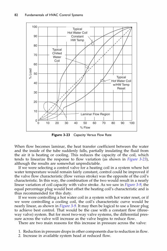
100
90
80
70
60
50
40
30
20
10
00 10 20 30 40 50 60
% Flow
70 80 90 100
Laminar Flow Region
% L
oad
TypicalHot Water Coilw/HW Temp
Reset
TypicalHot Water Coil
ConstantHW Temp
TypicalChilledWaterCoil
Figure 3-23 Capacity Versus Flow Rate
82 Fundamentals of HVAC Control Systems
When flow becomes laminar, the heat transfer coefficient between the waterand the inside of the tube suddenly falls, partially insulating the fluid fromthe air it is heating or cooling. This reduces the capacity of the coil, whichtends to linearize the response to flow variation (as shown in Figure 3-23),although the results are somewhat unpredictable.
If we were selecting a control valve for a heating coil in a system where hotwater temperature would remain fairly constant, control could be improved ifthe valve flow characteristic (flow versus stroke) was the opposite of the coil’scharacteristic. In this way, the combination of the two would result in a nearlylinear variation of coil capacity with valve stroke. As we saw in Figure 3-9, theequal percentage plug would best offset the heating coil’s characteristic and isthus recommended for this duty.
If we were controlling a hot water coil in a system with hot water reset, or ifwe were controlling a cooling coil, the coil’s characteristic curve would benearly linear, as shown in Figure 3-9. It may then be logical to use a linear plugto achieve best control. That would be the case with a constant flow (three-way valve) system. But for most two-way valve systems, the differential pres-sure across the valve will increase as the valve begins to reduce flow.
There are two main reasons for this increase in pressure across the valve:
1. Reduction in pressure drops in other components due to reduction in flow.2. Increase in available system head at reduced flow.

83Control Valves and Dampers
Let us consider the reduction in pressure drops in other components due toreduction in flow. In an earlier example the pressure drops were given as coil3 psi, pipework with fittings 4 psi, and control valve 3.5 psi, all at full flow.The flow for this example is 30 gpm and our system provides an almost con-stant head of 10.5 psi.The pressure drop across a fixed component is typically, proportional to the
square of the flow. Pressure drop P ¼ K gpm2
For our coil, P ¼ 3 psi at 100 gpm. 3 ¼ K�1002, so K ¼ 0.0003At 50% flow P ¼ 0.0003�502 ¼ 0.75 psi, one-quarter the pressure drop.In general, if the flow is reduced to 50% the pressure drop will drop to 25%Now our circuit has a constant head, so as the flow reduces and the pres-
sure drop across the coil and pipework reduces the head across the valveincreases. This is shown in Table 3-1 where the valve pressure drop increasesfrom 8 psi to 16 psi as the valve moves to 50% flow in each branch. You mayhave noticed that the flow at 50% and 50% is given as 132 gpm, not 50 þ 50¼100 gpm. The reason for this is that the linear characteristic of the valveoccurs with constant head across the valve. Since the head across the valvehas increased the characteristic is distorted to let more water through.The second issue was the increase in available system head at reduced flow.
Consider a very simple circuit including piped coil, two-way control valve,and a pump. The pump will have a flow performance curve with maximumpressure at no flow and the pressure gradually dropping as the flowincreases. Our piped coil has a characteristic flow/head curve which obeysthe relationship P ¼ K gpm2. Initially, at design flow, the valve has a head lossequal to the piped coil. The situation is as shown in Figure 3-24.With the valve fully open the flow will be at point A. The pump head
matches the head across the valve plus the head across the piped coil. Now,as the valve closes, the flow reduces and the pressure drop through the pipedcoil reduces. At the same time the pump flow is reduced, and its headincreases. The result is flow at point B and the pressure drop across the valvehas approximately doubled.One way of reducing this effect is to maintain a constant head from the
pump by reducing the pump speed. Suppose this did, in fact, maintain thehead at the original full at point A flow head, as shown by the broken line.The valve head, pressure differential, is still increased as the flow in the pipedcoil reduces with reducing flow.The increase in pressure differential tends to distort the plug characteristic
curve because more flow will go through the valve at the same valve positioncompared to the flow at a fixed differential. This is called authority distortion.
Table 3-1 Pressure/Flow Variations in Control Circuit
Pressure Drops in Coil Circuit in psi
Item 100% Through Coil 50% Through Coil 0% Through Coil
Pipe and fittings 4 1.0 0Coil 3 0.75 0Linear control valve 3.5 8.75 10.5System head (constant) 10.5 10.5 10.5Total flow coil and bypass gpm 30 �40 30
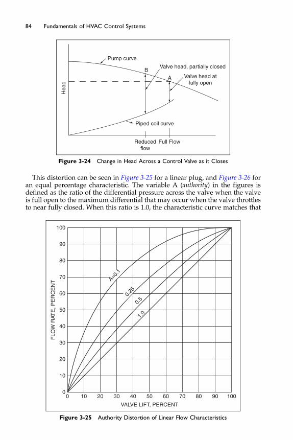
Hea
dPump curve
BValve head, partially closed
Valve head atfully open
Piped coil curve
Reducedflow
Full Flow
A
Figure 3-24 Change in Head Across a Control Valve as it Closes
84 Fundamentals of HVAC Control Systems
This distortion can be seen in Figure 3-25 for a linear plug, and Figure 3-26 foran equal percentage characteristic. The variable A (authority) in the figures isdefined as the ratio of the differential pressure across the valve when the valveis full open to the maximum differential that may occur when the valve throttlesto near fully closed. When this ratio is 1.0, the characteristic curve matches that
100
90
80
70
60
50
40
30
20
10
00 10 20 30 40 50 60
VALVE LIFT, PERCENT
70 80 90 100
FLO
W R
ATE
, PE
RC
EN
T A=0.1
0.25
0.5
1.0
Figure 3-25 Authority Distortion of Linear Flow Characteristics
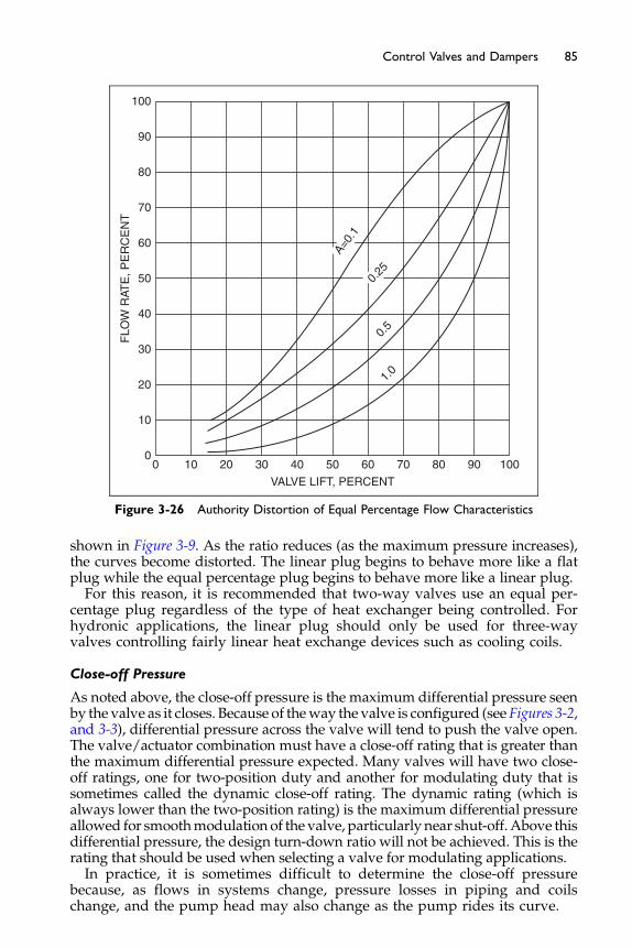
100
90
80
70
60
50
40
30
20
10
00 10 20 30 40 50 60
VALVE LIFT, PERCENT
70 80 90 100
FLO
W R
ATE
, PE
RC
EN
T
A=0.1
0.5
1.0
0.25
Figure 3-26 Authority Distortion of Equal Percentage Flow Characteristics
85Control Valves and Dampers
shown in Figure 3-9. As the ratio reduces (as the maximum pressure increases),the curves become distorted. The linear plug begins to behave more like a flatplug while the equal percentage plug begins to behave more like a linear plug.For this reason, it is recommended that two-way valves use an equal per-
centage plug regardless of the type of heat exchanger being controlled. Forhydronic applications, the linear plug should only be used for three-wayvalves controlling fairly linear heat exchange devices such as cooling coils.
Close-off Pressure
As noted above, the close-off pressure is the maximum differential pressure seenby the valve as it closes. Because of theway the valve is configured (see Figures 3-2,and 3-3), differential pressure across the valve will tend to push the valve open.The valve/actuator combination must have a close-off rating that is greater thanthe maximum differential pressure expected. Many valves will have two close-off ratings, one for two-position duty and another for modulating duty that issometimes called the dynamic close-off rating. The dynamic rating (which isalways lower than the two-position rating) is the maximum differential pressureallowed for smoothmodulation of the valve, particularly near shut-off.Above thisdifferential pressure, the design turn-down ratio will not be achieved. This is therating that should be used when selecting a valve for modulating applications.In practice, it is sometimes difficult to determine the close-off pressure
because, as flows in systems change, pressure losses in piping and coilschange, and the pump head may also change as the pump rides its curve.
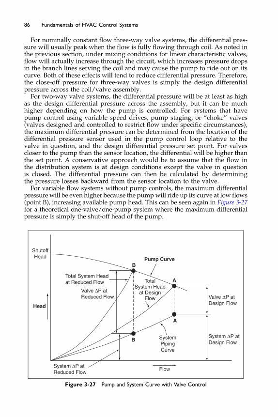
86 Fundamentals of HVAC Control Systems
For nominally constant flow three-way valve systems, the differential pres-sure will usually peak when the flow is fully flowing through coil. As noted inthe previous section, under mixing conditions for linear characteristic valves,flow will actually increase through the circuit, which increases pressure dropsin the branch lines serving the coil and may cause the pump to ride out on itscurve. Both of these effects will tend to reduce differential pressure. Therefore,the close-off pressure for three-way valves is simply the design differentialpressure across the coil/valve assembly.
For two-way valve systems, the differential pressure will be at least as highas the design differential pressure across the assembly, but it can be muchhigher depending on how the pump is controlled. For systems that havepump control using variable speed drives, pump staging, or “choke” valves(valves designed and controlled to restrict flow under specific circumstances),the maximum differential pressure can be determined from the location of thedifferential pressure sensor used in the pump control loop relative to thevalve in question, and the design differential pressure set point. For valvescloser to the pump than the sensor location, the differential will be higher thanthe set point. A conservative approach would be to assume that the flow inthe distribution system is at design conditions except the valve in questionis closed. The differential pressure can then be calculated by determiningthe pressure losses backward from the sensor location to the valve.
For variable flow systems without pump controls, the maximum differentialpressure will be even higher because the pumpwill ride up its curve at low flows(point B), increasing available pump head. This can be seen again in Figure 3-27for a theoretical one-valve/one-pump system where the maximum differentialpressure is simply the shut-off head of the pump.
Total System Headat Reduced Flow
Valve ΔP atReduced Flow
System ΔP atReduced Flow
Valve ΔP atDesign Flow
Pump Curve
A
B
A
BSystem ΔP atDesign Flow
ShutoffHead
Head
TotalSystem Head
at DesignFlow
SystemPipingCurve
Flow
Figure 3-27 Pump and System Curve with Valve Control
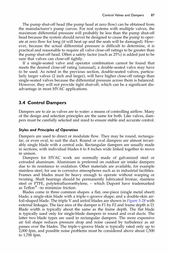
87Control Valves and Dampers
The pump shut-off head (the pump head at zero flow) can be obtained fromthe manufacturer’s pump curves. For real systems with multiple valves, themaximum differential pressure will probably be less than the pump shut-offhead because the system should never be designed to cause the pump to oper-ate at zero flow for long (it will heat up and the seals will be damaged). How-ever, because the actual differential pressure is difficult to determine, it ispractical and reasonable to require all valve close-off ratings to be greater thanthe pump shut-off head. Often a safety factor (such as 25%) is added just to besure that valves can close-off tightly.If a single-seated valve and operator combination cannot be found that
meets the desired close-off rating (unusual), a double-seated valve may haveto be used. As noted in the previous section, double-seated valves, particu-larly larger valves (2 inch and larger), will have higher close-off ratings thansingle-seated valves because the differential pressure across them is balanced.However, they will not provide tight shut-off, which can be a significant dis-advantage in most HVAC applications.
3.4 Control Dampers
Dampers are to air as valves are to water: a means of controlling airflow. Manyof the design and selection principles are the same for both. Like valves, dam-pers must be carefully selected and sized to ensure stable and accurate control.
Styles and Principles of Operation
Dampers are used to direct or modulate flow. They may be round, rectangu-lar, or even oval, to suit the duct. Round or oval dampers are almost invari-ably single blade with a central axle. Rectangular dampers are usually madein sections, with individual blades 6 to 8 inches wide linked together to movein unison.Dampers for HVAC work are normally made of galvanized steel or
extruded aluminum. Aluminum is preferred on outdoor air intake dampersdue to its resistance to oxidation. Other materials are available, for examplestainless steel, for use in corrosive atmospheres such as in industrial facilities.Frames and blades must be heavy enough to operate without warping ortwisting. Shaft bearings should be permanently lubricated bronze, stainlesssteel or PTFE, polytetrafluoroethylene, – which Dupont have trademarkedas TeflonW –to minimize friction.Blades come in three common shapes: a flat, one-piece (single metal sheet)
blade; a single-skin blade with a triple-v-groove shape; and a double-skin air-foil-shaped blade. The triple V and airfoil blades are shown in Figure 3-28 withexternal linkages. The face area of the damper is F1 by F2 and frame depth is D.Blade width is typically about the same as the frame depth. The flat bladeis typically used only for single-blade dampers in round and oval ducts. Thelatter two blade types are used in rectangular dampers. The more expensiveair foil shape reduces pressure drop and noise caused by turbulence as airpasses over the blades. The triple-v-groove blade is typically rated only up to2,000 fpm, and possible noise problems must be considered above about 1,500to 1,700 fpm.
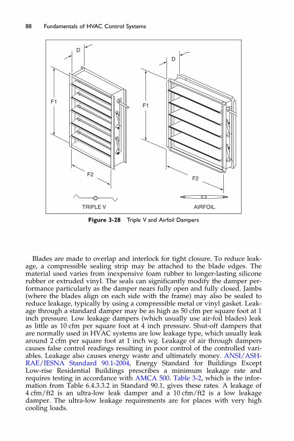
D
D
F1F1
F2F2
TRIPLE V AIRFOIL
Figure 3-28 Triple V and Airfoil Dampers
88 Fundamentals of HVAC Control Systems
Blades are made to overlap and interlock for tight closure. To reduce leak-age, a compressible sealing strip may be attached to the blade edges. Thematerial used varies from inexpensive foam rubber to longer-lasting siliconerubber or extruded vinyl. The seals can significantly modify the damper per-formance particularly as the damper nears fully open and fully closed. Jambs(where the blades align on each side with the frame) may also be sealed toreduce leakage, typically by using a compressible metal or vinyl gasket. Leak-age through a standard damper may be as high as 50 cfm per square foot at 1inch pressure. Low leakage dampers (which usually use air-foil blades) leakas little as 10 cfm per square foot at 4 inch pressure. Shut-off dampers thatare normally used in HVAC systems are low leakage type, which usually leakaround 2 cfm per square foot at 1 inch wg. Leakage of air through damperscauses false control readings resulting in poor control of the controlled vari-ables. Leakage also causes energy waste and ultimately money. ANSI/ASH-RAE/IESNA Standard 90.1-2004, Energy Standard for Buildings ExceptLow-rise Residential Buildings prescribes a minimum leakage rate andrequires testing in accordance with AMCA 500. Table 3-2, which is the infor-mation from Table 6.4.3.3.2 in Standard 90.1, gives these rates. A leakage of4 cfm/ft2 is an ultra-low leak damper and a 10 cfm/ft2 is a low leakagedamper. The ultra-low leakage requirements are for places with very highcooling loads.
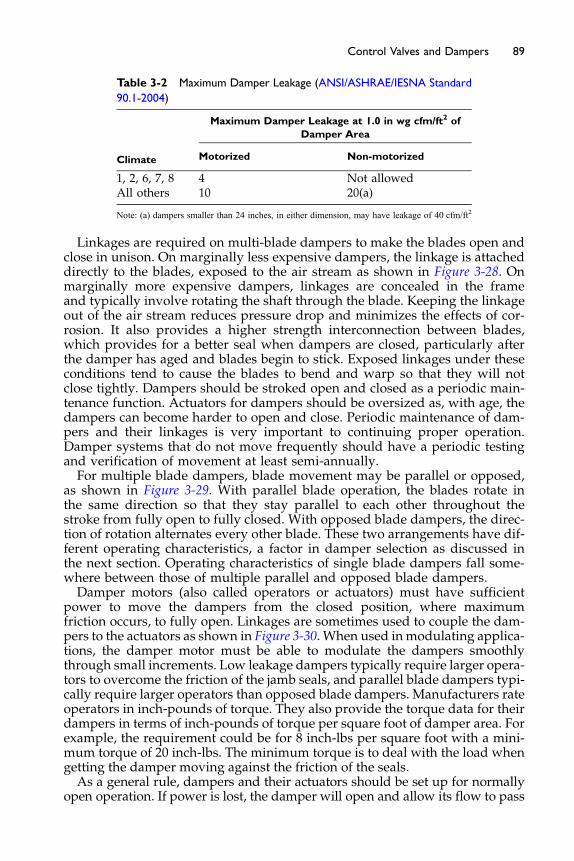
Table 3-2 Maximum Damper Leakage (ANSI/ASHRAE/IESNA Standard
90.1-2004)
Maximum Damper Leakage at 1.0 in wg cfm/ft2 of
Damper Area
Climate Motorized Non-motorized
1, 2, 6, 7, 8 4 Not allowedAll others 10 20(a)
Note: (a) dampers smaller than 24 inches, in either dimension, may have leakage of 40 cfm/ft2
89Control Valves and Dampers
Linkages are required on multi-blade dampers to make the blades open andclose in unison. On marginally less expensive dampers, the linkage is attacheddirectly to the blades, exposed to the air stream as shown in Figure 3-28. Onmarginally more expensive dampers, linkages are concealed in the frameand typically involve rotating the shaft through the blade. Keeping the linkageout of the air stream reduces pressure drop and minimizes the effects of cor-rosion. It also provides a higher strength interconnection between blades,which provides for a better seal when dampers are closed, particularly afterthe damper has aged and blades begin to stick. Exposed linkages under theseconditions tend to cause the blades to bend and warp so that they will notclose tightly. Dampers should be stroked open and closed as a periodic main-tenance function. Actuators for dampers should be oversized as, with age, thedampers can become harder to open and close. Periodic maintenance of dam-pers and their linkages is very important to continuing proper operation.Damper systems that do not move frequently should have a periodic testingand verification of movement at least semi-annually.For multiple blade dampers, blade movement may be parallel or opposed,
as shown in Figure 3-29. With parallel blade operation, the blades rotate inthe same direction so that they stay parallel to each other throughout thestroke from fully open to fully closed. With opposed blade dampers, the direc-tion of rotation alternates every other blade. These two arrangements have dif-ferent operating characteristics, a factor in damper selection as discussed inthe next section. Operating characteristics of single blade dampers fall some-where between those of multiple parallel and opposed blade dampers.Damper motors (also called operators or actuators) must have sufficient
power to move the dampers from the closed position, where maximumfriction occurs, to fully open. Linkages are sometimes used to couple the dam-pers to the actuators as shown in Figure 3-30. When used inmodulating applica-tions, the damper motor must be able to modulate the dampers smoothlythrough small increments. Low leakage dampers typically require larger opera-tors to overcome the friction of the jamb seals, and parallel blade dampers typi-cally require larger operators than opposed blade dampers. Manufacturers rateoperators in inch-pounds of torque. They also provide the torque data for theirdampers in terms of inch-pounds of torque per square foot of damper area. Forexample, the requirement could be for 8 inch-lbs per square foot with a mini-mum torque of 20 inch-lbs. The minimum torque is to deal with the load whengetting the damper moving against the friction of the seals.As a general rule, dampers and their actuators should be set up for normally
open operation. If power is lost, the damper will open and allow its flow to pass
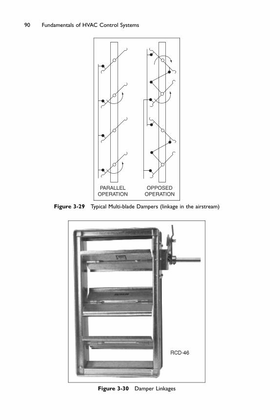
PARALLELOPERATION
OPPOSEDOPERATION
Figure 3-29 Typical Multi-blade Dampers (linkage in the airstream)
Figure 3-30 Damper Linkages
90 Fundamentals of HVAC Control Systems

91Control Valves and Dampers
until repairs can be made to its automatic operation. The exception to thiswould be dampers protecting coils from freezing, and dampers guarding dan-gerous, hazardous waste, or isolation systems.
3.5 Selecting and Sizing Dampers
There are three basic damper applications:
� Two-position duty, such as shut-off of outdoor air intakes, fan isolation, etc.� Capacity control duty, such as air balancing and VAV discharge dampers.� Mixing duty, such as economizer dampers.
Two-position Duty
Dampers are commonly placed in outdoor air intakes, fan intakes and dis-charges, and other positions where they are used to prevent air flow fromoccurring when the fan system is shut off. These dampers have two-positions:they are open when the system is on and closed when the system is off. Forinstance, a damper placed in an outdoor air intake might be interlocked tothe supply fan to close when the fan is off to minimize air infiltration causedby wind or stack effect, thereby protecting coils from freezing in cold weatherand reducing energy costs.Dampers in exhaust fan inlets or discharges are another common shut-off
application. These dampers may be motorized or they may be gravity dam-pers (also called backdraft or barometric dampers), meaning they work with-out actuators. Gravity dampers seldom offer as tight a seal as motorizeddampers. They also only work to prevent air flow in one direction but notthe other, and thus may not always achieve the desired result. For instance,on an exhaust fan, a backdraft damper may prevent outdoor air from cominginto the building backward through the exhaust air discharge point when thefan is off, but it will not prevent air from going out that discharge point in thenormal direction of flow. In a tall building, during cold weather, stack effectcan cause enough air pressure to push the gravity damper open, allowingbuilding air to flow out the exhaust system, with corresponding makeup airdrawn into the building at lower floors. In these applications, a motorizeddamper is therefore recommended.In specific situations, gravity dampers are preferred to motorized dampers.
For instance, two fans operating in parallel (see Figure 3-31) generally are fittedwith dampers to isolate the fans so that one may operate without the other.This will allow lead/lag operation in variable air volume (VAV) applica-
tions (staging of fans so that only one operates at low loads), and provideredundancy by allowing one fan to operate in case the other fails. Withoutsome type of shut-off damper, the operating fan would cause air to flow back-ward through the inoperative fan (analogous to the need for check valves inparallel pumping systems).In this application, if a motorized damper is used, there is a question as to
when the damper should open. If the damper is opened before the fan is turnedon, then while the damper is opening, air will backflow from the other fan,which may already be operating. This will cause the fan wheel to spin
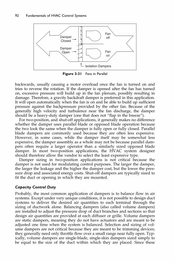
DamperClosed
Fanoff
Fanon
Isolation Dampers
DamperOpen
Figure 3-31 Fans in Parallel
92 Fundamentals of HVAC Control Systems
backwards, usually causing a motor overload once the fan is turned on andtries to reverse the rotation. If the damper is opened after the fan has turnedon, excessive pressure will build up in the fan plenum, possibly resulting indamage. Therefore, a gravity backdraft damper is preferred in this application.It will open automatically when the fan is on and be able to build up sufficientpressure against the backpressure provided by the other fan. Because of thegenerally high velocity and turbulence near the fan discharge, the dampershould be a heavy-duty damper (one that does not “flap in the breeze”).
For two-position, and shut-off applications, it generally makes no differencewhether the damper uses parallel blade or opposed blade operation becausethe two look the same when the damper is fully open or fully closed. Parallelblade dampers are commonly used because they are often less expensive.However, in some cases, while the damper itself may be somewhat lessexpensive, the damper assembly as a whole may not be because parallel dam-pers often require a larger operator than a similarly sized opposed bladedamper. In most two-position applications, the HVAC system designershould therefore allow the vendor to select the least expensive type.
Damper sizing in two-position applications is not critical because thedamper is not used for modulating control purposes. The larger the damper,the larger the leakage and the higher the damper cost, but the lower the pres-sure drop and associated energy costs. Shut-off dampers are typically sized tofit the duct or opening in which they are mounted.
Capacity Control Duty
Probably, the most common application of dampers is to balance flow in airsystems. Except under very unique conditions, it is not possible to design ductsystems to deliver the desired air quantities to each terminal through thesizing of ductwork alone. Balancing dampers (also called volume dampers)are installed to adjust the pressure drop of duct branches and sections so thatdesign air quantities are provided at each diffuser or grille. Volume dampersare static dampers, meaning they do not have actuators and are meant to beadjusted one time when the system is balanced. Selection and sizing of vol-ume dampers are not critical because they are meant to be trimming devices;they generally need only throttle flow over a small range near fully open. Typ-ically, volume dampers are single-blade, single-skin dampers sized simply tobe equal to the size of the duct within which they are placed. Since these
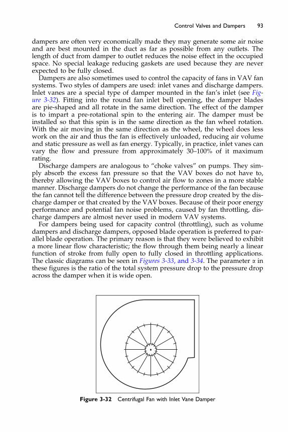
93Control Valves and Dampers
dampers are often very economically made they may generate some air noiseand are best mounted in the duct as far as possible from any outlets. Thelength of duct from damper to outlet reduces the noise effect in the occupiedspace. No special leakage reducing gaskets are used because they are neverexpected to be fully closed.Dampers are also sometimes used to control the capacity of fans in VAV fan
systems. Two styles of dampers are used: inlet vanes and discharge dampers.Inlet vanes are a special type of damper mounted in the fan’s inlet (see Fig-ure 3-32). Fitting into the round fan inlet bell opening, the damper bladesare pie-shaped and all rotate in the same direction. The effect of the damperis to impart a pre-rotational spin to the entering air. The damper must beinstalled so that this spin is in the same direction as the fan wheel rotation.With the air moving in the same direction as the wheel, the wheel does lesswork on the air and thus the fan is effectively unloaded, reducing air volumeand static pressure as well as fan energy. Typically, in practice, inlet vanes canvary the flow and pressure from approximately 30–100% of it maximumrating.Discharge dampers are analogous to “choke valves” on pumps. They sim-
ply absorb the excess fan pressure so that the VAV boxes do not have to,thereby allowing the VAV boxes to control air flow to zones in a more stablemanner. Discharge dampers do not change the performance of the fan becausethe fan cannot tell the difference between the pressure drop created by the dis-charge damper or that created by the VAV boxes. Because of their poor energyperformance and potential fan noise problems, caused by fan throttling, dis-charge dampers are almost never used in modern VAV systems.For dampers being used for capacity control (throttling), such as volume
dampers and discharge dampers, opposed blade operation is preferred to par-allel blade operation. The primary reason is that they were believed to exhibita more linear flow characteristic; the flow through them being nearly a linearfunction of stroke from fully open to fully closed in throttling applications.The classic diagrams can be seen in Figures 3-33, and 3-34. The parameter a inthese figures is the ratio of the total system pressure drop to the pressure dropacross the damper when it is wide open.
Figure 3-32 Centrifugal Fan with Inlet Vane Damper
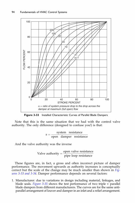
00
20
40FLO
W P
ER
CE
NT
60
80
100
20 40STROKE PERCENT
α = ratio of system pressure drop to the drop across thedamper at maximum (full open) flow
60
200
10050
20
105
32α=1
80 100
Figure 3-33 Installed Characteristic Curves of Parallel Blade Dampers
94 Fundamentals of HVAC Control Systems
Note that this is the same situation that we had with the control valveauthority. The only difference (designed to confuse you!) is that:
a ¼ system resistance
open damper resistance
And the valve authority was the inverse
Valve authority ¼ open valve resistance
pipe loop resistance
These figures are, in fact, a gross and often incorrect picture of damperperformance. The movement upwards as authority increases is conceptuallycorrect but the scale of the change may be much smaller than shown in Fig-ures 3-33 and 3-34. Damper performance depends on several factors:
1. Manufacturer: due to variations in design including material, linkages, andblade seals. Figure 3-35 shows the test performance of two triple v parallelblade dampers from different manufacturers. The curves are for the same anti-parallel arrangement of louver and damper in an inlet and a relief arrangement.
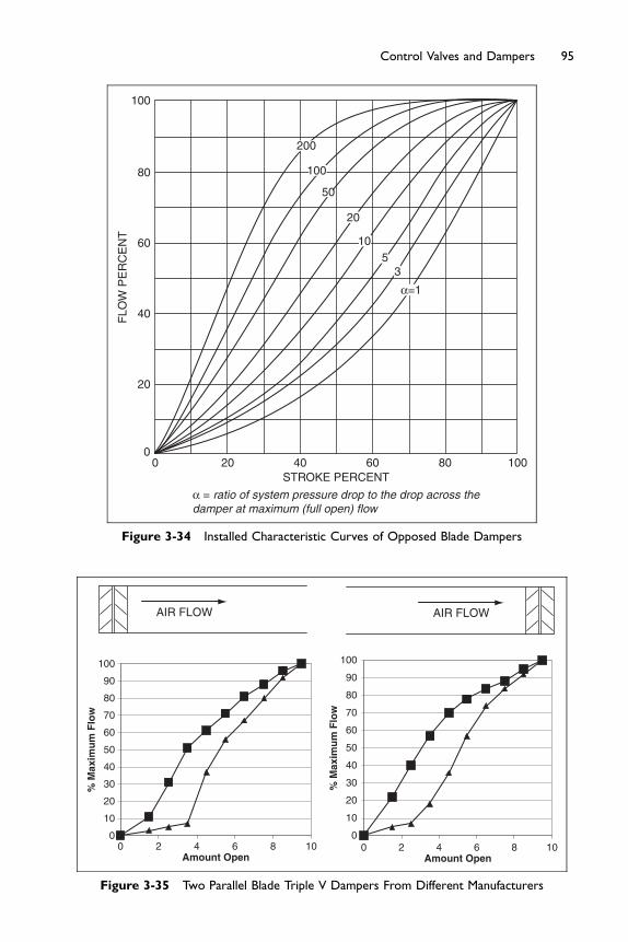
0
10
20
30
40
50
60
70
80
90
100
0 2 4 6 8 10Amount Open
% M
axim
um
Flo
w
0
10
20
30
40
50
60
70
80
90
100
0 2 4 6 8 10Amount Open
% M
axim
um
Flo
w
AIR FLOW AIR FLOW
Figure 3-35 Two Parallel Blade Triple V Dampers From Different Manufacturers
00
20
40FLO
W P
ER
CE
NT
60
80
100
20 40STROKE PERCENT
60
α = ratio of system pressure drop to the drop across thedamper at maximum (full open) flow
200
100
50
20
105
3
α=1
80 100
Figure 3-34 Installed Characteristic Curves of Opposed Blade Dampers
95Control Valves and Dampers

0
10
20
30
40
50
60
70
80
90
100
0 2 4 6 8 10Amount Open
% M
axim
um
Flo
w
0
10
20
30
40
50
60
70
80
90
100
0 2 4 6 8 10Amount Open
% M
axim
um
Flo
w
AIR FLOW AIR FLOW
Figure 3-36 Two Opposed Blade Triple V Dampers From Different Manufacturers
96 Fundamentals of HVAC Control Systems
The effect for opposed blade dampers in a similar mounting position isshown in Figure 3-36. Again two manufacturer’s dampers were tested toshow the significant variation between specific manufacturers. The testedperformance shown in Figures 3-35 and 3-36 indicates the importance ofusing manufacturers test data rather than relying on the attractively easyoversimplification shown in Figures 3-33 and 3-34.
2. Damper relative size: how large the damper is compared to the duct or wallopening affects the flow. A simple example is the situation where thedamper is the same size as the duct so the airflow is relatively straight intothe damper. In contrast a small damper in a large wall will have air comingfrom all directions into the damper creating a different flow characteristic.
3. Damper situation: any changes in duct direction or devices that can changethe air stream mounted before, or after, the damper can make a significantdifference to performance. Figure 3-37 shows the same opposed bladedamper performance.
In capacity control (throttling) applications, the pressure drop across thedamper will increase as the damper closes because, as air volume reduces,frictional losses in the other parts of the duct system will quickly fall as thesquare of the air-flow rate, and fan pressure will typically increase as volumefalls depending on the shape of the fan curve. (This is analogous to a two-wayvalve in a hydronic system.) In general, but subject to the specific manufac-turer’s design, parallel blade dampers will operate in a linear manner in thisapplication only when the pressure drop across the damper is at least 20%of the total system pressure drop. On the other hand, opposed blade damperswill be linear at a much lower pressure drop of around 5% of the total systempressure drop.
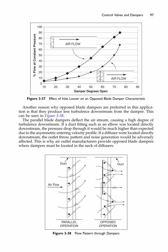
0
10
20
30
40
50
60
70
80
90
100
10 20 30 40 50 60 70 80 90Damper Degrees Open
% F
low
at
Co
nst
ant
Pre
ssu
re
AIR FLOW
AIR FLOW
Figure 3-37 Effect of Inlet Louver on an Opposed Blade Damper Characteristic
97Control Valves and Dampers
Another reason why opposed blade dampers are preferred in this applica-tion is that they produce less turbulence downstream from the damper. Thiscan be seen in Figure 3-38.The parallel blade dampers deflect the air stream, causing a high degree of
turbulence downstream. If a duct fitting such as an elbow was located directlydownstream, the pressure drop through it would be much higher than expecteddue to the asymmetric entering velocity profile. If a diffuser were located directlydownstream, the outlet throw pattern and noise generation would be adverselyaffected. This is why air outlet manufacturers provide opposed blade damperswhere dampers must be located in the neck of diffusers.
PARALLELOPERATION
Air Flow
Duct Duct
OPPOSEDOPERATION
Figure 3-38 Flow Pattern through Dampers
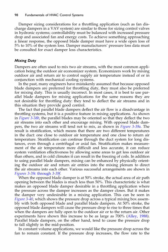
98 Fundamentals of HVAC Control Systems
Damper sizing considerations for a throttling application (such as fan dis-charge dampers in a VAV system) are similar to those for sizing control valvesin hydronic systems; controllability must be balanced with increased pressuredrop and associated fan and energy costs. To achieve something approachinga linear response, the opposed blade damper must have a wide open loss of5% to 10% of the system loss. Damper manufacturers’ pressure loss data mustbe consulted for exact damper loss characteristics.
Mixing Duty
Dampers are often used to mix two air streams, with the most common appli-cation being the outdoor air economizer system. Economizers work by mixingoutdoor air and return air to control supply air temperature instead of or inconjunction with mechanical cooling systems.
In the past, many engineers have mistakenly assumed that because opposedblade dampers are preferred for throttling duty, they must also be preferredfor mixing duty. This is usually incorrect. In most cases, it is best to use par-allel blade dampers for mixing applications for the same reasons they arenot desirable for throttling duty: they tend to deflect the air streams and inthis situation they provide good control.
The fact that parallel blade dampers deflect the air flow is a disadvantage inthrottling systems, but it is a positive feature in mixing applications. As shownin Figure 3-38b, the parallel blades may be oriented so that they deflect the twoair streams into each other and encourage mixing. With opposed blade dam-pers, the two air streams will tend not to mix, as shown in Figure 3-39a. Theresult is stratification, which means that there are two different temperaturesin the duct: one close to outdoor air temperature and one close to return airtemperature. Stratification can continue through the duct system for long dis-tances, even through a centrifugal or axial fan. Stratification makes measure-ment of the air temperature more difficult and less accurate, it can reducesystem ventilation effectiveness by allowing some areas to get less outdoor airthan others, and in cold climates it can result in the freezing of coils. In additionto using parallel blade dampers, mixing can be enhanced by physically orient-ing the outdoor air and return air entries into the mixing plenum to directthe air streams into each other. Various successful arrangements are shown inFigures 3-39c through 3-39f.
When the opposed blade damper is at 50% stroke, the actual area of air pathopening between the blades is much less than 50%. This characteristic is whatmakes an opposed blade damper desirable in a throttling application wherethe pressure across the damper increases as the damper closes. But it makesthe damper very undesirable in a mixing application. This can be seen inFigure 3-40, which shows the pressure drop across a typical mixing box assem-bly with both opposed blade and parallel blade dampers. At 50% stroke, theopposed blade dampers will cause the pressure drop to rise to three times thatwhen the dampers are fully open to the outdoor air or to the return air. Otherexperiments have shown this increase to be as large as 700% (Alley, 1988).Parallel blade dampers, on the other hand, tend to cause the pressure dropto fall slightly in the mid-position.
In constant volume applications, we would like the pressure drop across thefan to remain constant. If the pressure drop increases, the flow rate to the
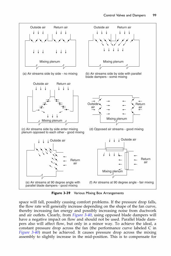
Outside air Return air
Outside air
Outside air Outside air
Outsideair
Return air
Returnair
Returnair
Returnair
Mixing plenum
Mixing plenum
Outside air Return air
Mixing plenum
Mixing plenum
Mixing plenum
(a) Air streams side by side - no mixing
(c) Air streams side by side enter mixingplenum opposed to each other - good mixing
(d) Opposed air streams - good mixing
(e) Air streams at 90 degree angle withparallel blade dampers - good mixing
(f) Air streams at 90 degree angle - fair mixing
(b) Air streams side by side with parallelbiade dampers - some mixing
Figure 3-39 Various Mixing Box Arrangements
99Control Valves and Dampers
space will fall, possibly causing comfort problems. If the pressure drop falls,the flow rate will generally increase depending on the shape of the fan curve,thereby increasing fan energy and possibly increasing noise from ductworkand air outlets. Clearly, from Figure 3-40, using opposed blade dampers willhave a negative impact on flow and should not be used. Parallel blade dam-pers also will affect flow, but only in a minor way. To achieve the ideal, aconstant pressure drop across the fan (the performance curve labeled C inFigure 3-40) must be achieved. It causes pressure drop across the mixingassembly to slightly increase in the mid-position. This is to compensate for
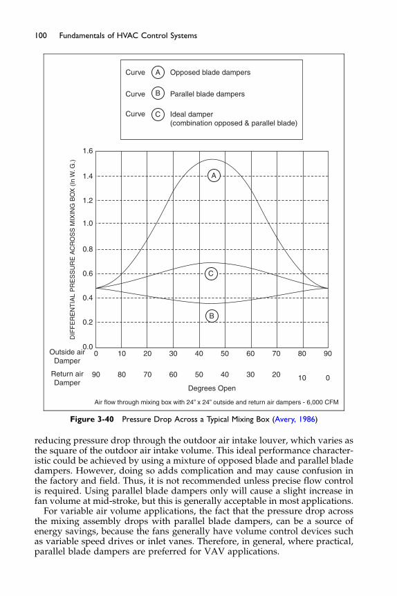
Curve Opposed blade dampers
Parallel blade dampers
Ideal damper(combination opposed & parallel blade)
A
Curve
Curve
1.6
1.4
1.2
1.0
0.8
0.6
0.4
0.2
0.00Outside air
Damper
DIF
FE
RE
NT
IAL
PR
ES
SU
RE
AC
RO
SS
MIX
ING
BO
X (
In W
. G.)
Return airDamper
0
10
10
20
20
30
30
40
40
50
Degrees Open
Air flow through mixing box with 24” x 24” outside and return air dampers - 6,000 CFM
50
60
60
70
70
80
80
90
90
B
B
C
A
C
Figure 3-40 Pressure Drop Across a Typical Mixing Box (Avery, 1986)
100 Fundamentals of HVAC Control Systems
reducing pressure drop through the outdoor air intake louver, which varies asthe square of the outdoor air intake volume. This ideal performance character-istic could be achieved by using a mixture of opposed blade and parallel bladedampers. However, doing so adds complication and may cause confusion inthe factory and field. Thus, it is not recommended unless precise flow controlis required. Using parallel blade dampers only will cause a slight increase infan volume at mid-stroke, but this is generally acceptable in most applications.
For variable air volume applications, the fact that the pressure drop acrossthe mixing assembly drops with parallel blade dampers, can be a source ofenergy savings, because the fans generally have volume control devices suchas variable speed drives or inlet vanes. Therefore, in general, where practical,parallel blade dampers are preferred for VAV applications.
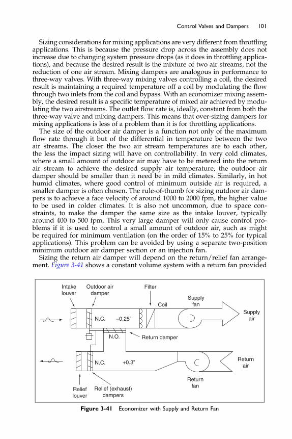
101Control Valves and Dampers
Sizing considerations for mixing applications are very different from throttlingapplications. This is because the pressure drop across the assembly does notincrease due to changing system pressure drops (as it does in throttling applica-tions), and because the desired result is the mixture of two air streams, not thereduction of one air stream. Mixing dampers are analogous in performance tothree-way valves. With three-way mixing valves controlling a coil, the desiredresult is maintaining a required temperature off a coil by modulating the flowthrough two inlets from the coil and bypass. With an economizer mixing assem-bly, the desired result is a specific temperature of mixed air achieved by modu-lating the two airstreams. The outlet flow rate is, ideally, constant from both thethree-way valve and mixing dampers. This means that over-sizing dampers formixing applications is less of a problem than it is for throttling applications.The size of the outdoor air damper is a function not only of the maximum
flow rate through it but of the differential in temperature between the twoair streams. The closer the two air stream temperatures are to each other,the less the impact sizing will have on controllability. In very cold climates,where a small amount of outdoor air may have to be metered into the returnair stream to achieve the desired supply air temperature, the outdoor airdamper should be smaller than it need be in mild climates. Similarly, in hothumid climates, where good control of minimum outside air is required, asmaller damper is often chosen. The rule-of-thumb for sizing outdoor air dam-pers is to achieve a face velocity of around 1000 to 2000 fpm, the higher valueto be used in colder climates. It is also not uncommon, due to space con-straints, to make the damper the same size as the intake louver, typicallyaround 400 to 500 fpm. This very large damper will only cause control pro-blems if it is used to control a small amount of outdoor air, such as mightbe required for minimum ventilation (on the order of 15% to 25% for typicalapplications). This problem can be avoided by using a separate two-positionminimum outdoor air damper section or an injection fan.Sizing the return air damper will depend on the return/relief fan arrange-
ment. Figure 3-41 shows a constant volume system with a return fan provided
Intakelouver
N.C.
N.C.
N.O.
−0.25”
+0.3”
Outdoor airdamper
Filter
CoilSupply
fanSupply
air
Returnair
Returnfan
Return damper
Relieflouver
Relief (exhaust)dampers
Figure 3-41 Economizer with Supply and Return Fan
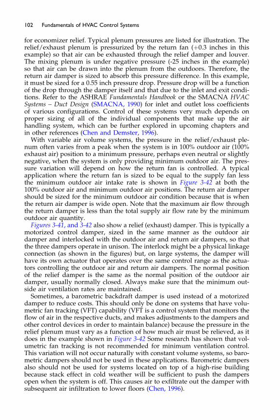
102 Fundamentals of HVAC Control Systems
for economizer relief. Typical plenum pressures are listed for illustration. Therelief/exhaust plenum is pressurized by the return fan (þ0.3 inches in thisexample) so that air can be exhausted through the relief damper and louver.The mixing plenum is under negative pressure (-25 inches in the example)so that air can be drawn into the plenum from the outdoors. Therefore, thereturn air damper is sized to absorb this pressure difference. In this example,it must be sized for a 0.55 inch pressure drop. Pressure drop will be a functionof the drop through the damper itself and that due to the inlet and exit condi-tions. Refer to the ASHRAE Fundamentals Handbook or the SMACNA HVACSystems – Duct Design (SMACNA, 1990) for inlet and outlet loss coefficientsof various configurations. Control of these systems very much depends onproper sizing of all of the individual components that make up the airhandling system, which can be further explored in upcoming chapters andin other references (Chen and Demster, 1996).
With variable air volume systems, the pressure in the relief/exhaust ple-num often varies from a peak when the system is in 100% outdoor air (100%exhaust air) position to a minimum pressure, perhaps even neutral or slightlynegative, when the system is only providing minimum outdoor air. The pres-sure variation will depend on how the return fan is controlled. A typicalapplication where the return fan is sized to be equal to the supply fan lessthe minimum outdoor air intake rate is shown in Figure 3-42 at both the100% outdoor air and minimum outdoor air positions. The return air dampershould be sized for the minimum outdoor air condition because that is whenthe return air damper is wide open. Note that the maximum air flow throughthe return damper is less than the total supply air flow rate by the minimumoutdoor air quantity.
Figures 3-41, and 3-42 also show a relief (exhaust) damper. This is typically amotorized control damper, sized in the same manner as the outdoor airdamper and interlocked with the outdoor air and return air dampers, so thatthe three dampers operate in unison. The interlock might be a physical linkageconnection (as shown in the figures) but, on large systems, the damper willhave its own actuator that operates over the same control range as the actua-tors controlling the outdoor air and return air dampers. The normal positionof the relief damper is the same as the normal position of the outdoor airdamper, usually normally closed. Always make sure that the minimum out-side air ventilation rates are maintained.
Sometimes, a barometric backdraft damper is used instead of a motorizeddamper to reduce costs. This should only be done on systems that have volu-metric fan tracking (VFT) capability (VFT is a control system that monitors theflow of air in the respective ducts, and makes adjustments to the dampers andother control devices in order to maintain balance) because the pressure in therelief plenum must vary as a function of how much air must be relieved, as itdoes in the example shown in Figure 3-42 Some research has shown that vol-umetric fan tracking is not recommended for minimum ventilation control.This variation will not occur naturally with constant volume systems, so baro-metric dampers should not be used in these applications. Barometric dampersalso should not be used for systems located on top of a high-rise buildingbecause stack effect in cold weather will be sufficient to push the dampersopen when the system is off. This causes air to exfiltrate out the damper withsubsequent air infiltration to lower floors (Chen, 1996).
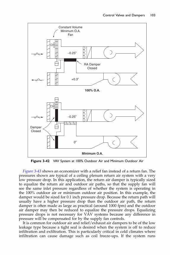
100% O.A.
Minimum O.A.
DamperClosed
Constant VolumeMinimum O.A.
Fan
RA DamperClosed
+0.3”
0”
−0.25”
−0.25”
Figure 3-42 VAV System at 100% Outdoor Air and Minimum Outdoor Air
103Control Valves and Dampers
Figure 3-43 shows an economizer with a relief fan instead of a return fan. Thepressures shown are typical of a ceiling plenum return air system with a verylow pressure drop. In this application, the return air damper is typically sizedto equalize the return air and outdoor air paths, so that the supply fan willsee the same inlet pressure regardless of whether the system is operating inthe 100% outdoor air or minimum outdoor air position. In this example, thedamper would be sized for 0.1 inch pressure drop. Because the return path willusually have a higher pressure drop than the outdoor air path, the returndamper is often made as large as practical (around 1000 fpm) and the outdoorair damper may then be reduced to equalize the pressure drops. Equalizingpressure drops is not necessary for VAV systems because any difference inpressure will be compensated for by the supply fan controls.It is common for outdoor air and relief/exhaust air dampers to be of the low
leakage type because a tight seal is desired when the system is off to reduceinfiltration and exfiltration. This is particularly critical in cold climates whereinfiltration can cause damage such as coil freeze-ups. If the system runs
−0.2”
−0.3”Q.A.
Relieffan
Figure 3-43 Economizer with Relief Fan
104 Fundamentals of HVAC Control Systems
continuously (as it might in an institutional or manufacturing application),outdoor air leakage is not usually critical because a minimum outdoor airintake is typically required at all times for ventilation.
Often overlooked is the need to minimize leakage through the return airdamper. When the system operates on 100% outdoor air, as it will when theoutdoor air temperature is between the desired cooling supply air tempera-ture set point and the economizer high limit condition, any leakage of returnair into the mixing plenum will increase cooling energy usage. Therefore, alow leakage return air damper should be used for all economizer applications.
For more detailed information and worked examples on these damperarrangements see the ASHRAE Guideline 16-2003 Selecting Outdoor, Return,and Relief Dampers for Air-Side Economizer Systems.
The Next Step
In the next chapter, we will learn about sensors used to measure the con-trolled variable. Sensors commonly used in HVAC applications measure tem-perature, moisture content in air, differential pressure, flow, and current.
Bibliography
Alley, R. (1988) “Selecting and sizing outside and return air dampers for VAV econo-mizer systems.” ASHRAE Transactions. ASHRAE. Vol. 94, Pt. 1, pp. 1457–1466.
AMCA International 500-D, Laboratory Methods of Testing Dampers for Rating. ArlingtonHeights, IL: Air Movement and Control Association International, Inc.
ANSI/ASHRAE/IESNA Standard 90.1-2004 (2004) Energy Standard for Buildings ExceptLow-rise Residential Buildings. Atlanta, GA: American Society of Heating, Refrigerat-ing and Air-conditioning Engineers, Inc.
ASHRAE Guideline 16-2003 (2003) Selecting Outdoor, Return, and Relief Dampers for Air-side Economizer Systems. Atlanta, GA: American Society of Heating, Refrigeratingand Air-conditioning Engineers, Inc.
ASHRAE Handbooks:Fundamentals 2005 – Fundamentals of ControlsHVAC Systems and Equipment 2004 – ValvesHVAC Applications 2007 – Testing, Adjusting, and Balancing.
105Control Valves and Dampers
ASHRAE (2004) Research Report (RP-1157) Flow Resistance and Modulating Charac-teristics of Control Dampers.
Avery, G. (1986) “VAV: an outside air economizer cycle.” ASHRAE Journal. Vol. 28, No.12, pp. 26–30.
Chen, S. and Demster, S. (1996) Variable Air Volume Systems for Environmental Quality.New York: McGraw-Hill. Chapter 5.
Hegberg, R. (1997) “Selecting control and balancing valves in a variable flow system.”ASHRAE Journal. Vol. 39, No. 6, pp. 53–62.
Hegberg, R. (2001–2002) Various Presentations from the Little Red Schoolhouse. Chicago,IL: Bell and Gossett.
SMACNA. 1990. HVAC Systems – Duct Design. Chantilly, VA: Sheet Metal and Air Con-ditioning Contractors’ National Association.

Chapter 4
Sensors and Auxiliary Devices
Contents of Chapter 4
Study Objectives of Chapter 44.1 Introduction to Terms
4.2 Temperature Sensors 4.3 Humidity and the Psychrometric Chart 4.4 Moisture Sensors 4.5 Pressure Sensors 4.6 Flow Sensors and Meters 4.7 Auxiliary Devices The Next StepBibliographyStudy Objectives of Chapter 4
Sensors are used to measure the controlled variable. Without measurement,there can be no control. Sensors are also used for monitoring purposes to keepthe operator informed about elements in the system that indicate proper (orimproper) operation. Sensors commonly used in HVAC applications includetemperature, Carbon Dioxide (CO2), Carbon Monoxide (CO), relative humid-ity, dewpoint, differential pressure, sensors used to estimate indoor air quality(IAQ), and velocity/flow sensors.
After studying this chapter, you should:
Be familiar with common temperature sensing devices.Understand the psychrometric chart and moisture measurement in air.Understand how moisture is measured and the effects of temperature on
the measurement.Understand how differential pressure is sensed.Be aware of some of the sensors used for the estimation of IAQ.Understand about different types of air and water flow sensors, and the
HVAC applications for which they are best suited.Become familiar with auxiliary devices common to control systems.

107Sensors and Auxiliary Devices
Note that sensing technology is a rapidly changing field. Many of the phys-ical sensors used in the past are being replaced by small electric/electronicdevices which provide a vast array of qualities, reliabilities, and costs. Themost common devices used in HVAC applications at the time of this publi-cation are described below, but other devices are being used and new sensortechnologies are being developed all the time. Manufacturers’ catalogs andrepresentatives should be consulted for the latest options. Remember thatthe latest may, or may not, be the best initial value or the best long-term value.
4.1 Introduction to Terms
We are going to start this chapter with some general discussion about terms,their use, and their definitions. Each definition is taken [B[from the ASHRAETerminology of Heating, Ventilating, Air Conditioning, and Refrigeration (1991).You are not expected to learn them but rather to understand what they meanand how they are very important in some situations and not in others.
Accuracy
1. Conformity of an indicated value to an accepted standard value, or truevalue. Quantitatively, it should be expressed as an error or an uncertainty.The property is the joint effect of method, observer, apparatus, and envi-ronment. Accuracy is impaired by mistakes, by systematic bias such asabnormal ambient temperature, or by random errors (imprecision).
2. Degree of freedom from error, that is, the degree of conformity to truthor to a rule. Accuracy is contrasted with precision, e.g., four-placenumbers are less precise than six-place numbers; nevertheless a properlycomputed four-place number might be more accurate than an improp-erly computed six-place number.
3. Ability of an instrument to indicate the true value of a measured physicalquantity.
The fundamental issue with accuracy is “How true is the value?”Note the issue of apparent numerical accuracy and real accuracy. For exam-
ple, compare a thermometer that provides readings in 1�F. If this thermometeris just 1�F in error it will provide more accurate readings than a thermome-ter that reads to 0.1�F which is 2�F out of true. In general, the number of digitsis not a certain indication of accuracy. Accuracy is particularly important wheresensors are replaced without field adjustment.
Range
1. Difference between the highest and the lowest operational values, suchas pressure, temperature, rate of flow, or computer values.
2. Region between limits within which a quantity is measured, transmitted,or received, expressed by stating the lower and upper range values.
A sensor has a range of operation that is stated by the manufacturer. In gen-eral, one should avoid choosing sensors that will have to operate close toeither end of their range.
108 Fundamentals of HVAC Control Systems
Reliability
1. Mathematical probability that a device will perform its objective ade-quately for the period of time intended under the operating conditionsspecified.
2. Probability that a device will function without failure over a specifiedtime period or amount of usage.
3. Probability that an instrument’s repeatability and accuracy will continueto fall within specified limits.
Note that reliability covers two issues. First, “will it keep on working?” –what is the expected life. Second is “will it keep on working the same tothe same standards over time?” To deal with significant drift over time oneneeds a maintenance system capable of regular checks on performance andof recalibrating the device.
Repeatability, Precision
1. Closeness of agreement among repeated measurements of the samevariable under the same conditions.
2. Closeness of agreement among consecutive measurements of the outputfor the same value of input approaching from the same direction.
Repeatability covers the issue of getting the same reading under the same cir-cumstances. You may have noticed the words “approaching from the samedirection.” This is more significant with some sensors than others. An exampleof this from an earlier chapter is the proportional controller which will have anoffset in one direction in cooling mode and the opposite direction in heatingmode.
Transmitter
A device that accepts a signal and transmits the information in the signal in adifferent form to another device. In many of the devices discussed in thischapter the transmitter measures a change in resistance and, based on builtin linear, or non-linear, rules outputs signal proportional to the change inmeasured variable. This signal normally conforms to a 0–5 volt, 0–10 volt,or 4–20 milliamp (mA) signal. The voltage outputs work well for HVAC.The 4–20 mA signal is more robust, particularly for long cable lengths, andis largely used in industrial situations.
The accuracy of measurement is the combined accuracy of sensor andtransmitter.
Figure 4-1 (Hegberg, 2001–2002) depicts a sensor which is precise and inac-curate, and a sensor that is imprecise and relatively accurate. The sensor thatis precise and inaccurate provides an output with a permanent offset from thetrue value. Its smooth performance can give one a sense of “accuracy” that isunjustified. On the other hand, the imprecise and accurate unit jogs around ina most inconsistent manner, although it is providing a much closer-to-truevalue. The preference is always for the most precise and accurate sensorchoices that the budget allows.

Precise, inaccurate
Actual reading
Imprecise, accurate
TIME
TE
MP
ER
AT
UR
EFigure 4-1 Accuracy and Precision (Hegberg, 2001–2002)
109Sensors and Auxiliary Devices
As of late, interchangeability and interoperability of sensors with differingmanufacturers’ control systems is becoming a more and more important fea-ture to be considered in the buying and specifying process. Interchangeabilitydeals with the ability to physically replace a sensor from one manufacturerwith a sensor from another manufacturer, and have them read the samevalues. Interoperability deals with communication between the sensor andthe system to which it is connected. A very simple example: there are stan-dards for passing an electrical signal from sensor to system, 0–10 volts and4–20 mA. One cannot simply replace a 0–10 volt unit with a 4–20 mA unit.When we get into direct digital controls (DDC) later in the course the issueof interoperability becomes very important as there are many communicationsprotocols by which devices communicate with systems.In order to specify and design sensor systems, evaluation of “first cost” effec-
tiveness such as qualitative items like installation time, accuracy, precision,reliability, repeatability, durability, maintenance, repair/replacement costs,compatibility, etc., should be considered. In too many cases in everydaypractice, first costs often overwhelm the buying decision.
4.2 Temperature Sensors
In air-conditioning applications, temperature is typically the primary controlledvariable. In comfort HVAC applications, temperature is used as the surrogatefor human comfort because it is typically the primary factor affecting comfort.Other factors (such as humidity, air velocity, and radiant temperature) also affectcomfort, but usually in a less significant way. Accordingly, these secondary fac-tors are seldom directly measured and controlled, although they are generallyindirectly controlled via the design of the HVAC system (in the case of humidityand air velocity), and building envelope (in the case of radiant temperature).Temperature sensors can be categorized by the effect used to generate the
temperature-versus-signal response:
Bimetal
Probably the first temperature sensor used for automatic control purposeswas the bimetallic sensor (or bimetal for short), as shown in Figure 4-2.This consists of two metal strips joined together continuously by welding or
other means. Themetals are selected so that each has a very different coefficient
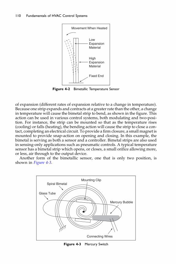
LowExpansionMaterial
Movement When Heated
HighExpansionMaterial
Fixed End
Figure 4-2 Bimetallic Temperature Sensor
110 Fundamentals of HVAC Control Systems
of expansion (different rates of expansion relative to a change in temperature).Because one strip expands and contracts at a greater rate than the other, a changein temperature will cause the bimetal strip to bend, as shown in the figure. Thisaction can be used in various control systems, both modulating and two-posi-tion. For instance, the strip can be mounted so that as the temperature rises(cooling) or falls (heating), the bending action will cause the strip to close a con-tact, completing an electrical circuit. To provide a firm closure, a small magnet ismounted to provide snap-action on opening and closing. In this example, thebimetal is serving as both a sensor and a controller. Bimetal strips are also usedin sensing-only applications such as pneumatic controls. A typical temperaturesensor has a bimetal strip which opens, or closes, a small orifice allowing more,or less, air through to the output device.
Another form of the bimetallic sensor, one that is only two position, isshown in Figure 4-3.
Mounting Clip
Connecting Wires
Mercury Bubble
Spiral Bimetal
Glass Tube
Figure 4-3 Mercury Switch
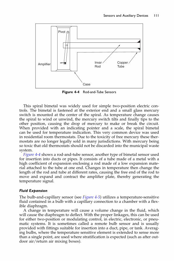
Amplifier
Pivot
InvarRod
Case
CopperTube
Figure 4-4 Rod-and-Tube Sensors
111Sensors and Auxiliary Devices
This spiral bimetal was widely used for simple two-position electric con-trols. The bimetal is fastened at the exterior end and a small glass mercuryswitch is mounted at the center of the spiral. As temperature change causesthe spiral to wind or unwind, the mercury switch tilts and finally tips to theother position, causing the drop of mercury to make or break the circuit.When provided with an indicating pointer and a scale, the spiral bimetalcan be used for temperature indication. This very common device was usedin residential room thermostats. Due to the toxicity of free mercury these ther-mostats are no longer legally sold in many jurisdictions. With mercury beingso toxic that old thermostats should not be discarded into the municipal wastesystem.Figure 4-4 shows a rod-and-tube sensor, another type of bimetal sensor used
for insertion into ducts or pipes. It consists of a tube made of a metal with ahigh coefficient of expansion enclosing a rod made of a low expansion mate-rial attached to the tube at one end. Changes in temperature then change thelength of the rod and tube at different rates, causing the free end of the rod tomove and expand and contract the amplifier plate, thereby generating thetemperature signal.
Fluid Expansion
The bulb-and-capillary sensor (see Figure 4-5) utilizes a temperature-sensitivefluid contained in a bulb with a capillary connection to a chamber with a flex-ible diaphragm.A change in temperature will cause a volume change in the fluid, which
will cause the diaphragm to deflect. With the proper linkages, this can be usedfor either two-position or modulating control, in electric, electronic, or pneu-matic systems. It is sometimes called a remote bulb sensor and is usuallyprovided with fittings suitable for insertion into a duct, pipe, or tank. Averag-ing bulbs, where the temperature sensitive element is extended to sense morethan a single point, are used where stratification is expected (such as after out-door air/return air mixing boxes).

Bulb Capillary Diaphragm
Post
Spring
Figure 4-5 Capillary Sensors
112 Fundamentals of HVAC Control Systems
Capillaries can be made to be temperature compensated to minimize theeffect of the atmosphere through which the capillary passes. This is done byusing two dissimilar metals for the capillary, one on the outside (usually stain-less steel) and another metal on the inside, with the sensing fluid in between.The materials are selected so that the differential coefficient of expansion ofthe two metals exactly equals the coefficient of expansion of the sensing fluid.Thus, as the capillary expands and contracts due to changes in ambient tem-peratures, it makes room for the fluid as it expands and contracts at the samerate. In this way, the ambient temperature changes do not affect the fluidpressure signal.
Mill
ivol
ts
0
20
40
60
80
1000°F 2000°F
Temperature °F
K
E
Figure 4-6 Thermocouples, E, and K characteristics
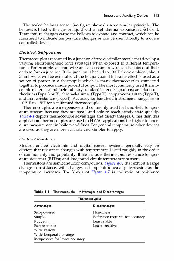
113Sensors and Auxiliary Devices
The sealed bellows sensor (no figure shown) uses a similar principle. Thebellows is filled with a gas or liquid with a high thermal expansion coefficient.Temperature changes cause the bellows to expand and contract, which can bemeasured to indicate temperature changes or can be used directly to move acontrolled device.
Electrical, Self-powered
Thermocouples are formed by a junction of two dissimilarmetals that develop avarying electromagnetic force (voltage) when exposed to different tempera-tures. For example, an iron wire and a constantan wire can be joined at theirends to form a junction. If the junction is heated to 100�F above ambient, about3 milli-volts will be generated at the hot junction. This same effect is used as asource of power in a thermopile which is many thermocouples connectedtogether to produce amore powerful output. Themost commonly used thermo-couple materials (and their industry standard letter designations) are platinum-rhodium (Type S or R), chromel-alumel (Type K), copper-constantan (Type T),and iron-constantan (Type J). Accuracy for handheld instruments ranges from�0.5�F to �5�F for a calibrated thermocouple.Thermocouples are inexpensive and commonly used for hand-held temper-
ature sensors because they are small and able to reach steady-state quickly.Table 4-1 depicts thermocouple advantages and disadvantages. Other than thisapplication, thermocouples are used in HVAC applications for higher temper-ature measurement in boilers and flues. For general temperature other devicesare used as they are more accurate and simpler to apply.
Electrical Resistance
Modern analog electronic and digital control systems generally rely ondevices that resistance changes with temperature. Listed roughly in the orderof commonality and popularity, these include: thermistors; resistance temper-ature detectors (RTDs); and integrated circuit temperature sensors.Thermistors are semiconductor compounds, Figure 4-7, that exhibit a large
change in resistance, with changes in temperature usually decreasing as thetemperature increases. The Y-axis of Figure 4-7 is the ratio of resistance
Table 4-1 Thermocouple – Advantages and Disadvantages
Thermocouples
Advantages Disadvantages
Self-powered Non-linearSimple Reference required for accuracyRugged Least stableFast response Least sensitiveWide varietyWide temperature rangeInexpensive for lower accuracy
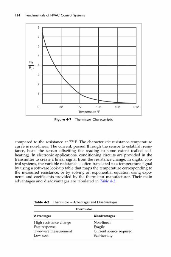
0
1
2
3
RT
R774
5
6
7
8
32 77
Temperature �F
105 122 212
Figure 4-7 Thermistor Characteristic
114 Fundamentals of HVAC Control Systems
compared to the resistance at 77�F. The characteristic resistance-temperaturecurve is non-linear. The current, passed through the sensor to establish resis-tance, heats the sensor offsetting the reading to some extent (called self-heating). In electronic applications, conditioning circuits are provided in thetransmitter to create a linear signal from the resistance change. In digital con-trol systems, the variable resistance is often translated to a temperature signalby using a software look-up table that maps the temperature corresponding tothe measured resistance, or by solving an exponential equation using expo-nents and coefficients provided by the thermistor manufacturer. Their mainadvantages and disadvantages are tabulated in Table 4-2.
Table 4-2 Thermistor – Advantages and Disadvantages
Thermistor
Advantages Disadvantages
High resistance change Non-linearFast response FragileTwo-wire measurement Current source requiredLow cost Self-heating

115Sensors and Auxiliary Devices
Thermistors typically have an accuracy around �0.5�F, but they can be asaccurate as�0.2�F. They have a high sensitivity, in other words they have a fastand detailed response to a change in temperature. However, they drift overtime, and regular calibration is required to maintain this accuracy. At one time,calibration was required about every six months or so, but the quality of ther-mistors has improved in recent years, reducing the frequency interval to onceevery five years or more. For instance, commercial grade thermistors are nowavailable with a guaranteed maximum drift of 0.05�F over a five-year period.They now have long-term stability, and a fast response, at a low cost.The RTD is another of the most commonly used temperature sensor in ana-
log electronic and digital control systems because it is very stable and accu-rate, and advances in manufacturing techniques have rapidly brought pricesdown. As the name implies, the RTD is constructed of a metal that has a resis-tance variation as a direct acting function of temperature that is linear over therange of application, Figure 4-8. Common materials include platinum, copper-nickel, copper, tungsten, and some nickel-iron alloys. In HVAC applications,RTDs are often in a wound wire configuration, with the RTD metal formedinto a fine wire and wrapped around a core. Coil wound RTDs cost more thanthermistors but they are more stable, so regular recalibration is not usuallyrequired. Standard platinum RTDs have a reference resistance of 100 ohmsat 0�C. This low resistance (compared to 10,000 ohms to 100,000 ohms forthermistors) typically requires that the measurement circuit compensatefor or eliminate the resistance of the wiring used to connect the RTD to thedetector, because this resistance will be on the same order of magnitude asthe RTD. To do this, either the detector must be calibrated to compensate
0
1
2
3
RT
R774
Thermistor
RTD
5
6
7
8
32 77
Temperature �F
105 122 212
Figure 4-8 Thermistor and RTD Resistance Change with Temperature

116 Fundamentals of HVAC Control Systems
for wiring resistance or, more commonly, three-wire or four-wire circuits areused that balance or eliminate wiring resistance. For HVAC applications, plat-inum RTDs rated at 100 ohms are typically about �0.5�F at the calibrationpoint to �1.0�F accuracy over the application range. However, high purityplatinum sensors can have an accuracy of �0.02�F or even better.
A recent development is the thin-film platinum RTD, which has a referenceresistance of about 1,000 ohms. Made by deposition techniques that substan-tially reduce the cost, these sensors are one of the primary reasons why RTDsbegan to replace thermistors in electronic and digital control systems. Thin-film RTDs have accuracies on the order of �0.5�F to �1.0�F at their calibrationpoint. As the units are dependent on the behavior of platinum metal they havea very, very low drift. The main advantages and disadvantages of RTDs areshown in Table 4-3.
Integrated circuit (IC) temperature sensors (also called solid-state tempera-ture sensors or linear diodes) are based on semiconductor diodes and transis-tors that exhibit reproducible temperature dependence. They are typicallysold as ready-made, packaged integrated circuits (sensor and transmitter)with built-in conditioning to produce a linear resistance to temperature signal.Solid-state sensors have the advantage of requiring no calibration, and theircost and accuracy are on the order of thin-film platinum RTDs. See Table 4-4for their main advantages and disadvantages.
The process to select an appropriate sensor type should be concerned withthe economics, accuracy, and long-term reliability of the sensor. A summaryof sensor characteristics is shown in Table 4-5. In HVAC systems, for the
Table 4-4 Linear Diodes – Advantages and Disadvantages
Linear Diodes
Advantages Disadvantages
Most linear Use up to 330�FInexpensive Power supply required
SlowSelf-heatingLimited configurations
Table 4-3 RTD – Advantages and Disadvantages
RTDs
Advantages Disadvantages
Most stable ExpensiveMost accurate Current source requiredMost linear Coiled type low resistance, 100 ohms,
requires good temperature compensationFilm type has relatively low resistanceSelf-heating
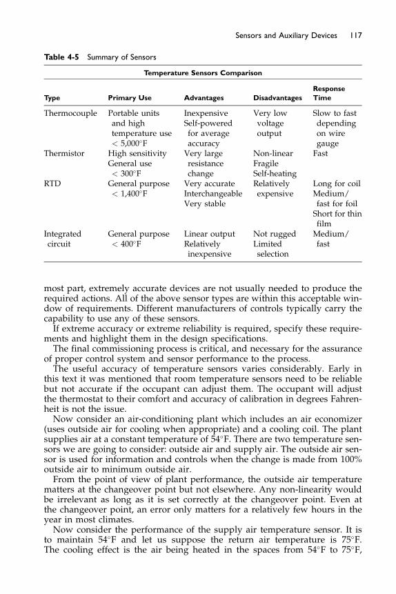
Table 4-5 Summary of Sensors
Temperature Sensors Comparison
Type Primary Use Advantages Disadvantages
Response
Time
Thermocouple Portable unitsand hightemperature use< 5,000�F
InexpensiveSelf-poweredfor averageaccuracy
Very lowvoltageoutput
Slow to fastdependingon wiregauge
Thermistor High sensitivityGeneral use< 300�F
Very largeresistancechange
Non-linearFragileSelf-heating
Fast
RTD General purpose< 1,400�F
Very accurateInterchangeableVery stable
Relativelyexpensive
Long for coilMedium/fast for foilShort for thinfilm
Integratedcircuit
General purpose< 400�F
Linear outputRelativelyinexpensive
Not ruggedLimitedselection
Medium/fast
117Sensors and Auxiliary Devices
most part, extremely accurate devices are not usually needed to produce therequired actions. All of the above sensor types are within this acceptable win-dow of requirements. Different manufacturers of controls typically carry thecapability to use any of these sensors.If extreme accuracy or extreme reliability is required, specify these require-
ments and highlight them in the design specifications.The final commissioning process is critical, and necessary for the assurance
of proper control system and sensor performance to the process.The useful accuracy of temperature sensors varies considerably. Early in
this text it was mentioned that room temperature sensors need to be reliablebut not accurate if the occupant can adjust them. The occupant will adjustthe thermostat to their comfort and accuracy of calibration in degrees Fahren-heit is not the issue.Now consider an air-conditioning plant which includes an air economizer
(uses outside air for cooling when appropriate) and a cooling coil. The plantsupplies air at a constant temperature of 54�F. There are two temperature sen-sors we are going to consider: outside air and supply air. The outside air sen-sor is used for information and controls when the change is made from 100%outside air to minimum outside air.From the point of view of plant performance, the outside air temperature
matters at the changeover point but not elsewhere. Any non-linearity wouldbe irrelevant as long as it is set correctly at the changeover point. Even atthe changeover point, an error only matters for a relatively few hours in theyear in most climates.Now consider the performance of the supply air temperature sensor. It is
to maintain 54�F and let us suppose the return air temperature is 75�F.The cooling effect is the air being heated in the spaces from 54�F to 75�F,
118 Fundamentals of HVAC Control Systems
a temperature rise of 21�F. Now let us suppose the temperature sensor is just1�F off and the supply temperature is 55�F. The cooling capacity is down from55�F to 75�F, or 20�F, a drop of 5% in cooling capacity. An error of 2�F pro-duces a reduction of 10%. Accuracy really does matter here. However, theaccuracy is only needed at 54�F not at higher or lower temperatures.
This issue of accuracy is particularly important where sensors are replacedwithout site calibration. A higher supplied accuracy is needed in this change-it-out situation without site calibration.
4.3 Humidity and the Psychrometric Chart
Humidity is the moisture content in air. Before we consider humidity sensors,it is important that you understand what is being measured, and how the var-ious measurements relating to moisture content and temperature interact.Since moisture and temperature relate to the energy, or enthalpy, of the moistair we will also introduce that issue.
The relationships between temperature, moisture content, and energy aremost easily understood using a visual aid called the “psychrometric chart.”
The psychrometric chart is an industry-standard tool that is used to visua-lize the interrelationships between dry air, moisture, and energy. If you areresponsible for the design or maintenance of any aspect of air-conditioningin buildings, a clear and comfortable understanding of the chart will makeyour job easier.
Initially the chart can be intimidating, but as you work with it you will dis-cover that the relationships that it illustrates are relatively easy to understand.Once you are comfortable with it, you will discover that it is a tool that canmake it easier to troubleshoot air-conditioning problems in buildings. In thiscourse we will only introduce the psychrometric chart, and provide a verybrief overview of its structure.
The psychrometric chart is built upon two simple concepts.
1. Indoor air is a mixture of dry air and water vapor.2. There is a specific amount of energy in the mixture at a specific temper-
ature and pressure.
Indoor Air is a Mixture of Dry Air and Water Vapor
The air we live in is a mixture of both dry air and water vapor. Both are invisiblegases. The water vapor in air is also called moisture or humidity. The quantity ofwater vapor in air is expressed as “pounds of water vapor per pound of air.” Thisratio is called the “humidity ratio,” abbreviation W, and the units are poundsof water/pound of dry air, lbw/lbda, often abbreviated to lb/lb.
The exact properties of moist air vary with pressure. As pressure reduces asaltitude increases the properties of moist air change with altitude. Typically,psychrometric charts are printed based on standard pressure at sea level.For the rest of this section we will consider pressure as constant.
To understand the relationship between water vapor, air, and temperature,we will consider two conditions:
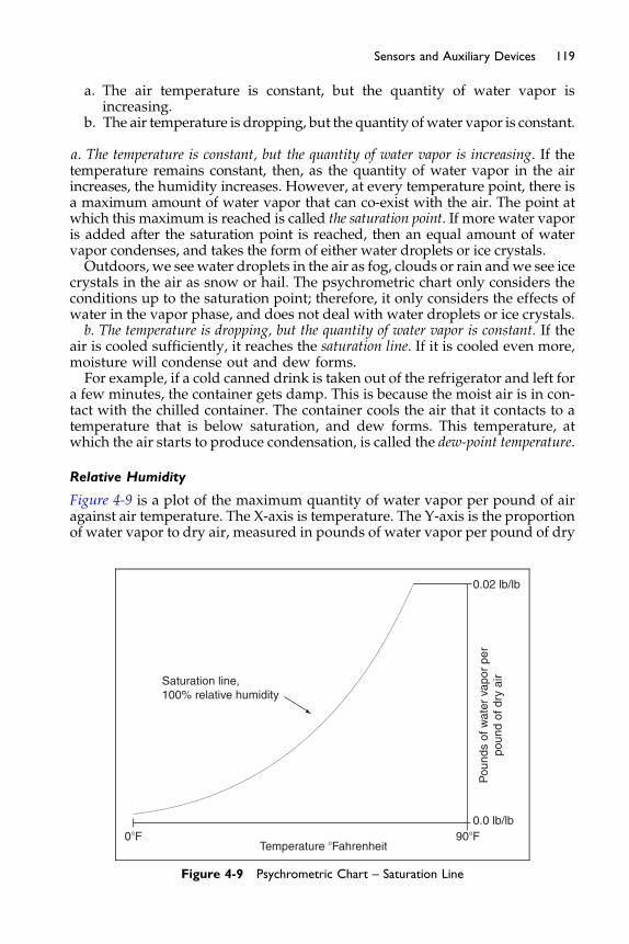
119Sensors and Auxiliary Devices
a. The air temperature is constant, but the quantity of water vapor isincreasing.
b. The air temperature is dropping, but the quantity ofwater vapor is constant.
a. The temperature is constant, but the quantity of water vapor is increasing. If thetemperature remains constant, then, as the quantity of water vapor in the airincreases, the humidity increases. However, at every temperature point, there isa maximum amount of water vapor that can co-exist with the air. The point atwhich this maximum is reached is called the saturation point. If more water vaporis added after the saturation point is reached, then an equal amount of watervapor condenses, and takes the form of either water droplets or ice crystals.Outdoors, we see water droplets in the air as fog, clouds or rain andwe see ice
crystals in the air as snow or hail. The psychrometric chart only considers theconditions up to the saturation point; therefore, it only considers the effects ofwater in the vapor phase, and does not deal with water droplets or ice crystals.b. The temperature is dropping, but the quantity of water vapor is constant. If the
air is cooled sufficiently, it reaches the saturation line. If it is cooled even more,moisture will condense out and dew forms.For example, if a cold canned drink is taken out of the refrigerator and left for
a few minutes, the container gets damp. This is because the moist air is in con-tact with the chilled container. The container cools the air that it contacts to atemperature that is below saturation, and dew forms. This temperature, atwhich the air starts to produce condensation, is called the dew-point temperature.
Relative Humidity
Figure 4-9 is a plot of the maximum quantity of water vapor per pound of airagainst air temperature. The X-axis is temperature. The Y-axis is the proportionof water vapor to dry air, measured in pounds of water vapor per pound of dry
0�F
Saturation line,100% relative humidity
90�F0.0 lb/lb
0.02 lb/lb
Temperature �Fahrenheit
Pou
nds
of w
ater
vap
or p
erpo
und
of d
ry a
ir
Figure 4-9 Psychrometric Chart – Saturation Line
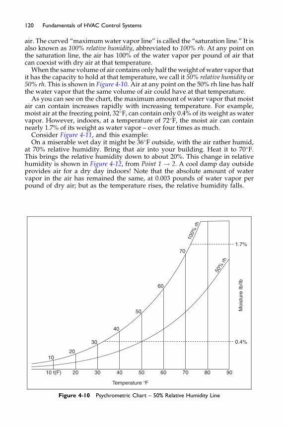
120 Fundamentals of HVAC Control Systems
air. The curved “maximumwater vapor line” is called the “saturation line.” It isalso known as 100% relative humidity, abbreviated to 100% rh. At any point onthe saturation line, the air has 100% of the water vapor per pound of air thatcan coexist with dry air at that temperature.
When the same volume of air contains only half theweight ofwater vapor thatit has the capacity to hold at that temperature, we call it 50% relative humidity or50% rh. This is shown in Figure 4-10. Air at any point on the 50% rh line has halfthe water vapor that the same volume of air could have at that temperature.
As you can see on the chart, the maximum amount of water vapor that moistair can contain increases rapidly with increasing temperature. For example,moist air at the freezing point, 32�F, can contain only 0.4% of its weight as watervapor. However, indoors, at a temperature of 72�F, the moist air can containnearly 1.7% of its weight as water vapor – over four times as much.
Consider Figure 4-11, and this example:On a miserable wet day it might be 36�F outside, with the air rather humid,
at 70% relative humidity. Bring that air into your building. Heat it to 70�F.This brings the relative humidity down to about 20%. This change in relativehumidity is shown in Figure 4-12, from Point 1 ! 2. A cool damp day outsideprovides air for a dry day indoors! Note that the absolute amount of watervapor in the air has remained the same, at 0.003 pounds of water vapor perpound of dry air; but as the temperature rises, the relative humidity falls.
10 t(F)
10
20
20
30
30
40
40
50
50
Temperature �F
Moi
stur
e Ib
/Ib
60
60
70
70
100%
rh
50%
rh
80 90
0.4%
1.7%
Figure 4-10 Psychrometric Chart – 50% Relative Humidity Line

10 t(F)
10
20
20
30
30
40
40
50
50
Temperature �F
Moi
stur
e Ib
/Ib
60
60
70
70
100%
rh80
21
90
0.003W(Ibm/Ibm)
0.006
0.009
0.012
0.015
0.018
20% rh
40%
rh60
% rh
80%
rh
Figure 4-11 Psychrometric Chart – Change in Relative Humidity with Change in Temperature
10
20
0
0 �F 90 �F
30
Temperature �F
Moi
stur
e Ib
/Ib
Enthalpy B
tu/Ib
Incr
easi
ng E
ntha
lpy
Figure 4-12 Psychrometric Chart – Enthalpy
121Sensors and Auxiliary Devices
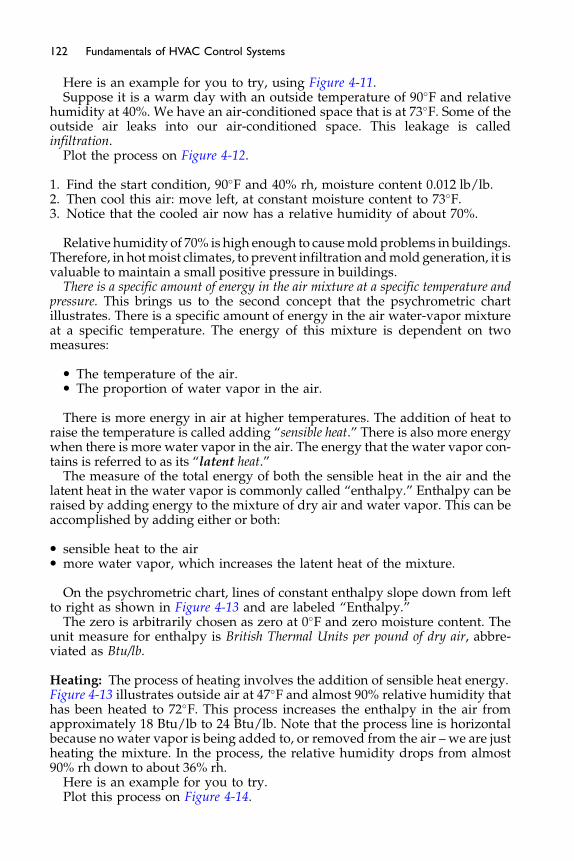
122 Fundamentals of HVAC Control Systems
Here is an example for you to try, using Figure 4-11.Suppose it is a warm day with an outside temperature of 90�F and relative
humidity at 40%. We have an air-conditioned space that is at 73�F. Some of theoutside air leaks into our air-conditioned space. This leakage is calledinfiltration.
Plot the process on Figure 4-12.
1. Find the start condition, 90�F and 40% rh, moisture content 0.012 lb/lb.2. Then cool this air: move left, at constant moisture content to 73�F.3. Notice that the cooled air now has a relative humidity of about 70%.
Relative humidity of 70% is high enough to causemold problems in buildings.Therefore, in hotmoist climates, to prevent infiltration andmold generation, it isvaluable to maintain a small positive pressure in buildings.
There is a specific amount of energy in the air mixture at a specific temperature andpressure. This brings us to the second concept that the psychrometric chartillustrates. There is a specific amount of energy in the air water-vapor mixtureat a specific temperature. The energy of this mixture is dependent on twomeasures:
� The temperature of the air.� The proportion of water vapor in the air.
There is more energy in air at higher temperatures. The addition of heat toraise the temperature is called adding “sensible heat.” There is also more energywhen there is more water vapor in the air. The energy that the water vapor con-tains is referred to as its “latent heat.”
The measure of the total energy of both the sensible heat in the air and thelatent heat in the water vapor is commonly called “enthalpy.” Enthalpy can beraised by adding energy to the mixture of dry air and water vapor. This can beaccomplished by adding either or both:
� sensible heat to the air� more water vapor, which increases the latent heat of the mixture.
On the psychrometric chart, lines of constant enthalpy slope down from leftto right as shown in Figure 4-13 and are labeled “Enthalpy.”
The zero is arbitrarily chosen as zero at 0�F and zero moisture content. Theunit measure for enthalpy is British Thermal Units per pound of dry air, abbre-viated as Btu/lb.
Heating: The process of heating involves the addition of sensible heat energy.Figure 4-13 illustrates outside air at 47�F and almost 90% relative humidity thathas been heated to 72�F. This process increases the enthalpy in the air fromapproximately 18 Btu/lb to 24 Btu/lb. Note that the process line is horizontalbecause no water vapor is being added to, or removed from the air – we are justheating the mixture. In the process, the relative humidity drops from almost90% rh down to about 36% rh.
Here is an example for you to try.Plot this process on Figure 4-14.
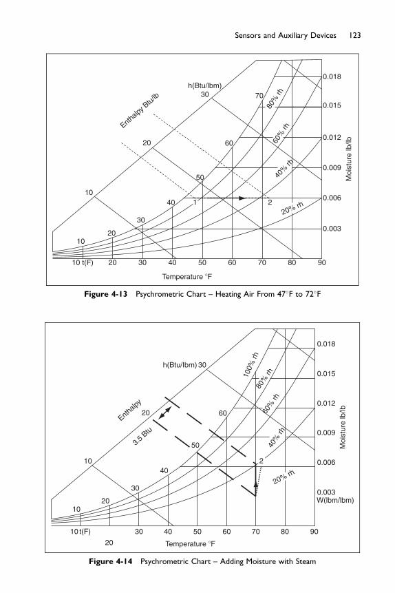
10 t(F)
10
10
20
20
20
Enthalp
y Btu/
lb
30
30
h(Btu/lbm)30
40
40
50
50
Temperature �F
Moi
stur
e Ib
/Ib
60
60
70
70
80
21
90
0.003
0.006
0.009
0.012
0.015
0.018
20% rh
40%
rh
60%
rh
80%
rh
Figure 4-13 Psychrometric Chart – Heating Air From 47�F to 72�F
10
10 t(F)
20
30 40 50
Temperature �F
60 70 80 90
h(Btu/Ibm) 30
80%
rh60
% rh
40%
rh
20
10
30
40
20Enth
alpy
3.5 B
tu
50
60
0.018
0.015100%
rh
0.012
0.009
0.006
Moi
stur
e lb
/lb
0.003W(lbm/lbm)
2
20% rh
Figure 4-14 Psychrometric Chart – Adding Moisture with Steam
123Sensors and Auxiliary Devices
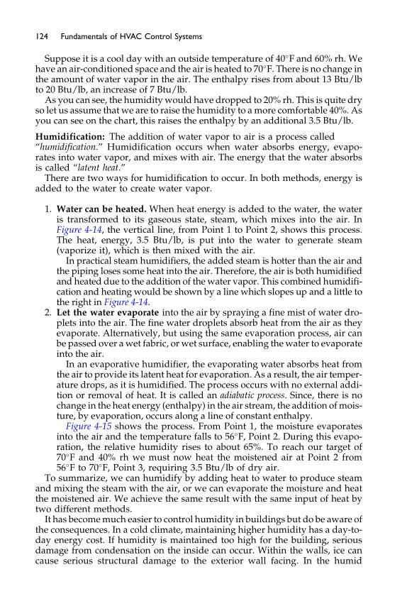
124 Fundamentals of HVAC Control Systems
Suppose it is a cool day with an outside temperature of 40�F and 60% rh. Wehave an air-conditioned space and the air is heated to 70�F. There is no change inthe amount of water vapor in the air. The enthalpy rises from about 13 Btu/lbto 20 Btu/lb, an increase of 7 Btu/lb.
As you can see, the humidity would have dropped to 20% rh. This is quite dryso let us assume that we are to raise the humidity to amore comfortable 40%. Asyou can see on the chart, this raises the enthalpy by an additional 3.5 Btu/lb.
Humidification: The addition of water vapor to air is a process called“humidification.” Humidification occurs when water absorbs energy, evapo-rates into water vapor, and mixes with air. The energy that the water absorbsis called “latent heat.”
There are two ways for humidification to occur. In both methods, energy isadded to the water to create water vapor.
1. Water can be heated. When heat energy is added to the water, the wateris transformed to its gaseous state, steam, which mixes into the air. InFigure 4-14, the vertical line, from Point 1 to Point 2, shows this process.The heat, energy, 3.5 Btu/lb, is put into the water to generate steam(vaporize it), which is then mixed with the air.
In practical steam humidifiers, the added steam is hotter than the air andthe piping loses some heat into the air. Therefore, the air is both humidifiedand heated due to the addition of the water vapor. This combined humidifi-cation and heating would be shown by a line which slopes up and a little tothe right in Figure 4-14.
2. Let the water evaporate into the air by spraying a fine mist of water dro-plets into the air. The fine water droplets absorb heat from the air as theyevaporate. Alternatively, but using the same evaporation process, air canbe passed over awet fabric, or wet surface, enabling thewater to evaporateinto the air.
In an evaporative humidifier, the evaporating water absorbs heat fromthe air to provide its latent heat for evaporation. As a result, the air temper-ature drops, as it is humidified. The process occurs with no external addi-tion or removal of heat. It is called an adiabatic process. Since, there is nochange in the heat energy (enthalpy) in the air stream, the addition ofmois-ture, by evaporation, occurs along a line of constant enthalpy.
Figure 4-15 shows the process. From Point 1, the moisture evaporatesinto the air and the temperature falls to 56�F, Point 2. During this evapo-ration, the relative humidity rises to about 65%. To reach our target of70�F and 40% rh we must now heat the moistened air at Point 2 from56�F to 70�F, Point 3, requiring 3.5 Btu/lb of dry air.
To summarize, we can humidify by adding heat to water to produce steamand mixing the steam with the air, or we can evaporate the moisture and heatthe moistened air. We achieve the same result with the same input of heat bytwo different methods.
It has becomemuch easier to control humidity in buildings but do be aware ofthe consequences. In a cold climate, maintaining higher humidity has a day-to-day energy cost. If humidity is maintained too high for the building, seriousdamage from condensation on the inside can occur. Within the walls, ice cancause serious structural damage to the exterior wall facing. In the humid
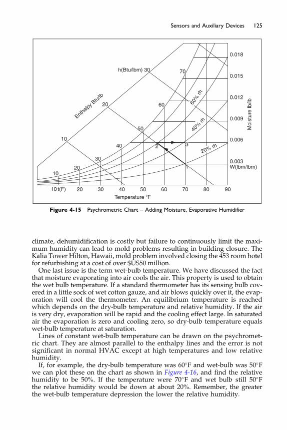
40
50
20
h(Btu/lbm) 30
10
Enthalpy B
tu/lb
60
40%
rh
70
0.018
0.015
0.012
0.009
Moi
stur
e lb
/lb
0.006
0.00330
20
20 30 40 50
Temperature �F
60 70
1
32
80 90
W(lbm/lbm)10
10 t(F)
20% rh
60%
rh
Figure 4-15 Psychrometric Chart – Adding Moisture, Evaporative Humidifier
125Sensors and Auxiliary Devices
climate, dehumidification is costly but failure to continuously limit the maxi-mum humidity can lead to mold problems resulting in building closure. TheKalia Tower Hilton, Hawaii, mold problem involved closing the 453 room hotelfor refurbishing at a cost of over $US50 million.One last issue is the term wet-bulb temperature. We have discussed the fact
that moisture evaporating into air cools the air. This property is used to obtainthe wet bulb temperature. If a standard thermometer has its sensing bulb cov-ered in a little sock of wet cotton gauze, and air blows quickly over it, the evap-oration will cool the thermometer. An equilibrium temperature is reachedwhich depends on the dry-bulb temperature and relative humidity. If the airis very dry, evaporation will be rapid and the cooling effect large. In saturatedair the evaporation is zero and cooling zero, so dry-bulb temperature equalswet-bulb temperature at saturation.Lines of constant wet-bulb temperature can be drawn on the psychromet-
ric chart. They are almost parallel to the enthalpy lines and the error is notsignificant in normal HVAC except at high temperatures and low relativehumidity.If, for example, the dry-bulb temperature was 60�F and wet-bulb was 50�F
we can plot these on the chart as shown in Figure 4-16, and find the relativehumidity to be 50%. If the temperature were 70�F and wet bulb still 50�Fthe relative humidity would be down at about 20%. Remember, the greaterthe wet-bulb temperature depression the lower the relative humidity.
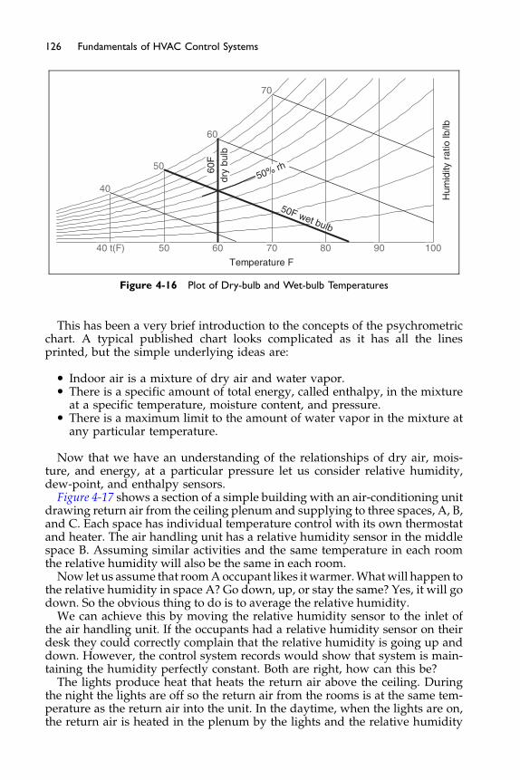
70
50F wet bulb
40
40 t(F)
50
50
60
60
70
80 90 100
50% rh60F
dry
bulb
Temperature F
Hum
idity
rat
io lb
/lb
Figure 4-16 Plot of Dry-bulb and Wet-bulb Temperatures
126 Fundamentals of HVAC Control Systems
This has been a very brief introduction to the concepts of the psychrometricchart. A typical published chart looks complicated as it has all the linesprinted, but the simple underlying ideas are:
� Indoor air is a mixture of dry air and water vapor.� There is a specific amount of total energy, called enthalpy, in the mixture
at a specific temperature, moisture content, and pressure.� There is a maximum limit to the amount of water vapor in the mixture at
any particular temperature.
Now that we have an understanding of the relationships of dry air, mois-ture, and energy, at a particular pressure let us consider relative humidity,dew-point, and enthalpy sensors.
Figure 4-17 shows a section of a simple building with an air-conditioning unitdrawing return air from the ceiling plenum and supplying to three spaces, A, B,and C. Each space has individual temperature control with its own thermostatand heater. The air handling unit has a relative humidity sensor in the middlespace B. Assuming similar activities and the same temperature in each roomthe relative humidity will also be the same in each room.
Now let us assume that roomAoccupant likes it warmer.Whatwill happen tothe relative humidity in space A? Go down, up, or stay the same? Yes, it will godown. So the obvious thing to do is to average the relative humidity.
We can achieve this by moving the relative humidity sensor to the inlet ofthe air handling unit. If the occupants had a relative humidity sensor on theirdesk they could correctly complain that the relative humidity is going up anddown. However, the control system records would show that system is main-taining the humidity perfectly constant. Both are right, how can this be?
The lights produce heat that heats the return air above the ceiling. Duringthe night the lights are off so the return air from the rooms is at the same tem-perature as the return air into the unit. In the daytime, when the lights are on,the return air is heated in the plenum by the lights and the relative humidity
T A T Trh
B C
Air-handlingunit
Return fromceiling plenum
Return air from spaceto ceiling plenum
Figure 4-17 Building Arrangement
127Sensors and Auxiliary Devices
drops. The air handling unit compensates for this by raising the moisture con-tent. This raises the humidity level in the spaces while keeping the relativehumidity constant at the air-handler intake.Now let us imagine that the roof of this building is not perfectly insulated.
When the sun shines on the roof, the heat from the sun will also heat the ple-num. This will also cause the relative humidity in the return air to go downand the air-handler will respond by raising moisture content in the system.In this type of situation it is a bad idea to use return air relative humidity to
control multiple spaces. It is better to either, use one space as the master spaceand maintain its humidity, or to use a dew-point sensor. The dew-point sen-sor can be mounted anywhere in the system as it is not influenced by thedry-bulb temperature. With the dew-point sensor in the return air it sensorwill average the moisture content in all the spaces.Since the relative humidity varies with temperature it is better to specify the
control range for a space in terms of dry-bulb temperature and dew-point (orhumidity ratio) rather than relative humidity.Use of Enthalpy Sensors: Enthalpy sensors can be effective at reducing
cooling costs, particularly in humid climates. Consider a system with an aireconomizer. The question to be answered is: “When should the system stopusing 100% outside air and revert to minimum outside air?” Consider aplant where the return air is at 75�F and 50% relative humidity. This is shownon Figure 4-18. The enthalpy for this return air is also shown in bold. If thesystem uses temperature to make the decision a temperature of 65�F wouldensure that the switch was made before the outside air enthalpy rises abovethe return enthalpy, except for the very occasional possibility that the humid-ity is over 90%. This temperature setting avoids ever bringing in air with ahigher enthalpy than the return air. The conditions for using return air areshown by the hatched area, all temperatures below 65�F and any moisturecontent.Switching at 65�F ensured that excessively high enthalpy outside air is vir-
tually never used but it also switches the plant well before it needs to in manysituations. If, instead the switch is made based on enthalpy one has two
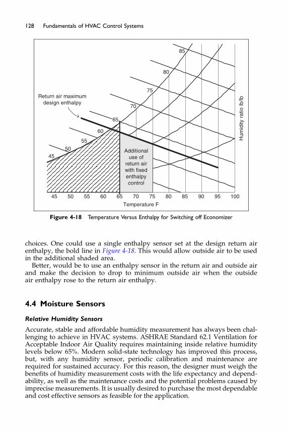
4550
55
60
65
70
75
80
85
45 50 55 60 65 70 75 80 85 90 95 100
Additionaluse of
return airwith fixedenthalpycontrol
Temperature F
Hum
idity
rat
io lb
/lb
Return air maximumdesign enthalpy
Figure 4-18 Temperature Versus Enthalpy for Switching off Economizer
128 Fundamentals of HVAC Control Systems
choices. One could use a single enthalpy sensor set at the design return airenthalpy, the bold line in Figure 4-18. This would allow outside air to be usedin the additional shaded area.
Better, would be to use an enthalpy sensor in the return air and outside airand make the decision to drop to minimum outside air when the outsideair enthalpy rose to the return air enthalpy.
4.4 Moisture Sensors
Relative Humidity Sensors
Accurate, stable and affordable humidity measurement has always been chal-lenging to achieve in HVAC systems. ASHRAE Standard 62.1 Ventilation forAcceptable Indoor Air Quality requires maintaining inside relative humiditylevels below 65%. Modern solid-state technology has improved this process,but, with any humidity sensor, periodic calibration and maintenance arerequired for sustained accuracy. For this reason, the designer must weigh thebenefits of humidity measurement costs with the life expectancy and depend-ability, as well as the maintenance costs and the potential problems caused byimprecise measurements. It is usually desired to purchase the most dependableand cost effective sensors as feasible for the application.

129Sensors and Auxiliary Devices
Humidity may be sensed as relative humidity, dew-point temperature orwet-bulb temperature, with relative humidity being by far the most common.The three parameters are all interrelated and the measurement of any one,along with coincident dry-bulb temperature (and barometric pressure if itvaries significantly), can be used to determine any of the others using knownpsychrometric relationships and be properly used in control applications.Relative Humidity (rh): Historically, the first humidity sensors used hygro-
scopicmaterials (materials that can absorbwater vapor from the air) that changedimension in response to changes in humidity. These include animal hair,wood, and various fabrics, including some synthetic fabrics such as NylonW
and DacronW. These mechanical sensors are still commonly used in portablesensors, such as you might have on your desk, inexpensive electric controls(humidistats), and inexpensive enthalpy economizer controllers. Their accuracyis generally no better than �5% relative humidity, when new, due to variationsin material quality and to hysteresis effects.Resistance-type humidity sensors use hygroscopic materials whose electrical
resistance varies in a repeatable fashionwhen exposed to air of varying humidity.One type uses a sulfonated polystyrene resin placed on an insoluble surface. Anelectrically conductive layer is then bonded to the resin. The electrical resistanceof the assembly varies non-linearly but fairly repeatably with humidity. A linearsignal is created using techniques similar to those used for thermistors describedabove. Like many humidity sensors, the accuracy of the resistance-type sensorcan be severely affected if the surface is contaminated with substances (such asoil) that affect the water vapor absorption or desorption characteristics of theresin.Capacitance-type humidity sensors are available in various forms, all based
on the variation in electrical capacitance of a hygroscopic material. One typeconsists of an aluminum strip deposited with a layer of porous aluminum oxideunderneath a very thin layer of gold. The aluminum and gold form the plates ofthe capacitor, with the aluminum oxide as the dielectric. The capacitance variesas a function of the water vapor absorbed in the aluminum oxide layer. Watervapor is absorbed and desorbed by passing through the very thin layer of gold.The accuracy of this sensor (called a Jason-type hygrometer) is very good up to85% relative humidity but the sensor can become permanently damaged ifexposed to higher humidity air and particularly condensation.A variation of the Jason-type capacitance sensor uses a thin film of polymer
in place of the aluminum oxide, Figure 4-19. The polymer is carefully selectedto provide a capacitance change as a function of humidity but without the85% humidity limitation of aluminum oxide. These sensors are available withaccuracies ranging from �5% rh to as fine as �1% rh, including hysteresis andcalibration uncertainty. Because of their accuracy and reliability, these sensorsare becoming the style most commonly used in analog electronic and digitalcontrol systems. However, they can be expected to drift on the order of 1%to 3% rh per year under normal applications, so as with all humidity sensors,periodic and regular calibration (quarterly) is suggested.Lithium Chloride Dew-point Sensors: Dew-point sensors are the most accu-
rate type of humidity sensor, but they are also the most expensive. One type ofdew-point sensor uses a saturated salt solution (usually lithium chloride) in con-tact with the air whose humidity is to be measured. When steady state is

• Polymer absorbs water
Thin Film Humidity Sensor
• Deposited on conducting grid, and insulating base
• Changes resistance or capacitance
• Accurate +/− 3% RH
• Must watch calibration & contamination
Aluminum Base
Polymer
Gold
Figure 4-19 Thin-film Sensor Example (Hegberg, 2001)
130 Fundamentals of HVAC Control Systems
reached, the temperature of the solution is indicative of the dew-point of the air.This type of sensor is very accurate, very slow to respond, but inaccurate at lowhumidity levels. It is also sensitive to contamination and requires periodicmain-tenance and calibrations, and is relatively expensive. Newer versions use lith-ium chloride solution on a grid with an integral heater. The lithium chloride ishygroscopic and attracts moisture lowering the grid resistance. This loweringresistance increases the heater output which lowers the resistance. The balancebetween wetter lower resistance and heater higher resistance provides the sig-nal for the dew-point. The accuracy of the sensor can be better than �2.5�F.
Chilled-Mirror Dew-point Sensors: Another very accurate dew-point sen-sor is the chilled-mirror type (Figure 4-20).
In these devices, a sample of air flows through a small sensor chamberequippedwith a light source, two photocells, and a chilledmirror. Light reflectsoff the mirror toward one photocell. When condensation forms on the mirror,the light is scattered rather than reflected directly. The system recognizes thisby comparison with the direct reference photocell. The reduction in the lightlevel indicates the presence of condensation on the mirror. At the moment of
TemperatureSensor
T
ThermoelectricCooling Unit
Comparator
Mirror
+
−
PhotocellsLight Source
Figure 4-20 Chilled-mirror Dew-point Sensor

131Sensors and Auxiliary Devices
condensation, an RTD temperature sensor records the surface temperatureof themirror. That surface temperature is the dew-point of the air flowing acrossthe mirror.The surface of the mirror is chilled by an array of semiconductors known as
Peltier junctions, which form a thermoelectric cooler that can be controlled byvarying its electrical current. A control circuit modulates the current passingthrough the semiconductors, keeping the temperature of the mirror constantat the dew-point of the air. Chilled-mirror sensors are not as widely used incommercial buildings as relative humidity sensors, mostly because of theircost and maintenance requirements. But they are highly accurate, and are oftenused to calibrate lower-cost devices. Advantages include:
� They measure the dew-point directly. Controls can be set based on theinstrument’s output signal without the need to calculate the dew-pointbased on temperature and rh.
� They are accurate. Typical dew-point tolerance is �0.4�F.� There is a wide range. Even with a single stage of mirror cooling, the close
tolerance measurement can easily be maintained between temperatures of0 and 100�F with coincident dew-points between �20 and 80�F dry bulb.
Limitations of chilled-mirror sensors include:
� The cost. The lowest-cost versions are about twice as expensive as close-tolerance rh sensors, and the broader-range chilled-mirror devices costabout five times more than the lowest-cost versions.
� Contamination. The mirror surface must be kept clean and free of hygro-scopic dust that creates condensation at a temperature higher than the truedew-point temperature of the air. The air sample must be filtered, and thefilter must be replaced regularly when particulate loading is especiallyheavy.
Nevertheless, where very precise and repeatable humidity measurementsare required, chilled-mirror sensors are a good choice.Figure 4-21 shows different packaging of electrical signal sensors for differ-
ent applications available in the marketplace. Note that the packaging for tem-perature sensors looks (and often is) almost the same.Psychrometers: A psychrometer measures humidity by taking both a wet-
bulb and a dry-bulb temperature reading. With those two values known, theother properties of the air, including its moisture content, can be determined
WallMount
DuctMount
OutdoorMount
Figure 4-21 Examples of Humidity Sensors
132 Fundamentals of HVAC Control Systems
by computation or by reading a psychrometric chart. In commercial buildings,psychrometers are seldom if ever used for control, but they are occasionallyused to check the calibration of humidistats or relative humidity sensors.
Sling psychrometers are a choice for that purpose. These units consist of twothermometers with thin bulbs. One is covered in a cotton sleeve which is wettedwith (ideally distilled) clean water. The two thermometers are mounted in asling which is swung rapidly around-and-around and then quickly read toobtain a steady wet- and dry-bulb temperature. Be careful to use the sling psy-chrometer correctly as it does have some drawbacks. Slow air velocity, inade-quate water coverage of the wick, radiation heating of the wet bulb, andcontamination of the wet wick are compounded by the difficulty of being surethe wet-bulb reading is at its minimum while the thermometer is swinging.These problems mostly come from not slinging long enough to get down towet-bulb steady-state, so the measurement error is always above, rather thanbelow the truewet-bulb reading. In otherwords, poormeasurements from slingpsychrometers will always overestimate the true moisture content. The onlyexception occurs when cold water rather than ambient-temperature water wetsthe wick. In that case, it is possible to underestimate the true humidity level bytaking a reading before stable conditions have been achieved.
Aspirated (fan powered) psychrometers with clean wet wicks using distilledwater are more accurate than sling-type units. An aspirated psychrometer com-bines low cost with the fundamental measurement principle of wet- and dry-bulb readings. For typical humidity ranges of commercial buildings (30 to 60%rh at 68 to 75�F) aspirated psychrometers provide a reliable, low-cost way tocheck readings from low-accuracy sensors.
In an aspirated psychrometer the wet- and dry-bulb thermometers aremounted inside a plastic case, which contains a battery-powered fan. The fandraws air across both dry and wet thermometers at a constant, high velocity toprovide uniform evaporation. The case prevents radiation from influencing thetemperature of the thermometer bulbs. The wickmust be changed regularlywithgloved hands to prevent skin oils and air stream particulate from affecting evapo-ration, and only ambient-temperature distilledwater can be used towet thewick.Further, the wickmust remain completelywetted until the wet-bulb temperaturehas stopped dropping. As long as all those precautions are followed, aspiratedpsychrometers can be useful to cross-check readings from low-accuracy sensors.The advantages of aspirated psychrometers include the following:
� Recalibration is not an issue, as it is with electronic units, since physicalproperties are being directly measured.
� Reasonable accuracy in indoor environments. A tolerance of þ5% of thewet-bulb reading can be achieved in careful operation in middle- andupper-range humidity levels.
� Portable. The instrument can be brought to a room sensor location easily.
The limitations of wet-bulb readings must also remain clear:
� Requires a psychrometric chart. To obtain humidity values, the operatormust carefully plot the point and read values on an accurate psychrometricchart. Plotting and reading introduce twomajor sources of error. Poor resultsfrom aspirated psychrometers usually come from incautious plotting and

133Sensors and Auxiliary Devices
reading of the psychrometric chart after the wet-bulb and dry-bulb readingsare obtained. But, most psychrometers do have charts already engraved ontheir bodies.
� Difficult to use in ducts. The device must draw air only from the duct andnot from the air outside that duct. It is difficult to avoid air mixing whenopening an access door, and difficult to read the results inside a dark duct.
� Difficult to use in low-relative-humidity air. Wet-bulb temperature read-ings below the freezing point of water are difficult to obtain because ittakes a long time to cool the wick low enough to freeze the water, and along time to stabilize the temperature after an ice layer has formed. Theseprecautions are seldom taken outside of a carefully controlled laboratorytest rig. That means psychrometers are seldom useful in low-humidityair streams where sub-freezing wet-bulb temperatures are common.
� Subject to error in reading the thermometers. For accurate results, theoperator cannot neglect to define what fraction of a degree the thermom-eter is sensing. Reading fractions of a degree from small thermometersrequires care, good light, and good eyesight.
� Subject to errors of contamination. In the day-to-day reality of buildingoperations, the wet-bulb wick is not always kept clean of particulate,and is often wetted with mineral-laden water or handled by bare skinwhich adds oils. All of these raise the wet-bulb reading, increasing themeasurement error so the operator overestimates the true humidity.
4.5 Pressure Sensors
Pressure is almost always measured as a differential pressure, either the differ-ence between the pressures of two fluids or the difference in pressure between afluid and a reference pressure.When the reference pressure is atmospheric pres-sure, we refer to the pressure of the fluid as gauge pressure. The name comesfrom the common use of pressure gauges that measure the differencein pressure between a fluid (such as water in a pipe or air in a duct) and theambient air at the gauge location. The absolute pressure of a fluid is the gaugepressure plus atmospheric pressure (roughly 14.7 pounds per square inch atsea level).Water pressure is typically measured in pounds per square inch, designated
as psig (gauge pressure), psia (absolute pressure), or simply psi (differentialpressure). Air pressures are generallymeasured in inches of water gauge, desig-nated as inches H2O, inches wg or sometimes wc (for water column). One inchH2O is equal to 0.036 psi.Mechanical Pressure Gauges: The Bourdon tube (see Figure 4-22) is the sens-
ing element used in most pressure indicating gauges. It is a closed, spiral tube,connected at one end to the pressure being sensed, with atmospheric pressureas a reference. As the sensed pressure increases, the tube tends to straighten,and, through a linkage and gear, drives an indicating pointer. By adding aswitch to the linkage (not shown), the device can become a sensor with switch-ing capability.A spiral tube is similar in principal to the Bourdon tube, but it is formed into a
spiral spring shape that elongates or shortens as the sensed pressure changes.
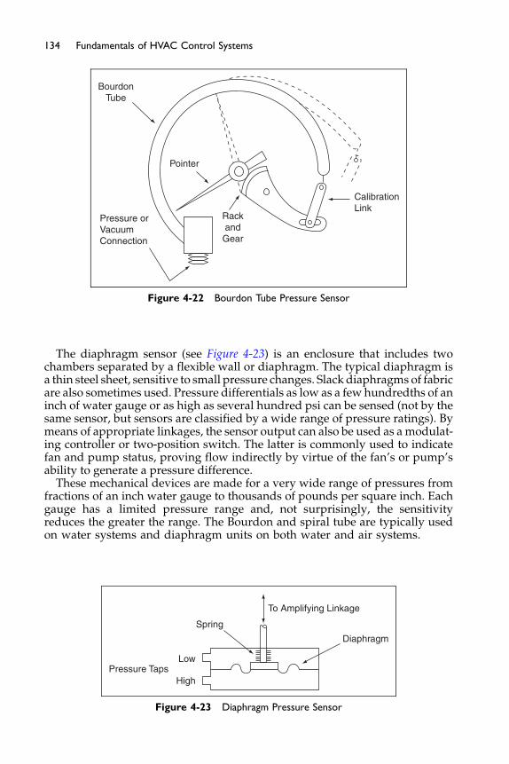
BourdonTube
Pressure orVacuumConnection
Pointer
RackandGear
CalibrationLink
Figure 4-22 Bourdon Tube Pressure Sensor
134 Fundamentals of HVAC Control Systems
The diaphragm sensor (see Figure 4-23) is an enclosure that includes twochambers separated by a flexible wall or diaphragm. The typical diaphragm isa thin steel sheet, sensitive to small pressure changes. Slack diaphragms of fabricare also sometimes used. Pressure differentials as low as a few hundredths of aninch of water gauge or as high as several hundred psi can be sensed (not by thesame sensor, but sensors are classified by a wide range of pressure ratings). Bymeans of appropriate linkages, the sensor output can also be used as a modulat-ing controller or two-position switch. The latter is commonly used to indicatefan and pump status, proving flow indirectly by virtue of the fan’s or pump’sability to generate a pressure difference.
These mechanical devices are made for a very wide range of pressures fromfractions of an inch water gauge to thousands of pounds per square inch. Eachgauge has a limited pressure range and, not surprisingly, the sensitivityreduces the greater the range. The Bourdon and spiral tube are typically usedon water systems and diaphragm units on both water and air systems.
To Amplifying Linkage
Diaphragm
Spring
Low
HighPressure Taps
Figure 4-23 Diaphragm Pressure Sensor
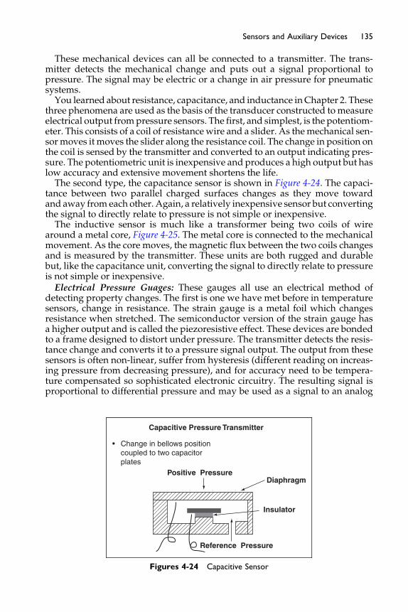
135Sensors and Auxiliary Devices
These mechanical devices can all be connected to a transmitter. The trans-mitter detects the mechanical change and puts out a signal proportional topressure. The signal may be electric or a change in air pressure for pneumaticsystems.You learned about resistance, capacitance, and inductance inChapter 2. These
three phenomena are used as the basis of the transducer constructed tomeasureelectrical output frompressure sensors. The first, and simplest, is the potentiom-eter. This consists of a coil of resistancewire and a slider. As themechanical sen-sormoves it moves the slider along the resistance coil. The change in position onthe coil is sensed by the transmitter and converted to an output indicating pres-sure. The potentiometric unit is inexpensive and produces a high output but haslow accuracy and extensive movement shortens the life.The second type, the capacitance sensor is shown in Figure 4-24. The capaci-
tance between two parallel charged surfaces changes as they move towardand away from each other. Again, a relatively inexpensive sensor but convertingthe signal to directly relate to pressure is not simple or inexpensive.The inductive sensor is much like a transformer being two coils of wire
around a metal core, Figure 4-25. The metal core is connected to the mechanicalmovement. As the core moves, the magnetic flux between the two coils changesand is measured by the transmitter. These units are both rugged and durablebut, like the capacitance unit, converting the signal to directly relate to pressureis not simple or inexpensive.Electrical Pressure Guages: These gauges all use an electrical method of
detecting property changes. The first is one we have met before in temperaturesensors, change in resistance. The strain gauge is a metal foil which changesresistance when stretched. The semiconductor version of the strain gauge hasa higher output and is called the piezoresistive effect. These devices are bondedto a frame designed to distort under pressure. The transmitter detects the resis-tance change and converts it to a pressure signal output. The output from thesesensors is often non-linear, suffer from hysteresis (different reading on increas-ing pressure from decreasing pressure), and for accuracy need to be tempera-ture compensated so sophisticated electronic circuitry. The resulting signal isproportional to differential pressure and may be used as a signal to an analog
Capacitive Pressure Transmitter
Positive Pressure
Reference Pressure
Diaphragm
Insulator
• Change in bellows position coupled to two capacitor plates
Figures 4-24 Capacitive Sensor
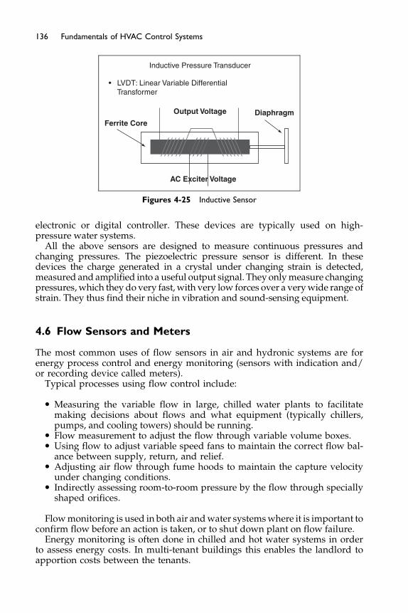
Inductive Pressure Transducer
Ferrite Core
Output Voltage Diaphragm
AC Exciter Voltage
• LVDT: Linear Variable Differential Transformer
Figures 4-25 Inductive Sensor
136 Fundamentals of HVAC Control Systems
electronic or digital controller. These devices are typically used on high-pressure water systems.
All the above sensors are designed to measure continuous pressures andchanging pressures. The piezoelectric pressure sensor is different. In thesedevices the charge generated in a crystal under changing strain is detected,measured and amplified into a useful output signal. They onlymeasure changingpressures,which they do very fast, with very low forces over a verywide range ofstrain. They thus find their niche in vibration and sound-sensing equipment.
4.6 Flow Sensors and Meters
The most common uses of flow sensors in air and hydronic systems are forenergy process control and energy monitoring (sensors with indication and/or recording device called meters).
Typical processes using flow control include:
� Measuring the variable flow in large, chilled water plants to facilitatemaking decisions about flows and what equipment (typically chillers,pumps, and cooling towers) should be running.
� Flow measurement to adjust the flow through variable volume boxes.� Using flow to adjust variable speed fans to maintain the correct flow bal-
ance between supply, return, and relief.� Adjusting air flow through fume hoods to maintain the capture velocity
under changing conditions.� Indirectly assessing room-to-room pressure by the flow through specially
shaped orifices.
Flowmonitoring is used in both air andwater systemswhere it is important toconfirm flow before an action is taken, or to shut down plant on flow failure.
Energy monitoring is often done in chilled and hot water systems in orderto assess energy costs. In multi-tenant buildings this enables the landlord toapportion costs between the tenants.
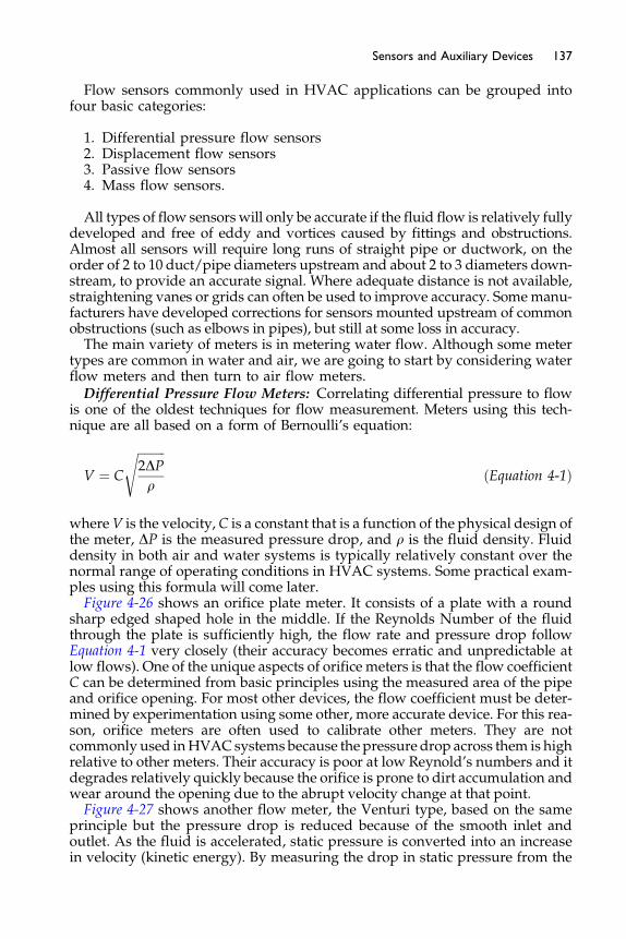
137Sensors and Auxiliary Devices
Flow sensors commonly used in HVAC applications can be grouped intofour basic categories:
1. Differential pressure flow sensors2. Displacement flow sensors3. Passive flow sensors4. Mass flow sensors.
All types of flow sensorswill only be accurate if the fluid flow is relatively fullydeveloped and free of eddy and vortices caused by fittings and obstructions.Almost all sensors will require long runs of straight pipe or ductwork, on theorder of 2 to 10 duct/pipe diameters upstream and about 2 to 3 diameters down-stream, to provide an accurate signal. Where adequate distance is not available,straightening vanes or grids can often be used to improve accuracy. Somemanu-facturers have developed corrections for sensors mounted upstream of commonobstructions (such as elbows in pipes), but still at some loss in accuracy.The main variety of meters is in metering water flow. Although some meter
types are common in water and air, we are going to start by considering waterflow meters and then turn to air flow meters.Differential Pressure Flow Meters: Correlating differential pressure to flow
is one of the oldest techniques for flow measurement. Meters using this tech-nique are all based on a form of Bernoulli’s equation:
V ¼ C
ffiffiffiffiffiffiffiffiffi2DPr
s
ðEquation 4-1Þ
whereV is the velocity, C is a constant that is a function of the physical design ofthe meter, DP is the measured pressure drop, and r is the fluid density. Fluiddensity in both air and water systems is typically relatively constant over thenormal range of operating conditions in HVAC systems. Some practical exam-ples using this formula will come later.Figure 4-26 shows an orifice plate meter. It consists of a plate with a round
sharp edged shaped hole in the middle. If the Reynolds Number of the fluidthrough the plate is sufficiently high, the flow rate and pressure drop followEquation 4-1 very closely (their accuracy becomes erratic and unpredictable atlow flows). One of the unique aspects of orifice meters is that the flow coefficientC can be determined from basic principles using the measured area of the pipeand orifice opening. For most other devices, the flow coefficient must be deter-mined by experimentation using some other, more accurate device. For this rea-son, orifice meters are often used to calibrate other meters. They are notcommonly used inHVACsystems because the pressure drop across them is highrelative to other meters. Their accuracy is poor at low Reynold’s numbers and itdegrades relatively quickly because the orifice is prone to dirt accumulation andwear around the opening due to the abrupt velocity change at that point.Figure 4-27 shows another flow meter, the Venturi type, based on the same
principle but the pressure drop is reduced because of the smooth inlet andoutlet. As the fluid is accelerated, static pressure is converted into an increasein velocity (kinetic energy). By measuring the drop in static pressure from the
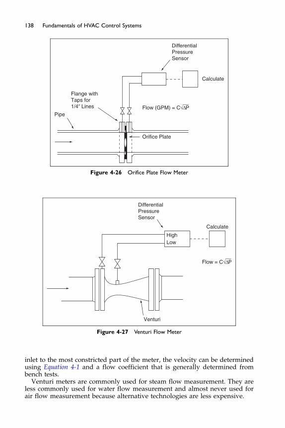
DifferentialPressureSensor
Calculate
Flow (GPM) = C√_Δ P_
Orifice Plate
Flange withTaps for1/4� Lines
Pipe
Figure 4-26 Orifice Plate Flow Meter
DifferentialPressureSensor
Calculate
HighLow
Flow = C√_Δ P_
Venturi
Figure 4-27 Venturi Flow Meter
138 Fundamentals of HVAC Control Systems
inlet to the most constricted part of the meter, the velocity can be determinedusing Equation 4-1 and a flow coefficient that is generally determined frombench tests.
Venturi meters are commonly used for steam flow measurement. They areless commonly used for water flow measurement and almost never used forair flow measurement because alternative technologies are less expensive.
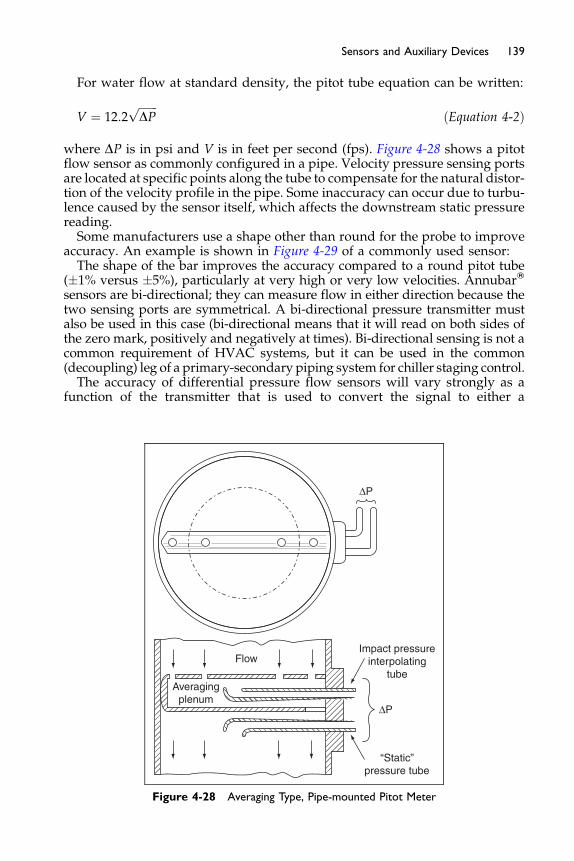
139Sensors and Auxiliary Devices
For water flow at standard density, the pitot tube equation can be written:
V ¼ 12:2ffiffiffiffiffiffiffiDP
pðEquation 4-2Þ
where DP is in psi and V is in feet per second (fps). Figure 4-28 shows a pitotflow sensor as commonly configured in a pipe. Velocity pressure sensing portsare located at specific points along the tube to compensate for the natural distor-tion of the velocity profile in the pipe. Some inaccuracy can occur due to turbu-lence caused by the sensor itself, which affects the downstream static pressurereading.Some manufacturers use a shape other than round for the probe to improve
accuracy. An example is shown in Figure 4-29 of a commonly used sensor:The shape of the bar improves the accuracy compared to a round pitot tube
(�1% versus �5%), particularly at very high or very low velocities. AnnubarW
sensors are bi-directional; they can measure flow in either direction because thetwo sensing ports are symmetrical. A bi-directional pressure transmitter mustalso be used in this case (bi-directional means that it will read on both sides ofthe zero mark, positively and negatively at times). Bi-directional sensing is not acommon requirement of HVAC systems, but it can be used in the common(decoupling) leg of a primary-secondary piping system for chiller staging control.The accuracy of differential pressure flow sensors will vary strongly as a
function of the transmitter that is used to convert the signal to either a
Impact pressureinterpolating
tube
ΔP
ΔP
“Static”pressure tube
Averagingplenum
Flow
Figure 4-28 Averaging Type, Pipe-mounted Pitot Meter

Pipe or Duct
Flow
Flow
Fixedseparation
point
Downstreamaveragingchamber
Diamond-shapedannubar
averaging tube
Standard roundpitot
averaging tube
Variable separation point
Upstreamaveragingchamber
Figure 4-29 AnnubarW Flow Sensor
140 Fundamentals of HVAC Control Systems
pneumatic or electronic signal for use by the control system. As the pressuresignal falls, the accuracy of the flow sensor also falls. The transmitter mustbe selected for the maximum pressure (maximum velocity) it must sense,but this usually makes it oversized for low flows and accuracy falls off quicklyat velocities below about 25% of the maximum.
Displacement Flow Meters: Displacement flow meters work by using thefluid to rotate or displace a device inserted into the fluid stream. A simple exam-ple is the paddle flow switch shown in Figure 4-30 which is commonly used to“prove” fluid flow in a pipe. It is screwed into a tee or weldolet and includes aswitch that is activated when fluid flow deflects the paddle. A similar devicewith a larger and lighter paddle called a sail switch is used in air systems. Bothof these devices are sensitive to physical damage, dirt, and corrosion, andrequire regular maintenance to ensure reliability.
Figure 4-31 shows a turbinemeter thatmeasures the flow by counting the rota-tions of a propeller-shaped rotor placed in the fluid stream.This is a very commonsensor for water flow measurement in HVAC systems. Rotations are commonlycounted using magnetic sensors (requiring a metal rotor), infrared light reflec-tions from the blade being counted, or non-magnetic radio frequency impedancesensors (requiring some electrical conductivity of the fluid; fluids other thandeio-nized water). Some turbine meters are bi-directional. Accuracy can be improvedby using a dual turbine meter that has two turbines mounted in parallel withrotors that rotate in opposite directions. These meters offer improved accuracy
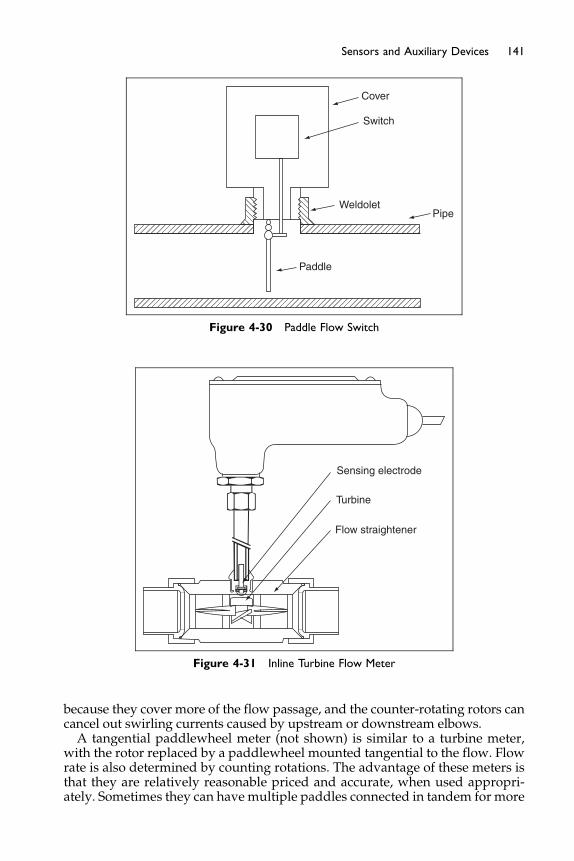
Cover
Switch
WeldoletPipe
Paddle
Figure 4-30 Paddle Flow Switch
Sensing electrode
Turbine
Flow straightener
Figure 4-31 Inline Turbine Flow Meter
141Sensors and Auxiliary Devices
because they cover more of the flow passage, and the counter-rotating rotors cancancel out swirling currents caused by upstream or downstream elbows.A tangential paddlewheel meter (not shown) is similar to a turbine meter,
with the rotor replaced by a paddlewheel mounted tangential to the flow. Flowrate is also determined by counting rotations. The advantage of these meters isthat they are relatively reasonable priced and accurate, when used appropri-ately. Sometimes they can havemultiple paddles connected in tandem for more
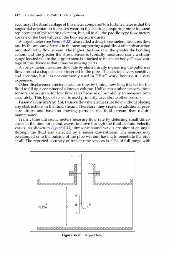
142 Fundamentals of HVAC Control Systems
accuracy. The disadvantage of thismeter compared to a turbinemeter is that thetangential orientation increases wear on the bearings, requiring more frequentreplacement of the rotating element, but, all in all, the paddle-type flow metersare one of the best values in the flow sensor industry.
A target meter (see Figure 4-32), also called a drag-force meter, measures flowrate by the amount of stress in the stem supporting a paddle or other obstructionmounted in the flow stream. The higher the flow rate, the greater the bendingaction, and the greater the stress. Stress is typically measured using a strain-gauge locatedwhere the support stem is attached to themeter body. One advan-tage of this device is that it has no moving parts.
A vortex meter measures flow rate by electronically measuring the pattern offlow around a shaped sensor inserted in the pipe. This device is very sensitiveand accurate, but it is not commonly used in HVAC work, because it is veryexpensive.
Other displacement meters measure flow by timing how long it takes for thefluid to fill up a container of a known volume. Unlike most other sensors, thesesensors are accurate for low flow rates because of our ability to measure timeaccurately. This type of sensor is used primarily to calibrate other sensors.
Passive Flow Meters: [14]Passive flowmetersmeasure flowwithout placingany obstructions in the fluid stream. Therefore, they create no additional pres-sure drops and have no moving parts in the fluid stream that requiremaintenance.
Transit time ultrasonic meters measure flow rate by detecting small differ-ences in the time for sound waves to move through the fluid as fluid velocityvaries. As shown in Figure 4-33, ultrasonic sound waves are shot at an anglethrough the fluid and detected by a sensor downstream. The sensors maybe clamped onto the outside of the pipe without having to penetrate the pipeat all. The reported accuracy of transit-time sensors is �1% of full range with
DFLOW
F
d
Figure 4-32 Target Meter
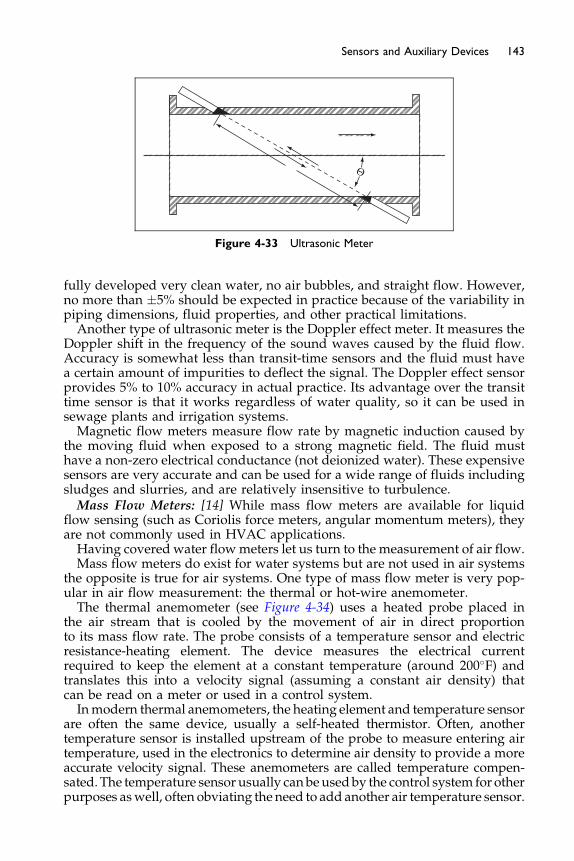
Θ
Figure 4-33 Ultrasonic Meter
143Sensors and Auxiliary Devices
fully developed very clean water, no air bubbles, and straight flow. However,no more than �5% should be expected in practice because of the variability inpiping dimensions, fluid properties, and other practical limitations.Another type of ultrasonic meter is the Doppler effect meter. It measures the
Doppler shift in the frequency of the sound waves caused by the fluid flow.Accuracy is somewhat less than transit-time sensors and the fluid must havea certain amount of impurities to deflect the signal. The Doppler effect sensorprovides 5% to 10% accuracy in actual practice. Its advantage over the transittime sensor is that it works regardless of water quality, so it can be used insewage plants and irrigation systems.Magnetic flow meters measure flow rate by magnetic induction caused by
the moving fluid when exposed to a strong magnetic field. The fluid musthave a non-zero electrical conductance (not deionized water). These expensivesensors are very accurate and can be used for a wide range of fluids includingsludges and slurries, and are relatively insensitive to turbulence.Mass Flow Meters: [14] While mass flow meters are available for liquid
flow sensing (such as Coriolis force meters, angular momentum meters), theyare not commonly used in HVAC applications.Having covered water flowmeters let us turn to the measurement of air flow.Mass flow meters do exist for water systems but are not used in air systems
the opposite is true for air systems. One type of mass flow meter is very pop-ular in air flow measurement: the thermal or hot-wire anemometer.The thermal anemometer (see Figure 4-34) uses a heated probe placed in
the air stream that is cooled by the movement of air in direct proportionto its mass flow rate. The probe consists of a temperature sensor and electricresistance-heating element. The device measures the electrical currentrequired to keep the element at a constant temperature (around 200�F) andtranslates this into a velocity signal (assuming a constant air density) thatcan be read on a meter or used in a control system.Inmodern thermal anemometers, the heating element and temperature sensor
are often the same device, usually a self-heated thermistor. Often, anothertemperature sensor is installed upstream of the probe to measure entering airtemperature, used in the electronics to determine air density to provide a moreaccurate velocity signal. These anemometers are called temperature compen-sated. The temperature sensor usually canbeusedby the control system for otherpurposes aswell, often obviating the need to add another air temperature sensor.
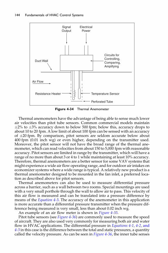
ElectricalPower
SignalOutput
Circuits forControlling,Comparing,Amplifying
Temperature Sensor
Perforated Tube
Resistance Heater
Duct Wall
Air Flow
Figure 4-34 Thermal Anemometer
144 Fundamentals of HVAC Control Systems
Thermal anemometers have the advantage of being able to sense much lowerair velocities than pitot tube sensors. Common commercial models maintain�2% to �3% accuracy down to below 500 fpm; below this, accuracy drops toabout 10 to 20 fpm. A low limit of about 100 fpm can be sensedwith an accuracyof �20 fpm. By comparison, pitot sensors are seldom accurate below about400 fpm (0.01 inch wg) or even higher, depending on the transmitter used.Moreover, the pitot sensor will not have the broad range of the thermal ane-mometer, which can read velocities from about 150 to 5,000 fpmwith reasonableaccuracy. Pitot sensors are limited in range by the transmitter, which will have arange of no more than about 3 or 4 to 1 while maintaining at least 10% accuracy.Therefore, thermal anemometers are a better sensor for some VAV systems thatmight experience awide air flow operating range, and for outdoor air intakes oneconomizer systemswhere awide range is typical. A relatively new product is athermal anemometer designed to be mounted in the fan inlet, a preferred loca-tion as described above for pitot sensors.
Thermal anemometers can also be used to measure differential pressureacross a barrier, such as a wall between two rooms. Special mountings are usedwith a very small porthole through the wall to allow air to pass. This velocity ofthis air flow is measured and can be translated into a pressure difference bymeans of the Equation 4-3. The accuracy of the anemometer in this applicationis more accurate than a differential pressure transmitter when the pressure dif-ference being measured is very small, less than about 0.02 inch wg.
An example of an air flow meter is shown in Figure 4-35.Pitot tube sensors (see Figure 4-36) are commonly used to measure the speed
of aircraft. They are also used very commonly for measuring both air and waterflow in HVAC applications. The differential pressure in Equations 4-1, 4-2, and4-3 in this case is the difference between the total and static pressures, a quantitycalled the velocity pressure. As can be seen in Figure 4-36, the inner tube senses
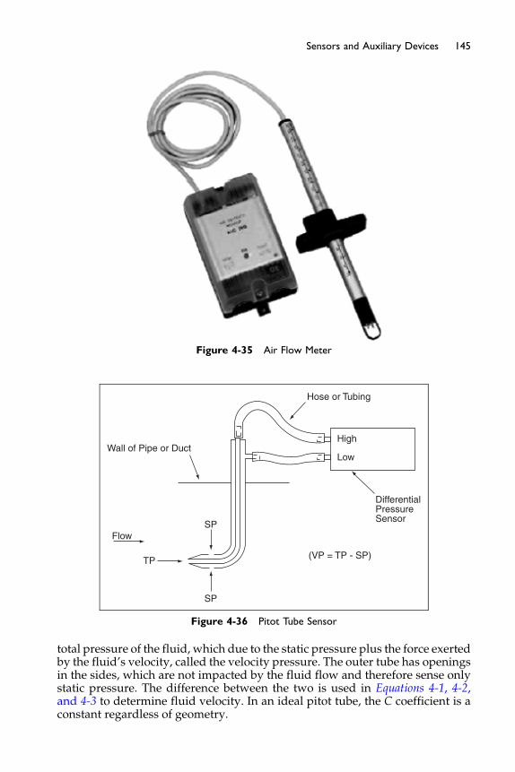
Figure 4-35 Air Flow Meter
Hose or Tubing
High
Low
DifferentialPressureSensor
(VP = TP - SP)
SP
SP
TP
Flow
Wall of Pipe or Duct
Figure 4-36 Pitot Tube Sensor
145Sensors and Auxiliary Devices
total pressure of the fluid, which due to the static pressure plus the force exertedby the fluid’s velocity, called the velocity pressure. The outer tube has openingsin the sides, which are not impacted by the fluid flow and therefore sense onlystatic pressure. The difference between the two is used in Equations 4-1, 4-2,and 4-3 to determine fluid velocity. In an ideal pitot tube, the C coefficient is aconstant regardless of geometry.

146 Fundamentals of HVAC Control Systems
For air flow at standard density, velocity may be calculated from the pitottube velocity differential pressure as:
V ¼ 4005ffiffiffiffiffiffiffiDP
pðEquation 4-3Þ
where DP is measured in inches of water gauge (wg) and V is measured in feetper minute (fpm).
Figure 4-37 shows an air flowmeasuring station (FMS) commonly used in ductapplications.
In large ducts, the FMS is composed of an array of pitot sampling tubes thepressure signals of which are averaged. This signal is fed to a square root extrac-tor, which is a transmitter that converts the differential pressure signal into avelocity signal. (With digital control systems, this calculation can be made insoftware with improved accuracy over the use of a square root extractor.) Thevelocity measured in this way is an approximate average of duct velocity, butit is not a precise average because pressure and velocity are not proportional(the average of the square of velocity is not equal to the average of the velocity).
Where fan air flow rate measurement is required, the preferred location ofthe pitot sensor is in the inlet of the fan. Two arrangements are available.The first, which can be used with almost any fan, has two bars with multiplevelocity pressure and static pressure ports mounted on either side of the fanaxis. The second, much less common arrangement has multiple pinhole pres-sure taps that are built into the fan inlet by the fan manufacturer. Differentialpressure is measured from the outer point of the inlet to the most constrictedpoint, much like a Venturi meter.
Locating the air flow sensor in the fan inlet hasmany advantages compared toa duct mounted pitot array. First, air flow is generally stable in the inlet (exceptwhen inlet vanes are used, in which case this location is not recommended) and
Flow (CFM) = Average Velocity � Area
Air Flow
Duct Wall Manifold
Integrate andTotalize
PressureDifferentialSensor
Static Pressure Tip(Also Averaged)
Total Pressure Tubewith Several Openings(a Series of theseAcross the Duct)
Figure 4-37 Air Flow Measuring Station
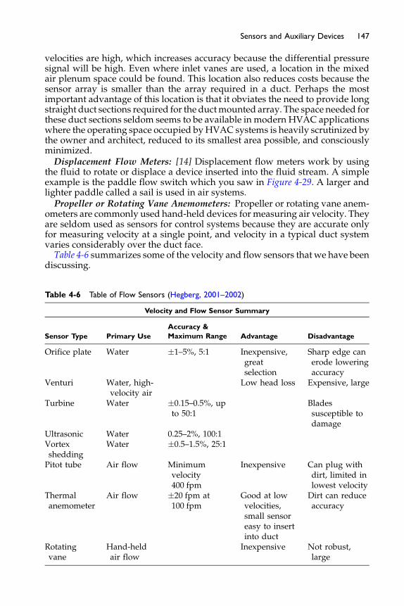
147Sensors and Auxiliary Devices
velocities are high, which increases accuracy because the differential pressuresignal will be high. Even where inlet vanes are used, a location in the mixedair plenum space could be found. This location also reduces costs because thesensor array is smaller than the array required in a duct. Perhaps the mostimportant advantage of this location is that it obviates the need to provide longstraight duct sections required for the ductmounted array. The space needed forthese duct sections seldom seems to be available in modern HVAC applicationswhere the operating space occupied byHVAC systems is heavily scrutinized bythe owner and architect, reduced to its smallest area possible, and consciouslyminimized.Displacement Flow Meters: [14] Displacement flow meters work by using
the fluid to rotate or displace a device inserted into the fluid stream. A simpleexample is the paddle flow switch which you saw in Figure 4-29. A larger andlighter paddle called a sail is used in air systems.Propeller or Rotating Vane Anemometers: Propeller or rotating vane anem-
ometers are commonly used hand-held devices for measuring air velocity. Theyare seldom used as sensors for control systems because they are accurate onlyfor measuring velocity at a single point, and velocity in a typical duct systemvaries considerably over the duct face.Table 4-6 summarizes some of the velocity and flow sensors that we have been
discussing.
Table 4-6 Table of Flow Sensors (Hegberg, 2001–2002)
Velocity and Flow Sensor Summary
Sensor Type Primary Use
Accuracy &
Maximum Range Advantage Disadvantage
Orifice plate Water �1–5%, 5:1 Inexpensive,greatselection
Sharp edge canerode loweringaccuracy
Venturi Water, high-velocity air
Low head loss Expensive, large
Turbine Water �0.15–0.5%, upto 50:1
Bladessusceptible todamage
Ultrasonic Water 0.25–2%, 100:1Vortexshedding
Water �0.5–1.5%, 25:1
Pitot tube Air flow Minimumvelocity400 fpm
Inexpensive Can plug withdirt, limited inlowest velocity
Thermalanemometer
Air flow �20 fpm at100 fpm
Good at lowvelocities,small sensoreasy to insertinto duct
Dirt can reduceaccuracy
Rotatingvane
Hand-heldair flow
Inexpensive Not robust,large
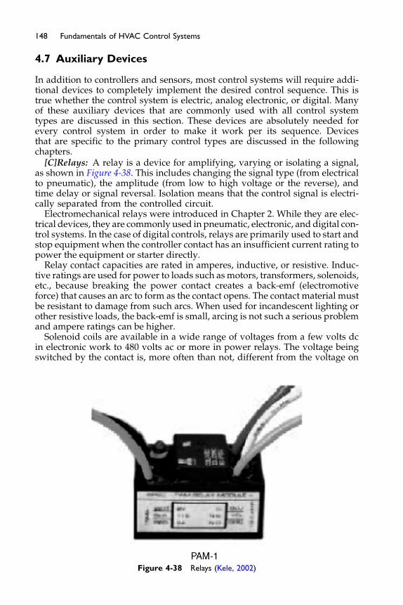
148 Fundamentals of HVAC Control Systems
4.7 Auxiliary Devices
In addition to controllers and sensors, most control systems will require addi-tional devices to completely implement the desired control sequence. This istrue whether the control system is electric, analog electronic, or digital. Manyof these auxiliary devices that are commonly used with all control systemtypes are discussed in this section. These devices are absolutely needed forevery control system in order to make it work per its sequence. Devicesthat are specific to the primary control types are discussed in the followingchapters.
[C]Relays: A relay is a device for amplifying, varying or isolating a signal,as shown in Figure 4-38. This includes changing the signal type (from electricalto pneumatic), the amplitude (from low to high voltage or the reverse), andtime delay or signal reversal. Isolation means that the control signal is electri-cally separated from the controlled circuit.
Electromechanical relays were introduced in Chapter 2. While they are elec-trical devices, they are commonly used in pneumatic, electronic, and digital con-trol systems. In the case of digital controls, relays are primarily used to start andstop equipment when the controller contact has an insufficient current rating topower the equipment or starter directly.
Relay contact capacities are rated in amperes, inductive, or resistive. Induc-tive ratings are used for power to loads such asmotors, transformers, solenoids,etc., because breaking the power contact creates a back-emf (electromotiveforce) that causes an arc to form as the contact opens. The contact material mustbe resistant to damage from such arcs. When used for incandescent lighting orother resistive loads, the back-emf is small, arcing is not such a serious problemand ampere ratings can be higher.
Solenoid coils are available in a wide range of voltages from a few volts dcin electronic work to 480 volts ac or more in power relays. The voltage beingswitched by the contact is, more often than not, different from the voltage on
Figure 4-38 Relays (Kele, 2002)
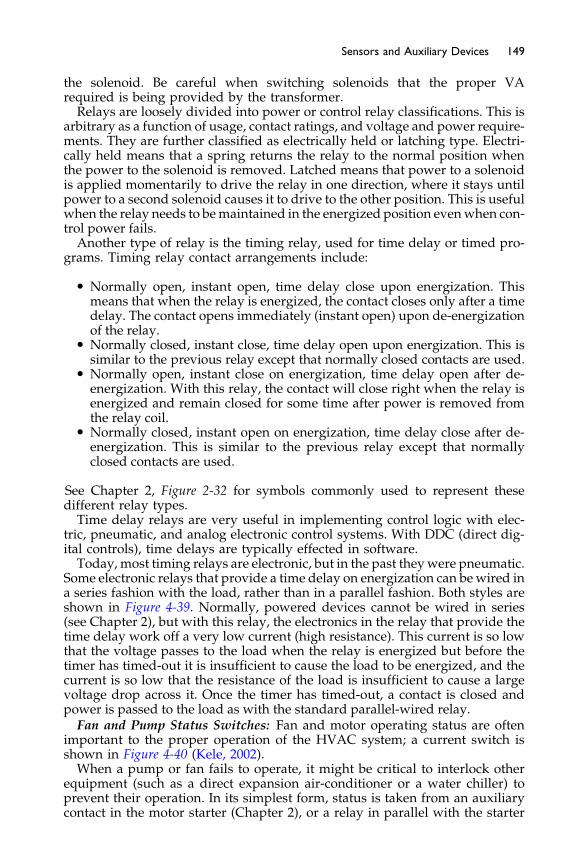
149Sensors and Auxiliary Devices
the solenoid. Be careful when switching solenoids that the proper VArequired is being provided by the transformer.Relays are loosely divided into power or control relay classifications. This is
arbitrary as a function of usage, contact ratings, and voltage and power require-ments. They are further classified as electrically held or latching type. Electri-cally held means that a spring returns the relay to the normal position whenthe power to the solenoid is removed. Latched means that power to a solenoidis applied momentarily to drive the relay in one direction, where it stays untilpower to a second solenoid causes it to drive to the other position. This is usefulwhen the relay needs to bemaintained in the energized position evenwhen con-trol power fails.Another type of relay is the timing relay, used for time delay or timed pro-
grams. Timing relay contact arrangements include:
� Normally open, instant open, time delay close upon energization. Thismeans that when the relay is energized, the contact closes only after a timedelay. The contact opens immediately (instant open) upon de-energizationof the relay.
� Normally closed, instant close, time delay open upon energization. This issimilar to the previous relay except that normally closed contacts are used.
� Normally open, instant close on energization, time delay open after de-energization. With this relay, the contact will close right when the relay isenergized and remain closed for some time after power is removed fromthe relay coil.
� Normally closed, instant open on energization, time delay close after de-energization. This is similar to the previous relay except that normallyclosed contacts are used.
See Chapter 2, Figure 2-32 for symbols commonly used to represent thesedifferent relay types.Time delay relays are very useful in implementing control logic with elec-
tric, pneumatic, and analog electronic control systems. With DDC (direct dig-ital controls), time delays are typically effected in software.Today, most timing relays are electronic, but in the past theywere pneumatic.
Some electronic relays that provide a time delay on energization can bewired ina series fashion with the load, rather than in a parallel fashion. Both styles areshown in Figure 4-39. Normally, powered devices cannot be wired in series(see Chapter 2), but with this relay, the electronics in the relay that provide thetime delay work off a very low current (high resistance). This current is so lowthat the voltage passes to the load when the relay is energized but before thetimer has timed-out it is insufficient to cause the load to be energized, and thecurrent is so low that the resistance of the load is insufficient to cause a largevoltage drop across it. Once the timer has timed-out, a contact is closed andpower is passed to the load as with the standard parallel-wired relay.Fan and Pump Status Switches: Fan and motor operating status are often
important to the proper operation of the HVAC system; a current switch isshown in Figure 4-40 (Kele, 2002).When a pump or fan fails to operate, it might be critical to interlock other
equipment (such as a direct expansion air-conditioner or a water chiller) toprevent their operation. In its simplest form, status is taken from an auxiliarycontact in the motor starter (Chapter 2), or a relay in parallel with the starter
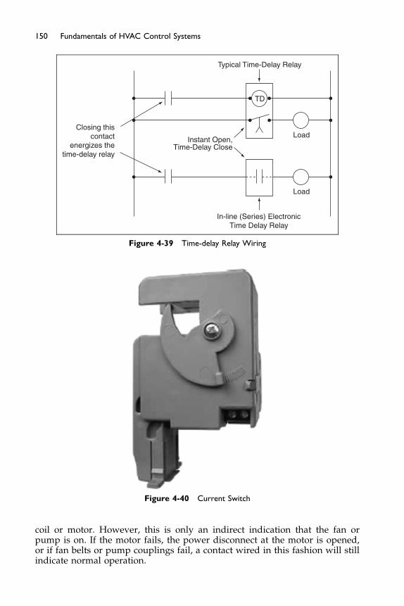
Typical Time-Delay Relay
TD
Load
Load
In-line (Series) ElectronicTime Delay Relay
Closing thiscontact
energizes thetime-delay relay
Instant Open,Time-Delay Close
Figure 4-39 Time-delay Relay Wiring
Figure 4-40 Current Switch
150 Fundamentals of HVAC Control Systems
coil or motor. However, this is only an indirect indication that the fan orpump is on. If the motor fails, the power disconnect at the motor is opened,or if fan belts or pump couplings fail, a contact wired in this fashion will stillindicate normal operation.

151Sensors and Auxiliary Devices
For this reason, it is desirable to sense the real operating condition of the fan orpump or the motor driving it. In common practice, this is done by means of apaddle or sail switch in the duct or piping, a differential pressure switch acrossthe fan or pump, or a current switchmounted on the power wiring to themotor.The flow and differential pressure switches (discussed in the sensor sections
and an example shown in Figure 4-41 (Kele, 2002) tend to be problematic inpractice, particularly on fan systems due to sensitive set points and failuresof paddles over time, however they are still widely used to sense filter status,and air flow proving for electric heaters. The current switch is rapidly takingtheir place because it is more reliable and less expensive to install. This deviceincludes an induction coil as part of a bridge circuit, which allows it to sense thecurrent flow in one phase of the power wiring. The sensed value is compared toa set point that corresponds to a normal operating current. The set point can behigh enough to distinguish between an unloadedmotor (as might occur if a beltor linkage was broken) and a blocked tight condition (as might occur if adamper or valve had shut off, completely blocking flow). Therefore, the currentrelay is almost as dependable at indicating true fan or pump status as a flowswitch, more dependable than a differential pressure switch (which is not ableto distinguish between the blocked-tight condition and normal operation), andit is significantly more reliable and less expensive to install.Timeclocks: Timeclocks are used for starting and stopping equipment on a
regular cycle.Mechanical timeclocks are available for 24-hour or seven-day pro-grams. On/off initiation is generally accomplished using pins attached to awheel that rotateswith time. The pin’s location on thewheel determines the startand stop times. When the pins rotate past a switch, they push it either open orclosed. Mechanical timeclocks generally need to be adjusted for time changes(for example, standard to daylight savings) and must be reset after power fail-ure. Battery backup is sometimes provided to avoid the latter problem.
Figure 4-41 Pressure Switch
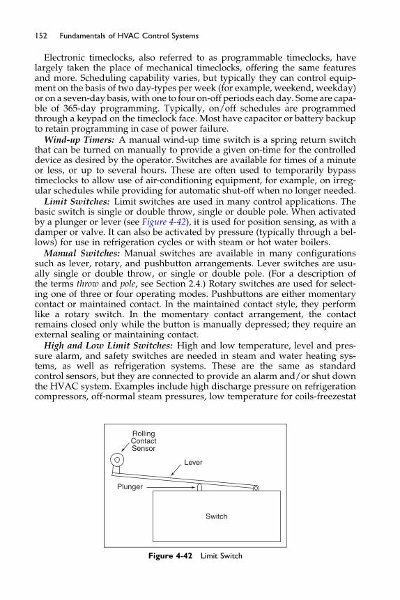
152 Fundamentals of HVAC Control Systems
Electronic timeclocks, also referred to as programmable timeclocks, havelargely taken the place of mechanical timeclocks, offering the same featuresand more. Scheduling capability varies, but typically they can control equip-ment on the basis of two day-types per week (for example, weekend, weekday)or on a seven-day basis, with one to four on-off periods each day. Some are capa-ble of 365-day programming. Typically, on/off schedules are programmedthrough a keypad on the timeclock face. Most have capacitor or battery backupto retain programming in case of power failure.
Wind-up Timers: A manual wind-up time switch is a spring return switchthat can be turned on manually to provide a given on-time for the controlleddevice as desired by the operator. Switches are available for times of a minuteor less, or up to several hours. These are often used to temporarily bypasstimeclocks to allow use of air-conditioning equipment, for example, on irreg-ular schedules while providing for automatic shut-off when no longer needed.
Limit Switches: Limit switches are used in many control applications. Thebasic switch is single or double throw, single or double pole. When activatedby a plunger or lever (see Figure 4-42), it is used for position sensing, as with adamper or valve. It can also be activated by pressure (typically through a bel-lows) for use in refrigeration cycles or with steam or hot water boilers.
Manual Switches: Manual switches are available in many configurationssuch as lever, rotary, and pushbutton arrangements. Lever switches are usu-ally single or double throw, or single or double pole. (For a description ofthe terms throw and pole, see Section 2.4.) Rotary switches are used for select-ing one of three or four operating modes. Pushbuttons are either momentarycontact or maintained contact. In the maintained contact style, they performlike a rotary switch. In the momentary contact arrangement, the contactremains closed only while the button is manually depressed; they require anexternal sealing or maintaining contact.
High and Low Limit Switches: High and low temperature, level and pres-sure alarm, and safety switches are needed in steam and water heating sys-tems, as well as refrigeration systems. These are the same as standardcontrol sensors, but they are connected to provide an alarm and/or shut downthe HVAC system. Examples include high discharge pressure on refrigerationcompressors, off-normal steam pressures, low temperature for coils-freezestat
Switch
Plunger
Lever
RollingContactSensor
Figure 4-42 Limit Switch
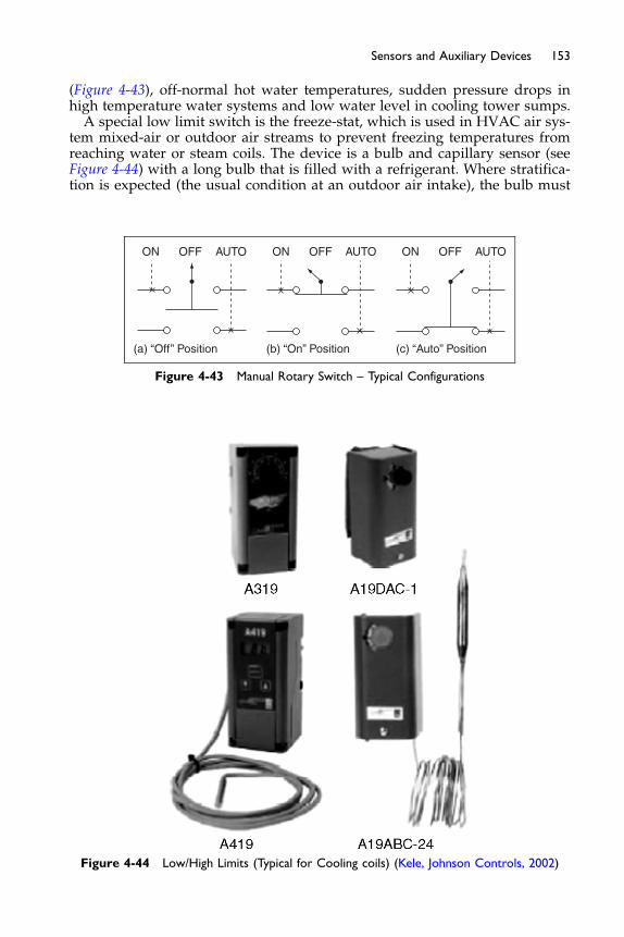
153Sensors and Auxiliary Devices
(Figure 4-43), off-normal hot water temperatures, sudden pressure drops inhigh temperature water systems and low water level in cooling tower sumps.A special low limit switch is the freeze-stat, which is used in HVAC air sys-
tem mixed-air or outdoor air streams to prevent freezing temperatures fromreaching water or steam coils. The device is a bulb and capillary sensor (seeFigure 4-44) with a long bulb that is filled with a refrigerant. Where stratifica-tion is expected (the usual condition at an outdoor air intake), the bulb must
ON OFF AUTO AUTO AUTOON ONOFF OFF
(a) “Off” Position (b) “On” Position (c) “Auto” Position
Figure 4-43 Manual Rotary Switch – Typical Configurations
Figure 4-44 Low/High Limits (Typical for Cooling coils) (Kele, Johnson Controls, 2002)
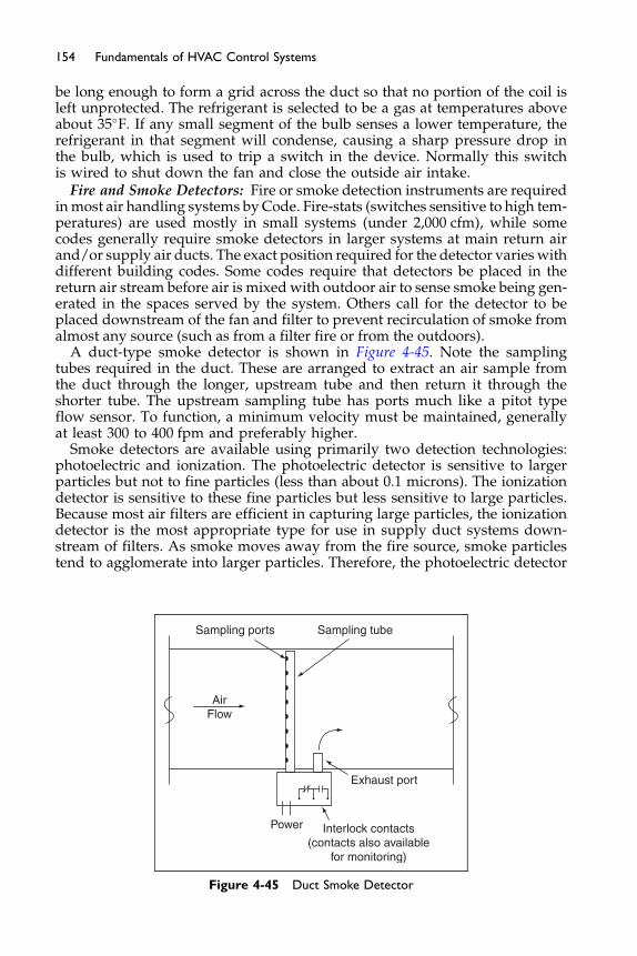
154 Fundamentals of HVAC Control Systems
be long enough to form a grid across the duct so that no portion of the coil isleft unprotected. The refrigerant is selected to be a gas at temperatures aboveabout 35�F. If any small segment of the bulb senses a lower temperature, therefrigerant in that segment will condense, causing a sharp pressure drop inthe bulb, which is used to trip a switch in the device. Normally this switchis wired to shut down the fan and close the outside air intake.
Fire and Smoke Detectors: Fire or smoke detection instruments are requiredinmost air handling systems by Code. Fire-stats (switches sensitive to high tem-peratures) are used mostly in small systems (under 2,000 cfm), while somecodes generally require smoke detectors in larger systems at main return airand/or supply air ducts. The exact position required for the detector varies withdifferent building codes. Some codes require that detectors be placed in thereturn air stream before air is mixed with outdoor air to sense smoke being gen-erated in the spaces served by the system. Others call for the detector to beplaced downstream of the fan and filter to prevent recirculation of smoke fromalmost any source (such as from a filter fire or from the outdoors).
A duct-type smoke detector is shown in Figure 4-45. Note the samplingtubes required in the duct. These are arranged to extract an air sample fromthe duct through the longer, upstream tube and then return it through theshorter tube. The upstream sampling tube has ports much like a pitot typeflow sensor. To function, a minimum velocity must be maintained, generallyat least 300 to 400 fpm and preferably higher.
Smoke detectors are available using primarily two detection technologies:photoelectric and ionization. The photoelectric detector is sensitive to largerparticles but not to fine particles (less than about 0.1 microns). The ionizationdetector is sensitive to these fine particles but less sensitive to large particles.Because most air filters are efficient in capturing large particles, the ionizationdetector is the most appropriate type for use in supply duct systems down-stream of filters. As smoke moves away from the fire source, smoke particlestend to agglomerate into larger particles. Therefore, the photoelectric detector
Sampling ports Sampling tube
AirFlow
Exhaust port
Power Interlock contacts(contacts also available
for monitoring)
Figure 4-45 Duct Smoke Detector

155Sensors and Auxiliary Devices
may be the more appropriate type to use for return or exhaust duct installa-tions, although both styles are common.In most cases, smoke detectors and fire-stats simply shut down the air sys-
tem either directly, by hard-wiring the detector to the fan start circuit (seeChapter 2), or indirectly, by signaling the detection of smoke to a fire alarm sys-tem which, in turn, initiates fan shut-down through fire alarm remote con-trolled relays (see Chapter 2). If the air system is designed as a smoke controlsystem, then the smoke detector might initiate a smoke control sequence; theexact sequence will vary depending on the design of the system. Smoke controlperformed as a part of the HVAC control systems is very cost effective and effi-cient. Smoke detectors are typically furnished as a part of the fire alarm system,but sometimes we are able to monitor its status through auxiliary contacts inthe detector.Indicating Lights: Pilot lights come in a wide range of sizes, types, and col-
ors. In HVAC systems, they are used to indicate the on or off condition ofmotors (fans, pumps, etc.) as well as normal and alarm conditions.Audible Alarms: In addition to a visible light, an audible alarm such as a
horn or bell is sometimes desired. They are usually provided with a silenceswitch, as shown in Figure 4-46. The wiring in this diagram allows the hornto be silenced while the light continues to indicate an alarm condition untilthe alarm sensor is cleared.Monitoring: Monitoring instrumentation is needed to provide information
on operating conditions and the need for maintenance. Temperature, humidity,and flow indication may be local or remote. Remote indication implies a centralmonitoring panel or a computer. Local temperature indicators includemercury,liquid, and bimetal thermometers. Remote indication requires the use of trans-mitters, either electrical or pneumatic. Local humidity indication is not normallyused but remote indication is feasible, using electronic sensors and transmitters.Local or remote mounted flow indicators, such as manometers that use a col-umnofwaterwith lines calibrated to indicate air flow,may be based on the sameflow sensors used for control.
CONTROL POWER
SilenceRelay
Silence
K1 - 1
K1 - 2 Horn
Pilot Light
K1
AlarmSensorRelay
Figure 4-46 Alarm Horn and Light with Silencer
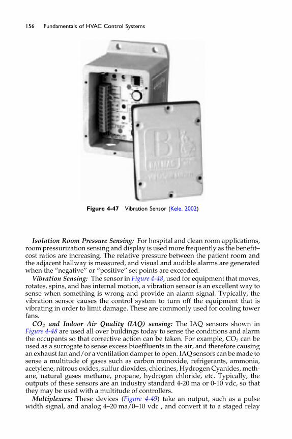
Figure 4-47 Vibration Sensor (Kele, 2002)
156 Fundamentals of HVAC Control Systems
Isolation Room Pressure Sensing: For hospital and clean room applications,roompressurization sensing and display is usedmore frequently as the benefit–cost ratios are increasing. The relative pressure between the patient room andthe adjacent hallway is measured, and visual and audible alarms are generatedwhen the “negative” or “positive” set points are exceeded.
Vibration Sensing: The sensor in Figure 4-48, used for equipment that moves,rotates, spins, and has internal motion, a vibration sensor is an excellent way tosense when something is wrong and provide an alarm signal. Typically, thevibration sensor causes the control system to turn off the equipment that isvibrating in order to limit damage. These are commonly used for cooling towerfans.
CO2 and Indoor Air Quality (IAQ) sensing: The IAQ sensors shown inFigure 4-48 are used all over buildings today to sense the conditions and alarmthe occupants so that corrective action can be taken. For example, CO2 can beused as a surrogate to sense excess bioeffluents in the air, and therefore causingan exhaust fan and/or a ventilation damper to open. IAQ sensors can bemade tosense a multitude of gases such as carbon monoxide, refrigerants, ammonia,acetylene, nitrous oxides, sulfur dioxides, chlorines, Hydrogen Cyanides, meth-ane, natural gases methane, propane, hydrogen chloride, etc. Typically, theoutputs of these sensors are an industry standard 4-20 ma or 0-10 vdc, so thatthey may be used with a multitude of controllers.
Multiplexers: These devices (Figure 4-49) take an output, such as a pulsewidth signal, and analog 4–20 ma/0–10 vdc , and convert it to a staged relay
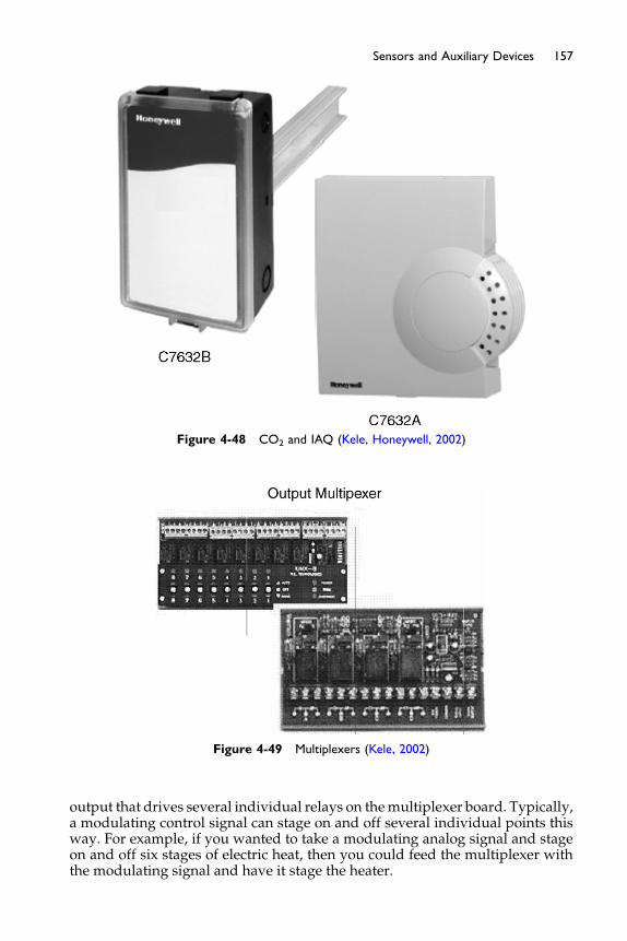
Figure 4-48 CO2 and IAQ (Kele, Honeywell, 2002)
Figure 4-49 Multiplexers (Kele, 2002)
157Sensors and Auxiliary Devices
output that drives several individual relays on themultiplexer board. Typically,a modulating control signal can stage on and off several individual points thisway. For example, if you wanted to take a modulating analog signal and stageon and off six stages of electric heat, then you could feed the multiplexer withthe modulating signal and have it stage the heater.
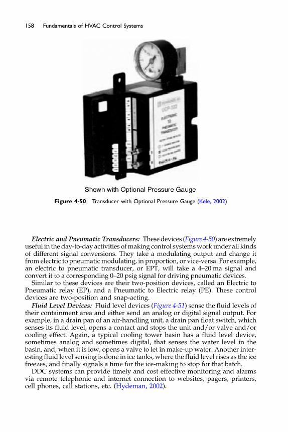
Figure 4-50 Transducer with Optional Pressure Gauge (Kele, 2002)
158 Fundamentals of HVAC Control Systems
Electric and Pneumatic Transducers: Thesedevices (Figure 4-50) are extremelyuseful in the day-to-day activities ofmaking control systemsworkunder all kindsof different signal conversions. They take a modulating output and change itfrom electric to pneumaticmodulating, in proportion, or vice-versa. For example,an electric to pneumatic transducer, or EPT, will take a 4–20 ma signal andconvert it to a corresponding 0–20 psig signal for driving pneumatic devices.
Similar to these devices are their two-position devices, called an Electric toPneumatic relay (EP), and a Pneumatic to Electric relay (PE). These controldevices are two-position and snap-acting.
Fluid Level Devices: Fluid level devices (Figure 4-51) sense the fluid levels oftheir containment area and either send an analog or digital signal output. Forexample, in a drain pan of an air-handling unit, a drain pan float switch, whichsenses its fluid level, opens a contact and stops the unit and/or valve and/orcooling effect. Again, a typical cooling tower basin has a fluid level device,sometimes analog and sometimes digital, that senses the water level in thebasin, and, when it is low, opens a valve to let in make-up water. Another inter-esting fluid level sensing is done in ice tanks, where the fluid level rises as the icefreezes, and finally signals a time for the ice-making to stop for that batch.
DDC systems can provide timely and cost effective monitoring and alarmsvia remote telephonic and internet connection to websites, pagers, printers,cell phones, call stations, etc. (Hydeman, 2002).
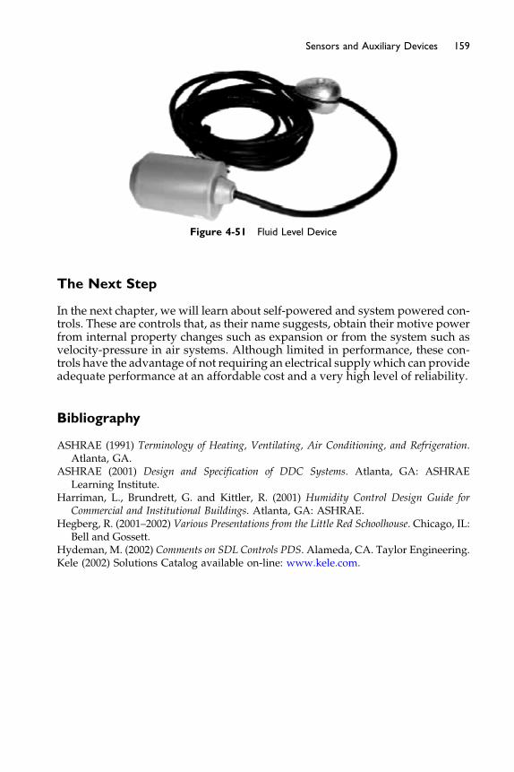
Figure 4-51 Fluid Level Device
159Sensors and Auxiliary Devices
The Next Step
In the next chapter, we will learn about self-powered and system powered con-trols. These are controls that, as their name suggests, obtain their motive powerfrom internal property changes such as expansion or from the system such asvelocity-pressure in air systems. Although limited in performance, these con-trols have the advantage of not requiring an electrical supplywhich can provideadequate performance at an affordable cost and a very high level of reliability.
Bibliography
ASHRAE (1991) Terminology of Heating, Ventilating, Air Conditioning, and Refrigeration.Atlanta, GA.
ASHRAE (2001) Design and Specification of DDC Systems. Atlanta, GA: ASHRAELearning Institute.
Harriman, L., Brundrett, G. and Kittler, R. (2001) Humidity Control Design Guide forCommercial and Institutional Buildings. Atlanta, GA: ASHRAE.
Hegberg, R. (2001–2002) Various Presentations from the Little Red Schoolhouse. Chicago, IL:Bell and Gossett.
Hydeman, M. (2002) Comments on SDL Controls PDS. Alameda, CA. Taylor Engineering.Kele (2002) Solutions Catalog available on-line: www.kele.com.
Chapter 5
Self- and System-powered Controls
Contents of Chapter 5
Study Objectives of Chapter 55.1 Principles of Operation – Self-powered Controls
5.2 Examples of Self-powered Controls 5.3 System-powered Controls The Next StepStudy Objectives of Chapter 5
Self-powered and system-powered controls are those that do not require anexternal power source such as electricity or pneumatic control air. This chap-ter explains how these devices work and where they are commonly used.
After studying this chapter, you should be able to understand:
The sources from which self-powered controls derive their control power.How a thermopile works.How air flow can bemodulated using self-powered variable volume diffusers.The advantages and disadvantages of system-powered controls.
5.1 Principles of Operation – Self-powered Controls
Self-powered controls are those that draw the energy needed for their opera-tion from the systems that they control or operate. They are commonly usedon small systems or individual units where they are more convenient and lesscostly because they do not require an external power source such as electricityor pneumatic control air.
The power source in self-powered devices is typically derived from:
� Electrical potential generated by a thermopile, which is a type of thermo-couple operating as a power source (like a battery). Like a thermocouple,the thermopile is composed of two dissimilar metals bonded together thatcreate voltage. The magnitude of the voltage varies with the temperatureto which the device is exposed. With thermocouples (Chapter 4), this effect
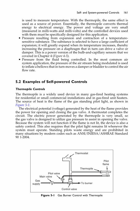
161Self- and System-powered Controls
is used to measure temperature. With the thermopile, the same effect isused as a source of power. Essentially, the thermopile converts thermalenergy to electrical energy. The power and voltage are very small(measured in milli-watts and milli-volts) and the controlled devices usedwith them must be specifically designed for this application.
� Pressure resulting from expansion and contraction of a temperature-sensitive substance. The substance is selected to have a large coefficient ofexpansion; it will greatly expand when its temperature increases, therebyincreasing the pressure on a diaphragm that in turn can drive a valve ordamper. This is a power version of the bulb-and-capillary sensors that wecovered in Chapter 4 (Figure 4-5).
� Pressure from the fluid being controlled. In the most common airsystem application, the pressure of the air stream being modulated is usedto inflate a bellows that in turnmoves a damper or bladder to control the airflow rate.
5.2 Examples of Self-powered Controls
Thermopile Controls
The thermopile is a widely used device in many gas-fired heating systemsfor residential or small commercial installations and in gas-fired unit heaters.The source of heat is the flame of the gas standing pilot light, as shown inFigure 5-1.The electrical potential (voltage) generated by the heat of the flame provides
the power for opening and closing the gas valve. A thermostat completes thecircuit. The electric power generated by the thermopile is very small, sothe gas valve is designed to utilize gas pressure to assist in opening the valve.Because the system will not function if the flame is not lit, the device is also asafety control. This also requires that the pilot light remains lit whenever thesystem must operate. Standing pilots waste energy and are prohibited inmany situations by modern codes such as ANSI/INIESA/ASHRAE Standard90 1-2004.
Thermostat
Thermopile
Pilotflame
Pilot valveMain valve
Gassupply
Control valve
To burner
Figure 5-1 Gas Burner Control with Thermopile
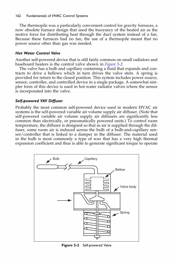
162 Fundamentals of HVAC Control Systems
The thermopile was a particularly convenient control for gravity furnaces, anow obsolete furnace design that used the buoyancy of the heated air as themotive force for distributing heat through the duct system instead of a fan.Because these furnaces had no fan, the use of a thermopile meant that nopower source other than gas was needed.
Hot Water Control Valve
Another self-powered device that is still fairly common on small radiators andbaseboard heaters is the control valve shown in Figure 5-2.
The valve has a bulb and capillary containing a fluid that expands and con-tracts to drive a bellows which in turn drives the valve stem. A spring isprovided for return to the closed position. This system includes power source,sensor, controller, and controlled device in a single package. A somewhat sim-pler form of this device is used in hot water radiator valves where the sensoris incorporated into the valve.
Self-powered VAV Diffuser
Probably the most common self-powered device used in modern HVAC airsystems is the self-powered variable air volume supply air diffuser. (Note thatself-powered variable air volume supply air diffusers are significantly lesscommon than electrically, or pneumatically powered units.) To control roomtemperature, the diffuser is designed so that as air is supplied through the dif-fuser, some room air is induced across the bulb of a bulb-and-capillary sen-sor/controller that is linked to a damper in the diffuser. The material usedin the bulb is most commonly a type of wax that has a very high thermalexpansion coefficient and thus is able to generate significant torque to operate
Bulb
Spring
Valve body
Bellow
Capillary
Figure 5-2 Self-powered Valve
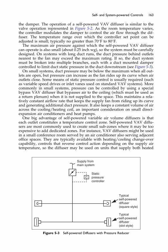
163Self- and System-powered Controls
the damper. The operation of a self-powered VAV diffuser is similar to thevalve operation represented in Figure 5-2. As the room temperature varies,the controller modulates the damper to control the air flow through the dif-fuser. The temperature range over which the controller set point can beadjusted is small; typically no greater than 70�F to 80�F.The maximum air pressure against which the self-powered VAV diffuser
can operate is also small (about 0.25 inch wg), so the system must be carefullydesigned. On systems with long duct runs, the duct pressure behind outletsnearest to the fan may exceed the maximum rating. If so, the duct systemmust be broken into multiple branches, each with a duct mounted dampercontrolled to limit duct static pressure in the duct downstream (see Figure 5-3).On small systems, duct pressure may be below the maximum when all out-
lets are open, but pressure can increase as the fan rides up its curve when airoutlets close. Some means of static pressure control is usually required (suchas variable speed drives or inlet vanes used on standard VAV systems). Morecommonly in small systems, pressure can be controlled by using a specialbypass VAV diffuser that bypasses air to the ceiling (which must be used asa return plenum) when it is not supplied to the space. This maintains a rela-tively constant airflow rate that keeps the supply fan from riding up its curveand generating additional duct pressure. It also keeps a constant volume of airacross the cooling/heating coil, an important consideration on small direct-expansion air conditioners and heat pumps.One big advantage of self-powered variable air volume diffusers is that
each outlet constitutes a temperature control zone. Self-powered VAV diffu-sers are most commonly used to create small sub-zones where it may be tooexpensive to add dedicated zones. For instance, VAV diffusers might be usedin a small conference room served by an air conditioner also serving adjacentoffice spaces. They are typically available with heating/cooling change-overcapability, controls that reverse control action depending on the supply airtemperature, so the diffuser may be used on units that supply both heated
Supply frommain system
Staticpressurecontroller
Typicalself-powereddiffuser(square style)
Typicalself-powereddiffuser(slot style)
C
Figure 5-3 Self-powered Diffusers with Pressure Reducer

Relocatablepartitions
Static pressurecontrol valve
Modular self-poweredoutlets
Figure 5-4 Modular Self-powered Outlets
164 Fundamentals of HVAC Control Systems
and cooled air. Where many small zones are desired (such as in an applicationwith many small private offices), VAV diffusers might be the best solutionbecause they are generally less expensive than using small individual stan-dard VAV boxes and conventional diffusers.
The self-powered boxes do not offer the control flexibility offered by othercontrol methods. Perhaps the most obvious is that the occupant does not havethe ability to change the set point. The set point can be changed but it requiresaccess to the diffuser on the ceiling and often removal of the face plate.Compared to other control systems, it also lacks functionality as there is no abil-ity for remote adjustment, night or unoccupied setback, or shut-off, or the abilityfor remote monitoring.
The limited pressure capacity and self-contained attributes can be attractivein specific situations. A simple example is a building which has many smallspaces and a high frequency of changes in layout (high churn rate). A systemsuch as shown in Figure 5-4 can provide consistent temperature control forvariable layouts. Changing layouts does not involve any change in wiring ortubing, and whatever the layout the space will contain its share of outlets eachwith internal control.
5.3 System-powered Controls
System-powered Air Valves
System-powered controls – devices that use supply air pressure as the powersource – are a variation on self-powered controls used on early constant airvolume (CAV) regulators and variable air volume boxes and diffusers. Theywere very popular in the late 1950s through 1970s, but they have largely beenreplaced by pneumatic, analog electronic, and digital controls in modern sys-tems. While attractive because they do not require any external power source,system-powered controls often require that duct static pressure be relativelyhigh (about 1 inch to 2 inch wg, depending on the manufacturer). This highpressure was standard on early high-pressure VAV systems but not on mod-ern, low- and medium-pressure systems designed to minimize fan energy.
Some system-poweredVAVboxes andVAVdiffusers aredesigned for lowpres-sure systems, requiring an inlet pressure of only about 0.5 inch to 0.75 inch wg,
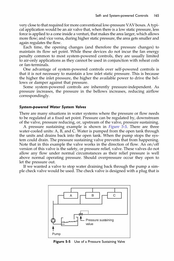
165Self- and System-powered Controls
very close to that required formore conventional low-pressure VAVboxes. A typi-cal application would be an air valve that, when there is a low static pressure, lessforce is applied to a cone inside a venturi, that makes the area larger, which allowsmore flow; and vice versa, during higher static pressure, the area gets smaller andagain regulates the flow.Each time, the opening changes (and therefore the pressure changes) to
maintain its flow set point. While these devices do not incur the fan energypenalty common to most system-powered controls, they are usually limitedto air-only applications as they cannot be used in conjunction with reheat coilsor fan-terminals.One advantage of system-powered controls over self-powered controls is
that it is not necessary to maintain a low inlet static pressure. This is becausethe higher the inlet pressure, the higher the available power to drive the bel-lows or damper against that pressure.Some system-powered controls are inherently pressure-independent. As
pressure increases, the pressure in the bellows increases, reducing airflowcorrespondingly.
System-powered Water System Valves
There are many situations in water systems where the pressure or flow needsto be regulated at a fixed set point. Pressure can be regulated by, downstreamof the valve, pressure reducing, or, upstream of the valve, pressure sustaining.A pressure sustaining example is shown in Figure 5-5. There are three
water-cooled units: A, B, and C. Water is pumped from the open tank throughthe units and drains back into the open tank. When the pump stops the sys-tem could drain. The pressure sustaining valve prevents that from happening.Note that in this example the valve works in the direction of flow. An on/offversion of this valve is the safety, or pressure relief, valve. These valves do notallow any flow under normal circumstances as their relief pressure is wellabove normal operating pressure. Should overpressure occur they open tolet the pressure out.If we wanted a valve to stop water draining back through the pump a sim-
ple check valve would be used. The check valve is designed with a plug that is
Pressure sustainingvalue
A B C
Pump
Figure 5-5 Use of a Pressure Sustaining Valve

Coil
PRVIsolation
valve
A
B
Wordingcoilisolation value
Figure 5-6 PRV and Control Valve Package
166 Fundamentals of HVAC Control Systems
free to open easily with flow in the forward direction but to close completely ifthe flow reverses.
Maintaining the pressure downstream at a lower pressure is the task of apressure reducing valve. Some equipment, commercial dishwashers for exam-ple, work best with a constant water pressure much lower than the typical citywater supply. They would have a pressure reducing valve in their supplypipe to maintain the constant, lower, pressure.
Do you remember the section back in Chapter 3 on control valves and thechallenge of varying pressure causing varying behavior? One way out ofthe problem is the have a pressure reducing valve in front of the control valveas Figure 5-6. The two valves can be purchased as a single, factory producedunit. The pressure reducing valve (PRV) maintains a steady pressure on thedownstream side of the control valve. The pressure reducing valve effectivelyabsorbs all changes in resistance due to the changes in flow (volume � √DP)and control valve position. The result is a control valve that performs veryclose to its design characteristic.
The Next Step
In the next chapter, we will learn about electric control systems that are usedprimarily on simple systems, such as simple on/off control of fans and onsmall packaged HVAC equipment.
Chapter 6
Electric Controls
Contents of Chapter 6
Study Objectives of Chapter 66.1 Sensors
6.2 Controllers, Two-position 6.3 Controllers, Modulating 6.4 Example Application 6.5 Actuators 6.6 Auxiliary Devices The Next StepBibliographyStudy Objectives of Chapter 6
Electric controls typically use 24 Volts ac, as a power source and use only con-tact closures (open-closed) and varying resistance (100–20,000 ohms), controllogic; they do not use analog or digital electronics. The most common andbasic temperature controller – the simple two-position thermostat – is anexample of an electric control.After studying this chapter, you should:
Understand how electric controllers (stats) are used to provide two-positioncontrol.
Understand how modulating controls work using bridge circuits.Understand the difference between two-position, floating, and modulating
actuators.Know how to use electric controls in common HVAC applications.
6.1 Sensors
The temperature sensors most commonly used with two-position electric con-trols are the bimetallic strip, mercury switch, and the bulb-and-capillary, orremote bulb sensor, as shown in Figure 6-1. A bellows-style sensor is commonlyused for modulating electric controls.
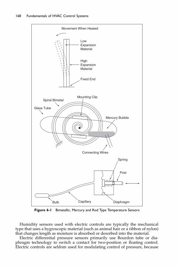
Mounting Clip
Movement When Heated
LowExpansionMaterial
HighExpansionMaterial
Fixed End
Connecting Wires
Mercury Bubble
Spring
Post
DiaphragmCapillaryBulb
Spiral Bimetal
Glass Tube
Figure 6-1 Bimetallic, Mercury and Rod Type Temperature Sensors
168 Fundamentals of HVAC Control Systems
Humidity sensors used with electric controls are typically the mechanicaltype that uses a hygroscopic material (such as animal hair or a ribbon of nylon)that changes length as moisture is absorbed or desorbed into the material.
Electric differential pressure sensors primarily use Bourdon tube or dia-phragm technology to switch a contact for two-position or floating control.Electric controls are seldom used for modulating control of pressure, because

169Electric Controls
pressure is a fast-moving variable and usually requires a fast-acting signal.Similarly, flow status sensors are generally two-position switches using pad-dles or sails. (See Chapter 4 for a detailed description of sensors.)
6.2 Controllers, Two-position
Electric controls are most commonly two-position, using thermostats, humidi-stats, or pressure-stats wherein the controlled variable is sensed and com-pared to set point and a contact is opened and closed accordingly.Figure 6-2 shows examples of how two-position and modulating controls
are wired. In the first line, a cooling thermostat (one whose contact closes ona rise in temperature above set point) turns on and off a fan. If the fan waspowered through the thermostat (if the round symbol in the figure was thefan motor itself), the thermostat would be called a line-voltage thermostatand its contact must be rated for the voltage and current required by themotor. A motor as large as about 1 horsepower can be controlled in this man-ner, as long as the contacts in the stat can handle the amperage and in-rushcurrent. Motors larger than about ½ hp typically have motor starters, withoverload protection, and the round symbol in the figure would represent astarter coil or relay whose contact is wired to energize the starter coil.The bottom line of Figure 6-2 shows a floating controller that opens and closes
a valve or damper through its actuator. When the controller senses that the con-trolled variable is above set point, the upper contact closes and opens the valveor damper. The actuator drives all theway open or closed, through its full strokelength, in a time period (usually 10–90 seconds). When the controlled variable isbelow set point, the lower contact closes, driving the valve or damper closed.When the controlled variable is within the controller differential, the switch isin the neutral position and the valve or damper stays in its last position. If youare not sure of how this works look back at Chapter 1, Section 1.4.Packaged HVAC equipment has traditionally used electric controls,
although many newer systems are supplemented with analog electronic or
CONTROL VOLTAGE
Coolingthermostat
Fan motoror
starter coil
NEUTRALOPEN
CLOSE
Damper orvalve actuator
Floatingcontroller
Figure 6-2 Typical Two-position and Floating Electric Controls
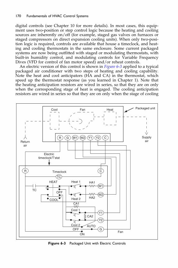
170 Fundamentals of HVAC Control Systems
digital controls (see Chapter 10 for more details). In most cases, this equip-ment uses two-position or step control logic because the heating and coolingsources are inherently on/off (for example, staged gas valves on furnaces orstaged compressors on direct expansion cooling units). When only two-posi-tion logic is required, controls are available that house a timeclock, and heat-ing and cooling thermostats in the same enclosure. Some current packagedsystems are now being outfitted with staged or modulating thermostats, withbuilt-in humidity control, and modulating controls for Variable FrequencyDives (VFD for control of fan motor speed) and/or reheat controls.
An electric version of this control is shown in Figure 6-3 applied to a typicalpackaged air conditioner with two steps of heating and cooling capability.Note the heat and cool anticipators (HA and CA) in the thermostat, whichspeed up the thermostat response (as you learned in Chapter 1). Note thatthe heating anticipation resistors are wired in series, so that they are on onlywhen the corresponding stage of heat is engaged. The cooling anticipationresistors are wired in series so that they are on only when the stage of cooling
R G W1 W2 Y2Y1 C
R
TC
TC
C
W1
W2
Y1
Y2
G
OFF
OFF
ON
AUTO
Supplyair
Cool Fan Heat
HEAT
COOL
Returnair
Electrictimeclock/T’stat
Timeclock
Heat 1
Cool 1
Cool 2
CA1
CA2
HA2
HA1
Fan
Packaged unit
Heat 2
Figure 6-3 Packaged Unit with Electric Controls

171Electric Controls
is off, and you are in cooling mode. The cooling resistor effect is thus to makethe thermostat think the temperature is rising more quickly that it really isand bring on the cooling earlier than if there were no anticipator heater. Notethat the anticipation heater resistors turn off heating more quickly but thecooling anticipator resistors turn on the cooling more quickly. Stage 2 coolingresistor is only on when it is in Stage 1 cooling and the second stage contacthas not been made.The controls in the package unit are not shown; these are factory mounted
and wired by the manufacturer. Power is supplied to the packaged unit.A 24 volt output transformer in the package unit provides power, via term-inals R and C, to the electric timeclock/thermostat control circuit. Only theexternal devices and wiring need be shown with packaged unit controls. Man-ufacturers’ drawings, provided with the unit, typically attached to the insideof access panels, show the details of the packaged controls.Electric timeclock/thermostats are being used less and less. They have been
replaced by programmable “electronic” timeclock/thermostats that are lessexpensive, more compact, are arguably easier to use, and, most importantly,have additional features such as timed override, ventilation control, cascadedhumidity control, occupied and un-occupied set points, and set point setback/setup capability. These added features simplify the control design signifi-cantly by eliminating additional components and wiring. The wiring of a pro-grammable thermostat looks exactly the same as an electric one, except thedevices in the controller itself are electronic rather than electric.Step control is accomplished by typically usingmulti-stage controllers, which
are basically a series of two-position controllers using the same sensor. Two andsometimes three stages of control are available. If more stages are required (forexample to control a multi-stage refrigeration compressor), a stepping switchcan be used (see Figure 6-4). It consists of a group of cam-operated switchesmounted in a common enclosure. The camshaft is driven by a motor, controlledby amodulating controller. In effect, the stepping switch converts a modulatingcontroller into a step controller. Angular adjustment of the cams allows the unitto close contacts one at a time until all are closed, or in sequence one at a time.
6.3 Controllers, Modulating
Electric controls are also used for truemodulating control using theWheatstonebridge, often referred to as a bridge circuit, shown in Figure 6-4. The bridge cir-cuit consists of four resistors connected in a loop, as shown in the figure. Apower source is connected across two diagonally opposite terminals. The othertwo terminals are connected to a load that may be a controlled device or mayprovide a modulating signal to an amplifying controller. The bridge circuit isused to send a varying output voltage to the load by varying the resistances.The bridge circuit can be analyzed using Ohm’s law (V ¼ IR), which was
introduced in Chapter 2. We know that the voltage drop through R2 and R3must equal the voltage of the power source, typically 24 V or sometimes120 V. Similarly, the voltage drop through R1 and R4 must equal this samevoltage. We also know that the current through R2 is the same as that throughR3 and the current through R1 is the same as that through R4. Expressingthese knowns using Ohm’s law (this is left as an extra exercise for the reader),

Cam shaft
Power
To loads
Figure 6-4 Stepping Switch
172 Fundamentals of HVAC Control Systems
we can derive the following expression for the voltage across the outputterminals:
V0 ¼ VpR2
R2þ R3� R1
R1þ R4
� �
ðEquation 6-1Þ
where V0 is the output voltage and Vp is the voltage of the power source.As this equation shows, varying any of the four resistors can vary the outputvoltage. If R2 is equal to R1, and R3 is equal to R4, the circuit would be bal-anced and, as can be seen from Equation 6-1, the output voltage would be zero.The output voltage is always less than the input voltage.
The bridge can be used in an electric controller as shown in Figure 6-6. Thesensor is a variable resistor (such as a bellows modulating a potentiometer).The set point is adjusted with another potentiometer in the same part of thebridge circuit. To calibrate the controller when the sensor drifts, a third poten-tiometer is used, as shown in the figure. A more detailed example of how thisbridge circuit is used with an actuator is discussed in the next section.
Three types of actuators are commonly used with electric controllers: pro-portional (modulating), floating and two-position.
The proportionally controlled electric actuator is used in a bridge circuit(physical characteristics of which described in the previous section) to drive a
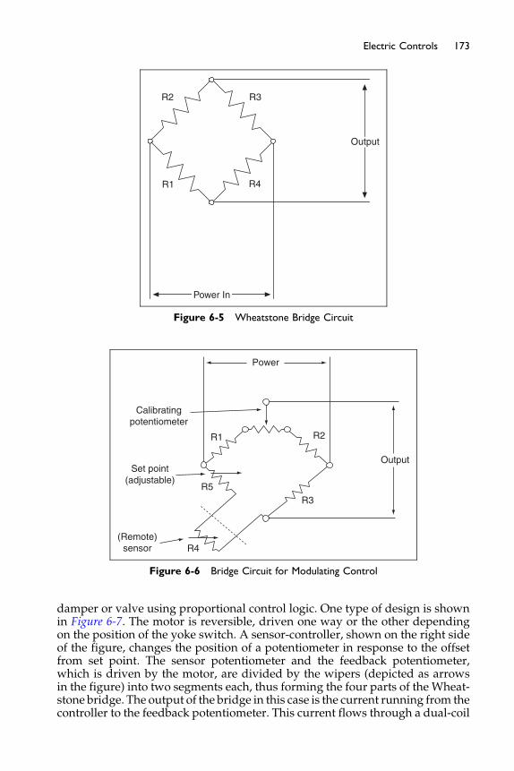
Power In
R1
R2 R3
R4
Output
Figure 6-5 Wheatstone Bridge Circuit
R1
R3
R4
R5
R2
Calibratingpotentiometer
Set point(adjustable)
(Remote)sensor
Power
Output
Figure 6-6 Bridge Circuit for Modulating Control
173Electric Controls
damper or valve using proportional control logic. One type of design is shownin Figure 6-7. The motor is reversible, driven one way or the other dependingon the position of the yoke switch. A sensor-controller, shown on the right sideof the figure, changes the position of a potentiometer in response to the offsetfrom set point. The sensor potentiometer and the feedback potentiometer,which is driven by the motor, are divided by the wipers (depicted as arrowsin the figure) into two segments each, thus forming the four parts of the Wheat-stone bridge. The output of the bridge in this case is the current running from thecontroller to the feedback potentiometer. This current flows through a dual-coil
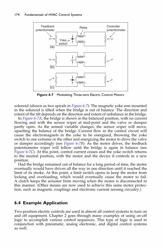
Feedbackpotentiometer
Yokeswitch
(a)
(b)
(c)
Controllerpotentiometer
Relay
Figure 6-7 Modulating Three-wire Electric Control Motors
174 Fundamentals of HVAC Control Systems
solenoid (shown as two spirals in Figure 6-7). The magnetic yoke arm mountedin the solenoid is tilted when the bridge is out of balance. The direction andextent of the tilt depends on the direction and extent of unbalance in the bridge.
In Figure 6-7A, the bridge is shown in the balanced position, with no currentflowing and with the sensor wiper at mid-point and the valve or damperpartly open. As the sensed variable changes, the sensor wiper will move,upsetting the balance of the bridge. Current flow in the control circuit willcause the electromagnets in the yoke to be energized, throwing the yokeswitch to one extreme or the other and energizing the motor to drive the valveor damper accordingly (see Figure 6-7B). As the motor drives, the feedbackpotentiometer wiper will follow until the bridge is again in balance (seeFigure 6-7C). At this point, control current ceases and the yoke switch returnsto the neutral position, with the motor and the device it controls in a newposition.
Had the bridge remained out of balance for a long period of time, the motoreventually would have driven all the way in one direction until it reached thelimit of its stroke. At this point, a limit switch opens to keep the motor fromlocking and overloading, which would eventually cause the motor to fail.A clutch keeps the actuator from moving when the motor is disconnected inthis manner. (Other means are now used to achieve this same motor protec-tion, such as magnetic couplings and electronic current sensing circuitry.)
6.4 Example Application
Two-position electric controls are used in almost all control systems to turn onand off equipment. Chapter 2 goes through many examples of using on-offlogic to accomplish various control sequences. This type of logic is used inconjunction with pneumatic, analog electronic, and digital control systemsas well.
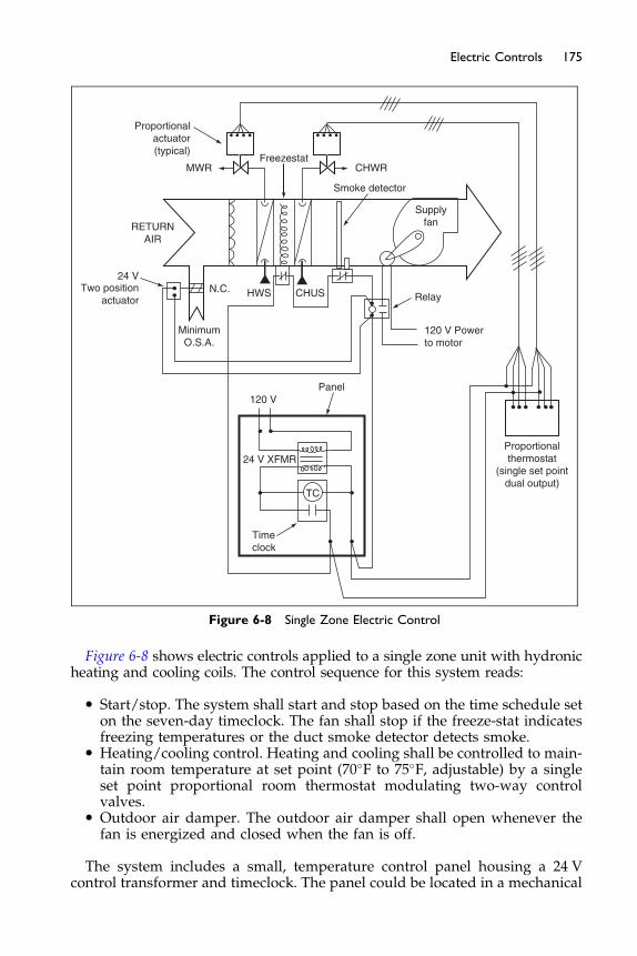
TC
24 V XFMR
24 VTwo position
actuator
Proportionalactuator(typical)
120 V
Timeclock
HWS CHUS
Freezestat
Smoke detector
SupplyfanRETURN
AIR
N.C.
CHWRMWR
120 V Powerto motor
MinimumO.S.A.
Relay
Proportionalthermostat
(single set pointdual output)
Panel
Figure 6-8 Single Zone Electric Control
175Electric Controls
Figure 6-8 shows electric controls applied to a single zone unit with hydronicheating and cooling coils. The control sequence for this system reads:
� Start/stop. The system shall start and stop based on the time schedule seton the seven-day timeclock. The fan shall stop if the freeze-stat indicatesfreezing temperatures or the duct smoke detector detects smoke.
� Heating/cooling control. Heating and cooling shall be controlled to main-tain room temperature at set point (70�F to 75�F, adjustable) by a singleset point proportional room thermostat modulating two-way controlvalves.
� Outdoor air damper. The outdoor air damper shall open whenever thefan is energized and closed when the fan is off.
The system includes a small, temperature control panel housing a 24 Vcontrol transformer and timeclock. The panel could be located in a mechanical
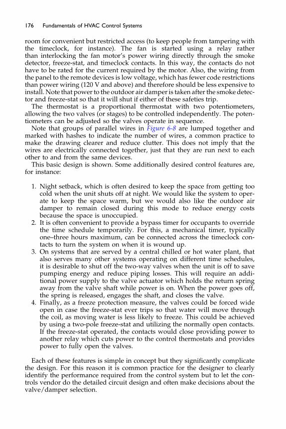
176 Fundamentals of HVAC Control Systems
room for convenient but restricted access (to keep people from tampering withthe timeclock, for instance). The fan is started using a relay ratherthan interlocking the fan motor’s power wiring directly through the smokedetector, freeze-stat, and timeclock contacts. In this way, the contacts do nothave to be rated for the current required by the motor. Also, the wiring fromthe panel to the remote devices is low voltage, which has fewer code restrictionsthan power wiring (120 V and above) and therefore should be less expensive toinstall. Note that power to the outdoor air damper is taken after the smokedetec-tor and freeze-stat so that it will shut if either of these safeties trip.
The thermostat is a proportional thermostat with two potentiometers,allowing the two valves (or stages) to be controlled independently. The poten-tiometers can be adjusted so the valves operate in sequence.
Note that groups of parallel wires in Figure 6-8 are lumped together andmarked with hashes to indicate the number of wires, a common practice tomake the drawing clearer and reduce clutter. This does not imply that thewires are electrically connected together, just that they are run next to eachother to and from the same devices.
This basic design is shown. Some additionally desired control features are,for instance:
1. Night setback, which is often desired to keep the space from getting toocold when the unit shuts off at night. We would like the system to oper-ate to keep the space warm, but we would also like the outdoor airdamper to remain closed during this mode to reduce energy costsbecause the space is unoccupied.
2. It is often convenient to provide a bypass timer for occupants to overridethe time schedule temporarily. For this, a mechanical timer, typicallyone–three hours maximum, can be connected across the timeclock con-tacts to turn the system on when it is wound up.
3. On systems that are served by a central chilled or hot water plant, thatalso serves many other systems operating on different time schedules,it is desirable to shut off the two-way valves when the unit is off to savepumping energy and reduce piping losses. This will require an addi-tional power supply to the valve actuator which holds the return springaway from the valve shaft while power is on. When the power goes off,the spring is released, engages the shaft, and closes the valve.
4. Finally, as a freeze protection measure, the valves could be forced wideopen in case the freeze-stat ever trips so that water will move throughthe coil, as moving water is less likely to freeze. This could be achievedby using a two-pole freeze-stat and utilizing the normally open contacts.If the freeze-stat operated, the contacts would close providing power toanother relay which cuts power to the control thermostats and providespower to fully open the valves.
Each of these features is simple in concept but they significantly complicatethe design. For this reason it is common practice for the designer to clearlyidentify the performance required from the control system but to let the con-trols vendor do the detailed circuit design and often make decisions about thevalve/damper selection.

177Electric Controls
6.5 Actuators
Electric actuators may be a solenoid for two-position or motor driven for two-position or modulating control. Electrical actuators are available in two styles:direct-coupled actuators that directly connect without linkages to the con-trolled device (such as a valve or damper); and a general purpose, foot-mounted actuator that must be connected to the controlled device by linkages.Actuators can be spring return or non-spring return. For valves that require
the stem to be raised and lowered, typical for a globe valve, the actuator mustprovide a linear movement, hence they are called linear actuators. The linearactuator must be able to apply an adequate force to operate the valve. Theforce is in pounds force, abbreviated lbf, In most situations closing off againstsystem pressure is the peak challenge and larger actuators will close offagainst higher differential pressures.Rotary direct-coupled actuators are usually limited to medium-size valves
and dampers requiring a medium amount of torque. They may either fit overthe shaft and rotate or have a short arm stroke of between ½ to 1½ inches. Forlarger strokes, general-purpose actuators with linkages can stroke muchgreater distances. Direct-coupled actuators are usually less expensive andmore reliable than the general-purpose actuator because of fewer movingparts and the linkage is eliminated. They are easy and quick to install, requireno special tools, rarely require adjustments, and have low power needs.General-purpose rotary actuators are useful when space requirements are
limited, when greater torque is required, and larger strokes are needed. Thetorque ranges of general-purpose actuators are about the same as the directcoupled, about 10.00 inch lbf, but multiple actuators can be linked togetheron a shaft or through a linkage arrangement in order to overcome large torqueforces. In addition, these actuators have been in the marketplace for a longtime and they are therefore, still in use for older retrofits.Actuators are available with and without spring return. Spring return is
used to provide a normal position of the valve or damper when power isremoved (see Chapter 1). Actuators without spring return remain in their lastposition when power is removed. Many non-spring return actuators have amanual positioner device that will allow opening or closing of the actuatorwhen power is lost. If no manual positioning device is available on the actua-tor, then manual valves or dampers should surround the controlled device sothat the normal position can be open, and, if need be, manual devices can beclosed off.System gain is affected by the motor speed. Generally, these motors take 30
to 150 seconds (often adjustable in a range which may go up to 300 seconds ormore) to travel from one extreme to the other. Motors of this type are made foruse primarily with 24 V ac power sources, and, less commonly, with 110 Vsources.Floating-control actuators are similar to proportional actuators except they
do not require the feedback potentiometer. (A feedback potentiometer canbe added for monitoring purposes.) They are reversible and include limitswitches as above.With the typical electric actuator, the power source to the motor and the
control power are the same. For this type of actuator, spring return cannot

178 Fundamentals of HVAC Control Systems
be used directly; the actuator cannot have a normal position. This is becauseif the actuator had a spring return, the damper would not remain fixed whenthe yoke or controller was in the neutral position. If spring return is requiredfor a given control application, a special type of electric actuator must beused. These actuators have a separate power supply from the control signal.This second power supply powers a “clutch” that disengages the springfrom the actuator when the power is on. When power is removed, the springengages, returning the actuator to its normal position regardless of the con-trol signal. This is one of the most widely used actuators in the marketplacetoday.
Two-position actuators generally are unidirectional with spring return, ornon-spring return. Two-position motors are available for various voltages,most commonly 24/120 V ac but also for higher voltages such as 480 V accommonly used to power large motors. These high voltage actuators arehandy for opening dampers at fan inlets or discharges, with the actuatorwired to the power circuit feeding the fan motor in parallel with the motor.In current applications, it is preferred to use transformers to step-down thevoltage to 24 or 120 VAC in order to drive actuators. Normally actuators areslow moving, typically 60–150 seconds for their full travel, but for some appli-cations it may be desirable to have them open and close faster, such as 5–15seconds. One popular use for these actuators is opening and closing smokedampers for life safety systems.
Auxiliary position switches are a common accessory to electric actuators.They close or open a contact when the actuator is in a certain position. Gener-ally the position is adjustable, although on some actuators the position is fixedto the end-positions, fully open or fully closed. One, two, and sometimes threeauxiliary switches are typically available as options. As examples of its use,the auxiliary switch could be wired to start a fan only after a damper is nearlyall the way open, or it could be used to turn off a pump when a valve is nearlyfully closed.
6.6 Auxiliary Devices
Auxiliary devices used with electric controls were also discussed in Chapter 4.The main accessories for actuators are for chaining controls, or the provision offeedback. For example, in an earlier chapter we were discussing the use of adamper end switch to switch on the fan once the damper had opened. For thisa single pole end switch would be required. If, instead we wanted feedback asto the damper position, we could specify a 5 k Ohm (5,000 Ohm), or 10 k poten-tiometer. This is a resistance coil with a slider which provides a resistance from0 to 5 k ohms as the shaft rotates.
For situations where the damper actuator will be out in the weather, aweather shield may be specified.
Sometimes it will take multiple actuators to drive a damper; tandem-mounting kits can be used for this requirement. Also, as a damper ages, itsometimes requires more torque to operate because of wear, dirt, or other pro-blems and may require more torque that can be supplied by multipleactuators.

179Electric Controls
While it is possible to control more complicated systems such as variable airvolume systems using electric controls, more commonly these systems arecontrolled by pneumatic, analog electronic, or digital controls, and are thesubjects of the following chapters.
The Next Step
In the next chapter, we will learn about pneumatic controls. Pneumatic con-trols were once the most commonly used controls in non-residential applica-tions, but they are largely being replaced by modern analog electronic anddigital controls. Nevertheless, understanding pneumatic controls is importantbecause they are still heavily used in existing buildings.
Bibliography
Honeywell Controls (2001) ACS Specialist CD-Rom. Minneapolis, MN.
Chapter 7
Pneumatic Controls
Contents of Chapter 7
Study Objectives of Chapter 77.1 Principles of Operation
7.2 Sensors 7.3 Controllers 7.4 Actuators 7.5 Auxiliary Devices 7.6 Compressed Air Supply 7.7 Example Applications The Next StepBibliographyStudy Objectives of Chapter 7
Pneumatic controls, which use compressed air as the power source, are verysimple and inherently analog, making them ideal for controlling temperature,humidity, and pressure. As such, they were once the most common controlsused in non-residential buildings, but they are rapidly being replaced by morecapable and flexible analog electronic and digital controls (covered in the nexttwo chapters). Pneumatic controls are still used commonly at the zone level(for example at VAV and CAV boxes, reheat coils, and fan-coils) and pneumaticactuators at valves and dampers are still commonly used in large digital controlsystems due to their reliability and cost. The movement of higher torque valvesand dampers is especially cost effective using pneumatic actuators. There is alsoa very large installed base of pneumatic controls in existing buildings. For thesereasons, it is important to understand how pneumatic controls work.
After studying this chapter, you should:
Understand the force-balance principle and how it is used in pneumaticcontrols.
Understand how temperature and pressure work in pneumatic controlsystems.
Understand how spring ranges can be used to sequence valves anddampers.
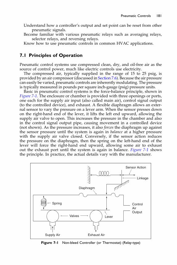
181Pneumatic Controls
Understand how a controller’s output and set point can be reset from otherpneumatic signals.
Become familiar with various pneumatic relays such as averaging relays,selector relays, and reversing relays.
Know how to use pneumatic controls in common HVAC applications.
7.1 Principles of Operation
Pneumatic control systems use compressed clean, dry, and oil-free air as thesource of control power, much like electric controls use electricity.The compressed air, typically supplied in the range of 15 to 25 psig, is
provided by an air compressor (discussed in Section 7.6). Because the air pressurecan easily be varied, pneumatic controls are inherentlymodulating. The pressureis typically measured in pounds per square inch-gauge (psig) pressure units.Basic in pneumatic control systems is the force-balance principle, shown in
Figure 7-1. The enclosure or chamber is provided with three openings or ports,one each for the supply air input (also called main air), control signal output(to the controlled device), and exhaust. A flexible diaphragm allows an exter-nal sensor to vary the pressure on a lever arm. When the sensor presses downon the right-hand end of the lever, it lifts the left end upward, allowing thesupply air valve to open. This increases the pressure in the chamber and alsoin the control signal output pipe, causing movement in a controlled device(not shown). As the pressure increases, it also forces the diaphragm up againstthe sensor pressure until the system is again in balance at a higher pressurewith the supply air valve closed. Conversely, if the sensor action reducesthe pressure on the diaphragm, then the spring on the left-hand end of thelever will force the right-hand end upward, allowing some air to exhaustout the exhaust port until the system is again in balance. Figure 7-1 showsthe principle. In practice, the actual details vary with the manufacturer.
Spring
Valves Lever
ControlAirOutput
Linkage
Sensor Action
Diaphragm
Supply Air Exhaust Air
Figure 7-1 Non-bleed Controller (or Thermostat) (Relay-type)
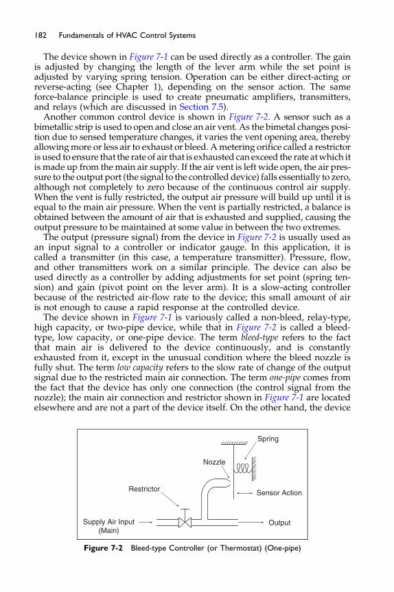
182 Fundamentals of HVAC Control Systems
The device shown in Figure 7-1 can be used directly as a controller. The gainis adjusted by changing the length of the lever arm while the set point isadjusted by varying spring tension. Operation can be either direct-acting orreverse-acting (see Chapter 1), depending on the sensor action. The sameforce-balance principle is used to create pneumatic amplifiers, transmitters,and relays (which are discussed in Section 7.5).
Another common control device is shown in Figure 7-2. A sensor such as abimetallic strip is used to open and close an air vent. As the bimetal changes posi-tion due to sensed temperature changes, it varies the vent opening area, therebyallowingmore or less air to exhaust or bleed. Ametering orifice called a restrictoris used to ensure that the rate of air that is exhausted can exceed the rate atwhich itis made up from themain air supply. If the air vent is left wide open, the air pres-sure to the output port (the signal to the controlled device) falls essentially to zero,although not completely to zero because of the continuous control air supply.When the vent is fully restricted, the output air pressure will build up until it isequal to the main air pressure. When the vent is partially restricted, a balance isobtained between the amount of air that is exhausted and supplied, causing theoutput pressure to be maintained at some value in between the two extremes.
The output (pressure signal) from the device in Figure 7-2 is usually used asan input signal to a controller or indicator gauge. In this application, it iscalled a transmitter (in this case, a temperature transmitter). Pressure, flow,and other transmitters work on a similar principle. The device can also beused directly as a controller by adding adjustments for set point (spring ten-sion) and gain (pivot point on the lever arm). It is a slow-acting controllerbecause of the restricted air-flow rate to the device; this small amount of airis not enough to cause a rapid response at the controlled device.
The device shown in Figure 7-1 is variously called a non-bleed, relay-type,high capacity, or two-pipe device, while that in Figure 7-2 is called a bleed-type, low capacity, or one-pipe device. The term bleed-type refers to the factthat main air is delivered to the device continuously, and is constantlyexhausted from it, except in the unusual condition where the bleed nozzle isfully shut. The term low capacity refers to the slow rate of change of the outputsignal due to the restricted main air connection. The term one-pipe comes fromthe fact that the device has only one connection (the control signal from thenozzle); the main air connection and restrictor shown in Figure 7-1 are locatedelsewhere and are not a part of the device itself. On the other hand, the device
Supply Air Input(Main)
Restrictor
Nozzle
Spring
Sensor Action
Output
Figure 7-2 Bleed-type Controller (or Thermostat) (One-pipe)
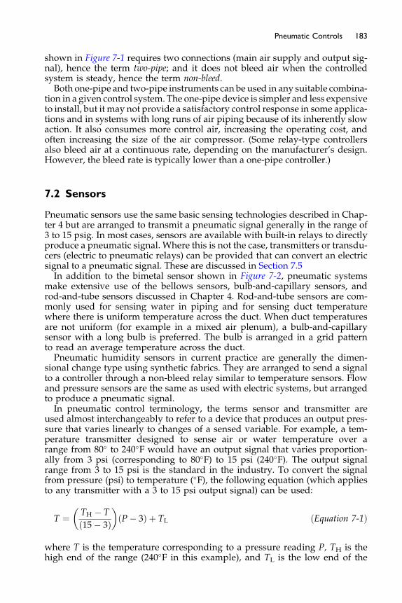
183Pneumatic Controls
shown in Figure 7-1 requires two connections (main air supply and output sig-nal), hence the term two-pipe; and it does not bleed air when the controlledsystem is steady, hence the term non-bleed.Both one-pipe and two-pipe instruments can be used in any suitable combina-
tion in a given control system. The one-pipe device is simpler and less expensiveto install, but it may not provide a satisfactory control response in some applica-tions and in systems with long runs of air piping because of its inherently slowaction. It also consumes more control air, increasing the operating cost, andoften increasing the size of the air compressor. (Some relay-type controllersalso bleed air at a continuous rate, depending on the manufacturer’s design.However, the bleed rate is typically lower than a one-pipe controller.)
7.2 Sensors
Pneumatic sensors use the same basic sensing technologies described in Chap-ter 4 but are arranged to transmit a pneumatic signal generally in the range of3 to 15 psig. In most cases, sensors are available with built-in relays to directlyproduce a pneumatic signal. Where this is not the case, transmitters or transdu-cers (electric to pneumatic relays) can be provided that can convert an electricsignal to a pneumatic signal. These are discussed in Section 7.5In addition to the bimetal sensor shown in Figure 7-2, pneumatic systems
make extensive use of the bellows sensors, bulb-and-capillary sensors, androd-and-tube sensors discussed in Chapter 4. Rod-and-tube sensors are com-monly used for sensing water in piping and for sensing duct temperaturewhere there is uniform temperature across the duct. When duct temperaturesare not uniform (for example in a mixed air plenum), a bulb-and-capillarysensor with a long bulb is preferred. The bulb is arranged in a grid patternto read an average temperature across the duct.Pneumatic humidity sensors in current practice are generally the dimen-
sional change type using synthetic fabrics. They are arranged to send a signalto a controller through a non-bleed relay similar to temperature sensors. Flowand pressure sensors are the same as used with electric systems, but arrangedto produce a pneumatic signal.In pneumatic control terminology, the terms sensor and transmitter are
used almost interchangeably to refer to a device that produces an output pres-sure that varies linearly to changes of a sensed variable. For example, a tem-perature transmitter designed to sense air or water temperature over arange from 80� to 240�F would have an output signal that varies proportion-ally from 3 psi (corresponding to 80�F) to 15 psi (240�F). The output signalrange from 3 to 15 psi is the standard in the industry. To convert the signalfrom pressure (psi) to temperature (�F), the following equation (which appliesto any transmitter with a 3 to 15 psi output signal) can be used:
T ¼ TH � T
ð15� 3Þ� �
ðP� 3Þ þ TL ðEquation 7-1Þ
where T is the temperature corresponding to a pressure reading P, TH is thehigh end of the range (240�F in this example), and TL is the low end of the

184 Fundamentals of HVAC Control Systems
range (80�F in this example). The temperature from this transmittercorresponding to a 10 psig signal would then be:
T ¼ 240� 80
12
0
@
1
Að10� 3Þ þ 80
¼ 173�F
To make this conversion easier, manufacturers typically provide conversioncharts with the transmitter. If the temperature is displayed (such as on the faceof a control panel), a pressure gaugewould be connected to the signal fittedwitha scale reading in “Deg. F” rather than psig. Pneumatic gauges often comewith several scales designed to be used with standard transmitter ranges (forexample, 35�F to 135�F, 50�F to 100�F, 0� to 100�F, 20% to 80% RH, etc.).
7.3 Controllers
Most pneumatic controllers (historically called receiver/controllers) are of thenon-bleed type using force/balance principles described previously. The basicand by far the most commonly used controller is proportional-only. But, spe-cial controllers or relays are available that can produce proportional-plus-integral (PI) control logic. The output of pneumatic controls typically variesfrom 3 to 15 psig nominally, but the actual output can vary from zero psigup to the pressure of the main air supply.
The basic receiver/controller is commonly shown as in Figure 7-3A withthree air connections (ports) for main air supply, sensor input connection froma pneumatic transmitter, and output to the controlled device. The labelingused to mark these ports varies by manufacturer. The main air connection iscommonly labeled M for main, but it also can be labeled S for supply. The out-put signal is commonly labeled B for branch, but also can be labeled C for con-trol signal or O for output. The sensor input is typically labeled S for sensor(conflicting with the manufacturers who label the main air connection S) orit is numbered, with the selection of numbered port varying depending onwhether reverse or direct action is desired.
ToControlled
Device
FromSensor
Control (main)Air Supply
B M
Controller
(a)
S
M
Figure 7-3A Pneumatic Controller
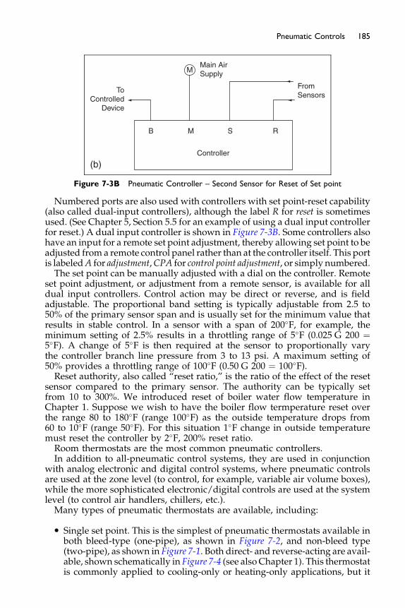
ToControlled
Device
FromSensors
Main AirSupply
B M S
Controller
(b)
R
M
Figure 7-3B Pneumatic Controller – Second Sensor for Reset of Set point
185Pneumatic Controls
Numbered ports are also used with controllers with set point-reset capability(also called dual-input controllers), although the label R for reset is sometimesused. (See Chapter 5, Section 5.5 for an example of using a dual input controllerfor reset.) A dual input controller is shown in Figure 7-3B. Some controllers alsohave an input for a remote set point adjustment, thereby allowing set point to beadjusted from a remote control panel rather than at the controller itself. This portis labeledA for adjustment,CPA for control point adjustment, or simply numbered.The set point can be manually adjusted with a dial on the controller. Remote
set point adjustment, or adjustment from a remote sensor, is available for alldual input controllers. Control action may be direct or reverse, and is fieldadjustable. The proportional band setting is typically adjustable from 2.5 to50% of the primary sensor span and is usually set for the minimum value thatresults in stable control. In a sensor with a span of 200�F, for example, theminimum setting of 2.5% results in a throttling range of 5�F (0.025 G 200 ¼5�F). A change of 5�F is then required at the sensor to proportionally varythe controller branch line pressure from 3 to 13 psi. A maximum setting of50% provides a throttling range of 100�F (0.50 G 200 ¼ 100�F).Reset authority, also called “reset ratio,” is the ratio of the effect of the reset
sensor compared to the primary sensor. The authority can be typically setfrom 10 to 300%. We introduced reset of boiler water flow temperature inChapter 1. Suppose we wish to have the boiler flow termperature reset overthe range 80 to 180�F (range 100�F) as the outside temperature drops from60 to 10�F (range 50�F). For this situation 1�F change in outside temperaturemust reset the controller by 2�F, 200% reset ratio.Room thermostats are the most common pneumatic controllers.In addition to all-pneumatic control systems, they are used in conjunction
with analog electronic and digital control systems, where pneumatic controlsare used at the zone level (to control, for example, variable air volume boxes),while the more sophisticated electronic/digital controls are used at the systemlevel (to control air handlers, chillers, etc.).Many types of pneumatic thermostats are available, including:
� Single set point. This is the simplest of pneumatic thermostats available inboth bleed-type (one-pipe), as shown in Figure 7-2, and non-bleed type(two-pipe), as shown in Figure 7-1. Both direct- and reverse-acting are avail-able, shown schematically in Figure 7-4 (see also Chapter 1). This thermostatis commonly applied to cooling-only or heating-only applications, but it
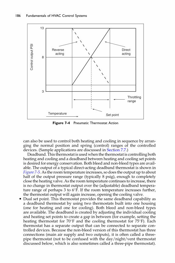
Con
trol
out
put P
SI
13
8
3
Temperature Set point
Throttlingrange
Direct acting
Reverseacting
Figure 7-4 Pneumatic Thermostat Action
186 Fundamentals of HVAC Control Systems
can also be used to control both heating and cooling in sequence by arran-ging the normal position and spring (control) ranges of the controlleddevices. (Sample applications are discussed in Section 7.7.)
Deadband. This thermostat is usedwhen the thermostat is controllingbothheating and cooling and a deadband between heating and cooling set pointsis desired for energy conservation. Both bleed and non-bleed types are avail-able. The output of a typical direct-acting deadband thermostat is shown inFigure 7-5. As the room temperature increases, so does the output up to abouthalf of the output pressure range (typically 8 psig), enough to completelyclose the heating valve. As the room temperature continues to increase, thereis no change in thermostat output over the (adjustable) deadband tempera-ture range of perhaps 3 to 6�F. If the room temperature increases further,the thermostat output will again increase, opening the cooling valve.
� Dual set point. This thermostat provides the same deadband capability asa deadband thermostat by using two thermostats built into one housing(one for heating and one for cooling). Both bleed and non-bleed typesare available. The deadband is created by adjusting the individual coolingand heating set points to create a gap in between (for example, setting theheating thermostat for 70�F and the cooling thermostat for 75�F). Eachthermostat has a separate output that can be connected to separate con-trolled devices. Because the non-bleed version of this thermostat has threeconnections (main air supply and two outputs), it is often called a three-pipe thermostat (not to be confused with the day/night/vent thermostatdiscussed below, which is also sometimes called a three-pipe thermostat).
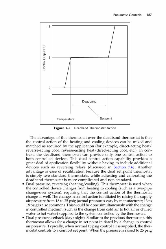
13
8
3
Temperature Set point
Deadband
Con
trol
Out
put P
Sl
Figure 7-5 Deadband Thermostat Action
187Pneumatic Controls
The advantage of this thermostat over the deadband thermostat is thatthe control action of the heating and cooling devices can be mixed andmatched as required by the application (for example, direct-acting heat/reverse-acting cool, reverse-acting heat/direct-acting cool, etc.). In con-trast, the deadband thermostat can provide only one control action toboth controlled devices. This dual control action capability provides agreat deal of application flexibility without having to include additionaldevices such as reversing relays (discussed in Section 7.6). Anotheradvantage is ease of recalibration because the dual set point thermostatis simply two standard thermostats, while adjusting and calibrating thedeadband thermostat is more complicated and non-standard.
� Dual pressure, reversing (heating/cooling). This thermostat is used whenthe controlled device changes from heating to cooling (such as a two-pipechange-over system), requiring that the control action of the thermostatchange aswell. The change in control action is initiated by raising the supplyair pressure from 18 to 25 psig (actual pressures vary by manufacturer; 13 to18psig is also common). Thiswould bedone simultaneouslywith the changein controlled medium (such as the change from cold air to hot air or chilledwater to hot water) supplied to the system controlled by the thermostat.
� Dual pressure, setback (day/night). Similar to the previous thermostat, thisthermostat allows for a change in set point initiated by a change in controlair pressure. Typically, when normal 18 psig control air is supplied, the ther-mostat controls to a comfort set point. When the pressure is raised to 25 psig
188 Fundamentals of HVAC Control Systems
at night, the thermostat switches over internally to control to a set point that islower (for heating systems), or higher (for cooling systems) to reduce energyusage when the space is unoccupied. (A more common means of achievingsetback/setup on air systems is to simply shut the HVAC system off at nightanduse a separate night setback and/or setup thermostat to start andoperatethe system temporarily as required to prevent overly cold or hot space tem-peratures.) A variation on this thermostat is the day/night/vent thermostat,which has a secondoutput in addition to the thermostat signal. This output isswitched on (set equal to themain air pressure) when the thermostat is in thedaymode, and switched off (the signal is bledoff) at night. This auxiliary out-put was intended to open a ventilation outdoor air damper (hence the name,day/night/vent), but it can be used to initiate any day-only or night-onlyfunction.
Thermostats are available with blank locking covers; this is the most com-mon arrangement because it discourages tampering by unauthorized users.Accessible set point adjustment and face mounted temperature indicatorsare also available.
Did you notice the words “blank locking covers; this is the most commonarrangement because it discourages tampering by unauthorized users.”We control temperature in the vast majority of situations for comfort.The ASHRAE Standard 55 on thermal comfort shows a temperatureband of about 7�F for 80% of the occupants to be thermally comfortableassuming similar clothing.
So rather than allow adjustment to get as many people as possiblecomfortable we fix the temperature. Is it any wonder that people are notimpressed with the engineering for comfort in many of our buildings?
Pneumatic thermostats and other pneumatic receiver/controllers requirefrequent recalibration to maintain accuracy. At least semi-annual (six-month)recalibration is recommended. Transmitters, such as temperature and pres-sure transmitters, should be recalibrated annually.
Despite this need for frequent recalibration, pneumatic controls are verydurable and reliable. Almost all components (controllers, transmitters, relays,etc.) are interchangeable among manufactures. These advantages are oftenoverlooked when control system type is selected.
7.4 Actuators
The pneumatic actuator (also called an operator or motor) is arguably the sim-plest and most reliable device used in HVAC control systems. As shown inFigure 7-6, it consists of a metal cylinder, a piston, a flexible diaphragm, and
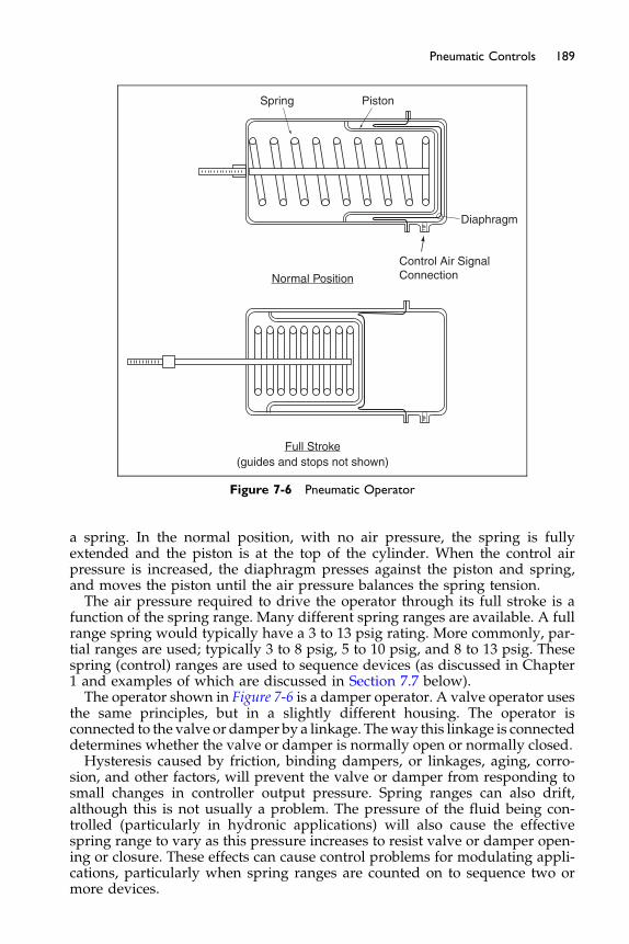
Spring
Diaphragm
Control Air SignalConnectionNormal Position
Full Stroke(guides and stops not shown)
Piston
Figure 7-6 Pneumatic Operator
189Pneumatic Controls
a spring. In the normal position, with no air pressure, the spring is fullyextended and the piston is at the top of the cylinder. When the control airpressure is increased, the diaphragm presses against the piston and spring,and moves the piston until the air pressure balances the spring tension.The air pressure required to drive the operator through its full stroke is a
function of the spring range. Many different spring ranges are available. A fullrange spring would typically have a 3 to 13 psig rating. More commonly, par-tial ranges are used; typically 3 to 8 psig, 5 to 10 psig, and 8 to 13 psig. Thesespring (control) ranges are used to sequence devices (as discussed in Chapter1 and examples of which are discussed in Section 7.7 below).The operator shown in Figure 7-6 is a damper operator. A valve operator uses
the same principles, but in a slightly different housing. The operator isconnected to the valve or damper by a linkage. Theway this linkage is connecteddetermines whether the valve or damper is normally open or normally closed.Hysteresis caused by friction, binding dampers, or linkages, aging, corro-
sion, and other factors, will prevent the valve or damper from responding tosmall changes in controller output pressure. Spring ranges can also drift,although this is not usually a problem. The pressure of the fluid being con-trolled (particularly in hydronic applications) will also cause the effectivespring range to vary as this pressure increases to resist valve or damper open-ing or closure. These effects can cause control problems for modulating appli-cations, particularly when spring ranges are counted on to sequence two ormore devices.
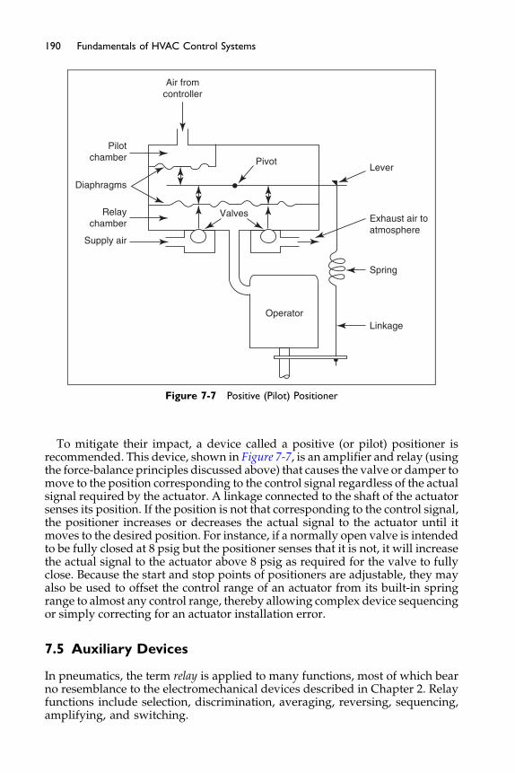
Air fromcontroller
Pilotchamber
Diaphragms
Relaychamber
Supply air
Lever
Exhaust air toatmosphere
Spring
Linkage
Pivot
Operator
Valves
Figure 7-7 Positive (Pilot) Positioner
190 Fundamentals of HVAC Control Systems
To mitigate their impact, a device called a positive (or pilot) positioner isrecommended. This device, shown in Figure 7-7, is an amplifier and relay (usingthe force-balance principles discussed above) that causes the valve or damper tomove to the position corresponding to the control signal regardless of the actualsignal required by the actuator. A linkage connected to the shaft of the actuatorsenses its position. If the position is not that corresponding to the control signal,the positioner increases or decreases the actual signal to the actuator until itmoves to the desired position. For instance, if a normally open valve is intendedto be fully closed at 8 psig but the positioner senses that it is not, it will increasethe actual signal to the actuator above 8 psig as required for the valve to fullyclose. Because the start and stop points of positioners are adjustable, they mayalso be used to offset the control range of an actuator from its built-in springrange to almost any control range, thereby allowing complex device sequencingor simply correcting for an actuator installation error.
7.5 Auxiliary Devices
In pneumatics, the term relay is applied to many functions, most of which bearno resemblance to the electromechanical devices described in Chapter 2. Relayfunctions include selection, discrimination, averaging, reversing, sequencing,amplifying, and switching.
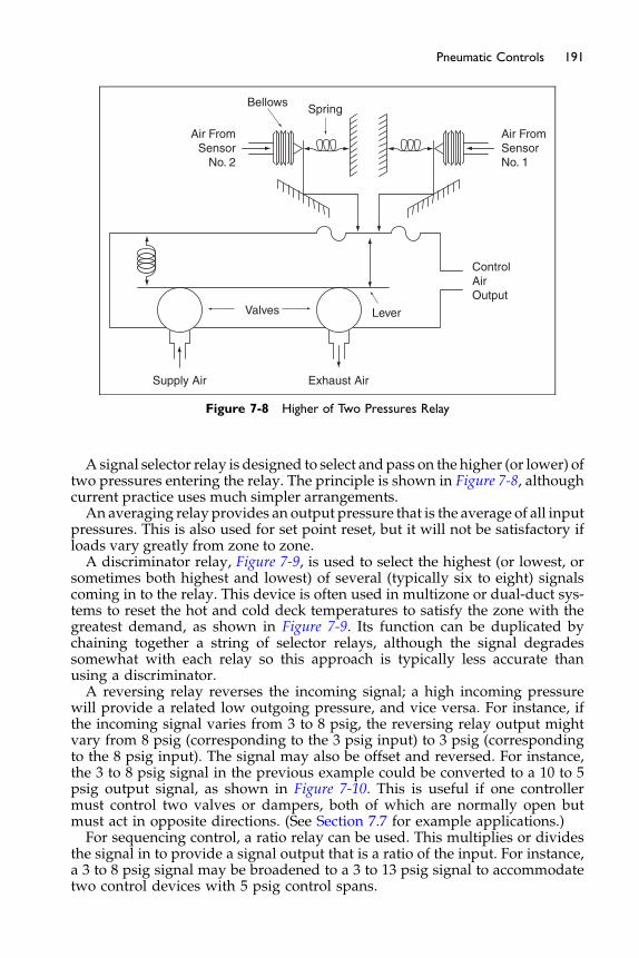
Supply Air Exhaust Air
Valves Lever
ControlAirOutput
Air FromSensorNo. 1
BellowsSpring
Air FromSensor
No. 2
Figure 7-8 Higher of Two Pressures Relay
191Pneumatic Controls
Asignal selector relay is designed to select andpass on the higher (or lower) oftwo pressures entering the relay. The principle is shown in Figure 7-8, althoughcurrent practice uses much simpler arrangements.An averaging relay provides an output pressure that is the average of all input
pressures. This is also used for set point reset, but it will not be satisfactory ifloads vary greatly from zone to zone.A discriminator relay, Figure 7-9, is used to select the highest (or lowest, or
sometimes both highest and lowest) of several (typically six to eight) signalscoming in to the relay. This device is often used in multizone or dual-duct sys-tems to reset the hot and cold deck temperatures to satisfy the zone with thegreatest demand, as shown in Figure 7-9. Its function can be duplicated bychaining together a string of selector relays, although the signal degradessomewhat with each relay so this approach is typically less accurate thanusing a discriminator.A reversing relay reverses the incoming signal; a high incoming pressure
will provide a related low outgoing pressure, and vice versa. For instance, ifthe incoming signal varies from 3 to 8 psig, the reversing relay output mightvary from 8 psig (corresponding to the 3 psig input) to 3 psig (correspondingto the 8 psig input). The signal may also be offset and reversed. For instance,the 3 to 8 psig signal in the previous example could be converted to a 10 to 5psig output signal, as shown in Figure 7-10. This is useful if one controllermust control two valves or dampers, both of which are normally open butmust act in opposite directions. (See Section 7.7 for example applications.)For sequencing control, a ratio relay can be used. This multiplies or divides
the signal in to provide a signal output that is a ratio of the input. For instance,a 3 to 8 psig signal may be broadened to a 3 to 13 psig signal to accommodatetwo control devices with 5 psig control spans.
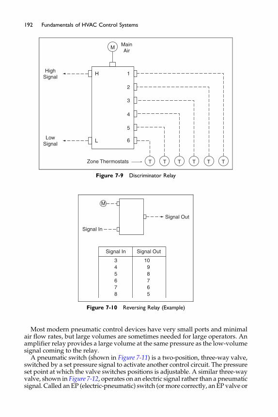
HighSignal
H 1
MainAir
2
3
4
5
6
T T T T T TZone Thermostats
LLowSignal
M
Figure 7-9 Discriminator Relay
Signal In
M
Signal In
345678
1098765
Signal Out
Signal Out
Figure 7-10 Reversing Relay (Example)
192 Fundamentals of HVAC Control Systems
Most modern pneumatic control devices have very small ports and minimalair flow rates, but large volumes are sometimes needed for large operators. Anamplifier relay provides a large volume at the same pressure as the low-volumesignal coming to the relay.
A pneumatic switch (shown in Figure 7-11) is a two-position, three-way valve,switched by a set pressure signal to activate another control circuit. The pressureset point at which the valve switches positions is adjustable. A similar three-wayvalve, shown in Figure 7-12, operates on an electric signal rather than a pneumaticsignal. Called anEP (electric-pneumatic) switch (ormore correctly, an EP valve or
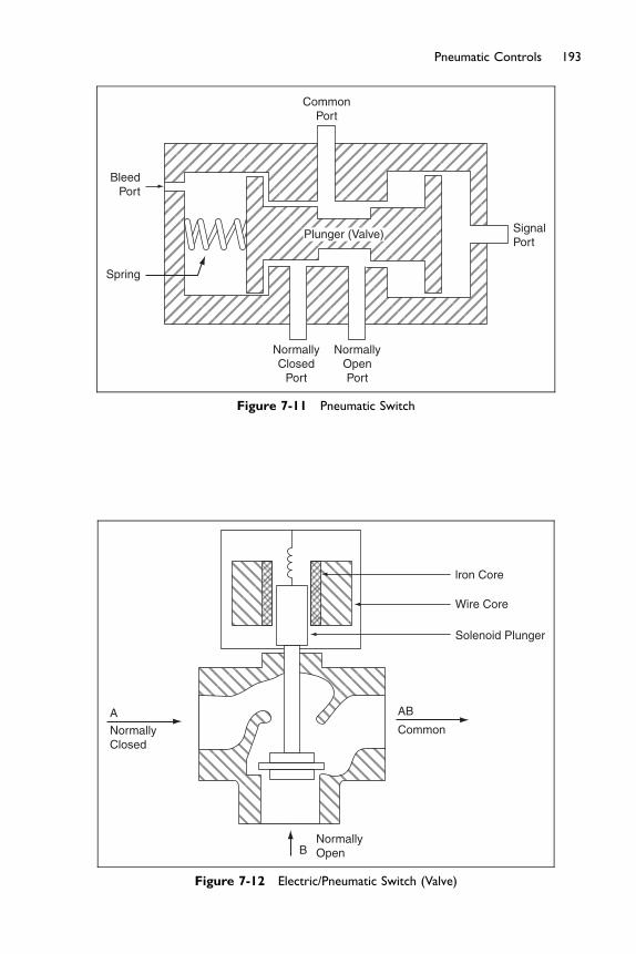
BleedPort
CommonPort
SignalPort
NormallyClosed
Port
NormallyOpenPort
Spring
Plunger (Valve)
Figure 7-11 Pneumatic Switch
A
B
NormallyClosed
NormallyOpen
AB
lron Core
Wire Core
Solenoid Plunger
Common
Figure 7-12 Electric/Pneumatic Switch (Valve)
193Pneumatic Controls

194 Fundamentals of HVAC Control Systems
solenoid air valve), it changes the position of the valve when the electromagneticcoil is energized by an electric circuit, typically 24 VAC/DC or 120 V.
It is important to note that pneumatic valves always are three-way valveseven when the logical duty of the valve is two-position. This is because apneumatic signal (pressure) will remain until it is bled off, unlike an electriccircuit for which the electric signal is lost when a switch is opened. This con-cept can be better understood by the example shown in Figure 7-13. A damperis to be opened when a fan is turned on, as indicated by its starter auxiliarycontact. When the contact closes, the common port of the EP switch isconnected to the normally closed port, allowing main air to flow to the actua-tor, opening the damper. When the contact is opened when the fan shuts off,the EP switch is de-energized and the main air connection is shut off from thedamper. But if only a two-way valve was used, the damper would remainopen because the pressure in the line to the actuator would remain. This pres-sure must be bled off for the damper to close. Hence, a three-way valve isrequired with the normally open port (the port that is connected to the com-mon port when the EP switch is de-energized) open to atmosphere. This isindicated as an arrow, as shown in Figure 7-13.
The connection of the three-way valve is important. Typically, the con-trolled device is connected to the common port. One port, either the normallyopen (NO) or normally closed (NC) depending on the wiring and pipingarrangement, is typically connected to the output from a controller. The thirdport is usually either open to atmosphere or connected to main air to cause thevalve or damper to fully open or close when the EP switch is energized (NCport) or de-energized (NO port).
Note that the terms NC and NO mean essentially the opposite of theirmeaning with electrical circuits. A port that is open to another allows controlair to pass, while an open electrical contact does not allow current to pass.This can be confusing.
Another very common relay is the PE (pneumatic-electric) switch shown inFigure 7-14. It is simply a pressure actuated relay, usually with an adjustableset point, that will open or close an electrical contact. A typical applicationis to create step-control logic from a pneumatic controller (see Chapter 1).The PE is used commonly to interlock electrical equipment.
ControlPower
EP Switch
MainAir
MNC
NOC
OpenPort
DM
DamperMotor
N.C. Damper
Fan StarterAux Contact
Figure 7-13 Electric/Pneumatic Switch Application
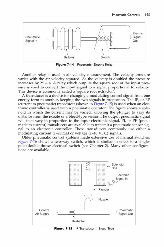
Bellows Switch
ElectricSignalOut
PneumaticSignal In
Figure 7-14 Pneumatic- Electric Relay
195Pneumatic Controls
Another relay is used in air velocity measurement. The velocity pressurevaries with the air velocity squared. As the velocity is doubled the pressureincreases by 22 ¼ 4. A relay which outputs the square root of the input pres-sure is used to convert the input signal to a signal proportional to velocity.This device is commonly called a ‘square root extractor’.A transducer is a device for changing a modulating control signal from one
energy form to another, keeping the two signals in proportion. The IP, or EP(current to pneumatic) transducer (shown in Figure 7-15) is used when an elec-tronic controller is used with a pneumatic operator. The figure shows a sole-noid in which the current may be varied, allowing the plunger to vary itsdistance from the nozzle of a bleed-type sensor. The output pneumatic signalwill then vary in proportion to the input electronic signal. PI, or PE (pneu-matic to current) transducers are available to transmit a pneumatic sensor sig-nal to an electronic controller. These transducers commonly use either amodulating current (1–20 ma) or voltage (1–10 VDC) signals.Older pneumatic control systems made extensive use of manual switches.
Figure 7-16 shows a two-way switch, which is similar in effect to a single-pole/double-throw electrical switch (see Chapter 2). Many other configura-tions are available.
ControlAir Supply
PneumaticSignal Out
Restrictor
Nozzle
Plunger
SolenoidCoil
ElectronicSignal In
Figure 7-15 IP Transducer – Bleed Type
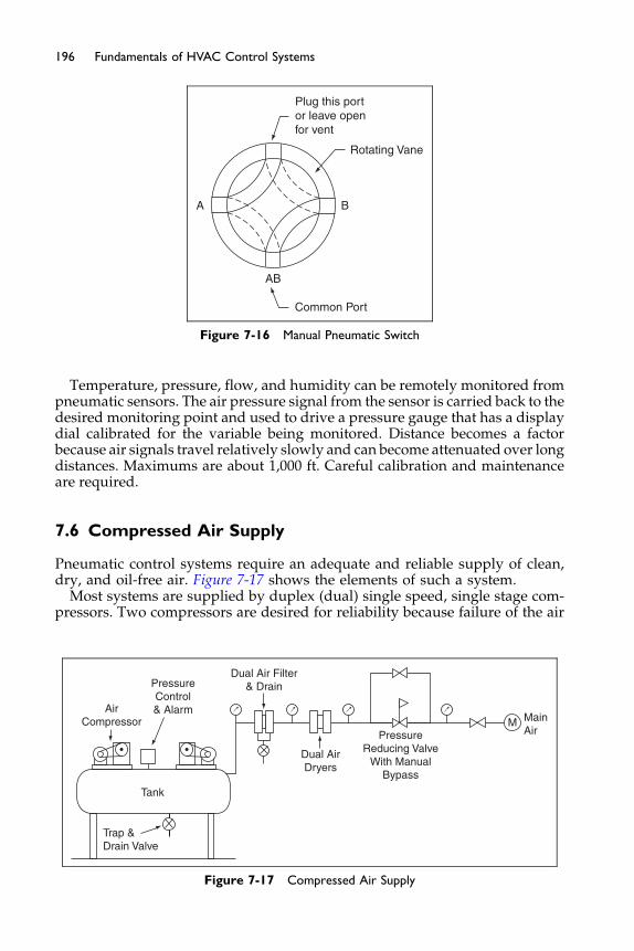
A B
AB
Common Port
Plug this portor leave openfor vent
Rotating Vane
Figure 7-16 Manual Pneumatic Switch
196 Fundamentals of HVAC Control Systems
Temperature, pressure, flow, and humidity can be remotely monitored frompneumatic sensors. The air pressure signal from the sensor is carried back to thedesired monitoring point and used to drive a pressure gauge that has a displaydial calibrated for the variable being monitored. Distance becomes a factorbecause air signals travel relatively slowly and can become attenuated over longdistances. Maximums are about 1,000 ft. Careful calibration and maintenanceare required.
7.6 Compressed Air Supply
Pneumatic control systems require an adequate and reliable supply of clean,dry, and oil-free air. Figure 7-17 shows the elements of such a system.
Most systems are supplied by duplex (dual) single speed, single stage com-pressors. Two compressors are desired for reliability because failure of the air
AirCompressor
PressureControl& Alarm
Dual Air Filter& Drain
Tank
Dual AirDryers
PressureReducing Valve
With ManualBypass
MainAir
M
Trap &Drain Valve
Figure 7-17 Compressed Air Supply
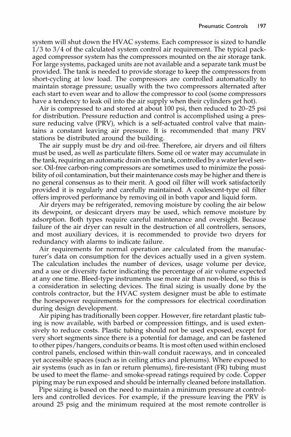
197Pneumatic Controls
system will shut down the HVAC systems. Each compressor is sized to handle1/3 to 3/4 of the calculated system control air requirement. The typical pack-aged compressor system has the compressors mounted on the air storage tank.For large systems, packaged units are not available and a separate tank must beprovided. The tank is needed to provide storage to keep the compressors fromshort-cycling at low load. The compressors are controlled automatically tomaintain storage pressure; usually with the two compressors alternated aftereach start to even wear and to allow the compressor to cool (some compressorshave a tendency to leak oil into the air supply when their cylinders get hot).Air is compressed to and stored at about 100 psi, then reduced to 20–25 psi
for distribution. Pressure reduction and control is accomplished using a pres-sure reducing valve (PRV), which is a self-actuated control valve that main-tains a constant leaving air pressure. It is recommended that many PRVstations be distributed around the building.The air supply must be dry and oil-free. Therefore, air dryers and oil filters
must be used, as well as particulate filters. Some oil or water may accumulate inthe tank, requiring an automatic drain on the tank, controlled by awater level sen-sor. Oil-free carbon-ring compressors are sometimes used to minimize the possi-bility of oil contamination, but theirmaintenance costsmay be higher and there isno general consensus as to their merit. A good oil filter will work satisfactorilyprovided it is regularly and carefully maintained. A coalescent-type oil filteroffers improved performance by removing oil in both vapor and liquid form.Air dryers may be refrigerated, removing moisture by cooling the air below
its dewpoint, or desiccant dryers may be used, which remove moisture byadsorption. Both types require careful maintenance and oversight. Becausefailure of the air dryer can result in the destruction of all controllers, sensors,and most auxiliary devices, it is recommended to provide two dryers forredundancy with alarms to indicate failure.Air requirements for normal operation are calculated from the manufac-
turer’s data on consumption for the devices actually used in a given system.The calculation includes the number of devices, usage volume per device,and a use or diversity factor indicating the percentage of air volume expectedat any one time. Bleed-type instruments use more air than non-bleed, so this isa consideration in selecting devices. The final sizing is usually done by thecontrols contractor, but the HVAC system designer must be able to estimatethe horsepower requirements for the compressors for electrical coordinationduring design development.Air piping has traditionally been copper. However, fire retardant plastic tub-
ing is now available, with barbed or compression fittings, and is used exten-sively to reduce costs. Plastic tubing should not be used exposed, except forvery short segments since there is a potential for damage, and can be fastenedto other pipes/hangers, conduits or beams. It ismost often usedwithin enclosedcontrol panels, enclosed within thin-wall conduit raceways, and in concealedyet accessible spaces (such as in ceiling attics and plenums). Where exposed toair systems (such as in fan or return plenums), fire-resistant (FR) tubing mustbe used to meet the flame- and smoke-spread ratings required by code. Copperpipingmay be run exposed and should be internally cleaned before installation.Pipe sizing is based on the need to maintain a minimum pressure at control-
lers and controlled devices. For example, if the pressure leaving the PRV isaround 25 psig and the minimum required at the most remote controller is

198 Fundamentals of HVAC Control Systems
18 psig, then piping must be sized for a pressure drop less than 7 psi. Thisrather high range is typical and it leads to fairly small pipe sizes in most appli-cations. Main air lines are typically 1/2 to 3/8 inch. Branch line tubing sizes of1/4 inch and 1/8 (5/32) inch are most commonly used. Friction tables andcharts are available from controls and air compressor manufacturers for sizingpipe for larger systems. To reduce pipe sizes in very large systems, distribu-tion mains may be high pressure (50 to 100 psi) with pressure reducing valves(PRVs) as required to serve small areas of the facility (for example, one or twostoreys of a high-rise building). Make sure the pneumatic main air lines andPRV locations are accessible and clearly identified.
As shown in Figure 7-17 and other figures, main supply air connections aretypically shown in diagrams as an M with a circle around it. This indicates asupply of air from the control air system. If the air is taken ahead of the pres-sure reducing assembly, it is often labeled as HP for high pressure. Fre-quently, control air is switched on and off for control purposes (such as toshut normally closed devices at night). In this case, the control air supply islabeled as S to indicate switched main air.
7.7 Example Applications
Figure 7-18 shows the symbols commonly used in pneumatic diagrams,although symbols can vary among designers and manufacturers. Because ofthis variation, each designer must provide a legend defining the symbols usedin his or her diagrams. Unless the designer wants to use a particular controlvendor, it is preferable to use generic symbols and indicate connectionsbetween devices by dashed lines. This allows the contractor maximum lati-tude in adapting a particular manufacturer’s devices to the systems. Note thatthe following two figures, 1-19 and 1-20, do not conform entirely with thesymbols here but the alternative symbols and explanatory notes make it clearwhat each item is on the drawing.
Figure 7-19 shows a single zone unit with hydronic heating and cooling coils,similar to the example introduced in Chapter 5 and developed in Chapter 6withelectric controls. As before, the control sequence for this system reads:
� Start/stop. The system shall start and stop based on the time schedule seton the seven-day timeclock. The fan shall stop if the freeze-stat indicatesfreezing temperatures or the duct smoke detector detects smoke.
� Heating/cooling control. Heating and cooling shall be controlled to main-tain room temperature at set point (70 to 75�F, adjustable) by a single setpoint proportional room thermostat modulating two-way control valves.
� Outdoor air damper. The outdoor air damper shall open whenever thefan is energized and close when the fan is off.
The system includes a small temperature control panel to house an electrictimeclock and EP valve. The panel could be located in a mechanical room forconvenient but restricted access (to keep people from tampering with thetimeclock, for instance).
The 120 V fan motor is started by running power wiring directly throughthe timeclock, smoke detector and freeze-stat contacts. These contacts must

Main Control Air SupplyM AR
DM
NC
NO
C
EP
PE
EP
TT
T
HT
H
R
RR
F
R
NC
NO
C
Control Air Supply From EP
PE Relay
EP Relay
Temperature Transmitter*
Room Thermostat
Humidity Transmitter*
Room Humidistat
Pressure Sensor
Pressure Gauge
Differential Pressure Sensor
Relay (add description)
Reversing Relay
Flow Sensor
Discriminator
Gradual Switch
Averaging Relay
Damper Motor
Opposed Blade Damper
Parallel Blade Damper
Inlet Vane Damper
Fluid Control Valve − 3-way
Fluid Control Valve − 2-way
Low TemperatureSafety Switch
Manual Switch (pneumatic)
LLT
SD
F
I/P
P/I
R/C
R/C
B M S
B M S
R
Smoke Detector (duct)
Fire Stat (duct)
Duct or Pipe Thermometerwith Well
Current/PneumaticTransducer
Pneumatic/CurrentTransducer
Receiver/Controller(with reset port)
Receiver/Controller(may also be labelled “C”without other labels)
P
DP
Figure 7-18 Symbols for Pneumatic Logic Diagrams
199Pneumatic Controls
be rated for the motor current. This circuit also energizes the EP valve thatprovides main air to the outdoor air damper actuator, opening the normallyclosed damper. In this case, the EP coil must be rated for 120 V. Note thatpower to the EP valve is taken after the smoke detector and freeze-stat so thatthe damper will shut if either of these safeties trip. For slightly more foolproofperformance, the EP valve could also have been powered in parallel with the

HWR
3-8 #N.O.
8-13 #N.C.
CHWRSmoke Detector
SupplyFanRETURN
AIR
N.C. HWS CHWS
Freezestat
120 V Panel
TC
TimeClock EP N.C.
N.O.M
MainAirC
Relay
120 V Powerto Motor
MainAir
MT
2-PipeT’stat
MinimumOutside Air
Figure 7-19 Single Zone Pneumatic/Electric Control
200 Fundamentals of HVAC Control Systems
fan motor from the load side of the starter. This would cause the EP valve toclose the outdoor air damper if the starter drops out due to a motor overload(in addition to the other safety interlocks, such as smoke dampers).
The thermostat is a single set point thermostat controlling both the heatingand cooling valves. For these valves to sequence properly, the control actionand spring ranges must be properly selected. In this example, the heating valvewas selected to be normally open so that even if the control air system failed,heat could be supplied to the space. This is a common fail-safe selection. Thenormally open heating valve requires that the thermostat be direct-acting so thata drop in space temperature will result in a drop in controller output signal,opening the hot water valve.
The standard spring range for a normally open valve is 3 to 8 psig. (Somemanufacturers use 2 to 7 psig or 2 to 5 psig.) If the controller is to be used todirectly control cooling as well, the cooling valve must be normally closed andoperate from 8 to 13 psig. Again, this is the standard spring range available withnormally closed valves.
As with the example discussed in Chapter 6, this design is missing somefrequently desired control features such as night setback operating with the
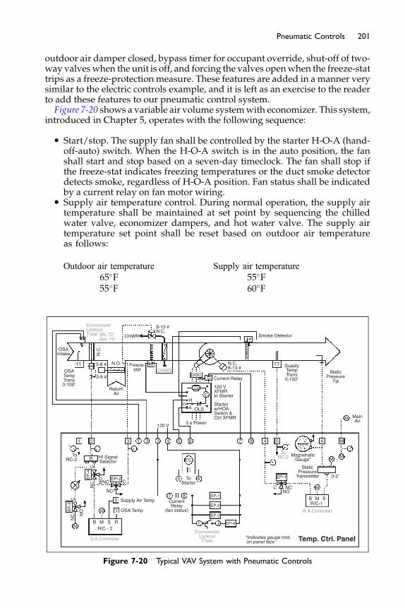
201Pneumatic Controls
outdoor air damper closed, bypass timer for occupant override, shut-off of two-way valveswhen the unit is off, and forcing the valves openwhen the freeze-stattrips as a freeze-protection measure. These features are added in a manner verysimilar to the electric controls example, and it is left as an exercise to the readerto add these features to our pneumatic control system.Figure 7-20 shows a variable air volume systemwith economizer. This system,
introduced in Chapter 5, operates with the following sequence:
� Start/stop. The supply fan shall be controlled by the starter H-O-A (hand-off-auto) switch. When the H-O-A switch is in the auto position, the fanshall start and stop based on a seven-day timeclock. The fan shall stop ifthe freeze-stat indicates freezing temperatures or the duct smoke detectordetects smoke, regardless of H-O-A position. Fan status shall be indicatedby a current relay on fan motor wiring.
� Supply air temperature control. During normal operation, the supply airtemperature shall be maintained at set point by sequencing the chilledwater valve, economizer dampers, and hot water valve. The supply airtemperature set point shall be reset based on outdoor air temperatureas follows:
Outdoor air temperature Supply air temperature65�F 55�F55�F 60�F
Temp. Ctrl. PanelD.A.Controller
EconomizerLockoutT’stat
Supply Air Temp
OSA Temp1
5
M
M
NC
NC
EP
-4
EP-2
HI SignalSelector
EP
-3N
CC
NO
NO
C
C
R
1 2 3 1 2 3 4
120 V
OSATempTrans0-100�
OSAIntake
EconomizerLockoutT’stat Mk: 72�
TT
N.C
.
N.O.
ReturnAir
3-8 #
3-8 #
Freeze-stat
8-13 #N.C.
CHWR
CHWS
N.C.8-13 #
Current Relay
Smoke Detector
SupplyTempTrans0-100�
StaticPressure
Tip
TT
Brk: 75�
OLSA
C
DISC
120 VXFMRIn Starter
Starterw/HOASwitch &Ctrl XFMR
OH
3 φ Power
5 6 7 8 4 5 6 M
MM
MNC
EP-1
NOC
R/C-1
R.A.Controller
*Indicates gauge mtd. on panel face
B M S
0-2’
ToRC-2 Magnehelic
Gauge*
StaticPressure
Transmitter
M MainAir
TC
5
7 8 EP-1
EP-2
EP-3
1 2 EP-4
CurrentRelay
(fan status)
6ToStarter
ToRC-2
* *
NO
R/C - 2B M S R
Figure 7-20 Typical VAV System with Pneumatic Controls
202 Fundamentals of HVAC Control Systems
Both valves and the outdoor air damper shall be closed when the fan isoff.
� Economizer. Economizer control shall be disabled when the outdoor airtemperature is greater than the outdoor air high limit thermostat set point(67�F with a 3�F differential). The signal to the outdoor air damper shallbe the larger of the signal from the supply air controller and the signalcorresponding to minimum outdoor air intake required for ventilation (tobe established by the balancing contractor in the field). (Note: this type ofminimum ventilation control, while common, will not maintain a constantminimum amount of outdoor air andmay notmeet ventilation codes.Moreadvanced ventilation outdoor air control designs are beyond the scope ofthis course.)
� Static pressure control. Whenever the fan is commanded on, duct staticpressure shall be maintained at set point by modulating inlet guide vanesusing PI logic. The static pressure set point shall be determined by the airbalancer as that required to satisfy all VAV boxes when the fan system isoperating at design air flow. Inlet vanes shall be closed when the fan is off.
The H-O-A switch is wired so that the normally closed contacts of thesmoke detector and freeze-stat are wired before the hand (H) position so thatthe fan will not start if either safety contact is open. The auto (A) position iswired from the H contact through the timeclock contact to start the fan whenthe switch is in the auto position. The fan will then start either when the H-O-Aswitch is in the hand position, or when the switch is in the auto position and thetimeclock contact is closed, provided the safeties are satisfied.
The normal positions of inlet guide vanes, chilled water valve, any ductsmoke dampers, and outdoor air damper were all selected to be normallyclosed so that they will close automatically when the fan is off, as desiredby the control sequence. This is done by bleeding the control signal from theline serving each of these devices using EP valves. When the fan stops, thecurrent relay on one of the power lines to the fan motor will de-energizeand its contact will open. As can be seen from the ladder diagram, this willde-energize EP valves EP-1, 2, 3, and 4, connecting their common port (whichis piped to the controlled device) to the NO port, which is vented to atmo-sphere. This bleeds the signal, and the inlet vanes, chilled water valve, andoutdoor air damper all close. Conversely, when the fan is on, the current relaycontact closes which energizes the EP valves, thereby allowing the controllersignal to modulate the controlled devices.
Note that control air supply is maintained to the two controllers in thepanel. Two of the four EP valves in the panel could have been eliminated ifwe simply switched the main control air supplied to the controllers on andoff with the supply fan. This would cause the control air to bleed out of thecontrollers when the fan shut off, and hence bleed the control signal lines tothe normally closed valves, dampers, and inlet vanes. However, this wasnot done for two reasons:
� With many pneumatic controllers, it is an important design rule to main-tain a constant control air supply because they tend to drift and requiremore frequent recalibration when supply air is intermittent. While some

203Pneumatic Controls
modern thermostats and controllers are generally resistant to this calibra-tion drift, it is good practice nevertheless to maintain constant main airwhenever possible.
� Bleeding air from the control valve and damper signals through thereceiver/controller takes more time, and may not completely bleed thepressure depending on the specific design of the receiver controller.Any residual pressure may keep the valve or damper from fully closing.
While this design rule is recommended, it is commonly broken in practicewithout causing significant problems. A very common example is the use ofa switched main air supply to zone thermostats. This might be done to effecta control sequence (such as to open up normally open VAV boxes for morningwarm-up) or simply to save air compressor energy at night by eliminating theconstant bleeding of air from the thermostats. If this is done, it is importantthat the thermostats specified be resistant to the calibration drift associatedwith intermittent main air supply.The supply fan inlet guide vanes are controlled by sensing duct static pres-
sure using a static pressure tip, which is simply a fitting that sticks out into theduct with a pickup designed to help ensure that static pressure in the duct ismeasured, rather than total or velocity pressure. This signal, which typically isin the range of 0 to 2 inch wg, must be amplified so that it can be used by apneumatic controller. This is done using a static pressure transmitter.Transmitters are available in various input signal ranges and it is important to
pick a range that is as close as possible to the expected conditions so that thepneumatic signal is accurate and a large change in signal results from a normalchange in static pressure. The transmitter output is fed into a reverse-actingreceiver controller (RC-1) whose output is then piped to the normally closedinlet vanes. The controller is reverse-acting because upon a rise in duct pressure,we want the inlet vanes to close. Because the vanes are normally closed, theywill close upon a drop in signal. This is in the opposite direction as the changein duct pressure, so the controller must be reverse-acting.Supply air temperature is controlled by piping the signal from a supply air
temperature transmitter to a direct-acting receiver controller (RC-2). The con-troller has a reset port that is connected to an outdoor air temperature trans-mitter. The controller is then adjusted to provide the desired reset scheduleshown. This type of reset is common to reduce reheat losses in cold weatherand to increase overall supply air rates for improved ventilation.The output fromRC-2 is piped to the chilledwater valve and economizer dam-
pers, which are arranged to operate in sequence. The outdoor air damper opensfirst when the controller signal is in the range 3 to 8 psig, then the chilled watervalve openswhen the signal rises to the range of 8 to 13 psig. Note that the springrange and normal position selections are important for proper operation.The economizer damper signal passes first through an EP switch (EP-4) and
a signal selector relay. The EP switch is energized whenever the fan is on andthe outdoor air temperature is below 67�F, as indicated by an electric thermo-stat mounted in the outdoor air intake. The EP switch is piped so that the sig-nal from the controller passes through the EP switch to the signal selectorwhen the EP switch is energized. When the outdoor air temperature risesabove 70�F (67�F plus the 3�F differential), the EP switch is de-energized,
204 Fundamentals of HVAC Control Systems
bleeding air from the signal to the signal selector relay. The signal selector isused to maintain a minimum position signal to the dampers whenever thefan is on. A gradual switch (analogous to a potentiometer in an electric controlsystem) is adjusted as required to send the minimum position signal to thedampers as determined by the air balancer. The signal selector will then sendthe higher of the controller signal and the minimum position signal to thedampers.
Note that the pneumatic outdoor air temperature signal is not used to con-trol the economizer enable/disable lockout. Theoretically, this signal could besent to a pneumatic switching relay (see Figure 7-11). Instead, a separate elec-tric outdoor air thermostat is used along with an EP valve. The reason is thatthe resolution of the outdoor air temperature signal is not likely to be fineenough to provide the 3�F differential desired (75�F less 72�F). For instance,the transmitter might have a range of 0 to 100�F, with 0�F corresponding to3 psig and 100�F corresponding to 15 psig. This corresponds to 0.12 psig per �F(12 psig divided by 100�F). To achieve a 3�F differential, the switching relaymusthave a differential of 0.36 psig. Controllers with such a small differential are notgenerally available. Hence, the electric thermostat is used.
Pressure gauges are provided in key input and output lines in the panel tohelp in troubleshooting and as active displays of control points. Those gaugesthat are to be mounted on the panel face (such as outdoor air and supply airtemperature and duct static pressure) are marked with an asterisk in thediagram.
As with the previous example, many optional controls could have beenincluded to increase flexibility, but at higher cost and increased complication.
The Next Step
In the next chapter, we will learn about analog electronic controls. They arecommonly used for systems that are small yet complicated; too complicatedfor electric controls and too small to justify the high overhead cost of pneu-matic controls and some digital controls. Examples include packaged variableair volume unit controls. Like pneumatic controls, the falling cost of digitalcontrols is reducing the usage of analog electronic controls. Nevertheless,understanding analog electronic controls is important because they are stillused in existing buildings.
Bibliography
Honeywell Controls (2001) ACS Contractor CD-Rom. Minneapolis, MN.
Chapter 8
Analog Electronic Controls
Contents of Chapter 8
Study Objectives of Chapter 88.1 Principles of Operation
8.2 Sensors 8.3 Controllers 8.4 Actuators 8.5 Auxiliary Devices 8.6 Example Applications The Next StepBibliographyStudy Objectives of Chapter 8
Modern electronic controls use analog semiconductor components to effectcontrol logic. Several electronic controllers are commonly packaged into a sin-gle device that can handle all of the functions of a specific application such ascontrol of a single zone air handler. Like pneumatic controls, electronic con-trols are being replaced by direct digital controls. In the pre-digital controlera, electronic controls were most commonly used in packaged unitary equip-ment. However, they were never as popular as pneumatic controls for largecommercial projects due to their higher cost, and lack of standardization.After studying this chapter, you should be able to:
Understand the function of operational amplifiers (op-amps) in electroniccontrols.
Become familiar with some of the application-specific electronic controllersavailable.
Know how to use electronic controls in common HVAC applications.
8.1 Principles of Operation
Modern analog electronic controls are based on semiconductor solid-statetechnology. They differ from electric controls, which are based on changesin resistance and voltage, using conventional resistors, bridge circuits and
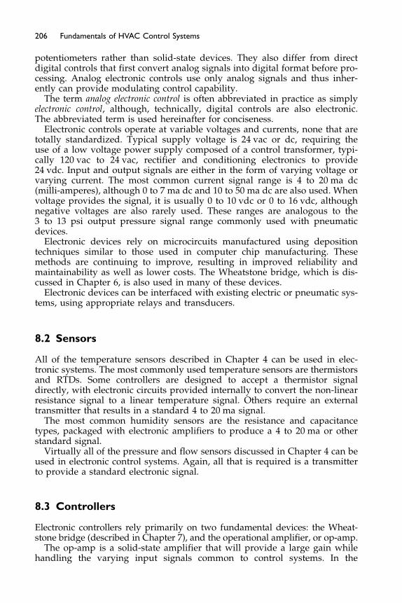
206 Fundamentals of HVAC Control Systems
potentiometers rather than solid-state devices. They also differ from directdigital controls that first convert analog signals into digital format before pro-cessing. Analog electronic controls use only analog signals and thus inher-ently can provide modulating control capability.
The term analog electronic control is often abbreviated in practice as simplyelectronic control, although, technically, digital controls are also electronic.The abbreviated term is used hereinafter for conciseness.
Electronic controls operate at variable voltages and currents, none that aretotally standardized. Typical supply voltage is 24 vac or dc, requiring theuse of a low voltage power supply composed of a control transformer, typi-cally 120 vac to 24 vac, rectifier and conditioning electronics to provide24 vdc. Input and output signals are either in the form of varying voltage orvarying current. The most common current signal range is 4 to 20 ma dc(milli-amperes), although 0 to 7 ma dc and 10 to 50 ma dc are also used. Whenvoltage provides the signal, it is usually 0 to 10 vdc or 0 to 16 vdc, althoughnegative voltages are also rarely used. These ranges are analogous to the3 to 13 psi output pressure signal range commonly used with pneumaticdevices.
Electronic devices rely on microcircuits manufactured using depositiontechniques similar to those used in computer chip manufacturing. Thesemethods are continuing to improve, resulting in improved reliability andmaintainability as well as lower costs. The Wheatstone bridge, which is dis-cussed in Chapter 6, is also used in many of these devices.
Electronic devices can be interfaced with existing electric or pneumatic sys-tems, using appropriate relays and transducers.
8.2 Sensors
All of the temperature sensors described in Chapter 4 can be used in elec-tronic systems. The most commonly used temperature sensors are thermistorsand RTDs. Some controllers are designed to accept a thermistor signaldirectly, with electronic circuits provided internally to convert the non-linearresistance signal to a linear temperature signal. Others require an externaltransmitter that results in a standard 4 to 20 ma signal.
The most common humidity sensors are the resistance and capacitancetypes, packaged with electronic amplifiers to produce a 4 to 20 ma or otherstandard signal.
Virtually all of the pressure and flow sensors discussed in Chapter 4 can beused in electronic control systems. Again, all that is required is a transmitterto provide a standard electronic signal.
8.3 Controllers
Electronic controllers rely primarily on two fundamental devices: the Wheat-stone bridge (described in Chapter 7), and the operational amplifier, or op-amp.
The op-amp is a solid-state amplifier that will provide a large gain whilehandling the varying input signals common to control systems. In the

Current In – Iin
Io – Current Out
Vo – Voltage Out
μ
Voltage In – Vin
Figure 8-1 Idealized Operational Amplifier (Op-amp)
207Analog Electronic Controls
idealized op-amp (see Figure 8-1), the gain is the negative of the ratio ofvoltage-out to voltage-in:
Gain ¼ � Vo
Vi
� �
ðEquation 8-1Þ
The inherent gain of an op-amp is very high. A small input voltage or currentwill produce a large negative output voltage. To make use of this device, thegain must be controlled.Figure 8-2 shows a basic proportional op-amp arrangement. The feedback
resistor allows most of the current to flow around the op-amp and back tothe input. The negative output voltage from this feedback will cause the inputvoltage to drop to close to zero. The ratio of the feedback to the input resistorsdetermines the gain.
Rf
If
Ioμ
R1
V1 Iin
Vin
Vo
K
Symbol usedin controldiagrams
Figure 8-2 Proportional Op-Amp
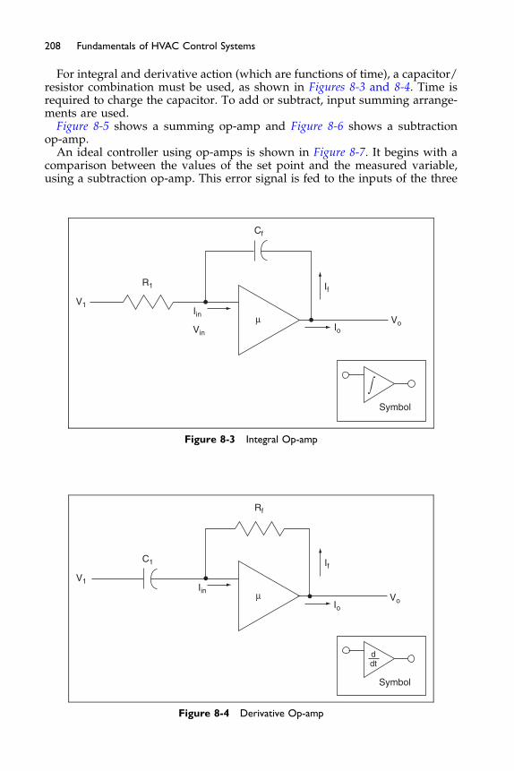
208 Fundamentals of HVAC Control Systems
For integral and derivative action (which are functions of time), a capacitor/resistor combination must be used, as shown in Figures 8-3 and 8-4. Time isrequired to charge the capacitor. To add or subtract, input summing arrange-ments are used.
Figure 8-5 shows a summing op-amp and Figure 8-6 shows a subtractionop-amp.
An ideal controller using op-amps is shown in Figure 8-7. It begins with acomparison between the values of the set point and the measured variable,using a subtraction op-amp. This error signal is fed to the inputs of the three
V1
R1
Cf
Iin
If
IoVo
Symbol
Vin
μ
Figure 8-3 Integral Op-amp
V1
C1
Rf
Iin
If
IoVo
Symbol
ddt
μ
Figure 8-4 Derivative Op-amp
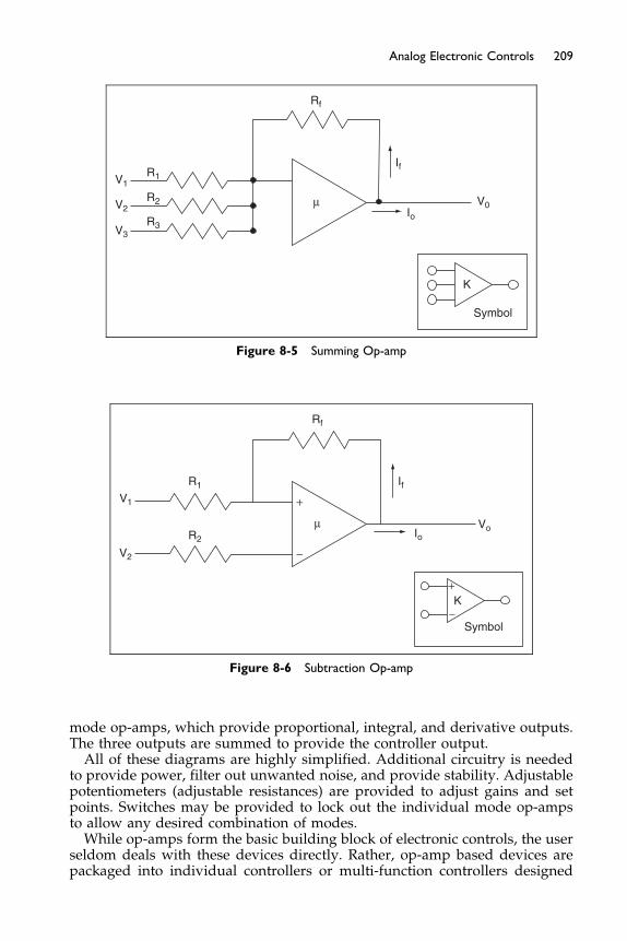
Rf
If
Ioμ
R1V1
V0V2
V3
R2
R3
K
Symbol
Figure 8-5 Summing Op-amp
V1
V2
R1
R2
Rf
If
Io
K
Vo
Symbol
μ
+
+
−
−
Figure 8-6 Subtraction Op-amp
209Analog Electronic Controls
mode op-amps, which provide proportional, integral, and derivative outputs.The three outputs are summed to provide the controller output.All of these diagrams are highly simplified. Additional circuitry is needed
to provide power, filter out unwanted noise, and provide stability. Adjustablepotentiometers (adjustable resistances) are provided to adjust gains and setpoints. Switches may be provided to lock out the individual mode op-ampsto allow any desired combination of modes.While op-amps form the basic building block of electronic controls, the user
seldom deals with these devices directly. Rather, op-amp based devices arepackaged into individual controllers or multi-function controllers designed
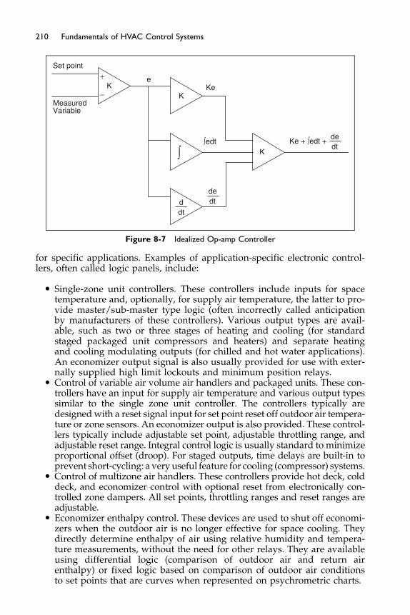
Set point
MeasuredVariable
KK
K
dedt
Ke
Ke + ∫edt +
e+
−
∫edt
dedtd
dt
Figure 8-7 Idealized Op-amp Controller
210 Fundamentals of HVAC Control Systems
for specific applications. Examples of application-specific electronic control-lers, often called logic panels, include:
� Single-zone unit controllers. These controllers include inputs for spacetemperature and, optionally, for supply air temperature, the latter to pro-vide master/sub-master type logic (often incorrectly called anticipationby manufacturers of these controllers). Various output types are avail-able, such as two or three stages of heating and cooling (for standardstaged packaged unit compressors and heaters) and separate heatingand cooling modulating outputs (for chilled and hot water applications).An economizer output signal is also usually provided for use with exter-nally supplied high limit lockouts and minimum position relays.
� Control of variable air volume air handlers and packaged units. These con-trollers have an input for supply air temperature and various output typessimilar to the single zone unit controller. The controllers typically aredesignedwith a reset signal input for set point reset off outdoor air tempera-ture or zone sensors. An economizer output is also provided. These control-lers typically include adjustable set point, adjustable throttling range, andadjustable reset range. Integral control logic is usually standard to minimizeproportional offset (droop). For staged outputs, time delays are built-in toprevent short-cycling: a very useful feature for cooling (compressor) systems.
� Control of multizone air handlers. These controllers provide hot deck, colddeck, and economizer control with optional reset from electronically con-trolled zone dampers. All set points, throttling ranges and reset ranges areadjustable.
� Economizer enthalpy control. These devices are used to shut off economi-zers when the outdoor air is no longer effective for space cooling. Theydirectly determine enthalpy of air using relative humidity and tempera-ture measurements, without the need for other relays. They are availableusing differential logic (comparison of outdoor air and return airenthalpy) or fixed logic based on comparison of outdoor air conditionsto set points that are curves when represented on psychrometric charts.
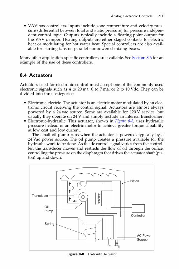
211Analog Electronic Controls
� VAV box controllers. Inputs include zone temperature and velocity pres-sure (differential between total and static pressure) for pressure indepen-dent control logic. Outputs typically include a floating-point output forthe VAV damper. Heating outputs are either staged contacts for electricheat or modulating for hot water heat. Special controllers are also avail-able for starting fans on parallel fan-powered mixing boxes.
Many other application-specific controllers are available. See Section 8.6 for anexample of the use of these controllers.
8.4 Actuators
Actuators used for electronic control must accept one of the commonly usedelectronic signals such as 4 to 20 ma, 0 to 7 ma, or 2 to 10 Vdc. They can bedivided into three categories:
� Electronic-electric. The actuator is an electric motor modulated by an elec-tronic circuit receiving the control signal. Actuators are almost alwayspowered by a 24 vac source. Some are available for 120 V service, butusually they operate on 24 V and simply include an internal transformer.
� Electronic-hydraulic. This actuator, shown in Figure 8-8, uses hydraulicpressure instead of an electric motor to achieve greater torque capabilityat low cost and low current.
The small oil pump runs when the actuator is powered, typically by a24 Vac power source. The oil pump creates a pressure available for thehydraulic work to be done. As the dc control signal varies from the control-ler, the transducer moves and restricts the flow of oil through the orifice,controlling the pressure on the diaphragm that drives the actuator shaft (pis-ton) up and down.
Controller
Piston
Transducer
OilPump
Spring
AC PowerSource
Figure 8-8 Hydraulic Actuator
212 Fundamentals of HVAC Control Systems
� Electronic-pneumatic. In this hybrid application, pneumatic actuators areused, powered through an I/P transducer (Chapter 7). Many designerscontinue to use pneumatic damper operators with electronic controllersbecause of their simplicity, power, and reliability, but this is gradually chang-ing as electronic-electric actuators becomemore commonand less expensive.
Actuators are available with and without spring return. Spring return is a use-ful feature that allows the actuator to actuate to a desired position upon a lossof power since the spring will perform the work required to get to that posi-tion. For electric and hydraulic actuators, it is common for the actuator toinclude an integral dc power supply to power the control circuit.
One way electronic actuators differ from typical pneumatic and electricactuators is that the control signal and the actuator power supply are fromseparate sources. With most pneumatic and electric controls, the signal is alsothe source of power. The exceptions are pneumatic actuators with pilot posi-tioners (discussed in Chapter 7), and electric actuators with spring return.
When using electric actuators, care should be taken into consideration aboutwhat voltage powers and forces the work of the actuator to be done, i.e. 24 vacor 120 vac. The issue to be careful about is the “VA” used by the actuator, andwhat size wiring you need to provide for it. For instance, for an actuator thatneeds 120 VA to operate, 1 amp to operate at 120 vac, and 5 amps to operate at24 vac are required. Make sure the wire is sized appropriately for the amper-age using the National Electric Code NFPA 70, or your local electrical code.And when using more than a few actuators on the same power source, becareful when using 24 vac, as there will be a voltage drop associated withthe wiring. Problems may occur with control device proper operation if thesupply voltage dips much below 22 vac.
8.5 Auxiliary Devices
Auxiliaries are similar to those used in electric systems. Relays will use sole-noid coils designed for the low voltages used in electronics, 24 vac, with con-tacts rated as required for the higher currents and voltages required by motorstarters and other electrical interfaces.
Relays are available that perform many of the same functions as pneumaticrelays except using analogous electronic signals. For instance, relays are avail-able for signal selection, signal reversing and signal sequencing. A relay simi-lar to a PE switch (pressure electric switch) is available to convert an analogsignal to one or more steps of control for two-position or step control logic.
Time clocks are electric motor driven devices that operate contacts when itstime set points are met. Electronic versions of the electric time clocks use lowvoltage integrated timing circuits to operate its contacts.
8.6 Example Applications
A single-zone system with chilled water-cooling and a two-stage electricheater is shown in Figure 8-9. The supply fan, outdoor air damper and asso-ciated controls are not shown for clarity. The control sequence for the system
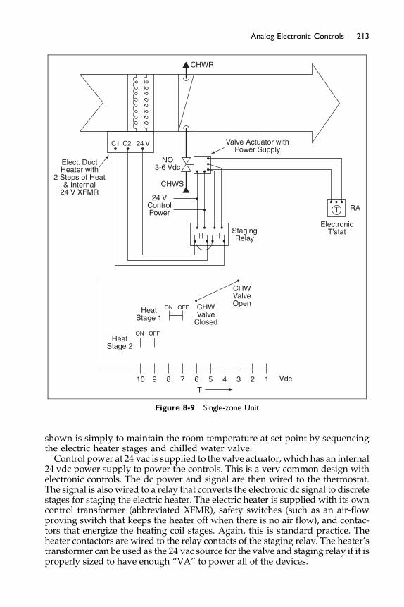
10
HeatStage 2
HeatStage 1
CHWValve
Closed
CHWValveOpen
StagingRelay
24 VControlPower
Elect. DuctHeater with
2 Steps of Heat& Internal
24 V XFMRCHWS
CHWR
NO3-6 Vdc
Valve Actuator withPower Supply
C1 C2 24 V
ElectronicT’stat
RAT
ON OFF
ON OFF
9 8 7 6T
5 4 3 2 1 Vdc
Figure 8-9 Single-zone Unit
213Analog Electronic Controls
shown is simply to maintain the room temperature at set point by sequencingthe electric heater stages and chilled water valve.Control power at 24 vac is supplied to the valve actuator, which has an internal
24 vdc power supply to power the controls. This is a very common design withelectronic controls. The dc power and signal are then wired to the thermostat.The signal is also wired to a relay that converts the electronic dc signal to discretestages for staging the electric heater. The electric heater is supplied with its owncontrol transformer (abbreviated XFMR), safety switches (such as an air-flowproving switch that keeps the heater off when there is no air flow), and contac-tors that energize the heating coil stages. Again, this is standard practice. Theheater contactors are wired to the relay contacts of the staging relay. The heater’stransformer can be used as the 24 vac source for the valve and staging relay if it isproperly sized to have enough “VA” to power all of the devices.
214 Fundamentals of HVAC Control Systems
For this design, it was desired that the heater should fail off if the controlsystem power failed, keeping the electric heat elements from possibly over-heating. (In other cases, we might wish the system to fail with heat on forfreeze protection. There are pluses and minuses to either approach.) If theheater must fail off, then the normally open contacts of the staging relay mustbe used, requiring that the thermostat be reverse-acting. This then requiresthat the cooling valve be normally open.
The positioner on the valve and the relay set points and differential areadjusted as shown in the Figure 8-9 to provide the desired staging andsequencing. This is very much like pneumatic controls (with PE switches usedfor staging the heater) except the 3 to 13 psig signal is now a 2 to 10 vdc signal.
A single-zone logic panel “controller” (see Section 7.3) could also have beenused to control this system. In place of the thermostat and staging relay wouldbe the logic controller, which could be purchased with built-in modulatingcooling output and multiple stages of heat, and a space sensor with set pointadjustment potentiometer. An optional supply air temperature sensor couldbe used for master/sub-master control. One advantage of using logic panelsin place of individual electronic controls is that no adjustments are requiredto ensure that cooling and heating stages are properly sequenced, therebysimplifying both start-up and future maintenance of the system. In most cases,logic panels are also less expensive.
Figure 8-10 shows a variable air volume system with economizer operatingwith the same sequence as the example in Chapter 7, except using electroniccontrols.
An electronic timeclock is used instead of an electric timeclock (althougheither could be used in either application). This often requires the use of arelay to power the starter circuit (as shown in Figure 8-10) because the contacton the electronic timeclock is often rated for low voltage and low current.
An electronic logic panel, designed specifically for this application, is usedto sequence the economizer and chilled water coil. If this were a packagedunit rather than a chilled water air handler, the controller would stage eachstep of cooling with built-in time delays to prevent short-cycling.
Power to the logic panel is shut off along with the supply fan. This is tokeep the controller from PID integral winding-up (Chapter 1) when the sys-tem is off, resulting in poor control when the system is first started. This is aparticularly important detail with direct expansion cooling systems, becausethe integral wind-up will usually cause the system to go to full cooling atstart-up instead of staging up gradually.
The logic panel also controls the economizer, sequencing it ahead of thechilled water valve. A double-throw outdoor air thermostat enables the econ-omizer in cool weather and disables it in hot weather. A minimum damperposition potentiometer is adjusted to maintain the minimum damper positionrequired for ventilation regardless of economizer signal.
The actuators in this case are 24 V electric actuators with spring return. Likepneumatic actuators, they return to their normal position (outdoor air damperand control valve closed) when 24 V power is removed via the interlock to thecurrent relay indicating fan status.
Static pressure is controlled in this example by an electric floating-pointcontroller, which is less expensive than the equivalent electronic controller(another example of how many control systems are actually hybrids of the
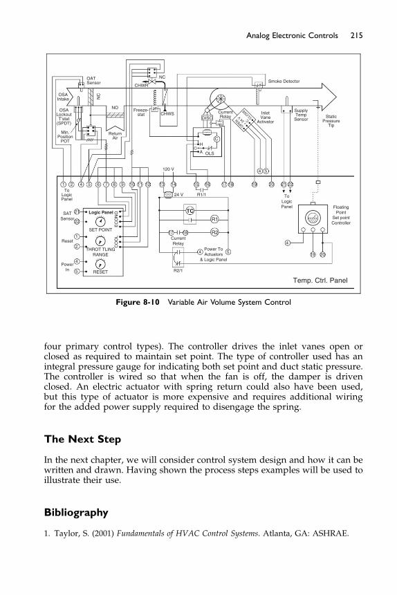
FloatingPoint
Set pointController
Temp. Ctrl. Panel
20
4
5
17 18
TC
R1
R2
4 5Power ToActuators
& Logic Panel
R2/1
CurrentRelay
SATSensor
Reset
PowerIn RESET
THROT TLINGRANGE
SET POINT
Logic Panel
CO
OL
EC
ON
O
4
2
1
22
21
1 2To
LogicPanel
OSAIntake
OATSensor
NC
NC
NO
ReturnAir
CHWR
CHWSDISC
CurrentRelay
InletVane
ActivatorOPEN
+ 24
VC
CLOSE Supply
TempSensor
Smoke Detector
StaticPressure
Tip
Freeze-stat
OSALockoutT’stat
(SPDT)
Min.Position
POT
4 5 6 8 9 10 11 12 13
120 V
24 V R1/1 ToLogicPanel
14 15
H
A OLS
16 17
C
18 19 20 21 22
54
7
19
Figure 8-10 Variable Air Volume System Control
215Analog Electronic Controls
four primary control types). The controller drives the inlet vanes open orclosed as required to maintain set point. The type of controller used has anintegral pressure gauge for indicating both set point and duct static pressure.The controller is wired so that when the fan is off, the damper is drivenclosed. An electric actuator with spring return could also have been used,but this type of actuator is more expensive and requires additional wiringfor the added power supply required to disengage the spring.
The Next Step
In the next chapter, we will consider control system design and how it can bewritten and drawn. Having shown the process steps examples will be used toillustrate their use.
Bibliography
1. Taylor, S. (2001) Fundamentals of HVAC Control Systems. Atlanta, GA: ASHRAE.
Chapter 9
Control Diagrams and Sequences
Contents of Chapter 9
Study Objectives of Chapter 99.1 Control Systems Design Criteria
9.2 Control Systems Design Process 9.3 Control Diagrams and Symbols 9.4 Control Sequences 9.5 Example Applications BibliographyStudy Objectives of Chapter 9
This chapter introduces how control systems are designed and how thedesign intent is conveyed using control diagrams (schematics), damperand valve schedules, parts lists, and written control sequences. Electric con-trols are drawn on ladder diagrams, which were covered in Chapter 2, Sec-tion 2.7. The process of designing a control system must begin with anunderstanding of what is to be controlled and how it is to be controlledbefore selecting the type of control device hardware required to implementthe desired logic. The hardware selection (be it self-powered, electric, analogelectronic, pneumatic, or digital) will be a function of the requirements ofthe process, the accuracy and reliability required, cost desired, etc. Moreadvanced control strategies are discussed in other courses and in the ASH-RAE Handbooks.
After studying this chapter, you should be able to:
Comprehend design concepts that will result in a workable and flexiblecontrol system.
Understand the responsibilities of the various designers and contractors inthe typical control system design and construction process.
Know how to create a control diagram using standard symbols.Comprehend the guidelines for writing a control sequence.
217Control Diagrams and Sequences
9.1 Control Systems Design Criteria
Designing HVAC control systems, like designing HVAC systems themselves,is a science but allows for different approaches. Every designer’s style differsand there are many right ways to control the same system.The critical first step towards success is to be absolutely clear about the
objective. For example, an office air-conditioning system has temperature,humidity, and outside air requirements to achieve during occupied hours. Ifgroups of offices are to be in a single control zone identify the fact. It may wellhave requirements for setback temperature and humidity control in OFFhours as well as particular performance in case of fire/smoke alarm or firedepartment control. Having these requirements written down, and agreedwith the client, makes for a solid foundation for controls design. This is partic-ularly the case with large client organizations and larger design offices, wherepeople with different views and expectations often join the project well afterthe design decisions have been made.There are several basic requirements for systems:
� The control system must meet the needs of the process.� The control system should control the process as directly as possible.� The control system must be designed to work with the HVAC system,
and vice versa.� The HVAC control system should minimize energy consumption.� The HVAC control system shouldmaintain indoor air quality requirements.� The cost of the HVAC control system must meet the budget.� The control system must be designed for maximum simplicity. As Albert
Einstein once said: “Everything should be as simple as possible, but notsimpler.”
The simplest systems have the best chance of being operated as intended.This is not to say that we must compromise the design goals expressed abovefor the sake of simplicity. The designer must balance the need for complexitywith the reality that complex systems are the most likely to work incorrectlydue to “bugs” in the design and the most likely to be misunderstood by thefacility operator or repair technician who must make the system operate inthe field. The ability of the maintenance team and available support shouldbe considered when making design and equipment choices. A school whichis one of many in a large city school district is very different from a schoolin a remote community, where maintenance expertise is very limited andany maintenance items may have to be flown in.Even the simplest of control systems requires good documentation and
training. Some control systems are necessarily complex because the HVACsystem or the process it serves is complex. It is very important to have aneffective training and useable documentation.Operators that follow in years to come must be able to find out and under-
stand how the system is designed to operate, and where components arephysically located. Therefore, detailed explanations of the design intentshould be included on plans. All software and programming must be turnedover to the end-user and copies kept in the operations room as well as inanother safe place. As-built drawings and data sheets must be transmitted
218 Fundamentals of HVAC Control Systems
through the design and contractor channels to the end-user files. Carefulattention to depicting locations of all sensors, thermostats, communicationlines, power wiring/tubing, pilot lights, valves, dampers, PRV’s, relays,switches, etc. on the as-built and maintenance and operation documentsshould be done. All cables, wires, and tubes should be marked permanentlywith a marker, in at least two places, and documented on the control diagramsor point lists. It is a good idea for the engineer to specify and follow up to ver-ify compliance. In any but the simplest system, formal commissioning pays offin initial performance and in ongoing operation and energy consumption.
9.2 Control Systems Design Process
The controls system designer must be able to convey not only the designintent (how the system is supposed to operate), but also who is responsiblefor performing the work and who is required to construct the control system.
Today, the advent of more complex control systems, and the variation in sys-tem architecture from one manufacturer to another, has led to more perfor-mance-based designs and specifications. In a performance-based design, theoperational characteristics that are desired are specified and the control systemprovided can provide a number of solutions in order to control the system tomeet this requirement. Ultimately, in most cases, the contractor is responsiblefor interpreting the intent of the contract documents, and the contractor shalldirect his staff, subcontractors and suppliers to comply.
Controls Contractor: The controls contractor is part of the controls design-and-construct team, along with the HVAC engineer. The controls contractormay also be the control system vendor, the manufacturer and/or distributorof the parts and components.
It is very important that the firm installing the electrical and mechanical con-trols is duly licensed and insured to do the work, as well as authorized andtrained by the controls manufacturer. For additional information on the respon-sibilities and actions required at various stage of the design and constructionprocess, readers are encouraged to read ASHRAE Guideline 1, CommissioningHVAC Systems.
9.3 Control Diagrams and Symbols
ASHRAE has published Standard 134-2005 Graphic Symbols for Heating,Ventilating, Air-Conditioning, and Refrigerating Systems, which includesstandard symbols to be used in the controls industry: a sample of symbolscan be seen in Figure 9-1. Many organizations have developed their ownlibrary of graphic symbols and it is wise to include on the controls drawingsa key to their meaning to avoid any misunderstandings.
The symbols cover four sections: air handling, piping, controls, and equip-ment. The graphic symbol may have two types of information added aboutparticular variations of device and detail about the device function. For exam-ple, a coil symbol may have CC – to indicate Cooling Coil – or HC – to indi-cate Heating Coil. Alternatively, the coil can be marked with a � for cooling
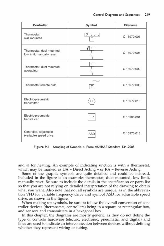
Controller Symbol Filename
Thermostat,wall mounted
Thermostat, duel mounted,low limit, manually reset C 15970.005
C 15970.001
T
T
T
EP
ASD
ET
T
C 15970.002
C 15972.003
C 15972.018
C 15960.001
C 15970.018
Thermostat, duct mounted,averaging
Thermostat remote bulb
Electric-preumatrictransmitter
Electric-preumatrictransducer
Controller, adjustable(variable) speed drive
Figure 9-1 Sampling of Symbols > From ASHRAE Standard 134-2005
219Control Diagrams and Sequences
and � for heating. An example of indicating unction is with a thermostat,which may be marked as DA – Direct Acting – or RA – Reverse Acting.Some of the graphic symbols are quite detailed and could be misread.
Included in the figure is an example: thermostat, duct mounted, low limit,manually reset. Be sure to include the details in the specification or parts listso that you are not relying on detailed interpretation of the drawing to obtainwhat you want. Also note that not all symbols are unique, as in the abbrevia-tion VFD for variable frequency drive and symbol ASD for adjustable speeddrive, as shown in the figure.When making up symbols, be sure to follow the overall convention of con-
troller devices (thermostats, controllers) being in a square or rectangular box,and sensors and transmitters in a hexagonal box.In this chapter, the diagrams are mostly generic; as they do not define the
type of controls hardware (electric, electronic, pneumatic, and digital) andlines are used to indicate an interconnection between devices without definingwhether they represent wiring or tubing.
220 Fundamentals of HVAC Control Systems
Generic control diagrams are generally acceptable for most HVAC designsfor bidding purposes because they, along with the written sequence of con-trols described in the next section, should sufficiently define the requirementsof the control system. (The generic diagrams for digital control systems takeon a slightly different appearance than the generic drawings here; if digitalcontrols are to be used, diagrams should be tailored for that purpose andwe will cover them in later chapters.)
9.4 Control Sequences
Controls are simply devices that try to duplicate the human thought process.With HVAC system controls, the controls are designed to carry out thethoughts and desires of the HVAC system designer. Because the HVAC sys-tem designer is probably not the person who will detail the controls systemdesign, possibly not the person who will program and commission the sys-tem, and seldom the person who must operate and maintain the system foryears to come, it is imperative that the designer convey his or her thoughts,about how the system is supposed to perform, clearly and without ambiguity.This is done through a written sequence of operation, also called a writtencontrol sequence.
Note that there are two fundamentally different ways of specifying a controlsystem: performance and detail. In the performance specification the resultingperformance is set out and described but the means to achieve this perfor-mance is left open. In the detailed specification, the components and how theyare to be connected are all defined. “The temperature control shall maintain73 � 2�F” is a performance specification and “Supply and install a modelABC temperature sensor and XYZ controller” is a detail specification. Manydesigners use a mix of the approaches, allowing the contractor freedom exceptwhere the designer wants a specific product for performance, reliability, clientwishes, or other reason. For the HVAC designer following the performancespecification approach, a clearly written sequence of operation is essentialbecause it is the means of conveying the desired control system’s performanceto the controls vendor or contractor.
Some guidelines for writing control sequences:
� Break the sequence into logical parts. First divide the system into majorsubsystems, such as air handlers, chiller plant and boiler plant, CAV,VAV, reheat coils, exhaust fans, isolation rooms, hoods, air flow moni-tors, etc. Then further subdivide each of these parts into individual con-trol blocks, such as start/stop (how and when will the equipment run),and a block for each controlled device and/or controlled variable. In theprevious chapter the variable volume system controls were in threeparts: fan start/stop; air velocity control by inlet guide vanes; tempera-ture and mixed air control. Although the parts interconnected, theyeach operated as a separate subsystem.
� When specifying an HVAC control loop, be sure it is clear what the controlpoint and controlled device are, and how the set point is determined. Typi-cal devices to control are temperature, pressure, carbon dioxide level,humidity, carbon monoxide level, filter pressure drop, flow, and velocity.
221Control Diagrams and Sequences
If certain control logic (such as P, PI), resets, and direct/reverse acting arerequired for acceptable performance, it also should be specified.
� Many HVAC control loops will need to have some type of enabling anddisabling interlock. This is important because PID control loops, whichare enabled when the equipment they control are “off”, can develop“integral windup” due to the long periods of time with its controlled var-iable signal is away from its set point. To solve this, the control loop canbe turned on and off with a status control point tied to the status of theequipment controlled, allowing for the control loop to be turned on andoff with respect to its equipment being on or off. This allows for the con-trol loop to start working closer to its target set point immediately uponits equipment starting.
� Always state the required or desired set point and range for control loops.Many times, this information is left up to the operator to set because setpoints are generally adjustable. But the control sequence should at leastprovide a guideline of the range of set points that the system wasdesigned to provide, and that will result in acceptable performance.
� In general, each controlled variable should be controlled by a single con-trol loop. If various devices affect a given controlled variable and a con-trol loop is provided for each, the control loops would have to becoordinated to be sure that only one is operational at any given time.For example, supply air temperature control for a system with an econo-mizer should have a single controller that sequences the chilled watervalve and economizer dampers. One controller should be used for eachprocess. All sensors that directly control the controlled devices shouldbe wired to that controller, where feasible. If two controllers are usedinstead of one, they must be enabled and disabled in sequence so thatone does not “fight” the other. Some extra sensors may be required,that will wire to both controllers, if they directly conflict with its operation.Also, if one controller loses power or communication, or if sensors and/ordevices wired to them affect other controllers, then this practice should beavoided. Generally, all control loops and sensors should have the capabil-ity to sense and alarm when there is a suspected and/or sensed failureand/or out-of-bounds response. In rare cases, where industrial high accu-racy control is required, double loops or cascaded loops may be used.
� For each controlled device, state not only how it should be controlledwhen the system is normally operating, but also how the device is to becontrolled when the system is shut off normally (such as by time sched-ule) or in an emergency (such as by a smoke detector, or fire alarm, orbad weather). For instance, when an air handler shuts off, typically it isbetter to have the outdoor air dampers to close to avoid infiltration andpossible coil freezing. Also, two-way control valves to close to reducepumping energy and piping losses may be desirable. If so, this must bespecifically stated in sequences.
� Specify the normal position of a controlled device if it is important to thedesign. For instance, we may want all heating valves to be normally-opento prevent freeze-ups in cold weather. If so, this must be stated insequences (or on schematics). If a normal position is not critical to thedesign, do not require one because with some hardware types (particu-larly electric and electronic controls) this will increase first-costs.
222 Fundamentals of HVAC Control Systems
� Specify the wiring and installation methods required such as plenumwiring only (plenum wiring has low flame and smoke generation proper-ties that are sufficiently limited for them to be approved for plenum use),conduit required, or a combination. Tell the contractor where to mountthe devices, such as on the ducts, on the walls and at what height, onthe top of the pipes, in the ceilings, etc.
� It is important that control sequences be as specific and detailed as possi-ble. All sequences should answer the questions who; what; when; where;how; and how much?
9.5 Example Applications
In this section, written sequences and generic control diagrams are discussedfor many typical HVAC applications. These applications, with some varia-tions, will be the basis of further examples to demonstrate how different con-trol system hardware and software types are applied.
These examples are written from the perspective of the HVAC systemdesign engineer who is attempting to convey the design intent and operatingsequence to a controls vendor/contractor (who will actually design moreintricate details of the controls upon its formal submittal and as-builts) andto future system operators.
Typical Single-Zone System
Figure 9-2 shows a single-zone unit with hydronic heating and cooling coils.A fan coil unit can also be a simple single zone system.
To develop a sequence of controls, the controlled devices, which are: thesupply fans’ motor; the hot water valve; the chilled water valve; and the out-door air damper must be identified. The controlled variable is the temperatureof the room being conditioned by this air handler. A room thermostat (a sen-sor and controller in the same enclosure) is used as the controller.
In addition, two safety devices are provided: a duct smoke detector and afreeze-stat. The smoke detector is required by most building codes (depend-ing on equipment size) to shut off the fan when smoke is detected to preventits recirculation to occupied spaces. The freeze-stat is typically required toshut down the fan and/or outside air damper in cold climates to prevent coilfreeze-ups should the hot water system fail. For this system , the sequencemight read:
� Start/stop. The system shall start and stop based on the time schedule set onthe timeclock. (Modern timeclocks will have a total annual format with holi-day and temporary day programming. Specify how many times each daythat this start-stop occurs, such as on at 7 a.m. – and then off at 8 p.m.)(If operation is desired after the normally scheduled “on” time, an “overrideor bypass” switch to allow is required for overriding and should be added tothe diagram.)
� Heating/cooling control. Heating and cooling shall be controlled to main-tain room temperature at set point (typically 70�F to 75�F, adjustable) bya single set point proportional room thermostat modulating two-way
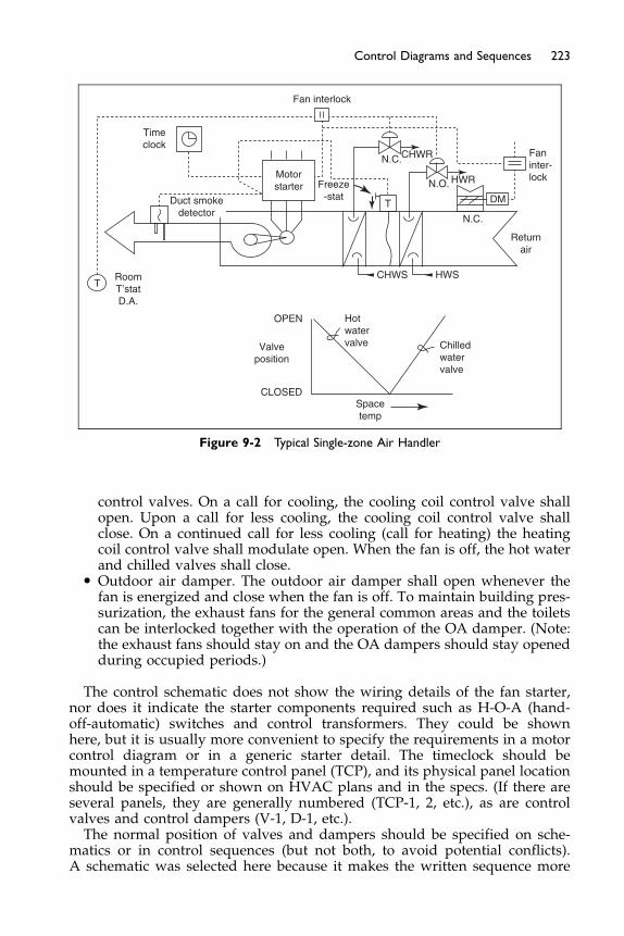
Faninter-lock
N.C.
DM
Returnair
CHWR
HWR
HWS
Chilledwatervalve
Hotwatervalve
T
Valveposition
RoomT’statD.A.
OPEN
CLOSED
Motorstarter Freeze
-statN.O.
N.C.
Timeclock
Spacetemp
CHWS
Fan interlock
TDuct smokedetector
Figure 9-2 Typical Single-zone Air Handler
223Control Diagrams and Sequences
control valves. On a call for cooling, the cooling coil control valve shallopen. Upon a call for less cooling, the cooling coil control valve shallclose. On a continued call for less cooling (call for heating) the heatingcoil control valve shall modulate open. When the fan is off, the hot waterand chilled valves shall close.
� Outdoor air damper. The outdoor air damper shall open whenever thefan is energized and close when the fan is off. To maintain building pres-surization, the exhaust fans for the general common areas and the toiletscan be interlocked together with the operation of the OA damper. (Note:the exhaust fans should stay on and the OA dampers should stay openedduring occupied periods.)
The control schematic does not show the wiring details of the fan starter,nor does it indicate the starter components required such as H-O-A (hand-off-automatic) switches and control transformers. They could be shownhere, but it is usually more convenient to specify the requirements in a motorcontrol diagram or in a generic starter detail. The timeclock should bemounted in a temperature control panel (TCP), and its physical panel locationshould be specified or shown on HVAC plans and in the specs. (If there areseveral panels, they are generally numbered (TCP-1, 2, etc.), as are controlvalves and control dampers (V-1, D-1, etc.).The normal position of valves and dampers should be specified on sche-
matics or in control sequences (but not both, to avoid potential conflicts).A schematic was selected here because it makes the written sequence more

224 Fundamentals of HVAC Control Systems
understandable. In this example, the hot water valve was selected to be nor-mally open so that if the controller fails, for some reason, hot water flow couldbe made to flow through the coil by simply removing its control power. Thismight be used to prevent a coil freeze-up, or in cold climates it can be consid-ered life safety. The controller must be direct-acting to correspond to the nor-mally open hot water valve and the heating medium. This may or may not beincluded in the diagram and written sequence. If it were not specified, thecontrols vendor would be responsible for making the selection.
To correspond with the action of the controller above, the chilled water valvemust be normally-closed. It also must have a control range that is sequencedwith that of the heating valve. The control ranges may be shown on schematics,but their selection is often left up to the controls vendor or contractor.
For information, hot water pre-heat coils or electric heat is used to preventthe freezing of coils and other devices in cold weather. When heat is not avail-able, sometimes just flow though the coils is initiated by the control systemwhen freezing conditions apply, so that the coils can use the heat in the “pip-ing system” to slow down the freezing effect. Heating reheat coils can also beuseful to provide for dehumidification when needed and allowed by code.
On many systems, the designer will specify alarms that will advise theowner and operator that a control system or equipment failure has occurred,so a fast response and repair can be initiated.
In practice, many valves and actuators are now designed to permit the con-trolled device to be normally-open or normally-closed depending on what thedesigner wants.
The sequence specifies that the flow of hot and chilled water be shut offwhen the fan is not running, potentially reducing pump energy, piping, andcoil heat losses. This could be done most conveniently by using normally-closed valves so that we need only interlock the valve’s power source to thesupply fan to close it when the fan is off. To do this, using a normally-openvalve, some means of driving the valve closed when the fan is off must beprovided. This would be a hardware requirement implied by specifying thatthe valve be normally-open but shut when the fan is off. (For cooling systems,it is advisable to shut off the cooling valve when the fan system is off, as itmay produce condensate and waste energy when not being used.)
Using a single controller (thermostat) means we have a single set point forboth heating and cooling. To save energy, wemaywish to have a lower set pointin the winter than in the summer. For instance, we may want to maintain thespace at 70�F for heating and 75�F for cooling. Between these two set points,we would want both valves closed. This is called the controller deadband,which is the range over which a change in controlled variable causes no changesto any controlled device. To create a deadband using proportional controls, wecould adjust the control ranges over which the chilled and hot water valvesoperated to create a gap in between them. Using pneumatic controls as an exam-ple, we could operate the hot water valve over a 2 to 6 psi range and the chilledwater valve over a 10 to 14 psi range, leaving a gap from 6 psi to 10 psi whereboth valves were closed. The temperature range that corresponds to this signalrange would depend on the throttling range of the controller. Typically, pneu-matic thermostats are adjusted to provide a 2.5 psi per �F throttling range,whichwould mean the 4 psi gap between 6 psi and 10 psi would correspond to a tem-perature dead band of about 1.6�F, or 2�F, which could be 70–72�F.
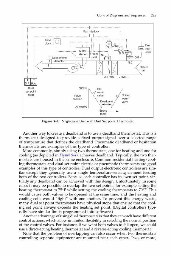
Deadband
Dualset point
t’stat
TD.A.
TR.A.
Chilledwatervalve
Hotwatervalve
Spacetemp
Valveposition
OPEN
CLOSED
Faninter-lock
N.C.
DM
Returnair
CHWR
HWR
HWS
Motorstarter Freeze
-statN.O.
N.C.
Timeclock
CHWS
Fan interlock
TDuct smokedetector
Figure 9-3 Single-zone Unit with Dual Set point Thermostat
225Control Diagrams and Sequences
Another way to create a deadband is to use a deadband thermostat. This is athermostat designed to provide a fixed output signal over a selected rangeof temperature that defines the deadband. Pneumatic deadband or hesitationthermostats are examples of this type of controller.More commonly, simply using two thermostats, one for heating and one for
cooling (as depicted in Figure 9-4), achieves deadband. Typically, the two ther-mostats are housed in the same enclosure. Common residential heating/cool-ing thermostats and dual set point electric or pneumatic thermostats are goodexamples of this type of controller. Dual output electronic controllers are sim-ilar except they generally use a single temperature-sensing element feedingboth of the two controllers. Because each controller has its own set point, vir-tually any deadband can be achieved with this design. Unfortunately, in somecases it may be possible to overlap the two set points; for example setting theheating thermostat to 75�F while setting the cooling thermostats to 70�F. Thiswould cause both valves to be opened at the same time, and the heating andcooling coils would “fight” with one another. To prevent this energy waste,many dual set point thermostats have physical stops that ensure that the cool-ing set point always exceeds the heating set point. (Digital controllers typi-cally have similar limits programmed into software.)Another advantage of usingdual thermostats is that they can eachhavedifferent
control actions, which allow unlimited flexibility in selecting the normal positionof the control valves. For instance, if we want both valves to fail open, we coulduse a direct-acting heating thermostat and a reverse-acting cooling thermostat.Note that the problem of overlapping can also occur when two thermostats
controlling separate equipment are mounted near each other. Two, or more,

Air flow
M
Coo
ling
coil
Figure 9-4 Face and Bypass Damper Arrangement
226 Fundamentals of HVAC Control Systems
self-contained units that can both heat and cool installed in the same room isan example.
Typical Constant Air Volume System with Face and Bypass Dampers
For each air-handling unit, its chilled water valve shall be modulated to main-tain discharge air temperature set point at 55�F (adjustable) unless it is in itsheating mode.
Face and bypass dampers are used to vary the volume of air through a coilor bypassing it. The arrangement is shown in Figure 9-4. Due to the relativelyhigher resistance of the coil, the bypass damper is much smaller than the coildamper. The dampers here are shown as being driven by a single motor withthe bypass well open and the coil flow somewhat closed off.
The face and bypass damper for this example is around the cooling coil.(Note, it can be around the heating coil or both for other designs.)
The face and bypass damper shall modulate to maintain a room or returnair set point of 72�F (adjustable). As room or return air temperature risesabove set point, the actuator shall command open face damper (more air flowacross cooling coil) while closing bypass damper, until the desired return airtemperature set point is achieved.
As the room or return air temperature falls below the set point 72�F (adjus-table), the chilled water valve will be commanded closed, and face and bypassdampers shall be positioned to bypass position. On continued drop in roomtemperature, the face and bypass shall go to the full bypass position, andthe hot water valve or electric heat shall be modulated or staged on asrequired to maintain heating set point.
Provide a minimum of 1�F of deadband where no control action occurs.Provide a fail-safe position for the face and bypass (F&B) damper to positionitself. When the F&B damper is in the full face or full bypass position it issometimes advisable to close the valve that is not being used. (Note, for exam-ple, in a cold climate, the fail-safe position may be in the bypass position.)
The supply fan and outdoor air damper/interlocked exhaust fans shall becontrolled on and off together, on its own separate occupied time schedule.
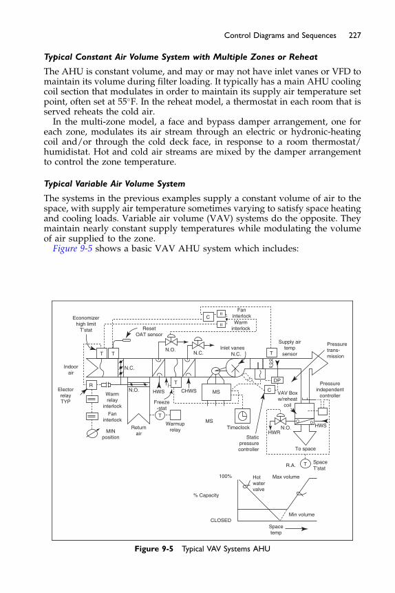
227Control Diagrams and Sequences
Typical Constant Air Volume System with Multiple Zones or Reheat
The AHU is constant volume, and may or may not have inlet vanes or VFD tomaintain its volume during filter loading. It typically has a main AHU coolingcoil section that modulates in order to maintain its supply air temperature setpoint, often set at 55�F. In the reheat model, a thermostat in each room that isserved reheats the cold air.In the multi-zone model, a face and bypass damper arrangement, one for
each zone, modulates its air stream through an electric or hydronic-heatingcoil and/or through the cold deck face, in response to a room thermostat/humidistat. Hot and cold air streams are mixed by the damper arrangementto control the zone temperature.
Typical Variable Air Volume System
The systems in the previous examples supply a constant volume of air to thespace, with supply air temperature sometimes varying to satisfy space heatingand cooling loads. Variable air volume (VAV) systems do the opposite. Theymaintain nearly constant supply temperatures while modulating the volumeof air supplied to the zone.Figure 9-5 shows a basic VAV AHU system which includes:
Economizerhigh limit
T’stat ResetOAT sensor
N.C.Indoorair
TMSWarmup
relay Timeclock
N.O.
Returnair
R
Freeze-stat
HWS CHWSWarmrelay
interlock
Faninterlock
MINposition
ElectorrelayTYP
T
T
N.O.N.C.
Inlet vanesN.C.
Supply airtemp
sensor
Pressureindependent
controller
To space
R.A.SpaceT’stat
VAV Boxw/reheat
coil
HWRN.O. HWS
Pressuretrans-mission
Staticpressurecontroller
FaninterlockWarm
interlock
MS
DP
C
C
Max volume
Min volume
Hotwatervalve
% Capacity
100%
CLOSEDSpacetemp
T T
T
Figure 9-5 Typical VAV Systems AHU
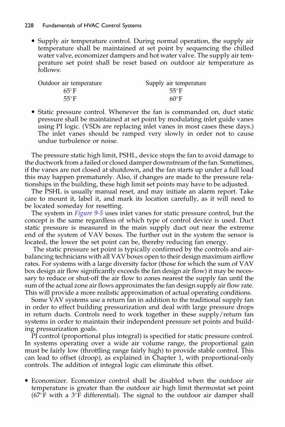
228 Fundamentals of HVAC Control Systems
� Supply air temperature control. During normal operation, the supply airtemperature shall be maintained at set point by sequencing the chilledwater valve, economizer dampers and hot water valve. The supply air tem-perature set point shall be reset based on outdoor air temperature asfollows:
Outdoor air temperature Supply air temperature65�F 55�F55�F 60�F
� Static pressure control. Whenever the fan is commanded on, duct staticpressure shall be maintained at set point by modulating inlet guide vanesusing PI logic. (VSDs are replacing inlet vanes in most cases these days.)The inlet vanes should be ramped very slowly in order not to causeundue turbulence or noise.
The pressure static high limit, PSHL, device stops the fan to avoid damage tothe ductwork froma failed or closed damper downstreamof the fan. Sometimes,if the vanes are not closed at shutdown, and the fan starts up under a full loadthis may happen prematurely. Also, if changes are made to the pressure rela-tionships in the building, these high limit set points may have to be adjusted.
The PSHL is usually manual reset, and may initiate an alarm report. Takecare to mount it, label it, and mark its location carefully, as it will need tobe located someday for resetting.
The system in Figure 9-5 uses inlet vanes for static pressure control, but theconcept is the same regardless of which type of control device is used. Ductstatic pressure is measured in the main supply duct out near the extremeend of the system of VAV boxes. The further out in the system the sensor islocated, the lower the set point can be, thereby reducing fan energy.
The static pressure set point is typically confirmed by the controls and air-balancing technicians with all VAV boxes open to their designmaximum airflowrates. For systems with a large diversity factor (those for which the sum of VAVbox design air flow significantly exceeds the fan design air flow) it may be neces-sary to reduce or shut-off the air flow to zones nearest the supply fan until thesum of the actual zone air flows approximates the fan design supply air flow rate.This will provide a more realistic approximation of actual operating conditions.
Some VAV systems use a return fan in addition to the traditional supply fanin order to effect building pressurization and deal with large pressure dropsin return ducts. Controls need to work together in these supply/return fansystems in order to maintain their independent pressure set points and build-ing pressurization goals.
PI control (proportional plus integral) is specified for static pressure control.In systems operating over a wide air volume range, the proportional gainmust be fairly low (throttling range fairly high) to provide stable control. Thiscan lead to offset (droop), as explained in Chapter 1, with proportional-onlycontrols. The addition of integral logic can eliminate this offset.
� Economizer. Economizer control shall be disabled when the outdoor airtemperature is greater than the outdoor air high limit thermostat set point(67�F with a 3�F differential). The signal to the outdoor air damper shall
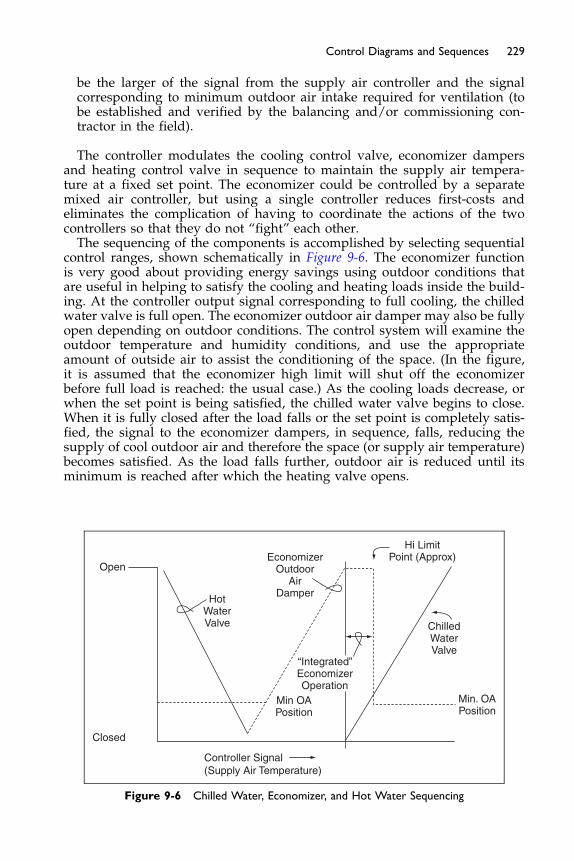
229Control Diagrams and Sequences
be the larger of the signal from the supply air controller and the signalcorresponding to minimum outdoor air intake required for ventilation (tobe established and verified by the balancing and/or commissioning con-tractor in the field).
The controller modulates the cooling control valve, economizer dampersand heating control valve in sequence to maintain the supply air tempera-ture at a fixed set point. The economizer could be controlled by a separatemixed air controller, but using a single controller reduces first-costs andeliminates the complication of having to coordinate the actions of the twocontrollers so that they do not “fight” each other.The sequencing of the components is accomplished by selecting sequential
control ranges, shown schematically in Figure 9-6. The economizer functionis very good about providing energy savings using outdoor conditions thatare useful in helping to satisfy the cooling and heating loads inside the build-ing. At the controller output signal corresponding to full cooling, the chilledwater valve is full open. The economizer outdoor air damper may also be fullyopen depending on outdoor conditions. The control system will examine theoutdoor temperature and humidity conditions, and use the appropriateamount of outside air to assist the conditioning of the space. (In the figure,it is assumed that the economizer high limit will shut off the economizerbefore full load is reached: the usual case.) As the cooling loads decrease, orwhen the set point is being satisfied, the chilled water valve begins to close.When it is fully closed after the load falls or the set point is completely satis-fied, the signal to the economizer dampers, in sequence, falls, reducing thesupply of cool outdoor air and therefore the space (or supply air temperature)becomes satisfied. As the load falls further, outdoor air is reduced until itsminimum is reached after which the heating valve opens.
Open
Closed
Controller Signal(Supply Air Temperature)
HotWaterValve
EconomizerOutdoor
AirDamper
“Integrated”EconomizerOperation
ChilledWaterValve
Hi LimitPoint (Approx)
Min. OAPosition
Min OAPosition
Figure 9-6 Chilled Water, Economizer, and Hot Water Sequencing
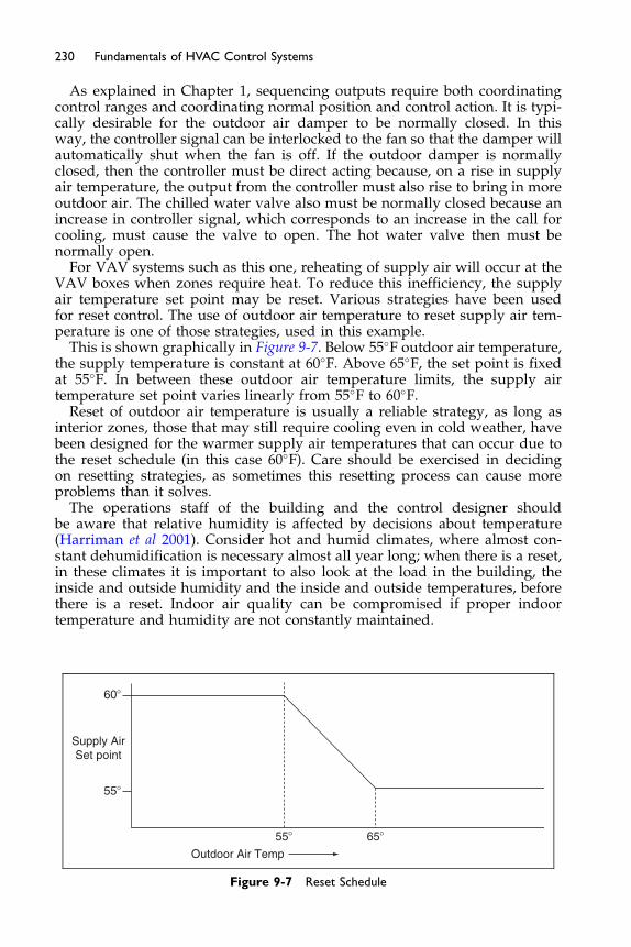
230 Fundamentals of HVAC Control Systems
As explained in Chapter 1, sequencing outputs require both coordinatingcontrol ranges and coordinating normal position and control action. It is typi-cally desirable for the outdoor air damper to be normally closed. In thisway, the controller signal can be interlocked to the fan so that the damper willautomatically shut when the fan is off. If the outdoor damper is normallyclosed, then the controller must be direct acting because, on a rise in supplyair temperature, the output from the controller must also rise to bring in moreoutdoor air. The chilled water valve also must be normally closed because anincrease in controller signal, which corresponds to an increase in the call forcooling, must cause the valve to open. The hot water valve then must benormally open.
For VAV systems such as this one, reheating of supply air will occur at theVAV boxes when zones require heat. To reduce this inefficiency, the supplyair temperature set point may be reset. Various strategies have been usedfor reset control. The use of outdoor air temperature to reset supply air tem-perature is one of those strategies, used in this example.
This is shown graphically in Figure 9-7. Below 55�F outdoor air temperature,the supply temperature is constant at 60�F. Above 65�F, the set point is fixedat 55�F. In between these outdoor air temperature limits, the supply airtemperature set point varies linearly from 55�F to 60�F.
Reset of outdoor air temperature is usually a reliable strategy, as long asinterior zones, those that may still require cooling even in cold weather, havebeen designed for the warmer supply air temperatures that can occur due tothe reset schedule (in this case 60�F). Care should be exercised in decidingon resetting strategies, as sometimes this resetting process can cause moreproblems than it solves.
The operations staff of the building and the control designer shouldbe aware that relative humidity is affected by decisions about temperature(Harriman et al 2001). Consider hot and humid climates, where almost con-stant dehumidification is necessary almost all year long; when there is a reset,in these climates it is important to also look at the load in the building, theinside and outside humidity and the inside and outside temperatures, beforethere is a reset. Indoor air quality can be compromised if proper indoortemperature and humidity are not constantly maintained.
55�
60�
55�
Supply AirSet point
65�
Outdoor Air Temp
Figure 9-7 Reset Schedule
231Control Diagrams and Sequences
The above specification and discussion are written in narrative, descriptivelanguage. Many organizations now use plain language – short simple sen-tences, and bulleted items, as the following example, which is modified fromCtrlSpecBuilder.com. This system is similar to the variable volume system abovewith the addition of controlling the relief fan by building pressure compared tooutside pressure and it has more alarms than we have previously considered.
Variable Air Volume – AHU – Sequence of Operations:Run Conditions - Scheduled: The unit shall run based upon an operator
adjustable schedule.Freeze Protection: The unit shall shut down and generate an alarm upon
receiving a freezestat status. Manual reset shall be required at operatorpanel.High Static Pressure Shutdown: The unit shall shut down and generate an
alarm upon receiving a high static pressure shutdown signal. Manual resetshall be required at operator panel.Supply Air Smoke Detection: The unit shall shut down and generate an
alarm upon receiving a supply air smoke detector status.Supply Fan: The supply fan shall run anytime the unit is commanded to
run, unless shutdown on safeties. To prevent short cycling, the supply fanshall have a user definable (1-10 minutes) minimum runtime.Alarms shall be provided as follows:
� Supply Fan Failure: Commanded on, but the status is off.� Supply Fan in Hand: Commanded off, but the status is on.
Supply Air Duct Static Pressure Control: The controller shall measure ductstatic pressure and modulate the supply fan VFD speed to maintain a ductstatic pressure set point. The speed shall not drop below 30% (adjustable).
� The initial duct static pressure set point shall be 1.5in H2O (adjustable).
Alarms shall be provided as follows:
� High Supply Air Static Pressure: If the supply air static pressure is above2.0in H2O (adjustable).
� Low Supply Air Static Pressure: If the supply air static pressure is lessthan 1.0in H2O (adjustable).
� Supply Fan VFD Fault.
Return Fan: The return fan shall run whenever the supply fan runs.Alarms shall be provided as follows:
� Return Fan Failure: Commanded on, but the status is off.� Return Fan in Hand: Commanded off, but the status is on.� Return Fan VFD Fault.
Building Static Pressure Control: The controller shall measure buildingstatic pressure and modulate the return fan VFD speed to maintain a buildingstatic pressure set point of 0.05in H2O (adjustable) above outside pressure.The return fan VFD speed shall not drop below 30% (adjustable).
232 Fundamentals of HVAC Control Systems
Alarms shall be provided as follows:
� High Building Static Pressure: If the building air static pressure is 0.1inH2O (in H2O is inches of water, just the same as ‘in wg’ that we used ear-lier in the text) (adjustable).
� Low Building Static Pressure: If the building air static pressure is -0.05inH2O (adjustable).
Supply Air Temperature Set point - Optimized:� The initial supply air temperature set point shall be 55�F (adjustable)
when the outside temperature is above 65�F.� As outside temperature drops from 65�F to 55�F, the set point shall incre-
mentally reset up to 60�F (adjustable) and remain at 60�F for tempera-tures below 55�F.
Cooling Coil Valve: The controller shall measure the supply air tempera-ture and modulate the cooling coil valve to maintain its cooling set point.
The cooling shall be enabled whenever:
� Outside air temperature is greater than 60�F (adjustable).� AND the economizer (if present) is disabled or fully open.� AND the supply fan status is on.� AND the heating (if present) is not active.
The cooling coil valve shall open to 50% (adjustable) whenever the freezestatis on.
Alarms shall be provided as follows:
� High Supply Air Temp: If the supply air temperature is above 58�F(adjustable).
Heating Coil Valve: The controller shall measure the supply air tempera-ture and modulate the heating coil valve to maintain its heating set point.
The heating shall be enabled whenever:
� Outside air temperature is less than 65�F (adjustable).� AND the supply fan status is on.� AND the cooling is not active.
The heating coil valve shall open whenever:
� Supply air temperature drops from 40 �F to 35 �F (adjustable).� OR the freezestat is on.
Alarms shall be provided as follows:
� Low Supply Air Temp: If the supply air temperature is below 50�F (adjus-table).
Cooling Coil Pump: The recirculation pump shall run whenever:
� The cooling coil valve is enabled.� OR the freezestat is on.
233Control Diagrams and Sequences
Alarms shall be provided as follows:
� Cooling Coil Pump Failure: Commanded on, but the status is off.� Cooling Coil Pump in Hand: Commanded off, but the status is on.
Economizer: The controller shall measure the mixed air temperature andmodulate the economizer dampers in sequence to maintain a set point 2�F(adjustable) less than the supply air temperature set point. The outside airdampers shall maintain a minimum adjustable position of 20% (adjustable)open whenever occupied.The economizer shall be enabled whenever:
� Outside air temperature is less than 65�F (adjustable).� AND the outside air enthalpy is less than 22 Btu/lb (adjustable)� AND the outside air temperature is less than the return air temperature.� AND the outside air enthalpy is less than the return air enthalpy.� AND the supply fan status is on.
The economizer shall close whenever:
� Mixed air temperature drops from 40�F to 35�F (adjustable)� OR the freezestat is on.� OR on loss of supply fan status.
The outside and exhaust air dampers shall close and the return air dampershall open when the unit is off.
Minimum Outside Air Ventilation: When in the occupied mode, the control-ler shall measure the outside airflow and modulate the outside air dampers tomaintain the properminimumoutside air ventilation, overriding normal dampercontrol. Ondroppingoutside airflow, the controller shallmodulate the outside airdampers open to maintain the outside airflow set point (adjustable).Humidifier Control: The controller shall measure the return air humidity
and modulate the humidifier to maintain a set point of 40% rh (adjustable).The humidifier shall be enabled whenever the supply fan status is on.The humidifier shall turn off whenever:
� Supply air humidity rises above 90% rh.� OR on loss of supply fan status.
Alarms shall be provided as follows:
� High Supply Air Humidity: If the supply air humidity is greater than 90%rh (adjustable).
� Low Supply Air Humidity: If the supply air humidity is less than 40% rh(adjustable).
Prefilter Differential Pressure Monitor: The controller shall monitor thedifferential pressure across the prefilter.

234 Fundamentals of HVAC Control Systems
Alarms shall be provided as follows:
� Prefilter Change Required: Prefilter differential pressure exceeds a userdefinable limit (adjustable).
Final Filter Differential Pressure Monitor: The controller shall monitor thedifferential pressure across the final filter.
Alarms shall be provided as follows:
� Final Filter Change Required: Final filter differential pressure exceeds auser definable limit (adjustable).
Mixed Air Temperature: The controller shall monitor the mixed air temper-ature and use as required for economizer control (if present) or preheatingcontrol (if present).
Alarms shall be provided as follows:
� High Mixed Air Temp: If the mixed air temperature is greater than 90�F(adjustable).
� Low Mixed Air Temp: If the mixed air temperature is less than 45�F(adjustable).
Return Air Humidity: The controller shall monitor the return air humidityand use as required for economizer control (if present) or humidity control(if present).
Alarms shall be provided as follows:
� High Return Air Humidity: If the return air humidity is greater than 60%(adjustable).
� Low Return Air Humidity: If the return air humidity is less than 30%(adjustable).
Return Air Temperature: The controller shall monitor the return air temper-ature and use as required for set point control or economizer control (ifpresent).
Alarms shall be provided as follows:
� High Return Air Temp: If the return air temperature is greater than 90�F(adjustable).
� Low Return Air Temp: If the return air temperature is less than 45�F(adjustable).
Supply Air Temperature: The controller shall monitor the supply airtemperature.
Alarms shall be provided as follows:
� High Supply Air Temp: If the supply air temperature is greater than 60�F(adjustable).
� Low Supply Air Temp: If the supply air temperature is less than 45�F(adjustable).
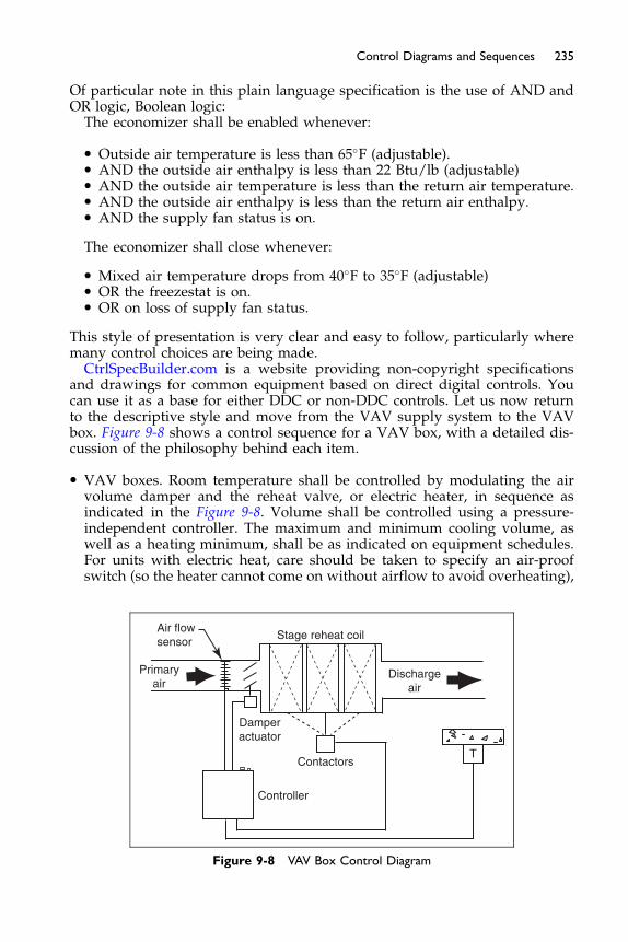
235Control Diagrams and Sequences
Of particul ar note in this plain languag e specif ication is the use of AND andOR logi c, Boolean logic:The economize r shall be enabled whene ver:
� Outsi de air te mperatur e is less than 65 � F (adjus table).� AN D the outsid e air enth alpy is less than 22 Btu/lb (adju stable)� AN D the outside air tempe rature is less than the retu rn air temp erature.� AN D the outsid e air enth alpy is less than the re turn air enth alpy.� AN D the supp ly fan status is on.
The economize r shall close wh eneve r:
� Mi xed air tempe rature drops from 40 � F to 35� F (adjus table)� OR the freeze stat is on.� OR on loss of supp ly fan status.
This style of presentation is very clear and easy to follow, particularly wheremany control choices are being made.Ctr lSpecBuild er.com is a we bsite providin g non-cop yright specif ications
and drawings for common equipment based on direct digital controls. Youcan use it as a base for either DDC or non-DDC controls. Let us now returnto the descriptive style and move from the VAV supply system to the VAVbox. Figure 9-8 shows a control sequence for a VAV box, with a detailed dis-cussion of the philosophy behind each item.
� VAV boxes. Room temperature shall be controlled by modulating the airvolume damper and the reheat valve, or electric heater, in sequence asindicated in the Figure 9-8. Volume shall be controlled using a pressure-independent controller. The maximum and minimum cooling volume, aswell as a heating minimum, shall be as indicated on equipment schedules.For units with electric heat, care should be taken to specify an air-proofswitch (so the heater cannot come on without airflow to avoid overheating),
Air flowsensor
Primaryair
Stage reheat coil
Dischargeair
Damperactuator
Contactors
Controller
T
Figure 9-8 VAV Box Control Diagram
236 Fundamentals of HVAC Control Systems
as well as thermal protection at the electric heater, so that potential fire con-ditions can be avoided. Power for the control system may be wired via alow voltage transformer attached to the electric heater, or, in the case ofhot water heat, the power would be provided externally. This sequencereferences pressure-independent control.
Early “pressure-dependant” VAV systems simply used a damper mounted inthe ductwork that was directly controlled by the space thermostat. As spacetemperature increased, the VAV damper opened. As the temperature in thespace fell, the VAV damper closed until at zero loads (when the thermostatwas satisfied) the VAV box would shut completely, with some (and some-times, significant) leakage. If a minimum flow was required, the dampercould be linked so that it would not close all the way to shut-off.
This type of control is called pressure-dependent because the amount of airsupplied to the space is a function of the pressure in the supply air system,not just of the thermostat signal. A change in system pressure could cause thesupply air to the space to change, and velocities to increase, possibly causingnoise and overcooling or under cooling the space before the thermostat is ableto compensate. This change in supply air pressure could be caused by the open-ing and closing of VAV boxes in the system causing severe airflow fluctuation.
This pressure-dependant control is rarely used as it has caused so manyproblems in the larger systems. In some smaller systems, where noise, accu-racy, ventilation effectiveness, and comfort are not as important, it is still usedoccasionally. The first cost is typically much more economical than pressure-independent systems.
To overcome this problem, pressure independent controls were developed.These controls use two cascading control loops, meaning the control loops arechained together with the output of one establishing the set point of the other.The first loop (the space thermostat) controls space temperature. The outputfrom this loop is fed to the second controller as the reset signal, setting the air-flow set point required to cool the space. The set point range can be limited toboth aminimum (cool and heat) andmaximumairflow rate. The second control-ler modulates the VAV damper to maintain the air volume at this set point.
Air volume, velocity times its fixed duct area (CFM), is measured using avelocity pressure averaging and amplifying sensor that often has fairly sophis-ticated configurations (such as rings or crosses), so that accurate measurementsof air velocity can be made even if inlet duct configurations are not ideal andeven when flows are low. (See the ASHRAE Handbooks for more informationon this subject.) Its operation is ‘independent’ of the changing supply duct pres-sure, although it still requires an acceptable range of duct static pressure in orderto operate normally, usually 1–2 in of water column pressure.
The availability of the maximum volume limit is very useful during systembalancing. The VAV box can be set to maintain the design air flow rate to thezone while the balancer adjusts manual volume dampers to achieve thedesired distribution of air among the rooms served by the zone. The maxi-mum volume limiter is also useful in preventing excess supply that can benoisy and objectionable. This might occur during early morning operationwhen spaces are warm and require greater than design airflow to cool down.
The capability to limit minimum volume is important to ensure that ade-quate airflow is provided to maintain minimum ventilation rates for accept-able indoor air quality. The thermal loads in the space (which dictate the

237Control Diagrams and Sequences
amount of air supplied by the VAV box) are not always in synch with the ven-tilation requirements, which are a function of occupancy and the emissionrates of people, pollutants from furnishings and office equipment.The minimum volume control can be used to ensure that sufficient supply air
is provided regardless of thermal load; this also promotes and maintainsproper building pressurization as long as the exhaust and ventilation operation(and volumes) are coordinated into the control system as well. Pressure-inde-pendent box controls are preferred over pressure-dependant for many reasons,including bothminimum andmaximum flow rates can be controlled regardlessof duct pressure, and flow rates are a function of available duct pressure.Minimum volume control is also essential for reheat boxes (where used to
provide space temperature or heating), which must be able to maintain a min-imum flow and temperature to effectively heat the space. Reheat boxes behavelike cooling-only boxes when the space is warm. As the space cools, the airvolume slows to its minimum amount, and while maintaining minimum vol-ume the air is reheated.The reheat box function is also used to heat the cold air flowing into the
room when the room thermostat is calling for heat. The volume cannot betoo low or the air supplied will be too warm and buoyant, and will not mixwell with the air in the space, resulting in discomfort and possibly inadequateventilation in the occupied zone.Remember the supply air from the VAV fan system is cool so, before any use-
ful heating can take place, the air must first be reheated up to the space temper-ature to provide heating. Some VAV box controllers have the ability to controlto dual minimum set points: one during cooling operation to maintain mini-mum ventilation rates, and a higher set point during peak heating operation.Some control systems allow the supply air to be reset based on the return air
from the spaces so that energy can be conserved during intermediate tempera-ture and low-humidity conditions. Other triggers include a change in the heatingwater temperature, or outside air temperature. Some VAV controls have a dis-charge air temperature controller/sensor at its exit so that under-cooling andover-heating can be avoided. These discharge temperatures can also be used toreset the discharge air temperature control back at the AHU, and are excellentinformation for troubleshooting temperature complaints of the occupants.
Typical Constant Air Volume System, with Variable Speed Fan for Filter Loading
A variation of the VAV delivery system described in the last few pages is theconstant air volume system that uses variable speed fans to account for increas-ing pressure drop across the filters as they load up with dirt. This form of con-trol is used in healthcare buildings, laboratories and clean rooms, as theamount of air delivered to the space must be constant, so that precise buildingpressurization can be maintained. The air delivery to the space may still be thruVAV boxes, but the VAV boxes are used as constant air volume (CAV) boxes,with the maximum and minimum volumes set at the same value. The supplyair feeding the boxes is again typically 55�F. In some operating suites, the sup-ply air can be as low as 48�F. Normally, the CAV box will have some type ofreheat: either hot water or electric. The thermostat and/or humidistat for theroom will control the reheat, and maintain its room temperature set point.Care should be taken to make sure there is enough reheat energy available
at each CAV box to perform its job, and that the supply air temperature does

238 Fundamentals of HVAC Control Systems
not get too cold for the application. In retrofit jobs, a common mistake is toreuse existing reheat devices that have inadequate capacity to supply theproper amount of reheat. This is especially true if a new, colder, supply airtemperature is being utilized. The CAV box controller has its minimum andmaximum set point as the same value, so it modulates in order to maintainits airflow set point.
Back at the air handler unit, the variable speed drives, or vanes, on the supplyfan modulate to maintain the static pressure set point in the supply duct. As thefilters load up their resistance increases, the VFDs modulate the fan speedhigher to overcome the added resistance of the filter, maintaining a constantstatic pressure in the ductwork, as sensed by its supply duct static pressuresensor, typically 2/3 to 3/4 of the distance from the fan to the end of the duct.
Now, over to the return and outside air ducts. In this example the exhaust fansare separate and they are in the space operating stand-alone, interlocked to theAHU, and constant speed. (Note that if this exhaust fan is serving washroomsUsing Figure 9-9 as a guide drawing, there needs to be a specific amount ofoutside air flowing into the AHU while the unit is on. There are many methodsthat good designers can come up with to achieve this (Chen & Demster 1996)).
First, measure and monitor the outside airflow into the AHU. Install anairflow-measuring device in the outside air ductwork to measure this flow.Flow is the (average) speed of the air times its (flow) area, so there needs tobe a high enough velocity of air so that the velocity pressure sensor is accu-rate, and locate the sensor in a place where there is good non-turbulent flow.Place the VFD and fan in the return duct and put a static pressure sensor intothe mixed air plenum. With the all return and outside duct dampers open,and the supply fan running at its supply duct pressure set point, the outsideair flow is tested, adjusted and balanced into the unit using the return fanVSD modulating to a mixed air plenum static pressure.
The engineering economics concept here is clear; with all of the dampersopen, the fan is not wasting energy trying to overcome damper pressure drop;and therefore there are energy savings with the use of the VSD over the tradi-tional damper modulation. Now, once the proper ventilation outside airflowis reached, that mixed air plenum pressure becomes the set point for thereturn fan VSD to maintain, and the supply fan VSD modulates to maintainits set point and that will change the mixed plenum pressure and cause the
Exfiltration (EX)Outdoor airrelief (OR)
Returnfan
Buildingspace
SA�RA�EX�EA
Exhaustfan
Exhaustair (EA)
Outdoor airintake (OA)
SA�OA�(RA�OR)
Supplyfan (SA)
Supplyfan
Returnair (RA)
Figure 9-9 Schematic showing SA, RA, and EA Relationships
239Control Diagrams and Sequences
return fan to track it. There is an OA monitor in the duct that can monitor andrecord the measured OA flow, and its damper could be made automatic overa small range in order to make small adjustments. If further monitoring of OAeffectiveness is desired, a CO2 sensor in the return air duct can be used tomonitor its value and record its trend. For operating suites and clean rooms,it may be desirable to have room pressurization sensors in the space as well,in order to monitor pressurization effectiveness.
Chiller Plant, Pumps, and Boilers – Monitoring and Control
Chiller and boiler plant control systems consist of controllers, sensors, relays,transducers, valves, and dampers that operate the plant and its equipment, aswell as optimize it for energy conservation, efficiency, and functionality.On a demand for cooling, the chilled water system shall be enabled. First the
chillers respective chilled water primary pump may be energized and thenthe chillers respective condenser water pump (or condenser fan system) may beenergized, then, several minutes later, after flow is proven at the pumps/fans/chiller, the respective chiller shall be enabled to operate andproduce chilledwaterto the HVAC&R system. The internal controls of the chiller shall operate eachchiller to produce the required chilledwater supply temperature. The control sys-tem shall monitor the common supply and return temperatures and provide aconstant common supply water temperature, typically 40�F (adjustable).If the chiller plant has cooling towers as a source of condenser heat rejec-
tion, then the condenser water supply temperature shall be controlled to opti-mize the plant energy use (check with chiller manufacturer for recommendedset point values and allowable drop in temperature at times of low enthalpyoutside air) by staging the cooling towers as necessary and cycling the coolingtower fans as required. If cooling tower fans are controlled using variablespeed drives, then their speed can be varied in order to meet the demand.Deadbands and time limits shall be set up such that the fans do not cycleunnecessarily.Some cooling tower plants have a bypass loop and internal sumps that
allows bypassing of water around the towers in order to maintain minimumset points during cold and below freezing ambient conditions.On a call for heating, the plant control system shall start the boiler primary
pump, and then the boiler shall be started-stopped. The boiler primary pumpshall be operated at least ten minutes before and after boiler is energized.A high limit temperature sensor will operate the circulating pumps until theboiler internal temperature is at or below its set point. The boiler dischargetemperature control is integral to the boiler and is provided by the manufac-turer. If multiple boilers are used, a control routine that starts and stops themis used to maintain an adjustable set point temperature of water in the loop orstorage tank while maintaining an appropriate return water temperature. Inaddition, some boiler plant controllers monitor outside temperature, and pro-vide higher hot water supply temperature set points to be available duringextreme cold ambient conditions.Primary pumping systems are used frequently and are described above. In
some designs, secondary pumps are used. Secondary pumps receive theirwater flow from the primary loop usually via a coupling “header” as shownin Figure 9-10.
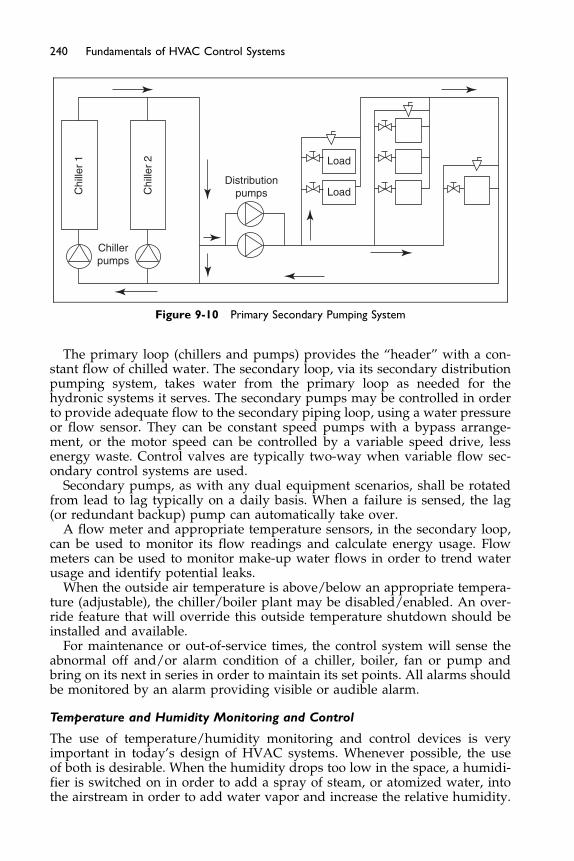
Chi
ller
1
Chi
ller
2
Chillerpumps
Distributionpumps
Load
Load
Figure 9-10 Primary Secondary Pumping System
240 Fundamentals of HVAC Control Systems
The primary loop (chillers and pumps) provides the “header” with a con-stant flow of chilled water. The secondary loop, via its secondary distributionpumping system, takes water from the primary loop as needed for thehydronic systems it serves. The secondary pumps may be controlled in orderto provide adequate flow to the secondary piping loop, using a water pressureor flow sensor. They can be constant speed pumps with a bypass arrange-ment, or the motor speed can be controlled by a variable speed drive, lessenergy waste. Control valves are typically two-way when variable flow sec-ondary control systems are used.
Secondary pumps, as with any dual equipment scenarios, shall be rotatedfrom lead to lag typically on a daily basis. When a failure is sensed, the lag(or redundant backup) pump can automatically take over.
A flow meter and appropriate temperature sensors, in the secondary loop,can be used to monitor its flow readings and calculate energy usage. Flowmeters can be used to monitor make-up water flows in order to trend waterusage and identify potential leaks.
When the outside air temperature is above/below an appropriate tempera-ture (adjustable), the chiller/boiler plant may be disabled/enabled. An over-ride feature that will override this outside temperature shutdown should beinstalled and available.
For maintenance or out-of-service times, the control system will sense theabnormal off and/or alarm condition of a chiller, boiler, fan or pump andbring on its next in series in order to maintain its set points. All alarms shouldbe monitored by an alarm providing visible or audible alarm.
Temperature and Humidity Monitoring and Control
The use of temperature/humidity monitoring and control devices is veryimportant in today’s design of HVAC systems. Whenever possible, the useof both is desirable. When the humidity drops too low in the space, a humidi-fier is switched on in order to add a spray of steam, or atomized water, intothe airstream in order to add water vapor and increase the relative humidity.
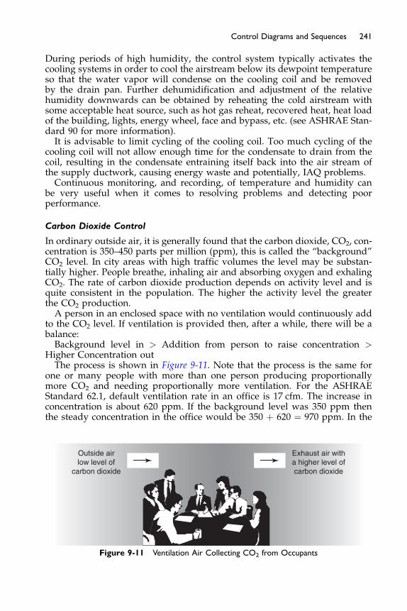
241Control Diagrams and Sequences
During periods of high humidity, the control system typically activates thecooling systems in order to cool the airstream below its dewpoint temperatureso that the water vapor will condense on the cooling coil and be removedby the drain pan. Further dehumidification and adjustment of the relativehumidity downwards can be obtained by reheating the cold airstream withsome acceptable heat source, such as hot gas reheat, recovered heat, heat loadof the building, lights, energy wheel, face and bypass, etc. (see ASHRAE Stan-dard 90 for more information).It is advisable to limit cycling of the cooling coil. Too much cycling of the
cooling coil will not allow enough time for the condensate to drain from thecoil, resulting in the condensate entraining itself back into the air stream ofthe supply ductwork, causing energy waste and potentially, IAQ problems.Continuous monitoring, and recording, of temperature and humidity can
be very useful when it comes to resolving problems and detecting poorperformance.
Carbon Dioxide Control
In ordinary outside air, it is generally found that the carbon dioxide, CO2, con-centration is 350–450 parts per million (ppm), this is called the “background”CO2 level. In city areas with high traffic volumes the level may be substan-tially higher. People breathe, inhaling air and absorbing oxygen and exhalingCO2. The rate of carbon dioxide production depends on activity level and isquite consistent in the population. The higher the activity level the greaterthe CO2 production.A person in an enclosed space with no ventilation would continuously add
to the CO2 level. If ventilation is provided then, after a while, there will be abalance:Background level in > Addition from person to raise concentration >
Higher Concentration outThe process is shown in Figure 9-11. Note that the process is the same for
one or many people with more than one person producing proportionallymore CO2 and needing proportionally more ventilation. For the ASHRAEStandard 62.1, default ventilation rate in an office is 17 cfm. The increase inconcentration is about 620 ppm. If the background level was 350 ppm thenthe steady concentration in the office would be 350 þ 620 ¼ 970 ppm. In the
Outside airlow level of
carbon dioxide
Exhaust air witha higher level ofcarbon dioxide
Figure 9-11 Ventilation Air Collecting CO2 from Occupants
242 Fundamentals of HVAC Control Systems
case of a fully occupied auditorium, the ASHRAE Standard 62.1 default ven-tilation rate is 5 cfm and the increase in concentration is 2,100 ppm providinga steady state level of 350 þ 2,100 ¼ 2,450 ppm.
Note that the added concentration increases in proportion to the number ofpeople for a fixed ventilation rate. Thus halving the population density in anoffice will result in the added CO2 concentration dropping from þ620 ppm toþ310 ppm. Similarly, an increase in ventilation rate for the same occupancywill proportionally drop the added CO2. For example, increasing the officerate from 17 cfm to 20 cfm per person will drop the rate to þ 620 � 17/20 ¼þ527 ppm.
This increase in CO2 concentration can be used to control the ventilationrate. In the high population density auditorium situation, the level of CO2
can be used as a surrogate (equivalent to) for occupant numbers and the ven-tilation rate adjusted to maintain a maximum CO2 concentration. In the lowerdensity office situation Standard 62.1 requires a ventilation rate significantlybased on area per occupant and using CO2 is more complex than we are cov-ering in this course.
More detailed discussions and requirements can be found in ASHRAE Stan-dard 62-2004 and ASTM Standard D6245.
Exhaust Fan Control
Exhaust fan controls are often thermostats or interlock relays specified withlittle thought as to when they are needed to operate. A typical example isthe electrical room provided with a manually set thermostat with a range of60�F to 80�F. It gets set at 60�F and the fan runs continuously for the life ofthe building wasting energy.
Just as for the main system, you should be establishing what service isrequired. This may mean simply linking the exhaust fan in with the main sys-tem. However, for any system that operates out off occupied hours to main-tain temperature or humidity the exhaust fan operation is probably notrequired.
The designer should provide a schedule showing each exhaust fan, its spe-cified design parameters, and its intended control and interlock methodology.Care should be taken to ensure that these exhaust fans do not operate whenthe main HVAC systems are off, unless needed, as this can cause negativepressurization and cause unconditioned outside air to enter the buildingand cause IAQ problems. Where used for conditioning equipment rooms, aroom thermostat should be used to turn the fan on and off to maintain itsexposed temperature set point. In storage rooms, where sensitive materialsare being stored, a thermostat and humidistat may be used in order to operatethe exhaust fans and supplemental dehumidification/humidification equip-ment to maintain the space temperature and humidity requirements.
Toilet exhaust fans are usually interlocked to their respective HVAC systemand its OA damper operation; sometimes the toilet exhaust is supplementallyinterlocked to a light switch. In garages and spaces where hazardous or toxicgases/fumes can gather, exhaust fans are operated continuously, or can becontrolled by a high limit gas/fume-sensor/controller. For chiller plantswhere refrigerants are used, refrigerant gas monitors are set up to operateexhaust fans and/or open dampers/doors when their set points are exceeded.

243Control Diagrams and Sequences
In boiler rooms, exhaust and supply fans can be used in conjunction forexhaust of fumes and to also provide combustion air for the boilers.For medical isolation rooms where harmful bacteria or germs, etc. may
exist, exhaust fan systems, coordinated with supply fan systems, are set upto maintain their individual room pressurization set points, either negativeor positive, and should have a room pressurization monitor and alarm panelinstalled in each room. Visual and audible alarms should be initiated when setpoints are violated, and when the fans fail. In a lot of cases, depending onwhat the intended use of the room is, these exhaust fans may not be switchedoff for any reason, including fire alarm initiation. Isolation room fan sizingand controls should allow for controlling the pressure in the isolation roomin situations when the ambient pressure changes, such as during strongstorms such as hurricanes or tornados.For flammable storage and/or explosion-proof areas, where the fumes are
typically more dangerous and flammable than normal building exhaust, theyare typically controlled using an “explosion-proof” or “non-spark producing”control device. The controls are typically constantly working and respondautomatically to their temperature and gas/fume concentration set points bystaging the exhaust fans on and off. In addition, visual and audible alarmsshould be initiated when crucial or safety set points are exceeded, and/orwhen the fans fail.In almost all cases, exhaust fans need to be specified to be interlocked with
the building fire alarm system to meet all local, state and national codes. Typ-ically, all fans are stopped when the fire alarm system is in alarm, with theexception of engineered smoke control fans and some isolation room fans.
Fume Hood Control
Fume hoods are typically used in laboratories to collect and exhaust fumes.The cross-section of a hood in Figure 9-12 has a vertical sash which can beraised and lowered as necessary. The horizontal air velocity into the hoodis, typically, maintained at a constant velocity of 80–100 fpm whatever thesash height.When the hoods are not operating, the room control is much the same as a
normal occupancy for a variable air volume controlled room. When the hoodsare operating, the control system senses the flows and pressures in the room,hoods, and ducts in and out, and makes adjustments to maintain the temper-ature, humidity, and pressurization of the room. The objectives for control inlaboratory hoods are for the capture and containment of fumes and harmfulgases, to maintain acceptable room pressurization, to maintain acceptabletemperature and humidity set points, and to ventilate the space in order topreserve dilution of contaminants. Many conditions can affect performanceand speed of response from the control system. There are great cost differ-ences between desired levels of control for these systems; the designer needsto know and account for the accuracy and reliability of controls required forthe process.Variable air volume air handling systems are often employed in modern
laboratory and hood systems. A fast and stable control system for the hoods,exhaust fans, supply fans, and all HVAC equipment is suggested. The air-flows required are determined by the highest demand of the minimum
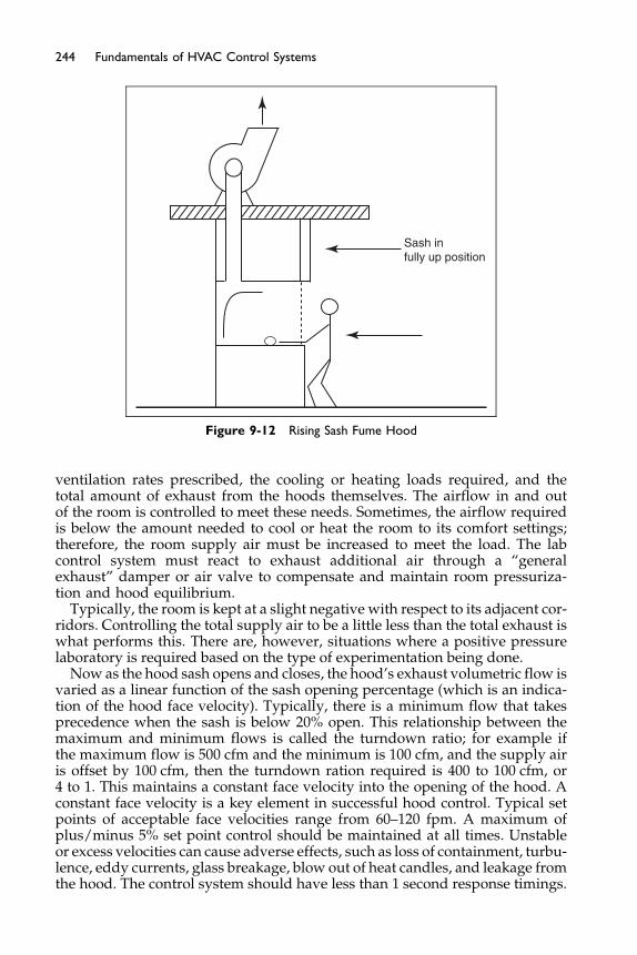
Sash infully up position
Figure 9-12 Rising Sash Fume Hood
244 Fundamentals of HVAC Control Systems
ventilation rates prescribed, the cooling or heating loads required, and thetotal amount of exhaust from the hoods themselves. The airflow in and outof the room is controlled to meet these needs. Sometimes, the airflow requiredis below the amount needed to cool or heat the room to its comfort settings;therefore, the room supply air must be increased to meet the load. The labcontrol system must react to exhaust additional air through a “generalexhaust” damper or air valve to compensate and maintain room pressuriza-tion and hood equilibrium.
Typically, the room is kept at a slight negative with respect to its adjacent cor-ridors. Controlling the total supply air to be a little less than the total exhaust iswhat performs this. There are, however, situations where a positive pressurelaboratory is required based on the type of experimentation being done.
Now as the hood sash opens and closes, the hood’s exhaust volumetric flow isvaried as a linear function of the sash opening percentage (which is an indica-tion of the hood face velocity). Typically, there is a minimum flow that takesprecedence when the sash is below 20% open. This relationship between themaximum and minimum flows is called the turndown ratio; for example ifthe maximum flow is 500 cfm and the minimum is 100 cfm, and the supply airis offset by 100 cfm, then the turndown ration required is 400 to 100 cfm, or4 to 1. This maintains a constant face velocity into the opening of the hood. Aconstant face velocity is a key element in successful hood control. Typical setpoints of acceptable face velocities range from 60–120 fpm. A maximum ofplus/minus 5% set point control should be maintained at all times. Unstableor excess velocities can cause adverse effects, such as loss of containment, turbu-lence, eddy currents, glass breakage, blow out of heat candles, and leakage fromthe hood. The control system should have less than 1 second response timings.

245Control Diagrams and Sequences
There has been much research on control design and implementation.Many other factors such as occupancy in the fume hood areas, usage ofthe hood, cross drafts, sash positions, operator position, diversity of condi-tions, and placement of instrumentation, as well as temperature and humid-ity have a dramatic effect on some aspects of its ultimate control need forsophistication.
Condensate Management and Control
One source of microbial growth is improperly installed and non-functionalcondensate removal from cooling coil drip pans. Controls include drainpan float switches that shut down the fans and/or cooling systems whenthey sense an overfull drain pan. There are pipe sensors that fit in the con-densate piping that sense a ‘too wet’ or ‘too dry’ condition, and stop theirsystems as well as provide alarming that can provide early detection of pro-blems. To detect and alarm carryover in coils, a moisture sensor can beplaced in the ductwork downstream of the cooling coil or humidifier todetect its alarm condition. Provide monitoring of the drain pan overflowand alarm the controller when tripped. To stop the condensate, stop thefan, or stop the DX cooling or close the cooling valve. If available, providea sensor in the condensate pipe exit point so that it can sense the “lack” ofmois-ture removal, which can predict that there is a problem with coil operation orat the drain pan.
Ventilation Monitoring and Control
The accurate and proper monitoring and control of ventilation into thesystem and into the occupied spaces of the building is very important andat the center of today’s most urgent issues in HVAC controls and instrumen-tation. There are many ways to control the outside air entering the system,and the most successful is the direct monitoring with an airflow-monitoringdevice. A velocity-sensing probe is installed in the outside air duct. Depend-ing on the size, and arrangement, of the duct, air-straightening vanes maybe necessary. Follow the manufacturers’ recommendations on mounting,but in general they need to be installed in a piece of duct with at least fivediameters of straight length. The more tubes used, the more accurate anddependable the measurement. In general, one sensing tube per 2 ft2 of ductis a rule of thumb. The velocity needs to be sufficient to create a readableand reliable differential pressure across the velocity tube, so in many casesthe OA duct is downsized. This velocity tube reading is then multipliedby the area of the duct to get airflow in cubic feet per minute (cfm). Thedesigner sets the amount of ventilation airflow in accordance with the localCode, current ASHRAE Standard 62.1, experience, expertise, and her/hisbest judgment. The airflow is monitored and controlled to this set point bymodulating dampers, a fan, a variable speed fan motor, vanes, etc. Somemeans of documentation should be kept of these ventilation airflows in apermanent record.Now that the proper amount of ventilation is being delivered to the supply
fan, it needs to be delivered to the spaces in a proportional, appropriate andeffective manner.
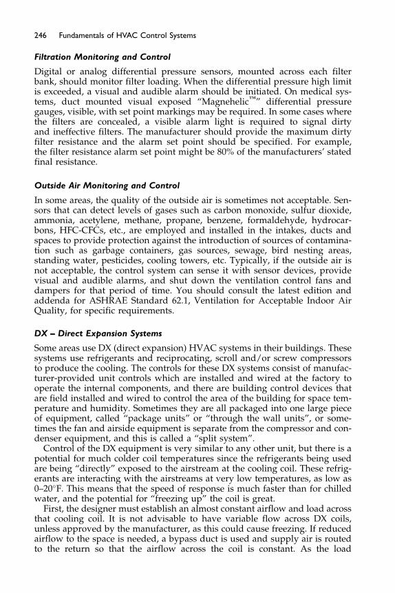
246 Fundamentals of HVAC Control Systems
Filtration Monitoring and Control
Digital or analog differential pressure sensors, mounted across each filterbank, should monitor filter loading. When the differential pressure high limitis exceeded, a visual and audible alarm should be initiated. On medical sys-tems, duct mounted visual exposed “Magnehelic™” differential pressuregauges, visible, with set point markings may be required. In some cases wherethe filters are concealed, a visible alarm light is required to signal dirtyand ineffective filters. The manufacturer should provide the maximum dirtyfilter resistance and the alarm set point should be specified. For example,the filter resistance alarm set point might be 80% of the manufacturers’ statedfinal resistance.
Outside Air Monitoring and Control
In some areas, the quality of the outside air is sometimes not acceptable. Sen-sors that can detect levels of gases such as carbon monoxide, sulfur dioxide,ammonia, acetylene, methane, propane, benzene, formaldehyde, hydrocar-bons, HFC-CFCs, etc., are employed and installed in the intakes, ducts andspaces to provide protection against the introduction of sources of contamina-tion such as garbage containers, gas sources, sewage, bird nesting areas,standing water, pesticides, cooling towers, etc. Typically, if the outside air isnot acceptable, the control system can sense it with sensor devices, providevisual and audible alarms, and shut down the ventilation control fans anddampers for that period of time. You should consult the latest edition andaddenda for ASHRAE Standard 62.1, Ventilation for Acceptable Indoor AirQuality, for specific requirements.
DX – Direct Expansion Systems
Some areas use DX (direct expansion) HVAC systems in their buildings. Thesesystems use refrigerants and reciprocating, scroll and/or screw compressorsto produce the cooling. The controls for these DX systems consist of manufac-turer-provided unit controls which are installed and wired at the factory tooperate the internal components, and there are building control devices thatare field installed and wired to control the area of the building for space tem-perature and humidity. Sometimes they are all packaged into one large pieceof equipment, called “package units” or “through the wall units”, or some-times the fan and airside equipment is separate from the compressor and con-denser equipment, and this is called a “split system”.
Control of the DX equipment is very similar to any other unit, but there is apotential for much colder coil temperatures since the refrigerants being usedare being “directly” exposed to the airstream at the cooling coil. These refrig-erants are interacting with the airstreams at very low temperatures, as low as0–20�F. This means that the speed of response is much faster than for chilledwater, and the potential for “freezing up” the coil is great.
First, the designer must establish an almost constant airflow and load acrossthat cooling coil. It is not advisable to have variable flow across DX coils,unless approved by the manufacturer, as this could cause freezing. If reducedairflow to the space is needed, a bypass duct is used and supply air is routedto the return so that the airflow across the coil is constant. As the load

247Control Diagrams and Sequences
changes, unloading devices and control schemes are used that have a suffi-ciently low minimum capacity. This will allow the unit controls to matchand control to the changing load conditions.When possible, specify a form of recoverable or waste heat for the unit, such
as hot gas bypass/reheat, so that the controls can adjust the temperature andrelative humidity of the leaving air stream. Sometimes this hot gas is also usedto heat the potable water for a building.Controls can be mounted in the control panel on the wall of the mechanical
room or inside the units. The controller should control the stages of DX cool-ing in order to maintain the discharge air temperature at set point, using thestages of cooling and hot gas bypass/reheat where possible. The response ofthe DX cooling effect is very fast, and unloading and multiple staging controlsis necessary to effectively stage the effect. The staging should also have a timedelay between starts, so once a stage is turned completely off, it is typicallynot turned back on for three to five minutes. The supply air temperature setpoint that we are staging to maintain can have some resets embedded insideit, such as being adjusted by the return or outside air temperature.For cold climates, a heating coil in the pre-heat position may be specified to
protect the chilled water coils from freezing in the winter. Alternatively, thecoils must be drained and dried or filled with antifreeze. For hot and humidclimates, a reheating coil after the cooling coil may be required to providereheat after the reduced air delivery required to produce dehumidificationeffects.
Water Source Heat Pumps
A very popular and effective design involves water source heat pumps.A supply of water is continuously pumped around the building with DX unitsconnected to it, as shown in Figure 9-13. Each DX unit has the ability to pumpheat out of the water and into the zone or to cool the space and reject heat tothe circulating water. The system is particularly attractive in buildings withhigh internal cooling loads and perimeter heating loads. The system enablesthe excess heat in some areas to be used in cool areas needing heating, loadtransfer. The DX units operate as above, but their source of energy for heatand cool rejection is water, not the ambient air. The efficiency and capacityof the heat pump is greatly enhanced since it is not restricted by extremeambient conditions. This circulating water source is typically maintainedbetween 60–90�F year round, depending on the environmental and designconditions.The pipe loop is typically connected to a boiler for heat when needed and a
heat rejection evaporative cooling unit or chiller. The source of water for heat-ing and cooling may also come from a lake, or a geothermal well/bore andpump system. Certainly, proper water treatment control is required for eachof these scenarios. The evaporative cooler/cooling tower fans are controlledto maintain the water temperature set point as required. Variable speed fansare frequently used to save energy and improve control performance by mod-ulating the speed of the cooling tower fans to maintain the condenser watertemperature set point of the condenser water. A tower bypass valve can alsobe modulated in order to bypass water around the tower to mix return waterwith its supply water to maintain the condenser water temperature set point.
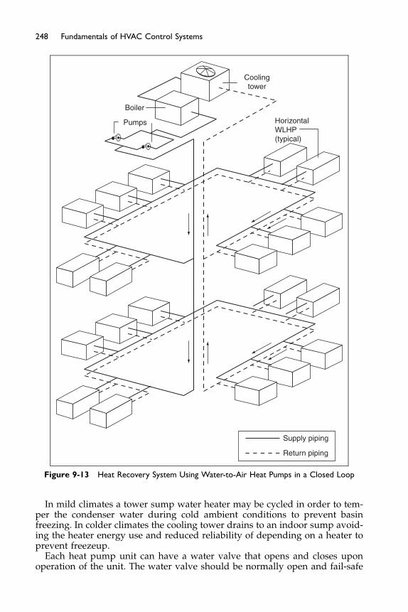
Boiler
Pumps
Coolingtower
HorizontalWLHP(typical)
Supply piping
Return piping
Figure 9-13 Heat Recovery System Using Water-to-Air Heat Pumps in a Closed Loop
248 Fundamentals of HVAC Control Systems
In mild climates a tower sump water heater may be cycled in order to tem-per the condenser water during cold ambient conditions to prevent basinfreezing. In colder climates the cooling tower drains to an indoor sump avoid-ing the heater energy use and reduced reliability of depending on a heater toprevent freezeup.
Each heat pump unit can have a water valve that opens and closes uponoperation of the unit. The water valve should be normally open and fail-safe

249Control Diagrams and Sequences
(open to the coil) if possible. If a water valve is not used, then the water flowsthrough the coil at all times. The pumping system is typically variable speedand provides enough water to the heat pumps as required by a water pressuresensor and control algorithm. If there is variable flow, then a two-way controlvalve should be used (if variable flow is not used, then three-way valves arerequired). A water pressure sensor at/near the end of the piping loop isprovided to control the pump and maintain its pressure set point.If the loop water temperature rises above or below its alarm set point, a vis-
ible and audible alarm shall be initiated, and the heat pumps affected shouldbe stopped until the alarm is resolved. Back up and redundant equipment issuggested to be available to control any major parts of the HVAC&R system,such as pumps, tower fans, heat exchangers, back-up electric heat, etc.
Bibliography
Chen, Steve, Demster, Stanley (1996) Variable Air Volume Systems for EnvironmentalQuality. New York: McGraw-Hill (especially Chapter 5).
Harriman, Lew, Brundrett, Geoffrey W., Kittler, Reinhold (2001) Humidity ControlDesign Guide. Atlanta, GA: ASHRAE (especially Chapter 2).
Persily, Andy (2002) Fall Issue of IAQ Applications. Atlanta, GA: ASHRAE (pp. 8–10).Diamond, Mark (2002) Fall Issue of IAQ Applications. Atlanta, GA: ASHRAE (p. 1).Montgomery, Ross D. (1998) ASHRAE Journal. July. Atlanta, GA: ASHRAE (p. 52).The Holmes Agency, 2001, Mr. Raymond E. Patenaude, P.E., CIAQP. “Proper Controls
for HVAC&R for Indoor Air Quality”, St. Petersburg, FL.ASTM D6245-98(2002) Standard Guide for Using Indoor Carbon Dioxide Concentra-
tions to Evaluate Indoor Air Quality and Ventilation.ASHRAE Standard 134-2005 Graphic Symbols for Heating, Ventilating, Air-Condition-
ing, and Refrigerating Systems.ASHRAE Guideline 13-2000 Specifying Direct Digital Control Systems.
Chapter 10
DDC Introduction toHardware and Software
Contents of Chapter 10
Study Objectives of Chapter 1010.1 Introduction and Input and Output Points
10.2 I/O Point Characteristics 10.3 Control Sequences 10.4 Software Introduction 10.5 Specific Programming System Features and Parameters 10.6 Operator Terminal BibliographyStudy Objectives of Chapter 10
This is the first of three chapters on DDC. DDC stands for direct digital con-trols. It introduces you to the basic hardware and software required to operateDDC controllers and their operator interfaces. The interconnection of thesecontrols is covered in the next chapter while specifications, installation, andcommissioning are covered in the final chapter. After studying this chapter,you should be able to:
Understand the types and performance of physical input and output pointsin DDC systems.
Have an understanding of the range of possibilities in DDC controllers.Know the types of application software available and some relative merits
of each.Be aware of the capabilities available in operator workstations.
10.1 Introduction, and Input and Output Points
DDC are controls operated by digital microprocessors. ‘Digital’ means thatthey operate on a series of pulses, as does the typical PC. In the DDC system,all the inputs and outputs remain; however, they are not processed in the con-trollers, but all control logic is carried out in a computer, based on instructionscalled the “control logic.”
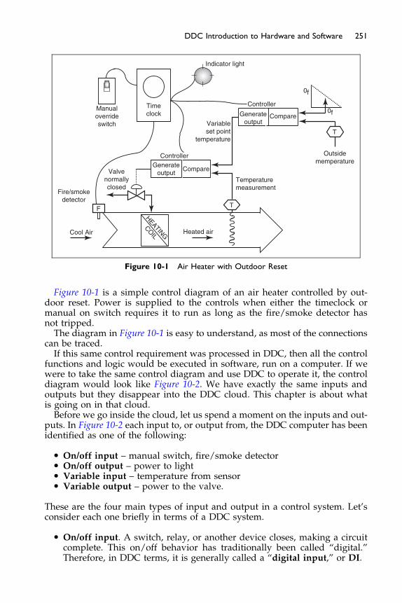
Timeclock
Controller
Compare
ControllerGenerate
outputCompare
Manualoverrideswitch
Valvenormallyclosed
Outsidememperature
Temperaturemeasurement
Variableset point
temperature
Heated airCool Air
Fire/smokedetector
Indicator light
0f
0f
T
T
HEATING
COIL
F
Generateoutput
Figure 10-1 Air Heater with Outdoor Reset
251DDC Introduction to Hardware and Software
Figure 10-1 is a simple control diagram of an air heater controlled by out-door reset. Power is supplied to the controls when either the timeclock ormanual on switch requires it to run as long as the fire/smoke detector hasnot tripped.The diagram in Figure 10-1 is easy to understand, as most of the connections
can be traced.If this same control requirement was processed in DDC, then all the control
functions and logic would be executed in software, run on a computer. If wewere to take the same control diagram and use DDC to operate it, the controldiagram would look like Figure 10-2. We have exactly the same inputs andoutputs but they disappear into the DDC cloud. This chapter is about whatis going on in that cloud.Before we go inside the cloud, let us spend a moment on the inputs and out-
puts. In Figure 10-2 each input to, or output from, the DDC computer has beenidentified as one of the following:
� On/off input – manual switch, fire/smoke detector� On/off output – power to light� Variable input – temperature from sensor� Variable output – power to the valve.
These are the four main types of input and output in a control system. Let’sconsider each one briefly in terms of a DDC system.
� On/off input. A switch, relay, or another device closes, making a circuitcomplete. This on/off behavior has traditionally been called “digital.”Therefore, in DDC terms, it is generally called a “digital input,” or DI.
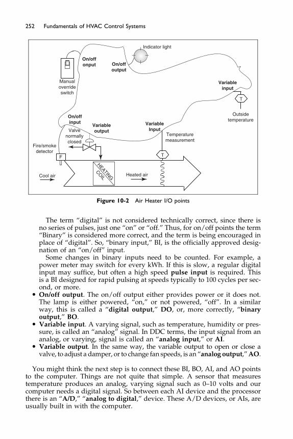
Variableoutput
VariableInput
Variableinput
On/offonput On/off
output
On/offinput
Manualoverrideswitch
Valvenormallyclosed
Temperaturemeasurement
Fire/smokedetector
F
Indicator light
Outsidetemperature
T
T
Heated air
HEATING
COILCool air
Figure 10-2 Air Heater I/O points
252 Fundamentals of HVAC Control Systems
The term “digital” is not considered technically correct, since there isno series of pulses, just one “on” or “off.” Thus, for on/off points the term“Binary” is considered more correct, and the term is being encouraged inplace of “digital”. So, “binary input,” BI, is the officially approved desig-nation of an “on/off” input.
Some changes in binary inputs need to be counted. For example, apower meter may switch for every kWh. If this is slow, a regular digitalinput may suffice, but often a high speed pulse input is required. Thisis a BI designed for rapid pulsing at speeds typically to 100 cycles per sec-ond, or more.
� On/off output. The on/off output either provides power or it does not.The lamp is either powered, “on,” or not powered, “off”. In a similarway, this is called a “digital output,” DO, or, more correctly, “binaryoutput,” BO.
� Variable input. A varying signal, such as temperature, humidity or pres-sure, is called an “analog” signal. In DDC terms, the input signal from ananalog, or varying, signal is called an “analog input,” or AI.
� Variable output. In the same way, the variable output to open or close avalve, to adjust a damper, or to change fan speeds, is an “analog output,”AO.
You might think the next step is to connect these BI, BO, AI, and AO pointsto the computer. Things are not quite that simple. A sensor that measurestemperature produces an analog, varying signal such as 0–10 volts and ourcomputer needs a digital signal. So between each AI device and the processorthere is an “A/D,” “analog to digital,” device. These A/D devices, or AIs, areusually built in with the computer.
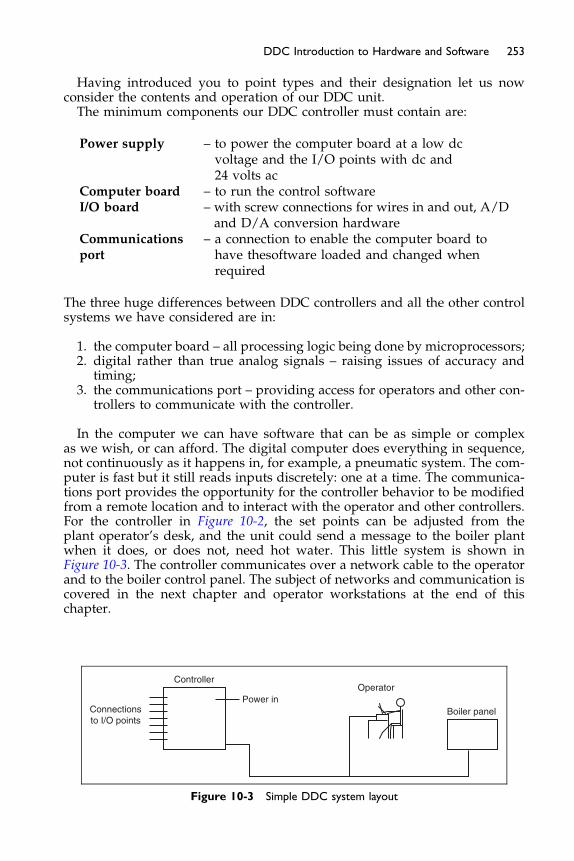
253DDC Introduction to Hardware and Software
Having introduced you to point types and their designation let us nowconsider the contents and operation of our DDC unit.The minimum components our DDC controller must contain are:
Power supply – to power the computer board at a low dcvoltage and the I/O points with dc and24 volts ac
Computer board – to run the control softwareI/O board – with screw connections for wires in and out, A/D
and D/A conversion hardwareCommunicationsport
– a connection to enable the computer board tohave thesoftware loaded and changed whenrequired
The three huge differences between DDC controllers and all the other controlsystems we have considered are in:
1. the computer board – all processing logic being done by microprocessors;2. digital rather than true analog signals – raising issues of accuracy and
timing;3. the communications port – providing access for operators and other con-
trollers to communicate with the controller.
In the computer we can have software that can be as simple or complexas we wish, or can afford. The digital computer does everything in sequence,not continuously as it happens in, for example, a pneumatic system. The com-puter is fast but it still reads inputs discretely: one at a time. The communica-tions port provides the opportunity for the controller behavior to be modifiedfrom a remote location and to interact with the operator and other controllers.For the controller in Figure 10-2, the set points can be adjusted from theplant operator’s desk, and the unit could send a message to the boiler plantwhen it does, or does not, need hot water. This little system is shown inFigure 10-3. The controller communicates over a network cable to the operatorand to the boiler control panel. The subject of networks and communication iscovered in the next chapter and operator workstations at the end of thischapter.
Controller
Power inConnectionsto I/O points
Boiler panel
Operator
Figure 10-3 Simple DDC system layout
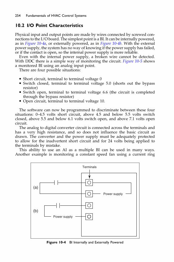
254 Fundamentals of HVAC Control Systems
10.2 I/O Point Characteristics
Physical input and output points are made by wires connected by screwed con-nections to the I/O board. The simplest point is a BI. It can be internally powered,as in Figure 10-4a, or externally powered, as in Figure 10-4b. With the externalpower supply, the system has no way of knowing if the power supply has failed,or if the contact is open, so the internal power supply is more reliable.
Even with the internal power supply, a broken wire cannot be detected.With DDC there is a simple way of monitoring the circuit. Figure 10-5 showsa monitored BI using an analog input point.
There are four possible situations:
� Short circuit, terminal to terminal voltage 0� Switch closed, terminal to terminal voltage 5.0 (shorts out the bypass
resistor)� Switch open, terminal to terminal voltage 6.6 (the circuit is completed
through the bypass resistor)� Open circuit, terminal to terminal voltage 10.
The software can now be programmed to discriminate between these foursituations: 0–4.5 volts short circuit, above 4.5 and below 5.5 volts switchclosed, above 5.5 and below 6.1 volts switch open, and above 7.1 volts opencircuit.
The analog to digital converter circuit is connected across the terminals andhas a very high resistance, and so does not influence the basic circuit asdrawn. The converter and the power supply must be adequately protectedto allow for the inadvertent short circuit and for 24 volts being applied tothe terminals by mistake.
This ability to use an AI as a multiple BI can be used in many ways.Another example is monitoring a constant speed fan using a current ring
Terminals
(a)
(b)
Power supply
Power supply
Figure 10-4 BI Internally and Externally Powered
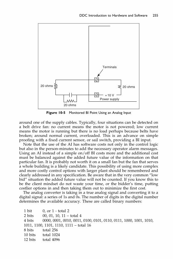
Terminals
20 ohms 20 ohms
20 ohms
+ 10 VPower supply
Figure 10-5 Monitored BI Point Using an Analog Input
255DDC Introduction to Hardware and Software
around one of the supply cables. Typically, four situations can be detected ona belt drive fan: no current means the motor is not powered; low currentmeans the motor is running but there is no load perhaps because belts havebroken; around normal current, overloaded. This is an advance on simpleproofing with a fixed current sensor, or sail switch, providing a BI input.Note that the use of the AI has software costs not only in the control logic
but also in the person-minutes to add the necessary operator alarm messages.Using an AI instead of a simple on/off BI costs more and the additional costmust be balanced against the added future value of the information on thatparticular fan. It is probably not worth it on a small fan but the fan that servesa whole building is a likely candidate. This possibility of using more complexand more costly control options with larger plant should be remembered andclearly addressed in any specification. Be aware that in the very common “lowbid” situation the added future value will not be counted. If you know this tobe the client mindset do not waste your time, or the bidder’s time, puttingcostlier options in and then taking them out to minimize the first cost.The analog converter is taking in a true analog signal and converting it to a
digital signal: a series of 1s and 0s. The number of digits in the digital numberdetermines the available accuracy. These are called binary numbers:
1 bit 0, or 1 - total 22 bits 00, 01, 10, 11 – total 44 bits 0000, 0001, 0010, 0011, 0100, 0101, 0110, 0111, 1000, 1001, 1010,1011, 1100, 1101, 1110, 1111 – total 168 bits total 25610 bits total 102412 bits total 4096

256 Fundamentals of HVAC Control Systems
If the converter is an 8 bit converter it can only pass on a change of 1/256 ofthe incoming signal. For a cool climate, the outside temperature sensor rangemay be -40�F to þ120�F, a range of 160�F. The converter would thus provide adigital signal changing every 160/256 ¼ 0.625�F. This could be quite adequatefor controlling the economizer dampers based on temperature. However,if this signal is also used for calculating the enthalpy of the outside air forcomparison with return air the accuracy is inadequate.
Changing up to a 10 bit converter improves the discrimination to 160/1024¼ 0.16�F which is probably close to the sensor accuracy for normal installa-tions. Moving up to 12 bit 160/4096 ¼ 0.04�F is certainly making the converteras accurate as the sensor. Note that although 12 bit numbers work well forcontrol signals they have severe limitations for accommodating records ofenergy use. It is easy to need to store numbers in the millions when even24 bit numbers (1,048,576) are inadequate for direct storage of accumulatedconsumption. There is a trick to dealing with this challenge. One sets upmore than one register to store the number and when the first register is fullone adds one to the second register and restarts the first register. For a 12bit system the first register nominally stores numbers up to 4096 and thesecond register stores how many 4096s have been accumulated. So if the firstregister is at 2134 and the second at 17 this means the count is 17 � 4096 þ2134 ¼ 71,766.
Note that when you are defining accuracy in DDC systems there are fiveaccuracies which combine to produce the “end-to-end” accuracy. They are:
� medium to sensor� sensor� transmitter� interconnections� A/D converter.
Examples of medium to sensor accuracy being compromised are turbulencein the medium through a flow meter, outside air temperature sensors beinginfluenced by solar radiation, poor mixing of air streams before a mixedair temperature sensor. In each case, the end-to-end accuracy can be severelycompromised by this medium to sensor error. Then there is the sensoraccuracy, what quality was required and what quality was provided? Thetransmitter performance must match the sensor and required range. A trans-mitter designed to provide 0–10 volts with a thermistor over a range of100�F is not going to be very accurate measuring chilled water flow tempera-ture in the range 38–45�F. If wiring is short, it should not significantly influ-ence accuracy. For longer runs it may be better to use a 4–20 ma currentloop rather than the more economical 0–5, or 0–10 volts. Last is A/D conver-sion accuracy, which is discussed above. You are not expected to define eachof these but rather to understand that these points of inaccuracy exist and todefine a required end-to-end accuracy.
If accuracy is an issue, how can you asses the performance of a sensorsystem? By using a competent contractor who has equipment that has beencalibrated by a National Institute of Standards and Technology (NIST) trace-able calibration organization in the USA, the National Physical Laboratory
257DDC Introduction to Hardware and Software
(NPL) in the UK, the Australian Commonwealth Scientific and Research Orga-nization (CSIRO) in Australia or other similar national measurement stan-dards organizations. Note that the HVAC industry serving commercial andinstitutional buildings has, historically, not focused on accuracy of measure-ment and control as the market has demanded adequacy of performanceat lowest bid cost. If you need accuracy, be very selective in your choice ofsupply and installation companies.Having converted the signal from analog to digital, it can then be processed
before being used as an input to the process software. For example, the squarerootmay be takenwhen the incoming signal is velocity pressure so as to providea signal proportional to velocity. The signal can also be smoothed. In an air sys-tem VAV box, the measured velocity signal flutters around so it is common tosmooth the signal. Let us suppose the system is checking the velocity signalevery second and keeping a value called “old signal.” Using a five-secondsmoothing every cycle, the following calculation is made:
ðnew signalþ 4 � old signalÞ=5 ¼ old signal
The “old signal” is the smoothed signal that is used for the controller input.A different input change is the change in set point. This may be due to
changing from unoccupied mode to occupied mode with a correspondingchange in set point or simply the occupant changing the set point. In this sit-uation it is common to include a ramp function. This ramp limits the rate atwhich the control variable can change. The controller is thus steadily drivenin a direction rather than given a shock from which it has to recover.Inputs can also be modified based on a lookup table or formula. Thermis-
tors are non linear and many manufacturers standardize on a specific therm-istor and provide AI points with the lookup table, or algorithm, built in. Thelookup table or formula can also be used to deal with outdoor reset. The infor-mation that the water temperature is to be 70�F at outside temperature of60�F and 190�F at �10�F is all the data needed to set up a lookup table or for-mula to convert from outside temperature to required water temperature.In other words, some mathematics in the software replaces the controller toprovide the outdoor reset signal.Now let us consider outputs AO and BO. The issue of conversion accuracy
is similar on analog outputs as it was on inputs. The difference is that manydriven devices, such as valve and damper actuators, do not react to minutechanges in signal. They need a significant signal change to overcome frictionso 8 bits, giving a nominal 256 increments of change, each of 0.4%, is adequateeven though 10 bit resolution is typically provided.The output power of AO and BO signals is very limited so the signal is fre-
quently used as a control signal not to provide control power. In the case ofpneumatically driven valves and dampers the electric to pneumatic, E/P,transducer will typically be mounted close to the valve to minimize installa-tion cost and maximize response speed. The transducer may be provided withadjustments but it is far better to make all adjustments at the DDC panelwhere changes are specific and can be recorded.This section has briefly introduced you to the inputs and outputs from the
system.

258 Fundamentals of HVAC Control Systems
10.3 Control Sequences
Writing control sequences is neither easy nor quick. Following a clear and log-ical progression significantly increase is the speed and precision. The follow-ing is one step-by-step process. You might also note that large sheets ofpaper are much easier to get started on compared with the standard officenotepad.
Step 1. Make a sketch of the system. Divide the system into subsystems.
The typical systems we have been looking at include mixing dampers,cooling coils, heating coils, and fans.Step 2. Choose each subsystem and identify what is to be controlled and themain process variable.
In an air-handling unit this might be supply temperature and cooling coilchilled-water valve, time and fan running, and duct static pressure andfan speed.
Step 3. Establish the control relationship between the process variable andthe controlled equipment.
In the case of the cooling coil we can have a straight forward PI controlusing duct temperature input, our process variable, and output to theE/P for a pneumatic control valve.If this was an air system, the process variable could be velocity pressure
in which case the process variable could first have been smoothed by tak-ing a rolling average over 5–10 samples and the square root to get velocityand then multiplied by area to get volume. This volume would then beused as controller input. Note that multiplying by the area makes no differ-ence to the controller operation but it is much easier for the operator as acheck on the value when it is in, understandable, useful units.
The control method chosen is often based on the required speed ofresponse, or time constant, of the control loop. Zone temperature controland outdoor reset are both fairly slow control loops. For these a simple pro-portional band control with set with a narrow proportional band will oftenprovide excellent service. For average speed loops such as economizerdampers, heating coils, and cooling coils the PI controller works well. Asmentioned before adding the derivative, PID, makes tuning more difficultand often does not noticeably improve performance.
Step 4. Then list external factors which will affect each control loop.For our cooling coil these may include being interlocked so it cannot runwhen the heating coil is operating, may be disabled at night, will go onand off as the economizer takes on the cooling function, and may bedelayed in opening if the chiller has just been started.For all the control loops there may be overall factors such as running
when occupied, running when unoccupied maintaining occupied tempera-ture, running when unoccupied to prevent excess humidity, running whenunoccupied to maintain setback temperature, maintaining running with firesettings when fire alarm trips, running under Fire Department control.
Step 5. Establish where, and how, the factors in Step 4 are generated.This step is working out how the signals from Step 4 will be generatedand where they will be available. For instance, a delay on opening thechilled-water valve when the chiller has just started will come from
259DDC Introduction to Hardware and Software
the chiller. Since this factor will likely be used by all the chilled-watervalve circuits the chiller should broadcast the information.
Step 6. Work up of the logic.Using the data collected form the previous steps it is now possible towork up the control logic flow for each loop.
Step 7. Work out all the limits which apply, when they are to be applied,and how they are to be applied.
Limits may be absolute limits of temperature, flow, and pressure orlimits on rates of change. For example, in an air-handling unit what is theminimum allowable supply temperature for an alarm, to shut the plantoff. This step typically generates the requirements for safety and alarms.Thus the humidity sensor in a supply duct could provide a signal thatwas used to start overriding the controller when the duct humidity risesabove 85% and sets of an alarm if it rises to 90% relative humidity.
Throughout this process it is important to be very clear about each compo-nent of the system. One way to do this is to consistently use a point namingconvention. Many systems are based on a hierarchy of elements such as:
Type – System – Point – Detail
“Detail” allows for a number of identical points. On a larger system there maywell be a smoke detector in both return duct and supply duct. They are phys-ically the same but need to be differentiated in their name. Some points on anair system AHI might be:
AI AH1 OAT Analog in, sensor, outside air temperatureAI AH1 ST Analog in, sensor, supply air temperatureBO AH1 SF Switch out, supply fan on/offBI AH1 SF Fan proof switchAO AH1 SFS Variable speed, supply fan speed controllerBI AH1 SM 1 Switch, smoke detector 1.
On a site with many buildings, a letter code (ideally an abbreviation) willusually be included before the system, e.g. AI DUF AH1 OAT. If buildingsare on multiple sites, the coding may have a site code and then a buildingcode. The critical issue is to be clear and consistent about your system. Itcan be a well worthwhile exercise trying it out on imaginary systems tomake sure it works in all situations before having the contractor startdetailed drawings. The naming has been introduced starting from realpoints such as analog and digital in and out points. You may wish toextend your convention into standard virtual points such as plant runninghours.If you write these point names on the system diagram and in your speci-
fication it will be easier to keep track of what’s what and where. It will alsobe easier to require the contractor to follow your naming requirements.Finally, have the point names on the items in the field. It is both frustratingand a waste of time for the maintenance staff faced with two identical elec-trical boxes and identical connections and wires inside and not knowingwhich is the temperature sensor and which is the humidity sensor.
260 Fundamentals of HVAC Control Systems
10.4 Software Introduction
We have the IO points and control sequences ready now let us get down toconsidering some software routines to use them.
Let’s consider economizer damper control and how the software logic isworked up. A very simple situation could have the following requirements:
1. When fan is off, damper to be closed (0% open).2. When space occupied, and fan is on, damper is to open at least to mini-
mum position of 20%.3. The damper % opening is to adjust to provide 55�F mixed air when the
temperature is below 67�F using proportional control with 4�F propor-tional band.
We can work up the required logic knowing that proportional control is linearand that, in this case the damper will try to be open 0% at mixed air tempera-ture (MAT) 53�F (55 - 4/2) and 100% at 57�F (55 þ 4/2). Between those pointsthe proportion open will be:
ðmixed air temperature � 53Þð57� 53Þ � 100% ¼ 25� ðMAT� 53Þ
We can work up the logic based on calculating and repeatedly storing thevalue of a variable called “damper output.” Going through the logic, makingchanges to the variable, will provide a value of the damper output to finallybe sent to the damper actuator.
Logic
1. Calculate damper output based on mixed air temperature (MAT): 25 �(MAT-53).
2. If outside air temperature above 67�F change damper output to zero.3. Pass on highest of damper output and minimum damper setting (20%) as
damper output.4. If timeclock at unoccupied set damper output to zero.5. If fan off set damper output to zero.
Does this work? Try it for yourself for a day when the outside temperatureis 89�F, when the fan is on but the timeclock is at unoccupied. Now work outthe situation for a day when it is only 40�F outside with the fan on and thetimeclock is at occupied.
This example is extremely simple. If the logic required integral or enthalpycontrol the logic would have been difficult to work up. In addition the logicis the same for each similar situation. Manufacturers have thus worked upstandard routines for the standard pieces of equipment such as dampersand for standard groups of equipment such as air-handling units, VAV boxes,and heat pumps. However, any variations from standard routines still haveto have their logic worked up and implemented in the system software. Thecontrol software is called application software.
261DDC Introduction to Hardware and Software
Application software falls into two categories: general purpose and applica-tion specific. General-purpose programming languages allow the control sys-tem to perform almost any control function and software may be custom-written for each application. Application-specific software, on the other hand,is preprogrammed for a specific, common HVAC application such ascontrolling a typical air handler. Commercially, application-specific controllersare available where a number of choices are made from a menu of hardwareand software choices. For example, a very common application specific deviceis a residential thermostat. It may, as standard, include the ability to controlone or two stages of heating, one or two stages of cooling, and show the out-side temperature from a remote sensor. In a specific installation this thermostatcould be used with just one stage of heating and one stage of cooling. The extrafunctions are simply not used.Three styles of application programming are commonly used for general-
purpose languages, text, graphical, and ladder-logic.
� Text-based languages. Text-based programming languages resemble stan-dard computer programming languages. In some early DDC systems, theyresembled assembly language programming with four-letter, semi-mnemonic elementary functions, each having several numerical parametersthat only a specially trained programmer could understand. These ratherelementary languages have been replaced by variations on high levelprogramming languages such as BASIC, FORTRAN, C, or Pascal. Specialsubroutines are usually provided for typical HVAC control applications,such as functions to turn equipment on and off with optional time-delays,set point reset tables, minimum/maximum value selection, psychrometricfunctions (such as determining dew point from dry bulb temperature andrelative humidity), optimum start routines, and, most importantly, func-tions to perform PID control loops.
An example of a BASIC-like language is shown in Figure 10-6. The systemwill run this routine every so many seconds. Note the comment statements,C***, that assist the reader in understanding the logic of the program. Theprogram ignores these comments. Also the line numbers have been chosento separate the blocks of logic. Can you work out what is going on?Line 110 checks if the fan is on. If it is on the program skips to line 510. If fan is
off the program sets damper position to 0, closed, and skips to the end of theprogram. If the fan was on the double switch sets temporary value $LOC3to 1 if the temperature is below 63. If temperature above 65 it sets $LOC3 to 0acting as a thermostat with 2 degree dead band. Line 520 sends the programon to the mixed air damper control if $LOC3 is 1. Otherwise the program goesto line 530 and sets the outside air damper to 20% before skipping to the endof the program. Line 610 repetitively calculates the damper position, $LOC1,and line 620 chooses the maximum of $LOC1 and 20 as the required damperpercentage open.Although simple in concept writing effective code is a learned skill. Not
only must one know the exact structure of the code blocks such as IF, LOOP,MAX but also how they can be efficiently and effectively used.
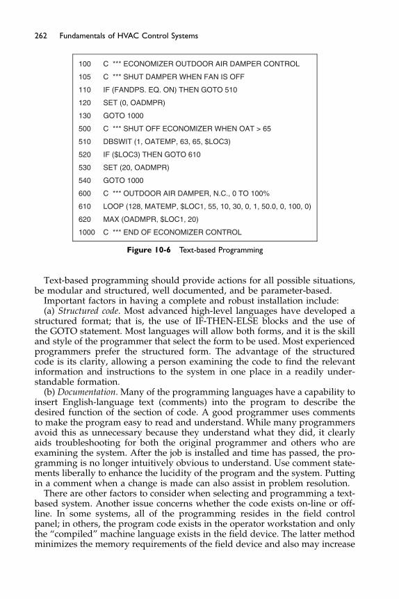
100 C *** ECONOMIZER OUTDOOR AIR DAMPER CONTROL
105 C *** SHUT DAMPER WHEN FAN IS OFF
110 IF (FANDPS. EQ. ON) THEN GOTO 510
120 SET (0, OADMPR)
130 GOTO 1000
500 C *** SHUT OFF ECONOMIZER WHEN OAT > 65
510 DBSWIT (1, OATEMP, 63, 65, $LOC3)
520 IF ($LOC3) THEN GOTO 610
530 SET (20, OADMPR)
540 GOTO 1000
600 C *** OUTDOOR AIR DAMPER, N.C., 0 TO 100%
610 LOOP (128, MATEMP, $LOC1, 55, 10, 30, 0, 1, 50.0, 0, 100, 0)
620 MAX (OADMPR, $LOC1, 20)
1000 C *** END OF ECONOMIZER CONTROL
Figure 10-6 Text-based Programming
262 Fundamentals of HVAC Control Systems
Text-based programming should provide actions for all possible situations,be modular and structured, well documented, and be parameter-based.
Important factors in having a complete and robust installation include:(a) Structured code. Most advanced high-level languages have developed a
structured format; that is, the use of IF-THEN-ELSE blocks and the use ofthe GOTO statement. Most languages will allow both forms, and it is the skilland style of the programmer that select the form to be used. Most experiencedprogrammers prefer the structured form. The advantage of the structuredcode is its clarity, allowing a person examining the code to find the relevantinformation and instructions to the system in one place in a readily under-standable formation.
(b) Documentation. Many of the programming languages have a capability toinsert English-language text (comments) into the program to describe thedesired function of the section of code. A good programmer uses commentsto make the program easy to read and understand. While many programmersavoid this as unnecessary because they understand what they did, it clearlyaids troubleshooting for both the original programmer and others who areexamining the system. After the job is installed and time has passed, the pro-gramming is no longer intuitively obvious to understand. Use comment state-ments liberally to enhance the lucidity of the program and the system. Puttingin a comment when a change is made can also assist in problem resolution.
There are other factors to consider when selecting and programming a text-based system. Another issue concerns whether the code exists on-line or off-line. In some systems, all of the programming resides in the field controlpanel; in others, the program code exists in the operator workstation and onlythe “compiled” machine language exists in the field device. The latter methodminimizes the memory requirements of the field device and also may increase

263DDC Introduction to Hardware and Software
the execution speed of the program by the processor. The program will definewhat conditions or modes will affect the element.Component-style programs typically involve smaller and more numerous
modules. It allows a user or programmer to quickly determine why a systemelement is doing what it is doing and when it should be doing it. It also allowsthe programmer to be thorough and robust, as described above, as he/shewould know that all possibilities are covered. In some systems the paththrough the software can be displayed so that it is easier to trace the logicbeing executed at the current time.Typically, systems are controlled to maintain set point or target values. For
example, the system attempts to maintain the room temperature at a set pointvalue determined by the operator or occupants of the space. While it is easy toinsert these values directly into the program code, it is usually desirable to setthese up as variables so that system operators may reset them in the future.This will allow slight modification and tuning of the system to best matchthe building condition and occupants without the need to reprogram. Whileit is useful to code these constants into the program, do not bury the valuesin the code. It is often best to define the values as variables and set their valuewithin the program but at only one location. A programmer/operator mayeasily alter their values in the future.Much modern control system software allow for “menu-driven” platforms
and configurations. This “fill-in-the-blank” menu software is much easier touse. Almost all of the programming is done for you, all you have to do is fillin some blanks for operational parameters such as set points, schedule times,PID parameters, on and off timers, existing conditions, etc.
� Graphical programming. Graphical programming is based on logic flowcharts. Graphical programs are much easier to “read” and “comprehend”or “visualize” than text-based programs, as can be seen in Figure 10-7. Takea moment and work out the program logic in Figure 10-7. This is the logic:PID Control - if Fan Status is on use Temp, mixed air temperature, to cal-culate required damper position.
OutdoorTemp
Compare(<)
65�F
Off10 30 0 0 0.5
20% 20% 0%
Temp Max Switch Switch
FanStatus
PIDControl
OATDamper
Figure 10-7 Graphical Program
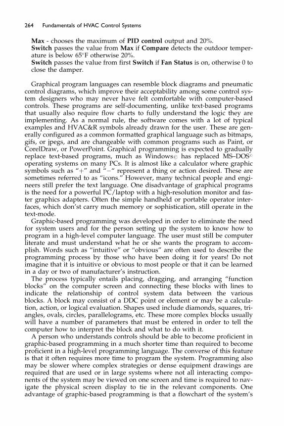
264 Fundamentals of HVAC Control Systems
Max - chooses the maximum of PID control output and 20%.Switch passes the value from Max if Compare detects the outdoor temper-ature is below 65�F otherwise 20%.Switch passes the value from first Switch if Fan Status is on, otherwise 0 toclose the damper.
Graphical program languages can resemble block diagrams and pneumaticcontrol diagrams, which improve their acceptability among some control sys-tem designers who may never have felt comfortable with computer-basedcontrols. These programs are self-documenting, unlike text-based programsthat usually also require flow charts to fully understand the logic they areimplementing. As a normal rule, the software comes with a lot of typicalexamples and HVAC&R symbols already drawn for the user. These are gen-erally configured as a common formatted graphical language such as bitmaps,gifs, or jpegs, and are changeable with common programs such as Paint, orCorelDraw, or PowerPoint. Graphical programming is expected to graduallyreplace text-based programs, much as Windows# has replaced MS–DOS#
operating systems on many PCs. It is almost like a calculator where graphicsymbols such as “þ” and “�“ represent a thing or action desired. These aresometimes referred to as “icons.” However, many technical people and engi-neers still prefer the text language. One disadvantage of graphical programsis the need for a powerful PC/laptop with a high-resolution monitor and fas-ter graphics adapters. Often the simple handheld or portable operator inter-faces, which don’st carry much memory or sophistication, still operate in thetext-mode.
Graphic-based programming was developed in order to eliminate the needfor system users and for the person setting up the system to know how toprogram in a high-level computer language. The user must still be computerliterate and must understand what he or she wants the program to accom-plish. Words such as “intuitive” or “obvious” are often used to describe theprogramming process by those who have been doing it for years! Do notimagine that it is intuitive or obvious to most people or that it can be learnedin a day or two of manufacturer’s instruction.
The process typically entails placing, dragging, and arranging “functionblocks” on the computer screen and connecting these blocks with lines toindicate the relationship of control system data between the variousblocks. A block may consist of a DDC point or element or may be a calcula-tion, action, or logical evaluation. Shapes used include diamonds, squares, tri-angles, ovals, circles, parallelograms, etc. These more complex blocks usuallywill have a number of parameters that must be entered in order to tell thecomputer how to interpret the block and what to do with it.
A person who understands controls should be able to become proficient ingraphic-based programming in a much shorter time than required to becomeproficient in a high-level programming language. The converse of this featureis that it often requires more time to program the system. Programming alsomay be slower where complex strategies or dense equipment drawings arerequired that are used or in large systems where not all interacting compo-nents of the system may be viewed on one screen and time is required to nav-igate the physical screen display to tie in the relevant components. Oneadvantage of graphic-based programming is that a flowchart of the system’s
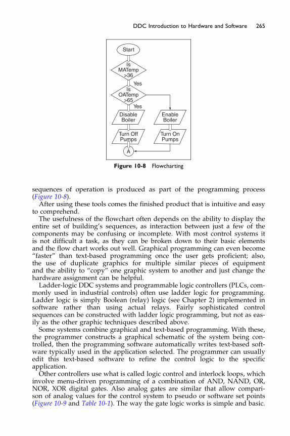
IsMATemp
>36
IsOATemp
>65Yes
Yes
Start
DisableBoiler
EnableBoiler
Turn OffPumps
A
Turn OnPumps
Figure 10-8 Flowcharting
265DDC Introduction to Hardware and Software
sequences of operation is produced as part of the programming process(Figure 10-8).After using these tools comes the finished product that is intuitive and easy
to comprehend.The usefulness of the flowchart often depends on the ability to display the
entire set of building’s sequences, as interaction between just a few of thecomponents may be confusing or incomplete. With most control systems itis not difficult a task, as they can be broken down to their basic elementsand the flow chart works out well. Graphical programming can even become“faster” than text-based programming once the user gets proficient; also,the use of duplicate graphics for multiple similar pieces of equipmentand the ability to “copy” one graphic system to another and just change thehardware assignment can be helpful.Ladder-logic DDC systems and programmable logic controllers (PLCs, com-
monly used in industrial controls) often use ladder logic for programming.Ladder logic is simply Boolean (relay) logic (see Chapter 2) implemented insoftware rather than using actual relays. Fairly sophisticated controlsequences can be constructed with ladder logic programming, but not as eas-ily as the other graphic techniques described above.Some systems combine graphical and text-based programming. With these,
the programmer constructs a graphical schematic of the system being con-trolled, then the programming software automatically writes text-based soft-ware typically used in the application selected. The programmer can usuallyedit this text-based software to refine the control logic to the specificapplication.Other controllers use what is called logic control and interlock loops, which
involve menu-driven programming of a combination of AND, NAND, OR,NOR, XOR digital gates. Also analog gates are similar that allow compari-son of analog values for the control system to pseudo or software set points(Figure 10-9 and Table 10-1). The way the gate logic works is simple and basic.

ANDD1D2 D Out
Logic SymbolD3
D1
D2D3
Figure 10-9 AND gate
Table 10-1 AND Logic
Statement # 1 Statement # 2 Result-and-Gate Response
True True TrueTrue False FalseFalse True FalseFalse False False
266 Fundamentals of HVAC Control Systems
For example, the “AND” and “OR” gates are the most popular and useful.The logic compares two or more true/false inputs, and based on its logic, pro-duces an output of true or false. In the case of the “AND” gate and two state-ments for example, it asks the question if each of the statements are true, i.e.true and true? And the result of a true and a true is a true; otherwise it is afalse result. For example, this “and” logic can be used in the following appli-cation. In an AHU control valve control loop that produces a signal that mod-ulates a control valve for cooling, there can be an “and” gate written thatwould say, if the AHU fan status is on, or true, and the OA damper is open,or true, and the AHU safety devices such as a smoke detector contact or drainpan float switch contact are normal, or true, then the “and” gate can be usedto allow the operation of the control loop; if for some reason 1 or more of thoseinputs go false, then the “and” gate will cause the control loop to stop.
Similarly for an “OR” gate, if any of the statements are true, i.e. a true anda false, a true and a true, or a false and a true, would result in a true result.If both statements were false, then the result would be false. In other words,a true or a true is a true, otherwise false.
This can be shown diagrammatically in many ways as seen below.For the “AND-Gate” example, the definition is that if the stated fact #1
“and” stated fact #2 is true, then the AND gate response is true. All othersresult in a false response. (A “NAND” gate result is the opposite result ofthis.)
For an “OR-Gate” example, the definition is that if the stated fact #1 “or”stated fact #2 is true, then the OR gate response is true. All others result in afalse response. (A “NOR” gate response is the opposite result of this.) For aspecial purpose example called a “XOR-Gate,” the definition is that the resultis true, if and only if, just 1 of the stated facts is true. These simple logic gatescan be used in combination to perform interlocks and complex “relay logic”algorithms. Remember our convention is that if the result of the gate is true,then this disables the desired output, or “open’s” the relay contact, and makesit go to its normal position.
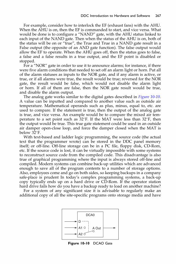
267DDC Introduction to Hardware and Software
For example, consider how to interlock the EF (exhaust fans) with the AHU.When the AHU is on, then the EF is commanded to start, and vice versa. Whatwould be done is to configure a “NAND” gate, with the AHU status linked toeach input of the NAND gate. Then when the status of the AHU is on, both ofthe status will be on or “true”, the True and True in a NAND gate result in aFalse output (the opposite of an AND gate function). The false output wouldallow the EF to operate. When the AHU goes off, then the status goes to false,a false and a false results in a true output, and the EF point is disabled orstopped.For a “NOR” gate in order to use it to announce alarms; for instance, if there
were five alarm conditions that needed to set off an alarm light or horn. Put allof the alarm statuses as inputs to the NOR gate, and if any alarm is active, ortrue, or if all alarms were true, the result would be true; reversed for the NORgate, the result would be false, which would not disable the alarm lightor horn. If all of them are false, then the NOR gate result would be true,and disable the alarm output.The analog gate works similar to the digital gates described in Figure 10-10.
A value can be inputted and compared to another value such as outside airtemperature. Mathematical operands such as plus, minus, equal to, etc. areused to compare. If the statement is true, then the output of the analog gateis true, and vice versa. An example would be to compare the mixed air tem-perature to a set point such as 32�F. If the MAT were less than 32�F, thenthe output would be true. This true gate statement could be used in an outsideair damper open-close loop, and force the damper closed when the MAT isbelow 32�F.With text-based and ladder logic programming, the source code (the actual
text that the programmer wrote) can be stored in the DDC panel memoryitself; or off-line. Off-line storage can be in a PC file, floppy disk, CD-Rom,etc. If the source code is lost, it can be virtually impossible with some systemsto reconstruct source code from the compiled code. This disadvantage is alsotrue of graphical programming where the input is always stored off-line andcompiled. Modern systems can combine back-up utilities which are advancedenough to save all of the program contents to a number of storage options.Also, employees come and go on both sides, so keeping backups in a companysafe-place is prudent In today’s complex programming systems, a back-upcopy typically ends up on a hard drive or CD-Rom. If the operator stationhard drive fails how do you have a backup ready to load on another machine?For a system of any significant size it is advisable to regularly make an
additional copy of all the site-specific programs onto storage media and have
DCA0
D
A1 A Out
A2
Figure 10-10 DCAO Gate

268 Fundamentals of HVAC Control Systems
them stored at a remote site. It only takes one fire in the operator’s room todiscover what good insurance having the programs at a remote locationwould have been!
Application-specific programming is much simpler from the users’s per-spective because the manufacturer already writes the actual control logic.The resultant graphic is much easier to look at than just words on a page. Itis usually presented in a standard format for each type of application specificcontroller. The prewritten programs are generally burned into a chip in themicroprocessor which can be programmed but the program cannot bechanged, PROM, so the programmer may not change them. The user interfaceusually takes the form of question-and-answer (Q&A) or fill-in-the-blank tem-plates. For instance, for a standard single-zone unit control, the user wouldtell the control system: whether the system has cooling or heating capability,or both; whether two-position or modulating control is used; whether the sys-tem has an economizer and what type of high limit lockout switch is used;what set points are to be used; etc. The Q&A interface can also be graphical;the user would bring up a pre-developed schematic of the system on thePC, click on (using the computer’s mouse) the devices that are actually pres-ent in the application, and then enter configuration and set point detailsthrough pull-down menus.
Both general purpose and application-specific programming have advan-tages and disadvantages. General-purpose programs are custom-written toachieve almost any desired control sequence, even the most unusual oruncommon. This provides a great deal of power and flexibility, but it requiresmore knowledge on the part of the programmer and increases programmingtime. It also increases the time required to commission the system becausecustom software is more likely to contain errors, called bugs.
Application-specific software, on the other hand, requires much less timeto program and, because the programs are debugged by the manufacturer,usually requires much less time in the field to commission. However, pre-programmed software is limited to the control logic burned into the chip.Therefore, if a given application does not exactly match the control conceptprogrammed into the controller, some compromises must be made and thesystem may not perform as well as if a custom program was developed usinga general purpose programming language.
To avoid this compromise, sophisticated users can sometimes “fake-out”the preprogrammed software into operating as desired by adjusting set pointsand otherwise using programs in a manner different than originally intendedby the manufacturer (sometimes referred as “work-arounds” or “alternativeuses”). But this defeats the simplicity of application-specific programm-ing, and is not recommended. This can be very difficult to document and sup-port. Several manufacturers have the flexibility of allowing both types ofprogramming; prewritten prewritten programs are provided for commonapplications, but users can also write their own programs using a general-purpose language or “user-defined programming” to connect into the applica-tion program. This methodology of “start with this known reliable baseand add to it if you really need to” is becoming the standard approachin the HVAC controls industry. You will see it again when we discusscommunication protocols for networking in the next chapter.
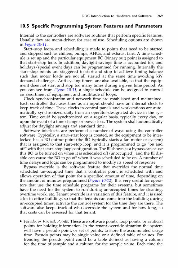
269DDC Introduction to Hardware and Software
10.5 Specific Programming System Features and Parameters
Internal to the controllers are software routines that perform specific features.Usually they are menu-driven for ease of use. Scheduling options are shownin Figure 10-11.Start–stop loops and scheduling is made to points that need to be started
and stopped such as chillers, pumps, AHUs, and exhaust fans. A time sched-ule is set up and the particular equipment BO (binary out) point is assigned tothat start–stop loop. In addition, daylight savings time is accounted for, andholidays/special event days can be programmed for running. Internally thestart–stop points are staggered to start and stop to achieve timing balancesuch that motor loads are not all started at the same time avoiding kWdemand challenges. Anti-cycling timers are also available, so that the equip-ment does not start and stop too many times during a given time period. Asyou can see from Figure 10-11, a single schedule can be assigned to controlan assortment of equipment and multitude of loops.Clock synchronization and network time are established and maintained.
Each controller that uses time as an input should have an internal clock tokeep track of time. These clocks in control panels and workstations are auto-matically synchronized daily from an operator-designated device in the sys-tem. Time could be synchronized on a regular basis, typically every day, orupon the event of a time change or power loss. The system shall automaticallyadjust for daylight savings and standard time.Software interlocks are performed a number of ways using the controller
software. Typically, a start–start loop is created, so the equipment to be inter-locked has a BO output point (the BO typically starts a fan motor or system)that is assigned to that start–stop loop, and it is programmed to go “on andoff” with that start–stop loop configuration. The BI shown as a bypass can causethis BO to be turned on when it is scheduled off (unoccupied), and the BI dis-able can cause the BO to go off when it was scheduled to be on. A number oftime delays and logic can be programmed to modify its speed of response.Bypass override is the software feature that overrides the normal time
scheduled un-occupied time that a controller point is scheduled with andallows operation of that point for a specified amount of time, depending onthe amount of minutes programmed (Figure 10-12). It is very useful for opera-tors that use the time schedule programs for their systems, but sometimeshave the need for the system to run during un-occupied times for cleaning,overtime work, etc. Tenant override is a variation of this feature, and it is useda lot in office buildings so that the tenants can come into the building duringun-occupied times, activate the control system for the time they are there. Thesoftware also keeps track of who overrode the system and for how long, sothat costs can be assessed for that tenant.
� Pseudo, or Virtual, Points. These are software points, loop points, or artificialpoints for holding information. In the tenant override situation the systemwill have a pseudo point, or set of points, to store the accumulated usagetime. Pseudo points may be single value or a defined table of values. Fortrending the pseudo point could be a table defined as having a columnfor the time of sample and a column for the sample value. Each time the
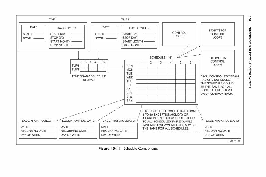
DATE DAY OF WEEK
START
STOP
START DAYSTOP DAYSTART MONTHSTOP MONTH
DATE
1TMP1TMP1
2 3
TEMPORARY SCHEDULE(2 MAX.)
EXCEPTION/HOLIDAY 1
4 5 6
TMP1 TMP2
CONTROLLOOPS
START/STOPCONTROL
LOOPS
THERMOSTATCONTROL
LOOPS
DAY OF WEEK
START
STOP
START DAYSTOP DAYSTART MONTHSTOP MONTH
SCHEDULE (1-8)
SUN1 2 3 4 5 6
MONTUEWEDTHUFRISATSP1SP2SP3
DATERECURRING DATEDAY OF WEEK
EXCEPTION/HOLIDAY 2
DATERECURRING DATEDAY OF WEEK
EXCEPTION/HOLIDAY 3
DATERECURRING DATEDAY OF WEEK
EXCEPTION/HOLIDAY 20
EACH CONTROL PROGRAMHAS ONE SCHEDULE.THE SCHEDULE COULDBE THE SAME FOR ALLCONTROL PROGRAMSOR UNIQUE FOR EACH.
EACH SCHEDULE COULD HAVE FROM1 TO 20 EXCEPTION/HOLIDAY OR1 EXCEPTION HOLIDAY COULD APPLYTO ALL SCHEDULES. FOR EXAMPLE,JANUARY 1 (NEW YEARS DAY) MAY BETHE SAME FOR ALL SCHEDULES. DATE
RECURRING DATEDAY OF WEEK
M17199
Figure 10-11 Schedule Components
270
Fundam
entals
ofHVAC
Contro
lSyste
ms
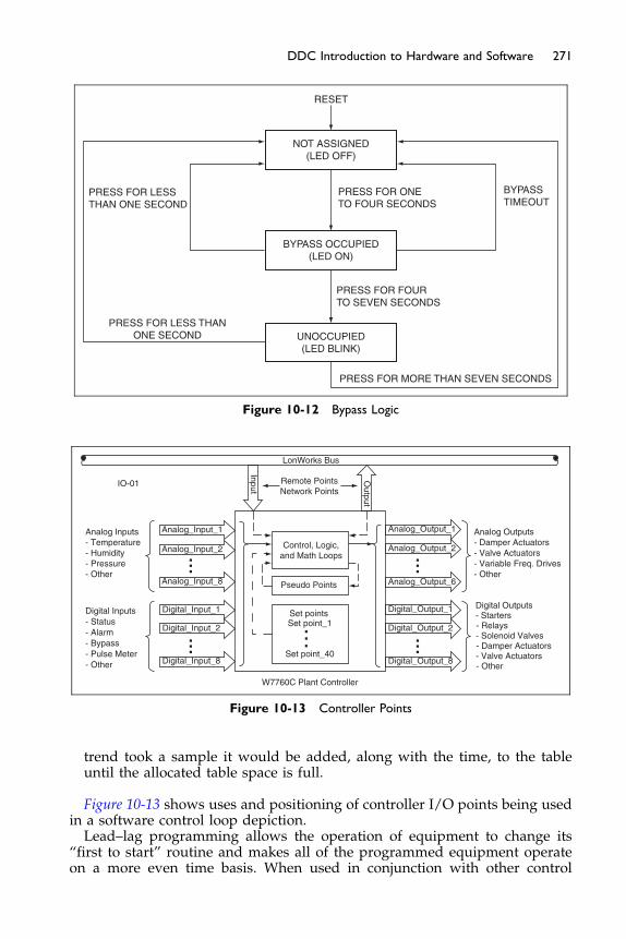
IO-01
Analog Inputs Analog_Input_1
Input
Output
Analog_Input_2
Analog_Input_8
Digital_Input_1
Digital_Input_2
Digital_Input_8
Analog_Output_1
Analog_Output_2
Analog_Output_6
Digital_Output_1
Digital_Output_2
Digital_Output_8
LonWorks Bus
Remote PointsNetwork Points
W7760C Plant Controller
Control, Logic,and Math Loops
Pseudo Points
Set pointsSet point_1
Set point_40
Digital Inputs
- Temperature- Humidity- Pressure- Other
- Status- Alarm- Bypass- Pulse Meter- Other
Analog Outputs
Digital Outputs
- Damper Actuators- Valve Actuators- Variable Freq. Drives- Other
- Starters- Relays- Solenoid Valves- Damper Actuators- Valve Actuators- Other
Figure 10-13 Controller Points
PRESS FOR LESSTHAN ONE SECOND
RESET
NOT ASSIGNED(LED OFF)
PRESS FOR LESS THANONE SECOND
PRESS FOR MORE THAN SEVEN SECONDS
PRESS FOR ONETO FOUR SECONDS
BYPASSTIMEOUT
BYPASS OCCUPIED(LED ON)
UNOCCUPIED(LED BLINK)
PRESS FOR FOURTO SEVEN SECONDS
Figure 10-12 Bypass Logic
271DDC Introduction to Hardware and Software
trend took a sample it would be added, along with the time, to the tableuntil the allocated table space is full.
Figure 10-13 shows uses and positioning of controller I/O points being usedin a software control loop depiction.Lead–lag programming allows the operation of equipment to change its
“first to start” routine and makes all of the programmed equipment operateon a more even time basis. When used in conjunction with other control

Main SensorControl Loop
Loop EPID Output
Seq1 (Heat) Output
Seq2 (Econ) Output
Seq3 (Cool) Output
Auxiliary Output DO
AO/DO
AO/DO
AO/DO
AO/DO
Reset &Recovery
Set pointsControlParam.
Seq.
AI
AI
AI
AI
DISet pointOverride
Set pointAlarms
DI
DI
DI
DIBypass Input
Reset Sensor
Recovery Sensor
Occupancy Sensor
Loop Disable Input
Limit Analog Input
Set point Override 1
Set point Override 4
Figure 10-14 Control Loop
272 Fundamentals of HVAC Control Systems
functions, the lead device comes on first, but if the 2nd or 3rd device isneeded, they can be brought on automatically.
Control loops are used to control small control systems, Figure 10-14. Forinstance, a control loop for discharge air control would use the discharge airtemperature as the main sensor input, and control valve signal as its LoopEPID output. The software that you program into the control loop looks atthe input data, and then makes adjustments to the output value in order tomaintain its set point. The parameters that are programmed by the user intothe control loop are set points, override times, PID values, and action director reverse, set point resets, inputs and outputs, interlocks.
Staging of heating and cooling outputs is very commonplace. Typically, thestages of cooling and heating devices are set up so orderly and even tempera-ture control can be accomplished.
Sequencing of cooling, heating, and economizer functions are programmedinto this feature. When used, it allows for a smooth transition to exist betweenthese modes and does not allow one mode to run while the other mode isworking. For example, it prevents cooling and heating to run at the same time.Remember from other chapters; sometimes during the de-humidification pro-cess, cooling and heating processes occur simultaneously. There is a lot writ-ten about PID loops in previous chapters, but by using DDC systems, thisprogramming is primary in its functionality. Figure 10-15 demonstrate theactions and reactions of the PI programming options frequently used inDDC systems. The “D” of PID is purposely left out as it is rarely used in thecontrol of HVAC processes.
Using a PI routine, Figure 10-15, the proportional error is smoothed out overtime, and the integral time helps get closer to set point as time goes by.
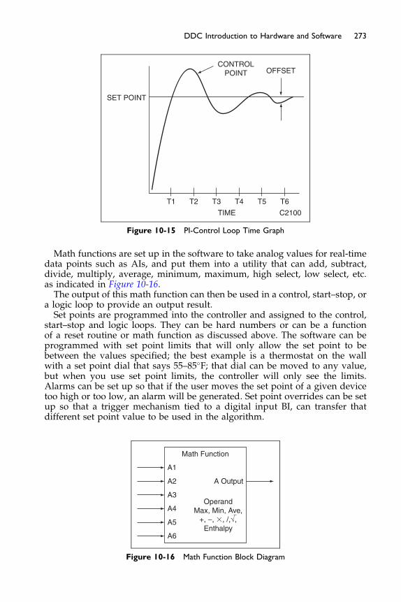
T1 T2 T3 T4 T5
TIME C2100
SET POINT
CONTROLPOINT OFFSET
T6
Figure 10-15 PI-Control Loop Time Graph
273DDC Introduction to Hardware and Software
Math functions are set up in the software to take analog values for real-timedata points such as AIs, and put them into a utility that can add, subtract,divide, multiply, average, minimum, maximum, high select, low select, etc.as indicated in Figure 10-16.The output of this math function can then be used in a control, start–stop, or
a logic loop to provide an output result.Set points are programmed into the controller and assigned to the control,
start–stop and logic loops. They can be hard numbers or can be a functionof a reset routine or math function as discussed above. The software can beprogrammed with set point limits that will only allow the set point to bebetween the values specified; the best example is a thermostat on the wallwith a set point dial that says 55–85�F; that dial can be moved to any value,but when you use set point limits, the controller will only see the limits.Alarms can be set up so that if the user moves the set point of a given devicetoo high or too low, an alarm will be generated. Set point overrides can be setup so that a trigger mechanism tied to a digital input BI, can transfer thatdifferent set point value to be used in the algorithm.
Math Function
A1
A Output
OperandMax, Min, Ave,
+, −, �, /,√,Enthalpy
A2
A3
A4
A5
A6
Figure 10-16 Math Function Block Diagram
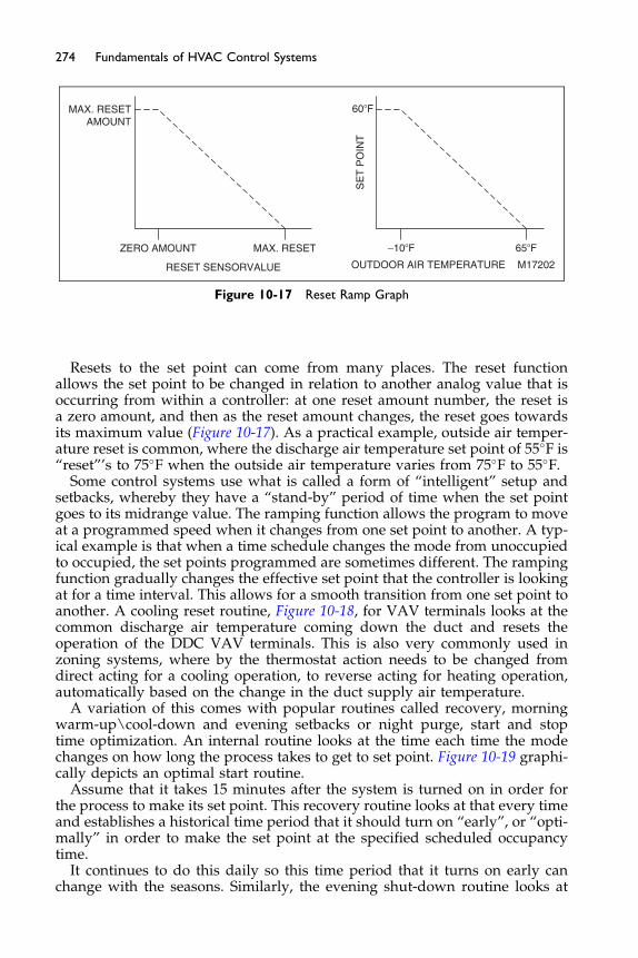
ZERO AMOUNT
RESET SENSORVALUE OUTDOOR AIR TEMPERATURE
SE
T P
OIN
T
60�F
−10�F 65�F
M17202
MAX. RESETAMOUNT
MAX. RESET
Figure 10-17 Reset Ramp Graph
274 Fundamentals of HVAC Control Systems
Resets to the set point can come from many places. The reset functionallows the set point to be changed in relation to another analog value that isoccurring from within a controller: at one reset amount number, the reset isa zero amount, and then as the reset amount changes, the reset goes towardsits maximum value (Figure 10-17). As a practical example, outside air temper-ature reset is common, where the discharge air temperature set point of 55�F is“reset”’s to 75�F when the outside air temperature varies from 75�F to 55�F.
Some control systems use what is called a form of “intelligent” setup andsetbacks, whereby they have a “stand-by” period of time when the set pointgoes to its midrange value. The ramping function allows the program to moveat a programmed speed when it changes from one set point to another. A typ-ical example is that when a time schedule changes the mode from unoccupiedto occupied, the set points programmed are sometimes different. The rampingfunction gradually changes the effective set point that the controller is lookingat for a time interval. This allows for a smooth transition from one set point toanother. A cooling reset routine, Figure 10-18, for VAV terminals looks at thecommon discharge air temperature coming down the duct and resets theoperation of the DDC VAV terminals. This is also very commonly used inzoning systems, where by the thermostat action needs to be changed fromdirect acting for a cooling operation, to reverse acting for heating operation,automatically based on the change in the duct supply air temperature.
A variation of this comes with popular routines called recovery, morningwarm-up\cool-down and evening setbacks or night purge, start and stoptime optimization. An internal routine looks at the time each time the modechanges on how long the process takes to get to set point. Figure 10-19 graphi-cally depicts an optimal start routine.
Assume that it takes 15 minutes after the system is turned on in order forthe process to make its set point. This recovery routine looks at that every timeand establishes a historical time period that it should turn on “early”, or “opti-mally” in order to make the set point at the specified scheduled occupancytime.
It continues to do this daily so this time period that it turns on early canchange with the seasons. Similarly, the evening shut-down routine looks at
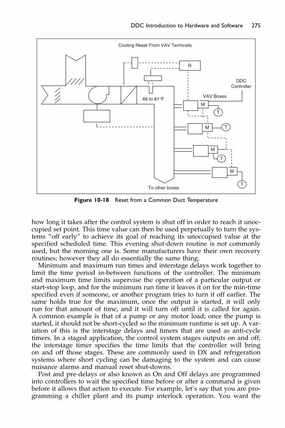
R
M
M
M
M
T
T
T
T
DDCController
To other boxes
Cooling Reset From VAV Terminals
VAV Boxes66 to 81°F
Figure 10-18 Reset from a Common Duct Temperature
275DDC Introduction to Hardware and Software
how long it takes after the control system is shut off in order to reach it unoc-cupied set point. This time value can then be used perpetually to turn the sys-tems “off early” to achieve its goal of reaching its unoccupied value at thespecified scheduled time. This evening shut-down routine is not commonlyused, but the morning one is. Some manufacturers have their own recoveryroutines; however they all do essentially the same thing.Minimum and maximum run times and interstage delays work together to
limit the time period in-between functions of the controller. The minimumand maximum time limits supervise the operation of a particular output orstart-stop loop, and for the minimum run time it leaves it on for the min-timespecified even if someone, or another program tries to turn it off earlier. Thesame holds true for the maximum, once the output is started, it will onlyrun for that amount of time, and it will turn off until it is called for again.A common example is that of a pump or any motor load; once the pump isstarted, it should not be short-cycled so the minimum runtime is set up. A var-iation of this is the interstage delays and timers that are used as anti-cycletimers. In a staged application, the control system stages outputs on and off;the interstage timer specifies the time limits that the controller will bringon and off those stages. These are commonly used in DX and refrigerationsystems where short cycling can be damaging to the system and can causenuisance alarms and manual reset shut-downs.Post and pre-delays or also known as On and Off delays are programmed
into controllers to wait the specified time before or after a command is givenbefore it allows that action to execute. For example, let’s say that you are pro-gramming a chiller plant and its pump interlock operation. You want the
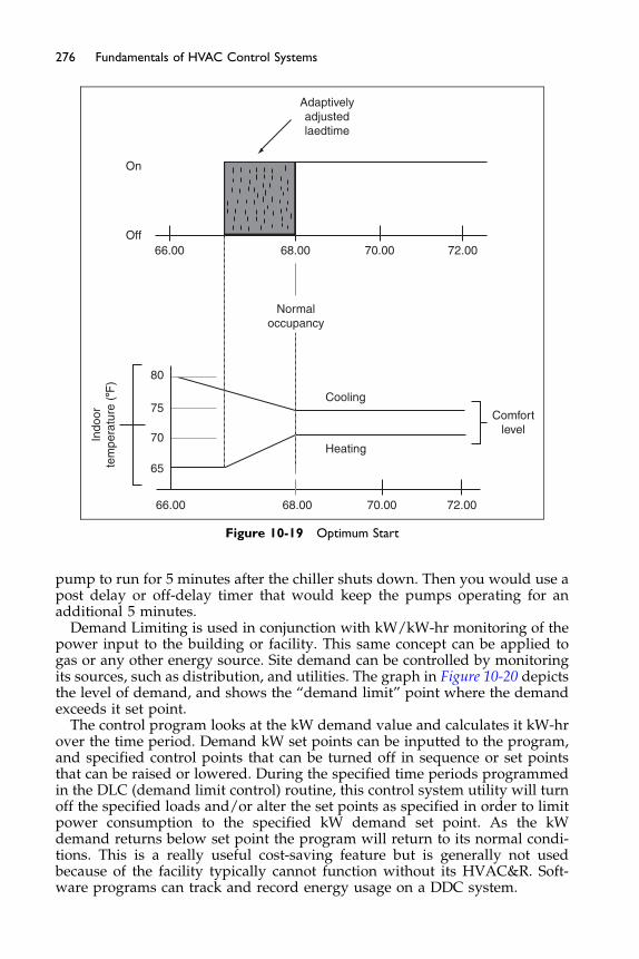
On
Adaptivelyadjustedlaedtime
Off66.00 68.00 70.00
Cooling
Indo
orte
mpe
ratu
re (8F
) 80
75
70
65
66.00 68.00 70.00 72.00
Comfortlevel
Heating
72.00
Normaloccupancy
Figure 10-19 Optimum Start
276 Fundamentals of HVAC Control Systems
pump to run for 5 minutes after the chiller shuts down. Then you would use apost delay or off-delay timer that would keep the pumps operating for anadditional 5 minutes.
Demand Limiting is used in conjunction with kW/kW-hr monitoring of thepower input to the building or facility. This same concept can be applied togas or any other energy source. Site demand can be controlled by monitoringits sources, such as distribution, and utilities. The graph in Figure 10-20 depictsthe level of demand, and shows the “demand limit” point where the demandexceeds it set point.
The control program looks at the kW demand value and calculates it kW-hrover the time period. Demand kW set points can be inputted to the program,and specified control points that can be turned off in sequence or set pointsthat can be raised or lowered. During the specified time periods programmedin the DLC (demand limit control) routine, this control system utility will turnoff the specified loads and/or alter the set points as specified in order to limitpower consumption to the specified kW demand set point. As the kWdemand returns below set point the program will return to its normal condi-tions. This is a really useful cost-saving feature but is generally not usedbecause of the facility typically cannot function without its HVAC&R. Soft-ware programs can track and record energy usage on a DDC system.

3000
2000
KW
Dem
and
Limit
MID MID2 4 6 8 10 2 4 6 8 1012Monday, July 1
Noon
Figure 10-20 Power Demand Graph
277DDC Introduction to Hardware and Software
Outside air temperature, relative humidity and CO2 conditions are moni-tored and can globally be assigned to control functions and make adjustmentsthat control system operation. Large chiller or boiler operations can beadjusted for its seasonal impacts. Also, outside air ventilation can be adjusted.Other building systems can provide input signals to the DDC system for
information and action. The fire alarm system can send the DDC systeman input that it is in alarm, and the DDC system can shut off the air handlingsystems in concert with the fire alarm system. Most DDC systems are notlisted/approved for the primary shut-down of the air handling equipment(because fire alarm and life safety NFPA standards/codes do not allow forit), but can certainly be used as a secondary source of shut-down. Security sys-tems can communicate with the DDC systems and let it know when peopleare in the building; this feature is sometimes used to start or stop theHVAC&R systems on actual occupancy sensing and after-hours overridesituations. Lighting control systems can communicate with the DDC systemand talk to each other about occupancy strategies and optimization.Trend logging, Figure 10-21, is considered by many to be one of the most
important features of DDC systems. This term refers to the ability of the systemto store the values of input and output points on either a time-of-day basis(such as every 30 seconds) or a change-of-state basis (such as every time abinary point turns from on to off or vice versa, or every time an analog pointchanges value by more than a preset range). With many early systems, trenddata were stored on the disks of the operator workstation computer. However,most systems now store trend data in the protected DDC panel memory or in adedicated trend storage device connected to the communications network.Trend data can be used to diagnose program bugs and to optimize the con-
trol system in general. With standard pneumatic or electronic controls, pro-blems are often difficult to diagnose unless someone actually observes thefault in real-time, which is often a matter of luck. Trending removes this
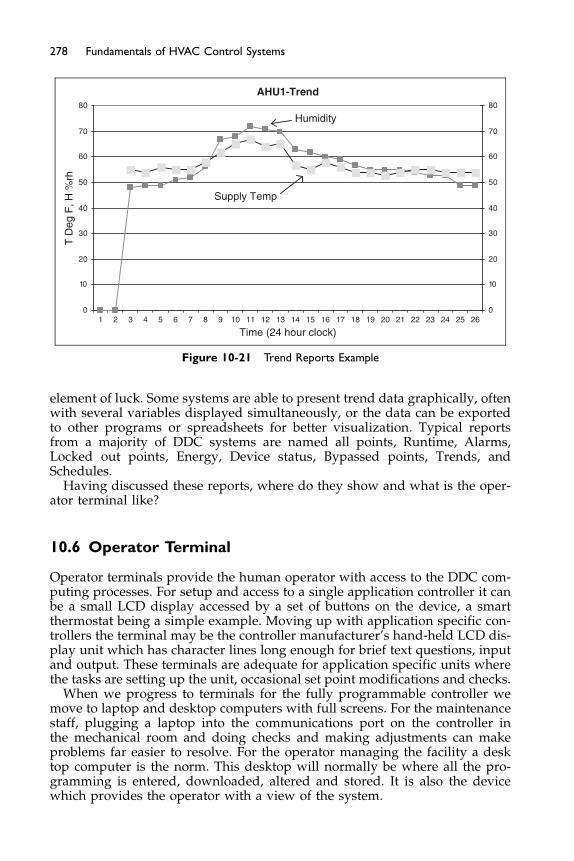
0
10
20
30
40
50
60
70
80
0
10
20
30
40
50
60
70
80
Time (24 hour clock)
T D
eg F
, H %
rh
AHU1-Trend
Humidity
Supply Temp
1 2 3 4 5 6 7 8 9 10 11 12 13 14 15 16 17 18 19 20 21 22 23 24 25 26
Figure 10-21 Trend Reports Example
278 Fundamentals of HVAC Control Systems
element of luck. Some systems are able to present trend data graphically, oftenwith several variables displayed simultaneously, or the data can be exportedto other programs or spreadsheets for better visualization. Typical reportsfrom a majority of DDC systems are named all points, Runtime, Alarms,Locked out points, Energy, Device status, Bypassed points, Trends, andSchedules.
Having discussed these reports, where do they show and what is the oper-ator terminal like?
10.6 Operator Terminal
Operator terminals provide the human operator with access to the DDC com-puting processes. For setup and access to a single application controller it canbe a small LCD display accessed by a set of buttons on the device, a smartthermostat being a simple example. Moving up with application specific con-trollers the terminal may be the controller manufacturer’s hand-held LCD dis-play unit which has character lines long enough for brief text questions, inputand output. These terminals are adequate for application specific units wherethe tasks are setting up the unit, occasional set point modifications and checks.
When we progress to terminals for the fully programmable controller wemove to laptop and desktop computers with full screens. For the maintenancestaff, plugging a laptop into the communications port on the controller inthe mechanical room and doing checks and making adjustments can makeproblems far easier to resolve. For the operator managing the facility a desktop computer is the norm. This desktop will normally be where all the pro-gramming is entered, downloaded, altered and stored. It is also the devicewhich provides the operator with a view of the system.
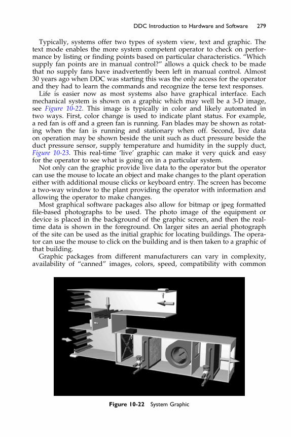
279DDC Introduction to Hardware and Software
Typically, systems offer two types of system view, text and graphic. Thetext mode enables the more system competent operator to check on perfor-mance by listing or finding points based on particular characteristics. “Whichsupply fan points are in manual control?” allows a quick check to be madethat no supply fans have inadvertently been left in manual control. Almost30 years ago when DDC was starting this was the only access for the operatorand they had to learn the commands and recognize the terse text responses.Life is easier now as most systems also have graphical interface. Each
mechanical system is shown on a graphic which may well be a 3-D image,see Figure 10-22. This image is typically in color and likely automated intwo ways. First, color change is used to indicate plant status. For example,a red fan is off and a green fan is running. Fan blades may be shown as rotat-ing when the fan is running and stationary when off. Second, live dataon operation may be shown beside the unit such as duct pressure beside theduct pressure sensor, supply temperature and humidity in the supply duct,Figure 10-23. This real-time ‘live’ graphic can make it very quick and easyfor the operator to see what is going on in a particular system.Not only can the graphic provide live data to the operator but the operator
can use the mouse to locate an object and make changes to the plant operationeither with additional mouse clicks or keyboard entry. The screen has becomea two-way window to the plant providing the operator with information andallowing the operator to make changes.Most graphical software packages also allow for bitmap or jpeg formatted
file-based photographs to be used. The photo image of the equipment ordevice is placed in the background of the graphic screen, and then the real-time data is shown in the foreground. On larger sites an aerial photographof the site can be used as the initial graphic for locating buildings. The opera-tor can use the mouse to click on the building and is then taken to a graphic ofthat building.Graphic packages from different manufacturers can vary in complexity,
availability of “canned” images, colors, speed, compatibility with common
Figure 10-22 System Graphic
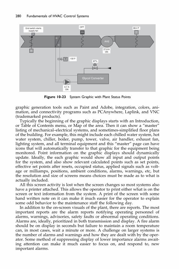
TFR
T
AH2
Glycol Converter
M
H
C
End switch startssupply fan
OFF 68.4 F
132 F87%
27.8 AON
6.7 AON
Figure 10-23 System Graphic with Plant Status Points
280 Fundamentals of HVAC Control Systems
graphic generation tools such as Paint and Adobe, integration, colors, ani-mation, and connectivity programs such as PCAnywhere, Laplink, and VNC(trademarked products).
Typically the beginning of the graphic displays starts with an Introduction,or Table of Contents menu, or Map of the area. Then it can show a “master”listing of mechanical–electrical systems, and sometimes-simplified floor plansof the building. For example, this might include each chilled water system, hotwater system, chiller, boiler, pump, tower, valve, air handler, exhaust fan,lighting system, and all terminal equipment and this “master” page can haveicons that will automatically transfer to that graphic for the equipment beingmonitored. Point information on the graphic displays should dynamicallyupdate. Ideally, the each graphic would show all input and output pointsfor the system, and also show relevant calculated points such as set points,effective set points after resets, occupied status, applied signals such as volt-age or milliamps, positions, ambient conditions, alarms, warnings, etc, butthe resolution and size of screens means choices must be made as to what isactually included.
All this screen activity is lost when the screen changes so most systems alsohave a printer attached. This allows the operator to print either what is on thescreen or text information from the system. A print of the screen with somehand written note on it can make it much easier for the operator to explainsome odd behavior to the maintenance staff the following day.
In addition to the on-screen visuals of the plant, there are reports. The mostimportant reports are the alarm reports notifying operating personnel ofalarms, warnings, advisories, safety faults or abnormal operating conditions.Alarms are, ideally, prioritized in both transmission and display. A fire alarmshould be on display in seconds but failure to maintain a room temperaturecan, in most cases, wait a minute or more. A challenge on larger systems isthe number of alarms and warnings and how they are dealt with by the oper-ator. Some method of suppressing display of lower importance alarms await-ing attention can make it much easier to focus on, and respond to, newimportant alarms.
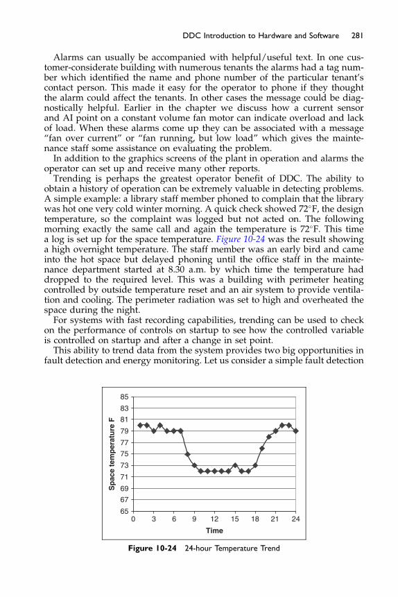
281DDC Introduction to Hardware and Software
Alarms can usually be accompanied with helpful/useful text. In one cus-tomer-considerate building with numerous tenants the alarms had a tag num-ber which identified the name and phone number of the particular tenant’scontact person. This made it easy for the operator to phone if they thoughtthe alarm could affect the tenants. In other cases the message could be diag-nostically helpful. Earlier in the chapter we discuss how a current sensorand AI point on a constant volume fan motor can indicate overload and lackof load. When these alarms come up they can be associated with a message“fan over current” or “fan running, but low load” which gives the mainte-nance staff some assistance on evaluating the problem.In addition to the graphics screens of the plant in operation and alarms the
operator can set up and receive many other reports.Trending is perhaps the greatest operator benefit of DDC. The ability to
obtain a history of operation can be extremely valuable in detecting problems.A simple example: a library staff member phoned to complain that the librarywas hot one very cold winter morning. A quick check showed 72�F, the designtemperature, so the complaint was logged but not acted on. The followingmorning exactly the same call and again the temperature is 72�F. This timea log is set up for the space temperature. Figure 10-24 was the result showinga high overnight temperature. The staff member was an early bird and cameinto the hot space but delayed phoning until the office staff in the mainte-nance department started at 8.30 a.m. by which time the temperature haddropped to the required level. This was a building with perimeter heatingcontrolled by outside temperature reset and an air system to provide ventila-tion and cooling. The perimeter radiation was set to high and overheated thespace during the night.For systems with fast recording capabilities, trending can be used to check
on the performance of controls on startup to see how the controlled variableis controlled on startup and after a change in set point.This ability to trend data from the system provides two big opportunities in
fault detection and energy monitoring. Let us consider a simple fault detection
650 3 6 9 12 15 18 21 24
67
69
71
73
75
77
79
81
83
85
Time
Sp
ace
tem
per
atu
re F
Figure 10-24 24-hour Temperature Trend
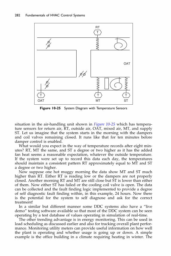
RT
OAT MT ST
T
T TT
OAT
Figure 10-25 System Diagram with Temperature Sensors
282 Fundamentals of HVAC Control Systems
situation in the air-handling unit shown in Figure 10-25 which has tempera-ture sensors for return air, RT, outside air, OAT, mixed air, MT, and supplyST. Let us imagine that the system starts in the morning with the dampersand coil valves remaining closed. It runs like that for ten minutes beforedamper control is enabled.
What would you expect in the way of temperature records after eight min-utes? RT, MT the same, and ST a degree or two higher as it has the addedfan heat seems a reasonable expectation, whatever the outside temperature.If the system were set up to record this data each day, the temperaturesshould maintain a consistent pattern RT approximately equal to MT and STa degree or two higher.
Now suppose one hot muggy morning the data show MT and ST muchhigher than RT. Either RT is reading low or the dampers are not properlyclosed. Another morning RT and MT are still close but ST is lower than eitherof them. Now either ST has failed or the cooling coil valve is open. The datacan be collected and the fault finding logic implemented to provide a degreeof self diagnostic fault finding within, in this example, 24 hours. Now thereis the potential for the system to self diagnose and ask for the correcttreatment!
In a similar but different manner some DDC systems also have a “livedemo” testing software available so that most of the DDC system can be seenoperating by a test database of values operating in simulation of real-time.
The other trending advantage is in energy monitoring. This can be used inload scheduling as discussed earlier and also for tracking overall plant perfor-mance. Monitoring utility meters can provide useful information on how wellthe plant is operating and whether usage is going up or down. A simpleexample is the office building in a climate requiring heating in winter. The
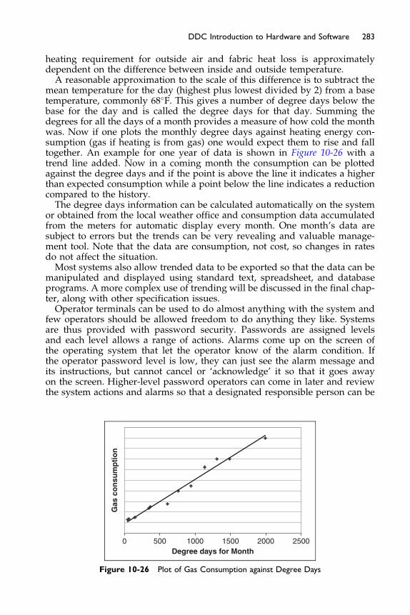
283DDC Introduction to Hardware and Software
heating requirement for outside air and fabric heat loss is approximatelydependent on the difference between inside and outside temperature.A reasonable approximation to the scale of this difference is to subtract the
mean temperature for the day (highest plus lowest divided by 2) from a basetemperature, commonly 68�F. This gives a number of degree days below thebase for the day and is called the degree days for that day. Summing thedegrees for all the days of a month provides a measure of how cold the monthwas. Now if one plots the monthly degree days against heating energy con-sumption (gas if heating is from gas) one would expect them to rise and falltogether. An example for one year of data is shown in Figure 10-26 with atrend line added. Now in a coming month the consumption can be plottedagainst the degree days and if the point is above the line it indicates a higherthan expected consumption while a point below the line indicates a reductioncompared to the history.The degree days information can be calculated automatically on the system
or obtained from the local weather office and consumption data accumulatedfrom the meters for automatic display every month. One month’s data aresubject to errors but the trends can be very revealing and valuable manage-ment tool. Note that the data are consumption, not cost, so changes in ratesdo not affect the situation.Most systems also allow trended data to be exported so that the data can be
manipulated and displayed using standard text, spreadsheet, and databaseprograms. A more complex use of trending will be discussed in the final chap-ter, along with other specification issues.Operator terminals can be used to do almost anything with the system and
few operators should be allowed freedom to do anything they like. Systemsare thus provided with password security. Passwords are assigned levelsand each level allows a range of actions. Alarms come up on the screen ofthe operating system that let the operator know of the alarm condition. Ifthe operator password level is low, they can just see the alarm message andits instructions, but cannot cancel or ‘acknowledge’ it so that it goes awayon the screen. Higher-level password operators can come in later and reviewthe system actions and alarms so that a designated responsible person can be
Degree days for Month
Gas
co
nsu
mp
tio
n
0 500 1500 2000 25001000
Figure 10-26 Plot of Gas Consumption against Degree Days
284 Fundamentals of HVAC Control Systems
made aware of them. This feature is important so that alarms are dealt withand not ignored.
Most systems also record the operators as they log on and log off providinga history. This can be particularly valuable in a large operation where onewants to find out which particular staff was logged on last evening.
The control system software and front-end computer can also providemaintenance scheduling. It can be manufacturer provided or third-partyadd-on software. Programs can be provided that will print maintenance workorders and follow-up reports on a regular basis or after a certain number ofequipment run-hours, alarm triggers or timed routines, thereby allowingimproved maintenance and performance of the equipment. ASHRAE Stan-dard 180 – Standard Practice for Inspection and Maintenance of HVAC Sys-tems – is making several recommendations on using DDC systems formaintenance and operations of a typical building. Typical examples are filterchanging, coil cleaning, and routine lubrication of motors at run time or timeintervals are just a few examples of how proper care and maintenance ofHVAC&R systems can improve energy efficiency and functionality.
Help screens and training resources are available from most DDC systems.The software documentation should be on paper but also available from thePC in software so that the operator can access it regularly. These help andtraining venues should also be updated periodically thru access to the manu-facturers web page as automatic downloads.
This chapter has covered points, application programs, and operator term-inals. The next chapter will cover how systems are networked together andthe protocols that facilitate interoperability.
Bibliography
The bibliography for the three chapters on DDC controls is at the end of Chapter 12.

Chapter 11
DDC Networks and ControlsProtocols
Contents of Chapter 11
Study Objectives of Chapter 1111.1 Interoperability
11.2 System Hardware Architecture 11.3 Network Standards 11.4 BACnet 11.5 LonWorks The Next StepBibliographyStudy Objectives of Chapter 11
In the previous chapter we assumed controllers and operator workstationscould communicate with each other. In this chapter we are going to considerthe hardware needed to achieve this communication, and some of the soft-ware challenges and opportunities to make this communication work effec-tively. These challenges and opportunities are significantly influenced byrapid changes in technology, falling prices of microprocessor based technolo-gies, and the common industry focus on lowest first cost often with little, orno, regard to cost in use.This chapter introduces you to concepts. It does not aim to give you advice
on choosing solutions. Rather, the aim is to empower you to talk to suppliersand manufacturers, to read their literature, and ask questions. Remember thatthis is an industry of jargon, so be prepared to ask what is meant by words,or numbers, you do not understand.There are many good ways of designing a DDC system, although one may
fit best in a particular situation.After studying this chapter, you should be able to:
Understand how networks are structured and how information flow can becontrolled
Be aware of the issues of interoperability
286 Fundamentals of HVAC Control Systems
Have an understanding of the types of physical structure of networksKnow about the types of HVAC communication software, and some of its
similarities and differences
11.1 Interoperability
Interoperability is the ability of components and systems to work together. Anorchestral performance in a concert hall is an example of interoperability, withpeople selling tickets, the orchestra practicing, the HVAC is set running, ush-ers direct people to seats, the music is played . . . This is a fairly simple, single-focus example of a human interoperability situation. In this example, timingis generally not just important but critical during the performance. Many mis-takes can be dealt with by people helping out and the humans in the operationare wonderfully flexible. They can make adjustments in-the-moment toaccommodate unexpected events.
In the computer world, the world of binary data flows through silicon andalong wires: there is virtually no flexibility. In the computer world, inter-operability is an issue of exact matching. Computers are not as adaptable ashumans; they need things to be correct in every way.
For us to communicate using written language, we need to have at least arudimentary knowledge of the other person’s language. Note that we maythink in one language and speak in another language. In the same way a con-troller can run any application software to run the control logic but it mustoutput data in the correct format, or language. The computer has a dictionary,and words must be in the dictionary in order to have a meaning. You arereading a text in US English, so people live in ‘apartments,’ but you may livein the UK where the word for apartment is ‘flat.’ Even when the word is thesame, such as ‘color’ it may be spelled (or spelt) differently – ‘colour.’ Whenreading we can also deal with spelling errors. You can probably work out thissentence: ‘This mcoputer is not intelligetn.’ but for the computer the onlywords it knows in the sentence are: This . . . is not . . .
Not only must the words be right but also the method of transmission.When we are speaking to each other we need not only a common languagebut also to be loud enough and not speak too quickly, or slowly, in order tobe understood. This ability to understand each other depends on how alikeour dialect is and common speech speed. Computer transmissions are allbased on changes in an electric signal. Those signals must be transmittedand received within limits for form, voltage, and frequency.
You know that the fact that two people speak English does not guaranteethat they will be able to understand each other immediately; even with prac-tice they may have difficulty due to dialect, individual words, and colloquial-isms. You therefore won’t be surprised that interoperability betweencomputers is a daunting challenge of details.
The challenge occurs in two specific areas:
� the physical communication connection, called a network; and� format and content of the messages sent and received.
Because networks are needed in every facet of the modern world, theyhave been specified and standardized internationally. The definition of how
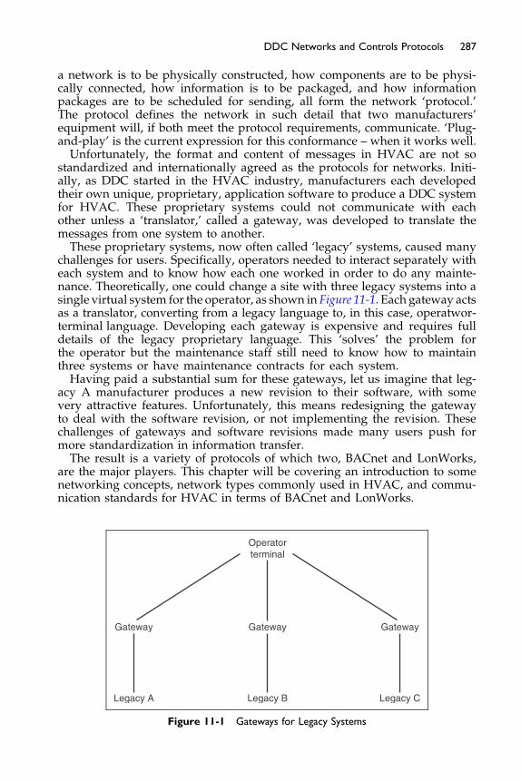
287DDC Networks and Controls Protocols
a network is to be physically constructed, how components are to be physi-cally connected, how information is to be packaged, and how informationpackages are to be scheduled for sending, all form the network ‘protocol.’The protocol defines the network in such detail that two manufacturers’equipment will, if both meet the protocol requirements, communicate. ‘Plug-and-play’ is the current expression for this conformance – when it works well.Unfortunately, the format and content of messages in HVAC are not so
standardized and internationally agreed as the protocols for networks. Initi-ally, as DDC started in the HVAC industry, manufacturers each developedtheir own unique, proprietary, application software to produce a DDC systemfor HVAC. These proprietary systems could not communicate with eachother unless a ‘translator,’ called a gateway, was developed to translate themessages from one system to another.These proprietary systems, now often called ‘legacy’ systems, caused many
challenges for users. Specifically, operators needed to interact separately witheach system and to know how each one worked in order to do any mainte-nance. Theoretically, one could change a site with three legacy systems into asingle virtual system for the operator, as shown in Figure 11-1. Each gateway actsas a translator, converting from a legacy language to, in this case, operatwor-terminal language. Developing each gateway is expensive and requires fulldetails of the legacy proprietary language. This ‘solves’ the problem forthe operator but the maintenance staff still need to know how to maintainthree systems or have maintenance contracts for each system.Having paid a substantial sum for these gateways, let us imagine that leg-
acy A manufacturer produces a new revision to their software, with somevery attractive features. Unfortunately, this means redesigning the gatewayto deal with the software revision, or not implementing the revision. Thesechallenges of gateways and software revisions made many users push formore standardization in information transfer.The result is a variety of protocols of which two, BACnet and LonWorks,
are the major players. This chapter will be covering an introduction to somenetworking concepts, network types commonly used in HVAC, and commu-nication standards for HVAC in terms of BACnet and LonWorks.
Gateway Gateway Gateway
Legacy A Legacy B Legacy C
Operatorterminal
Figure 11-1 Gateways for Legacy Systems

288 Fundamentals of HVAC Control Systems
11.2 System Hardware Architecture
When DDC systems started to enter the commercial and institutional HVACcontrol, 30 years ago, computers were very expensive and telephone cablewas relatively inexpensive. These first systems typically had a few generalpurpose computers programmed to be controllers, and long multi-core cablesto input and output devices. The communication requirements between com-puters and the operator workstation were not great, so a simple, dedicated,network worked well. Each controller computer was hard wired to numerousI/O points, as generally indicated in Figure 11-2.
In the following years, the relative cost of controllers dropped substantiallyand the cost of installing cable rose. The reduction in controller cost waspartly due to the fall in microprocessor cost but also because manufacturerswere making the microprocessors specifically as HVAC controllers insteadof programming general purpose computers to do the task.
This reduction in cabling to points is well illustrated in the VAV box con-troller. The VAV controller is now a microprocessor card mounted in the samehousing as the damper operator. It has few inputs and outputs all to do withthe one VAV box in its immediate area.
CC
Operatorworkstation
2 general purposecomputer/controllers
Muti-pair telephonecables aroundbuilding/site
Figure 11-2 Initial DDC System Layout
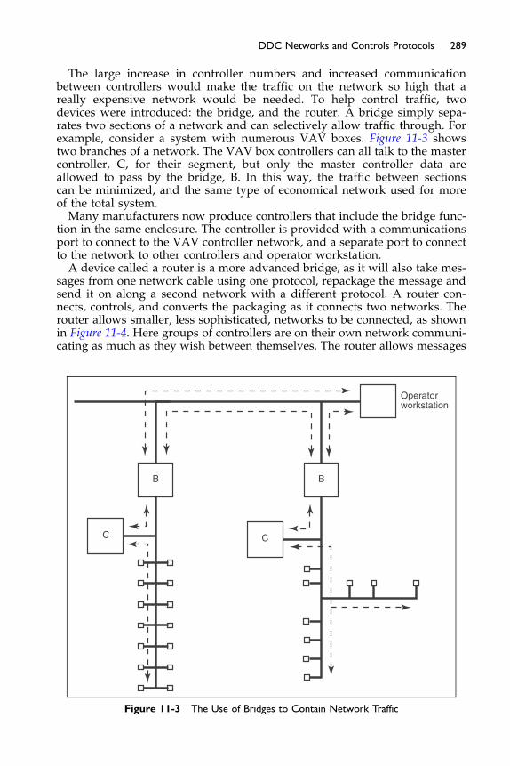
289DDC Networks and Controls Protocols
The large increase in controller numbers and increased communicationbetween controllers would make the traffic on the network so high that areally expensive network would be needed. To help control traffic, twodevices were introduced: the bridge, and the router. A bridge simply sepa-rates two sections of a network and can selectively allow traffic through. Forexample, consider a system with numerous VAV boxes. Figure 11-3 showstwo branches of a network. The VAV box controllers can all talk to the mastercontroller, C, for their segment, but only the master controller data areallowed to pass by the bridge, B. In this way, the traffic between sectionscan be minimized, and the same type of economical network used for moreof the total system.Many manufacturers now produce controllers that include the bridge func-
tion in the same enclosure. The controller is provided with a communicationsport to connect to the VAV controller network, and a separate port to connectto the network to other controllers and operator workstation.A device called a router is a more advanced bridge, as it will also take mes-
sages from one network cable using one protocol, repackage the message andsend it on along a second network with a different protocol. A router con-nects, controls, and converts the packaging as it connects two networks. Therouter allows smaller, less sophisticated, networks to be connected, as shownin Figure 11-4. Here groups of controllers are on their own network communi-cating as much as they wish between themselves. The router allows messages
Operatorworkstation
C C
BB
Figure 11-3 The Use of Bridges to Contain Network Traffic
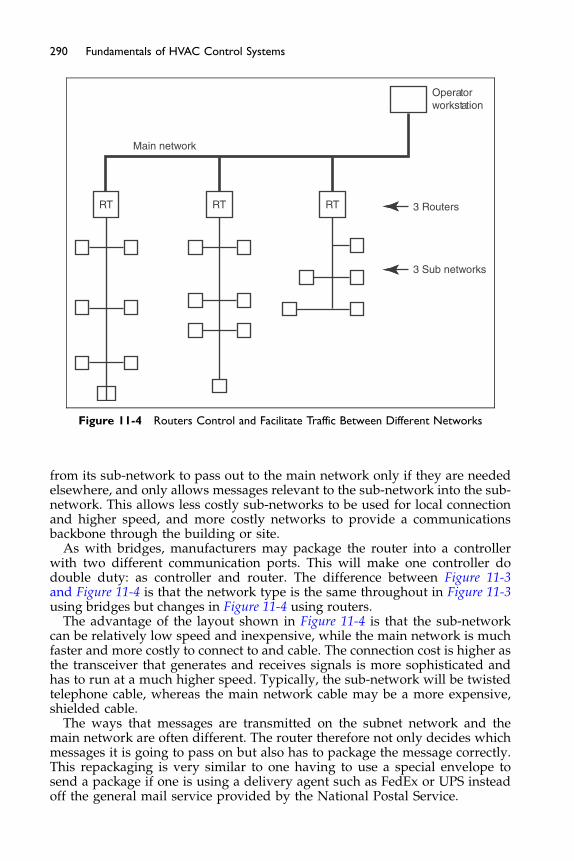
Operatorworkstation
3 Routers
3 Sub networks
Main network
RT RT RT
Figure 11-4 Routers Control and Facilitate Traffic Between Different Networks
290 Fundamentals of HVAC Control Systems
from its sub-network to pass out to the main network only if they are neededelsewhere, and only allows messages relevant to the sub-network into the sub-network. This allows less costly sub-networks to be used for local connectionand higher speed, and more costly networks to provide a communicationsbackbone through the building or site.
As with bridges, manufacturers may package the router into a controllerwith two different communication ports. This will make one controller dodouble duty: as controller and router. The difference between Figure 11-3and Figure 11-4 is that the network type is the same throughout in Figure 11-3using bridges but changes in Figure 11-4 using routers.
The advantage of the layout shown in Figure 11-4 is that the sub-networkcan be relatively low speed and inexpensive, while the main network is muchfaster and more costly to connect to and cable. The connection cost is higher asthe transceiver that generates and receives signals is more sophisticated andhas to run at a much higher speed. Typically, the sub-network will be twistedtelephone cable, whereas the main network cable may be a more expensive,shielded cable.
The ways that messages are transmitted on the subnet network and themain network are often different. The router therefore not only decides whichmessages it is going to pass on but also has to package the message correctly.This repackaging is very similar to one having to use a special envelope tosend a package if one is using a delivery agent such as FedEx or UPS insteadoff the general mail service provided by the National Postal Service.
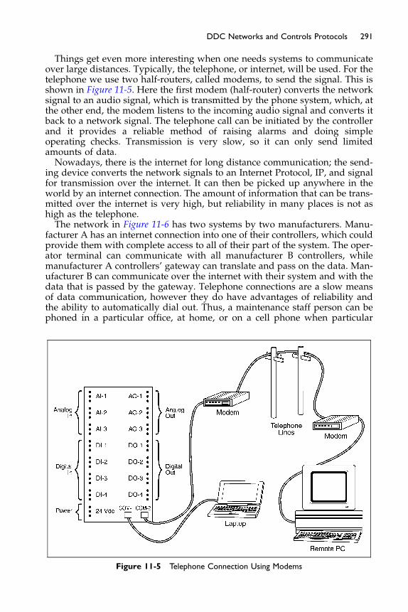
291DDC Networks and Controls Protocols
Things get even more interesting when one needs systems to communicateover large distances. Typically, the telephone, or internet, will be used. For thetelephone we use two half-routers, called modems, to send the signal. This isshown in Figure 11-5. Here the first modem (half-router) converts the networksignal to an audio signal, which is transmitted by the phone system, which, atthe other end, the modem listens to the incoming audio signal and converts itback to a network signal. The telephone call can be initiated by the controllerand it provides a reliable method of raising alarms and doing simpleoperating checks. Transmission is very slow, so it can only send limitedamounts of data.Nowadays, there is the internet for long distance communication; the send-
ing device converts the network signals to an Internet Protocol, IP, and signalfor transmission over the internet. It can then be picked up anywhere in theworld by an internet connection. The amount of information that can be trans-mitted over the internet is very high, but reliability in many places is not ashigh as the telephone.The network in Figure 11-6 has two systems by two manufacturers. Manu-
facturer A has an internet connection into one of their controllers, which couldprovide them with complete access to all of their part of the system. The oper-ator terminal can communicate with all manufacturer B controllers, whilemanufacturer A controllers’ gateway can translate and pass on the data. Man-ufacturer B can communicate over the internet with their system and with thedata that is passed by the gateway. Telephone connections are a slow meansof data communication, however they do have advantages of reliability andthe ability to automatically dial out. Thus, a maintenance staff person can bephoned in a particular office, at home, or on a cell phone when particular
Figure 11-5 Telephone Connection Using Modems
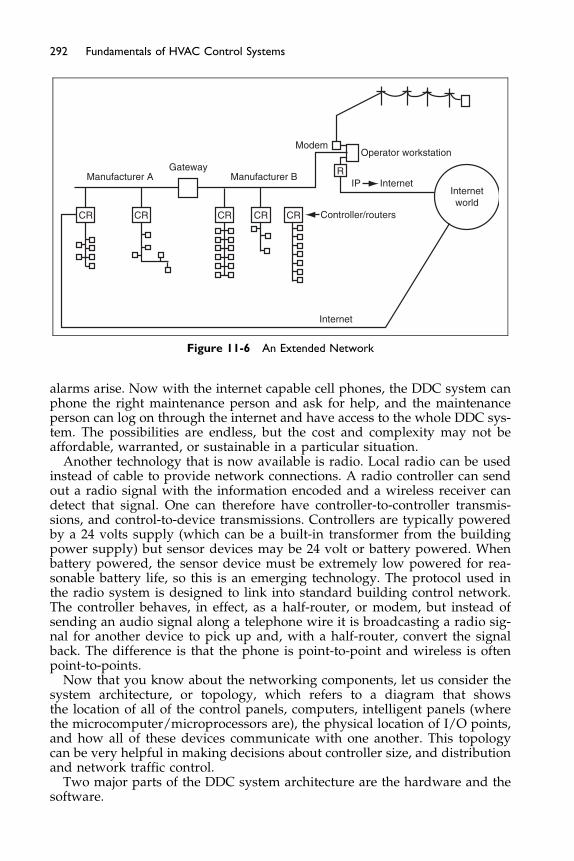
Manufacturer A Manufacturer BGateway
CR CR CR CR CR
R
Controller/routers
IP
Internet
InternetInternetworld
ModemOperator workstation
Figure 11-6 An Extended Network
292 Fundamentals of HVAC Control Systems
alarms arise. Now with the internet capable cell phones, the DDC system canphone the right maintenance person and ask for help, and the maintenanceperson can log on through the internet and have access to the whole DDC sys-tem. The possibilities are endless, but the cost and complexity may not beaffordable, warranted, or sustainable in a particular situation.
Another technology that is now available is radio. Local radio can be usedinstead of cable to provide network connections. A radio controller can sendout a radio signal with the information encoded and a wireless receiver candetect that signal. One can therefore have controller-to-controller transmis-sions, and control-to-device transmissions. Controllers are typically poweredby a 24 volts supply (which can be a built-in transformer from the buildingpower supply) but sensor devices may be 24 volt or battery powered. Whenbattery powered, the sensor device must be extremely low powered for rea-sonable battery life, so this is an emerging technology. The protocol used inthe radio system is designed to link into standard building control network.The controller behaves, in effect, as a half-router, or modem, but instead ofsending an audio signal along a telephone wire it is broadcasting a radio sig-nal for another device to pick up and, with a half-router, convert the signalback. The difference is that the phone is point-to-point and wireless is oftenpoint-to-points.
Now that you know about the networking components, let us consider thesystem architecture, or topology, which refers to a diagram that showsthe location of all of the control panels, computers, intelligent panels (wherethe microcomputer/microprocessors are), the physical location of I/O points,and how all of these devices communicate with one another. This topologycan be very helpful in making decisions about controller size, and distributionand network traffic control.
Two major parts of the DDC system architecture are the hardware and thesoftware.

293DDC Networks and Controls Protocols
In general, the hardware can be described as all of the control devices thatmake up the system – the PC computer, laptop, displays, controllers, sensors,relays, timers, transformers, etc. – the parts of the control system that you cantouch and feel. They are typically depicted on an architecture diagram thatoutlines the hardware configurations in a broad-brush fashion.Architecture diagrams can take on many forms (see Figure 11-7) Some show
the layout of the hardware in a composite manner, and some, Figure 11-8,show how the hierarchy of the system lays out with the communications ofthe Building Management Systems (BMS).Depending on the size of the DDC system, and how much integration into
different manufacturers’ controllers and protocols is provided, the architec-ture can be as simple as a one-line diagram or may be complex involving mul-tiple levels of communication protocols and Operator Workstations. Alsoincluded in the architecture would be the ties to outside phone lines, intranetor internet.The simplest DDC system is a stand-alone panel with input and output,
I/O, points included as an integral part of the panel. The term stand-alonemeans no communication with other controllers is required for the systemto work; the panel includes all the required components, such as microproces-sor, memory and I/O boards. Optional features include a timeclock (usuallyrequired for on/off time scheduling) and power supply (required eitherwithin the control panel or as an external accessory). However, in practice,even the smallest DDC controller will accept more I/O points. The actualI/O point count varies widely among manufacturers.Note that the degree of stand-alone ability can vary. As an example, con-
sider a controller operating an air-handling unit with an economizer damper
Figure 11-7 Architecture Layout
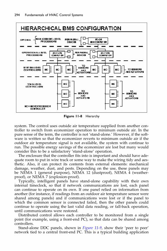
Figure 11-8 Hierarchy
294 Fundamentals of HVAC Control Systems
system. The control uses outside air temperature supplied from another con-troller to switch from economizer operation to minimum outside air. In thepure sense of the term, the controller is not ‘stand-alone.’ However, if the soft-ware is written so that the economizer reverts to minimum outside air if theoutdoor air temperature signal is not available, the system with continue torun. The possible energy savings of the economizer are lost but many wouldconsider this to be a satisfactory ‘stand-alone’ operation.
The enclosure that the controller fits into is important and should have ade-quate room to put in wire track or some way to make the wiring tidy and aes-thetic. Also, it can protect its contents from external elements: mechanicaldamage, weather, dust, and pests. Depending on the use, these panels maybe NEMA 1 (general purpose), NEMA 12 (dustproof), NEMA 4 (weather-proof), or NEMA 7 (explosion-proof).
Typically, intelligent panels have stand-alone capability with their owninternal timeclock, so that if network communications are lost, each panelcan continue to operate on its own. If one panel relied on information fromanother (for instance, if readings from an outdoor air temperature sensor wereshared among panels) and if communications were lost or if the panel towhich the common sensor is connected failed, then the other panels couldcontinue to operate using the last valid data reading, or fall-back operation,until communications were restored.
Distributed control allows each controller to be monitored from a singlepoint (for example, using a front-end PC), so that data can be shared amongcontrollers.
Stand-alone DDC panels, shown in Figure 11-9, show their ‘peer to peer’network tied to a central front-end PC. This is a typical building application

Stand-aloneDDC
Stand-aloneDDC
Stand-aloneDDC
PC
Figure 11-9 Distributed Intelligence þ Peer-to-Peer Network
295DDC Networks and Controls Protocols
where the owners can easily monitor and operate their buildings indepen-dently of the controls vendor after initial installation and setup.Some systems have two-tiered and multi-tiered communications architec-
ture with this design: intelligent controllers are connected together by ahigh-level, high-speed local area network, often using general-purpose LANprotocols such as ARCNET and Ethernet. The front-end PC usually connectsto the control system on this LAN. The controllers then connect to and man-age other lower level, lower speed LANs, often using a protocol proprietaryto the DDC manufacturer. To this second network, a combination of special-purpose and multi-purpose controllers may be connected, each sharing infor-mation with the network controller, which can then pass the information onto other systems on the high-level LAN. The concept of large ‘enterprisewide’ facility operations for multi-site locations is driving new and complexrequirements for BAS systems.
Sample Controllers
Controllers come in many configurations. A general all-purpose type control-ler that has a large number of outputs and inputs in a single controller panel isshown in Figure 11-10. The physical unit is shown in Figure 11-11.Some application-specific controllers have small and compact point densities
with small amount of outputs and inputs, usually just enough to perform theirapplication. An example of a VAV box controller is shown in Figure 11-12. Notethat the thermostat has a network access port, in this case called E-bus networkaccess. This allows maintenance staff to plug a communication unit into thethermostat to monitor, change, and control the controller. This allows the main-tenance staff communication access without having to, typically, get above theceiling to the VAV box controller. Note also that the controller housing also con-tains the damper motor minimizing installation labor.Typically; the hardware is laid out so the wiring is simplified for the field
installer. Notice the wiring information given at the controller device levelitself. This is very helpful to the installer and maintenance technician. Fig-ure 11-13 shows a room thermostat, a true application-specific controller.

Figure 11-10 Typical General-Purpose Controller Diagram
296 Fundamentals of HVAC Control Systems
It is designed to accept signals from several devices which may not be usedincluding a motion sensor and humidity sensor. The device is designed todeal with the most likely requirements and is produced in quantity. Theadded hardware cost is very small compared with buying a general purposecontroller and programming it for the specific situation.
11.3 Network Standards
Let us spend a moment revisiting the meaning of the word protocol. In theseHVAC control systems there are two types of protocol. The first is the protocolfor the HVAC information. Each controller needs to understand the meaningof the data being sent and to understand how to request data from other
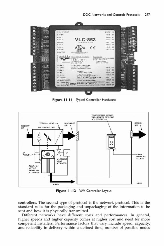
Figure 11-11 Typical Controller Hardware
Figure 11-12 VAV Controller Layout
297DDC Networks and Controls Protocols
controllers. The second type of protocol is the network protocol. This is thestandard rules for the packaging and unpackaging of the information to besent and how it is physically transmitted.Different networks have different costs and performances. In general,
higher speeds and higher capacity comes at higher cost and need for morecompetent installers. Performance factors that vary include speed, capacity,and reliability in delivery within a defined time, number of possible nodes
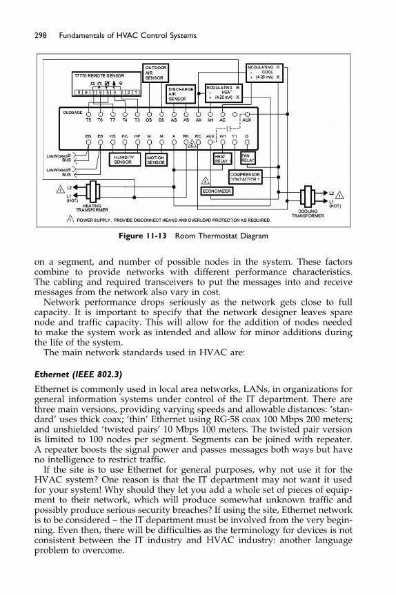
Figure 11-13 Room Thermostat Diagram
298 Fundamentals of HVAC Control Systems
on a segment, and number of possible nodes in the system. These factorscombine to provide networks with different performance characteristics.The cabling and required transceivers to put the messages into and receivemessages from the network also vary in cost.
Network performance drops seriously as the network gets close to fullcapacity. It is important to specify that the network designer leaves sparenode and traffic capacity. This will allow for the addition of nodes neededto make the system work as intended and allow for minor additions duringthe life of the system.
The main network standards used in HVAC are:
Ethernet (IEEE 802.3)
Ethernet is commonly used in local area networks, LANs, in organizations forgeneral information systems under control of the IT department. There arethree main versions, providing varying speeds and allowable distances: ‘stan-dard’ uses thick coax; ‘thin’ Ethernet using RG-58 coax 100 Mbps 200 meters;and unshielded ‘twisted pairs’ 10 Mbps 100 meters. The twisted pair versionis limited to 100 nodes per segment. Segments can be joined with repeater.A repeater boosts the signal power and passes messages both ways but haveno intelligence to restrict traffic.
If the site is to use Ethernet for general purposes, why not use it for theHVAC system? One reason is that the IT department may not want it usedfor your system! Why should they let you add a whole set of pieces of equip-ment to their network, which will produce somewhat unknown traffic andpossibly produce serious security breaches? If using the site, Ethernet networkis to be considered – the IT department must be involved from the very begin-ning. Even then, there will be difficulties as the terminology for devices is notconsistent between the IT industry and HVAC industry: another languageproblem to overcome.
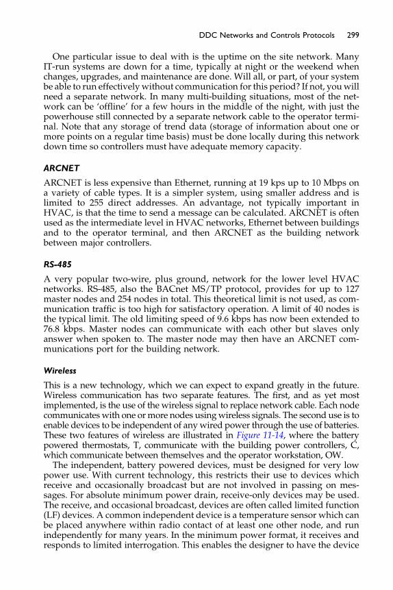
299DDC Networks and Controls Protocols
One particular issue to deal with is the uptime on the site network. ManyIT-run systems are down for a time, typically at night or the weekend whenchanges, upgrades, and maintenance are done. Will all, or part, of your systembe able to run effectivelywithout communication for this period? If not, youwillneed a separate network. In many multi-building situations, most of the net-work can be ‘offline’ for a few hours in the middle of the night, with just thepowerhouse still connected by a separate network cable to the operator termi-nal. Note that any storage of trend data (storage of information about one ormore points on a regular time basis) must be done locally during this networkdown time so controllers must have adequate memory capacity.
ARCNET
ARCNET is less expensive than Ethernet, running at 19 kps up to 10 Mbps ona variety of cable types. It is a simpler system, using smaller address and islimited to 255 direct addresses. An advantage, not typically important inHVAC, is that the time to send a message can be calculated. ARCNET is oftenused as the intermediate level in HVAC networks, Ethernet between buildingsand to the operator terminal, and then ARCNET as the building networkbetween major controllers.
RS-485
A very popular two-wire, plus ground, network for the lower level HVACnetworks. RS-485, also the BACnet MS/TP protocol, provides for up to 127master nodes and 254 nodes in total. This theoretical limit is not used, as com-munication traffic is too high for satisfactory operation. A limit of 40 nodes isthe typical limit. The old limiting speed of 9.6 kbps has now been extended to76.8 kbps. Master nodes can communicate with each other but slaves onlyanswer when spoken to. The master node may then have an ARCNET com-munications port for the building network.
Wireless
This is a new technology, which we can expect to expand greatly in the future.Wireless communication has two separate features. The first, and as yet mostimplemented, is the use of the wireless signal to replace network cable. Each nodecommunicates with one ormore nodes usingwireless signals. The second use is toenable devices to be independent of anywired power through the use of batteries.These two features of wireless are illustrated in Figure 11-14, where the batterypowered thermostats, T, communicate with the building power controllers, C,which communicate between themselves and the operator workstation, OW.The independent, battery powered devices, must be designed for very low
power use. With current technology, this restricts their use to devices whichreceive and occasionally broadcast but are not involved in passing on mes-sages. For absolute minimum power drain, receive-only devices may be used.The receive, and occasional broadcast, devices are often called limited function(LF) devices. A common independent device is a temperature sensor which canbe placed anywhere within radio contact of at least one other node, and runindependently for many years. In the minimum power format, it receives andresponds to limited interrogation. This enables the designer to have the device

T
T
T
T
T
C
~ ~
C
Operatorworkstation
Wiredpoints on
airhandling
unit
Figure 11-14 Wireless Network with Self- and Building-Powered Devices
300 Fundamentals of HVAC Control Systems
in very, very low power use, most of the time extending battery life. Battery lifewith a lithium ion battery can easily be 5 years and may reach 10 years.
As circuits with lower power demand become available, this option willincrease in popularity. Note that this technology will likely decrease first cost aswiring can easily be over 50% of the cost of an installed sensor. The cost of batteryreplacement includes the cost of the battery, finding the device, and replacing thebattery. This maintenance cost needs to be factored into system support costs.
The full function, FF, wireless node is provided with building power andcan pass on information as well as send and receive data. The full functionnodes can operate in a linear arrangement, topology, where signals have a sin-gle defined route from node to node to node (Figure 11-15a). Becoming morepopular is mesh topology, where full function nodes are arranged to be within
FF
LF
LF
LF
LF
LF
LF LFLF
LF
LF
LF
FF
hseM .bretsulc ,ratS .a
FF
FF
FF
FF
FF
Figure 11-15 Linear and Mesh Arrangements of Nodes

301DDC Networks and Controls Protocols
range of at least two other nodes and messages can be passed by any route(Figure 11-15b). This makes for a robust wireless system not affected by inter-ruptions in particular node to node paths as other paths will maintain com-munication routes.How robust is robust? It all depends. Wireless signals are significantly
affected by distance and materials – particularly metals. The signal attenu-ates (reduces) over a distance, and materials such as concrete attenuate thesignal level by absorption. Metal acts as a reflector and the greater the areaof metal, the greater the wireless signal is affected. Thus, a bus garage islikely to require nodes to be much closer together than a country hotel con-structed of wood, studs and wall board. This attenuation issue makes thelayout a try-and-see exercise. An experienced company can estimate thenode spacing required. On installation, signal strength tests must be carriedout to ensure adequate signal strength to, and from, each node to othernodes. If necessary, repeaters may have to be added or nodes moved. Arepeater is a device that receives and rebroadcasts the message: effectivelya signal power booster.Wireless is very different from hard-wired connections. Interference can
come from many sources, and an experienced supplier should be used forany significant installation. There is the building and its initial contents thatact as permanent attenuators. In addition, there are the things that move –furniture, people, and new partitions – to allow for. Finally, there is theinterference from other equipment such as lights, variable speed drives,elevators, and other radio equipment. The process is thus different fromspecifying a wire from A to B, installing it, and using it. With the wirelesscommunication, an initial layout must be tested and often adjusted toachieve full operation. This adjustment will often be done after signalstrength measurements have been taken on site to establish the wirelesssignal strengths.There are three radio frequencies generally used:
� 2.4 GHz frequency using the IEEE 802.15.4 standard. The system may beproprietary or, potentially, conform to the developing ZigBee™ Alliancestandard (www.zigbee.com). This frequency band requires low powerbut is limited in data transmission speed. Indoor range in the normalcommercial and institutional building for mesh arrangements is up to150 ft while non-mesh communication may reach 300 ft.
� 900 MHz. This frequency band has greater range than the 2.4 GHz bandbut can only be used in North America and Australia, which makes man-ufacturers’ development costs more difficult to recover.
� 800 MHz is used outside North America and Australia, and with thesame greater range but limited geographic area of use.
11.4 BACnet
BACnet is a protocol dealing with the HVAC information flow around net-works. It is an internationally accepted and approved protocol covered byISO Standard 16484, Part 5: 2003 (EN ISO 16484-5), A Data Communication Pro-tocol for Building Automation and Controls Networks Systems. In the HVAC

302 Fundamentals of HVAC Control Systems
industry there are three types of information protocol, with BACnet being thethird type in the set:
1. Proprietary protocols owned and used by individual manufacturers.They are generally incompatible with each other, and one needs a gate-way to translate information passing from one system to another.
2. Standard protocols, which are generally available protocols used by manycompanies but not subject to any internationally recognized standardorganizations. Modbus is an example of one of these de facto standards.It has become very widely used in electrical switchgear and boiler plants.
3. A standard protocol, where the protocol has been very clearly defined,is publicly available, and is recognized by standard authorities such as theAmericanNational Standard Institute (ANSI) and International Organizationfor Standardization (ISO).
ANSI/ASHRAE Standard 135-2004 BACnet a Data Communication Proto-col for Building Automation and Control Networks, BACnet, is a set of rulesabout controller hardware and software, specifically relating to communica-tion for HVAC, lighting, smart elevators, utility metering, and Physical AccessControls (PACs). Over time, this list will, no doubt, increase.
The Standard is a large and very technical document, nearing 1,000 pageswith addenda. For the person new to BACnet, the ASHRAE BACnet Commit-tee maintains a website at www.bacnet.org which provides numerous sourcesof information in a less daunting format.
The Standard contains rules about how information about points is to berepresented, how the information is to be formatted for transmission, andhow transceivers for different networks are to work. The information aboutpoints includes some mandatory items, several optional items, and proprietaryitems. The rules are open-ended in that there is choice in which are used andhow to add options. For BACnet controllers to interoperate they need to complywith compatible sets of rules. The standard includes mandatory rules in a fixedformat for the particular device. The rules define some mandatory communica-tion data for the device, some optional communication data, and the freedom toproduce proprietary communication data.
For example, a smart sensor must be able to identify itself (defined manda-tory), it may have adjustablemaximum andminimum end points for user adjust-ment (defined optional), and it could have the proprietary ability to report thehighest temperature the user had requested (proprietary). For interoperabilitybetween this device and another device the optional properties can be requestedbut for proprietary properties both devices have to know the content and formatof the proprietary information. If a BACnet system with proprietary content hasbeen installed when it comes time to extend the system other manufacturersBACnet devices will not be able to access this additional functionality withoutobtaining the propriety details from the original manufacturer.
BACnet deals with the transfer of data between devices. It does not dealwith the application program that runs the control loops, does stop/start,and all the other logic. It is similar to two people talking English to each other.One may be a native French speaker thinking in French and the other can bethinking in Spanish. Their ‘application programs’ are different but they areconverting the information into English words to exchange.

303DDC Networks and Controls Protocols
What is a PICS?
PICS stands for ‘protocol implementation conformance statement.’ It is basi-cally a BACnet spec sheet containing a list of a device’s BACnet capabilities.Every BACnet device is required to have one. It contains a general productdescription; details of a product’s BACnet capabilities; which LAN optionsare available; and a few other items relating to character sets and special func-tionality. A PICS is the place to start to see what a device’s capabilities are.Conversely, a specifier could draft a PICS as a way of conveying what BACnetcapabilities are desired for a particular job.
� Basic information identifying the vendor and describing the BACnetdevice.
� The BACnet Interoperability Building Blocks (BIBBs) supported by thedevice (both the required BIBBs and any additional BIBBs supported).
� Which of the six standardized BACnet device profile does it conform to(note that additional profiles are under review).
� All non-standard application services that are supported with details.� A list of all standard and proprietary object types that are supported with
details.� Network options supported.
BACnet International (BI) was formed to, among other things, provide testingfacilities so that manufacturers could have their device tested and approvedas conforming to specific device profiles. The BACnet Testing Lab, oper-ated by BACnet International, tests BACnet devices for conformance andinteroperability. It lists devices that pass its testing, and only those devicesare permitted to bear the BTL Mark. A sister lab run by the BACnet, Inter-est Group Europe, is operating in Europe. More information is available atwww.bacnetinternational.org/btl/btl.phpThis provides designers and users with a basic conformance which they can
use to facilitate interoperability of BACnet devices from different sources. Inaddition, testing tools are being developed to enable automated testing ofBACnet devices.BACnet can be considered on four levels:
1. Devices – controllers, what is in them.2. Objects – the constant and changing information in the real and virtual
points in the device.3. Services – definitions of how information can be requested and how
information can be sent as needed or to answer a request4. Networks – communicating with other devices.
1. Devices – Groups of Objects to Manage Activity
Devices are groups of points, called objects, plus instructions on how to askfor and receive information. A device might issue a request to obtain the cur-rent outside air temperature from a specific AI (analogue input) on its physi-cal device or another physical device. The abilities of a device to requestinformation from another device or to send information to another deviceare called BACnet interoperability building blocks, BIBBs. The simplest, the
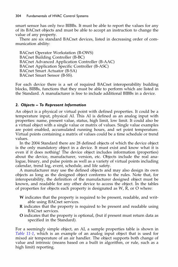
304 Fundamentals of HVAC Control Systems
smart sensor has only two BIBBs. It must be able to report the values for anyof its BACnet objects and must be able to accept an instruction to change thevalue of any property.
There are six standard BACnet devices, listed in decreasing order of com-munication ability:
BACnet Operator Workstation (B-OWS)BACnet Building Controller (B-BC)BACnet Advanced Application Controller (B-AAC)BACnet Application Specific Controller (B-ASC)BACnet Smart Actuator (B-SA)BACnet Smart Sensor (B-SS).
For each device there is a set of required BACnet interoperability buildingblocks, BIBBs, functions that they must be able to perform which are listed inthe Standard. A manufacturer is free to include additional BIBBs in a device.
2. Objects – To Represent Information
An object is a physical or virtual point with defined properties. It could be atemperature input, physical AI. This AI is defined as an analog input withproperties: name, present value, status, high limit, low limit. It could also bea virtual object with a single value or matrix of values. Single value examplesare point enabled, accumulated running hours, and set point temperature.Virtual points containing a matrix of values could be a time schedule or trendvalues.
In the 2004 Standard there are 28 defined objects of which the device objectis the only mandatory object in a device. It must exist and know what it iseven if it does nothing! The device object includes information (properties)about the device, manufacturer, version, etc. Objects include the real ana-logue, binary, and pulse points as well as a variety of virtual points includingcalendar, trend log, event, schedule, and life safety.
A manufacturer may use the defined objects and may also design its ownobjects as long as the designed object conforms to the rules. Note that, forinteroperability, the definition of the manufacturer designed object must beknown, and readable for any other device to access the object. In the tablesof properties for objects each property is designated as W, R, or O where:
W indicates that the property is required to be present, readable, and writ-able using BACnet services.
R indicates that the property is required to be present and readable usingBACnet services.
O indicates that the property is optional, (but if present must return data asspecified in the Standard).
For a seemingly simple object, an AI, a sample properties table is shown inTable 11-1, which is an example of an analog input object that is used formixed air temperature of an air handler. The object supports both change ofvalue and intrinsic (means based on a built in algorithm, or rule, such as ahigh limit) reporting.
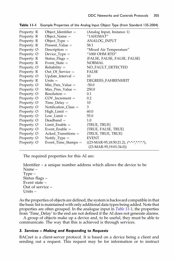
Table 11-1 Example Properties of the Analog Input Object Type (from Standard 135-2004)
Property: R Object_Identifier ¼ (Analog Input, Instance 1)Property: R Object_Name ¼ “1AH1MAT”Property: R Object_Type ¼ ANALOG_INPUTProperty: R Present_Value ¼ 58.1Property: O Description ¼ “Mixed Air Temperature”Property: O Device_Type ¼ “1000 OHM RTD”Property: R Status_Flags ¼ {FALSE, FALSE, FALSE, FALSE}Property: R Event_State ¼ NORMALProperty: O Reliability ¼ NO_FAULT_DETECTEDProperty: R Out_Of_Service ¼ FALSEProperty: O Update_Interval ¼ 10Property: R Units ¼ DEGREES_FAHRENHEITProperty: O Min_Pres_Value ¼ -50.0Property: O Max_Pres_Value ¼ 250.0Property: O Resolution ¼ 0.1Property: O COV_Increment ¼ 0.2Property: O Time_Delay ¼ 10Property: O Notification_Class ¼ 3Property: O High_Limit ¼ 60.0Property: O Low_Limit ¼ 55.0Property: O Deadband ¼ 1.0Property: O Limit_Enable ¼ {TRUE, TRUE}Property: O Event_Enable ¼ {TRUE, FALSE, TRUE}Property: O Acked_Transitions ¼ {TRUE, TRUE, TRUE}Property: O Notify_Type ¼ EVENTProperty: O Event_Time_Stamps ¼ ((23-MAR-95,18:50:21.2), (*-*-*,*:*:*.*),
(23-MAR-95,19:01:34.0))
The required properties for this AI are:
Identifier – a unique number address which allows the device to beName –Type –Status flags –Event state –Out of service –Units –
305DDC Networks and Controls Protocols
As theproperties of objects are defined, the system is backward compatible in thatthe basic list ismaintainedwith only additional data types being added.Note thatproperties are often grouped. In the analogue input in Table 11-1, the propertiesfrom ‘Time_Delay’ to the end are not defined if the AI does not generate alarms.A group of objects make up a device and, to be useful, they must be able to
communicate. The way that this is achieved is through services.
3. Services – Making and Responding to Requests
BACnet is a client-server protocol. It is based on a device being a client andsending out a request. This request may be for information or to instruct

306 Fundamentals of HVAC Control Systems
another device to do something or change something. A request might be‘send me the current setting of the damper’ while an instruction might be‘store this as your schedule’ or ‘set the occupancy flag to unoccupied.’ Thesemessages are called ‘services.’
The 35 services are defined-in-detail ways of asking for data and definedways of receiving requests and responding to the request. They are groupedinto:
� Alarm and event services
Alarm generation, alarm acknowledgment, request for list of currentalarms. Event services include reporting based on change of value, a pre-determined event (e.g. every hour, damper setting above 90%) or combi-nation of events.� File access servicesTransmission of file changes for sending out changes to softwareprograms.
� Object access servicesRead, write and change properties of objects.
� Remote device management servicesUsed to control remote devices, TURN OFF, TURN ON, synchronizetime, and proprietary messages and instructions.
� Virtual terminal servicesThis allows one BACnet device to interact with the application pro-gram in another device as if one had plugged a terminal into the otherdevice.
The Standard defines each service as BACnet Interoperability BuildingBlocks (BIBBs) listed in Annex K of the Standard. The single value request isthe ReadProperty BIBB, DS-RP. It comes in two versions. The A version,DS-RP-A, is the initiate version. The B version, DS-RP-B, is the execute, orrespond, version. So, a controller, or client, would contain DS-RP-A so thatit can ask a temperature sensor, or server, containing DS-RP-B for the currenttemperature. In effect, one device must know exactly how to ask the questionand the other device must know exactly how to interpret the question.
The BIBB includes a message number, what object (point) value is requested,and what property is wanted such as ‘present value.’ This BIBB will be sentout and the reply should be either the BIBB ReadPropertyAck which includesthe message number, object under consideration, and present value or the BIBBError which includes the message number, object identifier and message ‘nosuch object.’
Services include events such as requesting and receiving values for real andvirtual points and alarms; sending and receiving instructions to set datavalues, enable and disable points; setting up and distributing schedules andtrends; setting up and collecting trends; sending and receiving proprietaryinformation.
4. Network – Transporting Request and Responses
For BACnet devices to communicate, they must be connected to each other.This can be over a network or phone line and there are many options directly
307DDC Networks and Controls Protocols
available. In general, faster networks are more expensive both in cabling andthe transmitter/receiver.
Networks
Ethernet 10 and 100 Mbps on twisted pair cable, coaxial cable, fiber opticcableARCNET 2.5 MbpsMS/TP (master-slave/token-passing) < 1 Mbps, often 76.8 Kbps, twistedpair wiringLonTalk by EchelonPhone linePTP for phone lines or hardwired EIA-232 wire
InternetBACnet/IP using Broadcast Management Device (BBMD) for internet
communicationThe use of the internet opens up many new possibilities and the BACnet
protocol is being extended to make full use of the internet, including thetransmission of web pages. A simple example of the use of the internet isin multi-tenant buildings. Tenants can be provided with access to their partof the DDC system without the building system having to be physicallywired to any tenant computer. This avoids both physical cable coordinationwith tenants and network security issues.Within the building it enables staffto have a virtual thermostat – an image of a thermostat which shows the cur-rent temperature and set point, plus allowing them to raise or lower the setpoint within preset limits. Internet access can also allow tenants with spacein several buildings to have a single staff person access the DDC system inall their spaces.
The internet raises additional concerns about network security. Typi-cally, a networked DDC system will have security software whichrequires a password for access. Larger systems will have a hierarchy ofpasswords where the highest level gives access to everything and allowsany changes to be made. Lower levels of access provide more limitedaccess. The day-to-day operator may only have access to limited pointsand only be able to make simple adjustments including on/off control.Once access to the Internet is provided additional firewall security isneeded.
A router can be used between any of the networks to pass on the BACnetpackets in the changed transmission format. Thus, a large site could use Ether-net between buildings and to the operator workstation and MS/TP as the net-work (often called ‘field bus’) around the building. In this situation eachbuilding would include an Ethernet to MS/TP router. Then, when an exten-sion was added, the new vendor used ARCNET for their network requiringan Ethernet to ARCNET router as shown in Figure 11-16.The use of a gateway is common for large equipment, including boilers and
chillers. The chiller manufacturer may have its own proprietary control panel.A gateway can then transfer the necessary information from the chiller systeminto BACnet for transmission to BACnet devices. Typically, a limited menu ofdata is needed to go each way. From the operator to the chiller might be ‘turnon,’ ‘turn off,’ ‘set chilled water supply temperature to �F,’ ‘limit capacity to
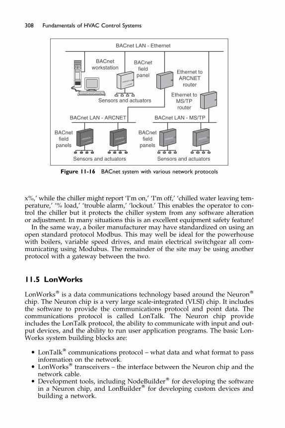
VENDOR CVENDOR C
VENDOR BVENDOR B
VENDOR A
BACnet LAN - Ethernet
BACnetworkstation
BACnetfield
panel
BACnetfield
panels
BACnetfield
panels
Sensors and actuators
Sensors and actuators Sensors and actuators
Ethernet toARCNET
router
BACnet LAN - ARCNET BACnet LAN - MS/TP
Ethernet toMS/TProuter
Figure 11-16 BACnet system with various network protocols
308 Fundamentals of HVAC Control Systems
x%,’ while the chiller might report ‘I’m on,’ ‘I’m off,’ ‘chilled water leaving tem-perature,’ ‘% load,’ ‘trouble alarm,’ ‘lockout.’ This enables the operator to con-trol the chiller but it protects the chiller system from any software alterationor adjustment. In many situations this is an excellent equipment safety feature!
In the same way, a boiler manufacturer may have standardized on using anopen standard protocol Modbus. This may well be ideal for the powerhousewith boilers, variable speed drives, and main electrical switchgear all com-municating using Modubus. The remainder of the site may be using anotherprotocol with a gateway between the two.
11.5 LonWorks
LonWorksW is a data communications technology based around the NeuronW
chip. The Neuron chip is a very large scale-integrated (VLSI) chip. It includesthe software to provide the communications protocol and point data. Thecommunications protocol is called LonTalk. The Neuron chip provideincludes the LonTalk protocol, the ability to communicate with input and out-put devices, and the ability to run user application programs. The basic Lon-Works system building blocks are:
� LonTalkW communications protocol – what data and what format to passinformation on the network.
� LonWorksW transceivers – the interface between the Neuron chip and thenetwork cable.
� Development tools, including NodeBuilderW for developing the softwarein a Neuron chip, and LonBuilderW for developing custom devices andbuilding a network.

309DDC Networks and Controls Protocols
These products are proprietary and are made by numerous manufacturers,and the technology has largely become an ANSI Standard. The name startswith Lon, meaning Local Operating Network, a network dealing with opera-tions. This neatly differentiates its focus from LAN, Local Area Network,which focus on all types of communication in a building or organization.Lon technology is aimed at the efficient flow of control data.Each node on the network contains three components: transceiver, Neuron chip,
and I/O circuits. Each Neuron chip has a number of defined Standard NetworkVariable Types (SNVT), and each type contains a network variable (nv) value.This network variable may be an input, nvi, or output, nvo. For example, theSNVT_temp contains the nvo value temperature in degrees centigrade. Thenetwork variables for HVAC are mostly dealing with the HVAC issues, but a feware needed to establish network behavior. Figure 11-18 shows the structure of onenode with just two of many network variables: temperature input and heateroutput. A VAV node, for example, has eight mandatory and 24 optional variables.Each nv has a rigorously defined format. Temperature, for example, is
defined as being between -273.17 and þ327.66�C with a resolution of 0.01�C.When a temperature is transmitted it is binary coded within this range, sentand decoded by another node. If one wants to display a temperature in �F, thenit must be converted from �C before displaying. This level of formality is chosento minimize program size and message size. Thus, sending a temperaturefrom one temperature output to a temperature input only requires sendingthe number representing the temperature.A range of published standard Functional Profiles define all the Network
Variables in the node. These profiles range from the simple temperature sen-sor to roof top unit controller in the HVAC field as well as lighting, smoke/fire detection, and specialized industrial profiles.The standardization around the Neuron chip and setup equipment makes for
relatively easy entry into the small scale DDC controls business. The Node-Builder is used to program each node. Then LonBuilder is used to modeland configure the network. Including a Network Service Interface moduleallows an operator workstation to be included. For a small system it is relativelysimple. However, larger DDC systems are more easily tested and configuredwith manufacturer specific development tools. Here the issue of interoperabil-ity becomes a challenge as a system installed by one supplier may have to becompletely reprogrammed for another supplier to make additions or changes.The development and control of the technology is largely controlled by
LonMark International (LMI) and LonMark Americas (LMA), non-profitorganizations with world wide membership of interested parties who developand maintain the interoperability rules and guidelines for LonWorks applica-tion. LMI operates a testing and certification program for devices. Details oftested devices, manufacturers and all about LonWorks are available atwww.lonmark.orgAlthough BACnet and LonWorks are not compatible the LonTalk network
protocol may be used to transport BACnet packets of information betweenBACnet devices. This does not enable BACnet devices to communicate witha standard LonMark certified device. A gateway would be required to dothe necessary translation between the dissimilar data protocols.In the hypothetical example in Figure 11-17 there are two LonMark and two
BACnet devices on the same LonTalk network. The two LonMark devices can
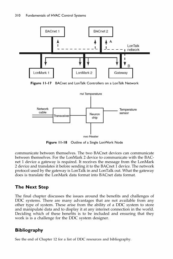
Figure 11-18 Outline of a Single LonWork Node
Figure 11-17 BACnet and LonTalk Controllers on a LonTalk Network
310 Fundamentals of HVAC Control Systems
communicate between themselves. The two BACnet devices can communicatebetween themselves. For the LonMark 2 device to communicate with the BAC-net 1 device a gateway is required. It receives the message from the LonMark2 device and translates it before sending it to the BACnet 1 device. The networkprotocol used by the gateway is LonTalk in and LonTalk out. What the gatewaydoes is translate the LonMark data format into BACnet data format.
The Next Step
The final chapter discusses the issues around the benefits and challenges ofDDC systems. There are many advantages that are not available from anyother type of system. These arise from the ability of a DDC system to storeand manipulate data and to display it at any internet connection in the world.Deciding which of these benefits is to be included and ensuring that theywork is is a challenge for the DDC system designer.
Bibliography
See the end of Chapter 12 for a list of DDC resources and bibliography.
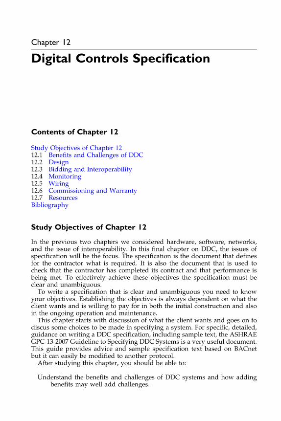
Chapter 12
Digital Controls Specification
Contents of Chapter 12
Study Objectives of Chapter 1212.1 Benefits and Challenges of DDC
12.2 Design 12.3 Bidding and Interoperability 12.4 Monitoring 12.5 Wiring 12.6 Commissioning and Warranty 12.7 Resources BibliographyStudy Objectives of Chapter 12
In the previous two chapters we considered hardware, software, networks,and the issue of interoperability. In this final chapter on DDC, the issues ofspecification will be the focus. The specification is the document that definesfor the contractor what is required. It is also the document that is used tocheck that the contractor has completed its contract and that performance isbeing met. To effectively achieve these objectives the specification must beclear and unambiguous.To write a specification that is clear and unambiguous you need to know
your objectives. Establishing the objectives is always dependent on what theclient wants and is willing to pay for in both the initial construction and alsoin the ongoing operation and maintenance.This chapter starts with discussion of what the client wants and goes on to
discus some choices to be made in specifying a system. For specific, detailed,guidance on writing a DDC specification, including sample text, the ASHRAEGPC-13-2007 Guideline to Specifying DDC Systems is a very useful document.This guide provides advice and sample specification text based on BACnetbut it can easily be modified to another protocol.After studying this chapter, you should be able to:
Understand the benefits and challenges of DDC systems and how addingbenefits may well add challenges.

312 Fundamentals of HVAC Control Systems
Be aware of the issues of interoperability when choosing and bidding DDCsystems.
Have an understanding of some of the possibilities of monitoring perfor-mance of DDC systems.
Be aware of the electrical issues that arise in DDC systems.Know where to look on the internet for more information on DDC systems.
12.1 Benefits and Challenges of DDC
DDC systems can be extremely sophisticated and perform control logic thatwas quite impossible with any previous system. Unfortunately, many ownersdo not have operating and maintenance staff that are trained to understandand utilize the available potential of DDC. In addition, owner’s staff oftendo not understand even the simplest ways of monitoring system energyperformance. As a result, the anticipated control performance may not bemet and the energy consumption may be much higher than expected or isnecessary.
To deal as effectively as possible with this issue, a designer must start aproject by finding out the owner’s business motivation, and likely operationand maintenance abilities. The initial owner may be a developer who is goingto sell the building and is not particularly concerned about performance orenergy costs. At the other extreme are the owners who are building a perfor-mance and energy showpiece for their head office. In the first case, a simplesystem with little sophistication will likely suit the situation. In the secondcase it will be valuable to work up the project objectives with the owner,the architect, and electrical designer so that there is a common, agreed set ofproject objectives and strategies.
This cooperative approach will help use a systems approach to designrather than the (oversimplified) situation where the architect designs thebuilding and then mechanical and electrical designers prepare their design.By systems design we mean considering the building as a whole system anddesigning the architecture, mechanical and electrical, to be efficient ratherthan considering each component separately. A mechanical example for acooler climate is putting funds into high performance windows and omittingperimeter heating. This example does not produce a more complex system foroperation and maintenance.
A combined mechanical and electrical example is using occupancy sensorsto switch off lights and to provide a signal to the HVAC system to reduce out-side air and allow temperatures change to the unoccupied limits. Althoughthis approach has the potential to reduce lighting and HVAC energy con-sumption, it also raises the complexity of the HVAC DDC controls. Is theowner committed to providing the resources to run such a system effectively?
When first discussing the DDC system with an owner it is useful to havea clear understanding of the benefits and challenges of DDC. The followingset of nine benefits is taken from the ASHRAE GPC-13-2007 Guideline toSpecifying DDC Systems, with additional comments.
1. DDC systems can reduce energy costs by enabling mechanical systems tooperate at peak efficiency. Equipment can be scheduled to run only when
313Digital Controls Specification
required and therefore generate only the required capacity at any time.Additional savings are possible if the DDC system is used for moresophisticated purposes than timeclocks or conventional controls. If theDDC system simply duplicates the function of these devices, there maynot be a significant reduction in energy consumption.
“Operate at peak efficiency” what does this mean? How will the clientknow what the initial efficiency is and what it is in a month, a year, adecade? Efficiency is generally defined as useful output divided by totalinputs. In HVAC systems “useful output” is keeping a process or peoplein the required environmental conditions. Unfortunately we cannot mea-sure comfort and are limited to measuring cooling output, which is notan entirely satisfactory metric. We will consider the efficiency of a chilledwater plant in a later section and how that may be monitored.
When designing a system think about “What has to be providedwhen?” In addition to time scheduling, there is the issue of “How muchmust be provided?” Simple examples include adjusting the outside airvolume to match actual occupancy needs and adjusting duct static pres-sures down so as to provide only the required airflow.
Even scheduled running hours can often be significantly reduced ifoccupants can turn on the system for their area for a limited time (2hours for example) when they are present earlier, or later, than the coreoperating hours.
Every watt of lighting in hot weather adds to the cooling load, so coop-erating with the lighting designer to minimize lighting loads and lightingon time also reduce cooling loads. People are generally poor at turningoff unnecessary lighting, so automating switch-off can produce lightingpower savings of 50% or more.
2. DDC systems have extensive functionality that permit the technologyto be used in diverse applications, such as commercial HVAC, surgicalsuites, and laboratory clean rooms. For example, they can be used tomeasure the amount of air delivered to each area, compare this to theventilation needs of the building, and then vary the amount of outdoorair introduced to meet the ventilation requirements of ANSI/ASHRAEStandard 62-2007. This level of control is not practical with pneumaticor electronic controls.
The level of additional functionality available through the use of DDCoften requires a more carefully designed HVAC system and bettertrained staff to effectively operate it. Be very careful not to over designfor the staffing capabilities, and to ensure that the control logic is clearto the operating staff.
Note that there is considerable scope for automatic fault detection inDDC systems but it is not for free. Manufacturers and independent orga-nizations are now offering fault detection programs and independentdata analysis tools that will become more readily available and easierto implement in the future. Software can be provided on the system orthe system can be interrogated over the internet and the analysis andreports generated at the office of the service provider.
3. A DDC system that controls HVAC systems in commercial, institutional,and multi-family residential buildings will provide tighter control overthe building systems. This means that temperatures can be controlled

314 Fundamentals of HVAC Control Systems
more accurately, and system abnormalities can be identified and cor-rected before they become serious (e.g. equipment failure or dealing withoccupant complaints).
A DDC system cannot overcome system design problems. Undercapacity, poor airflow in occupied zones, and an inability to removemoisture without overcooling are design flaws not control flaws. Noadditional DDC sophistication will resolve these issues. Be very carefulto avoid blaming the DDC controls until it is clear that the system hasthe capacity to perform. This will avoid wasting considerable resources,making the DDC system seem unsatisfactory, and generally frustratingall parties.
In addition to providing tighter control, DDC can also be used to provideoccupant control not practical with other systems. For example, providingoccupant adjustable thermostats is a real challenge in many buildings asthe occupants make extreme changes. With a DDC system, the thermostatlimits can be individually set with a narrow band, say 73�F to 78�F insummer. This prevents anyone turning the thermostat down to 65�For even lower and having the cooling running flat out to produce alower-than-necessary temperature and excessive energy consumption.
Systems with internet access can be set up so that occupants can adjust,within limits, the temperature in their space using their own PC andstandard internet browser. This may be considered as a valuable featureto the owner of a high end office tower with demanding tenants, or as acomplete waste of money by another owner.
4. In addition to commercial HVAC control, DDC can be used to controlor monitor elevators and other building systems including fire alarm,security, and lighting. This enhances the ability of maintenance staff/building operators to monitor these systems.
Note that the speed of response and circuit monitoring usuallyrequires specialist DDC equipment to control non-HVAC systems. Thus,the controller running an HVAC plant may well be a different controllerthan the controller running the security system in that area. Both control-lers may use the same data and communication protocols on the samenetwork and appear as the same for the operator at their workstation.
More and more frequently the security, fire, and other systems provideinputs to the DDC system, even if they are not integral with the buildingHVAC system.
Several HVAC controls manufacturers are now providing lighting andaccess control. Note that open bidding becomes more difficult withincreasing integration of disciplines, and requirements for all areas mustbe very clearly identified for getting bids. This integration is movingtowards a Cybernetic Building System (CBS) which involves intelligentcontrol, operation, and reporting of performance and problems. Thecapability exists with DDC systems to include self-commissioning.Examples include controllers which retune parameters as conditionschange. A useful example is on a large air-handling unit, altering PIDloop parameters when changing from controlling the heating coil inwinter to cooling coil in summer.
5. DDC allows the user to perform intricate scheduling and collect alarmsand trend data for troubleshooting problems. The alarm and trend
315Digital Controls Specification
features permit the operator to learn the heartbeat of the system. Observ-ing how a mechanical system performs under different load conditionsallows the programming to be fine-tuned and permits the operator toanticipate problems. This allows the occupants’ comfort concerns to bedealt with promptly before the problems become serious.
The ability to collect trend data is particularly valuable both in settingup the system to operate but also in ongoing checking on performance.For ongoing checking, some standard trends and reports should beestablished and included in the installation contract requirements.
6. Many DDC systems can provide programming and graphics that allowthe system to serve as the building documentation for the operator. Thisis valuable since paper copies of the system documentation are oftenmisplaced.
The graphic display of the systems with current operating data is amajor advantage of DDC. On larger systems it is very important thatthe hierarchy of displays and their format makes it easy for the staff tonavigate quickly and reliably to what they want displayed.
7. A DDC system requires significantly less maintenance than pneumaticcontrols. Pneumatic controls need regular maintenance and must beperiodically recalibrated. The use of DDC results in lower preventivemaintenance costs due to calibration and also lower repair costs forreplacement of pneumatic or electromechanical devices that degradeover time. All systems require some maintenance. Sensors such as rela-tive humidity and pressure sensors require regular calibration regardlessof what type of system they serve.
The actuators and mechanical parts of the system, valves and dampers,will still need maintenance and will still fail. Automatic detection of fail-ure is particularly valuable for these components.
8. DDC systems reduce labor costs through remote monitoring and trouble-shooting. Paying a technician to drive to the building to deal with everyproblem can be minimized with DDC. In many cases, on-site operationscan be eliminated or reduced to a single shift. Problems with the buildingare called out to a central monitoring service or to a technician with apager, and often may be rectified from remote locations by modem.
External monitoring and maintenance can be contracted to an externalorganization. The monitoring can be done from anywhere in the worldwhere internet service is available, although the hands-on maintenancewill need to be from a local provider.
9. DDC systems are programmable devices. As the needs of a buildingchange, the system can be reprogrammed to meet the new requirements.
This is both an advantage and, unfortunately, a disadvantage. Unless
the operating staff really understand and agree with the control pro-cesses they can, and do, modify things. Often the result is very poorbuilding performance. One of the advantages of having the system formally commissioned(having a separate commissioning agent test and verify the correct instal-lation and performance of the system) is that there is a clear definition ofhow the system was operating when installed. This knowledge makeslater checking on performance much easier as one has verified initialoperation.

316 Fundamentals of HVAC Control Systems
12.2 Design
Your specification will usually be written after the supporting system dia-grams and points lists have been completed. Start the system design by divid-ing the project into its main systems, typically: air handler plus associatedzone controls; boilers; and chilled water system. For each system work upthe control sequence of operations for:
normal operations, including: unoccupied; startup for occupied on schedule;startup for occupied outside schedule; summer; winter; and loadshedding.
failures, including: freeze protection; excess humidity; network communica-tion lost; power failure; and restart.
special situations, including: fire/smoke control; fireman operation; andaccess triggered events.
data collection: specific trend logs; running hours; and energy usage.
Note that, in some situations, it is simpler and less confusing to completethe HVAC system controls first. Then consider the special situations sepa-rately and their overriding effect on the individual HVAC systems controls,as indicated in Figure 12-1. As an example, when a fire detector goes intoalarm in System 1 what should happen in Systems 1, 2, and 3, the lightingcontrols (all means of escape routes lighting on), and access system?
In many buildings there are several almost identical systems. In this casethe sequence of operations for a base system can be produced with addi-tions/deletions for each of the other similar systems. Be very clear aboutwhich variations apply to which systems to minimize confusion and mistakes.
Based on the sequence of operations, a hardware (analog input, AI, analogoutput AO, binary input BI, binary output BO) and software points list is pro-duced. This list should identify whether the points are to be trended andwhether the trend is to be based on a time interval (every 15 minutes), changeof value (fan on to off), or amount of change in measured variable (�5% rela-tive humidity). The points list is also a convenient place to identify whichpoints are to be shown on the operator workstation graphics. Many of the soft-ware points known at this time will be alarms and these may be shown on the
Lighting
Fire/Smoke
Access
System 1
System 2
System 3
Boiler System
Chilled Water System
HVAC SystemsOther Systems
Figure 12-1 Superimposing Control Requirements from Other Systems
317Digital Controls Specification
graphics as well as announced as alarms. For example, a high mixed air tem-perature alarm could require the mixed air temperature to flash on the screen.Some designers also choose to make up a numbered schedule of graphics forthe operator workstation. The points list can then have the correct graphicidentifiers against relevant points.The points list may also be used to identify the sensors and actuators. If a
numbered schedule of sensors and actuators is produced, then the numbercan be included as another column in the points list. Other columns on thepoints list may identify incoming and outgoing points for other systems suchas lighting and access and if they are provided by other contractors such aselectrical or plumbing.At this stage the designer really knows the system and how it is expected to
work. This is a good time to work up the particular requirements for the oper-ator and maintenance workstations. Typically there are four functions to beaddressed:
� Data storage – where will long term trends be stored and backed up tosecure storage media?
� Software program location – where is the system software for reloadingand modifying the system?
� Operator workstation – where is the day-to-day monitoring of the system?� Maintenance access – how will the maintenance person access the system?
Many systems have a single fixed operator workstation which deals withthe first three items. This single workstation may be connected into a control-ler or into the main network. For maintenance, a portable device with an LCDor LED character display, or more commonly a laptop, can be plugged intoany controller.Depending on the system, the portable maintenance unit may be plugged
into end devices such as thermostats. This is a very convenient feature as itallows the maintenance person to make changes while they are in the con-trolled space or close to the controlled device.On larger systems, most often with an Ethernet network, the system may
have several workstations. Not all of these are necessarily dedicated to, or partof, the purchased system. For example, a large campus of several buildingswith on-site maintenance staff might have a fixed workstation in the boiler/chiller plant for day-to-day monitoring. The controls shop could have theworkstation which has data storage and contains all the software for reloadingand system modification. The site energy manager may have a PC which isconnected to the HVAC network, and is used obtain data from the systemand monitor utility usage. This PC would typically not be part of the HVACsystem; it would only have access.Note that, if the system uses the site Ethernet network, any PC on the net-
work can connect to the system. This open connectivity makes security partic-ularly important. The HVAC system must have password security andpasswords should be carefully controlled. The hierarchy of access – who canaccess what information and make what changes – must be carefully thoughtout. In general, it is wise to restrict the ability to make any program changes towell trained personnel as it is easy to make a minor change and completelymess up the program operation.

318 Fundamentals of HVAC Control Systems
One way to minimize the temptation to make changes to the system is toprovide clear, comprehensive, and informative graphics. Graphic packagesfrom different manufacturers can vary in complexity, availability of ‘canned’images, colors, speed, compatibility with common graphic generation toolssuch as Paint and Adobe, integration, colors, animation, and connectivityprograms such as PCAnywhere, Laplink and VNC (trademarked products).Many packages include a library of component images which can be assem-bled to provide a cutaway view of the system, or part of the system, as shownin Figures 12-2 and 12-3. Most graphical software packages also allow forbitmap or JPEG formatted file-based photographs to be used. The photoimage of the equipment or device is placed in the background of the graphicscreen, and then the real-time data are shown in the foreground.
Figure 12-2 3-Dimensional Cutaway Image of an Air Handler
Figure 12-3 Graphic Image of a VAV Box
319Digital Controls Specification
Note that if the system has high speed internet access then some, or all,operator workstation functions with graphics can be anywhere in the worldthat there is high speed internet access. This provides the possibility of havingall the monitoring done at a remote location, with local maintenance staffbeing dispatched to deal with problems and routine maintenance. However,if dial up or low speed internet access is used, at either the system or remotelocation, the graphics will slow the system response so as to be unacceptable.Typically, the beginning of the graphic displays starts with an Introduction
or Table of Contents menu or Map of the area. Then it can show a “master”listing of mechanical-electrical systems, and, sometimes, simplified floor plansof the building. For example, this might include each chilled water system, hotwater system, chiller, boiler, pump, tower, valve, air handler, exhaust fan,lighting system, and all terminal equipment. This “master” page can haveicons that will automatically transfer to that graphic for the equipment beingmonitored. Point information on the graphic displays should dynamicallyupdate. The point information should show on each graphic all input and out-put points for the system, and also show relevant calculated points such as setpoints, effective set points after resets, occupied status, applied signals such asvoltage or milliamps, positions, ambient conditions, alarms, warnings, etc.The time for graphics to show and include current data for the data points
should be limited to 10 seconds. This may limit the number of data points to,say, 20, which is quite adequate for most graphics. Note that “current data”can be interpreted in three ways:
1. Data already in the operator terminal. The age will depend on howfrequently the operator workstation polls for data.
2. Data collected from the relevant master controller. If this mastercontroller collects data by sequentially polling slave controllers, the datamay be as much as a minute old.
3. Data collected from the actual data points.
Once the graphic is up on screen, the data should be regularly refreshedevery 8–10 seconds. The updated data should be current values collected fromthe data points within the last 6 seconds – not the most recent of a polled dataset in a master controller. The requirements for operator terminal speed mustbe clearly identified in the specification, as speeding up the system after com-pletion may be impossible without effectively rebuilding it.It is also helpful to have maintenance information that can be fed from
the graphics page for each control system. For instance, an icon at the valve,when pressed, would open up the technical data sheet and ‘Maintenance &Operation’ page for that valve.Global points, such as outside air temperature and humidity, time, date,
alarms, and occupied status, should be displayed on each appropriategraphic.An important function of the control system and associated controllers and
workstations is that of notifying operating personnel of alarms, warnings,advisories, safety faults, or abnormal operating conditions [11]. Notificationmethods include visual and audible alarms, printout of alarm conditions withdate and time indicated, and automatic telephone calls, via modem or theinternet, to off-duty staff or outside service companies. The DDC system can
320 Fundamentals of HVAC Control Systems
be programmed to respond in specific ways to specific alarm conditions,including shutting down equipment, starting back-up equipment, adjustingset points, initiating smoke control modes, and other appropriate measuresdetermined by the control designer. Modern performance evaluation indicescan be used to compare the performance of similar controllers and identifyfaulty controllers more effectively. Custom alarm messages can be generatedfor different types of alarms, telling the user what to do in the case of that par-ticular alarm. For example, if the high-pressure static pressure alarm goes offin the AHU, an alarm message can come up on the screen and tell the userwhat to do and how to fix it, in addition to activating a graphic that will showthem where it is and how to find it.
Alarms come up on the screen of the operating system that let the operatorknow of the alarm condition. Note that alarms may not come up quickly;Guideline 13 suggests a time limit of 45 seconds. This is adequate for manyHVAC situations but life safety and process systems often require immediate,or almost immediate, notification. If the operator password level is low(restricted access to view and alter the system), the alarm message and itsinstructions can be viewed but cannot be “acknowledged” it so that it goesaway on the screen. Higher-level password operators can come in later andreview the system actions and alarms, so that a designated responsible personcan be made aware of them (Table 12-1). This feature is important, in orderthat alarms are dealt with and not ignored.
The control system software and front-end computer can also providemaintenance scheduling. It can be manufacturer provided or third party. Pro-grams can be provided that will print maintenance work orders and follow-upreports on a regular basis, or, after a certain number of equipment run-hours,an alarm triggers or there are timed routines, thereby allowing improvedmaintenance and performance of the equipment. ASHRAE Standard 180 Stan-dard Practice for Inspection and Maintenance of HVAC Systems will, when pub-lished, make several recommendations on using DDC systems formaintenance and operation of a typical building. Typical examples include fil-ter changing, coil cleaning, and routine lubrication of motors at run time ortime intervals. These are just a few examples of how proper care and mainte-nance of HVAC&R systems can improve energy efficiency and functionality.
The users and programmers of the control system use system diagnosticsand testing routines extensively. Each manufacturer’s setup is unique, butits intent is to foresee hardware and software problems before or as they occurSeem et al. (1999). The diagnostics software creates alarm messages and warnsthe user of the problem it has detected. The testing program allows for themanual testing of all inputs, outputs, and loops in the DDC control system.It is beneficial for initial testing and troubleshooting, but, as the life of the sys-tem goes on, it serves a valuable and useful tool for seeing the system respondto artificially created variables and situations. Some DDC systems also havea “live demo” testing software available, so that most of the DDC systemcan be seen operating by a test database of values operating in simulation ofreal-time.
Help screens and training venues are available from most DDC systems. Thesoftware documentation should be in hard copy as well as in software so thatthe operator can access it regularly from the PC. These help and trainingvenues should also be updated periodically by accessing to the manufacturers
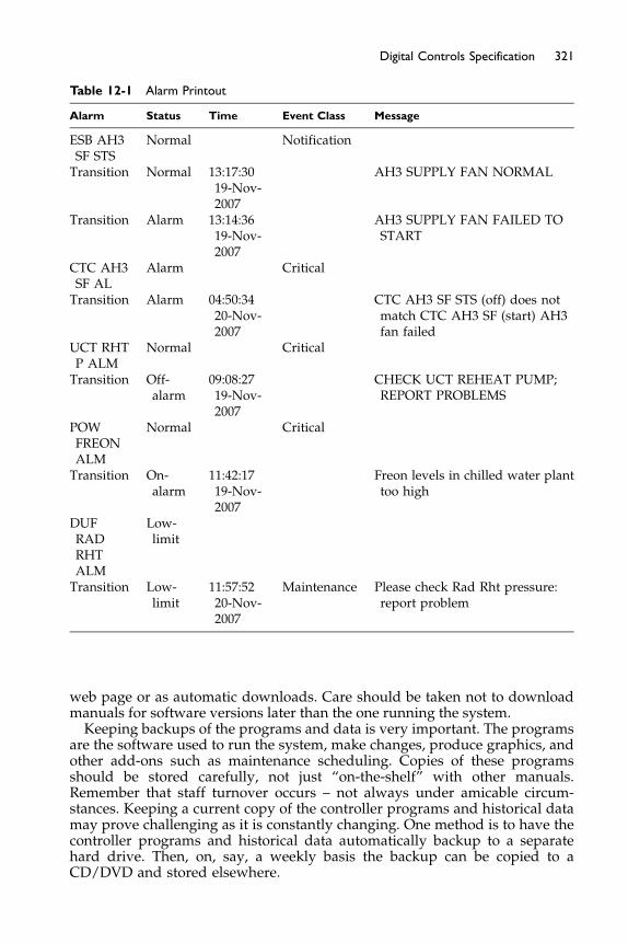
Table 12-1 Alarm Printout
Alarm Status Time Event Class Message
ESB AH3SF STS
Normal Notification
Transition Normal 13:17:3019-Nov-2007
AH3 SUPPLY FAN NORMAL
Transition Alarm 13:14:3619-Nov-2007
AH3 SUPPLY FAN FAILED TOSTART
CTC AH3SF AL
Alarm Critical
Transition Alarm 04:50:3420-Nov-2007
CTC AH3 SF STS (off) does notmatch CTC AH3 SF (start) AH3fan failed
UCT RHTP ALM
Normal Critical
Transition Off-alarm
09:08:2719-Nov-2007
CHECK UCT REHEAT PUMP;REPORT PROBLEMS
POWFREONALM
Normal Critical
Transition On-alarm
11:42:1719-Nov-2007
Freon levels in chilled water planttoo high
DUFRADRHTALM
Low-limit
Transition Low-limit
11:57:5220-Nov-2007
Maintenance Please check Rad Rht pressure:report problem
321Digital Controls Specification
web page or as automatic downloads. Care should be taken not to downloadmanuals for software versions later than the one running the system.Keeping backups of the programs and data is very important. The programs
are the software used to run the system, make changes, produce graphics, andother add-ons such as maintenance scheduling. Copies of these programsshould be stored carefully, not just “on-the-shelf” with other manuals.Remember that staff turnover occurs – not always under amicable circum-stances. Keeping a current copy of the controller programs and historical datamay prove challenging as it is constantly changing. One method is to have thecontroller programs and historical data automatically backup to a separatehard drive. Then, on, say, a weekly basis the backup can be copied to aCD/DVD and stored elsewhere.

322 Fundamentals of HVAC Control Systems
The two questions relating to backups that need to be answered are: ifeverything is on one operator workstation and the hard drive fails how willthe system be restored? If there is a fire in the room with the operator work-station and backup hard drive, how will the system be restored? To ensurethat these two questions can be answered satisfactorily you could specify thatthe process for both situations be taught to the operating staff so that they candemonstrate the recovery process by doing it themselves. One client definedtheir requirement as follows:
Software, backup facilities, and permanent instructions shall be provided sothat on total loss of the operator workstation an equivalent new PC with Win-dows XP can be reloaded with all operating and design software, the previousday’s database, and all archived history. The newly loaded PC is to operatethe same as the lost machine.
Now, depending on whether it is a new system in a separate building or anaddition to an existing DDC system, the specification can be written. Manydesigners already have a specification and it is a matter of modifying it forthe specific project. If, however, the specification is to be written from scratch,then assistance should be sought. An obvious, and often used, source is acontrols vendor. Be aware that the sample will be written to suit the vendor’ssystem. This is not a criticism but it is a warning. Read it carefully and decidewhether the degree of specification suits what you require in this particularproject. It will likely be based on a particular control protocol. Is it the oneyou require or would others be acceptable, or even preferable? Is the wiringspecification overly restrictive, inadequate, or unsuitable, for other vendors?Does it suitably specify a point naming convention, spare point capacities,operator terminal features?
Two other sources are recommended. The first, already mentioned, is ASH-RAE Guideline 13-2007 Guideline to Specifying DDC Systems which includessample specification language for much of the specification. It is a great helpbut again read it carefully and decide what you want for your system.The Standard uses BACnet as its basis for control protocol. Is this what yourproject needs? It is somewhat brief in content on commissioning, warranty,and backup requirements so again, what do you want for your project?
The last suggested source is based on Guideline 13 and is an online sitewhich produces controls specifications for specific systems, https://www.ctrlspecbuilder.com/. One chooses the system type from the given choicesand then makes a series of choices about the system from a preset menu.The site is easy to use and produces schematics, in VISIO (and can beimported into AutoCAD), as well as specifications. This site is supported bya controls vendor but the controls specifications it produces are based onASHRAE Guideline 13 and do not contain any proprietary product specifica-tions. Go and experiment with it. To repeat the warning: this is another goodsource but do read through the specification it produces carefully, and makesure the specification works for your project, and modify it as needed.
If your DDC project must now, or in the future, operate with anothersystem, the issue of interoperability must be addressed. Including text suchas “must be BACnet compatible” or “must use the same operator terminal asthe existing system” does not help the bidders decide what to provide. Neitherdoes it help you decide whether what is provided does what you require.

323Digital Controls Specification
If connection to an existing system is required, discussion with potentialbidders can be extremely valuable for specifying a suitable solution. Whichbrings us to the next section on bidding and interoperability.
12.3 Bidding and Interoperability
Bidding processes are often constrained by the client and may also be con-strained by the funding organization. Find out these constraints before writingyour specification. Note that they may be formal, such as a state requirementthat open bidding is required for all state buildings. Requirements may alsobe unwritten and due to prior experience with a product or supplier. Ideally,the list of acceptable bidders for DDC should be decided with the client andincluded in the specification to avoid having to assess company capabilitiesand compatibilities under the time demands of the bidding process.Guideline 13 includes a list of issues that can be used to pre-screen vendors.
Prescreening should be done with the capabilities of the client’s operating andmaintenance staff in mind. With very competent staff resources, local supportfor the system may not be critical. On the other hand, if local support from thevendor is critical, bids for installation may also include maintenance contractoptions.On larger projects it may well be advisable to include one, or more, mem-
bers of the client’s staff in this decision process. A staff person from the main-tenance department can do a lot to increase the department’s commitment tomaking the project a success. Having a staff person from the purchasingdepartment involved during the selection process can provide valuable sup-port during the bidding process, as he or she will have some understandingof the choices around the DDC system being purchased. He or she may alsounderstand that lowest-first cost from the controls vendor is not always bestlong term value.If the DDC system is to use the business LAN, having a representative from
the IT department involved can also make for a smoother integration process.Start talking to the IT department really early on in the project. Do note thatdevice names and terminology are not consistent between the IT world andHVAC world! Having the parties describe what a device does can often lowerthe tensions, as terminology gets sorted out. Agreement is needed on who willbe responsible for network issues on the shared network. If there is a corpo-rate overhead cost distribution for the network, this needs to be within thebuilding prime cost and operation budgets. Remember the network must beup and running for the DDC system to work. If the system is down for anhour each week for IT backup reasons, this may be the reason for havinga separate network for at least priority parts of the HVAC system. As thequality of service matters much more in some places than others, these out-of-hours periods of downtime may not be significant or they may be critical.If possible, have these issues settled, or at least clearly identified, before facingvendors.The question of integration brings us back to the general issue of interop-
erability, the ability of parts of the DDC system to work together. If theproject is stand-alone HVAC and not expected to be changed or expanded
324 Fundamentals of HVAC Control Systems
then a single vendor system has only to work with major equipment such aschillers and boilers. If the system is to be connected to an existing system oris expected to be enlarged over time, interoperability merits careful consider-ation. Remember the basic issues around interoperability and the use ofopen protocols. The following are the positive ones:
� ability to use different vendors for different parts of the HVAC systemplus additions, and modifications
� integration with other applications such as access, elevators, lighting, andlife safety having a single operator interface for the entire system
� ability to share the organization business network cabling� investment protection through a longer system life, as parts can be
upgraded and replaced.
There are also some challenging issues to deal with even when an open pro-tocol is being used. Initial integration of the different systems is not plug-and-play, and specifications must be clear about which vendor is taking responsi-bility for initial overall operation. If the specification, as is typical, requiresfree software updates during the warranty period, responsibility for gettingthese installed and fully working should also be specifically specified forone vendor.
Once installed, maintenance of each vendor’s system is required. This maybe in-house, which will require additional staff training time, and additionalmaintenance tools and spare parts, or additional outside maintenance con-tracts. Note that the use of an open protocol does not mean that the samemaintenance tools will work for parts installed by different vendors. Manyvendors have designed their own ways of binding (interconnecting) Lon-Works devices on a network. As an example, Vendor A’s system tools maynot be able to add a LonWorks device to the Vendor B network. The deviceis not the problem, it is how it is programmed to work on the network. Unfor-tunately, the full cost and time implications of maintaining multiple vendorsystems is often seriously underestimated or ignored during the initialpurchase decision period.
When designing a new system, if it is to work with an existing system witha single operator workstation, the first issue to be resolved is what gatewaysthe existing system manufacturer has to other HVAC protocols. Since consid-erable data are likely to be passing at times, a high speed network protocolis also desirable. If none exists it is possible to get one developed for a largeproject but this route is prone to financial and time challenges. It may be betterto accept the two operator workstations until the existing system can bereplaced.
In the more usual situation, where at least one suitable gateway is manufac-tured, the next issue is which of the available protocols will be most suitablefor the new system. If the system is to include connection to access, lighting,and fire/safety systems, this may be a challenge. Unfortunately, each industryis in the same situation as the HVAC industry with many existing proprietaryprotocols and open protocols gradually coming into general use and availabil-ity. To overcome this challenge, many of the larger HVAC controls manufac-turers are forming alliances with access, lighting, and life safety systemmanufacturers to provide an integrated package.

325Digital Controls Specification
Having resolved the issue of protocols at the system level, there is still theissue of protocols in the HVAC sub-networks. If the installed system is likelyto be relatively static, proprietary sub-networks can be used. However, ifsignificant changes or additions are likely it can be beneficial to require thesystem protocol to be used for sub-networks. The following is a simple exam-ple. Due to budget restrictions, several variable speed drives have been cutfrom the project. The client has asked for the controls point capacity and forthe cabling to be arranged so that they could be installed at a later date. If aproprietary sub-network is installed the choice of variable speed drive maybe limited when the funds are available to install them. If, instead, the systemprotocol had been required, this limitation would have been largely avoided.
12.4 Monitoring
One of the most useful features of DDC systems is the ability to monitor whatis happening in the system. Seeing the system working and checking on per-formance is greatly assisted by recording, or trending, values of points at setintervals. For checking the performance of a control loop a short time interval,say 1 second, may be used. The minimum time interval and number ofrecords will typically be determined by the controller and its memory capac-ity. For ongoing monitoring of system performance, longer time intervals, say15 minutes, may be specified with the records being regularly uploaded andstored in the operator workstation. The points that are to be continuouslytrended to provide history should be identified in the points list.Trended data can also be used to asses the comparative performance of
the system over time and we will consider two examples: one for heatingand one for cooling. Both of these examples involve relatively simple record-ing, data manipulation, and display. However, unless they are set up as partof the initial contract they may well be beyond the desires and capabilities ofthe accounts and operating staff.Many building owners do not posses the staff competencies and incentives
to monitor utility use and costs. Typically, the utility bills are paid from a uti-lities account by accounts payable staff that have no idea how the utilitieswere used. The maintenance and operations department are expected tomaintain and operate the plant to everyone’s satisfaction, with no downtimeand an ever decreasing budget. With accounts payable lacking the ability,and the maintenance and operations lacking the incentive, it is no wonder thatmany organizations use, and thus pay for, more utilities than necessary.Our heating example answers the question: “Taking into account the
effects of weather, is this facility using more or less heating now than inthe past?” Heating loads for the building fabric and air are proportional tothe difference in temperature between inside and outside. If the temperaturedifference between inside and outside doubles, the conduction heat lossthrough walls, windows, and roofs will also double. Similarly, the heat neededto raise outside air to indoor conditions will double.The comparative effect of outside temperature changes can be estimated
reasonably accurately by a simple process, often called the “degree day”method. If the outside temperature is recorded every hour for the (24-hour)day, and the highest and lowest records averaged, one has a reasonable
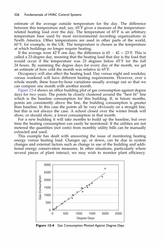
326 Fundamentals of HVAC Control Systems
estimate of the average outside temperature for the day. The differencebetween this temperature and, say, 65�F gives a measure of the temperature-related heating load over the day. The temperature of 65�F is an arbitrarytemperature base used by most environmental recording organizations inNorth America. Other temperatures are used in other parts of the world,60�F, for example, in the UK. The temperature is chosen as the temperatureat which buildings no longer require heating.
If the average were 42�F one day, the difference is 65 � 42 ¼ 23�F. This iscalled a 23-degree day, meaning that the heating load that day is the load thatwould occur if the temperature was 23 degrees below 65�F for the full24 hours. By summing the degree days for every day of the month, we getan estimate of how cold the month was relative to 65�F.
Occupancy will also affect the heating load. Day versus night and weekdayversus weekend will have different heating requirements. However, over awhole month, these hour-by-hour variations usually average out so that wecan compare one month with another month.
Figure 12-4 shows an office building plot of gas consumption against degreedays for two years. The points lie closely clustered around the “best fit” linewhich is the baseline consumption for this building. If, in future months,points are consistently above the line, the building consumption is greaterthan baseline. In this case the points all lie very obviously on a straight line,but this is not always the case. A school closed over the winter break willshow, or should show, a lower consumption in that month.
For a new building it will take months to build up the baseline, but overtime the heating consumption can easily be monitored. If the utilities are notmetered the quantities (not costs) from monthly utility bills can be manuallyextracted and used.
This example has dealt with answering the issue of monitoring heatingenergy versus heating load. Changes up, or down, can be due to systemchanges and external factors such as change in use of the building and addi-tional energy conservation measures. In other situations, particularly whereseveral pieces of plant interact, we may wish to monitor plant efficiency.
0
500
1000
1500
2000
2500
3000
0 500 1000 1500 2000 2500
Degree Days
Gas
Con
sum
ptio
n
Figure 12-4 Gas Consumption Plotted Against Degree Days

327Digital Controls Specification
As an example let us consider monitoring the performance of a chilled watersystem.Many larger sites have central chilled water systems. Research has found
that systems often run at well below anticipated performance and that thepoor performance is often not known by the operating staff. To improve thissituation it would be valuable to have the system report on chilled water plantperformance. A typical electrically driven chiller system consists of four maincomponents as shown in Figure 12-5.
� chilled water pumps to distribute the chilled water� chillers to cool the chilled water and reject heat to the condenser water� condenser water pumps to circulate the condenser water through the
chiller and cooling towers� cooling tower fans
The coefficient of performance of the plant is
useful cooling produced
chilled water plant power consumption
The coefficient of performance, COP, is dimensionless with the same unit onthe top and bottom of the equation, Btus or kW. Alternatively the performanceis often expressed in terms of kW input/ton of cooling output, kW/ton. A tonof cooling is 12,000 Btu/hr and a kWh is 3,412 Btu/hr. A good plant at peakefficiency may operate at 0.5 kW/ton.
COP ¼ 12; 000
0:5� 3; 413¼ 7
Note that both ways of reporting are considering energy use and not energycost. On plants which have storage, usually chilled water or ice storage,
CONDENSER
CONDENSER
EVAPORATOR
EVAPORATOR
kW
kWkW
kW
COOLING TOWERS CONDENSERPUMPS CHILLERS
CHILLEDWATERPUMPS
kW
CHILLED WATER
TO LOADS
CHILLED WATER
FROM LOADS
kW
kW
kW
Figure 12–5 Chilled Water Plant, Power IN (kW) and Chiller Water Cooling OUT

328 Fundamentals of HVAC Control Systems
minimizing cost, not energy consumption, is an objective. The concept is thatit can be cost effective to use more low cost energy at night to produce andstore chilling for the following day than produce the chilling at time of need.Because the performance of the plant is more complex to record and to pres-ent is not covered here.
In designing a monitoring system, the first, and most important, issue todecide upon is “what is the objective?” If the objective is to monitor theCOP of the chilled water plant what information must be recorded (referringto Figure 12-5)? What has to be measured?
The obvious answer is all the kW inputs and the chilled water cooling –8kW meters and a Btu meter for the chilled water. Obviously, but not neces-sarily. If the distribution panel can be laid out to supply the chilled waterplant through a single metered cable or bus, as shown in Figure 12-6 all powercan be metered with a single meter. Perhaps the chillers are supplied at ahigher voltage than the pumps then the question is can the chillers be on a sin-gle supply and the pumps on a single supply, using two meters instead ofeight?
You may be wondering why one would consider meter consolidation whenhaving the 8 meters provides information on how each component is working,not just the whole plant. The issue is what your objective is and what is thecost of meeting that objective. Predictably, the more accurate the meter, thehigher the cost. If plant efficiency is the required information, then using justone input meter and one output meter only requires two accurate meters. Italso has the advantage of reliability, as failure of either meter produces anobviously incorrect performance value.
Note that making choices about the metering will involve the electricaldesigner. One needs to think of the system as more than just the HVACcomponents.
CONDENSER
CONDENSER
EVAPORATOR
EVAPORATOR
kW
kWkW
kW
COOLING TOWERS CONDENSERPUMPS CHILLERS
CHILLEDWATERPUMPS
kW
CHILLED WATER
TO LOADS
CHILLED WATER
FROM LOADS
kW
kW
kW
Btu meter onchilled water
Meter electrical supply towhole system, kW
Figure 12-6 Chilled Water System with One Input Meter and One Output Meter
329Digital Controls Specification
What accuracy do we need? ASHRAE Guideline 22, yet to be published,suggests aiming at 5% overall accuracy. To achieve this we need to meterthe electrical power and chilled water Btu. An electric meter with accuracyof �1% is readily available, and �0.1% is quite practical. Btu measurementis more of a challenge. The Btus are calculated from chilled water flow rateand temperature difference. The flow rate measurement is going to be depen-dent on both the quality of the meter but also the installed situation. A lengthof straight pipe before and after the meter is needed to achieve even flow, andthis is often difficult to achieve. Note that it does not matter whether the flowmeter is in the supply or return pipe or whether it is in the confines of theplant space or in a distribution main, as long as it is measuring the full chilledwater flow. Be aware that factory calibration accuracy is rarely achived in thefield, even with careful field calibration. Typically, �2% accuracy can beachieved but �1% is difficult.Temperature measurement with a thermistor, calibrated over the narrow
range of chilled water temperature (38–60�F), can provide an end-to-end(thermistor, transducer, controller) accuracy of 0.1�F. The differential temper-ature is the difference between two temperatures so on a system with a 10�Fdifferential it is better than �2%, and close to �1% with a differential of 15�F.Combining accuracies to obtain an estimate of overall accuracy is beyond
this text, but with better than 1% on electricity, and better than 2% on flowand tempertaure diufference, the target of �5% can be met. Note that itrequires considerable diligence and effort to achieve these accuracies withstandard DDC control system components and the accuracy may drop seri-ously at lower loads. It can be beneficial to specify an energy managementpackage from a specialist supplier with the outputs being connected to theDDC system.On a system where we are measuring COP, how much energy is rejected
from the system by the cooling towers and how would you measure it?Putting a Btu meter on the condenser water circuit is one way. However,flow meters on condensing water flows are often inaccurate due to thepoor water quality. What heat is being rejected? The heat brought in by thechilled water and the heat put into the plant in the form of electrical energy,Figure 12-7, is the heat being rejected. There is no need to meter the heatrejection unless one is using it as a check on the COP input measurements.For detailed information on assessing the efficiency of chilled water plants,
refer to the proposed ASHRAE Guideline 22, Instrumentation for MonitoringCentral Chilled Water Plant Efficiency. This standard dicusses the desing ofchilled water systems and their metering, as well as providing example speci-fication language.Two useful resources for comparing building heating and cooling energy
usage are ASHRAE Standard 105-2007 Standard Methods of Measuring,Expressing and Comparing Building Energy Performance and the US EPAPortfolio Manger. The standard provides standardized forms for data collec-tion and comparison along with helpful conversions and energy values forfuels. The EPA Portfolio Manager provides US organizations with an easy-to-use online software that can provide comparative performance assessmentand data for many of the common building types.The systems performance and the success of these two metering examples
depend on measurement accuracy and reliable recoding over time.
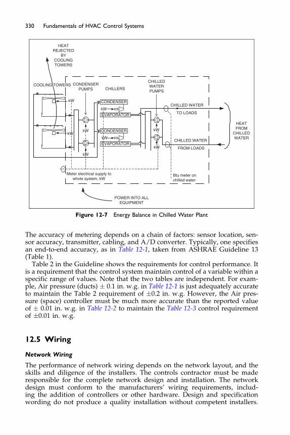
CONDENSER
CONDENSER
EVAPORATOR
kW
kWkW
kW
COOLING TOWERS CONDENSERPUMPS CHILLERS
CHILLEDWATERPUMPS
kW
CHILLED WATER
TO LOADS
CHILLED WATER
FROM LOADS
kW
kW
kW
Btu meter onchilled water
Meter electrical supply towhole system, kW
HEATFROM
CHILLEDWATER
POWER INTO ALLEQUIPMENT
HEATREJECTED
BYCOOLINGTOWERS
EVAPORATOR
Figure 12-7 Energy Balance in Chilled Water Plant
330 Fundamentals of HVAC Control Systems
The accuracy of metering depends on a chain of factors: sensor location, sen-sor accuracy, transmitter, cabling, and A/D converter. Typically, one specifiesan end-to-end accuracy, as in Table 12-1, taken from ASHRAE Guideline 13(Table 1).
Table 2 in the Guideline shows the requirements for control performance. Itis a requirement that the control system maintain control of a variable within aspecific range of values. Note that the two tables are independent. For exam-ple, Air pressure (ducts) � 0.1 in. w.g. in Table 12-1 is just adequately accurateto maintain the Table 2 requirement of �0.2 in. w.g. However, the Air pres-sure (space) controller must be much more accurate than the reported valueof � 0.01 in. w.g. in Table 12-2 to maintain the Table 12-3 control requirementof �0.01 in. w.g.
12.5 Wiring
Network Wiring
The performance of network wiring depends on the network layout, and theskills and diligence of the installers. The controls contractor must be maderesponsible for the complete network design and installation. The networkdesign must conform to the manufacturers’ wiring requirements, includ-ing the addition of controllers or other hardware. Design and specificationwording do not produce a quality installation without competent installers.
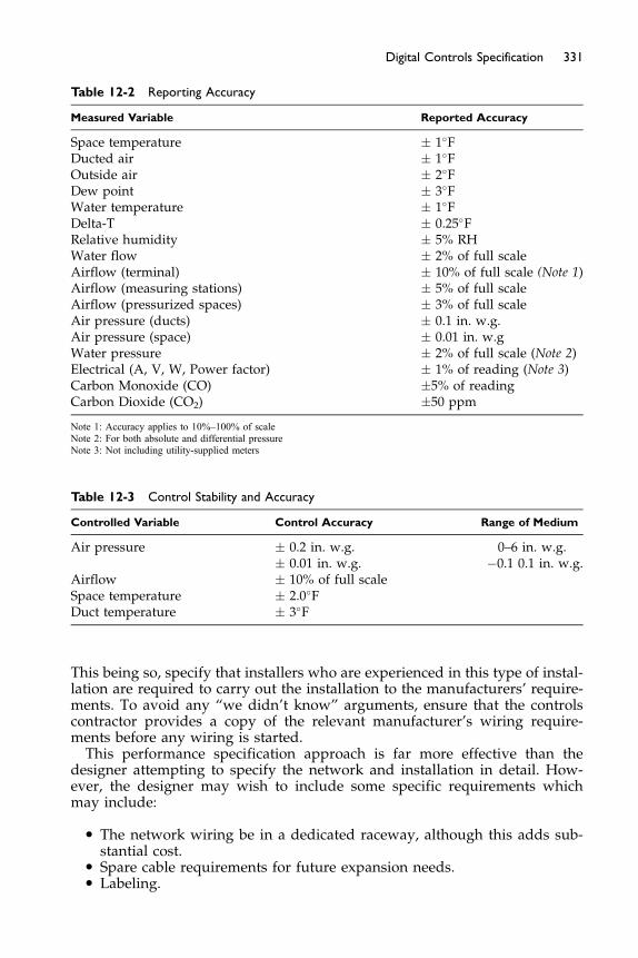
Table 12-2 Reporting Accuracy
Measured Variable Reported Accuracy
Space temperature � 1�FDucted air � 1�FOutside air � 2�FDew point � 3�FWater temperature � 1�FDelta-T � 0.25�FRelative humidity � 5% RHWater flow � 2% of full scaleAirflow (terminal) � 10% of full scale (Note 1)Airflow (measuring stations) � 5% of full scaleAirflow (pressurized spaces) � 3% of full scaleAir pressure (ducts) � 0.1 in. w.g.Air pressure (space) � 0.01 in. w.gWater pressure � 2% of full scale (Note 2)Electrical (A, V, W, Power factor) � 1% of reading (Note 3)Carbon Monoxide (CO) �5% of readingCarbon Dioxide (CO2) �50 ppm
Note 1: Accuracy applies to 10%–100% of scaleNote 2: For both absolute and differential pressureNote 3: Not including utility-supplied meters
Table 12-3 Control Stability and Accuracy
Controlled Variable Control Accuracy Range of Medium
Air pressure � 0.2 in. w.g.� 0.01 in. w.g.
0–6 in. w.g.�0.1 0.1 in. w.g.
Airflow � 10% of full scaleSpace temperature � 2.0�FDuct temperature � 3�F
331Digital Controls Specification
This being so, specify that installers who are experienced in this type of instal-lation are required to carry out the installation to the manufacturers’ require-ments. To avoid any “we didn’t know” arguments, ensure that the controlscontractor provides a copy of the relevant manufacturer’s wiring require-ments before any wiring is started.This performance specification approach is far more effective than the
designer attempting to specify the network and installation in detail. How-ever, the designer may wish to include some specific requirements whichmay include:
� The network wiring be in a dedicated raceway, although this adds sub-stantial cost.
� Spare cable requirements for future expansion needs.� Labeling.
332 Fundamentals of HVAC Control Systems
Effective labeling makes checking the initial installation and maintenancemuch easier and reduces mistakes. DDC sensors often terminate with twowires in an electrical box. When two sensors are side-by-side on an air-handling unit they both look the same. The boxes and wiring should belabeled. Although self-adhesive labels look more professional, the pointnames in permanent marker will still be there when the adhesive has failed.
Many control systems will have more than one network type. Typically, ahigh speed Ethernet with slower sub-networks. Specifications for both net-work types are required, and more experienced installers are needed for thehigh speed network. Be very clear about responsibilities, where the controlsare to use the site LAN, and what testing and verification may have to be doneto satisfy the in-house IT department.
Be aware of distance restrictions since, depending on the wiring configura-tions, the use of a signal booster repeater, may be necessary to maintainreliable signal strength.
Shielded wire may be used to limit the induction of noise onto the system’sconductors. Manufacturers of control systems may or may not recommend itsuse. Some systems only require the shielding for communication wiring.When connecting the shield to ground it is generally desirable to only connectone end of the shield to its grounding source, and leave the other end notconnected. It also should be noted that shielding can affect allowable wiringdistances and installed cost.
Underground cabling can offer many other problems. First, the pulling ofthe cables into the underground conduit can be dangerous to the integrity ofthe network. The tension created by the installers can stretch the wire andcause the #18 AWG wire to become anywhere between a #18 AWG to a #24AWG wire in the middle or at the ends, not to mention the obvious possibilityof breakage of the wire totally. For this situation, using an “assisting pullwire” such as a #12 AWG for long pulls and wrap the network wiring aroundthe assisting wire can relieve most of the tension.
Long underground pulls can create nicks or tears in the insulation, causingshorts and intermittent communication problems. Also, underground conduitwill eventually get water in it. In any case, wet wire can mean a nightmare tothe control system operator. All of a sudden the “no communication” lightcomes on and does not go off. Wire insulations can also be important; makesure the wire you are using is recommended for use in damp or wet locations.In general, the wire you would use in the ceilings, such as plenum or plasticjacketed, will not be appropriate for use underground.
When installing thermostats and wall mounted devices, it is recom-mended that an appropriate rough-in plate be used that will rigidly connectthe plate to the structure and not allow movement. Furthermore, all surfacesshould be kept level, and as close to fitting tolerances as possible. Cuttingand patching should be kept to a minimum. The use of Molly bolts ordrywall anchors for attaching wall devices is not acceptable for long-termreliability.
Air migrating from one part of the building to another may flow into theback of a thermostat, causing an incorrect temperature to be sensed. Depend-ing on the height of the building, construction, and location, it may be wiseto specify that the wall hole behind all thermostats be sealed against airleakage.
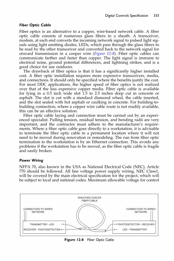
333Digital Controls Specification
Fiber Optic Cable
Fiber optics is an alternative to a copper, wire-based network cable. A fiberoptic cable consists of numerous glass fibers in a sheath. A transceiver,modem, at each end converts the incoming network signal to pulsed light sig-nals using light emitting diodes, LEDs, which pass through the glass fibers tobe read by the other transceiver and converted back to the network signal foronward transmission in a cooper wire (Figure 12-8). Fiber optic cables cancommunicate farther and faster than copper. The light signal is immune toelectrical noise, ground potential differences, and lightning strikes, and is agood choice for use outdoors.The drawback of fiber optics is that it has a significantly higher installed
cost. A fiber optic installation requires more expensive transceivers, media,and connections. It should only be specified where the benefits justify the cost.For most DDC applications, the higher speed of fiber optics is not realizedover that of the less expensive copper media. Fiber optic cable is availablefor lying in a 0.5 inch wide slot 1.5 to 2.5 inches deep cut in concrete orasphalt. The slot is cut with a standard diamond wheel, the cable inserted,and the slot sealed with hot asphalt or caulking in concrete. For building-to-building connection, where a copper wire cable route is not readily available,this can be an effective solution.Fiber optic cable laying and connection must be carried out by an experi-
enced specialist. Pulling tension, residual tension, and bending radii are veryimportant, and the contractor must adhere to the manufacturer’s require-ments. Where a fiber optic cable goes directly to a workstation, it is advisableto terminate the fiber optic cable in a permanent location where it will notneed to be moved during renovation or remodeling. The run from fiber optictermination to the workstation is by an Ethernet connection. This avoids anyproblems if the workstation has to be moved, as the fiber optic cable is fragileand easily broken.
Power Wiring
NFPA 70, also known in the USA as National Electrical Code (NEC), Article770 should be followed. All line voltage power supply wiring, NEC Class1,will be covered by the main electrical specification for the project, which willbe subject to local and national codes. Maximum allowable voltage for control
TRANSMITTER - LED
RECEIVER - PHOTODETECTOR
PHOTODETECTOR - RECEIVER
LED - TRANSMITTER
SHEATHED DUPLEXFIBER CABLE
CONNECTION TO WIREDNETWORK
CONNECTION TO WIREDNETWORK
Figure 12-8 Fiber Optic Cable
334 Fundamentals of HVAC Control Systems
wiring shall be the local user socket outlet voltage, 120 volts in NorthAmerica, and 110 up to 240 volts in other parts of the world.
In general, power wiring should not be installed in the same relative area orraceway as the network wiring. A few guidelines below cover recommendedinstallation practices:
� All low-voltage wiring shall meet NEC Class 2 requirements. Low-voltagepower circuits shall be sub-fused when required to meet Class 2 currentlimit. (NEC Class 2 wiring is the circuit to a final device).
� Where NEC Class 2, current-limited, wires are in concealed and accessi-ble locations, including ceiling return air plenums, approved cables notin raceway may be used provided that cables are UL/ CSA/ ETL orother code listed for the intended application. For example, cables usedin ceiling plenums shall be listed specifically for that purpose.
� Do not install low voltage Class 2 wiring in raceway containing powerClass 1 wiring. Boxes and panels containing high voltage wiring (90 voltsand above) and equipment may not be used for low voltage wiring (89volts and below), except for the purpose of interfacing the two such asfor relays and transformers.
� Where plenum cables are used without raceway, they shall be sup-ported from or anchored to structural members. Cables shall not besupported by or anchored to ductwork, electrical raceways, piping, orceiling suspension systems.
� All wire-to-device connections shall be made at a screw-type terminalblock or terminal strip. All wire-to-wire connections shall be at a termi-nal block. Note that wire nuts, soldered, and crimped connections shouldbe avoided as they system testing and maintenance difficult.
� All wiring shall be installed as continuous lengths, with no splicespermitted between termination points.
� Install plenum wiring in sleeves where it passes through walls and floors.Maintain fire rating at all penetrations using UL rated products.
� Use coded conductors throughout with conductors of different colors.� Control and status relays are to be located in designated enclosures only.
These enclosures include packaged equipment control panel enclosuresunless they also contain Class 1 starters.
� The contractor shall terminate all control and/or interlock wiring andshall maintain updated, as-built, wiring diagrams with terminationsidentified at the job site.
� Post-installation residual cable tension shall bewithin cablemanufacturer’sspecifications.
12.6 Commissioning and Warranty
Commissioning Process: a quality focused process for enhancing the deliveryof a project. The process focuses upon verifying and documenting that thefacility and all of its systems and assemblies are planned, designed, installed,tested, operated, and maintained to meet the Owner’s Project Requirements(ASHRAE Guideline 0 The Commissioning Process).
335Digital Controls Specification
Other definitions specifically require the provision of the system documen-tation and training being provided to the facility staff. Good commissioninggoes much further than the HVAC systems contractor making the systemwork. Commissioning ideally starts with the commissioning agent makingsure it understands the intent of the controls and their logic. During construc-tion and on completion, random checks are carried out to detect any system-atic errors and specific checks on control logic are also carried out. Finally, thecommissioning agent ensures that the staff training is properly completed anddocumentation provided.With the increasing complexity of modern buildings, and particularly the
integration of lighting and other controls, commissioning is becoming evenmore important and valuable. Commissioning is an added cost to the initialproject. Commissioning reduces the initial occupancy costs and disruptionsas well as reducing ongoing utility costs. For some clients, minimizing occu-pant dissatisfaction can be more valuable than accountable financial savings,so the cost is secondary. Unfortunately, the initial cost and ongoing costs areseparately accounted for in many organizations and it can be difficult to con-vince the client of the value of commissioning. The financial benefits are welldocumented in The Cost-Effectiveness of Commercial-Buildings Commissioning,a cost-effectiveness study of over 200 commercial buildings, by the LawrenceBerkeley National Laboratory. They found the savings often paid for thecommissioning in the first year. The web site with access to the complete textis given towards the end of this chapter, in “Resources’.Occupant satisfaction is often dependent on how quickly a problem is
resolved, which brings us to the issue of warranties. How quickly must thecontractor respond to a problem during working hours and during off hours?What personnel and replacement parts must be available locally or in a statedtime? This will vary depending on the project size and location. For remotelocations, having dial up or internet access to the system can be very usefulin helping the contractor send the correct spare parts with the servicepersonnel.Manufacturers update their software to deal with errors and also to make
significant performance changes. Some designers require that the installerinstalls any software updates as they become available during the warrantyperiod. This is good in that the client has the latest version, but it can havesome unexpected consequences. On one project the load shedding softwarewas changed, so the update did not run the load shedding correctly. Theinstaller and client did not realize the change until the next electrical billwas more than double what it would have been if the load shedding hadcontinued. In another case, the historical data collection software was changedand the history became inaccessible. Be careful, a good working system is notnecessarily better having updated software installed.Warranty periods are typically one year from demonstration that the system
is in complete working order. This is even if the occupants have been receiv-ing partial, or full, use from the system. Most electronic failures occur in thefirst year and an extended warranty is generally not economic as a warrantyfor component failure.Many specifications include a provision that the manufacturer continue to
have replacement components available for five years from completion. Thiswarranty requirement does not necessarily include the replacement, only that
336 Fundamentals of HVAC Control Systems
they are available. Since there is no financial provision in the contract forthis requirement, it is difficult to enforce unless the contract is covered by aperformance bond. A performance bond is issued by an insurance company,typically, to guarantee the completion of a project but it may also be requiredto cover the extended warranty period.
12.7 Resources
The most valuable resource is the manufacturers. They know their productsand want them used successfully. Ask questions and go on asking until youunderstand. Manufacturers have their own names for things that you maynot recognize: ask them to explain. Remember that a contract that runssmoothly without any nasty surprises is best for everyone. Many organizationsand manufacturers’ web sites have very good technical literature available toview and download.
The following are some specific web site suggestions to help you getstarted. They are no particular order.
BACnet International is the association of those interested in the use andpromotion of BACnet: http://www.bacnetassociation.org
CtrlSpecBuilder.com is a free site for generating DDC specifications anddrawings for common HVAC systems: http://www.ctrlspecbuilder.com/
Automated Buildings’ web site has both information and many useful links:http://www.automatedbuildings.com
LonMark International is the organization devoted to the use and develop-ment of LonWorks. Both general introductory and detailed technical informa-tion is available on their site: http://www.lonmark.org
The Continental Automated Buildings Association focuses on buildingautomation with significant focus on residences: http://www.caba.org
EPA Portfolio Manager is an USA program designed to provide compara-tive energy use information about most types of commercial buildings andinformation, available at: http://www.energystar.gov/index.cfm?c=evaluate_performance.bus_portfoliomanager
Whole Building Diagnostician (WBD) software field test evaluation,available at http://www.buildingsystemsprogram.pnl.gov/fdd/publications/PNNL-39693.pdf
The Cost-Effectiveness of Commercial-Buildings Commissioning, Evan Mills,Lawrence Berkeley National Laboratory, 2004, is a report on a large investiga-tion into the value of commissioning commercial buildings. The full text isavailable at: http://eetd.lbl.gov/emills/PUBS/Cx-Costs-Benefits.html
The following are specifically relevant, for purchase, documents that arementioned in the text:
National Electrical Code NFPA 70: 2008 is the latest rules for electrical instal-lation in residential, commercial, and industrial occupancies in the USA:http://www.nfpa.org
ASHRAE Guideline 0 – The Commissioning Process 2005. The purpose of thisguideline is to describe the Commissioning Process capable of verifying thatthe facility and its systems meet the owner’s project requirements. The proce-dures, methods, and documentation requirements in this guideline describe
337Digital Controls Specification
each phase of the project delivery and the associated commissioning processesfrom pre-design through occupancy and operation, without regard to specificelements, assemblies, or systems: http:/www.ASHRAE.orgASHRAE Guideline 1- The HVAC Commissioning Process 1996 – The pro-
cedures, methods, and documentation requirements in this guideline covereach phase of the commissioning process for all types and sizes of HVAC sys-tems, from pre-design through final acceptance and post-occupancy, includ-ing changes in building and occupancy requirements after initial occupancy.The guideline provides procedures for the preparation of documentation ofthe owner’s assumptions and requirements; design intent, basis of design,and expected performance; verification and functional performance testing;and operation and maintenance criteria. This guideline includes a programfor training of operation andmaintenance personnel: http:/www.ASHRAE.orgASHRAE GPC-13-2007 Guideline to Specifying DDC Systems. The purpose of
this guideline is to provide recommendations for developing specifications fordirect digital control (DDC) systems in heating, ventilating, and air-conditioning(HVAC) control applications. The guideline includes discussion of options andsample specification language: www.ashrae.org (product code 86823).ASHRAE Guideline 14-2002 Energy Management, Energy Savings. This docu-
ment provides guidelines for reliably measuring energy and demand savingsof commercial equipment. Energy service companies (ESCOs), ESCO custo-mers, utilities and others can use these measurements before the sale or leaseof energy-efficient equipment to determine post-transaction savings. Thesemeasurements can also be used to document energy savings for various creditprograms, such as emission reduction credits associated with energy efficiencyactivities.ASHRAE Standard 105-2007 Standard Methods of Measuring, Expressing and
Comparing Building Energy Performance. This standard is intended to foster acommonality in reporting the energy performance of existing or proposedbuildings to facilitate comparison, design and operation improvements, anddevelopment of building energy performance standards. It provides a consis-tent method of measuring, expressing, and comparing the energy perfor-mance of buildings. This latest revision provides a method of energyperformance comparison that can be used for any building, proposed or exist-ing, and that allows different methods of energy analysis to be compared.ASHRAE – Standard 135-2004, BACnetW – A Data Communication Protocol for
Building Automation and Control Networks Systems (ANSI approved), availablefrom ASHRAE Bookstore at http://www.ashrae.org bookstore (product code86449). It is also ISO 16484-5:2003 Building automation and control systems– Part 5: Data communication protocol, available from the International Orga-nization for Standardization, Geneva 20, Switzerland: http://www.iso.orgThe purpose of this standard is to define data communication services and
protocols for computer equipment used for monitoring and control ofHVAC&R and other building systems, and to define an abstract, object-oriented representation of information communicated between such equip-ment, thereby facilitating the application and use of digital control technologyin buildings. Note that this is a very, very technical standard and not easyreading, as it is dealing with computer programming. To get started withunderstanding BACnet in any detail go to the site for the committee thatproduces the BACnet Standard: http://www.bacnet.org

338 Fundamentals of HVAC Control Systems
Bibliography
Alerton Controls (2004) Use of Controller in DPAC Application. Redmond, WA, www.alerton.com.
ASHRAE Guideline 13-2000 – Specifying Direct Digital Control Systems, ASHRAE,Atlanta, GA. June 2000 þ Addenda 2005.
ASHRAE Standard 180 (2006) Standard Practice for Inspection and Maintenance of HVACSystems. Atlanta, GA.
Bailey, H. (2005) Fungal Contamination: A Manual for Investigation, Remediation, and Con-trol. Jupiter, FL: BECi.
BBJ Environmental Solutions, Baker, R. (2005) “Coil cleaning and its resultant eenergysavings and maintenance enhancements,” FWC ASHRAE newsletter, Tampa,November.
Behnken, J. (2001) “Building Automation for Multisite Facilities,” ASHRAE Journal,June, p. 53.
Brambley, M., Chassin, D., Gowri, K., Kammers, B., Branson, D., (2000) “DDC and theWEB,” ASHRAE Journal, December, p. 38.
Chapman, R. (2001) “How interoperability saves money,” ASHRAE Journal, February,p. 44.
Fisher, D. (2000) “BACnet at work,” ASHRAE Journal, July, p. 34.Hahn, W. and Michael, P.E. (1999) “Fast track HVAC conversion,” ASHRAE Journal,
December, p. 44.Honeywell HB&C, Automation and Control Specialist and LCBS CD-Rom. Minnea-
polis, MN.Hegberg, M. (1996) “MCH4 Controllers – HVAC-1 Class Presentation,” CD-Rom.Hydeman, M., Seidl, R. and Shalley, C. (2005) “Data center commissioning,” ASHRAE
Journal, April, p. 60.Invensys Inc. (2002–4) DDC Systems Information. Rockford, IL.Johnson Controls Inc. (2002–4) Control Systems Information. Milwaukee, WS.Otto, K. (2001) “Maximizing the value of open systems,” ASHRAE Journal, May, p. 33.Persily, A. (2002) “New Requirements of Standard 62-2001,” ASHRAE IAQ Applications,
Fall, p. 8.Seem, J., House, J. and Monroe, R. (1999) “On-line monitoring and fault detection,”
ASHRAE Journal, July, p. 21.Schulte, R. Bridges, B. and Grimsrud, D. (2005) “Continuous IAQmonitoring,” ASHRAE
Journal, May, p. 38.Shadpour, F. and Willis, L.P.E. (2001) “DDC systems as a tool for commissioning,”
ASHRAE Journal, November, p. 43.Wilkinson, R.J. (2002) Commissioning and Controls. HPAC Engineering: Cleveland, OH.Wiggins, S.R. (2005) “Retrocommissoning,” ASHRAE Journal, March. p. 76.

Index
AAcross-the-line magnetic motor
starter, 46–47Adjustable speed drives (ASDs).
See Variable speed drives (VSDs)Air-conditioning plant, 117–118, 217Air dryers, 197Airflow-measuring device, 238Air flow measuring station (FMS), 146Airfoil dampers, 87–88Air handling unit (AHU), 226–228,
237–238, 266–267Air-heating system, 5–6Air temperature, 234Air valve, 164–165Alternating current (AC) circuitscapacitor, DC circuit, 36circuit diagram, 35–36definition, 35impedance, 38inductor, DC circuit, 37–38magnetic field, 36–37power equation, three-phase
circuit, 39power factor, 38–39
Analog control. See Modulating controlAnalog electronic controlsactuator, 211–212auxiliary devices, 212economizer enthalpy control, 210idealized operational amplifier
(Op-amp), 206–207integral and derivative Op-amp, 208proportional Op-amp, 207sensor, 206single-zone unit controllers, 210
summing and subtractionOp-amp, 208–209
VAV box, 211Analog to digital (A/D)
converter, 255–256AND-gate, 266AnnubarW flow sensors, 139–140ANSI/ASHRAE Standard 135-2004, 302Application software, 260–261, 268Application-specific programming, 261,
268ARCNET standards, 299Artificial intelligence, 23ASHRAE Standard 62.1, 241–242,
245–246Aspirated (fan powered)
psychrometers, 132–133Authority distortion, 83–84Automatic control, 2–3Auxiliary devices, 178–179, 212
CO2 and indoor air quality(IAQ), 156–157
discriminator relay, 191–192electric and pneumatic transducer, 158electric/pneumatic switch
application, 194–195fan and pump status switches, 149–151fire and smoke detectors, 154–155fluid level device, 158–159indicating light and audible alarm, 155IP transducer–bleed type, 195isolation room pressure, 156limit and manual switches, 152low/high limit switches, 153–154manual pneumatic switch, 195–196manual rotary switch, 152–153
340 Index
Auxiliary devices (Continued)monitoring, 155multiplexer, 156–157pneumatic-electric relay, 194–195pneumatic switch, 192–193reversing relay, 191–192sequencing control, 191timeclocks, 151–152two pressures relay, 190–191vibration sensing, 156wind-up timers, 152
BBack-electromotive force (EMF), 37–38Balanced valves. See Double-seated
globe-type control valvesBalancing dampers. See Volume dampersBall valves, 68–70Barometric backdraft damper, 102Bernoulli’s equation, 137Bidding process, 321Bimetallic sensors, 109–110, 182–183Bimetallic strip, 3Binary numbers, 255Bleed-type controller, 182Boolean logiccontrol sequence, 54double-throw contact, 54–55three-way light switch, 55
Bourdon tubeelectric differential pressure
sensors, 168mechanical pressure gauges, 133–134
Building automation and controlnetworks (BACnet)
ANSI/ASHRAE Standard135-2004, 302
data communication protocol, 301–302DDC system design, 322devices, 303–304information protocol types, 302ISO Standard 16484, 301network, request and response
transportion, 306–308objects, 304–305protocol implementation conformance
statement (PICS), 303services, 305–306
Building static pressure control, 231–232
Butterfly valves, 68–69Bypass logic, 269, 271
CCapacitive sensor, 135Capacitor, 36Capacity control dutycapacity control applications, 96–98damper relative size factor, 96damper situation factor, 96–97discharge and inlet vane dampers, 93manufacturer factor, 94–96opposed blade damper, 93–95, 97parallel blade damper, 93–94, 97valve authority, 94volume damper, 92–93
Capillary sensors, 111–112Carbon dioxide (CO2) control, 241–242Chilled-mirror dew-point
sensors, 130–131Chilled water plant, energy
balance, 329–330Clock synchronization, 269Closed-loop control systems, 6Close-off pressuredouble-and single-seated valves, 87dynamic close-off rating, 85pump shut-off head, 87two-and three-way valve systems, 86variable flow system, 86
Coefficient of performance (COP), 327,329
Commissioning process, 334–335Compressed air supplyoil-free carbon-ring, 197pressure reducing valve
(PRV), 197–198Conductors, 31Constant air volume (CAV) systemface and bypass dampers, 226filter loading, variable speed
fan, 237–239multiple zones/reheat, 227regulators, 164
Control actions and normal positioncontrolled devices, 25–26direct acting (DA) and reverse acting
(RA), 24–25heating and cooling application, 27
341Index
proportional control logic, 24reversing relay, 27spring-return actuator, 26
Control damperscapacity control duty, 92–98damper linkages, 89–90damper motor, 89leakage reduction, 88–89mixing duty, 98–104multi-blade damper, 89–90operation styles and principles, 87triple V and airfoil blades, 87–88two-position duty, 91–92
Control diagrams and symbolscooling coil (CC), 218graphic symbol, 219heating coil (HC), 218
Control documentation, 28Controllersmodulating type
three-wire electric controlmotor, 173–174Wheatstone bridge circuit, 171–173
two-position typeelectronic timeclock/
thermostats, 171packaged unit, electric
control, 170–171stepping switch, 171–172two-position and floating electric
control, 169variable frequency drives (VFD), 170
Control logic, 250Control loopsautomobile vs. heating system, 5–6boiler reset control, 7closed-loop control system, 6controlled variable, 5open-loop control system, 7stat, 8
Control maintenance, 28Control modescontroller gain, 9–10definition, 9floating control, 14–15modulating control, 15–20pulse-width modulating (PWM)
control, 20–21system time constant, 9time-proportioning control, 21
two-position control, 10–14Control operations, 28Control point adjustment (CPA), 185Control range, 27–28Controls contractor, 218Control sequences, 28–29, 258–259
ABC temperature sensor and XYZcontroller, 220
air temperature control, 221control loops, 220–221performance specification
approach, 220wiring and installation methods, 222
Control systems design, 217–218Control valve selection and sizing
ball valve, 81butterfly valve, 80–81close-off pressure, 85–87coil subsystem, 77–78flow characteristic selection, 81–85oversized valve, 80rule-of-thumb, 78selection considerations, 76–77valve flow coefficient, 78–80
Cool anticipators (CA), 170–171Cooling coil pump, 232–233Cooling coil valve, 232Cooling tower plants, 239CO2 sensor, 239Cruise control system, 2Current switch, 149–150Cybernetic building system (CBS), 314
DDamper motor, 89Damper operator, 188–189Data communication protocol, 301–302Deadband thermostat, 186–187Demand limit control (DLC) routine, 276Digital control system, 23Digital gates, 265–267Direct-acting heating thermostat, 225Direct digital control (DDC) systems, 109
BACnet, 301–308bidding process, 323control sequences, 258–259cybernetic building system (CBS), 314fault detection, 313graphic display, 315input and output (I/O) points, 250–257
342 Index
Direct digital control (DDC) systems(Continued)
interoperability, 286–287LonWorksW, 308–310monitoring and maintenance, 315network standards, 296–301operation, peak efficiency, 312–313operator terminal, 278–284resources, 336–337software routines, 260–268specific programming system, 269–278system hardware architecture, 288–296tighter control, 313–314trend data, 314–315
Direct expansion (DX) systems, 246–247Discharge damper, 93Discriminator relay, 191–192Displacement flow meter, 147Diverting three-way valves, 72–76Doppler effect meter, 143Double-seated globe-type control valvescoil and control valve
characteristics, 67linear, equal percentage and flat plate
plug, 65–66plug lift, 66–67rangeability, 67
Duct-type smoke detector, 154
EEconomizerdampers, mixing process, 98, 101–104enthalpy control, 210variable air volume system, 233
Electrical potential, 160–161Electrical pressure guage, 135–136Electric motors and motor startersacross-the-line magnetic motor
starter, 46–47auxiliary contact, 49control power, 47definition, 45hand-off-auto (H-O-A) switch, 47–50in-rush current and overload
protection, 45–46life safety fan wiring, 50–51manual start/stop button, 49–50single-phase motor, 46start/stop control, 45
Electromagnetic interference (EMI), 38Electromagnetic relay, 42Electromotive force (EMF), 31Electronic timeclock/thermostats, 171EMF. See Electromotive forceEMI. See Electromagnetic interferenceEnthalpy sensor, 127–128Ethernetnetwork wiring, 332standards, 298–299
Evaporation process, 124–125Exhaust fan control, 242–243
FFace and bypass (F&B) damper, 225–226Feedback-control systems. See Closed-
loop control systemsFiber optic cable, 333Floating controlactuators, 177–178basics, 14–15
Flow sensors and metersair flow measuring station (FMS), 146air flow meter, 144–145AnnubarW, 139–140Bernoulli’s equation, 137displacement flow meter, 147inline turbine, 140–142orifice plate meter, 137–138paddle flow switch, 140–141passive flow meter, 142–143pitot tube equation, 139pitot tube sensor, 144–145propeller/rotating vane
anemometers, 147target/drag-force meter, 142thermal anemometer, 143–144venturi meters, 137–138
Fluid level devices, 158–159FMS. See Air flow measuring stationFreeze protection, 231Front-end computer, 320Fume hood control, 243–245Fuzzy logic, 23
GGains and loop tuningfuzzy logic, 23P, PI, and PID control loops, 21–23

343Index
self-tuning technique, 23Globe valve actuator, 70Graphical programming, 263–265Gravity dampers, 91–92
HHand-off-auto (H-O-A) switch, 47–50,
201–202Heat anticipators (HA), 170Heating coil valve, 232Heat transfer coefficient, 82High static pressure shutdown, 231Hot water control valve, 162Humidification processdry-bulb and wet-bulb
temperature, 125–126enthalpy sensor, 127–128evaporation process, 124–125water heating, 123–124
Humidifier control, 233Humidity sensors, 168Hydraulic actuator, 211Hygroscopic materials, 129
IIEEE 802.3 standards, 298–299Impedance, 38Indoor air quality (IAQ) sensing, 156–157Inductive sensor, 135–136Inlet vane damper, 93Input and output (I/O) pointsair heater with outdoor reset, 251analog input (AI), 254–255analog output (AO) and binary output
(BO), 257analog to digital (A/D)
converter, 255–256binary input (BI), 254–255binary numbers, 255control logic, 250DDC controller, 253end-to-end accuracy, 256old signal, 257types, 251–252
In-rush current, 46Insulators, 31Integrated circuit (IC), 116Interlock methodology, 242Interoperability, 323–325
IP transducer–bleed type, 195Isolation room pressure sensing, 156ISO Standard 16484, 301
LLadder diagrams
applications, 60control logic, 59–60rungs, 55–56symbols, 56voltage feedback bug, 57–58
Ladder-logic DDC system, 265–267Laminar flow, 81Lead–lag programming, 271–272Line-voltage thermostat, 169Lithium chloride dew-point
sensors, 129–130Logic control, 265LonBuilderW, 308–309LonMark Americas (LMA), 309LonMark International (LMI), 309LonTalk network protocol, 308–310LonWorksW
definition, 308LonMark device, 309–310Neuron chip, 308–309standard network variable types
(SNVT), 309transceiver, 308–309
MMagnehelic™ differential pressure
gauges, 246Magnetic flow meters, 143Manual rotary switch, 152–153Maximum differential pressure, 85–87Mercury switch, 4Mercury thermometer column, 3–4Mixing duty
barometric backdraft damper, 102constant volume application, 98–100relief/exhaust damper, 102–104stratification, 98variable air volume
application, 100–102Mixing three-way valves, 72–76Modulating control
continuously varying capacitycontrol, 16
344 Index
Modulating control (Continued)offset adjustment, 17proportional control, 16–19proportional plus integral (PI) control
logic, 17–20proportional plus integral plus
derivative (PID) controllogic, 17–18, 20
Moisture sensorschilled-mirror dew-point, 130–131lithium chloride dew-point, 129–130relative humidity, 128–129thin-film sensor, 129–130
Monitoringand control
chiller plant, pumps, andboilers, 239–240filtration and outside air, 246temperature and humidity, 240–241ventilation, 245
DDC systemschilled water plant, energy
balance, 329–330coefficient of performance
(COP), 327, 329gas consumption vs. degree day
method, 326trend data, 325
Motorized dampers, 91Multi-blade damper, 89–90Multiplexers, 156–157Multipole relays, 43–44Multi-zone model, 227
NNAND gate, 266–267Network standardsARCNET, 299Ethernet (IEEE 802.3), 298–299HVAC information protocol, 296–297network protocol, 297performance factors, 297–298RS–485, 299Wireless network, 299–301
Network wiring, 334controls contractor, 330Ethernet and underground
cabling, 332Neural networks, 23
Neuron chip, 308–309NodeBuilderW, 308–309Non-bleed controller, 181–182NOR gate, 266–267Normally closed (NC) port, 194Normally open (NO) port, 194
OOhm’s law, 171–172current, voltage, and resistance
relationship, 32electrical circuit diagram, 31electrical power, 34parallel circuit, 33series circuit, 33–34water tank analogy, 31–32
Oil-free carbon-ring compresser, 197On and Off delays. See Post and
pre-delaysOpen-loop control system, 7Operational amplifier (Op-amp)idealized, 206–207integral and derivative, 208proportional, 207summing and subtraction, 208–209
Operator terminalsalarms, 280–281LCD display, 278maintenance scheduling, 284password security, 283–284printer, 280system graphics, 279–280text mode system, 279trending, 281–283
OR-gate, 266Orifice plate meter, 137–138Outside air ventilation, 233Over-current protection, 45–46Overload protection, 45–46Overload relay, 45
PPaddle flow switch, 140–141Parallel circuits, 33Passive flow meter, 142–143PI. See Proportional plus integral control
logicPitot tube equation, 139Pitot tube sensor, 144–145
345Index
Pneumatic actuators, 212damper operator, 188–189hysteresis, 189positive (pilot) positioner, 190
Pneumatic controllerscontrol point adjustment (CPA), 185deadband thermostat, 186–187dual set point, 186proportional-plus integral (PI) control
logic, 184reversing (heating/cooling), dual
pressure, 187setback (day/night), dual
pressure, 187–188single set point, 185–186
Pneumatic logic diagrams, 198–199Pneumatic sensors, 183–184Pneumatic switch, 192–193Positive (pilot) positioner, 190Post and pre-delays, 275–276Power factor, 38–39Power wiring, 333–334Prefilter differential pressure
monitor, 233–234Pressure reducing valve (PRV), 166,
197–198Pressure sensorsbourdon tube, 133–134capacitive sensor, 135diaphragm, 134electrical pressure guage, 135–136inductive sensor, 135–136
Pressure static high limit (PSHL), 228Pressure sustaining valve, 165Pressure switch, 151Primary secondary pumping
system, 239–240Propeller/rotating vane
anemometers, 147Proportional (P) control, 16–19Proportional plus integral (PI) control
logic, 17–20, 184, 228Proportional plus integral plus
derivative (PID) control logic,17–18, 20
Protocol implementation conformancestatement (PICS), 303
Psychrometersaspirated (fan powered), 132–133sling, 132
Psychrometric chartheating process, 122–124indoor air, 118–119relative humidity, 119–122saturation point, 119
Pulse-width modulating (PWM)control, 20–21
RRefrigeration systems, 4Relative humidity, 119–122, 128–129,
240–241Relay logic. See Boolean logicRelays, 148–149, 212
DC circuit, 42–43definition, 42electromagnetic relay, 42multipole relay, 43–44normal position, 44single-and double-throw contacts, 44
Relay solenoid, 25Relief/exhaust damper, 102–104Repeatability, precision, 108Resistance temperature detectors
(RTD), 113, 115Return air damper, 101–104Reverse-acting cooling thermostat, 225Reversing relay, 191–192Reynold’s numbers, 137Rotary direct-coupled actuators, 177RS–485 networks, 299
SSelf-powered control
electrical potential, 160–161hot water control valve, 162thermopile control, gas
burner, 161–162Self-tuning techniques, 23Sensors
Bourdon tube/diaphragmtechnology, 168
humidity, 168temperature, 167–168
Sequencing control, 191Series circuits, 33–34Shut-off dampers, 88, 92Sine-coded pulse-width-modulation
(PWM), 52

346 Index
Single-seated globe-type control valvesnormally closed valve, 64normally open valve, 63–64service valves, 63water hammer, 65
Single zone electric control, 175Single zone pneumatic/electric
control, 198–200Single-zone systemair handler, 222–223controller deadband, 224duct smoke detector and freeze-
stat, 222face and bypass damper, 225–226heating/cooling control, 222–223hot water pre-heat coils/electric
heat, 224outdoor air damper, 223pneumatic thermostat, 224start/stop system, 222temperature control panel (TCP), 223
Single-zone unit controllers, 210, 212–213Sling psychrometers, 132Software routinesapplication software, 260–261application-specific programming, 268damper output, 260graphical programming, 263–265ladder-logic DDC system, 265–267off-line storage, 267text-based programming
language, 261–263Solenoid coils, 148–149Specific programming systembypass logic, 269, 271controller points, 271control loop, 272cooling, heating, and economizer
sequencing, 272cooling reset routine, 274–275DDC system, 277demand limit control (DLC)
routine, 276lead–lag programming, 271–272math function block diagram, 273minimum and maximum run
times, 275optimal start routine, 274, 276PI-control loop time graph, 272–273post and pre-delays, 275–276
power demand graph, 276–277pseudo/virtual points, 269, 271recovery and shut-down
routine, 274–275reset ramp graph, 274schedule components, 269–270trend data, 277–278
Split system, 246Spring-return actuator, 26Start–stop loops, 269Static pressure control, 202Stepping switch, 171–172Step-up and step-down transformer, 40Supply air duct static pressure
control, 231Supply air smoke detection, 231Supply air temperature, 234–235Symbols sampling, ASHRAE Standard
134–2005, 218–219System designair handler, 3-dimensional view, 318alarm, 320–321controller program, 321Ethernet, 317internet access, 319live demo testing software, 320overriding effect, 316point information, graphic
display, 319VAV box, graphics image, 318
System hardware architecturebridge function, 289building management systems (BMS)
hierarchy, 293–294initial DDC system layout, 288internet connection, 291–292layout, 293radio controller, 292router, 289–290sample controller, 295–298stand-alone panel, 293–295sub-network, 290telephone connection, modem, 291two-tiered and multi-tiered
communications, 295VAV box controller, 288–289wireless receiver, 292
System-powered controlair valve, 164–165water system valve, 165–166
347Index
TTemperature control panel (TCP), 223Temperature sensors, 167–168air-conditioning plant, 117–118bimetallic, 109–110capillary sensors, 111–112characteristics of, 116–117electrical, self-powered, 113integrated circuit (IC), 116linear diode, 116mercury switch, 110–111resistance temperature detector
(RTD), 113, 115–116rod-and-tube sensors, 111thermistor, 113–114thermocouple, 113
Text-based programminglanguages, 261–263
Thermal anemometer, 143–144Thermistors, 113–114Thermocouple, 113Thermopile control, gas burner, 161–162Thin-film sensor, 129–130Three-phase transformers, 40–41Three-way control valves, 26common and bottom port, 72–74linear and equal percentage plugs, 75normally open and closed ports, 72–75rangeability factor, 75–76
Three-wire electric controlmotor, 173–174
Throttling applications, 96–98Timeclockselectronic/programmable, 152mechanical, 151
Time-delay relay wiring, 149–150Time-proportioning control, 21Transformerscontrol system, 41–42definition, 39delta and wye connected 3-phase
transformer outputs, 40–41four-wire wye connected transformer
outputs, 41primary and secondary circuit, 39–40step-up and step-down transformer, 40
Transit time ultrasonic meters, 142–143Transmitters, 108–109, 203Triple V dampers, 87–88
Tri-state control. See Floating controlTurn-down ratio, 67, 75, 77Two-position control
differential, 11–12heating thermostat, 10–11operating differential, 12–13short-cycling, 13step control, 13–14
Two-way control valvesadvantages, 70–71ball valve, 68–70butterfly valve, 68–69disadvantages, 71–72double-seated globe-type valve, 65–68operation styles and principles, 62single-seated globe-type valve, 62–65
UUnderground cabling, 332
VValve flow coefficient
definition, 78–79pressure drop, 79–80
Variable air volume (VAV) system, 201AHU system, 227box controller, 288–289, 295, 297cascading control loop, 236control, 214–215controller signal, 230diffuser design and operation, 162–163direct digital control, 235duct pressure, 163economizer, 228–229indoor air quality, 230plain language, 231, 235pressure-dependant control, 236pressure static high limit (PSHL), 228proportional plus integral (PI)
control, 228reheat box function, 237relief/exhaust damper, 102reset schedule, 230static pressure control, 228supply air temperature control, 228temperature control, layout, 164volume control, 237
Variable frequency drives (VFD), 170Variable speed drives (VSDs)
348 Index
Variable speed drives (VSDs) (Continued)with bypass starter, 53–54definition, 51electronic bypass, 53sine-coded pulse-width-modulation
(PWM) waveform, 52variable frequency drive (VFD), 52–53
VAV. See Variable air volume systemVenturi meters, 137–138VFT. See Volumetric fan trackingVibration sensor, 156Volume dampers, 92–93Volumetric fan tracking (VFT), 102VSDs. See Variable speed drives
WWater hammer, 65Water source heat pumpsDX unit, 247heat pump unit, 248–249heat recovery system, 247–248
Water system valve, 165–166Wheatstone bridge circuit, 171–173Wind-up timers, 152Wireless network, 299–301
XXOR-gate, 266