Embed Size (px)
Citation preview

1
U.S. Particle Accelerator School
Fundamentals of Detector Physics
and Measurements Lab - IV
Carl Bromberg
Michigan State University
Dan Green
Fermilab
June 18-22, 2012
Outline
Lecture I
Constants, atoms, cross sections
Photoelectric, TOF
PMT, SiPM Scint, Cerenkov
Lecture II
Collisions, cross sections
Multiple scattering, radiation length
dE/dx, MIP, Range
Critical Energy
2
Outline II
Lecture III
B fields, trajectories
Quadrupoles, focal length
Drift and Diffusion
Pulse formation in unity gain and gas gain
Lecture IV
Radiation NR, Thompson, Compton
Relativistic radiation
Bremm, Pair Production
3

Si Vertex and b decays
4
~ / 2
~ / 2
a
T D
a
D
D a b
p M
p p
~ / ~1/
~ ( )
D D D
D
M p
b c
22
2
/22
/2
2
, 0
/
/
/12
P
P
y y y
y dy dy
y dy dy
P
HEP collider detectors have
“vertex detectors” which serve to
tag the production and decay of
heavy flavors. The “impact
parameter” b, is ~ the proper
decay length of the parent. The
spatial resolution should be << b.

b Tagging
5
US PAS, June 18-22, 2012
Impact parameter, decay length and mass of tracks at the
decay point are all possible tagging variables.
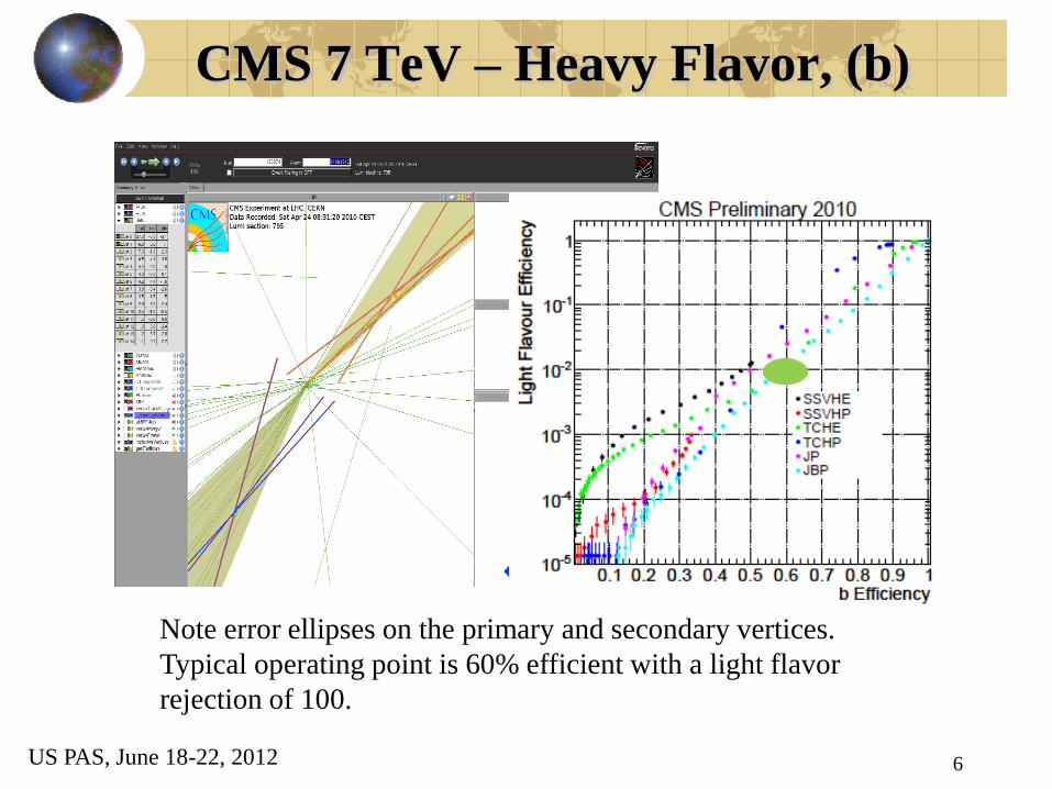
CMS 7 TeV – Heavy Flavor, (b)
Note error ellipses on the primary and secondary vertices.
Typical operating point is 60% efficient with a light flavor
rejection of 100.
6 US PAS, June 18-22, 2012

Intrinsic/Doped Si
7
12322 10~/,/1001.5~ siio
si nncmA
Nn
i
ii
KTii
cmknq
cmpn o
/1
200/1
/10300
311
~ 3.6
~ 300
~ /
~ 5 ~ 32,000
pair
s ion pair
s
E eV
d m
q q E E
q fC q
Intrinsic charge is due to thermal
excitation of a e-h pair. Since kT
~ 1/30 eV and Eg~ 3.6 eV this
charge is very small and intrinsic
Si has a high resistivity.
Therefore very low levels of
donor(n) and acceptor (p) states
can determine the resistivity and
the majority charge carriers
A typical detector has a MIP
signal of ~ 5 fC or ~ 32 thousand
e-h pairs in the VB-CB.
Si Energy Bands
8
CB (MT) n (e-)
VB(full) p(h)
-D
- A
Eg
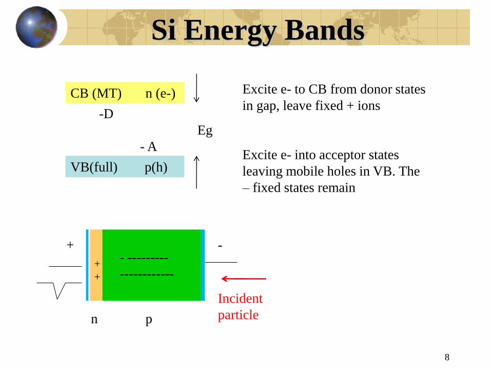
Excite e- to CB from donor states
in gap, leave fixed + ions
Excite e- into acceptor states
leaving mobile holes in VB. The
– fixed states remain
- + - ---------
------------ +
+
n p
Incident
particle

Si Diode
9
/
1
300 ,1
( ) 1
/ 25 o
qV kT
o
F K mA
I V I e
kTR dI dV
qI
“Dope” Si with a small
fraction of donor/acceptor
sites which are still >>
intrinsic conductivity. Form a
diode from a sandwich of n
and p type.
Io = reverse
current
(minority
carriers). V< 0
Forward bias, V
> 0 (majority
carriers)

Si Diode - II
10
DnAn DA Charge is conserved
[ ] / , ( )
D
E qn C C or CGS
CDxD
Anq
CDxnqxE
CAxnqxE
A
D
A
/)(
/)()0(
/)()0(
Applied voltage => depletion region.
Charge swept to electrodes. Static
charge remains, p type < 0, n type >
0.

Si Diode Fields - Depletion
11
2
2
( )( 0)
2
( )( ( 0) )
2
A
AD
E V
q n A x DV x
DC
q n x AV x V
C
2 22/ 2 , ,DV qp d C qp d MKS
potentials
2~ / 2D AV qn d C
d~A, fully depleted when
all free carriers are swept
to electrodes.
Derive V from E.
Just at depletion the
electric field is 0 at
the electrode
location
Si – Pulse Formation
12
2
/
2( )
( ) 1 , / ,
(0) 0, ( )
D
D
t
D
Vdx Edt x d dt
d
x t d e C qp
x x d
2
2 / 2 /
2
( ) / / ,
42 /D D
s D
t ts Ds D
I t dQ dt q E V
q Ve q e
d
2
( ) 2 /
( ) 0
/ 2
/ (0)
s D
D D
I o q
I
d V
d E
)240(710/~)(
sec)20(sec7~
5
nAnAqoI
nn
fCq
Ds
D
s
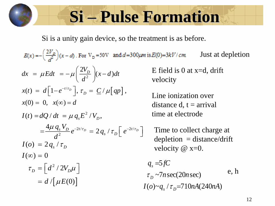
Si is a unity gain device, so the treatment is as before.
Just at depletion
E field is 0 at x=d, drift
velocity
Line ionization over
distance d, t = arrival
time at electrode
Time to collect charge at
depletion = distance/drift
velocity @ x=0.
e, h

Si Pixels
13
Present pixel generation = diode pixels bump bonded to readout chip.
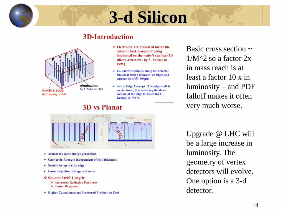
3-d Silicon
14
Basic cross section ~
1/M^2 so a factor 2x
in mass reach is at
least a factor 10 x in
luminosity – and PDF
falloff makes it often
very much worse.
Upgrade @ LHC will
be a large increase in
luminosity. The
geometry of vertex
detectors will evolve.
One option is a 3-d
detector.

Vertex Detectors
15
( ) 87
( ) ~ 475
( ) ~ (123,312) ( , )
b
o
c
c m
c m
c m D D
Pixel size scale set by
the lifetimes. PU is a
problem so that means
occupation of a pixel
must be small in order
to do robust tracking.
H->Z+Z->e+e+u+u
Tracking - Pixels and Strips
16
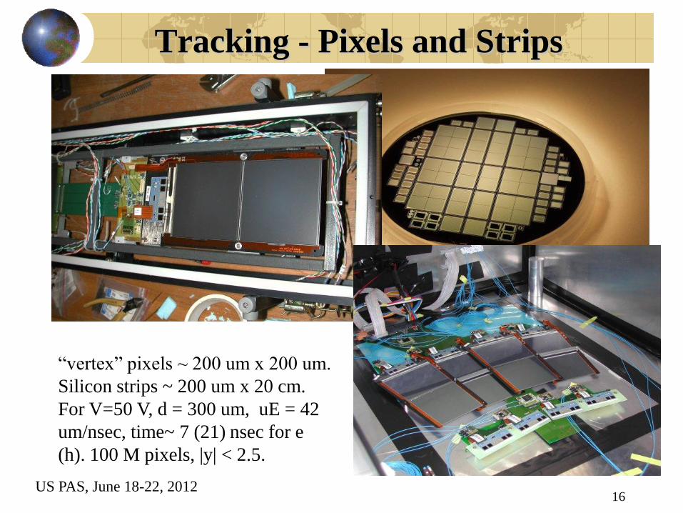
“vertex” pixels ~ 200 um x 200 um.
Silicon strips ~ 200 um x 20 cm.
For V=50 V, d = 300 um, uE = 42
um/nsec, time~ 7 (21) nsec for e
(h). 100 M pixels, |y| < 2.5.
US PAS, June 18-22, 2012

Readout -Noise – Reverse I
17
The reverse (minority carrier) diode leakage current is a strong
(exponential) function of T, exp(qV/kT). The scale is ~ nA.
Radiation damage makes defects => impurity states in the diode gap
=> enhanced leakage current. Run detectors at low T.
High resistivity, back biased Si
is ~ a current source.
Noise – Thermal and Shot
18
d
R
kTdI
T
22
dqIdI s
2
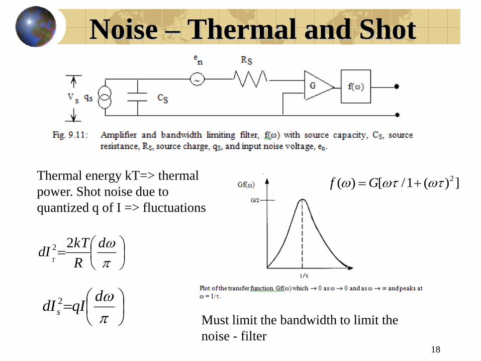
2( ) [ /1 ( ) ]f G
Must limit the bandwidth to limit the
noise - filter
Thermal energy kT=> thermal
power. Shot noise due to
quantized q of I => fluctuations

Base Resistance Noise V
19
/ 1/ ,B E mR kT qI g
)(09.0
2
,)(4.0
R
HznA
R
kT
HzAInAqI
d
g
kT
C
qI
CR
kT
RIdZIdZIdVd
mS
B
SS
BTCSSCST
2
)(
222
2222222
2 2 2
2 2
( ) ( / )
/2 4 2
BS
S m
V f dV d d
qIkT kTG C
R g
Base current of front end
transistor thermal noise
rms voltage due to
thermal source resistance,
base current shot noise
and thermal base
resistance.
Output voltage after the
bandwidth limiting filter.
Numerical values for shot
and thermal noise
ENC – Series and Parallel
20
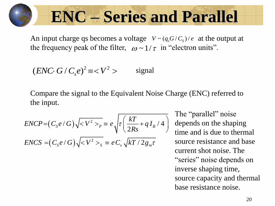
2 2( / )sENC G C e V
2
2
/ / 42
/ / 2
S P B
S S s m
kTENCP C e G V e q I
Rs
ENCS C e G V eC kT g
An input charge qs becomes a voltage at the output at
the frequency peak of the filter, in “electron units”.
Compare the signal to the Equivalent Noise Charge (ENC) referred to
the input.
~ ( / ) /s SV q G C e
~1/
The “parallel” noise
depends on the shaping
time and is due to thermal
source resistance and base
current shot noise. The
“series” noise depends on
inverse shaping time,
source capacity and thermal
base resistance noise.
signal
ENC – Parallel, Series and Shaping
21
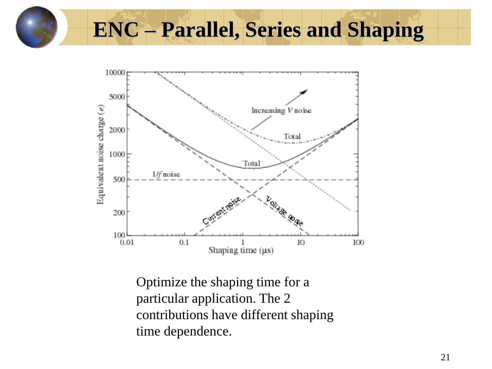
Optimize the shaping time for a
particular application. The 2
contributions have different shaping
time dependence.

ENC vs Input Capacity
22
Best Operation
•Low T
•Large Rs (current source)
•Small base current
•Small source capacity
•Small base resistance
•Short shaping time (HEP)
•Good front end transistor
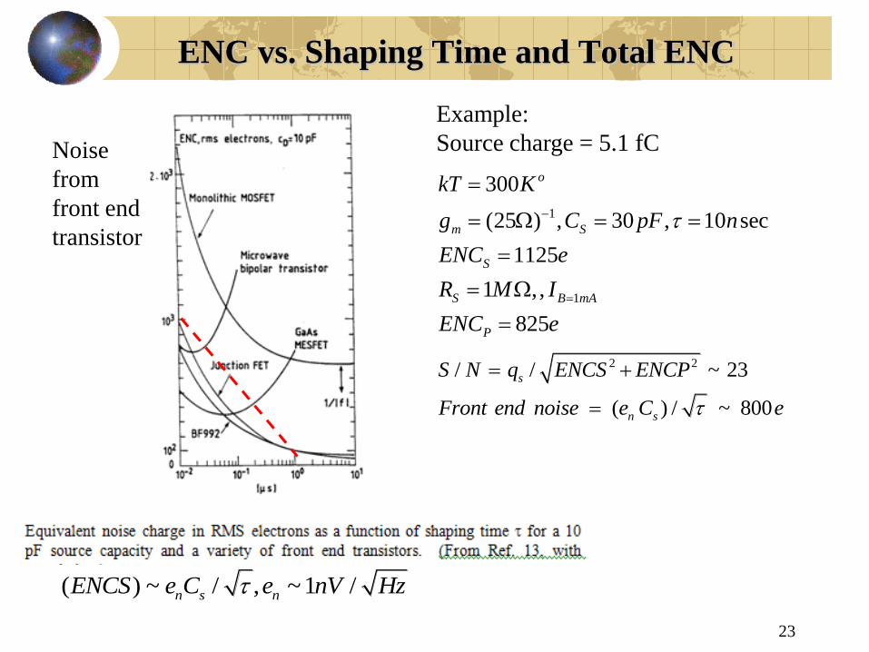
ENC vs. Shaping Time and Total ENC
23
2 2/ / ~ 23
( ) / ~ 800
s
n s
S N q ENCS ENCP
Front end noise e C e
( ) ~ / , ~1 /n s nENCS e C e nV Hz
Example:
Source charge = 5.1 fC
1
1
300
(25 ) , 30 , 10 sec
1125
1 ,,
825
o
m S
S
S B mA
P
kT K
g C pF n
ENC e
R M I
ENC e
Noise
from
front end
transistor
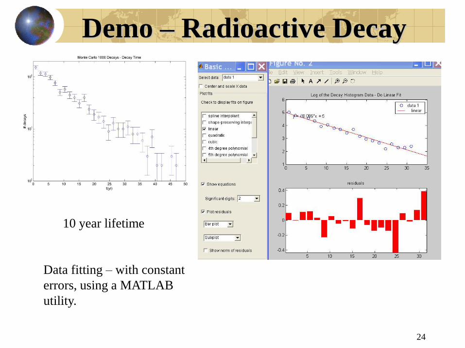
Demo – Radioactive Decay
24
10 year lifetime
Data fitting – with constant
errors, using a MATLAB
utility.

NR Dipole Radiation
25
2 2
22 2
2 2
2
3
2 3
sin~
~ ~ sin / ,
~
sin1/
4
2/
3
q arE
r c
u E qa rc energy density
P cr E
qad P d
c
P qa c
Translate electrostatic
results to NR radiative
solutions using the
addition of a factor =
dimensionless quantity –
acceleration causes
radiation.
Power through a
sphere is
independent of r =>
radiative solution.
Power is ~ square of
acceleration.
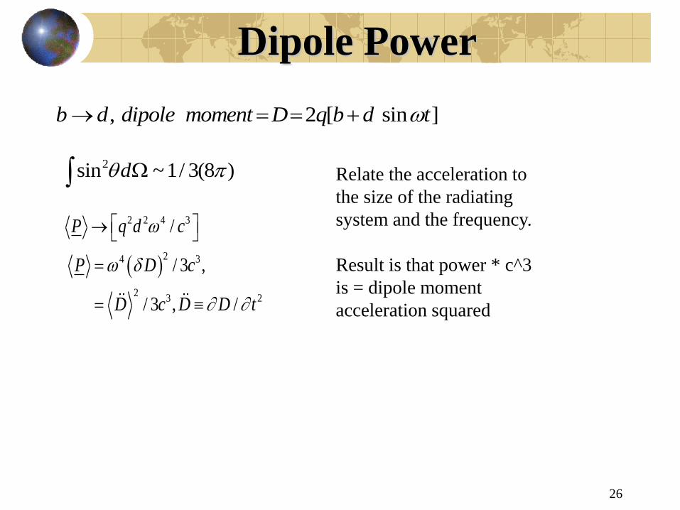
Dipole Power
26
, 2 [ sin ]b d dipole moment D q b d t
2sin ~1/ 3(8 )d
2 2 4 3
24 3
23 2
/
/ 3 ,
/ 3 , /
P q d c
P D c
D c D D t
Relate the acceleration to
the size of the radiating
system and the frequency.
Result is that power * c^3
is = dipole moment
acceleration squared

Thompson Scattering
27
2
, ( )4
8o
cS E B CGS
cS E
22 2
3sin
4
/o
d P ea
d c
a eE m
22 2 2
2
/ sin / /
8
3
T
T
de mc d P d S
d
2 4
0
2 4 8
0
8
3
/ ( )
/ ~ ~ 10
T
o
T
a
a Section I
a
Poynting vector
Dipole radiation
Scattering viewed as
the radiation of
incoming power
Cross section is Compton
wavelength squared times
fine structure constant
squared. Much smaller the
atomic cross section
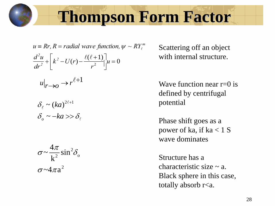
Thompson Form Factor
28
01)(
)(2
ur
rUkdr
ud
RY~ function, waveradialR Rr,u
2
2
2
m
1u rr o
2
o 2
2
4~ sin
k
~4 a
Scattering off an object
with internal structure.
Wave function near r=0 is
defined by centrifugal
potential
Phase shift goes as a
power of ka, if ka < 1 S
wave dominates
Structure has a
characteristic size ~ a.
Black sphere in this case,
totally absorb r<a.
2 1~ ( )
~o
ka
ka

Form Factor - II
29
Why is the sky blue ?
Scattering of the blue while
transmitting the yellow
wavelengths. Rayleigh
scattering.
Wave number
For square
well
Phase shift, S
wave
Small Uo
approximation.
“Form factor:
due to
structure of
scattering
objects.

Compton Scattering
30
UR scattering of e - e
SR Thompson/Compton
Scattering
In Thompson scattering the
radiation emitted has the
same frequency as the
incident wavelength.
However, as the photon
wavelength -> the e
Compton wavelength, the
emitted photons have a
lower energy as the recoil e
take off substantial energy.
The cross section then fall
with energy, in a fashion
clear from the Feynman
diagram.
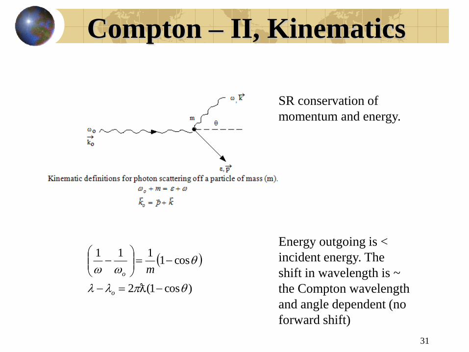
Compton – II, Kinematics
31
)cos1(2
cos1111
o
o m
SR conservation of
momentum and energy.
Energy outgoing is <
incident energy. The
shift in wavelength is ~
the Compton wavelength
and angle dependent (no
forward shift)
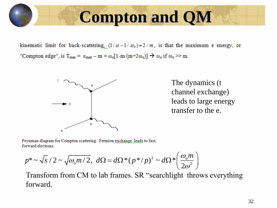
Compton and QM
32
2
2* ~ / 2 ~ / 2, *( * / ) ~ *
2
oo
mp s m d d p p d
The dynamics (t
channel exchange)
leads to large energy
transfer to the e.
Transform from CM to lab frames. SR “searchlight throws everything
forward.
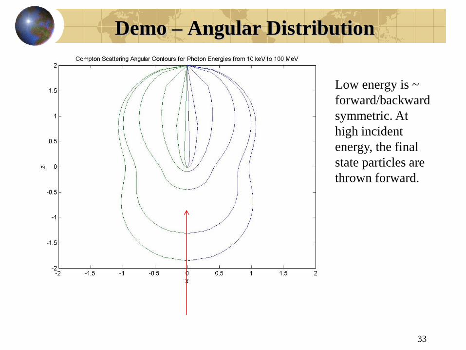
Demo – Angular Distribution
33
Low energy is ~
forward/backward
symmetric. At
high incident
energy, the final
state particles are
thrown forward.

Special Relativity
34
( , )x x ct
cv
csddxU
,
)/(/
2 2 2 2
2
( ) ( / )
1/ 1 , /
ds dx dx dx cdt cdt
v c
2
( , / )
( , ), /
/
p mU p c
m v c v dx dt
mc
p mc c
Formulated as 4
dimensional tensorial
objects – position,
velocity, momentum.
Instead of classical
mechanics and time as a
label, now need a
relativistic invariant –
proper time ds.
Momentum and energy
are conserved – not
kinematic energy due to
the rest energy.

35
Demonstration – Time Dilation
Tick/Tock – in
rest frame time
is measured on
a single clock
– proper time.
In the moving
frame the time
is measured on
spatially
separated,
synchronized,
clocks.
Basically, the
length the light
travels is just
longer.
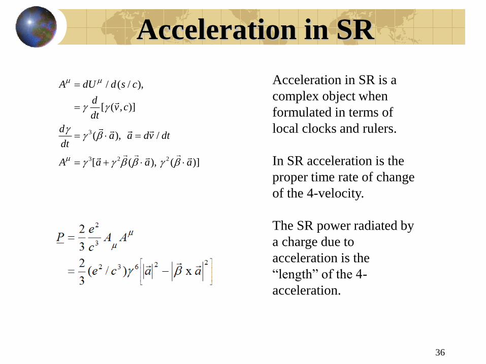
Acceleration in SR
36
3
3 2 2
/ ( / ),
[ ( , )]
( ), /
[ ( ), ( )]
A dU d s c
dv c
dt
da a dv dt
dt
A a a a
Acceleration in SR is a
complex object when
formulated in terms of
local clocks and rulers.
In SR acceleration is the
proper time rate of change
of the 4-velocity.
The SR power radiated by
a charge due to
acceleration is the
“length” of the 4-
acceleration.
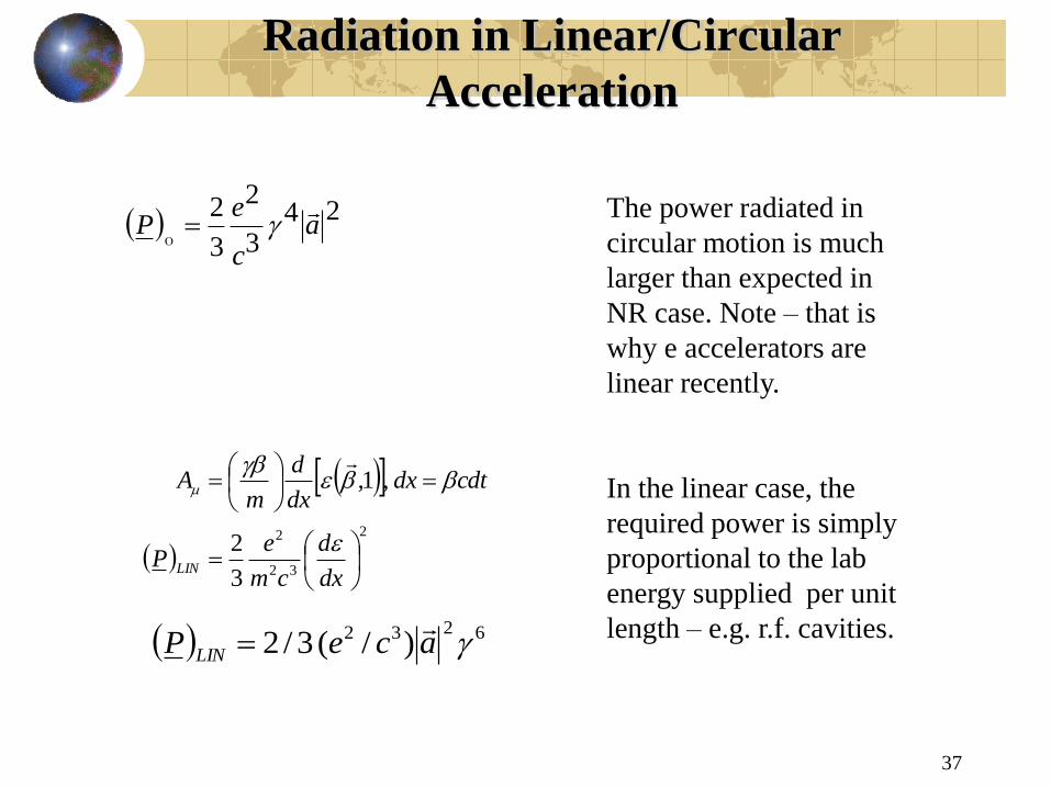
Radiation in Linear/Circular
Acceleration
37
243
2
3
2a
c
eP
2
32
2
3
2
,1,
dx
d
cm
eP
cdtdxdx
d
mA
LIN
6232 )/( 3/2 aceP LIN
The power radiated in
circular motion is much
larger than expected in
NR case. Note – that is
why e accelerators are
linear recently.
In the linear case, the
required power is simply
proportional to the lab
energy supplied per unit
length – e.g. r.f. cavities.

Searchlight Effect
38
)( * *cos *) *(1 cos *p
2
2
2
2
11
1
1 2
12
2(1 )
2
2
2
1 cos ~ 1 (1 / 2)
1 1~
2
~ 1/
Transform the energy of the
radiation from the C.M>
(starred) frame to the lab
observer frame.
For a more isotropic
distribution in the C.M, the
radiation in the lab frame is
typically localized in a
small angle region. This is
called the searchlight effect.

Demo - Radiation
39
linear circular
2 3 2 5
2 3 2
/ / 4 sin / (1 cos )
/ / 4 (sin )
LIN
LIN
d P d a c
d P d a c
NR dipole radiation
goes forward in
both the linear and
circular case.

Demo – “Searchlight”
40
The sharp rise
of the total
radiated power
with energy is
very evident,
as is the
forward nature
of the angular
distribution.
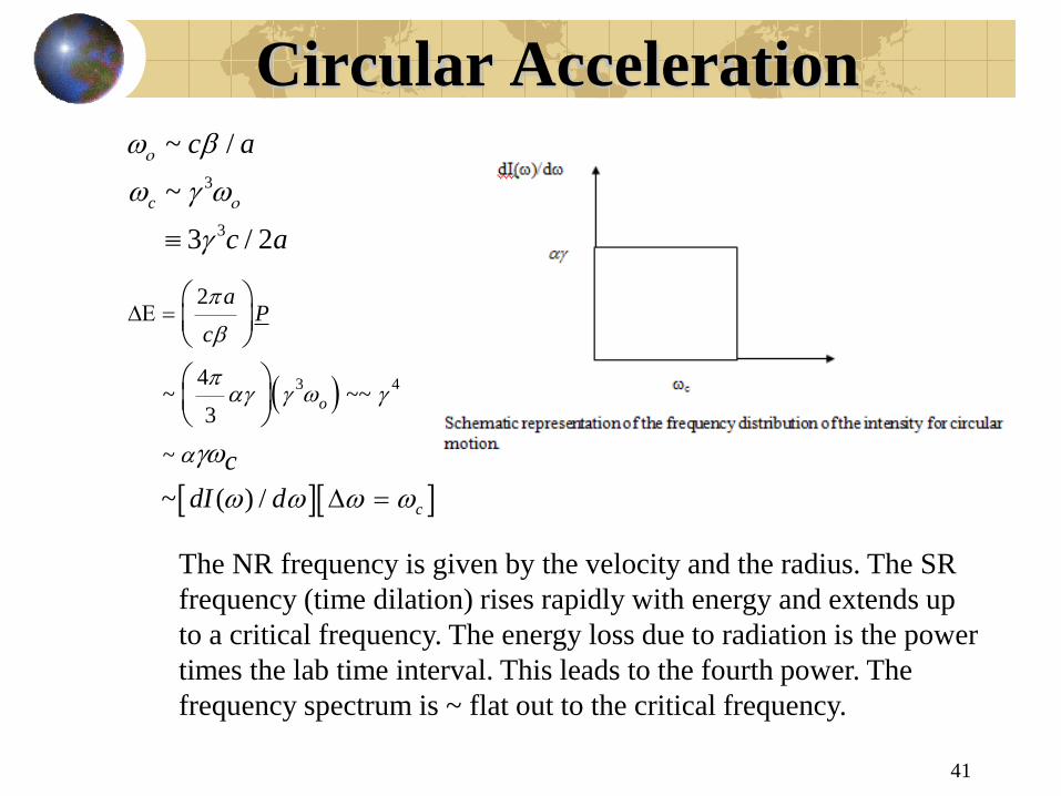
Circular Acceleration
41
3
3
~ /
~
3 / 2
c
c a
c a
3 4
2
4~ ~~
3
~
~ ( ) /
o
c
aP
c
c
dI d
The NR frequency is given by the velocity and the radius. The SR
frequency (time dilation) rises rapidly with energy and extends up
to a critical frequency. The energy loss due to radiation is the power
times the lab time interval. This leads to the fourth power. The
frequency spectrum is ~ flat out to the critical frequency.

Synchrotron Radiation
42
An e in a magnetic
field spirals around
the field line while
emitted synchrotron
radiation => smaller
radius of curvature –
the “death spiral”.
Numerical values for
e at bend radius a.
4
3
c
( ) 90[ ( )] / ( )
( ) 2.2 / ( )
E keV E GeV a m
keV E GeV a m

Demo – Circular, SR
43
As before,
the dipole
like pattern
become
much larger
in absolute
power
radiated and
become
much more
forward
peaked.
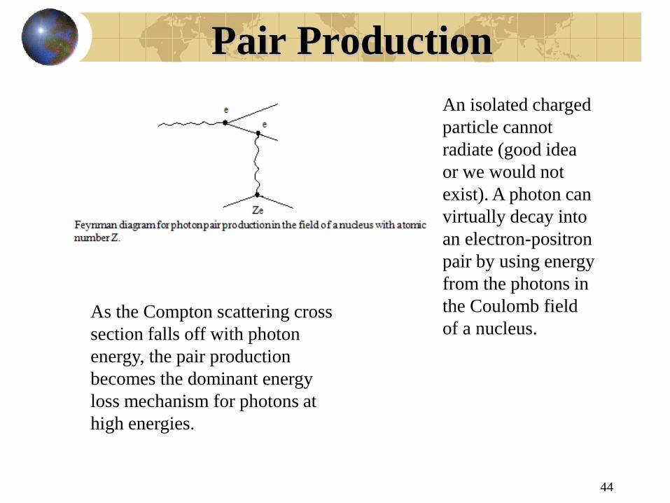
Pair Production
44
An isolated charged
particle cannot
radiate (good idea
or we would not
exist). A photon can
virtually decay into
an electron-positron
pair by using energy
from the photons in
the Coulomb field
of a nucleus. As the Compton scattering cross
section falls off with photon
energy, the pair production
becomes the dominant energy
loss mechanism for photons at
high energies.

Pair Production - II
45
7`
9pair B
22~ ln( )eB Z
3/ / (1/ )~
/ (1/ )
/
pair
B
d dy y
d dy y
y E E
Pair production and Bremmstrahlung are closely related processes
(later). They are coherent over the small size of the nucleus and go
like the third power of the fine structure constant – see Feynman
diagram. Pair production favors soft electrons.
Note the “death
spiral’

Bremm – WW Virtual Quanta
46
2
2
/
dU du E d bdb
dU d d
2/ 4 / lndU d
dU dN
2
2
( ) 1~ [ln( )]
2 1 1[ln( )]
dN
d
The nucleus can be viewed
as a source of virtual photons
which then scatter incoming
charged particles. Recall that
a Coulomb collision has
energy loss ~ the inverse of
the velocity squared.
The energy can be converted
from energy and frequency to
the number of virtual photons
of a given frequency. The
basic dependence of the
spectrum is that it falls as the
inverse of the photon energy.
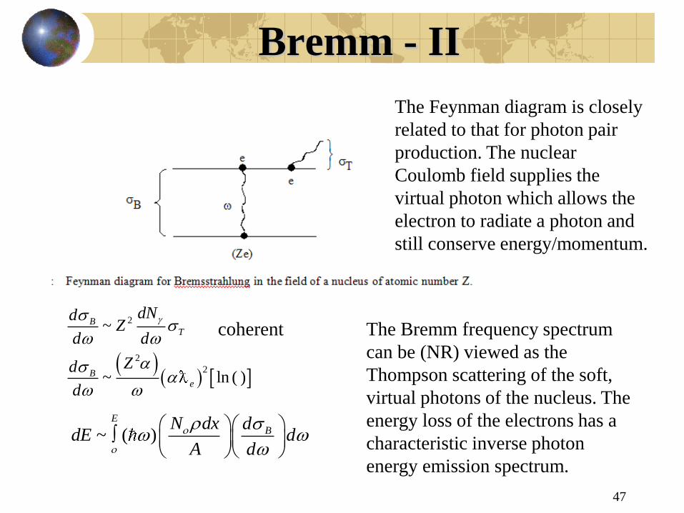
Bremm - II
47
2
2
2
~
~ ln ( )
BT
Be
dNdZ
d d
Zd
d
~ ( )E
BN dx d
dE dA d
The Feynman diagram is closely
related to that for photon pair
production. The nuclear
Coulomb field supplies the
virtual photon which allows the
electron to radiate a photon and
still conserve energy/momentum.
The Bremm frequency spectrum
can be (NR) viewed as the
Thompson scattering of the soft,
virtual photons of the nucleus. The
energy loss of the electrons has a
characteristic inverse photon
energy emission spectrum.
coherent
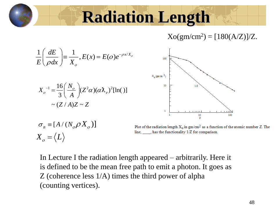
Radiation Length
48
/1 1, ( ) ( )
x XdEE x E e
E dx X
1 2 216( )( ) [ln( )]
3
~ ( / ) ~
e
NX Z
A
Z A Z Z
[ / ( )]B
A N X
X L
Xo(gm/cm2) = [180(A/Z)]/Z.
In Lecture I the radiation length appeared – arbitrarily. Here it
is defined to be the mean free path to emit a photon. It goes as
Z (coherence less 1/A) times the third power of alpha
(counting vertices).

Muon Energy Loss
49
Muons are just heavy electrons (so far), responding to the same forces
as electrons. That means the muon energy loss is dominated by
radiative processes at high energies.
2/ ~ ( / )c ce eE E m m
If the critical energy
was ~ 10 MeV for e,
then the critical
energy for muons will
be ~ 420 GeV. That
becomes important at
new colliders such as
the LHC

Tracker Material
For a complete understanding of the momentum scale and
resolution a detailed understanding of the tracker material
throughout the system is needed – use photon conversions
for high Z and nuclear interactions for low Z material.
radius
beam pipe, pixels, strips
50
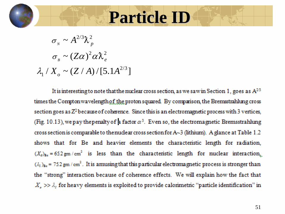
Particle ID
51
2/3 2
2 2
2/3
1
~
~ ( )
/ ~ ( / ) / [5.1 ]
N
B
p
e
o
A
Z
X Z A A