Embed Size (px)
Citation preview

Fundamentals of Angled-beam Ultrasonic NDE for Potential Characterization of Hidden Regions of
Impact Damage in Composites
John C. Aldrin2, a), John N. Wertz1, John T. Welter1, Sarah Wallentine1, Eric A. Lindgren1, Victoria Kramb3, David Zainey3
1Air Force Research Laboratory (AFRL/RXCA), Wright-Patterson AFB, OH 45433, USA 2Computational Tools, 4275 Chatham Avenue, Gurnee, IL 60031, USA
3 University of Dayton Research Institute, 300 College Park, Dayton OH 45469, USA
a) Corresponding author: [email protected]
Abstract. In this study, the use of angled-beam ultrasonic NDE was explored for the potential characterization of the hidden regions of impact damage in composites. Simulated studies using CIVA FIDEL 2D were used to explore this inspection problem. Quasi-shear (qS) modes can be generated over a wide range of angles and used to reflect off the backwall and interrogate under the top delaminations of impact damage. Secondary probe signals that do propagate normal to the surface were found to be significant under certain probe conditions, and can potentially interfere with weakly scattered signals from within the composite panel. Simulations were used to evaluate the source of the multiple paths of reflections from the edge of a delamination, whose time-of-flight and amplitude will depend on the depth of the delamination and location of neighboring delaminations. For angled-beam inspections, noise from both the top surface roughness and internal features was found to potentially mask the detection of signals from the edge of delaminations. Lastly, the potential of generating ‘guided’ waves along the backwall using an angled-beam source and subsequently measuring scattered signals from a far surface crack hidden under a delamination was explored.
INTRODUCTION
The increasing use of polymer-matrix composites (PMCs) for aircraft structures has led to an interest in improved lifecycle management through damage tolerance [1]. Following current practice for Aircraft Structural Integrity Program (ASIP) guidelines for metallic structures [2], the goal is to develop and validate damage progression models for composite structures. However, composite damage progression models are sensitive to the geometric complexity of typical damage modes [3]. Impact damage can exhibit a complex combination of plastic deformation, delaminations, matrix cracking, and possibly fiber breakage. A diagram is shown in Figure 1(a) with the key characteristics of impact damage organized by type and location with respect to the top surface: (1) deformation of front-wall surface, (2) delamination(s), front ‘profile’ (delamination area, depth), (3) matrix cracking connecting top delaminations, (4) extent of hidden (3D) delamination profile with depth, (5) deformation of back-wall surface, and (6) backwall matrix crack.
For in-service NDE of aircraft structures, there is the need to improve NDE characterization of impact damage [4-5]. Normal longitudinal ultrasonic testing (UT) can detect the presence of delaminations and some matrix cracking through a single-sided inspection; however, this technique does not address the hidden damaged region under the top delamination front. Examples of hidden impact damage are presented in Figures 1(b) and 1(c), showing the ‘hidden’ delamination ‘rosette’ profile and back-surface deformation profile respectively (measured using normal UT from the back-side surface). To detect and characterize such hidden damage from an external surface, an angled-beam method is proposed using quasi-shear waves, both direct and reflected paths, as shown in Figure 1(a). This approach builds upon prior work investigating polar backscatter ultrasonic techniques for composites [6-9]. Although, no work has

been found on polar backscatter for hidden impact damage characterization. The objective of this paper is to present the fundamentals of angled-beam ultrasonic techniques in composites to potentially characterize discontinuities in the ‘hidden’ region of impact damage, and consider some of the outstanding challenges for implementation.
FIGURE 1. (a) Diagram of normal and angled-beam ultrasonic testing (UT) of impact damage site. (b) Time-of-flight C-scan (in depth, mm) of the far side ‘hidden’ delamination profile, and (c) C-scan map (in mm) of the far surface deformation.
MODEL
To understand the complex propagation and scattering of ultrasonic waves in multilayer composites, a comprehensive NDE model is needed. In prior work [5], CIVA UT was used to study the simulated response from delaminations in a composite layer model using the homogenization method [10]. While simulations using a semi-analytical model with homogenized laminates are fast compared to numerical methods, the accuracy of the results are quite dependent on the validity of the homogenization process for the test specimen and inspection modality. For oblique inspection in composites, some of these model assumptions were found to break down.
A promising option in CIVA 2016, called CIVA FIDEL 2D, can address this need for improved accuracy while maintaining reasonable simulation time in modeling the incident field and scattering from defects in composite inspections. CIVA FIDEL incorporates a hybrid approach using semi-analytical models for ultrasonic transmit and receiver transducers in conjunction with a 2D finite difference time domain (FDTD) solution for modeling the local interaction and scattering from multilayer composites with discontinuities [11-12]. A screen shot of the CIVA FIDEL software interface is presented in Fig. 2. The composite layers can be modeled with a wide range of flexibility on layer orientation, including thin layer of epoxy between the ‘fiber with matrix’ sheets. Currently, four defect types can be modeled in CIVA FIDEL: square defects, delaminations, holes and layer waviness. The user can define the size of the numerical problem by constraining the mesh domain and implemented perfectly matched layer (PML) boundary conditions. Options for the numerical model are provided to set the mesh resolution relative to the wavelength of the probe center frequency. 2D simulations are much faster compared with full 3D representations, and they generally can provide satisfactory models to understand the key trends with varying inspection parameters, presence of multiple defects with varying location, presence of plastic deformation or cracking at the backwall surface. As well, CIVA FIDEL provides some very useful features for reviewing the simulated results; it is feasible to view the peak response in the specimen domain, and step through the transient response using 2D image views. More information on the formulation and applications of CIVA FIDEL can be found in references [11-12].
For this paper, a 24 ply composite laminate with a [-45/90/45/0]3s layup was simulated using nominal properties for IM7 carbon fiber and 977-3 epoxy matrix, with a fiber volume fraction of 0.6. Ultrasonic inspection parameters for much of the study used a 5 MHz, 6.35 mm diameter immersion transducer with 19 mm focal length, 17 mm water path, and water for the back wall coupling medium. Initial simulation time for one probe position at 5 MHz with a defect was on the order of 3 - 8 minutes, depending on the PC speed and number of cores available. This is considered quite reasonable, especially compared to full 3D numerical (FEM) simulations. Thus, simulating a B-scan of an impact damage region was quite feasible in 1-3 hours at 5 MHz and considerably faster at lower frequencies.
(a) (b) (c)
Normal UT Angled-beam UT
Impact damage site
θ
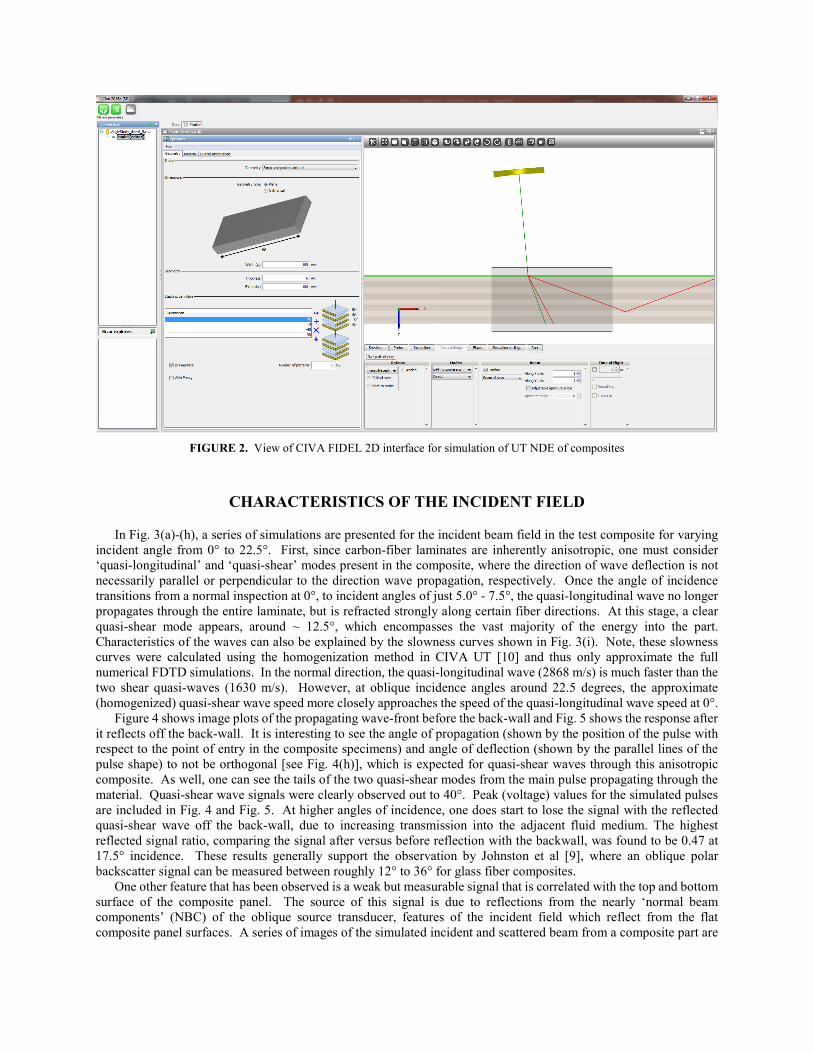
FIGURE 2. View of CIVA FIDEL 2D interface for simulation of UT NDE of composites
CHARACTERISTICS OF THE INCIDENT FIELD
In Fig. 3(a)-(h), a series of simulations are presented for the incident beam field in the test composite for varying incident angle from 0° to 22.5°. First, since carbon-fiber laminates are inherently anisotropic, one must consider ‘quasi-longitudinal’ and ‘quasi-shear’ modes present in the composite, where the direction of wave deflection is not necessarily parallel or perpendicular to the direction wave propagation, respectively. Once the angle of incidence transitions from a normal inspection at 0°, to incident angles of just 5.0° - 7.5°, the quasi-longitudinal wave no longer propagates through the entire laminate, but is refracted strongly along certain fiber directions. At this stage, a clear quasi-shear mode appears, around ~ 12.5°, which encompasses the vast majority of the energy into the part. Characteristics of the waves can also be explained by the slowness curves shown in Fig. 3(i). Note, these slowness curves were calculated using the homogenization method in CIVA UT [10] and thus only approximate the full numerical FDTD simulations. In the normal direction, the quasi-longitudinal wave (2868 m/s) is much faster than the two shear quasi-waves (1630 m/s). However, at oblique incidence angles around 22.5 degrees, the approximate (homogenized) quasi-shear wave speed more closely approaches the speed of the quasi-longitudinal wave speed at 0°.
Figure 4 shows image plots of the propagating wave-front before the back-wall and Fig. 5 shows the response after it reflects off the back-wall. It is interesting to see the angle of propagation (shown by the position of the pulse with respect to the point of entry in the composite specimens) and angle of deflection (shown by the parallel lines of the pulse shape) to not be orthogonal [see Fig. 4(h)], which is expected for quasi-shear waves through this anisotropic composite. As well, one can see the tails of the two quasi-shear modes from the main pulse propagating through the material. Quasi-shear wave signals were clearly observed out to 40°. Peak (voltage) values for the simulated pulses are included in Fig. 4 and Fig. 5. At higher angles of incidence, one does start to lose the signal with the reflected quasi-shear wave off the back-wall, due to increasing transmission into the adjacent fluid medium. The highest reflected signal ratio, comparing the signal after versus before reflection with the backwall, was found to be 0.47 at 17.5° incidence. These results generally support the observation by Johnston et al [9], where an oblique polar backscatter signal can be measured between roughly 12° to 36° for glass fiber composites.
One other feature that has been observed is a weak but measurable signal that is correlated with the top and bottom surface of the composite panel. The source of this signal is due to reflections from the nearly ‘normal beam components’ (NBC) of the oblique source transducer, features of the incident field which reflect from the flat composite panel surfaces. A series of images of the simulated incident and scattered beam from a composite part are

shown in Fig. 6. These signals originate from the tails of the focused beam, as shown in Fig. 6(a), associated with a diffraction effect at the edges (boundaries) of the transducer piezoelectric element, producing two cylindrical wave-fronts (from the perspective of this 2D view). The reflected signals from the top surface often return in pairs, as shown in Fig. 6(b) and 6(c). Normally, such signals are quite small relative to signals scattered by the focused portion of the beam. However, when attempting to generate a focused quasi-shear mode in a composite part and detect the primary and secondary diffraction signals from delamination edges, these reflected beam signals from the top surface can sometimes be of similar magnitude and time-of-flight as the discontinuity signals. Some studies have been performed, and it was discovered that by increasing the incidence angle, the magnitude of these reflected ‘normal beam component’ (RNBC) signals can be reduced.
FIGURE 3: Peak beam field in the simulated composite with varying incidence angle, θ: (a) 0°, (b) 2.5°, (c) 5°, (d) 7.5°, (e) 10°, (f) 12.5°, (g) 17.5°, (h) 22.5°. (i) Slowness curves of quasi-longitudinal and quasi-shear modes for the homogenized composite.
0°, Vpp = 171.1 (a) 5°, Vpp = 27.6 (b) 10°, Vpp = 172.2 (c) 12.5°, Vpp = 190.1 (d) 17.5°, Vpp = 233.4 (e) 22.5°, Vpp = 236.2 (f) 30°, Vpp = 258.1 (g) 40°, Vpp = 285.6 (h)
FIGURE 4. Transient beam field (at t= 18.75 us) in a composite with varying incidence angle, θ, from 0 to 40 degrees, presenting the transition from a quasi-longitudinal wave to a quasi-shear wave.
(a) (e)
(b) (f)
(c) (g)
(d) (h) (i)
Water Composite
Water Composite

0°, Vpp = 73.0 (a) 5°, Vpp = 27.6 (b) 10°, Vpp = 67.3 (c) 12.5°, Vpp = 85.2 (d) 17.5°, Vpp = 110.8 (e) 22.5°, Vpp = 106.5 (f) 30°, Vpp = 67.3 (g) 40°, Vpp = 59.4 (h)
FIGURE 5. Transient beam field (at t= 20.31 us) in a composite with varying incidence angle, θ, from 0 to 40 degrees, presenting the reflected quasi-longitudinal and quasi-shear waves from the backwall.
(a) (b) (c)
FIGURE 6. (a) Oblique beam in water incident on the composite panel. ‘Normal’ beam ‘tails’ with respect to the surface reflect back from the (b) top and (c) bottom surfaces, returning to pulse-echo transducer.
SCATTERING FROM A DELAMINATION EDGE
Simulated studies were also performed to better understand the scattering response from a delamination edge. A 5 MHz, 6.35 mm diameter immersion transducer with 19 mm focal length, 17 mm water path at 24 degrees oblique incidence was used for this study, shown in Figure 7(a). For this model, the delamination was located 1.0 mm down from the top surface. CIVA FIDEL was run with the probe centered on the delamination edge. The corresponding A-scan is presented in Figure 7(b). The primary signal is the direct tip diffracted signal (1), which has the shortest path for signals interacting with the delamination edge. Additional signals are observed in the A-scan and some care must be taken to identify the source and ray path. A diagram of the some of the key ray paths interacting with the delamination edge is shown in Figure 7(c). As well, a series of simulated 2D image plots are presented in Figure 8 for the focused beam quasi-shear wave incident at the delamination edge, and seven subsequent time steps, providing insight on the local scattered response. Prior to the direct edge diffraction signal in time, several smaller signals are observed in the A-scan. The source of these earlier signals is due to reflected normal beam component (RNBC) from the source transducer, discussed in the prior section. The reflected signals returning from the top surface do return in pairs, as shown in the A-scan in Fig. 7(b). In Fig. 8(a), one of these signals is shown reflecting from the top surface, just prior to the focused beam diffraction at the delamination.
With the probe beam centered on the delamination edge, several other multi-path signals can be observed after the primary direct diffraction signal. First, there is an interaction of the diffracted signal between the top surface and the delamination, signal (2), producing a signal approximately 0.75 µs after the diffracted signal. A shorthand notation for these signal paths can be used, defining the order of either the reflection off of composite panel boundary (b) and/or
Water Composite
Water Composite

12 14 16 18 20 22 24-0.25
-0.2
-0.15
-0.1
-0.05
0
0.05
0.1
0.15
0.2
0.25
time (µs)
sign
al (V
)
diffraction from the delamination edge (d). Thus, the shorthand for the first following signal is ‘d-b-d’. This path can be observed in Fig 8(b)-(8f). Next, there is another path for the diffracted signal (3) which first diffracts from the edge
FIGURE 7. (a) Diagram and (b) A-scan signal for a 5 MHz oblique (θ inc= 24°) UT inspection at a delamination edge. (c) Ray path of key delamination edge signals: (1) direct path (d = diffraction), (2) interaction with near surface (d-b-d; b= boundary), (3)
diffraction with far surface skip (d-b), (4) half skip with back-wall surface (b-d) (5) full skip with back-wall surface (b-d-b).
t = 8.75 µs (a) t = 9.06 µs (b)
t = 9.38 µs (c) t = 9.68 µs (d)
t = 10.00 µs (e) t = 10.31 µs (f)
t = 10.63 µs (g) t = 10.94 µs (h)
FIGURE 8. Series of simulated 2D results of incident quasi-shear wave scattering from a delamination edge for 8 time steps (a)-(h), highlighting (1) direct diffraction (d), (2) interaction with near surface (d-b-d) and (3) diffraction with far surface skip (d-b).
(c) (b)
(3)
(1)
(2) (RNBCs)
(a)
(3)
(4)
(5)
(1)
(2)
(3)

and then reflects from the bottom panel surface back to the transducer [path ‘d-b’, as shown in Figure 8(b)-(h)]. This second multipath signal is smaller in magnitude than the first, and is found in time approximately 1.5 µs after the primary diffracted signal. Lastly, other potential multiple signals are possible, but require the transducer to be positioned back from the transducer. These signals are defined as (4) the half skip signal with the back-wall surface (‘b-d’), and (5) the full skip with multiple reflections from the back-wall surface (‘b-d-b’), as shown in Fig 7(c). Of most interest, to interrogate the shadow region of the delamination, the full skip signal (5) provides the best opportunity to send ultrasonic signals under the front delaminations, and subsequently detect returning signals from hidden delamination and/or matrix cracks. However, the signal magnitudes are expected to be small, relative to the primary diffracted signal (1).
PROBLEM OF RESOLVING DELAMINATION SIGNALS FROM MATERIAL NOISE
Although simulation can provide significant insight into the oblique inspection of delaminations in composites, there are many practical challenges going forward when working with real impact specimens and performing experimental studies. First, optimization of NDE techniques using purely simulated studies will likely miss some key factors due to un-modeled characteristics of the inspection. For this problem, CIVA FIDEL provides an adequate representation of the scattered response from delaminations, and has been demonstrated to address contributions from normal beam component (NBC) panel signals. As well, CIVA FIDEL has shown the capability to simulate layer resonance ‘noise’ observed in normal ultrasonic inspection of composites [see ref. 11-12]. However, two features that are generally missing from ultrasonic simulations are noise signals due to surface roughness, and internal noise signals due to porosity and/or scattering from fiber bundles. Thus, going forward, a parallel set of experimental [13] and simulated [14] studies are underway to address optimization of the oblique UT technique for composite inspections.
Second, there is a need to verify the measurement model using a known standard discontinuity. For this effort, a side drilled hole (SDH) was proposed for use as a standard defect. Such reflectors are much larger than delamination edges and are expected to have better agreement with simulated results as well. One example is presented in Fig. 9 for a B-scan of a SDH using a 42° oblique 2.25 MHz focused 0.5" dia. (38.1 mm focal depth, 33 mm WP) transducer. For this study, the SDH was 0.96 mm in diameter and located 1.02 mm from the top surface. Through early work with experimental specimens, it was observed that operating at typical frequencies for normal ultrasonic scans of composites, 5 and 10 MHz, produced quite poor signal-to-noise for oblique UT inspection of composites. A designed experiment was performed to study the sensitivity of varying probe conditions and optimize the response from side drilled holes with respect to the various noise signals present in the part. For the experimental results shown in Fig. 9(b), significant surface and internal materials noise signals are observed, even when using a lower frequency 2.25 MHz transducer. More details on recent designed experimental studies for this inspection problem can be found in reference [13].
As well, for optimizing oblique inspections for the interrogation of hidden regions of impact damage, it is important to not only optimize the response for the direct signal for improved signal to noise, but also optimize the technique for sensitivity to the full skip signal off of the panel back-wall [see the diagram in Fig. 7(c)]. Thus, an important step is to validate the SDH response with simulation, not just for the primary, direct signal scattered from the hole, but also the secondary signals that interact with both the hole and the bottom and/or top surfaces. The full skip signal reflecting from the back-wall, following the direct signal in time, is of most interest. Thus, locating these secondary signals in the B-scans (in both time and space) after finding the primary signals is critical. Figure 9 presents an example of this comparison for an oblique (42 degree) 2.25 MHz focused probe. Note, poor signal-to-noise in the experimental results, and the general complexity of the signal interpretation problem has made quantitative comparisons difficult to date. More recent work on model benchmarking and full-skip signal identification can be found in references [14-15].
One challenge with this oblique UT inspection technique is resolving the multiple signals scattered from delamination edges at different depths. Because the scattered signals will interact with the composite panel surfaces, and neighboring delaminations (if present), manual interpretation of the paths for each signal can be quite complicated. To address this challenge, model-based inversion is proposed. Due to outstanding issues with low signal-to-noise in oblique UT experiments to date, a challenge problem was created using purely simulated data to explore the hidden delamination localization problem. A straightforward inversion problem was defined estimating the depth (in z) and lateral location (in x) of a second delamination with respect to a first delamination that is fixed at 1.0 mm in depth. A key feature of this inverse problem is developing a viable surrogate model for the ultrasonic simulated data tracking

multiple signals, using a limited set of simulation runs. For more information on progress on surrogate model representation and inversion problem demonstration for this problem space, see references [15-17].
(a) (b)
FIGURE 9. (a) CIVA Fidel 2D simulated results and (b) experimental B-scan results for an oblique (42 degree) 2.25 MHz focused 0.5" dia. (38.1 mm focal depth, 33 mm WP) UT scans from a side-drilled hole (SDH).
FEASIBILITY OF USING GUIDED WAVES TO INSPECT FOR FAR WALL CRACKS
The detect of far surface matrix cracks located in the backwall plastic deformation zone of impact damage are a unique challenge for external surface NDE techniques. This section explores the possibility of sending ultrasonic waves into composite panels, considering possible surface/guided waves that could propagate along the back-wall surface into the hidden region of the delamination, and interrogate this region for delaminations and/or matrix cracking. Figure 10 shows results for four simplified impact damage scenarios: (1) no delamination or crack, (2) with delamination only, (3) with crack only and (4) with delamination and crack in hidden region. In this study, a quasi-shear wave was generated using a 5 MHz, 40 degrees incidence beam in water. Figure 10 shows a single time step of the quasi-shear wave incident field interrogating the delamination region. The gain was increased in the plots to be able to highlight certain subtle features of the inspection. One characteristic is that there are two quasi-shear wave tails that ride along the top and bottom surfaces. While initially, there was some thought that these two waves are related to the two different quasi-shear modes in anisotropic materials (from slowness curve model), these signals were verified to be associate with the cylindrical wave tails of the probe beam (as shown in Figure 6). There are many interesting features to mention as the quasi shear wave interacts with the four different flaw scenarios. One can see the effect of the delamination in a number of ways, scattering the reflected signal from the far wall and generating diffractions as quasi-shear modes. Figure 11 shows a second snap-shot in time of the scattered field much later in time. Without the delamination above it, there is a strong diffracted (and corner reflection) crack signal that returns back toward the transducer, as shown in Fig. 11(c). However, some returning signals can also be found with the crack is hidden under the delamination, as shown in Fig. 11(d). However, this return signal is just more complex when it originates from a crack hidden under a delamination. As well, the returning signals are also smaller in magnitude. Special care will be required to detect such weak signals in practice. One other observation is that it is very difficult to resolve signal changes on the right side of the impact damage due to the presence of the small crack. This indicates the real challenge of attempting to use a multi-transducer pitch-catch approach for hidden damage characterization.
Lastly, one goal of this study was to explore the question of whether it is feasible to generate a quasi-Rayleigh (qR) wave on the back surface of the composite. This signal was observed, especially later in time after interaction with the crack, as shown in Figure 11(c). It appears to be slower than the qS modes, which is expected. As well, it does not appear that a significant qR wave is generated until after the waves interact with the crack. The one issue from the perspective of ultrasonic inspection is that the qR wave does not 'leak' back into the composite. This is reasonable (in hindsight) since Rayleigh waves on flat surfaces are not expected to leak energy into the material. One can potentially observe coupling between the far and near surfaces for surface waves, however, not at the higher frequency (5 MHz) for this simulated study. Although, due to poor generation and no observed leaking of the qR wave, this does not negate the viability of this inspection technique. There is still a significant generation of a 'quasi-
(1) (2)
(3) (4) (5)
probe position (mm)
time
( µs)
80 90 100 110 120 130
64
66
68
70
72
74
76
78
80
82
840
20
40
60
80
100
120SDH
(1)
surface noise polished region (internal noise)

shear wave' front that interacts with the bottom surface (as well as additional signals that reflect between the backwall and the delamination) and is observed to propagate back up to the top surface for detection. In summary, it is feasible to generate quasi-shear waves to inspection the hidden delamination region. Future work is planned to implement model-based inversion to address this rather complex data interpretation task
(a) (b)
(c) (d)
FIGURE 10. Image plot of incident field at time 22.03 µs, in a composite panel for four discontinuity scenarios: (a) no delamination or far crack, (b) delamination only, (c) far crack only and (d) delamination with hidden far crack.
(a) (b)
(c) (d)
FIGURE 11. Image plots of scattered field at time 22.81 µs, in a composite panel for four discontinuity scenarios: (a) no delamination or far crack, (b) delamination only, (c) far crack only and (d) delamination with hidden far crack.
CONCLUSIONS AND FUTURE WORK
In this study, the use of angled-beam ultrasonic NDE was explored for the potential characterization of the hidden regions of impact damage in composites. Simulated studies using CIVA FIDEL 2D were used to study this problem. Quasi-shear (qS) modes can be generated over a wide range of angles and used to reflect off the backwall and interrogate under the top delaminations of impact damage. Secondary probe signals that do propagate normal to the surface were found to be significant under certain probe conditions, and can potentially mask weakly scattered signals from within the composite panel. Simulations were used to evaluate the source of the multiple paths of reflections from the edges of a delamination, whose time-of-flight and amplitude will depend on the depth of the delamination and location of neighboring delaminations. For these angled-beam inspections, noise from both the top surface roughness and internal features were found to potentially mask the detection of signals from edges of delaminations.
Secondary diffracted qS waves
qR waves
numerical shadow region
Parallel work is on-going to address these challenges, through empirical and simulated oblique UT optimization studies [13-14], and through a challenge problem investigating model-based inversion for hidden delamination localization [15-17]. Lastly, the potential of generating ‘guided’ waves along the backwall using an angled-beam source and subsequently measuring scattered signals from a far surface crack hidden under a delamination was found to be feasible. However, more work is needed to validate the approach using experimental studies.
ACKNOWLEDGMENTS
Portions of this work were funded by the U.S. Air Force Research Laboratory, Materials and Manufacturing Directorate through contracts FA8650-15-D-5231 TO 001 (Computational Tools) and FA8650-14-D-5224 (UDRI).
REFERENCES
1. D. Mollenhauer, E. Iarve, K. Hoos, M. Flores, E. Lindgren and G. Schoeppner, "Damage tolerance for life management of composite structures - part 1: modeling," in The Aircraft Structural Integrity Program Conference, ASIP Conference Proceedings, (2016).
2. C. A. Babish IV, "USAF ASIP: protecting safety for 50 years," Proceedings of the 2008 Aircraft Structural Integrity Conference, (2008).
3. M. Flores, "Damage tolerance and assessment of unidirectional carbon fiber composites: an experimental and numerical study," Ph. D. Thesis, The University of Texas at El Paso, (2016).
4. E. A. Lindgren, "US Air Force perspective on validated NDE – Past, present, and future," Review of Progress in Quantitative Nondestructive Evaluation, AIP Conf. Proc., Vol. 1706, p. 020002. (2016).
5. J. Wertz, S. Wallentine, J. Welter, J. Dierken and J. Aldrin, "Volumetric characterization of delamination fields via angle longitudinal wave ultrasound," Review of Progress in Quantitative Nondestructive Evaluation, AIP Conf. Proc., Vol. 1806, p. 090006, (2017).
6. Y. Bar-Cohen and R. L. Crane, "Nondestructive evaluation of fiber-reinforced composites with acoustic backscattering measurements," Composite Materials: Testing and Design (Sixth Conference), American Society for Testing and Materials, ASTM STP 787 343-354, (1982).
7. Y. Bar-Cohen and R. L. Crane, "Acoustic-backscattering imaging of subcritical flaws in composites," Materials Evaluation, Vol. 40, pp. 970-975, (1982).
8. N. Balhi, N. Vrellos, B. W. Drinkwater, F. J. Guild, S. L. Ogin and P. A. Smith, "Intra-laminar cracking in CFRP laminates: observations and modelling," Journal of Materials Science, Vol. 41, pp. 6599-6609, (2006).
9. P. H. Johnston, C. D. Appleget and M. T. Odarczenko, "Characterization of delaminations and transverse matrix cracks in composite laminates using multiple-angle ultrasonic inspection," Review of Progress in Quantitative Nondestructive Evaluation, AIP Conf. Proc., Vol. 1511, 1011-1018, (2013).
10. S. Deydier, N. Leymarie, P. Calmon and V. Mengeling, “Modeling of the Ultrasonic Propagation into Carbon-Fiber-Reinforced Epoxy Composites, Using a Ray Theory Based Homogenization Method,” Review of Progress in Quantitative Nondestructive Evaluation, 25, AIP Conf. Proc., Vol. 820, pp. 972-978, (2006).
11. N. Dominguez and F. Reverdy, "Simulation of Ultrasonic Testing of Composite Structures," 11th European Conference on Non-Destructive Testing / ECNDT 2014, (Prague, Czech Republic, October 6-10, 2014), web site: http://www.ndt.net/events/ECNDT2014/app/content/Paper/344_Dominguez.pdf.
12. K. Jezzine, D. Ségur, R. Ecault, N. Dominguez, P. Calmon, “Hybrid Ray-FDTD model of the simulation of the ultrasonic inspection of CFRP parts,” Review of Progress in Quantitative Nondestructive Evaluation, AIP Conf. Proc., Vol. 1806, p. 090016, (2017).
13. C. Henry, V. Kramb, J. Welter, J. Wertz, E. A. Lindgren, J. Aldrin, D. Zainey, "Optimization of an angle-beam ultrasonic approach for characterization of impact damage in composites," Review of Progress in Quantitative Nondestructive Evaluation, AIP Conf. Proc., (in this proceedings, expected 2018).
14. J. Welter, J. Wertz, J. C. Aldrin, V. Kramb, D. Zainey, "Model-driven optimization of oblique angle ultrasonic inspection parameters for delamination characterization," Review of Progress in Quantitative Nondestructive Evaluation, AIP Conf. Proc., (in this proceedings, expected 2018).
15. J. Wertz, L. Homa, D. Sparkman, J. Welter, J. C. Aldrin, "Model comparison by signal decomposition parameter evaluation," Review of Progress in Quantitative Nondestructive Evaluation, AIP Conf. Proc., (in this proceedings, expected 2018).
16. L. Homa, D. Sparkman, J. Wertz, J. Welter, J. C. Aldrin, " Signal decomposition for surrogate modeling of a constrained ultrasonic design space," Review of Progress in Quantitative Nondestructive Evaluation, AIP Conf. Proc., (in this proceedings, expected 2018).
17. D. Sparkman, J. Wertz, L. Homa, J. Welter, J. C. Aldrin, "Direct inverse modelling for ultrasound delamination characterization in composite," Review of Progress in Quantitative Nondestructive Evaluation, AIP Conf. Proc., (in this proceedings, expected 2018).


![Fatigue Flaw NDE Reference Standard Development - Phase … · ultrasonic testing (UT), ... (EMAT), phased array ultrasound, and long-range guided wave (LRGW)]; electromagnetic methods](https://img.dokumen.tips/doc/110x75/5ac244ba7f8b9ae45b8e57f7/fatigue-flaw-nde-reference-standard-development-phase-testing-ut-emat.jpg)


