Embed Size (px)
Citation preview
Fundamentals, Design, and Implementation, 9/e
COS 346
Day 8

Chapter 5/2 Copyright © 2004
Database Processing: Fundamentals, Design, and Implementation, 9/e by David M. Kroenke
Agenda
Capstone proposals due– Timing of deliverables is 10% of grade
Assignment # 4 Due Assignment #5 Posted Due Feb 19 First Exam Graded
– I B , 5 Cs and I no take Quiz two Feb 26
– Chap 4 & 5 in Kroenke Text and Chap 1 of Hotka Text – 20 M/C; 5 Short essays– 60 min WebCT, Open book
Today we look at Transforming a model into a Database Design
Next week we’ll take a look at Oracle 9i

Fundamentals, Design, and Implementation, 9/e
Chapter 5Database Design

Chapter 5/4 Copyright © 2004
Database Processing: Fundamentals, Design, and Implementation, 9/e by David M. Kroenke
The Database Design Process
Create tables and columns from entities and attributes
Select primary keys Represent relationships Specify constraints Re-examine normalization criteria

Chapter 5/5 Copyright © 2004
Database Processing: Fundamentals, Design, and Implementation, 9/e by David M. Kroenke
Elements of Database Design

Chapter 5/6 Copyright © 2004
Database Processing: Fundamentals, Design, and Implementation, 9/e by David M. Kroenke
Transforming an Entity to a Table
Chapter 5/7 Copyright © 2004
Database Processing: Fundamentals, Design, and Implementation, 9/e by David M. Kroenke
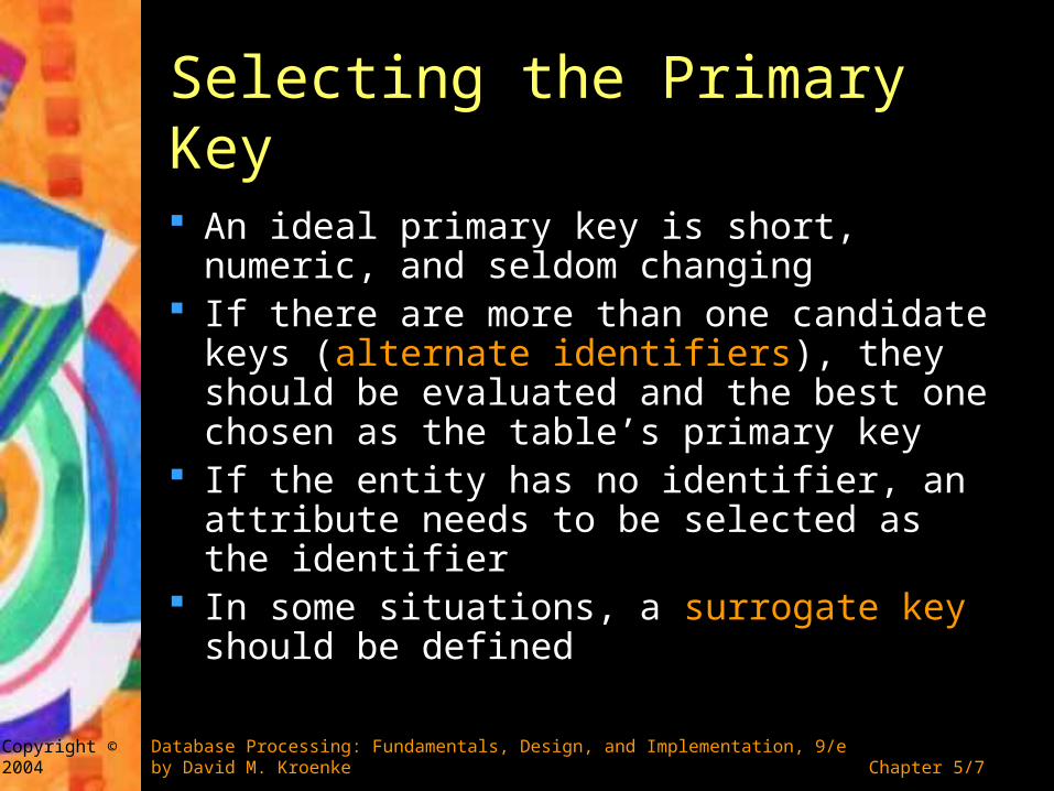
Selecting the Primary Key
An ideal primary key is short, numeric, and seldom changing
If there are more than one candidate keys (alternate identifiers), they should be evaluated and the best one chosen as the table’s primary key
If the entity has no identifier, an attribute needs to be selected as the identifier
In some situations, a surrogate key should be defined

Chapter 5/8 Copyright © 2004
Database Processing: Fundamentals, Design, and Implementation, 9/e by David M. Kroenke
Surrogate Keys
A surrogate key is a unique, DBMS-supplied identifier used as the primary key of a relation
The values of a surrogate key have no meaning to the users and are normally hidden on forms and reports
DBMS does not allow the value of a surrogate key to be changed
Disadvantages: – Foreign keys that are based on surrogate keys have no
meaning to the users– When data shared among different databases contain
the same ID, merging those tables might yield unexpected results

Chapter 5/9 Copyright © 2004
Database Processing: Fundamentals, Design, and Implementation, 9/e by David M. Kroenke
Example: Surrogate Keys

Chapter 5/10 Copyright © 2004
Database Processing: Fundamentals, Design, and Implementation, 9/e by David M. Kroenke
Representing Relationships
Relationships are expressed by placing the primary key of one table into a second table
The new column in the second table is referred to as a foreign key
Three principles of relationship representation– Preservation of referential integrity constraints– Specification of referential integrity actions– Representation of minimum cardinality

Chapter 5/11 Copyright © 2004
Database Processing: Fundamentals, Design, and Implementation, 9/e by David M. Kroenke
Rules for Referential Integrity Constraints
Chapter 5/12 Copyright © 2004
Database Processing: Fundamentals, Design, and Implementation, 9/e by David M. Kroenke
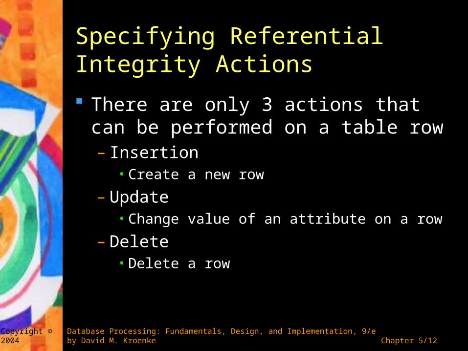
Specifying Referential Integrity Actions
There are only 3 actions that can be performed on a table row– Insertion
• Create a new row
– Update• Change value of an attribute on a row
– Delete• Delete a row

Chapter 5/13 Copyright © 2004
Database Processing: Fundamentals, Design, and Implementation, 9/e by David M. Kroenke
Specifying Referential Integrity Actions If default referential integrity constraint is too
strong, overriding the default referential integrity enforcement could be defined during database design
The policy will be programmed into triggers during implementation
Two referential integrity overrides– Cascading updates automatically change the value of the
foreign key in all related child rows to the new value– Cascading deletions automatically delete all related child
rows

Chapter 5/14 Copyright © 2004
Database Processing: Fundamentals, Design, and Implementation, 9/e by David M. Kroenke
Enforcing Minimum Cardinality
If the minimum cardinality on the child is one, at least one child row must be connected to the parent
A required parent can be specified by making the foreign key value not null
A required child can be represented by creating update and delete referential integrity actions on the child and insert referential integrity actions on the parent
Such referential integrity actions must be declared during database design and trigger codes must be written during implementation

Chapter 5/15 Copyright © 2004
Database Processing: Fundamentals, Design, and Implementation, 9/e by David M. Kroenke
Comparing Relationship terminology

Chapter 5/16 Copyright © 2004
Database Processing: Fundamentals, Design, and Implementation, 9/e by David M. Kroenke
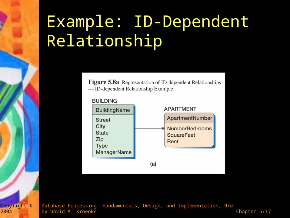
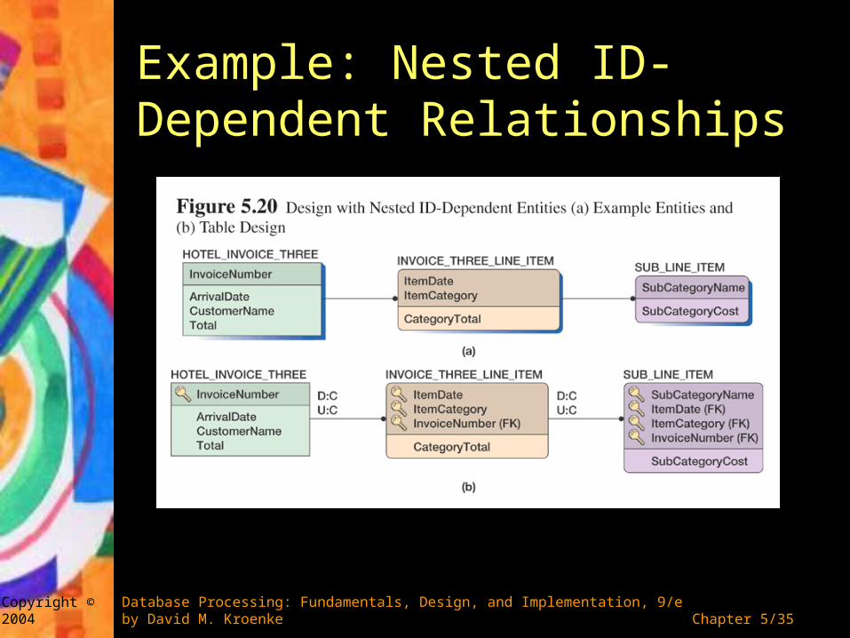
Representing ID-Dependent Relationships To represent ID-dependent relationships, primary
key of the parent relation is added to the child relation
The new foreign key attribute becomes part of the child’s composite primary key
Referential integrity actions should be carefully determined– For cascading updates, data values are updated to keep
child rows consistent with parent rows– If the entity represents multi-value attributes, cascading
deletions are appropriate– Check user requirements when designing more complex
situation
Chapter 5/17 Copyright © 2004
Database Processing: Fundamentals, Design, and Implementation, 9/e by David M. Kroenke
Example: ID-Dependent Relationship

Chapter 5/18 Copyright © 2004
Database Processing: Fundamentals, Design, and Implementation, 9/e by David M. Kroenke
Example: ID-Dependent Relationship

Chapter 5/19 Copyright © 2004
Database Processing: Fundamentals, Design, and Implementation, 9/e by David M. Kroenke
Example: Cascading Deletion

Chapter 5/20 Copyright © 2004
Database Processing: Fundamentals, Design, and Implementation, 9/e by David M. Kroenke
Representing Relationship Using Surrogate Keys If the parent in an ID-dependent relationship has a
surrogate key as its primary key, but the child has a data key, use the parent’s surrogate key as a primary key
A mixture of a surrogate key with a data key does not create the best design as the composite key will have no meaning to the users
Therefore, whenever any parent of an ID-dependent relationship has a surrogate key, the child should have a surrogate key as well
By using surrogate keys in the child table, the relationship type has changed to 1:N non-identifying relationship

Chapter 5/21 Copyright © 2004
Database Processing: Fundamentals, Design, and Implementation, 9/e by David M. Kroenke
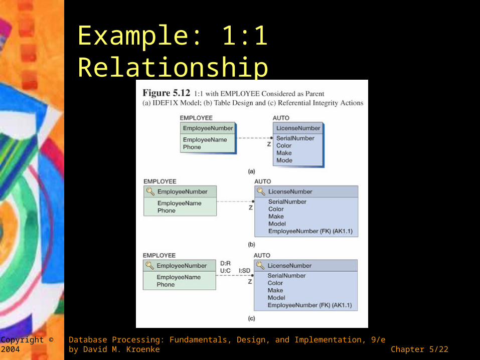
Representing 1:1 and 1:N Relationships IDEF1X refers to 1:1 and 1:N as
Non-identifying connection relationships General rule: the key of a parent table is
always placed into the child– For 1:1 relationship, either entity could be
considered the parent or the child– For 1:N relationship, the parent entity is always
the entity on the one side
Chapter 5/22 Copyright © 2004
Database Processing: Fundamentals, Design, and Implementation, 9/e by David M. Kroenke
Example: 1:1 Relationship

Chapter 5/23 Copyright © 2004
Database Processing: Fundamentals, Design, and Implementation, 9/e by David M. Kroenke
Example: 1:1 Relationship

Chapter 5/24 Copyright © 2004
Database Processing: Fundamentals, Design, and Implementation, 9/e by David M. Kroenke
Example: 1:N Relationship

Chapter 5/25 Copyright © 2004
Database Processing: Fundamentals, Design, and Implementation, 9/e by David M. Kroenke
Representing N:M Relationships
IDEF1X refers to N:M relationships as non-specific relationships
N:M relationships need to be converted into two ID-dependent relationships by defining an intersection table
Two referential integrity constraints will be created– The minimum cardinality from the child to the parent is
always one– The minimum cardinality from the parent to the
intersection table depends on the system requirements

Chapter 5/26 Copyright © 2004
Database Processing: Fundamentals, Design, and Implementation, 9/e by David M. Kroenke
Example: N:M Relationship
Chapter 5/27 Copyright © 2004
Database Processing: Fundamentals, Design, and Implementation, 9/e by David M. Kroenke
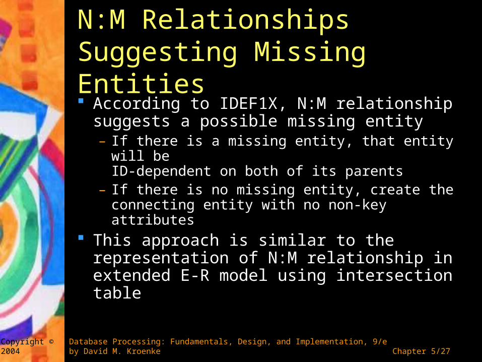
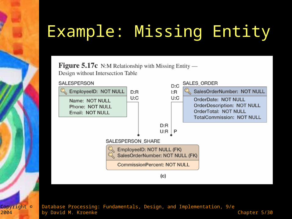
N:M Relationships Suggesting Missing Entities According to IDEF1X, N:M relationship
suggests a possible missing entity– If there is a missing entity, that entity will be
ID-dependent on both of its parents– If there is no missing entity, create the
connecting entity with no non-key attributes This approach is similar to the
representation of N:M relationship in extended E-R model using intersection table

Chapter 5/28 Copyright © 2004
Database Processing: Fundamentals, Design, and Implementation, 9/e by David M. Kroenke
Example: Missing Entity

Chapter 5/29 Copyright © 2004
Database Processing: Fundamentals, Design, and Implementation, 9/e by David M. Kroenke
Example: Missing Entity
Chapter 5/30 Copyright © 2004
Database Processing: Fundamentals, Design, and Implementation, 9/e by David M. Kroenke
Example: Missing Entity

Chapter 5/31 Copyright © 2004
Database Processing: Fundamentals, Design, and Implementation, 9/e by David M. Kroenke
Representing Subtype Relationships Called subtypes in the extended E-R model and
categories in the IDEF1X model Primary key of the supertype (or generic) entity is
placed into the subtype (or category entity) Category entities in IDEF1X are mutually exclusive
in the categories– For complete categories, the generic entity will have to
have exactly one category entity in that cluster– These constraints are enforced by properly specifying
referential integrity actions

Chapter 5/32 Copyright © 2004
Database Processing: Fundamentals, Design, and Implementation, 9/e by David M. Kroenke
Example: Subtype Relationship

Chapter 5/33 Copyright © 2004
Database Processing: Fundamentals, Design, and Implementation, 9/e by David M. Kroenke
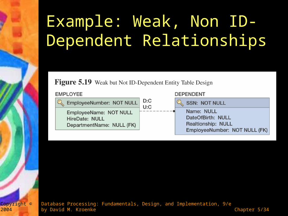
Representing Weak Entities
Weak entities logically depend on the existence of another entity in the database
Representing these entities are the same as modeling 1:1 or 1:N relationships
Referential integrity actions need to be specified to ensure that – When the parent is deleted, the weak entity is
deleted as well– New weak entities have a parent with which to
connect
Chapter 5/34 Copyright © 2004
Database Processing: Fundamentals, Design, and Implementation, 9/e by David M. Kroenke
Example: Weak, Non ID-Dependent Relationships
Chapter 5/35 Copyright © 2004
Database Processing: Fundamentals, Design, and Implementation, 9/e by David M. Kroenke
Example: Nested ID-Dependent Relationships

Chapter 5/36 Copyright © 2004
Database Processing: Fundamentals, Design, and Implementation, 9/e by David M. Kroenke
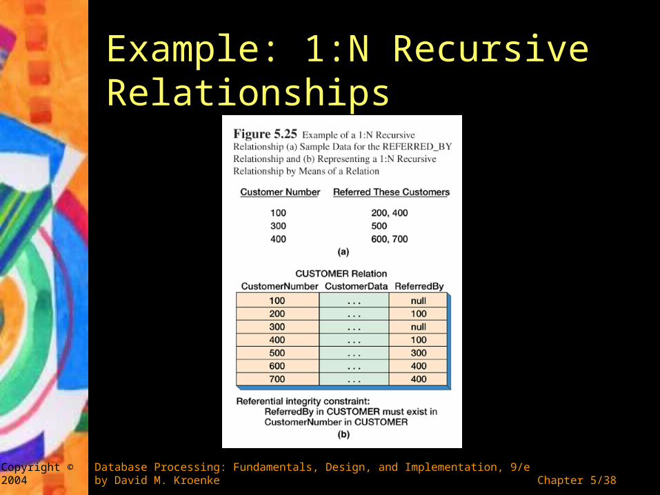
Representing Recursive Relationships A recursive relationship is a relationship
among entities of the same class For 1:1 and 1:N recursive relationships,
add a foreign key to the relation that represents the entity
For N:M recursive relationships, add a new intersection table that represents the N:M relationship

Chapter 5/37 Copyright © 2004
Database Processing: Fundamentals, Design, and Implementation, 9/e by David M. Kroenke
Example: 1:1 Recursive Relationships
Chapter 5/38 Copyright © 2004
Database Processing: Fundamentals, Design, and Implementation, 9/e by David M. Kroenke
Example: 1:N Recursive Relationships

Chapter 5/39 Copyright © 2004
Database Processing: Fundamentals, Design, and Implementation, 9/e by David M. Kroenke
Example: M:N Recursive Relationships

Chapter 5/40 Copyright © 2004
Database Processing: Fundamentals, Design, and Implementation, 9/e by David M. Kroenke
Representing Ternary and Higher-Order Relationships Ternary and higher-order relationships can be
treated as combinations of binary relationships There are three types of binary constraints:
MUST, MUST NOT, and MUST COVER– MUST NOT constraint: the binary relationship indicates
combinations that are not allowed to occur in the ternary relationship
– MUST COVER constraint: the binary relationship indicates all combinations that must appear in the ternary relationship
Because none of these constraints can be represented in the relational design, they must be documented as business rules and enforced in application programs or triggers
Chapter 5/41 Copyright © 2004
Database Processing: Fundamentals, Design, and Implementation, 9/e by David M. Kroenke
Null values
A null value is an attribute value that has not been supplied
Null values are ambiguous as they can mean– The value is unknown– The value is inappropriate– The value is known to be blank
Inappropriate nulls can be avoided by– Defining subtype or category entities– Forcing attribute values through the use of not null– Supplying initial values
Ignore nulls if the ambiguity is not a problem to the users

Fundamentals, Design, and Implementation, 9/e
Chapter 5Database Design