Embed Size (px)
Citation preview

Fundamental X-mode Electron Cyclotron Current Drive using Remote-Steering Symmetric Direction Antenna
at Larger Steering Angles
H. Idei1, K. Hanada1, H. Zushi1, K. Ohkubo2, M. Hasegawa1, S. Kubo2, K. N. Sato1, K. Nakamura1, M. Sakamoto1, A. Iyomasa1, S. Kawasaki1, H. Nakashima1, A.Higashijima1, T. Notake3, T .Shimozuma2, S. Ito2, H. Hoshika4, N. Maezono4, S. Nishi4, K. Nakashima4
and TRIAM Experimental. Group1
1 Research Institute for Applied Mechanics, Kyushu University, Kasuga, 816-8580, Japan 2 National Institute for Fusion Science, Toki, 509-5292, Japan
3 Faculty of Engineering, Nagoya University, Nagoya, 464-8603, Japan 4Interdisciplinary Graduate School of Engineering Sciences, Kyushu University, Kasuga,
816-8580, Japan
The 20th IAEA Conference, PD/1-2 H. Idei et al.

OutlineTRIAM, Advanced Fusion Research Center
1. Introduction Remote Steering Antenna relevant to ITER Application New Hardware on ECH/ECCD after the 19th IAEA in TRIAM-1M
2. Symmetric Direction Remote Steering Antenna with Larger Steering Angles Output Beam Pattern ---- Gaussian Content ---- Output Steering Angle [ based on Intensity & Phase Measurements ] Transmission Efficiency
3. ECH / ECCD Experiments on the TRIAM-1M tokamak Mode Purity Control Experiment O-mode Experiment X-mode Experiment
4. Summary
The 20th IAEA Conference, PD/1-2 H. Idei et al.

Remote Steering Antenna with Symmetric- and Asymmetric- Angles
Asymmetric
direction
θaa L Symmetric
direction
TRIAM, Advanced Fusion Research Center
f : 170GHza : 31.75mm
Transmission efficiency = P out / P in
: perpendicular field to steering planeE
(K.Ohkubo)
Dependence of Transmission Efficiency on θ and L
[imaging property in fundamental mode]
20
10
00.0 0.5 1.0 1.5 2.0 2.5 3.0
L[m]
θ [deg.]
20
10
00.0 0.5 1.0 1.5 2.0 2.5 3.0
L[m]
Extended Steering Capability
0.0
0.2
0.4
0.6
0.8
1.0
0 5 10 15 20Steering Angle [ degrees ]
L=2.245mAsymmetric
Normal Branch
L=2.075mSymmetric Extended Branch
Larger Steering Angles
[ near 0 degree ][ 8-19 degrees ]
Asymmetric[ITER]
Symmetric[TRIAM]
The 20th IAEA Conference, PD/1-2 H. Idei et al.

ECH/ECCD System in TRIAM-1M tokamakTRIAM, Advanced Fusion Research Center
Operating Frequency : 170GHz : Magnetic Field ~ 6T. Heating Scenario : Fundamental O/X-mode from Low Field side
ITER Condition
N//, v//
WaterDummy Load
Gyrotron MOU forAntenna
MOU
Gate Valve
BrickDummy Load
Polarizer Polarizer
Remote Steering Antenna
[200kW:5s]
After 19th IAEA
Steering Angle θin
B, Ip
The 20th IAEA Conference, PD/1-2 H. Idei et al.
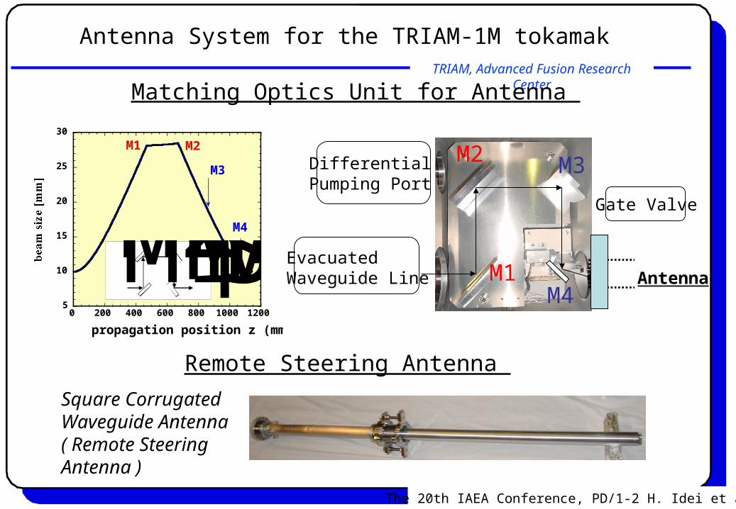
Antenna System for the TRIAM-1M tokamak TRIAM, Advanced Fusion Research Center
Gate Valve
Antenna
DifferentialPumping Port
EvacuatedWaveguide Line
5
10
15
20
25
30
0 200 400 600 800 1000 1200
propagation position z (mm)
M1 M2
M3
M4M1M2M3M4SteeringMirror
Matching Optics Unit for Antenna
M1
M2 M3
M4
Square CorrugatedWaveguide Antenna( Remote SteeringAntenna )
Remote Steering Antenna
The 20th IAEA Conference, PD/1-2 H. Idei et al.

TRIAM, Advanced Fusion Research Center
0.00
0.05
0.10
0.15
0.20
-5
0
5
10
15
20
25
30
-20 -10 0 10 20 30 40 50 60x [ mm ]
ωx=11mm
Rx=
218mmThe phase rapidly changes near the side lobe, therefore, the side lobe part is spread out from the main lobe along the propagation.
[ Ey Component: 15 degree steering case ]
Output Beam Analysis [ Output pattern & Steering Angle ]
Output Beam is analyzed using Moment Method to evaluate the beam center offset and the steering angle, and using Matching Coefficient to evaluate Gaussian Content.
The phase profile is flat near the beam center.The beam propagates along the measuring z-axis.
x
yz
15 degrees
The 20th IAEA Conference, PD/1-2 H. Idei et al.

TRIAM, Advanced Fusion Research Center
Analysis by Moment Method & Matching Coefficient
The n-th moment in the x direction is defined with the amplitude distribution A(x, y) as,
The dependence of the beam center position on the propagating position z can be written as,
,where k and are the wave number and the phase distribution.
Beam CenterFirst moment<x> = 8mm
Propagating slopeSteering Accuracy : -0.3 degree [ in main lobe ]
The complex amplitudes f , g are deduced from the intensity and phase distributions measured and calculated with the fitted wx and Rx in Gaussian Optics. The Gaussian content is evaluated as 0.85 for the output beam.
f , g: Complex amplitude Ae
The 20th IAEA Conference, PD/1-2 H. Idei et al.

TRIAM, Advanced Fusion Research Center
Transmission Efficiency
To evaluate the efficiency,the intensity patterns are integrated in the x-y plane at the low power test.
A dummy load is connectedthe enterance and the end of the antenna at the high power test. Dummy
load
The fractions containing the higher-order Hermite Gaussian modes [HGm0 modes (m=1-60)] in the imaging property calculation are consistent with those in the measurement.
0.0
0.2
0.4
0.6
0.8
1.0
0 5 10 15 20 25
Low power ExLow power EyHigh power ExCal.[HG00] EyCal.[HGm0] Ey
: m=0-60
Steering Angle [ degree ]
Tra
nsm
issi
on
Eff
icie
ncy
Trans. eff. : ~0.95
x
yz
The 20th IAEA Conference, PD/1-2 H. Idei et al.
The
rmal
dri
ft o
f IF
Am
p.

ECH / ECCD Experiments using Remote Steering Antenna on the TRIAM-1M tokamak
1. Mode Purity Control Experiment----- to optimize and confirm the incident polarization state----
2. O-mode Experiment 3. X-mode Experiment
The 20th IAEA Conference, PD/1-2 H. Idei et al.

Halo
TRIAM, Advanced Fusion Research Center
Mode Purity Control Experiment in Superposition to LHCD Plasma
The R cutoff radius Rcut is 0.870m. _The plasma center and the bulk resonance radii Raxis and Rres are 0.84m. The maximum resonance radius due to the Doppler shift effect RD is 0.865m.
No coupling area for incident X-mode componentIt is noted that it is ideal to confirm to the O-mode coupling for the incident beam.
R Cutoff
The 20th IAEA Conference, PD/1-2 H. Idei et al.
N//~0.22
0.700.750.800.850.900.951.00
-0.3-0.2-0.10.00.10.20.3
Rcut RD evaluated at R=RcutMajor Radius [m]N// at R = Rcut
Current Drive(CD) Window for X-mode
RaxisRcut RD
low field side ne = 0.8 x 10¹⁹ m-3 in the target LHCD plasma
Rcut >RD

05
101520
Δ Ip [kA]
+13 degree case
0.00.51.01.52.02.53.0 ΔIsx14(R0.79m)ΔIsx9(R0.84m)ΔIsx6(R0.88m)ΔIsx5(R0.89m)ΔIsx4(R0.9m)
-0.2 0 0.2 0.4 0.6 0.8 1 1.2
Δ ISX
[a.u.]
0.00.51.01.5
0 0.2 0.4 0.6 0.8 1
ΔIHx6(R0.79m)ΔIHx5(R0.81m)ΔIHx4(R0.84m)ΔIHx3(R0.86m)ΔIHx2(R0.89m)ΔIHx1(R0.91m)
Δ IHX
[a.u.]
Mode Purity for O-mode
Halo
TRIAM, Advanced Fusion Research Center
Mode Purity Control Experiment
The increase of the current comes from a coupling of Electron Cyclotron Wave to the LHCD plasma.
The 20th IAEA Conference, PD/1-2 H. Idei et al.
LH 60kW
~30kA
~0.8x10¹⁹m-3Raxis
ECH/ECCD 100kW
N//~0.22 Purity 1.0
Purity 1.0
Purity 1.0
Purity 1.0(center)
(center)
Ip
ne
SX
HX
OII

Halo
TRIAM, Advanced Fusion Research Center
Steering Angle Scan in the O-mode Experiment
The heating effect in an improvement of the LHCD efficiency is dominant.
The increased current ΔIp in the perpendicular injection is 18.3 kA.
The current drive efficiency ECHLH = neIpR/(PECHPLH) in the superposition is evaluated as 0.325 x 10¹⁹ A/Wm2.That is comparable to LH of 0.378 x 10¹⁹ A/Wm2 in the target LHCD plasma.
0.05.010.015.020.0
0.00.10.20.30.40.50.60.70.8
-0.2-0.10.00.10.2
-15-10-5051015
Ip [kA]Calculated Optical Depth τ
[ ]Ip kAτ [ :2 nex1019m-3; :700 ]Te eV
// =N at R Rres
[ ]Steering angle degree
The 20th IAEA Conference, PD/1-2 H. Idei et al.

TRIAM, Advanced Fusion Research Center
0.0
0.5
1.0
+ 16 degrees [co- injection] - 16 degrees [counter- injection]
0.75 0.8 0.85 0.9 0.95 [ ]R m
0.0
0.5
1.0
1.5 +16 [ - ]degrees co injection -16 [ ]degrees counter injection
Peaked ΔIHX Profile in the Co- Steering Case at the O-mode Injection
The peaked ΔIHX comes from the improvement of the LHCD efficiency due to increased electron temperature and density and a direct coupling into the forward fast electrons at between R=Rres and R=RD.
In the co- (+16 degrees) and counter- (-16 degrees) steering cases, the forward (v//>0) and backward (v//<0) fast electrons can be coupled with the incident wave between RD and Rres before the beam is absorbed by the bulk electrons.
The 20th IAEA Conference, PD/1-2 H. Idei et al.
2025303540
1.4 1.5 1.5 1.6 1.6 1.7 1.7 1.8 1.8
Ip [kA]
ECH ~ 100kW
Counter- injection[ -19 degrees ]
Co-injection [ +19 degrees ] ECCD
0.20.40.60.8
1.4 1.5 1.6 1.7 1.8HX Intensity at Center Code[ arb. unit ]
Co-injection [ +19 degrees ]
Counter- injection[ -19 degrees ]
Time [s] ECH ~ 100kW
Halo
TRIAM, Advanced Fusion Research Center
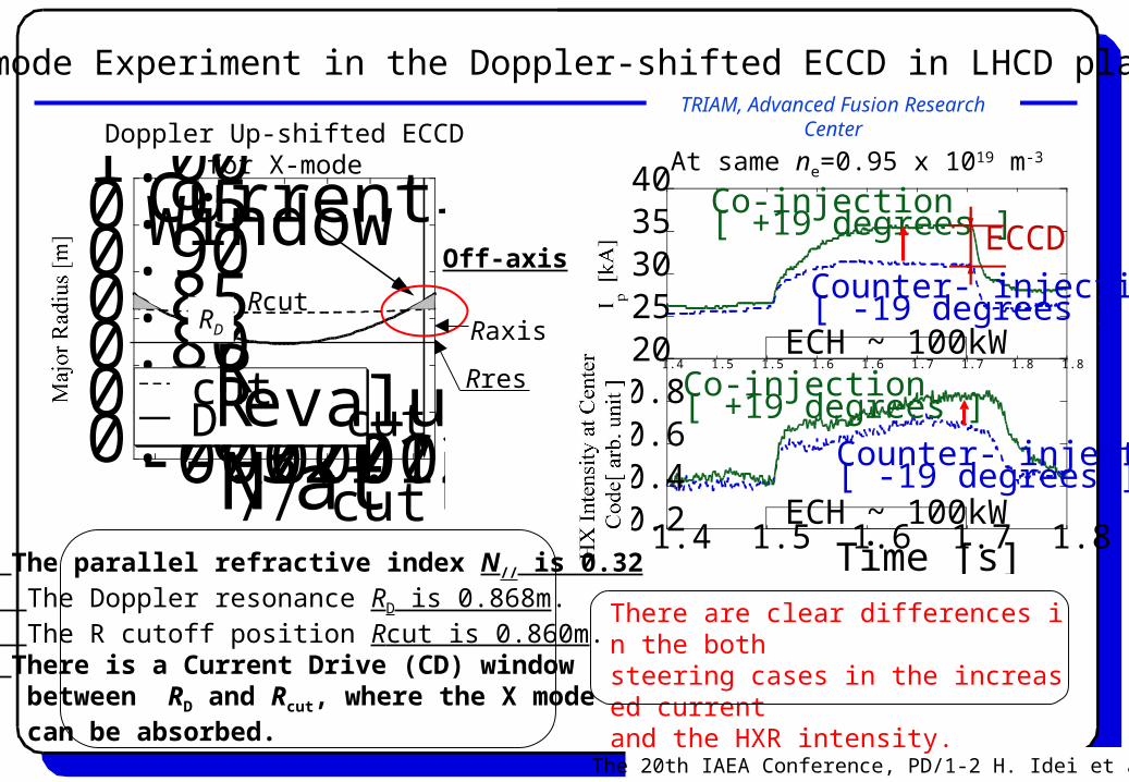
X-mode Experiment in the Doppler-shifted ECCD in LHCD plasma
The parallel refractive index N// is 0.32 The Doppler resonance RD is 0.868m. The R cutoff position Rcut is 0.860m. There is a Current Drive (CD) window between RD and Rcut, where the X mode can be absorbed.
The 20th IAEA Conference, PD/1-2 H. Idei et al.
At same ne=0.95 x 10¹⁹ m-3
There are clear differences in the both steering cases in the increased current and the HXR intensity.
0.700.750.800.850.900.951.00
-0.3-0.2-0.10.00.10.20.3 Rcut RD evaluated at R=Rcut
Major Radius [m]N// at R = Rcut
Current Drive(CD) Window for X-mode
Doppler Up-shifted ECCDfor X-mode
RD
Rres
RcutRaxis
Off-axis

Halo
TRIAM, Advanced Fusion Research Center
0.30
0.35
0.40
0.45
0.50
0.75 0.80 0.85 0.90 0.95R [ m ]
plasma center
CD Window
The hollow ΔIHX profile is observed with a peak at the CD window. It indicates the incident X-mode wave is coupled around R=0.86m.
The 20th IAEA Conference, PD/1-2 H. Idei et al.
0.0
0.2
0.4
0.6
0.8
1.0
-0.6 -0.4 -0.2 0.0 0.2 0.4 0.6 0.8 1.0p
//
10 keV
70 keV
Resonanceat R=0.86m p
// = γ/N
pThe possible energy range to be resonant with the incident X-mode at R=0.86m is evaluated as 10-60keV. The resonant energy range for the EC wave is consistent with that of the forward fast electrons by the LH wave.
ECCD in X-mode Coupling to Fast Electrons in LHCD plasma
ΔIp is due to the ECCD effect on a coupling for the forward fast electrons in the LHCD plasma.
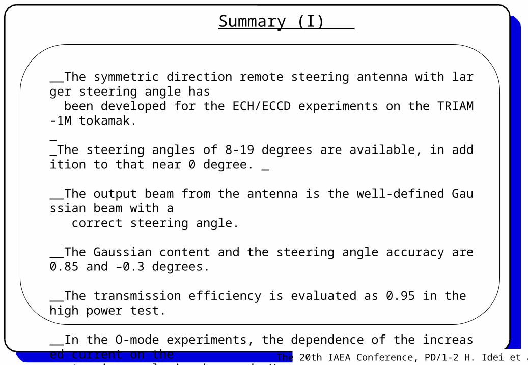
Summary (I)
The symmetric direction remote steering antenna with larger steering angle has been developed for the ECH/ECCD experiments on the TRIAM-1M tokamak. The steering angles of 8-19 degrees are available, in addition to that near 0 degree.
The output beam from the antenna is the well-defined Gaussian beam with a correct steering angle.
The Gaussian content and the steering angle accuracy are 0.85 and –0.3 degrees.
The transmission efficiency is evaluated as 0.95 in the high power test.
In the O-mode experiments, the dependence of the increased current on the steering angle is observed. However, the heating effect in an improvement of the LHCD efficiency, compared to the ECCD effect, is dominant.
The 20th IAEA Conference, PD/1-2 H. Idei et al.

In the X-mode experiment, there are clear differences in ΔIp and ΔIHX in the larger co- and counter- steering cases due to the ECCD effect on the coupling for the forward fast electrons in the energy range of 10-60keV at the medium density (1x10¹⁹m-3). The hollow profile of the HXR intensity increased by ECH/ECCD is observed at the CD window.
The resonant energy range is consistent with that of fast electron generated by the LH wave.
_The CD efficiency is roughly evaluated from the difference of the increased current (~ 5kA) between the co- and counter- steering cases as ten times smaller than that in LHCD.
Summary (II)
This is a first application of the remote steering antenna to the ECH/ECCD experiment.
The 20th IAEA Conference, PD/1-2 H. Idei et al.
The energy range of fast electrons coupled with EC wave is equivalent to that of resonant electrons for ECCD in high electron temperature plasmas at ITER.


![洪水ハザードマップ 柳生川 中文 - Toyohashi · Matsuba Shögakkö 9.3]' . Matsuba Köku Shiminkan Hanada Köban v/' Toyohashi Ekimae Köban Hanada Shögakkö Höjö Chügakkö](https://img.dokumen.tips/doc/110x75/60b7436a9fc015020517d8a6/fffffff-c-matsuba-shgakk-93-matsuba.jpg)