Embed Size (px)
Citation preview

October 13, 2011
Dr. Andrew Rawicz
School Of Engineering Science
Simon Fraser University
Burnaby, British Columbia
V5A 1S6
Re: ENSC 440 Function Specification for a Sleepwear Diagnostic System
Dear Dr. Rawicz,
Please find the attached Functional Specification Document for a Sleepwear Diagnostic System
(SDS) by NAPNEA. NAPNEA is developing a sensor-equipped shirt that quantifies physiological
phenomena that occur during sleep and that can be used to diagnose sleep apnea. The SDS will
provide an innovative and reliable solution to existing sleep apnea diagnosis limitations.
Our functional specification provides a set of high-level requirements for the system's
functionality. The document outlines specific objectives for various phases of product
development and will be used by all members of NAPNEA during the design, prototyping, and
testing stages. All supporting sections will help justify the capability and viability of the device.
NAPNEA is a well-rounded biomedical company comprised of five aspiring biomedical
engineers: Alex Manousiadis, Allison Chew, Ekin Nalbantoglu, Eleanor Li, and Jason Cheung.
While each member possesses a unique skill set, our fervent dedication to the biomedical
engineering field is unanimous.
If you have any inquiries or comments regarding this project, please feel free to contact
NAPNEA by phone at 604.808.9675 or by email at [email protected].
Sincerely,
Allison Chew
Chief Executive Officer
NAPNEA
Enclosed: Functional Specifications for a Sleep Apnea Diagnostic Shirt
ii
Functional Specification for a Sleepwear Diagnostic System
AllisonChew CEO AlexManousiadis CTO EkinNalbantoglu CAO
JasonCheung CRO EleanorLi CCO
ContactPerson Jason Cheung [email protected]
SubmittedTo Dr. Andrew Rawicz (ENSC 440) Mike Sjoerdsma (ENSC 305) School of Engineering Science Simon Fraser University
IssuedDate October 13, 2011
iii
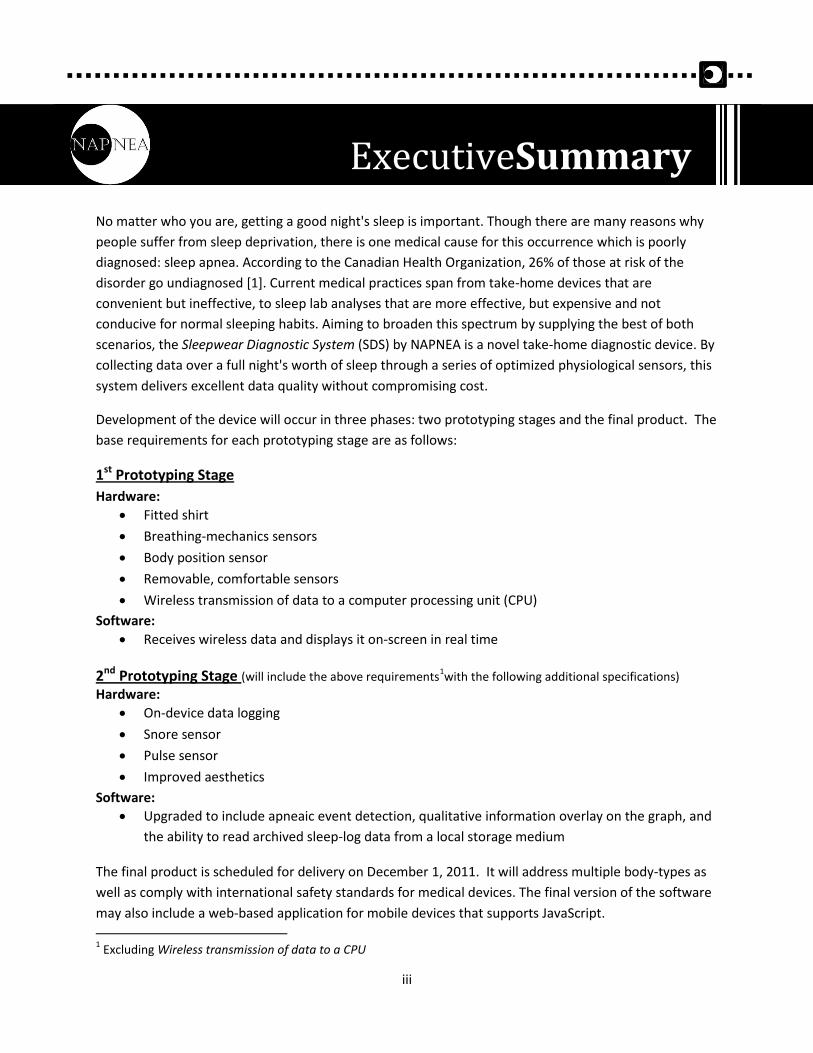
No matter who you are, getting a good night's sleep is important. Though there are many reasons why
people suffer from sleep deprivation, there is one medical cause for this occurrence which is poorly
diagnosed: sleep apnea. According to the Canadian Health Organization, 26% of those at risk of the
disorder go undiagnosed [1]. Current medical practices span from take-home devices that are
convenient but ineffective, to sleep lab analyses that are more effective, but expensive and not
conducive for normal sleeping habits. Aiming to broaden this spectrum by supplying the best of both
scenarios, the Sleepwear Diagnostic System (SDS) by NAPNEA is a novel take-home diagnostic device. By
collecting data over a full night's worth of sleep through a series of optimized physiological sensors, this
system delivers excellent data quality without compromising cost.
Development of the device will occur in three phases: two prototyping stages and the final product. The
base requirements for each prototyping stage are as follows:
1st Prototyping Stage
Hardware:
Fitted shirt
Breathing-mechanics sensors
Body position sensor
Removable, comfortable sensors
Wireless transmission of data to a computer processing unit (CPU)
Software:
Receives wireless data and displays it on-screen in real time
2nd Prototyping Stage (will include the above requirements1with the following additional specifications)
Hardware:
On-device data logging
Snore sensor
Pulse sensor
Improved aesthetics
Software:
Upgraded to include apneaic event detection, qualitative information overlay on the graph, and
the ability to read archived sleep-log data from a local storage medium
The final product is scheduled for delivery on December 1, 2011. It will address multiple body-types as
well as comply with international safety standards for medical devices. The final version of the software
may also include a web-based application for mobile devices that supports JavaScript.
1 Excluding Wireless transmission of data to a CPU
ExecutiveSummary
iv
Executive Summary ...................................................................................................................................... iii
List Of Figures .............................................................................................................................................. vii
Glossary ...................................................................................................................................................... viii
1. Introduction .............................................................................................................................................. 1
1.1 Scope ................................................................................................................................................... 1
1.2 Intended Audience .............................................................................................................................. 1
1.3 Classification ....................................................................................................................................... 1
2. System Requirements ............................................................................................................................... 2
2.1 System Overview................................................................................................................................. 2
2.1.1 Prototype I ................................................................................................................................... 2
2.1.2 Prototype II .................................................................................................................................. 3
2.2 General Requirements ........................................................................................................................ 4
2.3 Electrical Requirements ...................................................................................................................... 5
2.4 Physical Requirements ........................................................................................................................ 5
2.5 Environmental Requirements ............................................................................................................. 5
2.6 Reliability and Durability ..................................................................................................................... 5
2.7 Safety Requirements ........................................................................................................................... 6
2.8 Performance Requirements ................................................................................................................ 6
2.9 Usability Requirements ....................................................................................................................... 6
2.10 Standards .......................................................................................................................................... 6
3. Shirt Requirements ................................................................................................................................... 7
3.1 General Requirements ........................................................................................................................ 7
3.2 Physical Requirements ........................................................................................................................ 7
4. Sensor Requirements ................................................................................................................................ 8
4.1 General Requirements ........................................................................................................................ 8
4.2 Stretch Sensor Requirements ............................................................................................................. 8
4.3 Position Sensor Requirements ............................................................................................................ 8
TableOfContents

v
4.4 Snore Sensor Requirements ................................................................................................................ 8
4.5 Pulse Rate Sensor Requirements ........................................................................................................ 8
5. Electronic Infrastructure ........................................................................................................................... 9
5.1 General Requirements ........................................................................................................................ 9
5.2 Physical Requirements ........................................................................................................................ 9
6. Software .................................................................................................................................................. 10
6.1 Embedded Software Requirements .................................................................................................. 10
6.2 Data Analysis Software Requirements .............................................................................................. 10
7. User Documentation ............................................................................................................................... 11
8. System Test Plan ..................................................................................................................................... 12
8.1 Individual Component Testing .......................................................................................................... 12
8.1.1 Microcontroller Unit (MCU) ....................................................................................................... 12
8.1.2 Position Sensor ........................................................................................................................... 12
8.1.3 Stretch Sensors .......................................................................................................................... 12
8.1.4 Snore Sensor .............................................................................................................................. 12
8.1.5 Pulse Sensor ............................................................................................................................... 13
8.1.6 Battery ........................................................................................................................................ 13
8.1.7 Sleepwear Shirt .......................................................................................................................... 13
8.2 Sensor Placement Optimization ........................................................................................................ 13
8.2.1 Sensor Location .......................................................................................................................... 13
8.2.2 Sensor Washability ..................................................................................................................... 13
8.3 Units Integrated ................................................................................................................................ 14
8.3.3 Integration of Sensors with Sleepwear Unit .............................................................................. 14
8.3.2 MCU interface with Multiplexor ................................................................................................ 14
8.3.3 MCU interface with Clock .......................................................................................................... 14
8.3.4 MCU interface with Data Logger ................................................................................................ 14
8.3.5 Electronic Infrastructure ............................................................................................................ 14
8.3.6 Sleepwear Shirt .......................................................................................................................... 14
8.4 Qualitative Testing ............................................................................................................................ 15
8.4.1 Usability...................................................................................................................................... 15
8.4.2 Typical User Scenarios ............................................................................................................... 15
8.4.3 Collecting a Full-Night’s Data ..................................................................................................... 15
vi
8.5 Software Testing ............................................................................................................................... 15
8.5.1 Usability...................................................................................................................................... 15
8.5.2 Algorithm ................................................................................................................................... 16
Conclusion ................................................................................................................................................... 17
References .................................................................................................................................................. 18
vii
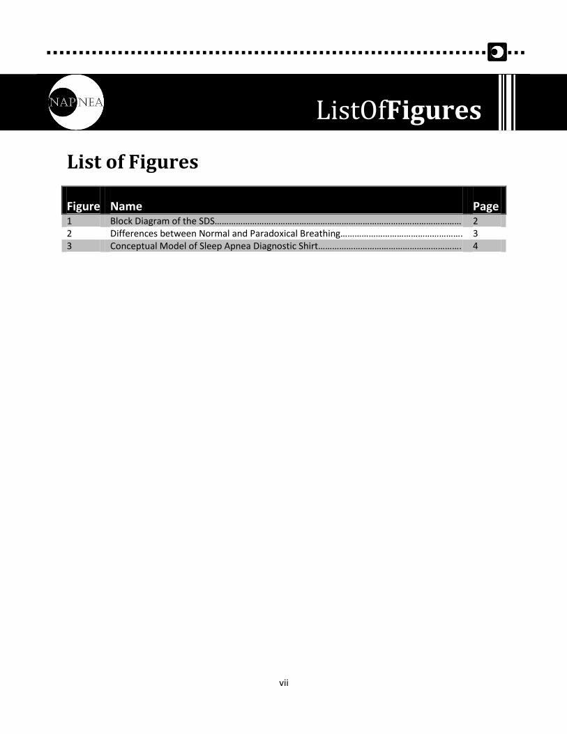
List of Figures
Figure Name Page 1 Block Diagram of the SDS…………………………………………………………………………………………… 2 2 Differences between Normal and Paradoxical Breathing……………………………………………. 3 3 Conceptual Model of Sleep Apnea Diagnostic Shirt……………………………………………………. 4
ListOfFigures
viii
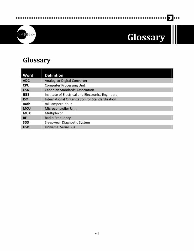
Glossary
Word Definition ADC Analog-to-Digital Converter CPU Computer Processing Unit CSA Canadian Standards Association IEEE Institute of Electrical and Electronics Engineers ISO International Organization for Standardization mAh milliampere-hour MCU Microcontroller Unit MUX Multiplexor RF Radio Frequency SDS Sleepwear Diagnostic System USB Universal Serial Bus
Glossary

1
The Sleepwear Diagnostic System(SDS) is a fitted shirt embedded with various electronics and sensors
and is intended to be worn by patients during a full night’s sleep. It acquires and logs physiological data,
which may include breathing mechanics, body position, snoring, and pulse rate. This data is analyzed by
a clinician with a custom software application that can identify sleep apnea symptoms and diagnose
patients. The requirements for the SDS, as proposed by NAPNEA, are described in this functional
specification document.
1.1 Scope This document lists the functional requirements that must be met by the SDS. These requirements will
fully explain the proof-of-concept and final production devices by describing in detail what the device
will do, how the device will work, how the device will interact with the user, and how the device will
look. The functional requirements will drive the design of the SDS and will be traceable in future design
documents.
1.2 Intended Audience The functional specification is written for all members of NAPNEA to use as a reference throughout the
design and development process of this project. It will allow the design goals to be easily accessible in
one document and also will aid in resolving design conflicts or performance-related issues, should they
arise. This document will further be used to determine whether the amount of progress being made is
sufficient to fulfill NAPNEA's ultimate goals.
1.3 Classification Throughout this document, the following convention shall be used to denote functional requirements:
[ST-##-X]
ST = Section Title Abbreviation
## = Functional Requirement Number
X = Functional Requirement Priority - A, B, C
(A) Functional requirement for first prototype unit
(B) Functional requirement for second prototype unit
(C) Functional requirement for production unit
1. Introduction
2
The general system requirements of the SDS proof-of-concept and final production models are
presented below. Specific subsystem requirements can also be found in the following sections.
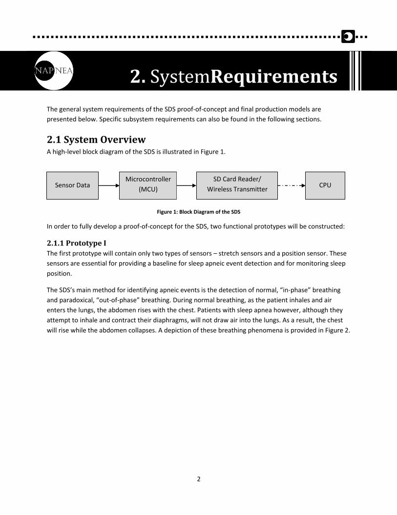
2.1 System Overview A high-level block diagram of the SDS is illustrated in Figure 1.
Figure 1: Block Diagram of the SDS
In order to fully develop a proof-of-concept for the SDS, two functional prototypes will be constructed:
2.1.1 Prototype I
The first prototype will contain only two types of sensors – stretch sensors and a position sensor. These
sensors are essential for providing a baseline for sleep apneic event detection and for monitoring sleep
position.
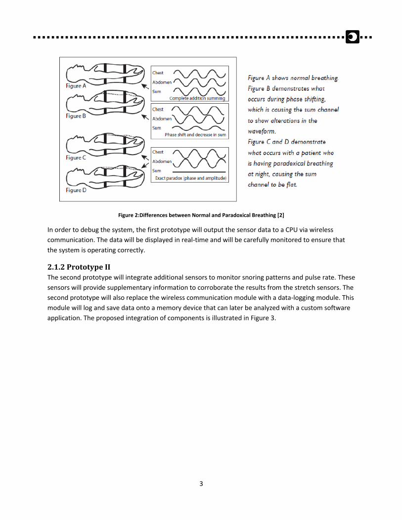
The SDS’s main method for identifying apneic events is the detection of normal, “in-phase” breathing
and paradoxical, “out-of-phase” breathing. During normal breathing, as the patient inhales and air
enters the lungs, the abdomen rises with the chest. Patients with sleep apnea however, although they
attempt to inhale and contract their diaphragms, will not draw air into the lungs. As a result, the chest
will rise while the abdomen collapses. A depiction of these breathing phenomena is provided in Figure 2.
Sensor Data Microcontroller
(MCU) CPU
SD Card Reader/
Wireless Transmitter
2. SystemRequirements
3
Figure 2:Differences between Normal and Paradoxical Breathing [2]
In order to debug the system, the first prototype will output the sensor data to a CPU via wireless
communication. The data will be displayed in real-time and will be carefully monitored to ensure that
the system is operating correctly.
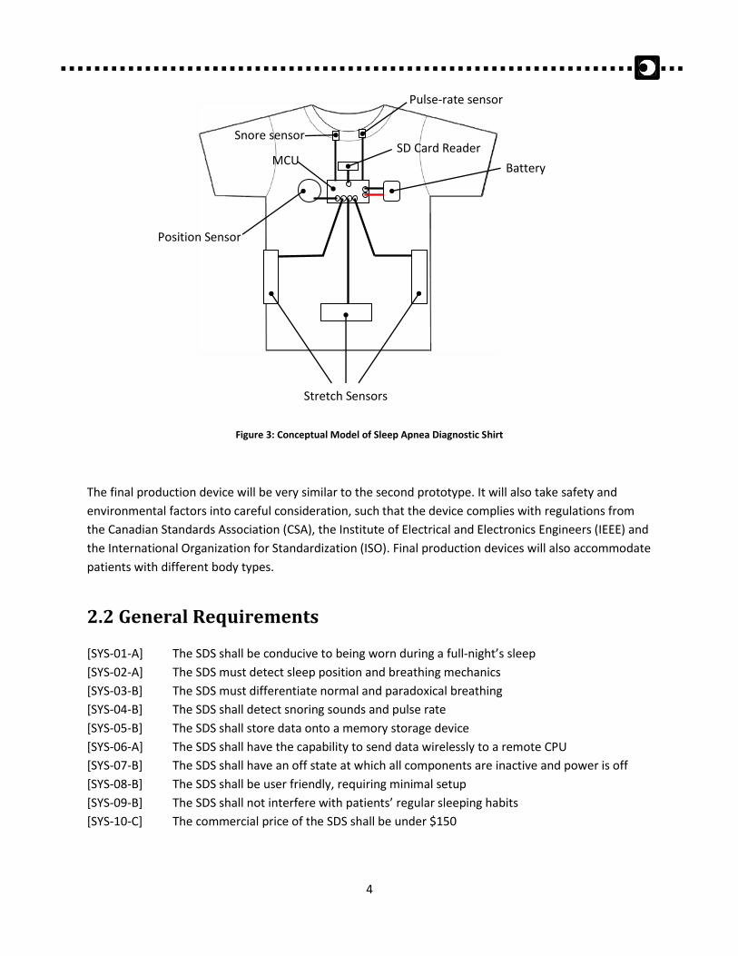
2.1.2 Prototype II
The second prototype will integrate additional sensors to monitor snoring patterns and pulse rate. These
sensors will provide supplementary information to corroborate the results from the stretch sensors. The
second prototype will also replace the wireless communication module with a data-logging module. This
module will log and save data onto a memory device that can later be analyzed with a custom software
application. The proposed integration of components is illustrated in Figure 3.
4
Figure 3: Conceptual Model of Sleep Apnea Diagnostic Shirt
The final production device will be very similar to the second prototype. It will also take safety and
environmental factors into careful consideration, such that the device complies with regulations from
the Canadian Standards Association (CSA), the Institute of Electrical and Electronics Engineers (IEEE) and
the International Organization for Standardization (ISO). Final production devices will also accommodate
patients with different body types.
2.2 General Requirements
[SYS-01-A] The SDS shall be conducive to being worn during a full-night’s sleep
[SYS-02-A] The SDS must detect sleep position and breathing mechanics
[SYS-03-B] The SDS must differentiate normal and paradoxical breathing
[SYS-04-B] The SDS shall detect snoring sounds and pulse rate
[SYS-05-B] The SDS shall store data onto a memory storage device
[SYS-06-A] The SDS shall have the capability to send data wirelessly to a remote CPU
[SYS-07-B] The SDS shall have an off state at which all components are inactive and power is off
[SYS-08-B] The SDS shall be user friendly, requiring minimal setup
[SYS-09-B] The SDS shall not interfere with patients’ regular sleeping habits
[SYS-10-C] The commercial price of the SDS shall be under $150
Stretch Sensors
Position Sensor
Battery
SD Card Reader MCU
Snore sensor
Pulse-rate sensor

5
2.3 Electrical Requirements
[SYS-11-A] The power supply must be sufficient to power all electronic components simultaneously
[SYS-12-A] The power supply must last for at least 10 hours
[SYS-13-A] The power supply shall be rechargeable
[SYS-14-A] Electronic components shall not require more than 850 milliampere-hour (mAh) of
charge
2.4 Physical Requirements
[SYS-15-A] The SDS shall be a single wearable unit in the form of a shirt
[SYS-16-A] The components embedded in the shirt shall not negatively affect patient comfort
[SYS-17-A] Embedded components shall be inconspicuous to the patient
[SYS-18-B] Embedded components must not shift while the SDS is in use
[SYS-19-B] Components that will degrade in a washing machine must be removable
[SYS-20-B] The SDS shall be washable upon removal of non-washable parts
[SYS-21-C] Different SDS units shall be made to accommodate different body types and genders
2.5 Environmental Requirements
[SYS-22-C] The SDS shall meet performance requirements when used indoors at normal room
temperatures between 10˚C to 30˚C
[SYS-23-C] Electronic components of the SDS must dissipate minimal amounts of heat
[SYS-24-C] Electronic components of the SDS shall not interfere with other household electronics
[SYS-25-C] Household electronics shall not interfere with the electronic components of the SDS
[SYS-26-A] The SDS shall be able to wirelessly transmit data to a distance of at least 10 feet in a
household environment
2.6 Reliability and Durability
[SYS-27-C] The SDS shirt shall be resistant to any damage caused during normal sleep movement
wear and tear
[SYS-28-C] The SDS shirt shall be as durable or more durable as shirts on the market without
additional electronic components
[SYS-29-C] The electronic components must continue to operate properly even when exposed to
humid environments (i.e. sweat moisture)
[SYS-30-C] In the case of electronic component failure or malfunction, the electronic components
shall be easily replaceable
[SYS-31-A] Data transmission or logging shall be able to continue for a minimum of 10 hours for
each session
6
2.7 Safety Requirements
[SYS-32-C] The device battery must not overheat and cause discomfort to the user
[SYS-33-C] The SDS shirt shall not be so tight as to cut off circulation to the user
[SYS-34-C] The electronic components or any part of the SDS must not have any sharp edges
[SYS-35-C] The power supply to the electronic components must not have a high enough voltage to
cause an electric shock
[SYS-36-B] The electronic components must be secure and not protruding from under the
sleepwear
[SYS-37-B] All wires and electronic components must be well-insulated and/or housed within
male/female headers
2.8 Performance Requirements
[SYS-38-A] Data logging or transmission shall not have noticeable latency
[SYS-39-A] Sensors shall produce data with high fidelity to the amount they are stretched
2.9 Usability Requirements
[SYS-40-B] Removable components shall be clearly identifiable with the use of labels or affordances
[SYS-41-B] The sensors shall be easy to remove and replace
[SYS-42-B] The state of the SDS (on/off) shall be clearly recognized by the user
[SYS-43-B] The user shall be able to assemble the system rapidly
[SYS-44-A] The SDS shall provide the user with the familiarity and intuitiveness of a standard shirt
2.10 Standards
[SYS-45-C] The SDS must conform to standards outlined by the Electrical and Information
Technology & Communication sections of the Canadian Standards Association (CSA) [3]–
[4]
[SYS-46-C] The SDS must conform to standards outlined by the Canadian division of the Institute of
Electrical and Electronics Engineers (IEEE) [5] – [6]
[SYS-47-C] The SDS must conform to standards outlined by the International Organization for
Standardization (ISO): Sections 13: Environment. Health Protection. Safety, 31:
Electronics, 33: Telecommunications. Audio and Video Engineering, 59: Textile and
Leather Technology, and 61: Clothing Industry. [7]

7
The main part of the SDS that the patient has direct contact with is the sleepwear shirt. The patient can
immediately establish a familiar association with the SDS due to the commonality of the clothing,
increasing the device’s usability. The shirt also houses all electronics and holds the electronic
infrastructure in place.
The following shirt specifications should be met in order to maximize usability, aesthetics, comfort, and
functionality.
3.1 General Requirements
[SH-01-A] The sleepwear shirt must hold the electronic infrastructure in place such that the
electronics do not easily shift
[SH-02-A] The material of the sleepwear shirt shall allow for alterations and the addition of
embedded electronics
[SH-03-A] The sleepwear shirt shall be off-the-shelf and available through specialty retailers
[SH-04-C] The sleepwear shirt shall be custom-made and mass-produced to lower costs
3.2 Physical Requirements
[SH-05-A] The sleepwear shirt shall be short-sleeved or sleeveless
[SH-06-A] The sleepwear shirt shall be a fitted compression shirt
[SH-07-A] The sleepwear shirt shall be breathable, preventing the patient from sweating
excessively
[SH-08-A] The sleepwear shirt shall be comfortable
[SH-09-A] The sleepwear shirt shall be washable
[SH-10-A] The sleepwear shirt shall be capable of stretching in the horizontal and vertical
directions
3. ShirtRequirements

8
4.1 General Requirements
[SR-01-A] The analog sensor data shall be able to be accurately converted by a 10-bit analog-to-
digital converter (ADC) without significant loss of data
[SR-02-A] The sensors and placement of sensors shall not cause discomfort to the user
[SR-03-B] The sensors must be removable from the shirt if they degrade after washing
4.2 Stretch Sensor Requirements
[SR-04-A] The stretch sensors must detect deformation when stretched
[SR-05-A] The stretch sensors shall have a linear relationship between its output voltage and
deformation magnitude
[SR-06-A] The stretch sensors shall be placed at locations on the chest and abdomen where
mechanical deformation is the most significant
[SR-07-A] The stretch sensors shall operate correctly regardless of orientation
[SR-08-B] The stretch sensors shall accurately detect deformation whether the user is sleeping on
their back, side, or front
4.3 Position Sensor Requirements
[SR-09-A] The position sensor shall detect acceleration in three dimensions with little noise or
error
[SR-10-A] The position sensor shall be easily calibrated
4.4 Snore Sensor Requirements
[SR-11-B] The snore sensor shall detect moderately loud noises from a distance of at least six cm
[SR-12-B] The snore sensor must accurately record snoring sounds
[SR-13-B] The snore sensor shall be placed in a position where it can easily be integrated into the
sleepwear shirt
[SR-14-B] The snore sensor shall perform with minimal interference from ambient noise
4.5 Pulse Rate Sensor Requirements
[SR-15-B] The pulse rate sensor must accurately detect the patient’s pulse rate without significant
interference
4. SensorRequirements
9
The power supply and wiring will provide the microcontroller with electricity and connect it to the
sensors embedded within the sleepwear shirt. Though the power level of the circuit is low, it is crucial
that no contact can occur between the circuitry and the user, even during heavy movement.
5.1 General Requirements
[EI-01-A] Wiring must not cause harm to the wearer due to a short circuit with the user’s body
[EI-02-A] The power supply must be sufficient enough to log a complete night's sleep for wearers,
including marathon sleepers (over eight hours)
[EI-03-B] The power supply shall be recharged using a wall supply or universal serial bus(USB)-to-
CPU connection
[EI-04-B] Wiring shall maintain conductivity after washing
5.2 Physical Requirements
[EI-05-A] The electronic infrastructure shall be hidden from the user by means of a soft enclosure
that does not alter the comfort and appearance of the shirt
[EI-06-C] Sensor wiring shall be embedded within the fabric of the shirt
[EI-07-A] Wiring shall be as short as possible
[EI-08-B] The electronic infrastructure shall not protrude outwards from the inner surface of the
shirt to cause discomfort to the wearer
[EI-09-B] A power source that is both small and contains adequate output for the hardware shall
be selected
5. ElectronicInfrastructure
10
The software portion of the SDS is split into two parts. The first part is the embedded software that
comes with the microcontroller; it will be used as a middle point for collecting data from the stretch
sensors. The second software component is computer-based, and will be used to process and analyze
the data.
6.1 Embedded Software Requirements
[SW-01-A] The MCU shall have an on and off state, at which the SDS is collecting data or powered
off, respectively
[SW-02-A] The user shall receive feedback on which state the MCU is at
[SW-03-A] The embedded software shall wirelessly transmit data to a data analysis software
program
[SW-04-B] The embedded software shall log data onto a memory storage unit, where it will be later
analyzed by a data analysis software program
[SW-05-B] The embedded software shall keep track of time (day, hour, minute, second)
[SW-06-C] Software must operate properly following a power failure
6.2 Data Analysis Software Requirements
[SW-07-A] The user interface shall be graphic-based and provide user prompts
[SW-08-A] The program to analyze data shall be straightforward and intuitive to the user
[SW-09-A] The program shall display the data in an easy-to-read and understandable format
[SW-10-B] The display shall prominently show events of interest
[SW-11-B] Failsafe features must include error-checking to ensure the sleepwear is worn properly
[SW-12-C] The program must be able to run on various devices and platforms
[SW-13-C] This program must be included with the SDS and downloadable at no extra cost
[SW-14-C] Software must operate properly following a power failure
6. Software

11
[UD-01-A] The user documentation shall be provided for two user groups: healthcare professionals
and patients. Language and depth of the document shall reflect the ability and interest
of each group
[UD-02-A] The documentation shall be written in English
[UD-03-B] A "Quick-Start" guide shall be made available additionally
[UD-04-C] An online version of documentation shall be made available additionally
7. UserDocumentation
12
The System Test Plan will be divided into five in-depth testing stages: individual component testing,
sensor optimization, integrated unit testing, qualitative testing, and software testing. These stages will
ensure that the hardware and software components function correctly on their own and as a unit, and
that the prototypes fulfill the objectives of the SDS to operate as a reliable diagnostic tool.
8.1 Individual Component Testing Each of the components that make up the SDS must be tested for their basic functionality to ensure that
each is able to fully perform without error before being integrated into the system.
8.1.1 Microcontroller Unit (MCU)
The MCU will be tested to verify that its resolution allows the sensor data to contain enough detail for
diagnosis. In order to assess the MCU’s ability to establish a two-way communication with the CPU for
programming, the MCU will be connected to the CPU via USB. The MCU will be tested to verify that it
can execute embedded software properly by uploading to it a simple program and evaluating its
performance. Additionally, the radio frequency (RF) connection between the MCU and the CPU will be
tested.
8.1.2 Position Sensor
The position sensor’s ability to detect acceleration in three dimensions with little noise or error will be
tested by moving the electronic component along three axial directions (x, y, z) and verifying that the
resulting data corresponds to the movement. This testing process will also be necessary for the sensor’s
calibration, in which the degree of rotation from the origin (lying on the back, face-up) will be calculated.
8.1.3 Stretch Sensors
To test the stretch sensors, the individual sensors will first be attached to a digital multimeter in order to
observe the input-output responses; this will show its ability to detect physical deformation. The stretch
sensors must also be tested to verify that they can accurately detect deformation with a 10-bit-
resolution MCU. Moreover, a simple data acquisition program in LabView will ensure that the data’s
accuracy is sufficient. Finally, the linear range of the stretch sensors will be tested by deforming the
sensors a certain length and observing both the change in output and at which length the input-output
relationship loses linearity.
8.1.4 Snore Sensor
During different simulated sleeping scenarios, data will be collected from the snore sensor circuit placed
at least six centimeters from the face. The sensor’s sensitivity to snore volume and ambient noise (i.e. a
person moving around in bed, the slight movement of the shirt, and the heartbeat) will then be tested
against different snoring noise ranges and in different environments.
8. SystemTestPlan
13
8.1.5 Pulse Sensor
The pulse sensor will be tested for its accuracy and ability to operate with physical interference. This will
be accomplished by placing the sensor on the body and verifying if the output data matches the test
subject’s pulse. The data accuracy will also be observed when the pulse sensor is lightly hit, when the
tester is pressed up against a surface, and when the tester is in constant, uncontrolled motion.
8.1.6 Battery
The battery will be tested to determine the amount of time it can power the MCU. Once its lifetime is
estimated, a more in-depth test will be done to define what percentage of that time the voltage
provided is a constant 3.7V. This value will be compared to the value on the battery’s data sheet.
8.1.7 Sleepwear Shirt
The sleepwear shirt will be tested for its ability to stretch in the horizontal and vertical directions. The
sleepwear shirt will also be tested for comfort and breathability by verifying that the user can move
freely in the shirt and does not sweat excessively in the shirt.
8.2 Sensor Placement Optimization Sensor placement is of paramount importance to ensure that the collected data is of prime quality and
accuracy. Sensor placement optimization testing will be performed on each sensor to determine optimal
location and performance standards.
8.2.1 Sensor Location
To determine the optimal locations for the stretch sensors, various positions and orientations on the
torso will be tested for greatest mechanical deformation while breathing. This will be done by placing
the sensors on various locations on the chest, side, back, and stomach and graphing the sensor output
data after three even and timed deep breaths (inhalation and exhalation). Breathing will be performed
while lying down on the back, sides, and front. Both normal breathing and simulated apneic breathing
will be tested. The graphs will then be judged by the members of NAPNEA in a “blind test” (where the
graphs’ corresponding sensor positions are unknown to the adjudicator) based on the detection of in-
phase and paradoxical breathing, accurate detection of breathing mechanics regardless of sleeping
position, and magnitude of the sensors’ response.
To determine the optimal location for the snore sensor, different locations will be tested while snoring
noises are simulated. The graphed output data will allow us to see where the best signal is recorded and
determine the optimal snore sensor placement. The chosen location must allow the sensor to be easily
integrated into the shirt, provide comfort for the patient, and minimize/eliminate additional setup.
Likewise, similar tests will also be performed on the pulse sensors to determine the optimal location for
accurately detecting pulse rate.
8.2.2 Sensor Washability
After use, the shirt will require washing. Therefore, washability tests will be performed to evaluate if
there is any change in the sensors’ performance by measuring and comparing the output of the sensors
14
before and after washes. Hand washing, machine washing, and machine washing with fabric softener
will all be tested to verify their effect on the sensitivity and performance of the sensors. With the results
of this test, it will be determined whether the sensors can be directly sewn onto the shirt or if they
require removal.
8.3 Units Integrated Once we have tested and ensured the individual components are operating as they should, tests for full
functionality as a unit will commence. The following components should work together.
8.3.3 Integration of Sensors with Sleepwear Unit
When the sensors are integrated with the sleepwear shirt and MCU, the system will be tested to verify
that the MCU can receive sensor data without latency or data loss. During these tests, the MCU will
output data wirelessly to a custom CPU application, which will display a graph of the sensor data in real
time. The graphs will be analyzed to confirm the operation of the MCU as well as to validate the location
and placement of the sensors.
8.3.2 MCU interface with Multiplexor
The sensor outputs will be connected to a multiplexor (MUX) for sequential output to the analog-to-
digital converter (ADC). The interface between the MCU and multiplexor will be tested for its ability to
successfully and rapidly select inputs and give desired outputs.
8.3.3 MCU interface with Clock
While the MCU is receiving sensor data, it will be simultaneously receiving time information from an
external real-time clock. The interface between the MCU and clock will be tested for its ability to keep
track of time and synchronize the time data with the sensor data. The tests will verify that the MCU can
accurately receive day, hour, minute, and second information.
8.3.4 MCU interface with Data Logger
Once the MUX selects the correct sensor and time data, all data will be stored onto a memory storage
device. The integration of the MCU and the data logger will be tested to verify that the data can be
stored in an organized manner, with separate files and/or folders, while being powered with a low-
voltage battery. The files should contain sequential sensor and time data that can be easily interpreted
by a CPU. The testing process will also ensure the unit stays powered for extended periods of time
without failure.
8.3.5 Electronic Infrastructure
The electronic infrastructure of the system will be tested for its ability to maintain constant connectivity
and its ability to maintain repeatability and consistency after being washed. The electronic hardware
and stretch sensors will also be tested for easy removal.
8.3.6 Sleepwear Shirt
The sleepwear shirt will be tested for its ability to provide comfort to the patient while integrated with
electronics. The shirt should also be tight enough so that the sensors do not shift during breathing
15
detection. Furthermore, the shirt will also be tested for durability after washing (once all un-washable
components are removed).
8.4 Qualitative Testing For each prototype, the SDS will be tested for ease-of-setup for the patient. The patient should be able
to put the shirt on, turn on the power, and sleep. The SDS will also be tested for accuracy and quality of
data.
8.4.1 Usability
Throughout the design process, the engineers of NAPNEA will be designing a shirt with the user in mind.
Testing will evaluate the SDS’s ease of use, aiming for a shirt that requires minimal patient setup. Once a
model close to the end-product is available, the shirt will be worn for a full-night’s sleep, testing all
aspects of the shirt from intuitiveness to comfort. This will be discussed in more detail in the “Collecting
a Full-Night’s Data” section below.
8.4.2 Typical User Scenarios
The typical user scenarios will be tested to survey how the system will function during a night’s sleep
before a real night-long data collection. The shirt will be tested with the user lying on their back, side,
and front while breathing normally. Sleep apnea will then be simulated by covering the tester’s nose and
mouth and asking them to inhale. Lastly, the two sets of data collected (baseline and apneaic) will be
compared to see if adjustments need to be made.
8.4.3 Collecting a Full-Night’s Data
The overnight sleep tests will check robustness of the system by determining unfavourable glitches like
unintentional power-offs. Results of these tests will also show if data is successfully loaded onto the SD
card while ideal information collected should show that the sensors did not shift during the night nor did
the system turn off at any point. It is also important that the data is accurately synchronized with time
(i.e. day, hour, minute, second). Furthermore, to guarantee complete exactitude, these overnight tests
will be performed by people not involved in the design process to get outside feedback on the usability
of the shirt.
8.5 Software Testing Once we have tested and verified that the components are operating correctly as one unit, software
testing will need to take place.
8.5.1 Usability
The user will be considered throughout the design of the software. Thus, the interface will be kept as
simple and intuitive as possible and the initial software testing will be done by the members of NAPNEA
as the software is being built. Once a version of the software that is close to the end-product is
available, people uninvolved in the software design process (i.e. friends, family, Dr. Najib Ayas) will be
asked to evaluate the software for its ease-of-use and to point out problems that may have been
16
overlooked by the creators. The final software should be interactive and intuitive. Buttons, menus and
display layouts will be evaluated as well as features such as saving, loading and viewing data and graphs
that can be scrolled through, enlarged, and zoomed into and out of.
8.5.2 Algorithm
The algorithm will be tested for its ability and accuracy to zone in on apneic events based on sensor
data, displayed breathing phase data, sleep position, snore data, and pulse rate. The algorithm should
also display the day and time of data collection, accurate to the second.
17
NAPNEA is excited to develop the Sleepwear Diagnostic System as a potential new golden standard for
sleep apnea diagnostics. In order to realize our ambitions, this functional specification document will
provide the engineers of NAPNEA with a meticulous set of guidelines and requirements that should be
fulfilled during the design, implementation, and testing stages of the SDS. With a clear plan and
definitive goals for each stage of development, NAPNEA will be able to produce a high-quality, reliable,
and innovative tool to greatly benefit the healthcare industry.
Conclusion
18
[1] Public Health Agency of Canada. (2010, Dec 10). What is the Impact of Sleep Apnea on Canadians.
[Online]. Available: http://www.phac-aspc.gc.ca/cd-mc/sleepapnea-apneesommeil/ff-rr-2009-
eng.php [Accessed: 2011, Sep 20].
[2] Phillips Respironics. (June 2009). The Sleep Technician Guide. [Online]. Available:
http://global.respironics.eu/pdf/Sleep_Technician_Guide.pdf [Accessed: 2011, Oct 12].
[3] Canadian Standards Association. (2011). Electrical. [Online], Available:
http://www.csa.ca/cm/ca/en/standards [Accessed: Oct. 5, 2011]
[4] Canadian Standards Association. (2011). Information Technology and Communications. [Online],
Available: http://www.csa.ca/cm/ca/en/standards [Accessed: Oct. 5, 2011]
[5] IEEE Standards Association. (2010). Wired and Wireless. [Online], Available:
http://standards.ieee.org/ [Accessed: Oct. 5, 2011]
[6] IEEE Standards Association. (2010). Consumer Electronics. [Online], Available:
http://standards.ieee.org/ [Accessed: Oct. 5, 2011]
[7] International Organization for Standardization. (2011). ISO Standards by ICS. [Online], Available:
http://www.iso.org/iso/iso_catalogue/catalogue_ics.htm [ Accessed: Oct. 5, 2011]
References

19
NAPNEA SIMON FRASER UNIVERSITY,
8888 UNIVERSITY DR. BURNABY, BC CANADA