Embed Size (px)
Citation preview

DOT HS 812 573 August 2018
Functional Safety Assessment of an Automated Lane Centering System

Notice
This document is disseminated under the sponsorship of the U.S. Department of Transportation, National Highway Traffic Safety Administration, in the interest of information exchange. The opinions, findings, and conclusions expressed in this publication are those of the authors and not necessarily those of the Department of Transportation or the National Highway Traffic Safety Administration. The U.S. Government assumes no liability for use of the information contained in this document.
This report does not constitute a standard, specification, or regulation.
If trade or manufacturers’ names or products are mentioned, it is because they are considered essential to the object of the publications and should not be construed as an endorsement. The United States Government does not endorse products or manufacturers.
Suggested APA Format Citation:
Becker, C., Yount, L., Rosen-Levy, S., & Brewer, J. (2018, August). Functional safety assessment of an automated lane centering system (Report No. DOT HS 812 573). Washington, DC: National Highway Traffic Safety Administration.

i
REPORT DOCUMENTATION PAGE Form Approved OMB No.0704-0188
Public reporting burden for this collection of information is estimated to average 1 hour per response, including the time for reviewing instructions, searching existing data sources, gathering and maintaining the data needed, and completing and reviewing the collection of information. Send comments regarding this burden estimate or any other aspect of this collection of information, including suggestions for reducing this burden, to Washington Headquarters Services, Directorate for Information Operations and Reports, 1215 Jefferson Davis Highway, Suite 1204, Arlington, VA 22202-4302, and to the Office of Management and Budget, Paperwork Reduction Project (0704-0188), Washington, DC 20503. 1. AGENCY USE ONLY (Leave blank) 2. REPORT DATE
August 2018 3. REPORT TYPE AND DATES COVERED July 2015 – October 2016
4. TITLE AND SUBTITLEFunctional Safety Assessment of an Automated Lane Centering System
5. FUNDING NUMBERS Intra-Agency Agreement DTNH22-14-V-00136 51HS6CA100
6. AUTHORsChristopher Becker, Larry Yount, Shane Rozen-Levy, and John Brewer 7. PERFORMING ORGANIZATION NAME AND ADDRESSJohn A. Volpe National Transportation Systems Center Cambridge, MA 02142
8. PERFORMING ORGANIZATIONREPORT NUMBER DOT-VNTSC-NHTSA-17-01
9. SPONSORING/MONITORING AGENCY NAME AND ADDRESSNational Highway Traffic Safety Administration 1200 New Jersey Avenue SE Washington, DC 20590
10. SPONSORING/MONITORING AGENCY REPORT NUMBER DOT HS 812 573
11. SUPPLEMENTARY NOTESPaul Rau was Contracting Officer Representative for this project. 12a. DISTRIBUTION/AVAILABILITY STATEMENT This document is available to the public through the National Technical Information Service, Springfield, Virginia 22161, www.ntis.gov.
12b. DISTRIBUTION CODE
13. ABSTRACTThis report describes the research effort to assess the functional safety of a generic automated lane centering (ALC) system,. a key technology that supports vehicle automation by providing continuous lateral control to keep the vehicle Within the travel lane. This study follows the Concept Phase process in the ISO 26262 standard and applies hazard and operability study, functional failure modes and effects analysis, and systems-theoretic process analysis (STPA) methods. This study identifies 5 vehicle-level safety goals, 47 functional safety requirements (an output of the STPA process) for the ALC system, and 26 additional safety requirements (also an output of the STPA process) for the ALC system based on the results of the safety analysis. This study also uses the results of the analysis to develop potential test scenarios and identify possible areas for diagnostic trouble code coverage.
14. SUBJECT TERMS Automated lane centering, ALC, hazard and operability study, HAZOP, failure modes and effects analysis, FMEA, systems-theoretic process analysis, STPA, ISO 26262, hazard analysis, risk assessment, HARA, and functional safety requirements.
15. NUMBER OF PAGES137 16. PRICE CODE
17. SECURITY CLASSIFICATION OF REPORTUnclassified
18. SECURITY CLASSIFICATIONOF THIS PAGEUnclassified
19. SECURITY CLASSIFICATIONOF ABSTRACTUnclassified
20. LIMITATION OF ABSTRACT

ii
Foreword
NHTSA’s Automotive Electronics Reliability Research Program The mission of the National Highway Traffic Safety Administration is to save lives, prevent injuries, and reduce economic costs due to road traffic crashes. As part of this mission, NHTSA researches methods to ensure the safety and reliability of emerging safety-critical electronic control systems in motor vehicles. The electronics reliability research area focuses on the body of methodologies, processes, best practices, and industry standards that are applied to ensure the safe operation and resilience of vehicular systems. More specifically, this research area studies the mitigation and safe management of electronic control system failures and making operator response errors less likely.
NHTSA has established five research goals for the electronics reliability research program to ensure the safe operation of motor vehicles equipped With advanced electronic control systems. This program covers various safety-critical applications deployed on current generation vehicles, as well as those envisioned on future vehicles that may feature more advanced forms of automation and connectivity. These goals are:
1. Expand the knowledge base to establish comprehensive research plans for automotiveelectronics reliability and develop enabling tools for applied research in this area;
2. Strengthen and facilitate the implementation of safety-effective voluntary industry-basedstandards for automotive electronics reliability;
3. Foster the development of new system solutions for ensuring and improving automotiveelectronics reliability;
4. Research the feasibility of developing potential minimum vehicle safety requirementspertaining to the safe operation of automotive electronic control systems; and
5. Gather foundational research data and facts to inform potential future NHTSA policy andregulatory decision activities.
This Report This publication is part of a series of reports that describe NHTSA’s initial work in the automotive electronics reliability program. This research project specifically supports the first, second, fourth, and fifth goals of NHTSA’s electronics reliability research program by gaining understanding of both the functional safety requirements for automated lane centering (ALC) control systems and related foundational systems, and how the International Organization for Standardization’s ISO 26262 industry standard may enhance safety.
Specifically, this report describes research to assess the functional safety and derive safety requirements related to a generic ALC system. The analysis described in this report follows the Concept Phase of the ISO 26262 standard.

iii
TABLE OF CONTENTS
EXECUTIVE SUMMARY ........................................................................................................... xi
1 INTRODUCTION ................................................................................................................... 1
1.1 Research Objectives ......................................................................................................... 1
1.2 Levels of Automation ....................................................................................................... 2
1.3 Automated Lane Centering .............................................................................................. 2
1.4 Report Outline .................................................................................................................. 3
2 ANALYSIS APPROACH ....................................................................................................... 5
2.1 Analysis Steps .................................................................................................................. 7
2.2 Hazard and Safety Analysis Methods .............................................................................. 8
2.2.1 Hazard and Operability Study ................................................................................... 8
2.2.2 Functional Failure Modes and Effects Analysis ....................................................... 9
2.2.3 Systems-Theoretic Process Analysis ...................................................................... 10
3 SYSTEM DEFINITION ........................................................................................................ 13
3.1 System Analysis Scope .................................................................................................. 13
3.2 Analysis Assumptions .................................................................................................... 14
3.3 System Block Diagram................................................................................................... 16
3.4 System Description ........................................................................................................ 18
3.4.1 Driver-Operated Controls and DVI ........................................................................ 18
3.4.2 Lane Detection Sensors and Connected Data Sources ........................................... 19
3.4.3 Vehicle Dynamics Sensors ..................................................................................... 20
3.4.4 Lane Centering Control........................................................................................... 20
3.4.5 Fault Detection ........................................................................................................ 20
3.4.6 Related Systems: Foundational Steering System .................................................... 21
3.4.7 Related Systems: Foundational Brake/Stability Control System............................ 21
3.4.8 Related Systems: Active differential system .......................................................... 21
4 VEHICLE-LEVEL HAZARD ANALYSIS ......................................................................... 23
4.1 Vehicle-Level Hazards ................................................................................................... 23
4.2 Hazard and Operability Study ........................................................................................ 24
4.2.1 System Description ................................................................................................. 24

iv
4.2.2 System Functions .................................................................................................... 24
4.2.3 System Malfunctions and Hazards.......................................................................... 25
4.3 System Theoretic Process Analysis: Step 1 ................................................................... 28
4.3.1 Detailed Control Structure Diagram ....................................................................... 28
4.3.2 Vehicle-Level Loss and Initial Hazards .................................................................. 30
4.3.3 Control Actions and Context Variables .................................................................. 30
4.3.4 Unsafe Control Actions........................................................................................... 33
5 RISK ASSESSMENT ........................................................................................................... 37
5.1 Automotive Safety Integrity Level Assessment Steps ................................................... 37
5.1.1 Vehicle Operational Scenarios ................................................................................ 38
5.1.2 Automotive Safety Integrity Level Assessment ..................................................... 41
5.2 Automotive Safety Integrity Level Assignment for Each Hazard ................................. 45
6 VEHICLE-LEVEL SAFETY GOALS ................................................................................. 47
7 SAFETY ANALYSIS ........................................................................................................... 48
7.1 Functional Failure Modes and Effects Analysis ............................................................ 48
7.2 System Theoretic Process Analysis: Step 2 ................................................................... 49
8 FUNCTIONAL SAFETY CONCEPT .................................................................................. 55
8.1 Safety Strategies ............................................................................................................. 55
8.2 Architectural Strategies .................................................................................................. 56
8.2.1 Fail Safe/Fail Passive .............................................................................................. 57
8.2.2 Fail Operational ...................................................................................................... 58
8.2.3 Actuating Foundational Systems ............................................................................ 60
8.2.4 Overview of Architectural Strategies and Level of Automation ............................ 61
8.3 Example Safe States ....................................................................................................... 62
8.4 Example Driver Warning Strategies ............................................................................... 65
9 APPLICATION OF THE FUNCTIONAL SAFETY CONCEPT......................................... 67
9.1 Vehicle-Level Safety Requirements (Safety Goals) ...................................................... 67
9.2 Functional Safety Requirements for a Generic ALC System ........................................ 68
9.2.1 General ALC System Functional Safety Requirements.......................................... 70
9.2.2 ALC Control Module Functional Safety Requirements ......................................... 71
9.2.3 Lane Detection Sensors Functional Safety Requirements ...................................... 74

v
9.2.4 Driver Awareness Sensors Functional Safety Requirements .................................. 75
9.2.5 Primary and Secondary Driver Controls Functional Safety Requirements ............ 76
9.2.6 Power Supply Functional Safety Requirements ..................................................... 76
9.2.7 Communication System Functional Safety Requirements ..................................... 77
9.2.8 Interfacing Systems Functional Safety Requirements ............................................ 78
9.3 Additional Safety Requirements for a Generic ALC System ........................................ 79
9.3.1 General ALC System Additional Safety Requirements .......................................... 80
9.3.2 ALC Control Module Additional Safety Requirements ......................................... 81
9.3.3 Lane Detection Sensors Additional Safety Requirements ...................................... 83
9.3.4 Driver Awareness Sensors Additional Safety Requirements .................................. 83
9.3.5 Primary and Secondary Driver Controls Additional Safety Requirements ............ 84
9.3.6 Communication System Additional Safety Requirements ..................................... 85
9.3.7 Interfacing System Additional Safety Requirements .............................................. 86
10 DIAGNOSTICS AND PROGNOSTICS .............................................................................. 88
10.1 Metrics for Diagnostics .................................................................................................. 88
10.2 Common Diagnostic Trouble Codes for the ALC System ............................................. 89
10.2.1 Assessment of Selected Generic Diagnostic Trouble Codes .................................. 89
10.2.2 Potential Additional Generic Diagnostic Trouble Code Needs .............................. 90
11 PERFORMANCE PARAMETERS AND TEST SCENARIOS........................................... 92
11.1 Relationship with Current Regulations .......................................................................... 92
11.2 Test Scenario Development ........................................................................................... 92
11.2.1 Potential Test Scenarios for SG 1 ........................................................................... 93
11.2.2 Potential Test Scenarios for SG 2 ........................................................................... 98
11.2.3 Potential Test Scenarios for SG 3 ......................................................................... 101
11.2.4 Potential Test Scenarios for SG 4 ......................................................................... 102
11.2.5 Potential Test Scenarios for SG 5 ......................................................................... 105
12 CONCLUSIONS ................................................................................................................. 108

vi
LIST OF FIGURES
Figure 1. Safety Analysis and Requirements Development Process .............................................. 6 Figure 2. HAZOP Study Process .................................................................................................... 8 Figure 3. STPA Process ................................................................................................................ 10 Figure 4. Guidewords for UCAs ................................................................................................... 12 Figure 5. Block Diagram of a Generic ALC System .................................................................... 17 Figure 6. Detailed Control Structure Diagram for a Generic ALC System .................................. 29 Figure 7. Traceability in STPA Results ........................................................................................ 50 Figure 8. Functional Safety Concept Process ............................................................................... 55 Figure 9. Example Fail-Safe Concepts Illustrated With Some ALC System Components .......... 58 Figure 10. Example Fail-Operational Concepts Illustrated With Some ALC System Components .................................................................................................................................. 60
LIST OF TABLES
Table 1. Levels of Automation ....................................................................................................... 2 Table 2. Synthesized List of Potential Vehicle-Level Hazards .................................................... 23 Table 3. Derivation of Malfunctions and Hazards Using HAZOP Study (Example) ................... 26 Table 4. Number of Identified Malfunctions for Each HAZOP Function .................................... 27 Table 5. STPA Context Variables for Commanding Adjustments to the Vehicle’s Lateral Position ......................................................................................................................................... 31 Table 6. STPA Context Variables for Changing the ALC System to a Disengaged/Suspended State............................................................................................................................................... 32 Table 7. STPA Context Variables for Actuating the Engage/Disengage Switch ......................... 33 Table 8. UCA Assessment Table (Example) ................................................................................ 34 Table 9. Number of Identified UCAs for Each STPA Control Action ......................................... 35 Table 10. Example UCA Statement for Commanding Adjustments to the Vehicle’s Lateral Position ......................................................................................................................................... 36 Table 11. Example UCA Statement for Resuming Steering Control ........................................... 36 Table 12. Variables and States for Description of Vehicle Operational Scenarios ...................... 39 Table 13. Automation Levels Considered for ASIL Assessment ................................................. 40 Table 14. Exposure Assessment ................................................................................................... 41 Table 15. Severity Assessment ..................................................................................................... 41 Table 16. Example Method for Assessing Severity ...................................................................... 42 Table 17. Controllability Assessment ........................................................................................... 42 Table 18. ASIL Assessment .......................................................................................................... 43 Table 19: Example ASIL Assessment for Hazard H1 .................................................................. 44 Table 20: Example ASIL Assessment for Hazard H2 .................................................................. 45 Table 21. Vehicle-Level Hazards and Corresponding ASIL ........................................................ 46 Table 22. Safety Goals for the ALC System................................................................................. 47

vii
Table 23. Breakdown of Identified Failure Modes and Potential Faults ...................................... 48 Table 24. Portion of the Functional FMEA for H1: Insufficient Lateral Adjustment Resulting in Lane/Roadway Departure While ALC Is Engaged .................................................. 49 Table 25. Number of Identified Causal Factors by Causal Factor Category ................................ 52 Table 26. Examples of Causal Factors for a UCA Related to Commanding a Lateral Adjustment........................................................................................................................ 53 Table 27. Example Allocation of Architectural Strategies to Levels of Automation ................... 62 Table 28. Possible ALC System Safe States ................................................................................. 64 Table 29. Examples of Safety Requirements for the ALC Control Module ................................. 69 Table 30. General ALC System Functional Safety Requirements ............................................... 70 Table 31. ALC Control Module Functional Safety Requirements ............................................... 72 Table 32. Lane Detection Sensor Functional Safety Requirements ............................................. 74 Table 33. Driver Awareness Sensor Functional Safety Requirements ......................................... 75 Table 34. Primary and Secondary Driver Controls Functional Safety Requirements .................. 76 Table 35. Power Supply Functional Safety Requirements ........................................................... 77 Table 36. Communication System Functional Safety Requirements ........................................... 77 Table 37. Interfacing Systems Functional Safety Requirements .................................................. 78 Table 38. General ALC System Additional Safety Requirements ............................................... 80 Table 39. ALC Control Module Additional Safety Requirements ............................................... 81 Table 40. Lane Detection Sensors Additional Safety Requirements ............................................ 83 Table 41. Driver Awareness Sensors Additional Safety Requirements ....................................... 84 Table 42. Primary and Secondary Controls Additional Safety Requirements .............................. 85 Table 43. Communication System Additional Safety Requirements ........................................... 86 Table 44. Interfacing System Additional Safety Requirements .................................................... 87 Table 45. Breakdown of Identified DTCs by ALC System Component or Connection .............. 90 Table 46. Breakdown of Identified ALC-Relevant DTCs by Interfacing System or Subsystem . 90 Table 47. Possible Areas for Additional DTC Coverage in the ALC System .............................. 91 Table 48. Example Driving Scenarios for SG 1 (Driving Scenario #1) ....................................... 94 Table 49. Example Driving Scenarios for SG 1 (Driving Scenario #2) ....................................... 94 Table 50. Examples of Simulated Faults to Test SG 1 Under Driving Scenario 1 ....................... 96 Table 51. Examples of Simulated Faults to Test SG 1 Under Driving Scenario 2 ....................... 97 Table 52. Example Driving Scenarios for SG 2 ........................................................................... 98 Table 53. Examples of Simulated Faults to Test SG 2 Under Driving Scenario 1 ..................... 100 Table 54. Example Driving Scenario for SG 3 ........................................................................... 101 Table 55. Examples of Simulated Faults to Test SG 3 Under Driving Scenario 1 ..................... 102 Table 56. Example Driving Scenario for SG 4 (Driving Scenario #1) ....................................... 103 Table 57. Example Driving Scenario for SG 4 (Driving Scenario #2) ....................................... 103

viii
Table 58. Examples of Simulated Faults to Test SG 4 Under Driving Scenario 1 ..................... 104 Table 59. Examples of Simulated Faults to Test SG 4 Under Driving Scenario 2 ..................... 105 Table 60. Example Driving Scenario for SG 5 ........................................................................... 106 Table 61. Examples of Simulated Faults to Test SG 5 Under Driving Scenario 1 ..................... 107

ix
LIST OF ACRONYMS
ABS antilock braking system ACC adaptive cruise control ACSF automatically commanded steering function AIS Abbreviated Injury Scale ALC automated lane centering ASIL Automotive Safety Integrity Level CAN controller area network CF causal factor CHB conventional hydraulic braking CMA common mode analysis DTC diagnostic trouble code DVI driver-vehicle interface EMI electromagnetic interference ESC electronic stability control ESD electrostatic discharge FARS Fatality Analysis Reporting System FMEA failure mode effects analysis1 FMVSS Federal Motor Vehicle Safety Standard FTTI fault tolerant time interval GES General Estimates System HAZOP hazard and operability study I/O input/output IC integrated circuit IEC International Electrotechnical Commission ISO International Organization for Standardization KAM keep alive memory LDW lane departure warning LKA lane keep assist QM quality management RAM random access memory ROM read-only memory
1 Editor’s Note: The term “Failure Mode Effects Analysis,” FMEA, was coined by the Department of Defense in 1949 in a military standard called MIL-P-1629, which later morphed into MIL-STD-1629 and its amended forms, cited in this report. Over the years, the term itself has changed, sometimes using “Modes,” plural, instead of “Mode,” and sometimes inserting the word “and,” to Failure Mode and Effects Analysis. It is clear in the original that the term means the effects of a failure mode, not a failure mode or modes AND effects thereof. As such, the term must remain unitary as “failure mode effects,” and the totality as an analysis of those effects. Thus, NHTSA prefers to use “failure mode effects analysis” as it preferred term in respect to father and son, MIL-P-1629 and MIL-STD-1629, without necessarily asserting that other forms of the term are “wrong.” Variant terms are left as they are when quoting or citing a source, but are changed or “corrected” as well as lowercased (because it is a generic form of analysis) in text.

x
SAE SAE International, formerly the Society of Automotive Engineers
SG safety goal STPA systems-theoretic process analysis TBD to be determined TCS traction control system TJA traffic jam assist UCA unsafe control action UNECE United Nations Economic Commission for Europe V velocity Volpe Volpe National Transportation Systems Center VOQ vehicle owner questionnaire

xi
EXECUTIVE SUMMARY
The National Highway Traffic Safety Administration established the electronics reliability research area to study the mitigation and safe management of electronic control system failures and operator response errors. This project supports NHTSA’s electronics reliability research area by:
• Expanding the knowledge base for automated lane centering systems and thefoundational steering and braking systems upon which ALC relies.
• Providing an example for implementing a portion of the voluntary, industry-basedfunctional safety standard, International Organization for Standardization’s ISO 26262.
• Deriving example functional safety requirements.• Providing research to inform potential future NHTSA policy and regulatory decision
activities.
As advanced driver assistance systems and other automated technologies are introduced into the nation’s fleet, the safety of these systems will depend in part on the safety of the underlying foundational vehicle systems. While emerging technologies may be designed in accordance with the ISO 26262 functional safety standard, many currently deployed foundational systems are legacy systems that predate ISO 26262.
This report describes research by the Volpe National Transportation Systems Center, supported by NHTSA, to derive functional safety requirements related to a generic ALC system. ALC is a key technology that supports vehicle automation by providing continuous lateral control to keep the vehicle within the travel lane. Activating a longitudinal control system, such as Adaptive Cruise Control, in conjunction with an ALC system potentially allows the driver to cede execution of steering, acceleration, and deceleration to the vehicle. However, depending on the level of automation other elements of the driving task, such as monitoring the driving environment, may still reside with the driver.
The primary purpose of this work is to study and analyze the potential hazards that could result from cases of electrical or electronic failures impacting the functions of vehicular control systems. The study follows the ISO 26262 process to identify the integrity requirements of these functions at the concept level, independent of implementation variations. This study also considers potential causes that could lead to such functional failures and documents the technical requirements the ISO 26262 process suggests with respect to the identified automotive safety integrity level of the item under consideration. While this study does not go into implementation strategies to achieve these ASILs, the ISO 26262 process provides a flexible framework and explicit guidance for manufacturers to pursue different methods and approaches to do so. Manufacturers employ a variety of techniques, such as ASIL decompositions, driver warnings,

xii
fault detection mechanisms, plausibility checks, redundancies, etc., to achieve the necessary ASILs that effectively mitigate the underlying safety risks.
In order to assess the ALC system, this study applies a method for developing a functional Safety Concept by following the Concept Phase (Part 3) of the ISO 26262 standard.2 The following outlines the analysis approach used in this study along with key findings:
1. Defines the scope and functions of a generic ALC system. ALC systems use lanedetection sensors to collect data about the surrounding environment, such as the locationof lane markings. Based on the error between the vehicle’s position and heading, and thedesired reference trajectory in the lane,3 the ALC control module commands a steering oryaw rate adjustment from the foundational systems. In automated vehicles capable ofoperating between Automation Levels 3 and 5, the ALC “system” may be one of severalfunctions in a path planning algorithm that governs the vehicle’s lateral position.
2. Performs a vehicle-level hazard analysis using both the hazard and operabilitystudy andthe system theoretic process analysis methods. By integrating the hazards identified inboth the HAZOP study and STPA, the process establishes five vehicle-level hazards.
3. Applies the ASIL assessment4 approach in the ISO 26262 standard to evaluate the risksassociated with each of the identified hazards. The ASIL assessment considers the fivevehicle-level hazards across the five levels of automation identified in NHTSA’sAutomated Driving Systems 2.0 [1]. The ASIL assessment further differentiates betweentwo types of Level 2 automated systems: (1) Level 2 systems that are designed to ensurethe driver remains engaged in the driving task, and (2) Level 2 systems that may allowfor foreseeable misuse where the driver could become disengaged in the driving task.
a. For Level 1 automated systems and Level 2 automated systems that ensure thedriver remains engaged, the vehicle-level hazards identified for the ALC systemranged from ASIL B to ASIL D; ASIL D is the most severe ASIL.
b. For Level 2 automated systems where the driver may not be engaged, as well asLevel 3, Level 4, and Level 5 automated systems, all vehicle-level hazardsidentified for the ALC system were assed at ASIL D.
4. Performs a safety analysis using both the functional failure mode effects analysis and theSTPA method.
2 The Concept Phase of the ISO 26262 standard is the initial stage of the development process and can be implemented before the specifics of the system design are known. 3 The actual lane center may not always be the desired trajectory in the lane. For example, when navigating a curve, the reference trajectory may be closer to the inside lane markings. 4 The ASIL is established by performing a risk analysis of a potential hazard that looks at the Severity, Exposure, and Controllability of the vehicle operational situation.

xiii
5. Derives 47 functional safety requirements and 26 additional safety requirements for theALC system and components by combining the results of the two safety analyses5
(functional FMEA and STPA) and following the Concept Phase in the ISO 26262standard.6
6. Identifies 162 generic diagnostic trouble codes listed in the SAE International StandardJ20127 that are relevant to the ALC system.
7. Develops seven examples of potential test scenarios that could be used to validate thesafety goals and functional safety requirements. The example test scenarios provided inthis report are a small fraction of the possible test scenarios that may be needed tovalidate the safety goals and functional safety requirements for the system.
The results of this report may be used to:
• Demonstrate how the Concept Phase of ISO 26262 may be implemented, includingintegration of multiple analysis methods.
• Demonstrate how the Concept Phase of ISO 26262 may be applied across the differentlevels of automation, including an example of how to consider potential driver misuse ofLevel 2 automated systems.
• Establish a baseline functional safety concept for future development of ALC systems.• Provide research data for future NHTSA activities with respect to ALC systems.• Illustrate how the analysis results may be used to develop potential test scenarios to
validate the safety goals and functional safety requirements.
5 The HAZOP study is not used directly in deriving the functional safety requirements. The HAZOP study is used to identify the relevant vehicle-level hazards, which are then assigned ASILs that cascade down to the functional safety requirements. 6 All requirements presented in this report are intended to illustrate a set of requirements that could be derived from the safety analysis results. These safety requirements are not intended to represent NHTSA’s official position or requirements on the ALC system. 7 The SAE standard J2012 defines the standardized DTCs that on-board diagnostic systems in vehicles are required to report when malfunctions are detected.

1
1 INTRODUCTION
1.1 Research Objectives
In conjunction with NHTSA, Volpe is conducting research to assess the functional safety of automated lane centering systems in light vehicles.8 ALC is a key technology that supports vehicle automation by providing continuous lateral control to keep the vehicle within the travel lane. ALC systems may be operated in conjunction with longitudinal control systems, such as adaptive cruise control, to allow the driver to cede execution of steering, acceleration, and deceleration tasks to vehicle systems [2].9
ALC systems currently on the market are largely implemented through the foundational steering system [3]. However, in the future, ALC systems may also use the brake/stability control system or active differential system to expand the performance envelope or as back-up systems capable of implementing lateral control in the event of a failure in the foundational steering system [4] [5]. Therefore, the reliability of the ALC technology depends in part on the reliability of the foundational steering and brake/stability control systems. These foundational systems are shared resources that may also be used to implement commands from other longitudinal and lateral control systems such as ACC, forward collision avoidance, and emergency steer assist.
This project is part of NHTSA’s electronics reliability research program for ensuring the safe operation of motor vehicles equipped with advanced electronic control systems. The objectives of this project are:
1. Identify and describe various ALC, foundational braking, and foundational steeringsystem implementations, including system variations related to Automation Levels 1through 5.10 [1]
2. Determine the hazards and their severity levels pertaining to the functional safety of ALCcontrols and related foundational systems, and identify functional safety requirementsand constraints.
3. Assess diagnostic and prognostic needs.4. Identify performance parameters and recommend functional safety test scenarios.5. Review human factors considerations, including driver-vehicle interface requirements
and the need for driver awareness and training resources.
This research was performed to identify potential functional safety considerations related to ALC systems and to help inform, in part, future NHTSA actions with respect to ALC systems. This
8 Light vehicles include passenger cars, vans, minivans, SUVs, and pickup trucks with gross vehicle weight ratings of 10,000 pounds or less. 9 Depending on the level of vehicle automation, the driver may still be responsible for certain elements of the driving task, such as monitoring the driving environment. 10 NHTSA adopts the five levels of vehicle automation defined in SAE Standard J3016, which are described in more detail in Section 1.2 of this report.

2
report may also serve as an example for how the Concept Phase of ISO 26262 may be implemented, including integration of multiple analysis methods.
In addition to assessing the functional safety of ALC systems, this research project will study the functional safety of two foundational steering system variants — electric power steering and steer-by-wire — and a conventional hydraulic brake system with electronic stability control, traction control, and an antilock brake features.
1.2 Levels of Automation
NHTSA adopted the five levels of automation defined by SAE International (SAE) in SAE Standard J3016.11 Table 1 describes the five SAE levels of automation, plus a sixth level (“Level 0”) that describes traditional vehicles that do not have automated systems.
Table 1. Levels of Automation Level and Name Description
Level 0 (L0) No Driving Automation
The human driver does all the driving.
Level 1 (L1) Driver Assistance
Vehicle is controlled by the driver, but some driving assist features may be included in the vehicle that can assist the human driver with either steering or braking/accelerating, but not both simultaneously.
Level 2 (L2) Partial Driving Automation
Vehicle has combined automated functions, like speed control and steering simultaneously, but the driver must remain engaged with the driving task and monitor the environment at all times.
Level 3 (L3) Conditional Driving Automation
An automated driving system on the vehicle can itself perform all aspects of the driving task under some circumstances. The driver is still a necessity, but is not required to monitor the environment when the system is engaged. The driver is expected to be takeover-ready to take control of the vehicle at all times with notice.
Level 4 (L4) High Driving Automation
The vehicle can perform all driving functions under certain conditions. A user may have the option to control the vehicle.
Level 5 (L5) Full Driving Automation
The vehicle can perform all driving functions under all conditions. The human occupants never need to be involved in the driving task.
Although this report refers to “ALC systems,” in Levels 3 through 5, lane centering may be one of several functions in a higher-level path planning algorithm that governs the lateral position of the vehicle.
1.3 Automated Lane Centering
This report covers the study of a generic ALC system across all five SAE automation levels. The ALC system provides continuous lateral control to keep the vehicle on a reference trajectory12
11 Taxonomy and Definitions for Terms Related to Driving Automation Systems for On-Road Motor Vehicles 12 The lane center may not always be the ideal trajectory for the vehicle. For example, when navigating a curve, an ALC system may mimic a driver’s natural tendency to travel along a path closer to the inside lane boundary.

3
within the travel lane. Providing continuous lateral control differentiates the ALC system from two related technologies – lane keep assist13 and lane departure warning14.
ALC systems operate by using lane detection sensors to collect data about the surrounding environment, such as the location of lane markings. The ALC control module uses this information to compute the reference trajectory and the vehicle’s location relative to the reference trajectory. If the ALC control module determines that an adjustment is needed to return the vehicle to the reference trajectory, the ALC control module commands a steering or yaw rate adjustment from the foundational systems.
This study reviewed some of the current safety issues related to ALC systems. Since very few ALC systems are currently on the market, the review of current safety issues also included LKA systems with the assumption that ALC and LKA systems have similar architectural elements, such as lane detection sensors, a central controller that adjusts the vehicle’s lateral position, and interfaces with actuating foundational systems. Crash data available in the General Estimates System and Fatality Analysis Reporting System do not include coding to identify crashes potentially attributable to LKA or ALC system failures. However, this study included a review of NHTSA’s recall and vehicle owner questionnaire databases to identify potential failure modes related to LKA and ALC systems. The findings from the review of current safety issues are included in Appendix A.
1.4 Report Outline
This report documents the approach and the findings of the analysis of the ALC system. In addition to this Introduction, the report contains the following sections:
• Section Two: details the analysis approach, including descriptions of the hazard andsafety analysis methods used in this study.
• Section Three: provides the description of a generic ALC system. This section alsodefines the analysis scope and assumptions for this study.
• Section Four: details the vehicle-level hazard analysis approaches and results.• Section Five: documents the risk assessment of the identified vehicle-level hazards.• Section Six: summarizes the vehicle-level safety goals derived from the hazard analysis
and risk assessment.• Section Seven: details the safety analysis that supports the functional safety concept and
the safety requirements.• Section Eight: describes the functional safety concept.• Section Nine: lists the functional safety requirements.
13 LKA actively keeps the vehicle within the lane by intervening as the vehicle approaches the lane boundaries. However, there is a deadband near the center of the lane where the LKA system does not provide control. 14 LDW does not actively intervene to change the vehicle’s position within the lane. LDW only provides alerts to the driver as the vehicle approaches the lane boundary.

4
• Section Ten: identifies common diagnostic trouble codes covering the ALC system anddiscusses the need for additional diagnostics for the ALC system.
• Section Eleven: provides examples of potential functional safety test scenarios based onthe results of this study.

5
2 ANALYSIS APPROACH
The primary purpose of this work is to study and analyze the potential hazards that could result from cases of electrical or electronic failures impacting the functions of vehicular control systems. The study follows ISO 26262 process to identify the integrity requirements of these functions at the concept level, independent of implementation variations. ISO 26262 is a functional safety process adapted from the International Electrotechnical Commission’s IEC 61508 standard. It is intended for application to electrical and electronic systems in motor vehicles (Introduction in Part 1 of ISO 26262 [6]). Part 3 of ISO 26262 describes the steps for applying the industry standard during the concept phase of the system engineering process.
This study also considers potential causes that could lead to such functional failures and documents the technical requirements the ISO 26262 process suggests with respect to the identified ASIL of the item under consideration. While this study does not go into implementation strategies to achieve these ASILs, the ISO 26262 process provides a flexible framework and explicit guidance for manufacturers to pursue different methods and approaches to do so. Manufacturers employ a variety of techniques, such as ASIL decompositions, driver warnings, fault detection mechanisms, plausibility checks, redundancies, etc., to achieve the necessary ASILs that effectively mitigate the underlying safety risks.
Figure 1 illustrates the safety analysis and safety requirements development process applied in this project, which is adopted from the Concept Phase (Part 3) of ISO 26262.

6
HAZOP: Hazard and Operability study STPA: Systems-Theoretic Process Analysis
• STPA Step 1: Identify Unsafe Control Actions• STPA Step 2: Identify Causal Factors
FMEA: Failure Modes and Effects Analysis
Note: ISO 26262 does not recommend or endorse a particular method for hazard and safety analyses. Other comparable and valid hazard and safety analysis methods may be used at the discretion of the analyst/engineer.
Figure 1. Safety Analysis and Requirements Development Process

7
2.1 Analysis Steps
As depicted in Figure 1, this project involves the following steps:
1. Define the system:a. Identify the system boundary. Clearly state what components and interactions are
within the system boundary, and how the system interacts with other componentsand systems outside of the system boundary.
b. Understand and document how the system functions.c. Develop system block diagrams to illustrate the above understandings and to
assist the analysts in the rest of the process.d. Record any assumptions about the system operation or configuration made when
defining the system.2. Carry out the hazard analysis using both the HAZOP [7] and the STPA method [8]. The
output of the hazard analysis step is a list of vehicle-level hazards. If the methods do notuse a common list of hazards at the outset, an additional step may be necessary tosynthesize the hazards identified using the HAZOP and STPA methods.
3. Apply the ISO 26262 risk assessment approach to the identified vehicle-level hazards,and assign an ASIL to each hazard as defined in ISO 26262.
4. Generate vehicle-level safety goals, which are vehicle-level safety requirements based onthe identified vehicle-level hazards. The ASIL associated with each hazard is alsotransferred directly to the corresponding vehicle-level safety goal. If a safety goalsatisfies more than one vehicle-level hazard, the more stringent ASIL is applied to thesafety goal [6].
5. Perform safety analyses on the relevant system components and interactions as defined inthe first step of this process. This project performs both a functional FMEA [9] and anSTPA to complete the safety analysis.
6. Follow the ISO 26262 process to develop the functional safety concept, includingfunctional safety requirements at the system and component levels, based on results fromthe functional FMEA and STPA, ISO 26262 guidelines, and industry practiceexperiences.
Once the safety goals and functional safety requirements are derived, these are used along with the safety analysis results to develop potential test scenarios and performance parameters.
This report describes how the HAZOP study, functional FMEA, and STPA methods were applied to a generic ALC system.

8
2.2 Hazard and Safety Analysis Methods
This project uses multiple analysis methods to generate a list of hazard and safety analysis results.15 These methods are described in this section.16
2.2.1 Hazard and Operability Study
This study uses the HAZOP study as one of the methods for identifying vehicle-level hazards. Figure 2 illustrates the analytical steps of the HAZOP study.
Figure 2. HAZOP Study Process
This study performs the HAZOP steps in Figure 2 as follows:
1. Define the system of study and the scope of the analysis. Draw a block diagram toillustrate the system components, system boundary, and interfaces. This step isaccomplished in the first step of the overall project (Figure 1).
2. List all of the functions that the system components are designed to perform. This step isalso accomplished in the first step of the overall project (Figure 1).
15 ISO 26262 does not recommend or endorse specific methods for hazard or safety analysis. Comparable and valid hazard and safety analysis methods may be used at the discretion of the analyst/engineer. 16 This report provides more details on the STPA than other methods because the application of the STPA method to automotive electronic control systems is relatively new. Unlike HAZOP and functional FMEA, a standard approach has not been defined and published for STPA. Therefore, this report provides more descriptions in order to better explain how the analysis is performed.

9
3. For each of the identified functions, apply a set of guidewords that describe the variousways in which the function may deviate from its design intent. IEC 6188217 lists 11suggested guidewords, but notes that the guidewords can be tailored to the particularsystem being analyzed [7]. The HAZOP study implemented in this project uses thefollowing seven malfunction guidewords.
• Loss of function• More than intended• Less than intended• Intermittent• Incorrect direction• Not requested• Locked function
The combination of a system function and guideword may have more than one interpretation. In these situations, the analyst may identify more than one malfunction.
4. Assess the effect of these functional deviations at the vehicle level. If a deviation from anintended function could potentially result in a vehicle-level hazard, the hazard is thendocumented.
2.2.2 Functional Failure Modes and Effects Analysis
The FMEA is a bottom-up reliability analysis method that relies on brainstorming to identify failure modes and determine their effects on higher levels of the system. There are several types of FMEAs, such as aystem or functional FMEAs, design FMEAs, and process FMEAs. This study uses a functional FMEA in the safety analysis to identify failure modes at the function level that could lead to the vehicle-level hazards. The failure modes identified by the Functional FMEA are used to derive the safety requirements.
SAE Standard J1739 provides guidance on applying the Functional FMEA method [9]. The analysis includes the following steps:
1. List each function of the item on an FMEA worksheet.2. Identify potential failure modes for each item and item function.3. Describe potential effects of each specific failure mode and assign a severity to each
effect.4. Identify potential failure causes or mechanisms.5. Assign a likelihood of occurrence to each failure cause or mechanism.6. Identify current design controls that detect or prevent the cause, mechanism, or mode of
the failure.
17 IEC 61882:2001, Hazard and operability studies (HAZOP studies) - Application guide, provides a guide for HAZOP studies of systems using a specific set of guide words defined in this standard. IEC 61882:2001 also gives guidance on application of the technique and on the HAZOP study procedure, including definition, preparation, examination sessions, and resulting documentation.

10
7. Assign a likelihood of failure detection to the design control.
This study applies the first four steps listed above for the functional FMEA. Since this study is implemented at the concept phase and is not based on a specific design, the FMEA does not assume controls or mitigation measures are present; there is no data to support Steps 5 through 7. The completed functional FMEA worksheet is intended to be a living document that would be continually updated throughout the development process.
2.2.3 Systems-Theoretic Process Analysis
The STPA is a top-down systems engineering approach to system safety [8]. In STPA, the system is modelled as a dynamic control problem, where proper controls and communications in the system ensure the desired outcome for emergent properties such as safety. In the STPA framework, a system will not enter a hazardous state unless an unsafe control action is issued by a controller, or a control action needed to maintain safety is not issued. Figure 3 shows a process flow diagram for the STPA method.
Figure 3. STPA Process
This project performs STPA following these steps:
1. Define the system of study and the scope of the analysis:a. Draw a hierarchical control structure of the system that captures the feedback
control loops (controller, sensors, actuators, controlled process, andcommunications links). This control structure is a generic representation of thesystem, based on common implementation strategies.
b. Identify the system boundary and interfaces with other vehicle systems and theexternal environment.
This step is accomplished in the first step of the overall project (Figure 1).

11
2. Define the loss or losses at the system level that should be mitigated. STPA definessystem-level losses as undesired and unplanned events that result in the loss of human lifeor injury, property damage, environmental pollution, etc. [8]. For this project, one losswas considered: occurrence of a vehicle crash.
3. Identify a preliminary list of vehicle-level hazards. STPA defines a hazard as a systemstate or set of conditions that, together with a particular set of adverse environmentalconditions, will lead to a system-level loss [8]. In this project, a preliminary hazard list isgenerated based on engineering experience and a literature search. This list is refinedduring STPA Steps 1 and 2.
4. STPA Step 1: Identify potential UCAs issued by each of the system controllers thatcould lead to hazardous states for the system. Four sub-steps are involved:
a. For each controller in the scope of the system, list all of the relevant controlactions it can issue.
b. For each control action, develop a set of context variables.18 Context variablesand their states describe the relevant external control inputs to the control systemand the external environment that the control system operates in, which may havean impact on the safety of the control action of interest. The combinations ofcontext variable states are enumerated to create an exhaustive list of possiblestates. This approach is based on a recent enhancement to the STPA method [10]that enumerates the process variable states during STPA Step 1. Process variablesrefer to variables that the control algorithm uses to model the physical system itcontrols. However, this study is not based on a specific design and a detailedprocess model algorithm is not available. Therefore, this study modifies thisapproach to focus on context variables instead of process variables.
c. Apply the UCA guidewords to each control action. The original STPA literatureincludes four such guidewords [8]. This study uses a set of six guidewords for theidentification of UCAs as illustrated in Figure 4.
18 The context variables describe the context in which a controller issues a control action. For example, the control command “disengage ALC system” may operate in the context of the driver’s request to disengage the ALC system, the driver’s attentiveness, and disengage or suspend requests from other vehicle systems.

12
Figure 4. Guidewords for UCAs
For each control action, assess each of the six guidewords against each of the context variable combinations to determine if it could lead to any of the preliminary vehicle-level hazards. If this step identifies new hazards, add them to the vehicle-level hazard list initiated in the previous step.
d. Apply logical reduction to the resulting UCA matrix using the Quine-McCluskeyminimization algorithm [11] in order to reduce the number of UCA statements.
STPA Step 1 produces a list of UCAs that can be used to derive safety requirements for software control logic and initiate the STPA Step 2 analysis.
5. STPA Step 2: Determine causal factors (CFs) for each UCA identified in STPA Step 1.
Analyze each component and interaction in the control structure representation of thesystem to determine if the component or the interaction may contribute to one of theUCAs identified in STPA Step 1. STPA literature provides 17 guidewords to assist theanalyst in identifying CFs [8]. This project uses an expanded list of 26 guidewords foridentifying CFs. Appendix B provides the list of CF guidewords and detailed causesunder each guideword that are used in this project.
As discussed above, there are two main analysis steps in STPA (Figure 3). This project applies STPA Step 1 in the hazard analysis stage of the study and STPA Step 2 as part of the safety analysis stage (Figure 1).

13
3 SYSTEM DEFINITION
3.1 System Analysis Scope
The scope of this analysis includes the components and interfaces necessary for maintaining the vehicle’s lateral position within the travel lane, and DVI elements related to engaging or disengaging the ALC system. The foundational systems that implement the ALC system’s lateral positioning requests are not considered as part of the scope for this specific report. Separate reports prepared as part of this overall study discuss the functional safety assessments of these foundational systems in more detail.19
The following list identifies specific elements considered to be in-scope for this study:
1. The human operator of the vehicle (i.e., driver) and DVI elements, including thefollowing:o Dashboard actuators that can enable or disable the ALC system (e.g., dedicated ALC
switches, hazard indicators, etc.)o Instrument panel displayo Driver awareness sensors (e.g., steering wheel sensors, inward facing cameras, etc.)
2. All components in the electronic control system related to controlling the vehicle’s lateralposition in the travel lane, including the following:o ALC control moduleo Lane detection sensorso Connective/On-line sensors (e.g., Global Positioning System (GPS), roadway maps,
etc.)3. All connections between the components listed above, including:
o Wired connectionso Communication over the vehicle bus (e.g., controller area network)
4. Incoming requests from other vehicle systems to suspend or disable the ALC system, oradjust the vehicle’s lateral position
5. Interfacing sensor signals, including:o Roll rate, yaw rate, and lateral acceleration datao Vehicle speedo Steering wheel angle and torque datao Brake pedal position
19 See reports: • Functional Safety Assessment of a Generic Electric Power Steering System With Active Steering and Four-
Wheel Steering Features (Volpe Report Number DOT-VNTSC-NHTSA-16-02) • Functional Safety Assessment of a Generic Steer-by-Wire (SbW) Steering System With Active Steering
and Four-Wheel Steering Features (Volpe Report Number DOT-VNTSC-NHTSA-16-06) • Functional Safety Assessment of a Generic Conventional Hydraulic Braking (CHB) System With Antilock
Braking System, Traction Control System, and Electronic Stability ControlFeatures (Volpe Report Number DOT-VNTSC-NHTSA-16-08)
A separate analysis of the active differential system is not part of the scope of this project.

14
o Turn signal stalk status6. Interfaces with foundational vehicle systems, including:
o Brake/stability control systemo Steering systemo Active differential system
The following list identifies specific failures and hazards considered to be out-of-scope for this study:
• Hazards not directly caused by malfunctioning behavior specific to the electronic controlsystem, such as fire hazards
• Failures in the sensors or sensor fusion algorithms that are not caused by malfunctions inthe electronics of the ALC system (perception failures, poor lighting conditions, etc.)
• Failures in other vehicle systems (automatic lane change, traffic jam assist (TJA), etc.)that may cause the ALC system to receive incorrect lateral position requests
• Failures in the foundational systems that may affect execution of the lateral positioningrequest from the ALC system
• Failures due to improper maintenance over the lifetime of the vehicle (incorrect parts,failure to conduct scheduled inspections, etc.)
3.2 Analysis Assumptions
In addition to the system scope defined in Section 3.1, this analysis includes several assumptions regarding the operation of the ALC system. The following list identifies the key assumptions made in this study. Each assumption is addressed by explaining how the findings from this study may apply to cases where the assumption is no longer valid, or whether additional analysis is needed.
• This analysis focuses on the functional safety of the ALC system, as defined in ISO26262 (i.e., malfunctions in the electronics).20 The safe operation of ALC systems mayalso be affected by other failures that do not result from malfunctioning electronics (e.g.,incorrect perception of the environment).o Additional analysis is necessary to identify safety considerations that do not result
from malfunctioning electronics (e.g., safety of the intended function).• The ALC system only maintains the vehicle’s position in the travel lane and does not
perform more complex maneuvers, such as obstacle avoidance or automatic lanechanging. Other automated and driver assist systems that execute complex maneuversmay have additional sensing needs beyond a generic ALC system (e.g., forward/sidefacing radar).
20 ISO 26262, Part 1, Scope [7]

15
o Other automated and driver assist systems that provide lateral control of the vehiclewould need separate analyses.
• The basic system architecture is the same across all five automation levels. At higherautomation levels (i.e., Level 3 through Level 5), the ALC function may be incorporatedinto the overall path planning and decision making algorithms. However, the basicsystem elements (i.e., lane detection sensors, algorithms for identifying lane markers,determining lane width, and computing the vehicle’s position in the lane) are assumed tobe the same.o If the system architecture differs significantly at higher levels of automation, the
results of this study may not be applicable. Furthermore, vehicles designed for higherlevels of automation may require a completely separate analysis to properly considerthe interactions between various functions.
• For some automated vehicles, there may not be a human operator of the vehicle. For thepurposes of this report, the driver will be included as part of the analysis for all levels ofautomation.o Portions of the analysis related to the “driver” may not apply in some automated
vehicle concepts. In some instances, functional safety requirements related to thedriver may be applicable to a higher-level supervisory controller. However, aseparate analysis of this type of supervisory controller would be required to derive allrelevant functional safety requirements.
• At Level 1 and 2 automation, the ALC system is designed to disengage when the systemdetermines that the driver is not actively engaged in the driving task (e.g., operating thevehicle without steering inputs for a time that exceeds a system-specific threshold). Thisis consistent with current designs on the market [12] [13].o Portions of this analysis (hazards, causal factors, requirements, etc.) related to
automatic disengagement of the system may not apply to designs that employalternative strategies when the ALC system determines the driver is not engaged inthe driving task.
• The vehicle speed is provided to the ALC control module by the brake/stability controlmodule. Some system architectures may obtain the vehicle speed from other componentsor may rely on individual wheel speeds instead of the computed vehicle speed.o Requirements related to vehicle speed would apply to whichever component is
responsible for providing this information to the ALC control module. If individualwheel speeds are used, the vehicle speed related requirements should be modified toapply to the individual wheel speeds.

16
• Safety strategies, such as redundancy or diversity of sensors, are not considered in thehazard analysis or safety analysis stages. They are only considered as part of thefunctional safety concept and are reflected in the safety requirementso Once specific design strategies have been adopted, additional hazard and safety
analyses should be performed to determine if the safety measures are adequate anddo not introduce additional hazards into the system.
3.3 System Block Diagram
Figure 5 shows a block diagram representation of the generic ALC system considered in this study. Interfacing vehicle systems are shown in gray and are treated as black boxes with respect to the ALC system. As discussed in Section 3.1, this analysis assumes that these interfacing vehicle systems are functioning properly.

17
Figure 5. Block Diagram of a Generic ALC System

18
3.4 System Description
The following description outlines the key components, interfaces, and functions of the generic ALC system considered in this study. [3] [4] [5] [12] [13] [14] [15] [16] [17] [18]
3.4.1 Driver-Operated Controls and DVI
Unlike the foundational vehicle systems, the driver does not directly control the vehicle’s lateral positioning through the ALC system. Instead, the driver-operated controls are limited to one or more actuators for engaging and disengaging the ALC system. The driver-operated controls can be separated into primary controls and secondary controls:
• Primary controls, such as a dedicated ALC activate/deactivate switch, provide the driverwith a direct means for engaging or disengaging the ALC system. The primary controlsmay be located on the dashboard, as part of a center console display, on the steeringwheel, or along the steering column. A primary control may operate just the ALC systemor may engage the ALC system as part of a combined function, such as TJA.
• Secondary controls suspend or disengage the ALC system in response to the driver’sinput to another vehicle system. For example, the ALC system may disengage ortemporarily suspend in response to sharp steering inputs (e.g., evasive maneuvers),activation of the turn signal, or application of the brake pedal. The response of the ALCsystem to various secondary control inputs is not standardized between manufacturers.
The DVI includes notifications from the ALC system to the driver. These notifications may include:
• Visual displays on the instrument panel or other displays,• Audible notifications (chimes, voice, etc.), and• Haptic feedback (seat or steering wheel vibrations, etc.).
These notifications may include the system status (e.g., whether the ALC is enabled and in operation) and/or requests to resume control or inform the driver about the availability of the ALC system. When notifying the driver to resume control of the vehicle, the ALC system notification provides the driver with sufficient time to re-engage in the driving task. In some concept designs, the DVI may also include manipulation of the driver’s primary steering control to indicate control of the vehicle. For example, the steering wheel may retract when the automation system is steering the vehicle.
Driver awareness sensors are another element of the DVI. These sensors monitor the driver and report the driver’s status to the ALC system. Driver awareness sensors may consist of existing sensors, such as using steering wheel torque sensors to determine if the driver is holding the steering wheel. Vehicles may also be outfitted with new technologies to monitor the driver’s awareness, such as inward facing cameras or biometric sensors. The driver awareness sensors

19
may monitor the driver continuously or may only check the driver’s attention at pre-defined intervals.
As described in Section 3.2, this study assumes that Level 1 and Level 2 ALC systems are designed to disengage when the driver awareness sensors detect that the driver is not engaged in the driving task. The timeframe in which the system disengages varies between manufacturers. For example, the owner’s manual for one ALC system indicates that the system may alert the driver and disengage within five seconds if the driver awareness sensors do not detect that the driver is engaged in the driving task.
Depending on the vehicle’s design, when the driver awareness sensors for the ALC system detect that the driver is not engaged in the driving task, other vehicle systems may also enter degraded states. For example, some systems may also disengage longitudinal control systems, such as ACC, and bring the vehicle to a stop. Other designs may allow longitudinal control systems to continue operating after the ALC system is disengaged.
3.4.2 Lane Detection Sensors and Connected Data Sources
The ALC system receives information about the surrounding environment from a suite of lane detection sensors. Current sensor technologies include the following: cameras, radar, sonar, and LIDAR.21 The combination of sensors used to provide roadway data to the ALC system varies between manufacturers. Other types of lane detection sensors may rely on supporting infrastructure, such as embedded lane markers in the roadway. For example, the University of California, Berkeley, PATH bus system uses magnetometers to detect magnets embedded along the lane and roadway boundaries.
Regardless of the specific lane detection sensor technologies used in the ALC system design, these sensors are responsible for detecting the lane and roadway boundaries, and providing this information to the ALC control module. If multiple lane detection sensors are used, sensor fusion algorithms may be employed to combine the data from individual sensors. In addition to detecting lane and roadway boundaries, the lane detection sensors may provide additional data to the ALC control module, including information on roadway curvature, lane width, and the presence of roadway hazards. At low vehicle speeds or in heavy traffic, the roadway lane detection sensors may track the lead vehicle in addition to (or in lieu of) tracking the roadway and/or lane markings.
The lane detection sensor suite may be augmented with information from connected data sources, such as GPS data, detailed map services, vehicle-to-vehicle data, and vehicle-to-infrastructure data. These additional data sources may provide the ALC control module with additional roadway information, such as roadway type, upcoming on-ramps or off-ramps, and
21 Current production vehicles rely on cameras to detect lane markings, while some prototype vehicles also use LIDAR to detect lane markings [71]. These sensors may be supplemented by radar or sonar sensors [19] [70].

20
road geometry. These data sources may also inform the ALC control module about upcoming changes in roadway patterns (e.g., construction zones) or other roadway hazards.
3.4.3 Vehicle Dynamics Sensors
In addition to data about the surrounding environment, the ALC system may rely on data from existing vehicle dynamics sensors to inform the ALC control module about the vehicle’s current state. This data may help the ALC control module compute the corrective adjustment needed to remain within the vehicle lane. Much of this information is obtained from existing sensors used by the brake/stability control system, including the yaw rate, lateral acceleration, roll rate, and vehicle speed.
3.4.4 Lane Centering Control
Using the information provided by the vehicle’s sensors and connected data sources (if available), the ALC control module algorithms determine a reference trajectory in the travel lane. The reference trajectory is the desired vehicle path, which may be the lane center or may be offset from the lane center. For example, the reference trajectory may be closer to the inside lane markings if the vehicle is traveling along a curve.
For Level 3 through Level 5 automated vehicles, the system controllers may focus on path planning using all lanes of travel. In this context, ALC may be reduced to one of several functions involved in controlling the vehicle’s lateral position. The ALC “system” could be considered as the function or functions that control the vehicle’s lateral position when the desired trajectory tracks a single lane.
The ALC control module computes the vehicle’s heading and the vehicle’s offset relative to the reference trajectory. The error between the vehicle’s actual position and heading, and the reference trajectory allows the ALC control module to determine the lateral adjustment required to return the vehicle to the reference trajectory. The ALC control algorithms may consider upcoming changes in roadway geometry when computing the necessary lateral adjustment (e.g., a feedforward control element).
The lateral adjustment is then converted to commands suitable for the actuating foundational systems. For example, the ALC control module may convert the lateral adjustment to a torque command that can be issued to the foundational steering system. Alternatively, the lateral adjustment may be converted to a yaw rate suitable for the brake/stability control system or active differential system. If multiple foundational systems implement the lateral adjustment request, the ALC control module properly allocates the lateral adjustment request among the actuating systems.
3.4.5 Fault Detection
The ALC control module is responsible for monitoring the ALC system for potential faults. In the event the ALC control module detects a fault in the ALC system, the system transitions into a

21
safe state. Section 8.3 describes one possible set of safe states for the ALC system. However, each manufacturer will develop their own safety strategy and safe states.
In addition to monitoring the ALC system for potential faults, the ALC control module also monitors the health of the foundational systems that implement the ALC lateral adjustment requests. For example, if the foundational steering system enters a degraded mode of operation and can no longer support the ALC system, this information is conveyed to the ALC control module so that the ALC control module can issue the appropriate notification to the driver.
3.4.6 Related Systems: Foundational Steering System
Most, if not all, current generation ALC systems rely solely on the foundational steering system for implementing ALC lateral positioning requests.22 The foundational steering system receives a torque request from the ALC system. The steering system arbitrates this torque request with steering inputs from the driver and other vehicle systems (e.g., ESC). The steering system then changes the orientation of the front road wheels to adjust the vehicle’s heading.
Depending on the system design, the torque authority of the ALC system may be subject to torque limits (e.g., +/- 3 newton-meters). The torque limit may be established at a level that allows the driver to manually override the torque requested by the ALC system. However, this torque limit may also limit the roadway curvatures where the ALC system can operate.
3.4.7 Related Systems: Foundational Brake/Stability Control System
The foundational brake/stability control system may be able to supplement lateral control adjustments requested by the ALC systems through differential braking. Differential braking alone may not be well-suited to provide the continuous control required for ALC systems because continuous brake application may contribute to brake fade and may reduce the overall propulsion force of the vehicle. However, differential braking may be used under certain conditions to augment the foundational steering system and expand the performance envelope of the ALC system. Differential braking may also be used as a back-up system to implement ALC system lateral positioning requests in the event of a failure of the foundational steering system.
By applying differential braking forces, the brake/stability control system induces a yaw in the vehicle that can be used to adjust the vehicle heading. The brake/stability control system arbitrates the yaw request from the ALC system with other braking needs, such as ESC or deceleration requests from ACC.
3.4.8 Related Systems: Active differential system
The active differential system uses torque vectoring to differentially apply propulsion torque to the driven wheels of the vehicle. The principal of torque vectoring is similar to the differential
22 Steering systems without electronic controls may not be capable of receiving and implementing steering requests from the ALC system.

22
braking employed by the foundational brake system. However, torque vectoring does not reduce the propulsion force, and does not increase brake wear or contribute to brake fade.
As with the differential braking provided by the brake/stability control system, torque vectoring from the active differential system may be used to expand the performance envelope of ALC systems, or as a back-up in the event of a failure of the foundational steering system. The yaw request from the ALC system would be arbitrated with other requests for torque vectoring.

23
4 VEHICLE-LEVEL HAZARD ANALYSIS
This study performed two types of hazard analyses — HAZOP and STPA. Section 4.1 presents the synthesized vehicle-level hazards from both analyses. Sections 4.2 and 4.3 provide additional details about the HAZOP study and STPA.
4.1 Vehicle-Level Hazards
The HAZOP study identified five vehicle-level hazards and the STPA method identified six vehicle-level hazards. The analysts reconciled the hazards identified using the HAZOP and STPA methods to generate the synthesized list of potential vehicle hazards in Table 2.
Table 2. Synthesized List of Potential Vehicle-Level Hazards
ID Potential Hazard
(Synthesized Term) Potential Hazard Description
H1 Insufficient Lateral Adjustment Resulting in Lane/Roadway Departure While ALC Is Engaged
The ALC system does not provide sufficient lateral control while the system engaged, allowing the vehicle to depart the lane/roadway. The rate at which the vehicle departs the lane/roadway depends heavily on the underlying roadway geometry.
H2 Excessive Lateral Adjustment Resulting in Lane/Roadway Departure While ALC Is Engaged
The ALC system actively causes the vehicle to depart the travel lane/roadway, including secondary lane departures that result from overcorrecting the vehicle’s trajectory. This hazard does not assume that there are limits on the torque authority of the ALC system.
H3 Unexpected Loss of ALC The ALC system disengages unexpectedly (i.e., without prior warning to the operator). The ALC system is no longer able to provide lateral control.
H4 Improper Transition of Control Between the Driver and ALC System1
The responsibility for lateral control is improperly coordinated between the driver and the ALC system. This hazard may cover:
• Not providing a sufficient transition time to the driver (Level 2 orLevel 3 automated systems)
• Failure of the ALC system to suspend or disengage whenrequested
• Driver confusion related to control responsibilities
H5 ALC System Impedes Actions of Other Vehicle Systems
The ALC system interferes with the operation of other vehicle systems by failing to disengage or suspend, or by failing to implement lateral positioning requests (e.g., from a higher-level controller).
1 This hazard may not apply to all Level 4 or Level 5 automated vehicles, which state that the driver is not expected to control the vehicle when the automated system is operating in its operational design domain.

24
Both HAZOP and STPA identified the potential hazards listed in Table 2, with only slight differences in terminology. Differences between the hazards identified using the two methods are described in more detail below:
• STPA did identify one additional potential hazard: “Absence of Lateral Control Input.”This hazard describes situations where neither the driver nor the vehicle is controlling thelateral position of the vehicle. Upon further discussion, the analysts agreed that thishazard could be considered as part of H4, “Improper Transition of Control Between theDriver and ALC System.”
4.2 Hazard and Operability Study
4.2.1 System Description
The HAZOP analysis used the block diagram provided in Figure 5 to visually represent the ALC system, and identified the ALC system functions based on the system description provided in Section 3.4.
4.2.2 System Functions
The HAZOP study identifies 24 system functions for the ALC system. The HAZOP functions are categorized based on the system description.
Driver-Operated Controls and DVI23
1. Activate ALC system per driver’s input.2. Deactivate ALC system per driver’s input.3. Monitor for required level of operator engagement.4. Deactivate if operator engagement is inadequate.24
5. Alert operator when disengaging or faulted. 25
Lane Detection Sensors and Connected Data Sources
6. Detect roadway environment using sensor array (radar, LIDAR, cameras, maps, GPS,etc.).
7. Detect individual sensor failure.8. Detect left lane/roadway markings.9. Detect right lane/roadway markings.
23 The functions in this category may not apply to automated vehicles designed to operate entirely without driver intervention (e.g., a Level 4 or Level 5 automated vehicle in its operational design domain). 24 This function is relevant only to ALC systems operating at Automation Levels 1 and 2. As described in Section 3.2, this analysis assumes that these ALC systems automatically disengage when the system determines that the driver is not engaged. 25 This function is part of the driver warning strategy and is only included in the HAZOP analysis for completeness.

25
10. Determine lane/roadway width (e.g., lane boundaries).11. Detect other vehicles on roadway (e.g., lead vehicle).26
12. Detect roadway signage (curve ahead signs, arrows, etc.).26
13. Detect roadway reference (guardrail, median strip, shoulder, etc.).26
14. Determine roadway type.26
Lane Centering Control
15. Determine vehicle position in lane.16. Calculate torque/yaw required to return vehicle to reference path.17. Calculate torque/yaw limit (limit on magnitude, steering torque overlay, etc.).18. Deactivate when perception is not adequate.27
19. Request torque/yaw from foundational systems.20. Communicate with other vehicle systems or functions (e.g., automatic lane change).21. Communicate with internal subsystems22. Store relevant data.
Fault Detection
23. Provide diagnostics.24. Provide fault detection and mitigation.
Functions 5, 23, and 24 are shown for completeness, but are not considered part of the scope for the hazard analysis. These functions are part of the design to detect and mitigate the hazards resulting from malfunctions of the other ALC system functions.
4.2.3 System Malfunctions and Hazards
The seven HAZOP study guidewords presented in Section 2.2.1 were applied to each of the 24 ALC system functions listed above. This process generated a list of 153 malfunctions.28 Each of these malfunctions was then assessed to determine if they may lead to one of the vehicle-level hazards; 113 of the 153 malfunctions lead to one or more of the vehicle-level hazards.
Table 3 provides an example of how malfunctions are derived from one of the ALC system functions and are assigned vehicle-level hazards. Table 4 shows the number of malfunctions
26 Not all ALC systems designs include this function. The function is shown here for completeness and may be become more widespread in ALC systems as supporting technologies are adopted (vehicle-to-vehicle (V2V), vehicle-to-infrastructure (V2I), detailed maps, etc.). 27 This function may not apply to automated vehicles designed to operate entirely without driver intervention (e.g., a Level 4 or Level 5 automated vehicle in its operational design). 28 This does not represent an exhaustive list of all possible ALC system malfunctions. Identification of malfunctions is dependent on the item definition (e.g., system functions), the interpretation of the guidewords, and the judgement of the analyst.

26
identified for each of the ALC system functions. Appendix C provides the complete results of the HAZOP study.
Table 3. Derivation of Malfunctions and Hazards Using HAZOP Study (Example) Function: Calculate torque/yaw required to return the vehicle to the reference path
HAZOP Guideword
Malfunction Potential Vehicle Level Hazard
Loss of function
Does not calculate the required torque/yaw to return the vehicle to the reference path
1) Insufficient Lateral Adjustment Resulting inLane/Roadway Departure With ALCEngaged
More than intended
Calculates a higher torque/yaw value than is necessary to return the vehicle to the reference path
1) Excessive Lateral Adjustment Resulting inLane/Roadway Departure With ALCEngaged
Less than intended
Calculates a lower torque/yaw value than is necessary to return the vehicle to the reference path
1) Insufficient Lateral Adjustment Resulting inLane/Roadway Departure With ALCEngaged
Intermittent Intermittently calculates the torque/yaw required to return the vehicle to the reference path
1) Insufficient Lateral Adjustment Resulting inLane/Roadway Departure With ALCEngaged
2) Excessive Lateral Adjustment Resulting inLane/Roadway Departure With ALCEngaged
Incorrect direction
Calculates the required torque/yaw, but in the opposite direction (e.g., clockwise instead of counterclockwise)
1) Excessive Lateral Adjustment Resulting inLane/Roadway Departure With ALCEngaged
Not requested
Calculates a torque/yaw is needed when the vehicle is already on the reference path
1) Excessive Lateral Adjustment Resulting inLane/Roadway Departure With ALCEngaged
Locked function
Calculates a constant torque/yaw value regardless of the vehicle position relative to the reference path
1) Insufficient Lateral Adjustment Resulting inLane/Roadway Departure With ALCEngaged
2) Excessive Lateral Adjustment Resulting inLane/Roadway Departure With ALCEngaged

27
Table 4. Number of Identified Malfunctions for Each HAZOP Function
HAZOP Function Number of
Mal-functions
Mal-functions
Leading to Hazards
Activate ALC system per driver's input 4 3
Deactivate ALC system per driver's input 4 2
Monitor for required level of operator engagement 6 4
Deactivate if operator engagement is inadequate 6 3
Alert operator when disengaging or faulted1 8 6
Detect roadway environment (radar, LIDAR, cameras, maps, GPS, etc.). 10 8
Detect individual sensor failure 6 6
Detect left roadway markings 7 7
Detect right roadway markings 7 7
Determine roadway/lane width (e.g., lane boundary) 6 4
Detect other vehicles on the roadway (e.g., lead vehicle) 7 7
Detect roadway signage (curve signs, arrows, etc.) 7 7
Detect roadway references (guardrail, median strip, shoulder, etc.) 7 7
Determine roadway type 6 4
Determine vehicle position in lane 7 6
Calculate torque/yaw required to return the vehicle to the reference path 7 7
Calculate torque/yaw limit (e.g., limit magnitude or steering torque overlay) 7 7
Deactivate when perception is not adequate 5 4
Request torque from foundational systems 6 6
Communicates with other vehicle features/functions (e.g., Automatic Lane Change) 6 4
Communicates with internal subsystems 6 4
Store data 6 0
Provide diagnostics1 6 0
Provide fault detection and mitigation1 6 0
1 This function is part of the failure mitigation or driver warning strategy and is included in the HAZOP analysis for completeness.

28
4.3 System Theoretic Process Analysis: Step 1
4.3.1 Detailed Control Structure Diagram
Figure 6 illustrates the detailed control structure diagram used in the STPA method to represent a generic ALC system and its interfacing systems and components. The low voltage (e.g., 12-volt) power supply is only shown on this diagram as an effect of the driver’s action on the ignition key. However, the impact of the low voltage power supply on the operation of the system electronics is considered in detail as part of STPA Step 2.

29
Figure 6. Detailed Control Structure Diagram for a Generic ALC System

30
4.3.2 Vehicle-Level Loss and Initial Hazards
STPA begins by identifying specific losses that the control system is trying to prevent. In the STPA method, these losses result from a combination of a hazardous state along with a worst-case set of environmental conditions [8]. The vehicle-level loss relevant to this study is a vehicle crash.
An initial list of vehicle-level hazards is generated based on a literature search and engineering experiences. As the analyst identifies UCAs as part of STPA Step 1, the initial hazard list may be refined. Section 4.3.3 and Section 4.3.4 provide the details of this process. Then, the hazards generated from both HAZOP and STPA are synthesized to produce the hazard list shown in Section 4.1.
4.3.3 Control Actions and Context Variables
STPA Step 1 studies ways in which control actions in the system may become unsafe, leading to vehicle-level hazards. The analysts assessed a total of six control actions in STPA Step 1. Three control actions are issued by the ALC control module and relate to the ALC system function:
• One control action relates to issuing a command to the foundational systems to adjust thevehicle’s lateral position.
o Command Adjustment to Change Vehicle's Lateral Position in the δDirection – The ALC control module issues this command to one or more of thefoundational vehicle systems to effect a change in the vehicle’s lateral position.The command is defined in terms of “δ,” which is used to indicate the direction ofthe ALC command (in lieu of separate control actions using terms such as “right”or “left”).
Table 5 lists two context variables and relevant context variable states used for the analysis of the control action related to issuing a command to the foundational systems.

31
Table 5. STPA Context Variables for Commanding Adjustments to the Vehicle’s Lateral Position
Context Variable Context Variable States
Lateral Position Adjustment Request From Other Vehicle Systems to the ALC System
None
Adjustment in the direction of δ
Adjustment in the opposite direction of δ
Adjustment in both the direction of δ and the opposite direction of δ
Direction of δ Relative to the Reference Trajectory
Direction of δ is toward the reference trajectory
Direction of δ is away from the reference trajectory
• Two control actions relate to the ALC system changing its operational state.o Engage ALC System – The ALC system issues this command to transition to an
operational state. When operational, the ALC system controls the vehicle’s lateralposition within the travel lane.
o Disengage/Suspend ALC System – The ALC system issues this command totransition to a non-operational state. In some instances, the ALC system may onlysuspend operation for a set period of time (e.g., during a lane-change maneuver).In other instances, the system may remain in a non-operational state until re-engaged by the driver or another vehicle system.
Table 6 presents the context variables and context variable states used to assess changing the ALC system’s operational state.

32
Table 6. STPA Context Variables for Changing the ALC System to a Disengaged/Suspended State
Context Variable Context Variable States
ALC System Operational State Request from Driver
None
Engage
Disengage
ALC System Operational State Request From Other Vehicle Systems
None
Engage/Resume
Disengage/Suspend
Driver Is Engaged in the Driving Task1Yes
No
1 This variable only applies to Level 1 and Level 2 automated vehicles, which require the driver to monitor the roadway. As described in Section 3.2, this analysis assumes that the ALC system disengages when the system determines that the driver is not engaged in the driving task.
This study identified three control actions related to the driver’s interaction with the ALC system:
• Two control actions relate to the driver’s operation of the primary ALC system controls.o Actuate Switch to Engage ALC – The driver actuates the primary and secondary
ALC system controls to engage the ALC system. As described in Section 3.4.1,the primary controls may include a dedicated switch for the ALC system or aswitch that operates a combined system, such as ALC plus ACC or TJA.Secondary controls are components in other vehicle systems that affect the ALCsystem’s operating state.
o Actuate Switch to Disengage ALC – The driver actuates the primary orsecondary ALC system controls to disengage the ALC system. Again, the switchmay be dedicated to the ALC system or may operate a combined system thatincludes ALC.
Table 7 presents the context variables and context variable states used to assess the driver’s operation of the ALC engage/disengage switch.

33
Table 7. STPA Context Variables for Actuating the Engage/Disengage Switch Context Variable Context Variable States
ALC System Status Engaged
Disengaged
• One control action relates to the driver’s action to resume lateral control of the vehicle.o Resume Steering – The driver resumes steering the vehicle after the ALC system
disengages. The driver may also elect to resume control while the ALC system isengaged.29 However, the analysis of this control action is focuses on thetransition of control to the driver after the ALC system disengages.
The context variables used to assess this control action are identical to the context variables presented in Table 7.
4.3.4 Unsafe Control Actions
The six UCA guidewords (Figure 4) were applied to each combination of context variable states for the six control actions listed in the previous section. The analysts then assessed whether the control action would result in a vehicle-level hazard under that particular scenario. Table 8 shows how this is done for one of the control actions – “Command Adjustment in the Vehicle’s Lateral Position in the δ Direction.” Appendix D contains all of the UCA assessment tables for the six control actions.
29 Depending on the system design, this case may be covered by the control action “Disengage/Suspend ALC System” in the context of the driver issuing a disengage request via a secondary control (i.e., steering).

34
Table 8. UCA Assessment Table (Example) Control Action: Command Adjustment of the Vehicle’s Lateral Position in the δ Direction
Context Variables Guidewords for Assessing Whether the Control Action May Be Unsafe
Movement Relative to
the Reference Trajectory
Other Vehicle System's Lateral
Adjustment Request to ALC
Not provided
in this context
Provided in this context
Provided, but
duration is too long
Provided, but
duration is too short
Provided, but the
intensity is incorrect
(too much)
Provided, but the
intensity is incorrect (too little)
Provided, but
executed incorrectly
Provided, but the starting
time is too soon
Provided, but the starting
time is too late
… … … … … … … … … … …
Direction of δ is toward
the reference trajectory
None H1 H2 H1 H2 H1 H1, H2 H2 H1
Direction of δ is toward
the reference trajectory
In the same direction as δ
H1, H5 H2 H1 H2 H1 H1, H2, H5 H2 H1
Direction of δ is toward
the reference trajectory
In the opposite direction of δ
H1 H5 Hazardous if Provided
Hazardous if Provided
Hazardous if Provided
Hazardous if Provided
Hazardous if Provided
Hazardous if Provided
Hazardous if Provided
Direction of δ is toward
the reference trajectory
In both the opposite direction of δ and the same
direction as δ
H1, H5 H5 Hazardous if Provided
Hazardous if Provided
Hazardous if Provided
Hazardous if Provided
Hazardous if Provided
Hazardous if Provided
Hazardous if Provided
… … … … … … … … … … …
Potential Vehicle-Level Hazards: H1: Insufficient Lateral Adjustment Resulting in Lane/Roadway Departure While ALC Is Engaged H2: Excessive Lateral Adjustment Resulting in Lane/Roadway Departure While ALC Is Engaged H5: ALC System Impedes Actions of Other Vehicle Systems

35
Each cell in Table 8 represents a UCA. For example, application of the guideword “not provided in this context” to the second row of context variables in Table 8 results in the following UCA statement:
The ALC control module does not command an adjustment to the vehicle’s lateral position in the δ direction when:
o The δ direction moves the vehicle toward the reference trajectory, ando Other vehicle systems are requesting a lateral position adjustment in the δ
direction.This may result in insufficient lateral control resulting in lane/roadway departure while ALC is engaged, or may result in the ALC system impeding the actions of other vehicle systems.
However, writing each cell of the table into a UCA statement would create a very long list of UCAs and many of these UCAs would have overlapping logical states. Therefore, this study uses the Quine-McCluskey minimization algorithm [11] to consolidate and reduce the overall number of UCA statements.
STPA Step 1 identifies a total of 48 UCAs for the generic ALC system. All 48 UCAs lead to one or more vehicle-level hazards. Table 9 provides the breakdown of these UCAs by control action.
Table 9. Number of Identified UCAs for Each STPA Control Action
STPA Control Action Number of
UCAs
ALC Control Module
Command Adjustment to Change Vehicle's Lateral Position in the δ Direction 11
Engage ALC System 6
Disengage/Suspend ALC System 10
Driver/Vehicle Operator
Actuate Switch to Engage ALC 9
Actuate Switch to Disengage ALC 9
Resume Steering 3
Appendix E presents a complete list of the UCAs identified in STPA Step 1. Tables 10 and 11 show examples of UCA statements and their associated vehicle-level hazards.

36
Table 10. Example UCA Statement for Commanding Adjustments to the Vehicle’s Lateral Position
Potential Hazard
Insufficient Lateral Adjustment Resulting in Lane/Roadway Departure While ALC Is Engaged
UCA (Example)
The ALC control module does not command a lateral adjustment that changes the vehicle's lateral position in the δ direction when • The direction of δ is toward the reference trajectory.
This UCA describes a situation where the ALC control module does not issue a command to the foundational systems that will bring the vehicle back toward the reference trajectory. Depending on the underlying roadway geometry, the vehicle may depart the lane or roadway.
Table 11. Example UCA Statement for Resuming Steering Control Potential Hazard
Improper Transition of Control Between the Driver and ALC System
UCA (Example)
The ALC system issues the command to disengage or suspend operation when: • The driver is not engaged in the driving task.
This UCA describes a situation where the ALC system disengages when the driver is not engaged in the driving task. This type of UCA may result if the system is designed to automatically disengage when the driver is not engaged in the driving task, as described in Section 3.2. However, if this transition of control could potentially result in neither the driver nor the ALC system controlling the vehicle.

37
5 RISK ASSESSMENT
The objective of the ISO 26262 functional safety process is to deliver a system that is free of “unreasonable risk.”30 In the context of ISO 26262, unreasonable risk is mitigated by fulfilling the recommendations of the ISO 26262 standard. This does not mean that the system is risk-free. Instead, it means that the residual risk is considered acceptable by industry standards.
This study follows the risk assessment approach in ISO 26262. The assessment derives the ASIL for each of the five identified vehicle-level hazards. The ASIL classification assigned to each hazard depends on the exposure, severity, and controllability (see Section 5.1.2). Following the ASIL assessment process, it is possible for a hazard with the highest severity (S3) to have a low ASIL, such as ASIL A or QM. This does not indicate that the hazard is any less severe. Rather, it reflects a situation that has lower exposure or is more controllable. The ISO 26262 process does not automatically assign a high ASIL to hazards with high severity.
Finally, the ASIL is assessed in the context of the operational situation and item under consideration. The same hazard may have different ASILs under different operational scenarios. Similarly, the same hazard may have different ASILs for different systems or items.31
5.1 Automotive Safety Integrity Level Assessment Steps
The ASIL assessment contains the following steps:
1. Identify vehicle operational scenarios2. For each identified vehicle-level hazard, apply the ISO 26262 risk assessment
framework:a. Assess the probability of exposure to the operational scenario.b. Identify the potential crash scenario.c. Assess the severity of the harm to the people involved if the crash occurred.d. Assess the controllability of the situation and the vehicle in the potential crash
scenario.e. Look up the ASIL per ISO 26262 based on the exposure, severity, and
controllability.3. Assign the worst-case ASIL to the hazard.
30 ISO 26262 defines “unreasonable risk” as risk judged to be unacceptable in a certain context according to valid societal moral concepts (Part 1, Clause 1.136) [7]. 31 For example, the potential hazard “unintended lateral motion/yaw” may have a lower ASIL as a brake system hazard because of the assumption that a fully functional steering system is available to the driver for controlling the vehicle. When assessing the steering system, however, this same potential hazard may have a higher ASIL because the assumption in this case is that the steering system may not be available to the driver (although the brake system is assumed to be available to stop the vehicle).

38
5.1.1 Vehicle Operational Scenarios
Operational scenarios describe situations that can occur during a vehicle’s life (Part 1 Clause 1.83 in ISO 26262). This study generates 48 vehicle operational scenarios that are provided in Appendix F. Below are two examples of vehicle operational scenarios:
• Driving at high speed (130 kilometers per hour (kph) ≥ V > 100 kph) on a divided arterialhighway, and the driver is not maneuvering.
• Driving at medium speed (100 kph ≥ V > 40 kph) on an undivided collector highway,with pedestrians present and the driver is executing a maneuver.
These 48 scenarios cover four variables and their states as shown in Table 12. These variables and their states were identified following current industry practices. Not all combinations of variable states in Table 12 produce viable operational scenarios. For example, the vehicle speed state “very high speed” combined with the “local” roadway type does not produce a viable operational scenario.

39
Table 12. Variables and States for Description of Vehicle Operational Scenarios Variable States
Vehicle Speed Very High Speed (V > 130 kph)
High Speed (130 kph ≥ V > 100 kph)
Medium Speed (100 kph ≥ V > 40 kph)
Low Speed (V ≤ 40 kph)
Roadway Type Arterial Interstate Highway
Arterial Divided Highway
Arterial Undivided Highway
Collector Divided Highway
Collector Undivided Highway
Local
Driver Maneuver No Maneuver
Executing Maneuver (lane change, evasive steering, merging, etc.)
Pedestrian Presence None
Pedestrians Present
In addition to the vehicle operational scenarios based on Table 12, the ASIL assessment also evaluated each hazard based on the level of vehicle automation, as shown in Table 13. The automation levels were not considered as operational scenario variables, since the level of automation may be an intrinsic part of the vehicle design. However, the assumption of the driver’s availability under the different automation levels may affect the controllability parameter in the ASIL assessment.

40
Table 13. Automation Levels Considered for ASIL Assessment Automation Level
Automation Level 1
Automation Level 2 – Driver Engaged
Automation Level 2 – Driver Not Engaged 1
Automation Level 3
Automation Level 4
Automation Level 5
1 Based on the assumption of foreseeable driver misuse that prevents the driver from immediately resuming control of the vehicle in the event of a failure.
Level 2 automated vehicles assumes that the driver remains engaged with the driving task. If the automated system, such as a combined ACC and ALC system, disengages without advanced notice, the driver is ready to control the vehicle safely. For example, if the ALC control module loses power causing the ALC system to disengage without advance warning, the expectation is that the driver is able to resume lateral control of the vehicle without a transition period. However, there have been several reports of drivers misusing or potentially misusing Level 2 automated systems [19] [20] [21] [22]. These reports suggest that the driver may not always be engaged in the driving task or able to resume control immediately, despite warnings in the owner’s manual. A study on the effectiveness of LDW notifications32 indicated it may take approximately 700 ms for a disengaged driver to provide a steering response after an auditory or haptic notification [23].33 Other studies suggest a longer interval, on the order of 10 seconds, before the driver’s attention is refocused on the roadway [24].
Based on this information, the analysts agreed that assuming the driver is able to immediately resume control of a Level 2 automated vehicle may not always be correct. Therefore, this study considered two cases of Level 2 automated vehicles:
• Automation Level 2 – Engaged: These systems are designed to ensure that the driverremains engaged with the driving task after ceding both lateral and longitudinal control tothe vehicle.
32 In the event that a failure prevents the ALC system from actively controlling the vehicle’s lateral position, the analysts agreed the notification to the driver could be comparable to a LDW notification. 33 This same study documented a maximum lane exceedance on the order of one meter for LDW systems with auditory or haptic notifications [23].

41
• Automation Level 2 – Driver Not Engaged: This anticipates foreseeable driver misuse ofLevel 2 automated systems where the system design does not ensure that the driverremains engaged with the driving task. The ASIL assessment in this category considersthat the driver may not be monitoring the roadway (e.g., distracted) or otherwise may notbe able to immediately resume control of the vehicle.
5.1.2 Automotive Safety Integrity Level Assessment
ISO 26262 assesses the ASIL of identified hazards according to the severity, exposure, and controllability (Part 3 in ISO 26262).
Exposure is defined as the state of being in an operational situation that can be hazardous if coincident with the failure mode under analysis (Part 1 Clause 1.37 in ISO 26262). Table 14 is a reproduction of Table 2 in Part 3 of the ISO 26262 standard.
Table 14. Exposure Assessment
Class
E0 E1 E2 E3 E4
Description Incredible Very low probability
Low probability
Medium probability
High probability
E = Exposure
Severity is defined as the estimate of the extent of harm to one or more individuals that can occur in a potentially hazardous situation (Part 1 Clause 1.120 in ISO 26262). Table 15 is directly quoted from ISO 26262 Part 3 Table 1.
Table 15. Severity Assessment Class
S0 S1 S2 S3
Description No injuries Light and moderate injuries
Severe and life-threatening injuries (survival probable)
Life-threatening injuries (survival uncertain), fatal injuries
S = Severity
Table 16 is one method for assessing severity that is provided in ISO 26262 (Part 3 Clause 7.4.3.2 and Annex B Table B.1).

42
Table 16. Example Method for Assessing Severity Class of Severity
S0 S1 S2 S3 Reference for single injuries (from AIS scale)
• AIS 0 and Less than10% probability of AIS1-6
• Damage that cannot beclassified safety-related
More than 10% probability AIS 1- 6 (and not S2 or S3)
More than 10% probability of AIS 3-6 (and not S3)
More than 10% probability of AIS 5-6
AIS: Abbreviated Injury Scale
ISO 26262 defines controllability as the “ability to avoid a specified harm or damage through the timely reactions of the persons34 involved, possibly with support from external measures” (Part 1 Clause 1.19 in ISO 26262). Table 17 is ISO 26262’s approach to assessing controllability (Table 3 in Part 3 in ISO 26262).
Table 17. Controllability Assessment Class
C0 C1 C2 C3
Description Controllable in general Simply controllable Normally
controllable Difficult to control or uncontrollable
C = Controllability
There is no clear guidance in ISO 26262 for assessing controllability for automated vehicles, particularly those operating at Automation Levels 4 and 5. Some Level 4 and Leve 5 automated vehicle concepts include vehicle designs that do not include steering wheels or pedals [25]. In these cases, the driver would be unable to control the automated vehicle in the event of a failure. Furthermore, this study does not make assumptions on the availability of other vehicle systems capable of mitigating a failure of the ALC function in a Level 4 or Level 5 automated vehicle since no such system or systems are mandated. Therefore, this study adopts the most conservative controllability, “C3,” for Level 4 and Level 5 automated systems [26].
Table 18 shows how the ASIL is assessed based on exposure, severity, and controllability (Table 4 in Part 3 of ISO 26262).
34 Peoplee involved can include the driver, passengers, or persons in the vicinity of the vehicle's exterior.

43
Table 18. ASIL Assessment
Severity Class Probability Class(Exposure)
Controllability Class
C1 C2 C3
S1
E1 QM QM QM
E2 QM QM QM
E3 QM QM A
E4 QM A B
S2
E1 QM QM QM
E2 QM QM A
E3 QM A B
E4 A B C
S3
E1 QM QM A
E2 QM A B
E3 A B C
E4 B C D
QM: Quality Management E: Exposure S: Severity C: Controllability
Table 19 and Table 20 provide two examples of how this study assesses the ASIL for each hazard under the identified operational situations.

44
Table 19: Example ASIL Assessment for Hazard H1 Potential Hazard Insufficient Lateral Adjustment Resulting in Lane/Roadway Departure WWith
ALC Engaged
Operational Situation Driving at high speed (130 kph ≥ V > 100 kph) on a divided collector highway. No pedestrians or driver maneuvers.
Automation Level Automation Level 2 – Driver Not Engaged1
Potential Crash Scenario Vehicle impact with rigid off-road obstruction
ASIL Assessment Severity S3 Life-threatening injuries (survival uncertain) or fatal injuries
Exposure E4 High speed on a divided highway is very likely (> 10% operating time)
Controllability C3 Difficult to control or uncontrollable
Assigned ASIL Value D
1 Based on the assumption of foreseeable driver misuse that prevents the driver from immediately resuming control of the vehicle in the event of a failure.

45
Table 20: Example ASIL Assessment for Hazard H2 Potential Hazard Excessive Lateral Adjustment Resulting in Lane/Roadway Departure With ALC
Engaged
Operational Situation Driving at medium speed (100 kph ≥ V > 40 kph) on an undivided arterial highway. No pedestrians and no driver maneuvers
Automation Level Automation Level 3
Potential Crash Scenario Head-on collision with possible off-set
ASIL Assessment Severity S3 Life-threatening injuries (survival uncertain) or fatal injuries.
Exposure E4 Medium speed on highway is very likely (>10% operating time)
Controllability C3 Difficult to control or uncontrollable1
Assigned ASIL Value D
1 The controllability value assumes the driver may not be sufficiently engaged to resume control promptly and intervene. A system alert may not provide sufficient lead time for the driver to resume control
Appendix G contains the full ASIL assessment.
5.2 Automotive Safety Integrity Level Assignment for Each Hazard
The ASIL assessment for each operational situation forms the basis for the ASIL assignment to each of the five vehicle-level hazards. ISO 26262 requires the most severe ASIL be chosen for each hazard. Table 21 shows the resulting ASIL values for each hazard.

46
Table 21. Vehicle-Level Hazards and Corresponding ASIL
Potential Hazard
ASIL
Level 1
Level 2 Engaged
Level 2 Not
Engaged1
Level 3
Level 4
Level 5
H1 Insufficient Lateral Adjustment Resulting in Lane/Roadway Departure With ALC Engaged
B B D D D D
H2 Excessive Lateral Adjustment Resulting in Lane/Roadway Departure With ALC Engaged
D D D D D D
H3 Unexpected Loss of ALC B B D D D D
H4 Improper Transition of Control Between theDriver and ALC System B B D D D2 D2
H5 ALC System Impedes Actions by OtherVehicle Systems B B D D D D
1 Based on the assumption of foreseeable driver misuse that prevents the driver from immediately resuming control of the vehicle in the event of a failure. 2 This ASIL only applies if the human operator is able to resume control of the vehicle.

47
6 VEHICLE-LEVEL SAFETY GOALS
Safety goals are top-level safety requirements derived from the hazard analysis and risk assessment (ISO 26262, Part 1, Clause 1.108). Based on the identified hazards and their corresponding ASILs, this study established the safety goals listed in Table 22.
Table 22. Safety Goals for the ALC System
ID Safety Goals
ASIL
Level 1
Level 2 Engaged
Level 2 Not
Engaged1
Level 3
Level 4
Level 5
SG 1 Prevent insufficient lateral adjustment that results in a lane/roadway departure while the ALC system is engaged in accordance with the identified ASIL.
B B D D D D
SG 2 Prevent excessive lateral adjustment that results in a lane/roadway departure while the ALC system is engaged in accordance with the identified ASIL.
D D D D D D
SG 3 Prevent unexpected loss of the ALC system in accordance with the identified ASIL. B B D D D D
SG 4 Ensure proper transition of control between the driver and the ALC system in accordance with the identified ASIL.
B B D D D2 D2
SG 5 Ensure coordination of lateral control actions with other vehicle systems or functions in accordance with the identified ASIL.
B B D D D D
1 Based on the assumption of foreseeable driver misuse that prevents the driver from immediately resuming control of the vehicle in the event of a failure. 2 This ASIL only applies if the human operator is able to resume control of the vehicle.
The SGs listed in Table 22 correspond directly to the vehicle-level hazards and ASILs listed in Table 21.

48
7 SAFETY ANALYSIS
This study uses the functional FMEA and STPA to complete the safety analysis.
7.1 Functional Failure Modes and Effects Analysis
This study carried out a functional FMEA for all of the potential vehicle-level hazards identified in Table 21. Overall, the functional FMEA covers 4 ALC subsystems and components, and 9 interfacing systems or subsystems. The functional FMEA identifies 53 failure modes and 211 potential faults. Note that some potential faults may lead to one or more failure modes Table 23 shows a breakdown of failure modes and potential faults by the systems, subsystems, and components.
Table 23. Breakdown of Identified Failure Modes and Potential Faults
System/Subsystem/Component Number of
Failure Modes Number of
Potential Faults
ALC Subsystems and Components
ALC Control Module 16 37
Driver Awareness Sensors 2 23
Primary Driver Controls (ALC button, etc.) 3 20
Lane Detection Sensors 6 22
Interfacing Systems or Subsystems
Active Differential System 3 1
Brake/Stability Control System 4 1
Instrument Panel Display 2 22
Lateral Acceleration Sensor 3 21
Other Vehicle Systems (TJA, automatic lane change, etc.) 1 1
Roll Rate Sensor 3 21
Secondary Driver Controls (turn signal, brake pedal, etc.) 3 20
Steering System 3 1
Yaw Rate Sensor 4 21
Table 24 shows a few examples of the functional FMEA. Appendix H provides the complete functional FMEA results

49
Table 24. Portion of the Functional FMEA for H1: Insufficient Lateral Adjustment Resulting in Lane/Roadway Departure While ALC Is Engaged
System/Subsystem Potential Failure Mode Potential Causes or Mechanisms of Failure
ALC Control Module
Torque/yaw calculation failure
Hardware fault (sensors, integrated circuits, circuit components, circuit boards…)
Internal connection fault (short or open)
Break in ALC I/O connections
Short in ALC I/O connections to ground or voltage
Short in ALC I/O connections to another connection
Signal connector connection failure
Firmware crash/failure (software parameters corrupted)
Torque/yaw algorithm calculation fault
… … …
7.2 System Theoretic Process Analysis: Step 2
STPA Step 1 identified 48 UCAs and six vehicle-level hazards, which were then integrated with the HAZOP results to yield the five vehicle-level hazards described in Section 4. The goal of STPA Step 2 is to identify CFs that may lead to the UCAs, which then may result in one or more of the five synthesized vehicle-level hazards. Each of the 26 CF guidewords and the detailed causes (Appendix B) are applied to the components and interactions depicted in the STPA control structure diagram (Figure 6). Specifically, the STPA Step 2 analysis includes the following components and interactions:
• Components within the ALC system – defined as any component within the ALC scopeboundary shown in Figure 5.
• Interactions within the ALC system – defined as any interaction between componentsentirely within the ALC scope boundary. Types of interactions may include wired orcommunication bus connections used to transmit data, or physical connections.
• Interactions with interfacing components and systems – defined as any interaction whichinvolves a component within the ALC system boundary and a component external to the

50
ALC system. Types of interactions include wired or communication bus connections used to transmit data, or physical connections.
The STPA Step 2 performed for the ALC system also included identification of high-level causal factors in the foundational steering and braking systems that implement the ALC commands. As described in Section 3.1, these systems were analyzed in more detail in other parts of the overall research project.35
The choices of these components and interactions enable the analysis to focus on the defined scope of this study while still considering critical interfaces between the ALC system and other vehicle systems. For example, another automated vehicle system – such as TJA – may issue a request to suspend or disengage the ALC system. This analysis will consider faults in the transmission of the suspend/disengage request to the ALC control module (e.g., over the CAN bus). However, failures within the other vehicle systems that may lead to an incorrect suspend/disengage request are not considered in the analysis of the ALC system.
Each identified CF relates to one or more of the UCAs identified in STPA Step 1, providing a traceable pathway from CFs up to vehicle-level hazards (Figure 7).
Figure 7. Traceability in STPA Results
35 See reports: • Functional Safety Assessment of a Generic Electric Power Steering System With Active Steering and Four-
Wheel Steering Features (Volpe Report Number DOT-VNTSC-NHTSA-16-02) • Functional Safety Assessment of a Generic Steer-by-Wire Steering System With Active Steering and Four-
Wheel Steering Features (Volpe Report Number DOT-VNTSC-NHTSA-16-06) • Functional Safety Assessment of a Generic Conventional Hydraulic Braking System With Antilock
Braking System, Traction Control System, and Electronic Stability Control Features (Volpe Report Number DOT-VNTSC-NHTSA-16-08)

51
The STPA Step 2 analysis identifies a total of 1,005 unique CFs. Below is a breakdown of CFs by the category of UCAs they affect.
• 656 CFs may lead to UCAs related to adjusting the vehicle’s lateral position• 607 CFs may lead to UCAs related to the ALC control module changing its operating
mode (i.e., engage or disengage/suspend)• 297 CFs may lead to UCAs related to the driver actuating the primary or secondary
system controls to engage or disengage/suspend the ALC system• 55 CFs may lead to UCAs related to the driver resuming control of steering the vehicle
As shown in Figure 7, a CF may lead to more than one UCA. Therefore, the totals listed above exceed the number of unique CFs identified in this study.
Table 25 shows a breakdown of the identified CFs by the 26 CF guidewords applied in this study. Appendix I provides the complete list of CFs identified in this study.

52
Table 25. Number of Identified Causal Factors by Causal Factor Category
Causal Factor Category Number of
Causal Factors
Actuation delivered incorrectly or inadequately: Actuation delayed 3
Actuation delivered incorrectly or inadequately: Hardware faulty 3
Actuation delivered incorrectly or inadequately: Incorrect connection 1
Actuator inadequate operation, change over time 15
Controller hardware faulty, change over time 9
Controller to actuator signal ineffective, missing, or delayed: Communication bus error 12
Controller to actuator signal ineffective, missing, or delayed: Hardware open, short, missing, intermittent faulty
18
Controller to actuator signal ineffective, missing, or delayed: Incorrect connection 10
External control input or information wrong or missing 6
External disturbances 312
Hazardous interaction with other components in the rest of the vehicle 289
Power supply faulty (high, low, disturbance) 40
Process model or calibration incomplete or incorrect 27
Sensor inadequate operation, change over time 63
Sensor measurement delay 2
Sensor measurement inaccurate 5
Sensor measurement incorrect or missing 5
Sensor to controller signal inadequate, missing, or delayed: Communication bus error 52
Sensor to controller signal inadequate, missing, or delayed: Hardware open, short, missing, intermittent faulty
78
Sensor to controller signal inadequate, missing, or delayed: Incorrect connection 26
Software error (inadequate control algorithm, flaws in creation, modification, or adaptation) 29

53
Table 26 shows three examples of CFs that may result in a UCA related to controlling the vehicle’s lateral position within the travel lane. In this UCA, the ALC control module commands a lateral adjustment to return the vehicle to the reference path. However, the ALC control module adjusts the vehicle’s lateral position by more than is required.
Table 26. Examples of Causal Factors for a UCA Related to Commanding a Lateral Adjustment
Hazard Excessive Lateral Adjustment Resulting in Lane/Roadway Departure While ALC Is Engaged
UCA (Example)
The ALC control module commands a lateral adjustment that changes the vehicle's lateral position in the δ direction when:
• the direction of δ is toward the reference trajectory, and• other vehicle systems do not request an adjustment in the vehicle's lateral position or
request an adjustment in the vehicle's lateral position in the direction of δ,
but the amount of lateral adjustment commanded is too much (e.g., too much torque overlay is requested).
Potential Causal Factors (Example)
Component Potential Causal Factors
ALC Control Module
The control algorithm increases the duration or magnitude of the lateral adjustment because it incorrectly computes the contribution in lateral position adjustment provided by another vehicle system.
Connection between Lane Detection Sensors and ALC Control Module
If the connection between the lane detection sensor and the ALC control module is intermittent, this could affect the accuracy or quality of roadway data provided to the ALC control module.
Connection between Brake/Stability Control System and ALC Control Module
Electromagnetic interference (EMI) or electrostatic discharge (ESD) from other vehicle components that affects the connection between the brake/stability control system and the ALC control module could cause the ALC control module to receive incorrect vehicle speed data.
1. The first example CF in Table 26 describes an interaction between systems where theALC control module incorrectly considers the effect of other vehicle systems whencommanding an adjustment to the vehicle’s lateral position. For example, whencomputing the amount of steering required, the ALC control module may not account foryaw induced by differential braking as part of the ESC function.
2. The second example CF in Table 26 describes a failure where the connection between thelane detection sensors and ALC control module becomes intermittent. Intermittently

54
receiving roadway data may result in the ALC control module incorrectly determining the reference pathway or determining the vehicle’s position in the lane.
3. The third example CF in Table 26 describes the effect of EMI or ESD on the vehiclespeed signal from the brake/stability control system to the ALC control module. If theALC control module receives incorrect vehicle speed information, it may incorrectlycalculate the amount of steering needed to return the vehicle to the reference path.

55
8 FUNCTIONAL SAFETY CONCEPT
ISO 26262 defines functional safety as the absence of unreasonable risk due to hazards caused by malfunctioning behavior of electric/electronic systems (Part 1 Clause 1.51 in ISO 26262). Functional safety is one aspect of the overall system safety. The primary focus of functional safety is to address systemic protection from electronic faults, which may include adding functionality to the system to specifically address safety. In particular, functional safety covers the safety behaviors or safety measures implemented by the system, such as fault detection, physical or systemic redundancy, or transitioning to a safe state, that reduce the overall risk due to faults in the electronic system [6] [27].
The objective of the functional safety concept is to derive a set of functional safety requirements from the safety goals, and to allocate them to the preliminary architectural elements of the system, or to external measures (Part 3 Clause 8.1 in ISO 26262). Figure 8 illustrates how the functional safety concept takes into consideration the results from the safety analysis; applies safety strategies, industry practices, and engineering experiences; and derives a set of safety requirements following the established process in ISO 26262.
Functional Safety Concept
Safety goals
Safety analysis: Functional FMEA and
STPA
Industry practice, engineering judgment
Safety strategies per ISO 26262 guidelines
and recommendations
Safety requirements
Figure 8. Functional Safety Concept Process
8.1 Safety Strategies
As stated in ISO 26262 Part 3 Clause 8.2, “the functional safety concept addresses:
• Fault detection and failure mitigation;• Transitioning to a safe state;• Fault tolerance mechanisms, where a fault does not lead directly to the violation of the
safety goals and which maintains the item in a safe state (with or without degradation)

56
• Fault detection and driver warning in order to reduce the risk exposure time to anacceptable interval (e.g., engine malfunction indicator lamp, anti-lock brake faultwarning lamp);
• Arbitration logic to select the most appropriate control request from multiple requestsgenerated simultaneously by different functions.”
Typical safety strategy elements may include the following:
1. Ensure that the system elements are functioning correctly.2. Ensure that the critical sensors’ inputs to the main controller are valid and correct (e.g.,
redundant measurements paths).3. Validate36 the health of the main controller (e.g., using an auxiliary processor or a
redundant controller).4. Ensure the validity and correctness37 of critical parameters (e.g., mitigate latent faults
through periodic checks).5. Ensure the validity and correctness of the critical communication signals internal and
external to the ALC system (quality factors38).6. Ensure that the correct steering torque or yaw (in terms of magnitude and direction) is
requested from the foundational vehicle systems with the correct timing.7. Ensure that low-voltage power is available until the safe state is reached under all
hazardous conditions.8. Mitigate the safety hazards when an unsafe condition is detected.9. Ensure that the safe state is reached on time when a hazard is detected.10. Ensure driver warnings are delivered when an unsafe condition is detected.11. Ensure the correctness and timeliness of the arbitration strategy.
8.2 Architectural Strategies
ALC systems allow the driver to cede lateral control of the vehicle to the automation system, although depending on the level of automation the driver may still be responsible for some elements of the driving task. Ensuring there is continuous control of the vehicle’s lateral position – either by the driver or the automation system – is a key component of the functional safetyconcept. This study provides examples of two architectural strategies that could achieve this requirement: “fail operational” and “fail safe”/“fail passive.”
36 “Validate” means to ensure that the value of a parameter or the state of an element falls within a valid set of values or states. 37 “Correctness” means that the value of a parameter is the correct one from the valid set. 38 Quality factors refer to techniques for error detection in data transfer and communication including checksums, parity bits, cyclic redundancy checks, error correcting codes, etc.

57
8.2.1 Fail Safe/Fail Passive
An electronic system is “fail-safe” if any single electronic fault is detected and results in the system transitioning to a safe state to ensure safety of the system. A system is “fail passive” if it disengages after an electronic fault with no further action, and does not interfere with operation of other systems [28]. In both fail-safe and fail-passive architectures, the ALC system must not violate any of the safety goals when transitioning to a safe state or shutting down.
Fail-safe implies redundancy such that no single electronic fault is capable of resulting in a critical hazard. However, a fail-safe architecture may not require the same level of redundancy as a fail-operational architecture, since the system is designed to transition to a safe state immediately following detection of a fault. For example, a fail-safe architecture may only require two (redundant) controllers. If there is a disagreement due to an internal electronic fault in either of the controllers, the system transitions to a safe state. Figure 9 shows examples of key fail-safe concepts as applied to an ALC system.39
39 Figure 13 is provided to illustrate some of the key concepts for a fail-safe architecture and is not intended to represent an actual system design.

58
Figure 9. Example Fail-Safe Concepts Illustrated With Some ALC System Components
8.2.2 Fail Operational
An electronic system is “fail operational” if any first electronic fault is detected and does not result in a loss of any primary electronic system functionality that is essential to the safety of the system [28]. In the case of an ALC system, this means (1) ensuring that the ALC system can continue to receive and process sensor data, and (2) commanding the appropriate lateral adjustments necessary to keep the vehicle along the reference pathway without violation of any safety goals.
Following any first electronic fault, if the degraded system is no longer fail-operational to any subsequent fault, the system transitions to a status of fail-safe. Essentially, the system can safely sustain a minimum of two fully independent electronic faults prior to loss of primary system functionality and transition to an associated safe state. Independence of the effects of these faults can be validated using techniques such as CMA.
Redundancy is commonly used to ensure a fail-operational architecture. Redundancy can be physical redundancy, such as multiple fully redundant computing elements which “vote” their

59
outputs. Thus, when one element is “out-voted,” a fault is presumed and that element is blocked from asserting control on the system. Alternatively, “analytical redundancy” may be used. By using independent data streams, encoding methods, and evaluation algorithms, fault effects associated with data corruption can be identified and mitigated.
Common fail-operational architectures include “triplex,” which employs a three-way voting scheme, and “dual fail-safe,” which employs two fail-safe or fail-silent elements. If either element detects a failure, that element is blocked from asserting control on the system. Figure 10 shows examples of key fail-operational concepts as applied to an ALC system.40 It depicts a triplex architecture with a three-way voting scheme for the controllers and a dual fail-safe architecture for the power supply. As Figure 10 suggests, different fail-operational architectures may be employed for different subsystems, so long as the overall system has the property of being fail-operational.
40 Figure 12 is provided to illustrate some of the key concepts for a fail-operational architecture and is not intended to represent an actual system design.

60
Figure 10. Example Fail-Operational Concepts Illustrated With Some ALC System Components
The cut-over to the redundant system (or removal of defective control path from contributing to the actual lateral control of the vehicle) happens with sufficient speed to avoid inducing errors. The driver is appropriately warned of the system fault and that service is required since the designed level of redundancy no longer exists.
8.2.3 Actuating Foundational Systems
As illustrated in Figure 9 and Figure 10, the requirements of a fail-operational or fail-safe architecture also extends to the foundational systems that implement the ALC system commands. For example, if the ALC system’s commands are implemented solely through the steering system, a single electronic fault that disables the steering system may effectively disable the ALC system. Therefore, for an ALC system to be fail-operational, the actuating foundational systems would also need to meet the fail operational requirements.

61
Two possible architectures for the foundational systems that implement the ALC system commands include:
• A single fully fail-operational foundational system, such as a fail-operational steer-by-wire system.
• Multiple fail-safe or fail-passive foundational systems that provide redundant actuation ofALC system commands [29]. For example, differential braking via the brake/stabilitycontrol system may be able to execute ALC system commands in the event of a failurethat disables the electronic portion of the steering system.41
8.2.4 Overview of Architectural Strategies and Level of Automation
ALC systems may be designed using different fail-operational or fail-safe strategies, depending on factors such as use cases, design details, and detailed safety calculations. Examples of architectures, based on the different architectural strategies discussed in Sections 8.2.2 and 8.2.1, may include:
• Class 1: Fail-Operational With Similar Redundancy – The configuration of controllers,sensors, power supplies, and actuators is sufficiently redundant to provide full lateralcontrol capability following any single electronic failure. In this architecture, redundantcomponents, such as lane detection sensors, would be of the same type (e.g., redundantcameras).
• Class 2: Fail-Operational With Dissimilar Redundancy – This architecture also includesredundant system components to provide full lateral control capability following anysingle electronic failure. However, unlike the fail operational architecture with similarredundancy, this architecture may use different types of components to provideredundancy. For example, with dissimilar redundancy the three lane detection sensorsshown in Figure 10 may include a combination of cameras and LIDAR. This type ofarchitecture may introduce additional complexity since the different perception data mustbe compared to detect faults in a lane detection sensor.
• Class 3: Fail-Safe With Redundant Actuation – This architecture combines a fail-safe orfail-passive ALC system with a fail-operational actuating foundational systemarchitecture. This type of architecture may provide limited fail-operational capabilities.For example, the ALC system may able to predetermine the vehicle’s trajectory for atime interval that provides the driver sufficient time to resume control of the vehiclefollowing a failure in the ALC system.
• Class 4: Fail-Safe or Fail-Passive – As described in Section 8.2.1, this type ofarchitecture does not exhibit the extent of redundancy described in the other examplearchitectures. Furthermore, the actuating foundational systems also may not employ
41 Differential braking describes selective application of the brake forces on the left and right side of the vehicle to induce yaw and rotate the vehicle. Differential braking is described in more detail Section 3.4.7.

62
redundancy. In the event of a failure, the vehicle may immediately revert to manual control or transition to another safe state (e.g., stop the vehicle in the lane).
Table 27 provides an example of how the different architectural strategies discussed in this section may be employed to support different levels of automation.
Table 27. Example Allocation of Architectural Strategies to Levels of Automation
Example System Architecture
Level of Automation
Level 1
Level
2-E1
Level
2-NE2
Level 3
Level 4
Level 5
Fail-Operational (Similar Redundancy) ● ● ● ● ● ●
Fail-Operational (Dissimilar Redundancy) ● ● ● ● ○ ○
Fail-Safe/Fail-Passive With Redundant Actuation ● ● ● ● ○ ○
Fail-Safe/Fail-Passive w/o Redundant Actuation ● ● ○ ○ ○ ○
● – Generally supported
○ – Would require detailed analysis and validation of specific use cases and DVI strategies
1 Engaged - Assumes the system design ensures that the driver remains engaged in the driving task.
2 Not Engaged - Based on the assumption of foreseeable driver misuse that prevents the driver from immediately resuming control of the vehicle in the event of a failure.
8.3 Example Safe States
A safe state is an operating mode of the item without an unreasonable risk. A safe state may be the intended operating mode, a degraded operating mode, or a switched off mode (Part 1 Clause 1.102 of ISO 26262). The developer of the functional safety concept attempts to maximize the availability of the vehicle while ensuring the safety of its operation. Therefore, careful consideration is given to selecting the safe states in relation to the potential failure modes.

63
The possible safe states for an ALC system may vary based on the Automation Level.
• For Automation Level 1 and Level 2 where the driver is engaged, the ALC system maybe able to revert to manual control immediately. Therefore, potential safe states mayinclude full operation, degraded operation, or a switched off mode.
• For Automation Level 2 where the driver is not engaged and Automation Level 3, theALC system may be able to revert to manual control after a suitable notification period.Therefore potential safe states may include full operation, degraded operation (with orwithout affecting other systems), or a switched off mode following adequate drivernotification.
• For Automation Level 4 and Level 5, lane centering may be one of several functions in ahigher level path planning algorithm. Additionally, reverting to manual control may notbe possible in some Level 4 or Level 5 automated vehicles. Therefore potential safe statesmay include full operation, degraded operation (with or without affecting otherfunctions), or a pulled-over or stopped mode.
Possible safe states for the ALC system may include (but are not limited to) those listed in Table 28. Table 28 also indicates which level of automation each safe state may support.

64
Table 28. Possible ALC System Safe States Safe State
ALC System Behavior Automation Level Example Triggering Events
1 2-E1
2-NE2
3 4 5
1 Restrict ALC system operation (e.g., roadway type or allowable speed).
• Reduce or restrict vehicle speed ifappropriate.
● ● ● ● ● ● Failure in a foundational steering system that limits steering authority
2 Disengage the ALC system and revert to an LKA or LDW system.
• Depending on the level of automation, thismay or may not require a transition period.
● ● ● ● ●3 ●3 Failure in the algorithm that calculates the reference trajectory.
3 Disengage the ALC system following a predetermined period of time.
● ● ● ● ●3 ●3 Failure of one element (e.g., minimum triple redundancy)
4 Disengage the ALC system immediately. ● ● Failure of one element (e.g., no redundancy)
5 Reduce propulsion gradually.
• The ALC system steers the vehicle to theside of the roadway.
● ● ● ● Failure of two elements (e.g., minimum triple redundancy)
6 Reduce propulsion gradually.
• Stop the vehicle in the lane.• Activate hazard lights or other indicators of
a disabled vehicle to alert surroundingvehicles.
● ● ● ● Failure of all redundant elements
1 Engaged - Assumes the system design ensures that the driver remains engaged in the driving task.
2 Not Engaged - Based on the assumption of foreseeable driver misuse that prevents the driver from immediately resuming control of the vehicle in the event of a failure.
3 Safe state may not apply for vehicles that do not provide a mechanism for the driver to resume lateral control (e.g., no steering wheel).

65
The objective of the safe states is to reduce the overall risk at the vehicle level. Some of the safe states listed in Table 28 include degraded operating modes of the ALC system, which may otherwise be considered unsafe (e.g., stopping in the lane). However, entering these degraded operating modes may be preferable to allowing a malfunctioning ALC system to continue operating (e.g., loss of lane centering while travelling at full vehicle speed). Furthermore, by transitioning to a safe state, degradation of the ALC system is controlled and the driver is notified.
8.4 Example Driver Warning Strategies
In addition to the safe states listed in Section 8.3, driver notification is a key element for ensuring that the driver takes the proper course of action. The driver warning strategy is developed as part of the functional safety concept and is specified in the functional safety requirements, based on the safety analysis. ISO 26262, Part 3, Clause 8.2, indicates that the role of the driver warning is to reduce the risk exposure time to an acceptable interval [6].
The following is an example of driver warning strategies commonly seen in the automotive industry:
• Amber Light:42
o Potential violation of a safety goal is detected, but the probability of violating asafety goal is moderate.
o An amber light may be paired with Safe States 1, 2, and 3.• Red Light:42
o Potential violation of a safety goal is detected and the probability of violating asafety goal is high.
o A violation of a safety goal is detected.o A red light may be paired with Safe States 4, 5, and 6.
• Audio:o Chime: Audible notification of the driver is implemented whenever the conditions
for the red light driver warning are identified. The chime may continue until thefault is removed.
o Specific recorded (or simulated) verbal warning to the operator.• Haptic: Haptic warnings, such as vibrating the steering wheel or driver’s seat, may be an
additional driver warning strategy. Dashboard lights and audible chimes are commonlyused in conjunction with haptic warning. It may be beneficial to assess driver reactions toa haptic warning issued at the same time the system is attempting to reach safe state anddegraded operation.
42 In ALC systems where the driver may not be monitoring the instrument panel display (e.g., Level 3), visual warnings may be paired with audio and/or haptic warnings to alert the driver.

66
• Messages: Messages are displayed to the driver at least with the red light driver warning.The messages may inform the driver of the absence of ALC system functions or theremaining time before the system disengages.

67
9 APPLICATION OF THE FUNCTIONAL SAFETY CONCEPT
This study identifies 5 vehicle-level safety requirements (Safety Goals) and a total of 73 safety requirements for the ALC system and components.43
This study derives 47 ALC system and component functional safety requirements by following the Concept Phase (Part 3) in the ISO 26262 standard, as carried out by the automotive industry. Section 9.2 presents these requirements.
Furthermore, this study derives an additional 26 safety requirements related to the ALC system and components based on the results of the safety analysis performed in this study as well as the additional safety strategies suggested in MIL-STD-882E [30]. These 26 requirements are out of the scope of the functional Safety Concept in ISO 26262 (Part 3 of the standard). However, the subsequent parts in ISO 26262—Systems Engineering (Part 4), Hardware Development (Part 5), and Software Development (Part 6)—cascade the functional Safety Concept requirements into additional development specific safety requirements, and may capture these additional safety requirements. Section 9.3 presents these additional 26 requirements.
9.1 Vehicle-Level Safety Requirements (Safety Goals)
Vehicle-level safety requirements for the ALC system correspond to the safety goals presented in Section 6. The vehicle-level safety requirements for the ALC system are summarized below, along with the recommended safety strategies.
SG 1: Prevent insufficient lateral adjustment that results in a lane/roadway departure while the ALC system is engaged in accordance with ASIL B classification for Level 1 and Level 2-Engaged automated systems, and ASIL D classification for Level 2-Not Engaged, and Level 3 through Level 5 automated systems.
• This safety goal covers any instances where the ALC system does not command asufficient lateral adjustment to keep the vehicle within the lane/roadway.
SG 2: Prevent excessive lateral adjustment that results in a lane/roadway departure while the ALC system is engaged in accordance with ASIL D for all levels of automation.
• This safety goal covers any instances where the ALC system commands a greaterlateral adjustment than is necessary to keep the vehicle along the reference trajectory,potentially resulting in the vehicle departing the lane or roadway. This also includesovercorrecting as the vehicle approaches one lane boundary, resulting in a secondarylane departure across the other lane boundary.
43 All requirements presented in this section are intended to illustrate a set of requirements that could be derived from the safety analysis results. These safety requirements are not intended to represent NHTSA’s official position or requirements on the ALC system.

68
• This safety goal does not assume there are any limits on the torque authority of theALC system, either incorporated into the ALC system itself or into the actuatingfoundational systems.
SG 3: Prevent unexpected loss of the ALC system in accordance with ASIL B classification for Level 1 and Level 2-Engaged automated systems, and ASIL D classification for Level 2-Not Engaged, and Level 3 through Level 5 automated systems.
• This safety goal covers any instances of sudden disengagement of the ALC systemwithout prior notification to the driver to resume control of the vehicle.
SG 4: Ensure proper transition of control between the driver and the ALC system in accordance with ASIL B classification for Level 1 and Level 2-Engaged automated systems, and ASIL D classification for Level 2-Not Engaged, and Level 3 through Level 5 automated systems.
• This safety goal covers any conflicts or confusion of control authority between thedriver and the ALC system.
SG 5: Ensure coordination of lateral control actions with other vehicle systems or functions in accordance with ASIL B classification for Level 1 and Level 2-Engaged automated systems, and ASIL D classification for Level 2-Not Engaged, and Level 3 through Level 5 automated systems.
• This safety goal covers situations where the ALC system interferes with execution oflateral control actions by other vehicle systems – in particular those that may have ahigher priority for safety, such as ESC.
9.2 Functional Safety Requirements for a Generic ALC System
Following the Concept Phase (Part 3) in the ISO 26262 standard, this study identifies 47 functional safety requirements for a generic ALC system and its components. The distribution of these requirements is as follows.
1. General ALC System – 9 requirements2. ALC Control Module – 20 requirements3. Lane Detection Sensors – 3 requirements4. Driver Awareness Sensors – 2 requirements5. Primary and Secondary Driver Controls – 2 requirements6. Power Supply – 1 requirement7. Communication Systems – 2 requirements8. Interfacing Systems – 8 requirements
Table 29 shows examples of safety requirements associated with the ALC control module, the safety analysis results from which the requirements are derived, and how the vehicle-level safety

69
goal (SG 2 in this example) is allocated to one of the components in the system. The safety analysis identifies many failure modes and CFs for the ALC control module which could potentially lead to the violation of SG 2. Two ALC control module failures are chosen as examples in Table 29 to illustrate the development process of the safety requirements.
Table 29. Examples of Safety Requirements for the ALC Control Module
Safety Goal Prevent excessive lateral adjustment that results in a lane/roadway departure while the ALC system is engaged in accordance with ASIL D for all levels of automation.
ASIL D
Component ALC Control Module
Safety Analysis (Examples)
• Hardware fault (sensors, ICs, etc.) • Torque/yaw calculation algorithm fault
Safety Strategy Potential Safety Requirements (Examples)
Detection Detect electronic failures in the ALC control module.
Fault Tolerance Central computational functionality associated with the ALC system are to support any fail-operational or fail-safe requirements, based on the selected ALC system architecture.
Safe State If the calculated torque or yaw adjustment exceeds the torque/yaw authority limit, transition to the appropriate safe state and issue a notification to the driver. Warning
• The first safety requirement presented in Table 29 provides an example of a detection safety strategy. This requirement specifies the need for the ALC system to detect electronic failures in the ALC control module.
• The second safety requirement in Table 29 provides an example of a fault tolerance safety strategy. This requirement specifies that the ALC system design should support the fail-operational or fail-safe architecture needs, as described in Section 8.2.
• The third safety requirement in Table 29 provides an example of how the ALC system may transition to a safe state and alert the driver. If the calculated torque or yaw exceeds the specified authority limit, the ALC system transitions to the appropriate safe state; the appropriate safe state may depend on several factors, including the level of automation, driver engagement, and operating scenario.
The rest of this section lists the 47 ALC functional safety requirements derived through this process. A functional safety requirement may have more than one ASIL associated with it, because the same requirement may cover more than one safety goal and these safety goals may have various ASILs. Additionally, the same safety goal may have different ASILs based on the level automation, as described in Section 5. The requirement may be implemented using different ASIL classification if independence among the implementation solutions can be demonstrated (Part 9 Clause 5.2 of ISO 26262).

70
9.2.1 General ALC System Functional Safety Requirements
This study derived nine general functional safety requirements that may cover the whole ALC system or may apply to all components within the ALC system. Each of the general ALC system functional safety requirements is listed in Table 30 along with the safety goals supported by the requirement and the associated ASILs. In addition, Table 30 indicates which of the fail-operational or fail-safe architectural strategies presented in Section 8.2.4 could be supported by the requirement.
Table 30. General ALC System Functional Safety Requirements FSR ID
SG ASIL Functional Safety Requirement Class 1
Class 2
Class 3
Class 4
1.1 1, 2, 3, 4, 5
B, D Detect all electronic faults which are capable of significant adverse effect on ALC functionality. Annunciate and mitigate the detected faults without violating any safety goals.
● ● ● ●
1.2 1, 2, 3, 4, 5
B, D Limit false-positives (erroneous fault detect) within the ALC system to a level commensurate with the safety analysis for the ALC system.
• This requirement may apply more to fail-operational functionality, but also impacts fail-safe availability needs.
● ● ● ●
1.3 3, 4 B, D Subsequent to detecting and mitigating a first electronic fault in a fully fail-operational ALC system, provide continued functionality for a to-be-determined period of time until the operator (i.e., driver) is alerted and safely resumes control of the vehicle.
• The period of continued operation may be on the order of minutes rather than seconds.
●
1.4 1, 2, 3
B, D If a fail-operational system degrades to a fail-safe system capability for a short duration, notify the operator (i.e., driver).
• The safety analysis is to demonstrate the safety of continued operation in this use-case.
● ●
1.5 1, 2, 3, 4, 5
B, D Implement the ALC system so that it will not engage for use-cases where the ALC system is not designed to provide functionality (e.g., Geofencing).
● ● ● ●
1.6 1, 2, 3, 4, 5
B, D Demonstrate that the hardware architectural single-point fault and latent fault metrics targets per ISO 26262 are met for each safety goal.
● ● ● ●

71
FSR ID
SG ASIL Functional Safety Requirement Class 1
Class 2
Class 3
Class 4
1.7 1, 2, 3, 4, 5
B, D Adhere to ASIL B classification for diagnostic mechanisms for ASIL D related elements, ASIL A classification for diagnostic mechanisms for ASIL C related elements, and QM for diagnostic mechanisms for ASIL B and A related requirements.
● ● ● ●
1.8 1, 2, 3, 4, 5
B, D Log diagnostic trouble codes as appropriate for all fault scenarios ● ● ● ●
1.9 1, 2, 3, 4, 5
B, D Log and save the following data every time a transition to a safe state is executed due to a violation of a safety goal:
• The diagnostics information of the faults including the time at which the fault was detected and the nature of the fault.
• The time interval from the detection of the fault to reaching a safe state.
• The time the system degradation strategy started, including the start and end of each phase if applicable and the values of the system metrics for each phase (i.e., torque output level).
• The time the driver warning strategy started, including the start and end of each phase if applicable and the values of the system metrics for each phase.
● ● ● ●
Architectural Strategies:
Class 1 = Fail-Operational With Similar Redundancy
Class 2 = Fail-Operational With Dissimilar Redundancy
Class 3 = Fail-Safe/Fail-Passive With Redundant Actuating Systems
Class 4 = Fail-Safe/Fail-Passive
9.2.2 ALC Control Module Functional Safety Requirements
This study derived 20 general functional safety requirements that cover the ALC control module. The functional safety requirements for the ALC control module are listed in Table 31 along with the safety goals supported by the requirement and the associated ASILs. In addition, Table 31 indicates which of the fail-operational or fail-safe architectural strategies presented in Section 8.2.4 could be supported by the requirement.

72
Table 31. ALC Control Module Functional Safety Requirements FSR ID
SG ASIL Functional Safety Requirement Class 1
Class 2
Class 3
Class 4
2.1 1, 2, 3, 4, 5
B, D Detect electronic failures in the ALC control module. ● ● ● ●
2.2 1, 2, 3, 4, 5
B, D Appropriately consider the safety contribution of any individual subsystem internal self-tests, to avoid excessive dependence on self-tests in the safety analysis.
● ● ● ●
2.3 1, 2, 3, 4, 5
B, D Institute diagnostics for the safety related functionality for the ALC control module with a level of coverage corresponding to the ASIL of the safety goal that is affected. Adhere to ISO 26262 diagnostics coverage guidelines for low, medium, and high coverage levels in order to comply with the hardware architectural metrics targets.
● ● ● ●
2.4 1, 2, 3, 4, 5
B, D Apply software validation rigor commensurate with the criticality of the supported functionality and industry best practices.
● ● ● ●
2.5 1, 2, 3, 4, 5
B, D Apply control algorithm validation rigor commensurate with the criticality of the supported functionality and industry best practices.
● ● ● ●
2.6 1, 2, 3, 4, 5
B, D Central computational functionality associated with the ALC system are to support any fail-operational or fail-safe requirements, based on the selected ALC system architecture.
● ● ● ●
2.7 1, 2 B, D Establish a safe region for the travel lane (i.e., the region around the center of the lane where the vehicle is not in danger of drifting and colliding with other vehicles on the roadway).
● ● ● ●
2.8 1, 2 B, D Compute a reference trajectory that maintains the vehicle's position within the safe region for travel.
● ● ● ●
2.9 1, 2 B, D Compute the torque/yaw required to return the vehicle to the reference trajectory.
● ● ● ●
2.10 4 B, D Limit the control authority of the ALC system so as not to interfere significantly with driver take-over.
● ● ● ●
2.11 1, 2 B, D Limit the control authority (torque) of the ALC system commensurate with the requirements of the current use-case.
● ● ● ●

73
FSR ID
SG ASIL Functional Safety Requirement Class 1
Class 2
Class 3
Class 4
2.12 1, 2 B, D Qualify the calculated torque or yaw adjustment for validity and correctness.
● ● ● ●
2.13 1, 2 B, D If the calculated torque or yaw adjustment exceeds the torque/yaw authority limit, transition to the appropriate safe state and issue a notification to the driver.
● ● ● ●
2.14 1, 2 B, D If multiple foundational systems are used to implement the lateral adjustment request, properly allocate the torque/yaw requests between the foundational systems so as to prevent violation of any safety goals.
● ● ● ●
2.15 1, 2 B, D Compute the required lateral adjustment within TBD seconds. This time interval is to prevent the violation of any safety goals. This includes computing:
• the reference trajectory, and • the torque/yaw required to return the vehicle to the reference
trajectory.
● ● ● ●
2.16 3, 4 B, D For each allowed use-case for the ALC system, validate that the operator (i.e., driver) has adequate time to safely resume lateral control in the event of a failure in the ALC system.
● ● ●
2.17 1, 2, 3, 4
B, D If the loss of ALC system functionality is likely, provide the appropriate warning to the operator (i.e., driver) in a manner consistent with the level of risk that the ALC system functionality will be lost.
• The notification may vary with the state of the ALC system. • The notification is to facilitate a timely takeover of vehicle
control by the operator.
● ● ● ●
2.18 3, 4 B, D If the ALC system is no longer capable of providing lateral control, provide the appropriate warning to the operator (i.e., driver) in a manner and timeliness associated with the "use-case" and such that safe operator takeover is assured.
● ● ● ●
2.19 3, 4 B, D Validate that the driver has adequate time resume lateral control of the vehicle when ALC functionality is lost and the loss is not annunciated to the driver.
• The safety analysis is to validate this condition for each use-case for the ALC system.
● ● ●

74
FSR ID
SG ASIL Functional Safety Requirement Class 1
Class 2
Class 3
Class 4
2.20 3, 4 B, D If the driver does not resume lateral control of the vehicle within the specified time period following an alert from the ALC system to resume control, transition to the appropriate safe state.
• If the ALC system is still operational, the safe state may include pulling over to the side of the road and stopping.
• If the ALC system is shut off or otherwise not available, the safe state may include stopping while still in the travel lane.
● ● ● ●
Architectural Strategies:
Class 1 = Fail-Operational With Similar Redundancy
Class 2 = Fail-Operational With Dissimilar Redundancy
Class 3 = Fail-Safe/Fail-Passive With Redundant Actuating Systems
Class 4 = Fail-Safe/Fail-Passive
9.2.3 Lane Detection Sensors Functional Safety Requirements
This study derived three general functional safety requirements that cover the lane detection sensors for the ALC system. The functional safety requirements for the lane detection sensors are listed in Table 32 along with the safety goals supported by the requirement and the associated ASILs. In addition, Table 32 indicates which of the fail-operational or fail-safe architectural strategies presented in Section 8.2.4 could be supported by the requirement.
Table 32. Lane Detection Sensor Functional Safety Requirements FSR ID
SG ASIL Functional Safety Requirement Class 1
Class 2
Class 3
Class 4
3.1 1, 2, 3
B, D Sensor perception associated with the ALC system is to support the fail-operational or fail-safe requirements, based on the selected ALC system architecture.
● ● ● ●
3.2 1, 2, 3
B, D Connective sensors (GPS, maps, etc.) associated with the ALC system are to support the fail-operational or fail-safe requirements, based on the selected ALC system architecture.
● ● ● ●

75
FSR ID
SG ASIL Functional Safety Requirement Class 1
Class 2
Class 3
Class 4
3.3 1, 2, 3
B, D If the ALC system relies on dissimilar redundancy in the lane detection sensors, validate that the cross-checking and cross-validation of the dissimilar sensors is equivalent in performance to similar redundancy.
● ●
Architectural Strategies:
Class 1 = Fail-Operational With Similar Redundancy
Class 2 = Fail-Operational With Dissimilar Redundancy
Class 3 = Fail-Safe/Fail-Passive With Redundant Actuating Systems
Class 4 = Fail-Safe/Fail-Passive
9.2.4 Driver Awareness Sensors Functional Safety Requirements
This study derived two general functional safety requirements that cover the driver awareness sensors for the ALC system. The functional safety requirements for the driver awareness sensors are listed in Table 33 along with the safety goals supported by the requirement and the associated ASILs. In addition, Table 33 indicates which of the fail-operational or fail-safe architectural strategies presented in Section 8.2.4 could be supported by the requirement.
Table 33. Driver Awareness Sensor Functional Safety Requirements FSR ID
SG ASIL Functional Safety Requirement Class 1
Class 2
Class 3
Class 4
4.1 4 B, D Apply validation rigor commensurate with the criticality of the supported functionality and industry best practices to the driver awareness sensors.
● ● ●
4.2 4 B, D Limit false positives from the driver awareness sensors as necessary to support the safety analysis needs of the ALC system.
● ● ●

76
FSR ID
SG ASIL Functional Safety Requirement Class 1
Class 2
Class 3
Class 4
Architectural Strategies:
Class 1 = Fail-Operational With Similar Redundancy
Class 2 = Fail-Operational With Dissimilar Redundancy
Class 3 = Fail-Safe/Fail-Passive With Redundant Actuating Systems
Class 4 = Fail-Safe/Fail-Passive
9.2.5 Primary and Secondary Driver Controls Functional Safety Requirements
This study derived two general functional safety requirements that cover the primary and secondary driver controls for the ALC system. The functional safety requirements for the primary and secondary driver controls are listed in Table 34 along with the safety goals supported by the requirement and the associated ASILs. In addition, Table 34 indicates which of the fail-operational or fail-safe architectural strategies presented in Section 8.2.4 could be supported by the requirement.
Table 34. Primary and Secondary Driver Controls Functional Safety Requirements FSR ID
SG ASIL Functional Safety Requirement Class 1
Class 2
Class 3
Class 4
5.1 4 B, D Detect faults in the primary driver controls. ● ● ● ●
5.2 4 B, D Report faults in other vehicle systems that affect the operation of the secondary driver controls to the ALC system.
● ● ● ●
Architectural Strategies:
Class 1 = Fail-Operational With Similar Redundancy
Class 2 = Fail-Operational With Dissimilar Redundancy
Class 3 = Fail-Safe/Fail-Passive With Redundant Actuating Systems
Class 4 = Fail-Safe/Fail-Passive
9.2.6 Power Supply Functional Safety Requirements
This study derived one general functional safety requirement that covers the power supply for the ALC system. The functional safety requirement for the power supply is listed in Table 35 along

77
with the safety goals supported by the requirement and the associated ASILs. In addition, Table 35 indicates which of the fail-operational or fail-safe architectural strategies presented in Section 8.2.4 could be supported by the requirement.
Table 35. Power Supply Functional Safety Requirements FSR ID
SG ASIL Functional Safety Requirement Class 1
Class 2
Class 3
Class 4
6.1 1, 2, 3, 4, 5
B, D The low voltage power resources required for operation of the ALC system are to support any fail-operational or fail-safe requirements, based on the selected ALC system architecture.
● ● ● ●
Architectural Strategies:
Class 1 = Fail-Operational With Similar Redundancy
Class 2 = Fail-Operational With Dissimilar Redundancy
Class 3 = Fail-Safe/Fail-Passive With Redundant Actuating Systems
Class 4 = Fail-Safe/Fail-Passive
9.2.7 Communication System Functional Safety Requirements
This study derived two general functional safety requirements that cover the communication system that supports the ALC system. The functional safety requirements for the communication system are listed in Table 36 along with the safety goals supported by the requirement and the associated ASILs. In addition, Table 36 indicates which of the fail-operational or fail-safe architectural strategies presented in Section 8.2.4 could be supported by the requirement.
Table 36. Communication System Functional Safety Requirements FSR ID
SG ASIL Functional Safety Requirement Class 1
Class 2
Class 3
Class 4
7.1 1, 2, 3, 4, 5
B, D Communications to/from the ALC system and other vehicle systems are to support any fail-op or fail-safe requirements, based on the selected ALC system architecture.
● ● ● ●
7.2 1, 2, 3, 4, 5
B, D In case of a malfunction in the communication bus or communication bus module, inform the ALC system.
● ● ● ●

78
FSR ID
SG ASIL Functional Safety Requirement Class 1
Class 2
Class 3
Class 4
Architectural Strategies:
Class 1 = Fail-Operational With Similar Redundancy
Class 2 = Fail-Operational With Dissimilar Redundancy
Class 3 = Fail-Safe/Fail-Passive With Redundant Actuating Systems
Class 4 = Fail-Safe/Fail-Passive
9.2.8 Interfacing Systems Functional Safety Requirements
This study derived eight general functional safety requirements that cover interfacing vehicle systems that support the ALC system, including the actuating foundational systems. The functional safety requirements for the interfacing systems are listed in Table 37 along with the safety goals supported by the requirement and the associated ASILs. In addition, Table 37 indicates which of the fail-operational or fail-safe architectural strategies presented in Section 8.2.4 could be supported by the requirement.
Table 37. Interfacing Systems Functional Safety Requirements FSR ID
SG ASIL Functional Safety Requirement Class 1
Class 2
Class 3
Class 4
8.1 1, 2, 3, 4, 5
B, D Limit false-positives fault detection in interfacing systems (i.e., originating in other vehicle systems interacting with the ALC system) as necessary to support the safety analysis needs of the ALC system.
● ● ● ●
8.2 1, 2, 3
B, D Actuating foundational systems used by the ALC system (e.g., steering, braking, or active differential) are to support any fail-operational or fail-safe requirements, based on the selected ALC system architecture.
● ● ● ●
8.3 1, 2, 3
B, D The actuating foundational system (e.g., steering, braking or active differential) is to implement the lateral positioning requests from the ALC system within TBD seconds to prevent violation of any safety goals.
● ● ● ●
8.4 1, 2, 3
B, D Inform the ALC system if a lateral positioning request from the ALC system is not implemented.
● ● ● ●

79
FSR ID
SG ASIL Functional Safety Requirement Class 1
Class 2
Class 3
Class 4
8.5 1, 2, 3
B, D Inform the ALC system if the foundational system (e.g., steering, braking or active differential) enters a degraded operating mode that affects its ability to implement lateral positioning requests from the ALC system.
● ● ● ●
8.6 1, 2 B, D If the ALC system relies on redundant actuating foundational systems to implement lateral positioning commands, in the event of a failure in one actuating foundational system, transition to the redundant actuating foundational system without violating any of the safety goals.
● ● ●
8.7 3, 4 B, D Clearly communicate the ALC system’s current operating status to the operator (i.e., driver).
● ● ● ●
8.8 3, 4 B, D Provide affirmative validation to the ALC system that the appropriate warning to the driver is issued.
• Validate that the required annunciation commanded by the ALC system was issued.
• Annunciation systems may include visual, audio and tactile; depending on requirements of the specific system. Architecture of such systems is to be commensurate with the ALC level of redundancy.
● ● ● ●
Architectural Strategies:
Class 1 = Fail-Operational With Similar Redundancy
Class 2 = Fail-Operational With Dissimilar Redundancy
Class 3 = Fail-Safe/Fail-Passive With Redundant Actuating Systems
Class 4 = Fail-Safe/Fail-Passive
9.3 Additional Safety Requirements for a Generic ALC System
This study includes comprehensive hazard and safety analyses that identify potential failures that fall outside the functional safety scope of ISO 26262. In addition, this study also considers the risk reduction measures recommended by the system safety standard—MIL-STD-882E [30] in order to ensure the generation of a comprehensive list of safety requirements.
• Eliminate hazards through design selection • Reduce risk through design alteration

80
Subsequently, this study identifies an additional 26 safety requirements related to the ALC system and components. Many of these requirements also support the main elements of the safety strategies listed in Section 8.1. They fall into the following categories.
1. General ALC System – 4 requirements 2. ALC Control Module – 14 requirements 3. Lane Detection Sensors – 1 requirement 4. Driver Awareness Sensors – 1 requirement 5. Primary and Secondary Driver Controls – 3 requirements 6. Communication System – 1 requirement 7. Interfacing Systems – 2 requirements
9.3.1 General ALC System Additional Safety Requirements
This study identifies four additional safety requirements for general ALC system that fall outside the ISO 26262’s Part 3 functional Safety Concept scope. These additional safety requirements for the ALC system are listed in Table 38 along with the safety goals supported by the requirement and the associated ASILs. In addition, Table 38 indicates which of the fail-operational or fail-safe architectural strategies presented in Section 8.2.4 could be supported by the requirement.
Table 38. General ALC System Additional Safety Requirements ASR ID
SG ASIL Additional Safety Requirement Class 1
Class 2
Class 3
Class 4
1.1 1, 2, 3, 4, 5
B, D Meet requirements for resistance to environmental hazards as specified by regulatory authorities or industry best practices. Examples of environmental hazards may include:
• Electrostatic discharge, electromagnetic interference , magnetic interference, heat, moisture, corrosion, and contamination ingress, and single-event effects
● ● ● ●
1.2 1, 2, 3, 4, 5
B, D Ensure the correct calibration of safety-critical sensors. ● ● ● ●
1.3 1, 2, 3, 4, 5
B, D Periodically check the calibration of safety-critical sensors to verify the calibration is correct.
● ● ● ●
1.4 1, 2, 3, 4, 5
B, D Meet the industry standards for packaging clearances for all safety-critical ALC system components and connections.
● ● ● ●

81
ASR ID
SG ASIL Additional Safety Requirement Class 1
Class 2
Class 3
Class 4
Architectural Strategies:
Class 1 = Fail-Operational With Similar Redundancy
Class 2 = Fail-Operational With Dissimilar Redundancy
Class 3 = Fail-Safe/Fail-Passive With Redundant Actuating Systems
Class 4 = Fail-Safe/Fail-Passive
9.3.2 ALC Control Module Additional Safety Requirements
This study identifies 14 additional safety requirements for the ALC control module that fall outside the ISO 26262’s Part 3 functional Safety Concept scope. These additional safety requirements for the ALC control module are listed in Table 39 along with the safety goals supported by the requirement and the associated ASILs. In addition, Table 39 indicates which of the fail-operational or fail-safe architectural strategies presented in Section 8.2.4 could be supported by the requirement.
Table 39. ALC Control Module Additional Safety Requirements ASR ID
SG ASIL Additional Safety Requirement Class 1
Class 2
Class 3
Class 4
2.1 1, 2, 3, 4, 5
B, D Verify the ALC control module’s software code for correctness, including any automatically generated code.
● ● ● ●
2.2 1, 2, 3, 4, 5
B, D Design the system to comply with current industry cybersecurity best practices.
● ● ● ●
2.3 1, 2, 3, 4, 5
B, D Secure the ALC control module against all unauthorized access. ● ● ● ●

82
ASR ID
SG ASIL Additional Safety Requirement Class 1
Class 2
Class 3
Class 4
2.4 1, 2, 3, 4, 5
B, D Detect perception failures in the sensing mechanism that may affect safe operation of the ALC system. Examples of perception failures may include, but are not limited to:
• Operational limitations (weather, lighting, etc.) • Extraneous roadway features (ghost markings, skids, debris,
etc.)
● ● ● ●
2.5 1, 2, 3, 4, 5
B, D Provide the vehicle speed data to the ALC system. ● ● ● ●
2.6 1, 2, 3, 4, 5
B, D Ensure lateral control provided by the ALC system does not result in vehicle instability.
● ● ● ●
2.7 1, 2, 3, 4, 5
B, D Limit lateral acceleration resulting from lateral control provided by the ALC system to below TBD m/s2.
● ● ● ●
2.8 1, 2, 3, 4, 5
B, D Coordinate lateral positioning requests with lateral positioning provided by other vehicle systems (e.g., ESC).
● ● ● ●
2.9 1, 2, 3, 4, 5
B, D In the event of a fault in coordinating lateral positioning with other vehicle systems, transition to the appropriate safe state and issue a warning to the driver.
● ● ● ●
2.10 4 B, D Determine when the driver is attempting to resume lateral control of the vehicle.
● ● ● ●
2.11 4 B, D Disengage within TBD seconds after the driver issues a request to resume lateral control of the vehicle.
● ● ● ●
2.12 4 B, D Have an arbitration strategy for processing multiple requests (including conflicting requests) to engage, resume, disengage, or suspend operation of the ALC system.
● ● ● ●
2.13 4 B, D Begin controlling the vehicle's lateral position within TBD seconds after the driver issues a request to engage the ALC system.
● ● ● ●
2.14 4 B, D Design the ALC system notification so that when the ALC system disengages or alerts the driver of impending disengagement, the notification does not induce panic or confusion for the driver.
● ● ● ●

83
ASR ID
SG ASIL Additional Safety Requirement Class 1
Class 2
Class 3
Class 4
Architectural Strategies:
Class 1 = Fail-Operational With Similar Redundancy
Class 2 = Fail-Operational With Dissimilar Redundancy
Class 3 = Fail-Safe/Fail-Passive With Redundant Actuating Systems
Class 4 = Fail-Safe/Fail-Passive
9.3.3 Lane Detection Sensors Additional Safety Requirements
This study identifies one additional safety requirement for the lane detection sensors that falls outside the ISO 26262’s Part 3 functional Safety Concept scope. This additional safety requirement is listed in Table 40 along with the safety goals supported by the requirement and the associated ASIL levels. In addition, Table 40 indicates which of the fail-operational or fail-safe architectural strategies presented in Section 8.2.4 could be supported by the requirement.
Table 40. Lane Detection Sensors Additional Safety Requirements ASR ID
SG ASIL Additional Safety Requirement Class 1
Class 2
Class 3
Class 4
3.1 1, 2 B, D Have a minimum of TBD reporting frequency, which is frequent enough to prevent violation of any safety goals.
● ● ● ●
Architectural Strategies:
Class 1 = Fail-Operational With Similar Redundancy
Class 2 = Fail-Operational With Dissimilar Redundancy
Class 3 = Fail-Safe/Fail-Passive With Redundant Actuating Systems
Class 4 = Fail-Safe/Fail-Passive
9.3.4 Driver Awareness Sensors Additional Safety Requirements
This study identifies one additional safety requirement for the driver awareness sensors that falls outside the ISO 26262’s Part 3 functional Safety Concept scope. This additional safety requirement is listed in Table 41 along with the safety goals supported by the requirement and the associated ASILs. In addition, Table 41 indicates which of the fail-operational or fail-safe architectural strategies presented in Section 8.2.4 could be supported by the requirement.

84
Table 41. Driver Awareness Sensors Additional Safety Requirements ASR ID
SG ASIL Additional Safety Requirement Class 1
Class 2
Class 3
Class 4
4.1 4 B, D Have a minimum of TBD reporting frequency, which is frequent enough to prevent violation of any safety goals.
● ● ● ●
Architectural Strategies:
Class 1 = Fail-Operational With Similar Redundancy
Class 2 = Fail-Operational With Dissimilar Redundancy
Class 3 = Fail-Safe/Fail-Passive With Redundant Actuating Systems
Class 4 = Fail-Safe/Fail-Passive
9.3.5 Primary and Secondary Driver Controls Additional Safety Requirements
This study identifies three additional safety requirements for the primary and secondary driver controls that fall outside the ISO 26262’s Part 3 functional Safety Concept scope. These additional safety requirements are listed in Table 42 along with the safety goals supported by the requirement and the associated ASILs. In addition, Table 42 indicates which of the fail-operational or fail-safe architectural strategies presented in Section 8.2.4 could be supported by the requirement.

85
Table 42. Primary and Secondary Controls Additional Safety Requirements ASR ID
SG ASIL Additional Safety Requirement Class 1
Class 2
Class 3
Class 4
5.1 4 B, D Convey the driver’s intent via the primary driver controls to the ALC system within TBD seconds.
● ● ● ●
5.2 4 B, D Convey the driver’s intent via the secondary driver controls to the ALC system within TBD seconds.
● ● ● ●
5.3 4 B, D Design the ALC system’s primary controls so as to prevent operator (i.e., driver) confusion when enabling or disabling the ALC system.
• This includes activation of combined lateral and longitudinal control features, such as TJA.
● ● ● ●
Architectural Strategies:
Class 1 = Fail-Operational With Similar Redundancy
Class 2 = Fail-Operational With Dissimilar Redundancy
Class 3 = Fail-Safe/Fail-Passive With Redundant Actuating Systems
Class 4 = Fail-Safe/Fail-Passive
9.3.6 Communication System Additional Safety Requirements
This study identifies one additional safety requirement for the communication system that falls outside the ISO 26262’s Part 3 functional Safety Concept scope. This additional safety requirement is listed in Table 43 along with the safety goals supported by the requirement and the associated ASILs. In addition, Table 43 indicates which of the fail-operational or fail-safe architectural strategies presented in Section 8.2.4 could be supported by the requirement.

86
Table 43. Communication System Additional Safety Requirements ASR ID
SG ASIL Additional Safety Requirement Class 1
Class 2
Class 3
Class 4
6.1 1, 2, 3, 4, 5
B, D Detect unauthorized access of the communication bus and inform the ALC control module.
● ● ● ●
Architectural Strategies:
Class 1 = Fail-Operational With Similar Redundancy
Class 2 = Fail-Operational With Dissimilar Redundancy
Class 3 = Fail-Safe/Fail-Passive With Redundant Actuating Systems
Class 4 = Fail-Safe/Fail-Passive
9.3.7 Interfacing System Additional Safety Requirements
This study identifies two additional safety requirements for the communication system that fall outside the ISO 26262’s Part 3 functional Safety Concept scope. These additional safety requirements are listed in Table 44 along with the safety goals supported by the requirement and the associated ASILs. In addition, Table 44 indicates which of the fail-operational or fail-safe architectural strategies presented in Section 8.2.4 could be supported by the requirement.
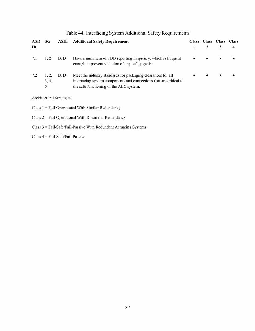
87
Table 44. Interfacing System Additional Safety Requirements ASR ID
SG ASIL Additional Safety Requirement Class 1
Class 2
Class 3
Class 4
7.1 1, 2 B, D Have a minimum of TBD reporting frequency, which is frequent enough to prevent violation of any safety goals.
● ● ● ●
7.2 1, 2, 3, 4, 5
B, D Meet the industry standards for packaging clearances for all interfacing system components and connections that are critical to the safe functioning of the ALC system.
● ● ● ●
Architectural Strategies:
Class 1 = Fail-Operational With Similar Redundancy
Class 2 = Fail-Operational With Dissimilar Redundancy
Class 3 = Fail-Safe/Fail-Passive With Redundant Actuating Systems
Class 4 = Fail-Safe/Fail-Passive

88
10 DIAGNOSTICS AND PROGNOSTICS
10.1 Metrics for Diagnostics
The diagnostics presented in this section are limited to the sensing and evaluation elements of the ALC system and critical interfaces, as described in Section 3.1. While failures in other vehicle systems may be amenable to diagnostic evaluation, this report focuses on methodologies for identifying existing and potential problems within the ALC system and its critical interfaces.
Many diagnostic functions are characterized by detecting when a key parameter strays out of its normal operating range. In any electronic system, short-term anomalies are possible in both the electronic components and the communications network. The safety analysis for a system should identify fault tolerant time intervals over which a fault has to be identified and mitigated. For many serious malfunctions, these FTTIs are significantly less than one second. Therefore continually rechecking abnormal readings is an important part of verifying the diagnostic system integrity. Certain ALC system architectures might also use three-level monitoring, as described in Appendix J.
ISO 26262 provides diagnostic coverage guidelines, including diagnostic coverage levels that correspond to the ASILs of the affected safety goals [6]. Diagnostics coverage levels are associated with the number of failure modes detected by the specific technique. For example, a low diagnostics coverage level for a sensor might only detect out-of-range44 and stuck-in-range45 conditions. A medium diagnostics coverage level for a sensor might also detect offsets, in addition to out-of-range and stuck-in-range conditions. A high diagnostics coverage level might detect oscillations in addition to offsets, out-of-range, and stuck-in-range conditions. Diagnostics coverage supports several metrics required by ISO 26262, including the hardware architectural metrics and the evaluation of safety goal violations due to random hardware failures.
The diagnostic coverage guidelines in ISO 26262 can provide the basis for diagnostic coverage for the ALC system. ISO 26262 specifies how to implement diagnostic coverage for the safety-related functionality of critical ALC system sensors, harnesses, and connectors based on the ASIL of the safety goal that is affected. For example, a diagnostic coverage strategy may include the following elements of the ALC system.
• Main and auxiliary controllers: o Central processing unit o Processor memory o Arithmetic logic unit o Registers o Analog/digital converter
44 The signal is outside the expected range [31]. 45 The signal is in the normal operating range, but is not correct for the current operating conditions [31].

89
o Software program execution o Connections (I/O) faults (short or open circuits) o Power supply
• Critical communication bus messages • Harnesses and connectors (short or open circuits)
10.2 Common Diagnostic Trouble Codes for the ALC System
10.2.1 Assessment of Selected Generic Diagnostic Trouble Codes
DTCs are part of a safety system that senses, diagnoses, and controls situations, using driver warnings when appropriate. DTCs are typically set in response to a detected fault so that relevant information can be retrieved at a later date (e.g., by a repair technician). As part of the system diagnostics, they can also be used to evaluate when and if warnings or instructions should be given to the driver.
SAE Recommended Practice J2012 defines standardized DTCs, including some DTCs relevant to the ALC system. The document uses a five-digit format for DTCs. Powertrain codes always start with the letter P, whereas network codes start with U chassis codes start with C and body system codes start with B. The second digit is numeric -- typically 0, 1, 2, or 3. Predefined SAE (i.e., “controlled” non-OEM-specific) powertrain codes have a 0 or 2 as the second digit. Manufacturer-defined powertrain codes have a 1 or 3 in the second digit. For instance, P0XXX and P2XXX are SAE-controlled powertrain codes while P1XXX and P3XXX are unique to the manufacturer. Predefined SAE network codes, chassis codes, and body system codes have a 0 as the second digit whereas manufacturer-specific network codes, chassis codes, and body system codes have a 1 or 2 as the second digit. Thus, the first two digits can generally be used to determine whether the ALC system DTCs are SAE-controlled codes.
The codes are characterized by the phenomenon they represent. Some DTCs indicate an existing or emerging hazardous state, while others indicate a situation that requires attention to prevent the system from moving toward an unsafe state. System responses to DTCs, such as issuing a driver warning transitioning to a safe state is determined by the manufacturer.
Appendix E0 (Network Systems) of SAE J2012 provides some DTCs specific to the lane detection sensors for the ALC system [31]. However, many of the ALC system related DTCs identified in this study are generic DTCs that broadly apply to electronic components. Review of SAE J2012 identified 12 DTCs that cover ALC system components and interfaces. SAE J2012 also includes 150 DTCs that cover critical ALC system interfaces. Tables 45 and 46 provide a breakdown of these DTCs by the ALC system component or connection, and interfacing system or subsystem. Appendix K summarizes the DTCs relevant to the ALC system.

90
Table 45. Breakdown of Identified DTCs by ALC System Component or Connection ALC System Component or Connection Number of DTCs
ALC Control Module 2 Connective/Online Sensors 4 Lane Detection Sensors 6
Table 46. Breakdown of Identified ALC-Relevant DTCs by Interfacing System or Subsystem
Interfacing System Component or Connection Number of DTCs Active Differential System1 4 Brake Pedal Switch/Position Sensor 5 Brake/Stability Control System1 11 Communication System 72 Cruise Control System (including ACC) 5 Ignition Switch/Start System 8 Instrument Panel Display 7 Power Supply/Battery 5 Rain Sensor2 1 Steering System 3 Steering Wheel Angle Sensor 8 Vehicle Dynamics Sensors 21 1 If used to implement lateral positioning requests from the ALC control module. 2 If used to detect environmental conditions that may be limit operation of the ALC system.
10.2.2 Potential Additional Generic Diagnostic Trouble Code Needs
SAE J2012 does not include DTC coverage of the entire ALC system. Many of the DTCs provided in Appendix L are included in SAE J2012 because of their relevance to the brake/vehicle stability system or other foundational vehicle systems. The DTCs specific to the ALC system are limited to communication-related DTCs, such as lost communication with the image processing module (DTC #U023A) [31].
The ALC system requirements in Section 9 suggest additional DTCs for the ALC system, which could be incorporated into SAE J2012 as part of the generic DTC coverage. These possible DTC coverage areas are listed in Table 47. The DTCs in Table 47 are based on similar DTC types listed in SAE J2012. As indicated in SAE J2012, DTCs for body and chassis systems – such as the ALC system – are typically more general and SAE J2012 does not assign a DTC to each

91
failure mode. Each manufacturer determines the appropriate failure modes to apply to each base DTC description.46
Table 47. Possible Areas for Additional DTC Coverage in the ALC System
Phenomenon Subsystem or Component Lane Detection Sensor (Subfault1) Lane Detection Sensor Connective/Online Sensor (Subfault1) Connective/Online Sensor Driver Awareness Sensor (Subfault1) Driver Awareness Sensor ALC Control Module Programming Error ALC Control Module ALC Control Module Internal Keep Alive Memory (KAM) Error ALC Control Module ALC Control Module Internal Random Access Memory (RAM) Error ALC Control Module ALC Control Module Internal Read Only Memory (ROM) Error ALC Control Module ALC Control Module Processor Error ALC Control Module ALC Control Module Performance ALC Control Module ALC Control Module Vehicle Options Error ALC Control Module ALC Control Module Torque Authority Limit Error ALC Control Module ALC Control Module Torque/Yaw Performance ALC Control Module ALC Control Module Torque/Yaw Calculation Error ALC Control Module ALC Control Module Lane Detection Performance ALC Control Module 1 Manufacturers may elect to provide additional DTC resolution based on specific failure modes for the selected subsystem or component [31].
46 SAE J2012, Section 6.1.

92
11 PERFORMANCE PARAMETERS AND TEST SCENARIOS
11.1 Relationship with Current Regulations
The United Nations Economic Commission for Europe established the Uniform Provisions Concerning the Approval of Vehicles With Regard to Steering Equipment (UNECE R-79) [32]. This standard provides high-level guidance for automatically commanded steering functions47, such as ALC systems. According to UNECE R-79, an ACSF must notify the driver when the system is active. Furthermore, the system is restricted to speeds below 10 kph and must deactivate if the vehicle speed reaches 12 kph [32]. A proposed revision to this standard would provide more detailed guidance for these types of systems for speeds greater than 10 kph [33]. This proposed revision may include metrics that could be considered as possible performance metrics for testing ALC systems.
ALC systems are not currently covered by existing Federal Motor Vehicle Safety Standards.
11.2 Test Scenario Development
This section describes potential test scenarios based on the each of identified vehicle-level hazards and results of the hazard and safety analyses. This section of the report is intended to illustrate how the results of this study may be used to develop a range of possible test scenarios. These test scenarios may be used to verify that the functional safety requirements are achieved. However, these test scenarios should not be interpreted as comprehensive set of test scenarios and additional test scenarios may be necessary to adequately verify the functional safety requirements are achieved.
The test scenarios presented in this section focus on Automation Level 2 (both engaged and not engaged), which are currently in production. The findings from this study could also be used to support development of test scenarios for higher levels of automation. However, additional challenges may exist when testing higher levels of automation [26].
Each test scenario includes the following:
• Test Goals: Each of the safety goals identified in this study serves as the testing goal for a test scenario. The test objective is to ensure that the safety goal is not violated.
• Driving Scenarios: The driving scenario is developed using a combination of the vehicle’s operating scenario and key inputs to the system. Together, this represents the situation under which the system should avoid entering a hazardous state when a fault is injected. The two components of the driving scenario are described below.
o The operating scenarios are generated as part of the ASIL assessment and describe the operating environment of the vehicle. The operating scenarios
47 An ACFS provides continuous control. UNECE R-79 allows for operation of “corrective steering functions” over a wider range of speeds. However, these functions do not provide continuous control (e.g., LKA systems).

93
considered in these test scenarios are based on the variables listed in Table 12. In particular, the ASIL operating scenarios that lead to the highest ASIL value for a hazard may represent worst-case driving situations under which the system should avoid entering a hazardous state. Note that test procedures may deviate from the “worst case” driving situation in the ASIL assessment for the purposes of testing safety. For example, test procedures may be developed that implement lower vehicle speeds if it can be shown that failure modes are independent of speed or if the protocol implements incremental speed increases.
o The context variables used for deriving the UCAs represent key inputs to the system. Certain system behaviors are expected based on the combinations of these context variables to avoid entering a hazardous state.
• Fault Injection: The CFs identified in STPA, and failure modes and faults identified in the functional FMEA may be used as the basis for determining faults to inject at the component and connection levels. Examples of potential faults that could be introduced to the system include inducing hardware failures in system components, transmitting erroneous measurements from sensors, or issuing incorrect controller commands (e.g., to simulate a flaw in the software algorithm).
• Expected Safe Behavior: The test scenarios can be evaluated by monitoring for expected safe behaviors. The following are examples of possible safe behaviors:
o The system may transition into one of the identified safe states within the FTTI. As described in Section 8.3, safe states are operating modes of the system that do not present an unreasonable risk.
o The system’s controller may still be capable of issuing the correct command when a fault is injected. For example, the ALC control module may be capable of using other sensor data to determine the correct amount of steering to command when there’s a disruption in the voltage supply to the yaw rate sensor.
Although the role of the driver was considered in the hazard and safety analyses, the test scenarios presented in this section focus on the behavior of the electronic control system. Evaluation of driver behavior when certain faults are injected into the vehicle would require a human factors study.
11.2.1 Potential Test Scenarios for SG 1
Safety Goal 1 states that the ALC system should prevent insufficient lateral adjustment that results in a lane/roadway departure while the ALC system is engaged. Tables 48 and 49 describe two possible driving scenarios to test this safety goal. Both driving scenarios are based on the same operating scenario, identified as the worst-case scenario from the ASIL assessment, but differ in the level of automation considered:

94
Table 48. Example Driving Scenarios for SG 1 (Driving Scenario #1)
Test Goal Prevent insufficient lateral adjustment that results in a lane/roadway departure while the ALC system is engaged.
Automation Level Level 2 – Driver Engaged
ASIL B
Driving Scenarios
Operating Scenario Driving at medium speeds (100 kph ≥ V > 40 kph) on an undivided collector highway, with pedestrians present.
System Input • The vehicle is offset from the reference trajectory
• Vehicle is oriented toward one of the lane boundaries
• Driving Scenario 1: The vehicle is travelling at medium speeds on an undivided collector highway. The vehicle is offset from the reference trajectory with an orientation that will move the vehicle closer to a lane boundary. This scenario is intended to determine if the vehicle will continue along its current trajectory and ultimately depart the lane/roadway following an induced fault.
Table 49. Example Driving Scenarios for SG 1 (Driving Scenario #2)
Test Goal Prevent insufficient lateral adjustment that results in a lane/roadway departure while the ALC system is engaged.
Automation Level Level 2 – Driver Not Engaged
ASIL D
Driving Scenarios
Operating Scenario Driving at medium speeds (100 kph ≥ V > 40 kph) on an undivided collector highway, with pedestrians present.
System Input
• The vehicle is offset from the reference trajectory
• Vehicle is oriented toward one of the lane boundaries
• The driver is not engaged in the driving task
• Driving Scenario 2: This scenario is similar to Driving Scenario 1. However, in Driving Scenario 2, the driver is not engaged in the driving task. This scenario is intended to

95
determine if an induced fault may cause the vehicle to depart the lane/roadway before the driver can resume control of the vehicle.
For each of the two test scenarios listed in Tables 48 and 49, potential faults could be simulated in the ALC system to determine if these faults result in violation of the safety goal. The induced faults presented in Tables 50 and 51 are examples of potential faults that can be derived from the STPA and functional FMEA results. The lists of potential faults in Tables 50 and 51 are not intended to be exhaustive. The full STPA and functional FMEA results in Appendix H and Appendix I can be used to identify additional faults to include in the test scenarios.

96
Table 50. Examples of Simulated Faults to Test SG 1 Under Driving Scenario 1
Test Goal Prevent insufficient lateral adjustment that results in a lane/roadway departure while the ALC system is engaged.
Automation Level Level 2 - Engaged
ASIL B
Driving Scenarios
Operating Scenario Driving at medium speeds (100 kph ≥ V > 40 kph) on an undivided collector highway, with pedestrians present.
System Input • The vehicle is offset from the reference trajectory
• Vehicle is oriented toward one of the lane boundaries
Injected Fault (Examples)
ALC Control Module
• Subject the ALC control module to a range of EMI and ESD disturbances. (CF #3, 15)
• Disrupt the power supply to the ALC control module. (CF #13, 14) • Issue a request to the foundational systems for less torque/yaw than
required to bring the vehicle to the reference trajectory (i.e., simulate a software fault). (CF #28, 302, 306, 307, 311)
Lane Detection Sensor
• Simulate internal shorts in one of the lane detection sensors (to ground, battery, etc.). (CF #77, 78)
• Subject the lane detection sensor to extreme environmental temperatures (e.g., < -20°F or > 130°F). (CF #79, 88)
Incoming Connection from Steering Wheel Angle Sensor
• Simulate a short in the connection to the ALC control module. (CF #372, 375)
• Subject the connection between the steering wheel angle sensor and ALC control module to a range of EMI disturbances. (CF #131, 142)
Outgoing Connection to Steering System
• Simulate an intermittent signal connection from the ALC control module to the steering system. (CF #946)
• Initiate a range of communication bus faults on the communication bus connecting the ALC control module with the steering system control module. (CF #954, 955, 956, 957)
• Place the steering system in a degraded operating mode that cannot respond to ALC requests. (CF #1108)
Expected Safety Strategies • Detects the fault and keeps the vehicle within the travel lane. • Transitions to the appropriate safe state based on the fault.

97
Table 51. Examples of Simulated Faults to Test SG 1 Under Driving Scenario 2
Test Goal Prevent insufficient lateral adjustment that results in a lane/roadway departure while the ALC system is engaged.
Automation Level Level 2 – Not Engaged
ASIL D
Driving Scenarios
Operating Scenario Driving at medium speeds (100 kph ≥ V > 40 kph) on an undivided collector highway, with pedestrians present.
System Input
• The vehicle is offset from the reference trajectory
• Vehicle is oriented toward one of the lane boundaries
• The driver is not engaged in the driving task
Injected Fault (Examples)
ALC Control Module
• Subject the ALC control module to a range of EMI and ESD disturbances. (CF #3, 15)
• Disrupt the power supply to the ALC control module. (CF #13, 14) • Issue a request to the foundational systems for less torque/yaw than
required to bring the vehicle to the reference trajectory (i.e., simulate a software fault). (CF #28, 302, 306, 307, 311)
Lane Detection Sensor
• Simulate internal shorts in one of the lane detection sensors (to ground, battery, etc.). (CF #77, 78)
• Subject the lane detection sensor to extreme environmental temperatures (e.g., < -20°F or > 130°F). (CF #79, 88)
Incoming Connection from Steering Wheel Angle Sensor
• Simulate a short in the connection to the ALC control module. (CF #372, 375)
• Subject the connection between the steering wheel angle sensor and ALC control module to a range of EMI disturbances. (CF #131, 142)
Outgoing Connection to Steering System
• Simulate an intermittent signal connection from the ALC control module to the steering system. (CF #946)
• Initiate a range of communication bus faults on the communication bus connecting the ALC control module with the steering system control module. (CF #954, 955, 956, 957)
• Place the steering system in a degraded operating mode that cannot respond to ALC requests. (CF #1108)
Expected Safety Strategies • Detects the fault and keeps the vehicle within the travel lane. • Transitions to the appropriate safe state based on the fault.

98
Tables 50 and 51 illustrate that the same set of injected faults could potentially be used to evaluate driving scenarios for different levels of automation. Aside from slight differences in the driving scenario, the key difference between Table 50 and Table 51 is the expected safety strategy. In Table 50, which evaluates a Level 2 automated system where the driver is engaged, the expected safety strategy may include immediately reverting to manual control. However, in Table 51, which evaluates a Level 2 automated system where the driver is not engaged, the expected safety strategy may instead include continued operation for TBD48 seconds before reverting to manual control.
11.2.2 Potential Test Scenarios for SG 2
Safety Goal 2 states that the ALC system prevent excessive lateral adjustment that results in a lane/roadway departure while the ALC system is engaged. Table 52 describes one possible driving scenarios to test this safety goal.
Table 52. Example Driving Scenarios for SG 2
Test Goal Prevent excessive lateral adjustment that results in a lane/roadway departure while the ALC system is engaged.
ASIL D
Automation Level Level 2 – Engaged1
Driving Scenarios
Operating Scenario Driving at medium speeds (100 kph ≥ V > 40 kph) on an undivided collector highway, with pedestrians present.
System Input • The vehicle is following the reference trajectory
• The driver is not maneuvering the vehicle
1 A similar driving scenario could be used to test the “Level 2 – Not Engaged” case, as described in Section 11.2.1.
• Driving Scenario 1: The vehicle is following the reference trajectory at a medium speed on an undivided collector highway. This scenario is intended to determine if an induced fault may cause the ALC system to steer the vehicle out of the lane/roadway.
48 The duration for transitioning control to the driver may vary based, in part, on the specific system design (e.g., the types of driver alerts or level of driver awareness monitoring).

99
For the test scenario listed in Table 52, potential faults could be simulated in the ALC system to determine if these faults result in violation of the safety goal. The induced faults presented in Table 53 are examples of potential faults that can be derived from the STPA and functional FMEA results. The lists of potential faults in Table 53 are not intended to be exhaustive. The full STPA and functional FMEA results in Appendix H and Appendix I can be used to identify additional faults to include in the test scenarios.

100
Table 53. Examples of Simulated Faults to Test SG 2 Under Driving Scenario 1
Test Goal Prevent excessive lateral adjustment that results in a lane/roadway departure while the ALC system is engaged.
ASIL D
Automation Level Level 2 – Engaged1
Driving Scenarios
Operating Scenario Driving at medium speeds (100 kph ≥ V > 40 kph) on an undivided collector highway, with pedestrians present.
System Input • The vehicle is following the reference trajectory
• The driver is not maneuvering the vehicle
Injected Fault (Examples)
ALC Control Module
• Subject the ALC control module to a range of EMI and ESD disturbances. (CF #3, 15)
• Issue a torque command to the foundational steering system (i.e., simulate a software fault). (CF #28, 31, 302, 306, 312)
• Corrupt the stored calibration maps in the ALC control module. (CF #30, 32)
Lane Detection Sensor
• Disrupt the power supply to the lane detection sensors. (CF #93, 94) • Subject the lane detection sensors to a range of EMI disturbances. (CF
#85, 95) • Transpose the lane detection sensor signals for the left and right
lane/roadway markings. (CF #532)
Yaw Rate/Lateral Acceleration Sensor
• Transmit an incorrect yaw rate or lateral acceleration value to the ALC control module. (CF #223, 225, 307, 311)
Outgoing Connection to Steering System
• Initiate a range of communication bus faults on the communication bus connecting the ALC control module with the steering system control module. (CF #954, 955, 956, 957)
Expected Safety Strategies • Detects the fault and keeps the vehicle within the travel lane. • Transitions to the appropriate safe state based on the fault.
1 A similar driving scenario and set of injected faults could be used to test the “Level 2 – Not Engaged” case, as described in Section 11.2.1. The expected safety strategies would need to be adjusted accordingly.

101
11.2.3 Potential Test Scenarios for SG 3
Safety Goal 3 states that the ALC system prevent unexpected loss of the ALC system. As described in Section 4.1, this hazard specifically covers situations where the ALC system disengages without prior warning to the driver. This study derives one possible driving scenario to test this safety goal, shown in Table 54.
Table 54. Example Driving Scenario for SG 3
Test Goal Prevent unexpected loss of the ALC system.
ASIL D
Automation Level Level 2 – Not Engaged
Driving Scenarios
Operating Scenario Driving at medium speeds (100 kph ≥ V > 40 kph) on an undivided collector highway, with pedestrians present.
System Input
• The vehicle is offset from the reference trajectory
• Vehicle is oriented toward one of the lane boundaries
• The driver is not engaged in the driving task
• Driving Scenario 1: The vehicle is travelling at medium speeds on an undivided collector highway. The vehicle is offset from the reference trajectory with an orientation that will move the vehicle closer to a lane boundary. The driver is not engaged in the driving task (texting, reading, etc.). This scenario is intended to determine if an induced fault could cause the ALC system to disengage without providing the driver with sufficient notification to regain control of the vehicle.
The induced faults presented in Table 55 are examples of potential faults that can be derived from the STPA and functional FMEA results. The lists of potential faults in Table 55 are not intended to be exhaustive. The full STPA and functional FMEA results in Appendix H and Appendix I can be used to identify additional faults to include in the test scenario.

102
Table 55. Examples of Simulated Faults to Test SG 3 Under Driving Scenario 1
Test Goal Prevent unexpected loss of the ALC system.
ASIL D
Automation Level Level 2 – Not Engaged
Driving Scenarios
Operating Scenario Driving at medium speeds (100 kph ≥ V > 40 kph) on an undivided collector highway, with pedestrians present.
System Input
• The vehicle is offset from the reference trajectory
• Vehicle is oriented toward one of the lane boundaries
• The driver is not engaged in the driving task
Injected Fault (Examples)
ALC Control Module
• Simulate simultaneous primary and secondary control inputs to the ALC control module (e.g., a request to engage the system coincident with activation of the turn signal). (CF #1107)
• Disrupt the power supply to the ALC control module. (CF #13, 14) • Simulate an internal short circuit in the ALC control module. (CF #20,
23)
Primary/Secondary Controls
• Simulate a short or open circuit in a primary or secondary control that disengages the ALC system. (CF #559, 561, 582, 584, 604, 606, 627, 629)
Incoming Connection From Other Vehicle Systems
• Simulate a “suspend” or “disengage” command from another vehicle system to the ALC control module (e.g., ESC or automatic lane change). (CF #1, 2)
Expected Safety Strategies • Detects the fault and the ALC system remains operational. • Transitions to the appropriate safe state based on the fault.
11.2.4 Potential Test Scenarios for SG 4
Safety Goal 4 states that the ALC system ensure proper transition of control between the driver and the ALC system under all vehicle operating conditions. This study derived two possible driving scenarios to test this safety goal, which are shown in Tables 56 and 57.

103
Table 56. Example Driving Scenario for SG 4 (Driving Scenario #1)
Test Goal Ensure proper transition of control between the driver and the ALC system under all vehicle operating conditions.
ASIL B
Automation Level Level 2 – Engaged
Driving Scenarios
Operating Scenario Driving at medium speeds (100 kph ≥ V > 40 kph) on an undivided collector highway, with pedestrians present.
System Input • The driver is attempting to disengage the ALC system.
• Driving Scenario 1: The vehicle is travelling at medium speeds on an undivided collector highway. The driver is attempting to disengage the ALC system either through primary or secondary controls. This scenario is intended to determine if an induced fault may affect the ability of the ALC system to relinquish control back to the driver.
Table 57. Example Driving Scenario for SG 4 (Driving Scenario #2)
Test Goal Ensure proper transition of control between the driver and the ALC system under all vehicle operating conditions.
ASIL D
Automation Level Level 2 – Not Engaged
Driving Scenarios
Operating Scenario Driving at medium speeds (100 kph ≥ V > 40 kph) on an undivided collector highway, with pedestrians present.
System Input • The driver is not engaged in the driving task.
• Driving Scenario 2: The vehicle is travelling at medium speeds on an undivided collector highway. The driver is not engaged in the driving task. This scenario is intended to determine if the ALC system could potentially transfer control back to the driver when the driver is unable to steer the vehicle.
The induced faults presented in Tables 58 and 59 are examples of potential faults that can be derived from the STPA and functional FMEA results. The lists of potential faults in Tables 58 and 59 are not intended to be exhaustive. The full STPA and functional FMEA results in

104
Appendix H and Appendix I can be used to identify additional faults to include in the test scenarios.
Table 58. Examples of Simulated Faults to Test SG 4 Under Driving Scenario 1
Test Goal Ensure proper transition of control between the driver and the ALC system under all vehicle operating conditions.
ASIL B
Automation Level Level 2 – Engaged
Driving Scenarios
Operating Scenario Driving at medium speeds (100 kph ≥ V > 40 kph) on an undivided collector highway, with pedestrians present.
System Input • The driver is attempting to disengage the ALC system.
Injected Fault (Examples)
ALC Control Module
• Simulate simultaneous primary and secondary control inputs to the ALC control module (e.g., a request to disengage the system coincident with cancelling the turn signal). (CF #1107)
• Simulate a memory fault while writing the current operating mode to memory. (CF #25, 1154)
• Simulate an internal short circuit in the ALC control module. (CF #20, 23)
Primary or Secondary Control
• Simulate a short or open circuit in a primary or secondary control that disengages the ALC system. (CF #559, 561, 582, 584, 604, 606, 627, 629)
• Subject the primary or secondary control to a range of EMI disturbances. (CF #566, 574, 588, 598, 611, 619, 634, 643)
Incoming Connection from Steering Wheel Angle Sensor
• Simulate an intermittent or open circuit in the connection between the steering wheel angle sensor and ALC control module. (CF #371, 372)
• Initiate a range of communication bus faults on the communication bus connecting the steering wheel angle sensor and ALC control module. (CF #954, 955, 956, 957)
Expected Safety Strategies • Detects the fault and relinquishes lateral control of the vehicle to the
driver. • Transitions to the appropriate safe state based on the fault.

105
Table 59. Examples of Simulated Faults to Test SG 4 Under Driving Scenario 2
Test Goal Ensure proper transition of control between the driver and the ALC system under all vehicle operating conditions.
ASIL D
Automation Level Level 2 – Not Engaged
Driving Scenarios
Operating Scenario Driving at medium speeds (100 kph ≥ V > 40 kph) on an undivided collector highway, with pedestrians present.
System Input • The driver is not engaged in the driving task.
Injected Fault (Examples)
ALC Control Module
• Disrupt the power supply to the ALC control module. (CF #13, 14) • Simulate an internal short circuit in the ALC control module. (CF #20,
23)
Driver Awareness Sensors
• Reduce the reporting frequency or communication bus signal priority for the driver awareness sensors. (CF #539, 713)
• Subject the driver awareness sensor to extreme environmental temperatures (e.g., < -20°F or > 130°F). (CF #536, 546, 553)
Outgoing Connection from ALC Control Module to Instrument Panel Display
• Delay the signal from the ALC control module to the instrument panel display (e.g., countdown before system disengages). (CF #1034, 1111)
• Subject the connection from the ALC control module to the instrument panel display to a range of EMI disturbances. (CF #1035, 1043)
• Simulate an open circuit in the connection from the ALC control module to the instrument panel display. (CF #1115)
Expected Safety Strategies • Detects the fault and does not terminate control until the driver is re-
engaged in the driving task • Transitions to the appropriate safe state based on the fault.
11.2.5 Potential Test Scenarios for SG 5
Safety Goal 5 states that the ALC system ensure coordination of lateral control actions with other vehicle systems or functions. This study derived one possible driving scenario to test this safety goal, which is shown in Table 60.

106
Table 60. Example Driving Scenario for SG 5
Test Goal Ensure coordination of lateral control actions with other vehicle systems or functions.
ASIL D
Automation Level Level 2 – Not Engaged
Driving Scenarios
Operating Scenario Driving at medium speeds (100 kph ≥ V > 40 kph) on an undivided collector highway, with pedestrians present.
System Input
• The vehicle is offset from the reference trajectory
• Vehicle is oriented toward one of the lane boundaries
• Another vehicle system requests the ALC system to suspend operation.
• Driving Scenario 1: The vehicle is travelling at medium speeds on an undivided collector highway and another vehicle system issues a request to suspend operation of the ALC system. The driver is not engaged in the driving task, limiting their ability to support the other vehicle system (e.g., disengaging the ALC system). This scenario is intended to determine if the ALC system could potentially interfere with the operation of other vehicle systems, such as ESC or a pedestrian avoidance steer assist system.
The induced faults presented in Table 61 are examples of potential faults that can be derived from the STPA and functional FMEA results. The lists of potential faults in Table 61 are not intended to be exhaustive. The full STPA and functional FMEA results in Appendix H and Appendix I can be used to identify additional faults to include in test scenarios.

107
Table 61. Examples of Simulated Faults to Test SG 5 Under Driving Scenario 1
Test Goal Prevent insufficient and loss of braking under all vehicle operating conditions.
ASIL D
Automation Level Level 2 – Not Engaged
Driving Scenarios
Operating Scenario Driving at medium speeds (100 kph ≥ V > 40 kph) on an undivided collector highway, with pedestrians present.
System Input
• The vehicle is offset from the reference trajectory
• Vehicle is oriented toward one of the lane boundaries
• Another vehicle system requests the ALC system to suspend operation.
Injected Fault (Examples)
ALC Control Module
• Subject the ALC control module to a range of EMI and ESD disturbances. (CF #3, 15)
• Issue a torque command to the foundational steering system (i.e., simulate a software fault). (CF #524, 808, 809)
Incoming Connection From Other Vehicle Systems
• Simulate a corrupted signal to the ALC control module (shorts, EMI disturbances, etc.). (CF #1, 2)
• Broadcast the request to suspend ALC operation with the incorrect priority. (CF #808)
Expected Safety Strategies • Detects the fault and appropriately responds to other vehicle systems. • Transition to the appropriate safe state based on the fault.

108
12 CONCLUSIONS
This study followed the Concept Phase process (Part 3) in ISO 26262 standard to derive a list of potential safety goals and functional safety requirements for the ALC system. Specifically, this research:
1. Identified five vehicle-level safety goals and assessed their ASILs:
ID Safety Goals
ASIL
Level 1
Level 2 Engaged
Level 2 Not
Engaged1
Level 3
Level 4
Level 5
SG 1 Prevent insufficient lateral adjustment that results in a lane/roadway departure while the ALC system is engaged in accordance with the identified ASIL.
B B D D D D
SG 2 Prevent excessive lateral adjustment that results in a lane/roadway departure while the ALC system is engaged in accordance with the identified ASIL.
D D D D D D
SG 3 Prevent unexpected loss of the ALC system in accordance with the identified ASIL. B B D D D D
SG 4 Ensure proper transition of control between the driver and the ALC system in accordance with the identified ASIL.
B B D D D2 D2
SG 5 Ensure coordination of lateral control actions with other vehicle systems or functions in accordance with the identified ASIL.
B B D D D D
1 Based on the assumption of foreseeable driver misuse that prevents the driver from immediately resuming control of the vehicle in the event of a failure. 2 This ASIL only applies if the human operator is able to resume control of the vehicle.
2. Developed the functional safety concept and identified 47 functional safety requirements and 26 additional safety requirements by following the Concept Phase in the ISO 26262 standard, combining the results of the two safety analyses (functional FMEA and STPA), and leveraging industry practice experiences. The breakdown of the number of requirements is as follows. • General ALC System – 13 requirements • ALC Control Module – 34 requirements • Lane Detection Sensors – 4 requirements • Driver Awareness Sensors – 3 requirements • Primary and Secondary Driver Controls – 5 requirements • Power Supply – 1 requirement • Communication Systems – 3 requirements • Interfacing Systems – 10 requirements

109
3. Identified 12 generic DTCs included in SAE J2012 that provide coverage of the ALC
system and 150 DTCs that provide coverage for safety-critical interfacing components and systems. In addition, this study identified 14 potential DTCs that could provide additional coverage of the ALC system.
4. Developed seven example test scenarios which could be used to validate the safety goals and functional safety requirements. The results from this study could also be used to develop a more comprehensive set of test scenarios.

110
REFERENCES
[1] National Highway Traffic Safety Administration. (2017, September). Automated driving systems 2.0: A vision for safety (Report No. DOT HS 812 442 ).Washington, DC: Author. Available at www.nhtsa.gov/sites/nhtsa.dot.gov/files/documents/13069a-ads2.0_090617_v9a_tag.pdf
[2] SAE International. (2014). Taxonomy and Definitions for Terms Related to On-Road Motor Vehicle Automated Driving Systems (SAE J3016). Warrendale, PA: SAE International.
[3] Stanyer, T., & Chutorash, R. (2014, October 27). Interviewees, ESG Automotive Subject Matter Expert Interview on Automated Lane Centering. [Interview].
[4] Lee, J.-W., Moshchuk, N. K., & Chen, S.-K. (2014, March 11). Lane Centering Fail-Safe Control Using Differential Braking. U.S. Patent No. 8,670,903.. Washington, DC: U.S. Patent Trademark Office..”
[5] Kade, A., Bartz, D., Hudas, G., & D. G. Mikulski, D. G. (2014, October 28). Tank Automotive Research, Development and Engineering Center Subject Matter Expert Interview on Automated Lane Centering. [Interview].
[6] International Organization for Standardization. (2011). Road vehicles - functional safety( Final Draft). (ISO 26262). Geneva: Author.
[7] International Electrotechnical Commission. (2001). Hazard and operability studies (HAZOP Studies) - Application guide, Edition 1.0. (IEC 61882-2001). Geneva: Author.
[8] Leveson, N. (2012). Engineering a safer world. Cambridge, MA:: MIT Press.
[9] Society of Automotive Engineers. (1994). Potential failure mode and effects analysis in design and potential failure mode and effects analysis in manufacturing and assembly processes. (SAE J1739). Warrendale, PA: Author. [Editor’s note: In 2006 the Society of Automotive Engineers changed its name to SAE International.]
[10] Thomas, J. (2013). Extending and Automating a Systems-Theoretic Hazard Analysis for Requirements Generation and Analysis (Ph.D. dissertation). Cambridge, MA: Massachusetts Institute of Technology.

111
[11] Coudert, O. (1994). Two-level logic minimization: An overview, Integration, the VLSI Journal, 17(2), pp. 97-140.
[12] ZF TRW. (2016). Lateral Support (LDW / LKA / LCA). Retrieved from http://www.trw.com/integrated_systems/driver_assist_systems/lateral_support
[13] Daimler AG. (2016). Mercedes-Benz TechCenter: DISTRONIC PLUS with Steering Assist. Retrieved from https://techcenter.mercedes-benz.com/en/distronic_plus_steering_assist/detail.html
[14] Donath, M., & Creaser, J. (2014, October 15). Interviewees, University of Minnesota Subject Matter Expert Interview on Automated Lane Centering. [Interview].
[15] Miller, J., Seewald, A., Heitzer, H.-D., Wegner, M., Kristofik, J., & Standtke, P. (2014, October 29). Interviewees, TRW Automotive Subject Matter Expert Interview on Automated Lane Centering. [Interview].
[16] Urmson, C., & Darrickson, J. (2014, October 30). Interviewees, Google, Inc. Subject Matter Expert Interview on Automated Lane Centering. [Interview].
[17] Zhang, W. B. (2014, October 16). Interviewee, University of California, Berkeley, Subject Matter Expert Interview on Automated Lane Centering. [Interview].
[18] Mercedes-Benz. (2016). C-Class Operator's Manual, B ed. (Part No. 205 584 15 05 ).Stuttgart, Germany: Author. Available at www.mbusa.com/vcm/-MB/DigitalAssets/pdfmb/ownersmanual/MY16_C_Sedan.pdf
[19] Mosher, A. (2016, July 1). Tesla drivers play Jenga, sleep, using Autopilot in nerve-wracking videos. McLean, VA: USA Today. Retrieved from www.usatoday.com/story/tech/news/2016/07/01/drivers-play-jenga-sleep- using-tesla-autopilot-nerve-wracking-videos/86613484/
[20] Krok, A. (2015, November 11). This is the stupidest misuse of Tesla's Autopilot yet, CNET: Road/Show.. Retrieved from www.cnet.com/roadshow/news/this- is-the-stupidest-misuse-of-teslas-autopilot-yet/
[21] Adams, E. Mercedes's New E-Class Kinda Drives Itself - and It's Kinda Confusing, Wired.com, 27 June 2016. [Online]. Available: www.wired.com/2016/06/ mercedess-new-e-class-kinda-drives-kinda-confusing/
[22] State Farm. (2016, August 31). Self-Driving Cars: What to Do With All That Spare Time, State Farm Mutual Automobile Insurance Company. Bloomington, IL:

112
Author. Available at https://newsroom.statefarm.com/state-farm-releases-autonomous-vehicles-survey-results?cmpid=PArel083116autonomousvehicles&utm_source=Direct
[23] Lemer, N., Jenness, J., Robinson, E., Brown, T., Baldwin, C., & Llaneras, R. (2011). Crash Warning Interface Metrics. (Report No. DOT HS 811 470a). Washington, D: National Highway Traffic Safety Administration Available at https://www.nhtsa.gov/sites/nhtsa.dot.gov/files/811470a.pdf
[24] Merat, N., Jamson, A. H., Lai, F. C., Daly, M., & Carsten, O. M. Transition to Manual: Driver Behavior when Resuming Control from a Highly Automated Vehicle, Elsevier: Transportation Research, vol. Part F, no. 27, pp. 274-282, 2014.
[25] Box, T. (2016, August 17). No Steering Wheel or Pedals in Ford's Plan for Fully Autonomous Car by 2021 Dallas: Dallas Morning News. Retrieved from www.dallasnews.com/business/autos-latest-news/20160817-no-steering- wheel-or-pedals-in-ford-s-plan-for-fully-autonomous-car-by-2021.ece
[26] Koopman, P., & Wagner, M. (2016). Challenges in Autonomous Vehicle Testing and Validation. Detroit: SAE World Congress.
[27] International Electrotechnical Commission. (2016). Functional Safety - IEC 61508 Explained ( IEC 61508) Geneva: Author.Available at www.iec.ch/functionalsafety/explained/
[28] Isermann, R., Schwarz, R., & Stölzl, S. (2002, October). Fault-Tolerant Drive-by-Wire Systems, IEEE Control Systems. Piscataway, NJ: Institute of Electrical and Electronics Engineers.
[29] Lee, J.-W., Moshchuk, N. K., & Chen, S.-K. (2014, March 11). Lane Centering Fail-Safe Control Using Differential Braking. U.S. Patent No. 8,670,903.. Washington, DC: U.S. Patent Trademark Office..”
[30] Department of Defense. (2012). Department of Defense Standard Practice: System Safety (MIT-STD-882E). Washington, DC: Author.
[31] Society of Automotive Engineers. (2007). Diagnostic Trouble Code Definitions (SAE J2012) Warrendale, PA: Author.[Editor’s note: In 2006 the Society of Automotive Engineers changed its name to SAE International.]

113
[32] United Nations Economic Commission for Europe. (1988, December 1). RegulationNo. 79: Uniform Provisions Concerning the Approval of Vehicles with Regard to Steering Equipment (Multilateral Treaty, Chapter XI, Transport and Communications, [Section] B. Road Traffic). Available at https://treaties.un.org/Pages/ViewDetails.aspx?src=TREATY&mtdsg_no=XI-B-16-79&chapter=11&clang=_en
[33] United Nations Economic Commission for Europe. (2016, January 15). Proposal forAmendments to Regulation No. 79 to Include ACSF > 10 km/h (Informal Document No. ACSF-02-03) Available at www2.unece.org/wiki/download/attachments/27459841/ACSF-04-20%20%20%28Secretary%29%20Consolidated%20Document%20after%204th%20session.pdf?api=v2 [See United Nations Economic Commission for Europe, 1988, Reference [32] above.]
[34] SAE International.. (2015) Considerations for ISO 26262 ASIL Hazard Classification(SAE J2980) Warrendale, PA: Author.
[35] Tesla Motors. (2016). Model S Owner's Manual. Palo Alto, CA: Author.
[36] Kammel, S., & Pitzer, B. (2008). Lidar-based Lane Marker Detection and Mapping. InIEEE Intelligent Vehicles Symposium, Eindhoven, The Netherlands, June 4-6, 2008.

DOT HS 812 573 August 2018
13498a-080318-v3