Embed Size (px)
Citation preview

FUNCTIONAL REQUIREMENTS
Techn
ical Man
ual V
11
- TS-0
11
-11
.00
-18
08
14
FU
NC
TIO
NA
L RE
QU
IRE
ME
NT
S
135
Workmanship
i. All workmanship must be within the tolerances defined in Chapter 1 of this Manual.ii. All work is to be carried out by a technically competent person in a
workmanlike manner.iii. Certification is required for any work completed by an approved
installer.
Materials
i. All materials should be stored correctly in a manner that will not cause damage or deterioration of the product. Timber frame elements should be appropriately covered to keep components dry.
ii. All materials, products and building systems shall be appropriate and suitable for their intended purpose.
iii. The structure shall, unless specifically agreed otherwise with the Warranty provider, have a life of not less than 60 years. Individual components and assemblies, not integral to the structure, may have a lesser durability, but not in any circumstances less than 15 years.
Design
i. The design and specifications shall provide a clear indication of the design intent and demonstrate a satisfactory level of performance, supported by structural calculations provided by a suitably qualified expert.
ii. The materials, design and construction must meet the relevant Building Regulations, British Standards, Eurocodes and other statutory requirements.
iii. Any off-site manufactured engineered beams/posts must have structural calculations endorsed by the manufacturer.
7.3 TIMBER FRAME
Chapter 7

Techn
ical Man
ual V
11
- TS-0
11
-11
.00
-18
08
14
CHAPTER 7: SuperstructureCH
AP
TE
R 7
: SUP
ER
STR
UC
TU
RE
7.3.1 Specifications
7.3.1.1 Introduction
This Chapter refers to ‘conventional’ timber frame ‘open panel’ systems made ‘off-site’ under factory conditions. Such panel systems are required to be designed, manufactured and erected on-site under quality assured systems and be either Structural timber Association or TRADA BM registered.
Timber frame external walls are generally considered to consist of load-bearing solid timber studs at regular centres with insulation between them, lined with a structural sheathing board, breather membrane, drained cavity and cladding. A Vapour Control Layer (VCL) and fire-resistant linings are provided to the internal finishes. For guidance on other forms of timber construction, e.g. SIPs, I section studs, Glulam, etc., please refer to Chapter 3 – Modern Methods of Construction, in this Manual.
Figure 1: Typical timber frame external wall
Techn
ical Man
ual V
11
- TS-0
11
-11
.00
-18
08
14
CHAPTER 7: SuperstructureCH
AP
TE
R 7
: SUP
ER
STR
UC
TU
RE
Chapter 7
137
7.3.1.2 General specifications
Note: Bespoke timber frame open panel systems that do not have such QA procedures as the ‘conventional’ timber frame open panel systems described in Chapter 7.3.1.1 will need either third-party accreditation or independent Structural Engineer supervision and monitoring of the installation, erection and completion (sign off) of the system. All load-bearing timbers will have to be treated in accordance with BS 8417 and according to their position within the frame, and evidence of the treatment carried out will be asked for.
Green Oak is not acceptable for use in external wall (and gables) constructions where it is exposed to the elements. Where not exposed (i.e. a continuous weather proof cladding protects the frame), the structural engineer must provide suitable details of the anticipated movement/shrinkage that will occur over the warranty period, and how the external cladding will accommodate that movement without putting the weather proof cladding at risk of allowing water penetration to occur.
Structurally Insulated Panels (SIPs) are a form of composite panel. Only systems with independent third-party approval will meet the requirements of the Technical Manual; please refer to Chapter 3.
7.3.1.3 Structural design
Wind, roof and floor loads should be considered in the design. All timber frame structures shall be designed in accordance with Eurocode 5. Structures designed in accordance with BS 5268 may still be acceptable, although these standards have now been superseded by Eurocode 5. When published, PD 6693: Complementary information for use with Eurocode 5 (currently in draft with BSI) will reference complementary, non-contradictory information found in BS 5268.
Quality assurance
All Timber Frame Designers, Manufacturers and Erectors should possess current certification from at least one of the following quality assurance schemes:
• BM TRADA QMark for timber frame• ISO 9001• CE Marking
7.3.1.4 Timber specifications
Grading of structural timber
All structural timber, whether machine or visually graded, shall be graded in accordance with BS EN 14081: Timber structures – Strength graded structural timber with rectangular cross section.
All load-bearing solid timber studs, rails, binders and sole plates should be of a minimum dry graded C16.
Figure 2: Typical grading stamp
Sizing of structural timber
Timber studs and rails shall be a minimum of 37mm in width.
Treatment of structural timber
All load-bearing timber components shall be either naturally durable or treated in accordance with BS 8417: Preservation of wood. Code of Practice. Sole plates and load-bearing timber studwork are considered to be in ‘Use Class 2’. Sole plates are normally considered to be included in ‘Service Factor Code C’, while load-bearing timber studwork is included in ‘Service Factor Code B’.
All structural timber should be treated with a preservative suitable for the ‘Use Class’ and ‘Service Factor’ applicable to its use.
Where treated timber is cut, the exposed end will not be protected by the original preservative treatment. When treated, timbers are cut in the factory or on-site; the cut ends shall be pre-treated with a preservative compatible with the original treatment used.

Techn
ical Man
ual V
11
- TS-0
11
-11
.00
-18
08
14
CHAPTER 7: SuperstructureCH
AP
TE
R 7
: SUP
ER
STR
UC
TU
RE
Sheathing boards
Sheathing boards are fixed to the timber frame in order to provide racking resistance to the structure.
Structural sheathing board materials may be any of the following:
• Orientated Strand Board (OSB)• Plywood• Impregnated soft board• Medium board• Tempered hardboard• Other board material with suitable third-party
certification for primary racking resistance
All wood-based panel products should comply with BS EN 13986: Wood-based panels for use in construction – Characteristics, evaluation of conformity and marking.
OSB should be grade 3 or 4 in accordance with BS EN 300: Oriented Strand Boards (OSB) –Definitions, classification and specifications.
Plywood should be Class 3 Structural in accordance with BS EN 636: Plywood Specifications.
Impregnated soft boards should be Type SB.HLS in accordance with BS EN 622-4: Fibreboards. Specifications. Requirements for soft boards.
Sole plates
Sole plates are the first structural timber component installed on-site. Its purpose is to set out the building, transfer loads to the foundations and provide a level base for erecting the wall panels. All structural timber should be located
at least 150mm above finished external ground level, except for localised ramping (incorporating satisfactory drainage and ventilation detailing) around door openings.
Sole plates should be fixed to the foundations with shot fired nails. Proprietary sole plate fixings, anchors, brackets or straps may be used, subject to suitable third-party certification or as specified by a Structural Engineer.
Figure 3: Sole plate/foundation junctions

Techn
ical Man
ual V
11
- TS-0
11
-11
.00
-18
08
14
CHAPTER 7: SuperstructureCH
AP
TE
R 7
: SUP
ER
STR
UC
TU
RE
Chapter 7
139
Medium board should be type MBH.HLS1 or MBH.HLS2 in accordance with BS EN 622-3: Fibreboards. Specifications. Requirements for medium boards.
Tempered hardboards should be Type HB.HLA1 or HB.HLA2 in accordance with BS EN 622-2: Fibreboards. Specifications. Requirements for hardboards.
7.3.1.5 Other material specifications
Fixings
All sole plate fixings and holding down products should be austenitic stainless steel.
Timber components and structural sheathing boards may be fixed with:
• Nails• Staples
Nail fixings should be:
• Austenitic stainless steel• Galvanised• Sheradised
Staple fixings should be austenitic stainless steel or similar.
Breather membrane
A breather membrane is a water-resistant, moisture vapour permeable membrane used to provide temporary weather protection during
construction, and secondary protection from moisture once the building is complete.The timber frame structure should always be protected by a breather membrane.
Breather membranes should be:
• A Type 1 membrane in accordance with BS 4016: Specifications for flexible building membranes (breather type).
• Self-extinguishing.• Securely fixed to protect the outside face
of the timber frame structure with austenitic stainless steel staples.
Cavity barriers
Cavity barriers are required to prevent the spread of smoke and flame within concealed spaces.
Cavity barriers may be constructed from:
• Steel at least 0.5mm thick• Timber at least 38mm thick• Polythene sleeved mineral wool• Mineral wool slab• Calcium silicate, cement-based or gypsum-based board at least 12mm thick• An independently assessed and certified
proprietary product
Insulation materials
Insulation materials should be chosen with consideration for their breathability and interaction with the timber frame.
Thermal insulation products typically used are:
• Mineral fibre (glass or rock)• Wood fibre/wool• Blown cellulose
Other insulation materials may be used, subject to relevant third-party certification.
Insulation may be specified in any or all of the following locations:
• Between the load-bearing studs• On the outside of the timber frame• On the inside of the timber frame
Insulation installed to the outside of the timber frame structure should have third-party certification for this application and retain a clear cavity dimension, as detailed in Table 1 in Chapter 7.3.4.
External walls should be subject to U-Value and condensation risk calculations. A wall build up will be considered satisfactory if there is no calculated risk of surface or interstitial condensation at any time of the year, and it fulfils the minimum National Requirement for thermal performance.
Special consideration should be given to condensation risk where non-breathable insulation products are installed on the outside of the timber frame structure.

Techn
ical Man
ual V
11
- TS-0
11
-11
.00
-18
08
14
CHAPTER 7: SuperstructureCH
AP
TE
R 7
: SUP
ER
STR
UC
TU
RE
Vapour Control Layer (VCL)
A VCL is a moisture vapour-resistant material located on or near the warm side of the thermal insulation.
Its purpose is to:
• Restrict the passage of moisture vapour through the structure of the wall.
• Mitigate the risk of interstitial condensation.
The VCL should have a minimum vapour resistance of 250 MN.s/g or 0.25 Pa/m2. It is also typically used as an air tightness layer.
The VCL may take the form of:
• A vapour control plasterboard comprising a metallised polyester film bonded to the back face of the plasterboard.
• A minimum 125 micron thick (500 gauge) polythene sheet.
• A third-party approved proprietary Vapour Control Membrane product.
Subject to a favourable condensation risk analysis, a novel or reverse wall construction may not require the use of a high moisture vapour-resistant Vapour Control Membrane.
Wall linings
The internal lining of the timber frame wall may be required to perform four functions:
• Provide the finish or a substrate to accept the finish on the inner face of the wall.
• Contribute to the racking resistance of the wall.• Contribute to the fire resistance of the wall.• Contribute to the acoustic performance of the
wall.
Wall linings are typically:
• Gypsum plasterboard• Cement bonded particle board
Other lining materials may be used subject to the material satisfying any relevant performance criteria, e.g. fire resistance, and possessing relevant third-party certification.
Masonry supporting timber frame, foundations, kerb upstands, etc.
Foundations and masonry supporting timber frame structures should be in accordance with the relevant Technical Manual Chapter, as indicated below:
• Chapter 2 – Materials• Chapter 4 – Site Investigation• Chapter 5 – Foundations• Chapter 6 – Substructure• Chapter 7 – Superstructure
Claddings
Timber frame external walls should be finished externally with a cladding system, which may take the form of masonry or a lightweight rain screen system. Regardless of the cladding system used, a cavity with provision for drainage and ventilation should be provided between the cladding and the timber frame.
Wall ties
External wall ties and fixings between the timber frame and masonry cladding shall:
• Comply with BS EN 845: Specification for ancillary components for masonry. Ties, tension straps, hangers and brackets.
• Be constructed from austenitic stainless steel.• Accommodate all anticipated differential
movement.• Be of adequate length and masonry bond to
provide a clear cavity of at least 50mm.

Techn
ical Man
ual V
11
- TS-0
11
-11
.00
-18
08
14
CHAPTER 7: SuperstructureCH
AP
TE
R 7
: SUP
ER
STR
UC
TU
RE
Chapter 7
141
7.3.2 Manufacture
7.3.2.1 Timber
All structural timber components should be specified in accordance with the requirements of Chapter 7.3.1.
7.3.2.2 Panel moisture content
All structural timber components should be at a moisture content of 20% or less at the time of manufacture. Once panels are manufactured, they should either be stored in a covered storage area, or loosely covered with a waterproof sheet material, as shown in Figure 6.
7.3.2.3 Manufacturing tolerances
Based on the tolerances given in prEN 14732, wall panels shall be manufactured to the following tolerances:
• Length: +0mm, -5mm• Height: +/-3mm, diagonals should be equal,
acceptable deviation is +/-5mm• Opening dimensions: +/-3mm
7.3.2.4 Sheathing
The fixings securing the structural sheathing board to the timber studwork wall panels provide racking resistance as calculated by the Structural Engineer.
The sheathing board shall be fixed to the timber studwork in strict accordance with the Structural Engineer’s fixing schedule. Fixing centres should not exceed 150mm around the perimeter of the board and 300mm centres in the field of the board.
Sheathing fixings must not be over-driven through the face of the sheathing board.
Timber frame external wall panels shall:
• Be manufactured in accordance with the Structural Engineer’s design.
• Consist of solid timber studs and rails.• Have studs at a maximum of 600mm centres• Be braced with a structural sheathing board.
Figure 4: Typical wall panel
Techn
ical Man
ual V
11
- TS-0
11
-11
.00
-18
08
14
CHAPTER 7: SuperstructureCH
AP
TE
R 7
: SUP
ER
STR
UC
TU
RE
Wood-based board materials used for sheathing should be fixed to the studwork frame leaving a 3mm minimum gap between boards to allow for moisture-related movement.
7.3.2.5 Studs
Any point load imparted onto the timber frame should be transferred down through the building to the foundations with the use of multiple studs. If these are not installed during the manufacture of the panels, the requirement for installation must be clearly conveyed to site.
Wall panels should be designed to minimise thermal bridging. Gaps between studs within the wall panel and at wall panel junctions should be large enough to allow the installation of insulation. 7.3.2.6 Openings
All openings, including doors, windows, flues and ventilation ducts, should be designed and constructed to maintain structural performance:
• A lintel may be required where openings do not fall between studs, unless vertical load is adequately transferred by other elements.
• Lintels will require support by cripple studs.• Studs should be provided around window and
door openings, and adjacent to movement joints, to allow the installation of wall ties or other cladding fixings.
7.3.2.7 Breather membrane
Breather membranes should be lapped by a minimum of 100mm at horizontal joints, and a minimum of 150mm at vertical joints. If breather membranes are trimmed flush with the edges of wall panels, additional strips of breather membrane, at least 300mm wide, should be supplied and site fixed over panel junctions.
The location of solid timber studs should be clearly marked on the outer face of the breather membrane to ensure that cladding fixings are installed into solid timber.
7.3.2.8 Closed panel construction
If wall panels are to be of closed panel construction, the guidance in Chapter 7.3.4 applies equally to manufacture. For the purposes of this Manual, closed panels are classified as open panels with at least insulation installed in the factory.
Special precautions must be taken to protect closed panels from moisture during storage, transportation and erection on-site. 7.3.3 Site preparation and erection
7.3.3.1 Pre-commencement
To allow the building to be constructed as designed, all necessary drawings, specifications and fixing schedules shall be provided to site before work commences.
Foundations
It is important that the tight tolerances for timber frame are understood. Getting the location and level of the foundation correct is one of the most important parts of the build process.
The foundations or upstands that support the timber frame should be set out to the dimensions noted on the timber frame drawings:
• Within +/-10mm in length, width and line• Diagonals should be within +/-5mm up to 10m,
and +/-10mm more than 10m• Levelled to +/-5mm from datum
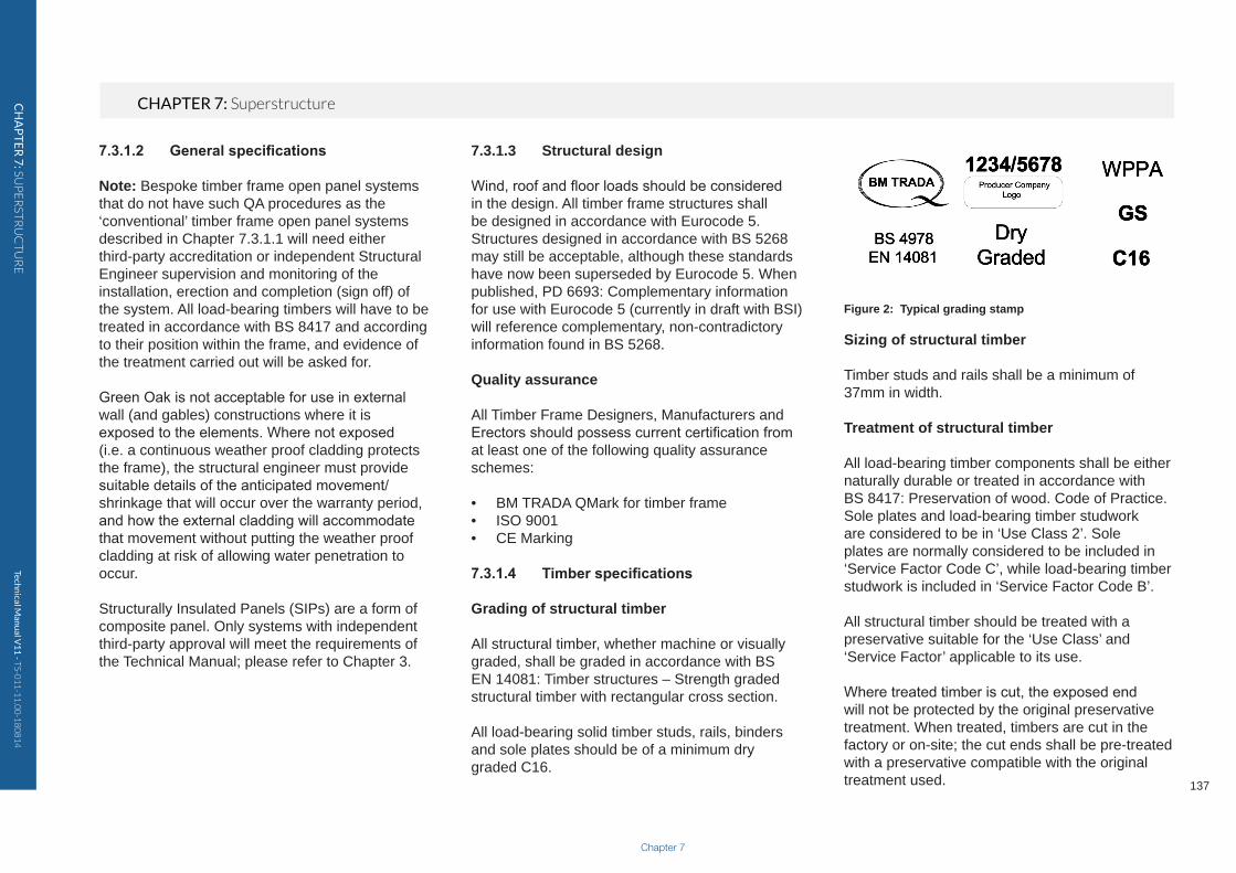
If ground conditions require gas membranes, they should be located so as not to inhibit drainage and ventilation to all areas of the timber frame structure.
Figure 5: Possible gas membrane detail
Techn
ical Man
ual V
11
- TS-0
11
-11
.00
-18
08
14
CHAPTER 7: SuperstructureCH
AP
TE
R 7
: SUP
ER
STR
UC
TU
RE
Chapter 7
143
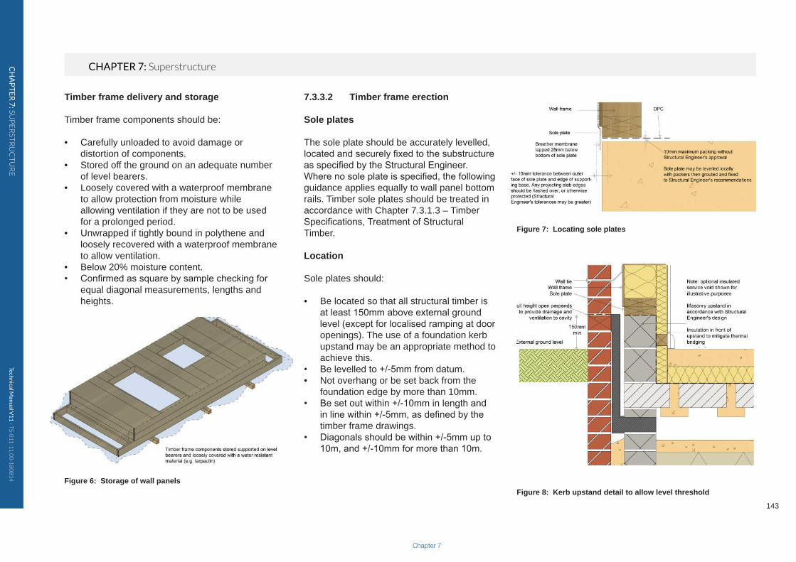
Timber frame delivery and storage
Timber frame components should be:
• Carefully unloaded to avoid damage or distortion of components.
• Stored off the ground on an adequate number of level bearers.
• Loosely covered with a waterproof membrane to allow protection from moisture while allowing ventilation if they are not to be used for a prolonged period.
• Unwrapped if tightly bound in polythene and loosely recovered with a waterproof membrane to allow ventilation.
• Below 20% moisture content.• Confirmed as square by sample checking for
equal diagonal measurements, lengths and heights.
Figure 6: Storage of wall panels
7.3.3.2 Timber frame erection
Sole plates
The sole plate should be accurately levelled, located and securely fixed to the substructure as specified by the Structural Engineer. Where no sole plate is specified, the following guidance applies equally to wall panel bottom rails. Timber sole plates should be treated in accordance with Chapter 7.3.1.3 – Timber Specifications, Treatment of Structural Timber.
Location
Sole plates should:
• Be located so that all structural timber is at least 150mm above external ground level (except for localised ramping at door openings). The use of a foundation kerb upstand may be an appropriate method to achieve this.
• Be levelled to +/-5mm from datum.• Not overhang or be set back from the
foundation edge by more than 10mm.• Be set out within +/-10mm in length and
in line within +/-5mm, as defined by the timber frame drawings.
• Diagonals should be within +/-5mm up to 10m, and +/-10mm for more than 10m.
Figure 7: Locating sole plates
Figure 8: Kerb upstand detail to allow level threshold

Techn
ical Man
ual V
11
- TS-0
11
-11
.00
-18
08
14
CHAPTER 7: SuperstructureCH
AP
TE
R 7
: SUP
ER
STR
UC
TU
RE
Damp Proof Course (DPC)
A DPC should:
• Be located directly below all timber sole plates bearing on other materials that may transfer moisture.
• Overlap at DPC junctions by at least 100mm.• Be located flush to the outside edge of the sole plate.
Packing
Structural shims or grout may be required under sole plates to level them and transfer vertical load. Longer sole plate to foundation fixings may be needed to allow for the size of the gap.
Structural shims should:
• Be non-compressible and inert.• Be located under every stud.• Provide an equal cross sectional area to the
studs they support.• Be located under sole plates to provide full
width bearing to studs.• Provide full bearing under point loads.• Not exceed a total of 10mm in height without a
Structural Engineer’s approval.
Structural grout should be:
• Considered for use by a Structural Engineer for gaps exceeding 10mm.
• Non-shrinkable.• Full bearing under sole plates.• Packed under the DPC.
Figure 9: Packing of sole plates
Note: The use of structural grout is not considered suitable for gaps less than 10mm due to installation difficulties.
Fixings
Fixings should:
• Be installed to the Structural Engineer’s specification.
• Not damage the substructure or sole plates during installation.
• Be placed to provide adequate lateral restraint at door openings.
• Be specified with consideration for use with gas membranes where appropriate.
Wall panel erection tolerances
Wall panels should be erected to the following tolerances:
• +/-10mm from plumb per storey height.• +/-10mm from plumb over the full height of the building.• +/-3mm from line of sole plate, with maximum
+/-5mm deviation from drawing.• +/-5mm from line at mid height of wall panel.• Inside faces of adjacent wall panels should be flush.• Adjacent wall panels should be tightly butted.
Figure 10: Wall panel erection tolerances

Techn
ical Man
ual V
11
- TS-0
11
-11
.00
-18
08
14
CHAPTER 7: SuperstructureCH
AP
TE
R 7
: SUP
ER
STR
UC
TU
RE
Chapter 7
145
Fixings and junctions
All fixings are to be installed to the Structural Engineer’s specification.
Unless otherwise justified:
• Junctions of wall panels and sole plates/head binders should not occur together.
• Head binder laps should wherever possible occur over a stud, preferably at least 600mm from the panel junction.
• Wall panel to wall panel connections should be a maximum of 300mm centres.
• Bottom rail to sole plate fixings should be one or two per stud bay.
• Wall panels should be adequately braced during erection to maintain tolerances.
• Disproportionate collapse fitting and fixings must be installed if specified.
• Multiple stud clusters must be installed to the full width of point load-bearings.
• Point loads must be transferred down through wall panels and floor zones to foundations.
• Closed panel walls manufactured off-site must be fixed together as specified.
• Closed panel walls should not be exposed for longer than necessary to avoid moisture ingress.
• Engineered timber components should not be exposed to moisture for longer periods than those stated by the manufacturer.
• Roof trusses/rafters should be adequately fixed to wall panels.
• Floor joists should be nailed down to wall panels.
• If no head binder is present, floor joists must bear directly over studs.
• Waistbands and alignment of floors over walls should remain within tolerances for wall panels.
Figure 11: Head binder lapping
Air leakage
Detailing and installation instructions must be followed to achieve adequate air tightness.
Figure 12: Typical floor zone air tightness detail

Techn
ical Man
ual V
11
- TS-0
11
-11
.00
-18
08
14
CHAPTER 7: SuperstructureCH
AP
TE
R 7
: SUP
ER
STR
UC
TU
RE
Breather membrane
Breather membrane should be:
• Lapped to deflect moisture away from the timber frame structure.
• Lapped by a minimum of 100mm at horizontal joints and a minimum of 150mm at vertical joints.
• Trimmed to leave a 25mm lap below the lowest timber sole plate.
• Repaired if damaged.
7.3.3.3 Cavity barriers
Location
In England and Wales, cavity barriers shall be installed:
• At the edges of all cavities, including around openings, e.g. windows, doors.
• Between an external cavity wall and a compartment wall or compartment floor.
• Around meter boxes in external walls.• Around service penetrations in external walls,
e.g. extract or boiler flue.• To sub-divide extensive cavities; please
refer to national regulations for specific requirements.
Figure 14: Locations of cavity barriers and open perpends
Figure 13: Lapping and repair of breather membraneNote: Cavity barriers may also be required between walls and floors within the building. Consult National Regulations for further guidance.

Techn
ical Man
ual V
11
- TS-0
11
-11
.00
-18
08
14
CHAPTER 7: SuperstructureCH
AP
TE
R 7
: SUP
ER
STR
UC
TU
RE
Chapter 7
147
• Allowance should be made for differential movement to occur at floor zones.
• Cavity barriers should be tightly fitting and remain effective in a fire.
• It should not retain or transmit moisture to cause the timber structure to exceed 20% moisture content.
• Its stated thermal performance should not be affected by cavity moisture. A breather membrane installed over the insulation may be required to assist in this.
• A method of installing wall ties through the insulation directly into the studs should be used.
7.3.4.2 Services
In addition to general provisions for the installation of services, the following are of particular note for timber frame construction external walls:
• The routing and termination of services should not affect the fire resistance of the structure.
• Electrical services are to be rated for their location with consideration for insulation.
• Wet services are not to be installed on the cold side of the insulation.
• Service penetrations through the VCL should be tight fitting to reduce air leakage and the passage of moisture vapour.
• Avoid running electrical services in the external wall cavity, except for meter tails.
• Services should be protected with metal plates if they pass within 25mm from face of stud.
to allow drainage and ventilation of the timber. The use of timber cavity barriers around openings allows for effective sealing to be installed between them and the opening frame.
7.3.4 Main contractor
7.3.4.1 Insulation
If insulation is specified between external walls studs, all voids shall be filled with insulation to maintain the thermal envelope of the building. When noggings or boards are installed between studs to support services or heavy fittings, the void behind them shall be fully insulated.
Insulation should not be installed until the structural timber frame is below 20% moisture content and the building is weather tight, as wet insulation can retain moisture. If closed panel timber frame is specified, additional care must be taken to protect the panels from exposure to moisture during construction.
If external wall insulation is to be used:
• Insulation should be installed in a manner to maintain its stated performance by minimising gaps that lead to thermal bridging and air washing.
• Installation should not allow external wall cavity moisture to become trapped between it and the timber frame.
• Cavity trays should be fixed and lapped to deflect cavity moisture away from the timber frame.
Installation
Cavity barriers shall be installed:
• So they fully close the cavity.• So the ends are tightly butted to form a
continuous barrier.• Backed by solid timber studs, rails or floor joist
at least 38mm wide.• In accordance with manufacturer or
independent certifier’s guidance.
A cavity tray should be proved directly above a horizontal cavity barrier, lapped at least 100mm behind the breather membrane (except at eaves and verges).
Figure 15: Cavity tray above horizontal cavity barrier
Timber cavity barriers should be protected from masonry cladding by the use of a DPC. The cavity face of the cavity barrier should be left uncovered

Techn
ical Man
ual V
11
- TS-0
11
-11
.00
-18
08
14
CHAPTER 7: SuperstructureCH
AP
TE
R 7
: SUP
ER
STR
UC
TU
RE
• Adequate allowance for differential movement to occur without causing damage should be provided for rigid services rising vertically through a building.
• Services that pass through the external wall cavity and provide an opening (such as flues/vents) should be enclosed with a cavity barrier and protected with a cavity tray.
Figure 16: Drilling of studs
7.3.4.3 Vapour Control Layer (VCL)
A VCL should not be installed until the structural timber frame is below 20% moisture content and the building is weather tight.
Installation
A sheet membrane (polythene or proprietary) VCL should be:
• Securely fixed to and cover all areas of the timber frame external walls, including all sole plates, head binders and window/door reveals.
• Lapped and sealed by at least 100mm at joints.• Lapped and sealed over studs, rails or
noggings.• Sealed around service penetrations.• Lapped and sealed fully into window and door
reveals.• Lapped and sealed with DPM/DPC at the
junction with the ground floor/foundation by a minimum of 100mm.
Note: Small holes in the VCL should be sealed with a suitable self-adhesive tape. If a proprietary membrane is being used, the manufacturer’s proprietary sealing tape should be used. Larger holes should be re-covered to lap over adjacent studs and rails.
Vapour control plasterboard should be:
• Fixed in accordance with the plasterboard manufacturer’s installation guidance.
• Tightly cut and fitted around service penetration.
• Discarded if the vapour control backing is damaged.
7.3.4.4 Plasterboard
Installation
In order to provide the specified period of fire resistance, the plasterboard must:
• Protect all areas of the timber frame structure.• Have all edges supported by timber studs or
rails.• Be fixed in accordance with the plasterboard
manufacturer’s guidance.• Be cut and tightly fit around service
penetrations.• Have junctions of wall and ceiling linings
detailed to maintain continuity.• Be installed using the specified number of
layers to achieve the required fire resistance.• Have all joints staggered when installing
multiple layers.
Fixing of plasterboard
When installing plasterboard linings:
• Each layer must be fully and independently fixed.
• Fixings of the correct length and centres should be installed in accordance with the plasterboard manufacturer’s installation instructions.
• Walls requiring plasterboard to provide racking resistance should be clearly identified with plasterboard installed to the Structural
Techn
ical Man
ual V
11
- TS-0
11
-11
.00
-18
08
14
CHAPTER 7: SuperstructureCH
AP
TE
R 7
: SUP
ER
STR
UC
TU
RE
Chapter 7
149
be maintained in addition to the insulation depth.In some locations, for example close to boundaries, National Regulations require claddings to provide fire resistance to the structure from the outside in.
Cavity barriers must be provided to meet National Regulations.
Self-supporting claddings (masonry)
Self-supporting (masonry) claddings should be connected to the timber frame using wall ties:
• Installed into studs provided around openings and movement joints, not just through sheathing.
• Angled to drain moisture away from the timber frame, even after differential movement has occurred.
• Installed at a minimum density of 4.4/m2 (a maximum of 375mm vertically with studs at 600mm centres and a maximum of 525mm vertically where studs are at 400mm centres). In accordance with BS 5268-6, closer centres may be required in exposed locations.
• Installed at a maximum of 300mm centres vertically and 225mm horizontally around openings and movement joints.
• Installed within 225mm of the head of a wall.
Cavity drainage and ventilation in masonry cladding should:
• Be provided with the use of full height open perpends at a maximum of 1350mm centres or equivalent open area.
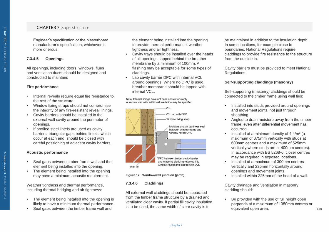
the element being installed into the opening to provide thermal performance, weather tightness and air tightness.
• Cavity trays should be installed over the heads of all openings, lapped behind the breather membrane by a minimum of 100mm. A flashing may be acceptable for some types of claddings.
• Lap cavity barrier DPC with internal VCL around openings. Where no DPC is used, breather membrane should be lapped with internal VCL.
Figure 17: Window/wall junction (jamb)
7.3.4.6 Claddings
All external wall claddings should be separated from the timber frame structure by a drained and ventilated clear cavity. If partial fill cavity insulation is to be used, the same width of clear cavity is to
Engineer’s specification or the plasterboard manufacturer’s specification, whichever is more onerous.
7.3.4.5 Openings
All openings, including doors, windows, flues and ventilation ducts, should be designed and constructed to maintain:
Fire performance
• Internal reveals require equal fire resistance to the rest of the structure.
• Window fixing straps should not compromise the integrity of any fire-resistant reveal linings.
• Cavity barriers should be installed in the external wall cavity around the perimeter of openings.
• If profiled steel lintels are used as cavity barriers, triangular gaps behind lintels, which occur at each end, should be closed with careful positioning of adjacent cavity barriers.
Acoustic performance
• Seal gaps between timber frame wall and the element being installed into the opening.
• The element being installed into the opening may have a minimum acoustic requirement.
Weather tightness and thermal performance, including thermal bridging and air tightness:
• The element being installed into the opening is likely to have a minimum thermal performance.
• Seal gaps between the timber frame wall and

Techn
ical Man
ual V
11
- TS-0
11
-11
.00
-18
08
14
CHAPTER 7: SuperstructureCH
AP
TE
R 7
: SUP
ER
STR
UC
TU
RE
joists should be considered. The building should be designed to ensure that differential movement occurs evenly to external elevations and the internal structure.
Figure 18: Differential movement at floor zones
Anticipated differential movement can be calculated using the allowance of 1mm for every 38mm of horizontal cross grain timber. As solid timber joists contribute significantly to anticipated differential movement, engineered timber joists should be considered where it is desirable to reduce differential movement.
Cavity drainage and ventilation should provide an open area of not less than 500mm2 per metre run:
• At the base of the external wall concealed space.
• Above horizontal cavity barriers/trays• Over openings in the external wall cavity, e.g.
windows and doors. • Allowing differential movement to occur while
retaining an adequate gap. • With openings protected by a mesh to prevent
the passage of insects.
Timber frame with external wall minimum cavity widths
Masonry 50mm
Render on unbacked lath 50mm
Render on backed lath or board 25mm
Timber 19mm
Tile hanging 25mm
Table 1: Minimum cavity widths
7.3.5 Differential movement
Appropriate allowances must be made for differential movement to occur without causing damage to the building.
Differential vertical movement occurs as a result of compression, closing of gaps and shrinkage of the timber frame structure, and occurs during the first 24 months following completion. Shrinkage occurs across the grain and is due to a reduction in the moisture content of timber elements. The shrinkage of plates, rails, binders, floor and roof
• Be fitted in the brick or block course below the lowest timber sole plate, above external finished ground level and below DPC.
• Be provided to ensure drainage and ventilation to each external wall concealed space, directly above horizontal cavity barriers/trays.
• Be installed over openings in the external wall cavity, e.g. windows and doors, at a maximum of 900mm centres.
• Maintain a clear cavity, with care taken to reduce mortar droppings at the base of the wall.
Weep-holes alone are unsuitable for timber frame construction, and open perpends should be used. Proprietary open perpend inserts are available with insect screening incorporated. Their equivalent open area must be considered.
In areas of severe or very severe exposure, check reveals should be constructed to provide additional weather protection.
Vertical loadings from masonry claddings must not be supported by the timber frame structure.
Claddings supported on the timber frame
Claddings supported on the timber frame should be connected to it on vertical treated timber battens, or a carrier system, to form a drained and ventilated cavity to all areas of the external timber frame wall. These should be fixed into structural timber, not just through the sheathing, to the Structural Engineer’s specification.

Techn
ical Man
ual V
11
- TS-0
11
-11
.00
-18
08
14
CHAPTER 7: SuperstructureCH
AP
TE
R 7
: SUP
ER
STR
UC
TU
RE
Chapter 7
151Figure 19: Anticipated differential movement dimensions
If fillers or seals are to be installed into differential movement gaps, their fully compressed dimension, considering the area of the seal and force required to compress it, must be added to the calculated gap size. Materials should be chosen to provide an effective weather tight seal dependant on whether they are to be subjected to compression, expansion or shear forces. Cover strips may also be used.
Self-supporting claddings (masonry)
Any material or component attached to the timber superstructure that overhangs the brick or blockwork (e.g. cladding attached to the timber frame, window sills, roof eaves and verges) or projects through the masonry (e.g. balcony supports, flues, extractor fan vents or overflow pipes) should have a clear gap beneath and at the top of the masonry cladding to allow differential movement to take place, thus avoiding damage to the component or cladding.
The size of the gap should be calculated by allowing 1mm for every 38mm of horizontal cross grain timber present between the gap location and the lowest structural timber. Gaps will therefore increase in size up the building. The dimensions provided in Figure 19 should be used if site-specific calculations have not been provided.

Techn
ical Man
ual V
11
- TS-0
11
-11
.00
-18
08
14
CHAPTER 7: SuperstructureCH
AP
TE
R 7
: SUP
ER
STR
UC
TU
RE
Masonry cladding should not be supported on the timber frame structure, but claddings do need to be supported.
Horizontal cross grain timber and construction gaps are concentrated at floor zones, and this is where the majority of movement occurs. Vertical timber battens or other rigid cladding support systems should not span over the floor zones of timber frame buildings. Gaps should be provided to accommodate anticipated differential movement. Unlike self-supporting claddings, movement is not cumulative but should be
Figure 22: Differential movement at verge
Figure 24: Differential movement at service penetration
Figure 20: Differential movement gap
Figure 21: Differential movement at eaves
Figure 23: Differential movement at cantilevered overhang
Techn
ical Man
ual V
11
- TS-0
11
-11
.00
-18
08
14
CHAPTER 7: SuperstructureCH
AP
TE
R 7
: SUP
ER
STR
UC
TU
RE
Chapter 7
153
Services
Rigid services within the timber frame structure also require an equal allowance for differential movement, as shown in Figure 19. Examples include copper gas and water pipes, dry risers, internal downpipes, SVPs and blockwork lift shafts. While gap allowances externally are allowed below, for example, a sill, when a branch comes off a rigid stack internally, the gap needs to be left above a service to allow the timber frame to drop around it.
7.3.6 References
• BS EN 1995-1-1: 2004+A1: 2008 Eurocode 5 Design of timber structures. General. Common rules and rules for buildings.
• BS 5268-2: 2002 Structural use of timber. Code of Practice for permissible stress design, materials and workmanship.
• BS 5268-3: 2006 Structural use of timber. Code of Practice for trussed rafter roofs.
• BS 5268-4 Section 4.1: 1978 Structural use of timber. Part 4 Fire resistance of timber structures. Section 4.1 Recommendations for calculating fire resistance of timber members.
• BS 5268-4 Section 4.2: 1990 Structural use of timber. Part 4 Fire resistance of timber structures. Section 4.2 Recommendations for calculating fire resistance of timber stud walls and joisted floor constructions.
• BS 5268-6.1: 1996 Structural use of timber. Code of Practice for timber frame walls. Dwellings not exceeding seven storeys.
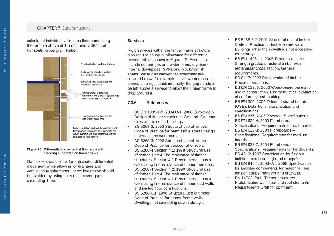
calculated individually for each floor zone using the formula above of 1mm for every 38mm of horizontal cross grain timber.
Figure 25: Differential movement at floor zone with cladding supported on timber frame
Gap sizes should allow for anticipated differential movement while allowing for drainage and ventilation requirements. Insect infestation should be avoided by using screens to cover gaps exceeding 4mm.
• BS 5268-6.2: 2001 Structural use of timber. Code of Practice for timber frame walls. Buildings other than dwellings not exceeding four storeys.
• BS EN 14081-1: 2005 Timber structures. Strength graded structural timber with rectangular cross section. General requirements.
• BS 8417: 2003 Preservation of timber. Recommendations.
• BS EN 13986: 2006 Wood-based panels for use in construction. Characteristics, evaluation of conformity and marking.
• BS EN 300: 2006 Oriented strand boards (OSB). Definitions, classification and specifications.
• BS EN 636: 2003 Plywood. Specifications.• BS EN 622-4: 2009 Fibreboards –
Specifications. Requirements for softboards.• BS EN 622-3: 2004 Fibreboards –
Specifications. Requirements for medium boards.
• BS EN 622-2: 2004 Fibreboards – Specifications. Requirements for hardboards.
• BS 4016: 1997 Specification for flexible building membranes (breather type).
• BS EN 845-1: 2003+A1: 2008 Specification for ancillary components for masonry. Ties, tension straps, hangers and brackets.
• EN 14732: 2011 Timber structures. Prefabricated wall, floor and roof elements. Requirements Draft for comment.