Embed Size (px)
Citation preview
I. INTRODUCTION
Two-stage-type ESPs (electrostatic precipitators) are
composed of both ionizers and collectors to which DC
high voltages are applied. Since these ESPs can collect
particles under the condition of relatively high wind-
velocity such as 9 m/s, they are widely adopted for
purifying tunnel-exhaust from motor-vehicles in which
the concentration of diesel-particles is high [1].
In order to decrease the phenomenon of abnormal
re-entrainment from the ESPs, the authors have been
studied the two-stage-type ESP with “bipolar corona
discharge” in which both positive corona and negative
corona are simultaneously generated. In the front-stage
ionizer, particles are charged positively and/or negatively,
and in the rear-stage collector, charged particles are
collected [2-5].
The principle is shown in Fig. 1. Each double-circle
in the ionizer represents the part of spike-tip at which
corona-discharge is taking place. The image is shown
that particles are charged in bipolarity at the ionizer and
they are caught not only on the grounded-plate but also
on the energized-plate.
The authors’ studies [2-4] have reported that the
case of the positive corona at windward and the negative
corona at leeward realizes higher collection-efficiency η
than the opposite case with the negative corona at
windward and the positive corona at leeward. In case of
the discharge-gap of 15 mm and power consumption of
2.8 W in the ionizer, for example, the efficiency η in case
of the positive corona at windward is approx. 80%
whereas approx. 70% of η in case of the negative corona
at windward.
In a comparison between a bipolar discharge ESP
and a mono-polar discharge ESP, the study reports that
some of the data have shown that the bipolar ESP
realizes higher efficiency η than the mono-polar ESP [4].
In case of 15 mm (gap) and 2.8 W in the ionizer, for
example, the efficiency η of mono-polar ESP with
positive discharge is approx. 75%. There is also another
study by the authors which reports that diesel-particles
can be caught on the energized-plates as much as on the
grounded-plates in the collectors of bipolar ESPs.
The purpose of this study is to clarify the
mechanism of particle-charging in bipolar corona-
discharge by measuring discharge current-density and
observing vestiges of soot-particles attached on both
electrode-plates in the bipolar ionizer.
Function of an electrostatic precipitator using bipolar corona discharges
A. Katatani1, H. Hosono1, H. Murata1 and A. Mizuno2
1Panasonic Ecology Systems Co., Ltd, Japan 2Department of Environmental and Life Sciences, Toyohashi University of Technology, Japan
Abstract—The discharge spikes in the ionizer of the ESP (electrostatic precipitator) with bipolar corona-discharge are arranged not only in the energized-plates but also in the grounded-plates. The discharge from the spikes in the grounded-plates generates ions of opposite polarity to those from the energized-plates. A two-stage-type ESP with bipolar-corona discharge is composed of the ionizer and a collector to which DC high voltage is applied. In the previous test, this bipolar collection method, using positive and negative discharges simultaneously, proved that the particles were enough collected. In this report, discharge-current-density and attached-particles on the ionizer-plates have been discussed in order to clarify the charging-mechanism in the bipolar discharge.
Keywords—Electrostatic precipitator, DC corona, positive discharge, negative discharge, spike, bipolar
Corresponding author: Atsushi Katatani e-mail address: [email protected] Presented at the 2012 Electrostatics Joint Conference June 12-14 2012, in Cambridge, Ontario (Canada)
Fig. 1. Principle of ESP with bipolar corona discharge.

II. METHODOLOGY
The shape of the electrode plates in the ionizer for
bipolar discharge is shown in Fig. 2. Ten spikes for
discharge are located on the edge of one side of a
stainless steel plate.
Fig. 3 shows the test system. The ionizer generates
bipolar discharge under the condition of ventilating the
air with diesel-particles.
Table I shows the specifications of the test
equipment.
The nine ionizer-plates, which are shown in Fig. 2,
are arranged in an ionizer-duct #1. The spike-tips of four
plates, to which DC +10 kV from a dc high voltage
power supply #4 is applied, are pointing to the windward.
The spike-tips of five plates, which are connected to the
ground, are pointing to the leeward. The plates of tip-to-
windward and the plates of tip-to-leeward are alternately
allocated in parallel with the gap of 15 mm. The distance
between each spike-tip and the nearest edge of the
adjoining plate on the projected plane is approximately
60 mm. This arrangement of the ionizer-plates produces
positive corona from the spikes of tip-to-windward and
negative corona from the spikes of tip-to-leeward.
Soot-particles generated from a diesel engine #2 are
supplied via nozzles to the windward of the ionizer-duct
#1. A fan #3 is for ventilation. Air velocity of “primary
wind” in the ionizer-duct #1 is 9 m/s. The output of the
diesel engine #2 is adjusted in order to keep the
concentration 0.5 mg/m3 of soot-particles. After the
operation of 16 h under these conditions, the ionizer-
plates are taken out and observed.
Both positive corona and negative corona are
simultaneously generated in the bipolar corona discharge.
Both coronas are accompanied with ionic wind as
“secondary wind”. Since it has been known that the
strength of ionic wind is proportion to the root of current
density [6], current density of the positive corona and the
negative corona were measured in order to evaluate the
interrelation between ionic wind and attached soot
particles on the ionizer-plates.
A set of electrode plates for measuring current
density is shown in Fig. 4 and 5. Fig. 4 is for a spike-
plate made of stainless steel to which dc high voltage of
positive or negative is applied. Fig. 5 shows the
grounded-plate on which aluminum tapes are separately
mounted to measure the current distribution. Nine
aluminum tapes of 10 mm (W), 108 mm (L) and 0.05
mm (t) are parallel put on a dielectric plate keeping the
distance of 2 mm between adjoining tapes, which makes
Area 1 to Area 9.
The test equipment for measuring current density is
shown in Fig. 6. The arrangement of these two plates is
that all the spikes are projected on the Area 5 on the
grounded-plate. The gap distance is 15 mm between the
two plates. The current of each part from Area 1 to Area
9 was measured with applying positive or negative dc 10
kV to the spike-plate.
The current density is obtained by dividing the
measured current by the aluminum tape area of 1,080
mm2. As shown in Fig. 6, a current meter is connected to
Area 2 whereas other eight areas are directly connected
to the ground. The current at the other areas can be
measured by switching the meter circuit. This test was
done under the condition of “no wind”.
Fig. 2. Ionizer-plate with spikes for bipolar discharge.
Fig. 3. Test system of the bipolar ionizer.

III. RESULTS AND DISCUSSION
Fig. 7 shows the vestiges which are obtained after
16 h operation of the bipolar ionizer with the air
containing diesel particles. It seems that all the vestiges
of attached particles are not the same but depending on
locations on both plates of the energized-plate and the
grounded-plate.
The distribution of current density in the nine areas
on the grounded-plate is shown in Fig. 8. The case of
applying negative voltage to the spike-plate generally
indicates larger current-density than the case of positive
voltage.
Fig. 4. Spike-plate for measuring current-density.
Fig.5. Grounded-plate for measuring current-density.
Fig. 6. Test system for measuring current-density.
TABLE I TEST EQIPMENT
Items Details
Ionizer duct (#1) W 121, H 140, L 600 [mm] (Inside)
Diesel engine
(#2) ISUZU 4BD1-1, 1200 rpm, fuel: diesel oil
Fan (#3)
MU1238A-11B (Oriental Motor Co.,Ltd. )
Quantity ; 2 (tandem coupled)
With a variable frequency controller
High voltage
power supply
(#4)
Tunnel-ESP power supply (Origin Electric)
Max. output ; DC +13 kV , 150 mA and
Ripple; 5 % or less
Wind velocity
meter
Climomaster MODEL6531 (Kanomax)
Mode;1 sec. measuring & 10 times ave.
Voltage meter
and probe
Digital multi meter type73303 (Yokogawa)
Ratio;1/1000 (FLUKE), For high voltage
Current meter Type 201133 (Yokogawa)
Range; 0.1, 0.3, 1, 3 mA
High voltage
power supply
Model-502 (Pulse Electric Engineering)
Max. output ; DC+25kV , 25mA
Stability 0.01%
High voltage
power supply
MODEL-600F (Pulse Electric Engineering)
Max. output ; DC-15kV , 30mA
Stability 0.005%
Microscope
(Optical)
Digital microscope VHX-100F (KEYENCE)
Lens; VH-Z25 (25-175 times)

The area, where the current-density was the
maximum, was Area 4 which was adjacent to the spike-
tips in both positive case and negative case. The current-
density at Area 5, which is the closest to the spike-tips,
was not the largest. It has been reported in the reference
[7] that the direction of ionic wind is equal to the
direction to which the spike-tips are pointing in both
cases of positive and negative voltage. Consequently the
area of maximum current-density might not be Area 5
but be just neighboring Area 4.
In order to observe the ionizer-plates after 16 h
operation more carefully, the characteristics of current
density distribution in Fig. 8 are superposed on both
ionizer-plates in Fig. 7. These are shown in Fig. 9 of the
grounded-plate and Fig. 10 of the energized-plate. The
locations of the nine areas and the adjacent spikes are
marked in white-color on both plates in these two figures.
Fig. 7. Vestiges of ionizer-plates after 16 h operation.
Fig. 8. Current density distribution in the ionizer.
Fig. 9. Positive current density on the grounded-plate.
Fig. 10. Negative current density on the energized-plate.

As the current density of Area 4 on the grounded-
plate in Fig. 9 is the largest, deep-black vestiges, which
are marked as ellipses of broken-lines, are left on the
plate by the secondary wind (ionic wind) by positive
discharge from the adjacent spike-tips. The current
density of Area 4 on the energized-plate in Fig. 10 is also
the largest. There are black (but non-deep-black) vestiges
(marked by ellipses of broken-lines on the plate) caused
by the secondary wind of negative discharge from the
adjacent spike-tips.
In the comparison between Area 4 in Fig. 9 and
Area 4 in Fig. 10, the vestiges by positive discharge in
Fig. 9 are smaller but darker than the vestiges by
negative discharge in Fig. 10. The reason of the smaller-
ellipse vestiges in case of positive discharge in Area 4 is
explained as the current density of positive discharge is
smaller than that of negative discharge.
In order to clarify why the vestiges by positive
discharge are darker than those of negative discharge, the
image of modes of particles in the bipolar-ionizer is
indicated in Fig. 11. Double-circle represents spike-tip of
the energized-plate and the grounded-plate.
At first, Particle 1, Particle 2 and Particle 3, which
are illustrated in black circles, reach to L0 point at the
inlet position of ionizer with ventilated primary-wind.
These three particles shortly arrive to L1 point, which is
in the discharge space of positive corona, and the three
are charged in positive. At this time, Particle 1, which is
located at the closest position to the grounded-plate, is
moved toward the grounded-plate by Secondary wind 1
(positive ionic wind) and the Coulomb force to be caught
on the grounded-plate. Although Particle 2 and Particle
3 fly to the leeward, they are also moved towards the
grounded-plate by the Coulomb force in due course of
passing L2 point.
Particle 2 and Particle 3 fly to L3 point which is
close to the spike of negative discharge, and almost all
the charged particles are positioned in the closest space
to the grounded-plate. This means that the concentration
of particles is high in this space. In other words, the
particle-concentration is low in the space of SP1 which is
close to L4 point on the energized-plate to which
Secondary wind 2 by negative discharge hits. As the
concentration of particles which were caught on the
energized-plate was low, therefore the vestiges of
collected soot by negative discharge were not so dark.
Fig. 12 shows three binarized-images which are
made from the microscope photos of Part A, Part B and
Part C on the grounded-plate. The photo of bottom-left
in Fig. 12 indicates the locations.
The binalization software of “Photo Filter” is used
and the obtained microscope-photos are converted into
black-and-white images. The threshold level of black or
white is Level 60 in total 256 levels. Black parts in the
binalized-images represent the caught diesel-particles on
the plate.
The image of Part C in Fig. 12 describes the part on
which secondary wind (ionic wind) by positive discharge
hits directly. It seems that many large and small spots
densely gather to become dark in the whole area. On the
other hand, the vestiges of Part A near to the center axis
are located on the position of approximate 15 mm
windward from Part C toward primary wind. “Black
streaks” with taper-shape are pointing to windward. Part
B shows the image of a place between Part C and Part A.
At the center area of Part B, relatively fewer particles are
caught, which might mean the boundary between Part C
and A.
In order to discuss the streak-vestige of Part A, Fig.
13 is introduced. Although both Part D and E in Fig. 13
are also located in Area 3, same as Part A, these two
parts are apart from the center axis indicated in a dashed
line.
Although both Part D and E also reflect the streak-
vestige like Part A, there is a big difference between
them. Whereas the streaks of Part A are pointing to the
just reverse direction to primary wind, the streaks of Part
D and E are pointing to the direction having the angle of
Fig. 11. Modes of particles in the bipolar-ionizer.

approximate 30 deg. to primary wind. As the pointing
directions of streaks in Part A, D and E are different, it is
concluded that the streak-vestiges are formed not by the
primary wind but by the secondary wind. The mechanism
of forming the streak-vestige in Part A might be
explained as the secondary wind hits the surface of the
grounded-plate in Area 4 and bends along the surface
with charging particles which have flowed from
windward along the surface-space on the grounded-plate.
Part F, G and H in Fig. 14 are also binalized-images
on the grounded-plate. The spot-vestiges are relatively
not so crowded on Part F and most part of G. As Part F
corresponds to L2 point in Fig. 11, some particles such as
Particle 2 which makes itself approach the grounded-
plate might be caught on the grounded-plate. Part H in
Fig. 14 indicates a spike for negative discharge on the
grounded-plate. Many particles stick to the spike whose
color has turned into deep-black. As the electric field
around negative spikes is strong, it seems that positive
charged particles are apt to be attached.
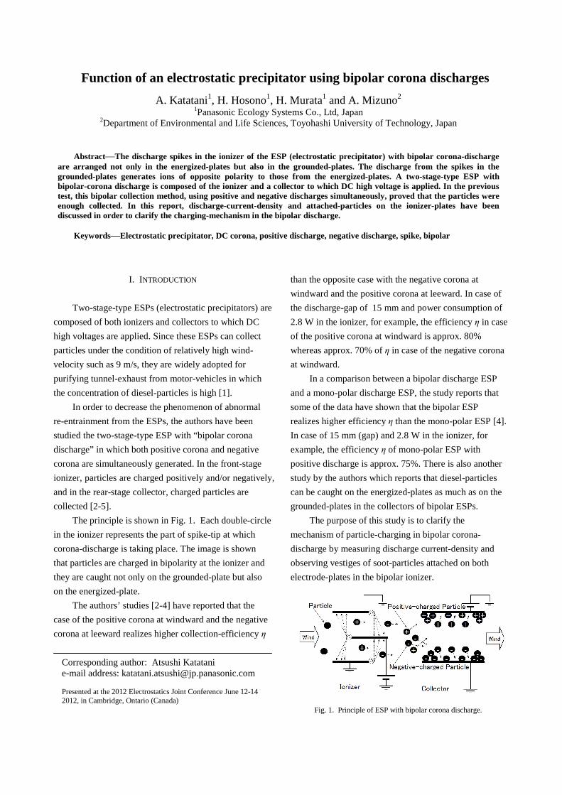
Fig. 15 shows three magnified pictures of Part J, K
and L on the energized-plate, although only Part J is not
binalized due to easier understanding.
Part J exhibits a spike for positive discharge. As the
surface of stainless-steel plate of Part J is clearly seen
without stuck particles, soot-particles are rarely caught
on the discharge-spikes located at windward. The stuck
particles on Part K are very few and those of Part L are
relatively few. A few re-entrained particles from the
grounded-plate might be attached on both parts. At this
moment, it should be noted that there is a deep-black area
between Part K and L. This area, called Part M later, is
discussed by using Fig. 16.
The reason for the deep-black part including Part M
in Fig. 16 might be due to the intense re-entrainment
from the grounded-plate. When the total area of this
deep-black part is surrounded by a white broken-line, the
zone exhibits “Arch shape” whose reason should be
further discussed. Although the velocity of primary wind
is 9 m/s average, there is a velocity distribution of
maximum speed 11 m/s at center axis and minimum
speed 8 m/s at edge as shown in Fig. 16. It is also noticed
that there is differential distance of 10 mm between the
Fig. 12. Observation of Part A, B and C on the grounded-plate.
Fig. 13. Observation of Part D and E on the grounded-plate.
Fig. 14. Observation of Part F, G and H on the grounded-plate.
start point of deep-black vestiges on the center axis and
the start point on the edge area due to the differential
wind-velocity 3 m/s between maximum speed and
minimum speed. Taking account of the gap distance 15
mm between the energized-plate and the grounded-plate,
the information such as the speed of re-entrained
particles can be obtained by using mathematical
calculation. The results of this calculation are as follows.
1) Flying velocity of re-entrained particles
(perpendicular vector to the plate); 4.5 m/s approx.
2) Time between the start of re-entrainment and the end
in catch on the opposite side; 1/300 s approx.
3) Generation point of re-entrainment on the grounded-
plate; Area 4 including Part C in Fig. 12.
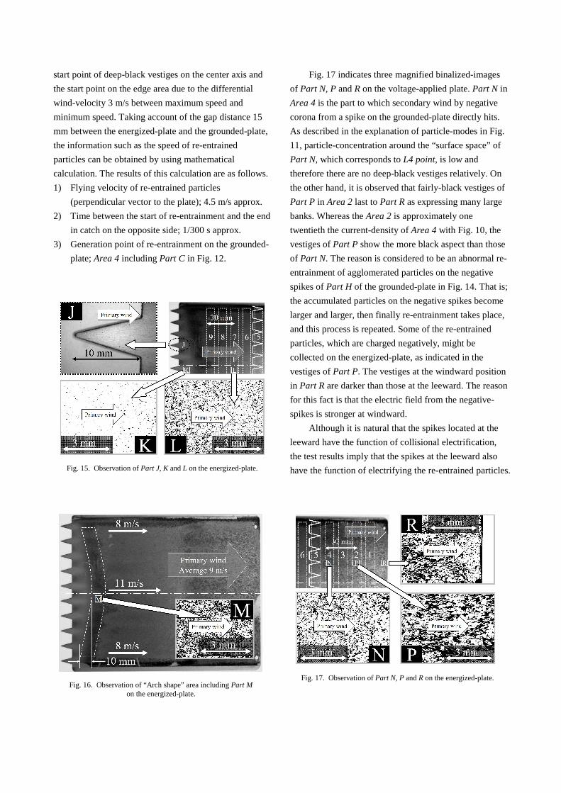
Fig. 17 indicates three magnified binalized-images
of Part N, P and R on the voltage-applied plate. Part N in
Area 4 is the part to which secondary wind by negative
corona from a spike on the grounded-plate directly hits.
As described in the explanation of particle-modes in Fig.
11, particle-concentration around the “surface space” of
Part N, which corresponds to L4 point, is low and
therefore there are no deep-black vestiges relatively. On
the other hand, it is observed that fairly-black vestiges of
Part P in Area 2 last to Part R as expressing many large
banks. Whereas the Area 2 is approximately one
twentieth the current-density of Area 4 with Fig. 10, the
vestiges of Part P show the more black aspect than those
of Part N. The reason is considered to be an abnormal re-
entrainment of agglomerated particles on the negative
spikes of Part H of the grounded-plate in Fig. 14. That is;
the accumulated particles on the negative spikes become
larger and larger, then finally re-entrainment takes place,
and this process is repeated. Some of the re-entrained
particles, which are charged negatively, might be
collected on the energized-plate, as indicated in the
vestiges of Part P. The vestiges at the windward position
in Part R are darker than those at the leeward. The reason
for this fact is that the electric field from the negative-
spikes is stronger at windward.
Although it is natural that the spikes located at the
leeward have the function of collisional electrification,
the test results imply that the spikes at the leeward also
have the function of electrifying the re-entrained particles.
Fig. 15. Observation of Part J, K and L on the energized-plate.
Fig. 16. Observation of “Arch shape” area including Part M on the energized-plate.
Fig. 17. Observation of Part N, P and R on the energized-plate.

IV. CONCLUSION
After 16 h of operation of the ionizer with bipolar
corona discharge (gap 15 mm and dc +10 kV) with
ventilating the air with diesel particles, pattern of the
collected soot particles on the electrode plates of the
ionizer were observed, together with the current
distribution of the grounded-electrode. From the test
results, following conclusions are obtained.
(1) The current density distribution shows the maximum
value at the area 10 mm far from the spike-tips on
the adjacent projected plane.
(2) When the secondary wind (ionic wind) from
discharge-spikes reaches the adjacent plate, the
secondary wind is hardly affected by the primary
wind.
(3) Some particles which are charged by positive corona
discharge from the spikes at windward accumulate
on the spikes of negative corona discharge at
leeward.
(4) The distribution of particle-concentration exists in
the inner-space of ionizer.
(5) Flying velocity of re-entrained particles
(perpendicular vector to the plate) is 4.5 m/s approx.
(6) The accumulated particles on the negative spikes at
leeward become larger to re-entrain finally and
repeat this process.
(7) The spikes at the leeward have the function of
electrifying the re-entrained particles.
REFERENCES [1] H. Hosono and A. Katatani, "Air purification system of
Matsushita Ecology Systems" (in Japanese), Journal of the Institute of Electrostatics Japan, vol. 32, pp. 203-206, 2008.
[2] A. Katatani and A. Mizuno: An ESP using bipolar-discharge with DC high voltage for road tunnels, XIIth International Conference on Electrostatic Precipitation at Nuernberg (ICESP XII), session 9 (2011)
[3] A. Katatani and A. Mizuno, “An ESP using bipolar-discharge with DC high voltage for road tunnels”, International Journal of Plasma Environmental Science Technology, vol.5, number 2, pp. 146-150, 2011
[4] A. Katatani and A. Mizuno, “2-stage-type Electrostatic Precipitators with Bipolar-discharge of DC-corona” (in Japanese), Journal of the Institute of Electrostatics Japan, vol.36, pp. 138-144, 2012.
[5] A. Katatani, H. Hosono, H. Murata, H. Yahata and A. Mizuno, “Two-stage-type Electrostatic Precipitator with Bipolar Corona Discharge” (in Japanese), Papers for Spring Presentation 2012 by the Institute of Electrostatics Japan at Tokyo, session 2p-5 (2012)
[6] K.Tanoue,H.Taniguchi,H.Masuda “Experimental study on both ionic wind and re-suspension of particles under unequal electrostatic field”, Advanced Power Technology , Vol.17 ,No.1(2006)p69-83
[7] A. Katatani and A. Mizuno, "Generation of ionic wind by using parallel located flat plates" (in Japanese), Journal of the Institute of Electrostatics Japan, vol.34, pp. 187-192, 2010.