Embed Size (px)
Citation preview
SINUMERIK
SINUMERIK 840D slPLC
Function Manual
Valid for:
Control systemSINUMERIK 840D sl / 840DE sl
SoftwareCNC software version 4.92
06/2019A5E47433877B AA
PrefaceFundamental safety instructions 1Overview 2PLC mode selector 3Reserve resources (timers, counters, FC, FB, DB, I/O) 4Commissioning hardware configuration of the PLC CPU 5Starting up the PLC program 6Coupling of the PLC CPU 7Interface structure 8Structure and functions of the basic program 9SPL for Safety Integrated 10Assignment overview 11PLC functions for HMI (DB19) 12PLC functions for drive components on the integrated PROFIBUS
13Memory requirements of the basic PLC program 14NC VAR selector 15Block descriptions 16Data lists 17Interface signals 18Appendix A
CNC software version 4.92

Legal informationWarning notice system
This manual contains notices you have to observe in order to ensure your personal safety, as well as to prevent damage to property. The notices referring to your personal safety are highlighted in the manual by a safety alert symbol, notices referring only to property damage have no safety alert symbol. These notices shown below are graded according to the degree of danger.
DANGERindicates that death or severe personal injury will result if proper precautions are not taken.
WARNINGindicates that death or severe personal injury may result if proper precautions are not taken.
CAUTIONindicates that minor personal injury can result if proper precautions are not taken.
NOTICEindicates that property damage can result if proper precautions are not taken.If more than one degree of danger is present, the warning notice representing the highest degree of danger will be used. A notice warning of injury to persons with a safety alert symbol may also include a warning relating to property damage.
Qualified PersonnelThe product/system described in this documentation may be operated only by personnel qualified for the specific task in accordance with the relevant documentation, in particular its warning notices and safety instructions. Qualified personnel are those who, based on their training and experience, are capable of identifying risks and avoiding potential hazards when working with these products/systems.
Proper use of Siemens productsNote the following:
WARNINGSiemens products may only be used for the applications described in the catalog and in the relevant technical documentation. If products and components from other manufacturers are used, these must be recommended or approved by Siemens. Proper transport, storage, installation, assembly, commissioning, operation and maintenance are required to ensure that the products operate safely and without any problems. The permissible ambient conditions must be complied with. The information in the relevant documentation must be observed.
TrademarksAll names identified by ® are registered trademarks of Siemens AG. The remaining trademarks in this publication may be trademarks whose use by third parties for their own purposes could violate the rights of the owner.
Disclaimer of LiabilityWe have reviewed the contents of this publication to ensure consistency with the hardware and software described. Since variance cannot be precluded entirely, we cannot guarantee full consistency. However, the information in this publication is reviewed regularly and any necessary corrections are included in subsequent editions.
Siemens AGDigital IndustriesPostfach 48 4890026 NÜRNBERGGERMANY
Document order number: A5E47433877B AAⓅ 06/2019 Subject to change
Copyright © Siemens AG 2019.All rights reserved

Preface
SINUMERIK documentation The SINUMERIK documentation is organized into the following categories:
● General documentation/catalogs
● User documentation
● Manufacturer/service documentation
Additional informationYou can find information on the following topics at the following address (https://support.industry.siemens.com/cs/de/en/view/108464614):
● Ordering documentation/overview of documentation
● Additional links to download documents
● Using documentation online (find and search in manuals/information)
If you have any questions regarding the technical documentation (e.g. suggestions, corrections), please send an e-mail to the following address (mailto:[email protected]).
mySupport/DocumentationAt the following address (https://support.industry.siemens.com/My/ww/en/documentation), you can find information on how to create your own individual documentation based on Siemens' content, and adapt it for your own machine documentation.
TrainingAt the following address (http://www.siemens.com/sitrain), you can find information about SITRAIN (Siemens training on products, systems and solutions for automation and drives).
FAQsYou can find Frequently Asked Questions in the Service&Support pages under Product Support (https://support.industry.siemens.com/cs/de/en/ps/faq).
SINUMERIKYou can find information about SINUMERIK at the following address (http://www.siemens.com/sinumerik).
PLCFunction Manual, 06/2019, A5E47433877B AA 3

Target groupThis publication is intended for:
● Project engineers
● Technologists (from machine manufacturers)
● System startup engineers (Systems/Machines)
● Programmers
BenefitsThe function manual describes the functions so that the target group knows them and can select them. It provides the target group with the information required to implement the functions.
Standard versionThis documentation only describes the functionality of the standard version. Extensions or changes made by the machine tool manufacturer are documented by the machine tool manufacturer.
Other functions not described in this documentation might be executable in the control. This does not, however, represent an obligation to supply such functions with a new control or when servicing.
Further, for the sake of simplicity, this documentation does not contain all detailed information about all types of the product and cannot cover every conceivable case of installation, operation or maintenance.
Note regarding the General Data Protection RegulationSiemens observes standard data protection principles, in particular the principle of privacy by design. That means that
this product does not process / store any personal data, only technical functional data (e.g. time stamps). If a user links this data with other data (e.g. a shift schedule) or stores personal data on the same storage medium (e.g. hard drive) and thus establishes a link to a person or persons, then the user is responsible for ensuring compliance with the relevant data protection regulations.
Technical SupportCountry-specific telephone numbers for technical support are provided in the Internet at the following address (https://support.industry.siemens.com/sc/ww/en/sc/2090) in the "Contact" area.
Preface
PLC4 Function Manual, 06/2019, A5E47433877B AA

Table of contents
Preface .........................................................................................................................................................3
1 Fundamental safety instructions.................................................................................................................25
1.1 General safety instructions.....................................................................................................25
1.2 Warranty and liability for application examples ......................................................................25
1.3 Industrial security ...................................................................................................................26
2 Overview.....................................................................................................................................................29
2.1 Brief description .....................................................................................................................29
2.2 Key data of the PLC CPU ......................................................................................................31
2.3 PLC operating system version ...............................................................................................32
3 PLC mode selector .....................................................................................................................................33
4 Reserve resources (timers, counters, FC, FB, DB, I/O) .............................................................................35
5 Commissioning hardware configuration of the PLC CPU...........................................................................37
6 Starting up the PLC program......................................................................................................................39
6.1 Installation of the basic program ............................................................................................39
6.2 Application of the basic program............................................................................................39
6.3 Version codes ........................................................................................................................40
6.4 Machine program ...................................................................................................................41
6.5 Data backup ...........................................................................................................................41
6.6 PLC series startup, PLC archive ............................................................................................42
6.7 Software upgrade...................................................................................................................47
6.8 I/O modules (FM, CP modules)..............................................................................................48
6.9 Troubleshooting .....................................................................................................................49
7 Coupling of the PLC CPU...........................................................................................................................51
7.1 General information................................................................................................................51
7.2 Properties of the PLC CPU ....................................................................................................51
7.3 Interface with integrated PLC.................................................................................................51
7.4 Diagnostic buffer on PLC .......................................................................................................53
8 Interface structure.......................................................................................................................................55
8.1 Interface .................................................................................................................................55
8.2 PLC/NCK interface.................................................................................................................55
8.3 Interface PLC/HMI..................................................................................................................62
PLCFunction Manual, 06/2019, A5E47433877B AA 5

8.4 PLC/MCP/HHU interface........................................................................................................68
9 Structure and functions of the basic program.............................................................................................71
9.1 Startup and synchronization of NCK PLC ..............................................................................73
9.2 Cyclic operation (OB1) ...........................................................................................................73
9.3 Time-interrupt processing (OB35)..........................................................................................75
9.4 Process-interrupt processing (OB 40) ...................................................................................76
9.5 Diagnostic alarm, module failure processing (OB82, OB86)..................................................76
9.6 Response to NCK failure........................................................................................................77
9.7 Functions of the basic program called from the user program...............................................78
9.8 Symbolic programming of user program with interface DB....................................................81
9.9 M decoding acc. to list............................................................................................................83
9.10 PLC machine data..................................................................................................................87
9.11 Configuration machine control panel, handheld unit, direct keys...........................................91
9.12 Switchover of machine control panel, handheld unit............................................................100
10 SPL for Safety Integrated .........................................................................................................................103
11 Assignment overview................................................................................................................................105
11.1 Block address range for PLC user program.........................................................................105
12 PLC functions for HMI (DB19) ..................................................................................................................109
12.1 Channel selection.................................................................................................................109
12.2 Program selection ................................................................................................................110
12.3 Activating the key lock..........................................................................................................113
12.4 Operating area numbers ......................................................................................................113
12.5 Screen numbers...................................................................................................................11312.5.1 Screen numbers: JOG, manual machine .............................................................................11412.5.2 Screen numbers: Reference point approach .......................................................................11912.5.3 Screen numbers: MDA.........................................................................................................11912.5.4 Screen numbers: AUTOMATIC............................................................................................12012.5.5 Screen numbers: Parameters operating area ......................................................................12012.5.6 Screen numbers: Program operating area...........................................................................12212.5.7 Screen numbers: Program manager operating area............................................................12212.5.8 Screen numbers: Diagnostics operating area ......................................................................122
12.6 HMI monitor..........................................................................................................................123
13 PLC functions for drive components on the integrated PROFIBUS .........................................................125
13.1 Overview ..............................................................................................................................125
13.2 Performing a start-up ...........................................................................................................125
13.3 Example ...............................................................................................................................126
Table of contents
PLC6 Function Manual, 06/2019, A5E47433877B AA
14 Memory requirements of the basic PLC program.....................................................................................129
15 NC VAR selector ......................................................................................................................................133
15.1 Overview ..............................................................................................................................133
15.2 Using NC VAR selector........................................................................................................13515.2.1 NC VAR selector user interface ...........................................................................................13515.2.2 Description of functions........................................................................................................13715.2.3 Editing projects.....................................................................................................................13815.2.4 Filtering the variable list .......................................................................................................13915.2.5 Specifying the project list .....................................................................................................14115.2.6 Deleting a variable from the project list ................................................................................14215.2.7 Alias name ...........................................................................................................................14315.2.8 Generating code...................................................................................................................14315.2.9 Transfer to STEP 7 ..............................................................................................................14515.2.10 Using TIA Portal ...................................................................................................................14615.2.11 Using SINAMICS parameters ..............................................................................................14615.2.12 Importing variables and parameters.....................................................................................14715.2.13 Startup, installation...............................................................................................................148
16 Block descriptions.....................................................................................................................................149
16.1 FB1: RUN_UP - basic program, start section.......................................................................149
16.2 FB2: GET - read NC variable ...............................................................................................157
16.3 FB3: PUT - write NC variables .............................................................................................165
16.4 FB4: PI_SERV - request PI service......................................................................................17316.4.1 List of available Pl services ..................................................................................................17716.4.2 PI service: ASUP .................................................................................................................17816.4.3 PI service: CANCEL.............................................................................................................17916.4.4 PI service: CONFIG .............................................................................................................18016.4.5 PI service: DIGION...............................................................................................................18016.4.6 PI service: DIGIOF ...............................................................................................................18016.4.7 PI service: FINDBL...............................................................................................................18116.4.8 PI service: LOGIN ................................................................................................................18116.4.9 PI service: LOGOUT ............................................................................................................18116.4.10 PI service: NCRES...............................................................................................................18216.4.11 PI service: SELECT .............................................................................................................18216.4.12 PI service: SETUDT .............................................................................................................18316.4.13 PI service: SETUFR .............................................................................................................18316.4.14 PI service: RETRAC.............................................................................................................18316.4.15 PI service: CRCEDN ............................................................................................................18416.4.16 PI service: CREACE ............................................................................................................18516.4.17 PI service: CREATO ............................................................................................................18516.4.18 PI service: DELECE .............................................................................................................18616.4.19 PI service: DELETO .............................................................................................................18616.4.20 PI service: MMCSEM ...........................................................................................................18616.4.21 PI service: TMCRTO ............................................................................................................18816.4.22 PI service: TMFDPL .............................................................................................................18916.4.23 PI service: TMFPBP.............................................................................................................19016.4.24 PI service: TMGETT.............................................................................................................19116.4.25 PI service: TMMVTL.............................................................................................................19216.4.26 PI service: TMPOSM............................................................................................................193
Table of contents
PLCFunction Manual, 06/2019, A5E47433877B AA 7
16.4.27 PI service: TMPCIT ..............................................................................................................19416.4.28 PI service: TMRASS ............................................................................................................19516.4.29 PI service: TRESMO ............................................................................................................19516.4.30 PI service: TSEARC.............................................................................................................19616.4.31 PI service: TMCRMT............................................................................................................19916.4.32 PI service: TMDLMT ............................................................................................................20016.4.33 PI service: POSMT...............................................................................................................20016.4.34 PI service: FDPLMT .............................................................................................................201
16.5 FB5: GETGUD - read GUD variable ....................................................................................202
16.6 FB7: PI_SERV2 - request PI service....................................................................................210
16.7 FB9: MtoN - operator panel switchover................................................................................211
16.8 FB10: Safety relay (SI relay) ................................................................................................216
16.9 FB11: Brake test ..................................................................................................................218
16.10 FB29: Signal recorder and data trigger diagnostics .............................................................224
16.11 FC2 : GP_HP - basic program, cyclic section ......................................................................227
16.12 FC3: GP_PRAL - basic program, interruptdriven section.....................................................229
16.13 FC5: GP_DIAG - basic program, diagnostic alarm and module failure................................231
16.14 FC6: TM_TRANS2 - transfer block for tool management and multitool ...............................233
16.15 FC7: TM_REV - transfer block for tool change with revolver ...............................................234
16.16 FC8: TM_TRANS - transfer block for tool management ......................................................238
16.17 FC9: ASUP - start of asynchronous subprograms ...............................................................244
16.18 FC10: AL_MSG - error and operating messages.................................................................247
16.19 FC12: AUXFU - call interface for user with auxiliary functions.............................................249
16.20 FC13: BHGDisp - display control for handheld unit .............................................................250
16.21 FC17: YDelta - star-delta switchover ...................................................................................254
16.22 FC18: SpinCtrl - spindle control ...........................................................................................257
16.23 FC19: MCP_IFM - transfer of MCP signals to interface .......................................................267
16.24 FC21: Transfer - data exchange NC/PLC ............................................................................27516.24.1 Function ...............................................................................................................................27516.24.2 Declaration of the function ...................................................................................................27516.24.3 Explanation of formal parameters ........................................................................................27616.24.4 Function 1, 2: Signals synchronized actions to / from Channel ...........................................27616.24.5 Function 3, 4: Fast data exchange PLC-NC ........................................................................27716.24.6 Function 5: Update control signals to channel .....................................................................28116.24.7 Function 6: Update control signals to axes ..........................................................................28216.24.8 Function 7: Update control signals to axes ..........................................................................282
16.25 FC22: TM_DIR - direction selection for tool management ...................................................283
16.26 FC24: MCP_IFM2 - transferring MCP signals to the interface .............................................285
16.27 FC25: MCP_IFT - transfer of MCP/OP signals to interface..................................................289
16.28 FC26: HPU_MCP - Transfer of the HT 8/HT 10 signals to the interface..............................292
Table of contents
PLC8 Function Manual, 06/2019, A5E47433877B AA

16.28.1 Overview of the NC/PLC interface signals of HT 8 ..............................................................29716.28.2 Overview of the NC/PLC interface signals of HT 8 ..............................................................299
16.29 FC1005: AG_SEND - transfers data to Ethernet CP............................................................299
16.30 FC1006: AG_RECV - receives data from the Ethernet CP ..................................................300
17 Data lists...................................................................................................................................................303
17.1 Machine data........................................................................................................................30317.1.1 Display machine data...........................................................................................................30317.1.2 NC-specific machine data ....................................................................................................30317.1.3 Channelspecific machine data .............................................................................................303
18 Interface signals .......................................................................................................................................305
18.1 Interface signals - overview..................................................................................................30518.1.1 Overview of the PLC blocks .................................................................................................30518.1.1.1 Organization blocks (OBs) ...................................................................................................30518.1.1.2 Function blocks (FBs) ..........................................................................................................30518.1.1.3 Function blocks (FCs) ..........................................................................................................30618.1.1.4 Data blocks (DBs) ................................................................................................................30718.1.1.5 Timer block...........................................................................................................................30818.1.2 Signals from/to the machine control panel ...........................................................................30818.1.2.1 M version, signals from the MCP: Input image ....................................................................30818.1.2.2 M version, signals to the MCP: Output image......................................................................30918.1.2.3 T version, signals from the MCP: Input image .....................................................................30918.1.2.4 T version, signals to the MCP: Output image.......................................................................31018.1.2.5 Slimline version, signals from the MCP: Input image...........................................................31018.1.2.6 Slimline version, signals to the MCP: Output image ............................................................31118.1.3 Signals from/to the handheld unit HT 2................................................................................31218.1.3.1 Signals from the handheld unit: Input image........................................................................31218.1.3.2 Signals to the handheld unit: Output image .........................................................................31218.1.4 Signals from/to the handheld unit HT 8................................................................................31418.1.4.1 Signals from the handheld unit HT 8: Input image ...............................................................31418.1.4.2 Signals to handheld terminal HT 8: Output image ...............................................................31418.1.5 Signals from/to the handheld unit HT 10..............................................................................31518.1.5.1 Signals from the handheld unit HT 10: Input image .............................................................31518.1.5.2 Signals to handheld terminal HT 10: Output image .............................................................31618.1.6 PLC alarms/messages .........................................................................................................31718.1.6.1 FC 10 alarms in the DB2 (FB1: "ExtendAIMsg" = FALSE) ..................................................31718.1.6.2 FC 10 alarms in the DB2 (FB1: "ExtendAIMsg" = TRUE) ....................................................32618.1.7 Signals from/to the NC, PLC and operating software ..........................................................33918.1.7.1 DB10, onboard inputs and outputs of the NC ......................................................................33918.1.7.2 DB10, general signals to the NC..........................................................................................34018.1.7.3 DB10, onboard inputs and outputs from the NC/operating software....................................34118.1.7.4 DB10, selection and status signals from the operating software .........................................34218.1.7.5 DB10, general signals from the NC......................................................................................34418.1.7.6 DB10, external digital NC inputs ..........................................................................................34518.1.7.7 DB10, external digital NC outputs ........................................................................................34618.1.7.8 DB10, external analog NC inputs.........................................................................................34718.1.7.9 DB10, external analog NC outputs.......................................................................................34818.1.7.10 DB10, external digital NC inputs and outputs ......................................................................34918.1.7.11 DB10, analog NC inputs and outputs...................................................................................35018.1.7.12 DB10, collision avoidance: Protection area active ...............................................................351
Table of contents
PLCFunction Manual, 06/2019, A5E47433877B AA 9
18.1.7.13 DB10, collision avoidance: Activate protection area ............................................................35118.1.7.14 DB10, extension, handwheel signals from the NC...............................................................35218.1.7.15 DB10, interface robot status.................................................................................................35318.1.7.16 DB10, interface robot status.................................................................................................35318.1.8 Mode group-specific signals.................................................................................................35318.1.8.1 DB11, mode signals 1 to the NC..........................................................................................35318.1.8.2 DB11, mode signals 1 from the NC......................................................................................35418.1.8.3 DB11, mode signals 2 to the NC..........................................................................................35518.1.8.4 DB11, mode signals 2 from NC............................................................................................35618.1.9 Safety Integrated (SPL)........................................................................................................35718.1.9.1 DB18, parameterization part ................................................................................................35718.1.9.2 DB18, data area / errors.......................................................................................................35718.1.9.3 DB18, additional data areas.................................................................................................35918.1.9.4 DB18, F_SENDDP sender ...................................................................................................36018.1.9.5 DB18, F_SENDDP receiver .................................................................................................36018.1.9.6 DB18, SPL user data ...........................................................................................................36118.1.9.7 DB18, data area / errors: Extended data area .....................................................................36218.1.9.8 DB18, additional data areas: Extended data area ...............................................................36418.1.9.9 DB18, F_SENDDP sender ...................................................................................................36518.1.9.10 DB18, F_RECDP receiver....................................................................................................36718.1.10 Control/status signals to/from operator panel (OP)..............................................................37118.1.10.1 DB19, signals to the operator panel (OP) ............................................................................37118.1.10.2 DB19, signals from the operator panel (OP) ........................................................................37318.1.10.3 DB19, sidescreen - interface for the MCP function ..............................................................37718.1.10.4 DB19, sidescreen - interface for the MCP function ..............................................................37718.1.11 Defining PLC alarms ............................................................................................................37818.1.11.1 DB20, NC machine data ......................................................................................................37818.1.12 Channel-specific signals ......................................................................................................37918.1.12.1 DB21 - DB30, control signals to the channel (1) ..................................................................37918.1.12.2 DB21 - DB30, control signals to the geometry axes ............................................................38118.1.12.3 DB21 - DB30, HMI signals to channel / OEM signals from/to channel ................................38318.1.12.4 DB21 - DB30, control signals from the geometry axes ........................................................38518.1.12.5 DB21 - DB30, change signals for auxiliary function transfer from the channel ...................38718.1.12.6 DB21 - DB30, transferred M and S functions:......................................................................38818.1.12.7 DB21 - DB30, transferred T/D/DL functions.........................................................................38918.1.12.8 DB21 - DB30, transferred H/F functions ..............................................................................39018.1.12.9 DB21 - DB30, decoded M signals ........................................................................................39118.1.12.10 DB21 - DB30, active G functions .........................................................................................39218.1.12.11 DB21 - DB30, protection areas from the channel ................................................................39318.1.12.12 DB21 - DB30, synchronous actions, signals from/to the channel ........................................39418.1.12.13 DB21 - DB30, control signals from/to the channel ...............................................................39518.1.12.14 DB21 - DB30, signals to the orientation axes ......................................................................39618.1.12.15 DB21 - DB30, signals from the orientation axes ..................................................................39818.1.12.16 DB21 - DB30, tool management functions from the channel ..............................................39918.1.12.17 DB21 - DB30, control signals from/to the channel (2)..........................................................40018.1.13 Axis/spindle signals..............................................................................................................40318.1.13.1 DB31 - DB61, signals to the axis/spindle .............................................................................40318.1.13.2 DB31 - DB61, signals from the axis/spindle.........................................................................40818.1.14 Safety Integrated..................................................................................................................41618.1.14.1 DB31 - DB61, Safety Control Channel (SCC)......................................................................41618.1.14.2 DB31 - DB61, Safety Info Channel (SIC) .............................................................................41618.1.15 Tool management ................................................................................................................417
Table of contents
PLC10 Function Manual, 06/2019, A5E47433877B AA

18.1.15.1 DB71, interface for loading/unloading the magazine ...........................................................41718.1.15.2 DB72, interface for the spindle as change position..............................................................41918.1.15.3 DB73, interface for the turret................................................................................................42118.1.16 Signals from/to the machine control panel and the handheld unit .......................................42318.1.16.1 DB77, signals from/to the MCP and the HHU ......................................................................42318.1.17 Signals for Ctrl-Energy .........................................................................................................42418.1.17.1 DB1000, energy-saving profiles ...........................................................................................42418.1.18 SENTRON PAC ...................................................................................................................42618.1.18.1 DB1001, SENTRON PAC ....................................................................................................42618.1.18.2 DB1001, SENTRON PAC, auxiliary devices........................................................................42818.1.19 Spindle temperature sensor .................................................................................................42918.1.19.1 DB1002: spindle temperature sensors.................................................................................42918.1.20 Interface to the tool management, extended area ...............................................................43118.1.20.1 DB1071, interface for loading/unloading the magazine Multitool .........................................43118.1.20.2 DB1072, interface for the spindle: Multitool .........................................................................43218.1.20.3 DB1073, interface for the turret: Multitool ............................................................................433
18.2 Interface signals - detailed description.................................................................................43418.2.1 DB10: NC, PLC and HMI .....................................................................................................43418.2.1.1 DB10 DBX0.0 - 7 (digital NC inputs 1 - 8: Lock) ..................................................................43418.2.1.2 DB10 DBX1.0 - 7 (digital NC inputs 1 - 8: Set) ....................................................................43518.2.1.3 DB10 DBX4.0 - 7 (digital NC outputs 1 - 8: Lock) ................................................................43518.2.1.4 DB10 DBX5.0 - 7 (digital NC outputs 1 - 8: Overwrite) ........................................................43618.2.1.5 DB10 DBX6.0 - 7 (digital NC outputs 1 - 8: Setting value)...................................................43618.2.1.6 DB10 DBX7.0 - 7 (digital NC outputs 1 - 8: Target) .............................................................43718.2.1.7 DB10 DBX56.1 (Emergency Stop).......................................................................................43818.2.1.8 DB10 DBX56.2 (acknowledge Emergency Stop).................................................................43818.2.1.9 DB10 DBX56.4 - 7 (key-operated switch position 0 - 3).......................................................43818.2.1.10 DB10 DBX58.0 - 7 (collision avoidance: Deactivate protection area group)........................43918.2.1.11 DB10 DBX60.0 - 7 (digital NC inputs 1 - 8: Actual value) ....................................................44018.2.1.12 DB10 DBX64.0 - 7 (digital NC outputs 1 - 8: Setpoint) ........................................................44118.2.1.13 DB10 DBX93.0 ... 7 (collision avoidance: Deactivate protection area group) ......................44118.2.1.14 DB10 DBX97.0 - 3 (channel number geometry axis handwheel 1)......................................44218.2.1.15 DB10 DBX98.0 - 3 (channel number geometry axis handwheel 2)......................................44318.2.1.16 DB10 DBX99.0 - 3 (channel number geometry axis handwheel 3)......................................44318.2.1.17 DB10 DBX100.0 - 4 (axis number handwheel 1) .................................................................44418.2.1.18 DB10 DBX100.5 (define handwheel 1 as contour handwheel) ............................................44418.2.1.19 DB10 DBX100.6 (handwheel 1 selected).............................................................................44518.2.1.20 DB10 DBX100.7 (machine axis handwheel 1) .....................................................................44618.2.1.21 DB10 DBX101.0 - 4 (axis number handwheel 2) .................................................................44618.2.1.22 DB10 DBX101.5 (define handwheel 2 as contour handwheel) ............................................44618.2.1.23 DB10 DBX101.6 (handwheel 2 selected).............................................................................44618.2.1.24 DB10 DBX101.7 (machine axis handwheel 2) .....................................................................44718.2.1.25 DB10 DBX102.0 - 4 (axis number handwheel 3) .................................................................44718.2.1.26 DB10 DBX102.5 (define handwheel 3 as contour handwheel) ............................................44718.2.1.27 DB10 DBX102.6 (handwheel 3 selected).............................................................................44718.2.1.28 DB10 DBX102.7 (machine axis handwheel 3) .....................................................................44718.2.1.29 DB10 DBX103.0 (remote diagnosis active)..........................................................................44718.2.1.30 DB10 DBX103.5 (AT box ready) ..........................................................................................44718.2.1.31 DB10 DBX103.6 (HMI temperature limit) .............................................................................44818.2.1.32 DB10 DBX103.7 (HMI battery alarm)...................................................................................44818.2.1.33 DB10 DBX104.7 (NC-CPU ready) .......................................................................................44818.2.1.34 DB10 DBX106.1 (Emergency Stop active) ..........................................................................449
Table of contents
PLCFunction Manual, 06/2019, A5E47433877B AA 11

18.2.1.35 DB10 DBX107.0 - 1 (probe actuated) ..................................................................................44918.2.1.36 DB10 DBX107.6 (NCU link active).......................................................................................44918.2.1.37 DB10 DBX108.3 (operating software ready)........................................................................45018.2.1.38 DB10 DBX108.5 (drives in cyclic operation) ........................................................................45018.2.1.39 DB10 DBX108.6 (drive ready)..............................................................................................45018.2.1.40 DB10 DBX108.7 (NC ready) ................................................................................................45018.2.1.41 DB10 DBX109.0 (NC alarm active)......................................................................................45118.2.1.42 DB10 DBX109.5 (heat sink temperature alarm, NCU).........................................................45118.2.1.43 DB10 DBX109.6 (air temperature alarm) .............................................................................45218.2.1.44 DB10 DBX109.7 (NC battery alarm) ....................................................................................45218.2.1.45 DB10 DBX110.0 - 113.7 (software cams: minus cam signal 1 to 32) ..................................45218.2.1.46 DB10 DBX114.0 - 117.7 (software cams: plus cam signal 1 to 32) .....................................45318.2.1.47 DB10 DBX122.0 - 7 (digital NC inputs 9 - 16: Lock) ............................................................45418.2.1.48 DB10 DBX123.0 - 7 (digital NC inputs 9 - 16: Set) ..............................................................45418.2.1.49 DB10 DBX124.0 - 7 (digital NC inputs 17 - 24: Lock) ..........................................................45418.2.1.50 DB10 DBX125.0 - 7 (digital NC inputs 17 - 24: Set) ............................................................45518.2.1.51 DB10 DBX126.0 - 7 (digital NC inputs 25 - 32: Lock) ..........................................................45518.2.1.52 DB10 DBX127.0 - 7 (digital NC inputs 25 - 32: Set) ............................................................45618.2.1.53 DB10 DBX128.0 - 7 (digital NC inputs 33 - 40: Lock) ..........................................................45618.2.1.54 DB10 DBX129.0 - 7 (digital NC inputs 33 - 40: Set) ............................................................45718.2.1.55 DB10 DBX130.0 - 7 (digital NC outputs 9 - 16: Lock) ..........................................................45718.2.1.56 DB10 DBX131.0 - 7 (digital NC outputs 9 - 16: Overwrite) ..................................................45718.2.1.57 DB10 DBX132.0 - 7 (digital NC outputs 9 - 16: Setting value).............................................45818.2.1.58 DB10 DBX133.0 - 7 (digital NC outputs 9 - 16: Target) .......................................................45918.2.1.59 DB10 DBX134.0 - 7 (digital NC outputs 17 - 24: Lock) ........................................................45918.2.1.60 DB10 DBX135.0 - 7 (digital NC outputs 17 - 24: Overwrite) ................................................46018.2.1.61 DB10 DBX136.0 - 7 (digital NC outputs 17 - 24: Setting value)...........................................46018.2.1.62 DB10 DBX137.0 - 7 (digital NC outputs 17 - 24: Target) .....................................................46118.2.1.63 DB10 DBX138.0 - 7 (digital NC outputs 25 - 32: Lock) ........................................................46118.2.1.64 DB10 DBX139.0 - 7 (digital NC outputs 25 - 32: Overwrite) ................................................46218.2.1.65 DB10 DBX140.0 - 7 (digital NC outputs 25 - 32: Setting value)...........................................46318.2.1.66 DB10 DBX141.0 - 7 (digital NC outputs 25 - 32: Target) .....................................................46318.2.1.67 DB10 DBX142.0 - 7 (digital NC outputs 33 - 40: Lock) ........................................................46418.2.1.68 DB10 DBX143.0 - 7 (digital NC outputs 33 - 40: Overwrite) ................................................46418.2.1.69 DB10 DBX144.0 - 7 (digital NC outputs 33 - 40: Setting value)...........................................46518.2.1.70 DB10 DBX145.0 - 7 (digital NC outputs 33 - 40: Target) .....................................................46618.2.1.71 DB10 DBX146.0 - 7 (analog NC inputs 1 - 8: Lock).............................................................46618.2.1.72 DB10 DBX147.0 - 7 (analog NC inputs 1 - 8: Target) ..........................................................46718.2.1.73 DB10 DBW148 - 162 (analog NC outputs 1 - 8: Setting value) ...........................................46718.2.1.74 DB10 DBX166.0 - 7 (analog NC outputs 1 - 8: Overwrite)...................................................46718.2.1.75 DB10 DBX167.0 - 7 (analog NC outputs 1 - 8: Target)........................................................46818.2.1.76 DB10 DBX168.0 - 7 (analog NC outputs 1 - 8: Lock)...........................................................46918.2.1.77 DB10 DBW170 - 184 (analog NC outputs 1 - 8: Setting value) ...........................................46918.2.1.78 DB10 DBX186.0 - 7 (digital NC inputs 9 - 16: Actual value) ................................................47018.2.1.79 DB10 DBX187.0 - 7 (digital NC inputs 17 - 24: Actual value) ..............................................47018.2.1.80 DB10 DBX188.0 - 7 (digital NC inputs 25 - 32: Actual value) ..............................................47118.2.1.81 DB10 DBX189.0 - 7 (digital NC inputs 33 - 40: Actual value) ..............................................47118.2.1.82 DB10 DBX190.0 - 7 (digital NC outputs 9 - 16: Setpoint) ....................................................47218.2.1.83 DB10 DBX191.0 - 7 (digital NC outputs 17 - 24: Setpoint) ..................................................47218.2.1.84 DB10 DBX192.0 - 7 (digital NC outputs 25 - 32: Setpoint) ..................................................47318.2.1.85 DB10 DBX193.0 - 7 (digital NC outputs 33 - 40: Setpoint) ..................................................47318.2.1.86 DB10 DBW194 - 208 (analog NC inputs 1 - 8: Actual value)...............................................474
Table of contents
PLC12 Function Manual, 06/2019, A5E47433877B AA

18.2.1.87 DB10 DBW210 - 224 (analog NC outputs 1 - 8: Setpoint) ...................................................47418.2.1.88 DB10 DBX226.0 - 233.7 (collision avoidance: Protection area active) ................................47518.2.1.89 DB10 DBX234.0 - 241.7 (collision avoidance: Activate protection area) .............................47618.2.1.90 DB10 DBX245.0 - 5 (Ethernet handwheel stationary)..........................................................47618.2.2 DB11: Mode group ...............................................................................................................47718.2.2.1 DB11 DBX0.0 (AUTOMATIC mode) ....................................................................................47718.2.2.2 DB11 DBX0.1 (MDI mode)...................................................................................................47718.2.2.3 DB11 DBX0.2 (JOG mode) ..................................................................................................47818.2.2.4 DB11 DBX0.4 (mode change inhibit) ...................................................................................47818.2.2.5 DB11 DBX0.5 (mode group stop) ........................................................................................47918.2.2.6 DB11 DBX0.6 (mode group stop, axes plus spindles) .........................................................47918.2.2.7 DB11 DBX0.7 (mode group reset) .......................................................................................48018.2.2.8 DB11 DBX1.0 (TEACH IN machine function) ......................................................................48018.2.2.9 DB11 DBX1.1 (REPOS machine function)...........................................................................48118.2.2.10 DB11 DBX1.2 (REF machine function) ................................................................................48118.2.2.11 DB11 DBX1.6 (single block, type B) ....................................................................................48118.2.2.12 DB11 DBX1.7 (single block, type A) ....................................................................................48218.2.2.13 DB11 DBX4.0 (AUTOMATIC mode selected)......................................................................48318.2.2.14 DB11 DBX4.1 (MDI mode selected) ....................................................................................48318.2.2.15 DB11 DBX4.2 (JOG mode selected)....................................................................................48318.2.2.16 DB11 DBX5.0 (TEACH IN machine function selected) ........................................................48318.2.2.17 DB11 DBX5.1 (REPOS machine function selected) ............................................................48418.2.2.18 DB11 DBX5.2 (REF machine function selected)..................................................................48418.2.2.19 DB11 DBX6.0 (AUTOMATIC mode active)..........................................................................48418.2.2.20 DB11 DBX6.1 (active MDI mode) ........................................................................................48518.2.2.21 DB11 DBX6.2 (JOG mode active)........................................................................................48518.2.2.22 DB11 DBX6.3 (mode group ready) ......................................................................................48518.2.2.23 DB11 DBX6.7 (all channels in the "Reset" state).................................................................48618.2.2.24 DB11 DBX7.0 (TEACH IN machine function active) ............................................................48618.2.2.25 DB11 DBX7.1 (REPOS machine function active) ................................................................48618.2.2.26 DB11 DBX7.2 (REF machine function active)......................................................................48618.2.3 DB18: Safety Integrated, SPL ..............................................................................................48718.2.3.1 DB18 DBB36.0 (SPL_READY) ............................................................................................48718.2.3.2 DB18 DBB36.1 (STOP_E) ...................................................................................................48718.2.3.3 DB18 DBB38 - 41 (SPL inputs, SPL_DATA.INSEP[1...32]).................................................48718.2.3.4 DB18 DBB42.0 - 45.7 (SPL inputs, SPL_DATA.INSEP[33...64]).........................................48818.2.3.5 DB18 DBB46.0 - 49.7 (SPL outputs, SPL_DATA.OUTSEP[1...32]......................................48818.2.4 DB19: Operator panel ..........................................................................................................48918.2.4.1 DB19 DBX0.0 (brighten screen)...........................................................................................48918.2.4.2 DB19 DBX0.1 (darken screen).............................................................................................48918.2.4.3 DB19 DBX0.2 (key lock) ......................................................................................................49018.2.4.4 DB19 DBX0.3 (delete cancel alarms) ..................................................................................49018.2.4.5 DB19 DBX0.4 (delete recall alarms) ....................................................................................49118.2.4.6 DB19 DBX0.7 (actual values in the WCS) ...........................................................................49118.2.4.7 DB19 DBB6 (analog spindle 1, utilization as a percentage) ................................................49118.2.4.8 DB19 DBB7 (analog spindle 2, utilization as a percentage) ................................................49118.2.4.9 DB19 DBB8 (channel number).............................................................................................49218.2.4.10 DB19 DBB10 (PLC hardkeys)..............................................................................................49218.2.4.11 DB19 DBX13.5 (NC program: unload) .................................................................................49218.2.4.12 DB19DBX13.6 (NC program: load) ......................................................................................49218.2.4.13 DB19 DBX13.7 (NC program: selection)..............................................................................49218.2.4.14 DB19 DBX14.0 - 6 (PLC index)............................................................................................493
Table of contents
PLCFunction Manual, 06/2019, A5E47433877B AA 13

18.2.4.15 DB19 DBX14.7 (selects the file system) ..............................................................................49318.2.4.16 DB19 DBB15 (PLC line offset) .............................................................................................49318.2.4.17 DB19 DBB16 (program selection from the PLC: Index of the program list) .........................49318.2.4.18 DB19 DBB17 (program selection from the PLC: Program index in the program list)...........49418.2.4.19 DB19 DBX20.1 (screen is dark) ...........................................................................................49518.2.4.20 DB19 DBX20.3 (cancel alarms deleted) ..............................................................................49518.2.4.21 DB19 DBX20.4 (recall alarms deleted) ................................................................................49518.2.4.22 DB19 DBX20.6 (simulation active).......................................................................................49618.2.4.23 DB19 DBX20.7 (switch MCS/WCS) .....................................................................................49618.2.4.24 DB19 DBB22 (actual channel number) ................................................................................49618.2.4.25 DB19 DBW24 (current screen number) ...............................................................................49618.2.4.26 DB19 DBX26.1 (program selection from the PLC: Job completed) .....................................49718.2.4.27 DB19 DBX26.2 (program selection from the PLC: Error).....................................................49718.2.4.28 DB19 DBX26.3 (program selection from the PLC: Active)...................................................49718.2.4.29 DB19 DBX26.5 (program selection from the PLC: Unload) .................................................49818.2.4.30 DB19 DBX26.6 (program selection from the PLC: Load).....................................................49818.2.4.31 DB19 DBX26.7 (program selection from the PLC: Selection)..............................................49918.2.4.32 DB19 DBB27 (program selection from the PLC: Error detection) ........................................49918.2.4.33 DB19 DBX32.0 - 5 (function number) ..................................................................................50018.2.4.34 DB19 DBX32.6 (function request)........................................................................................50118.2.4.35 DB19 DBX32.7 (status)........................................................................................................50118.2.4.36 DB19 DBB33 - 35 (parameter 1 - 3).....................................................................................50118.2.4.37 DB19 DBB36 (error identification)........................................................................................50218.2.5 DB21, ...: Channel................................................................................................................50218.2.5.1 DB21, ... DBX0.1 (RESU: backward/forward) .....................................................................50218.2.5.2 DB21, ... DBX0.2 (RESU: start retrace support) ..................................................................50318.2.5.3 DB21, ... DBX0.3 (activate handwheel offset (DRF)) ...........................................................50318.2.5.4 DB21, ... DBX0.4 (activate single block) ..............................................................................50318.2.5.5 DB21, ... DBX0.5 (activate M01) ..........................................................................................50418.2.5.6 DB21, ... DBX0.6 (activate dry run feedrate)........................................................................50418.2.5.7 DB21, ... DBX1.0 (activate referencing) ...............................................................................50518.2.5.8 DB21, ... DBX2.1 (disable all synchronized actions)............................................................50618.2.5.9 DB21, ... DBX1.3 (time monitoring active) ...........................................................................50618.2.5.10 DB21, ... DBX1.4 (clearance control (CLC): stop)................................................................50618.2.5.11 DB21, ... DBX1.5 (clearance control (CLC): Override).........................................................50718.2.5.12 DB21, ... DBX1.6 (PLC action completed) ...........................................................................50718.2.5.13 DB21, ... DBX1.7 (activate program test (PRT)) ..................................................................50818.2.5.14 DB21, ... DBX2.0 ... 7 (activate "skip block" (SKP)) .............................................................50918.2.5.15 DB21, ... DBX3.0 (stroke enable).........................................................................................51018.2.5.16 DB21, ... DBX3.1 (punch interface 1: Manual stroke initiation) ............................................51018.2.5.17 DB21, ... DBX3.2 (stroke suppression) ................................................................................51118.2.5.18 DB21, ... DBX3.3 (delayed stroke) .......................................................................................51118.2.5.19 DB21, ... DBX3.4 (stroke inoperative) ..................................................................................51118.2.5.20 DB21, ... DBX3.5 (punch interface 2: Manual stroke initiation) ............................................51218.2.5.21 DB21, ... DBB4 (path feedrate override) ..............................................................................51218.2.5.22 DB21, ... DBB5 (path rapid traverse override) .....................................................................51418.2.5.23 DB21, ... DBX6.0 (feedrate disable).....................................................................................51618.2.5.24 DB21, ... DBX6.1 (read-in disable).......................................................................................51718.2.5.25 DB21, ... DBX6.2 (delete distance-to-go, channel-specific) .................................................51818.2.5.26 DB21, ... DBX6.4 (program level abort) ...............................................................................51818.2.5.27 DB21, ... DBX6.6 (path rapid traverse override active) ........................................................51918.2.5.28 DB21, ... DBX6.7 (path feedrate override active).................................................................519
Table of contents
PLC14 Function Manual, 06/2019, A5E47433877B AA

18.2.5.29 DB21, ... DBX7.0 (NC start disable).....................................................................................51918.2.5.30 DB21, ... DBX7.1 (NC Start).................................................................................................52018.2.5.31 DB21, ... DBX7.2 (NC Stop at the block limit) ......................................................................52018.2.5.32 DB21, ... DBX7.3 (NC Stop).................................................................................................52118.2.5.33 DB21, ... DBX7.4 (NC Stop axes plus spindles) ..................................................................52218.2.5.34 DB21, ... DBX7.7 (reset) ......................................................................................................52218.2.5.35 DB21, ... DBX8.0 - 9.1 (activate machine-related protection zone 1 - 10) ...........................52318.2.5.36 DB21, ... DBX10.0 - 11.1 (activate channel-specific protection zone 1 - 10) .......................52418.2.5.37 DB21, ... DBX12.0 - 2 (geometry axis 1: activate handwheel) .............................................52418.2.5.38 DB21, ... DBX12.3, 16.3, 20.3 (feedrate stop, geometry axes 1 / 2 / 3)...............................52518.2.5.39 DB21, ... DBX12.4 (geometry axis 1: traversing key lock) ...................................................52618.2.5.40 DB21, ... DBX12.5 (geometry axis 1: rapid traverse override) .............................................52618.2.5.41 DB21, ... DBX12.6 - 7 (geometry axis 1: traversing keys "Plus" / "Minus") ..........................52718.2.5.42 DB21, ... DBX13.0 - 6 (geometry axis 1: machine function request)....................................52918.2.5.43 DB21, ... DBX15.0 (geometry axis 1: invert handwheel direction of rotation) ......................53018.2.5.44 DB21, ... DBX16.0 - 2 (geometry axis 2: activate handwheel) .............................................53018.2.5.45 DB21, ... DBX16.4 (geometry axis 2: traversing key lock) ...................................................53118.2.5.46 DB21, ... DBX16.5 (geometry axis 2: rapid traverse override) .............................................53118.2.5.47 DB21, ... DBX16.6 - 7 (geometry axis 2: traversing keys "Plus" / "Minus") ..........................53118.2.5.48 DB21, ... DBX17.0 - 6 (geometry axis 2: machine function request)....................................53118.2.5.49 DB21, ... DBX19.0 (geometry axis 2: invert handwheel direction of rotation) ......................53118.2.5.50 DB21, ... DBX20.0 - 2 (geometry axis 3: activate handwheel) .............................................53118.2.5.51 DB21, ... DBX20.4 (geometry axis 3: traversing key lock) ...................................................53118.2.5.52 DB21, ... DBX20.5 (geometry axis 3: rapid traverse override) .............................................53218.2.5.53 DB21, ... DBX20.6 - 7 (geometry axis 3: traversing keys "Plus" / "Minus") ..........................53218.2.5.54 DB21, ... DBX21.0 - 6 (geometry axis 3: machine function request)....................................53218.2.5.55 DB21, ... DBX23.0 (geometry axis 3: invert handwheel direction of rotation) ......................53218.2.5.56 DB21, ... DBX24.3 (handwheel offset (DRF) requested) .....................................................53218.2.5.57 DB21, ... DBX24.4 (select NC-associated M01) ..................................................................53318.2.5.58 DB21, ... DBX24.5 (M01 requested) ....................................................................................53318.2.5.59 DB21, ... DBX24.6 (dry run feedrate selected).....................................................................53418.2.5.60 DB21, ... DBX25.3 (feedrate override selected for rapid traverse).......................................53418.2.5.61 DB21, ... DBX25.7 (program test (PRT) requested).............................................................53518.2.5.62 DB21, ... DBX26.0 ... 7 ("Skip block" (SKP) selected) .........................................................53618.2.5.63 DB21, ... DBX29.0 - 3 (activate fixed feedrate 1 - 4, path/geometry axes) ..........................53718.2.5.64 DB21, ... DBX29.4 (activate PTP travel) ..............................................................................53818.2.5.65 DB21, ... DBX29.5 (tool manager: Deactivate workpiece counter) ......................................53818.2.5.66 DB21, ... DBX29.6 (tool manager: Deactivating wear monitoring) .......................................53918.2.5.67 DB21, ... DBX29.7 (tool manager: Tool lock not active).......................................................53918.2.5.68 DB21 ... DBX30.0 - 2 (activate contour handwheel) ............................................................54018.2.5.69 DB21, ... DBX30.3 (simulation contour handwheel: Activate) ..............................................54018.2.5.70 DB21, ... DBX30.4 (simulation contour handwheel: Negative direction) ..............................54118.2.5.71 DB21, ... DBX30.5 (activate M0 / M1 associated with NC) ..................................................54118.2.5.72 DB21, ... DBX30.6 (JOG circular travel)...............................................................................54218.2.5.73 DB21, ... DBX31.0 - 2 (REPOS mode).................................................................................54218.2.5.74 DB21, ... DBX31.4 (REPOS activation)................................................................................54318.2.5.75 DB21, ... DBX31.5 (contour handwheel: invert handwheel direction of rotation) .................54418.2.5.76 DB21, ... DBX32.1 (RESU: retrace mode active).................................................................54418.2.5.77 DB21, ... DBX32.2 (retrace support active)..........................................................................54418.2.5.78 DB21, ... DBX32.3 (action block active) ...............................................................................54518.2.5.79 DB21, ... DBX32.4 (approach block active)..........................................................................54518.2.5.80 DB21, ... DBX32.5 (M00/M01 active) ...................................................................................545
Table of contents
PLCFunction Manual, 06/2019, A5E47433877B AA 15
18.2.5.81 DB21, ... DBX32.6 (last action block active) ........................................................................54618.2.5.82 DB21, ... DBX33.0 (referencing active) ................................................................................54618.2.5.83 DB21, ... DBX33.2 (revolutional feedrate active) .................................................................54618.2.5.84 DB21, ... DBX33.3 (handwheel override active)...................................................................54718.2.5.85 DB21, ... DBX33.4 (block search active)..............................................................................54718.2.5.86 DB21, ... DBX33.5 (M02 / M30 active) .................................................................................54718.2.5.87 DB21, … DBX33.6 (transformation active) ..........................................................................54918.2.5.88 DB21, ... DBX33.7 (program test active)..............................................................................54918.2.5.89 DB21, ... DBX35.0 (program state "running").......................................................................55018.2.5.90 DB21, ... DBX35.1 (program state "wait") ............................................................................55018.2.5.91 DB21, ... DBX35.2 (program state "stopped") ......................................................................55118.2.5.92 DB21, ... DBX35.3 (program state "interrupted") .................................................................55218.2.5.93 DB21, ... DBX35.4 (program state "aborted") ......................................................................55218.2.5.94 DB21, ... DBX35.5 (channel state "active") ..........................................................................55318.2.5.95 DB21, ... DBX35.6 (channel state "interrupted") ..................................................................55418.2.5.96 DB21, ... DBX35.7 (channel state "reset") ...........................................................................55418.2.5.97 DB21, ... DBX36.2 (all axes that have to be referenced have been referenced) .................55518.2.5.98 DB21, ... DBX36.3 (all axes stationary)................................................................................55518.2.5.99 DB21, ... DBX36.4 (interrupt handling active) ......................................................................55618.2.5.100 DB21, ... DBX36.5 (channel ready)......................................................................................55618.2.5.101 DB21, ... DBX36.6 (channel-specific NC alarm active) ........................................................55618.2.5.102 DB21, ... DBX36.7 (NC alarm with machining stop active) ..................................................55718.2.5.103 DB21, ... DBX37.0 - 2 (contour handwheel active) ..............................................................55718.2.5.104 DB21, ... DBX37.3 (clearance control (CLC): Active)...........................................................55818.2.5.105 DB21, ... DBX37.4 (clearance control (CLC): Stop at the lower motion limit) ......................55818.2.5.106 DB21, ... DBX37.5 (clearance control (CLC): Stop at the upper motion limit)......................55818.2.5.107 DB21, ... DBX37.6 (read-in disable is ignored) ....................................................................55918.2.5.108 DB21, ... DBX37.7 (stop at block end is ignored during single block (SBL))........................56018.2.5.109 DB21, ... DBX38.0 (stroke initiation active) ..........................................................................56018.2.5.110 DB21, ... DBX38.1 (manual stroke initiation: Acknowledgment) ..........................................56018.2.5.111 DB21, ... DBX39.1 (NC alarm with program stop)................................................................56118.2.5.112 DB21, ... DBX39.5 (Contour handwheel: handwheel direction of rotation inversion active)....56118.2.5.113 DB21, ... DBX40.0 - 2 (geometry axis 1: handwheel active) ................................................56218.2.5.114 DB21, ... DBX40.4 - 5 (geometry axis 1: traversing request "Plus" / "Minus") .....................56318.2.5.115 DB21, ... DBX40.6 - 7 (geometry axis 1: traversing command "Plus" / "Minus")..................56318.2.5.116 DB21, ... DBX41.0 - 6 (geometry axis 1: active machine function) ......................................56418.2.5.117 DB21, ... DBX43.0 (geometry axis 1: handwheel direction of rotation inversion active) ......56418.2.5.118 DB21, ... DBX46.0 - 2 (geometry axis 2: handwheel active) ................................................56518.2.5.119 DB21, ... DBX46.4 - 5 (geometry axis 2: traversing request "Plus" / "Minus") .....................56518.2.5.120 DB21, ... DBX46.6 - 7 (geometry axis 2: traversing command "Plus" / "Minus")..................56518.2.5.121 DB21, ... DBX47.0 - 6 (geometry axis 2: active machine function) ......................................56518.2.5.122 DB21, ... DBX49.0 (geometry axis 2: handwheel direction of rotation inversion active) ......56518.2.5.123 DB21, ... DBX52.0 - 2 (geometry axis 3: handwheel active) ................................................56618.2.5.124 DB21, ... DBX52.4 - 5 (geometry axis 3: traversing request "Plus" / "Minus") .....................56618.2.5.125 DB21, ... DBX52.6 - 7 (geometry axis 3: traversing command "Plus" / "Minus")..................56618.2.5.126 DB21, ... DBX53.0 - 6 (geometry axis 3: active machine function) ......................................56618.2.5.127 DB21, ... DBX55.0 (geometry axis 3: handwheel direction of rotation inversion active) ......56618.2.5.128 DB21, ... DBB58, DBB60 - 65 (M-, S-, T-, D-, H-, F fct. change) .........................................56618.2.5.129 DB21, ... DBX59.0 - 4 (M fct. 1-5 not decoded) ...................................................................56718.2.5.130 DB21, ... DBB60 - 64, ... DBB66 - 67 (M-, S-, T-, D-, H-, F fct. Additional quick information
(quick acknowledgment) ......................................................................................................56718.2.5.131 DB21, ... DBB68 - 97 (M function 1 - 5 and extended address M function 1 - 5 ) ................567
Table of contents
PLC16 Function Manual, 06/2019, A5E47433877B AA
18.2.5.132 DB21, ... DBB98 - 115 (S function 1 - 3 and extended address S function 1 - 3 ) ...............56818.2.5.133 DB21, ... DBB118 (T function 1)...........................................................................................56818.2.5.134 DB21, ... DBB129 (D function 1) ..........................................................................................56918.2.5.135 DB21, ... DBB140 - 157 (H function 1 - 3 and extended address H function 1 - 3 ).............56918.2.5.136 DB21, ... DBB158 - 193 (F function 1 - 6 and extended address F function 1 - 6 )..............56918.2.5.137 DB21, ... DBB194 - 206 (dynamic M functions: M0 - M99) ..................................................57018.2.5.138 DB21, ... DBB208 - 271 (active G command of group 1 to 60) ............................................57018.2.5.139 DB21, ... DBX272.0 - 273.1 (machine-related protection zone 1 - 10 preactivated) ............57118.2.5.140 DB21, ... DBX274.0 – 275.1 (channel-specific protection zone 1 - 10 preactivated) ...........57218.2.5.141 DB21, ... DBX276.0 - 277.1 (machine-related protection zone 1 - 10 violated) ...................57218.2.5.142 DB21, ... DBX278.0 – 279.1 (channel-specific protection zone 1 - 10 violated)...................57318.2.5.143 DB21, ... DBX280.1 (request disabling of synchronized actions).........................................57318.2.5.144 DB21, ... DBX281.1 (acknowledgement of synchronized actions disabled) ........................57318.2.5.145 DB21, … DBX300.0 - 307.7 (disable synchronized action ID/IDS)......................................57418.2.5.146 DB21, ... DBX308.0 - 315.7 (synchronized actions ID/IDS can be disabled).......................57418.2.5.147 DB21, ... DBB317.1 (workpiece setpoint reached)...............................................................57418.2.5.148 DB21, ... DBX317.6 (PTP traversing active) ........................................................................57518.2.5.149 DB21, ... DBX317.7 (TOOLMAN: Tool missing) ..................................................................57518.2.5.150 DB21, ... DBX318.0 (ASUB is stopped) ...............................................................................57518.2.5.151 DB21, ... DBX318.1 (block search via program test is active (SERUPRO)) ........................57618.2.5.152 DB21, ... DBX318.2 (online tool length compensation (TOFF) active).................................57618.2.5.153 DB21, ... DBX318.3 (online tool length compensation (TOFF): Compensation motion
active)...................................................................................................................................57618.2.5.154 DB21, ... DBX318.5 (associated M0 / M1 active).................................................................57718.2.5.155 DB21, ... DBX319.0 (REPOS mode change acknowledgment) ...........................................57718.2.5.156 DB21, ... DBX319.1 - 3 (active REPOS mode) ....................................................................57818.2.5.157 DB21, ... DBX319.5 (REPOS delay) ....................................................................................57918.2.5.158 DB21, ... DBX320.0 - 2 (orientation axis 1: activate handwheel) .........................................57918.2.5.159 DB21, ... DBX320.4 (orientation axis 1: traversing key lock) ...............................................58018.2.5.160 DB21, ... DBX320.5 (orientation axis 1: rapid traverse override) .........................................58118.2.5.161 DB21, ... DBX320.6 - 7 (Orientierungsachse 1: traversing keys "Plus" / "Minus") ...............58118.2.5.162 DB21, ... DBX321.0 - 6 (orientation axis 1: machine function request)................................58318.2.5.163 DB21, … DBX323.0 (orientation axis 1: invert handwheel direction of rotation)..................58418.2.5.164 DB21, ... DBX324.0 - 2 (orientation axis 2: activate handwheel) .........................................58418.2.5.165 DB21, ... DBX324.4 (orientation axis 2: traversing key lock) ...............................................58418.2.5.166 DB21, ... DBX324.5 (orientation axis 2: rapid traverse override) .........................................58518.2.5.167 DB21, ... DBX324.6 - 7 (orientation axis 2: traversing keys "Plus" / "Minus") ......................58518.2.5.168 DB21, ... DBX325.0 - 6 (orientation axis 2: machine function request)................................58518.2.5.169 DB21, … DBX327.0 (orientation axis 2: invert handwheel direction of rotation)..................58518.2.5.170 DB21, ... DBX328.0 - 2 (orientation axis 3: activate handwheel) .........................................58518.2.5.171 DB21, ... DBX328.4 (orientation axis 3: traversing key lock) ...............................................58518.2.5.172 DB21, ... DBX328.5 (orientation axis 3: rapid traverse override) .........................................58518.2.5.173 DB21, ... DBX328.6 - 7 (orientation axis 3: traversing keys "Plus" / "Minus") ......................58618.2.5.174 DB21, ... DBX329.0 - 6 (orientation axis 3: machine function request)................................58618.2.5.175 DB21, … DBX331.0 (orientation axis 3: invert handwheel direction of rotation)..................58618.2.5.176 DB21, ... DBX332.0 - 2 (orientation axis 1: handwheel active) ............................................58618.2.5.177 DB21, ... DBX332.4 - 5 (orientation axis 1: traversing request "Plus" / "Minus") .................58718.2.5.178 DB21, ... DBX332.6 - 7 (orientation axis 1: traversing command "Plus" / "Minus" ...............58818.2.5.179 DB21, ... DBX333.0 - 6 (orientation axis 1: active machine function) ..................................58918.2.5.180 DB21, ... DBX336.0 - 2 (orientation axis 2: handwheel active) ............................................58918.2.5.181 DB21, ... DBX336.4 - 5 (orientation axis 2: traversing request "Plus" / "Minus") .................59018.2.5.182 DB21, ... DBX336.6 - 7 (orientation axis 2: traversing command "Plus" / "Minus" ...............590
Table of contents
PLCFunction Manual, 06/2019, A5E47433877B AA 17

18.2.5.183 DB21, ... DBX337.0 - 6 (orientation axis 2: active machine function) ..................................59018.2.5.184 DB21, ... DBX340.0 - 2 (orientation axis 3: handwheel active) ............................................59018.2.5.185 DB21, ... DBX340.4 - 5 (orientation axis 3: traversing request "Plus" / "Minus") .................59018.2.5.186 DB21, ... DBX340.6 - 7 (orientation axis 3: traversing command "Plus" / "Minus" ...............59018.2.5.187 DB21, ... DBX341.0 - 6 (orientation axis 3: active machine function) ..................................59018.2.5.188 DB21, ... DBX344.0 (TM: tool prewarning limit reached) .....................................................59118.2.5.189 DB21, ... DBX344.1 (TM: Tool limit value reached) .............................................................59118.2.5.190 DB21, ... DBX344.2 (TM: Transition to new replacement tool) ............................................59118.2.5.191 DB21, ... DBX344.3 (TM: Last replacement tool of the tool group)......................................59218.2.5.192 DB21, ... DBB376 (PROG_EVENT trigger event) ................................................................59218.2.5.193 DB21, ... DBX377.0 (collision avoidance: stop) ...................................................................59318.2.5.194 DB21, ... DBX377.4 (JOG retract active) .............................................................................59318.2.5.195 DB21, ... DBX377.5 (JOG retract retraction data available).................................................59318.2.5.196 DB21, ... DBX377.6 (JOG circular travel active) ..................................................................59418.2.5.197 DB21, … DBX378.0 (ASUB active)......................................................................................59418.2.5.198 DB21, … DBX378.1 (stopped ASUB active)........................................................................59418.2.5.199 DB21, ... DBX384.0 (enable GOTOS)..................................................................................59518.2.5.200 DB21, ... DBX385.0 - 7 (input signal 1 - 8)...........................................................................59518.2.5.201 DB21, ... DBX386.0 - 7 (disabling of input signal 1 - 8)........................................................59518.2.5.202 DB21, ... DBX387.0 - 7 (status of action 1 - 8).....................................................................59618.2.5.203 DB21, ... DBX390.0 - 7 (enable status of input signal 1 - 8) ................................................59618.2.5.204 DB21, ... DBX391.0 - 7 (enable request for action 1 - 8) .....................................................59618.2.5.205 DB21, ... DBB392 (selection: Coordinate system for Cartesian manual traversing and
handwheel override in automatic mode in the tool direction (DRF)) ....................................59718.2.6 DB31, ...: Axis/spindle ..........................................................................................................59818.2.6.1 DB31, ... DBB0 (feedrate override, axis-specific).................................................................59818.2.6.2 DB31, ... DBX1.0 (drive test travel enable) ..........................................................................60018.2.6.3 DB31, ... DBX1.1 (acknowledge fixed stop reached). ..........................................................60118.2.6.4 DB31, ... DBX1.2 (fixed stop sensor) ...................................................................................60118.2.6.5 DB31, ... DBX1.3 (axis/spindle disable) ...............................................................................60218.2.6.6 DB31, ... DBX1.4 (follow-up mode) ......................................................................................60518.2.6.7 DB31, ... DBX1.5 - 6 (position measuring system 1 (PMS1) / position measuring system
2 (PMS2)).............................................................................................................................60618.2.6.8 DB31, ... DBX1.7 (override active) .......................................................................................60818.2.6.9 DB31, ... DBX2.0 (software cams: activation) ......................................................................60918.2.6.10 DB31, ... DBX2.1 (controller enable)....................................................................................60918.2.6.11 DB31, ... DBX2.2 (spindle reset/delete distance to go)........................................................61118.2.6.12 DB31, ... DBX2.3 (clamping in progress) .............................................................................61318.2.6.13 DB31, ... DBX2.4 - 7 (reference point value 1 - 4) ...............................................................61318.2.6.14 DB31, ... DBX3.0 (accept external work offset)....................................................................61418.2.6.15 DB31, ... DBX3.1 (enable travel to fixed stop) .....................................................................61418.2.6.16 DB31, ... DBX3.2 - 5 (activate fixed feedrate 1 - 4, machine axes)......................................61518.2.6.17 DB31, ... DBX3.6 (velocity/spindle speed limiting) ...............................................................61618.2.6.18 DB31, ... DBX4.0 - 2 (activate handwheel) ..........................................................................61618.2.6.19 DB31, ... DBX4.3 (feedrate/spindle stop, axis-specific) .......................................................61718.2.6.20 DB31, ... DBX4.4 (traversing key disable)............................................................................61818.2.6.21 DB31, ... DBX4.5 (rapid traverse override) ..........................................................................61918.2.6.22 DB31, ... DBX4.6 - 7 ("Plus" / "Minus" traversing keys) .......................................................61918.2.6.23 DB31, ... DBX5.0 - 6 (machine function request) .................................................................62018.2.6.24 DB31, ... DBX7.0 (invert handwheel direction of rotation)....................................................62118.2.6.25 DB31, ... DBB8 (request axis/spindle replacement).............................................................62218.2.6.26 DB31, ... DBX9.0 - (2 select: position controller parameter set) ..........................................623
Table of contents
PLC18 Function Manual, 06/2019, A5E47433877B AA

18.2.6.27 DB31, ... DBX9.3 (parameter set definitions disabled by NC)..............................................62318.2.6.28 DB31, ... DBX10.0 (REPOS delay) ......................................................................................62318.2.6.29 DB31, ... DBX12.0 (hardware limit switch minus) ................................................................62418.2.6.30 DB31, ... DBX12.1 (hardware limit switch plus) ...................................................................62418.2.6.31 DB31,... DBX12.2 (second software limit switch minus) ......................................................62518.2.6.32 DB31, ... DBX12.3 (second software limit switch plus) ........................................................62518.2.6.33 DB31, ... DBX12.4 (modulo rotary axis: activate traversing range limits) ............................62518.2.6.34 DB31, ... DBX12.7 (reference point approach deceleration)................................................62518.2.6.35 DB31, ... DBX13.0 - 2 (JOG approach fixed point) ..............................................................62618.2.6.36 DB31, ... DBX13.3 (JOG travel to position)..........................................................................62618.2.6.37 DB31, ... DBX14.0 (suppress program test).........................................................................62718.2.6.38 DB31, ... DBX14.1 (activate program test)...........................................................................62818.2.6.39 DB31, ... DBX16.0 - 2 (actual gear stage)............................................................................62818.2.6.40 DB31, ... DBX16.3 (gear stage has been changed).............................................................62918.2.6.41 DB31, ... DBX16.4 (resynchronize spindle, measuring system 1) .......................................63018.2.6.42 DB31, ... DBX16.5 (resynchronize spindle, measuring system 2) .......................................63018.2.6.43 DB31, ... DBX16.7 (delete S value)......................................................................................63118.2.6.44 DB31, ... DBX17.4 (resynchronizing the spindle before positioning, measuring system 1)....63118.2.6.45 DB31, ... DBX17.5 (resynchronizing the spindle before positioning, measuring system 2)....63118.2.6.46 DB31, ... DBX17.6 (invert M3 / M4)......................................................................................63218.2.6.47 DB31, ... DBX18.4 (oscillation controlled by the PLC) .........................................................63218.2.6.48 DB31, ... DBX18.5 (oscillation enable).................................................................................63318.2.6.49 DB31, ... DBX18.6 (oscillation: Clockwise direction of rotation)...........................................63318.2.6.50 DB31, ... DBX18.7 (oscillation: Counterclockwise direction of rotation)...............................63418.2.6.51 DB31, ... DBB19 (speed override, spindle-specific) .............................................................63518.2.6.52 DB31, ... DBX20.1 (ramp-function generator disable)..........................................................63718.2.6.53 DB31, ... DBX21.0 - 4 (motor/drive data set: selection) .......................................................63818.2.6.54 DB31, ... DBX21.5 (motor has been selected) .....................................................................63918.2.6.55 DB31, ... DBX21.6 (integrator disable, speed controller) .....................................................63918.2.6.56 DB31, ... DBX21.7 (pulse enable) ........................................................................................64018.2.6.57 DB31, ... DBB22.0 (SI: SBH/SG deselection) ......................................................................64018.2.6.58 DB31, ... DBB22.1 (SI: SBH deselection) ............................................................................64018.2.6.59 DB31, ... DBB22.3 - 4 (SI: SG selection) .............................................................................64018.2.6.60 DB31, ... DBB23.0 - 2 (gear ratio selection).........................................................................64118.2.6.61 DB31, ... DBB23.4 (SI: SE selection) ...................................................................................64118.2.6.62 DB31, ... DBB24.1 (control axis) ..........................................................................................64118.2.6.63 DB31, …DBX24.2 (MCS coupling: deactivate or do not permit)..........................................64218.2.6.64 DB31, ... DBX24.3 (MCS coupling: activate collision protection) .........................................64218.2.6.65 DB31, ... DBX24.4 (master-slave: activate torque compensatory controller).......................64318.2.6.66 DB31, ... DBX24.5 (setpoint switchover: request drive control) ...........................................64318.2.6.67 DB31, ... DBX24.7 (master-slave: activate coupling) ...........................................................64418.2.6.68 DB31, ... DBX26.4 (enable following axis override) .............................................................64418.2.6.69 DB31, ... DBX28.0 (oscillation reversal from external).........................................................64518.2.6.70 DB31, ... DBX28.1 (PLC-controlled axis: Reset)..................................................................64518.2.6.71 DB31, ... DBX28.2 (PLC-controlled axis: Resume)..............................................................64618.2.6.72 DB31, ... DBX28.3 (set reversal point) .................................................................................64718.2.6.73 DB31, ... DBX28.4 (change reversal point) ..........................................................................64718.2.6.74 DB31, ... DBX28.5 (PLC-controlled axis: Stop at the next reversal point) ...........................64818.2.6.75 DB31, ... DBX28.6 (PLC-controlled axis: Stop along braking ramp) ....................................64818.2.6.76 DB31, ... DBX28.7 (request, PLC-controlled axis) ...............................................................64918.2.6.77 DB31, ... DBX31.5 (disable synchronization) .......................................................................64918.2.6.78 DB31, ... DBX34.0 - 1 (setpoint limitation) ...........................................................................650
Table of contents
PLCFunction Manual, 06/2019, A5E47433877B AA 19

18.2.6.79 DB31, ... DBX60.0 (spindle / rotary axis) .............................................................................65018.2.6.80 DB31, ... DBX60.1 (NCU link axis active) ............................................................................65118.2.6.81 DB31, ... DBX60.2 (encoder limit frequency exceeded 1)....................................................65118.2.6.82 DB31, ... DBX60.3 (encoder frequency limit exceeded, measuring system 2) ....................65118.2.6.83 DB31, ... DBX60.4 (referenced/synchronized 1) ..................................................................65218.2.6.84 DB31, ... DBX60.5 (referenced/synchronized 2) ..................................................................65318.2.6.85 DB31,... DBX60.6 (position reached with exact stop coarse) ..............................................65318.2.6.86 DB31, ... DBX60.7 (position reached with exact stop fine) ..................................................65418.2.6.87 DB31, ... DBX61.0 (drive test travel request) .......................................................................65418.2.6.88 DB31, ... DBX61.1 (axis-specific alarm)...............................................................................65518.2.6.89 DB31, ... DBX61.2 (axis ready) ............................................................................................65518.2.6.90 DB31, ... DBX61.3 (follow-up active)....................................................................................65518.2.6.91 DB31, ... DBX61.4 (axis/spindle stationary (n < nmin))........................................................65618.2.6.92 DB31, ... DBX61.5 (position controller active)......................................................................65718.2.6.93 DB31, ... DBX61.6 (speed controller active) ........................................................................65718.2.6.94 DB31, ... DBX61.7 (current controller active) .......................................................................65818.2.6.95 DB31, ... DBX62.0 (software cams active)...........................................................................65818.2.6.96 DB31, ... DBX62.1 (handwheel override active)...................................................................65818.2.6.97 DB31, ... DBX62.2 (revolutional feedrate active) .................................................................65918.2.6.98 DB31, ... DBX62.3 (measurement active) ............................................................................65918.2.6.99 DB31, ... DBX62.4 (activate travel to fixed stop)..................................................................66018.2.6.100 DB31, ... DBX62.5 (fixed stop reached) ...............................................................................66018.2.6.101 DB31, ... DBX62.7 (axis container rotation active)...............................................................66018.2.6.102 DB31, ... DBX63.0 (reset executed).....................................................................................66118.2.6.103 DB31, ... DBX63.1 (PLC-controlled axis) .............................................................................66118.2.6.104 DB31, ... DBX63.2 (axis stop active)....................................................................................66118.2.6.105 DB31, ... DBX63.3 (axis/spindle disable active)...................................................................66218.2.6.106 DB31, ... DBX64.0 - 2 (handwheel active) ...........................................................................66218.2.6.107 DB31, ... DBX64.4 - 5 ("Plus" / "Minus" traversing request).................................................66318.2.6.108 DB31, ... DBX64.6 - 7 ("Plus" / "Minus" traversing command) .............................................66418.2.6.109 DB31, ... DBX65.0 - 6 (active machine function)..................................................................66418.2.6.110 DB31, ... DBX66.0 (MCS coupling: collision protection active) ............................................66518.2.6.111 DB31, ... DBX67.0 (handwheel direction of rotation inversion active)..................................66518.2.6.112 DB31, ... DBB68 (status axis/spindle replacement) .............................................................66618.2.6.113 DB31, ... DBX69.0 - 2 (active position controller parameter set) .........................................66618.2.6.114 DB31, ... DBX70.0 (REPOS offset) ......................................................................................66718.2.6.115 DB31, ... DBX70.1 (REPOS offset valid)..............................................................................66818.2.6.116 DB31, ... DBX70.2 (REPOS delay acknowledgment) ..........................................................66818.2.6.117 DB31, ... DBX71.4 (position restored measuring system 1).................................................66918.2.6.118 DB31, ... DBX71.5 (position restored, measuring system 2)................................................66918.2.6.119 DB31, ... DBX72.0 (REPOS delay) ......................................................................................67018.2.6.120 DB31, ... DBX74.4 (modulo rotary axis: traversing range limits active) ...............................67018.2.6.121 DB31, ... DBX75.0 - 2 (JOG approach fixed point active) ....................................................67118.2.6.122 DB31, ... DBX75.3 - 5 (JOG approach fixed point reached) ................................................67118.2.6.123 DB31, ... DBX75.6 (JOG travel to position active) ...............................................................67218.2.6.124 DB31, ... DBX75.7 (JOG position reached)..........................................................................67218.2.6.125 DB31, ... DBX76.0 (lubrication pulse) ..................................................................................67218.2.6.126 DB31, ... DBX76.4 (path axis) ..............................................................................................67318.2.6.127 DB31, ... DBX76.5 (positioning axis)....................................................................................67318.2.6.128 DB31, ... DBX76.6 (indexing axis in position) ......................................................................67318.2.6.129 DB31, ... DBX77.0 (collision avoidance: Velocity reduction)................................................67418.2.6.130 DB31, ... DBD78 (feedrate, positioning axis) .......................................................................674
Table of contents
PLC20 Function Manual, 06/2019, A5E47433877B AA

18.2.6.131 DB31, ... DBX82.0 - 2 (set gear stage) ................................................................................67518.2.6.132 DB31, ... DBX82.3 (change over gear stage).......................................................................67518.2.6.133 DB31, ... DBX83.0 (speed limit exceeded)...........................................................................67618.2.6.134 DB31, ... DBX83.1 (speed setpoint limited)..........................................................................67618.2.6.135 DB31, ... DBX83.2 (speed setpoint increased) ....................................................................67818.2.6.136 DB31, ... DBX83.3 (geometry monitoring)............................................................................67818.2.6.137 DB31, ... DBX83.5 (spindle in setpoint range) .....................................................................67918.2.6.138 DB31, ... DBX83.6 (speed monitoring).................................................................................67918.2.6.139 DB31, ... DBX83.7 (clockwise actual direction of rotation)...................................................67918.2.6.140 DB31, ... DBX84.1 (grinding wheel peripheral speed active) ...............................................68018.2.6.141 DB31, ... DBX84.3 (tapping without compensating check active) ........................................68018.2.6.142 DB31, ... DBX84.4 (active spindle operating mode: Synchronous operation)......................68118.2.6.143 DB31, ... DBX84.5 (active spindle mode: positioning mode) ...............................................68118.2.6.144 DB31, ... DBX84.6 (active spindle mode: oscillating mode).................................................68118.2.6.145 DB31, ... DBX84.7 (active spindle mode: control mode)......................................................68218.2.6.146 DB31, ... DBX85.0 (tool with dynamic response limitation)..................................................68218.2.6.147 DB31, ... DBX85.5 (spindle in position)................................................................................68218.2.6.148 DB31, ... DBW86 (M function for spindle) ............................................................................68318.2.6.149 DB31, ... DBD88 (S function for spindle)..............................................................................68418.2.6.150 DB31, ... DBX92.1 (ramp-function generator disable active) ...............................................68418.2.6.151 DB31, ... DBX92.4 (drive-autonomous motion active) .........................................................68418.2.6.152 DB31, ... DBX93.0 - 4 (motor/drive data set: display) ..........................................................68518.2.6.153 DB31, ... DBX93.5 (drive ready)...........................................................................................68518.2.6.154 DB31, ... DBX93.6 (integrator disable, speed controller) .....................................................68618.2.6.155 DB31, ... DBX93.7 (pulses enabled) ....................................................................................68718.2.6.156 DB31, ... DBX94.0 (motor temperature prewarning) ............................................................68718.2.6.157 DB31, ... DBX94.1 (heat sink temperature prewarning).......................................................68818.2.6.158 DB31, ... DBX94.2 (run-up completed) ................................................................................68818.2.6.159 DB31, ... DBX94.3 (|Md| < Mdx)...........................................................................................68918.2.6.160 DB31, ... DBX94.4 (|nact| < nmin)........................................................................................69018.2.6.161 DB31, ... DBX94.5 (|nact| < nx)............................................................................................69018.2.6.162 DB31, ... DBX94.6 (nact = nset)...........................................................................................69118.2.6.163 DB31, ... DBX94.7 (variable signaling function) ...................................................................69118.2.6.164 DB31, ... DBX95.1 (ESR: DC link undervoltage)..................................................................69118.2.6.165 DB31, ... DBX95.2 (ESR: Response initiated or generator operation active) ......................69218.2.6.166 DB31, … DBX95.3 (generator operation minimum speed fallen below) ..............................69218.2.6.167 DB31, ... DBX95.7 (alarm of alarm class C is active)...........................................................69218.2.6.168 DB31, ... DBX96.2 (master-slave: fine differential speed)....................................................69318.2.6.169 DB31, ... DBX96.3 (master-slave: coarse speed difference) ...............................................69318.2.6.170 DB31, ... DBX96.4 (master-slave: compensatory controller active) .....................................69318.2.6.171 DB31, ... DBX96.5 (setpoint switchover: drive control active)..............................................69418.2.6.172 DB31, ... DBX96.7 (master-slave: coupling active) ..............................................................69418.2.6.173 DB31, ... DBX97.0 (MCS coupling: slave axis) ....................................................................69518.2.6.174 DB31, … DBX97.1 (MCS coupling: coupling active)............................................................69518.2.6.175 DB31, ... DBX97.2 (MCS coupling: mirroring active) ...........................................................69518.2.6.176 DB31, ... DBX97.3 (MCS coupling: offset change) ..............................................................69618.2.6.177 DB31, ... DBX98.0 (fine synchronous operation) .................................................................69618.2.6.178 DB31, ... DBX98.1 (coarse synchronous operation) ............................................................69718.2.6.179 DB31, ... DBX98.2 (actual value coupling)...........................................................................69718.2.6.180 DB31, ... DBX98.4 (overlaid movement) ..............................................................................69818.2.6.181 DB31, ... DBX98.5 (speed alarm threshold reached)...........................................................69818.2.6.182 DB31, ... DBX98.6 (acceleration alarm threshold reached) .................................................699
Table of contents
PLCFunction Manual, 06/2019, A5E47433877B AA 21

18.2.6.183 DB31, ... DBX99.0 (leading spindle active) ..........................................................................69918.2.6.184 DB31, ... DBX99.1 (following spindle active)........................................................................70018.2.6.185 DB31, ... DBX99.3 (axis accelerates)...................................................................................70018.2.6.186 DB31, ... DBX100.2 (oscillation reversal from external active) ............................................70018.2.6.187 DB31, ... DBX100.3 (oscillation cannot be started)..............................................................70118.2.6.188 DB31, ... DBX100.4 (error during oscillation) .......................................................................70118.2.6.189 DB31, …DBX100.5 (sparking-out active).............................................................................70118.2.6.190 DB31, ... DBX100.6 (oscillation active) ................................................................................70118.2.6.191 DB31, ... DBX100.7 (oscillation active) ................................................................................70218.2.6.192 DB31, ... DBX102.5 (position measuring system 1 activated) .............................................70218.2.6.193 DB31, ... DBX102.6 (position measuring system 2 activated) .............................................70218.2.6.194 DB31, ... DBX104.0 - 107.6 (active infeed axes) .................................................................70318.2.6.195 DB31, ... DBX128.0 (suppress program test).......................................................................70318.2.6.196 DB31, ... DBX128.1 (activate program test).........................................................................70418.2.6.197 DB31, ... DBX130.0 - 4 (motor/drive data set: formatting) ...................................................70418.2.6.198 DB31, ... DBX132.0 (sensors available)...............................................................................70418.2.6.199 DB31, ... DBX132.1 (sensor S1 available (clamped state)) .................................................70518.2.6.200 DB31, … DBX132.4 (sensor S4 available (piston end position)) .........................................70518.2.6.201 DB31, ... DBX132.5 (sensor S5 available (angular position of the motor shaft)) .................70518.2.6.202 DB31, ... DBX133.2 (state value is generated, speed limitation p5043 is active) ................70618.2.6.203 DB31, … DBW134 (state of the clamping system (sensor S1))...........................................70618.2.6.204 DB31, ... DBW136 (analog measured value: of the clamping system) ................................70718.2.6.205 DB31, … DBX138.4 (sensor S4, piston end position)..........................................................70818.2.6.206 DB31, ... DBX138.5 (sensor S5 angular position of the motor shaft)...................................70818.2.7 DB71. Tool management, loading/unloading points ............................................................70818.2.7.1 DB71 DBX0.0 - 1.7 (active status of interfaces 1 - 16) ........................................................70818.2.7.2 DB71 DBX2.0 - 3.7 ("auto" acknowledgment of interfaces 1 - 16).......................................70918.2.7.3 DB71 DBX(n+0).0 (command: Loading) ..............................................................................70918.2.7.4 DB71 DBX(n+0).1 (command: Unload)................................................................................70918.2.7.5 DB71 DBX(n+0).2 (command: Relocate) .............................................................................71018.2.7.6 DB71 DBX(n+0).3 (command: Position to load point)..........................................................71018.2.7.7 DB71 DBX(n+0).4 (command: Job/task comes from the NC program) ...............................71118.2.7.8 DB71 DBX(n+0).5 (command: Position a multitool) .............................................................71118.2.7.9 DB71 DBX(n+1).0 ("auto" acknowledgment negative).........................................................71118.2.7.10 DB71 DBX(n+1).7 (command: data in the extended range) ................................................71218.2.7.11 DB71 DBB(n+2) (assigned channel) ....................................................................................71218.2.7.12 DB71 DBB(n+3) (tool management No.)..............................................................................71218.2.7.13 DB71 DBW(n+16) (identifier for loading/unloading point (fixed value 9999)) ......................71318.2.7.14 DB71 DBW(n+18) (location number of the loading/unloading point) ...................................71318.2.7.15 DB71 DBW(n+20) (Magazine No. (Source) for unloading/relocating/positioning) ...............71318.2.7.16 DB71 DBW(n+22) (Location No. (Source) for unloading/relocating/positioning) .................71418.2.7.17 DB71 DBW(n+24) (Magazine No. (Target) for unloading/relocating/positioning) ................71418.2.7.18 DB71 DBW(n+26) (location No. (Target) for unloading/relocating/positioning)....................71518.2.7.19 DB71 DBX(n+28).0 (loading/unloading without any magazine movement) .........................71518.2.8 DB72: Tool management, change in the spindle .................................................................71618.2.8.1 DB72 DBX0.0-1.7 (active status of interfaces 1-16) ............................................................71618.2.8.2 DB72 DBX2.0-3.7 ("auto" acknowledgment of interfaces 1-16)...........................................71618.2.8.3 DB72 DBX(n+0).0 (command code: Obligatory change) .....................................................71618.2.8.4 DB72 DBX(n+0).1 (command code: Perform change with M06) .........................................71718.2.8.5 DB72 DBX(n+0).2 (command code: Prepare change).........................................................71718.2.8.6 DB72 DBX(n+0).3 (command code: T0) ..............................................................................71818.2.8.7 DB72 DBX(n+0).4 (command code: Old tool in buffer) ........................................................718
Table of contents
PLC22 Function Manual, 06/2019, A5E47433877B AA

18.2.8.8 DB72 DBX(n+0).5 (command code: Load manual tool).......................................................71918.2.8.9 DB72 DBX(n+0).6 (command code: Unload manual tool) ...................................................71918.2.8.10 DB72 DBX(n+0).7 (command code: Tool remains in spindle) .............................................72018.2.8.11 DB72 DBX(n+1).0 ("auto" acknowledgment negative).........................................................72018.2.8.12 DB72 DBX(n+1).7 (command: data in the extended range) ................................................72118.2.8.13 DB72 DBB(n+2) (assigned channel) ....................................................................................72118.2.8.14 DB72 DBB(n+3) (tool management No.)..............................................................................72118.2.8.15 DB72 DBD(n+4) (user-definable parameter 0 (DInt))...........................................................72118.2.8.16 DB72 DBD(n+8) (user-definable parameter 1 (DInt))...........................................................72218.2.8.17 DB72 DBD(n+12) (user-definable parameter 2 (DInt)).........................................................72218.2.8.18 DB72 DBW(n+16) (buffer magazine number (fixed value 9998)) ........................................72218.2.8.19 DB72 DBW(n+18) (location in the buffer magazine (spindle)) .............................................72318.2.8.20 DB72 DBW(n+20) (magazine No. (source) for new tool to be loaded) ................................72318.2.8.21 DB72 DBW(n+22) (location No. (source) for new tool) ........................................................72318.2.8.22 DB72 DBW(n+24) (magazine No. (target) for old tool to be removed) ................................72418.2.8.23 DB72 DBW(n+26) (location No. (target) for old tool)............................................................72418.2.8.24 DB72 DBW(n+28) (new tool: Location type) ........................................................................72418.2.8.25 DB72 DBW(n+30) (new tool: Size left).................................................................................72518.2.8.26 DB72 DBW(n+32) (new tool: Size right)...............................................................................72518.2.8.27 DB72 DBW(n+34) (new tool: Size top).................................................................................72518.2.8.28 DB72 DBW(n+36) (new tool: Size bottom)...........................................................................72618.2.8.29 DB72 DBW(n+38) (tool status for new tool) .........................................................................72618.2.8.30 DB72 DBW(n+40) (new tool: internal T number of NC) .......................................................72718.2.8.31 DB72 DBW(n+42) (buffer location of the old tool)................................................................72718.2.8.32 DB72 DBW(n+44) (original magazine of the new tool) ........................................................72718.2.8.33 DB72 DBW(n+46) (original location of the new tool)............................................................72818.2.9 DB73: Tool management, change in turret ..........................................................................72818.2.9.1 DB73 DBX0.0 - 1.7 (active status of interfaces 1 - 16) ........................................................72818.2.9.2 DB73 DBX2.0 - 3.7 ("auto" acknowledgment of interfaces 1 - 16).......................................72818.2.9.3 DB73 DBX(n+0).0 (command code: Obligatory change) .....................................................72918.2.9.4 DB73 DBX(n+0).1 (command code: Execute change).........................................................72918.2.9.5 DB73 DBX(n+0).3 (T0))........................................................................................................73018.2.9.6 DB73 DBX(n+1).0 ("auto" acknowledgment negative).........................................................73018.2.9.7 DB73 DBX(n+1).7 (command: data in the extended range) ................................................73018.2.9.8 DB73 DBB(n+2) (assigned channel) ....................................................................................73118.2.9.9 DB73 DBB(n+3) (tool management No.)..............................................................................73118.2.9.10 DB73 DBD(n+4) (user-definable parameter 0 (DInt))...........................................................73118.2.9.11 DB73 DBD(n+8) (user-definable parameter 1 (DInt))...........................................................73218.2.9.12 DB73 DBD(n+12) (user-definable parameter 2 (DInt)).........................................................73218.2.9.13 DB73 DBW(n+20) (magazine number of the new tool)........................................................73218.2.9.14 DB73 DBW(n+22) (location number of the new tool to be loaded) ......................................73318.2.9.15 DB73 DBW(n+24) (magazine No. (target) for old tool to be removed) ................................73318.2.9.16 DB73 DBW(n+26) (location number of the old tool to be removed).....................................73318.2.9.17 DB73 DBW(n+28) (new tool: Location type) ........................................................................73418.2.9.18 DB73 DBW(n+30) (new tool: Size left).................................................................................73418.2.9.19 DB73 DBW(n+32) (new tool: Size right)...............................................................................73418.2.9.20 DB73 DBW(n+34) (new tool: Size top).................................................................................73518.2.9.21 DB73 DBW(n+36) (new tool: Size bottom)...........................................................................73518.2.9.22 DB73 DBW(n+38) (tool status for new tool) .........................................................................73518.2.9.23 DB73 DBW(n+40) (new tool: Internal T no. of the NC) ........................................................73618.2.9.24 DB73 DBW(n+42) (original location of the new tool in this turret magazine) .......................73618.2.10 DB1071: Tool management, load/unload magazine (multitool) ...........................................737
Table of contents
PLCFunction Manual, 06/2019, A5E47433877B AA 23

18.2.10.1 DB1071 DBW(n+0) (distance coding) ..................................................................................73718.2.10.2 DB1071 DBW(n+2) (multitool location number) ...................................................................73718.2.10.3 DB1071 DBD(n+4) (multitool location distance)...................................................................73818.2.10.4 DB1071 DBW(n+8) (multitool number) ................................................................................73818.2.10.5 DB1071 DBW(n+10) (multitool location number) .................................................................73818.2.10.6 DB1071 DBW(n+12) (toolholder) .........................................................................................73918.2.11 DB1072: Tool management, spindle (multitool) ...................................................................73918.2.11.1 DB1072 DBW(n+0) (distance coding) ..................................................................................73918.2.11.2 DB1072 DBW(n+2) (multitool location number) ...................................................................73918.2.11.3 DB1072 DBW(n+4) (multitool location distance)..................................................................74018.2.11.4 DB1072 DBW(n+8) (multitool number (new tool))................................................................74018.2.11.5 DB1072 DBW(n+10) (multitool location number (new tool)) ................................................74018.2.11.6 DB1072 DBW(n+12) (multitool number (old tool)) ...............................................................74118.2.11.7 DB1072 DBW(n+14) (multitool location number (old tool)) ..................................................74118.2.11.8 DB1072 DBW(n+16) (new tool: Location type) ....................................................................74118.2.11.9 DB1072 DBW(n+18) (new tool: Size left).............................................................................74218.2.11.10 DB1072 DBW(n+20) (new tool: Size right)...........................................................................74218.2.11.11 DB1072 DBW(n+22) (new tool: Size top).............................................................................74218.2.11.12 DB1072 DBW(n+24) (new tool: Size bottom).......................................................................74318.2.11.13 DB1072 DBW(n+26) (new tool status) .................................................................................74318.2.11.14 DB1072 DBW(n+28) (new tool: internal T number of the NC) .............................................74418.2.11.15 DB1072 DBW(n+30) (tool holder) ........................................................................................74418.2.11.16 DB1072 DBW(n+32) (original magazine of the new tool) ....................................................74418.2.11.17 DB1072 DBW(n+34) (original location of the new tool)........................................................74518.2.12 DB1073: Tool management, turret (multitool) ......................................................................74518.2.12.1 DB1073 DBW(n+0) (distance coding) ..................................................................................74518.2.12.2 DB1073 DBW(n+2) (multitool location number) ...................................................................74618.2.12.3 DB1073 DBW(n+4) (multitool location distance)..................................................................74618.2.12.4 DB1073 DBW(n+8) (multitool number (new tool))................................................................74618.2.12.5 DB1073 DBW(n+10) (multitool location number (new tool)) ................................................74718.2.12.6 DB1073 DBW(n+12) (multitool number (old tool)) ...............................................................74718.2.12.7 DB1073 DBW(n+14) (multitool location number (old tool)) ..................................................74718.2.12.8 DB1073 DBW(n+16) (new tool: Location type) ....................................................................74818.2.12.9 DB1073 DBW(n+18) (new tool: Size left).............................................................................74818.2.12.10 DB1073 DBW(n+20) (new tool: Size right)...........................................................................74818.2.12.11 DB1073 DBW(n+22) (new tool: Size top).............................................................................74918.2.12.12 DB1073 DBW(n+24) (new tool: Size bottom).......................................................................74918.2.12.13 DB1073 DBW(n+26) (new tool status) .................................................................................74918.2.12.14 DB1073 DBW(n+28) (new tool: internal T number of the NC) .............................................75018.2.12.15 DB1073 DBW(n+30) (tool holder) ........................................................................................75018.2.12.16 DB1073 DBW(n+32) (original magazine of the new tool) ....................................................75118.2.12.17 DB1073 DBW(n+34) (original location of the new tool)........................................................751
A Appendix...................................................................................................................................................753
A.1 Overview ..............................................................................................................................753
Index.........................................................................................................................................................755
Table of contents
PLC24 Function Manual, 06/2019, A5E47433877B AA

Fundamental safety instructions 11.1 General safety instructions
WARNING
Danger to life if the safety instructions and residual risks are not observed
If the safety instructions and residual risks in the associated hardware documentation are not observed, accidents involving severe injuries or death can occur.● Observe the safety instructions given in the hardware documentation.● Consider the residual risks for the risk evaluation.
WARNING
Malfunctions of the machine as a result of incorrect or changed parameter settings
As a result of incorrect or changed parameterization, machines can malfunction, which in turn can lead to injuries or death.● Protect the parameterization against unauthorized access.● Handle possible malfunctions by taking suitable measures, e.g. emergency stop or
emergency off.
1.2 Warranty and liability for application examplesApplication examples are not binding and do not claim to be complete regarding configuration, equipment or any eventuality which may arise. Application examples do not represent specific customer solutions, but are only intended to provide support for typical tasks.
As the user you yourself are responsible for ensuring that the products described are operated correctly. Application examples do not relieve you of your responsibility for safe handling when using, installing, operating and maintaining the equipment.
PLCFunction Manual, 06/2019, A5E47433877B AA 25
1.3 Industrial security
NoteIndustrial security
Siemens provides products and solutions with industrial security functions that support the secure operation of plants, systems, machines and networks.
In order to protect plants, systems, machines and networks against cyber threats, it is necessary to implement – and continuously maintain – a holistic, state-of-the-art industrial security concept. Products and solutions from Siemens constitute one element of such a concept.
Customers are responsible for preventing unauthorized access to their plants, systems, machines and networks. Such systems, machines and components should only be connected to an enterprise network or the Internet if and to the extent such a connection is necessary and only when appropriate security measures (e.g. using firewalls and/or network segmentation) are in place.
For additional information on industrial security measures that can be implemented, please visit:
Industrial security (https://www.siemens.com/industrialsecurity)
Siemens’ products and solutions undergo continuous development to make them more secure. Siemens strongly recommends that product updates are applied as soon as they become available, and that only the latest product versions are used. Use of product versions that are no longer supported, and failure to apply the latest updates may increase customer’s exposure to cyber threats.
To stay informed about product updates, subscribe to the Siemens Industrial Security RSS Feed at:
Industrial security (https://www.siemens.com/industrialsecurity)
Further information is provided on the Internet:
Industrial Security Configuration Manual (https://support.industry.siemens.com/cs/ww/en/view/108862708)
Fundamental safety instructions1.3 Industrial security
PLC26 Function Manual, 06/2019, A5E47433877B AA
WARNING
Unsafe operating states resulting from software manipulation
Software manipulations, e.g. viruses, Trojans, or worms, can cause unsafe operating states in your system that may lead to death, serious injury, and property damage.● Keep the software up to date. ● Incorporate the automation and drive components into a holistic, state-of-the-art industrial
security concept for the installation or machine.● Make sure that you include all installed products into the holistic industrial security concept.● Protect files stored on exchangeable storage media from malicious software by with
suitable protection measures, e.g. virus scanners.● On completion of commissioning, check all security-related settings.● Protect the drive against unauthorized changes by activating the "Know-how protection"
converter function.
Fundamental safety instructions1.3 Industrial security
PLCFunction Manual, 06/2019, A5E47433877B AA 27

Fundamental safety instructions1.3 Industrial security
PLC28 Function Manual, 06/2019, A5E47433877B AA

Overview 22.1 Brief description
GeneralThe PLC basic program organizes the exchange of signals and data between the PLC user program and the NC, HMI and MCP areas. In the case of signals and data, a distinction is made between the following groups:
● Cyclic signal exchange
● Event-driven signal exchange
● Messages
Cyclic signal exchange The cyclically-exchanged signals consist primarily of bit arrays.
● They contain commands transferred from the PLC to the NC (such as start or stop) and status information from the NC (such as program running, interrupted, etc.).
● The bit fields are organized into signals for:
– Mode group
– Channels
– Axes/spindles
– General NC signals
The cyclic exchange of data is performed by the basic program at the start of the PLC cycle (OB1). This ensures, for example, that the signals from the NC remain constant throughout a cycle.
Event-driven signal exchange NC → PLC PLC functions that have to be executed as a function of the workpiece program are triggered by auxiliary functions in the workpiece program. If a block with auxiliary functions is executed, the type of auxiliary function determines whether the NC has to wait for this function to execute (e.g. tool change) or whether the function will be executed together with the workpiece machining process (e.g. tool loading on milling machines with chain magazine).
Data transfer must be as fast and yet as reliable as possible, in order to minimize the effect on the NC processing. Data transfer is, therefore, interrupt- and acknowledgment-driven. The basic program evaluates the signals and data, acknowledges this to the NC and transfers the data to the application interface at the start of the cycle. If the data does not require user acknowledgment, this does not affect NC processing.
PLCFunction Manual, 06/2019, A5E47433877B AA 29

Event-driven signal exchange PLC → NCAn "event driven signal exchange PLC → NC" takes place whenever the PLC transfers a request to the NC (e.g. traversing of an auxiliary axis). In this case, data transfer is also acknowledgment-driven. When performed from the user program, this type of signal exchange is triggered using a function block (FB) or function call (FC).
The associated FBs (Function Blocks) and FCs (Function Calls) are supplied together with the basic program.
MessagesUser messages are acquired and conditioned by the basic program. The message signals are transferred to the basic program via a specified bit array. where they are evaluated and, if message events occur, entered in the PLC's interrupt buffer by means of the ALARM S/SQ functions. If an HMI (e.g. SINUMERIK Operate) is being used, the messages are transferred to the HMI and displayed.
PLC/HMI data exchangeIn this type of data exchange, the HMI takes the initiative, being referred to as the "client" on the bus system. The HMI polls or writes data. The PLC processes these requests at the cycle control point via the operating system. The PLC basic program is not involved in these exchanges.
Note
The function of the machine is largely determined by the PLC program. Every PLC program in the RAM can be edited with the programming device.
Know-how protection for user blocksTo protect the know-how contained in the the user blocks (OB, FB and FC), they can be encoded with the SBP tool (SIMATIC block protection) contained in SIMATIC STEP 7. These blocks can then no longer be opened, debugged and modified without specifying the password for the encoding.
When encoding, the automation system on whose PLC-CPU the blocks are to be executed, must be specified: SIMATIC and/or SINUMERIK PLC-CPU.
The handling of the blocks, e.g. loading to the CPU, is not affected by the encoding.
RequirementSIMATIC STEP 7 as of Version 5.5 SP3
Overview2.1 Brief description
PLC30 Function Manual, 06/2019, A5E47433877B AA

2.2 Key data of the PLC CPU
Key data of the PLC CPU For further information:The overview of the key data of the PLC CPU integrated in the SINUMERIK NCU can be found in:NCU 7x0.3 PN Manual, Section "Technical data"
NoteI/O addresses for integrated drives
The I/O addresses above 4096 are reserved for the integrated drives of the NCU and must not assigned otherwise.
Functions of the basic PLC program
Scope Axes/spindles 31
Channels 10Mode groups 10
Functions Status/control signals +
M decoders (M00-99) +G group decoders +Aux. function distributors +Aux. function transfer, interrupt-driven +M decoding acc. to list +Move axes/spindles from PLC +ASUP interface +Error/operating messages +Transfer MCP and HHU signals +Display control handheld unit +Read/write NC variables and GUD +PI services +Tool management +Star/delta switchover +
M to N +Safety Integrated +Program diagnostics +
Overview2.2 Key data of the PLC CPU
PLCFunction Manual, 06/2019, A5E47433877B AA 31
2.3 PLC operating system versionThe PLC operating system version is displayed at:
● User interface of SINUMERIK Operate: "Operating area switchover" > "Diagnostics" > "Version" ⇒ version data / system software NCU: Selection "PLC" > "Details" ⇒ version data / system software NCU/PLC: The PLC operating system version is displayed in the first line is at "PLC 3xx…".NoteThe displayed version is SINUMERIK-specific. It is not compatible with the basic SIMATIC CPU.
● SIMATIC STEP 7, HW Config: In the properties of the PLC CPU in the SINUMERIK rack: "Properties - CPU 3xx…" > "Order no. / firmware": xxxx / Vx.y.zNoteThe version of the basic SIMATIC CPU is displayed.
Overview2.3 PLC operating system version
PLC32 Function Manual, 06/2019, A5E47433877B AA

PLC mode selector 3The PLC mode selector is located on the front of the NCU module. The following PLC operating modes can be set via the PLC mode selector:
S 1) Meaning Remark0 RUN-P The PLC program can be changed without activation of the password1 RUN Only read access operations are possible using a programming device (PG). It
is not possible to make changes to the PLC program until the password has been set.
2 STOP Processing the PLC program is stopped and all PLC outputs are set to substitute values.
3 MRES The PLC is switched into the STOP state followed by a PLC general reset (de‐fault data).
1) Switch position of the PLC mode selector
Further informationA detailed description of the position of the PLC mode selector on the front of the NCU module, as well as its use in connection with NC and PLC general reset can be found in:
CNC Commissioning Manual: NC, PLC, Drive:
● Section "Switch-on/power-up" > "Operator control and display elements for power-up"
● Section "Switch-on/power-up" > "NC and PLC general reset"
● Section "General tips" > "Separate NC and PLC general reset"
PLCFunction Manual, 06/2019, A5E47433877B AA 33

PLC mode selector
PLC34 Function Manual, 06/2019, A5E47433877B AA

Reserve resources (timers, counters, FC, FB, DB, I/O) 4Reserve resources (timers, counters, FC, FB, DB, I/O)
The components below are reserved for the basic program:
● TimerNo reservation
● CounterNo reservation
● FC, FB, DBFC0 to FC29 and FB0 to FB29 are reserved for the basic program. The number range between 1000 and 1023 is also reserved for FCs and FBs. DB1 to DB61, DB71 to DB80 are reserved for data blocks. The number range 1000 to 1099 is also reserved in addition for DB. The data blocks of channels, axes/spindles and tool management functions that are not activated may be assigned as desired by the user.
● I/O rangeThe PLC has an I/O address volume of 16384 bytes each for inputs and outputs. The address ranges starting at 4096 are reserved for/occupied by integrated drives. However, diagnostic addresses for modules can be assigned to the highest address range as proposed by STEP 7. The address range between 4080 and 4097 is also assigned for the NC, CP and HMI in rack 0 of the SIMATIC 300 station (for NCU 7x0.3).
PLCFunction Manual, 06/2019, A5E47433877B AA 35

Reserve resources (timers, counters, FC, FB, DB, I/O)
PLC36 Function Manual, 06/2019, A5E47433877B AA

Commissioning hardware configuration of the PLC CPU 5
The commissioning of the PLC CPU is described in detail in:
Further informationCNC Commissioning Manual: NC, PLC, Drive:
● Section: "Connect PG/PC to PLC"
● Section: "Commissioning PLC"
● Section: "Basics" > "PLC program"
● Section: "General tips" > "Separate NC and PLC general reset"
● Section: "General tips" > "Integrating PG/PC into the network (NetPro)"
PLCFunction Manual, 06/2019, A5E47433877B AA 37

Commissioning hardware configuration of the PLC CPU
PLC38 Function Manual, 06/2019, A5E47433877B AA

Starting up the PLC program 66.1 Installation of the basic program
The installation of the basic program is described in detail in:
Further informationCNC Commissioning Manual: NC, PLC, Drive; Section: "Commissioning PLC" > "Creating a PLC program"
NoteInstallation/update
Before installing the toolbox for SINUMERIK 840D sl, SIMATIC STEP 7 must be installed.
It is recommended that the hardware expansions for STEP 7 be installed again from the toolbox after an update of STEP 7.Contents
The OB source programs, including standard parameterization, interface symbols and data-block templates for the handheld unit and M decoding functions are included in the basic program.
6.2 Application of the basic programA new CPU program (e.g. "Turnma1") must be set up in a project by means of the STEP 7 software for each installation (machine).
RemarkThe catalog structures of a project and the procedure for creating projects and user programs are described in the relevant SIMATIC documentation.
ProcedureThe basic program blocks are copied using the SIMATIC Manager and "File" > "Open" > "Library".
The following components must be copied from the library:
● From the block container: FCs, FBs, DBs, OBs, SFC, SFB, UDT
● The source_files (from the source container): GPOB840D
● Possibly MDECLIST, HHU_DB and others
● The symbols table (from the symbols container)
PLCFunction Manual, 06/2019, A5E47433877B AA 39

Compatibility with STEP 7There are no dependencies between the basic program and current STEP 7 versions.
6.3 Version codes
Basic programThe version of the basic program is displayed on the Version screen of the user interface along with the control system type.
The control system type is encoded as follows:
Leftjustified decade of DB17.DBD0 (byte 0) Control system type03 SINUMERIK 840D sl (NCU 7x0)
User program version identificationsUsers can also display their own PLC version codes on the HMI version screen. For this purpose, a data of type STRING containing a maximum of 54 characters must be defined in any data block. The version, however, is not interpreted, but rather the entered string is accepted. The parameterization on this string is done via a pointer on FB1. For this, the data block must be defined symbolically. See the FB1 block description for more information.
The version identification can be formatted in the string as follows:
● xx.yy
● xx.yy.zz
● ww.xx.yy.zz
● vv.ww.xx.yy.zzz
● x.y
● x.y.z
● w.x.y.z
● v.w.x.y.z
In addition to the version identification, a date can be entered in the string, which given the appropriate formatting, is displayed in the HMI in the version screen. The date, however, is not interpreted, but rather the entered string is accepted. A combination with version identifications is possible. The following formats are currently supported:
● 00/00/0000
● 0000/00/00
● 00/00/00
Starting up the PLC program6.3 Version codes
PLC40 Function Manual, 06/2019, A5E47433877B AA

Examples:● "Test project version 01.02.03 01/01/2015"
● "1.2 2015/01/01 test project"
● "01/01/15 version 01.02 test project"
6.4 Machine programThe machine manufacturer creates the machine program using the library routines supplied with the basic program. The machine program contains the logic operations and sequences on the machine. The interface signals to the NC are also controlled in this program. More complex communication functions with the NC, e.g. read/write NC data, tool-management acknowledgments, etc., are activated and executed via the FCs and FBs blocks of the basic program.
The machine program can be created in various STEP 7 creation languages, e.g. STL, LAD, FBD, S7-HIGRAPH, S7GRAPH, SCL. The complete machine program must be generated and compiled in the correct sequence.
This means that blocks that are called by other blocks must generally be compiled before these blocks.
If blocks that are called by other blocks are subsequently modified in the interface (VAR_INPUT, VAR_OUTPUT, VAR_IN_OUT, VAR) as the program is developed, then the call block and all blocks associated with it must be compiled again. This general procedure applies analogously to instance data blocks for FBs. If this sequence of operations is not observed, timestamp conflicts occur when the data is retranslated into STEP 7. As such, the recompilability of the blocks is not ensured and with the function "Status of block" unnecessary conflicts can also appear. It is, moreover, advisable to generate blocks in ASCII-STL by means of the STEP 7 editor when they have been created in Ladder Diagram or in single statements (incremental mode).
6.5 Data backupThe PLC-CPU does not save any symbolic names, but instead only the datatype descriptions of the block parameters VAR_INPUT, VAR_OUTPUT, VAR_IN_OUT, VAR and the datatypes of the global data blocks.
Note
No sensible recompilation is possible without the related project for this machine. This especially affects, for instance the function status of the block or the necessary changes done in the PLC-CPU programs later. It is, therefore, necessary to keep a backup copy of the STEP 7 project located in the PLC CPU on the machine. This is a great help for the service case and saves unnecessary consumption of time in restoring the original project.
If the STEP 7 project exists and has been created according to the instructions given above, then symbols can be processed in the PLCCPU on this machine. It may also be advisable to store the machine source programs as ".awl" files in case they are required for any future upgrade.
Starting up the PLC program6.5 Data backup
PLCFunction Manual, 06/2019, A5E47433877B AA 41

The source programs of all organization blocks and all instance data blocks should always be available.
6.6 PLC series startup, PLC archiveOnce the blocks have been loaded to the PLC CPU, a series archive can be generated via the HMI user interface to back up data on the machine. To ensure data consistency, this backup must be created immediately after block loading when the PLC is in the Stop state. It does not replace the SIMATIC project backup as the series archive saves binary data only. For instance, no symbolic information is present here. In addition, no CPU DBs (SFC 22 DBs) or SDBs generated in the CPU are saved.
Selection of the SINUMERIK archiving programThe PLC series archive can be generated directly from the SIMATIC project as an alternative:
1. In the SIMATIC Manager open dialog box "Settings": menu bar "Tools" > "Settings".
2. Open tab "Archiving".
3. In the "Preferred archiving program" drop-down list box, select the SINUMERIK archiving program "SINUMERIK (*.arc)".
Start of the SINUMERIK archiving programThe SINUMERIK archiving program is started in the SIMATIC Manager via the menu command "File" > "Archive".
After you have selected a project and assigned an archive name, the PLC archive is generated. If a project contains several program paths, the S7 program for which the PLC archive will be created can be selected in the dialog box. All blocks contained in folder "CPU ..." > ... > "Blocks" at the selected program path are archived. Blocks in the folder "CP 840D sl" are not included in the PLC archive:
Data blocks that were created with SFC22 (online) in the CPU are also excluded from the archive.
The "Sdb archive" option can be activated or deactivated for the archiving program:
Starting up the PLC program6.6 PLC series startup, PLC archive
PLC42 Function Manual, 06/2019, A5E47433877B AA

If "Sdb archive" is activated, a PLC archive is created that only contains the system data blocks (SDB) of the selected program path.
Creating application-specific PLC archivesVarious archive options are available in Expert mode when creating a PLC archive.
Expert mode is activated with two parameters in the "MMCARC.INI" file:
● Parameter Option = 1
● Parameter Expert = 1
The "MMCARC.INI" file is available as standard via the path "C:\Program Files (x86)\Siemens\Step7\S7bin\". Administrator rights are required in order to change the file.
The behavior and result when importing into the PLC varies depending on the respectively set archive options.
The following figure shows the options for creation of a PLC archive in Expert mode:
Starting up the PLC program6.6 PLC series startup, PLC archive
PLCFunction Manual, 06/2019, A5E47433877B AA 43

PLC reload archive without overwritingThe following table displays the project with the data from which the archive is created and the archive options to be activated:
Data in the PLC project Archive options● Program blocks
☑ "Without general PLC reset"☑ "With PLC start command" (optional)
The program blocks must not exist in the PLC to be loaded.The project must not include any system data.
Result when importing the archive:
● There is no general PLC reset.
● The program blocks are transferred.
● No blocks are overwritten.
● With the "With PLC start command" option selected, the PLC is started after loading.
PLC reload archive with overwritingThe following table displays the project with the data from which the archive is created and the archive options to be activated:
Data in the PLC project Archive options● Program blocks ☑ "Overwrite block in PLC"
The project must not include any system data.
Result when importing the archive:
● There is no general PLC reset.
● The program blocks are transferred and available blocks overwritten in the PLC as necessary.
● Blocks which are only available in the PLC and not available in the archive remain unchanged.
● The PLC is always restarted after loading.
PLC hardware upgrade archiveThe following table displays the project with the data from which the archive is created and the archive options to be activated:
Data in the PLC project Archive options● System data● Program blocks may be included, however, are
not transferred
☑ "Sdb archive"
Starting up the PLC program6.6 PLC series startup, PLC archive
PLC44 Function Manual, 06/2019, A5E47433877B AA

Result when importing the archive:
● There is no general PLC reset.
● The system data is overwritten in the PLC.
● The PLC is always restarted after loading.
PLC commissioning archiveThe following table displays the project with the data from which the archive is created and the archive options to be activated:
Data in the PLC project Archive options● System data● Program blocks
☑ "With PLC start command" (optional)
Result when importing the archive:
● There is a general PLC reset.
● System data and program blocks are transferred into the PLC.
● With the "With PLC start command" option selected, the PLC is started after loading.
AutomationThe process of generating a series archive can be automated (comparable to the command interface in STEP 7). In generating this series archive, the command interface is expanded.
The following functions are available for this expansion:
The functions (shown here in VB script) are not available until server instantiations and Magic have been called:
Const S7BlockContainer = 1138689, S7PlanContainer = 17829889Const S7SourceContainer = 1122308set S7 = CreateObject("Simatic.Simatic.1")rem Instantiate command interface of STEP 7Set S7Ext = CreateObject("SimaticExt.S7ContainerExt")Call S7Ext.Magic("")Functions:
● Function Magic(bstrVal As String) As Long● Function MakeSerienIB (FileName As String, Option As Long,
Container As S7Container) As Long
DescriptionFunction Magic(bstrVal As String) As Long
Starting up the PLC program6.6 PLC series startup, PLC archive
PLCFunction Manual, 06/2019, A5E47433877B AA 45

The call provides access to certain functions. The function must be called once after server instantiation. The value of bstrVal can be empty. This initiates a check of the correct STEP 7 version and path name in Autoexec. The functions are enabled with a return parameter of 0.
Return parameter (-1) = incorrect STEP 7 version
Return parameter (-2) = no entry in Autoexec.bat
Function MakeSerienIB(FileName As String, Option As Long, Container As S7Container) As Long
Parameter "Option":
0: Normal series startup file with general reset.Bit 0 = 1: Series startup file without general reset. When project contains SDBs, this option is
inoperative.A general reset is then always executed.
Bit 1 = 1: Series startup file with PLC restart
Return value:
0 = OK-1 = Function unavailable, call Magic function beforehand-2 = File name cannot be generated-4 = Container parameter invalid or container block empty-5 = Internal error (memory request rejected by Windows)-6 = Internal error (problem in STEP 7 project)-7 = Write error when generating series startup files (e.g. data storage medium full)
Use in script
Program codeIf S7Ext.Magic("") < 0 Then Wscript.Quit(1)End If Set Proj1 = s7.Projects("new") set S7Prog = Nothing Set s7prog = Proj1.Programs.Item(1) if there is only one programFor Each cont In s7prog.Next If (Cont.ConcreteType = S7BlockContainer) Then 'Check block container Exit For End if Cont = Nothing NextError = S7Ext.MakeSerienIB("f:\dh\arc.dir\PLC.arc", 0, Cont)'Now error analysis
Starting up the PLC program6.6 PLC series startup, PLC archive
PLC46 Function Manual, 06/2019, A5E47433877B AA
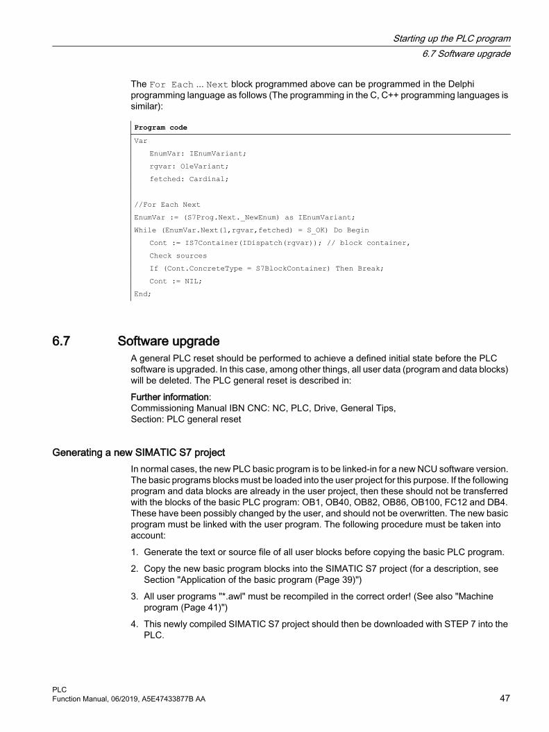
The For Each ... Next block programmed above can be programmed in the Delphi programming language as follows (The programming in the C, C++ programming languages is similar):
Program codeVar EnumVar: IEnumVariant; rgvar: OleVariant; fetched: Cardinal; //For Each NextEnumVar := (S7Prog.Next._NewEnum) as IEnumVariant;While (EnumVar.Next(1,rgvar,fetched) = S_OK) Do Begin Cont := IS7Container(IDispatch(rgvar)); // block container, Check sources If (Cont.ConcreteType = S7BlockContainer) Then Break; Cont := NIL;End;
6.7 Software upgradeA general PLC reset should be performed to achieve a defined initial state before the PLC software is upgraded. In this case, among other things, all user data (program and data blocks) will be deleted. The PLC general reset is described in:
Further information:Commissioning Manual IBN CNC: NC, PLC, Drive, General Tips,Section: PLC general reset
Generating a new SIMATIC S7 projectIn normal cases, the new PLC basic program is to be linked-in for a new NCU software version. The basic programs blocks must be loaded into the user project for this purpose. If the following program and data blocks are already in the user project, then these should not be transferred with the blocks of the basic PLC program: OB1, OB40, OB82, OB86, OB100, FC12 and DB4. These have been possibly changed by the user, and should not be overwritten. The new basic program must be linked with the user program. The following procedure must be taken into account:
1. Generate the text or source file of all user blocks before copying the basic PLC program.
2. Copy the new basic program blocks into the SIMATIC S7 project (for a description, see Section "Application of the basic program (Page 39)")
3. All user programs "*.awl" must be recompiled in the correct order! (See also "Machine program (Page 41)")
4. This newly compiled SIMATIC S7 project should then be downloaded with STEP 7 into the PLC.
Starting up the PLC program6.7 Software upgrade
PLCFunction Manual, 06/2019, A5E47433877B AA 47

However, it is normally sufficient to recompile the organization blocks (OBs) and the instance data blocks of the S7 project. Prior to upgrading, therefore, only the sources for the organization blocks and the instance data blocks are generated.
NC variablesThe latest NC VAR selector can be used for each NC software release (even older versions). The variables can also be selected from the latest list for earlier NC software versions. The data content in DB120 (default DB for variables) does not depend on the software version. This means, variables selected in an older software version need not be reselected when the software is upgraded.
6.8 I/O modules (FM, CP modules)Additional packages for STEP 7 are generally required for more complex I/O modules (FM, CP modules). Support blocks (FC/FB) are provided in these additional packets. The blocks contain specific functions for operating the relevant module. These functions can be parameterized and called in the user program.
Identical numbersIf handling and basic program blocks have identical numbers, the block numbers of the basic program must remain unchanged. The block numbers of the handling blocks must be renamed to free numbers via STEP 7.
Starting up the PLC program6.8 I/O modules (FM, CP modules)
PLC48 Function Manual, 06/2019, A5E47433877B AA

6.9 TroubleshootingThis section describes problems which may occur, their causes and remedies and should be read carefully before hardware is replaced.
Errors, cause/description and remedySerial no.error in‐forma‐tion
Errors Cause/description To correct or avoid errors
1 No connec‐tion via MPI to PLC.
The MPI cable is not plugged in or is defective. Possibly, the STEP 7 software is also not correctly con‐figured for the MPI card.
Test: Create a link with the programmer in the STEP 7 editor by means of con‐nection "Direct_PLC". A number of node addresses must be displayed here. If they do not appear, the MPI ca‐ble is defective/not plugged in.
2 PLC cannot be accessed in spite of PLC general reset.
A system data block SDB 0 has been loaded with a modified MPI address. This has caused an MPI bus conflict due to dual assign‐ment of addresses.
Disconnect all MPI cables to other com‐ponents. Create the link "Direct_PLC" with the programmer. Correct the MPI address.
3 All four LEDs on the PLC flash (DI dis‐aster)
A system error has occurred in the PLC.Measures:The diagnostic buffer on the PLC must be read to analyze the sys‐tem error in detail. To access the buffer, the PLC must be stopped (e.g. set "PLC" switch to position 2). A hardware reset must then be performed. The diagnostic buffer can then be read out with STEP 7. Relay the information from the di‐agnostic buffer to the Hotline / De‐velopment Service. A general re‐set must be carried out if reques‐ted after the hardware RESET. The diagnostic buffer can then be read with the PLC in the Stop state.
Once the PLC program has been RE‐SET or reloaded, the system may re‐turn to normal operation. Even in this case, the content of the diagnostic buf‐fer should be sent to the Development Office.
Starting up the PLC program6.9 Troubleshooting
PLCFunction Manual, 06/2019, A5E47433877B AA 49

Starting up the PLC program6.9 Troubleshooting
PLC50 Function Manual, 06/2019, A5E47433877B AA

Coupling of the PLC CPU 77.1 General information
A CPU of the S7-300 automation system is used as PLC for the SINUMERIK 840D sl. The PLC-CPU is integrated into the NCU component as a sub-module. A reference to the performance data of the PLC CPU can be found in Section "Key data of the PLC CPU (Page 31)".
7.2 Properties of the PLC CPUThe PLC integrated in the SINUMERIK 840D sl generally has the same functionality as the corresponding SIMATIC S7-300 PLC.
For differences, see reference in Section "Key data of the PLC CPU (Page 31)".
Owing to differences in their memory system as compared to a SIMATIC S7-300 PLC, certain functions are not available (e.g. save blocks on memory card, save project on memory card).
Note
As with the PLC integrated in SINUMERIK, there is no automatic start of the PLC after power failure and recovery for a SIMATIC S7-300 PLC when a "PLC stop" is triggered by an operator action on the programming device. For safety reasons, the PLC remains in the stop state with an appropriate diagnostic entry. You can start the PLC only by an operator action on the programming device, "Execute a restart", or via the mode selector "Stop" > "Run" (warm restart).
7.3 Interface with integrated PLC
Physical interfacesWith the SINUMERIK 840D sl, the PLC integrated in the NCU offers the option of exchanging signals between the NC and PLC directly via a dual-port RAM.
Data exchange with the operator panel Data exchange with the operator panel (e.g. TCU/OP) can be performed via Ethernet or PROFIBUS. With a connection via Ethernet, communication takes place via the integrated communication processor (CP 840D sl).
Data exchange with the machine control panel (MCP) and handheld unit (HHU) can be performed via MPI, PROFIBUS or Ethernet.
Programming devices should preferably be connected via Ethernet or via MPI (Multi-Point Interface) directly to the PLC.
PLCFunction Manual, 06/2019, A5E47433877B AA 51

Figure 7-1 NC-PLC coupling on SINUMERIK 840D sl (integrated PLC)
Interface: NC/PLCThe data exchange between NC and PLC is organized by the basic program on the PLC side. The status information, such as "Program running", stored by the NC in the NC/PLC interface is copied to data blocks by the basic program at the beginning of the cycle (OB1) and can then be accessed in the user program (user interface). The control signals for the NC (e.g. NC start) entered in the interface data block by the user are also written to the internal DPR and transferred to the NC at the start of the cycle.
Workpiece-program-specific auxiliary functions transferred to the PLC are first evaluated by the basic program (alarmdriven) and then transferred to the user interface at the start of OB1. If the relevant NC block contains auxiliary functions that require that NC processing is interrupted (e.g. M06 for tool change), the basic program stops the decoding of the NC block initially for one PLC cycle. The user can then use the "read disable" interface signal to halt the block execution until the tool change has been completed. If, on the other hand, the relevant NC block only contains auxiliary functions, which do not require interruption of the decoding (e.g. M08 for
Coupling of the PLC CPU7.3 Interface with integrated PLC
PLC52 Function Manual, 06/2019, A5E47433877B AA

cooling medium on), the transfer of these "fast" auxiliary functions is directly acknowledged in OB40, so that decoding is only insignificantly influenced by the transfer to the PLC.
The evaluation and enabling of the G commands transferred from the NC are also alarm-driven and acknowledged, however they are transferred directly to the user interface. If a G command is evaluated at several points in the PLC program, differences in the information of the G command within one PLC cycle may arise.
In the case of NC actions triggered and assigned with parameters by the PLC (e.g. traverse concurrent axes), triggering and parameter assignment is performed using FCs and FBs, not interface data blocks. The FCs and FBs belonging to the actions are supplied together with the basic program. The FCs and FBs required must be loaded by the user and called in the PLC program of the machine manufacturer (machine program). For an overview of FC, FB and data blocks, sorted according to basic and extended functions, please refer to Section "Start-up of PLC programs".
Interface: HMI/PLC HMI/PLC data exchange is performed via the integrated CP, whereby the HMI is always the active partner (client) and the PLC is always the passive partner (server). Data transferred or requested by the HMI is read from and written to the HMI/PLC interface area by the PLC operating system (timing: Cycle control point). From the viewpoint of the PLC application, the data is identical to I/O signals.
Interface: MCP/PLC or HHU/PLC (connection: Ethernet) MCP/PLC and HHU (HT 2) / PLC data is exchanged via the integrated CP. The CP transfers the MCP/HHU signals to and fetches them from the PLC's internal DPR (Dual-Port RAM). On the PLC side, the basic program handles communication with the user interface. The basic-program parameters (FB1, DB7) define the operand areas (e.g. I/O areas) and the start addresses.
Interface: MCP/PLC (connection: PROFIBUS)MCP/PLC data exchange takes place via the PLC's PROFIBUS. The MCP's I/O addresses are to be placed in the PLC's process image area and via HW configuration in STEP 7. The MCP*In, MCP*Out pointer variables must be set to the same addresses. The selected DP slave number must be entered in MCP*BusAdr.
Interface: HHU/PLC (connection: MPI)The HHU/PLC data exchange is performed via the MPI interface on the PLC. The "Communication with global data (GD)" service is used for this purpose (see also STEP 7 User Manual). The PLC operating system handles the transfer of signals from and to the user interface. The STEP 7 "Communication configuration" configuring tool is used to define both GD parameters as well as operand areas (e.g. I/O areas) and their start addresses.
7.4 Diagnostic buffer on PLCThe diagnostic buffer of the PLC (readable using STEP 7) will enter diagnostic information on the PLC operating system.
Coupling of the PLC CPU7.4 Diagnostic buffer on PLC
PLCFunction Manual, 06/2019, A5E47433877B AA 53

Coupling of the PLC CPU7.4 Diagnostic buffer on PLC
PLC54 Function Manual, 06/2019, A5E47433877B AA

Interface structure 88.1 Interface
Interface DBsMapping in interface DBs is necessary due to the large number of signals exchanged between the NC and PLC. These are global DBs from the viewpoint of the PLC program.
8.2 PLC/NCK interface
General The PLC/NC interface comprises a data interface on one side and a function interface on the other. The data interface contains status and control signals, auxiliary and G commands, while the function interface is used to transfer jobs from the PLC to the NC.
Data interface The data interface is subdivided into the following groups:
● NC-specific signals
● Mode-group-specific signals
● Channel-specific signals
● Axis/spindle/drive-specific signals
PLCFunction Manual, 06/2019, A5E47433877B AA 55

Function interface The function interface is formed by FBs and FCs. The figure below illustrates the general structure of the interface between the PLC and the NC.
Figure 8-1 PLC-NC user interface
Interface structure8.2 PLC/NCK interface
PLC56 Function Manual, 06/2019, A5E47433877B AA
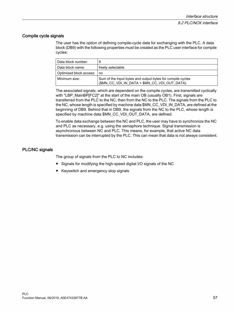
Compile cycle signals The user has the option of defining compile-cycle data for exchanging with the PLC. A data block (DB9) with the following properties must be created as the PLC user interface for compile cycles:
Data block number: 9Data block name: freely selectableOptimized block access: noMinimum size: Sum of the input bytes and output bytes for compile cycles
($MN_CC_VDI_IN_DATA + $MN_CC_VDI_OUT_DATA)
The associated signals, which are dependent on the compile cycles, are transmitted cyclically with "LBP_MainBP[FC2]" at the start of the main OB (usually OB1). First, signals are transferred from the PLC to the NC, then from the NC to the PLC. The signals from the PLC to the NC, whose length is specified by machine data $MN_CC_VDI_IN_DATA, are defined at the beginning of DB9. Behind that in DB9, the signals from the NC to the PLC, whose length is specified by machine data $MN_CC_VDI_OUT_DATA, are defined.
To enable data exchange between the NC and PLC, the user may have to synchronize the NC and PLC as necessary, e.g. using the semaphore technique. Signal transmission is asynchronous between NC and PLC. This means, for example, that active NC data transmission can be interrupted by the PLC. This can mean that data is not always consistent.
PLC/NC signals The group of signals from the PLC to NC includes:
● Signals for modifying the high-speed digital I/O signals of the NC
● Keyswitch and emergency stop signals
Interface structure8.2 PLC/NCK interface
PLCFunction Manual, 06/2019, A5E47433877B AA 57

Figure 8-2 PLC/NC interface
NC/PLC signals The group of signals from the NC to PLC includes:
● Actual values of the digital and analog I/O signals of the NC
● Ready and status signals of the NC
Also stored in this group are the HMI handwheel selection signals and the channel status signals.
The signals for handwheel selection are decoded by the basic program and entered in the machine/axis-specific interface.
Digital/analog inputs/outputs of the NC The following must be noted with respect to the digital and analog inputs and outputs of the NC:
Interface structure8.2 PLC/NCK interface
PLC58 Function Manual, 06/2019, A5E47433877B AA

Inputs:
● All input signals or input values of the NC are also transferred to the PLC.
● The transfer of signals to the NC part program can be suppressed by the PLC. Instead, a signal or value can be specified by the PLC.
● The PLC can also transfer a signal or value to the NC even if there is no hardware for this channel on the NC side.
Outputs:
● All signals or values to be output are also transferred to the PLC.
● The NC can also transfer signals or values to the PLC even if there is no hardware for this channel on the NC side.
● The values transferred by the NC can be overwritten by the PLC.
● Signals and values from the PLC can also be output directly via the NC I/O.
Note
When implementing the digital and analog NC I/O, the information contained in the following documentation must be taken into account:Further informationFunction Manual Basic Functions; Digital and Analog NC I/O
PLC / mode group signals The mode signals set by the machine control panel or the HMI are transferred to the operating mode group of the NC. These apply to all NC channels. Several mode groups can be optionally defined in the NC.
The mode group reports its current status to the PLC.
Figure 8-3 PLC / mode group interface
PLC/NC signals The signal groups below must be considered on the interface:
● Control/status signals
● Auxiliary commands / G commands
Interface structure8.2 PLC/NCK interface
PLCFunction Manual, 06/2019, A5E47433877B AA 59

● Tool management signals
● NC functions
The control/status signals are transferred cyclically at the start of OB1. The signals entered in the channel-specific interface by the HMI (HMI signals are entered by the PLC operating system) are also transferred at this time if they have been defined on the HMI operator panel, not on the MCP.
Auxiliary commands and G commands are entered in the interface data blocks in two ways. First, they are entered with the change signals.
● The M signals M00 - M99 (they are transferred from the NC with extended address 0) are also decoded and the associated interface bits set for the duration of one cycle.
● For G commands, only the groups selected via machine data are entered in the interface data block.
● The S values are also entered together with the related M signals (M03, M04, M05) in the spindle-specific interface. The axis-specific feedrates are also entered in the appropriate axis-specific interface.
When the tool management (magazine management) function is activated in the NC, the assignment of spindle or revolver and the loading/unloading locations are entered in separate interface DBs (DB71-73).
The triggering and parameter assignment of NC functions is performed by means of PLC function calls. The following function calls are available:
● Position a linear axis or rotary axis
● Position an indexing axis
● Start a prepared asynchronous subprogram (ASUP)
● Read/write NC variables
● Update magazine and tool motion
Some of the above functions are described in their own function documentation.
Figure 8-4 PLC/NC channel interface
Interface structure8.2 PLC/NCK interface
PLC60 Function Manual, 06/2019, A5E47433877B AA
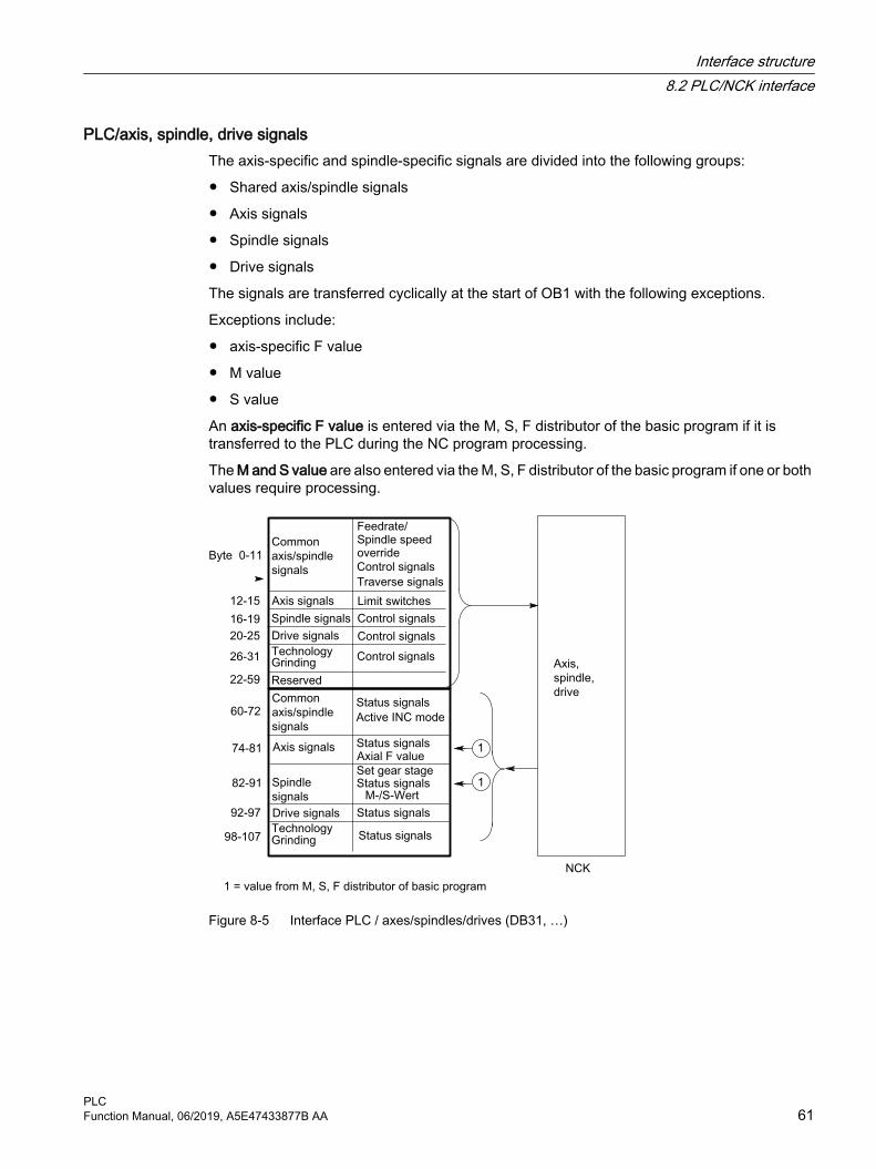
PLC/axis, spindle, drive signals The axis-specific and spindle-specific signals are divided into the following groups:
● Shared axis/spindle signals
● Axis signals
● Spindle signals
● Drive signals
The signals are transferred cyclically at the start of OB1 with the following exceptions.
Exceptions include:
● axis-specific F value
● M value
● S value
An axis-specific F value is entered via the M, S, F distributor of the basic program if it is transferred to the PLC during the NC program processing.
The M and S value are also entered via the M, S, F distributor of the basic program if one or both values require processing.
Figure 8-5 Interface PLC / axes/spindles/drives (DB31, …)
Interface structure8.2 PLC/NCK interface
PLCFunction Manual, 06/2019, A5E47433877B AA 61

8.3 Interface PLC/HMI
General The following groups of functions are required for the PLC/HMI interface:
● Control signals
● Machine operation
● PLC messages
● PLC status display
Control signalsSome control signals are signal inputs, for example, via the machine control panel, which have to be taken into account by the HMI. This group of signals includes, for example, display actual values in MCS or WCS, key disable, etc. These are exchanged with the HMI via a separate interface data block (DB19).
Machine operationAll operator inputs, which lead to response actions on the machine, are monitored by the PLC. Operator actions are usually performed on the machine control panel (MCP). However, it is also possible to perform some operator actions on the HMI, e.g. mode selection.
The PLC operating system enters the operating signals sent by the HMI directly into the interface data blocks. As standard, the basic program routes these operating signals in such a way that, provided equivalent operator actions are available, these can be performed either on the HMI or on the MCP. If required, the user can switch off operation via HMI using an FB1 parameter "MMCToIF".
PLC messages The signaling functions are based on the system diagnostic functions integrated in the operating system of the AS 300. These have the following characteristics:
● The PLC operating system enters all important system states and state transitions in a diagnostics status list. Communication events and I/O module diagnostics data (for modules with diagnostic functions) are also entered.
● Diagnostics events, which lead to a system stop, are also entered with a time stamp in a diagnostic buffer (circular buffer) in the chronological order of their occurrence.
● The events entered in the diagnostic buffer are automatically transmitted to human machine interface systems (OP or HMI) via the bus systems once these have issued a ready signal (message service). "Transfer to the node ready" is a function of the PLC operating system. Receipt and interpretation of the messages are executed by the HMI software.
● The PLC user program can also use SFCs (System Function Calls) to enter messages in the diagnostic buffer or ALARM S/ALARM SQ buffer.
● The events are entered in the alarm buffer.The associated message texts must be stored on the OP or HMI.
Interface structure8.3 Interface PLC/HMI
PLC62 Function Manual, 06/2019, A5E47433877B AA

An FC (FC10) for message acquisition is prepared in conjunction with the basic program. This FC records events, subdivides them into signal groups and reports them to the HMI via the alarm buffer.
The message acquisition structure is shown in the figure "Acquisition and signaling of PLC events". The features include:
● Bit fields for events related to the NC/PLC interface are combined in a single data block (DB2) with bit fields for user messages.
● Bit fields are evaluated at several levels by FC10.
– Evaluation 1; acquisition of group signalsA group signal is generated for each group of signals if at least one bit signal is set to "1". This signal is generally linked to the disable signal of the NC/PLC interface (on modules with diagnostic functions). The group signals are acquired completely in cycles.
– Evaluation 2; acquisition of alarm messagesA fixed specification exists to define which signals in a group generate an alarm message when they change from "0" to "1".
– Evaluation 3; acquisition of operating signalsA fixed specification exists to define which signals in a group generate an operational message.
● The scope of the user bit fields (user area) is set by default to 10 areas with 8 bytes each, but the number of areas can also be adjusted to suit the requirements of the machine manufacturer via basic program parameters in FB1.
Acknowledgement conceptThe following acknowledgement procedures are implemented for error and operational messages:
Operating messages are intended for the display of normal operating states as information for the user. Acknowledgement signals are, therefore, not required for this type of message. An entry is made in the diagnostic status list for incoming and outgoing messages. The HMI maintains an up-to-date log of existing operating messages using the identifiers "operating message arrived" and "operating message gone".
Alarm messages display error states on the machine, which will usually lead to the machine being stopped. Where several errors occur in rapid succession, it is important to be able to distinguish their order of occurrence for troubleshooting purposes. This is indicated, on the one hand, by the order in which they are entered in the diagnostic buffer and on the other, by the time stamp, which is assigned to every entry.
If the cause of the error disappears, the associated alarm message is only deleted if the user has acknowledged it (e.g. by pressing a key on the MCP). In response to this signal, the "Message acquisition" FC examines which of the reported errors have disappeared and enters these in the diagnostic buffer with the entry "Alarm gone". This enables the HMI to also maintain an up-to-date log of pending alarm messages. The time of day indicating the time at which the error occurred is maintained for messages, which are still pending (in contrast to a received interrogation).
Interface structure8.3 Interface PLC/HMI
PLCFunction Manual, 06/2019, A5E47433877B AA 63

STEP 7A tool can be started in the SIMATIC Manager via menu item "Target system" > "CPU messages". Alarms and messages can be displayed by number using this tool. To do this, acivate the "Alarm" tab and enter a check mark under "A" in the upper half of the screen.
User programThe user PLC program only has to call the basic program block FC10 with appropriate parameter settings in the cyclic program section and set or reset the bit fields in DB2. Everything else is handled by the basic program and the HMI.
Figure 8-6 Acquisition and signaling of PLC events
Extensions of the PLC alarms via block FC10The FB1 parameter "ExtendAlMsg" selects the PLC alarm mechanism.
If "ExtendAlMsg:= FALSE" the earlier process of the FC10 with the DB2 is active as bit array data block. The known restrictions regarding the number of channels and axes are applicable.
On the other hand, in case of "ExtendAlMsg:= TRUE" the extension of the FC10 becomes active. DB2 and DB3 are created just as before. The user must set or reset the bits in DB2. The parameter setting via message and alarm and a parameter setting of the numeric value of the 2nd decade of the user alarms are contained in DB5.
Interface structure8.3 Interface PLC/HMI
PLC64 Function Manual, 06/2019, A5E47433877B AA

The extensions are:
● Support for 10 channels, 31 axes, 64 user areas (the number of user areas should be entered in the FB1 parameter "MsgUser").
● Areas for feed stop, read-in disable, etc. are available without messages. The information from this area is stored on the interface in DB21, DB31 depending on FC10 parameter "ToUserIF" together with the related message bits as group signals. As such, the previous cumbersome handling of the signals is omitted.
● The alarms / messages also get the 16-bit integer additional value (%Z parameter in the alarm text) in addition to the alarm number for the user area 0. The user must write the 16-bit integer values in the DB2 in the array variable ZInfo0 parallel to setting an alarm bit. An integer value is available for each bit in the user area 0, see UDT1002 in the basic program.
● The user messages can be parameteized in the second decade of the message number in the numerical range 0 to 9. The display value of the second decade must be written by the user in the DB5 in the array variable UserDek2No. A number can be defined for each user area, see DB5 in the basic program.The value 0 is set by default for the second decade.
The structuring of the DB2 in UDT1002 can be recognized (basic program). In case of new alarm functions, the UDT1002 must be assigned symbolically to the DB2.
At the start of DB2 there are bit arrays for signals without alarm generation. This is followed by an array of size 64 integer values for additional info about the user area 0.
Thereafter follow the areas, which also trigger alams / messages (see List manual) These areas are extended to 10 channels, 31 axes.
Switching over a user program from the small DB2 layout to the large DB2 layout (UDT2 → UDT1002)With the small DB2 layout, i.e. if DB2 is derived from UDT2 - and FB1 parameter "ExtendAlMsg = FALSE" is used - then a max. of 8 channel areas, max. of 18 axis areas and a max. of 31 user areas (depending on FB1 parameter "MsgUser") can be used. As default setting, 10 user areas are defined in the UDT2. When using more than 10 user areas (FB1 parameter "MsgUser" > 10), then users must extend UDT2 if DB2 is to be symbolically accessed.
With the large DB2 layout, i.e. if DB2 is derived from UDT1002 - and FB1 parameter "ExtendAlMsg = TRUE" is used - then you can generate alarms for 10 channels, 31 axes and 64 user areas.
If it is no longer possible to generate alarms with the restrictions of the small DB2 layout, then it may be necessary to switch over an already existing project to the large layout. The switchover procedure depends on how DB2 is accessed in the project. The various procedures are described in the following.
Switchover for symbolic programmingThe source container of the basic program contains the "udt2_for_Convert.awl" file, which contains the following structural element from UDT1002:
● ChanA as array of 1 ... 8 for switching over the 8 channel ranges.
● AxisA as array of 1 ... 18 for switching over the 18 axis/spindle ranges
● UserA as array from 0 ... 31 for switching over user areas
Interface structure8.3 Interface PLC/HMI
PLCFunction Manual, 06/2019, A5E47433877B AA 65

From this STL file, a UDT can be generated that assigns the offsets of the small DB2 version to the symbolic names of the large DB2 version.
Table 8-1 Symbolic signal designator from the channel area
DB2 without alarm extension DB2 with alarm extensionCj.FDD_5j00xx[i] ChanA[j].FDD_5C00xx[i]Cj.FDD_RID_5j01xx[i] ChanA[j].FDD_RID_5C01xx[i]Cj.RID_5j02xx[i] ChanA[j].RID_5C02xx[i]Cj.NCSD_5j03xx[i] ChanA[j].NCSD_5C03xx[i]Cj.FdStop_1_5j11xx[i] ChanA[j].FdStop_1_5C11xx[i]Cj.FdStop_2_5j12xx[i] ChanA[j].FdStop_2_5C12xx[i]Cj.FdStop_3_5j13xx[i] ChanA[j].FdStop_3_5C13xx[i]
j (shown bold): Channel number (1 … 8)
Table 8-2 Symbolic signal designator from the axis/spindle area
DB2 without alarm extension DB2 with alarm extension_jFdStop600jxx[i] AxisA[j].AAFdStop60AAxx[i]_jjFdStop60jjxx[i] AxisA[jj].AAFdStop60AAxx[i]
j or jj (shown bold): Axis/spindle number (1 ... 9 or 10 … 18)
Table 8-3 Symbolic signal designator from the user area
DB2 without alarm extension DB2 with alarm extensionA70jjxx[i] UserA[jj].A70UUxx[i]
jj (shown bold): User range (00 … 31)
Procedure:
1. Select the block folder and under "Object properties" > "Operand priority" ensure that "Absolute value has priority" is active.
2. Compile source "udt2_for_Convert.awl".The new symbols of the large layout are now already available in UDT2.
3. Generate sources of blocks, which contain symbolic assignments to the DB2. To do this, in the LAD/STL/FBD KOP/AWL/FUP editor, under "File" > "Generate source", select the required blocks and create an STL source.
4. In the symbol table, assign UDT1002 to the DB2.
5. In the SIMATIC Manager under "Sources" compile the currently generated source.
Now all the alarm allocations are assigned to the new data areas in the DB2 and now only the parameter "ExtendAlMsg" at FB1 must be set to True.
Switchover for direct absolute access to the DB2For instance, this is the case if the user first opens the DB2 in the program code, and then directly accesses it (at "ALMSG_DB"; S DBX180.0;).
Interface structure8.3 Interface PLC/HMI
PLC66 Function Manual, 06/2019, A5E47433877B AA

Procedure:
1. Using the cross reference list (menu command "Tools" > "Reference data" > "Display"), search for blocks in the user program that's contain DB2 access operations.
2. Open the program locations involved one after the other and switchover the offset addresses of the relevant DB2 signals.The new offset address results from the sum of the previous address and the "offset".
NoteSearching for DB2 accesses in the user program
Not all DB2 access operations are found via the reference data. Accesses via BLK_DB or pointer are not detected.
A comparison of the particular offset addresses and/or the address offset are listed in the following table.
Table 8-4 Addresses in the DB2 versions
Alarm number
DB2 without alarm extension Off‐set
DB2 with alarm extensionArea Offset Offset Area
- 0
Chan(Channel 1 ... 10)
- 120
Axis(Axis/spindle 1 ... 31)
Addition‐al value
182
As of V6.0: AddVa‐lUserA0 (AddValU‐serA0 0 ... 63)(Up to V4.8: ZInfo0 0 ... 63)
5C0000 ... 5C1315
(C1 ... C8)Channel 1 ... 8
Byte 0 ... <last byte for channel area>
310 Byte 310 ... <last byte for channel area>
ChanAChannel 1 ... 10
60AA00 ... 60AA15
(Axis areas)Axis/spindle1 ... 18
Byte 144 ... <last byte for axis area>
346 Byte 490 ... <last byte for axis area>
AxisAAxis/spindle 1 ... 31
70UU00 ... 70UU63
(User area)User area0 ... 31
Byte 180 ... <last byte for user area>
374 Byte 554 ... <last byte for user area>
UserAUser area 0 ... 63
Conversion for indirect access via BLKMOVThe following adaptations are required if DB2 is not directly accessed, but instead BLKMOV is used, for example to copy memory areas of its own data blocks to DB2.
Within the individual DB2 areas, the offset addresses of both DB2 versions are offset by a specific value. This offset is, however, different for each DB2 area.
Interface structure8.3 Interface PLC/HMI
PLCFunction Manual, 06/2019, A5E47433877B AA 67

A check has to be made whether BLKMOV copy operations are used that copy a memory area that is larger than a DB2 area. If this is the case, then copying must be split up over several operations. The new offset address must then be considered and adapted depending on the particular DB2 area.
8.4 PLC/MCP/HHU interface
General There are different connection options for the machine control panel (MCP) and the handheld unit (HHU). This is in part due to the history of the MCP and HHU. This description focuses primarily on the connection of the Ethernet components.
On the SINUMERIK 840D sl, the machine control panel (MCP) and handheld unit (HHU) are connected via the Ethernet bus, which also links the TCU to the NCU. The advantage of this is that only one bus cable is required to connect the operating unit.
Topology SINUMERIK 840D slOn the 840 D, the machine control panel and the handheld unit are connected to the CP 840D sl Ethernet bus (see Figure below). Where the connection of further keys and displays is required for customized operator panels, an additional keyboard interface (machine control panel without operating unit) can be used. For each keyboard interface, 64 pushbuttons, switches, etc. and 64 display elements can be connected via ribbon cable.
The signals sent from the MCP are copied to the PLC's DPR (Dual-Port RAM) by the integrated Ethernet CP-840D sl. The basic program of the PLC enters the incoming signals in the input image configured at FB1. The NC-related signals are generally distributed by the basic program to the NC/PLC interface. If required, the signals can be modified by the user.
The signals from the PLC to the MCP (displays) are transferred in the opposite direction.
Interface structure8.4 PLC/MCP/HHU interface
PLC68 Function Manual, 06/2019, A5E47433877B AA

Figure 8-7 Connection of the machine control panel on 840D sl
Bus addressesOn Ethernet components, MAC and IP addresses or logic names are determining factors in respect of communication. The control system's system programs convert logic names into MAC or IP addresses. On the PLC, the numeric component of the logic name is used for communication. This numeric part is specified by the user to the FB1 using parameter "MCPxBusAdr".
The logical name of an MCP or HHU always begins with "DIP". This is followed by a number corresponding to the switch position of the MCP component (e.g. DIP192, DIP17).
MCP interface in the PLCThe signals from the machine control panel are routed by default via the I/O interface to the PLC area. A distinction must be made between NC and machine-specific signals. NC-specific key signals are distributed to the relevant mode-group-, NC-, axis- and spindle-specific interface by FC19 (or FC24, FC25, FC26, depending on the type of MCP) by default. The reverse applies to the associated status signals which are routed to the MCP interface. For this purpose, FC19 or the other blocks mentioned above must be called in the user program.
Customized keys, which can be used to trigger a wide range of machine functions, must be evaluated directly by the user program. The user program also routes the status signals to the output area for the LEDs.
Interface structure8.4 PLC/MCP/HHU interface
PLCFunction Manual, 06/2019, A5E47433877B AA 69

Figure 8-8 Interface to and from machine control panel
Interface structure8.4 PLC/MCP/HHU interface
PLC70 Function Manual, 06/2019, A5E47433877B AA
Structure and functions of the basic program 9General
The PLC program has a modular structure. The organization blocks (OB) form the interface between the operating system and the basic and user programs.
● Restart (warm restart) with start-up and synchronization (OB100)
● Cyclic operation (OB1)
● Process alarms (OB40)
● Asynchronous errors: Diagnostics alarm (OB82), module failure (OB86)
The calls of the function blocks of the basic and user programs must be programmed by the user in the organization blocks (OB).
PLCFunction Manual, 06/2019, A5E47433877B AA 71

Figure 9-1 Structure of the basic program (principle)
Structure and functions of the basic program
PLC72 Function Manual, 06/2019, A5E47433877B AA

9.1 Startup and synchronization of NCK PLC
Loading the basic program The basic program must be loaded with the S7 tool when the PLC is in the Stop state. This ensures that all blocks in the basic program will be initiated correctly the next time they are called. Otherwise, undefined states can occur in the PLC (e.g. blinking of all PLC LEDs).
Startup,The synchronization of NC and PLC is performed during start-up. The system and user data blocks are checked for integrity and the most important basic program parameters are verified for plausibility. In cases of errors, the basic program produces an alarm (visible on HMI) and switches the PLC to the Stop state.
A warm restart is not provided, i.e. following system initialization, the operating system runs organization block OB100 and always commences cyclic execution at the start of OB1.
SynchronizationThe PLC is synchronized with the HMI, NC and CP during power-up.
Sign-of-lifeAfter a correct initial start and the first complete OB1 cycle (basic setting cycle) the PLC and NC continuously exchange sign-of-life signals. If the sign of life from the NC fails to materialize, the PLC/NC interface is initialized and the signal "NC CPU ready" in DB10 is set to FALSE.
9.2 Cyclic operation (OB1)
General The NC/PLC interface is processed completely in cyclic mode. From a chronological viewpoint, the basic program runs ahead of the user program. In order to minimize the execution time of the basic program, only the control/status signals are transferred cyclically; transfer of the auxiliary commands and G commands takes place only on request.
The following functions are performed in the cyclic part of the basic program:
● Transmission of the control/status signals
● Distribution of the auxiliary functions
● M decoding (M00 - M99),
● M, S, F distribution
● Transfer the MCP signals via NC
● Acquisition and conditioning of the user errors and operational messages.
Structure and functions of the basic program9.2 Cyclic operation (OB1)
PLCFunction Manual, 06/2019, A5E47433877B AA 73

Control/status signalsA shared feature of the control and status signals is that they are bit fields. The basic program updates them at the start of OB1.
The signals can be subdivided into the following groups:
● General signals
● Mode-group-specific signals (such as modes)
● Channel-specific signals (such as program and feed modifications)
● Axis- and spindle-specific signals (such as feed disable)
Auxiliary and G commandsThe auxiliary and G commands have the following characteristics:
● Transfer to the PLC is block-synchronous (referred to a part program block)
● Transfer is acknowledge-driven.
● The acknowledgment times have an immediate effect on the execution time of NC blocks containing auxiliary functions requiring acknowledgment.
The value range is presented in the table below:
Function Structure Value range Data type 1st value 2nd value 1st value 2nd value 1st value 2nd valueG command G command 2551) ByteM word M group M word 99 99.999.999 Word DWordS word Spindle no. S word 6 Floating
point2)Word DWord
T word Magazine no.
T word 99 65535 Word Word
D word - D word 99 255 Byte ByteH word H group H word 99 Floating
pointWord DWord
F word Axis no. F word 18 Floating point
Word DWord
1) relative number, transferred for each G group2) corresponding STEP 7 format (24-bit mantissa, 8-bit exponent)
The M, S, T, H, D and F values sent by the NC are output together with the accompanying change signals to the CHANNEL DB interface via the auxiliary/G command distributor (see List Manual). The two values of the auxiliary function are transferred to the appropriate data word. The accompanying change signal is activated to 1 for one PLC cycle. When the change signal is reset, the acknowledgment is passed to the NC. The acknowledgment of high-speed auxiliary functions is performed when the basic program detects the auxiliary function.
In addition to distribution of the auxiliary and G commands, selected signals are processed as described below.
Structure and functions of the basic program9.2 Cyclic operation (OB1)
PLC74 Function Manual, 06/2019, A5E47433877B AA
M decoderM functions can be used to transfer switching commands and fixed-point values. Decoded dynamic signals are output to the CHANNEL DB interface for standard M functions (range M00 - M99) (signal duration = 1 cycle time).
G group decodersIn the case of G commands sent by the NC, the related groups are decoded and the current G number is entered in the corresponding interface byte of the CHANNEL DB, i.e. all active G commands are entered in the channel DBs. The entered G commands are retained even after the NC program has terminated or aborted.
Note
During system start-up, all G group bytes are initialized with the value "0".
M, S, F distributorThe M, S, F, distributor is used to enter spindle-specific M words M(1...6)=[3,4,5], S words and F words for axial feeds in the appropriate spindle and axis data blocks. The criterion for distribution is the extended address which is passed to the PLC for M words, S words and axial F words.
MCP signal transmissionDepending on the bus connection, the MCP signals are either transferred directly to the PLC or indirectly to the parameterized I/O areas via an internal procedure using the basic program.
User messagesThe acquisition and processing of the user error messages and operational messages is performed by an FC in the basic program.
9.3 Time-interrupt processing (OB35)The user must program OB35 for time-interrupt processing. The default time base setting of OB 35 is 100 ms. A different time base can be selected using the STEP7 "HW Config" tools. However, the OB35 time setting must be at least 3 ms in order to avoid a PLC CPU stop. The stop is caused by reading of the HMI system state list during powerup of the HMI. This reading process blocks priority class control for approx. 2 ms. The OB35 with a time base set to a rather lower value is then no longer processed correctly.
Structure and functions of the basic program9.3 Time-interrupt processing (OB35)
PLCFunction Manual, 06/2019, A5E47433877B AA 75

9.4 Process-interrupt processing (OB 40) A process interrupt OB40 (interrupt) can, for example, be triggered by appropriately configured I/Os or by certain NC functions. Due to the different origin of the interrupt, the PLC user program must first interpret the cause of the interrupt in OB40. The cause of the interrupt is contained in the local data of OB40.
Further informationSIMATIC STEP 7 Description or Online Help of STEP 7
9.5 Diagnostic alarm, module failure processing (OB82, OB86)
GeneralIn the event of a diagnostic alarm or failure of an I/O module, basic program block OB82 or OB86 is called. The basic program block FC5 "Diagnostic alarm and module failure" is called from these blocks.
Bus diagnostics The status of the DP slave modules at PROFIBUS connections MPI/DP, DP1 - or the PROFINET connection PN - is signaled to the user program by the basic program using the "Slaves OK" group signal of the particular bus system:
● DB10.DBX92.0 == 1 (MPI/DP bus: Slaves OK)
● DB10.DBX92.1 == 1 (DP1 bus: Slaves OK)
● DB10.DBX92.2 == 1 (PN bus: Slaves OK)
The group signal is derived from the LED status of the respective bus system (system state list SZL 0x174).
Alarm outputIf an error or a failure of a slave is detected at the particular bus system, the following alarm is displayed:
● Alarm 400551 (MPI/DP bus)
● Alarm 400552 (DP1 bus)
● Alarm 400553 (PN bus)
The alarm is automatically deleted again when the error is removed.
Suppression of the alarm output 400551, 400552, 400553By setting one of the following signals, the alarm is suppressed for the particular bus system:
● DB10.DBX92.4 = 1 (suppress alarm 400551)
● DB10.DBX92.5 = 1 (suppress alarm 400552)
● DB10.DBX92.6 = 1 (suppress alarm 400553)
Structure and functions of the basic program9.5 Diagnostic alarm, module failure processing (OB82, OB86)
PLC76 Function Manual, 06/2019, A5E47433877B AA
The alarm is immediately suppressed as soon as the signal is set. Before the fault occurs or while a fault is already active.
When the signal is reset, in the case of a fault, the corresponding alarm is displayed.
The signals are reset when the control system powers up.
Note
By setting the signal, the fault monitoring for the complete bus line is deactivated!
9.6 Response to NCK failure
General During cyclic operation, the PLC continuously monitors NC availability by querying the sign-of-life. If the NC is no longer reacting, the NC/PLC interface is initialized, and the NC-CPU ready signal in the area of the signals from NC (DB 10.DBX 104.7) is reset. Furthermore, the signals sent from the NC to the PLC and vice versa are set to an initial state.
The PLC itself remains active so that it can continue to control machine functions. However, it remains the responsibility of the user program to set the machine to a safe state.
NC → PLC signalsThe signals sent by the NC to the PLC are divided into the following groups:
● Status signals from the NC, channels, axes and spindles
● Modification signals of the auxiliary functions
● Values of the auxiliary functions
● Values of the G commands
Status signals:
The status signals from the NC, channels, axes, and spindles are reset.
Auxiliary function change signals:
Auxiliary function change signals are also reset.
Auxiliary function values:
Auxiliary function values are retained so that it is possible to trace the last functions triggered by the NC.
G command values:
G command values are reset (i.e. each initialized with the value 0).
Structure and functions of the basic program9.6 Response to NCK failure
PLCFunction Manual, 06/2019, A5E47433877B AA 77

PLC → NC signalsThe signals sent by the PLC to the NC are divided into control signals and tasks that are transferred by FCs to the NC.
Control signals:
The control signals from the PLC to the NC are frozen; cyclic updating by the PLC basic program is suspended.
Jobs from PLC to NC:
The FCs and FBs, which are used to pass jobs to the NC, must no longer be processed by the PLC user program, as this could lead to incorrect checkback signals. During power-up of the control, a job (e.g. read NC data) must not be activated in the user program until the NC-CPU ready signal is set.
9.7 Functions of the basic program called from the user program
GeneralIn addition to the modules of the basic program, which are called at the start of OB1, OB40 and OB100, functions are also provided which have to be called and supplied with parameters at a suitable point in the user program.
These functions can be used, for example, to pass the following jobs from the PLC to the NC:
● Traversing concurrent axes (FC18)
● Start asynchronous subprograms (ASUPs) (FC9),
● Select NC programs (FB4)
Structure and functions of the basic program9.7 Functions of the basic program called from the user program
PLC78 Function Manual, 06/2019, A5E47433877B AA
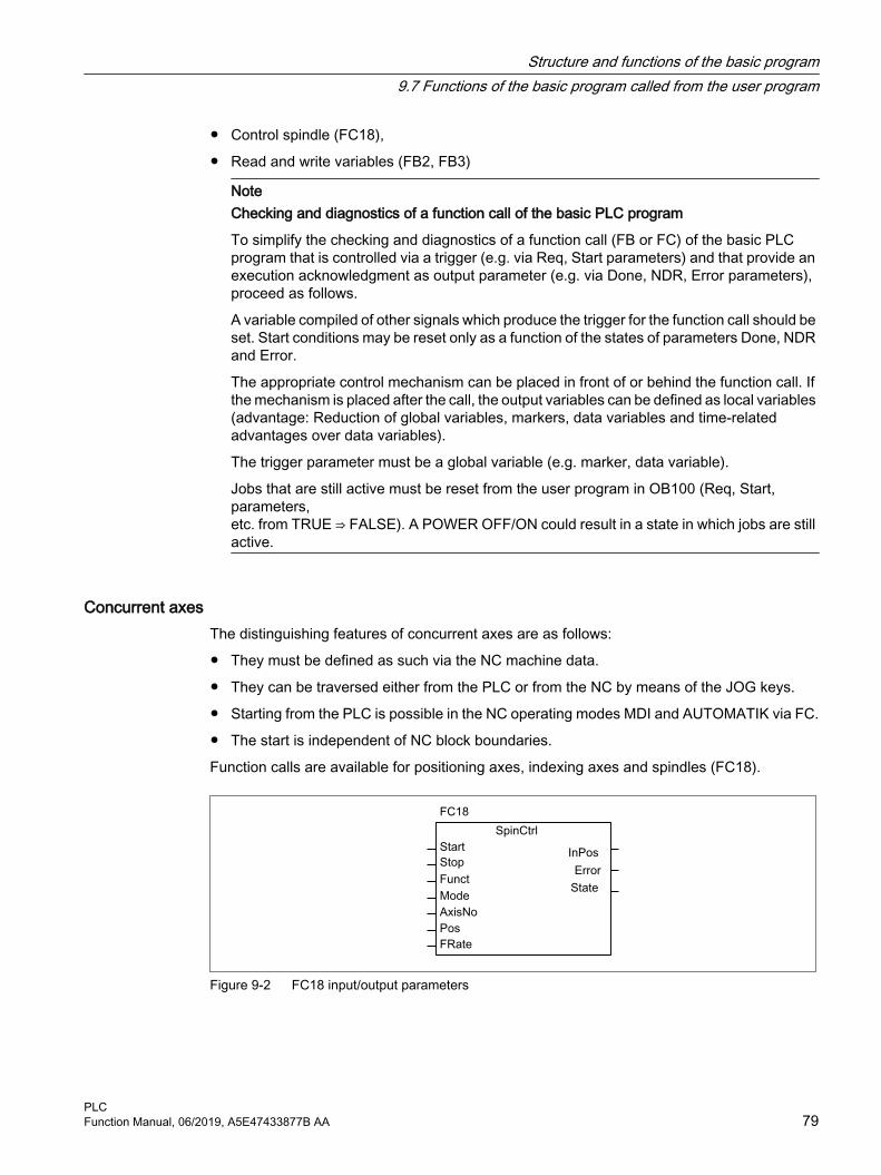
● Control spindle (FC18),
● Read and write variables (FB2, FB3)
NoteChecking and diagnostics of a function call of the basic PLC program
To simplify the checking and diagnostics of a function call (FB or FC) of the basic PLC program that is controlled via a trigger (e.g. via Req, Start parameters) and that provide an execution acknowledgment as output parameter (e.g. via Done, NDR, Error parameters), proceed as follows.
A variable compiled of other signals which produce the trigger for the function call should be set. Start conditions may be reset only as a function of the states of parameters Done, NDR and Error.
The appropriate control mechanism can be placed in front of or behind the function call. If the mechanism is placed after the call, the output variables can be defined as local variables (advantage: Reduction of global variables, markers, data variables and time-related advantages over data variables).
The trigger parameter must be a global variable (e.g. marker, data variable).
Jobs that are still active must be reset from the user program in OB100 (Req, Start, parameters,etc. from TRUE ⇒ FALSE). A POWER OFF/ON could result in a state in which jobs are still active.
Concurrent axes The distinguishing features of concurrent axes are as follows:
● They must be defined as such via the NC machine data.
● They can be traversed either from the PLC or from the NC by means of the JOG keys.
● Starting from the PLC is possible in the NC operating modes MDI and AUTOMATIK via FC.
● The start is independent of NC block boundaries.
Function calls are available for positioning axes, indexing axes and spindles (FC18).
Figure 9-2 FC18 input/output parameters
Structure and functions of the basic program9.7 Functions of the basic program called from the user program
PLCFunction Manual, 06/2019, A5E47433877B AA 79

Asynchronous subprograms (ASUPs)The ASUP can be used to trigger any functions in the NC. Before an asynchronous subprogram can be started from the PLC, it must be ensured that it is available and prepared by the NC program or by FB4 PI services (ASUP).
Once prepared in this way, it can be started at any time from the PLC. The NC program running in one of the parameterized channels of FC9 is interrupted by the asynchronous subprogram. An ASUP is started by calling FC9 from the user program by setting the start parameter to 1.
Note
If an asynchronous subprogram has not been prepared by an NC program or by FB4 (ASUP) (e.g. if no interrupt no. has been assigned), a start error is output (StartErr = TRUE).
Read/Write NC variables NC variables can be read with FB GET while values can be entered in NC variables with FB PUT. The NC variables are addressed via identifiers at inputs Addr1 to Addr8. The identifiers (symbols) point to address data which must be stored in a global DB. To allow generation of this DB, a PC software (NC-Var-Selector) is supplied with the basic program with which the required variables can be selected from a table, which is also supplied. The selected variables are first collected in a second, project-related list. Command Generate DB creates a "*.AWL" file which must be linked to the program file for the machine concerned and compiled together with the machine program.
1 to 8 values can be read or written with a read or write job. If necessary, the values are converted [e.g. NC floating-point values (64-bit) are converted to PLC format (32-bit with 24-bit mantissa and 8-bit exponent) and vice versa]. A loss of accuracy results from the conversion from 64-bit to 32-bit REAL. The maximum precision of 32-bit REAL numbers is approximately 10 to the power of 7.
Structure and functions of the basic program9.7 Functions of the basic program called from the user program
PLC80 Function Manual, 06/2019, A5E47433877B AA

AG_SEND/AG_RECV functions The AG_SEND/AG_RECV functions correspond to the functions of the library "SIMATIC_NET_CP" of the S7-300 CPU in STEP 7. Generally, the online help is valid for these functions. The AG_SEND/AG_RECV functions can be used for data exchange with another station via the integrated "CP 840D sl". A description of the functions is provided in Section "Block descriptions (Page 149)".
Note
Other communication blocks (e.g. BSEND, USEND) which possess a CP343-1 are not supported in SINUMERIK 840D sl.
9.8 Symbolic programming of user program with interface DB
General
Note
The basic program library on the CD supplied with the Toolbox for the 840D contains files NST_UDTB.AWL and TM_UDTB.AWL.
The compiled UDT blocks from these two files are stored in the CPU program of the basic program.
A UDT is a data type defined by the user that can, for example, be assigned to a data block generated in the CPU.
Symbolic names of virtually all the interface signals are defined in these UDT blocks.
The UDT numbers 2, 10, 11, 19, 21, 31, 71, 72, 73, 77, 1002, 1071, 1072, 1073 are used.
Structure and functions of the basic program9.8 Symbolic programming of user program with interface DB
PLCFunction Manual, 06/2019, A5E47433877B AA 81

The assignments have been made as follows:
UDT assignmentsUDT number Assignment to interface DB MeaningUDT2 DB2 Alarms/messagesUDT10 DB10 NCK signalsUDT11 DB11 Mode group signalsUDT19 DB19 HMI signalsUDT21 DB21 to DB30 Channel signalUDT31 DB31 to 61 Axis/spindle signalsUDT71 DB71 Tool management: Load/unload locationsUDT72 DB72 Tool management: Change in spindleUDT73 DB73 Tool management: Change in revolverUDT77 DB77 MCP and HHU signals with standard SDB 210UDT1002 DB2 Extended alarms / messages (FB1 parameter "Ex‐
tendAlMsg:=TRUE")UDT 1071 DB 1071 Tool management: Loading/unloading points (mul‐
titool)UDT 1072 DB 1072 Tool management: Change in spindle (multitool)UDT 1073 DB 1073 Tool management: Change in turret (multitool)
To symbolically program the interface signals, the interface data blocks must first be symbolically assigned using the symbol editor.
For example, symbol "AxisX" is assigned to operand DB31 with data type UDT31 in the symbol file.
After this input, the STEP 7 program can be programmed in symbols for this interface.
Note
Programs generated with an earlier software version that utilize the interface DBs described above can also be converted into symbol programs. A fully qualified command for data access e.g. "U DB31.DBX60.0" (spindle / rotary axis) is necessary in the program previously created. This command is converted upon activation of the symbolics in the editor "AxisX.E_SpKA".
DescriptionAbbreviated symbolic names of the interface signals are defined in the two STL files NST_UDTB.AWL and TM_UDTB.AWL.
In order to create the reference to the names of the interface signals, the name is included in the comment after each signal.
The names are based on the English language. The comments are in English.
Structure and functions of the basic program9.8 Symbolic programming of user program with interface DB
PLC82 Function Manual, 06/2019, A5E47433877B AA

The symbolic names, commands and absolute addresses can be viewed by means of a STEP 7 editor command when the UDT block is opened.
Note
Unused bits and bytes are listed, for example, with the designation "f56_3".● "56": Byte address of the relevant data block● "3": Bit number in this byte
9.9 M decoding acc. to list
Function descriptionUp to 256 M functions with extended address can be decoded from the basic program using the "M decoding according to list" function. The function is activated using FB1 parameter "ListMDecGrp" (number of M groups for decoding). The assignment of the M function with extended address and a signal in the signal list is defined in the decoding list. The signals are also grouped for this purpose.
Decoding list (DB75)The source file for the decoding list (MDECLIST.AWL) is supplied with the basic program. Data block DB75 is created when the STL source is compiled. Before the function is activated, the decoding list (DB75) must be transferred to the PLC followed by a restart.
An M function is decoded if it is in the decoding list. When decoding the M function, the corresponding signal is set in the signal list as a function of the specific group. When setting a signal in the signal list, the interface signal "Read in inhibit" is set by the basic program in the associated channel of the NC. The interface signal is reset again for the channel as soon as the user resets all of the signals output from this channel in the signal list; i.e. after they have been acknowledged.
Signal list (DB76)When activating the function in data block DB76, the basic program creates the signal list. From then, for each M signal decoded according to the list, a signal is set in the signal list (DB76) in the corresponding group. At the same time, the "Readin inhibit" interface signal is set in the channel in which the M function has been output. The interface signal is reset again for the channel as soon as the user resets all of the signals output from this channel in the signal list; i.e. after they have been acknowledged.
Highspeed auxiliary functionsWhen an M function contained in the decoding list is output as "fast help function", no read-in inhibit is set for the corresponding channel of the NC.
The figure below shows the structure of the M decoding according to list:
Structure and functions of the basic program9.9 M decoding acc. to list
PLCFunction Manual, 06/2019, A5E47433877B AA 83

Figure 9-3 M decoding acc. to list
ActivationM decoding is activated using FB1 parameter "ListMDecGrp"
The number of M groups to the evaluated and/or decoded is specified using the appropriate parameter. The function is active for a parameter value = 1 ... 16.
● Basic program, OB100, FB1 parameter ListMDecGrp = <number of M groups> (also see " FB1: RUN_UP - basic program, start section (Page 149) ").
Properties and structure of the decoding list (DB75)Properties of the decoding list (DB75):
● There is only one decoding list independent of the channel.
● The decoding list can include a maximum of 16 groups.
● A group has a maximum of 16 signals
Structure and functions of the basic program9.9 M decoding acc. to list
PLC84 Function Manual, 06/2019, A5E47433877B AA

● There must be an entry in the decoding list for every group of M functions to be decoded.
● The assignment between the M function with extended address and the signal to be set in the signal list is specified in the decoding list using the first and last M function of the associated group.
– First M function: Parameter: "MFirstAdr" ≙ signal or bit 0
– Last M function: Parameter: "MLastAdr" ≙ dependent on the difference to the first M function maximum signal or bit 15
Structure of the decoding list (DB75):
An entry in the decoding lists consists of 3 parameters, each of which is assigned to a group.
Group Extended M address First M address of the group Last M address of the group1 MSigGrp[1].MExtAdr MSigGrp[1].MFirstAdr MSigGrp[1].MLastAdr2 MSigGrp[2].MExtAdr MSigGrp[2].MFirstAdr MSigGrp[2].MLastAdr... ... ... ...16 MSigGrp[16].MExtAdr MSigGrp[16].MFirstAdr MSigGrp[16].MLastAdr
Type and value range of the signals:
Signal Type Value range MeaningMExtAdr INT 0 ... 99 Extended M addressMFirstAdr DINT 0 to 99.999.999 First M address in groupMLastAdr DINT 0 to 99.999.999 Last M address in group
Properties of the signal list (DB76)The signal list (DB76) has the following properties:
● There is only one signal list independent of the channel.
● The signal list can include a maximum of 16 signals for each M group.
Example3 groups of M functions are to be decoded:
● Group 1: M2 = 1 to M2 = 5
● Group 2: M3 = 12 to M3 = 23
● Group 3: M40 = 55
Structure of the decoding and signal list
Group Decoding list (DB75) Signal list (DB76)Extended M address
First M address of the group
Last M address of the group
1 2 1 5 DB76.DBX0.0 ... DBX0.42 3 12 23 DB76.DBX2.0 ... DBX3.33 40 55 55 DB76.DBX4.0
Structure and functions of the basic program9.9 M decoding acc. to list
PLCFunction Manual, 06/2019, A5E47433877B AA 85
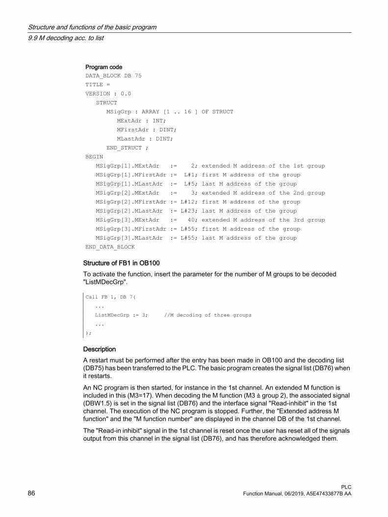
Program codeDATA_BLOCK DB 75TITLE =VERSION : 0.0 STRUCT MSigGrp : ARRAY [1 .. 16 ] OF STRUCT MExtAdr : INT; MFirstAdr : DINT; MLastAdr : DINT; END_STRUCT ;BEGIN MSigGrp[1].MExtAdr := 2; extended M address of the 1st group MSigGrp[1].MFirstAdr := L#1; first M address of the group MSigGrp[1].MLastAdr := L#5; last M address of the group MSigGrp[2].MExtAdr := 3; extended M address of the 2nd group MSigGrp[2].MFirstAdr := L#12; first M address of the group MSigGrp[2].MLastAdr := L#23; last M address of the group MSigGrp[3].MExtAdr := 40; extended M address of the 3rd group MSigGrp[3].MFirstAdr := L#55; first M address of the group MSigGrp[3].MLastAdr := L#55; last M address of the groupEND_DATA_BLOCK
Structure of FB1 in OB100To activate the function, insert the parameter for the number of M groups to be decoded "ListMDecGrp".
Call FB 1, DB 7( ... ListMDecGrp := 3; //M decoding of three groups ... );
DescriptionA restart must be performed after the entry has been made in OB100 and the decoding list (DB75) has been transferred to the PLC. The basic program creates the signal list (DB76) when it restarts.
An NC program is then started, for instance in the 1st channel. An extended M function is included in this (M3=17). When decoding the M function (M3 ≙ group 2), the associated signal (DBW1.5) is set in the signal list (DB76) and the interface signal "Read-inhibit" in the 1st channel. The execution of the NC program is stopped. Further, the "Extended address M function" and the "M function number" are displayed in the channel DB of the 1st channel.
The "Read-in inhibit" signal in the 1st channel is reset once the user has reset all of the signals output from this channel in the signal list (DB76), and has therefore acknowledged them.
Structure and functions of the basic program9.9 M decoding acc. to list
PLC86 Function Manual, 06/2019, A5E47433877B AA

9.10 PLC machine data
General informationThe user has the option of storing PLC-specific machine data in the NC. These machine data can then be processed during power-up of the PLC (OB100). This enables, for example, user options, machine expansion levels, machine configurations, etc., to be implemented.
The interface to read this data is in DB20. However, DB20 is only created by the basic program during power-up when user machine data is used, i.e. sum of GP parameters "UDInt", "UDHex" and "UDReal" is greater than ZERO.
Size of the data areasThe sizes of the individual areas, and thus the total length of the DB20, is set by the following PLC machine data:
● MD14504 $MN_MAXNUM_USER_DATA_INT
● MD14506 $MN_MAXNUM_USER_DATA_HEX
● MD14508 $MN_MAXNUM_USER_DATA_FLOAT
User-relevant basic PLC program parametersThe machine data settings are provided to the user via the following basic PLC program parameters:
● "UDInt"
● "UDHex"
● "UDReal"
NoteUser machine data as ARRAY
The user machine data is always handled internally as an ARRAY. ARRAY variables occupy the memory in the PLC up to the next word limit, i.e. at a BYTE with an even address.
A filler byte is therefore added internally when there is an odd number in MD14506 $MN_MAXNUM_USER_DATA_HEX. This filler byte is included in the FB1 output parameter "UDHex" (number of hexadecimal machine data).
Example:
MD14506 $MN_MAXNUM_USER_DATA_HEX = 3 ⇒ UDHex = 4, although only three hex values can be read.
Data storageThe data is seamlessly stored in the DB20 by the basic PLC program in the following sequence:
1. INT values
2. HEX values (bit arrays)
3. FLOAT values
Structure and functions of the basic program9.10 PLC machine data
PLCFunction Manual, 06/2019, A5E47433877B AA 87

INT and FLOAT values are saved in S7 format.
The hexadecimal values are stored in DB20 in the order in which they are input (use as bit arrays).
Figure 9-4 User data in DB20
Note
If the number of PLC machine data used is increased later, then DB20 must be deleted beforehand. To prevent such extensions in use having any effect on the existing user program, the data in DB20 should be accessed in symbolic form wherever possible, e.g. by means of a structure definition in the UDT.
ExampleFor the project in the example, four INT values, two HEX values for bit information, and one FLOAT value are needed.
Machine data:
MD14510 $MN_USER_DATA_INT[0] = 123MD14510 $MN_USER_DATA_INT[1] = 456MD14510 $MN_USER_DATA_INT[2] = 789MD14510 $MN_USER_DATA_INT[3] = 1011...MD14512 $MN_USER_DATA_HEX[0] = 12MD14512 $MN_USER_DATA_HEX[1] = AC...MD14514 $MN_USER_DA‐TA_FLOAT[0] =
123.456
Structure and functions of the basic program9.10 PLC machine data
PLC88 Function Manual, 06/2019, A5E47433877B AA

Basic PLC program parameters (OB100): CALL FB1, DB7( MCPNum := 1, MCP1In := P#E0.0, MCP1Out := P#A0.0, MCP1StatSend := P#A8.0, MCP1StatRec := P#A12.0, MCP1BusAdr := 6, MCP1Timeout := S5T#700MS, MCP1Cycl := S5T#200MS, NCCyclTimeout := S5T#200MS, NCRunupTimeout := S5T#50S; Basic PLC program parameters (scan at runtime):
l gp_par.UDInt; //=4, l gp_par.UDHex; //=2, l gp_par.UDReal; //=1 )During PLC power-up, DB20 was generated with a length of 28 bytes:
DB20Address Data0.0 1232.0 4564.0 7896.0 10118.0 b#16#129.0 b#16#AC10.0 1.234560e+02
The structure of the machine data used is specified in a UDT:
TYPE UDT20 STRUCT UDInt : ARRAY [0 .. 3] OF INT; UDHex0 : ARRAY [0 .. 15]OF BOOL; UDReal : ARRAY [0 .. 0] OF REAL; //Description as field, for
later expansions END_STRUCT;END_TYPE
Structure and functions of the basic program9.10 PLC machine data
PLCFunction Manual, 06/2019, A5E47433877B AA 89

Note
ARRAY OF BOOL are always sent to even-numbered addresses. For this reason, an array range of 0 to 15 must generally be selected in the UDT definition or all Boolean variables specified individually.
Although only a REAL value is used initially in the example, a field (with one element) has been created for the variable. This ensures that extensions can be made easily in the future without the symbolic address being modified.
Symbolic accessesAn entry is made in the symbol table to allow data access in symbolic form:
Symbol Operand Data typeUData DB20 UDT20
Access operations in user program (list includes only symbolic read access):
... L "UData".UDInt[0]; L "UData".UDInt[1]; L "UData".UDInt[2]; L "UData".UDInt[3]; U "UData".UDHex0[0]; U "UData".UDHex0[1]; U "UData".UDHex0[2]; U "UData".UDHex0[3]; U "UData".UDHex0[4]; U "UData".UDHex0[5]; U "UData".UDHex0[6]; U "UData".UDHex0[7]; ... ... U "UData".UDHex0[15]; L "UData".UDReal[0]; ...
Structure and functions of the basic program9.10 PLC machine data
PLC90 Function Manual, 06/2019, A5E47433877B AA

9.11 Configuration machine control panel, handheld unit, direct keys
GeneralUp to two machine control panels and one handheld unit can be in operation at the same time. There are various connection options (Ethernet/PROFINET, PROFIBUS) for the machine control panel (MCP) and handheld unit (HHU). It is possible to connect two MCPs to different bus systems (mixed operation is only possible on Ethernet and PROFIBUS). This can be achieved using FC1 parameter "MCPBusType". In this parameter, the right-hand decade (units position) is responsible for the first MCP and the left-hand decade (tens position) for the second MCP.
Parameterization of components is always performed by calling the basic program block FC1 in OB100. FC1 saves its parameters in the associated instance data block (DB7, symbolic "LBP_ConfigData"). Separate parameter sets are provided for each machine control panel and the handheld unit. The input/output addresses of the user must be defined in these parameter sets. These input and output addresses are also used in FC19, FC24, FC25, FC26 and FC13. Further, the addresses for status information, PROFIBUS or Ethernet/PROFINET are also to be defined. The default time settings for timeout and cyclic forced retriggering should not be changed. Please refer to the Operator Components manual for further information on MCP and HHU components.
Activation Each component is activated either via the number of machine control panels ("MCPNum" parameter) or, in the case of the handheld unit, via the "BHG" parameter. The MCP and BHG connection settings are entered in FC1 parameters "MCPMPI", "MCPBusType" or "BHG", "BHGMPI".
Handheld unit (HT 2)In the handheld unit the addressing is done via a parameter of the GD parameter set. This was necessary for reasons of compatibility of the parameter names.
ConfigurationEssentially, there are various communication mechanisms for transferring data between the MCP/HHU and PLC. These mechanisms are characterized by the bus connection of the MCP and HHU. In one case (Ethernet), data is transported via the "CP 840D sl".
The parameterization is performed completely via the MCP/HHU parameters in FC1.
In the other case the transmission is via the PLC operating system through the PROFIBUS configuration.
The parameterization is performed via STEP 7 in HW-Config. To enable the basic program to access this data and failure monitoring of MCP/HHU, the addresses set in the FC1 parameters must be made known to the basic program.
An overview of the various coupling mechanisms is shown below. Mixed operation can also be configured.
Structure and functions of the basic program9.11 Configuration machine control panel, handheld unit, direct keys
PLCFunction Manual, 06/2019, A5E47433877B AA 91

If an error is detected due to a timeout, an entry is made in the alarm buffer of the PLC CPU (alarms 400260 to 400262). In this case, the input signals from the MCP or from the handheld unit (MCP1In/MCP2In or BHGIn) are reset to 0. If it is possible to resynchronize the PLC and MCP/HHU, communication is resumed automatically and the error message deleted by the GP.
Note
The abbreviation "(n.r.)" in the tables below means "not relevant".
Ethernet connection (MCPBusType = 5) Without further configuration settings being made, communication takes place directly from the PLC GP via the CP 840D sl. The FC1 parameters listed below are used for parameterization.
The numeric part of the logical name of the component must be entered in "MCP1 BusAdr", "MCP2 BusAdr" or "BHGRecGDNo" (corresponds to the bus address of the node). The logical name is defined via switches on the MCP or terminal box.
Figure 9-5 Ethernet connection
Relevant parameters (FB1)MCP HHUMCPNum=1 or 2 (number of MCPs) HHU = 5 (via CP 840D sl)MCP1In MCP2In BHGInMCP1Out MCP2Out BHGOutMCP1StatSend MCP2StatSend BHGStatSendMCP1StatRec (n.r.) MCP2StatRec (n.r.) BHGStatRecMCP1BusAdr MCP2BusAdr BHGInLen (n.r.)MCP1Timeout (n.r.) MCP2Timeout (n.r.) BHGOutLen (n.r.)MCP1Cycl (n.r.) MCP2Cycl (n.r.) BHGTimeout (n.r.)MCPMPI = FALSE BHGCycl (n.r.)MCP1Stop MCP2Stop BHGRecGDNo MCP1NotSend MCP2NotSend BHGRecGBZNo (n.r.) BHGRecObjNo (n.r.)MCPBusType = b#16#55 (via CP 840D sl) BHGSendGDNo (n.r.) BHGSendGBZNo (n.r.)
Structure and functions of the basic program9.11 Configuration machine control panel, handheld unit, direct keys
PLC92 Function Manual, 06/2019, A5E47433877B AA

Relevant parameters (FB1)MCP HHUMCPSDB210 = FALSE BHGSendObjNo (n.r.)MCPCopyDB77 = FALSE BHGMPI = FALSE BHGStop BHG NotSend
An error entry is also made in the PLC alarm buffer for timeouts. As a result, the following error messages are output at the HMI:
● 400260: MCP 1 failureor
● 400261: MSST 2 failed
● 400262: HHU failure
An MCP or HHU failure is detected immediately after a cold restart even if no data has yet been exchanged between the MCP/HHU and PLC. The monitoring function is activated as soon as all components have signaled "Ready" after power-up.
OP with direct keysThe direct keys of the OPs at the Ethernet bus should be transferred to the PLC. Previously, the direct keys have been transferred to the PLC via the PROFIBUS or via a special cable connection between OP and MCP.
For connecting the direct keys via the Ethernet, this concerns e.g. the "OP 08T", there is a parameterization in the basic program for activating the data transport. The associated parameters are in the instance DB of FC1 (OpKeyNum to OpKeyBusType, see data table). The parameters are provided by the user in the startup OB100 by connecting the parameters at the FC1 call. The bus address and Op1/2KeyStop can also be modified in the cyclic operation by writing the FC1 instance DB DB7.
The transport of the user data of the direct keys runs in the same way as in the case of Ethernet MCP. The data transport can also be stopped and restarted by writing the DB7-parameter "Op1/2KeyStop". During the Stop phase the address of the direct key module (TCU-index or the MCP-address) can also be changed.
After resetting the Stop signal, a connection to the new address is established.
The status of the respective direct-key interfaces can be read in the interface signal:
DB10.DBX104.3 (OP1Key ready)
or
DB10.DBX104.4 (OP2Key ready)
Address direct keys For the parameter Op1/2KeyBusAdr, the TCU index is normally to be used. This affects the OPs, such as OP 08T, OP 12T, which for the direct keys do not have special cable connection to an Ethernet MCP.
If OPs with direct keys have a special cable connection and these are connected to an Ethernet-MCP, then for the parameter Op1/2KeyBusAdr the address of the MCP (DIP-switch setting of
Structure and functions of the basic program9.11 Configuration machine control panel, handheld unit, direct keys
PLCFunction Manual, 06/2019, A5E47433877B AA 93

the MCP) is to be used. Only the data stream of the direct keys (2 bytes) is transferred via the direct key interface.
Warning of connection terminationTo ensure a quick response to an impending termination of the connection between PLC and direct keys, signals are set shortly after the cyclic communicating between PLC and direct keys has failed. If there is still no cyclic communication between PLC and direct keys, the connection is terminated.
The signals for warning against termination of a connection are set in DB10.
● Op1KeyLostPackageWarn (Op1Key)
● Op2KeyLostPackageWarn (Op2Key)
The signals are reset after a connection is terminated or when there is a new connection.
Alarm direct keysAn error entry is also made in the PLC alarm buffer for timeouts. As a result, the following error messages are output at the HMI:
● 400274: Direct key 1 failedor
● 400275: Direct key 2 failed
Control unit switching for direct keysThe user connects Op1/2KeyBusAdr with 0xFF and stop = TRUE in startup block OB100. The direct key address of the M-to-N interface is connected to parameter "Op1KeyBusAdr" via the M-to-N block FB9.
Relevant parameters (FC1)Direct keys e.g. direct keys OP 08TOpKeyNum = 1 or 2 (number of OPs with direct keys) Op1KeyIn Op2KeyIn Op1KeyOut Op2KeyOut OpKey1BusAdr Op2KeyBusAdr Address: TCU indexOp1KeyStop Op2KeyStop Op1KeyNotSend Op2KeyNotSend OpKeyBusType = b#16#55 (via CP 840D sl)
MCP identification Via the identify interface in DB7 it is possible to query the type of the Ethernet component (MCP, HT 2, HT 8 or direct keys) with the relevant parameters at the input/output in cyclic operation:
● Relevant parameters at the input:"IdentMcpBusAdr", "IdentMcpProfilNo", "IdentMcpBusType", "IdentMcpStrobe"
● Relevant parameters at the output:"IdentMcpType", "IdentMcpLengthIn", "IdentMcpLengthOut"
Structure and functions of the basic program9.11 Configuration machine control panel, handheld unit, direct keys
PLC94 Function Manual, 06/2019, A5E47433877B AA

Here the DIP device address or the TCU index at the parameter "IdentMcpBusAdr" is activated by the user program together with setting of the Strobe signal.
The input parameter "IdentMcpProfilNo" is normally to be set to the value 0. This parameter is to be set to the value 1 only in the identification of the direct keys. The parameter "IdentMcpBusType" currently has no significance for a user program and is to be left in its default value.
After resetting the Strobe signal by the basic program, valid output information becomes available to the user. The resetting of the Strobe signals by the basic program can last for several PLC cycles (up to two seconds).
The output parameters should show the user the size of the data areas for the addressed device. Furthermore, it can be defined here whether an HT 2 or an HT 8 or no device is connected to the terminal box. With this information, the MCP channel or the HHU channel can be activated. During cyclic operation, the parameters can be written symbolically by the user program and read via the symbol names of DB7 (LBP_ConfigData).
Relevant parameters (FB1)MCP device identification Input parameters, e.g. OP 08TInput Output Values for direct keys IdentMcpBusAdr IdentMcpType IdentMcpBusAdr = TCU indexIdentMcpBusProfilNo IdentMcpLengthIn IdentMcpBusProfilNo = Value 1IdentMcpBusType IdentMcpLengthOut IdentMcpBusType = Default valueIdentMcpStrobe IdentMcpBusProfilNo ValueMCP, HHU, HT 8, HT 2 B#16#0Direct keys such as e.g. OP 08T, OP 12T B#16#1 IdentMcpType (Mcp-Type) No device connected 0MCP 483C IE (Compact) B#16#80MCP 483C IE B#16#81MCP 310 B#16#82MCP OEM B#16#83MCP DMG B#16#84HT 8 B#16#85TCU_DT (direct keys) B#16#86MCP_MPP B#16#87HT 2 B#16#88OP 08T (direct keys) B#16#89
Structure and functions of the basic program9.11 Configuration machine control panel, handheld unit, direct keys
PLCFunction Manual, 06/2019, A5E47433877B AA 95

PROFIBUS connection on the DP port (MCPBusType = 3) In case of PROFIBUS connection of the MCP, this component must be considered in the hardware configuration setting of STEP 7. The MCP is connected to the standard DP bus of the PLC (not to MPI/DP). The addresses must be stored in the input and output mapping area. These start addresses must also be stored in the pointer parameters of FC1. The FC1 parameters listed below are used for further parameterization.
There is no PROFIBUS variant of the HHU. For this reason, an Ethernet connection is shown for the HHU in this figure. The PROFIBUS slave address must be stored in the parameters "MCP1BusAdr" and "MCP2BusAdr". Enter the pointer to the configured diagnostic address (e.g. P#A8190.0) in "MCPxStatRec".
Figure 9-6 PROFIBUS connection
Relevant parameters (FB1)MCP HHUMCPNum = 1 or 2 (number of MCPs) HHU = 5 (via CP 840D sl)MCP1In MCP2In BHGInMCP1Out MCP2Out BHGOutMCP1StatSend (n.r.) MCP2StatSend (n.r.) BHGStatSendMCP1StatRec MCP2StatRec BHGStatRecMCP1BusAdr MCP2BusAdr BHGInLenMCP1Timeout MCP2Timeout BHGOutLenMCP1Cycl (n.r.) MCP2Cycl (n.r.) BHGTimeout (n.r.)MCPMPI = FALSE BHGCycl (n.r.)MCP1Stop MCP2Stop BHGRecGDNoMCPBusType = b#16#33 BHGRecGBZNo (n.r.) BHGRecObjNo (n.r.)MCPSDB210 = FALSE BHGSendGDNo (n.r.)MCPCopyDB77 = FALSE BHGSendGBZNo (n.r.) BHGSendObjNo (n.r.)
Structure and functions of the basic program9.11 Configuration machine control panel, handheld unit, direct keys
PLC96 Function Manual, 06/2019, A5E47433877B AA

Relevant parameters (FB1)MCP HHU BHGMPI = FALSE BHGStop
MCP failure normally switches the PLC to the STOP state. If this is undesirable, OB 82, OB 86 can be used to avoid a stop. The basic program has, as standard, the OB82 and OB86 call. FC5 is called in these OBs. This FC5 checks whether the failed slave is an MCP. If this is the case, no PLC stop is triggered. Setting "MCPxStop" := TRUE causes the basic program to deactivate the MCP as a slave via SFC12. If the PLC does not switch to the stop state following the failure or fault of the MCP, an alarm message will be generated via the basic program. The interrupt is deleted when the station recovers.
PROFIBUS connection on the MPI/DP port (MCPBusType = 4)With the PROFIBUS connection of the MCP, this component must be considered in the STEP 7 hardware configuration. The MCP is connected on the MPI/DP bus of the PLC.
The addresses must be stored in the input and output mapping area. These start addresses must also be stored in the pointer parameters of FC1. The FC1 parameters listed below are used for further parameterization. There is no PROFIBUS variant of the HHU. For this reason, an Ethernet connection is shown for the HHU in this diagram. The PROFIBUS slave address must be stored in the parameters MCP1BusAdr and MCP2BusAdr. Enter the pointer to the configured diagnostic address (e.g. P#A8190.0) in MCPxStatRec.
Figure 9-7 PROFIBUS connection on the MPI/DP port
Relevant parameters (FB1)MCP HHUMCPNum = 1 or 2 (number of MCPs) HHU = 5 (via CP 840D sl)MCP1In MCP2In BHGInMCP1Out MCP2Out BHGOutMCP1StatSend (n.r.) MCP2StatSend (n.r.) BHGStatSendMCP1StatRec MCP2StatRec BHGStatRec
Structure and functions of the basic program9.11 Configuration machine control panel, handheld unit, direct keys
PLCFunction Manual, 06/2019, A5E47433877B AA 97

Relevant parameters (FB1)MCP HHUMCP1BusAdr MCP2BusAdr BHGInLenMCP1Timeout MCP2Timeout BHGOutLenMCP1Cycl (n.r.) MCP2Cycl (n.r.) BHGTimeout (n.r.)MCPMPI = FALSE BHGCycl (n.r.)MCP1Stop MCP2Stop BHGRecGDNoMCPBusType = b#16#44 BHGRecGBZNo (n.r.) BHGRecObjNo (n.r.)MCPSDB210 = FALSE BHGSendGDNo (n.r.)MCPCopyDB77 = FALSE BHGSendGBZNo (n.r.) BHGSendObjNo (n.r.) BHGMPI = FALSE BHGStop
MCP failure normally switches the PLC to the STOP state. If this is undesirable, then OB82 and OB86 can be used to avoid a PLC stop. The basic program has, as standard, the OB82 and OB86 call. FC5 is called in these OBs. This FC5 checks whether the failed slave is an MCP. If this is the case, no PLC stop is triggered. Setting MCPxStop:= TRUE causes the basic program to deactivate the MCP as a slave via SFC12. If the PLC does not switch to the stop state following the failure or fault of the MCP, an alarm message will be generated via the basic program. The alarm is deleted when the station returns.
PROFINET connection (MCPBusType = 6) In case of PROFINET connection of the MCP, this component must be parameterized in the hardware configuration setting of STEP 7. The MCP is coupled with the PROFINET module of the CPU.
When parameterizing the MCP in HW Config, the addresses should be placed in the input and output mapping area. These start addresses must also be stored in the pointer parameters (MCPxIn and MCPxOut) of FC1. This is because signals are transferred between the MCP and basic program via these parameters. The MCP is also monitored using parameter MCPxIn. This is the reason why parameter MCPxBusAdr is not relevant for this MCP variant.
Enter the pointer to the configured diagnostic address (e.g. P#A8190.0) in MCPxStatRec.
The PROFINET MCP has its own type which should be applied for parameter MCPBusType.
The FC1 parameters listed below are used for further parameterization. There is no PROFIBUS variant of the HHU. An Ethernet port for the HHU is shown in the diagram.
Structure and functions of the basic program9.11 Configuration machine control panel, handheld unit, direct keys
PLC98 Function Manual, 06/2019, A5E47433877B AA

Figure 9-8 PROFINET connection
Relevant parameters (FB1)MCP HHUMCPNum = 1 or 2 (number of MCPs) HHU = 5 (via CP 840D sl)MCP1In MCP2In BHGInMCP1Out MCP2Out BHGOutMCP1StatSend (n.r.) MCP2StatSend (n.r.) BHGStatSendMCP1StatRec MCP2StatRec BHGStatRecMCP1BusAdr (n.r.) MCP2BusAdr (n.r.) BHGInLenMCP1Timeout MCP2Timeout BHGOutLenMCP1Cycl MCP2Cycl BHGTimeout (n.r.)MCPMPI = FALSE BHGCycl (n.r.)MCP1Stop MCP2Stop BHGRecGDNoMCPBusType = b#16#36(as in the figure as example) (6 = PROFINET for MCP1) (3 = PROFIBUS for MCP2)
BHGRecGBZNo (n.r.)
BHGRecObjNo (n.r.)MCPSDB210 = FALSE BHGSendGDNo (n.r.)MCPCopyDB77 = FALSE BHGSendGBZNo (n.r.) BHGSendObjNo (n.r.) BHGMPI = FALSE BHGStop
MCP failure normally switches the PLC to the STOP state. If this is undesirable, then OB82 and OB86 can be used to avoid a PLC stop. The basic program has, as standard, the OB82 and OB86 call. FC5 is called in these OBs. This FC5 checks whether the failed slave is an MCP. If this is the case, no PLC stop is triggered. The input address at parameter MCPxIn is of significance when monitoring for MCPxIn failure.
Structure and functions of the basic program9.11 Configuration machine control panel, handheld unit, direct keys
PLCFunction Manual, 06/2019, A5E47433877B AA 99

Setting MCPxStop := True causes the basic program to deactivate the MCP as a slave via SFC12. If the PLC does not switch to the stop state following the failure or fault of the MCP, an alarm message will be generated via the basic program. The alarm is deleted when the station returns.
9.12 Switchover of machine control panel, handheld unitOnly Ethernet variants support switchover/deactivation of an operator component (MCP or HHU) as standard.
PROFIBUS variant With PROFIBUS variants, this functionality is only possible to a limited extent and with additional user effort.
With the PROFIBUS variant of the MCP, the data area of the DB77 for specified MCP1, MCP2 or HHU can be used for the MCP pointer on FC1. The MCP slave bus address must be set correctly at MCPxBusAdr as this is used as the basis for monitoring. A user program copy routine must copy the signals of the active MCP from the I/O area configured in HW Config to DB77. This enables a number of MCPs on the PROFIBUS to be switched via signals. Set the MCPxStop parameter to TRUE for the switchover phase from one MCP to another.
Control signalsParameters MCP1Stop, MCP2Stop and HTStop stop the communication with individual components (parameter setting = 1). This stop or activation of communication can be applied in the current cycle. However, the change in value must be implemented through the symbolic notation of the parameters and not by means of another FC1 call.
Example: Stopping the transfer from the 1st machine control panel:
SET;S LBP_ConfigData.MCP1Stop;
Setting parameters MCP1Stop, MCP2Stop, HTStop also results in a suppression or deletion of alarms 400260 to 400262.
Switchover of the bus addressIf an existing communication connection to an operator component (MCP or HHU) is to be cancelled and a new communication connection established to a different component (MCP or HHU) with a different communication address, proceed as follows:
1. Stop the communication of the operator component to be disconnected: Parameter MCP1Stop, MCP2Stop or HTStop = 1
2. The communication is stopped when the following applies: DB10, DBX104.0, .1 or .2 == 0
Structure and functions of the basic program9.12 Switchover of machine control panel, handheld unit
PLC100 Function Manual, 06/2019, A5E47433877B AA

3. Change the bus address:
– MCP: FC1 parameter MCP1BusAdr or MCP2BusAdr = <bus address of the new operator component>
– HHU (Ethernet variant): FC1 parameter BHGRecGDNo = <bus address of the new operator component>
4. Enable the communication (possible in the same PLC cycle as point 3): Parameter MCP1Stop, MCP2Stop or HTStop = 0
5. The communication with the new component is active when the following applies: DB10, DBX104.0, .1 or .2 == 1
Switching off the LED flashing of an Ethernet MCPAfter a Power On, MCPs generally indicate the completion of the power-up and waiting for a connection to be established by flashing LEDs. The flashing of the LEDs can be switched off as described in the following. Presently, this behavior cannot be retentively stored on the MCP.
RequirementMCP firmware as of V02.02.04
Setting for switching off the flashingThe Send status must be set in MCPxStop before the start of communication with the MCP. Before the start of communication means either during power-up (OB100) or during cyclic operation (OB1) before the setting of DB7 parameter MCPxStop = FALSE
Setting the Send status: FC1 parameter MCPxStatSend, bit 30 = 0 and bit 31 = 1
There is no feedback of the current status.
ExampleExtract from OB100: (based on the example for MCP1)
CALL "RUN_UP" , "LBP_ConfigData" ... MCP1StatSend := P#A 8.0 ... // Deactivate MCP flashing SET R A 11.6 S A 11.7 ...
Structure and functions of the basic program9.12 Switchover of machine control panel, handheld unit
PLCFunction Manual, 06/2019, A5E47433877B AA 101

Structure and functions of the basic program9.12 Switchover of machine control panel, handheld unit
PLC102 Function Manual, 06/2019, A5E47433877B AA

SPL for Safety Integrated 10Rather than being a function of the basic program, SPL is a user function. The basic program makes a data block (DB18) available for Safety SPL signals and runs a data comparison to ensure the consistency of SPL program data in the NC.
Further informationFunction Manual Safety Integrated
PLCFunction Manual, 06/2019, A5E47433877B AA 103

SPL for Safety Integrated
PLC104 Function Manual, 06/2019, A5E47433877B AA
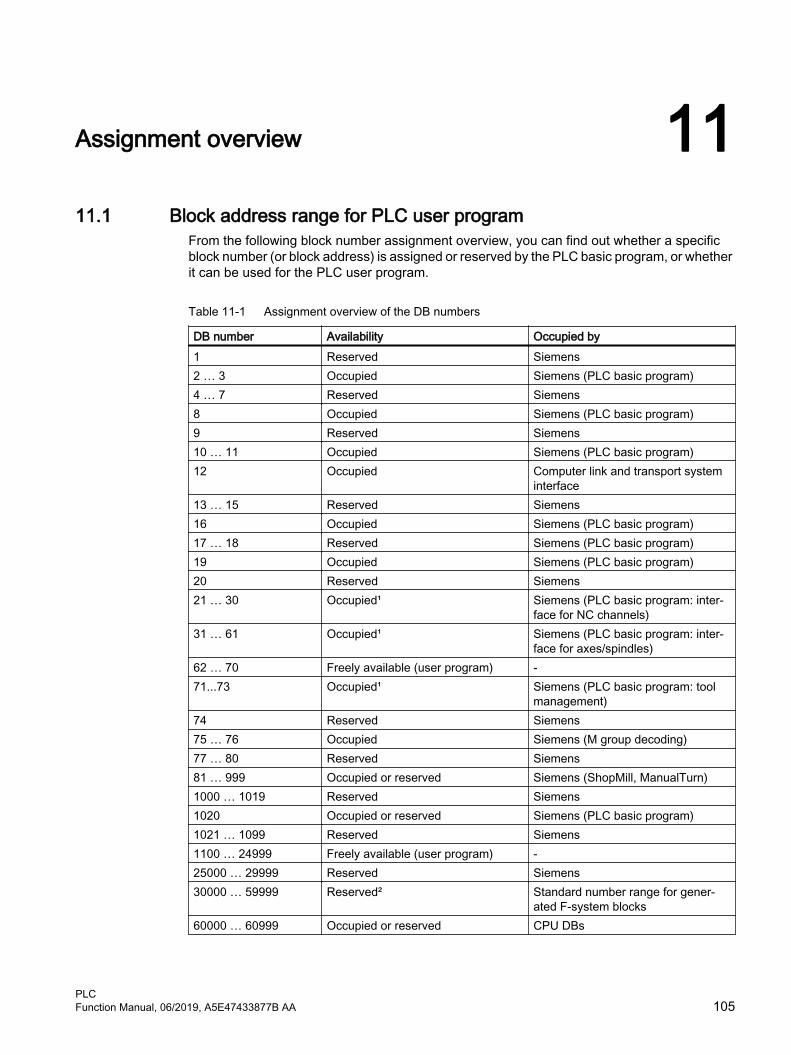
Assignment overview 1111.1 Block address range for PLC user program
From the following block number assignment overview, you can find out whether a specific block number (or block address) is assigned or reserved by the PLC basic program, or whether it can be used for the PLC user program.
Table 11-1 Assignment overview of the DB numbers
DB number Availability Occupied by1 Reserved Siemens2 … 3 Occupied Siemens (PLC basic program)4 … 7 Reserved Siemens8 Occupied Siemens (PLC basic program)9 Reserved Siemens10 … 11 Occupied Siemens (PLC basic program)12 Occupied Computer link and transport system
interface13 … 15 Reserved Siemens16 Occupied Siemens (PLC basic program)17 … 18 Reserved Siemens (PLC basic program)19 Occupied Siemens (PLC basic program)20 Reserved Siemens21 … 30 Occupied¹ Siemens (PLC basic program: inter‐
face for NC channels)31 … 61 Occupied¹ Siemens (PLC basic program: inter‐
face for axes/spindles)62 … 70 Freely available (user program) -71...73 Occupied¹ Siemens (PLC basic program: tool
management)74 Reserved Siemens75 … 76 Occupied Siemens (M group decoding)77 … 80 Reserved Siemens81 … 999 Occupied or reserved Siemens (ShopMill, ManualTurn)1000 … 1019 Reserved Siemens1020 Occupied or reserved Siemens (PLC basic program)1021 … 1099 Reserved Siemens1100 … 24999 Freely available (user program) -25000 … 29999 Reserved Siemens30000 … 59999 Reserved² Standard number range for gener‐
ated F-system blocks60000 … 60999 Occupied or reserved CPU DBs
PLCFunction Manual, 06/2019, A5E47433877B AA 105

¹Not recommended for use, but possible with limitations. Data blocks of channels, axes/spindles and tool management functions that have not been activated can be used by the user, but this can result in conflicts when upgrading or migrating the PLC basic program.
²If you use SINUMERIK Safety Integrated plus (F-PLC), this number range is used for automatically generated F-blocks by default. You can adapt the number range used by the F-system, but you must select a sufficiently large range of numbers.
Table 11-2 Assignment overview of the FB numbers
FB number Availability Occupied by0 Reserved Siemens1 Reserved Siemens (PLC basic program)2 … 3 Occupied Siemens (PLC basic program)4 Reserved Siemens5 Occupied Siemens (PLC basic program)6 Reserved Siemens7 Occupied Siemens (PLC basic program)8 Reserved Siemens9 Occupied Siemens (PLC basic program)10 … 29 Reserved Siemens15 Reserved Siemens (PLC basic program)16…28 Reserved Siemens29 Reserved Siemens (PLC basic program)30…999 Freely available (user program) -1000 … 1009 Reserved Siemens1010 … 1019 Reserved Exclusively available for F blocks of
Safety Integrated plus (F-PLC)1020 Occupied Siemens (PLC basic program)1021 … 1023 Reserved Siemens1024 … 24999 Freely available (user program) -25000 … 32766 Reserved Siemens (PLC basic program)32767 … 65535 Reserved² Standard number range for gener‐
ated F-system blocks
²If you use SINUMERIK Safety Integrated plus (F-PLC), this number range is used for automatically generated F-blocks by default. You can adapt the number range used by the F-system, but you must select a sufficiently large range of numbers.
Table 11-3 Assignment overview of the FC numbers
FC number Availability Occupied by0 Reserved Siemens1 … 3 Occupied Siemens (PLC basic program)4 Reserved Siemens
Assignment overview11.1 Block address range for PLC user program
PLC106 Function Manual, 06/2019, A5E47433877B AA

FC number Availability Occupied by5 Reserved Siemens (PLC basic program)6 … 29 Reserved Siemens30 … 999 Freely available (user program) -1000 … 1023 Reserved Siemens1024 … 24999 Freely available (user program) -25000 Occupied Siemens (PLC basic program)25001 … 32766 Reserved Siemens (PLC basic program)32767 … 65535 Reserved² Standard number range for gener‐
ated F-system blocks
²If you use SINUMERIK Safety Integrated plus (F-PLC), this number range is used for automatically generated F-blocks by default. You can adapt the number range used by the F-system, but you must select a sufficiently large range of numbers.
Assignment overview11.1 Block address range for PLC user program
PLCFunction Manual, 06/2019, A5E47433877B AA 107

Assignment overview11.1 Block address range for PLC user program
PLC108 Function Manual, 06/2019, A5E47433877B AA

PLC functions for HMI (DB19) 1212.1 Channel selection
FunctionThe channel displayed on the HMI, e.g. in the machine start screen, can be selected from the PLC user program via the HMI/PLC interface.
RequirementMore than one channel is parameterized in the NC.
Job and acknowledgment interface
DB19 MeaningDBX32.0 - .5 PLC → HMI Function number: 1 = channel selectionDBX32.6 PLC → HMI Function requestDBX32.7 HMI → PLC Status: 1 = "function being executed"DBB33 PLC → HMI Channel number: 1, 2, 3, ... maximum number of channels
Next channel: FFH
DBB36 HMI → PLC Error identification:● 0: No error ● 1: Invalid function number (DBX32.0 - .5)● 2: Invalid parameter (DBB33 - DBB35)● 3: Error when writing the HMI-internal variable● 10: Channel not present (DBB33)
Functional sequence
PLC → HMIThe PLC user program must maintain the following execution sequence:
1. Check whether the interface is free for a new job:
– DB19.DBX32.6 == 0 (function request)
– DB19.DBX32.7 == 0 (status)
2. If the interface is free, the job data must be entered and the function request set:
– DB19.DBB33 = <channel number>– DB19.DBX32.0 - .5 = 1 (function number)
– DB19.DBX32.6 = 1 (function request)
PLCFunction Manual, 06/2019, A5E47433877B AA 109

HMI → PLCThe HMI makes the following responses for error-free parameterization:
1. Once the HMI has recognized the function request for channel selection, the status is set to "function being performed" and the function request reset:
– DB19.DBX32.7 = 1 (status)
– DB19.DBX32.6 = 0 (function request)
2. Once the channel selection has been performed, the status is reset again and value 0 is set as error identification:
– DB19.DBX32.7 = 0 (status)
– DB19.DBX36 = 0 (error identification)
The HMI makes the following responses for faulty parameterization:
● The function request is reset and the appropriate error identification is set:
– DB19.DBX32.6 = 0 (function request)
– DB19.DBX36 = <error identification>
12.2 Program selection
FunctionPreselected programs/workpieces can be selected for machining by the NC via the PLC/HMI interface.
The preselection is implemented by entering programs/workpiece in files, these are known as PLC program lists (*.ppl).
RequirementsThe following machine data must be set to allow the HMI to process tasks:
MD9106 $MM_SERVE_EXTCALL_PROGRAMS
In order to activate a sector-specific PLC program list, you must set the appropriate machine data and at least the protection level password:
● Area User
– MD51041 $MN_ENABLE_PROGLIST_USER = 1
– Protective level password: 3 (users)
– Program list: /user/sinumerik/hmi/plc/programlist/plc_proglist_user.ppl
● Area Manufacturer (OEM)
– MD51043 $MN_ENABLE_PROGLIST_MANUFACT = 1
– Protective level password: 1 (manufacturer)
– Program list: /oem/sinumerik/hmi/plc/programlist/plc_proglist_manufacturer.ppl
PLC functions for HMI (DB19)12.2 Program selection
PLC110 Function Manual, 06/2019, A5E47433877B AA

Structure of a program listA program list is a text file. Each line contains the following information:
<program number> <program path><program name> [CH=<channel number>]
● Program numberThe program numbers which may be used in a program list depend on the sector:
– user: 1 - 100
– Manufacturer (OEM): 201 - 255
● Program pathThe program path must be completely specified in absolute terms.For specifying the program path, see:Further informationProgramming Manual NC Programming, Section "File and program management" > " Program memory" > "Addressing of program memory files"
● Channel numberSpecifying the channel number "CH=<channel number>" is optional. It is only required if the NC has more than one channel.
The following excerpt as example shows the structure of the user program list:
Program list: plc_proglist_user.ppl1 //DEV2:/MPFDir/PROG_01.MPF CH=12 //DEV2:/MPFDir/PROG_01.MPF CH=2
Generating entries in a program listThe entries in a program list (*.ppl) can be directly edited in the file or entered in screen forms in the user interface.
● Via the user interface for the user areaOperating area "Program Manager" > "ETC key (">")" > "Prog. list"
● Via the user interface for the Manufacturer areaOperating area "Commissioning" > "System data" > "ETC key (">")" > "Prog. list"
Program selection: Job interface
Note
The PLC may only request a new job if the last job has been acknowledged by the HMI: DB19.DBB26 == 0
Program listDB19.DBB16 = <number of the program list>
Number Program list129 /user/sinumerik/hmi/plc/programlist/plc_proglist_user.ppl131 /oem/sinumerik/hmi/plc/programlist/plc_proglist_manufacturer.ppl
PLC functions for HMI (DB19)12.2 Program selection
PLCFunction Manual, 06/2019, A5E47433877B AA 111

Program numberThe program number refers to the programs contained in the selected program list.
DB19.DBB17 = <program number>
● user area: 1 - 100
● oem area: 201 - 255
Requesting program selectionDB19.DBX13.7 = 1
Program selection: Acknowledgment interface
Job acknowledgment● DB19.DBX26.7 == 1 (selection identified)
● DB19.DBX26.3 == 1 (program is selected)
● DB19.DBX26.2 == 1 (error when selecting the program, see error ID DB19.DBB27)
● DB19.DBX26.1 == 1 (job completed)
Error codeDB19.DBB27 == <value>
<Value> Meaning0 No error1 Invalid program list number (DB19.DBB16)3 User-specific program list plc_proglist_main.ppl not found (for DB19.DBB16 ≠ 129, 131 only)4 Invalid program number (DB19.DBB17)5 The job list in the selected workpiece could not be opened6 Error in job list (Job list Interpreter returns error)7 No instructions were found in the job list8 HMI could not execute the selection (SELECT)9 An error with no further details occurred upon selection
10 An error occurred during analysis of the job list11 The instruction is not available12 Invalid instruction (LOAD, UNLOAD, SELECT only)13 Not all channels have the Reset status14 The channel number is invalid
Program selection: Job processingA job to select a program is executed as follows:
1. Checking the acknowledgment byte: DB19.DBB26 == 0If the acknowledgment byte is not 0, then the last job has still not been completed.
2. Specifying the program list: DB19.DBB16
PLC functions for HMI (DB19)12.2 Program selection
PLC112 Function Manual, 06/2019, A5E47433877B AA

3. Specifying the program number: DB19.DBB17
4. Setting the request to select a program: DB19.DBX13.7 = 1
5. Evaluating the acknowledgment and error interface: DB19.DBB26 and DBB27The order is still not completed on the HMI side as long as: DB19.DBX26.3 == 1 (active)The order has been completed on the HMI side if one of the two signals has been set:- DB19.DBX26.1 == 1 (OK)- DB19.DBX26.2 == 1 (error)
6. To complete the order, the program selection request must be reset: DB19.DBX13.7 = 0
7. The HMI signals that it is ready to accept a new order by resetting the acknowledgment byte: DB19.DBB26 == 0
12.3 Activating the key lockThe operator panel keyboard and a keyboard directly connected to the HMI can be locked using the following interface signal
● 1. HMI: DB19.DBX0.2 = <value>
● 2. HMI: DB19.DBX50.2 = <value>
Value Meaning0 Key lock inactive1 Key lock active
12.4 Operating area numbersThe number of the active operating area is normally displayed in: DB19.DBB21
If the HMI monitor is active, the number of the active operating area is no longer displayed in DB19.DBB21, but instead in the user-specific configured area of the HMI monitor (Page 123).
Operating area NumberMachine 201Parameters 205Programming 203Program Manager 202Diagnostics 204Commissioning 206
12.5 Screen numbersThe current screen number is normally displayed in: DB19.DBW24
PLC functions for HMI (DB19)12.5 Screen numbers
PLCFunction Manual, 06/2019, A5E47433877B AA 113

If the HMI monitor is active, the current screen number is no longer displayed in DB19.DBW24, but instead in the user-specific configured area of the HMI monitor (Page 123).
Screen number rangesThe following screen number ranges are available:
● JOG, manual machine (Page 114)
● Reference point approach (Page 119)
● MDA (Page 119)
● AUTOMATIC (Page 120)
● Parameters operating area (Page 120)
● Program operating area (Page 122)
● Program manager operating area (Page 122)
● Diagnostics operating area (Page 122)
12.5.1 Screen numbers: JOG, manual machine
JOG mode
Screen NumberTurning technology
Cycle start screen for all screens that can be taken over 81Milling technology
Cycle start screen for all screens that can be taken over 3Turning/milling
Start screen 19T,S,M 2Set WO 21Positioning 4Face milling 18Stock removal 80Cycle start screen for all user screens 91General settings 1Multi-channel function settings 106Collision avoidance settings 107Measurement log settings 108Swiveling 60All G commands 100Actual zoom value (MCS/WCS) 101Thread synchronizing 102Retract 103
PLC functions for HMI (DB19)12.5 Screen numbers
PLC114 Function Manual, 06/2019, A5E47433877B AA

Screen NumberHandwheel 104Action synchronization 105
Turning technology: Workpiece zeroWorkpiece zero (main menu) 30User screen 31User screen 34User screen 35User screen 36User screen 37User screen 38User screen 40Measure edge Z 5
Turning technology: Workpiece, measurementMeasure tool (main menu) 50Manual X or user screen 51Manual Y 71Manual Z or user screen 52Zoom or user screen 53User screen 54User screen 55Probe calibration X or user screen 56Probe calibration Z or user screen 57Automatic length in Z 58Automatic length in Y 73Automatic length in X 59
Milling technology: Workpiece zeroWorkpiece zero (main menu) 30Measure edge X 5Measure edge X 22Measure edge Z 23User screen 7Align edge or user screen 31Distance 2 edges or user screen 32Right-angled corner 33Any corner or user screen 8Rectangular pocket 341 hole or user screen 92 holes 353 holes 364 holes 37Rectangular spigot 381 circular spigot or user screen 102 circular spigots 39
PLC functions for HMI (DB19)12.5 Screen numbers
PLCFunction Manual, 06/2019, A5E47433877B AA 115

Screen Number3 circular spigots 404 circular spigots 41Set up level 42Probe length calibration or user screen 11Probe radius calibration 12
Milling technology: Workpiece, measurementMeasure tool (main menu) 50Measure length, manual (with milling tool)or measure length in X, manual (with turning tool)or user screen
16
Measure length in Y, manual (with turning tool) 74Measure length in Z, manual (with turning tool) 24Measure diameter, manual or user screen 17Measure length, automatic (with milling tool)or measure length in X, automatic (with turning tool)or user screen
13
Measure length in Y, automatic (with turning tool) 75Measure length in Z, automatic (with turning tool) 25Measure diameter, automatic or user screen 14User screen 51Probe calibration or user screen 15Fixed point calibration or user screen 52
RunMyScreens (only for set JobShopIntegration)User screen for the 1st horizontal softkey 96User screen for the 2nd horizontal softkey 98User screen for the 3rd horizontal softkey 99User screen for the 4th horizontal softkey 94User screen for the 5th horizontal softkey 95User screen for the 6th horizontal softkey 92User screen for the 7th horizontal softkey 97User screen for the 8th horizontal softkey 90User screen for the 9th horizontal softkey 83User screen for the 10th horizontal softkey 82User screen for the 11th horizontal softkey 93User screen for the 12th horizontal softkey 84User screen for the 13th horizontal softkey 85User screen for the 14th horizontal softkey 86User screen for the 15th horizontal softkey 87User screen for the 16th horizontal softkey 88
PLC functions for HMI (DB19)12.5 Screen numbers
PLC116 Function Manual, 06/2019, A5E47433877B AA

JOG mode, manual machine
DB19.DBB24Screen Screen number
Turning/millingTaper turning 61Angle milling 62Stop 63Straight line 1300Straight line all axes 1330Straight line X alpha 1340Straight line Z alpha 1350Circle 1360Drilling 1400Center drilling 1410Drilling, thread centered 1420Drilling, centering 1433Drilling, drilling 1434Drilling, reaming 1435Drilling, boring 1436Drilling, deep hole drilling 1440Drilling, deep hole drilling 2 1441Drilling, tapping 1453Drill thread milling 1455Positions 1473Position row 1474Position grid 1477Position frame 1478Position circle 1475Position pitch circle 1479Obstacle 1476Turning 1500Turning, stock removal 1 1513Turning, stock removal 2 1514Turning, stock removal 3 1515Turning, groove 1 1523Turning, groove 2 1524Turning, groove 3 1525Turning, undercut form E 1533Turning, undercut form F 1534Turning, undercut thread DIN 1535Turning, undercut thread 1536Turning, thread, longitudinal 1543Turning, thread, taper 1544
PLC functions for HMI (DB19)12.5 Screen numbers
PLCFunction Manual, 06/2019, A5E47433877B AA 117

DB19.DBB24Screen Screen numberTurning, thread, facing 1545Turning, thread, chain 1546Turning, cut-off 1550Milling 1600Milling, face milling 1610Milling, rectangular pocket 1613Milling, circular pocket 1614Milling, rectangular spigot 1623Milling, circular spigot 1624Milling, longitudinal groove 1633Milling, circumferential groove 1634Milling, open groove 1635Milling, multi-edge 1640Milling, thread milling 1454Milling, engraving 1670Contour turning 1200Contour turning, new contour / last contour 1210Contour turning, stock removal along contour 1220Contour turning, contour grooving 1230Contour turning, contour plunge turning 1240Contour milling 1100Contour milling, new contour / last contour 1110Contour milling, path milling 1120Contour milling, centering 1130Contour milling, rough drilling 1140Contour milling, contour pocket 1150
Turning technology: SimulationSide view 1740Front view 17503D view 17602-window view 1770Half section 1780
Turning technology: Simultaneous recordingSide view 1741Front view 17513D view 17612-window view 1771Machine space 1791Half section 1781
Milling technology: SimulationTop view 17423D view 1760
PLC functions for HMI (DB19)12.5 Screen numbers
PLC118 Function Manual, 06/2019, A5E47433877B AA

DB19.DBB24Screen Screen numberFrom the front 1744From the rear 1746From the Left 1748From the right 1752Half section 1780Turning view 1782
Milling technology: Simultaneous recordingTop view 17433D view 1761From the front 1745From the rear 1747From the Left 1749From the right 1753Machine space 1791Half section 1781Turning view 1783
12.5.2 Screen numbers: Reference point approach
Screen NumberActual zoom value MCS/WCS 101
12.5.3 Screen numbers: MDA
Screen NumberMDI 20All G commands 100Actual zoom value MCS/WCS 101Handwheel 104Action synchronization 105Program control 210Settings 250
PLC functions for HMI (DB19)12.5 Screen numbers
PLCFunction Manual, 06/2019, A5E47433877B AA 119

12.5.4 Screen numbers: AUTOMATIC
Screen NumberAutomatic 200Overstore 202Program control 210Block search 220General settings 250Multi-channel function settings 106Collision avoidance settings 107All G commands 100Actual zoom value MCS/WCS 101Handwheel 104Action synchronization 105
Turning technology: Simultaneous recordingSide view 243Front view 2443D view 2452-window view 246Machine space 247Half section 253
Milling technology: Simultaneous recordingTop view 2423D view 244From the front 248From the rear 249From the Left 251From the right 252Machine space 247Half section 253Turning view 254
12.5.5 Screen numbers: Parameters operating area
Screen NumberTool list 600Tool wear 610User tool list 620Magazine 630
Work offsetWork offset, active 642Work offset, overview 643
PLC functions for HMI (DB19)12.5 Screen numbers
PLC120 Function Manual, 06/2019, A5E47433877B AA

Screen NumberWork offset, basic 644Work offset, G54 - G509 645Details of work offset, active, overview, basic or G54 - G509 647
User variableR parameters 650Global GUD 1 (SGUD) 660Global GUD 2 (MGUD) 661Global GUD 3 (UGUD) 662Global GUD 4 663Global GUD 5 664Global GUD 6 665Global GUD 7 666Global GUD 8 667Global GUD 9 668Channel GUD 1 (SGUD) 690Channel GUD 2 (MGUD) 691Channel GUD 3 (UGUD) 692Channel GUD 4 693Channel GUD 5 694Channel GUD 6 695Channel GUD 7 696Channel GUD 8 697Channel GUD 9 698Local LUD 681Local LUD/PUD 684
Setting dataWorking area limitation 671Spindle data 670Spindle chuck data 672
Ctrl-EnergyCtrl-Energy, main menu 6170Ctrl-Energy, analysis 6171Ctrl-Energy, profiles 6172Ctrl-Energy, analysis graphic 6176Ctrl-Energy, analysis long-term measurement 6177Ctrl-Energy, analysis details 6179Ctrl-Energy, compare measurements 6178
PLC functions for HMI (DB19)12.5 Screen numbers
PLCFunction Manual, 06/2019, A5E47433877B AA 121

12.5.6 Screen numbers: Program operating area
Screen NumberTurning technology: Simulation
Side view 413Front view 4143D view 4152-window view 416Half section 423
Milling technology: SimulationTop view 4123D view 414From the front 418From the rear 419From the Left 421From the right 422Half section 423Turning view 424
12.5.7 Screen numbers: Program manager operating area
Screen NumberNC directory 300Local drive 325USB / configured drive1 330Configured drive2 340Configured drive3 350Configured drive4 360Configured drive5 383Configured drive6 384Configured drive7 385Configured drive8 386
12.5.8 Screen numbers: Diagnostics operating area
Screen NumberAlarm list 500Messages 501Alarm log 502NC/PLC variable 503
PLC functions for HMI (DB19)12.5 Screen numbers
PLC122 Function Manual, 06/2019, A5E47433877B AA
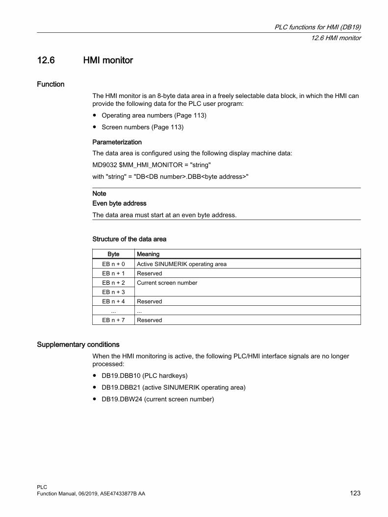
12.6 HMI monitor
FunctionThe HMI monitor is an 8-byte data area in a freely selectable data block, in which the HMI can provide the following data for the PLC user program:
● Operating area numbers (Page 113)
● Screen numbers (Page 113)
ParameterizationThe data area is configured using the following display machine data:
MD9032 $MM_HMI_MONITOR = "string"
with "string" = "DB<DB number>.DBB<byte address>"
NoteEven byte address
The data area must start at an even byte address.
Structure of the data area
Byte MeaningEB n + 0 Active SINUMERIK operating areaEB n + 1 ReservedEB n + 2 Current screen numberEB n + 3EB n + 4 Reserved
... ...EB n + 7 Reserved
Supplementary conditionsWhen the HMI monitoring is active, the following PLC/HMI interface signals are no longer processed:
● DB19.DBB10 (PLC hardkeys)
● DB19.DBB21 (active SINUMERIK operating area)
● DB19.DBW24 (current screen number)
PLC functions for HMI (DB19)12.6 HMI monitor
PLCFunction Manual, 06/2019, A5E47433877B AA 123

Example
Assumptions● Current operating area: "Machine", number: 201
● Actual screen: "AUTOMATIC" start screen, number: 200
● PLC data area: DB60.DBB10
Parameterization● MD9032 $MM_HMI_MONITOR = "DB60.DBB10"
Values in the data area● DB60.DBB10: 201
● DB60.DBW12: 200
PLC functions for HMI (DB19)12.6 HMI monitor
PLC124 Function Manual, 06/2019, A5E47433877B AA

PLC functions for drive components on the integrated PROFIBUS 1313.1 Overview
Using the function described below, input and output data from drive components on the integrated PROFIBUS can be consistently, cyclically read and written from the PLC user program of the hardware PLC. The following boundary conditions must be observed:
● For reading / writing input/output data, the system functions SFC14 / SFC15 must be used.
● The reading / writing of input/output data is always over the entire slot length.
● The function only supports cyclical, non-equidistant data transfer.
● An output slot may not already be occupied on the NC side; (e.g. output slots of drives).
13.2 Performing a start-upPreconditionsBefore the function is put into operation on the NC side, the following preconditions must be satisfied:
● The drive components on the integrated PROFIBUS of the NCU must be fully configured using SIMATIC STEP 7, HW Config.
● The configuration is loaded into the PLC.
NC machine dataThe start addresses of the slots to be transferred cyclically are to be entered into the following machine data:
● Input slots:MD10520 $MN_PLCINTERN_LOGIC_ADDRESS_IN[<Index>] = <Slot address>
● Output slots:MD10525 $MN_PLCINTERN_LOGIC_ADDRESS_OUT[<Index>] = <Slot address>
<Index>: 0, 1, 2, ... (Max no. of slots) – 1
<Slot address>: The slot address parameterized in HW Config
NoteMaximum quantity of data
The sum of all data to be cyclically transferred in inward and outward directions may not currently exceed 2,048 bytes.
PLCFunction Manual, 06/2019, A5E47433877B AA 125

13.3 Example
Determining slot addressesAfter selecting the DP Slave "SINAMICS_Integrated" on the integrated PROFIBUS "PROFIBUS Integrated: DP master system (3)" in the station window of HW Config, its PROFIdrive message frame and associated slot addresses are displayed in the detailed view.
● Message frame 136: Drive
● Message frame 391: Control Unit
● Message frame 370: Infeed
The infeed slot addresses required for parameterization in the NC machines are:
● Input slot: Slot 31, address 6514
● Output slot: Slot 32, address 6514
Figure 13-1 Infeed PROFIBUS message frames
Setting NC machine data● Input slots:
MD10520 $MN_PLCINTERN_LOGIC_ADDRESS_IN[ 0 ] = 6514
● Output slots:MD10525 $MN_PLCINTERN_LOGIC_ADDRESS_OUT[ 0 ] = 6514
Controlling the ALM using FB390 "ALM_Control"The SINUMERIK hardware PLC is connected to the CU320 of SINAMICS S120 through the internal PROFIBUS. The ALM is connected to the CU via DRIVE-CLiQ.
In SINAMICS S120, a control and status message frame can be defined for each module (the CU, ALM, motor modules, etc.). If this is performed for an ALM, this can be switched on and off from the PLC user program.
PLC functions for drive components on the integrated PROFIBUS13.3 Example
PLC126 Function Manual, 06/2019, A5E47433877B AA

The SIMATIC S7 block FB390 "ALM_Control" checks the status of the ALM and enables the user to switch it on or off.
A description of the block and an example project are available for download under the following link to Industry Online Support:
http://support.automation.siemens.com/WW/view/de/49515414
PLC functions for drive components on the integrated PROFIBUS13.3 Example
PLCFunction Manual, 06/2019, A5E47433877B AA 127

PLC functions for drive components on the integrated PROFIBUS13.3 Example
PLC128 Function Manual, 06/2019, A5E47433877B AA
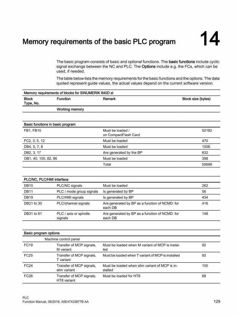
Memory requirements of the basic PLC program 14The basic program consists of basic and optional functions. The basic functions include cyclic signal exchange between the NC and PLC. The Options include e.g. the FCs, which can be used, if needed.
The table below lists the memory requirements for the basic functions and the options. The data quoted represent guide values, the actual values depend on the current software version.
Memory requirements of blocks for SINUMERIK 840D slBlockType, No.
Function Remark Block size (bytes)
Working memory
Basic functions in basic programFB1, FB15 Must be loaded /
on CompactFlash Card 52182
FC2, 3, 5, 12 Must be loaded 470DB4, 5, 7, 8 Must be loaded 1006DB2, 3, 17 Are generated by the BP 632OB1, 40, 100, 82, 86 Must be loaded 398 Total 55698
PLC/NC, PLC/HMI interfaceDB10 PLC/NC signals Must be loaded 262DB11 PLC / mode group signals Is generated by BP 56DB19 PLC/HMI signals Is generated by BP 434DB21 to 30 PLC/channel signals Are generated by BP as a function of NCMD: for
each DB 416
DB31 to 61 PLC / axis or spindle signals
Are generated by BP as a function of NCMD: for each DB
148
Basic program options Machine control panelFC19 Transfer of MCP signals,
M variantMust be loaded when M variant of MCP is instal‐led
92
FC25 Transfer of MCP signals, T variant
Must be loaded when T variant of MCP is installed 92
FC24 Transfer of MCP signals, slim variant
Must be loaded when slim variant of MCP is in‐stalled
100
FC26 Transfer of MCP signals, HT8 variant
Must be loaded for HT8 68
PLCFunction Manual, 06/2019, A5E47433877B AA 129

Basic program options Handheld unitFC13 Display control HHU Can be loaded for handheld units 144 Error/operating messagesFC10 Acquisition FM/BM Load when FM / BM is used 66 ASUPFC9 ASUP start Load when PLC ASUPs are used 128
Basic program options Star/delta changeoverFC17 Star/delta switchover of
MSDLoad for star/delta switchover 114
Spindle controlFC18 Spindle control Load for spindle control from PLC 132 PLC/NC communicationFB2 Read NC variable Load for Read NC variable 76DBn Read NC variable One instance DB per FB2 call: 270FB3 Write NC variable Load for Write NC variable 76DBm Write NC variable One instance DB per FB3 call: 270FB4 PI services Load for PI services 76DBo PI services One instance DB per FB4 call: 130DB16 PI services description Load for PI services 618FB5 Read GUD variables Load for PI services 76DBp Read GUD variables One instance DB per FB5 call: 166 DB15 General communication Global data block for communication 146FB7 PI services 2 Load for PI services 76DBo PI services 2 One instance DB per FB4 call: every 144FC21 Transfer Load with dual-port RAM, ... 164 M to NFB9 Switchover M to N Load with M to N 58 Safety IntegratedFB10 Safety relay Load with Safety option 74FB11 Brake test Load with Safety option 76DB18 Safety data DB for Safety 308 Tool managementFC7 Transfer function
turretLoad for tool management option 84
FC8 Transfer function Load for tool management option 132FC22 Direction selection Load, when direction selection is needed 138DB71 Loading locations Generated by BP as a function of NC MD 40+30*BDB72 Spindles Generated by BP as a function of NC MD 40+48*Sp
Memory requirements of the basic PLC program
PLC130 Function Manual, 06/2019, A5E47433877B AA

Basic program optionsDB73 Revolver Generated by BP as a function of NC MD 40+44*RDB74 Basic function Generated by BP as a function of NC MD 100+(B+
Sp+R)*22 Compile cyclesDB9 Interface
PLC compile cyclesIs generated by BP as a function of NC option 436
Example:Based on the memory requirements in the table above, the memory requirements have been determined for two sample configurations (see table below).
BlockType, No.
Function Remark Block size (bytes)
Working memory
Minimum configuration (1 spindle, 2 axes and T MCP)see above Basic program, base 54688 Interface DBs 1612 MCP 92 Total 56392
BlockType, No.
Function Remark Block size (bytes)
Working memory
Maximum configuration (2 channels, 4 spindles, 4 axes, T MCP)see above Basic program, base 54688see above Interface DBs 2768see above MCP 92see above Error/operating messages 66see above ASUPs 1 ASUP initiation 128see above Concurrent axis For 2 turrets 132see above PLC/NC communication 1 x read variable and 1 x write variable 838see above Tool management 2 turrets with one loading point each 674see above Compile cycles 436 Total 59822
Memory requirements of the basic PLC program
PLCFunction Manual, 06/2019, A5E47433877B AA 131

Memory requirements of the basic PLC program
PLC132 Function Manual, 06/2019, A5E47433877B AA

NC VAR selector 1515.1 Overview
General The PC application "NC VAR selector" retrieves the addresses of required NC variables and prepares them for access in the PLC program (FB2/FB3). This enables the PLC programmer to select NC and drive variables from the entire range of NC and drive variables, to store this selection of variables, and to prepare them with a code generator for the STEP 7 compiler. The data is then stored as ASCII file (*.awl) in the machine CPU program. The "NC VAR Selector" graphic shows this process.
Figure 15-1 NC VAR selector
To store the files created by NC VAR selector, create via Windows Explorer an arbitrary folder where the selected data of NC VAR selector can be stored (data.VAR and data.AWL files). Then transfer and compile the data in a STEP 7 project with "Code - in STEP 7 project". As alternative, insert the "data.awl" file into the STEP 7 machine project via SIMATIC Manager -
PLCFunction Manual, 06/2019, A5E47433877B AA 133

Program LAD/STL/FBD blocks with "Insert - External source". The file is stored in the project structure. Once the file has been transferred, compile the AWL (STL) files with STEP 7.
Note
The latest NC VAR selector can be used for each NC software release (even older versions). For older NC software releases, the variables can also be selected from the latest complete list. The data content in DB120 (default DB for variables) does not depend on the software version. This means, variables selected in an older software release need not be reselected when the software is upgraded.
After starting the "NC VAR selector" application, the variables of the current software version are displayed.
Transfer the variables to the project list (another window). These selected variables can then be stored in an ASCII file, prepared as a STEP 7 source file (.awl) and stored.
After creating a PLC data block by means of the STEP 7 compiler, the PLC programmer is able to read or write NC variables via the basic program function blocks "PUT" and "GET" using the created STEP 7 file.
The project list is also stored as an ASCII file (file extension .var).
The variable list supplied with the "NC VAR selector" tool is adapted to the current software release. This list does not contain any variables (GUD variables) defined by the user. These variables are processed by the function block FB5 in the basic program.
System features, supplementary conditionsThe PC application "NC VAR selector" requires Windows XP or a later operating system.
The assignment of names to variables is described in:Further information:/List sl (Book1); Section: Variablesand also in the variables help file (integrated in NC VAR selector)
NC VAR selector15.1 Overview
PLC134 Function Manual, 06/2019, A5E47433877B AA

15.2 Using NC VAR selector
15.2.1 NC VAR selector user interface
Software user interface structureThe user interface is structured as follows:
① Menu bar② Available buttons③ Drop-down list with the available software versions④ Tab for switching between NC variables and SINAMICS parameters⑤ List of the NC variables (variable list)⑥ List of the selected NC variables (project list)
Figure 15-2 Software user interface
NC VAR selector15.2 Using NC VAR selector
PLCFunction Manual, 06/2019, A5E47433877B AA 135

Buttons
Sym‐bol
Creates a new project. The file selection for the NC variable list opens (applies only when the NC variable list is not already open).Opens an existing project (*.var). The project already contains a stored list of selected variables
Stores the list of selected variables as project in the *.var format.
Prints the project list.
Undoes the last edit step.
Opens the filter dialog to filter the available variables.
Generated STL code with the set properties.
Transfers the generated NCVar data blocks to a STEP 7 project.
Main menuThe main menu contains the following entries:
Menu entry Menu item DescriptionProject New Creates a new project and closes a previously opened project.
Open Opens an existing project.Save Saves a project in *.var format.Save as Saves a project with a new name, with the option of changing the path.Open database Opens an NC variable list in "mdb" database format.Print preview Shows the print preview of the selected NC variables.Print Prints the selected NC variables as list.Exit Exits NC VAR selector.
Edit Undo Undoes the last edit step.Transfer NC varia‐bles
Transfers the selected NC variables to the project list.
Delete in project Deletes selected NC variables from the project.Change alias name in the project
Opens a dialog for changing the alias name of the selected variable in the project list.
Change variable pa‐rameters
Opens a dialog for changing the parameters of a variable in the project list.
Search for / filter NC variables
Opens a dialog for searching for / filtering variables.
Code Settings Opens a dialog with which the code generation can be configured.Generate Initiates the generation of STL code.
Help Online helps for vari‐ous SINUMERIK da‐ta and drive data.
Contains a list of online help for various SINUMERIK data and drive data.
NC VAR selector15.2 Using NC VAR selector
PLC136 Function Manual, 06/2019, A5E47433877B AA

15.2.2 Description of functions
OverviewThe figure below illustrates how NC VAR selector is used within the STEP 7 environment.
Figure 15-3 Application of NC VAR selector in the STEP 7 environment
NC VAR selector generates a list of selected variables from a list of variables and then creates an .awl file that can be compiled by the STEP 7 compiler.
● An *.awl file contains the names and alias names of the NC variables, as well as information about their address parameters. A data block created from this file only contains the address parameters (10 bytes per parameter).
● The created data blocks must always be stored in the machine-specific file storage according to STEP 7 specifications.
● To ensure that the parameterization of the FB2 and FB3 blocks with regard to NC addresses can be implemented with symbols, the freely assignable, symbolic name of the created data block must be included in the STEP 7 symbol list.
NC VAR selector15.2 Using NC VAR selector
PLCFunction Manual, 06/2019, A5E47433877B AA 137

15.2.3 Editing projects
Create a projectThe data relevant for a project is stored in *.var file format. When the NC VAR selector is opened a project is created implicitly and an empty variable list is shown.
1. Perform "Project - New" to create a new project and to close any currently open project.
2. If a project with a variable list already exists, a query opens:
– Discard the settings of the opened project; all settings are deleted.
– Save the project settings. The "Save as" dialog opens.Enter a name for the project
The open project closes. The newly created project does not have any name. To do this, save the project with a new name with "Project - Save as".
Save projectAfter creating a project, only the "Save as" menu item is active.
1. Perform "Project - Save as" to save the project with a new name.
2. If the data of a project has been changed, perform "Project - Save" to save the changes.
Open projectExisting projects can be opened in NC VAR selector.
1. Perform "Project - Open". The "Open" dialog opens.
2. Navigate to the path of the project to be opened.
3. Select the project (*.var) and click "Open".The project with the stored variable list opens, the open project closes.
Print projectThe selected variables can be printed. The layout of the printed documents can be adapted with the print preview.
1. Perform "Project - Print" to send the variable list to the selected printer.
2. Perform "Project - Print preview" to check the print-out before printing and to adapt the layout.
NC VAR selector15.2 Using NC VAR selector
PLC138 Function Manual, 06/2019, A5E47433877B AA

15.2.4 Filtering the variable list
Structure of the variable listThe variable list is created as table. The structure of the table is oriented on the structure of the NC variables:
● Area; the scope of the NC variables is subdivided into areas similar to machines:
– [A]; axis-specific basic settings
– [B]; operating mode groups
– [C]; channels
– [M]; HMI data
– [N]; NC data
– [T]; tool data
– [V]; drive parameters
● Blocks; each area contains several blocks to which the NC variables are assigned.
● Variable name; shows the name of the NC variable.
● System variable / machine data item; shows the name of the corresponding system variable / machine data item.
● Type; shows the data type of the variable.
Select software versionThe available NC variables differ for each software version. The "Software version" drop-down list lists all versions contained in NC VAR selector.
1. Select in the "Software version" drop-down list, the software version to be used for the project.After the selection, a query opens to make the decision whether the currently selected variables should be discarded.
2. Click "Yes" to discard the settings and to display the variables for the specified version.
NC VAR selector15.2 Using NC VAR selector
PLCFunction Manual, 06/2019, A5E47433877B AA 139
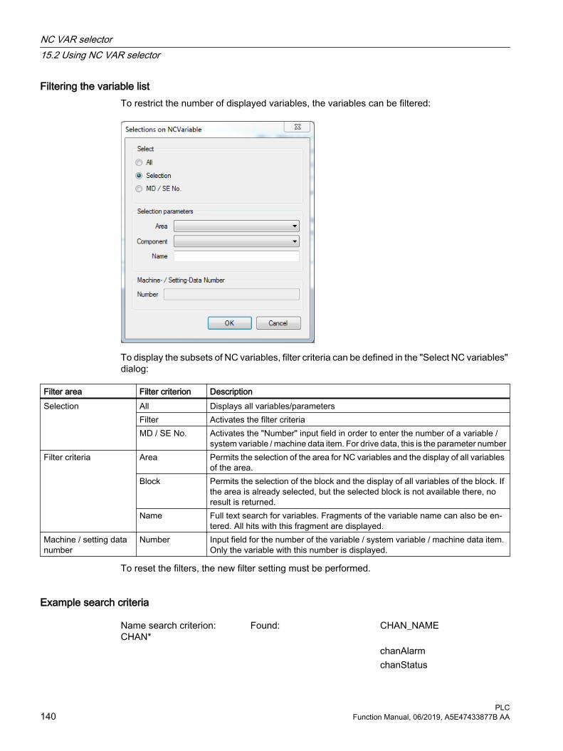
Filtering the variable listTo restrict the number of displayed variables, the variables can be filtered:
To display the subsets of NC variables, filter criteria can be defined in the "Select NC variables" dialog:
Filter area Filter criterion DescriptionSelection All Displays all variables/parameters
Filter Activates the filter criteriaMD / SE No. Activates the "Number" input field in order to enter the number of a variable /
system variable / machine data item. For drive data, this is the parameter numberFilter criteria Area Permits the selection of the area for NC variables and the display of all variables
of the area.Block Permits the selection of the block and the display of all variables of the block. If
the area is already selected, but the selected block is not available there, no result is returned.
Name Full text search for variables. Fragments of the variable name can also be en‐tered. All hits with this fragment are displayed.
Machine / setting data number
Number Input field for the number of the variable / system variable / machine data item. Only the variable with this number is displayed.
To reset the filters, the new filter setting must be performed.
Example search criteria
Name search criterion: CHAN*
Found: CHAN_NAME
chanAlarm chanStatus
NC VAR selector15.2 Using NC VAR selector
PLC140 Function Manual, 06/2019, A5E47433877B AA

channelName chanAssignment
15.2.5 Specifying the project list
Structure of the project listThe project list table has the following structure:
● Area; the scope of the NC variables is subdivided into areas similar to machines.
● Blocks; each area contains several blocks to which the NC variables are assigned.
● Variable name; shows the name of the NC variable.
● S7 alias name; the name that can be used in STEP 7 instead of the variable name.
● Type; shows the data type of the variable.
Transferring variables to the project listAll variables required for creating the data block must be added to the project list.
1. Search for the variables to be added to the project list.
2. Double-click the variable.- OR -
3. Perform "Transfer NC variables" via the context menu.The "Input Area No., Row, Column" dialog opens.
"Input Area No., Row, Column" dialogThe variable parameters are entered in the "Input Area No., Row, Column" dialog
NC VAR selector15.2 Using NC VAR selector
PLCFunction Manual, 06/2019, A5E47433877B AA 141

Figure 15-4 Rows, columns and area numbers
The dialog shows an excerpt from the variable description. Fields in which parameters can be entered are active. The description how the various parameters can be entered correctly is shown below the input fields.
● The value that can be entered in the "Area number" field to control the correct variable is described in this field.
● The meaning of row and column is contained in the variable description. The "Column index" and "Row index" fields there describe the associated inputs.
Parameterizing variablesThe associated required parameters must be entered for the various variable types:
● Single-line variable; only the area number must be entered to access variables of this type. If this is also fixed, the variable can be used without further parameterization.
● Multi-line variable: A variable of this type is a one-dimensional field. The "area number" and a "line" must be entered for access.
● Multi-line and multi-column NC variables: A variable of this type is a two-dimensional field. The "area number", a "line" and a "column number" must be entered for access.
Special case "pointer"By entering a zero (0) as area number, row or column index, it is possible to use the variable in the S7 context as a pointer to this data. When reading or writing this data via the functions "PUT" and "GET", the optional parameters "UnitX", "ColumnX" and "LineX" must be filled with the necessary information.
15.2.6 Deleting a variable from the project list
Delete variableTo delete a variable from the project list, proceed as follows:
1. Select the variable.
2. Perform "Delete in the project" via the context menu.The variable is deleted from the list.
This action can also be undone with the "Edit" menu item.
Note
Deleting of variables results in a change of the absolute addresses of the pointer structures to the variables. When changing the variable selection, it is absolutely necessary to create one or more text files of all user blocks prior to the change. This is the only way to ensure that the assignment of the variables in FB "GET" or FB "PUT" remains correct, even after recompilation.
NC VAR selector15.2 Using NC VAR selector
PLC142 Function Manual, 06/2019, A5E47433877B AA

15.2.7 Alias name
DescriptionThe variable names provided can be up to 32 characters in length. To make variables unique in the data block to be generated, several ASCII characters are added to the selected name. However, the STEP 7 compiler recognizes maximum 24 ASCII characters as a unique S7 variable. Since it cannot be precluded that variable names can only be differentiated by the last 8 character positions, ALIAS names are used for names that are too long. Consequently, the length of the S7 name to be used is checked when a variable is selected. If the name is longer than 24 characters, the user must enter an additional name, which is then used as the alias name.
In this case, the user must ensure that the alias name is unique.
Configuring alias input1. Activate the adaptation of the alias name for the transfer of the variables to the project list:
– "Specify the alias name only when the name is longer than 24 characters"; adapt the alias name only when necessary.
– "Always specify the alias name"; this allows the alias name always to be adapted.
2. An alias name can then be entered every time a variable is transferred.
Editing alias namesTo edit the alias name subsequently, perform "Change alias name in the project" in the context menu of the project list. This action can also be undone with the "Edit" menu item.
15.2.8 Generating code
Generating STL codeTo use the block in STEP 7, the project list must be converted to STL. To do this, generate the STL code with the following settings.
NC VAR selector15.2 Using NC VAR selector
PLCFunction Manual, 06/2019, A5E47433877B AA 143

Perform settingsEnter in the "Code - Settings" menu item, the DB number and the symbol for the DB number for which the code is generated.
● Select in the "Measuring system" tab how the measuring system variables are processed in the PLC.
● The creation for the associated target system is specified in the "Generate" tab.
Perform generationGenerate the STEP 7 file from the selected variable list with extension *.awl:
1. Save the project list as project (*.var).
2. Perform "Code - Generate". The "Save as" dialog opens.
3. Enter a name for the file and specify the path for the *.awl file to be created.
The *.awl file is stored with this name.
NC VAR selector15.2 Using NC VAR selector
PLC144 Function Manual, 06/2019, A5E47433877B AA

15.2.9 Transfer to STEP 7
Transferring a project list to STEP 7The generated AWL file is transferred to a selectable SIMATIC project (program path) and compiled. Furthermore, the symbol can also be transferred. This function is available as of STEP 7 Version 5.1. Before transferring a new AWL file, the file window of the AWL file must be closed in the LAD/FBD/STL editor.
1. First save the project list.
2. Perform "Code - In STEP 7 project".The "STEP 7 projects" dialog opens.
Figure 15-5 Transfer to STEP 7
3. Select the STEP 7 project that contains your program.
4. Activate the "Transfer only DB" checkbox when only the data block should be transferred.
5. Activate the "Transfer DB and Symbol" checkbox when not only the data block, but also symbols should be transferred. Symbols allow the symbolic addressing of variables.
6. Click "OK" to start the operation.SIMATIC Manager opens and the block is stored at "Sources".The data block can be displayed in the "LAD/FBD/STL" program editor.
7. Double-click the data block at "Blocks" in SIMATIC Manager, e.g. DB120.The program editor opens and displays the variables.
NC VAR selector15.2 Using NC VAR selector
PLCFunction Manual, 06/2019, A5E47433877B AA 145

Importing a generated AWL file into STEP 7As alternative to the method described above, the stored STL source can be inserted in a project in SIMATIC Manager.
1. Open the project in SIMATIC Manager and navigate to the "Sources" folder.
2. Perform "Insert - External source".The "Insert external source" dialog opens.
3. Select the AWL file and click "Open".The file is added to the sources of the project.
4. Compile the file so it can be used as block. The block is then displayed in the "Blocks" folder.
15.2.10 Using TIA Portal
STL source for TIA Portal If TIA Portal is used rather than SIMATIC Manager, the "in STEP 7 project" function can be used.
The procedure for TIA Portal follows:
1. Specify the project list.
2. Save the list.
3. Generate an AWL file.
4. Import the AWL file into TIA Portal.
For more information on this topic, refer to the online help of TIA Portal.
15.2.11 Using SINAMICS parameters
SINAMICS parametersIn addition to the "NCData" tab and the variable list of the NC variables, a list of SINAMICS parameters can also be shown.
The list contains the parameters of the "Servo" drive object:
● r parameters: display parameters with which values of the drive axis can be displayed.
● p parameters: read and write parameters with which values can be transferred to the drive axis.
Similar to NC variables, SINAMICS parameters can also be added to the project list and transferred to STEP 7.
NC VAR selector15.2 Using NC VAR selector
PLC146 Function Manual, 06/2019, A5E47433877B AA

Selecting parametersTo select drive parameters, proceed as follows:
1. Search for the variables to be added to the project list.
2. Double-click the variable.- OR -
3. Perform "Transfer NC variables" via the context menu.The "Input Area No., Row, Column" dialog opens.
Figure 15-6 Drive parameters
4. Enter the number of the drive module that corresponds to the deployed drive.
For drives, the area number is the number of the drive module. This corresponds to the component number.
The component number can be found in the topology view (SINUMERIK Operate).
15.2.12 Importing variables and parameters
Importing variable and parameter database filesFor older versions of NC VAR selector, the variable lists of an NC variant exist as ncv*.mdb files. When the lists are opened, all available NC variables / SINAMICS parameters are displayed in the variable list in separate tabs.
The following ncv*.mdb variable list is available:
Variables ListNC variables including machine and setting data: ncv_NcData.mdbParameters of the drive: ncv_SinamicsServo.mdb
NC VAR selector15.2 Using NC VAR selector
PLCFunction Manual, 06/2019, A5E47433877B AA 147

1. Perform "Project - Open database".The "Select NC Variable List" dialog opens.
2. Select the appropriate file (ncv*.mdb) and confirm with "Open".
3. The list opens in NC VAR selector.
15.2.13 Startup, installationThe "NC VAR selector" Windows application is installed by the supplied SETUP program.
The system prerequisites depend on the deployed SIMATIC Manager.
NC VAR selector15.2 Using NC VAR selector
PLC148 Function Manual, 06/2019, A5E47433877B AA

Block descriptions 1616.1 FB1: RUN_UP - basic program, start section
FunctionThe synchronization of NC and PLC is performed during start-up. The data blocks for the NC/PLC user interface are created based on the NC configuration defined via machine data, and the basic program parameters are verified for plausibility. In the event of an error, FB1 passes an error identifier to the diagnostic buffer and switches the PLC to the stop state.
"Restart" startup modeThe integrated PLC only supports the startup mode "Restart". After the basic system initialization, the organization block OB100 "Restart" is always run through first, followed by OB1 "Cyclic mode".
Input parametersOnly the respectively relevant parameters of function block FB1 must be described with user-specific values for parameterization of the basic program. The preset values in the instance data block DB7 of the FB1 do not need to be assigned. The function block FB1 must only be called in the organization block OB100.
Output parametersThe output parameters of function block FB1 can also be read from the cyclical part of the basic program. Two options are available for this purpose:
1. Direct access to the instance data block DB7 of FB1 in symbolic form.Example: "L gp_par.MaxChan", with "gp_par" as the symbolic name of DB7
2. A bit memory is assigned to an output parameter when FB1 is parameterized. The bit memory is then read in the basic program in order to determine the value of the output parameter.Example: "MaxChan":= MW 20
Note
For assigning the FB1 parameters for MCP and HHU, see "Configuration machine control panel, handheld unit, direct keys (Page 91) ".
Declaration of the function
FUNCTION_BLOCK FB1VAR_INPUT
PLCFunction Manual, 06/2019, A5E47433877B AA 149

MCPNum: INT:=1; // 0: No MCP // 1: 1 MCP (default) // 2: 2 MCPs
MCP1In: POINTER; // Start addr. MCP1 input signals MCP1Out: POINTER; // Start addr. MCP1 output signals MCP1StatSend: POINTER; // Status DW for sending MCP1 MCP1StatRec: POINTER; // Status DW for receiving MCP1 MCP1BusAdr: INT:=6; // default MCP1Timeout: S5TIME:= S5T#700MS; MCP1Cycl: S5TIME:= S5T#200MS; MCP2In: POINTER; // Start addr. MCP2 input signals MCP2Out: POINTER; // Start addr. MCP2 output signals MCP2StatSend: POINTER; // Status DW for sending MCP2 MCP2StatRec: POINTER; // Status DW for receiving MCP2 MCP2BusAdr: INT; MCP2Timeout: S5TIME:= S5T#700MS; MCP2Cycl: S5TIME:= S5T#200MS; MCPMPI: BOOL:= FALSE; MCP1Stop: BOOL:= FALSE; MCP2Stop: BOOL:= FALSE; MCP1NotSend: BOOL:= FALSE; MCP2NotSend: BOOL:= FALSE; MCPSDB210: BOOL:= FALSE; MCPCopyDB77: BOOL:= FALSE; MCPBusType: BYTE=B#16#0; HHU: INT:=0; // Handheld unit interface // 0: No HHU // 1: HHU on MPI // 2: HHU on OPI BHGIn : POINTER; // Transmit data of the handheld
unit BHGOut : POINTER; // Receive data of the handheld
unit BHGStatSend : POINTER; // Status DW for sending HHU BHGStatRec : POINTER; // Status DW for receiving HHU BHGInLen : BYTE:= B#16#6; // Input 6 bytes BHGOutLen : BYTE:= B#16#14; // Output 20 bytes BHGTimeout : S5TIME:= S5T#700MS; BHGCycl : S5TIME:= S5T#100MS; BHGRecGDNo : INT:=2; BHGRecGBZNo : INT:=2; BHGRecObjNo : INT:=1; BHGSendGDNo : INT:=2; BHGSendGBZNo : INT:=1; BHGSendObjNo : INT:=1; BHGMPI : BOOL:= FALSE;
Block descriptions16.1 FB1: RUN_UP - basic program, start section
PLC150 Function Manual, 06/2019, A5E47433877B AA

BHGStop : BOOL:= FALSE; BHGNotSend : BOOL:= FALSE; NCCyclTimeout : S5TIME:= S5T#200MS; NCRunupTimeout : S5TIME:= S5T#50S; ListMDecGrp : INT:=0; NCKomm: BOOL:= FALSE; MMCToIF: BOOL:=TRUE; HWheelMMC: BOOL:=TRUE; // Handwheel selection via HMI ExtendAlMsg : BOOL; MCP_IF_TCS: BOOL; ExtendChanAxMsg: BOOL; MsgUser: INT:=10; // Number of user areas in DB 2 UserIR: BOOL:= FALSE; // User programs in OB40, // Observe local data expansion! IRAuxfuT: BOOL:= FALSE; // Evaluate T function in OB40 IRAuxfuH: BOOL:= FALSE; // Evaluate H function in OB40 IRAuxfuE: BOOL:= FALSE; // Evaluate DL function in OB40 UserVersion: POINTER; // Pointer to string variable,
which is displayed in the version display of the user interface
OpKeyNum : INT; Op1KeyIn : POINTER; Op1KeyOut : POINTER; Op1KeyBusAdr : INT; Op2KeyIn : POINTER; Op2KeyOut : POINTER; Op2KeyBusAdr : INT; Op1KeyStop : BOOL; Op2KeyStop : BOOL; Op1KeyNotSend : BOOL; Op2KeyNotSend : BOOL; OpKeyBusType : BYTE ; IdentMcpBusAdr : INT; IdentMcpProfilNo
:BYTE ;
IdentMcpBusType : BYTE ; IdentMcpStrobe : BOOL; END_VAR VAR_OUTPUT MaxBAG: INT; MaxChan: INT; MaxAxis: INT; ActivChan: ARRAY[1..10] OF
BOOL;
Block descriptions16.1 FB1: RUN_UP - basic program, start section
PLCFunction Manual, 06/2019, A5E47433877B AA 151
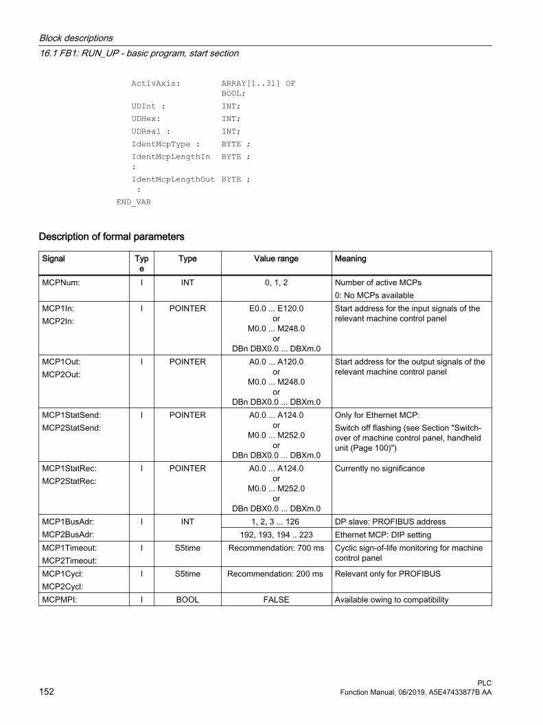
ActivAxis: ARRAY[1..31] OF BOOL;
UDInt : INT; UDHex: INT; UDReal : INT; IdentMcpType : BYTE ; IdentMcpLengthIn
:BYTE ;
IdentMcpLengthOut :
BYTE ;
END_VAR
Description of formal parameters
Signal Type
Type Value range Meaning
MCPNum: I INT 0, 1, 2 Number of active MCPs0: No MCPs available
MCP1In:MCP2In:
I POINTER E0.0 ... E120.0or
M0.0 ... M248.0or
DBn DBX0.0 ... DBXm.0
Start address for the input signals of the relevant machine control panel
MCP1Out:MCP2Out:
I POINTER A0.0 ... A120.0or
M0.0 ... M248.0or
DBn DBX0.0 ... DBXm.0
Start address for the output signals of the relevant machine control panel
MCP1StatSend:MCP2StatSend:
I POINTER A0.0 ... A124.0or
M0.0 ... M252.0or
DBn DBX0.0 ... DBXm.0
Only for Ethernet MCP:Switch off flashing (see Section "Switch‐over of machine control panel, handheld unit (Page 100)")
MCP1StatRec:MCP2StatRec:
I POINTER A0.0 ... A124.0or
M0.0 ... M252.0or
DBn DBX0.0 ... DBXm.0
Currently no significance
MCP1BusAdr:MCP2BusAdr:
I INT 1, 2, 3 ... 126 DP slave: PROFIBUS address192, 193, 194 .. 223 Ethernet MCP: DIP setting
MCP1Timeout:MCP2Timeout:
I S5time Recommendation: 700 ms Cyclic sign-of-life monitoring for machine control panel
MCP1Cycl:MCP2Cycl:
I S5time Recommendation: 200 ms Relevant only for PROFIBUS
MCPMPI: I BOOL FALSE Available owing to compatibility
Block descriptions16.1 FB1: RUN_UP - basic program, start section
PLC152 Function Manual, 06/2019, A5E47433877B AA

Signal Type
Type Value range Meaning
MCP1Stop:MCP2Stop:
I BOOL 0 (FALSE), 1 (TRUE) 0: Start transfer of the machine control panel signals1: Stop transfer of machine control panel signalsDP slave: Slave deactivated
MCP1NotSend :MCP2NotSend:
I BOOL 0 (FALSE), 1 (TRUE) 0: Send and receive operation activated1: Receive machine control panel signals only
MCPSDB210: I BOOL false Available owing to compatibilityMCPCopyDB77: I BOOL false Available owing to compatibilityMCPBusType: I BYTE 3, 4, 5, 6 b#16#yx:
● Bus type MCP1: Lower nibble (x)● Bus type MCP2: Upper nibble (y)3: PROFIBUS4: PROFIBUS on the MPI/DP port5: Ethernet6: PROFINETMixed mode is possible (see Section "Con‐figuration machine control panel, handheld unit, direct keys (Page 91)")
HHU: I INT 0, 5 Handheld unit interface:0: No HHU5: HHU on Ethernet
BHGIn: I POINTER E0.0 ... E124.0or
M0.0 ... M252.0or
DBn DBX0.0 ... DBXm.0
Start address PLC receive data from hand‐held unit
BHGOut: I POINTER A0.0 ... A124.0or
M0.0 ... M252.0or
DBn DBX0.0 ... DBXm.0
Start address PLC transmit data to hand‐held unit
BHGStatSend: I POINTER A0.0 ... A124.0or
M0.0 ... M252.0or
DBn DBX0.0 ... DBXm.0
Available owing to compatibility
BHGStatRec: I POINTER A0.0 ... A124.0or
M0.0 ... M252.0or
DBn DBX0.0 ... DBXm.0
Available owing to compatibility
BHGInLen: I BYTE HHU default: B#16#6 (6 Byte)
Available owing to compatibility
BHGOutLen: I BYTE HHU default: B#16#14 (20 byte)
Available owing to compatibility
Block descriptions16.1 FB1: RUN_UP - basic program, start section
PLCFunction Manual, 06/2019, A5E47433877B AA 153
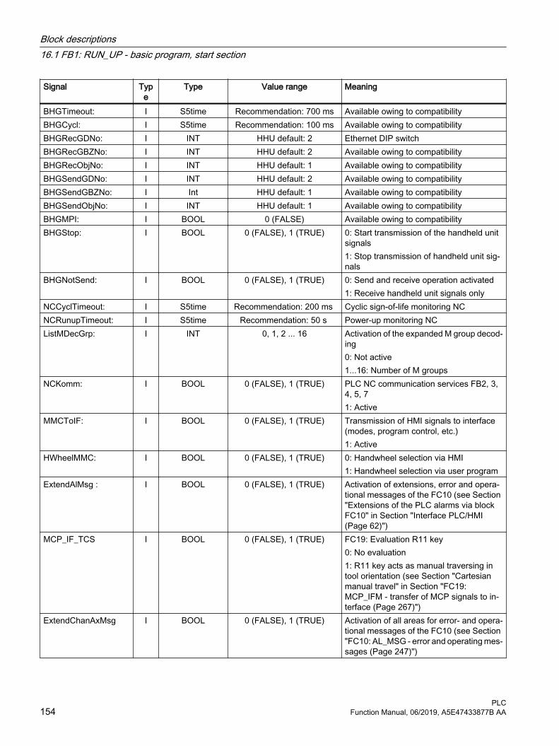
Signal Type
Type Value range Meaning
BHGTimeout: I S5time Recommendation: 700 ms Available owing to compatibilityBHGCycl: I S5time Recommendation: 100 ms Available owing to compatibilityBHGRecGDNo: I INT HHU default: 2 Ethernet DIP switchBHGRecGBZNo: I INT HHU default: 2 Available owing to compatibilityBHGRecObjNo: I INT HHU default: 1 Available owing to compatibilityBHGSendGDNo: I INT HHU default: 2 Available owing to compatibilityBHGSendGBZNo: I Int HHU default: 1 Available owing to compatibilityBHGSendObjNo: I INT HHU default: 1 Available owing to compatibilityBHGMPI: I BOOL 0 (FALSE) Available owing to compatibilityBHGStop: I BOOL 0 (FALSE), 1 (TRUE) 0: Start transmission of the handheld unit
signals1: Stop transmission of handheld unit sig‐nals
BHGNotSend: I BOOL 0 (FALSE), 1 (TRUE) 0: Send and receive operation activated1: Receive handheld unit signals only
NCCyclTimeout: I S5time Recommendation: 200 ms Cyclic sign-of-life monitoring NCNCRunupTimeout: I S5time Recommendation: 50 s Power-up monitoring NCListMDecGrp: I INT 0, 1, 2 ... 16 Activation of the expanded M group decod‐
ing0: Not active1...16: Number of M groups
NCKomm: I BOOL 0 (FALSE), 1 (TRUE) PLC NC communication services FB2, 3, 4, 5, 71: Active
MMCToIF: I BOOL 0 (FALSE), 1 (TRUE) Transmission of HMI signals to interface (modes, program control, etc.)1: Active
HWheelMMC: I BOOL 0 (FALSE), 1 (TRUE) 0: Handwheel selection via HMI1: Handwheel selection via user program
ExtendAlMsg : I BOOL 0 (FALSE), 1 (TRUE) Activation of extensions, error and opera‐tional messages of the FC10 (see Section "Extensions of the PLC alarms via block FC10" in Section "Interface PLC/HMI (Page 62)")
MCP_IF_TCS I BOOL 0 (FALSE), 1 (TRUE) FC19: Evaluation R11 key0: No evaluation1: R11 key acts as manual traversing in tool orientation (see Section "Cartesian manual travel" in Section "FC19: MCP_IFM - transfer of MCP signals to in‐terface (Page 267)")
ExtendChanAxMsg I BOOL 0 (FALSE), 1 (TRUE) Activation of all areas for error- and opera‐tional messages of the FC10 (see Section "FC10: AL_MSG - error and operating mes‐sages (Page 247)")
Block descriptions16.1 FB1: RUN_UP - basic program, start section
PLC154 Function Manual, 06/2019, A5E47433877B AA

Signal Type
Type Value range Meaning
MsgUser: I INT 0, 1, 2 ... 64 Number of user areas (DB2) – depends on parameter "ExtendAIMsg"
UserIR: I BOOL 0 (FALSE), 1 (TRUE) Local data extension OB40 required for processing of signals from the user
IRAuxfuT: I BOOL 0 (FALSE), 1 (TRUE) Evaluate T function in OB40IRAuxfuH: I BOOL 0 (FALSE), 1 (TRUE) Evaluate H function in OB40IRAuxfuE: I BOOL 0 (FALSE), 1 (TRUE) Evaluate DL function in OB40UserVersion: I POINTER P#DBn.DBXx.0 Pointer to string variable, which is dis‐
played in the version display of the user interfaceThe string variable has the following nota‐tion (max. 41 characters):"<Name> <version xx.xx.xx> <date yy/mm/dd>"Example: "Test version 07.06.02 13/06/04"
OpKeyNum : I INT 0, 1, 2 Number of active direct key modules 0: No Ethernet direct control keys available
Op1KeyIn:Op2KeyIn:
I POINTER P#Ex.0or
P#Mx.0or
P#DBn.DBXx.0.
Start address for the input signals of the affected direct control key modules
Op1KeyOut :Op2KeyOut:
I POINTER P#Ax.0or
P#Mx.0or
P#DBn.DBXx.0.
Start address for the output signals of the affected direct control key modules
Op1KeyBusAdr :Op2KeyBusAdr:
I INT 1, 2, 3 ... 191 Direct control keys via Ethernet: TCU index
Op1KeyStop :Op2KeyStop:
I BOOL 0 (FALSE), 1 (TRUE) 0: Start transmission of the direct key sig‐nals1: Stop transmission of the direct key sig‐nals
Op1KeyNotSend:Op2KeyNotSend:
I BOOL 0 (FALSE), 1 (TRUE) 0: Send and receive operation activated1: Receive direct control key signals only
OpKeyBusType : I BYTE b#16#55 EthernetIdentMcpBusAdr : I INT 1, 2, 3 ... 254 Only IE devicesIdentMcpProfilNo : I BYTE 0, 1 Profile of a device
0: Complete device1: Only direct keys
IdentMcpBusType: I BYTE b#16#5 Only IE devicesIdentMcpStrobe: I BOOL 0 (FALSE), 1 (TRUE) 1: Activate queryMaxBAG: O INT 1, 2, 3 ... 10 Number of mode groupsMaxChan: O INT 1, 2, 3 ... 10 Number of channelsMaxAxis: O INT 1, 2, 3 ... 31 Number of axes
Block descriptions16.1 FB1: RUN_UP - basic program, start section
PLCFunction Manual, 06/2019, A5E47433877B AA 155

Signal Type
Type Value range Meaning
ActivChan: O ARRAY[1...10] OF BOOL
0 (FALSE), 1 (TRUE) Bit string for active channels
ActivAxis: O ARRAY [1..31] OF BOOL
0 (FALSE), 1 (TRUE) Bit string for active axes
UDInt : O INT 0, Quantity of INTEGER machine data in DB20
UDHex: O INT --- Quantity of hexadecimal machine data in DB2, where applicable including the filler byte
UDReal : O INT --- Quantity of REAL machine data in DB20IdentMcpType : O BYTE 0, B#16#80, B#16#81,
B#16#82 ... B#16#89MCP type
IdentMcpLengthIn: O BYTE --- Length of MCP input data (MCP → PLC)IdentMcpLengthOut : O BYTE --- Length of MCP output data (PLC → MCP)
If an error occurs during communication with a machine control panel (MCP) or handheld unit (HHU), the following alarm is displayed at the HMI and the input signals (MCP1In, MCP2In or BHGIn) are set to the zero value:
Error case: MCP/HHU● Alarm 400260: "MCP 1 failure"
● Alarm 400261: "MCP 2 failure"
● Alarm 400262: "HHU failure"
If a resynchronization is possible between PLC and MCP/HHU, communication is resumed, the error message at the HMI is deleted by the basic program, and process values transferred into the input signals (MCP1In, MCP2In or BHGIn) once again.
Example: FB1 call in the OB100
ORGANIZATION_BLOCK OB100VAR_TEMP OB100_EV_CLASS : BYTE ; OB100_STRTUP : BYTE ; OB100_PRIORITY : BYTE ; OB100_OB_NUMBR : BYTE ; OB100_RESERVED_1 : BYTE ; OB100_RESERVED_2 : BYTE ; OB100_STOP : WORD; OB100_RESERVED_3 : WORD; OB100_RESERVED_4 : WORD; OB100_DATE_TIME : DATE_AND_TIME;END_VAR BEGIN
Block descriptions16.1 FB1: RUN_UP - basic program, start section
PLC156 Function Manual, 06/2019, A5E47433877B AA
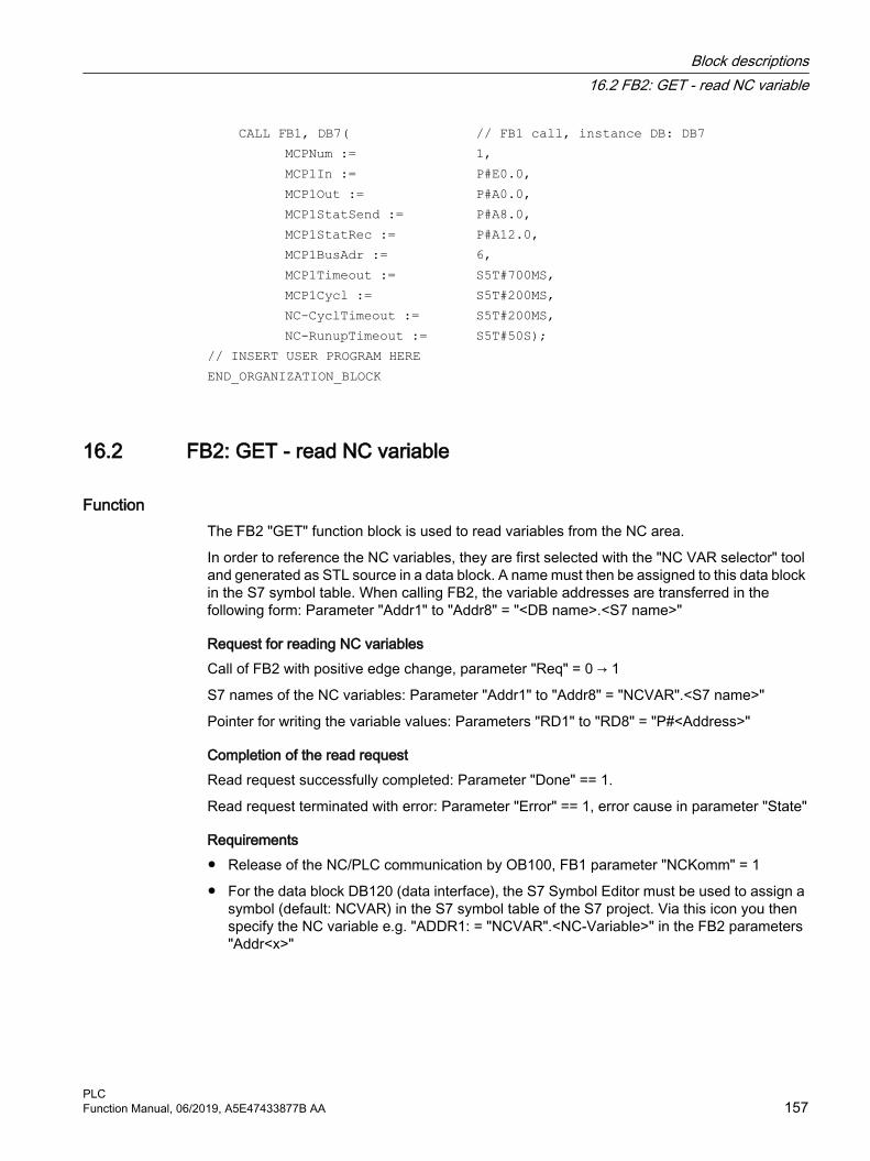
CALL FB1, DB7( // FB1 call, instance DB: DB7 MCPNum := 1, MCP1In := P#E0.0, MCP1Out := P#A0.0, MCP1StatSend := P#A8.0, MCP1StatRec := P#A12.0, MCP1BusAdr := 6, MCP1Timeout := S5T#700MS, MCP1Cycl := S5T#200MS, NC-CyclTimeout := S5T#200MS, NC-RunupTimeout := S5T#50S);// INSERT USER PROGRAM HEREEND_ORGANIZATION_BLOCK
16.2 FB2: GET - read NC variable
Function The FB2 "GET" function block is used to read variables from the NC area.
In order to reference the NC variables, they are first selected with the "NC VAR selector" tool and generated as STL source in a data block. A name must then be assigned to this data block in the S7 symbol table. When calling FB2, the variable addresses are transferred in the following form: Parameter "Addr1" to "Addr8" = "<DB name>.<S7 name>"
Request for reading NC variablesCall of FB2 with positive edge change, parameter "Req" = 0 → 1
S7 names of the NC variables: Parameter "Addr1" to "Addr8" = "NCVAR".<S7 name>"
Pointer for writing the variable values: Parameters "RD1" to "RD8" = "P#<Address>"
Completion of the read requestRead request successfully completed: Parameter "Done" == 1.
Read request terminated with error: Parameter "Error" == 1, error cause in parameter "State"
Requirements● Release of the NC/PLC communication by OB100, FB1 parameter "NCKomm" = 1
● For the data block DB120 (data interface), the S7 Symbol Editor must be used to assign a symbol (default: NCVAR) in the S7 symbol table of the S7 project. Via this icon you then specify the NC variable e.g. "ADDR1: = "NCVAR".<NC-Variable>" in the FB2 parameters "Addr<x>"
Block descriptions16.2 FB2: GET - read NC variable
PLCFunction Manual, 06/2019, A5E47433877B AA 157

Boundary conditions● FB2 has multi-instance capability.
● A separate instance or separate instance DB must be assigned from the user area to each call of the FB2.
● When channel-specific variables are read, only variables from exactly one channel may be addressed via "Addr1" to "Addr8" if FB2 is called.
● When drive-specific variables are read, only variables from exactly one SERVO drive object may be addressed via "Addr1" to "Addr8" if FB2 is called. The SERVO drive object must be assigned to a machine axis of the NC. The line index corresponds to the logical drive number.
● In a read job, only variables from the same area, channel, or drive object can be read.
Note
Error caseWhen reading variables from different channels or drive objects, or simultaneously from a channel and a drive object, an error message is output:● "Error" == TRUE● "State" == W#16#02
Variable addressingFor some NC variables, it is necessary to select "Area no." and/or "Line" or "Column" from the NC VAR selector. It is possible to select a basic type, i.e. "Area no.", "Line" and "Column" are preassigned "0". The values of the "Area no.", "Line" and "Column" specified by the NC VAR selector are checked for a "0" in FB2. If an NC-VAR selector value == "0", the corresponding value of the FB2 parameter is adopted. To do this, the FB2 parameters "Unit<x>", "Column<x>" and "Line<x>", with <x> = 1 - 8, must be written before FB2 is called.
Table 16-1 Parameter match
FB2 parameter NC VAR selectorUnit Area no.
Column ColumnLine Line
Variables within one group can be combined in a job:
Group Area1 C[1] N B A T2 C[2] N B A T3 V[.] H[.] --- --- ---
The same rules apply for channels 3 to 10 as for group 1 and group 2 shown in the example.
Block descriptions16.2 FB2: GET - read NC variable
PLC158 Function Manual, 06/2019, A5E47433877B AA

Note
The number of usable variables can be less than eight when simultaneously reading several variables of the "String" type.
Declaration of the function
FUNCTION_BLOCK FB2VAR_INPUT Req : BOOL;
NumVar : INT;Addr1 : ANY;Unit1 : BYTE ;Column1 : WORD;Line1 : WORD;Addr2 : ANY;Unit2 : BYTE ;Column2 : WORD;Line2 : WORD;Addr3 : ANY;Unit3 : BYTE ;Column3 : WORD;Line3 : WORD;Addr4 : ANY;Unit4 : BYTE ;Column4 : WORD;Line4 : WORD;Addr5 : ANY;Unit5 : BYTE ;Column5 : WORD;Line5 : WORD;Addr6 : ANY;Unit6 : BYTE ;Column6 : WORD;Line6 : WORD;Addr7 : ANY;Unit7 : BYTE ;Column7 : WORD;Line7 : WORD;Addr8 : ANY;Unit8 : BYTE ;Column8 : WORD;Line8 : WORD;
END_VAR
Block descriptions16.2 FB2: GET - read NC variable
PLCFunction Manual, 06/2019, A5E47433877B AA 159

VAR_OUTPUT Error : BOOL;
NDR : BOOL;State : WORD;
END_VAR
VAR_IN_OUT RD1 : ANY;
RD2 : ANY;RD3 : ANY;RD4 : ANY;RD5 : ANY;RD6 : ANY;RD7 : ANY;RD8 : ANY;
END_VAR
Description of formal parameters
Parameter Type
Type Value range Meaning
Req: I BOOL --- Job start with positive signal edgeNumVar: I INT 1 ... 8 Number of variables to be read:
"Addr1" - "Addr8"Addr1 - Addr8: I ANY "DBName".<VarName> Variable identifiers from NC Var
selectorUnit1 - Unit8: I BYTE --- Area address, optional for variable
addressingColumn1 - Column8:
I WORD --- Column address, optional for vari‐able addressing
Line1 - Line8: I WORD --- Line address, optional for variable addressing
Error: O BOOL 0 (FALSE), 1 (TRUE) 1: Negative acknowledgement of job or execution of job impossible
NDR : O BOOL 0 (FALSE), 1 (TRUE) 1: Job successfully executed. Data is available
State: O WORD --- See paragraph "Error identifiers"RD1 - RD8: I/O ANY P#Mm.n BYTE x ...
P#DBnr.dbxm.n BYTE xTarget area for read data
Block descriptions16.2 FB2: GET - read NC variable
PLC160 Function Manual, 06/2019, A5E47433877B AA

Error identifiers
NC variables
State Meaning
NoteHigh byte 1)
Low byte
1 - 8 1 Access error ---0 2 Error in job Incorrect compilation of variables in a job0 3 Negative acknowledgement,
job not executableInternal error, possible remedy: ● Check job data● NC reset
1 - 8 4 Insufficient local user memo‐ry available
Data type of the read variable is greater than specified in "RD1" - "RD8"
0 5 Format conversion error Error on conversion of var. type double: Vari‐able is not within the S7 REAL area
0 6 FIFO full Job must be repeated since queue is full0 7 Option not set FB1 parameter "NCKomm" is not set
1 - 8 8 Incorrect target area (RD) "RD1" - "RD8" must not be local data0 9 Transmission occupied Job must be repeated
1 - 8 10 Error in variable addressing "Unit" or "Column"/"Line" contains value 00 11 Address of variable invalid Check "Addr" (or variable name), "Area", "Unit"0 12 NumVar == 0 Check parameter "NumVar"
1 - 8 13 ANY data reference incorrect Requested "NcVar" data has not been para‐meterized
1) High byte > 0 ⇒ Number of the variable in which the error occurred
Drive-specific variablesIf an error occurs while reading/writing a drive-specific variable (DB1200.DBX3000.1 == 1), an error number is displayed in the access result which is based on the error numbers defined in the PROFIdrive profile.
State Meaningx <Error number of PROFIdrive profile> + 20H or 36D
Determining the significance of the access result:
1. Calculation of the error number of the PROFIdrive profile<Error number of PROFIdrive profile> = result of access - 20H or 36D.
2. Determining the significance of the error number of the PROFIdrive profileThe error numbers of the PROFIdrive profile are described in:Further informationFunction Manual, SINAMICS S120 Drive Functions; Section "Communication" > "Communication according to PROFIdrive" > "Acyclic communication" > "Structure of the requests and responses" > Subsection "Error values in parameter responses"
Block descriptions16.2 FB2: GET - read NC variable
PLCFunction Manual, 06/2019, A5E47433877B AA 161

Configuration stepsProceed as follows to read NC variables:
● Select variables with the NC VAR selector
● Save selected variables in a *.VAR file
● Generate a STEP 7 *.STL source file
● Generate a DB with the associated address data
● Enter the symbol for the generated DB in the symbol table so that it is possible to access the address parameters symbolically in the user program
● Parameterizing the FB2
Pulse diagram
① User: Set request, Req = 0 → 1② FB2 successfully completed, NDR = 1
User: Reset request, IF NDR == 1 THEN Req = 0③ User: IF NDR == 1 THEN reset request: 1 → 0④ FB2 reset job confirmation, NDR = 0⑤ User: IF NDR == 0 AND Error == 0 THEN reset request Req = 1 → 0 not permissible⑥ FB2 completed with errors, Error = 1
User: Reset request, IF NDR == 1 OR Error == 1 THEN Req = 0, possible further error handling
Call exampleReading three channel-specific machine data from channel 1, whose address specifications are stored in DB120.
Specification of dataThe data is selected with the NC VAR selector and saved in the DB120.VAR file. Then the DB120.AWL file is created from this.
S7 (ALIAS) names are selected.
Block descriptions16.2 FB2: GET - read NC variable
PLC162 Function Manual, 06/2019, A5E47433877B AA
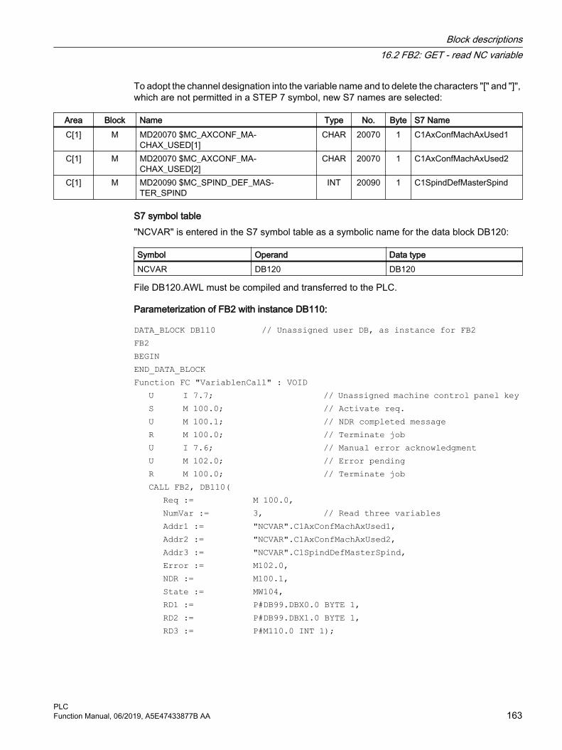
To adopt the channel designation into the variable name and to delete the characters "[" and "]", which are not permitted in a STEP 7 symbol, new S7 names are selected:
Area Block Name Type No. Byte S7 NameC[1] M MD20070 $MC_AXCONF_MA‐
CHAX_USED[1]CHAR 20070 1 C1AxConfMachAxUsed1
C[1] M MD20070 $MC_AXCONF_MA‐CHAX_USED[2]
CHAR 20070 1 C1AxConfMachAxUsed2
C[1] M MD20090 $MC_SPIND_DEF_MAS‐TER_SPIND
INT 20090 1 C1SpindDefMasterSpind
S7 symbol table"NCVAR" is entered in the S7 symbol table as a symbolic name for the data block DB120:
Symbol Operand Data typeNCVAR DB120 DB120
File DB120.AWL must be compiled and transferred to the PLC.
Parameterization of FB2 with instance DB110:
DATA_BLOCK DB110 // Unassigned user DB, as instance for FB2FB2BEGINEND_DATA_BLOCKFunction FC "VariablenCall" : VOID U I 7.7; // Unassigned machine control panel key
S M 100.0; // Activate req.U M 100.1; // NDR completed messageR M 100.0; // Terminate jobU I 7.6; // Manual error acknowledgmentU M 102.0; // Error pendingR M 100.0; // Terminate jobCALL FB2, DB110( Req := M 100.0,
NumVar := 3, // Read three variablesAddr1 := "NCVAR".C1AxConfMachAxUsed1,Addr2 := "NCVAR".C1AxConfMachAxUsed2,Addr3 := "NCVAR".C1SpindDefMasterSpind,Error := M102.0,NDR := M100.1,State := MW104,RD1 := P#DB99.DBX0.0 BYTE 1,RD2 := P#DB99.DBX1.0 BYTE 1,RD3 := P#M110.0 INT 1);
Block descriptions16.2 FB2: GET - read NC variable
PLCFunction Manual, 06/2019, A5E47433877B AA 163

Example: Variable addressingReading two R parameters from channel 1, whose address specifications are stored in DB120 as the basic type. The R parameter number is parameterized via parameter "Line<x>".
DATA_BLOCK DB120VERSION : 0.0STRUCT C1_RP_rpa0_0:
STRUCTSYNTAX_ID : BYTE := B#16#82;area_and_unit : BYTE := B#16#41;column : WORD := W#16#1;line : WORD := W#16#0;block type : BYTE := B#16#15;NO. OF LINES : BYTE := B#16#1;type : BYTE := B#16#F;length : BYTE := B#16#8;END_STRUCT;
END_STRUCT;BEGINEND_DATA_BLOCKCALL FB2, DB110( Req := M 0.0,
NumVar := 2,Addr1 := "NCVAR".C1_RP_rpa0_0,Line1 := W#16#1,Addr2 := "NCVAR".C1_RP_rpa0_0,Line2 := W#16#2,Error := M 1.0,NDR := M 1.1,State := MW 2,RD1 := P#M 4.0 REAL 1,RD2 := P#M 24.0 REAL 1);
Classification of data types
Table 16-2 Classification of data types
NC-internal or BTSS data type S7 data typeDOUBLE REALDOUBLE REAL2
REAL REALLONG DINT
INTEGER DINTUINT_32 DWORD
Block descriptions16.2 FB2: GET - read NC variable
PLC164 Function Manual, 06/2019, A5E47433877B AA

NC-internal or BTSS data type S7 data typeINT_16 INT
UINT_16 WORDUNSIGNED WORD
CHAR CHAR or BYTESTRING STRINGBOOL BOOL
DATETIME DATE_AND_TIME
ExampleFor example, to be able to read an NC variable of the type DOUBLE without adapting the format, an ANY pointer with REAL2 type must be specified in the destination area "RDx" (e.g.: P#M100.0 REAL2). If the basic PLC program identifies a variable of the type DOUBLE as REAL2 target type when reading, the data is adopted as a 64 bit floating point number in the PLC data area.
16.3 FB3: PUT - write NC variables
Function The FB3 "PUT" function block is used to write variables from the NC area.
In order to reference the NC variables, they are first selected with the "NC VAR selector" tool and generated as STL source in a data block. A name must then be assigned to this data block in the S7 symbol table. When calling FB3, the variable addresses are transferred in the following form: Parameter "Addr1" to "Addr8" = "<DB name>".<S7 name>
Request for writing NC variablesCall of FB3 with positive edge change, parameter "Req" = 0 → 1
S7 names of the NC variables: Parameter "Addr1" to "Addr8" = "NCVAR".<S7 name>"
Pointer for writing the variable values: Parameters "RD1" to "RD8" = "P#<Address>"
Completion of the write requestWrite request successfully completed: Parameter "Done" == 1.
Write request terminated with error: Parameter "Error" == 1, error cause in parameter "State"
Requirements● Release of the NC/PLC communication by OB100, FB1 parameter "NCKomm" = 1
● For the data block DB120 (data interface), the S7 Symbol Editor must be used to assign a symbol (default: NCVAR) in the S7 symbol table of the S7 project. Via this symbol, the NC variable is then specified in the FB3 parameters "Addr<x>", e.g. "ADDR1":= "NCVAR".<NC-Variable>"
Block descriptions16.3 FB3: PUT - write NC variables
PLCFunction Manual, 06/2019, A5E47433877B AA 165

Boundary conditions● FB3 has multi-instance capability.
● A separate instance or a separate instance DB must be assigned from the user area to each call of the FB3.
● In order to define machine data and GUD without a password, the protection level of the data you want to access must be redefined to the lowest level.Further information
– Commissioning Manual; Section: "Protection levels concept"
– Programming Manual NC Programming; Section: "Define protection levels for user data"
● When channel-specific variables are written, only variables from exactly one channel may be addressed via "Addr1" to "Addr8" if FB2 is called.
● When drive-specific variables are written, only variables from exactly one SERVO drive object may be addressed via "Addr1" to "Addr8" if FB2 is called. The SERVO drive object must be assigned to a machine axis of the NC. The line index corresponds to the logical drive number.
● In a write job, only variables from the same area, channel, or drive object can be written.
Note
Error caseWhen writing variables from different channels or drive objects, or simultaneously from a channel and a drive object, an error message is output:● "Error" == TRUE● "State" == W#16#02
Variable addressingFor some NC variables, it is necessary to select "Area no." and/or "Line" or "Column" from the NC VAR selector. It is possible to select a basic type, i.e. "Area no.", "Line" and "Column" are preassigned "0". The values of the "Area no.", "Line" and "Column" specified by the NC VAR selector are checked for a "0" in FB2. If an NC-VAR selector value == "0", the corresponding value of the FB3 parameter is adopted. To do this, the FB3 parameters "Unit<x>", "Column<x>" and "Line<x>", with <x> = 1 - 8, must be written before FB3 is called.
FB3 parameter NC VAR selectorUnit<x> Area no.
Column<x> ColumnLine<x> Line
NC variables within one group can be combined in a job:
Group Area1 C[1] N B A T2 C[2] N B A T
Block descriptions16.3 FB3: PUT - write NC variables
PLC166 Function Manual, 06/2019, A5E47433877B AA

Group Area3 V[.] H[.] --- --- ---
The same rules apply for channels 3 to 10 as for group 1 and group 2 shown in the example.
Note
The number of usable variables can be less than eight when simultaneously writing several variables of the "String" type.
Declaration of the function
FUNCTION_BLOCK FB3VAR_INPUT
Block descriptions16.3 FB3: PUT - write NC variables
PLCFunction Manual, 06/2019, A5E47433877B AA 167

Req : BOOL;NumVar : INT;Addr1 : ANY;Unit1 : BYTE ;Column1 : WORD;Line1 : WORD;Addr2 : ANY;Unit2 : BYTE ;Column2 : WORD;Line2 : WORD;Addr3 : ANY;Unit3 : BYTE ;Column3 : WORD;Line3 : WORD;Addr4 : ANY;Unit4 : BYTE ;Column4 : WORD;Line4 : WORD;Addr5 : ANY;Unit5 : BYTE ;Column5 : WORD;Line5 : WORD;Addr6 : ANY;Unit6 : BYTE ;Column6 : WORD;Line6 : WORD;Addr7 : ANY;Unit7 : BYTE ;Column7 : WORD;Line7 : WORD;Addr8 : ANY;Unit8 : BYTE ;Column8 : WORD;Line8 : WORD;
END_VARVAR_OUTPUT Error : BOOL;
Done : BOOL;State : WORD;
END_VARVAR_IN_OUT
Block descriptions16.3 FB3: PUT - write NC variables
PLC168 Function Manual, 06/2019, A5E47433877B AA

SD1 : ANY;SD2 : ANY;SD3 : ANY;SD4 : ANY;SD5 : ANY;SD6 : ANY;SD7 : ANY;SD8 : ANY;
END_VAR
Description of formal parameters
Signal Type
Type Value range Meaning
Req: I BOOL - Job start with positive signal edgeNumVar: I INT 1 ... 8 Number of variables to be written:
"Addr1" - "Addr8"Addr1 - Addr8: I ANY "DBName".<VarName> Variable identifiers from NC Var
selectorUnit1 - Unit8: I BYTE - Area address, optional for variable
addressingColumn1 - Column8: I WORD - Column address, optional for vari‐
able addressingLine1 - Line8: I WORD - Line address, optional for variable
addressingError: O BOOL 0 (FALSE), 1 (TRUE) Negative acknowledgment of job
or execution of job impossibleDone: O BOOL 0 (FALSE), 1 (TRUE) Job successfully executed.State: O WORD - See paragraph "Error identifiers"SD1 - SD8: I/O ANY P#Mm.n BYTE x...
P#DBnr.dbxm.n BYTE xData to be written
Error identifiers
NC variables
State Meaning
Note High
byte 1)Low byte
1 - 8 1 Access error ---0 2 Error in job Incorrect compilation of variables in a job0 3 Negative acknowledgement,
job not executableInternal error, try: ● Check job● NC reset
1 - 8 4 Data areas or data types do not match or string is empty
Check data in "SD1" - "SD8"
Block descriptions16.3 FB3: PUT - write NC variables
PLCFunction Manual, 06/2019, A5E47433877B AA 169

State Meaning
Note High
byte 1)Low byte
0 6 FIFO full Job must be repeated since queue is full0 7 Option not set FB1 parameter "NCKomm" is not set
1 - 8 8 Incorrect target area (SD) "SD1" - "SD8" must not be local data0 9 Transmission occupied Job must be repeated
1 - 8 10 Error in variable addressing "Unit" or "Column"/"Line" contains value 00 11 Variable address invalid or
variable is read-onlyCheck "Addr" (or variable name), "Area", "Unit"
0 12 NumVar == 0 Check parameter "NumVar"1 - 8 13 ANY data reference incorrect Requested "NcVar" data has not been para‐
meterized1 - 8 15 User data too long Remedy: Write fewer variables per job or use
shorter string variables1) High byte > 0 ⇒ Number of the variable in which the error occurred
Drive-specific variablesIf an error occurs while reading/writing a drive-specific variable (DB1200.DBX3000.1 == 1), an error number is displayed in the access result which is based on the error numbers defined in the PROFIdrive profile.
State Meaningx <Error number of PROFIdrive profile> + 20H or 36D
Determining the significance of the access result:
1. Calculation of the error number of the PROFIdrive profile<Error number of PROFIdrive profile> = result of access - 20H or 36D.
2. Determining the significance of the error number of the PROFIdrive profileThe error numbers of the PROFIdrive profile are described in:Further informationFunction Manual, SINAMICS S120 Drive Functions; Section "Communication" > "Communication according to PROFIdrive" > "Acyclic communication" > "Structure of the requests and responses" > Subsection "Error values in parameter responses"
Configuration stepsTo write NC variables, the same configuration steps are required as for reading NC variables. It is useful to store the address data of all NC variables to be read or written in a DB.
Block descriptions16.3 FB3: PUT - write NC variables
PLC170 Function Manual, 06/2019, A5E47433877B AA
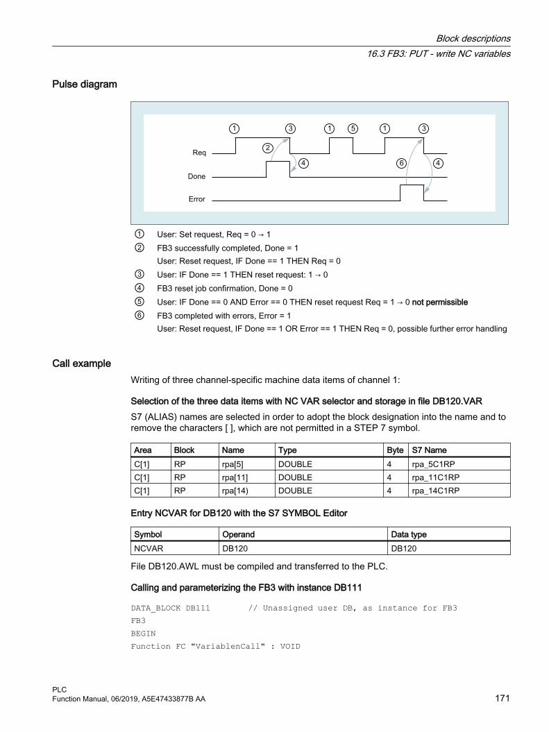
Pulse diagram
① User: Set request, Req = 0 → 1② FB3 successfully completed, Done = 1
User: Reset request, IF Done == 1 THEN Req = 0③ User: IF Done == 1 THEN reset request: 1 → 0④ FB3 reset job confirmation, Done = 0⑤ User: IF Done == 0 AND Error == 0 THEN reset request Req = 1 → 0 not permissible⑥ FB3 completed with errors, Error = 1
User: Reset request, IF Done == 1 OR Error == 1 THEN Req = 0, possible further error handling
Call exampleWriting of three channel-specific machine data items of channel 1:
Selection of the three data items with NC VAR selector and storage in file DB120.VARS7 (ALIAS) names are selected in order to adopt the block designation into the name and to remove the characters [ ], which are not permitted in a STEP 7 symbol.
Area Block Name Type Byte S7 NameC[1] RP rpa[5] DOUBLE 4 rpa_5C1RPC[1] RP rpa[11] DOUBLE 4 rpa_11C1RPC[1] RP rpa[14) DOUBLE 4 rpa_14C1RP
Entry NCVAR for DB120 with the S7 SYMBOL Editor
Symbol Operand Data typeNCVAR DB120 DB120
File DB120.AWL must be compiled and transferred to the PLC.
Calling and parameterizing the FB3 with instance DB111
DATA_BLOCK DB111 // Unassigned user DB, as instance for FB3FB3BEGINFunction FC "VariablenCall" : VOID
Block descriptions16.3 FB3: PUT - write NC variables
PLCFunction Manual, 06/2019, A5E47433877B AA 171

END_DATA_BLOCK U I 7.7; // Unassigned machine control panel key
S M 100.0; // Activate req.U M 100.1; // Done completed messageR M 100.0; // Terminate jobU I 7.6; // Manual error acknowledgmentU M 102.0; // Error pendingR M 100.0; // Terminate jobCALL FB3, DB111( Req := M 100.0,
NumVar := 3, // Write three variablesAddr1 := "NCVAR".rpa_5C1RP, Addr2 := "NCVAR".rpa_11C1RP, Addr3 := "NCVAR".rpa_14C1RP, Error := M102.0, Done := M100.1, State := MW104, SD1 := P#DB99.DBX0.0 REAL 1, SD2 := P#DB99.DBX4.0 REAL 1, SD3 := P#M110.0 REAL 1);
Example: Variable addressingWriting two R parameters from channel 1, whose address specifications are stored in DB120 as the basic type. The R parameter number is parameterized via parameter LineX.
DATA_BLOCK DB120VERSION : 0.0STRUCT C1_RP_rpa0_0:
STRUCTSYNTAX_ID : BYTE := B#16#82;area_and_unit : BYTE := B#16#41;column : WORD := W#16#1;line : WORD := W#16#0;block type : BYTE := B#16#15;NO. OF LINES : BYTE := B#16#1;type : BYTE := B#16#F;length : BYTE := B#16#8;END_STRUCT;
END_STRUCT;BEGINEND_DATA_BLOCKCALL FB3, DB122(
Block descriptions16.3 FB3: PUT - write NC variables
PLC172 Function Manual, 06/2019, A5E47433877B AA

Req := M 10.0,NumVar := 2,Addr1 := "NCVAR".C1_RP_rpa0_0,Line1 := W#16#1,Addr2 := "NCVAR".C1_RP_rpa0_0,Line3 := W#16#2Error := M 11.0,Done := M 11.1,State := MW 12,SD1 := P#M 4.0 REAL 1,SD2 := P#M 24.0 REAL 1);
Classification of data typesSee table "Assignment of the data types" in Section "FB2: GET - read NC variable (Page 157)".
16.4 FB4: PI_SERV - request PI service
Function The function block FB4 "PI_SERV" is used to start PI services.
The available PI services are described in the following chapters with their specific parameters. An overview of the available PI services can be found in: List of available Pl services (Page 177)
Note
Due to the large number of "WVar" parameters, it is recommended that you use the function block FB7 instead of FB4. See Section "FB7: PI_SERV2 - request PI service (Page 210)".
Start of a PI serviceRequest to start a PI service: Call of the FB4 with positive edge, parameter "Req" = 0 → 1
Completion of a PI servicePI service successfully completed: Parameter "Done" == 1.
PI service completed with error: Parameter "Error" == 1, error cause in parameter "State"
Requirements● Release of the NC/PLC communication by OB100, FB1 parameter "NCKomm" = 1
● For the data block DB16 (data interface of the PI services), the S7 Symbol Editor must be used to assign a symbol (default: PI) in the S7 symbol table of the S7 project. The requested PI service is then specified via this symbol in the FB4 parameter "PIService", e.g. "PIService:= "PI".<PI service>"
Block descriptions16.4 FB4: PI_SERV - request PI service
PLCFunction Manual, 06/2019, A5E47433877B AA 173

Boundary conditions● A separate instance or a separate instance DB must be assigned from the user area to each
call of the FB4.
● The start of a PI service (FB4 call with "Req" = 1) is only permitted in the cyclic part of the PLC basic program (OB1). If the PI service is not started (FB4 call with "Req" = 0), the parameters can also be written in the start-up part of the PLC basic program (OB100). The PI service can then be started using the already written parameters in the cyclic part of the PLC basic program (OB1) by calling FB4 with "Req" = 1.
● The execution of a PI service generally extends over several PLC cycles.
Declaration of the function
FUNCTION_BLOCK FB4VAR_INPUT Req : BOOL;
PIService: ANY;Unit: INT;Addr1 : ANY;Addr2 : ANY;Addr3 : ANY;Addr4 : ANY;WVar1: WORD;WVar2: WORD;WVar3: WORD;WVar4: WORD;WVar5: WORD;WVar6: WORD;WVar7: WORD;WVar8: WORD;WVar9: WORD;WVar10: WORD;
END_VARVAR_OUTPUT Error : BOOL;
Done : BOOL;State : WORD;
END_VAR
Block descriptions16.4 FB4: PI_SERV - request PI service
PLC174 Function Manual, 06/2019, A5E47433877B AA

Description of formal parameters
Signal Type
Type Value range Meaning
Req: I BOOL 0 (FALSE), 1 (TRUE) Job requestPIService: I ANY "<DBName>".<PI serv‐
ice> Requested PI service● <DBName>: symbol name for
DB16, default: "PI"● <PI service>: List of available Pl
services (Page 177)Unit: I INT 1, 2, 3, ... Area numberAddr1 to Addr4: I ANY "<DBName>".<Var‐
Name>Reference to a stringSignificance depends on selected PI service
WVar1 to WVar10: I WORD -32768 ... 327678000H ... 7FFFH
INTEGER or WORD variableSignificance depends on selected PI service
Error: O BOOL 0 (FALSE), 1 (TRUE) Error status1: Negative acknowledgment of job or job could not be executed (see the "State" parameter for the cause of the error)
Done: O BOOL 0 (FALSE), 1 (TRUE) Job status1: Job successfully executed
State: O WORD 1) Error codeOnly relevant if "Error" == 1
1) State Meaning Note3 Negative acknowledgement, job not ex‐
ecutableInternal error, possibly remedied by an NC RESET
6 FIFO full Repeat the command7 Option not set FB1 parameter "NCKomm" is not set13 Addr1 ... Addr4: Reference invalid Specify missing string14 PI service is unknown The PI service specified in the "PISer‐
vice" parameter is unknown. → check the notation/spelling.
15 Addr1 ... Addr4: String too long Check the string lengths
Call example
Function: Program selection in channel 1 (main program and workpiece program)Entry of PI service for DB16 and STR for DB124 using the S7 SYMBOL editor:
ParameterizationSymbol Operand Data type
PI DB16 DB16STR DB124 DB124
Block descriptions16.4 FB4: PI_SERV - request PI service
PLCFunction Manual, 06/2019, A5E47433877B AA 175

DATA_BLOCK DB126 // Instance for FB4, unassigned user DBFB4BEGINEND_DATA_BLOCK// ------------------------------------------------------------------------DATA_BLOCK DB124 STRUCT PName: string[32]:= '_N_TEST_MPF
';// Main program
Path: string[32]:= '/_N_MPF_DIR/';
// Main program path
PName_WST: string[32]:= '_N_ABC_MPF'; // Workpiece program Path_WST: string[32]:= '/_N_WCS_DIR/
_N_ZYL_WPD';// Workpiece program path
END_STRUCTBEGINEND_DATA_BLOCK// -------------------------------------------------------------------------Function FC "PICall": VOID U I 7.7; // Unassigned machine control panel key S M 0.0; // Activate req. U M 1.1; // Done completed message R M 0.0; // Terminate job U I 7.6; // Manual error acknowledgment U M 1.0; // Error pending R M 0.0; // Terminate job CALL FB4, DB126 ( Req:= M0.0, PIService:= "PI".SELECT // PI service: SELECT Unit:= 1, // Channel 1 Addr1:= "STR".Path, // Main program: Path Addr2:= "STR".PName, // Main program: Program // Addr1:= "STR".Path_WST, // Workpiece: Path // Addr2:= "STR".PName_WST, // Workpiece: Program Error:= M1.0, Done:= M1.1, State:= MW2 );
Block descriptions16.4 FB4: PI_SERV - request PI service
PLC176 Function Manual, 06/2019, A5E47433877B AA

Flow diagram
① User: Set request, Req = 0 → 1② FB4: PI service successfully completed, Done = 1
User: Reset request, IF Done == 1 THEN Req = 0③ User: IF Done == 1 THEN reset request: 1 → 0④ FB4: Reset job confirmation, Done = 0⑤ User: IF Done == 0 AND Error == 0 THEN reset request Req = 1 → 0 not permissible⑥ FB4: PI service completed with errors, Error = 1
User: Reset request, IF Done == 1 OR Error == 1 THEN Req = 0, possible further error handling
16.4.1 List of available Pl services
General PI services
PI service FunctionASUP (Page 178) Assign interruptCANCEL (Page 179) Execute cancelCONFIG (Page 180) Reconfiguration of tagged machine data DIGION (Page 180) Digitizing onDIGIOF (Page 180) Digitizing offFINDBL (Page 181) Activate block search LOGIN (Page 181) Activate passwordLOGOUT (Page 181) Reset passwordNCRES (Page 182) Trigger NC-RESETSELECT (Page 182) Select program for processing for one channelSETUDT (Page 183) Sets the current user data to activeSETUFR (Page 183) Activate user frameRETRAC (Page 183) Retraction of the tool in the tool direction
Block descriptions16.4 FB4: PI_SERV - request PI service
PLCFunction Manual, 06/2019, A5E47433877B AA 177

PI services of tool management
PI service FunctionCRCEDN (Page 184) Create a tool cutting edge with specification of the T numberCREACE (Page 185) Create a tool cutting edge with the next higher/free D numberCREATO (Page 185) Create a tool with specification of a T number.DELECE (Page 186) Delete a tool cutting edgeDELETO (Page 186) Delete toolMMCSEM (Page 186) Semaphores for various PI servicesTMCRTO (Page 188) Create a tool with specification of a name, a duplo numberTMFDPL (Page 189) Empty location search for loadingTMFPBP (Page 190) Empty location searchTMGETT (Page 191) T number for the specified tool name with duplo numberTMMVTL (Page 192) Prepare magazine location for loading, unload toolTMPOSM (Page 193) Position magazine location or toolTMPCIT (Page 194) Set increment value for workpiece counterTMRASS (Page 195) Reset active statusTRESMO (Page 195) Reset monitoring valuesTSEARC (Page 196) Complex search using search screen formsTMCRMT (Page 199) Create multitoolTMDLMT (Page 200) Delete multitoolPOSMT (Page 200) Position multitoolFDPLMT (Page 201) Search/check an empty location within the multitool
16.4.2 PI service: ASUP
Function: Assign interruptAn interrupt number is assigned in the specified channel to a part program that is present in the control and is identified by path and program name.
The PI service ASUB has the same effect as the program instruction SETINT (or CLRINT if the PI service was called without specifying the path name).
Unlike SETINT (or CLRINT), the PI service ASUB remains active even after the end of the program (M30 or channel reset). An assignment activated by the PI service ASUB is not cleared until after a warm restart.
For detailed information about program management, path and file names, see:
Further informationProgramming Manual NC Programming; Job Preparation; Section: "File and Program Management" > "Program Memory"
Block descriptions16.4 FB4: PI_SERV - request PI service
PLC178 Function Manual, 06/2019, A5E47433877B AA

Description of formal parameters
Signal Type Value range MeaningPIService: ANY "PI".ASUP Assign interruptUnit: INT 1, 2, 3, ... 10 Channel numberAddr1: STRING Path name,
e.g. "/_N_MPF_DIR/"Addr2 STRING Program name,
e.g. "_N_TST_FC9ASUP_MPF"WVar1: WORD 1, 2, 3, ... 8 Interrupt numberWVar2: WORD 1, 2, 3, ... 8 PriorityWVar3: WORD 0, 1 LIFTFAST 1) Fast retraction from the con‐
tourWVar4: WORD 0, 1 BLSYNC 2) Processing of interrupt rou‐
tine is only to start with the next block change
1) Further informationProgramming Manual NC Programming; Job Preparation, Section: "Flexible NC programming" > "In‐terrupt routine (ASUB)" > "Fast retraction from the contour (SETINT, LIFTFAST, ALF)" 2) Further informationProgramming Manual NC Programming; Job Preparation, Section: "Flexible NC programming" > "In‐terrupt routine (ASUB)" > "Assign and start interrupt routine (SETINT, PRIO, BLSYNC)"
Note
The ASUB PI service may only be executed when the specified channel is in the reset state. An ASUB prepared with FB7 can be subsequently initiated with FC9.
Further informationProgramming Manual NC Programming; Job Preparation, Section: "Flexible NC Programming" > "Interrupt routine (ASUB)"
16.4.3 PI service: CANCEL
Function: Execute cancelTriggers the "Cancel" function equivalent to the corresponding "Cancel alarm" button on the user interface (operator panel front).
Description of formal parameters
Signal Type Value range DescriptionPIService: ANY "PI".CANCEL Cancel
Block descriptions16.4 FB4: PI_SERV - request PI service
PLCFunction Manual, 06/2019, A5E47433877B AA 179

16.4.4 PI service: CONFIG
Function: ReconfigurationThe reconfiguration command activates machine data which has been entered sequentially by the operator or the PLC, almost in parallel.
The command can only be activated when the controller is in RESET state or the program is interrupted (NC stop at block limit). An FB4 error checkback signal is output if this condition is not fulfilled (state = 3).
Description of formal parameters
Signal Type Value range DescriptionPIService: ANY "PI".CONFIG ReconfigurationUnit: INT 1 WVar1: INT 1 Classification
16.4.5 PI service: DIGION
Function: Digitizing onSelecting digitizing in the parameterized channel.
Description of formal parameters
Signal Type Value range DescriptionPIService: ANY "PI".DIGION Digitizing onUnit: INT 1, 2, 3 ... 10 Channel
16.4.6 PI service: DIGIOF
Function: Digitizing offDeactivating digitizing in the parameterized channel.
Description of formal parameters
Signal Type Value range DescriptionPIService: ANY "PI".DIGIOF Digitizing offUnit: INT 1, 2, 3 ... 10 Channel
Block descriptions16.4 FB4: PI_SERV - request PI service
PLC180 Function Manual, 06/2019, A5E47433877B AA

16.4.7 PI service: FINDBL
Function: Activate block searchA channel is switched to block search mode and the appropriate acknowledgment is then transmitted. The block search is then executed immediately by the NC. The block search pointer must already be in the NC at this point in time. The block search can be interrupted at any time by an NC RESET. Once the block search is successfully completed, the normal processing mode is reactivated automatically. NC start then takes effect from the located search target.
It is the sole responsibility of the operator to ensure a collision-free approach path.
Description of formal parameters
Signal Type Range of values MeaningPIService: ANY "PI".FINDBL Block searchUnit: INT 1 ... 10 ChannelWVar1: WORD 1, 2 Preprocessing mode
1: Without calculation2: With calculation
16.4.8 PI service: LOGIN
Function: Create passwordTransfers the parameterized password to the NC. The password consists of up to 32 characters. For shorter passwords, the string can be supplemented with empty spaces to attain 8 characters
ExamplePassword: String[32]:= 'SafePassword.123';
Description of formal parameters
Signal Type Range of values MeaningPIService: ANY "PI".LOGIN Create passwordUnit: INT 1 NCAddr1: STRING 8 ... 32 characters Password
16.4.9 PI service: LOGOUT
Function: Reset passwordThe password last transferred to the NC is reset.
Block descriptions16.4 FB4: PI_SERV - request PI service
PLCFunction Manual, 06/2019, A5E47433877B AA 181

Description of formal parameters
Signal Type Value range DescriptionPIService: ANY "PI".LOGOUT Reset passwordUnit: INT 1 NC
16.4.10 PI service: NCRES
Function: Trigger NC-RESETTriggers an NC-RESET. Parameters "Unit" and "WVar1" must always be set to 0.
Description of formal parameters
Signal Type Value range DescriptionPIService: ANY "PI".NCRES Trigger NC-RESETUnit: INT 0 -WVar1: WORD 0 -
16.4.11 PI service: SELECT
Function: Select processing for a channelA program stored on the NC is selected for one channel for execution. The program must be executable. The path and program name must be stated in full.
For detailed information, please refer to:
Further informationProgramming Manual NC Programming; Job Preparation; Section: "File and Program Management" > "Program Memory"
Possible block types
Block typesWorkpiece directory WPDMain program MPFSubprogram SPFCycles CYCAsynchronous subprograms ASPBinary files BIN
Description of formal parameters
Signal Type Value range MeaningPIService: ANY "PI".SELECT Program selectionUnit: INT 1, 2, 3 ... 10 Channel
Block descriptions16.4 FB4: PI_SERV - request PI service
PLC182 Function Manual, 06/2019, A5E47433877B AA

Signal Type Value range MeaningAddr1: STRING - Path nameAddr2: STRING - Program name
16.4.12 PI service: SETUDT
Function: Set current user data activeThe current user data, such as tool offsets, basic frames and settable frames are set to active in the next NC block (only in stop state).
Description of formal parameters
Signal Type Value range DescriptionPIService: ANY "PI".SETUDT Activate user dataUnit: INT 1, 2, 3 ... 10 ChannelWVar1: WORD 1, 2, 3, 4, 5 User Data Type
1: Active tool offset2: Active basic frame3: Active settable frame4: Active global basic frame5: Active global settable frame
WVar2: WORD 0 ReservedWvar3: WORD 0 Reserved
16.4.13 PI service: SETUFR
Function: Activate user framesUser frames are loaded to the NC. All necessary frame values must be transferred to the NC first with FB3 "Write variables".
Description of formal parameters
Signal Type Value range DescriptionPIService: ANY "PI".SETUFR Activate user framesUnit: INT 1, 2, 3 ... 10 Channel
16.4.14 PI service: RETRAC
Function: Select JOG retractSelects the JOG retract mode. The retraction axis, i.e. the geometry axis, with which the retraction is executed can be determined by the NC automatically or specified explicitly.
Block descriptions16.4 FB4: PI_SERV - request PI service
PLCFunction Manual, 06/2019, A5E47433877B AA 183

The mode remains active until it is ended with RESET.
Note
The RETRAC PI service can only be activated in JOG mode in the "Reset" state.
Automatic determinationFor automatic determination, the geometric axis is selected as a retraction axis, which is perpendicular (orthogonal) to the currently selected working plane:
● G17: Retraction axis ⇒ 3rd geometry axis (Z)
● G18: Retraction axis ⇒ 2nd geometry axis (Y)
● G19: Retraction axis ⇒ 1st Geometry axis (X)
NoteOPI variable retractState
The active retraction axis can be read via the OPI variable retractState.Bit 2/3.
Description of formal parameters
Signal Type Value range DescriptionPIService: ANY "PI".RETRAC Select JOG retract modeUnit: INT 1, 2, 3 ... 10 ChannelWVar1: WORD 0, 1, 2, 3 Retraction axis
0: Automatic determination of the retrac‐tion axis by the NC. 1: Retraction axis is the 1st geometry ax‐is of the WCS2: Retraction axis is the 2nd geometry axis of the WCS3: Retraction axis is the 3rd geometry ax‐is of the WCS
WVar2: WORD 0 Reserved. The value must be pre-as‐signed with 0.
16.4.15 PI service: CRCEDN
Function: Creates new cutting edgeIf the T number of an existing tool is entered in the "T number" parameter of the PI service, then a tool cutting edge with the stated D number is created for this tool.
If a T number is specified as a parameter and the tool for the entered T number does not exist, the PI service is aborted.
Block descriptions16.4 FB4: PI_SERV - request PI service
PLC184 Function Manual, 06/2019, A5E47433877B AA

Description of formal parameters
Signal Type Range of values MeaningPIService: ANY "PI".CRCEDN Create new cutting edgeUnit: INT 1 … 10 TOAWVar1: INT T number of the tool for which the tool
cutting edge must be created.WVar2: INT 0, 1, 2, 3, ... Edge number of tool cutting edge
0: D number is assigned by the NC
16.4.16 PI service: CREACE
Function: Create tool cutting edgeCreation of the cutting edge with the next higher / next unassigned D number for the tool with the transferred T number in TO, TS (if present). The cutting edge for the OEM cutting edge data is set up simultaneously in the TUE block (if one is present). If the tool for the stated T number does not exist, the PI service is aborted.
Description of formal parameters
Signal Type Range of values MeaningPIService: ANY "PI".CREACE Create tool cutting edgeUnit: INT 1, 2, 3 ... 10 TOAWVar1: INT T number
16.4.17 PI service: CREATO
Function: Create toolCreate a tool with specification of a T number. The tool is entered as existing in the tool directory area (TV). The first cutting edge "D1" (with zero content) is created for tool offsets in the TO block. The first "D1" (with zero content) is also created for the OEM cutting edge data in the TUE block (if present). If a TU block exists, it will contain the data set for the tool. If a tool with the stated T number already exists, the PI service is aborted.
Description of formal parameters
Signal Type Range of values MeaningPIService: ANY "PI".CREATO Create toolUnit: INT 1, 2, 3 ... 10 TOAWVar1: INT T number
Block descriptions16.4 FB4: PI_SERV - request PI service
PLCFunction Manual, 06/2019, A5E47433877B AA 185

16.4.18 PI service: DELECE
Function: Deleting a tool cutting edgeIf the T number of an existing tool is entered in the "T number" parameter of the PI service, the cutting edge with the specified D number is deleted from this tool. If a T number is entered as a parameter and the tool for the specified T number does not exist, the PI service is aborted. If the specified cutting edge does not exist, the PI service is aborted.
Description of formal parameters
Signal Type Range of values MeaningPIService: ANY "PI".DELECE Delete cutting edgeUnit: INT 1, 2, 3 ... 10 TOAWVar1: INT T number of the tool from which the cut‐
ting edge is to be deleted.WVar2: INT 0, 1, 2, 3, ... D number of the tool cutting edge that
must be deleted0: The tool is deleted
16.4.19 PI service: DELETO
Function: Delete toolDeletes the tool assigned to the transferred T number with all cutting edges (in TO, in some cases TU, TUE and TG (type 4xx), TD and TS blocks). If the tool for the stated T number does not exist, the PI service is aborted.
Description of formal parameters
Signal Type Range of values MeaningPIService: ANY "PI".DELETO Delete toolUnit: INT 1, 2, 3 ... 10 TOAWVar1: INT T number
16.4.20 PI service: MMCSEM
FunctionThe PI service is used for testing, setting and resetting of channel-specific semaphores from HMI through the PLC. 10 semaphores are available per channel for protecting critical data areas.
Functions (PI services) are assigned to semaphores 1 to 6. The semaphores 7 to 10 can be freely used.
Block descriptions16.4 FB4: PI_SERV - request PI service
PLC186 Function Manual, 06/2019, A5E47433877B AA

FB4 return values● "Done" == TRUE
The semaphore was set, the critical function can be called.
● "Error" == TRUE AND "State" == 3The semaphore was already set, currently the critical function cannot be called.
Schematic sequence for free semaphoreTesting and setting the semaphoreIF semaphore == FREETHEN Writing/reading of critical data Resetting the semaphoreELSE // Semaphore is blocked...ENDIF
NOTICE
Resetting the semaphore
After blocking the critical data area by setting the semaphore and subsequent reading or writing of the data, the critical data area must be enabled once again by resetting the semaphore, otherwise subsequent blocking will not be possible.
Schematic sequence for blocked semaphoreTesting and setting the semaphoreIF semaphore == FREETHEN ...ELSE // Semaphore is blocked Set bit memory for "Function could not be executed, repeat necessary"ENDIF
Description of formal parameters
Signal Type Value range DescriptionPIService: ANY "PI".MMCSEM Edit semaphoreUnit: INT 1, 2, 3 ... 10 ChannelWVar1: INT 1) PI service-specific number of the semaphoreWVar2: WORD 0, 1 Job type
0: Reset semaphore1: Test and set semaphore
Block descriptions16.4 FB4: PI_SERV - request PI service
PLCFunction Manual, 06/2019, A5E47433877B AA 187

Signal Type Value range Description1) Number PI service
1 TMCRTO (create tool)2 TMFDPL (search for empty location for loading)3 TMMVTL (prepare magazine location for loading, unload tool)4 TMFPBP (search for location)5 TMGETT (search for tool number)6 TSEARC (search for tool)
7 ... 10 Freely usable
16.4.21 PI service: TMCRTO
Function: Create toolCreation of a tool by specifying a name, a duplo number, e.g. with $TC_TP1[y] = <Duplo number> or $TC_TP2[y] = "<Tool name>". Or optionally by a T number, e.g. with y = <T number>.
The tool is entered in the tool directory area as available.
The first cutting edge D1 (with zero content) is created in the TO block for offsets.
The first cutting edge D1 (with zero content) is created in the TS block for monitoring data.
In the TUE block, if it is available, the cutting edge D1 is created for the OEM cutting edge data.
The TD block contains identifiers, duplo numbers, and the number of cutting edges (=1) for the T number that is optionally specified or assigned by the NC.
If a TU block exists, it will contain the data block for the tool.
After execution of the PI service, the T number of the tool created is available in the TV block under TnumWZV.
Note
Before and after this PI service, the PI service MMCSEM with parameter "WVar1" must be called with function number 1 for TMCRTO. See Chapter "PI service: MMCSEM (Page 186)".
Description of formal parameters
Signal Type Range of values MeaningPIService: ANY "PI".TMCRTO Create toolUnit: INT 1, 2, 3 ... 10 TOAWVar1: INT >0 → the stated T number is
specified-1 → the NC assigns the T number
T number
WVar2: INT Duplo numberAddr1: STRING Max. 31 characters Tool name
Block descriptions16.4 FB4: PI_SERV - request PI service
PLC188 Function Manual, 06/2019, A5E47433877B AA

16.4.22 PI service: TMFDPL
FunctionSearch for empty location for loading according to the parameter assignment:
● LocationNumber_To = -1 AND MagazineNumber_To = -1Searches all magazines in the specified area (= channel) for an empty location for the tool specified by a T number. After execution of the PI service, the magazine and locations numbers found during the search are listed in the configuration block of the channel (component magCMCmdPar1 (magazine number) and magCMCmdPar2 (location number)). LocationNumber_ID and MagazineNumber_ID can be set as search criteria or not (= -1). The PI service is positively or negatively acknowledged according to the search result.
● LocationNumber_To = -1 AND MagazineNumber_To = magazine numberAn empty location for the tool specified with a T number is searched for in the specified magazine. Location number (reference) and MagazineNumber_Ref can be allocated as search criteria or with -1. The PI service is positively or negatively acknowledged according to the search result.
● LocationNumber_To = location number AND MagazineNumber_To = magazine numberThe specified location is checked to ensure that it is free for loading the tool. LocationNumber_ID and MagazineNumber_ID can be set as search criteria or -1. The PI service is acknowledged positively or negatively according to the search result.
Note
Before and after this PI service, the PI service MMCSEM with parameter "WVar1" must be called with function number 2 for TMFDPL.See Chapter "PI service: MMCSEM (Page 186)".
Description of formal parameters
Signal Type Range of values MeaningPIService: ANY "PI".TMFDPL Empty location for loadingUnit: INT 1, 2, 3 ... 10 TOAWVar1: INT T numberWVar2: INT LocationNumber_To (target)WVar3: INT MagazineNumber_To (target)WVar4: INT Location_number_ID; Number of the reference lo‐
cation (opt.).1)
WVar5: INT Magazine_number_ID; Number of the reference magazine (opt.).1)
1) : The reference location/reference magazine is a buffer location/buffer store, i.e. a tool location from the buffer magazine or from the internal loading magazine, e.g. swapping station, gripper, loading station.
Block descriptions16.4 FB4: PI_SERV - request PI service
PLCFunction Manual, 06/2019, A5E47433877B AA 189

16.4.23 PI service: TMFPBP
Function: Empty location searchThe PI service searches the specified magazine(s) for an empty location which meets the specified criteria such as tool size and location type.
If the search is successful, the result can be read from the following OPI variables:
● magCMCmdPar1 (magazine number)
● magCMCmdPar2 (location number)
Note
The PI service can only be requested using FB7. See Chapter "FB7: PI_SERV2 - request PI service (Page 210)".
Note
Before and after this PI service, the PI service MMCSEM with parameter "WVar1" must be called with function number 4 for TMFPBP. See Chapter "PI service: MMCSEM (Page 186)".
Description of formal parameters
Signal Type Value range DescriptionPIService: ANY "PI".TMFPBP Empty location searchUnit: INT 1, 2, 3 ... 10 TOAWVar1: INT Magazine number of the magazine from which the
search is to be performedWVar2: INT Location number of the location in the magazine
from "WVar1"WVar3: INT Magazine number of the magazine up to which the
search is to be performedWVar4: INT Location number of the location in the magazine
from "WVar3"WVar5: INT Location_number_des; Number of the reference lo‐
cation (opt.).1)
WVar6: INT Magazine_number_des; Number of the reference magazine (opt.).1)
WVar7: INT 0, 1, 2 ... 7 Number of required half locations to leftWVar8: INT 0, 1, 2 ... 7 Number of required half locations to rightWVar9: INT 0, 1, 2 ... 7 Number of required half locations in upward direc‐
tionWVar10: INT 0, 1, 2 ... 7 Number of required half locations in downward di‐
rection
Block descriptions16.4 FB4: PI_SERV - request PI service
PLC190 Function Manual, 06/2019, A5E47433877B AA

Signal Type Value range DescriptionWVar11: INT Number of required location typeWVar12: INT 0, 1, 2, 3, 4 Specifies the required search direction
0: Search strategy as set in $TC_MAMP21: Forward2: Backward3: Symmetrical
1) : The reference location/reference magazine is a buffer location/buffer store, i.e. a tool location from the buffer magazine or from the internal loading magazine, e.g. swapping station, gripper, loading station.
Examples: Setting the search range
From Lo‐cati‐on
To Lo‐cati‐on
Description
WVar1
WVar2
WVar3
WVar4
#M1 #P1 #M1 #P1 Only location #P1 in magazine #M1 is checked#M1 #P1 #M2 #P2 Locations starting at magazine #M1, location #P1 up to magazine #M2,
location #P2 are searched#M1 -1 #M1 -1 All locations in magazine #M1 - and no others - are searched#M1 -1 -1 -1 All locations starting at magazine #M1 are searched#M1 #P1 -1 -1 All locations starting at magazine #M1 and location #P1 are searched#M1 #P1 #M1 -1 Locations in magazine #M1 starting at magazine #M1 and location #P1 in
this magazine are searched#M1 #P1 #M2 -1 Locations starting at magazine #M1, location #P1 up to magazine #M2 are
searched#M1 -1 #M2 #P2 Locations starting at magazine #M1 up to magazine #M2, location #P2 are
searched#M1 -1 #M2 -1 Locations starting at magazine #M1 up to and including magazine #M2
are searched-1 -1 -1 -1 All magazine locations are searched
16.4.24 PI service: TMGETT
Function: Determine T number for the specified tool name with duplo numberThe PI service determines the T number of a tool via the tool name and duplo number.
The result is written in OPI variables in the TF block (parameterization, return parameters from TMGETT, TSEARC):
● resultNrOfTools
– resultNrOfTools == 0: The specified tool was not found
– resultNrOfTools == 1: The specified tool was found
● resultToolNr: T number of the specified tool with "resultNrOfTools" == 1
Block descriptions16.4 FB4: PI_SERV - request PI service
PLCFunction Manual, 06/2019, A5E47433877B AA 191

Note
Before and after this PI service, the PI service MMCSEM with parameter "WVar1" must be called with function number 5 for TMGETT. See Chapter "PI service: MMCSEM (Page 186)".
Description of formal parameters
Signal Type Range of values MeaningPIService: ANY "PI".TMGETT Determining the T numberUnit: INT 1, 2, 3 ... 10 TOAAddr1: STRING Max. 31 characters Tool nameWVar1: INT Duplo number
16.4.25 PI service: TMMVTL
Function: Prepare magazine location for loading, unload toolThe PI service loads, unloads and relocates tools:
1. Loading and unloading: Loading point ↔ magazine
2. Loading and unloading: Loading point ↔ buffer storage, e.g. spindle
3. Relocation within a magazine
4. Relocation between different magazines
5. Relocation between magazine and buffer storage
6. Relocation within buffer storage
Cases 1, 3, 4 and 5: The following OPI variables of the TM block (magazine data: general data) are written:
● magCmd (area no. = TO unit, line = magazine number)
● magCmdState ← "acknowledgment"
Cases 2 and 6: The following OPI variables of the TMC block (magazine data: configuration data) are written:
● magCBCmd (area no. = TO unit)
● magCBCmdState ← "acknowledgment"
Loading● "WVar2" LocationNumber_From, "WVar3" MagazineNumber_From
The tool location of the magazine is moved to the loading station/location for loading and the tool is loaded.
● "WVar4" LocationNumber_To== -1First, an empty location for the tool is searched for in the magazine. The empty location of the magazine is then moved to the loading station/location for loading and the tool is loaded.
Block descriptions16.4 FB4: PI_SERV - request PI service
PLC192 Function Manual, 06/2019, A5E47433877B AA

Unload● "WVar4" LocationNumber_To, "WVar5" MagazineNumber_To
● The tool location of the magazine is moved to the loading station for loading and the tool is unloaded.
In the OPI block TP (magazine data: location data), the magazine location of the removed tool is designated as free.
Addressing the toolThe tool can be addressed either by T number or by the location and magazine numbers. The value -1 is to be assigned to unused parameters.
Note
Before and after this PI service, the PI service MMCSEM with parameter "WVar1" must be called with function number 3 for TMMVTL. See Chapter "PI service: MMCSEM (Page 186)".
Description of formal parameters
Signal Type Range of values MeaningPIService: ANY "PI".TMMVTL Make magazine location ready for load‐
ing, unload toolUnit: INT 1, 2, 3 ... 10 TOAWVar1: INT T numberWVar2: INT LocationNumber_From (source)WVar3: INT MagazineNumber_From (source)WVar4: INT LocationNumber_To (target)WVar5: INT MagazineNumber_To (target)
16.4.26 PI service: TMPOSM
Function: Position magazine location or tool according to the parameter assignmentThis PI service can traverse a magazine to position a magazine location at a specified position (e.g. at a loading position). The magazine location can be specified directly or via a tool at the location.
The destination, e.g. the loading location, is specified in the parameters:
● "WVar5" LocationNumber_Ref
● "WVar6" MagazineNumber_Ref
Block descriptions16.4 FB4: PI_SERV - request PI service
PLCFunction Manual, 06/2019, A5E47433877B AA 193

The magazine location to be positioned is specified in the following parameters according to the respective specification:
● "WVar1" T number of the toolThe following parameters are irrelevant here:
– "Addr1" tool name = ""
– "WVar2" duplo number = -1
– "WVar3" LocationNumber_From = -1
– "WVar4" MagazineNumber_From = -1
● "Addr1" tool name, "WVar2" duplo numberThe following parameters are irrelevant here:
– "WVar1" T number of the tool = -1
– "WVar3" LocationNumber_From = -1
– "WVar4" MagazineNumber_From = -1
● "WVar3" LocationNumber_From, "WVar4" MagazineNumber_FromThe following parameters are irrelevant here:
– "Addr1" tool name = ""
– "WVar1" T number of the tool = -1
– "WVar2" duplo number = -1
Description of formal parameters
Signal Type Range of values MeaningPIService: ANY "PI".TMPOSM Position magazine location or toolUnit: INT 1, 2, 3 ... 10 TOAAddr1: STRING Max. 31 characters Tool name WVar1: INT T number of the toolWVar2: INT Duplo numberWVar3: INT LocationNumber_From (source)WVar4: INT MagazineNumber_From (source)WVar5: INT LocationNumber_RefWVar6: INT MagazineNumber_Ref
16.4.27 PI service: TMPCIT
Function: Set increment value for workpiece counterIncrementing the workpiece counter of the spindle tool
Block descriptions16.4 FB4: PI_SERV - request PI service
PLC194 Function Manual, 06/2019, A5E47433877B AA

Description of formal parameters
Signal Type Value range DescriptionPIService: ANY "PI".TMPCIT Set increment value for workpiece coun‐
terUnit: INT 1, 2, 3 ... 10 TOAWVar1: WORD 0, 1, 2, ... max. Spindle number; corresponds to the type
index in the location data with "Spindle" location type of the buffer magazine in channel.0: Main spindle
WVar2: WORD 0 ... max. Increment value; indicates the number of spindle revolutions after which the work‐piece counter is incremented
16.4.28 PI service: TMRASS
Function: Resetting the tool status "active"The PI service sets the status to "inactive" for all tools with a tool status "active" and "blocked".
The following events are sensible times to reset the tool status:
● A negative edge of the NC/PLC interface signal "tool disable ineffective"
● End of program
● Channel reset.
The PI service is intended for the PLC, as there it is known when the disabled tool is no longer to be used.
Description of formal parameters
Signal Type Range of values MeaningPIService: ANY "PI". TMRASS Reset active statusUnit: INT 1, 2, 3 ... 10 TO area
16.4.29 PI service: TRESMO
Function: Reset monitoring valuesThis PI service resets the monitoring values of the designated cutting edges of the designated tools to their setpoints (initial values). This is only performed for tools with active monitoring.
See also the RESETMON command.
Block descriptions16.4 FB4: PI_SERV - request PI service
PLCFunction Manual, 06/2019, A5E47433877B AA 195

Description of formal parameters
Signal Type Range of values MeaningPIService: ANY "PI".TRESMO Reset monitoring valuesUnit: INT 1, 2, 3 ... 10 TO areaWVar1: WORD - max ... max Tool number
0: Process all tools>0: Process specified tool<0: Process all sister tools
WVar2: WORD 0, 1, 2, ... max. D number >0: Reset the monitoring of the specified cutting edge0: Reset the monitoring of all cutting edges
WVar3: WORD Monitoring mode that is to be reset (all combinations are possible):Bit 0 = 1: Tool-life monitoringBit 1 = 1: Quantity monitoringBit 2 = 1: Wear monitoringBit 3 = 1: Sum-offset monitoring0: Reset all active tool-monitoring func‐tions ($TC_TP9).
16.4.30 PI service: TSEARC
Function: Complex search using search screen form, depending on the parameter assignmentThe PI service is used to search for tools with specific properties within a search range in one or more magazines, beginning with a specific location, up to a specific location.
NoteActive tool management
The PI service is only available if tool management is activated.
Specification options● Search direction
● Search for next tool with the specified property
● Search for all tools with the specified property
ResultAs a result, a list with the internal T-numbers of the tools that are found is created.
Block descriptions16.4 FB4: PI_SERV - request PI service
PLC196 Function Manual, 06/2019, A5E47433877B AA

Logic operationsFor filtering properties, only one AND link is available as a linking option. An OR link must be achieved by the user via several calls of the PI service and subsequent evaluation of the individual results.
Parameterization of the tool propertiesThe properties of the searched for tools are set in the BTSS block TF (parameterization, return parameters from TMGETT, TSEARC ) via the following variables:
● "parMask<X>" parameterization mask
● "parData<X>" comparison values
With <X> = TAD, TAO, TAS, TD
Result listAfter completion of the PI service without errors, the search result is located in the BTSS block TF (parameterization, return parameter from TMGETT, TSEARC) in the following variables:
● "resultCuttingEdgeNrUsed" D numbers of cutting edges used since last quantity count
● "resultNrOfCutEdgesUsed" Number of cutting edges since last quantity count
● "resultNrOfTools" Number of found tools
● "resultToolNr" T numbers of found tools
● "resultToolNrUsed" T numbers of cutting edges used since last quantity count
If no tool was found, the number of found tools is zero ("resultNrOfTools" == 0).
Search range specifications
From mag. numberWVar1
From loca‐tion numberWVar2
To mag. numberWVar3
To location numberWVar4
DescriptionThe following magazine locations are searched:
#M<a> #L<b> #M<x> #L<y> From: Magazine #M<a>, location #L<b> to: Magazine #M<x>, location #L<y>
#M<a> -1 #M<a> -1 From: Magazine #M<a>, first locationto: Magazine #M<a>, last location
#M<a> -1 -1 -1 From: Magazine #M<a>, first locationto: Last magazine, last location
#M<a> #L<b> -1 -1 From: Magazine #M<a>, location #L<b>to: Last magazine, last location
#M<a> #L<b> #M<a> -1 From: Magazine #M<a>, location #L<b>to: Magazine #M<a>, last location
#M<a> #L<b> #M<x> -1 From: Magazine #M<a>, location #L<b>to: Magazine #M<b>, last location
#M<a> -1 #M<x> #L<y> From: Magazine #M<a>, first locationto: Magazine #M<b>, location #L<y>
Block descriptions16.4 FB4: PI_SERV - request PI service
PLCFunction Manual, 06/2019, A5E47433877B AA 197

From mag. numberWVar1
From loca‐tion numberWVar2
To mag. numberWVar3
To location numberWVar4
DescriptionThe following magazine locations are searched:
#M<a> -1 #M<x> -1 From: Magazine #M<a>, first locationto: Magazine #M<b>, last location
-1 -1 -1 -1 From: First magazine, first locationto: Last magazine, last location
Symmetrical search A symmetrical search, relative to a magazine location, can only be performed if the following conditions have been met:
● The search range must encompass only one magazine: "WVar1" (from: Magazine number) == "WVar3" (to: magazine number)
● Specification of a reference location, i.e. a magazine location for which a symmetrical search is to be performed: "WVar5" (number of the reference magazine) and "WVar6" (number of the reference location)
● For the reference location, a multiple assignment to the magazine to be searched must have been configured in the TPM block.
● "WVar7" (search direction) = 3
The reference location is a buffer location, i.e. a tool location from the buffer magazine or from the internal loading magazine, e.g. swapping station, gripper, loading station. The symmetrical search is made in relation to the magazine location in front of the reference location.
If the magazine location is upstream of the reference location outside of the search range, the PI service will respond as if no suitable location had been found.
Note
Before and after this PI service, the MMCSEM PI service must be called up with the associated parameter WVar1 for this PI service. See Chapter "PI service: MMCSEM (Page 186)".
Description of formal parameters
Signal Type Value range DescriptionPIService: ANY "PI".TSEARC Complex search using search screen formsUnit: INT 1, 2, 3 ... 10 TOAWVar1: INT -1, 1, … From: Magazine numberWVar2: INT -1, 1, … From: Location numberWVar3: INT -1, 1, … to: Magazine numberWVar4: INT -1, 1, … to: Location numberWVar5: INT -1, 1, … Number of the reference magazine
(only relevant for symmetrical search: Search direction ==3)
Block descriptions16.4 FB4: PI_SERV - request PI service
PLC198 Function Manual, 06/2019, A5E47433877B AA
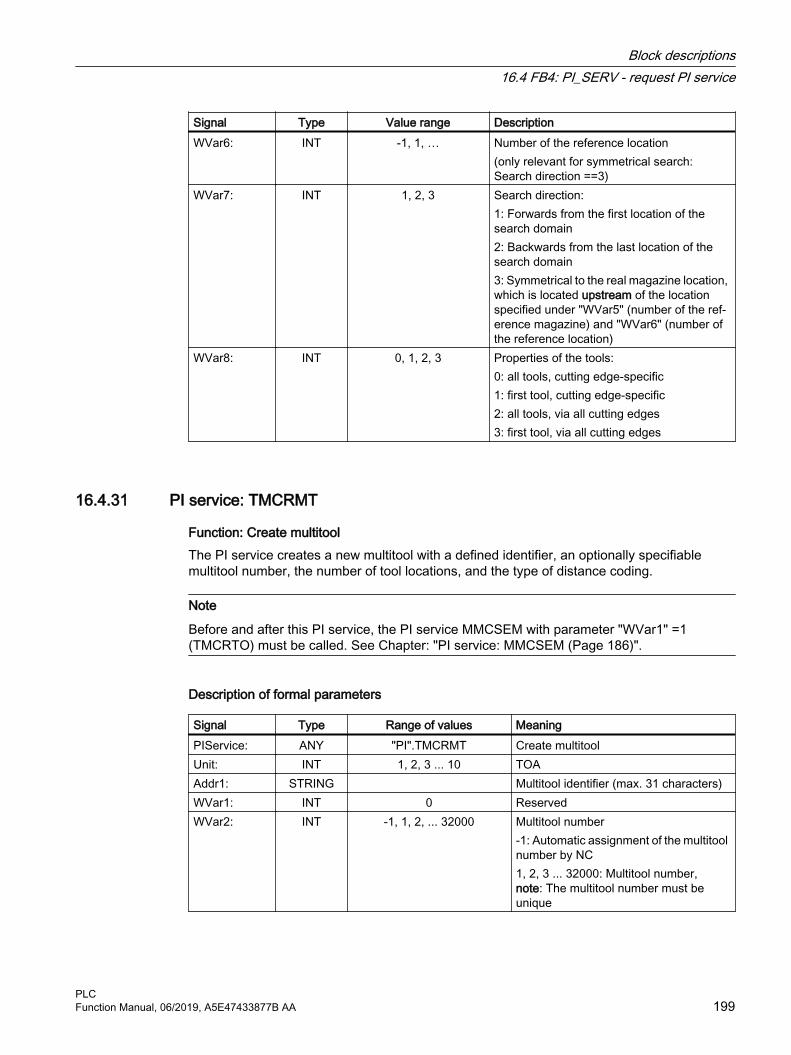
Signal Type Value range DescriptionWVar6: INT -1, 1, … Number of the reference location
(only relevant for symmetrical search: Search direction ==3)
WVar7: INT 1, 2, 3 Search direction:1: Forwards from the first location of the search domain2: Backwards from the last location of the search domain3: Symmetrical to the real magazine location, which is located upstream of the location specified under "WVar5" (number of the ref‐erence magazine) and "WVar6" (number of the reference location)
WVar8: INT 0, 1, 2, 3 Properties of the tools:0: all tools, cutting edge-specific1: first tool, cutting edge-specific2: all tools, via all cutting edges3: first tool, via all cutting edges
16.4.31 PI service: TMCRMT
Function: Create multitool The PI service creates a new multitool with a defined identifier, an optionally specifiable multitool number, the number of tool locations, and the type of distance coding.
Note
Before and after this PI service, the PI service MMCSEM with parameter "WVar1" =1 (TMCRTO) must be called. See Chapter: "PI service: MMCSEM (Page 186)".
Description of formal parameters
Signal Type Range of values MeaningPIService: ANY "PI".TMCRMT Create multitoolUnit: INT 1, 2, 3 ... 10 TOAAddr1: STRING Multitool identifier (max. 31 characters)WVar1: INT 0 ReservedWVar2: INT -1, 1, 2, ... 32000 Multitool number
-1: Automatic assignment of the multitool number by NC1, 2, 3 ... 32000: Multitool number, note: The multitool number must be unique
Block descriptions16.4 FB4: PI_SERV - request PI service
PLCFunction Manual, 06/2019, A5E47433877B AA 199
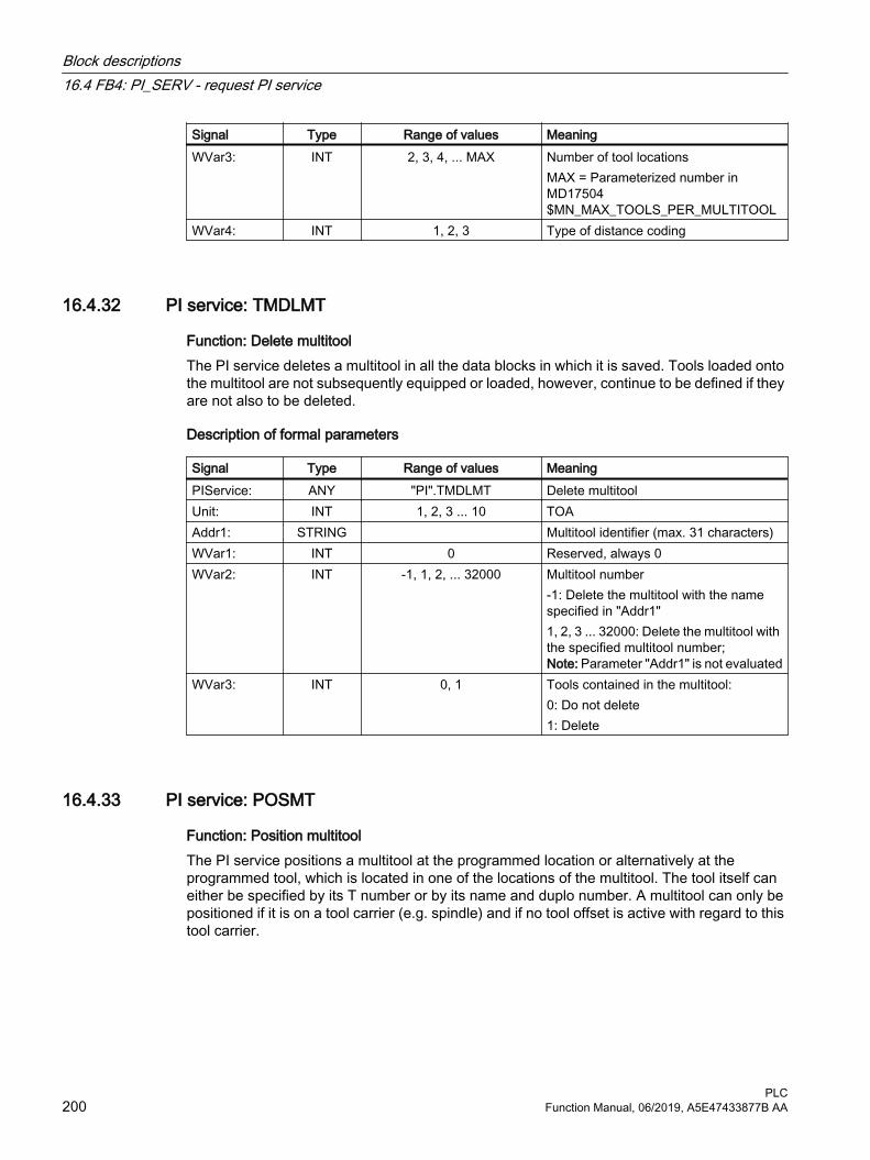
Signal Type Range of values MeaningWVar3: INT 2, 3, 4, ... MAX
Number of tool locationsMAX = Parameterized number in MD17504 $MN_MAX_TOOLS_PER_MULTITOOL
WVar4: INT 1, 2, 3 Type of distance coding
16.4.32 PI service: TMDLMT
Function: Delete multitoolThe PI service deletes a multitool in all the data blocks in which it is saved. Tools loaded onto the multitool are not subsequently equipped or loaded, however, continue to be defined if they are not also to be deleted.
Description of formal parameters
Signal Type Range of values MeaningPIService: ANY "PI".TMDLMT Delete multitoolUnit: INT 1, 2, 3 ... 10 TOAAddr1: STRING Multitool identifier (max. 31 characters)WVar1: INT 0 Reserved, always 0WVar2: INT -1, 1, 2, ... 32000 Multitool number
-1: Delete the multitool with the name specified in "Addr1"1, 2, 3 ... 32000: Delete the multitool with the specified multitool number; Note: Parameter "Addr1" is not evaluated
WVar3: INT 0, 1 Tools contained in the multitool:0: Do not delete1: Delete
16.4.33 PI service: POSMT
Function: Position multitoolThe PI service positions a multitool at the programmed location or alternatively at the programmed tool, which is located in one of the locations of the multitool. The tool itself can either be specified by its T number or by its name and duplo number. A multitool can only be positioned if it is on a tool carrier (e.g. spindle) and if no tool offset is active with regard to this tool carrier.
Block descriptions16.4 FB4: PI_SERV - request PI service
PLC200 Function Manual, 06/2019, A5E47433877B AA

Position specificationThe position specification can be specified as one of three variants:
No.
Addr1 WVar1 WVar2 WVar3 WVar4
1 Empty string Number of the tool carrier
Tool number -1 -1
2 Tool name Number of the tool carrier
-1 Duplo number -1
3 Empty string Number of the tool carrier
-1 -1 Multitool location number
Description of formal parameters
Signal Type Range of values MeaningPIService: ANY "PI".POSMT Position multitoolUnit: INT 1, 2, 3 ... 10 TOAAddr1: STRING Tool name of the tool to be positioned in
the multitool (max. 31 characters)WVar1: INT 1, 2, 3, ... Number of the tool carrierWVar2: INT -1, 1, 2, 3, ... 32000 Tool number (T number) of the tool to be
positioned in the multitool1, 2, 3, ... 32000: Tool number-1: "Addr1" (tool name) and "WVar3" (du‐plo number) are used
WVar3: INT -1, 1, 2, 3, ... 32000 Duplo number of the tool to be positioned in the multitool1, 2, 3, ... 32000: Duplo number-1: "WVar2" (T number) is used
WVar4: INT -1, 1, 2, 3, ... Multitool location number of the tool car‐rier location at which the system should be positioned-1: "WVar2" or "Addr1" and "WVar3" are used
16.4.34 PI service: FDPLMT
Function: Searching for or checking an empty location within the multitoolThe PI service searches for a free tool location in a multitool to hold the specified tool or to check whether the specified tool location in the multitool is free to hold the specified tool. The tool can be specified by the T number or the identifier and the duplo number.
Note
Before and after this PI service, the PI service MMCSEM with parameter "WVar1" = 2 (TMFDPL) must be called. See Chapter "PI service: MMCSEM (Page 186)".
Block descriptions16.4 FB4: PI_SERV - request PI service
PLCFunction Manual, 06/2019, A5E47433877B AA 201

Position specificationThe tool to be positioned in the multitool can be specified as one of the following variants:
● "Addr1" = <Tool name>, "WVar1" = -1 and "WVar2" = <Duplo number>
● "Addr1" = <Empty string>, "WVar1" = <Tool number> and "WVar2" = -1
The position specification can be assigned via:
● "WVar4" = <Multitool location number>
Description of formal parameters
Signal Type Range of values MeaningPIService: ANY "PI".FDPLMT Search/check an empty tool location
within a multitoolUnit: INT 1, 2, 3 ... 10 TOAAddr1: STRING Tool name of the tool to be positioned in
the multitool (max. 31 characters)WVar1: INT -1, 1, 2, 3, ... 32000 Tool number (T number) of the tool to be
positioned in the multitool-1: "Addr1" (tool name) and "WVar2" (du‐plo number) are used.1, 2, 3 ... 32000: Tool number
WVar2: INT -1, 1, 2, 3, ... 32000 Duplo number of the tool to be positioned in the multitool1, 2, 3, ... 32000: Duplo number-1: "WVar1" (T number) is used
WVar3: INT -1, 1, 2, 3, ... 32000 Number of the multitool1, 2, 3, ... 32000: Number of the multitool-1: Search across all multitools for an empty location or check across all multi‐tools whether in one of them the speci‐fied tool location is free to hold the tool.
WVar4: INT -1, 1, 2, 3, ... Multitool location number of the tool lo‐cation at which the system should be positioned>0: Multitool location number -1: Search for any empty tool location within the multitool
16.5 FB5: GETGUD - read GUD variable
Function The function block FB5 "GETGUD" is used for reading global user data (GUD) in the NC or channel area.
Block descriptions16.5 FB5: GETGUD - read GUD variable
PLC202 Function Manual, 06/2019, A5E47433877B AA

Request for reading NC variablesCall of FB5 with positive edge change, parameter "Req" = 0 → 1
Parameter "Addr": The pointer to the name of the GUD variables, symbolically with "<Data block>".<Variable name>
Parameters "Area", "Unit", "Index1", and "Index2": Additional information for addressing the variables
When the parameter "CnvtToken" is activated, the user receives a token (variable pointer) for the GUD variable to be read. Using this, the GUD variables can then be read or written via FB2 and FB3 with parameter "Addr1" ... "Addr8" = "<Token>". Addressing by means of a token is mandatory for writing GUD variables. If the token is used to address GUD variable arrays, the parameter "Line1" ... "Line8" = "<array index>" of the FB2/FB3 must also be provided with values.
To read a GUD variable of the DOUBLE type without adapting the format, an ANY pointer of the REAL2 type must be specified in the target area. E.g. P#M100.0 REAL 2. The value of the GUD variables of the DOUBLE type is then adopted in the PLC data area as a 64-bit floating point number.
Completion of the read requestRead request successfully completed: Parameter "Done" == 1.
Read request completed with error:"Parameter "Error" == 1, error cause in parameter "State"
Prerequisites● Release of the NC/PLC communication by OB100, FB1 parameter "NCKomm" = 1
● For the data block that will contain the string with the name of the GUD variable, the S7 Symbol Editor must be used to assign a symbol in the S7 symbol table of the S7 project (cf. call example 1 below: DB_GUDVAR). In the data block, a string of suitable length must be created to contain the name of the GUD variable (cf. call example 1 below: "DB_GUDVAR".GUDVar1). This symbol is then passed on to parameter "Addr" of FB5, e.g. Addr := "DB_GUDVAR".GUDVar1. If the token for the GUD variable is required for the following calls of the FB2/FB3, the 10-byte token structure must be created in a DB, e.g. the same DB (cf. call example 1 below: "DB_GUDVAR".GUDVar1Token). This structure is specified in parameter VarToken of the FB5, cf. call example 1 below: FB5, VarToken := "DB_GUDVAR".GUDVar1Token. This token is then specified in parameters "Addr1" … "Addr8" when FB2/FB3 is called, cf. call example 1 below: FB3, Addr1 := "GUDVar1Token".
General conditions● FB5 has multi-instance capability.
● Every call of FB5 must be assigned a separate instance DB from the user area.
● Reading of a GUD variable (FB5 call with Req = 1) is only permitted in the cyclic part of the PLC basic program (OB1). If the job is not started (FB5 call with Req = 0), the parameters can also be written in the start-up part of the PLC basic program (OB100). The job can then be executed using the already written parameters in the cyclic part of the PLC basic program (OB1) by calling FB5 with Req = 1.
● Only capital letters may be used for the names of GUD variables.
● Reading of a GUD variable generally extends over several PLC cycles.
Block descriptions16.5 FB5: GETGUD - read GUD variable
PLCFunction Manual, 06/2019, A5E47433877B AA 203

Note
Error caseWhen variables from different channels are read, the following feedback message is output:● "Error" == TRUE● "State" == W#16#02
Note
To read a variable of the DOUBLE type from NC without adapting the format, an ANY pointer of the REAL2 type must be specified in the target area (e.g.: P#M100.0 REAL 2). If the basic program recognizes REAL 2 as the target type when reading a variable of the DOUBLE type, the data is applied to the PLC data area as a 64-bit floating-point number.
Declaration of the function
FUNCTION_BLOCK FB5 //Server name KNOW_HOW_PROTECT VERSION : 3.0VAR_INPUT Req : BOOL; Addr: ANY; // Variable name Area BYTE ; //Area: NCK = 0, channel = 2 Unit : BYTE ; Index1: INT; // Array index 1 Index2: INT; // Array index 2 CnvtToken: BOOL; // Conversion into 10-byte token VarToken ANY; // Struct with 10 bytes for the variable tokenEND_VAR VAR_OUTPUT Error : BOOL; Done : BOOL; State : WORD; END_VAR VAR_IN_OUT RD: ANY; END_VAR BEGINEND_FUNCTION_BLOCK
Block descriptions16.5 FB5: GETGUD - read GUD variable
PLC204 Function Manual, 06/2019, A5E47433877B AA

Description of formal parameters
Signal Type
Type Value range Description
Req: I BOOL Job start with positive signal edgeAddr: I ANY "<DBName>".<Var‐
Name>Variable name in a variable of the type STRING
Area: I BYTE 0, 2 Range:0: NC2: Channel
Unit: I BYTE 1, 2, 3 ... 10 Area == NC: Unit:=1Area == Channel: Channel number
Index1: I INT 0, 1, 2, ... < max. Array in‐dex>
Array index 1For variables without array index: In‐dex1 = 0
Index2: I INT 0, 1, 2, ... < max. Array in‐dex>
Array index 2For variables without 2nd array index: Index2 = 0
CnvtToken: I BOOL 0 (FALSE), 1 (TRUE) Activate generation of a 10 byte varia‐ble token
VarToken: I ANY "<DBName>".<Var‐Name>
Address of a 10byte token (see exam‐ple)
Error: O BOOL 0 (FALSE), 1 (TRUE) Negative acknowledgement of job or execution of job impossible
Done: O BOOL 0 (FALSE), 1 (TRUE) Job successfully executedState: O WORD --- See paragraph "Error identifiers"RD: I/O ANY P#Mm.n BYTE x ...
P#DBnr.dbxm.n BYTE xTarget area for read data
Error identifiers
State Description NoteWORD
H 1)WORD L
0 1 Access error 0 2 Error in job Incorrect compilation of Var. in a job0 3 Negative acknowledgement,
job not executableInternal error, try: NC RESET
0 4 Data areas or data types do not tally
Check data to beread in RD
1 4 Insufficient local user memo‐ry available
read variable is longer than specified in RD
0 6 FIFO full Job must be repeated,since queue is full
0 7 Option not set BP parameter "NCKomm" is not set0 8 Incorrect target area (SD) RD may not be local data0 9 Transmission occupied Job must be repeated
Block descriptions16.5 FB5: GETGUD - read GUD variable
PLCFunction Manual, 06/2019, A5E47433877B AA 205

State Description NoteWORD
H 1)WORD L
0 10 Error in addressing Unit contains value 00 11 Address of variable invalid Check addr (or variable name), area, unit
1 - 8 13 ANY data reference incorrect String/NcVar data required has not been par‐ameterized
0 15 String more than 32 charac‐ters
GUD variable name too long
1) High byte > 0 ⇒ Number of the variable in which the error occurred
Configuration stepsTo be able to read a GUD variable, its name must be stored in a string variable. The data block with this string variable must be defined in the symbol table so that the "Addr" parameter can be assigned symbolically for FB GETGUD. A structure variable can be defined optionally in any data area of the PLC to receive the variable pointer (see specification in following example).
Pulse diagram
① User: Set request, Req = 0 → 1② FB5 successfully completed, Done = 1
User: Reset request, IF Done == 1 THEN Req = 0③ User: IF Done == 1 THEN reset request: 1 → 0④ FB5 reset job confirmation, Done = 0⑤ User: IF Done == 0 AND Error == 0 THEN reset request Req = 1 → 0 not permissible⑥ FB5 completed with errors, Error = 1
User: Reset request, IF Done == 1 OR Error == 1 THEN Req = 0, possible further error handling
Call example 1Read a GUD variable from channel 1:
● Name "GUDVAR1"
● Type: INTEGER
Block descriptions16.5 FB5: GETGUD - read GUD variable
PLC206 Function Manual, 06/2019, A5E47433877B AA

Conversion to a 10 byte variable pointer. See table "Assignment of the data types" in Chapter "FB2: GET - read NC variable (Page 157)"
Reading the GUD variables: FB5 with instance DB111
// Data block for GUD variableDATA_BLOCK DB_GUDVAR // Assignment in symbol table STRUCT GUDVar1 : STRING[32] := 'GUDVAR1'; // Name is defined by
user GUDVar1Token : STRUCT SYNTAX_ID : BYTE ; area_and_unit : BYTE ; column : WORD; line : WORD; block type : BYTE ; NO. OF LINES : BYTE ; type : BYTE ; length : BYTE ; END_STRUCT; END_STRUCT; BEGIN END_DATA_BLOCK // Unassigned user DB, as instance for FB5DATA_BLOCK DB111 FB5 BEGIN END_DATA_BLOCK // Unassigned user DB, as instance for FB3DATE_BLOCK DB112 FB3 BEGIN END_DATA_BLOCK // Reading of a channel-specific GUD variable from channel 1, with conversion to a variable pointerFunction FC "VariablenCall" : VOIDU I 7.7; // Unassigned machine control panel keyS M 100.0; // Activate req.U M 100.1; // Done completed message
Block descriptions16.5 FB5: GETGUD - read GUD variable
PLCFunction Manual, 06/2019, A5E47433877B AA 207
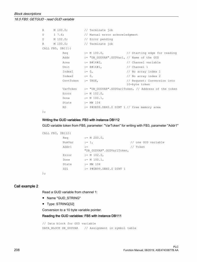
R M 100.0; // Terminate jobU I 7.6; // Manual error acknowledgmentU M 102.0; // Error pendingR M 100.0; // Terminate jobCALL FB5, DB111( Req := M 100.0, // Starting edge for reading Addr := "DB_GUDVAR".GUDVar1, // Name of the GUD Area := B#16#2, // Channel variable Unit := B#16#1, // Channel 1 Index1 := 0, // No array index 1 Index2 := 0, // No array index 2 CnvtToken := TRUE, // Request: Conversion into
10-byte token VarToken := "DB_GUDVAR".GUDVar1Token, // Address of the token Error := M 102.0, Done := M 100.1, State := MW 104 RD := P#DB99.DBX0.0 DINT 1 // free memory area);
Writing the GUD variables: FB3 with instance DB112GUD variable token from FB5, parameter: "VarToken" for writing with FB3, parameter "Addr1"
CALL FB3, DB112( Req := M 200.0, NumVar := 1, // one GUD variable Addr1 :=
"DB_GUDVAR".GUDVar1Token,// Token
Error := M 102.0, Done := M 100.1, State := MW 104 SD1 := P#DB99.DBX0.0 DINT 1);
Call example 2Read a GUD variable from channel 1:
● Name "GUD_STRING"
● Type: STRING[32]
Conversion to a 10 byte variable pointer.
Reading the GUD variables: FB5 with instance DB111
// Data block for GUD variableDATA_BLOCK DB_GUDVAR // Assignment in symbol table
Block descriptions16.5 FB5: GETGUD - read GUD variable
PLC208 Function Manual, 06/2019, A5E47433877B AA

STRUCT GUDVarS : STRING[32] := 'GUD_STRING'; // Name defined by user GUDVarSToken : STRUCT SYNTAX_ID : BYTE ; area_and_unit : BYTE ; column : WORD; line : WORD; block type : BYTE ; NO. OF LINES : BYTE ; type : BYTE ; length : BYTE ; END_STRUCT; string_of_GUD : STRING[30]; // must at least be so long as // the definition of 'GUD_STRING'! new_name : STRING[30] := 'GUD_123';END_STRUCT; BEGIN END_DATA_BLOCK // Unassigned user DB, as instance for FB5DATA_BLOCK DB111 FB5 BEGIN END_DATA_BLOCK // Unassigned user DB, as instance for FB3DATE_BLOCK DB112 FB3 BEGIN END_DATA_BLOCK // Reading of a channel-specific GUD variable from channel 1, with conversion to a variable pointerFunction FC "VariablenCall" : VOIDU I 7.7; // Unassigned machine control panel keyS M 100.0; // Activate req.U M 100.1; // Done completed messageR M 100.0; // Terminate jobU I 7.6; // Manual error acknowledgmentU M 102.0; // Error pending
Block descriptions16.5 FB5: GETGUD - read GUD variable
PLCFunction Manual, 06/2019, A5E47433877B AA 209

R M 100.0; // Terminate jobCALL FB5, DB111( Req := M 100.0, // Starting edge for reading Addr := "DB_GUDVAR".GUDVarS, Area := B#16#2, // Channel variable Unit := B#16#1, // Channel 1 Index1 := 0, // No array index Index2 := 0, // No array index CnvtToken := TRUE, // Request: Conversion into 10-byte
token VarToken := "DB_GUDVAR".GUDVarSToken, // Address of the token Error := M 102.0, Done := M 100.1, State := MW 104 RD := "DB_GUDVAR".string_of_GUD);
Writing the GUD variables: FB3 with instance DB112GUD variable token from FB5, parameter: "VarToken" for writing with FB3, parameter "Addr1"
CALL FB3, DB112( Req := M 200.0, NumVar := 1, // one GUD variable Addr1 := "DB_GUDVAR".GUDVarSToken, // Token Error := M 102.0, Done := M 100.1 State := MW 104 SD1 := "DB_GUDVAR".new_name);
Classification of data typesSee table "Assignment of the data types" in Chapter "FB2: GET - read NC variable (Page 157)"
16.6 FB7: PI_SERV2 - request PI service
Function With the exception of a higher number of "WVar" parameters ("WVar11" - "WVar16"), function block FB7 has the same functionality as function block FB4. It is recommended that function block FB7 be used instead of function block FB4.
For a detailed description, refer to Chapter "FB4: PI_SERV - request PI service (Page 173)".
Block descriptions16.6 FB7: PI_SERV2 - request PI service
PLC210 Function Manual, 06/2019, A5E47433877B AA

Declaration of the function
FUNCTION_BLOCK FB7Var_INPUT Req: BOOL; PIService: ANY; Unit: INT; Addr1: ANY; Addr2: ANY; Addr3: ANY; Addr4: ANY; WVar1: WORD; WVar2: WORD; WVar3: WORD; WVar4: WORD; WVar5: WORD; WVar6: WORD; WVar7: WORD; WVar8: WORD; WVar9: WORD; WVar10: WORD; WVar11: WORD; WVar12: WORD; WVar13: WORD; WVar14: WORD; WVar15: WORD; WVar16: WORD;END_VARVAR_OUTPUT Error : BOOL; Done : BOOL; State : WORD;END_VAR
16.7 FB9: MtoN - operator panel switchover
FunctionThe function block FB9 "MzuN" is used for switching over operating components (MCP/OP), which are connected via a bus system to one or more NCU control modules.
The interface between the individual operating units (operator panels) and the NCU (PLC) is the M : N interface in data block DB19. FB9 uses the signals of these interfaces.
Block descriptions16.7 FB9: MtoN - operator panel switchover
PLCFunction Manual, 06/2019, A5E47433877B AA 211

Apart from initialization, sign-of-life monitoring and error routines, the following basic functions are also performed by the block for control unit switchover:
Tabulated overview of functions:Basic function DescriptionHMI queuing HMI wants to go online with an NCUHMI coming HMI is connecting to an NCUHMI going HMI is disconnecting from an NCUForced break HMI must break connection with an NCUOperating focus changeover to serv‐er mode
Change operating focus from one NCU to the other
Active/passive operating mode: Operator control and monitoring/monitoring onlyMCP switchover As an option, MCP can be switched over with the HMI
Note
The block must be called by the user program. The user must provide an instance DB with any number for this purpose. The call is multi-instance-capable.
Brief description of a few important functionsActive/passive operating mode:
An online HMI can operate in two different modes:
Active mode: Operator can control and monitorPassive mode: Operator can monitor (HMI header only)
After switchover to an NCU, this initially requests active operating mode in the PLC of the online NCU. If two control units are linked online simultaneously to an NCU, one of the two is always in active mode and the other in passive mode. The operator can request active mode on the passive HMI at the press of a button.
MCP switchoverAs an option, an MCP assigned to the HMI can be switched over at the same time. To achieve this, the MCP address must be entered in the "mstt_adress" parameter of the NETNAMES.INI configuration file on the HMI and "MCPEnable" must be set to TRUE. The MCP of the passive HMI is deactivated so that there is only ever one active MCP on an NCU at one time.
Boot conditionIn order to prevent, that for an NCU restart, the previously selected MCP is activated, when calling FB1 in OB100, input parameter "MCP1BusAdr" must be set = 255 (address 1st MCP) and "MCP1Stop" must be set = TRUE (switch off 1st MCP).
Block descriptions16.7 FB9: MtoN - operator panel switchover
PLC212 Function Manual, 06/2019, A5E47433877B AA

ApprovalsWhen one MCP is switched over to another, any active feed or axis enables will be retained.
Note
Keys actuated at the moment of switchover remain operative until the new MCP is activated (by the HMI, which is subsequently activated). The override settings for feedrate and spindle also remain valid. To deactivate actuated keys, the input image of the machine control signals must be switched to nonactuated signal level on a falling edge of DB10.DBX104.0 (MCP 1 ready). The override settings should remain unchanged. Measures for deactivating keys must be implemented in the PLC user program (see example "Override Changeover").
The call is permitted only in cyclic program OB1.
Declaration of the function
FUNCTION_BLOCK FB9VAR_INPUT Ackn: BOOL; // Acknowledge interrupts OPMixedMode: BOOL:= FALSE; // Mixed operation with non-M-to-N-
enabled OP // deactivated ActivEnable: BOOL:=TRUE; // Not supported MCPEnable: BOOL:=TRUE; // Activate MCP switchoverEND_VARVAR_OUTPUT Alarm1: BOOL; // Interrupt: Error in HMI bus address,
bus type! Alarm2: BOOL; // Interrupt: No confirmation HMI 1
offline! Alarm3 : BOOL; // Interrupt: HMI 1 is not going
offline! Alarm4 : BOOL; // Interrupt: No confirmation HMI 2
offline! Alarm5 : BOOL; // Interrupt: HMI 2 is not going
offline! Alarm6 : BOOL; // Interrupt: Queuing HMI is not going
online! Report : BOOL; // Message: Signoflife monitoring ErrorMMC : BOOL; // Error detection HMIEND_VAR
Block descriptions16.7 FB9: MtoN - operator panel switchover
PLCFunction Manual, 06/2019, A5E47433877B AA 213

Description of formal parameters
Signal Type
Type Value range Description
Ackn: I BOOL 0 (FALSE), 1 (TRUE) Acknowledge interruptsOPMixedMode: I BOOL 0 (FALSE), 1 (TRUE) Mixed operation deactivated for OP
without M:N capabilityActivEnable: I BOOL 0 (FALSE), 1 (TRUE) Function is not supported. Operator
panel switchover Interlocking using MMCx_SHIFT_LOCK in DB19
MCPEnable: I BOOL 0 (FALSE), 1 (TRUE) Activate MCP switchover1: MCP is switched over with operator panel.0: MCP is not switched over with oper‐ator panel. This can be used to perma‐nently link an MCP. See also MMCx_MSTT_SHIFT_LOCK in DB19.
Alarm1: O BOOL 0 (FALSE), 1 (TRUE) Interrupt: Error in HMI bus address, bus type!
Alarm2: O BOOL 0 (FALSE), 1 (TRUE) Interrupt: No confirmation HMI 1 off‐line!
Alarm3 : O BOOL 0 (FALSE), 1 (TRUE) Interrupt: HMI 1 is not going offline!Alarm4 : O BOOL 0 (FALSE), 1 (TRUE) Interrupt: No confirmation HMI 2 off‐
line!Alarm5 : O BOOL 0 (FALSE), 1 (TRUE) Interrupt: HMI 2 is not going offline!Alarm6 : O BOOL 0 (FALSE), 1 (TRUE) Interrupt: Queuing HMI is not going
online!Report : O BOOL 0 (FALSE), 1 (TRUE) Message: Sign-of-life monitoring HMIErrorMMC : O BOOL 0 (FALSE), 1 (TRUE) Error detection HMI
Example of calling FB9
CALL FB9, DB109( Ackn := Error_ack, //e.g., MCP RESET OPMixedMode := FALSE, ActivEnable := TRUE, MCPEnable := TRUE); // Enable for MCP switchover
Note
Input parameter “MCPEnable” must be set to TRUE to enable the MCP switchover. The default value of these parameters is set in this way and need not be specially assigned when the function is called.
Block descriptions16.7 FB9: MtoN - operator panel switchover
PLC214 Function Manual, 06/2019, A5E47433877B AA

Interrupts, errorsThe output parameters "Alarm1" to "Alarm6" and "Report" exist as information in the PLC and are output in the event of M:N errors visualized on the HMI by the appearance of alarms 410900 - 410906.
If execution of an HMI function has failed (and an appropriate error message cannot be displayed), status parameter "ErrorMMC" is set to 'logical 1' (e.g., booting error, when no connection is made).
Example of a call for FB (call in the OB100)
CALL "RUN_UP", "gp_par" ( MCPNum := 1, MCP1In := P#I 0.0, MCP1Out := P#Q 0.0, MCP1StatSend := P#Q 8.0, MCP1StatRec := P#Q 12.0, MCP1BusAdr := 255, // address 1st MCP MCP1Timeout := S5T#700MS, MCP1Cycl := S5T#200MS, MCP1Stop := TRUE, // MCP switched off NCCyclTimeout := S5T#200MS, NCRunupTimeout := S5T#50S);
Example: Override switchover
// Auxiliary flags used M100.0, M100.1, M100.2, M100.3//Edge positive of MCP1Ready must check the override//and measures for activation// Initiate MCP block//This example applies to the feedrate override;//The interface and input bytes must be exchanged for spindle override.U DB10.DBX104.0; //MCP1ReadyEN M 100.0; // Edge memory bit 1JCN smth1; S M 100.2; // Set auxiliary memory bit 1R M 100.3; //Reset auxiliary flag 2
// Save override L DB21.DBB4; //Feed override interface T EB28; //Buffer storage (freely input
// or flag byte) wei1:U M 100.2; //Switchover takes place
Block descriptions16.7 FB9: MtoN - operator panel switchover
PLCFunction Manual, 06/2019, A5E47433877B AA 215

O DB10.DBX104.0; //MCP1ReadyJCN smth2; U DB10.DBX104.0; //MCP1ReadyFP M 100.1; // Edge memory bit 2JC smth2;U M 100.2; //Switchover takes placeR M 100.2; //Reset auxiliary flag 1JC smth2;U M 100.3; //Comparison has taken placeSPB MCP; //Call MCP program// Route the stored override to the interface of the switched MCP// until the override values match L EB28; //Buffer storage open T DB21.DBB4; //Route override interface L EB3; //Override input byte for feed <>i; //Match?JC smth2; //No, jumpS M 100.3; //Yes, set auxiliary flag 2// When override values match, call the MCP program againMCP: CALL "MCP_IFM"( //FC19 BAGNo := B#16#1, ChanNo := B#16#1, SpindleIFNo := B#16#0, FeedHold := M 101.0, SpindleHold := M 101.1);wei2: NOP 0:
16.8 FB10: Safety relay (SI relay)
Function The SPL function block FB10 "Safety relay" for "Safety Integrated" is the PLC equivalent of the NC function of the same name. The standard SPL "Safety relay" block is designed to support the implementation of an emergency stop function with safe programmable logic. However, it can also be used to implement other similar safety functions, e.g., control of a protective door.
The function contains 3 input parameters ("In1", "In2", "In3"). On switchover of one of these parameters to the value 0, the output "Out0" is deactivated without delay and outputs "Out1", "Out2", and "Out3" are deactivated via the parameterized timer values (parameters "TimeValue1", "TimeValue2", "TimeValue3"). The outputs are activated again without delay if inputs "In1" to "In3" take on value 1 and a positive edge change is detected at one of the acknowledgment inputs "Ack1", "Ack2".
Call bit memoryTo bring the outputs to their basic setting (values = 0) after booting, the parameter "FirstRun" must be configured as follows. The parameter "FirstRun" must be switched to the value TRUE
Block descriptions16.8 FB10: Safety relay (SI relay)
PLC216 Function Manual, 06/2019, A5E47433877B AA

via a retentive data (memory bit, bit in data block) on the 1st run after control booting. This data can be preset, e.g., in OB100. The parameter "FirstRun" is reset to FALSE when FB10 is executed for the first time. Separate data must be used for parameter "FirstRun" for each call with its own instance.
General conditions● FB10 has multi-instance capability
● After the start of the SPL program, FB10 is called once per SI relay in the cyclic part of the PLC basic program (OB1).
● Every call of FB10 must be assigned a separate instance DB from the user area.
Simplified block diagram in CSFThe figure below shows only one acknowledgment input "Ack1" and one delayed deactivation output "Out1". The circuit for "Ack2" and the other delayed outputs are identical. The parameter "FirstRun" is also missing in the function diagram. The mode of operation is described above.
Declaration of the function
FUNCTION_BLOCK FB10VAR_INPUT In1 : BOOL;
Block descriptions16.8 FB10: Safety relay (SI relay)
PLCFunction Manual, 06/2019, A5E47433877B AA 217

In2 : BOOL; In3 : BOOL; Ackn1 : BOOL; Ackn2 : BOOL; TimeValue1 : TIME; TimeValue2 : TIME; TimeValue3 : TIME; END_VARVAR_OUTPUT Out0 : BOOL; Out1 : BOOL; Out2 : BOOL; Out3 : BOOL; END_VARVAR_INOUT FirstRun: BOOL; END_VAR
Description of formal parameters
Parameter Type
Type Value range Description
In1: I BOOL 0 (FALSE), 1 (TRUE) Input 1In2: I BOOL 0 (FALSE), 1 (TRUE) Input 2In3: I BOOL 0 (FALSE), 1 (TRUE) Input 3Ackn1 : I BOOL 0 (FALSE), 1 (TRUE) Acknowledgment input 1Ackn2 : I BOOL 0 (FALSE), 1 (TRUE) Acknowledgment input 2TimeValue1 : I S5TIME Time value 1 for OFF delayTimeValue2 : I S5TIME Time value 2 for OFF delayTimeValue3 : I S5TIME Time value 3 for OFF delayOut0 : O BOOL 0 (FALSE), 1 (TRUE) Output, instantaneous (no delay)Out1 : O BOOL 0 (FALSE), 1 (TRUE) Output, delayed by TimeValue1Out2 : O BOOL 0 (FALSE), 1 (TRUE) Output, delayed by TimeValue2Out3 : O BOOL 0 (FALSE), 1 (TRUE) Output, delayed by TimeValue3FirstRun: I/O BOOL 0 (FALSE), 1 (TRUE) Call bit memory
16.9 FB11: Brake test
FunctionThe braking operation check should be used for all axes, which must be prevented from moving in an uncontrolled manner by a holding brake. "Vertical axes" are the main application.
Block descriptions16.9 FB11: Brake test
PLC218 Function Manual, 06/2019, A5E47433877B AA

The machine manufacturer can use the PLC user program to regularly close the brake at a suitable instant (e.g. every 8 hours) and have the drive exert torque/force in addition to the weight of the axis. In errorfree operation, the brake can produce the necessary braking torque/braking force. The axis will hardly move during this.
When an error occurs, the actual position value exits the parameterizable monitoring window. The position controller prevents sagging of the axis. The function test of the brake mechanical system is negatively acknowledged.
Further informationA detailed description of the parameterization of the NC and drive within the framework of the "Safety Integrated" function can be found in:
Function Manual for Safety Integrated
Starts the brake test The brake test must always be started when the axis is at a standstill. For the entire duration of the brake test, the enable signals of the parameterized axis must be set to enable (e.g. controller inhibit, feed enable). Furthermore, the signal at the axis/spindle DB31, ... .DBX28.7 (PLC-controlled axis) is to be set to status 1 by the user program for the complete duration of the test.
Before activating the NC/PLC interfaces DB31, ... .DBX28.7 (axis controlled from the PLC program), the axis must be switched as "neutral axis". For example, DB31, ... .DBX8.0 - 8.3 (assign NC axis channel) can be set to channel 0 - and DB31, ... .DBX8.4 can be set (activation signal when this byte changes).
The return message:
● about the current status can be queried in DB31, ... DBB68.
● the Nc via the signal DB31, ... .DBX63.1 (PLC controls axis) is to be awaited before the block is started. The direction in which the drive must produce its torque/force is specified by the PLC in the form of a "traversing motion" (e.g., via FC18).
The axis must be able to reach the destination of this movement without risk of collision if the brake is unable to produce the necessary torque/force.
NoteNote on FC18
If FC18 is called over the further course of the user program for the same axis, the calls must be mutually interlocked. For example, this can be achieved via a common call of this function with an interlocked common data interface for the FC18 parameters. A 2nd option is to call the FC18 repeatedly, in which case the inactive FC18 will not be processed by the program. A multiple-use interlock must be provided.
Structure of a brake test
Step Expected feedback Monitoring time value1 Start brake test DBX71.0 = 1 TV_BTactiv2 Close brake Bclosed = 1 TV_Bclose3 Output traversing command DBX64.6 OR DBX64.7 TV_FeedCommand
Block descriptions16.9 FB11: Brake test
PLCFunction Manual, 06/2019, A5E47433877B AA 219

Step Expected feedback Monitoring time value4 Issue test travel command DBX62.5 = 1 TV_FXSreached5 Wait for the holding time DBX62.5 = 1 TV_FXShold6 Deselect brake test / open brake DBX71.0 = 0 TV_BTactiv7 Output test ok --- ---
Boundary conditions● FB2 has multi-instance capability.
● Every call of FB11 must be assigned a separate instance DB from the user area.
Declaration of the function
Function_BLOCK FB11VAR_INPUT Start BOOL; Ackn : BOOL; Bclosed : BOOL; Axis : INT; TimerNo : TIMER ; TV_BTactiv : S5TIME ; TV_Bclose : S5TIM; TV_FeedCommand : S5TIME ; TV_FXSreached : S5TIME ; TV_FXShold : S5TIME ; END_VARVAR_OUTPUT CloseBrake : BOOL; MoveAxis : BOOL; Done : BOOL; Error : BOOL; State : BYTE ; END_VAR
Description of formal parameters
Signal Type Type MeaningStart I BOOL Starts the brake testAckn I BOOL Acknowledge faultBclosed I BOOL Checkback input whether Close Brake is activated
(singlechannel - PLC)Axis I INT Axis number of axis to be testedTimerNo I TIMER Timer from user program
Block descriptions16.9 FB11: Brake test
PLC220 Function Manual, 06/2019, A5E47433877B AA

Signal Type Type MeaningTV_BTactiv I S5TIME Monitoring time value → brake test active, check of
axis signal DBX71.0TV_Bclose I S5TIME Monitoring time value → close brake. Check of input
signal Bclosed after output CloseBrake has been setTV_FeedCommand I S5TIME Monitoring time value → Travel command given
Check travel command after MoveAxis has been setTV_FXSreched I S5TIME Monitoring time value → fixed stop reachedTV_FXShold I S5TIME Monitoring time value → test brakeCloseBrake O BOOL Request, close brakeMoveAxis O BOOL Request, initiate traversing motionDone O BOOL Test successfully completedError O BOOL An error occurredState O BYTE See paragraph "Error identifiers"
Fault IDs
State Meaning0 No error1 Start conditions not fulfilled, e.g. the axis is not in closed-loop control / brake closed / axis
inhibited2 No NC checkback in "Brake test active" signal on selection of brake test 3 No "Brake applied" checkback by input signal Bclosed4 No travel command output (e.g., axis motion has not been started)5 Fixed end stop will not be reached → axis RESET was initiated.6 Traversing inhibit/Approach too slow → fixed stop cannot be reached. TV FXSreached mon‐
itoring timeout.7 Brake is not holding at all (the end position is reached)/approach speed is too high8 Brake opens during the holding time9 Error when deselecting the brake test10 Internal error 11 "PLC-controlled axis" signal not enabled in the user program
Example of calling FB11:
UN M 111.1; //Request to close brake, Z axis of FB = O 85.0; //Brake control, Z axis AUF Axis3"; //Brake test, Z axis O I 73.0; //Brake test trigger, Z axis O M 110.7; //Brake test running FP M 110.0; UN M 111.4; //Error has occurred S M 110.7; //Brake test running S M 110.6; //Next step
Block descriptions16.9 FB11: Brake test
PLCFunction Manual, 06/2019, A5E47433877B AA 221

JCN m001 L DBB 68; AW W#16#F; T MB 115; //flag channel state L B#16#10 T DBB 8; //Request neutral axis m001: U DBX 68.6; //Checkback signal, axis is neutral U M 110.6; FP M 110.1; R M 110.6; S M 110.5; //Next step S DBX 28.7; //Request PLC-monitored axis U DBX 63.1; //Checkback signal, axis monitored by PLC U M 110.5; FP M 110.2; R M 110.5; S M 111.0; //Start brake test for FB CALL FB11, DB211 (//brake test block Start :=M 111.0, //Start brake test Ackn := I 3.7, //Acknowledge error with RESET
key Bclosed := I 54.0, //Return message close brakes
//controlled Axis := 3, //Axis number of axis to be
tested//Z axis
TimerNo := T 110, //Timer number TV_BTactiv := S5T#200MS, //Monitoring time value:
//Brake test active DBX71.0 TV_Bclose := S5T#1S, //Monitoring time value:
//Brake closed TV_FeedCommand := S5T#1S, //Monitoring time value:
//Traversing command output TV_FXSreache := S5T#1S, //Monitoring time value:
//Fixed stop reached TV_FXShold := S5T#2S, //Monitoring time value:
//Brake test time CloseBrake :=M 111.1, //Request to close brake MoveAxis :=M 111.2, Initiate //Request traversing
motion // Done :=M 111.3, //Test successfully completed Error :=M 111.4, //Error has occurred State := MB 112); //Error status
Block descriptions16.9 FB11: Brake test
PLC222 Function Manual, 06/2019, A5E47433877B AA

AUF "Axis3";
//Brake test, Z axis
U M 111.2; //Moveaxis FP M 111.5; //FC18 Start S M 111.7; //Start FC18 O M 111.3; //Test successfully completed O M 111.4; //Error has occurred FP M 110.3; R DBX 28.7; //Request, PLC-monitored axis UN DBX 63.1; //Checkback signal, axis monitored by PLC U M 111.0; //Start brake test for FB U M 110.7; //Brake test running FP M 110.4; R M 111.0; //Start brake test for FB R M 110.7; //Brake test running //optional begin JCN m002; L MB 115; //old channel status OW W#16#10
;
T DBB 8; //Request channel axism002: NOP 0; //optional end CALL "SpinCtrl" (//Traverse Z axis Start :=M 111.2, //Start traversing motion Stop := FALSE, Funct := B#16#5, //Mode: Axis mode Mode := B#16#1, //Procedure: Incremental AxisNo := 3, //Axis number of axis to be
traversed //axis Z-axis
Pos := -5.000000e+000, //Traversing distance: Minus 5 mm FRate := 1.000000e+003, //Feedrate: 1000 mm/min InPos :=M 113.0, //Position reached Error :=M 113.1, //Error has occurred State := MB 114); //Error status AUF "Axis3"
;//Brake test, Z axis
U M 113.0; //Position reached
Block descriptions16.9 FB11: Brake test
PLCFunction Manual, 06/2019, A5E47433877B AA 223

O M 113.1; //Error has occurred FP M 113.2; R M 111.7; //Start FC18
16.10 FB29: Signal recorder and data trigger diagnostics
Function
Signal recorderFB29 "Diagnostics" allows various diagnostic routines to be performed on the PLC user program. A diagnostic routine logs signal states and signal changes. In this diagnostic routine, function number 1 is assigned to the "Func" parameter. Up to 8 signals of the parameters "Signal_1" to "Signal_8" are recorded in a ring buffer each time one of the signals changes. The current information of parameters "Var1" as BYTE value, and "Var2" and "Var3" as INTEGER values are also stored in the ring buffer.
The number of past OB1 cycles is also stored in the buffer as additional information. This information enables the graphical evaluation of signals and values in OB1 cycle grid.
Call ruleFirst call of FB29 in OB1 cycle: Parameter "NewCycle" = 1
All other calls of FB29 in the same OB1 cycle: Parameter "NewCycle" = 0
Ring bufferThe ring buffer, which must be defined by the user, must have an ARRAY structure specified as in the source code. The array can have any number of elements. A size of 250 elements is recommended. The "ClearBuf" parameter is used to clear the ring buffer and set the "BufAddr" pointer to the start. The instance DB related to the FB29 is a DB from the user area and is to be transferred to the FB Diagnostics with the parameter "BufDB".
Data triggerThe data trigger function is intended to allow triggering on specific values (or bits) at any permissible memory cell. The cell to be triggered is "rounded" with a bit mask ("AndMask" parameter) before the "TestVal" parameter is compared in the diagnostic block.
Note
The source code for the function is available in the source container of the basic-program library under the name "Diagnose.awl". The instance DB and the ring buffer DB are also defined in this source block. The function call is also described in the function. The DB numbers and the call must be modified.
Block descriptions16.10 FB29: Signal recorder and data trigger diagnostics
PLC224 Function Manual, 06/2019, A5E47433877B AA

Declaration of the function
FUNCTION_BLOCK FB29VAR_INPUTFunc : INT; Signal_1 : BOOL; Signal_2 : BOOL; Signal_3 : BOOL; Signal_4 : BOOL; Signal_5 : BOOL; Signal_6 : BOOL; Signal_7 : BOOL; Signal_8 : BOOL; NewCycle : BOOL; Var1 : BYTE ; Var2 : INT; Var3 : INT; BufDB : INT; ClearBuf : BOOL; DataAdr : POINTER; TestVal : WORD; AndMask : WORD; END_VARVAR_OUTPUT TestIsTrue : BOOL; END_VARVAR_IN_OUT BufAddr : INT; END_VAR
Structure of the ring buffer
TITLE = //Ring buffer DB for FB29VERSION : 1.0 STRUCT Field: ARRAY [0 .. 249 ] OF
STRUCT//can be any size of this struct
Cycle : INT; //Delta cycle to last storage in buffer Signal_1 : BOOL; //Signal names same as FB29 Signal_2 : BOOL; Signal_3 : BOOL;
Block descriptions16.10 FB29: Signal recorder and data trigger diagnostics
PLCFunction Manual, 06/2019, A5E47433877B AA 225

Signal_4 : BOOL; Signal_5 : BOOL; Signal_6 : BOOL; Signal_7 : BOOL; Signal_8 : BOOL; Var1 : BYTE ; Var2 : WORD; Var3 : WORD; END_STRUCT;END_STRUCT;BEGINEND_DATA_BLOCK
Description of formal parameters
Signal Type Type Value range DescriptionFunc: I INT 0, 1, 2 Function
0: Switch off1: Signal recorder2: Data trigger
Parameters for function 1Signal_1 ... Signal_8:
I BOOL 0 (FALSE), 1 (TRUE)
Bit signals checked for change
NewCycle: I BOOL 0 (FALSE), 1 (TRUE)
See paragraph "Function" above
Var1 : I BYTE Additional valueVar2 : I INT Additional valueVar3 : I INT Additional valueBufDB: I INT Ring buffer DB no.ClearBuf: I BOOL 0 (FALSE), 1
(TRUE)Delete ring buffer DB and reset pointer Bu‐fAddr
BufAddr: I/O INT Target area for read dataParameters for function 2DataAdr: I POINTER Pointer to word to be testedTestVal: I WORD Comparison valueAndMask: I WORD See paragraph "Function" aboveTestIsTrue: O BOOL 0 (FALSE), 1
(TRUE)Result of comparison
Configuration steps● Select function of diagnostics block.
● Define suitable data for the recording as signal recorder or data triggering.
● Find a suitable point or points in the user program for calling the diagnostics FB.
Block descriptions16.10 FB29: Signal recorder and data trigger diagnostics
PLC226 Function Manual, 06/2019, A5E47433877B AA

● Create a data block for the ring buffer, see call example.
● Call the diagnostics FB with parameters in the user program.
In function 1, it is advisable to clear the ring buffer with the "ClearBuf" parameter. When the recording phase with function 1 is completed, read out the ring buffer DB in STEP7 with the function "opening the data block in the data view". The content of the ring buffer DB can now be analyzed.
Call example
FUNCTION FC99: VOIDTITLE =VERSION : 0.0 BEGINNETWORKTITLE = NETWORK CALL FB29, DB80(Func := 1, Signal_1 :=M 100.0, Signal_2 :=M 100.1, Signal_3 :=M 100.2, Signal_4 :=M 100.3, Signal_5 :=M 10.4, Signal_6 :=M 100.5, Signal_7 :=M 100.6, Signal_8 :=M 100.7, NewCycle := TRUE, Var1 := MB 100, BufDB := 81, ClearBuf :=M 50.0);END_FUNCTION
16.11 FC2 : GP_HP - basic program, cyclic section
FunctionThe NC/PLC interface is processed by the basic program in cyclic mode (OB1). To keep the runtime to a minimum, only the control and state signals are cyclically transferred. The transfer of auxiliary and G commands is processed only on request from the NC.
Furthermore, the data for handwheel selection, modes, and other operating signals are transferred from the operator panel (HMI) to the NC/PLC interface so that the modes support the selection from the MCP or HMI as required.
Block descriptions16.11 FC2 : GP_HP - basic program, cyclic section
PLCFunction Manual, 06/2019, A5E47433877B AA 227

The transfer of HMI signals to the NC/PLC interface can be deactivated by setting the value of the parameter "MMCToIF" to "FALSE" in FB1 (DB7).
Handwheel selection signals Requirement: FB1, parameter "HWheelMMC == "TRUE"
The handwheel selection signals from the HMI are decoded and activated in the respective machine or geometry axis of the respective handwheel.
Declaration
FUNCTION FC2: VOID // No parameters
Call exampleAs far as the time is concerned, the basic program must be executed before the user program. It is, therefore, called first in OB1.
The following example contains the standard declarations for OB1 and the calls for the basic program (FC2), the transfer of the MCP signals (FC19), and the acquisition of error and operational messages (FC10).
ORGANIZATION_BLOCK OB1VAR_TEMP OB1_EV_CLASS : BYTE ; OB1_SCAN_1 : BYTE ; OB1_PRIORITY : BYTE ; OB1_OB_NUMBR : BYTE ; OB1_RESERVED_1 : BYTE ; OB1_RESERVED_2 : BYTE ; OB1_PREV_CYCLE : INT; OB1_MIN_CYCLE : INT; OB1_MAX_CYCLE : INT; OB1_DATE_TIME : DATE_AND_TIME;END_VARBEGINCALL FC2; // Call basic program as 1st FC//INSERT USER PROGRAM HERECALL FC19( //MCP signals to interfaceBAGNo := B#16#1, // Mode group no. 1ChanNo := B#16#1, // Channel no. 1SpindleIFNo := B#16#4, //Spindle interface number = 4
// (Number of the associated machine axis)
FeedHold := m22.0, //Feed stop signal //ModalSpindleHold := db2.dbx151.0); //Spindle stop modal
Block descriptions16.11 FC2 : GP_HP - basic program, cyclic section
PLC228 Function Manual, 06/2019, A5E47433877B AA

//in message DBCALL FC10( // Error and operational messages ToUserIF := TRUE, //Signals transferred from DB2
//to interface Ackn := I6.1); //Acknowledgment of error messages
//via I6.1END_ORGANIZATION_BLOCK
16.12 FC3: GP_PRAL - basic program, interruptdriven section
FunctionBlock-synchronized transfers from the NC to the PLC (auxiliary and G commands) are processed in the alarm-driven part of the basic program. Auxiliary functions are subdivided into normal and highspeed auxiliary functions.
The highspeed functions of an NC block are buffered and the transfer acknowledged to the NC. These are transferred to the application interface at the start of the next OB1 cycle.
Highspeed auxiliary functions programmed immediately one after the other, are not lost for the user program. This is ensured by a mechanism in the basic program.
Normal auxiliary functions are acknowledged to the NC only after one completed cycle duration. This allows the application to issue a read disable to the NC.
The G commands are evaluated immediately and passed to the application interface.
NC process alarmsIf the interrupt is triggered by the NC (possible in each IPO cycle), a bit in the local data of OB40 ("GP_IRFromNCK") is set by the basic program, only when the FB1 parameter "UserIR" is TRUE. This data is not set on other events (process alarms through I/Os). This information makes it possible to branch into the associated interrupt routine in the user program in order to initiate the necessary action.
To be able to implement highspeed, jobdriven processing of the user program for the machine, the following NC functions are available in the interrupt processing routine (OB40 program section) for the PLC user program:
● Selected auxiliary functions
● Tool-change function for tool-management option
● Position reached for positioning axes, indexing axes and spindles with activation via PLC
The functions listed above can or must be evaluated by the user program in OB40 in order to initiate reactions on the machine. As an example, the revolver switching mechanism can be activated when a T command is programmed on a turning machine.
For further details on programming process alarms (time delay, interruptibility, etc.) refer to the corresponding SIMATIC documentation.
Block descriptions16.12 FC3: GP_PRAL - basic program, interruptdriven section
PLCFunction Manual, 06/2019, A5E47433877B AA 229

Auxiliary functionsGenerally, high-speed or acknowledging auxiliary functions are processed with or without interrupt control independently of any assignment.
Basic-program parameters in FB1 can be set to define which auxiliary functions (T, H, DL) must be processed solely on an interruptdriven basis by the user program.
Functions which are not assigned via interrupts are only made available by the cyclic basic program as in earlier versions. The change signals of these functions are available in a PLC cycle.
Even if the selection for the auxiliary function groups (T, H, DL) is made using interrupt control, only one interrupt can be processed by the user program for the selected functions.
A bit is set for a specific channel in the local data "GP_AuxFunction" for the user program (if "GP_AuxFunction[1]" is set, an auxiliary function is available for the 1st channel).
In the related channel-DB the change signal and the function value are available for the user. The request signal of this interrupt-driven function is reset to zero in the cyclic basic program section after the execution of at least one full OB1 cycle (max. approx. two OB1 cycles).
Tool changeWith the tool-management option, the tool-change command for revolver and the tool change in the spindle is supported by an interrupt. The local data bit "GP_TM" in OB40 is set for this purpose. The PLC user program can thus check the tool management DB (DB72 or DB73) for the tool change function and initiate the tool change operation.
Position reachedIn the bit structure, "GP_InPosition" of the local data of OB40 is specific to the machine axis (each bit corresponds to an axis/spindle, e.g. GP_InPosition[5] corresponds to the 5th axis).
If a function has been activated via FC18 (spindle control, positioning axis, indexing axis) for an axis or spindle, the associated "GP_InPosition" bit can be used to implement instantaneous evaluation of the "InPos" signal of the FCs listed above. This feature can be used, for example, to obtain immediate activation of clamps for an indexing axis.
Declaration
FUNCTION FC3: VOID // No parameters
Call exampleAs far as the time is concerned, the basic program must be executed before other alarm-driven user programs. It is, therefore, called first in OB40.
Block descriptions16.12 FC3: GP_PRAL - basic program, interruptdriven section
PLC230 Function Manual, 06/2019, A5E47433877B AA

The following example contains the standard declarations for OB40 and the call for the basic program.
ORGANIZATION_BLOCK OB40VAR_TEMP OB40_EV_CLASS : BYTE ; OB40_STRT_INF : BYTE ; OB40_PRIORITY : BYTE ; OB40_OB_NUMBR : BYTE ; OB40_RESERVED_1 : BYTE ; OB40_MDL_ID : BYTE ; OB40_MDL_ADDR : INT; OB40_POINT_ADDR : DWORD; OB40_DATE_TIME : DATE_AND_TIME; //Assigned to basic programGP_IRFromNCK : BOOL; //Interrupt by NC for userGP_TM : BOOL; //Tool managementGP_InPosition : ARRAY [1..3] OF BOOL; //Axis-oriented for positioning,
//Indexing axes, spindlesGP_AuxFunction : ARRAY [1..10] OF BOOL; //Channel-oriented for auxiliary
functionsGP_FMBlock : ARRAY [1..10] OF BOOL; //Currently not used//Further local user data may be defined from this point onwardsEND_VARBEGIN CALL FC3; //INSERT USER PROGRAM HEREEND_ORGANIZATION_BLOCK
16.13 FC5: GP_DIAG - basic program, diagnostic alarm and module failure
FunctionThe block FC5 "GP_DIAG" is used to record assembly disruptions and failures.
A PLC stop can be triggered via the parameter "PlcStop". The PLC stop is only triggered for incoming events. The MCPs connected to the parameterized PROFIBUS (DP1) at FB1 are excluded from this.
Declaration
FUNCTION FC5: VOID VAR_INPUT
Block descriptions16.13 FC5: GP_DIAG - basic program, diagnostic alarm and module failure
PLCFunction Manual, 06/2019, A5E47433877B AA 231

PlcStop: BOOL:= TRUE; END_VAR
Call exampleThe basic program should be run through after processing of the user programs. This is recommended because a PLC stop can be triggered by the FC5.
The example contains the standard declaration for OB82 and OB86 and the call of the FC5.
ORGANIZATION_BLOCK OB82VAR_TEMP OB82_EV_CLASS : BYTE ; OB82_FLT_ID : BYTE ; OB82_PRIORITY : BYTE ; OB82_OB_NUMBR : BYTE ; OB82_RESERVED_1 : BYTE ; OB82_IO_FLAG : BYTE ; OB82_MDL_ADDR : INT ; OB82_MDL_DEFECT : BOOL; OB82_INT_FAULT : BOOL; OB82_EXT_FAULT : BOOL; OB82_PNT_INFO : BOOL; OB82_EXT_VOLTAGE : BOOL; OB82_FLD_CONNCTR : BOOL; OB82_NO_CONFIG : BOOL; OB82_CONFIG_ERR : BOOL; OB82_MDL_TYPE : BYTE ; OB82_SUB_NDL_ERR : BOOL; OB82_COMM_FAULT : BOOL; OB82_MDL_STOP : BOOL; OB82_WTCH_DOG_FLT : BOOL; OB82_INT_PS_FLT : BOOL; OB82_PRIM_BATT_FLT : BOOL; OB82_BCKUP_BATT_FLT : BOOL; OB82_RESERVED_2 : BOOL; OB82_RACK_FLT : BOOL; OB82_PROC_FLT : BOOL; OB82_EPROM_FLT : BOOL; OB82_RAM_FLT : BOOL; OB82_ADU_FLT : BOOL; OB82_FUSE_FLT : BOOL; OB82_HW_INTR_FLT : BOOL; OB82_RESERVED_3 : BOOL; OB82_DATE_TIME : DATE_AND_TIME; END_VAR
Block descriptions16.13 FC5: GP_DIAG - basic program, diagnostic alarm and module failure
PLC232 Function Manual, 06/2019, A5E47433877B AA

BEGIN CALL FC5 (PlcStop := FALSE) ;END_ORGANIZATION_BLOCK ORGANIZATION_BLOCK OB86 VAR_TEMP OB86_EV_CLASS : BYTE ; OB86_FLT_ID : BYTE ; OB86_PRIORITY : BYTE ; OB86_OB_NUMBR : BYTE ; OB86_RESERVED_1 : BYTE ; OB86_RESERVED_2 : BYTE ; OB86_MDL_ADDR : WORD; OB86_RACKS_FLTD : ARRAY [0 .. 31]OF BOOL; OB86_DATE_TIME : DATE_AND_TIME; END_VAR BEGIN CALL FC5 (PlcStop := TRUE) ;END_ORGANIZATION_BLOCK
16.14 FC6: TM_TRANS2 - transfer block for tool management and multitool
FunctionThe block FC6 "TM_TRANS2" is used for position changes of the tools, state changes, and multitool.
The FC6 block has the same functionality as the FC8 block, plus the multitool functionality.
The description of FC6 only contains the multitool functionality.
The functionality of FC8 is described in "FC8: TM_TRANS - transfer block for tool management (Page 238)".
Declaration of the function
FUNCTION FC6: VOIDVAR_INPUT Start: BOOL; TaskIdent: BYTE ; TaskIdentNo: BYTE ; NewToolMag: INT; NewToolLoc: INT; OldToolMag: INT;
Block descriptions16.14 FC6: TM_TRANS2 - transfer block for tool management and multitool
PLCFunction Manual, 06/2019, A5E47433877B AA 233

OldToolLoc: INT; Status: INT; MtoolPlaceNum: INT;END_VARVAR_OUTPUT Ready: BOOL; Error: INT;END_VARBEGINEND_FUNCTION
Description of formal parameters
Signal Type Type Value range DescriptionStart: I BOOL 0 (FALSE), 1
(TRUE)See block description FC8
TaskIdent: I BYTE See block description FC8TaskIdentNo: I BYTE See block description FC8NewToolMag: I INT See block description FC8NewToolLoc: I INT See block description FC8OldToolMag: I INT See block description FC8OldToolLoc: I INT See block description FC8Status: I INT See block description FC8MtoolPlaceNum: I INT Multitool location No.Ready: O BOOL 0 (FALSE), 1
(TRUE)See block description FC8
Error: O INT See block description FC8
16.15 FC7: TM_REV - transfer block for tool change with revolver
Function After a revolver has been changed, the user calls block FC7 "TM_REV". The revolver number corresponding to interface number in DB73 must be specified in parameter "ChgdRevNo" for this purpose. As this block is called, the associated "Interface active" bit in data block DB73.DBW0 of FC7 is reset after parameter "Ready" == TRUE is returned.
Job executed correctlyIf the job was executed correctly, then "Ready" == 1. The user must then set the parameter "Start" = 0 or no longer call FC7.
Job executed with errors If the job was executed with errors, then parameter "Ready" == 0 and parameter "Error" == 1. The job must be repeated in the next PLC cycle. Since the parameter "Start" does not need a
Block descriptions16.15 FC7: TM_REV - transfer block for tool change with revolver
PLC234 Function Manual, 06/2019, A5E47433877B AA

positive edge for a subsequent job, "Start" = 1 remains, because the job has not yet been completed. See "Call example" and "Pulse diagram" below.
Boundary conditions● Block FC7 may only be started with parameter "Start" = 1 if an activation signal for the
associated interface (DB73.DBW0) for this transfer has been supplied by the tool management function.
● A cancellation of a transfer, e.g. by a channel reset, is not permitted.
● Parameter "Start" = 1, until parameter "Ready" == 1 or "Error" == 1
Further information● For detailed information about tool management, refer to the Function Manual Tool
Manager.
● PI services for tool management, see:
– FB4: PI_SERV - request PI service (Page 173)
– FC8: TM_TRANS - transfer block for tool management (Page 238)
– FC22: TM_DIR - direction selection for tool management (Page 283)
Manual revolver switchingIf the revolver is rotated in manual operation, neither a tool change nor an offset selection is associated with this operation. The first step is the removal of the tool from the toolholder back to its location in the revolver. An asynchronous transfer must be performed with FC8 (alternative: FC6). The associated parameter settings are shown below:
TaskIdent = 4 TaskIdentNo = Channel no. NewToolMag = Magazine no. of the revolver NewToolLoc = Original location of the tool OldToolMag = Magazine no. of the buffer storage (spindle) = 9998 OldToolLoc = Buffer storage no. of the spindle Status = 1
If the revolver is now turned to an arbitrary position at which a tool is located, this tool must be activated. This is done easiest by the new T programming in the part program. However, if this should take place, for example, at the end of revolver switching from the PLC user program, an ASUP must be started for this purpose. The current revolver position must be transferred to the ASUP. In this way, the tool at this location is determined in the ASUP and is selected (see Jobshop example in the toolbox).
Declaration of the function
FUNCTION FC7: VOID//NAME :TM_REV VAR_INPUT Start : BOOL;
Block descriptions16.15 FC7: TM_REV - transfer block for tool change with revolver
PLCFunction Manual, 06/2019, A5E47433877B AA 235
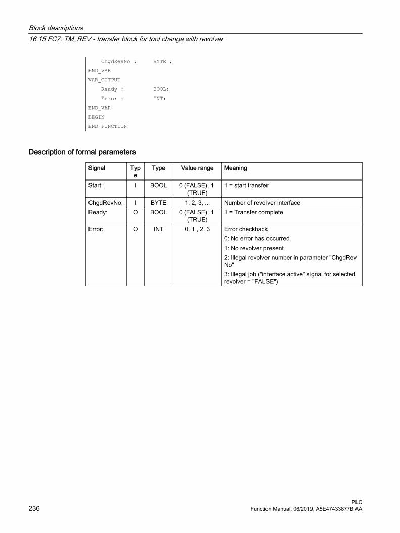
ChgdRevNo : BYTE ;END_VAR VAR_OUTPUT Ready : BOOL; Error : INT;END_VAR BEGIN END_FUNCTION
Description of formal parameters
Signal Type
Type Value range Meaning
Start: I BOOL 0 (FALSE), 1 (TRUE)
1 = start transfer
ChgdRevNo: I BYTE 1, 2, 3, ... Number of revolver interfaceReady: O BOOL 0 (FALSE), 1
(TRUE)1 = Transfer complete
Error: O INT 0, 1 , 2, 3 Error checkback0: No error has occurred1: No revolver present2: Illegal revolver number in parameter "ChgdRev‐No"3: Illegal job ("interface active" signal for selected revolver = "FALSE")
Block descriptions16.15 FC7: TM_REV - transfer block for tool change with revolver
PLC236 Function Manual, 06/2019, A5E47433877B AA

Pulse diagram
① User: Set request, Start = 0 → 1② FB4: PI service successfully completed, Ready = 1
User: Reset request, IF Ready == 1 THEN Start = 0③ User: IF Ready == 1 THEN reset request: 1 → 0④ FB4: Reset job confirmation, Ready = 0⑤ User: IF Ready == 0 AND Error == 0 THEN reset request Start = 1 → 0 not permissible⑥ FB4: PI service completed with errors, Error = 1
User: Reset request, IF Ready == 1 OR Error == 1 THEN Start = 0, possible further error handling
Call example
CALL FC7(
// Tool management: Transfer block for revolver
Start := m 20.5, // Start := "1 " => initiate the transfer
ChgdRevNo := DB61.DBB1, Ready := m 20.6, Error := DB61.DBW12 }; u m 20.6; // Poll readyr m 20.5; // Reset startspb m001; // Jump, if everything OKl db61.dbw 12; // Error informationow w#16#0; // Evaluate errorspn error; // Jump to troubleshooting, if <> 0m001: // Start of another programerror : r m 20.5; // Start reset, if an error has
occurred
Block descriptions16.15 FC7: TM_REV - transfer block for tool change with revolver
PLCFunction Manual, 06/2019, A5E47433877B AA 237

16.16 FC8: TM_TRANS - transfer block for tool management
Function The user calls this block FC TM-TRANS when the position of the tool or the status of the transfer operation changes. The parameter "TaskIdent" specifies the transfer job for the block FC8 at the tool management interface:
● For loading/unloading positions
● For spindle change positions
● For revolver change positions as transfer identifier
● Asynchronous transfer
● Asynchronous transfer with location reservation
The interface number is indicated in parameter "TaskIdentNo".
Example for loading point 5:
Parameter "TaskIdent":= 1 and "TaskIdentNo":= 5.
Furthermore, the current tool positions and status data (list of "Status" parameter in the following text) are also transferred for this transfer function.
Note
FC8 informs the NC of the current positions of the old tool.
The NC knows where the old and the new tool were located until the position change.
In the case of a transfer without a socalled "old tool" (e.g. on loading), the value 0 is assigned to parameters "OldToolMag", "OldToolLoc".
Block FC TM_TRANS may be started only with "Start" parameter = "TRUE" if an activation signal for the appropriate interface (DB71, DB72, DB73 in word 0) for this transfer has been supplied by the tool management function.
When this job is executed correctly, the output parameter "Ready" contains the value TRUE.
The user must then set the "Start" parameter to FALSE or not call the block again.
If the "Ready" parameter = FALSE, the error code in the "Error" parameter must be interpreted (see Call example FC8 and pulse diagram).
If the error code = 0, then this job must be repeated in the next PLC cycle (e.g. "Start" remains set to "TRUE"). This means that the transfer operation has not yet been completed.
If the user assigns a value of less than 100 to the "Status" parameter, then the associated interface in data block DB71 or DB72 or DB73, word 0 is deactivated (process completed). The appropriate bit for the interface is set to 0 by FC8.
The "Start" parameter does not need a signal edge for a subsequent job. This means that new parameters can be assigned with "Start = TRUE" immediately when "Ready = TRUE" is received.
Block descriptions16.16 FC8: TM_TRANS - transfer block for tool management
PLC238 Function Manual, 06/2019, A5E47433877B AA

Asynchronous transferTo ensure that changes in the position of a tool are automatically signaled from the PLC to the tool management (e.g. power failure during an active command or independent changes in the position by the PLC), FC8 is called with "TaskIdent" = 4 or 5. This call does not require interface activation by the tool management.
If parameter "TaskIdent" = 5, the tool management reserves the location in addition to changing the position. The location is only reserved if the tool has been transported from a real magazine to a buffer storage.
A relevant NC channel must be parameterized in the "TaskIdentNo" parameter.
The previous location of the tool is specified in the parameters "OldToolMag" and "OldToolLoc". The current location of the tool is specified in the parameters "NewToolMag", "NewToolLoc". "Status" = 1 must be specified.
With "Status" = 5, the specified tool remains at location "OldToolMag", "OldToolLoc". This location must be a buffer (e.g. spindle). The real magazine and location must be specified in the parameters "NewToolMag", "NewToolLoc"; the location is at the position of the buffer. This procedure must always be used if the tool management is to be informed of the position of a specific magazine location. This procedure is used for alignment in search strategies.
Boundary conditions● A cancellation of a transfer, e.g. by a channel reset, is not permitted.
● Parameter "Start" = 1, until parameter "Ready" == 1 or "Error" == 1
Further information● For detailed information about tool management, refer to
the Function Manual Tool Management.
● PI services for tool management
– FB4: PI_SERV - request PI service (Page 173)
– FC7: TM_REV - transfer block for tool change with revolver (Page 234)
– FC22: TM_DIR - direction selection for tool management (Page 283)
Declaration of the function
FUNCTION FC8: VOID//NAME :TM_TRANSVAR_INPUT Start : BOOL; TaskIdent: BYTE ; TaskIdentNo: BYTE ; NewToolMag: INT; NewToolLoc: INT; OldToolMag: INT; OldToolLoc: INT; Status: INT;END_VAR
Block descriptions16.16 FC8: TM_TRANS - transfer block for tool management
PLCFunction Manual, 06/2019, A5E47433877B AA 239

VAR_OUTPUT Ready : BOOL; Error : INT;END_VARBEGINEND_FUNCTION
Description of formal parameters
Signal Type Type Value range MeaningStart: I BOOL 0 (FALSE), 1
(TRUE)1: Start transfer
TaskIdent: I BYTE 1, 2, 3, 4, 5 Interface or task identifier1: Loading/unloading location2: Spindle change position3: Revolver change position4: Asynchronous transfer5: Asynchronous transfer with location reserva‐tion
TaskIdentNo: I BYTE 1, 2, 3 ... 10 Number of the associated interface or channel number.
NewToolMag: I INT -1, 0, 1, 2 ... Current magazine number of tool to be replaced-1: Tool remains at its location.NewToolLoc = any valueOnly permissible if TaskIdent = 2.
NewToolLoc: I INT 0, 1, 2 … max. location no.
Current location number of new tool
OldToolMag: I INT -1, 0 ... Current magazine number of tool to be replaced-1: The tool remains at its location. "OldToolLoc" = <any value>. Only permissible if "TaskIdent" = 2.
OldToolLoc: I INT Max. location number
Current location number of tool to be replaced
Status: I INT 1, 2, 3 ... 7, 103, 104, 105
Status information about transfer operation
Ready: O BOOL 0 (FALSE), 1 (TRUE)
1: Transfer completed
Error: O INT 0 ... 65535 Error checkback0: No error has occurred1: Unknown "TaskIdent"2: Unknown "TaskIdentNo"3: Impermissible job, ("Interface active" signal for selected revolver == 0)Other value: The number corresponds to the er‐ror message of the tool management function in the NC caused by this transfer.
Block descriptions16.16 FC8: TM_TRANS - transfer block for tool management
PLC240 Function Manual, 06/2019, A5E47433877B AA
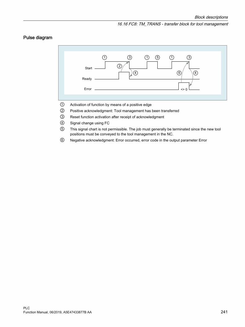
Pulse diagram
① Activation of function by means of a positive edge② Positive acknowledgment: Tool management has been transferred③ Reset function activation after receipt of acknowledgment④ Signal change using FC⑤ This signal chart is not permissible. The job must generally be terminated since the new tool
positions must be conveyed to the tool management in the NC.⑥ Negative acknowledgment: Error occurred, error code in the output parameter Error
Block descriptions16.16 FC8: TM_TRANS - transfer block for tool management
PLCFunction Manual, 06/2019, A5E47433877B AA 241

Status
Status Description1 The tool management job has been completed
The parameters "NewToolMag", "NewToolLoc", "OldToolMag", "OldToolLoc" of the FC8 block should be parameterized to the actual positions of the tools involved. Except in the case of preparing the change, they are normally the specified target positions of the tools of the asso‐ciated tool management interface, see also "Explanations of the formal parameters".1. In the case of loading/unloading/reloading, the tool has arrived at the required target
address. If the bit in the interface in DB 71.DBX (n+0).3 "position at loading point" is enabled, status 1 cannot be used for the function termination. Status 5 must be used for correct termination.
2. In the case of "Prepare change", the new tool is now available. The tool may, for example, be positioned in a buffer (gripper). In some cases, the target (magazine, location) of the old tool has been moved to the toolchange position after placement of the new tool in a buffer. However, the old tool still remains in the spindle. The preparations for a tool change are thus complete. After this acknowledgment, the "Change" command can be received. The positions in parameters "NewToolMag", "NewToolLoc", "OldToolMag" and "OldToolLoc" correspond to the current tool positions.
3. In the case of "Change" (spindle or revolver), the tools addressed in the interface have now reached the required target addresses. The tool change operation is thus completed.
2 The "new" tool cannot be made availableThis status is only admissible in conjunction with the "Change tool" command. When this status is applied, the PLC must be prevented from making a change with the proposed tool. The proposed (new) tool is disabled by the tool management function in the NC. A new command is then output by the tool management with a duplo tool. The positions in parameters "New‐ToolMag", "NewToolLoc", "OldToolMag", and "OldToolLoc" correspond to the original tool po‐sitions.
3 An error has occurredThe tool positions must not have been changed. Any changes to the magazine positions of the tool that have taken place in the meantime must be notified beforehand, for example, with status = 105 via FC8 transfer block. Only then will the tool positions be taken into account by the tool management function.
4 It would be better to position the "old" tool in the magazine position specified in parameters "OldToolMag" and "OldToolLoc"This status is permissible only in conjunction with preparation for tool change (change into spindle). The magazine location specified for the "old" tool must be free. Once this status has been passed to the tool management in the NC, a new preparation command is generated (Status_4 = final acknowledgment) and output to the DB72, for which the requested magazine position of the old tool is considered.No new tool search is performed explicitly, the positions for "NewToolMag" and "NewToolLoc" are taken from the original preparation command. But this is done only when this position is free. Parameters "NewToolMag" and "NewToolLoc" are not taken into account.
Block descriptions16.16 FC8: TM_TRANS - transfer block for tool management
PLC242 Function Manual, 06/2019, A5E47433877B AA

Status Description5 The operation is complete
The "new" tool is in the position specified in parameters "NewToolMag", "NewToolLoc". In this case, the specified tool is not really in this position, but is still in the same magazine location. However, this magazine location has been moved to the position set in the parameters (e.g. tool change position). This status may be used only for revolvers, chain-type magazines and disk magazines. The status enables the tool management function to adjust the current position of a magazine and to improve the search strategy for subsequent commands. This status is permissible only in conjunction with loading, unloading, and reloading operations and with preparations for a tool change. The "OldToolMag" and "OldToolLoc" parameters must be par‐ameterized with the data of a buffer.● Loading, reloading:
On loading or reloading, a location for the tool is already reserved in the NC. The machine operator must then insert the tool at the target location. Notice: The location reservation is canceled when the control system is switched on again.
● Tool-change preparation:Tool motions still to be executed are not carried out until after the tool has been changed.
● Positioning to the loading point:If the bit in the interface in DB 71.DBX (n+0).3 "position at loading point" is enabled, then only status 5 be used for the function termination (not status 1).
6 The tool management job has been completedThis status has the same function as status 1, but, in addition, a reservation of the source location is carried out. This status is only permitted when reloading. The command is ended and the source location of the tool is reserved if the target location is in a buffer magazine.
7 Initiate repetition of the command "Prepare Tool"This status is only admissible in conjunction with the "Change tool" command. This status is intended for use when the "new" tool has changed its position (e.g. via an asynchronous com‐mand of the "new" tool). After "Ready = 1" has been provided by FC8, the "Prepare Change" command is repeated automatically with the same tool. For the automatic repetition, a new tool search is carried out. The positions in parameters "NewToolMag", "NewToolLoc", "OldTool‐Mag", and "OldToolLoc" correspond to the original tool positions.
103 The "new" tool can be insertedThis status is permitted only in the tool change preparation, when the PLC may reject the new tool (e.g. in case of MD20310 $MC_TOOL_MANAGEMENT_MASK, bit 4=1 for the possibility, request changed parameter from PLC once again). The tool positions have remained un‐changed. This status is therefore necessary, when the processing is to be continued in the NC without an unnecessary stop.
104 The "new" tool is in the position specified in parameters "NewToolMag", "NewToolLoc"This status is only permissible if the tool is still in the magazine in the same location. The "old" tool is in the position (buffer) specified in parameters "OldToolMag", "OldToolLoc". In this case, however, the new tool is not really in this position, but is still in the same magazine location. However, this magazine location has been moved to the position set in the parameters (e.g. tool change position). This status may be used only in conjunction with revolvers, chaintype mag‐azines and disk magazines for the "Tool change preparation" phase. The status enables the tool management to adjust the current position of a magazine and to improve the search strat‐egy for subsequent commands.
105 The specified buffer location has been reached by all tools involvedStandard case if the operation has not yet been completed.The tools are in the specified tool positions (parameters "NewToolMag", "NewToolLoc", "Old‐ToolMag", "OldToolLoc").
Block descriptions16.16 FC8: TM_TRANS - transfer block for tool management
PLCFunction Manual, 06/2019, A5E47433877B AA 243

Status definitionA general rule for the acknowledgment status is that the status information 1 to 7 leads to the termination of the command. If FC8 receives a status information, the "Interface active bit" of the interface specified in FC8 is reset to "0" (see also interface lists DB 71 to DB 73). thus completing the operation. The behavior is different in the case of status information 103 to 105. When the FC8 receives a status information, the "Interface active bit" of this interface remains at "1". Further processing is required by the user program in the PLC (e.g. continuation of magazine positioning). This status information is generally used to transfer changes in position of one or both tools while the operation is still in progress.
Call example
CALL FC8( //Tool management transfer block Start := m 20.5, // Start := "1 " => initiate the transfer TaskIdent := DB61.DBB0, TaskIdentNo := DB61.DBB1, NewToolMag := DB61.DBW2, // Current position of new tool NewToolLoc := DB61.DBW4, OldToolMag := DB61.DBW6, // Current position of old tool OldToolLoc := DB61.DBW8, Status := DB61.DBW10, // Status Ready := m 20.6, Error := DB61.DBW12); u m 20.6; // Poll readyr m 20.5; // Reset startspb m001; // Jump if everything OKl DB61.dbw12; // Error informationow w#16#0; // Evaluate errorJC error; // Jump to troubleshooting m001: // Normal branch error : //Troubleshootingr m 20.5: // Reset start
16.17 FC9: ASUP - start of asynchronous subprograms
Function The block FC9 "ASUP" can be used to trigger any functions in the NC. Before an ASUP can be started from the PLC, it must have been selected and parameterized by an NC program or by FB4 (PI service ASUP). In this case, the channel and the interrupt numbers must match the parameters in FC9.
Block descriptions16.17 FC9: ASUP - start of asynchronous subprograms
PLC244 Function Manual, 06/2019, A5E47433877B AA
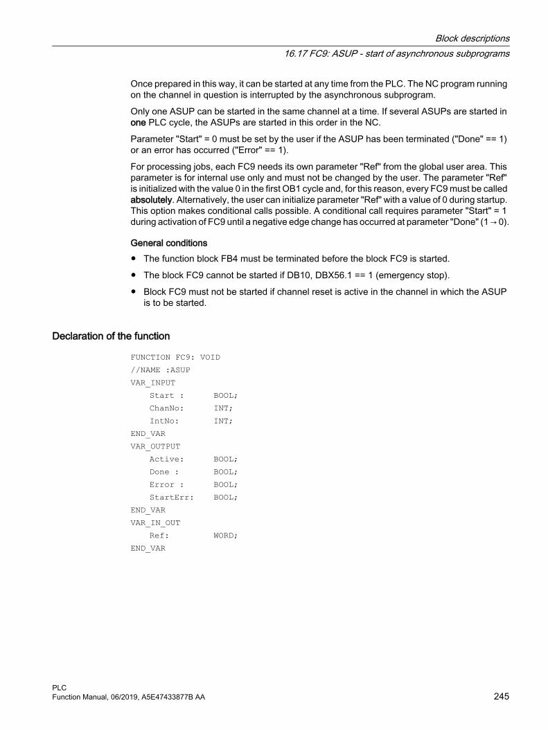
Once prepared in this way, it can be started at any time from the PLC. The NC program running on the channel in question is interrupted by the asynchronous subprogram.
Only one ASUP can be started in the same channel at a time. If several ASUPs are started in one PLC cycle, the ASUPs are started in this order in the NC.
Parameter "Start" = 0 must be set by the user if the ASUP has been terminated ("Done" == 1) or an error has occurred ("Error" == 1).
For processing jobs, each FC9 needs its own parameter "Ref" from the global user area. This parameter is for internal use only and must not be changed by the user. The parameter "Ref" is initialized with the value 0 in the first OB1 cycle and, for this reason, every FC9 must be called absolutely. Alternatively, the user can initialize parameter "Ref" with a value of 0 during startup. This option makes conditional calls possible. A conditional call requires parameter "Start" = 1 during activation of FC9 until a negative edge change has occurred at parameter "Done" (1 → 0).
General conditions● The function block FB4 must be terminated before the block FC9 is started.
● The block FC9 cannot be started if DB10, DBX56.1 == 1 (emergency stop).
● Block FC9 must not be started if channel reset is active in the channel in which the ASUP is to be started.
Declaration of the function
FUNCTION FC9: VOID//NAME :ASUPVAR_INPUT Start : BOOL; ChanNo: INT; IntNo: INT;END_VARVAR_OUTPUT Active: BOOL; Done : BOOL; Error : BOOL; StartErr: BOOL;END_VARVAR_IN_OUT Ref: WORD;END_VAR
Block descriptions16.17 FC9: ASUP - start of asynchronous subprograms
PLCFunction Manual, 06/2019, A5E47433877B AA 245

Description of formal parametersThe table below lists all formal parameters of the ASUP function.
Signal Type
Type Value range Description
Start: I BOOL 0 (FALSE), 1 (TRUE)
Job start with positive signal edge
ChanNo: I INT 1, 2, 3 ... 10 Channel numberIntNo: I INT 1, 2, 3 ... 8 Interrupt numberActive: O BOOL 0 (FALSE), 1
(TRUE)1: active
Done: O BOOL 0 (FALSE), 1 (TRUE)
1: ASUP completed
Error: O BOOL 0 (FALSE), 1 (TRUE)
1: Interrupt switched off
StartErr: O BOOL 0 (FALSE), 1 (TRUE)
1: Interrupt number not assigned or de‐leted
Ref: I/O WORD Global variable (MW, DBW,..)
1 word per FC9 (for internal use)
Pulse diagram
(1) Activation of function(2) ASUP is active(3) Positive acknowledgment: ASUP completed(4) Reset function activation after receipt of acknowledgment(5) Signal change using FC(6) Not permitted If function activation is reset prior to receipt of acknowledgement, the output signals
are not updated without the operational sequence of the activated function being affected.(7) Negative acknowledgement: An error occurred
Block descriptions16.17 FC9: ASUP - start of asynchronous subprograms
PLC246 Function Manual, 06/2019, A5E47433877B AA

Call example
CALL FC9( //Start an asynchronous subprogram//in channel 1 interrupt number 1
Start := I 45.7, ChanNo := 1, IntNo := 1, Active := M 204.0, Done := M204.1, Error := M 204.4, StartErr := M 204.5, Ref := MW 200);
16.18 FC10: AL_MSG - error and operating messages
Function With block FC10 "AL_MSG", the signals entered in DB2 are evaluated and displayed as incoming or outgoing error messages and operational messages on the user interface.
The incoming signals (positive edge) are displayed immediately in the case of both error and operational messages.
Outgoing signals (negative edge) are deleted immediately only for operational messages. In the event of error messages, the messages that are no longer pending are only deleted with the parameter "Quit", i.e. errors remain displayed on the user interface until they have been acknowledged by the user even if the signals are no longer pending.
The "ToUserIF" parameter can be used to transfer the group signals for the feed, read and NC start disabling signals and feed stop signal to the existing axis, spindle and channel interfaces. The group signals are transferred to the user interface directly from the status information in DB2 irrespective of an alarm acknowledgment.
1. If parameter "ToUserIF" = 0, there is no transfer of the signals to the user interface. In this case, the user must take measures in his PLC program to ensure that these signals are influenced in the interface. The FB1 parameter "ExtendChanAxMsg" is evaluated and so avoids the limitation of the usable message ranges by configuring the NCK machine data.
2. If parameter "ToUserIF" = 1, all signals listed above are sent to the user interface as a group signal in each case. The user PLC program can, therefore, influence these signals only via DB2 in conjunction with a message or alarm output. The appropriate information is overwritten in the user interface.
Alternatively to the response described in paragraph 2, the disable and hold signals can be influenced without a message being output by influencing the interface signals with a disable or stop signal state after FC10 is called.
The following program illustrates this method:
CALL FC10( ToUserIF := TRUE,
Block descriptions16.18 FC10: AL_MSG - error and operating messages
PLCFunction Manual, 06/2019, A5E47433877B AA 247

Ackn := I 6.1); u m 50.0; // Feed disable for channel 1to DB 21; s dbx 6.0; // Setting the blocking condition
// Resetting is done via FC AL_MSG// if M 50.0 outputs the signal "0".
FB1 parameter "ExtendAlMsg"With FB1 parameter "ExtendAlMsg" = TRUE, the new DB2 structure becomes effective (see "Interface PLC/HMI (Page 62)"). For the activation, bit fields for the lock and stop signals are available for 10 channels, 31 axes and maximum 64 user areas (the number of user areas is entered in the FB1 parameter "MsgUser"). The associated functionality is obtained automatically by simply setting/resetting signals in DB2.
The error and operational messages in data block DB2 must be provided in a user-specific way.
FB1 parameter "ExtendChanAxMsg"With the activation of this parameter, a channel- or axis-number independent acquisition of alarms and messages acts. All DB2 areas are available for users. Group signals cannot be transferred to the user interface. The parameter is evaluated only when the FC10 parameter "ToUserIF" is deactivated.
Display on HMIIn DB2, a "1" signal must be present for several OB1 cycles to ensure that a message can also be displayed on the HMI.
There is an upper limit for the number of alarms and messages that can be pending at the same time. This upper limit is dependent on the PLC CPU. On PLC 317-2DP, the upper limit for messages pending simultaneously is 60.
Further information:PLC alarms/messages (Page 317)
Declaration of the function
FUNCTION FC10: VOID // NAME: AL_MSGVAR_INPUT ToUserIF : BOOL; Ackn : BOOL;END_VAR END_FUNCTION
Block descriptions16.18 FC10: AL_MSG - error and operating messages
PLC248 Function Manual, 06/2019, A5E47433877B AA

Description of formal parameters
Signal Type Type Value range MeaningToUserIF : I BOOL 0 (FALSE), 1
(TRUE)1: Transfer of the signals to the user inter‐face in each cycle
Ackn: I BOOL 0 (FALSE), 1 (TRUE)
1: Acknowledgment of error messages
Call example
CALL FC10( // Error and operational messages ToUserIF := TRUE, // Signals from DB2 are transferred to interface. Ackn := E6.1 // Acknowledgment of error message via input I6.1);
16.19 FC12: AUXFU - call interface for user with auxiliary functions
FunctionThe block FC12 "AUXFU" is called on an eventdriven basis in the basic program if the channel transferred in the input parameter contains new auxiliary functions. The PLC user can extend FC AUXFU with program instructions for processing his auxiliary function to avoid cyclic polling of the channel DBs. This mechanism permits auxiliary functions to be processed on a jobdriven basis. FC AUXFU is supplied as a compiled empty block in the basic program. In this case, the basic program supplies parameter "Chan" with the channel number. The PLC user knows which channel has new auxiliary functions available. The new auxiliary functions can be determined by the auxiliary-function change signals in the channel concerned.
Declaration of the function
FUNCTION FC12: VOID // Event control of auxiliary functionsVAR_INPUT Chan: BYTE ;END_VARBEGIN BE;END_FUNCTION
Explanation of formal parameters
Signal Type Type Value range DescriptionChan: I BYTE 0, 1, 2 ... 9 Index of the channel = channel number -1
Block descriptions16.19 FC12: AUXFU - call interface for user with auxiliary functions
PLCFunction Manual, 06/2019, A5E47433877B AA 249

Example
FUNCTION FC12: VOID // Event control of auxiliary functionsVAR_INPUT Chan: BYTE ; // Parameter is supplied by basic programEND_VARVAR_TEMP ChanDB: INT;END_VAR BEGINL Chan; // Channel index+ 21; // Channel DB offsetT ChanDB; // Save channel DB no.TO DB[ChanDB]; // Channel DB is opened indirectly// Auxiliary-function change signals are now scanned, etc. BE;END_FUNCTION
16.20 FC13: BHGDisp - display control for handheld unit
Function Block FC13 "BHGDisp" handles the display control for the handheld unit (HHU or HT 2). The information that is to appear on the display must be saved to a string variable. The pointer to the string is specified in the parameter "ChrArray". To do this, a fixed text assignment of 32 characters (HHU) or 64 characters (HT 2) is needed when the data block for this string is created.
16 characters are sent to the HHU per job. The assignment of the characters in the "ChrArray" for the respective line is unambiguous. For line 1, characters 1 to 16 and for line 2, characters 17 to 32 of the string data ChrArray are transferred. In addition, for HT 2 line 3 with characters 33 to 48 is displayed and line 4 with characters 49 to 64. A job takes several OB1 cycles.
DisplayBlock FC13 checks whether the necessary minimum length of the "ChrArray" exists for operating the handheld unit. If fewer characters exist in the string variables than should be displayed, the line is filled with blank spaces. If several variables are to be entered in the string in one or more PLC cycles without a display output, the display output can be suppressed by parameter "Row" = 0. The transfer of the characters to the rows takes several OB1 cycles. If several rows are to be updated "simultaneously" (parameter "Row" > 1), the rows are updated successively with 16 characters per row.
Variable portions Variable components within the string can be inserted using the optional number converter functionality with the parameter "Convert" = 1. The variable to be displayed is referenced via the parameter "Addr". The format of the variables is described in the parameter "DataType". The
Block descriptions16.20 FC13: BHGDisp - display control for handheld unit
PLC250 Function Manual, 06/2019, A5E47433877B AA

number of bytes of the variable is linked to the format description. The address justified to the right within the string is specified by parameter "StringAddr". The number of written characters is shown in the parameter table.
High display resolutionIf, for example, the axis value is to be displayed with a higher resolution, the following must be observed:
● The variables are read as before with FB2 or FB5. Instead of anypointer BYTE 8 as criterion for output as 64-bit floating point number, REAL 2 is used (e.g.: P#M100.0 REAL 2).
● When specifying the 64-bit floating point number on the HHU/HT 2, you can select the output format with up to 14 places, distributed freely before and after the decimal point, instead of fixed, specified formats.
HHU output signalsByte 1 is used by the HHU output signals and the character specifications are used by the block FC13. These may not be written by the PLC user program.
Relevant FB1 parameters
Handheld unit HHUIn OB100, the FB1 parameters must be set for the input and output data of the handheld unit:
● Parameter "BHGIn" corresponds to the input data of the PLC from the handheld unit (data received by PLC)
● Parameter "BHGOut" corresponds to the output data of the PLC to the handheld unit (data transmitted by PLC).
The two pointers must be set to the starting point of the relevant data area, which is also parameterized in SDB 210 with an MPI link.
The FB1 parameter "HHU" = 2 must be set for operating an HHU.
HT 2 handheld terminalIf HT 2 is used, FB1 parameter "HHU" = 5 must be set. The parameters of the input and output data must be set, as described in the above paragraph "Handheld Unit HHU".
The value that was configured at S2 of the DIP-Fix switch (rotary coding switch) of the connecting module of the HT 2 must be assigned to the parameters "BHGRecGDNo" and "BHGRecGBZNo".
Declaration of the function
DATA_BLOCK "strdat" STRUCT disp: STRING [32]:= 'character_line1 character_line2'; END_STRUCT;BEGINEND_DATA_BLOCK
Block descriptions16.20 FC13: BHGDisp - display control for handheld unit
PLCFunction Manual, 06/2019, A5E47433877B AA 251

FUNCTION FC13: VOID VAR INPUT Row : BYTE ; ChrArray : STRING ; Convert : BOOL; Addr: POINTER; DataType : BYTE ; StringAddr
:INT;
Digits : BYTE ; END VAR VAR OUTPUT Error : BOOL; END VAR
Description of formal parameters
Signal Type Type Value range DescriptionRow : I BYTE 0, 1, 2, ... 8
B#16#FDisplay line "binary" evaluation0: no display output1: Line 12: Line 23: Line 1 and line 2 to be changed4: Line 35: Line 1 and line 3 to be changed8: Line 4B#16#F automatic change of all 4 lines
ChrArray : I STRING "DBName".<VarName> Display content as pointer to stringstring[32]: not HT 2string[64]: HT 2
Convert : I BOOL 0 (FALSE), 1 (TRUE) Activation of numerical conversionAddr: I Pointer Pointer to the variable to be converted
Block descriptions16.20 FC13: BHGDisp - display control for handheld unit
PLC252 Function Manual, 06/2019, A5E47433877B AA

Signal Type Type Value range DescriptionDataType: I BYTE 1, 2, 3 ... 8,
B#16#13,B#16#30
Data type of the tag1: BOOL, 1 character2: BYTE, 3 characters3: CHAR, 1 character4: WORD, 5 characters5: INT, 6 characters6: DWORD, 7 characters7: DINT, 8 characters8: REAL, 9 characters(7 digits plus a sign and a decimal point; for places after the decimal point, refer to the Digits Parameter)B#16#13: String, up to 32/64 charac‐ters, "Addr" must be a pointer to a STRING.B#16#30: REAL64,(12 characters: 10 digits plus a sign and a decimal point; for places after the dec‐imal point, refer to the Digits Parameter)
StringAddr : I INT 1 ... 32 / 64 Right-justified address within variable from "ChrArray"
Digits : I BYTE 1, 2, 3 ... 9 Number of places after the decimal point:1 ... 4: DataType REAL1 ... 9: DataType REAL64
Error: O BOOL 0 (FALSE), 1 (TRUE) Error1: An error occurred
Ranges of values
Ranges of values of data typesData type Representable numerical range
BOOL 0, 1BYTE 0 ... 255WORD 0 ... 65535
INT - 32768 ... 32767DWORD 0 ... 9999999
DINT -9999999 ... 9999999REAL (Digits := 1) -999999.9 ... 999999.9REAL (Digits := 2) -99999.99 ... 99999.99REAL (Digits := 3) -9999.999 ... 9999.999
... ...REAL (Digits := 9) -0.9999999 ... 0.9999999
Block descriptions16.20 FC13: BHGDisp - display control for handheld unit
PLCFunction Manual, 06/2019, A5E47433877B AA 253

Call example// DB with name strdat in the simple table, data element disp is declared as String[32] (for HT 2: // String[64]) and completely assigned with characters
CALL FC13( Row := MB 26, ChrArray := "strdat".disp
,
Convert := M 90.1, Addr := P#M 20.0, // Number to be converted DataType := MB 28, // Data type of the variables StringAddr := MW 30, Digits := B#16#3, // 3 decimal places Error := M 90.2);
16.21 FC17: YDelta - star-delta switchover
FunctionBlock FC17 is used for star-delta changeover for digital main spindle drives. The changeover can be made in both directions (star > delta or delta > star).
PrerequisiteThe prerequisite is two isolated contactors. The contactors are controlled via the peripheral output signals configured at the FC17 outputs: "Y" or "Delta".
Internal sequence The internal sequence when changing over between star and delta after switching over the FC17 control signal is described in the following: "YDelta" displayed.
1. DB31, ... .DBX21.5 = 0 (reset feedback signal "motor selected")DB31, ... .DBX21.x = 1 (set request "2nd motor data set" corresponding to the interface parameterization DB31, ... .DBX130.0 - 4)
2. DB31, ... .DBX93.7 == 0 (feedback signal "pulses enabled" was reset) ⇒
– Start FC17 timer
– FC17: "Y" = 0 (reset output for star contactor)
3. After the FC17 timer elapses (FC17: "TimeVal") ⇒
– FC17: "Y" = 1 (set output for delta contactor)
4. After the FC17 timer elapses again (FC17: "TimeVal") ⇒
– The pulses are again internally set
– DB31, ... .DBX93.7 == 1 (feedback signal "pulses enabled" was set)
– DB31, ... .DBX21.5 = 0 (feedback signal "motor selected" was set)
Block descriptions16.21 FC17: YDelta - star-delta switchover
PLC254 Function Manual, 06/2019, A5E47433877B AA

Signal flow
① FC17 input: Signal for star-delta changeover② - Changeover: Star > delta ③ - Changeover: Delta > star④ FC17 input: Parameterizable changeover time ""TimeVal" ⑤ - Wait time until the control of the output signal: "Y" or "delta"⑥ - Wait time until pulse enable⑦ FC17 output: Signals for contactor control
Further information
For additional explanations of motor speed adjustments, see:
● Function Manual Axes and Spindles; spindles; configurable gear adaptations
● Function Manual Axes and Spindles; speeds, setpoint/target value syst., closed-loop control
NoteDrive parameters
The following drive parameters must be considered for a star-delta changeover:● p833 (dataset changeover configuration)
– Bit 0 = 1 (contactor switchover via application)– Bit 1 = 0 (pulse cancellation by drive)
● p826 (motor changeover motor number)● p827 (motor changeover status word bit number)
Block descriptions16.21 FC17: YDelta - star-delta switchover
PLCFunction Manual, 06/2019, A5E47433877B AA 255

Boundary conditions● Block FC17 must be called absolutely and separately for each spindle.
● The drive pulses are deactivated during a star-delta changeover. The feedback signal to the PLC is realized using:
– DB31, ... .DBX93.7 == 0 (pulses enabled)
– DB31, ... .DBX61.7 == 0 (current controller active)
– DB31, ... .DBX61.6 == 0 (speed controller active)
● For a spindle which is located in an axis mode such as M70 or SPOS, a start-delta changeover is not carried out.
● For a closed-loop position controlled spindle (DB31, ... .DBX61.5 == 1 (position control active) ), while the spindle is moving it is not permissible to carry out a star-delta changeover.In the case of a fault, Alarm 25050 "Contour monitoring" is displayed, and the star-delta changeover is not executed.
● Once the star-delta changeover has been initiated using FC17, it cannot be delayed by the user, e.g. by waiting until the star-delta contactors change over during the course of operation. A delay such as this must be implemented by the user in the PLC user program.
Declaration of the function
VAR_INPUT YDelta: BOOL; SpindleIFNo: INT; TimeVal: S5TIME ; TimerNo : INT; END_VARVAR_OUTPUT Y: BOOL; Delta: BOOL; END_VARVAR_IN_OUT Ref: WORD; END_VAR
Description of formal parameters
Signal Type Type Value range MeaningYDelta: I BOOL 0 (FALSE), 1
(TRUE)Input signal for star-delta changeoverThe changeover is initiated by a signal change:● 0 (FALSE): Star● 1 (TRUE): Delta
SpindleIFNo: I INT 1 ... Number of the spindle interface (number of the associated machine axis)
Block descriptions16.21 FC17: YDelta - star-delta switchover
PLC256 Function Manual, 06/2019, A5E47433877B AA
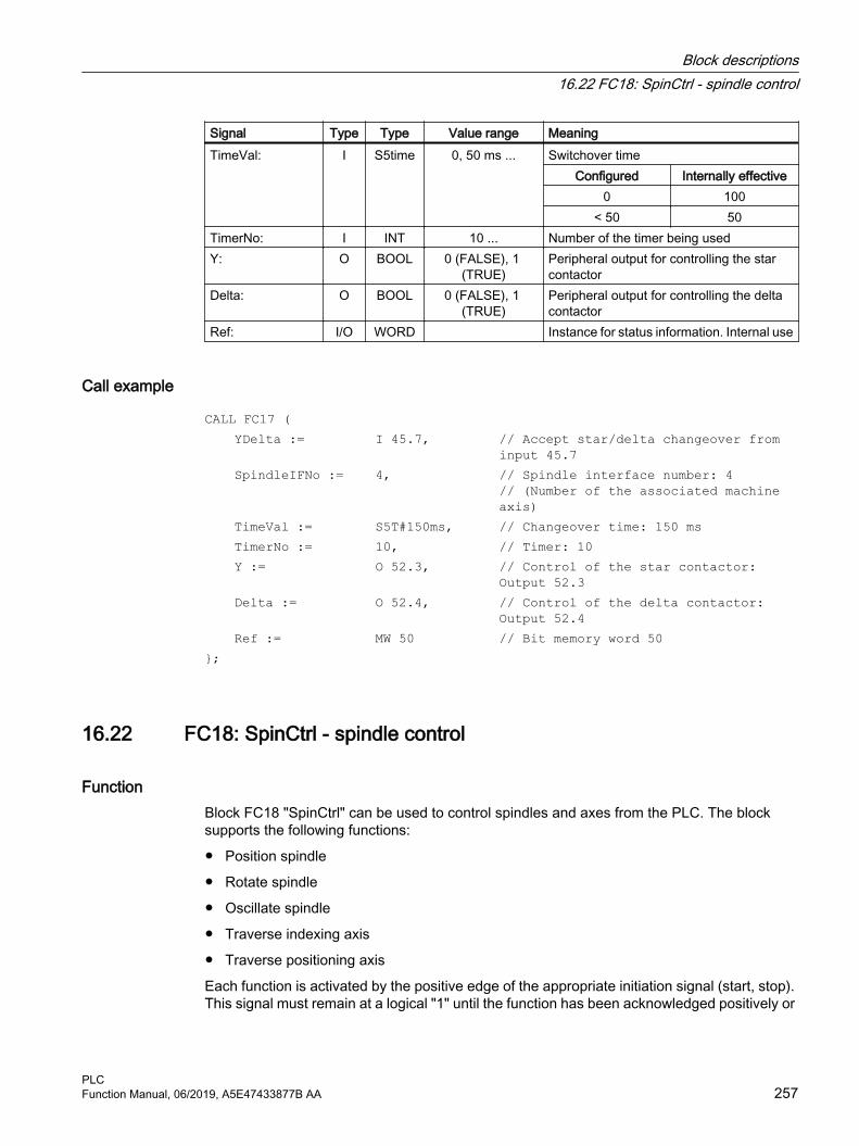
Signal Type Type Value range MeaningTimeVal: I S5time 0, 50 ms ... Switchover time
Configured Internally effective0 100
< 50 50TimerNo: I INT 10 ... Number of the timer being usedY: O BOOL 0 (FALSE), 1
(TRUE)Peripheral output for controlling the star contactor
Delta: O BOOL 0 (FALSE), 1 (TRUE)
Peripheral output for controlling the delta contactor
Ref: I/O WORD Instance for status information. Internal use
Call example
CALL FC17 ( YDelta := I 45.7, // Accept star/delta changeover from
input 45.7 SpindleIFNo := 4, // Spindle interface number: 4
// (Number of the associated machine axis)
TimeVal := S5T#150ms, // Changeover time: 150 ms TimerNo := 10, // Timer: 10 Y := O 52.3, // Control of the star contactor:
Output 52.3 Delta := O 52.4, // Control of the delta contactor:
Output 52.4 Ref := MW 50 // Bit memory word 50};
16.22 FC18: SpinCtrl - spindle control
FunctionBlock FC18 "SpinCtrl" can be used to control spindles and axes from the PLC. The block supports the following functions:
● Position spindle
● Rotate spindle
● Oscillate spindle
● Traverse indexing axis
● Traverse positioning axis
Each function is activated by the positive edge of the appropriate initiation signal (start, stop). This signal must remain at a logical "1" until the function has been acknowledged positively or
Block descriptions16.22 FC18: SpinCtrl - spindle control
PLCFunction Manual, 06/2019, A5E47433877B AA 257

negatively by InPos="1" or Error = "1". The output parameters are deleted when the relevant trigger signal is reset and the function has been completed.
To be able to control an axis or spindle via the PLC, it must be activated for the PLC. This can, for example, be achieved by calling the block with activation of the "Start" or "Stop" parameter. When you do this, the block requests control of the spindle/axis from the NC.
The NC signals the status of the spindle/axis in the associated axis-specific interface DB31, ... DBX68.4 - 7. Once the axis/spindle is operating under PLC control, the travel command for the active status can be evaluated via the relevant axis-specific interface.
Upon completion ("InPos" is True, "Start" changes to zero), the axis/spindle check function is switched to a neutral status using block FC18.
Alternatively, the PLC user program can also request control for the PLC before calling FC18.
By calling this function several times in succession, a better response by the spindle/axis can be obtained as the changeover process in the FC can be omitted.
Activation through the PLC user program is executed in the corresponding spindle interface in byte 8.
After return of the check, the spindle can again be programmed by the NC program.
Further information● Function Manual Axes and Spindles; spindles
● Function Manual Axes and Spindles; positioning axes
● Function Manual Axes and Spindles; indexing axes
WARNING
Changed response behavior of the axis/spindle
If several block calls (FC18) have been programmed for the same axis/spindle in the PLC user program, then the functions concerned must be interlocked by conditional calls in the user program. The conditional call of a started block (parameter Start or Stop = TRUE) must be called cyclically until the signal state of output parameter "Active" or "InPos" changes from 1 to 0.
Block descriptions16.22 FC18: SpinCtrl - spindle control
PLC258 Function Manual, 06/2019, A5E47433877B AA

NoteCall note
FC18 must be called cyclically until signal "InPos" or, in the case of an error "Error", produces an edge transition of 1 to 0. An additional "Start" or "Stop" is only possible for this spindle/axis when the "InPos"/"Error" signal has supplied a value of 0. (the system must wait for at least one PLC cycle with the next "Start" or "Stop"). This also applies when the assignment in data byte 8 on the axial interface has been changed.Abort
The function cannot be aborted by means of parameter "Start" or "Stop", but only by means of the axial interface signals (e.g. delete distance-to-go). The axial interface also returns status signals of the axis that may need to be evaluated (e.g. exact stop, traverse command).Simultaneity
Several axes can be traversed simultaneously or subject to a delay by FC18 blocks. The upper limit is only limited by the maximum number of axes of the NC.Axis disable
For a set axis inhibit (DB31, ... .DBX1.4 == 1), the axis controlled via FC18 does not move. Only a simulated actual value is generated. Same behavior as when traversing the axis for an axis inhibit by the NC.
Functions
Function 1: Position spindle
Parameter MeaningStart : 0 → 1: Start the functionFunct : 1: Function number for "Position spindle"Mode : Positioning modes 1, 2, 3, 4 (refer to the paragraph below, "Explanation of the
formal parameters"AxisNo : Number of machine axisPos : PositionFRate : FRate ≠ 0: Positioning velocity
FRate = 0: Velocity corresponding to MD35300 $MA_SPIND_POSCTRL_VE‐LO
InPos : 1: Position reached with "Exact stop fine"Error : 1: Positioning errorState : Error code
Function 2: Rotate spindle
Parameter MeaningStart : 0 → 1: Start the functionStop : 0 → 1: Stop the functionFunct : 2: Function number for "Rotate spindle"
Block descriptions16.22 FC18: SpinCtrl - spindle control
PLCFunction Manual, 06/2019, A5E47433877B AA 259

Parameter MeaningMode : Mode = 5: direction of rotation M4
Mode ≠ 5: direction of rotation M3AxisNo : Number of machine axisFRate : Spindle speedInPos : 1: Setpoint speed is output, also see DB31, ... DBX83.5 (spindle in the set‐
point range)Error : 1: Positioning errorState : Error code
Function 3: Oscillate spindle
Parameter MeaningStart : 0 → 1: Start the functionStop : 0 → 1: Stop the functionFunct : 3: Function number for "Oscillate spindle"AxisNo : Number of machine axisPos : Set gear stageInPos : 1: Setpoint speed is output, also see DB31, ... DBX83.5 (spindle in the set‐
point range)Error : 1: Positioning errorState : Error code
Parameterized oscillation speed: MD35400 $MA_SPIND_OSCILL_DES_VELO
The function of the parameter "Pos" depends on the setting in MD35010 $MA_GEAR_STEP_CHANGE_ENABLE = <value>
<Value> Pos Function0 0, 1, 2, ... 5 Oscillation1 0 Oscillation with gear stage change M40
1 Oscillation with gear stage change M412 Oscillation with gear stage change M423 Oscillation with gear stage change M434 Oscillation with gear stage change M445 Oscillation with gear stage change M45
Function 4: Traverse indexing axes
Note
The modulo conversion can be compared with approaching the indexing position via POS[AX] = CIC (value) in the part program.
Block descriptions16.22 FC18: SpinCtrl - spindle control
PLC260 Function Manual, 06/2019, A5E47433877B AA
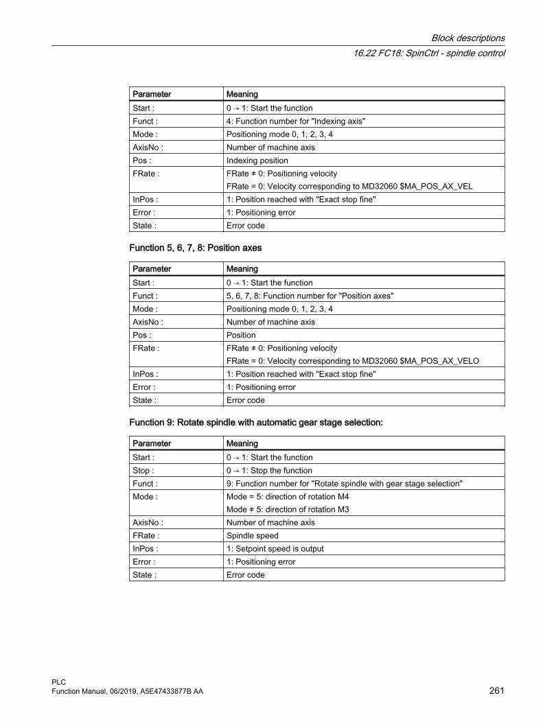
Parameter MeaningStart : 0 → 1: Start the functionFunct : 4: Function number for "Indexing axis"Mode : Positioning mode 0, 1, 2, 3, 4AxisNo : Number of machine axisPos : Indexing positionFRate : FRate ≠ 0: Positioning velocity
FRate = 0: Velocity corresponding to MD32060 $MA_POS_AX_VELInPos : 1: Position reached with "Exact stop fine"Error : 1: Positioning errorState : Error code
Function 5, 6, 7, 8: Position axes
Parameter MeaningStart : 0 → 1: Start the functionFunct : 5, 6, 7, 8: Function number for "Position axes"Mode : Positioning mode 0, 1, 2, 3, 4AxisNo : Number of machine axisPos : PositionFRate : FRate ≠ 0: Positioning velocity
FRate = 0: Velocity corresponding to MD32060 $MA_POS_AX_VELOInPos : 1: Position reached with "Exact stop fine"Error : 1: Positioning errorState : Error code
Function 9: Rotate spindle with automatic gear stage selection:
Parameter MeaningStart : 0 → 1: Start the functionStop : 0 → 1: Stop the functionFunct : 9: Function number for "Rotate spindle with gear stage selection"Mode : Mode = 5: direction of rotation M4
Mode ≠ 5: direction of rotation M3AxisNo : Number of machine axisFRate : Spindle speedInPos : 1: Setpoint speed is outputError : 1: Positioning errorState : Error code
Block descriptions16.22 FC18: SpinCtrl - spindle control
PLCFunction Manual, 06/2019, A5E47433877B AA 261

Function 10, 11: Rotate spindle with constant cutting rateThe "Constant cutting rate" function (G96) must be active in the NC.
Parameter MeaningStart : 0 → 1: Start the functionStop : 0 → 1: Stop the functionFunct : 10: Function number for "Constant cutting rate (m/min)"
11: Function number for "Constant cutting rate (feet/min)"Mode : Mode = 5: direction of rotation M4
Mode ≠ 5: direction of rotation M3AxisNo : Number of machine axisFRate : Cutting rateInPos : 1: Setpoint speed is outputError : 1: Positioning errorState : Error code
Declaration of the function
FUNCTION FC18: VOID //SpinCtrlVAR_INPUT Start : BOOL; Stop : BOOL; Funct : BYTE ; Mode : BYTE ; AxisNo : INT; Pos : REAL; FRate : REAL;END_VAR VAR_OUTPUT InPos : BOOL; Error : BOOL; State : BYTE ;END_VAR
Description of formal parameters
Signal Type
Type Value range Meaning
Start: I BOOL 0 (FALSE), 1 (TRUE)
0 → 1: Start the function
Stop: I BOOL 0 (FALSE), 1 (TRUE)
0 → 1: Stop the function
Block descriptions16.22 FC18: SpinCtrl - spindle control
PLC262 Function Manual, 06/2019, A5E47433877B AA

Signal Type
Type Value range Meaning
Funct: I BYTE 1, 2, 3, ... 11 1: Position spindle2: Rotate spindle3: Oscillate spindle4: Indexing axis5: Positioning axis metric6: Positioning axis inch7: PosAxis metric with handwheel override8: PosAxis inch with handwheel override9: Rotate spindle with automatic gear stage selec‐tion10: Rotate spindle with constant cutting rate (m/min)11: Rotate spindle with constant cutting rate (feet/min)
Mode: I BYTE 0, 1, 2, ... 5 0: Positioning to absolute position1: Positioning incremental2: Positioning along the shortest path3: Positioning absolute, positive approach direc‐tion4: Positioning absolute, negative approach direc‐tion5: Direction of rotation as for M4
AxisNo: I INT 1, 2, 3, ... 31 Number of the axis/spindle to be traversedPos: I REAL ∓ 0.1469368 I -38 to
∓ 0.1701412 I +39Rotary axis: Degrees Indexing axis: Indexing position Linear axis: mm or inches
FRate: I REAL ∓ 0.1469368 I -38 to ∓ 0.1701412 I +39
Rotary axis and spindle: [rev/min]Linear axes: [m/min] or [ft/min]
InPos: O BOOL 0 (FALSE), 1 (TRUE)
1: Position reached or function executed
Error: O BOOL 0 (FALSE), 1 (TRUE)
1: Error
State: O BYTE 0, 1, 2, ... 255 Error code
Error identifiersAn error is active, if: Parameter "Error" == 1 (TRUE)
The cause of the error is displayed in: Parameter "State"
State MeaningCause of the error on the PLC side
1 Several functions of the axis/spindle were activated simultaneously20 A function was started without the position being reached30 The axis/spindle was transferred to the NC while still in motion
Block descriptions16.22 FC18: SpinCtrl - spindle control
PLCFunction Manual, 06/2019, A5E47433877B AA 263

State Meaning40 The axis is programmed by the NC program, NC internal error50 Permanently assigned PLC axis: Traverses (JOG) or references60 Permanently assigned PLC axis: Channel status does not permit a start
Cause of the error on the NC side100 Incorrect position programmed for axis/spindle (corresponds to alarm 16830)101 Programmed speed is too high102 Incorrect value range for constant cutting rate (corresponds to alarm 14840)104 Following spindle: Illegal programming (corresponds to alarm 22030)105 No measuring system available (corresponds to alarm 16770)106 Axis positioning still active (corresponds to alarm 22052)107 Reference mark not found (corresponds to alarm 22051)108 No transition from speed control to position control (corresponds to alarm 22050)109 Reference mark not found (corresponds to alarm 22051)110 Velocity/speed is negative111 Setpoint speed == zero112 Invalid gear stage115 Programmed position has not been reached117 G96/G961 is not active in the NC118 G96/G961 is still active in the NC120 Axis is not an indexing axis (corresponds to alarm 20072)121 Indexing position error (corresponds to alarm 17510)125 DC (shortest distance) not possible (corresponds to alarm 16800)126 Absolute value minus not possible (corresponds to alarm 16820)127 Absolute value plus not possible (corresponds to alarm 16810)128 No transverse axis available for diameter programming (corresponds to alarm 16510)130 Software limit switch plus (corresponds to alarm 20070)131 Software limit switch minus (corresponds to alarm 20070)132 Working area limit plus (corresponds to alarm 20071)133 Working area limit minus (corresponds to alarm 20071)134 Frame not permitted for indexing axis135 Indexing axis with "Hirth joint" is active (corresponds to alarm 17501)136 Indexing axis with "Hirth joint" is active and axis not referenced (corresponds to alarm 17503)137 Spindle operation not possible for transformed spindle/axis (corresponds to alarm 22290)138 Axis: Coordinate system-specific working area plus violated (corresponds to alarm 20082)139 Axis: Coordinate system-specific working area minus violated (corresponds to alarm 20082)
System error200 corresponds to alarm 450007
Alarm numbers: Further information Diagnostics Manual
Block descriptions16.22 FC18: SpinCtrl - spindle control
PLC264 Function Manual, 06/2019, A5E47433877B AA

Signal sequence: Normal case
① PLC user program: Function start using a positive edge: 0 → 1② NC: Positive acknowledgment, function executed / position reached③ PLC user program: Reset after detecting the positive acknowledgment④ FC18: Reset of the positive acknowledgment
Signal sequence: Error case
① PLC user program: Function start using a positive edge: 0 → 1② NC: Negative acknowledgment, error occurred③ PLC user program: Reset after detecting the negative acknowledgment④ FC18: Reset of the negative acknowledgment
Call examples
Example 1: Position spindle:
//Positive acknowledgment resets Start:U M112.0; //InPos
Block descriptions16.22 FC18: SpinCtrl - spindle control
PLCFunction Manual, 06/2019, A5E47433877B AA 265

R M 100.0; //Start//Negative acknowledgment, after error evaluation (state: MB114) reset with T12 startU M113.0; // ErrorU E 6.4; //Key T12R M 100.0; //Start//Start with T13U E 6.3; //Key T13UN M 112.0; //Restart only when InPos or Error = 0UN M 113.0; S M 100.0; CALL FC18( Start := M100.0, Stop := FALSE, Funct := B#16#1, //Position spindle Mode := B#16#2, //Shortest path AxisNo := 5, Pos := MD104, FRate := MD108, InPos := M112.0, Error := M113.0, State := MB114);
Example 2: Start spindle rotation:
CALL FC18( Start := M100.0, Stop := FALSE, Funct := B#16#2, //Rotate spindle Mode := B#16#5, //Direction of rotation as for M4 AxisNo := 5, Pos := 0.0, FRate := MD108, InPos := M112.0, Error := M113.0, State := MB114);
Example 3: Start spindle oscillation
CALL FC18( Start := M100.0, Stop := FALSE, Funct := B#16#3, //Oscillate spindle Mode := B#16#0, AxisNo := 5, Pos := 0.0,
Block descriptions16.22 FC18: SpinCtrl - spindle control
PLC266 Function Manual, 06/2019, A5E47433877B AA

FRate := MD108, InPos := M112.0, Error := M113.0, State := MB114);
Example 4: Traverse indexing axis
CALL FC18( Start := M100.0, Stop := FALSE, //Not used Funct := B#16#4, //Traverse indexing axis Mode := B#16#0, //Absolute positioning AxisNo := 4, Pos := MD104, //Default setting in REAL: 1.0;2.0;.. FRate := MD108, InPos := M112.0, Error := M113.0, State := MB114);
Example 5: Position axes
CALL FC18( Start := M100.0, Stop := FALSE, //Not used Funct := B#16#5, //Position axes Mode := B#16#1, //Position incrementally AxisNo := 6, Pos := MD104, FRate := MD108, InPos := M112.0, Error := M113.0, State := MB114);
16.23 FC19: MCP_IFM - transfer of MCP signals to interface
Function Block FC19 "MCP_IFM" (M version e.g. MCP 483) is used to transfer data from the machine control panel to the NC/PLC interface:
● Modes
● Axis selections
● WCS/MCS switchover
● Traversing keys
Block descriptions16.23 FC19: MCP_IFM - transfer of MCP signals to interface
PLCFunction Manual, 06/2019, A5E47433877B AA 267

● Overrides
● Keyswitch
The following specifications apply to the feedrate override, axis travel keys and INC keys depending on the active mode or on the coordinate system selected:
● Feedrate override
– The feedrate override is transferred to the interface of the selected channel and to the interface of the axes.
– The feedrate override signals are transferred to the NC channel in addition to the "Rapid traverse override" (DBB5) interface byte if the "Feedrate override for rapid traverse effective" HMI signal is set (exception: Switch setting "Zero"). "Rapid traverse override effective" is also set with this HMI signal.
● Machine functions INC and axis travel keys
– When the MCS is selected, the signals are transferred to the interface of the selected machine axis.
– When the WCS is selected, the signals are transferred to the geometry axis interface of the parameterized channel.
– When the system is switched between MCS and WCS, the active axes are generally deselected.
The LEDs on the machine control panel derived from the selections in the feedback.
Feedrate and spindle Start/Stop are not transferred to the interface, but output modally as a "FeedHold" or "SpindleHold" signal. The user can link these signals to other signals leading to a feed or spindle stop (this can be implemented, e.g. using the appropriate input signals in FC10: AL_MSG). The associated LEDs are activated at the same time.
If the machine control panel fails, the signals it outputs are preset to zero; this also applies to "FeedHold" and "SpindleHold" output signals.
FC19 or also FC24, FC25, FC26 can be called a multiple number of times in a single PLC cycle. In this case, the first call in the cycle drives the LED displays. Furthermore, all actions of the parameterized block are carried out in the first call. In the following calls, only a reduced level of processing of the channel and mode group interface takes place. The geometry axes are supplied with directional data only in the first block call in the cycle.
Single block processing can be selected/deselected only in the first call in the cycle.
The second machine control panel can be processed if parameter "ModeGroupNo" has been increased by B#16#10. When parameterizing, the mode group number is contained in the lower nibble.
"BAGNo" = 0 or B#16#10 ⇒ mode group signals are not processed.
"ChanNo" = 0 ⇒ no processing of the channel signals.
The INC selections are transferred to the mode group interface. The activation for this specification is done via the DB10.DBX57.0 (INC inputs in BAG area active) through this block once after power up.
Furthermore, two machine control panels can still be handled in parallel by the FC19 block. The block call for the 2nd machine control panel in OB1 cycle must be set after the call of the 1st machine control panel. Support of two machine control panels exists to a limited extent in the
Block descriptions16.23 FC19: MCP_IFM - transfer of MCP signals to interface
PLC268 Function Manual, 06/2019, A5E47433877B AA

machine control panel blocks. Mutual locking of the axis selections for equally assigned axes for two machine control panels is not supported.
Cartesian manual traversingThe R11 direction key on the machine control panel (at the left next to WCS/MCS) makes the "Manual traversing in tool orientation" function available. This requires activation via the FB1 input parameter "MCP_IF_TCS" in DB7.
For "MCP_IF_TCS" = TRUE, the R11 key switches to "Manual traversing in tool orientation". Whereby, the Z key (R3) is permanently selected with FC19. The direction keys are effective for the 3rd geometry axis of the respective channel.
Flexible axis configurationIt is possible to be flexible in the assignment of axis selections or direction keys for machine axis numbers.
Better support is now provided by the MCP blocks for the use of two MCPs, which are to run in parallel, in particular for an application using two channels and two mode groups. Note that the axis-numbers are also specified in the parameterized mode group number of the MCP block in the axis tables of the relevant MCP.
To provide this flexibility, tables for axis numbers are stored in DB10.
For the first machine control panel the table starts at byte 8 (symbolic name: MCP1AxisTbl[1..22]) and for the second machine control panel starting at byte 32 (symbolic name: MCP2AxisTbl[1..22]). The machine axis numbers must be entered byte-wise here.
It is permissible to enter a value of 0 in the axis table. Checks are not made to find illegal axis numbers, meaning that false entries can lead to a PLC Stop.
For FC19, the maximum possible number of axis selections can also be restricted. This upper limit is set for the first machine control panel in DB10.DBW30 (symbolic name: MCP1MaxAxis) or for the second machine control panel in DB10.DBW54 (symbolic name: MCP2MaxAxis).
The default setting is 0, corresponding to the maximum number of configured axes. The axis numbers and the limit can also be adapted dynamically. Afterwards, a new axis must be selected for FC19. Axis numbers may not be switched over while the axes are traversing the relevant direction keys. The compatibility mode is preset with axis numbers 1 to 9 for both MCPs and restricted to the configured number of axes.
Axis selection from the HMIIn addition to the 9 axis selection keys of the MCP, the active axis can also be selected in the HMI. The axis selection from the HMI is then only adopted for the MCP if the selected channel in the HMI correlates with that at FC19. With axis selection from the HMI, an initial attempt is made as with axis selection using the axis selection keys of the MCP, to find an assignment between the selected axis number and the actual machine axis in the axis table of the NC-DB, refer to section "Flexible axis configuration".
This will ensure that the same machine axis is selected with axis selection from the HMI as if the corresponding axis selection key of the MCP were selected. If an assignment is not
Block descriptions16.23 FC19: MCP_IFM - transfer of MCP signals to interface
PLCFunction Manual, 06/2019, A5E47433877B AA 269

possible, then the axis number selected from the HMI is directly used as machine axis. As a consequence it is possible to select axes that cannot be selected via the MCP.
Single block modePressing the single block key activates the single block mode, and if the key is pressed again, the single block mode is deactivated. If the mode is called several times for one MCP, the block transfers single block mode state from the channel of the first call to the channels of the subsequent calls.
ExampleMore than nine axes are to be controlled with FC19 using a special application. We recommend that you proceed as follows:
● Reserve free key on MCP
● Evaluate this key as a flip-flop
● Evaluate the flip-flop output as positive and negative edge
● For a positive edge write one set of axis numbers in the axis table (DB10) and switch on LED via this key
● For a negative edge write a different set of axis numbers in the axis table (DB10) and switch off LED via this key
Declaration of the function
FUNCTION FC19: VOID //Symbolic name: MCP_IFM VAR_INPUT BAGNo : BYTE ; ChanNo: BYTE ; SpindleIFNo: BYTE ; END_VAR VAR_OUTPUT FeedHold : BOOL; SpindleHold : BOOL; END_VAR BEGINEND_FUNCTION
Block descriptions16.23 FC19: MCP_IFM - transfer of MCP signals to interface
PLC270 Function Manual, 06/2019, A5E47433877B AA

Description of formal parameters
Signal Type Type Value range MeaningBAGNo : I BYTE B#16#00 -
B#16#0A1st MCP: Number of mode group to which the mode signals are transferred
B#16#10 - B#16#1A
2nd MCP: Number of mode group to which the mode signals are transferred
ChanNo: I BYTE B#16#00 - B#16#0A
Number of the channel to which the channel signals are transferred
SpindleIFNo: I BYTE 0 - 31 (B#16#1F)
Number of the axis/spindle to which the spindle da‐ta is transferred (number of the associated machine axis)
FeedHold : O BOOL 0 (FALSE), 1 (TRUE)
Feed stop from MCP, modal
SpindleHold : O BOOL 0 (FALSE), 1 (TRUE)
Spindle stop from MCP, modal
MCP selection signals to the user interface
Table 16-3 Keyswitch
Source: MCP - Switch
Target: Interface DB
Position 0 DB10.DBX56.4Position 1 DB10.DBX56.5Position 2 DB10.DBX56.6Position 3 DB10.DBX56.7
Table 16-4 Operating modes and machine functions
Source:MCP - Key
Target:Interface DB (parameter BAGNo)Display for BAG 1
AUTOMATIC DB11.DBX0.0MDI DB11.DBX0.1JOG DB11.DBX0.2REPOS DB11.DBX1.1REF DB11.DBX1.2TEACH IN DB11.DBX1.0INC 1 ... 10 000, INC Var. DB11.DBX2.0 - 2.5
Block descriptions16.23 FC19: MCP_IFM - transfer of MCP signals to interface
PLCFunction Manual, 06/2019, A5E47433877B AA 271

Table 16-5 Direction keys rapid traverse override
Source: MCP - Key
Target: Interface DB (parameter ChanNo)
Direction key + DB21, ... .DBX12.7Direction key - DB21, ... .DBX12.6Rapid traverse override DB21, ... .DBX12.5Direction key + DB21, ... .DBX16.7Direction key - DB21, ... .DBX16.6Rapid traverse override DB21, ... .DBX16.5Direction key + DB21, ... .DBX20.7Direction key - DB21, ... .DBX20.6Rapid traverse override DB21, ... .DBX20.5
Source: MCP - Key
Target: Interface DB (all axis DBs)
Direction key + DB31, ... .DBX4.7Direction key - DB31, ... .DBX4.6Rapid traverse override DB31, ... .DBX4.5
The transfer is dependent upon the selected axis. The associated interface bits are deleted for axes which are not selected.
Table 16-6 Override
Source: MCP - Switch
Target: Interface DB (parameter ChanNo)
Feedrate override DB21, ... .DBB4
Source: MCP - Switch
Target: Interface DB (all axis DBs)
Feedrate override DB31, ... .DBB0 (selected axis number) The feed override of the 1st MCP is applied to all axes.
Spindle override DB31, ... .DBB19 (parameter SpindleIFNo)
Table 16-7 Channel signals
Source: MCP keys
Target: Interface DB (parameter ChanNo)
NC start DB21, ... .DBX7.1NC stop DB21, ... .DBX7.3RESET DB21, ... .DBX7.7Single block DB21, ... .DBX0.4
Block descriptions16.23 FC19: MCP_IFM - transfer of MCP signals to interface
PLC272 Function Manual, 06/2019, A5E47433877B AA

Table 16-8 Feedrate, spindle signals
Source: MCP keys
Target: FC output parameters
Feed stop Feed enable
Parameter: "FeedHold" linked with memory, LEDs are controlled
Spindle stop Spindle enable
Parameter: "SpindleHold" linked with memory, LEDs are controlled
Table 16-9 Cartesian manual traversing
Source: MCP keys
Target: Interface DB (parameter ChanNo)
R11 direction key DB21, ... .DBB392Direction key + DB21, ... .DBX20.7Direction key - DB21, ... .DBX20.6
Checkback signals from user interface for controlling displays
Table 16-10 Operating modes and machine functions
Target:MCP - LED
Source:Interface DB (parameter BAGNo)Display for BAG 1
AUTOMATIC DB11.DBX6.0MDI DB11.DBX6.1JOG DB11.DBX6.2REPOS DB11.DBX7.1REF DB11.DBX7.2TEACH IN DB11.DBX7.0
Target:MCP - LED
Source:Interface DB (parameter BAGNo)Display for BAG 1
INC 1 ... 10 000, INC Var. DB11.DBX8.0 - 8.5
Table 16-11 Channel signals
Target: MCP - LED
Source: Interface DB (parameter ChanNo)
NC start DB21, ... .DBX35.0NC stop DB21, ... .DBX35.2 or DB21, ... .DBX35.3Single block DB21, ... .DBX0.4
Block descriptions16.23 FC19: MCP_IFM - transfer of MCP signals to interface
PLCFunction Manual, 06/2019, A5E47433877B AA 273
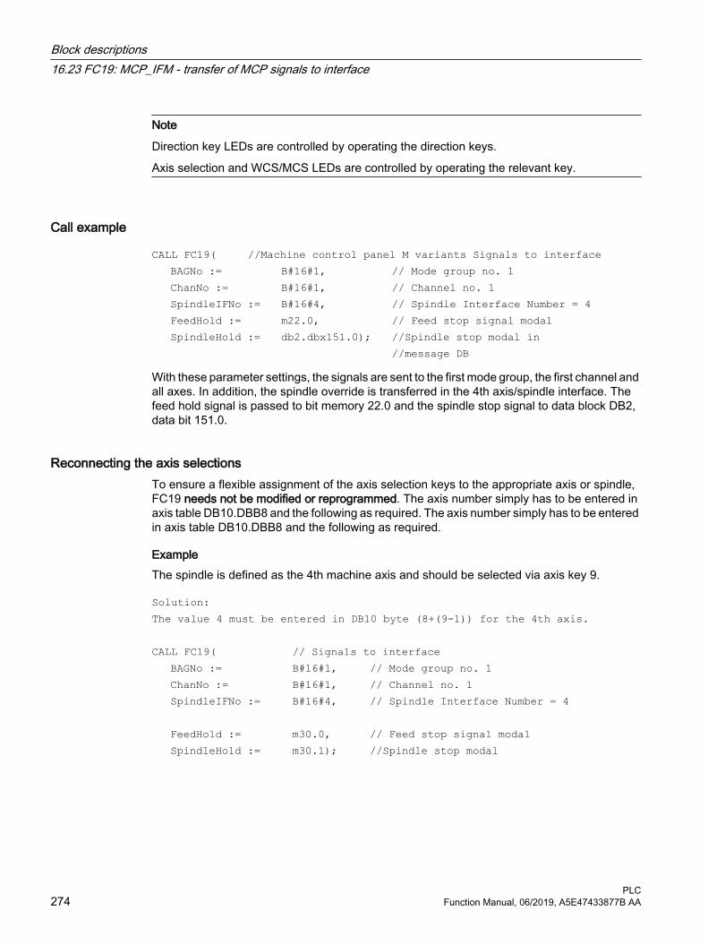
Note
Direction key LEDs are controlled by operating the direction keys.
Axis selection and WCS/MCS LEDs are controlled by operating the relevant key.
Call example
CALL FC19( //Machine control panel M variants Signals to interface BAGNo := B#16#1, // Mode group no. 1 ChanNo := B#16#1, // Channel no. 1 SpindleIFNo := B#16#4, // Spindle Interface Number = 4 FeedHold := m22.0, // Feed stop signal modal SpindleHold := db2.dbx151.0); //Spindle stop modal in //message DB
With these parameter settings, the signals are sent to the first mode group, the first channel and all axes. In addition, the spindle override is transferred in the 4th axis/spindle interface. The feed hold signal is passed to bit memory 22.0 and the spindle stop signal to data block DB2, data bit 151.0.
Reconnecting the axis selectionsTo ensure a flexible assignment of the axis selection keys to the appropriate axis or spindle, FC19 needs not be modified or reprogrammed. The axis number simply has to be entered in axis table DB10.DBB8 and the following as required. The axis number simply has to be entered in axis table DB10.DBB8 and the following as required.
ExampleThe spindle is defined as the 4th machine axis and should be selected via axis key 9.
Solution: The value 4 must be entered in DB10 byte (8+(9-1)) for the 4th axis. CALL FC19( // Signals to interface BAGNo := B#16#1, // Mode group no. 1 ChanNo := B#16#1, // Channel no. 1 SpindleIFNo := B#16#4, // Spindle Interface Number = 4 FeedHold := m30.0, // Feed stop signal modal SpindleHold := m30.1); //Spindle stop modal
Block descriptions16.23 FC19: MCP_IFM - transfer of MCP signals to interface
PLC274 Function Manual, 06/2019, A5E47433877B AA

16.24 FC21: Transfer - data exchange NC/PLC
16.24.1 FunctionBlock FC21 is used to exchange data between the PLC and NC. The data are immediately transferred when FC21 is called – not waiting until the next basic PLC program cycle starts.
The data transfer is activated by calling the block FC21 with parameter "Enable" =1
FunctionsThe block provides the following functions:
● Synchronized action signals: PLC → NC channel
● Synchronized action signals: NC channel → PLC
● Fast data exchange PLC-NC (read function in NC)
● Fast data exchange PLC-NC (write function in NC)
● Update signals to the NC channel
● Update signals to axes (data byte 2 of the user interface)
● Update signals to axes (data byte 4 of the user interface)
16.24.2 Declaration of the function
Declaration of the function
VAR_INPUT Enable : BOOL; Funct : BYTE ; S7Var : ANY ; IVar1 : INT ; IVar2 : INT ;END_VAR VAR_OUTPUT Error : BOOL; ErrCode : INT ;END_VAR
Block descriptions16.24 FC21: Transfer - data exchange NC/PLC
PLCFunction Manual, 06/2019, A5E47433877B AA 275

16.24.3 Explanation of formal parameters
Explanation of formal parameters
Signal Type
Type Value range Description
Enable: I BOOL 0 (FALSE), 1 (TRUE) 1: Transferring dataFunct: I BYTE 1, 2, 3, ... 7 1: Synchronized actions at chan‐
nel2: Synchronized actions from
channel3: Read data4: Write data5: Control signals to channel6: Control signals to axis7: Control signals to axis
S7Var : I ANY S7 data storage area Depends on "Funct"IVAR1: I INT --- Depends on "Funct"IVAR2: I INT --- Depends on "Funct"Error: O BOOL 0 (FALSE), 1 (TRUE) 1: An error is activeErrCode: O INT --- Depends on "Funct"
16.24.4 Function 1, 2: Signals synchronized actions to / from ChannelSynchronized actions can be disabled or enabled by the PLC.
The data area is stored on the user interface in DB21, ... .DBB300 ...307 (to channel) and DB21, ... .DBB308 ...315 (from channel). The parameter "S7Var" is not evaluated for this function, but must be assigned an actual parameter (see call example). The data are transferred to/from the NC as soon as FC21 is processed.
Signal Type Type Value range DescriptionEnable: I BOOL 0 (FALSE), 1 (TRUE) 1: Transferring dataFunct: I BYTE 1, 2 1:
2:to channelfrom channel
S7Var : I ANY S7 data storage area Not usedIVAR1: I INT 1, 2, ... max. channel number Channel numberError: O BOOL 0 (FALSE), 1 (TRUE) 1: An error is activeErrCode: O INT 1, 10 1:
10:"Funct" invalidChannel number invalid
Call example:
FUNCTION FC100: VOIDVAR_TEMP
Block descriptions16.24 FC21: Transfer - data exchange NC/PLC
PLC276 Function Manual, 06/2019, A5E47433877B AA

myAny: ANY ; END_VAR BEGINNETWORK //Deactivate synchronized actions with ID3, ID10 and ID31 in NC channel 1 :SYAK: AUF DB21; SET; S DBX300
.2;//ID3
S DBX301.1;
//ID10
S DBX303.6;
//ID31
L B#16#1;
T MB11; SPA TRAN; //Synchronized actions from NCK channel 1:SYVK: L B#16#2; T MB11; TRAN: CALL FC21 ( Enable := M 10.0, //if TRUE, FC 21 active Funct := MB 11, S7Var := #myAny, //Not used IVAR1 := 1, //Channel no. IVAR2 := 0, Error := M 10.1, ErrCode := MW 12); END_FUNCTION
16.24.5 Function 3, 4: Fast data exchange PLC-NC
GeneralA separate, internal data area is provided as interface to allow the fast exchange of data between the NC and the PLC. The interface encompasses 4096 bytes. PLC access operations (reading/writing) are realized via FC21. The internal structure of the interface is solely defined by the user, and must have precisely the same definition on the NC and PLC sides.
This data can be accessed by the NC program with the commands $A_DBB[x], $A_DBW[x], $A_DBD[x], $A_DBR[x] (further information: List Manual, System Variables).
Block descriptions16.24 FC21: Transfer - data exchange NC/PLC
PLCFunction Manual, 06/2019, A5E47433877B AA 277

The concrete address in the data array is specified by a byte offset (0 to 4095) in parameter "IVAR1". In this case, the alignment must be selected according to the data format, i.e. a DWORD starts at a 4byte limit and a WORD at a 2byte limit. Bytes can be located at any offset within the data field. Individual bits cannot be accessed. FC21 converts them over to a byte access. Data type information and quantity of data are taken from the ANY parameter, transferred via S7Var.
Without additional programming-related measures, data consistency is only ensured for 1 and 2 byte access operations - both from the NCU and from the PLC. For 2-byte consistency this is true only for the data type WORD or INT, but not for the data type BYTE.
In the case of longer data types or transfer of arrays which should be transferred consistently, the semaphore byte must be used in parameter "IVAR2", which can be used by FC21 to determine the validity or consistency of a block. This handling must be supported by the NC, i.e. in the NC program, by writing or deleting the semaphore byte. The semaphore byte is stored in the same data field as the user data.
The semaphore byte is identified by a value between 0 and 4095 in "IVAR2".
The PLC reads and writes to the semaphore byte via FC21 in the same call, in which the user data should be transferred. The PLC programmer only has to define the semaphore variable in the interface. For access from the NC via the NC program, the semaphore mechanism must be programmed using individual instructions according to the flow chart shown below. The sequence is different for reading and writing variables.
Only individual variables or arrays (fields) can be supported directly using the semaphore technique. Transferring structures must be split up into individual jobs. Here, the user must ensure data consistency of this structure by programming the appropriate semaphore mechanism.
If "IVAR2" = -1 is set, data are transferred without a semaphore.
Block descriptions16.24 FC21: Transfer - data exchange NC/PLC
PLC278 Function Manual, 06/2019, A5E47433877B AA

Data exchange with semaphore in PLC (schematic of FC21)
Basic structure in the NC:
Block descriptions16.24 FC21: Transfer - data exchange NC/PLC
PLCFunction Manual, 06/2019, A5E47433877B AA 279
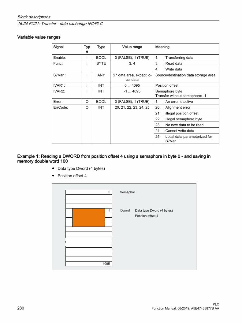
Variable value ranges
Signal Type
Type Value range Meaning
Enable: I BOOL 0 (FALSE), 1 (TRUE) 1: Transferring dataFunct: I BYTE 3, 4 3: Read data
4: Write dataS7Var : I ANY S7 data area, except lo‐
cal dataSource/destination data storage area
IVAR1: I INT 0 ... 4095 Position offsetIVAR2: I INT -1 ... 4095 Semaphore byte
Transfer without semaphore: -1Error: O BOOL 0 (FALSE), 1 (TRUE) 1: An error is activeErrCode: O INT 20, 21, 22, 23, 24, 25 20: Alignment error
21: illegal position offset22: Illegal semaphore byte23: No new data to be read24: Cannot write data25: Local data parameterized for
S7Var
Example 1: Reading a DWORD from position offset 4 using a semaphore in byte 0 - and saving in memory double word 100
● Data type Dword (4 bytes)
● Position offset 4
Block descriptions16.24 FC21: Transfer - data exchange NC/PLC
PLC280 Function Manual, 06/2019, A5E47433877B AA

PLC programming
CALL FC21( Enable := M 10.0, // if TRUE, FC 21 is active Funct := B#16#3, //Read data S7Var := P#M 100.0 DWORD 1, IVAR1 := 4, IVAR2 := 0, Error := M 10.1, ErrCode := MW12); UN M10.1; //Enable while 1, until value is readR M10.0;
Programming the NC with synchronized actions● Writing the data to the PLC - byte 0 serves as semaphore:
ID=1 WHENEVER $A_DBB[0] == 0 DO $A_DBR[4] = $AA_IM[X] $A_DBB[0] = 1
● Reading the data from the PLC - byte 1 serves as semaphore:ID=2 WHENEVER $A_DBB[1] == 1 DO $R1 = $A_DBR[12] $A_DBB[1] = 0
Example 2: Reading a WORD from position offset 8 without semaphore, and saving in memory word 104
CALL FC21( Enable :=M 10.0, // if TRUE, FC 21 is active Funct :=B#16#3, //Read data S7Var :=P#M 104.0 WORD 1, IVAR1 :=8, IVAR2 :=-1, Error :=M 10.1, ErrCode :=MW12);
16.24.6 Function 5: Update control signals to channelThe purpose of this function is to transmit important control signals at high speed in between cyclic data transfers. Data bytes 6 and 7 of user interfaces DB21, ... are transferred to the NC. The channel is specified in parameter "IVAR1". This enable, for example, the feed disable, read-in disable to be transferred outside of the PLC cycle.
Signal Type
Type Value range Description
Enable: I BOOL 0 (FALSE), 1 (TRUE) 1: Transferring dataFunct: I BYTE 5 5: Control signals to channelS7Var : I ANY S7 data storage area Not usedIVAR1: I INT 1. Maxchannel Channel numberError: O BOOL 0 (FALSE), 1 (TRUE) 1: An error is active
Block descriptions16.24 FC21: Transfer - data exchange NC/PLC
PLCFunction Manual, 06/2019, A5E47433877B AA 281

Signal Type
Type Value range Description
ErrCode: O INT 1, 10 1: "Funct" invalid10: Channel no. invalid
16.24.7 Function 6: Update control signals to axesThe purpose of function 6 is to transmit important control signals at high speed in between cyclic data transfers. The data byte 2 of application interface DB31, ... is transferred to the NC. The transfer is performed for all activated axes. This allows the controller enable to be transferred outside the PLC cycle, for example.
Signal Type
Type Value range Description
Enable: I BOOL 0 (FALSE), 1 (TRUE) 1: Transferring dataFunct: I BYTE 6 6: Control signals to axesS7Var : I ANY S7 data storage area Not usedIVAR1: I INT 0 Error: O BOOL 0 (FALSE), 1 (TRUE) 1: An error is activeErrCode: O INT 1 1: "Funct" invalid
16.24.8 Function 7: Update control signals to axesThe purpose of function 7 is to transmit important control signals at high speed in between cyclic data transfers. The data byte 4 of application interface DB31, ... is transferred to the NC. The transfer is performed for all activated axes. This enables, for example, the feed stop to be transferred outside the PLC cycle.
Signal Type
Type Value range Description
Enable: I BOOL 0 (FALSE), 1 (TRUE) Funct: I BYTE 7 7: Control signals to axesS7Var : I ANY S7 data storage area Not usedIVAR1: I INT 0 Error: O BOOL 0 (FALSE), 1 (TRUE) 1: An error is activeErrCode: O INT 1 1: "Funct" invalid
Block descriptions16.24 FC21: Transfer - data exchange NC/PLC
PLC282 Function Manual, 06/2019, A5E47433877B AA

16.25 FC22: TM_DIR - direction selection for tool management
NOTICE
Use
Block FC22 "TM_DIR" may only be used in conjunction with the tool management.
FunctionReferred to the location numbers, e.g. a tool magazine or revolver (indexing axis) block FC22 "TM_DIR" supplies the shortest path and direction of motion for positioning, based on the target and current position.
Outputs● Input FC22: "Start" = 1 ⇒ the outputs are cyclically updated.
● Input FC22: "Start" = 0 ⇒ the outputs are undefined.
Special positioningFor direction selection with special positioning (input FC22: "Offset" > 0) a new target position is calculated from the target position, the offset for special positioning as well as the number of magazines locations:
New_target position = ( target position - ( special position -1 ) ) neg. MODULO number_of_magazine locations
The new target position corresponds to the location number at which the magazine must be positioned so that the target position requested by the user corresponds to the location number of the special position.
The directional optimization is active both with and without special positioning.
CallThe block must be called once with the appropriate parameter settings for each magazine.
Further information● Further PI services for tool management:
– FB4: PI_SERV - request PI service (Page 173)
– FC7: TM_REV - transfer block for tool change with revolver (Page 234)
– FC8: TM_TRANS - transfer block for tool management (Page 238)
● Function Manual, Tool Management
Declaration of the function
FUNCTION FC22: VOID// NAME: TM_DIRVAR_INPUT
Block descriptions16.25 FC22: TM_DIR - direction selection for tool management
PLCFunction Manual, 06/2019, A5E47433877B AA 283

MagNo: INT; ReqPos: INT; ActPos: INT; Offset: BYTE ; Start : BOOL;END_VAR VAR_OUTPUT Cw: BOOL; Ccw: BOOL; InPos : BOOL; Diff: INT; Error : BOOL;END_VARBEGINEND_FUNCTION
Description of formal parameters
Signal Type
Type Value range Meaning
MagNo: I INT 1, 2, 3, ... Magazine numberReqPos: I INT 1, 2, 3, ... Target position (magazine location
number)ActPos: I INT 1, 2, 3, ... Actual position (magazine location
number)Offset: I BYTE 0, 1, 2, ... Offset for special positioningStart: I BOOL 0 (FALSE), 1 (TRUE) 1 = start of calculationCw: O BOOL 0 (FALSE), 1 (TRUE) 1 = Move magazine clockwiseCcw: O BOOL 0 (FALSE), 1 (TRUE) 1 = Move magazine
counterclockwiseInPos: O BOOL 0 (FALSE), 1 (TRUE) 1 = In positionDiff: O INT 0, 1, 2, ... Absolute value of the differential
path (shortest path)
Error: O BOOL 0 (FALSE), 1 (TRUE) 1 = error
Call example
CALL FC22( // Tool management direction selection // Inputs MagNo := 2, // Magazine number ReqPos := mw 20, //Target position ActPos := mw 22, // Current position Offset := b#16#0, // Offset for special positioning
Block descriptions16.25 FC22: TM_DIR - direction selection for tool management
PLC284 Function Manual, 06/2019, A5E47433877B AA

Start := m 30.4, // Start trigger // Outputs Cw := m 30.0, // Move magazine clockwise Ccw := m 30.1, // Move magazine counterclockwise InPos := m 30.2, // Magazine in position Diff := mw 32, // Differential path Error := m30.3 // Error has occurred );
16.26 FC24: MCP_IFM2 - transferring MCP signals to the interface
Function Block FC24 "MCP_IFM2" (M variant, e.g. MCP 310) is used for transferring data from the machine control panel to the NC/PLC interface:
● Modes
● Axis selections
● WCS/MCS switchover
● Traversing keys
● Overrides or override simulation signals
● Key-operated switch position
The following specifications apply to the feedrate override, axis travel keys and INC keys depending on the active mode or on the coordinate system selected:
● Feedrate override:
– The feedrate override is transferred to the interface of the selected channel and to the interface of the axes.
– The feedrate override signals are transferred to the NC channel in addition to the "Rapid traverse override" (DBB 5) interface byte if the "Feedrate override for rapid traverse effective" HMI signal is set (exception: Switch setting "Zero"). "Rapid traverse override effective" is also set with this HMI signal.
● Machine functions for INC and axis travel keys:
– When the MCS is selected, the signals are transferred to the interface of the selected machine axis.
– When the WCS is selected, the signals are transferred to the geometry axis interface of the parameterized channel.
– When the system is switched between MCS and WCS, the active axes are generally deselected.
The associated LEDs on the machine control panel are derived from the acknowledgments from the relevant selections.
Block descriptions16.26 FC24: MCP_IFM2 - transferring MCP signals to the interface
PLCFunction Manual, 06/2019, A5E47433877B AA 285

Feedrate and spindle Start/Stop are not transferred to the interface, but output modally as a "FeedHold" or "SpindleHold" signal. The user can link these signals to other signals leading to a feed or spindle stop (this can be implemented, e.g. using the appropriate input signals in FC10: AL_MSG). The associated LEDs are activated at the same time.
The spindle direction (+, -) is not switched directly either, but made available as output parameter "SpindleDir". permitting, for example, FC18 to be parameterized. A spindle enable signal is also switched via parameter "SpindleHold". One possible method of moving a spindle directly is to preselect it as an axis so that it can be traversed via (axis) direction keys.
If the machine control panel fails, the signals it outputs are preset to zero; this also applies to "FeedHold" and "SpindleHold" output signals.
FC24 or also FC19, FC25, FC26 can be called a multiple number of times in a single PLC cycle. In this case, the first call in the cycle drives the LED displays. Furthermore, all actions of the parameterized block are carried out in the first call. In the following calls, only a reduced level of processing of the channel and mode group interface takes place. The geometry axes are supplied with directional data only in the first block call in the cycle.
Single block processing can be selected/deselected only in the first call in the cycle.
The second machine control panel can be processed if parameter "ModeGroupNo" has been increased by B#16#10. When parameterizing, the HHU number is contained in the lower nibble (lower 4 bits).
"BAGNo" = 0 or B#16#10 ⇒ mode group signals are not processed.
"ChanNo" = 0 ⇒ no processing of the channel signals.
The INC selections are transferred to the mode group interface. The activation for this specification is done via the DB10.DBX57.0 (INC inputs in BAG area active) through this block once after power up.
Furthermore, two machine control panels can be handled in parallel by this block. The block call for the 2nd machine control panel in OB1 cycle must be set after the call of the 1st MCP. Support for two MCPs is provided in the control panel blocks up to certain limits (support is not provided as standard for mutual interlocking of axis selections with identical assignments on two MCPs).
Key-operated switch positionAs of software version 4.5 SP2, the key-operated switch signals in the FC24 are also transferred to the user interface (DBX56.5 to 7). This transfer is made independent of whether a keyswitch is mounted on the MCP.
Note
For further information see "FC19: MCP_IFM - transfer of MCP signals to interface (Page 267)".
Flexible axis configurationIt is possible to be flexible in the assignment of axis selections or direction keys for machine axis numbers.
Better support is now provided by the MCP blocks for the use of two MCPs, which are to run in parallel, in particular for an application using two channels and two mode groups. Note that the
Block descriptions16.26 FC24: MCP_IFM2 - transferring MCP signals to the interface
PLC286 Function Manual, 06/2019, A5E47433877B AA

axis-numbers are also specified in the parameterized mode group number of the MCP block in the axis tables of the relevant MCP.
To provide this flexibility, tables for axis numbers are stored in DB10. For the 1st machine control panel (MCP) the table starts at byte 8 (symbolic name: MCP1AxisTbl[1..22]) and for the second machine control panel (MCP) starting at byte 32 (symbolic name: MCP2AxisTbl[1..22]). The machine axis numbers must be entered byte by byte here. It is permissible to enter a value of 0 in the axis table. Checks are not made to find illegal axis numbers, meaning that false entries can lead to a PLC Stop.
For FC24, the maximum possible number of axis selections can also be restricted. This upper limit is set for the first machine control panel in DB10.DBW30 (symbolic name: MCP1MaxAxis) or for the second machine control panel in DB10.DBW54 (symbolic name: MCP2MaxAxis) for the respective MCP.
The default setting is 0, corresponding to the maximum number of configured axes. The axis numbers and the limit can also be adapted dynamically. Afterwards, a new axis must be selected for FC24. Axis numbers may not be switched over while the axes are traversing the relevant direction keys. The compatibility mode is preset with axis numbers 1 to 6 for both MCPs and restricted to the configured number of axes.
Axis selection from the HMIIn addition to the 6 axis selection keys of the MCP, the active axis can also be selected in the HMI.
If an axis is being selected from the HMI, then no axes can be traversed using the direction keys. Axis selection from the HMI is then only adopted for the MCP if the selected channel in the HMI correlates with that at FC25. With axis selection from the HMI, an initial attempt is made as with axis selection using the axis selection keys of the MCP, to find an assignment between the selected axis number and the actual machine axis in the axis table of the NC-DB, refer to section "Flexible axis configuration".
This means that when an axis is selected from the HMI, the same machine axis is selected as if the corresponding axis selection key of the MCP had been selected. If an assignment is not possible, then the axis number selected from the HMI is directly used as machine axis. As a consequence it is possible to select axes that cannot be selected via the MCP.
Single block modePressing the single block key activates the single block mode, and if the key is pressed again, the single block mode is deactivated. If the mode is called several times for one MCP, the block transfers single block mode state from the channel of the first call to the channels of the subsequent calls.
Declaration of the function
FUNCTION FC24: VOID// NAME: MCP_IFM2 VAR_INPUT BAGNo : BYTE ;
Block descriptions16.26 FC24: MCP_IFM2 - transferring MCP signals to the interface
PLCFunction Manual, 06/2019, A5E47433877B AA 287

ChanNo: BYTE ; SpindleIFNo: BYTE ;END_VAR VAR_OUTPUT FeedHold : BOOL; SpindleHold : BOOL; SpindleDir: BOOL;END_VAR BEGINEND_FUNCTION
Description of formal parameters
Signal Type
Type Value range Meaning
BAGNo : I BYTE B#16#00 - B#16#0A 1st MCP: Number of mode group to which the mode signals are transferred
B#16#10 - B#16#1A 2nd MCP: Number of mode group to which the mode signals are transferred
ChanNo: I BYTE B#16#00 - B#16#0A Number of the channel to which the channel signals are transferred
SpindleIFNo: I BYTE 0 - 31 (B#16#1F)
Number of the axis/spindle to which the spin‐dle data is transferred (number of the associ‐ated machine axis)
FeedHold : O BOOL 0 (FALSE), 1 (TRUE) Feed stop from MCP, modalSpindleHold : O BOOL 0 (FALSE), 1 (TRUE) Spindle stop from MCP, modalSpindleDir: O BOOL 0 (FALSE), 1 (TRUE) Direction of spindle rotation
0: Direction of rotation + (left)1: Direction of rotation - (right)
Call example
CALL FC24( // Slimline machine control panel M variant
// Signals to interface BAGNo := B#16#1, // Mode group no. 1 ChanNo := B#16#1, // Channel no. 1 SpindleIFNo :
=B#16#4, // Spindle Interface Number = 4
FeedHold := m22.0, // Feed stop signal modal SpindleHold :
=db2.dbx151.0, // Spindle stop modal in message data block
SpindleDir:= m22.1); // Spindle direction return
Block descriptions16.26 FC24: MCP_IFM2 - transferring MCP signals to the interface
PLC288 Function Manual, 06/2019, A5E47433877B AA

With these parameter settings, the signals are sent to the first mode group, the first channel and all axes. In addition, the spindle override is transferred in the 4th axis/spindle interface. The feed hold signal is passed to bit memory 22.0 and the spindle stop signal to data block DB2, data bit 151.0. The spindle direction feedback signal supplied via parameter "SpindleDir" can be used as a direction input for an additional FC18 call.
16.27 FC25: MCP_IFT - transfer of MCP/OP signals to interface
Function Block FC25 "MCP_IFT" (T variant, e.g. MCP 483) is used for transferring data from the machine control panel to the NC/PLC interface:
● Modes
● Direction keys of four axes
● WCS/MCS switchover
● Overrides
● Keyswitch
The following specifications apply to the feedrate override, axis travel keys and INC keys depending on the active mode or on the coordinate system selected:
● Feedrate override:
– The feedrate override is transferred to the interface of the selected channel and to the interface of the axes.
– The feedrate override signals are transferred to the NC channel in addition to the "Rapid traverse override" (DBB 5) interface byte if the "Feedrate override for rapid traverse effective" HMI signal is set (exception: Switch setting "Zero"). "Rapid traverse override effective" is also set with this HMI signal.
● Machine functions for INC and axis travel keys:
– When the MCS is selected, the signals are transferred to the interface of the selected machine axis.
– When the WCS is selected, the signals are transferred to the geometry axis interface of the parameterized channel.
The associated LEDs on the machine control panel derived from the acknowledgments of the relevant selections.
Feedrate and spindle Start/Stop are not transferred to the interface, but output modally as a "FeedHold" or "SpindleHold" signal. The user can link these signals to other signals leading to a feed or spindle stop (this can be implemented, e.g. using the appropriate input signals in FC10: AL_MSG). The associated LEDs are activated at the same time.
If the machine control panel fails, the signals it outputs are preset to zero; this also applies to "FeedHold" and "SpindleHold" output signals.
FC25 or also FC19, FC24, FC26 can be called a multiple number of times in a single PLC cycle. In this case, the first call in the cycle drives the LED displays. Furthermore, all actions of the parameterized block are carried out in the first call. In the following calls, only a reduced level
Block descriptions16.27 FC25: MCP_IFT - transfer of MCP/OP signals to interface
PLCFunction Manual, 06/2019, A5E47433877B AA 289

of processing of the channel and mode group interface takes place. The geometry axes are supplied with directional data only in the first block call in the cycle.
Single block processing can be selected/deselected only in the first cycle.
The second machine control panel can be processed if parameter "ModeGroupNo" has been increased by B#16#10. When parameterizing, the HHU number is contained in the lower nibble (lower 4 bits).
"BAGNo" = 0 or B#16#10 ⇒ mode group signals are not processed.
"ChanNo" = 0 ⇒ no processing of the channel signals.
Flexible axis configurationIt is possible to be flexible in the assignment of axis selections or direction keys for machine axis numbers.
Support is now provided by the MCP blocks for the use of two MCPs, which are operated simultaneously, in particular for an application using two channels and two mode groups. The block call for the second machine control panel in OB1 cycle must be set after the call of the 1st MCP. Note that the axis numbers are also specified in the parameterized mode group number of the MCP block in the axis tables of the relevant MCP.
To provide this flexibility, tables for axis numbers are stored in DB10. For the 1st machine control panel (MCP), the table starts at byte 8 (symbolic name: MCP1AxisTbl[1..22]) and for the 2nd machine control panel (MCP), from byte 32 (symbolic name: MCP2AxisTbl[1..22]). The machine axis numbers are entered here byte-by-byte. It is permissible to enter a value of 0 in the axis table. Checks are not made to find illegal axis numbers, meaning that false entries can lead to a PLC Stop.
The restriction of the possible number of axes at FC25 is realized using the 0-values in the axis table. The axis numbers can also be adapted dynamically. During the manual traversing of axes using the direction keys, the axis numbers must not be switched over. The compatibility mode is preset with axis numbers 1 to 4 for both MCPs and restricted to the configured number of axes.
Note
For further information see "FC19: MCP_IFM - transfer of MCP signals to interface (Page 267) ".
Declaration of the function
FUNCTION FC25: VOID// NAME: MCP_IFT VAR_INPUT BAGNo : BYTE ; ChanNo: BYTE ; SpindleIFNo: BYTE ;END_VAR
Block descriptions16.27 FC25: MCP_IFT - transfer of MCP/OP signals to interface
PLC290 Function Manual, 06/2019, A5E47433877B AA

VAR_OUTPUT FeedHold : BOOL; SpindleHold : BOOL;END_VAR BEGINEND_FUNCTION
Description of formal parameters
Signal Type
Type Value range Meaning
BAGNo : I BYTE B#16#00 - B#16#0A 1st MCP: Number of mode group to which the mode signals are transferred
B#16#10 - B#16#1A 2nd MCP: Number of mode group to which the mode signals are transferred
ChanNo: I BYTE B#16#00 - B#16#0A Number of the channel to which the channel signals are sent
SpindleIFNo: I BYTE B#16#00 - B#16#1F Number of the axis/spindle to which the spin‐dle data is transferred (number of the associ‐ated machine axis)
FeedHold : O BOOL 0 (FALSE), 1 (TRUE) Feed stop from MCP, modalSpindleHold : O BOOL 0 (FALSE), 1 (TRUE) Spindle stop from MCP, modal
Call exampleWith this parameter assignment example, the signals are sent to the 1st mode group, the 1st channel and all axes. The spindle override is transferred to the 4th axis/spindle. Feed stop is sent to bit memory 22.0 and spindle stop is sent to the data block DB2, DBX151.0.
CALL FC25( //Machine control panel T variants // Signals to interface BAGNo := B#16#1, // Mode group no. 1 ChanNo := B#16#1, // Channel no. 1 SpindleIFNo := B#16#4, // Spindle Interface Number = 4 FeedHold := m22.0, // Feed stop signal modal SpindleHold := db2.dbx151.0)
;// Spindle stop modal in message data block
Block descriptions16.27 FC25: MCP_IFT - transfer of MCP/OP signals to interface
PLCFunction Manual, 06/2019, A5E47433877B AA 291

16.28 FC26: HPU_MCP - Transfer of the HT 8/HT 10 signals to the interface
General description of functions The function FC26 "HPU_MCP (machine control panel signals of the handheld unit HT 8)" transfers the HT 8-specific or HT 10-specific signals of the following functions between the HT 8 or HT 10 input/output data range parameterized in the function block FB1 (parameter: MCPxIn and MCPxOut) and the NC/PLC-interface:
● Modes
● Machine function INC
● Coordinate system WCS or MCS
● Axial traverse key
● Axis selection
● Feedrate override
● Rapid traverse override
● Keyswitch information
NoteMode switchover through HT 8 and/or HMI
The function FC2 "GP_HP Basic program, cyclic part" transfers the signals of the mode switchover in such a way that an alternative selection from MCP of HT 8 and of the HMI is possible. The transfer of the HMI signals to the NC/PLC interface can also be deactivated in the function block FB1 with the parameter "MMCToIF" = FALSE .Active axes
Using HT 8 a maximum of 6 axes can be addressed at the same time. The selection of the axes is to be realized by the user/machine manufacturer in the PLC user program.
Bit 6.7 in the input image is used to make a differentiation between the HT 8 and HT 10. This bit is set for an HT 10.
Flexible axis configuration for the HT 8The function FC26 enables a flexible assignment of the machine axes to the traversing keys or to the axis selection. 2 tables are available in DB10 for this purpose:
● Machine axis table, 1st MCP: DB10.DBB8 to DBB13 (Table of the machine axis number)Symbolic name: MCP1AxisTbl[1..22]
● Machine axis table, 2nd MCP: DB10.DBB32 to DBB37 (Table of the machine axis number) Symbolic name: MCP2AxisTbl[1..22]
In the tables the axis numbers n (with n = 1, 2, ...) of the active machine axis are to be entered byte-wise. The value 0 must be entered in the unused table locations.
Block descriptions16.28 FC26: HPU_MCP - Transfer of the HT 8/HT 10 signals to the interface
PLC292 Function Manual, 06/2019, A5E47433877B AA

The table length can be specified to the FC26:
● 1st MCP: DB10.DBB30 (upper limit of the machine axis table)
● 2nd MCP: DB10.DBB54 (upper limit of the machine axis table)
A value of 4, for example, means that FC26 takes into account only the first 4 table entries or machine axes. The maximum value for the FC26 is 6. For a value of 0 or values greater than 6 the maximum value is taken implicitly.
Note
Please note the following constraints:● A check of the permissible machine axis numbers is not done. Invalid machine axis numbers
can lead to a PLC stop.● The machine axis numbers can be changed dynamically. The table may not be written, if
currently a machine axis is being moved via a traversing key.
Flexible axis configuration for the HT 10Contrary to the HT 8, the HT 10 only has one plus and one minus key for traversing. There is also a rapid key for rapid traversing. The active axis, to which these traversing signals refer, must be selected at the HMI.
If an axis is being selected from the HMI, then no axis can be traversed using the direction keys. Axis selection from the HMI is then only adopted for the MCP if the selected channel in the HMI correlates with that at FC26.
If FC26 is called for an HT 10 with ChanNo <= 0, no axes can be traversed as the current axis cannot be determined from the channel DB.
Declaration of the function
FUNCTION FC26: VOID// NAME: HPU_MCP VAR_INPUT BAGNo : BYTE ;
ChanNo: BYTE ;END_VAR BEGINEND_FUNCTION
Block descriptions16.28 FC26: HPU_MCP - Transfer of the HT 8/HT 10 signals to the interface
PLCFunction Manual, 06/2019, A5E47433877B AA 293

Description of formal parameters
Signal Type
Type Value range Meaning
BAGNo : I BYTE B#16#00 - B#16#0A 1st MCP: Number of mode group to which the mode signals are transferred
B#16#10 - B#16#1A 2nd MCP: Number of mode group to which the mode signals are transferred
ChanNo: I BYTE B#16#00 - B#16#0A Number of the channel to which the channel sig‐nals are transferred0: No transfer of channel signals(and thus no axis can be traversed in JOG mode for HT 10)
Call examplesCalling FC26 for the first MCP, the first mode group and the first channel of the NC.
CALL FC26( //Machine control panel of the HT 8 BAGNo := B#16#01, //1.MCP, 1.BAG ChanNo := B#16#01); //Channel 1
Calling FC26 for the second MCP, the second mode group and the third channel of the NC.
CALL FC26( //Machine control panel of the HT 8 BAGNo := B#16#12, //2.MCP, 2.BAG ChanNo := B#16#03 ); //Channel 3
Transfer of the traversing key signals depending upon the active coordinate systemThe traversing key signals for 6 axes lie in the HT 8 input data area below:
● EB n + 2, Bit 0 - Bit 5 (positive traversing direction)
● EB n + 3, Bit 0 - Bit 5 (negative traversing direction)
The switchover of the coordinate system is done via the input signal:
● EB n + 0, Bit 0 (MCS/WCS)
The input signal is evaluated in FC26 with the help of the edge trigger flag. The active coordinate system is shown in the following output signal:
● AB n + 0, Bit 0 (MCS/WCKS) with 0 = MCS, 1 = WCS
In case of active MCS the traversing key signals of the axes 1 - 6 are transferred in the axis-specific interfaces (DB31, ... .DBX4.6 and DBX4.7 (traversing key +/-)) of the axes specified in the machine axis tables (DB10.DBB8 to DBB13 or DBB32 to DBB37).
Block descriptions16.28 FC26: HPU_MCP - Transfer of the HT 8/HT 10 signals to the interface
PLC294 Function Manual, 06/2019, A5E47433877B AA

For HT 8 with active WCS, it is assumed that the axes 1 - 3 of the machine axis table are geometry axes. For the traverse key signals with HT 8, the following applies:
● The traverse key signals of axes 1 - 3 (EB n + 2 / 3, bit 0 - bit 2) are transferred into the interface of the geometry axes in DB21, ... .DBB12 + (n * 4), with n = 0, 1, 2), bit 6 and bit 7 (traverse keys +/-) of the channel specified with parameter "ChanNo". The assignment of the traversing key signals of axes 1, 2 and 3 to the geometric axes 1, 2 and 3 of the channel is permanent and may not be changed.
● The traverse key signals of axes 4 - 6 (EB n + 2 / 3, bit 3 - bit 5) are transferred into the axis-specific interfaces (DB31, ... .DBX4.6 and DBX4.7 (traverse keys +/-)) of axes 4 - 6 entered in the machine axis table (DB10.DBB11 to DBB13 or DBB35 to DBB37).
For HT 10, only one geometry axis which was selected from the HMI can be traversed respectively.
The axis traverse signals (+/- and rapid traverse) for HT 10 relate to a machine axis or a geometry axis, depending on which axis was selected in the HMI and whether WCS or MCS is active. Refer also to "Flexible axis configuration for HT 10".
No traversing of machine axes in WCSIn case of active WCS (AB n + 0, Bit 0 = 1) the traversing of the machine axes can be locked. For this, the following output signals are to be set in the PLC user program:
● AB n + 3, Bit 7 = 1 (For WCS: no machine axes)Requirement to the FC26, not to transfer any traversing key signals for the machine axes. The traversing key signals for the axes 1 - 3 of the machine axis table are transferred to the geometric axes 1 - 3 of the specified channel. The traversing key signals for the axes 4 - 6 of the machine axis table are not transferred.
● AB n + 2, Bit 6 (axes 7 - n selected)Requirement to the FC26 not to transfer any traversing key signals, since the axes 1 - 6 of the machine axis table are switched over. The axes 1 - 3 are thus not geometric axes, but instead also machine axes.
Feedrate overrideThe value of the HT 8 override switch is transferred as feedrate override in the channel-specific interface DB21, ... .DBB4 (feedrate override) of the programmed channel (parameter: "ChanNo") and in the axis-specific interfaces DB31, ... .DBB0 (feedrate override) of the axes programmed in the table DB10.DBB8 to DBB13 (machine axis number).
Rapid traverse overrideIf for the programmed channel (parameter: "ChanNo") the signal DB21, ... .DBX25.3 = 1 (feedrate override for rapid traverse) is set, the value of the HT 8 override switch is sent as a rapid traverse override to its channel-specific interface in DB21, ... .DBB5 (rapid traverse override) and the signal DB21, ... .DBX6.6 = 1 (rapid traverse override active) is also set.
Block descriptions16.28 FC26: HPU_MCP - Transfer of the HT 8/HT 10 signals to the interface
PLCFunction Manual, 06/2019, A5E47433877B AA 295

Machine function INCThe HT 8 signals of the machine function INC are transferred differently depending upon the active coordinate system MCS or WCS:
● Active coordinate system: MCSThe selected machine function INC is transferred for all 6 axes in the axis-specific interfaces in DB31, ... .DBX5.0 to DBX5.5 (machine function) of the axes programmed in the table in DB10.DBB8 to DBB13 (machine axis numbers) .
● Active coordinate system: WCSFor the axes 1 to 3 the signals of the machine function INC are transferred in the channel-specific. Interface in DB21, ... .DBX13.0 to DBX13.5 (machine function) of the programmed channel (Parameter: "ChanNo").For the axes 4 to 6 the signals of the machine function INC are transferred in the channel-specific. interfaces in DB31, ... .DBX5.0 to DBX5.5 (machine function) of the axes programmed in the table in DB10.DBB11 to DBB13 (machine axis numbers).
The selection signals of the INC machine functions are transferred in the mode group-specific interface DB11.DBB 2 + (n * 20), bit 0 to bit 5 (with n = 0, 1, 2, ...). The FC26 informs the NC about the activation of the mode group interface for the INC machine functions once after power-up with DB10.DBX57.0 (INC inputs active in the mode group area).
Handwheel selectionThe hand-wheel selection signals are evaluated by HMI and transferred to the corresponding NC/PLC interface signals of the machine or geometric axes:
● Geometry axes: DB21, ... DBB 12 + (n * 4), bit 0 to bit 2 (with n = 0, 1, 2)
● Machine axes: DB31, ... .DBX4.0 to DBX4.2
Requirement: FB1 parameters: "HWheelMMC" = TRUE
Multiple call in one PLC cycleFC26 can be called a multiple number of times in a single PLC cycle. Upon the first call in the PLC cycle:
● All actions of the parameterized blocks are executed
● The LED signals are written in the output area
● In case of selected WCS, the traversing key signals of the geometric axes are written
● The signals for the selection and deselection of the individual block are processed
When FC26 is called more often, then the channel and mode group interface are processed at a reduced rate.
Block descriptions16.28 FC26: HPU_MCP - Transfer of the HT 8/HT 10 signals to the interface
PLC296 Function Manual, 06/2019, A5E47433877B AA

Processing of two MCPIf the function FC26 is called twice for two MCP in the cyclic sequence of the PLC program (organization block OB1), the call for the second MCP must be made after the call for the first MCP.
Note
If an axis can be traversed from two MCP, then the implementation of a mutual interlocking is the responsibility of the user (machine manufacturer).
Failure of the MCP of the HT 8 or HT 10If the MCP of HT 8 or HT 10 fails, all input signals are set to the value 0.
16.28.1 Overview of the NC/PLC interface signals of HT 8
Operating modes and machine functions
Source: MCP Target: Programmed mode group (Parameter BAGNo) Display for BAG 1
AUTOMATIC DB11.DBX0.0MDI DB11.DBX0.1JOG DB11.DBX0.2REPOS DB11.DBX1.1REF DB11.DBX1.2TEACH IN DB11.DBX1.0INC 1 ... 10 000, INC Var. DB11.DBX2.0 - DBX 2.5
Traversing keys and rapid traverse override
Source: MCP Target: Geometry axes of the prog. channel (parameter: ChanNo)Traversing key + DB21, ... .DBX12.7Traversing key - DB21, ... .DBX12.6Rapid traverse override DB21, ... .DBX12.5Traversing key + DB21, ... .DBX16.7Traversing key - DB21, ... .DBX16.6Rapid traverse override DB21, ... .DBX16.5Traversing key + DB21, ... .DBX20.7Traversing key - DB21, ... .DBX20.6Rapid traverse override DB21, ... .DBX20.5
Block descriptions16.28 FC26: HPU_MCP - Transfer of the HT 8/HT 10 signals to the interface
PLCFunction Manual, 06/2019, A5E47433877B AA 297

Source: MCP Target: Prog. Axes according to the table in DB10, DBB8 - 13 (1st MCP) or DBB32 - 37 (2nd MCP)
Traversing key + DB31, ... .DBX4.7Traversing key - DB31, ... .DBX4.6Rapid traverse override DB31, ... .DBX4.5; HT 10 only
Override
Source: MCP Target: Programmed channel (Parameter: ChanNo)Feedrate override DB21, ... .DBB4
Source: MCP Target: Prog. Axes according to the table in DB10, DBB8 - 13 (1st MCP) or DBB32 - 37 (2nd MCP)
Feedrate override DB31, ... .DBB0
Channel signals
Source: MCP Target: Programmed channel (Parameter: ChanNo)NC start DB21, ... .DBX7.1NC stop DB21, ... .DBX7.3RESET DB21, ... .DBX7.7Single block DB21, ... .DBX0.4
Note
Unlike other MCP models, the HT 8 does not indicate the feedback messages via output signals with LEDs.
Output signals from the axis traversing key pairs are not switched.
Output signals from the WCS and single block are switched after the keys have been pressed.
The output signal from Reset is not switched. (HT 8)
The LEDs of the direction keys +/- and rapid traverse are controlled by pressing the keys. (HT 10)
Block descriptions16.28 FC26: HPU_MCP - Transfer of the HT 8/HT 10 signals to the interface
PLC298 Function Manual, 06/2019, A5E47433877B AA
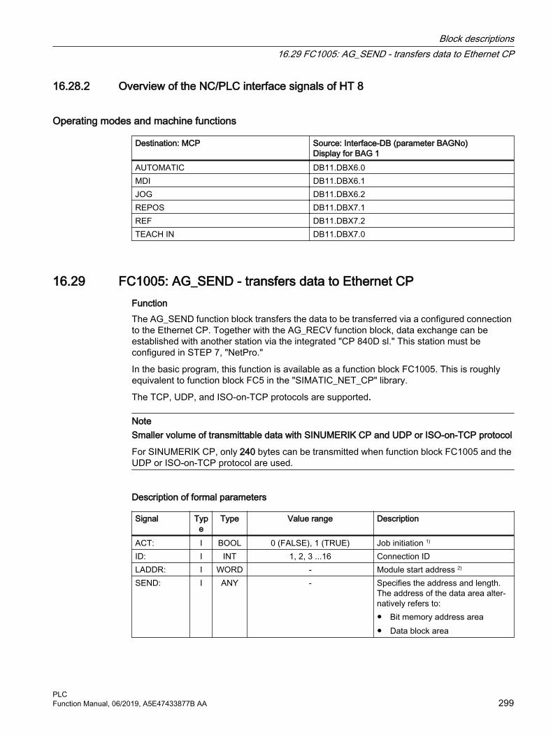
16.28.2 Overview of the NC/PLC interface signals of HT 8
Operating modes and machine functions
Destination: MCP Source: Interface-DB (parameter BAGNo) Display for BAG 1
AUTOMATIC DB11.DBX6.0MDI DB11.DBX6.1JOG DB11.DBX6.2REPOS DB11.DBX7.1REF DB11.DBX7.2TEACH IN DB11.DBX7.0
16.29 FC1005: AG_SEND - transfers data to Ethernet CPFunction The AG_SEND function block transfers the data to be transferred via a configured connection to the Ethernet CP. Together with the AG_RECV function block, data exchange can be established with another station via the integrated "CP 840D sl." This station must be configured in STEP 7, "NetPro."
In the basic program, this function is available as a function block FC1005. This is roughly equivalent to function block FC5 in the "SIMATIC_NET_CP" library.
The TCP, UDP, and ISO-on-TCP protocols are supported.
NoteSmaller volume of transmittable data with SINUMERIK CP and UDP or ISO-on-TCP protocol
For SINUMERIK CP, only 240 bytes can be transmitted when function block FC1005 and the UDP or ISO-on-TCP protocol are used.
Description of formal parameters
Signal Type
Type Value range Description
ACT: I BOOL 0 (FALSE), 1 (TRUE) Job initiation 1)
ID: I INT 1, 2, 3 ...16 Connection IDLADDR: I WORD - Module start address 2)
SEND: I ANY - Specifies the address and length. The address of the data area alter‐natively refers to:● Bit memory address area● Data block area
Block descriptions16.29 FC1005: AG_SEND - transfers data to Ethernet CP
PLCFunction Manual, 06/2019, A5E47433877B AA 299

Signal Type
Type Value range Description
LEN: I INT TCP: 1, 2, ... 8192UDP: 1, 2, ... 240
ISO-on-TCP: 1, 2. ... 240
Number of bytes that are transmitted
DONE: O BOOL 0 (FALSE), 1 (TRUE) 0: Job running1: Job executed
ERROR: O BOOL 0 (FALSE), 1 (TRUE) 0: No error1: An error is active
STATUS: O WORD - Status display1) Parameter ACT must be TRUE long enough until the following applies: (DONE == 1) OR (ERROR == 1)2) For SINUMERIK 840D sl: Parameter LADDR := W#16#8110
DocumentationA detailed module description can be found in:
● SINUMERIK user interfaces: Online help
● SIMATIC Programming Manual: Program blocks for SIMATIC NET S7-CPsChapter: "Program blocks for Industrial Ethernet" > "Program blocks for open communication services (SEND/RECEIVE interface)" > "AG_SEND / AG_LSEND / AG_SSEND"
16.30 FC1006: AG_RECV - receives data from the Ethernet CPFunction The function block AG_RECV receives data transferred via a configured connection from the Ethernet CP. Together with the AG_SEND function block, data exchange can be established with another station via the integrated "CP 840D sl." This station must be configured in STEP 7, "NetPro."
In the basic program, this function is available as a function block FC1006. This is roughly equivalent to function block FC6 in the "SIMATIC_NET_CP" library.
The TCP, UDP, and ISO-on-TCP protocols are supported.
NoteSmaller volume of transmittable data with SINUMERIK CP and UDP or ISO-on-TCP protocol
For SINUMERIK CP, only 240 bytes can be transmitted when function block FC1006 and the UDP or ISO-on-TCP protocol are used.
Block descriptions16.30 FC1006: AG_RECV - receives data from the Ethernet CP
PLC300 Function Manual, 06/2019, A5E47433877B AA

Formal parameters
Signal Type
Type Value range Description
ID: I INT 1, 2 ...16 Connection IDLADDR: I WORD - Module start address 1)
RECV: I ANY - Specifies the address and length. The address of the data area alter‐natively refers to:● Bit memory address area● Data block area
NDR : O BOOL 0 (FALSE), 1 (TRUE) 0: Job running1: New data accepted
ERROR: O BOOL 0 (FALSE), 1 (TRUE) 0: No error1: An error is active
STATUS: O WORD - Status displayLEN: O INT TCP: 1, 2, ... 8192
UDP: 1, 2, ... 240ISO-on-TCP: 1, 2. ... 240
Number of bytes that are transmitted
1) For SINUMERIK 840D sl: Parameter LADDR := W#16#8110.
DocumentationA detailed module description can be found in:
● SINUMERIK user interfaces: Online help
● SIMATIC Programming Manual: Program blocks for SIMATIC NET S7-CPsChapter: "Program blocks for Industrial Ethernet" > "Program blocks for open communication services (SEND/RECEIVE interface)" > "AG_RECV / AG_LRECV / AG_SRECV"
Block descriptions16.30 FC1006: AG_RECV - receives data from the Ethernet CP
PLCFunction Manual, 06/2019, A5E47433877B AA 301

Block descriptions16.30 FC1006: AG_RECV - receives data from the Ethernet CP
PLC302 Function Manual, 06/2019, A5E47433877B AA

Data lists 1717.1 Machine data
17.1.1 Display machine data
Number Identifier: $MM_ Description9032 HMI_MONITOR Determining the PLC data for HMI monitor information
17.1.2 NC-specific machine data
Number Identifier: $MN_ Description10100 PLC_CYCLIC_TIMEOUT Cyclic PLC monitoring time14504 MAXNUM_USER_DATA_INT Number of user data (INT)14506 MAXNUM_USER_DATA_HEX Number of user data (HEX)14508 MAXNUM_USER_DATA_FLOAT Number of user data (FLOAT)14510 USER_DATA_INT User data (INT)14512 USER_DATA_HEX User data (HEX)14514 USER_DATA_FLOAT[n] User data (FLOAT)
Note
Machine data in integer/hex format is operated in the NC as DWORD. A machine data in floating point format is managed in the NC as FLOAT (8-byte IEEE). They are stored only in the NC/PLC interface and can be read by the PLC user program from DB20 even when the PLC boots.
17.1.3 Channelspecific machine data
Number Identifier: $MC_ Description28150 MM_NUM_VDIVAR_ELEMENTS Number of elements for writing PLC variables
PLCFunction Manual, 06/2019, A5E47433877B AA 303

Data lists17.1 Machine data
PLC304 Function Manual, 06/2019, A5E47433877B AA

Interface signals 1818.1 Interface signals - overview
18.1.1 Overview of the PLC blocks
18.1.1.1 Organization blocks (OBs)
Table 18-1 Assignment of the organization blocks (OBs)
OB No. Designation Meaning Package1 CYCLE Cyclic execution GP40 ALARM Process alarms GP82 DIAGNOSTIC ALARM Asynchronous error
alarmGP
86 RACK FAILURE Asynchronous error alarm
GP
100 RESTART Startup/restart GP
18.1.1.2 Function blocks (FBs)
Table 18-2 Assignment of the function blocks (FBs)
Number Designation Meaning0 - 29 --- Reserved for Siemens
1 RUN_UP Basic program start-up2 GET Read NC variables3 PUT Write NC variables4 PI_SERV PI services5 GETGUD Read GUD variable7 PI_SERV2 General PI services9 M2N M to N transition block10 SI_relay Safety Integrated relay11 SI_Braketest Safety Integrated brake test29 Diagnostics Signal recorder and data trigger diagnostics
30 - 999* --- Free for user assignment
PLCFunction Manual, 06/2019, A5E47433877B AA 305

Number Designation Meaning1000 - 1023 --- Reserved for Siemens
1024 - upper lim‐it
--- Free for user assignment
* The actual upper limit of the block number depends on the PLC CPU contained in the selected NCU.
18.1.1.3 Function blocks (FCs)
Table 18-3 Assignment of the function blocks (FCs)
Number Designation Meaning0 - 29 --- Reserved for Siemens
2 GP_HP Basic program cyclic part3 GP_PRAL Basic program alarm-controlled part5 GP_DIAG Basic program diagnostic alarm and module failure6 TM_TRANS2 Transfer block for tool management and multitool7 TM_REV Transfer block for tool change with turret8 TM_TRANS Transfer block for tool management9 ASUB Asynchronous subprograms10 AL_MSG Alarms/messages12 AUXFU Call interface for user auxiliary functions13 BHG_DISP Display control for the handheld unit17 YDelta Star-delta changeover18 SpinCtrl Spindle control for PLC19 MCP_IFM Distribution of MCP and operating software signals at the
interface (milling machine)21 Transfer PLC-NC data exchange22 TM_DIR Direction selection for tool management24 MCP_IFM2 Transferring MCP signals to the NC/PLC interface25 MCP_IFT Transferring MCP/BT signals to the NC/PLC interface26 HPU_MCP Transmission of the HT 8 signals to the interface
30 - 999* --- Free for user assignment1005 AG_SEND Transferring data to the Ethernet CP1006 AG_RECV Receiving data from the Ethernet CP
1000 - 1023 --- Reserved for Siemens1024 - upper lim‐
it--- Free for user assignment
* The actual upper limit of the block number depends on the PLC CPU contained in the selected NCU.
Interface signals18.1 Interface signals - overview
PLC306 Function Manual, 06/2019, A5E47433877B AA

18.1.1.4 Data blocks (DBs)
Note
The number of DBs to be set up depends on the parameterization made in the NC machine data.
Note
Data blocks of channels, axes/spindles and tool management that have not been activated are available for the user.
Table 18-4 Overview of the data blocks (DBs)
DB No. Designation Interface for1 --- Reserved for Siemens
2 - 5 PLC-MELD PLC messages6 - 8 --- Basic program
9 NC-COMPILE NC compile cycles10 NC INTERFACE Central NC11 Mode group Mode group12 --- Computer link and transport system13 --- Reserved for Hymnos 14 --- Reserved for basic program15 --- Basic program16 --- PI Service definitions17 --- Version identifier18 --- Reserved for basic program (SPL interface (Safety
Integrated))19 --- Operating software20 --- PLC machine data
21 - 30 CHANNEL 1 ... CHANNEL 10 NC channels31 - 61 AXIS 1 ... AXIS 31 Axes/spindle62 - 70 --- Free for user assignment71 - 74 --- User tool management75 - 76 --- M group decoding
77 --- MCP, HHU signals (for SDB210)78 - 80 --- Reserved for Siemens81 - 127 --- Free for user assignment
1000 --- Ctrl-Energy1001 --- SENTRON PAC
1002 … 1070 --- Reserved for Siemens1071 --- Multitool: Loading/unloading magazine1072 --- Multitool: Spindle
Interface signals18.1 Interface signals - overview
PLCFunction Manual, 06/2019, A5E47433877B AA 307

DB No. Designation Interface for1073 --- Multitool: Revolver
1074 - 1099 --- Reserved for Siemens
18.1.1.5 Timer block
Table 18-5 Assigned times
Timer No. Meaning0 - 512* Free for user assignment
* The actual upper limit of the timer number (DB) depends on the PLC CPU contained in the selected NCU.
18.1.2 Signals from/to the machine control panel
18.1.2.1 M version, signals from the MCP: Input image
Table 18-6 M version, signals from the MCP: Input image
Signals from the MCP (keys) (MCP → PLC)Byte Bit 7 Bit 6 Bit 5 Bit 4 Bit 3 Bit 2 Bit 1 Bit 0EB n + 0 Spindle override Operating mode
D C B A JOG TEACH IN MDI AUTOEB n + 1 Machine function
REPOS REF INCvar INC10000 INC1000 INC100 INC10 INC1EB n + 2 Key-operat‐
ed switch position 0
Key-operat‐ed switch position 2
Spindle start
*Spindle stop
Feedrate start
*Feedrate stop
NC start *NC stop
EB n + 3 Key-operat‐ed switch position 1
Feedrate override
Reset Single block E D C B AEB n + 4 Direction keys Key-operat‐
ed switch position 3
Axis selection
+R15 -R13 Rapid tra‐verse R14
X R1 4th axis R4 7th axis R7 R10
EB n + 5 Axis selectionY R2 Z R3 5th axis R5 Travel com‐
mand MCS/WCS
R11 9th axis R9 8th axis R8 6th axis R6
EB n + 6 Freely assignable customer keysT9 T10 T11 T12 T13 T14 T15
EB n + 7 Freely assignable customer keysT1 T2 T3 T4 T5 T6 T7 T8
Interface signals18.1 Interface signals - overview
PLC308 Function Manual, 06/2019, A5E47433877B AA

18.1.2.2 M version, signals to the MCP: Output image
Table 18-7 M version, signals to the MCP: Output image
Signals to the MCP (LED) (PLC → MCP)Byte Bit 7 Bit 6 Bit 5 Bit 4 Bit 3 Bit 2 Bit 1 Bit 0AB n + 0 Machine function Operating mode
INC1000 INC100 INC10 INC1 JOG TEACH IN MDI AUTOAB n + 1 Feedrate
start*Feedrate
stopNC start *NC stop Machine function
REPOS REF INCvar INC10000AB n + 2 Direction
key-R13
Axis selection Single block Spindle start
*Spindle stopX R1 4th axis R4 7th axis R7 R10
AB n + 3 Axis selection Direction key
+R15Z R3 5th axis R5 Travel com‐
mandMCS/WCS
R12
R11 9th axis R9 8th axis R8 6th axis R6
AB n + 4 Freely assignable customer keys Y R2T9 T10 T11 T12 T13 T14 T15
AB n + 5 Freely assignable customer keysT1 T2 T3 T4 T5 T6 T7 T8
18.1.2.3 T version, signals from the MCP: Input image
Table 18-8 T version, signals from the MCP: Input image
Signals from the MCP (keys) (MCP → PLC)Byte Bit 7 Bit 6 Bit 5 Bit 4 Bit 3 Bit 2 Bit 1 Bit 0EB n + 0 Spindle override Operating mode
D C B A JOG TEACH IN MDI AUTOEB n + 1 Machine function
REPOS REF INCvar INC10000 INC1000 INC100 INC10 INC1EB n + 2 Key-operat‐
ed switch position 0
Key-operat‐ed switch position 2
Spindle start
*Spindle stop
Feedrate start
*Feedrate stop
NC start *NC stop
EB n + 3 Key-operat‐ed switch position 1
Feedrate override
Reset Single block E D C B AEB n + 4 Direction keys Key-operat‐
ed switch position 3
Direction keys
R15 R13 R14 +Y R1 -Z R4 -C R7 R10
Interface signals18.1 Interface signals - overview
PLCFunction Manual, 06/2019, A5E47433877B AA 309

Signals from the MCP (keys) (MCP → PLC)Byte Bit 7 Bit 6 Bit 5 Bit 4 Bit 3 Bit 2 Bit 1 Bit 0EB n + 5 Direction keys
+X R2 +C R3 Rapid tra‐verse over‐
ride R5
Travel com‐mand MCS/WCS R12
R11 -Y R9 -X R8 +Z R6
EB n + 6 Freely assignable customer keysT9 T10 T11 T12 T13 T14 T15
EB n + 7 Freely assignable customer keysT1 T2 T3 T4 T5 T6 T7 T8
18.1.2.4 T version, signals to the MCP: Output image
Table 18-9 T version, signals to the MCP: Output image
Signals to the MCP (LED) (PLC → MCP)Byte Bit 7 Bit 6 Bit 5 Bit 4 Bit 3 Bit 2 Bit 1 Bit 0AB n + 0 Machine function Operating mode
INC1000 INC100 INC10 INC1 JOG TEACH IN MDI AUTOAB n + 1 Feedrate
start*Feedrate
stopNC start *NC stop Machine function
REPOS REF INCvar INC10000AB n + 2 Direction keys Single block Spindle
start*Spindle
stopR13 +Y R1 -Z R4 -C R7 R10AB n + 3 Direction keys
R3 R5 Travel com‐mand
MCS/WCS
R11 -Y R9 -X R8 +Z R6 R15
AB n + 4 Freely assignable customer keys Direction key +X R2T9 T10 T11 T12 T13 T14 T15
AB n + 5 Freely assignable customer keysT1 T2 T3 T4 T5 T6 T7 T8
18.1.2.5 Slimline version, signals from the MCP: Input image
Table 18-10 Slimline version, signals from the MCP: Input image
Signals from the slimline MCP (switches and keys) (MCP → PLC)Byte Bit 7 Bit 6 Bit 5 Bit 4 Bit 3 Bit 2 Bit 1 Bit 0EB n + 0 Spindle override Operating mode
*NC stop SP - SP 100% SP + SINGLEB JOG MDI AUTOEB n + 1 Spindle Key-operat‐
ed switchMachine function
NC start SP right *SP stop SP left INT 3 REF REPOS TEACH IN
Interface signals18.1 Interface signals - overview
PLC310 Function Manual, 06/2019, A5E47433877B AA
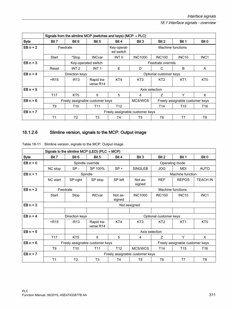
Signals from the slimline MCP (switches and keys) (MCP → PLC)Byte Bit 7 Bit 6 Bit 5 Bit 4 Bit 3 Bit 2 Bit 1 Bit 0EB n + 2 Feedrate Key-operat‐
ed switchMachine functions
Start *Stop INCvar INT 0 INC1000 INC100 INC10 INC1EB n + 3 Key-operated switch Feedrate override
Reset INT 2 INT 1 E D C B AEB n + 4 Direction keys Optional customer keys
+R15 -R13 Rapid tra‐verse R14
KT4 KT3 KT2 KT1 KT0
EB n + 5 Axis selectionT17 KT5 6 5 4 Z Y X
EB n + 6 Freely assignable customer keys MCS/WCS Freely assignable customer keysT9 T10 T11 T12 T14 T15 T16
EB n + 7 Freely assignable customer keysT1 T2 T3 T4 T5 T6 T7 T8
18.1.2.6 Slimline version, signals to the MCP: Output image
Table 18-11 Slimline version, signals to the MCP: Output image
Signals to the slimline MCP (LED) (PLC → MCP)Byte Bit 7 Bit 6 Bit 5 Bit 4 Bit 3 Bit 2 Bit 1 Bit 0EB n + 0 Spindle override Operating mode
NC stop SP - SP 100% SP + SINGLEB JOG MDI AUTOEB n + 1 Spindle Machine function
NC start SP right SP stop SP left Not as‐signed
REF REPOS TEACH IN
EB n + 2 Feedrate Machine functionsStart Stop INCvar Not as‐
signedINC1000 INC100 INC10 INC1
EB n + 3 Not assigned
EB n + 4 Direction keys Optional customer keys+R15 -R13 Rapid tra‐
verse R14KT4 KT3 KT2 KT1 KT0
EB n + 5 Axis selectionT17 KT5 6 5 4 Z Y X
EB n + 6 Freely assignable customer keys Freely assignable customer keysT9 T10 T11 T12 MCS/WCS T14 T15 T16
EB n + 7 Freely assignable customer keysT1 T2 T3 T4 T5 T6 T7 T8
Interface signals18.1 Interface signals - overview
PLCFunction Manual, 06/2019, A5E47433877B AA 311

18.1.3 Signals from/to the handheld unit HT 2
18.1.3.1 Signals from the handheld unit: Input image
Table 18-12 Signals from the handheld unit: Input image
Signals from the handheld unit (keys) (HHU / HT 2 → PLC)Byte Bit 7 Bit 6 Bit 5 Bit 4 Bit 3 Bit 2 Bit 1 Bit 0IB m + 0 Reserved Reserved Reserved Reserved Reserved Reserved Reserved ReservedIB m + 1 Reserved Reserved Reserved Reserved Reserved Reserved Reserved ReservedIB m + 2 Feedrate
startFree T2 key AUTO NC stop Spindle
stopFeed stop Free T1 key JOG
IB m + 3 Free T3 key Handwheel 4th axis Z Y X NC start Spindle start
IB m + 4 Direction key
Rapid tra‐verse over‐
ride
Direction key +
Free T4 key
IB m + 5 Acknowl‐edgementDigital dis‐
play
Key-operat‐ed switch
Rapid traverse/feedrate override switch E D C B A
18.1.3.2 Signals to the handheld unit: Output image
Table 18-13 Signals to the handheld unit: Output image
Signals to the handheld unit (LED) (PLC → HHU / HT 2)Byte Bit 7 Bit 6 Bit 5 Bit 4 Bit 3 Bit 2 Bit 1 Bit 0QB m + 0 Always 1 Free T4 key Free T3 key Free T2 key Free T1 keyQB m + 1 New data
for selected line
Selecting the line3 and 4 1 and 2
QB m + 2 Feedrate start
Rapid tra‐verse over‐
ride
AUTO NC stop Spindle stop
Feed stop Direction key +
JOG
QB m + 3 Direction key +
Handwheel 4th axis Z Y X NC start Spindle start
Digital display of the handheld unitQB m + 4 Default setting of 1st character (right) of selected line
QB m + 5 Default setting of 2nd character of selected line
QB m + 6 Default setting of 3rd character of selected line
QB m + 7 Default setting of 4th character of selected line
Interface signals18.1 Interface signals - overview
PLC312 Function Manual, 06/2019, A5E47433877B AA

Signals to the handheld unit (LED) (PLC → HHU / HT 2)Byte Bit 7 Bit 6 Bit 5 Bit 4 Bit 3 Bit 2 Bit 1 Bit 0QB m + 8 Default setting of 5th character of selected line
QB m + 9 Default setting of 6th character of selected line
QB m + 10 Default setting of 7th character of selected line QB m + 11 Default setting of 8th character of selected line
QB m + 12 Default setting of 9th character of selected line
QB m + 13 Default setting of 10th character of selected line
QB m + 14 Default setting of 11th character of selected line
QB m + 15 Default setting of 12th character of selected line
QB m + 16 Default setting of 13th character of selected line
QB m + 17 Default setting of 14th character of selected line
QB m + 18 Default setting of 15th character of selected line
QB m + 19 Default setting of 16th character (left) of selected line
Note
The parameterization or configuration of the various MCP/HHU versions is described in:Further information● Manual, Operator Components and Networking
Interface signals18.1 Interface signals - overview
PLCFunction Manual, 06/2019, A5E47433877B AA 313

18.1.4 Signals from/to the handheld unit HT 8
18.1.4.1 Signals from the handheld unit HT 8: Input image
Table 18-14 Signals from the handheld unit HT 8: Input image
Signals from the MCP simulation (HT 8 → PLC)Byte Bit 7 Bit 6 Bit 5 Bit 4 Bit 3 Bit 2 Bit 1 Bit 0EB n + 0 Function key block
REF TEACH AUTO MDI JOG QUIT Reset Work/Machine
EB n + 1 Function key blockCPF
(U key)U4 U3 BigFct U2 U1 INC REPOS
EB n + 2 Change‐over axes(HMI Ad‐
vanced on‐ly)
Traversing keys (JOG) positive direction
Ax7-Ax12 instead of Ax1-Ax6
Ax6 Ax5 Ax4 Ax3 Ax2 Ax1
EB n + 3 Traversing keys (JOG) negative direction Ax6 Ax5 Ax4 Ax3 Ax2 Ax1
EB n + 4 U9 U10 U11 U12 U13 U14 U15 U16
EB n + 5 U8 U7 U6 U5 SBL
EB n + 6 Start key blockReserved HT 8 SF2 SF1 SF4 SF3 Start Stop
EB n + 7 Feedrate override E D C B A
18.1.4.2 Signals to handheld terminal HT 8: Output image
Table 18-15 Signals from the handheld unit HT 8: Output image
Signals to the MCP simulation (PLC → HT 8)Byte Bit 7 Bit 6 Bit 5 Bit 4 Bit 3 Bit 2 Bit 1 Bit 0AB n + 0 Function key block
REF TEACH AUTO MDI JOG QUIT Reset Work/Machine
AB n + 1 Function key block U4 U3 U2 U1 INC REPOS
Interface signals18.1 Interface signals - overview
PLC314 Function Manual, 06/2019, A5E47433877B AA

Signals to the MCP simulation (PLC → HT 8)Byte Bit 7 Bit 6 Bit 5 Bit 4 Bit 3 Bit 2 Bit 1 Bit 0AB n + 2 Axes 7 - n
selectedTraversing keys (JOG) positive direction
Ax6 Ax5 Ax4 Ax3 Ax2 Ax1AB n + 3 Traversing keys (JOG) negative direction
For WCS: no machine
axes
Ax6 Ax5 Ax4 Ax3 Ax2 Ax1
AB n + 4 U9 U10 U11 U12 U13 U14 U15 U16
AB n + 5 U8 U7 U6 U5 SBL
AB n + 6 Start key blockDisplay tra‐
versing keys
SF2 SF1 SF4 SF3 Start Stop
AB n + 7
18.1.5 Signals from/to the handheld unit HT 10
18.1.5.1 Signals from the handheld unit HT 10: Input image
Table 18-16 Signals from the handheld unit HT 10: Input image
Signals from the MCP simulation (HT 10 → PLC)Byte Bit 7 Bit 6 Bit 5 Bit 4 Bit 3 Bit 2 Bit 1 Bit 0EB n + 0 Function key block
REF TEACH AUTO MDI JOG QUIT Reset Work/Machine
EB n + 1 Function key blockCPF
(U key)U4 U3 BigFct U2 U1 INC REPOS
EB n + 2 Change‐over axes(HMI Ad‐
vanced on‐ly)
Traversing keys (JOG) HT 8, positive direction
Ax7-Ax12 instead of Ax1-Ax6
Ax6 Ax5 Ax4 Ax3 Ax2 Ax1
EB n + 3 JOG keys HT 10 Traversing keys (JOG) HT 8, negative directionPlus Minus Ax6 Ax5 Ax4 Ax3 Ax2 Ax1
Interface signals18.1 Interface signals - overview
PLCFunction Manual, 06/2019, A5E47433877B AA 315

Signals from the MCP simulation (HT 10 → PLC)Byte Bit 7 Bit 6 Bit 5 Bit 4 Bit 3 Bit 2 Bit 1 Bit 0EB n + 4
U16 U15 U14 U13 U12 U11 U10 U9EB n + 5
U8 U7 U6 U5 SBL Rapid tra‐verse
EB n + 6 Start key blockHT 10 HT 8 SF2 SF1 SF4 SF3 Start Stop
EB n + 7 Feedrate override E D C B A
18.1.5.2 Signals to handheld terminal HT 10: Output image
Table 18-17 Signals from the handheld unit HT 10: Output image
Signals to the MCP simulation (PLC → HT 10)Byte Bit 7 Bit 6 Bit 5 Bit 4 Bit 3 Bit 2 Bit 1 Bit 0AB n + 0 Function key block
REF TEACH AUTO MDI JOG QUIT Reset Work/Machine
AB n + 1 Function key block U4 U3 U2 U1 INC REPOS
AB n + 2 JOG +(HT 10)
Axes 7 - n selected
Traversing keys (JOG) HT 8, positive direction
Ax6 Ax5 Ax4 Ax3 Ax2 Ax1AB n + 3 Traversing keys (JOG) HT 8, negative direction
For WCS: no machine
axes
JOG -(HT 10)
Ax6 Ax5 Ax4 Ax3 Ax2 Ax1
AB n + 4 U9 U10 U11 U12 U13 U14 U15 U16
AB n + 5 U8 U7 U6 U5 SBL Rapid tra‐
verseAB n + 6 Start key block
Display tra‐versing
keys
SF2 SF1 SF4 SF3 Start Stop
AB n + 7
Interface signals18.1 Interface signals - overview
PLC316 Function Manual, 06/2019, A5E47433877B AA

18.1.6 PLC alarms/messages
18.1.6.1 FC 10 alarms in the DB2 (FB1: "ExtendAIMsg" = FALSE)
Message type● FM: A fault message with the associated event number as fault number is triggered by the
signal.
● OM: An operating message with the associated event number as message number is triggered by the signal.
Further informationA detailed description regarding error and system status messages can be obtained in:FC10: AL_MSG - error and operating messages (Page 247)
Table 18-18 DB2, channel range 1
DB2 Signals for PLC events (PLC → HMI) FB1 parameter "ExtendAIMsg" = FALSE
Byte(message
type)
Bit 7 Bit 6 Bit 5 Bit 4 Bit 3 Bit 2 Bit 1 Bit 0
Channel 1 Feedrate disable (event no.: 510000-510015)0 (FM) 510007 510006 510005 510004 510003 510002 510001 5100001 (OM) 510015 510014 510013 510012 510011 510010 510009 5100082 (FM) Feedrate and read-in disable, byte 1 (event no.: 510100-510107)3 (FM) Feedrate and read-in disable, byte 2 (event no.: 510108-510115)4 (OM) Feedrate and read-in disable, byte 3 (event no.: 510116-510123)5 (OM) Feedrate and read-in disable, byte 4 (event no.: 510124-510131)6 (FM) Read-in disable, byte 1 (event no.: 510200-510207)7 (FM) Read-in disable, byte 2 (event no.: 510208-510215)8 (OM) Read-in disable, byte 3 (event no.: 510216-510223)9 (OM) Read-in disable, byte 4 (event no.: 510224-510231)10 (FM) NC start disable, byte 1 (event no.: 510300-510307)11 (OM) NC start disable, byte 2 (event no.: 510308-510315)12 (FM) Feedrate stop, geo axis 1, byte 1 (event no.: 511100-511107)13 (OM) Feedrate stop, geo axis 1, byte 2 (event no.: 511108-511115)14 (FM) Feedrate stop, geo axis 2, byte 1 (event no.: 511200-511207)15 (OM) Feedrate stop, geo axis 2, byte 2 (event no.: 511208-511215)16 (FM) Feedrate stop, geo axis 3, byte 1 (event no.: 511300-511307)17 (OM) Feedrate stop, geo axis 3, byte 2 (event no.: 511308-511315)
Interface signals18.1 Interface signals - overview
PLCFunction Manual, 06/2019, A5E47433877B AA 317

Table 18-19 DB2, channel range 2
DB2 Signals for PLC events (PLC → HMI) FB1 parameter "ExtendAIMsg" = FALSE
Byte(message
type)
Bit 7 Bit 6 Bit 5 Bit 4 Bit 3 Bit 2 Bit 1 Bit 0
Channel 2 Feedrate disable (event no.: 520000-520015)18 (FM) 520007 520006 520005 520004 520003 520002 520001 52000019 (OM) 520015 520014 520013 520012 520011 520010 520009 52000820 (FM) Feedrate and read-in disable, byte 1 (event no.: 520100-520107)21 (FM) Feedrate and read-in disable, byte 2 (event no.: 520108-520115)22 (OM) Feedrate and read-in disable, byte 3 (event no.: 520116-520123)23 (OM) Feedrate and read-in disable, byte 4 (event no.: 520124-520131)24 (FM) Read-in disable, byte 1 (event no.: 520200-520207)25 (FM) Read-in disable, byte 2 (event no.: 520208-520215)26 (OM) Read-in disable, byte 3 (event no.: 520216-520223)27 (OM) Read-in disable, byte 4 (event no.: 520224-520231)28 (FM) NC start disable, byte 1 (event no.: 520300-520307)29 (OM) NC start disable, byte 2 (event no.: 520308-520315)30 (FM) Feedrate stop, geo axis 1, byte 1 (event no.: 521100-521107)31 (OM) Feedrate stop, geo axis 1, byte 2 (event no.: 521108-521115)32 (FM) Feedrate stop, geo axis 2, byte 1 (event no.: 521200-521207)33 (OM) Feedrate stop, geo axis 2, byte 2 (event no.: 521208-521215)34 (FM) Feedrate stop, geo axis 3, byte 1 (event no.: 521300-521307)35 (OM) Feedrate stop, geo axis 3, byte 2 (event no.: 521308-521315)
Table 18-20 DB2, channel range 3
DB2 Signals for PLC events (PLC → HMI) FB1 parameter "ExtendAIMsg" = FALSE
Byte(message
type)
Bit 7 Bit 6 Bit 5 Bit 4 Bit 3 Bit 2 Bit 1 Bit 0
Channel 3 Feedrate disable (event no.: 530000-530015)36 (FM) 530007 530006 530005 530004 530003 530002 530001 53000037 (OM) 530015 530014 530013 530012 530011 530010 530009 53000838 (FM) Feedrate and read-in disable, byte 1 (event no.: 530100-530107)39 (FM) Feedrate and read-in disable, byte 2 (event no.: 530108-530115)40 (OM) Feedrate and read-in disable, byte 3 (event no.: 530116-530123)41 (OM) Feedrate and read-in disable, byte 4 (event no.: 530124-530131)42 (FM) Read-in disable, byte 1 (event no.: 530200-530207)43 (FM) Read-in disable, byte 2 (event no.: 530208-530215)
Interface signals18.1 Interface signals - overview
PLC318 Function Manual, 06/2019, A5E47433877B AA

DB2 Signals for PLC events (PLC → HMI) FB1 parameter "ExtendAIMsg" = FALSE
Byte(message
type)
Bit 7 Bit 6 Bit 5 Bit 4 Bit 3 Bit 2 Bit 1 Bit 0
44 (OM) Read-in disable, byte 3 (event no.: 530216-530223)45 (OM) Read-in disable, byte 4 (event no.: 530224-530231)46 (FM) NC start disable, byte 1 (event no.: 530300-530307)47 (OM) NC start disable, byte 2 (event no.: 530308-530315)48 (FM) Feedrate stop, geo axis 1, byte 1 (event no.: 531100-531107)49 (OM) Feedrate stop, geo axis 1, byte 2 (event no.: 531108-531115)50 (FM) Feedrate stop, geo axis 2, byte 1 (event no.: 531200-531207)51 (OM) Feedrate stop, geo axis 2, byte 2 (event no.: 531208-531215)52 (FM) Feedrate stop, geo axis 3, byte 1 (event no.: 531300-531307)53 (OM) Feedrate stop, geo axis 3, byte 2 (event no.: 531308-531315)
Table 18-21 DB2, channel range 4
DB2 Signals for PLC events (PLC → HMI) FB1 parameter "ExtendAIMsg" = FALSE
Byte(message
type)
Bit 7 Bit 6 Bit 5 Bit 4 Bit 3 Bit 2 Bit 1 Bit 0
Channel 4 Feedrate disable (event no.: 540000-540015)54 (FM) 540007 540006 540005 540004 540003 540002 540001 54000055 (OM) 540015 540014 540013 540012 540011 540010 540009 54000856 (FM) Feedrate and read-in disable, byte 1 (event no.: 540100-540107)57 (FM) Feedrate and read-in disable, byte 2 (event no.: 540108-540115)58 (OM) Feedrate and read-in disable, byte 3 (event no.: 540116-540123)59 (OM) Feedrate and read-in disable, byte 4 (event no.: 540124-540131)60 (FM) Read-in disable, byte 1 (event no.: 540200-540207)61 (FM) Read-in disable, byte 2 (event no.: 540208-540215)62 (OM) Read-in disable, byte 3 (event no.: 540216-540223)63 (OM) Read-in disable, byte 4 (event no.: 540224-540231)64 (FM) NC start disable, byte 1 (event no.: 540300-540307)65 (FM) NC start disable, byte 2 (event no.: 540308-540315)66 (FM) Feedrate stop, geo axis 1, byte 1 (event no.: 541100-541107)67 (OM) Feedrate stop, geo axis 1, byte 2 (event no.: 541108-541115)68 (FM) Feedrate stop, geo axis 2, byte 1 (event no.: 541200-541207)69 (OM) Feedrate stop, geo axis 2, byte 2 (event no.: 541208-541215)70 (FM) Feedrate stop, geo axis 3, byte 1 (event no.: 541300-541307)71 (OM) Feedrate stop, geo axis 3, byte 2 (event no.: 541308-541315)
Interface signals18.1 Interface signals - overview
PLCFunction Manual, 06/2019, A5E47433877B AA 319

Table 18-22 DB2, channel range 5
DB2 Signals for PLC events (PLC → HMI) FB1 parameter "ExtendAIMsg" = FALSE
Byte(message
type)
Bit 7 Bit 6 Bit 5 Bit 4 Bit 3 Bit 2 Bit 1 Bit 0
Channel 5 Feedrate disable (event no.: 550000-550015)72 (FM) 550007 550006 550005 550004 550003 550002 550001 55000073 (OM) 550015 550014 550013 550012 550011 550010 550009 55000874 (FM) Feedrate and read-in disable, byte 1 (event no.: 550100-550107)75 (OM) Feedrate and read-in disable, byte 2 (event no.: 550108-550115)76 (OM) Feedrate and read-in disable, byte 3 (event no.: 550116-550123)77 (OM) Feedrate and read-in disable, byte 4 (event no.: 550124-550131)78 (FM) Read-in disable, byte 1 (event no.: 550200-550207)79 (FM) Read-in disable, byte 2 (event no.: 550208-550315)80 (OM) Read-in disable, byte 3 (event no.: 550216-550223)81 (OM) Read-in disable, byte 4 (event no.: 550224-550231)82 (FM) NC start disable, byte 1 (event no.: 550300-550307)83 (OM) NC start disable, byte 2 (event no.: 550308-550315)84 (FM) Feedrate stop, geo axis 1, byte 1 (event no.: 551100-551107)85 (OM) Feedrate stop, geo axis 1, byte 2 (event no.: 551108-551115)86 (FM) Feedrate stop, geo axis 2, byte 1 (event no.: 551200-551207)87 (OM) Feedrate stop, geo axis 2, byte 2 (event no.: 551208-551215)88 (FM) Feedrate stop, geo axis 3, byte 1 (event no.: 551300-551307)89 (OM) Feedrate stop, geo axis 3, byte 2 (event no.: 551308-551315)
Table 18-23 DB2, channel range 6
DB2 Signals for PLC events (PLC → HMI) FB1 parameter "ExtendAIMsg" = FALSE
Byte(message
type)
Bit 7 Bit 6 Bit 5 Bit 4 Bit 3 Bit 2 Bit 1 Bit 0
Channel 6 Feedrate disable (event no.: 560000-560015)90 (FM) 560007 560006 560005 560004 560003 560002 560001 56000091 (OM) 560015 560014 560013 560012 560011 560010 560009 56000892 (FM) Feedrate and read-in disable, byte 1 (event no.: 560100-560107)93 (FM) Feedrate and read-in disable, byte 2 (event no.: 560108-560115)94 (OM) Feedrate and read-in disable, byte 3 (event no.: 560116-560123)95 (OM) Feedrate and read-in disable, byte 4 (event no.: 560124-560131)96 (FM) Read-in disable, byte 1 (event no.: 560200-560207)97 (FM) Read-in disable, byte 2 (event no.: 560208-560315)
Interface signals18.1 Interface signals - overview
PLC320 Function Manual, 06/2019, A5E47433877B AA

DB2 Signals for PLC events (PLC → HMI) FB1 parameter "ExtendAIMsg" = FALSE
Byte(message
type)
Bit 7 Bit 6 Bit 5 Bit 4 Bit 3 Bit 2 Bit 1 Bit 0
98 (OM) Read-in disable, byte 3 (event no.: 560216-560223)99 (OM) Read-in disable, byte 4 (event no.: 560224-560231)100 (FM) NC start disable, byte 1 (event no.: 560300-560307)101 (OM) NC start disable, byte 2 (event no.: 560308-560315)102 (FM) Feedrate stop, geo axis 1, byte 1 (event no.: 561100-561107)103 (OM) Feedrate stop, geo axis 1, byte 2 (event no.: 561108-561115)104 (FM) Feedrate stop, geo axis 2, byte 1 (event no.: 561200-561207)105 (OM) Feedrate stop, geo axis 2, byte 2 (event no.: 561208-561215)106 (FM) Feedrate stop, geo axis 3, byte 1 (event no.: 561300-561307)107 (OM) Feedrate stop, geo axis 3, byte 2 (event no.: 561308-561315)
Table 18-24 DB2, channel range 7
DB2 Signals for PLC events (PLC → HMI) FB1 parameter "ExtendAIMsg" = FALSE
Byte(message
type)
Bit 7 Bit 6 Bit 5 Bit 4 Bit 3 Bit 2 Bit 1 Bit 0
Channel 7 Feedrate disable (event no.: 570000-570015)108 (FM) 570007 570006 570005 570004 570003 570002 570001 570000109 (OM) 570015 570014 570013 570012 570011 570010 570009 570008110 (FM) Feedrate and read-in disable, byte 1 (event no.: 570100-570107)111 (FM) Feedrate and read-in disable, byte 2 (event no.: 570108-570115)112 (OM) Feedrate and read-in disable, byte 3 (event no.: 570116-570123)113 (OM) Feedrate and read-in disable, byte 4 (event no.: 570124-570131)114 (FM) Read-in disable, byte 1 (event no.: 570200-570207)115 (FM) Read-in disable, byte 2 (event no.: 570208-570315)116 (OM) Read-in disable, byte 3 (event no.: 570216-570223)117 (OM) Read-in disable, byte 4 (event no.: 570224-570231)118 (FM) NC start disable, byte 1 (event no.: 570300-570307)119 (OM) NC start disable, byte 2 (event no.: 570308-570315)120 (FM) Feedrate stop, geo axis 1, byte 1 (event no.: 571100-571107)121 (OM) Feedrate stop, geo axis 1, byte 2 (event no.: 571108-571115)122 (FM) Feedrate stop, geo axis 2, byte 1 (event no.: 571200-571207)123 (OM) Feedrate stop, geo axis 2, byte 2 (event no.: 571208-571215)124 (FM) Feedrate stop, geo axis 3, byte 1 (event no.: 571300-571307)125 (OM) Feedrate stop, geo axis 3, byte 2 (event no.: 571308-571315)
Interface signals18.1 Interface signals - overview
PLCFunction Manual, 06/2019, A5E47433877B AA 321

Table 18-25 DB2, channel range 8
DB2 Signals for PLC events (PLC → HMI) FB1 parameter "ExtendAIMsg" = FALSE
Byte(message
type)
Bit 7 Bit 6 Bit 5 Bit 4 Bit 3 Bit 2 Bit 1 Bit 0
Channel 8 Feedrate disable (event no.: 580000-580015)126 (FM) 580007 580006 580005 580004 580003 580002 580001 580000127 (OM) 580015 580014 580013 580012 580011 580010 580009 580008128 (FM) Feedrate and read-in disable, byte 1 (event no.: 580100-580107)129 (FM) Feedrate and read-in disable, byte 2 (event no.: 580108-580115)130 (OM) Feedrate and read-in disable, byte 3 (event no.: 580116-580123)131 (OM) Feedrate and read-in disable, byte 4 (event no.: 580124-580131)132 (FM) Read-in disable, byte 1 (event no.: 580200-580207)133 (FM) Read-in disable, byte 2 (event no.: 580208-580315)134 (OM) Read-in disable, byte 3 (event no.: 580216-580223)135 (OM) Read-in disable, byte 4 (event no.: 580224-580231)136 (FM) NC start disable, byte 1 (event no.: 580300-580307)137 (OM) NC start disable, byte 2 (event no.: 580308-580315)138 (FM) Feedrate stop, geo axis 1, byte 1 (event no.: 581100-581107)139 (OM) Feedrate stop, geo axis 1, byte 2 (event no.: 581108-581115)140 (FM) Feedrate stop, geo axis 2, byte 1 (event no.: 581200-581207)141 (OM) Feedrate stop, geo axis 2, byte 2 (event no.: 581208-581215)142 (FM) Feedrate stop, geo axis 3, byte 1 (event no.: 581300-581307)143 (OM) Feedrate stop, geo axis 3, byte 2 (event no.: 581308-581315) Channels 9 and 10 not implemented
Table 18-26 DB2, axis ranges
DB2 Signals for PLC events (PLC → HMI) FB1 parameter "ExtendAIMsg" = FALSE
Byte(message
type)
Bit 7 Bit 6 Bit 5 Bit 4 Bit 3 Bit 2 Bit 1 Bit 0
Axis/spindle Feedrate stop / spindle stop for axis/spindle 1 (event no.: 600100-600115)144 (FM) 600107 600106 600105 600104 600103 600102 600101 600100145 (OM) 600115 600114 600113 600112 600111 600110 600109 600108146 (FM) Feedrate stop / spindle stop for axis/spindle 2, byte 1 (event no.: 600200-600207)147 (OM) Feedrate stop / spindle stop for axis/spindle 2, byte 2 (event no.: 600208-600215)148 (FM) Feedrate stop / spindle stop for axis/spindle 3, byte 1 (event no.: 600300-600307)149 (OM) Feedrate stop / spindle stop for axis/spindle 3, byte 2 (event no.: 600308-600315)150 (FM) Feedrate stop / spindle stop for axis/spindle 4, byte 1 (event no.: 600400-600407)
Interface signals18.1 Interface signals - overview
PLC322 Function Manual, 06/2019, A5E47433877B AA

DB2 Signals for PLC events (PLC → HMI) FB1 parameter "ExtendAIMsg" = FALSE
Byte(message
type)
Bit 7 Bit 6 Bit 5 Bit 4 Bit 3 Bit 2 Bit 1 Bit 0
151 (OM) Feedrate stop / spindle stop for axis/spindle 4, byte 2 (event no.: 600408-600415)152 (FM) Feedrate stop / spindle stop for axis/spindle 5, byte 1 (event no.: 600500-600507)153 (OM) Feedrate stop / spindle stop for axis/spindle 5, byte 2 (event no.: 600508-600515)154 (FM) Feedrate stop / spindle stop for axis/spindle 6, byte 1 (event no.: 600600-600607)155 (OM) Feedrate stop / spindle stop for axis/spindle 6, byte 2 (event no.: 600608-600615)156 (FM) Feedrate stop / spindle stop for axis/spindle 7, byte 1 (event no.: 600700-600707)157 (OM) Feedrate stop / spindle stop for axis/spindle 7, byte 2 (event no.: 600708-600715)158 (FM) Feedrate stop / spindle stop for axis/spindle 8, byte 1 (event no.: 600800-600807)159 (OM) Feedrate stop / spindle stop for axis/spindle 8, byte 2 (event no.: 600808-600815)160 (FM) Feedrate stop / spindle stop for axis/spindle 9, byte 1 (event no.: 600900-600907)161 (OM) Feedrate stop / spindle stop for axis/spindle 9, byte 2 (event no.: 600908-600915)162 (FM) Feedrate stop/spindle stop for axis/spindle 10 byte 1 (event no.: 601000-601007)163 (OM) Feedrate stop/spindle stop for axis/spindle 10 byte 2 (event no.: 601008-601015)164 (FM) Feedrate stop/spindle stop for axis/spindle 11 byte 1 (event no.: 601100-601107)165 (OM) Feedrate stop/spindle stop for axis/spindle 11 byte 2 (event no.: 601108-601115)166 (FM) Feedrate stop/spindle stop for axis/spindle 12 byte 1 (event no.: 601200-601207)167 (OM) Feedrate stop/spindle stop for axis/spindle 12 byte 2 (event no.: 601208-601215)168 (FM) Feedrate stop/spindle stop for axis/spindle 13 byte 1 (event no.: 601300-601307)169 (OM) Feedrate stop/spindle stop for axis/spindle 13 byte 2 (event no.: 601308-601315)170 (FM) Feedrate stop/spindle stop for axis/spindle 14 byte 1 (event no.: 601400-601407)171 (OM) Feedrate stop/spindle stop for axis/spindle 14 byte 2 (event no.: 601408-601415)172 (FM) Feedrate stop/spindle stop for axis/spindle 15 byte 1 (event no.: 601500-601507)173 (OM) Feedrate stop/spindle stop for axis/spindle 15 byte 2 (event no.: 601508-601515)174 (FM) Feedrate stop/spindle stop for axis/spindle 16 byte 1 (event no.: 601600-601607)175 (OM) Feedrate stop/spindle stop for axis/spindle 16 byte 2 (event no.: 601608-601615)176 (FM) Feedrate stop/spindle stop for axis/spindle 17 byte 1 (event no.: 601700-601707)177 (OM) Feedrate stop/spindle stop for axis/spindle 17 byte 2 (event no.: 601708-601715)178 (FM) Feedrate stop/spindle stop for axis/spindle 18 byte 1 (event no.: 601800-601807)179 (OM) Feedrate stop/spindle stop for axis/spindle 18 byte 2 (event no.: 601808-601815) Axes 19 – 31 not realized
Table 18-27 DB2, user ranges
DB2 Signals for PLC events (PLC → HMI) FB1 parameter "ExtendAIMsg" = FALSE
Byte(message type)
Bit 7 Bit 6 Bit 5 Bit 4 Bit 3 Bit 2 Bit 1 Bit 0
User ranges User range 0 (event no.: 700000-700015)
Interface signals18.1 Interface signals - overview
PLCFunction Manual, 06/2019, A5E47433877B AA 323

DB2 Signals for PLC events (PLC → HMI) FB1 parameter "ExtendAIMsg" = FALSE
Byte(message type)
Bit 7 Bit 6 Bit 5 Bit 4 Bit 3 Bit 2 Bit 1 Bit 0
180 (FM) 700007 700006 700005 700004 700003 700002 700001 700000181 (FM) 700015 700014 700013 700012 700011 700010 700009 700008182 (FM) User range 0: Byte 3 (event no.: 700016-700023)183 (FM) User range 0: Byte 4 (event no.: 700024-700031)184 (OM) User range 0: Byte 5 (event no.: 700032-700039)185 (OM) User range 0: Byte 6 (event no.: 700040-700047)186 (OM) User range 0: Byte 7 (event no.: 700048-700055)187 (OM) User range 0: Byte 8 (event no.: 700056-700063)188 - 191 (FM) User range 1: Byte 1 - 4 (event no.: 700100-700131)192 - 195 (OM) User range 1, bytes 5 - 8 (event no.: 700132-700163)196 - 199 (FM) User range 2: Byte 1 - 4 (event no.: 700200-700231)200 - 203 (OM) User range 2: Byte 5 - 8 (event no.: 700232-700263)204 - 207 (FM) User range 3: Byte 1 - 4 (event no.: 700300-700331)208 - 211 (OM) User range 3: Byte 5 - 8 (event no.: 700332-700363)212 - 215 (FM) User range 4: Byte 1 - 4 (event no.: 700400-700431)216 - 219 (OM) User range 4: Byte 5 - 8 (event no.: 700432-700463)220 - 223 (FM) User range 5: Byte 1 - 4 (event no.: 700500-700531)224 - 227 (OM) User range 5: Byte 5 - 8 (event no.: 700532-700563)228 - 231 (FM) User range 6: Byte 1 - 4 (event no.: 700600-700631)232 - 235 (OM) User range 6: Byte 5 - 8 (event no.: 700632-700663)236 - 239 (FM) User range 7: Byte 1 - 4 (event no.: 700700-700731)240 - 243 (OM) User range 7: Byte 5 - 8 (event no.: 700732-700763)244 - 247 (FM) User range 8: Byte 1 - 4 (event no.: 700800-700831)248 - 251 (OM) User range 8: Byte 5 - 8 (event no.: 700832-700863)252 - 255 (FM) User range 9: Byte 1 - 4 (event no.: 700900-700931)256 - 259 (OM) User range 9: Byte 5 - 8 (event no.: 700932-700963)260 - 263 (FM) User range 10: Byte 1 - 4 (event no.: 701000-701031)264 - 267 (OM) User range 10: Byte 5 - 8 (event no.: 701032-701063)268 - 271 (FM) User range 11: Byte 1 - 4 (event no.: 701100-701131)272 - 275 (OM) User range 11: Byte 5 - 8 (event no.: 701132-701163)276 - 279 (FM) User range 12: Byte 1 - 4 (event no.: 701200-701231)280 - 283 (OM) User range 12: Byte 5 - 8 (event no.: 701232-701263)284 - 287 (FM) User range 13: Byte 1 - 4 (event no.: 701300-701331)288 - 291 (OM) User range 13: Byte 5 - 8 (event no.: 701332-701363)292 - 295 (FM) User range 14: Byte 1 - 4 (event no.: 701400-701431)296 - 299 (OM) User range 14: Byte 5 - 8 (event no.: 701432-701463)300 - 303 (FM) User range 15: Byte 1 - 4 (event no.: 701500-701531)304 - 307 (OM) User range 15: Byte 5 - 8 (event no.: 701532-701563)308 - 311 (FM) User range 16: Byte 1 - 4 (event no.: 701600-701631)312 - 315 (OM) User range 16: Byte 5 - 8 (event no.: 701632-701663)
Interface signals18.1 Interface signals - overview
PLC324 Function Manual, 06/2019, A5E47433877B AA

DB2 Signals for PLC events (PLC → HMI) FB1 parameter "ExtendAIMsg" = FALSE
Byte(message type)
Bit 7 Bit 6 Bit 5 Bit 4 Bit 3 Bit 2 Bit 1 Bit 0
316 - 319 (FM) User range 17: Byte 1 - 4 (event no.: 701700-701731)320 - 323 (OM) User range 17: Byte 5 - 8 (event no.: 701732-701763)324 - 327 (FM) User range 18: Byte 1 - 4 (event no.: 701800-701831)328 - 331 (OM) User range 18: Byte 5 - 8 (event no.: 701832-701863)332 - 335 (FM) User range 19: Byte 1 - 4 (event no.: 701900-701931)336 - 339 (OM) User range 19: Byte 5 - 8 (event no.: 701932-701963)340 - 343 (FM) User range 20: Byte 1 - 4 (event no.: 702000-702031)344 - 347 (OM) User range 20: Byte 5 - 8 (event no.: 702032-702063)348 - 351 (FM) User range 21: Byte 1 - 4 (event no.: 702100-702131)352 - 355 (OM) User range 21: Byte 5 - 8 (event no.: 702132-702163)356 - 359 (FM) User range 22: Byte 1 - 4 (event no.: 702200-702231)360 - 363 (OM) User range 22: Byte 5 - 8 (event no.: 702232-702263)364 - 367 (FM) User range 23: Byte 1 - 4 (event no.: 702300-702331)368 - 371 (OM) User range 23: Byte 5 - 8 (event no.: 702332-702363)372 - 375 (FM) User range 24: Byte 1 - 4 (event no.: 702400-702431)376 - 379 (OM) User range 24: Byte 5 - 8 (event no.: 702432-702463)380 - 383 (FM) User range 25: Byte 1 - 4 (event no.: 702500-702531)384 - 387 (OM) User range 25: Byte 5 - 8 (event no.: 702532-702563)388 - 391 (FM) User range 26: Byte 1 - 4 (event no.: 702600-702631)392 - 395 (OM) User range 26: Byte 5 - 8 (event no.: 702632-702663)396 - 399 (FM) User range 27: Byte 1 - 4 (event no.: 702700-702731)400 - 403 (OM) User range 27: Byte 5 - 8 (event no.: 702732-702763)404 - 407 (FM) User range 28: Byte 1 - 4 (event no.: 702800-702831)408 - 411 (OM) User range 28: Byte 5 - 8 (event no.: 702832-702863)412 - 415 (FM) User range 29: Byte 1 - 4 (event no.: 702900-702931)416 - 419 (OM) User range 29: Byte 5 - 8 (event no.: 702932-702963)420 - 423 (FM) User range 30: Byte 1 - 4 (event no.: 703000-703031)424 - 427 (OM) User range 30: Byte 5 - 8 (event no.: 703032-703063)428 - 431 (FM) User range 31: Byte 1 - 4 (event no.: 703100-703131)432 - 435 (OM) User range 31: Byte 5 - 8 (event no.: 703132-703163)
NoteParameterizing user ranges
The number of user ranges (maximum of 32) can be parameterized using FB 1 "MsgUser".
Interface signals18.1 Interface signals - overview
PLCFunction Manual, 06/2019, A5E47433877B AA 325
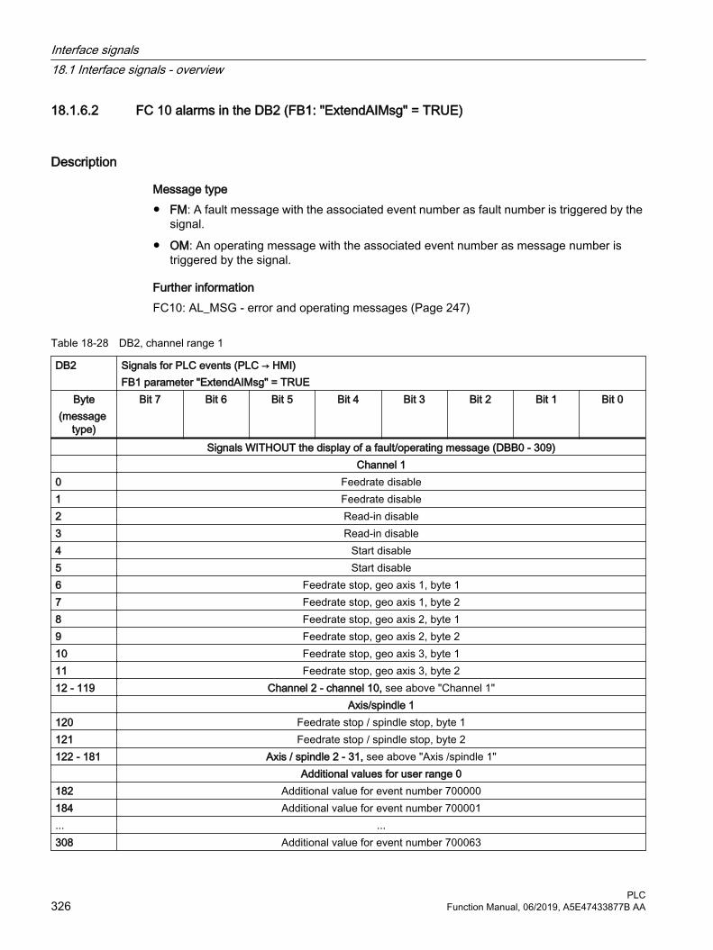
18.1.6.2 FC 10 alarms in the DB2 (FB1: "ExtendAIMsg" = TRUE)
Description
Message type● FM: A fault message with the associated event number as fault number is triggered by the
signal.
● OM: An operating message with the associated event number as message number is triggered by the signal.
Further informationFC10: AL_MSG - error and operating messages (Page 247)
Table 18-28 DB2, channel range 1
DB2 Signals for PLC events (PLC → HMI) FB1 parameter "ExtendAIMsg" = TRUE
Byte(message
type)
Bit 7 Bit 6 Bit 5 Bit 4 Bit 3 Bit 2 Bit 1 Bit 0
Signals WITHOUT the display of a fault/operating message (DBB0 - 309) Channel 10 Feedrate disable1 Feedrate disable2 Read-in disable3 Read-in disable4 Start disable5 Start disable6 Feedrate stop, geo axis 1, byte 17 Feedrate stop, geo axis 1, byte 28 Feedrate stop, geo axis 2, byte 19 Feedrate stop, geo axis 2, byte 210 Feedrate stop, geo axis 3, byte 111 Feedrate stop, geo axis 3, byte 212 - 119 Channel 2 - channel 10, see above "Channel 1" Axis/spindle 1120 Feedrate stop / spindle stop, byte 1121 Feedrate stop / spindle stop, byte 2122 - 181 Axis / spindle 2 - 31, see above "Axis /spindle 1" Additional values for user range 0182 Additional value for event number 700000184 Additional value for event number 700001... ...308 Additional value for event number 700063
Interface signals18.1 Interface signals - overview
PLC326 Function Manual, 06/2019, A5E47433877B AA
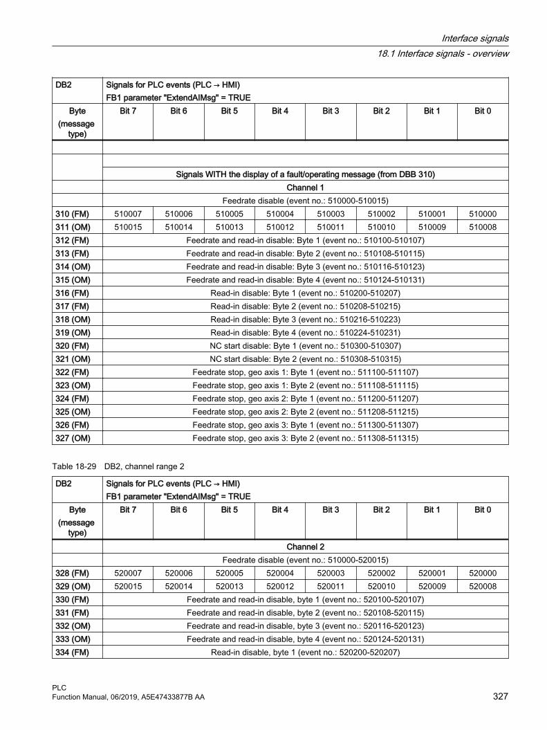
DB2 Signals for PLC events (PLC → HMI) FB1 parameter "ExtendAIMsg" = TRUE
Byte(message
type)
Bit 7 Bit 6 Bit 5 Bit 4 Bit 3 Bit 2 Bit 1 Bit 0
Signals WITH the display of a fault/operating message (from DBB 310) Channel 1 Feedrate disable (event no.: 510000-510015)310 (FM) 510007 510006 510005 510004 510003 510002 510001 510000311 (OM) 510015 510014 510013 510012 510011 510010 510009 510008312 (FM) Feedrate and read-in disable: Byte 1 (event no.: 510100-510107)313 (FM) Feedrate and read-in disable: Byte 2 (event no.: 510108-510115)314 (OM) Feedrate and read-in disable: Byte 3 (event no.: 510116-510123)315 (OM) Feedrate and read-in disable: Byte 4 (event no.: 510124-510131)316 (FM) Read-in disable: Byte 1 (event no.: 510200-510207)317 (FM) Read-in disable: Byte 2 (event no.: 510208-510215)318 (OM) Read-in disable: Byte 3 (event no.: 510216-510223)319 (OM) Read-in disable: Byte 4 (event no.: 510224-510231)320 (FM) NC start disable: Byte 1 (event no.: 510300-510307)321 (OM) NC start disable: Byte 2 (event no.: 510308-510315)322 (FM) Feedrate stop, geo axis 1: Byte 1 (event no.: 511100-511107)323 (OM) Feedrate stop, geo axis 1: Byte 2 (event no.: 511108-511115)324 (FM) Feedrate stop, geo axis 2: Byte 1 (event no.: 511200-511207)325 (OM) Feedrate stop, geo axis 2: Byte 2 (event no.: 511208-511215)326 (FM) Feedrate stop, geo axis 3: Byte 1 (event no.: 511300-511307)327 (OM) Feedrate stop, geo axis 3: Byte 2 (event no.: 511308-511315)
Table 18-29 DB2, channel range 2
DB2 Signals for PLC events (PLC → HMI) FB1 parameter "ExtendAIMsg" = TRUE
Byte(message
type)
Bit 7 Bit 6 Bit 5 Bit 4 Bit 3 Bit 2 Bit 1 Bit 0
Channel 2 Feedrate disable (event no.: 510000-520015)328 (FM) 520007 520006 520005 520004 520003 520002 520001 520000329 (OM) 520015 520014 520013 520012 520011 520010 520009 520008330 (FM) Feedrate and read-in disable, byte 1 (event no.: 520100-520107)331 (FM) Feedrate and read-in disable, byte 2 (event no.: 520108-520115)332 (OM) Feedrate and read-in disable, byte 3 (event no.: 520116-520123)333 (OM) Feedrate and read-in disable, byte 4 (event no.: 520124-520131)334 (FM) Read-in disable, byte 1 (event no.: 520200-520207)
Interface signals18.1 Interface signals - overview
PLCFunction Manual, 06/2019, A5E47433877B AA 327

DB2 Signals for PLC events (PLC → HMI) FB1 parameter "ExtendAIMsg" = TRUE
Byte(message
type)
Bit 7 Bit 6 Bit 5 Bit 4 Bit 3 Bit 2 Bit 1 Bit 0
335 (FM) Read-in disable, byte 2 (event no.: 520208-520215)336 (OM) Read-in disable, byte 3 (event no.: 520216-520223)337 (OM) Read-in disable, byte 4 (event no.: 520224-520231)338 (FM) NC start disable, byte 1 (event no.: 520300-520307)339 (OM) NC start disable, byte 2 (event no.: 520308-520315)340 (FM) Feedrate stop, geo axis 1, byte 1 (event no.: 521100-521107)341 (OM) Feedrate stop, geo axis 1, byte 2 (event no.: 521108-521115)342 (FM) Feedrate stop, geo axis 2, byte 1 (event no.: 521200-521207)343 (OM) Feedrate stop, geo axis 2, byte 2 (event no.: 521208-521215)344 (FM) Feedrate stop, geo axis 3, byte 1 (event no.: 521300-521307)345 (OM) Feedrate stop, geo axis 3, byte 2 (event no.: 521308-521315)
Table 18-30 DB2, channel range 3
DB2 Signals for PLC events (PLC → HMI) FB1 parameter "ExtendAIMsg" = TRUE
Byte(message
type)
Bit 7 Bit 6 Bit 5 Bit 4 Bit 3 Bit 2 Bit 1 Bit 0
Channel 3 Feedrate disable (event no.: 530000-530015)346 (FM) 530007 530006 530005 530004 530003 530002 530001 530000347 (OM) 530015 530014 530013 530012 530011 530010 530009 530008348 (FM) Feedrate and read-in disable, byte 1 (event no.: 530100-530107)349 (FM) Feedrate and read-in disable, byte 2 (event no.: 530108-530115)350 (OM) Feedrate and read-in disable, byte 2 (event no.: 530108-530115)351 (OM) Feedrate and read-in disable, byte 4 (event no.: 530124-530131)352 (FM) Read-in disable, byte 1 (event no.: 530200-530207)353 (FM) Read-in disable, byte 2 (event no.: 530208-530215)354 (OM) Read-in disable, byte 3 (event no.: 530216-530223)355 (OM) Read-in disable, byte 4 (event no.: 530224-530231)356 (FM) NC start disable, byte 1 (event no.: 530300-530307)357 (OM) NC start disable, byte 2 (event no.: 530308-530315)358 (FM) Feedrate stop, geo axis 1, byte 1 (event no.: 531100-531107)359 (OM) Feedrate stop, geo axis 1, byte 2 (event no.: 531108-531115)360 (FM) Feedrate stop, geo axis 2, byte 1 (event no.: 531200-531207)361 (OM) Feedrate stop, geo axis 2, byte 2 (event no.: 531208-531215)362 (FM) Feedrate stop, geo axis 3, byte 1 (event no.: 531300-531307)363 (OM) Feedrate stop, geo axis 3, byte 2 (event no.: 531308-531315)
Interface signals18.1 Interface signals - overview
PLC328 Function Manual, 06/2019, A5E47433877B AA

Table 18-31 DB2, channel range 4
DB2 Signals for PLC events (PLC → HMI) FB1 parameter "ExtendAIMsg" = TRUE
Byte(message
type)
Bit 7 Bit 6 Bit 5 Bit 4 Bit 3 Bit 2 Bit 1 Bit 0
Channel 4 Feedrate disable (event no.: 540000-540015)364 (FM) 540007 540006 540005 540004 540003 540002 540001 540000365 (OM) 540015 540014 540013 540012 540011 540010 540009 540008366 (FM) Feedrate and read-in disable, byte 1 (event no.: 540100-540107)367 (FM) Feedrate and read-in disable, byte 2 (event no.: 540108-540115)368 (OM) Feedrate and read-in disable, byte 3 (event no.: 540116-540123)369 (OM) Feedrate and read-in disable, byte 4 (event no.: 540124-540131)370 (FM) Read-in disable, byte 1 (event no.: 540200-540207)371 (FM) Read-in disable, byte 2 (event no.: 540208-540215)372 (OM) Read-in disable, byte 3 (event no.: 540216-540223)373 (OM) Read-in disable, byte 4 (event no.: 540224-540231)374 (FM) NC start disable, byte 1 (event no.: 540300-540307)375 (OM) NC start disable, byte 2 (event no.: 540308-540315)376 (FM) Feedrate stop, geo axis 1, byte 1 (event no.: 541100-541107)377 (OM) Feedrate stop, geo axis 1, byte 2 (event no.: 541108-541115)378 (FM) Feedrate stop, geo axis 2, byte 1 (event no.: 541200-541207)379 (OM) Feedrate stop, geo axis 2, byte 2 (event no.: 541208-541215)380 (FM) Feedrate stop, geo axis 3, byte 1 (event no.: 541300-541307)381 (OM) Feedrate stop, geo axis 3, byte 2 (event no.: 541308-541315)
Table 18-32 DB2, channel range 5
DB2 Signals for PLC events (PLC → HMI) FB1 parameter "ExtendAIMsg" = TRUE
Byte(message
type)
Bit 7 Bit 6 Bit 5 Bit 4 Bit 3 Bit 2 Bit 1 Bit 0
Channel 5 Feedrate disable (event no.: 550000-550015)382 (FM) 550007 550006 550005 550004 550003 550002 550001 550000383 (OM) 550015 550014 550013 550012 550011 550010 550009 550008384 (FM) Feedrate and read-in disable, byte 1 (event no.: 550100-550107)385 (FM) Feedrate and read-in disable, byte 2 (event no.: 550108-550115)386 (OM) Feedrate and read-in disable, byte 3 (event no.: 550116-550123)387 (OM) Feedrate and read-in disable, byte 4 (event no.: 550124-550131)388 (FM) Read-in disable, byte 1 (event no.: 550200-550207)389 (FM) Read-in disable, byte 2 (event no.: 550208-550215)
Interface signals18.1 Interface signals - overview
PLCFunction Manual, 06/2019, A5E47433877B AA 329

DB2 Signals for PLC events (PLC → HMI) FB1 parameter "ExtendAIMsg" = TRUE
Byte(message
type)
Bit 7 Bit 6 Bit 5 Bit 4 Bit 3 Bit 2 Bit 1 Bit 0
390 (OM) Read-in disable, byte 3 (event no.: 550216-550223)391 (OM) Read-in disable, byte 4 (event no.: 550224-550231)392 (FM) NC start disable, byte 1 (event no.: 550300-550307)393 (OM) NC start disable, byte 2 (event no.: 550308-550315)394 (FM) Feedrate stop, geo axis 1, byte 1 (event no.: 551100-551107)395 (OM) Feedrate stop, geo axis 1, byte 2 (event no.: 551108-551115)396 (FM) Feedrate stop, geo axis 2, byte 1 (event no.: 551200-551207)397 (OM) Feedrate stop, geo axis 2, byte 2 (event no.: 551208-551215)398 (FM) Feedrate stop, geo axis 3, byte 1 (event no.: 551300-551307)399 (OM) Feedrate stop, geo axis 3, byte 2 (event no.: 551308-551315)
Table 18-33 DB2, channel range 6
DB2 Signals for PLC events (PLC → HMI) FB1 parameter "ExtendAIMsg" = TRUE
Byte(message
type)
Bit 7 Bit 6 Bit 5 Bit 4 Bit 3 Bit 2 Bit 1 Bit 0
Channel 6 Feedrate disable (event no.: 560000-560015)400 (FM) 560007 560006 560005 560004 560003 560002 560001 560000401 (OM) 560015 560014 560013 560012 560011 560010 560009 560008402 (FM) Feedrate and read-in disable, byte 1 (event no.: 560100-560107)403 (FM) Feedrate and read-in disable, byte 2 (event no.: 560108-560115)404 (OM) Feedrate and read-in disable, byte 3 (event no.: 560116-560123)405 (OM) Feedrate and read-in disable, byte 4 (event no.: 560124-560131)406 (FM) Read-in disable, byte 1 (event no.: 560200-560207)407 (FM) Read-in disable, byte 2 (event no.: 560208-560215)408 (OM) Read-in disable, byte 3 (event no.: 560216-560223)409 (OM) Read-in disable, byte 4 (event no.: 560224-560231)410 (FM) NC start disable, byte 1 (event no.: 560300-560307)411 (OM) NC start disable, byte 2 (event no.: 560308-560315)412 (FM) Feedrate stop, geo axis 1, byte 1 (event no.: 561100-561107)413 (OM) Feedrate stop, geo axis 1, byte 2 (event no.: 561108-561115)414 (FM) Feedrate stop, geo axis 2, byte 1 (event no.: 561200-561207)415 (OM) Feedrate stop, geo axis 2, byte 2 (event no.: 561208-561215)416 (FM) Feedrate stop, geo axis 3, byte 1 (event no.: 561300-561307)417 (OM) Feedrate stop, geo axis 3, byte 2 (event no.: 561308-561315)
Interface signals18.1 Interface signals - overview
PLC330 Function Manual, 06/2019, A5E47433877B AA

Table 18-34 DB2, channel range 7
DB2 Signals for PLC events (PLC → HMI) FB1 parameter "ExtendAIMsg" = TRUE
Byte(message
type)
Bit 7 Bit 6 Bit 5 Bit 4 Bit 3 Bit 2 Bit 1 Bit 0
Channel 7 Feedrate disable (event no.: 570000-570015)418 (FM) 570007 570006 570005 570004 570003 570002 570001 570000419 (OM) 570015 570014 570013 570012 570011 570010 570009 570008420 (FM) Feedrate and read-in disable, byte 1 (event no.: 570100-570107)421 (FM) Feedrate and read-in disable, byte 2 (event no.: 570108-570115)422 (OM) Feedrate and read-in disable, byte 3 (event no.: 570116-570123)423 (OM) Feedrate and read-in disable, byte 4 (event no.: 570124-570131)424 (FM) Read-in disable, byte 1 (event no.: 570200-570207)425 (FM) Read-in disable, byte 2 (event no.: 570208-570215)426 (OM) Read-in disable, byte 3 (event no.: 570216-570223)427 (OM) Read-in disable, byte 4 (event no.: 570224-570231)428 (FM) NC start disable, byte 1 (event no.: 570300-570307)429 (OM) NC start disable, byte 2 (event no.: 570308-570315)430 (FM) Feedrate stop, geo axis 1, byte 1 (event no.: 571100-571107)431 (OM) Feedrate stop, geo axis 1, byte 2 (event no.: 571108-571115)432 (FM) Feedrate stop, geo axis 2, byte 1 (event no.: 571200-571207)433 (OM) Feedrate stop, geo axis 2, byte 2 (event no.: 571208-571215)434 (FM) Feedrate stop, geo axis 3, byte 1 (event no.: 571300-571307)435 (OM) Feedrate stop, geo axis 3, byte 2 (event no.: 571308-571315)
Table 18-35 DB2, channel range 8
DB2 Signals for PLC events (PLC → HMI) FB1 parameter "ExtendAIMsg" = TRUE
Byte(message
type)
Bit 7 Bit 6 Bit 5 Bit 4 Bit 3 Bit 2 Bit 1 Bit 0
Channel 8 Feedrate disable (event no.: 580000-580015)436 (FM) 580007 580006 580005 580004 580003 580002 580001 580000437 (OM) 580015 580014 580013 580012 580011 580010 580009 580008438 (FM) Feedrate and read-in disable, byte 1 (event no.: 580100-580107)439 (FM) Feedrate and read-in disable, byte 2 (event no.: 580108-580115)440 (OM) Feedrate and read-in disable, byte 3 (event no.: 580116-580123)441 (OM) Feedrate and read-in disable, byte 4 (event no.: 580124-580131)442 (FM) Read-in disable, byte 1 (event no.: 580200-580207)443 (FM) Read-in disable, byte 2 (event no.: 580208-580215)
Interface signals18.1 Interface signals - overview
PLCFunction Manual, 06/2019, A5E47433877B AA 331

DB2 Signals for PLC events (PLC → HMI) FB1 parameter "ExtendAIMsg" = TRUE
Byte(message
type)
Bit 7 Bit 6 Bit 5 Bit 4 Bit 3 Bit 2 Bit 1 Bit 0
444 (OM) Read-in disable, byte 3 (event no.: 580216-580223)445 (OM) Read-in disable, byte 4 (event no.: 580224-580231)446 (FM) NC start disable, byte 1 (event no.: 580300-580307)447 (OM) NC start disable, byte 2 (event no.: 580308-580315)448 (FM) Feedrate stop, geo axis 1, byte 1 (event no.: 581100-581107)449 (OM) Feedrate stop, geo axis 1, byte 2 (event no.: 581108-581115)450 (FM) Feedrate stop, geo axis 2, byte 1 (event no.: 581200-581207)451 (OM) Feedrate stop, geo axis 2, byte 2 (event no.: 581208-581215)452 (FM) Feedrate stop, geo axis 3, byte 1 (event no.: 581300-581307)453 (OM) Feedrate stop, geo axis 3, byte 2 (event no.: 581308-581315)
Table 18-36 DB2, channel range 9
DB2 Signals for PLC events (PLC → HMI) FB1 parameter "ExtendAIMsg" = TRUE
Byte(message
type)
Bit 7 Bit 6 Bit 5 Bit 4 Bit 3 Bit 2 Bit 1 Bit 0
Channel 9 Feedrate disable (event no.: 590000-590015)454 (FM) 590007 590006 590005 590004 590003 590002 590001 590000455 (OM) 590015 590014 590013 590012 590011 590010 590009 590008456 (FM) Feedrate and read-in disable, byte 1 (event no.: 590100-590107)457 (FM) Feedrate and read-in disable, byte 2 (event no.: 590108-590115)458 (OM) Feedrate and read-in disable, byte 3 (event no.: 590116-590123)459 (OM) Feedrate and read-in disable, byte 4 (event no.: 590124-590131)460 (FM) Read-in disable, byte 1 (event no.: 590200-590207)461 (FM) Read-in disable, byte 2 (event no.: 590208-590215)462 (OM) Read-in disable, byte 3 (event no.: 590216-590223)463 (OM) Read-in disable, byte 4 (event no.: 590224-590231)464 (FM) NC start disable, byte 1 (event no.: 590300-590307)465 (OM) NC start disable, byte 2 (event no.: 590308-590315)466 (FM) Feedrate stop, geo axis 1, byte 1 (event no.: 591100-591107)467 (OM) Feedrate stop, geo axis 1, byte 2 (event no.: 591108-591115)468 (FM) Feedrate stop, geo axis 2, byte 1 (event no.: 591200-591207)469 (OM) Feedrate stop, geo axis 2, byte 2 (event no.: 591208-591215)470 (FM) Feedrate stop, geo axis 3, byte 1 (event no.: 591300-591307)471 (OM) Feedrate stop, geo axis 3, byte 2 (event no.: 591308-591315)
Interface signals18.1 Interface signals - overview
PLC332 Function Manual, 06/2019, A5E47433877B AA

Table 18-37 DB2, channel range 10
DB2 Signals for PLC events (PLC → HMI) FB1 parameter "ExtendAIMsg" = TRUE
Byte(message
type)
Bit 7 Bit 6 Bit 5 Bit 4 Bit 3 Bit 2 Bit 1 Bit 0
Channel 10 Feedrate disable (event no.: 500000-500015)472 (FM) 500007 500006 500005 500004 500003 500002 500001 500000473 (OM) 500015 500014 500013 500012 500011 500010 500009 500008474 (FM) Feedrate and read-in disable, byte 1 (event no.: 500100-500107)475 (FM) Feedrate and read-in disable, byte 2 (event no.: 500108-500115)476 (OM) Feedrate and read-in disable, byte 3 (event no.: 500116-500123)477 (OM) Feedrate and read-in disable, byte 4 (event no.: 500124-500131)478 (FM) Read-in disable, byte 1 (event no.: 500200-500207)479 (FM) Read-in disable, byte 2 (event no.: 500208-500215)480 (OM) Read-in disable, byte 3 (event no.: 500216-500223)481 (OM) Read-in disable, byte 4 (event no.: 500224-500231)482 (FM) NC start disable, byte 1 (event no.: 500300-500307)483 (OM) NC start disable, byte 2 (event no.: 500308-500315)484 (FM) Feedrate stop, geo axis 1, byte 1 (event no.: 501100-501107)485 (OM) Feedrate stop, geo axis 1, byte 2 (event no.: 501108-501115)486 (FM) Feedrate stop, geo axis 2, byte 1 (event no.: 501200-501207)487 (OM) Feedrate stop, geo axis 2, byte 2 (event no.: 501208-501215)488 (FM) Feedrate stop, geo axis 3, byte 1 (event no.: 501300-501307)489 (OM) Feedrate stop, geo axis 3, byte 2 (event no.: 501308-501315)
Table 18-38 DB2, axis ranges
DB2 Signals for PLC events (PLC → HMI) FB1 parameter "ExtendAIMsg" = TRUE
Byte(message
type)
Bit 7 Bit 6 Bit 5 Bit 4 Bit 3 Bit 2 Bit 1 Bit 0
Axis/spindle Feedrate stop / spindle stop for axis/spindle 1 (event no.: 600100-600115)490 (FM) 600107 600106 600105 600104 600103 600102 600101 600100491 (OM) 600115 600114 600113 600112 600111 600110 600109 600108492 (FM) Feedrate stop/spindle stop for axis/spindle 2 (event no.: 600200-600207)493 (OM) Feedrate stop/spindle stop for axis/spindle 2 (event no.: 600208-600215)494 (FM) Feedrate stop/spindle stop for axis/spindle 3 (event no.: 600300-600307)495 (OM) Feedrate stop/spindle stop for axis/spindle 3 (event no.: 600308-600315)496 (FM) Feedrate stop/spindle stop for axis/spindle 4 (event no.: 600400-600407)497 (OM) Feedrate stop/spindle stop for axis/spindle 4 (event no.: 600408-600415)
Interface signals18.1 Interface signals - overview
PLCFunction Manual, 06/2019, A5E47433877B AA 333

DB2 Signals for PLC events (PLC → HMI) FB1 parameter "ExtendAIMsg" = TRUE
Byte(message
type)
Bit 7 Bit 6 Bit 5 Bit 4 Bit 3 Bit 2 Bit 1 Bit 0
498 (FM) Feedrate stop/spindle stop for axis/spindle 5 (event no.: 600500-600507)499 (OM) Feedrate stop/spindle stop for axis/spindle 5 (event no.: 600508-600515)500 (FM) Feedrate stop/spindle stop for axis/spindle 6 (event no.: 600600-600607)501 (OM) Feedrate stop/spindle stop for axis/spindle 6 (event no.: 600608-600615)502 (FM) Feedrate stop/spindle stop for axis/spindle 7 (event no.: 600700-600707)503 (OM) Feedrate stop/spindle stop for axis/spindle 7 (event no.: 600708-600715)504 (FM) Feedrate stop/spindle stop for axis/spindle 8 (event no.: 600800-600807)505 (OM) Feedrate stop/spindle stop for axis/spindle 8 (event no.: 600808-600815)506 (FM) Feedrate stop/spindle stop for axis/spindle 9 (event no.: 600900-600907)507 (OM) Feedrate stop/spindle stop for axis/spindle 9 (event no.: 600908-600915)508 (FM) Feedrate stop/spindle stop for axis/spindle 10 (event no.: 601000-601007)509 (OM) Feedrate stop/spindle stop for axis/spindle 10 (event no.: 601008-601015)510 (FM) Feedrate stop/spindle stop for axis/spindle 11 (event no.: 601100-601107)511 (OM) Feedrate stop/spindle stop for axis/spindle 11 (event no.: 601108-601115)512 (FM) Feedrate stop/spindle stop for axis/spindle 12 (event no.: 601200-601207)513 (OM) Feedrate stop/spindle stop for axis/spindle 12 (event no.: 601208-601215)514 (FM) Feedrate stop/spindle stop for axis/spindle 13 (event no.: 601300-601307)515 (OM) Feedrate stop/spindle stop for axis/spindle 13 (event no.: 601308-601315)516 (FM) Feedrate stop/spindle stop for axis/spindle 14 (event no.: 601400-601407)517 (OM) Feedrate stop/spindle stop for axis/spindle 14 (event no.: 601408-601415)518 (FM) Feedrate stop/spindle stop for axis/spindle 15 (event no.: 601500-601507)519 (OM) Feedrate stop/spindle stop for axis/spindle 15 (event no.: 601508-601515)520 (FM) Feedrate stop/spindle stop for axis/spindle 16 (event no.: 601600-601607)521 (OM) Feedrate stop/spindle stop for axis/spindle 16 (event no.: 601608-601615)522 (FM) Feedrate stop/spindle stop for axis/spindle 17 (event no.: 601700-601707)523 (OM) Feedrate stop/spindle stop for axis/spindle 17 (event no.: 601708-601715)524 (FM) Feedrate stop/spindle stop for axis/spindle 18 (event no.: 601800-601807)525 (OM) Feedrate stop/spindle stop for axis/spindle 18 (event no.: 601808-601815)526 (FM) Feedrate stop/spindle stop for axis/spindle 19 (event no.: 601900-601907)527 (OM) Feedrate stop/spindle stop for axis/spindle 19 (event no.: 601908-601915)528 (FM) Feedrate stop/spindle stop for axis/spindle 20 (event no.: 602000-602007)529 (OM) Feedrate stop/spindle stop for axis/spindle 20 (event no.: 602008-602015)530 (FM) Feedrate stop/spindle stop for axis/spindle 21 (event no.: 602100-602107)531 (OM) Feedrate stop/spindle stop for axis/spindle 21 (event no.: 602108-602115)532 (FM) Feedrate stop/spindle stop for axis/spindle 22 (event no.: 602200-602207)533 (OM) Feedrate stop/spindle stop for axis/spindle 22 (event no.: 602208-602215)534 (FM) Feedrate stop/spindle stop for axis/spindle 23 (event no.: 602300-602307)535 (OM) Feedrate stop/spindle stop for axis/spindle 23 (event no.: 602308-602315)536 (FM) Feedrate stop/spindle stop for axis/spindle 24 (event no.: 602400-602407)
Interface signals18.1 Interface signals - overview
PLC334 Function Manual, 06/2019, A5E47433877B AA

DB2 Signals for PLC events (PLC → HMI) FB1 parameter "ExtendAIMsg" = TRUE
Byte(message
type)
Bit 7 Bit 6 Bit 5 Bit 4 Bit 3 Bit 2 Bit 1 Bit 0
537 (OM) Feedrate stop/spindle stop for axis/spindle 24 (event no.: 602408-602415)538 (FM) Feedrate stop/spindle stop for axis/spindle 25 (event no.: 602500-602507)539 (OM) Feedrate stop/spindle stop for axis/spindle 25 (event no.: 602508-602515)540 (FM) Feedrate stop/spindle stop for axis/spindle 26 (event no.: 602600-602607)541 (OM) Feedrate stop/spindle stop for axis/spindle 26 (event no.: 602608-602615)542 (FM) Feedrate stop/spindle stop for axis/spindle 27 (event no.: 602700-602707)543 (OM) Feedrate stop/spindle stop for axis/spindle 27 (event no.: 602708-602715)544 (FM) Feedrate stop/spindle stop for axis/spindle 28 (event no.: 602800-602807)545 (OM) Feedrate stop/spindle stop for axis/spindle 28 (event no.: 602808-602815)546 (FM) Feedrate stop/spindle stop for axis/spindle 29 (event no.: 602900-602907)547 (OM) Feedrate stop/spindle stop for axis/spindle 29 (event no.: 602908-602915)548 (FM) Feedrate stop/spindle stop for axis/spindle 30 (event no.: 603000-603007)549 (OM) Feedrate stop/spindle stop for axis/spindle 30 (event no.: 603008-603015)550 (FM) Feedrate stop/spindle stop for axis/spindle 31 (event no.: 603100-603107)551 (OM) Feedrate stop/spindle stop for axis/spindle 31 (event no.: 603108-603115)
Table 18-39 DB2, user ranges
DB2 Signals for PLC events (PLC → HMI) FB1 parameter "ExtendAIMsg" = TRUE
Byte(message type)
Bit 7 Bit 6 Bit 5 Bit 4 Bit 3 Bit 2 Bit 1 Bit 0
User ranges User range 0 (event no.: 700000-700015)554 (FM) 700007 700006 700005 700004 700003 700002 700001 700000555 (FM) 700015 700014 700013 700012 700011 700010 700009 700008556 (FM) User range 0: Byte 3 (event no.: 700016-700023)557 (FM) User range 0: Byte 4 (event no.: 700024-700031)558 (OM) User range 0: Byte 5 (event no.: 700032-700039)559 (OM) User range 0: Byte 6 (event no.: 700040-700047)560 (OM) User range 0: Byte 7 (event no.: 700048-700055)561 (OM) User range 0: Byte 8 (event no.: 700056-700063)562 - 565 (FM) User range 1: Byte 1 - 4 (event no.: 700100-700131)566 - 569 (OM) User range 1: Byte 5 - 8 (event no.: 700132-700163)570 - 573 (FM) User range 2: Byte 1 - 4 (event no.: 700200-700231)574 - 577 (OM) User range 2: Byte 5 - 8 (event no.: 700232-700263)578 - 581 (FM) User range 3: Byte 1 - 4 (event no.: 700300-700331)582 - 585 (OM) User range 3: Byte 5 - 8 (event no.: 700332-700363)586 - 589 (FM) User range 4: Byte 1 - 4 (event no.: 700400-700431)
Interface signals18.1 Interface signals - overview
PLCFunction Manual, 06/2019, A5E47433877B AA 335
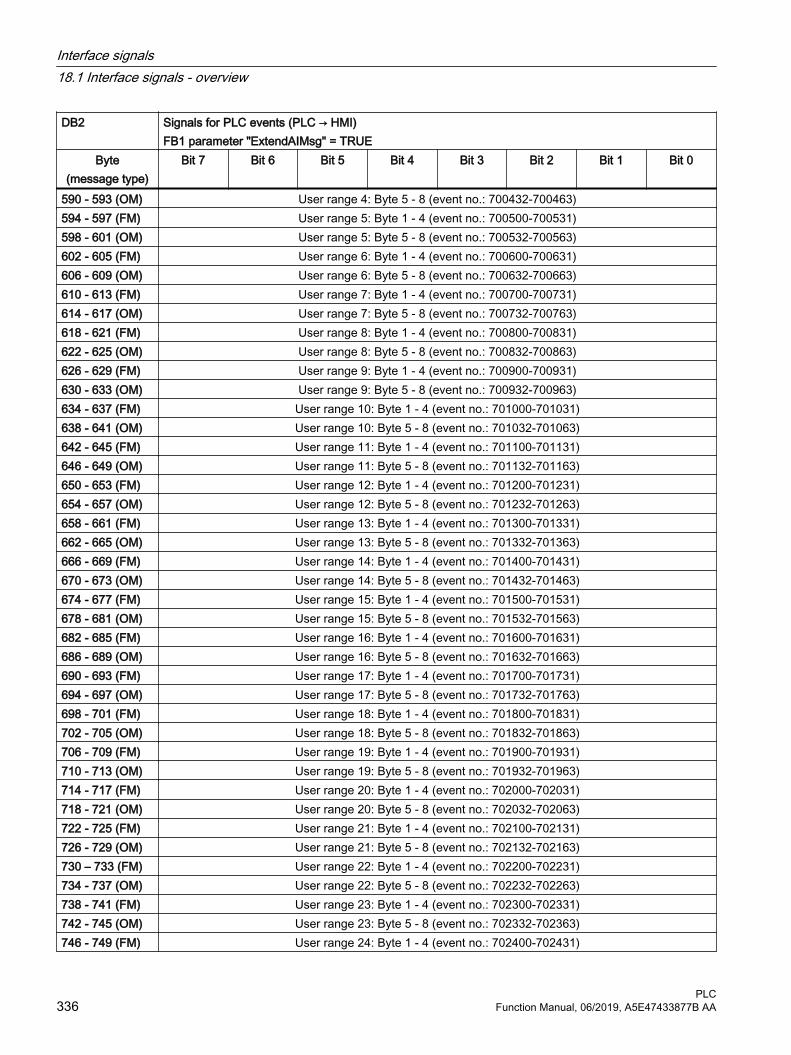
DB2 Signals for PLC events (PLC → HMI) FB1 parameter "ExtendAIMsg" = TRUE
Byte(message type)
Bit 7 Bit 6 Bit 5 Bit 4 Bit 3 Bit 2 Bit 1 Bit 0
590 - 593 (OM) User range 4: Byte 5 - 8 (event no.: 700432-700463)594 - 597 (FM) User range 5: Byte 1 - 4 (event no.: 700500-700531)598 - 601 (OM) User range 5: Byte 5 - 8 (event no.: 700532-700563)602 - 605 (FM) User range 6: Byte 1 - 4 (event no.: 700600-700631)606 - 609 (OM) User range 6: Byte 5 - 8 (event no.: 700632-700663)610 - 613 (FM) User range 7: Byte 1 - 4 (event no.: 700700-700731)614 - 617 (OM) User range 7: Byte 5 - 8 (event no.: 700732-700763)618 - 621 (FM) User range 8: Byte 1 - 4 (event no.: 700800-700831)622 - 625 (OM) User range 8: Byte 5 - 8 (event no.: 700832-700863)626 - 629 (FM) User range 9: Byte 1 - 4 (event no.: 700900-700931)630 - 633 (OM) User range 9: Byte 5 - 8 (event no.: 700932-700963)634 - 637 (FM) User range 10: Byte 1 - 4 (event no.: 701000-701031)638 - 641 (OM) User range 10: Byte 5 - 8 (event no.: 701032-701063)642 - 645 (FM) User range 11: Byte 1 - 4 (event no.: 701100-701131)646 - 649 (OM) User range 11: Byte 5 - 8 (event no.: 701132-701163)650 - 653 (FM) User range 12: Byte 1 - 4 (event no.: 701200-701231)654 - 657 (OM) User range 12: Byte 5 - 8 (event no.: 701232-701263)658 - 661 (FM) User range 13: Byte 1 - 4 (event no.: 701300-701331)662 - 665 (OM) User range 13: Byte 5 - 8 (event no.: 701332-701363)666 - 669 (FM) User range 14: Byte 1 - 4 (event no.: 701400-701431)670 - 673 (OM) User range 14: Byte 5 - 8 (event no.: 701432-701463)674 - 677 (FM) User range 15: Byte 1 - 4 (event no.: 701500-701531)678 - 681 (OM) User range 15: Byte 5 - 8 (event no.: 701532-701563)682 - 685 (FM) User range 16: Byte 1 - 4 (event no.: 701600-701631)686 - 689 (OM) User range 16: Byte 5 - 8 (event no.: 701632-701663)690 - 693 (FM) User range 17: Byte 1 - 4 (event no.: 701700-701731)694 - 697 (OM) User range 17: Byte 5 - 8 (event no.: 701732-701763)698 - 701 (FM) User range 18: Byte 1 - 4 (event no.: 701800-701831)702 - 705 (OM) User range 18: Byte 5 - 8 (event no.: 701832-701863)706 - 709 (FM) User range 19: Byte 1 - 4 (event no.: 701900-701931)710 - 713 (OM) User range 19: Byte 5 - 8 (event no.: 701932-701963)714 - 717 (FM) User range 20: Byte 1 - 4 (event no.: 702000-702031)718 - 721 (OM) User range 20: Byte 5 - 8 (event no.: 702032-702063)722 - 725 (FM) User range 21: Byte 1 - 4 (event no.: 702100-702131)726 - 729 (OM) User range 21: Byte 5 - 8 (event no.: 702132-702163)730 – 733 (FM) User range 22: Byte 1 - 4 (event no.: 702200-702231)734 - 737 (OM) User range 22: Byte 5 - 8 (event no.: 702232-702263)738 - 741 (FM) User range 23: Byte 1 - 4 (event no.: 702300-702331)742 - 745 (OM) User range 23: Byte 5 - 8 (event no.: 702332-702363)746 - 749 (FM) User range 24: Byte 1 - 4 (event no.: 702400-702431)
Interface signals18.1 Interface signals - overview
PLC336 Function Manual, 06/2019, A5E47433877B AA

DB2 Signals for PLC events (PLC → HMI) FB1 parameter "ExtendAIMsg" = TRUE
Byte(message type)
Bit 7 Bit 6 Bit 5 Bit 4 Bit 3 Bit 2 Bit 1 Bit 0
750 - 753 (OM) User range 24: Byte 5 - 8 (event no.: 702432-702463)754 - 757 (FM) User range 25: Byte 1 - 4 (event no.: 702500-702531)758 - 761 (OM) User range 25: Byte 5 - 8 (event no.: 702532-702563)762 - 765 (FM) User range 26: Byte 1 - 4 (event no.: 702600-702631)766 - 769 (OM) User range 26: Byte 5 - 8 (event no.: 702632-702663)770 - 773 (FM) User range 27: Byte 1 - 4 (event no.: 702700-702731)774 - 777 (OM) User range 27: Byte 5 - 8 (event no.: 702732-702763)778 - 781 (FM) User range 28: Byte 1 - 4 (event no.: 702800-702831)782 - 785 (OM) User range 28: Byte 5 - 8 (event no.: 702832-702863)786 - 789 (FM) User range 29: Byte 1 - 4 (event no.: 702900-702931)790 - 793 (OM) User range 29: Byte 5 - 8 (event no.: 702932-702963)794 - 797 (FM) User range 30: Byte 1 - 4 (event no.: 703000-703031)798 - 801 (OM) User range 30: Byte 5 - 8 (event no.: 703032-703063)802 - 805 (FM) User range 31: Byte 1 - 4 (event no.: 703100-703131)806 - 809 (OM) User range 31: Byte 5 - 8 (event no.: 703132-703163)810 - 813 (FM) User area 32: Byte 1 - 4 (event no.: 703200 - 703231)814 - 817 (BM) User area 32: Byte 5 - 8 (event no.: 703232 - 703263)818 - 821 (FM) User area 33: Byte 1 - 4 (event no.: 703300 - 703331)822 - 825 (OM) User area 33: Byte 5 - 8 (event no.: 703332 - 703363)826 - 829 (FM) User area 34: Byte 1 - 4 (event no.: 703400 - 703431)830 - 833 (OM) User area 34: Byte 5 - 8 (event no.: 703432 - 703463)834 - 837 (FM) User area 35: Byte 1 - 4 (event no.: 703500 - 703531)838 - 841 (OM) User area 35: Byte 5 - 8 (event no.: 703532 - 703563)842 - 845 (FM) User area 36: Byte 1 - 4 (event no.: 703600 - 703631)846 - 789 (OM) User area 36: Byte 5 - 8 (event no.: 703632 - 703663)850 - 853 (FM) User area 37: Byte 1 - 4 (event no.: 703700 - 703731)854 - 857 (OM) User area 37: Byte 5 - 8 (event no.: 703732 - 703763)858 - 861 (FM) User area 38: Byte 5 - 8 (event no.: 703800 -703831)862 - 865 (OM) User area 38: Byte 1 - 4 (event no.: 703832 -703863)866 - 869 (FM) User area 39: Byte 5 - 8 (event no.: 703900 -703931)870 - 873 (OM) User area 39: Byte 1 - 4 (event no.: 703932 -703963)874 - 877 (FM) User area 40: Byte 1 - 4 (event no.: 704000-704031)878 - 881 (OM) User area 40: Byte 5 - 8 (event no.: 704032-704063)882 - 885 (FM) User area 41: Byte 1 - 4 (event no.: 704100-704131)886 - 889 (OM) User area 41: Byte 5 - 8 (event no.: 704132-704163)890 - 893 (FM) User area 42: Byte 1 - 4 (event no.: 704200-704231)894 - 897 (OM) User area 42: Byte 5 - 8 (event no.: 704232-704263)898 - 901 (FM) User area 43: Byte 1 - 4 (event no.: 704300-704331)902 - 905 (OM) User area 43: Byte 5 - 8 (event no.: 704332-704363)906 - 909 (FM) User area 44: Byte 1 - 4 (event no.: 704400-704431)
Interface signals18.1 Interface signals - overview
PLCFunction Manual, 06/2019, A5E47433877B AA 337

DB2 Signals for PLC events (PLC → HMI) FB1 parameter "ExtendAIMsg" = TRUE
Byte(message type)
Bit 7 Bit 6 Bit 5 Bit 4 Bit 3 Bit 2 Bit 1 Bit 0
910 - 913 (OM) User area 44: Byte 5 - 8 (event no.: 704432-704463)914 - 917 (FM) User area 45: Byte 1 - 4 (event no.: 704500-704531)918 - 921 (OM) User area 45: Byte 5 - 8 (event no.: 704532-704563)922 - 925 (FM) User area 46: Byte 1 - 4 (event no.: 704600-704631)926 - 929 (OM) User area 46: Byte 5 - 8 (event no.: 704632-704663)930 - 933 (FM) User area 47: Byte 1 - 4 (event no.: 704700-704731)934 - 937 (OM) User area 47: Byte 5 - 8 (event no.: 704732-704763)938 - 941 (FM) User area 48: Byte 1 - 4 (event no.: 704800-704831)942 - 945 (OM) User area 48: Byte 5 - 8 (event no.: 704832-704863)946 - 989 (FM) User area 49: Byte 1 - 4 (event no.: 704900-704931)950 - 953 (OM) User area 49: Byte 5 - 8 (event no.: 704932-704963)954 - 957 (FM) User area 50: Byte 1 - 4 (event no.: 705000-705031)958 - 961 (OM) User area 50: Byte 5 - 8 (event no.: 705032-705063)962 -965 (FM) User area 51: Byte 1 - 4 (event no.: 705100-705131)966 - 969 (OM) User area 51: Byte 5 - 8 (event no.: 705132-705163)970 - 973 (FM) User area 52: Byte 1 - 4 (event no.: 705200-705231)974 - 977 (OM) User area 52: Byte 5 - 8 (event no.: 705232-705263)978 - 981 (FM) User area 53: Byte 1 - 4 (event no.: 705300-705331)982 - 985 (OM) User area 53: Byte 5 - 8 (event no.: 705332-705363)986 - 989 (FM) User area 54: Byte 1 - 4 (event no.: 705400-705431)990 - 993 (OM) User area 54: Byte 5 - 8 (event no.: 705432-705463)994 - 997 (FM) User area 55: Byte 1 - 4 (event no.: 705500-705531)998 - 1001 (OM) User area 55: Byte 5 - 8 (event no.: 705532-705563)1002 - 1005 (FM) User area 56: Byte 1 - 4 (event no.: 705600-705631)1006 - 1009 (OM) User area 56: Byte 5 - 8 (event no.: 705632-705663)1010 -1013 (FM) User area 57: Byte 1 - 4 (event no.: 705700-705731)1014 - 1017 (OM) User area 57: Byte 5 - 8 (event no.: 705732-705763)1018 - 1021 (FM) User area 58: Byte 1 - 4 (event no.: 705800-705831)1022 - 1025 (OM) User area 58: Byte 5 - 8 (event no.: 705832-705863)1026 - 1029 (FM) User area 59: Byte 1 - 4 (event no.: 705900-705931)1030 - 1033 (OM) User area 59: Byte 5 - 8 (event no.: 705932-705963)1034 - 1037 (FM) User area 60: Byte 1 - 4 (event no.: 706000-706031)1038 - 941 (OM) User area 60: Byte 5 - 8 (event no.: 706032-706063)1042 - 1045 (FM) User area 61: Byte 1 - 4 (event no.: 706100-706131)1046 - 1089 (OM) User area 61: Byte 5 - 8 (event no.: 706132-706163)1050 - 1053 (FM) User area 62: Byte 1 - 4 (event no.: 706200-706231)1054 - 1057 (OM) User area 62: Byte 5 - 8 (event no.: 706232-706263)1058 - 1061 (FM) User area 63: Byte 1 - 4 (event no.: 706300-706331)1062 -1065 (BM) User area 63: Byte 5 - 8 (event no.: 706332-706363)
Interface signals18.1 Interface signals - overview
PLC338 Function Manual, 06/2019, A5E47433877B AA

NoteParameterizing user ranges
The number of user ranges (maximum of 64) can be parameterized using FB 1 "MsgUser".
18.1.7 Signals from/to the NC, PLC and operating software
18.1.7.1 DB10, onboard inputs and outputs of the NC
Table 18-40 DB10, onboard inputs and outputs of the NC
DB10 Signals to the NC (PLC → NC)Byte Bit 7 Bit 6 Bit 5 Bit 4 Bit 3 Bit 2 Bit 1 Bit 0DBB0 Disable of the digital NC inputs
see also (Page 434)Input without hardware Input onboard
8 7 6 5 4 3 2 1DBB1 Setting of the digital NC inputs from the PLC
see also (Page 435)Input without hardware Input onboard
8 7 6 5 4 3 2 1DBB2 - DBB3
Not assigned
DBB4 Disable of the digital NC outputs see also (Page 435)
Output without hardware Output onboard8 7 6 5 4 3 2 1
DBB5 Overwrite mask of the digital NC outputs see also (Page 436)
Output without hardware Output onboard8 7 6 5 4 3 2 1
DBB6 Setting value of the digital NC outputs from the PLC see also (Page 436)
Output without hardware Output onboard8 7 6 5 4 3 2 1
DBB7 Input mask of the digital NC outputs see also (Page 437)
Output without hardware Output onboard8 7 6 5 4 3 2 1
Interface signals18.1 Interface signals - overview
PLCFunction Manual, 06/2019, A5E47433877B AA 339

DB10 Signals to the NC (PLC → NC)Byte Bit 7 Bit 6 Bit 5 Bit 4 Bit 3 Bit 2 Bit 1 Bit 0DBB8 - DBB29
Machine axis numbers table for FC 19, FC 24, FC 25, FC 26 (1st MCP)
DBW30 Upper limit of the machine axis numbers for FC 19, FC 24 (1st MCP)With 0, the maximum number of machine axis numbers applies
DBB32 -DBB53
Machine axis numbers table for FC 19, FB 24, FB 25, FB 26 (2nd MCP)
DBW54 Upper limit of the machine axis numbers for FC 19, FC 24 (2nd MCP)With 0, the maximum number of machine axis numbers applies
18.1.7.2 DB10, general signals to the NC
Table 18-41 DB10, general signals to the NC
DB10 Signals to the NC (PLC → NC)Byte Bit 7 Bit 6 Bit 5 Bit 4 Bit 3 Bit 2 Bit 1 Bit 0DBB56 Key-operated switch position
see also (Page 438) Acknowl‐
edge Emer‐gency Stop
see also
(Page 438)
Emergency Stop
see also
(Page 438)
Bit 3 Bit 2 Bit 1 Bit 0
DBB57 Reserved INC inputs in the mode
group range ac‐
tiveDBB58 Collision avoidance: Deactivate protection area group
see also (Page 439)For operating mode: JOG For operating mode: AUTOMATIC
Workpieces Workholder Tools Machine Workpieces Workholder Tools MachineDBB59
Interface signals18.1 Interface signals - overview
PLC340 Function Manual, 06/2019, A5E47433877B AA

18.1.7.3 DB10, onboard inputs and outputs from the NC/operating software
Table 18-42 DB10, onboard inputs and outputs from the NC/operating software
DB10 Signals from the NC (NC → PLC)Byte Bit 7 Bit 6 Bit 5 Bit 4 Bit 3 Bit 2 Bit 1 Bit 0DBB60 Actual value of the digital NC inputs Actual value of the digital onboard inputs of the NC
see also (Page 440)Input 8 Input 7 Input 6 Input 5 Input 4 Input 3 Input 2 Input 1
DBB61 - DBB63
DBB64 Setpoint for the digital outputs of the NC without hard‐ware
Setpoint for the digital onboard outputs of the NCsee also (Page 441)
Output 8 Output 7 Output 6 Output 5 Output 4 Output 3 Output 2 Output 1DBB65 - DBB67
DBB68 Handwheel 1 is operatedDBB69 Handwheel 2 is operatedDBB70 Handwheel 3 is operatedDBB71 Change counter, inch/metric system of unitsDBB72HT 8 → op‐erating soft‐ware
Status of the displayed actual value screen (1st MCP)Traversing keys shown
MCS / WCS Display val‐id
DBB73HT 8 → op‐erating soft‐ware
Status of the displayed actual value screen (2nd MCP)Traversing keys shown
MCS / WCS Display val‐id
DBB74 - DBB79HT 8 → op‐erating soft‐ware
Machine axis numbers of the displayed axes (1st MCP)MCPT1AxisFromHMI
DBB80 - DBB85HT 8 → op‐erating soft‐ware
Machine axis numbers of the displayed axes (2nd MCP)MCP2AxisFromHMI
DBW86 Reserved
DBB88 Reserved
Interface signals18.1 Interface signals - overview
PLCFunction Manual, 06/2019, A5E47433877B AA 341

18.1.7.4 DB10, selection and status signals from the operating software
Table 18-43 DB10, selection and status signals from the operating software
DB10 Signals from the NC (NC → PLC)Byte Bit 7 Bit 6 Bit 5 Bit 4 Bit 3 Bit 2 Bit 1 Bit 0DBB90SINUMER‐IK Inte‐grate → PLC
DBB91PLC → SIN‐UMERIK In‐tegrate
DBB92GP → PLC
Suppress fault message in case of fail‐ure
Slave OK
PN bus DP1 bus MPI/DP bus
PN bus DP1 bus MPI/DP bus
DBB93Operating soft‐ware → PLC
Deactivate collision avoidanceJOG mode AUTO mode
Workpieces Workholder Tools Machine Workpieces Workholder Tools Machine
DBB94 AlarmDirect keys 2
Communi‐cation error
Alarm, di‐rect keys 1Communi‐cation error
DBB95
DBB96Operating soft‐ware → PLC
Set language ID of the operating software
DBB97Operating soft‐ware → PLC
Channel number for handwheel 1 see also (Page 442)
D C B A
DBB98Operating soft‐ware → PLC
Channel number for handwheel 2 see also (Page 443)
D C B A
DBB99Operating soft‐ware → PLC
Channel number for handwheel 3 see also (Page 443)
D C B A
Interface signals18.1 Interface signals - overview
PLC342 Function Manual, 06/2019, A5E47433877B AA

DB10 Signals from the NC (NC → PLC)Byte Bit 7 Bit 6 Bit 5 Bit 4 Bit 3 Bit 2 Bit 1 Bit 0DBB100Operating soft‐ware → PLC
Axis number for handwheel 1 see also (Page 444)
Machine axis
see also
(Page 446)
Handwheel 1 selected
see also
(Page 445)
Define handwheel 1 as con‐tour hand‐
wheelsee
also (Page 444)
E D C B A
DBB101Operating soft‐ware → PLC
Axis number for handwheel 2see also (Page 446)
Machine axis
see also
(Page 447)
Handwheel 2 selected
see also
(Page 446)
Define handwheel 2 as con‐tour hand‐
wheelsee
also (Page 446)
E D C B A
DBB102Operating soft‐ware → PLC
Axis number for handwheel 3 see also (Page 447)
Machine axis
see also
(Page 447)
Handwheel 3 selected
see also
(Page 447)
Define handwheel 3 as con‐tour hand‐
wheelsee
also (Page 447)
E D C B A
DBB103Operating soft‐ware → PLC
Operating software battery alarm
see also
(Page 448)
Operating software tempera‐ture limit
see also
(Page 448)
AT box ready
see also
(Page 447)
Operating software
fan monitor‐ing
Operating software monitor hard disk
Remote di‐agnostics
activesee
also (Page 447)
Interface signals18.1 Interface signals - overview
PLCFunction Manual, 06/2019, A5E47433877B AA 343

18.1.7.5 DB10, general signals from the NC
Table 18-44 DB10, general signals to the PLC
DB10 Signals to the PLCByte Bit 7 Bit 6 Bit 5 Bit 4 Bit 3 Bit 2 Bit 1 Bit 0DBB104GP → PLC
NC CPU: Ready1)
see also
(Page 448)
1st OB1 cy‐cle
Op2Key ready
Op1Key ready
HHU ready MCP 2 ready
MCP 1 ready
DBB105GP → PLC
TOOLMAN:Command
CancelDBB106NC → PLC
Emergency Stop: Active
see also
(Page 449)
Collision avoidance:Protection area moni‐toring active
DBB107NC → PLC
Inch sys‐tem of units
NCU link: Active
see also
(Page 449)
Measuring input activatedsee also (Page 449)
Pushbutton 2
Pushbutton 1
DBB108NC → PLC
NC readysee
also (Page 450)
Drive ready see
also (Page 450)
Drives in cy‐clic opera‐
tionsee
also (Page 450)
Operating software
readysee
also (Page 450)
Operator panel at
MPI: "ready"
Operator panel 2: "ready"
DBB109NC → PLC
NC bat‐tery alarm
see also
(Page 452)
Air temper‐ature alarm
see also
(Page 452)
Heat sink tempera‐ture NCU
alarmsee
also (Page 451)
PC operat‐ing system
error
NC alarm is active
see also
(Page 451)
DBB110NC → PLC
Software cam minussee also (Page 452)
7 8 5 4 3 2 1 0DBB111NC → PLC
Software cam minussee also (Page 452)
15 14 13 12 11 10 9 8DBB112NC → PLC
Software cam minussee also (Page 452)
23 22 21 20 19 18 17 16
Interface signals18.1 Interface signals - overview
PLC344 Function Manual, 06/2019, A5E47433877B AA

DB10 Signals to the PLCByte Bit 7 Bit 6 Bit 5 Bit 4 Bit 3 Bit 2 Bit 1 Bit 0DBB113NC → PLC
Software cam minussee also (Page 452)
31 30 29 28 27 26 25 24DBB114NC → PLC
Software cam plussee also (Page 453)
7 6 5 4 3 2 1 0DBB115NC → PLC
Software cam plussee also (Page 453)
15 14 13 12 11 10 9 8DBB116NC → PLC
Software cam plussee also (Page 453)
23 22 21 20 19 18 17 16DBB117NC → PLC
Software cam plussee also (Page 453)
31 30 29 28 27 26 25 24DBB118-DBB121SINUMERIK Integrate → PLC
SINUMERIK Integrate data
1) DB10 DBX104.7 (NC CPU: ready) The signal should be included in the machine safety circuit.
18.1.7.6 DB10, external digital NC inputs
Table 18-45 DB10, external digital NC inputs
DB10 Signals to the NC (PLC → NC)Byte Bit 7 Bit 6 Bit 5 Bit 4 Bit 3 Bit 2 Bit 1 Bit 0DBB122 Disable of the external digital NC inputs
see also (Page 454)16 15 14 13 12 11 10 9
DBB123 Values from the PLC for the external digital NC inputssee also (Page 454)
16 15 14 13 12 11 10 9DBB124 Disable of the external digital NC inputs
see also (Page 454)24 23 22 21 20 19 18 17
DBB125 Values from the PLC for the external digital NC inputssee also (Page 455)
24 23 22 21 20 19 18 17
Interface signals18.1 Interface signals - overview
PLCFunction Manual, 06/2019, A5E47433877B AA 345

DB10 Signals to the NC (PLC → NC)Byte Bit 7 Bit 6 Bit 5 Bit 4 Bit 3 Bit 2 Bit 1 Bit 0DBB126 Disable of the external digital NC inputs
see also (Page 455)32 31 30 29 28 27 26 25
DBB127 Values from the PLC for the external digital NC inputssee also (Page 456)
32 31 30 29 28 27 26 25DBB128 Disable of the external digital NC inputs
see also (Page 456)40 39 38 37 36 35 34 33
DBB129 Values from the PLC for the external digital NC inputssee also (Page 457)
40 39 38 37 36 35 34 33
18.1.7.7 DB10, external digital NC outputs
Table 18-46 DB10, external digital NC outputs
DB10 Signals to the NC (PLC → NC)Byte Bit 7 Bit 6 Bit 5 Bit 4 Bit 3 Bit 2 Bit 1 Bit 0DBB130 Disable of the external digital NC outputs
see also (Page 457)16 15 14 13 12 11 10 9
DBB131 Overwrite mask for the external digital NC outputssee also (Page 457)
16 15 14 13 12 11 10 9DBB132 Value from the PLC for the external digital NC outputs
see also (Page 458)16 15 14 13 12 11 10 9
DBB133 Input mask for the external digital NC outputssee also (Page 459)
16 15 14 13 12 11 10 9DBB134 Disable of the external digital NC outputs
see also (Page 459)24 23 22 21 20 19 18 17
DBB135 Overwrite mask for the external digital NC outputssee also (Page 460)
24 23 22 21 20 19 18 17DBB136 Value from the PLC for the external digital NC outputs
see also (Page 460)24 23 22 21 20 19 18 17
Interface signals18.1 Interface signals - overview
PLC346 Function Manual, 06/2019, A5E47433877B AA

DB10 Signals to the NC (PLC → NC)Byte Bit 7 Bit 6 Bit 5 Bit 4 Bit 3 Bit 2 Bit 1 Bit 0DBB137 Input mask for the external digital NC outputs
see also (Page 461)24 23 22 21 20 19 18 17
DBB138 Disable of the external digital NC outputssee also (Page 461)
32 31 30 29 28 27 26 25DBB139 Overwrite mask for the external digital NC outputs
see also (Page 462)32 31 30 29 28 27 26 25
DBB140 Value from the PLC for the external digital NC outputssee also (Page 463)
32 31 30 29 28 27 26 25DBB141 Input mask for the external digital NC outputs
see also (Page 463)32 31 30 29 28 27 26 25
DBB142 Disable of the external digital NC outputssee also (Page 464)
40 39 38 37 36 35 34 33DBB143 Overwrite mask for the external digital NC outputs
see also (Page 464)40 39 38 37 36 35 34 33
DBB144 Value from the PLC for the external digital NC outputssee also (Page 465)
40 39 38 37 36 35 34 33DBB145 Input mask for the external digital NC outputs
see also (Page 466)40 39 38 37 36 35 34 33
18.1.7.8 DB10, external analog NC inputs
Table 18-47 DB10, external analog NC inputs
DB10 Signals to the NC (PLC → NC)Byte Bit 7 Bit 6 Bit 5 Bit 4 Bit 3 Bit 2 Bit 1 Bit 0DBB146 Analog NC inputs disabled
see also (Page 466)Bit 8 Bit 7 Bit 6 Bit 5 Bit 4 Bit 3 Bit 2 Bit 1
DBB147 Input analog value input for the NC from the PLCsee also (Page 467)
Bit 8 Bit 7 Bit 6 Bit 5 Bit 4 Bit 3 Bit 2 Bit 1DBW148 Setpoint from the PLC for analog input 1 of the NC
Interface signals18.1 Interface signals - overview
PLCFunction Manual, 06/2019, A5E47433877B AA 347

DB10 Signals to the NC (PLC → NC)Byte Bit 7 Bit 6 Bit 5 Bit 4 Bit 3 Bit 2 Bit 1 Bit 0DBW150 Setpoint from the PLC for analog input 2 of the NC
see also (Page 467)DBW152 Setpoint from the PLC for analog input 3 of the NC
see also (Page 467)DBW154 Setpoint from the PLC for analog input 4 of the NC
see also (Page 467)DBW156 Setpoint from the PLC for analog input 5 of the NC
see also (Page 467)DBW158 Setpoint from the PLC for analog input 6 of the NC
see also (Page 467)DBW160 Setpoint from the PLC for analog input 7 of the NC
see also (Page 467)DBW162 Setpoint from the PLC for analog input 8 of the NC
see also (Page 467)DBW164
18.1.7.9 DB10, external analog NC outputs
Table 18-48 DB10, external analog NC outputs
DB10 Signals to the NC (PLC → NC)Byte Bit 7 Bit 6 Bit 5 Bit 4 Bit 3 Bit 2 Bit 1 Bit 0DBB166 Overwrite mask for the analog NC outputs
see also (Page 467)8 7 6 5 4 3 2 1
DBB167 Input mask for the analog NC outputssee also (Page 468)
8 7 6 5 4 3 2 1DBB168 Analog NC outputs disabled
see also (Page 469)8 7 6 5 4 3 2 1
DBB169 Reserved
DBW170 Setpoint from the PLC for analog output 1 of the NCsee also (Page 469)
DBW172 Setpoint from the PLC for analog output 2 of the NCsee also (Page 469)
DBW174 Setpoint from the PLC for analog output 3 of the NCsee also (Page 469)
DBW176 Setpoint from the PLC for analog output 4 of the NCsee also (Page 469)
Interface signals18.1 Interface signals - overview
PLC348 Function Manual, 06/2019, A5E47433877B AA

DB10 Signals to the NC (PLC → NC)Byte Bit 7 Bit 6 Bit 5 Bit 4 Bit 3 Bit 2 Bit 1 Bit 0DBW178 Setpoint from the PLC for analog output 5 of the NC
see also (Page 469)DBW180 Setpoint from the PLC for analog output 6 of the NC
see also (Page 469)DBW182 Setpoint from the PLC for analog output 7 of the NC
see also (Page 469)DBW184 Setpoint from the PLC for analog output 8 of the NC
see also (Page 469)
18.1.7.10 DB10, external digital NC inputs and outputs
Table 18-49 DB10, external digital NC inputs and outputs
DB10 Signals from the NC (NC → PLC)Byte Bit 7 Bit 6 Bit 5 Bit 4 Bit 3 Bit 2 Bit 1 Bit 0DBB186 Actual value of the external digital NC inputs
see also (Page 470)16 15 14 13 12 11 10 9
DBB187 Actual value of the external digital NC inputssee also (Page 470)
24 23 22 21 20 19 18 17DBB188 Actual value of the external digital NC inputs
see also (Page 471)32 31 30 29 28 27 26 25
DBB189 Actual value of the external digital NC inputssee also (Page 471)
40 39 38 37 36 35 34 33DBB190 NC setpoint for the external digital NC outputs
see also (Page 472)16 15 14 13 12 11 10 9
DBB191 NC setpoint for the external digital NC outputssee also (Page 472)
24 23 22 21 20 19 18 17DBB192 NC setpoint for the external digital NC outputs
see also (Page 473)32 31 30 29 28 27 26 25
DBB193 NC setpoint for the external digital NC outputssee also (Page 473)
40 39 38 37 36 35 34 33
Interface signals18.1 Interface signals - overview
PLCFunction Manual, 06/2019, A5E47433877B AA 349

18.1.7.11 DB10, analog NC inputs and outputs
Table 18-50 DB10, analog NC inputs and outputs
DB10 Signals from the NC (NC → PLC)Byte Bit 7 Bit 6 Bit 5 Bit 4 Bit 3 Bit 2 Bit 1 Bit 0DBW194 Actual value of analog input 1 of the NC
see also (Page 474)DBW196 Actual value of analog input 2 of the NC
see also (Page 474)DBW198 Actual value of analog input 3 of the NC
see also (Page 474)DBW200 Actual value of analog input 4 of the NC
see also (Page 474)DBW202 Actual value of analog input 5 of the NC
see also (Page 474)DBW204 Actual value of analog input 6 of the NC
see also (Page 474)DBW206 Actual value of analog input 7 of the NC
see also (Page 474)DBW208 Actual value of analog input 8 of the NC
see also (Page 474)DBW210 Setpoint of analog output 1 of the NC
see also (Page 474)DBW212 Setpoint of analog output 2 of the NC
see also (Page 474)DBW214 Setpoint of analog output 3 of the NC
see also (Page 474)DBW216 Setpoint of analog output 4 of the NC
see also (Page 474)DBW218 Setpoint of analog output 5 of the NC
see also (Page 474)DBW220 Setpoint of analog output 6 of the NC
see also (Page 474)DBW222 Setpoint of analog output 7 of the NC
see also (Page 474)DBW224 Setpoint of analog output 8 of the NC
see also (Page 474)
Interface signals18.1 Interface signals - overview
PLC350 Function Manual, 06/2019, A5E47433877B AA

18.1.7.12 DB10, collision avoidance: Protection area active
Table 18-51 DB10, collision avoidance: Protection zone active
DB10 Signals from the NC (NC → PLC)Byte Bit 7 Bit 6 Bit 5 Bit 4 Bit 3 Bit 2 Bit 1 Bit 0DBB226 Collision avoidance: Protection zone active (bit)
see also (Page 475)7 6 5 4 3 2 1 0
DBB227 Collision avoidance: Protection zone active (bit)see also (Page 475)
15 14 13 12 11 10 9 8DBB228 Collision avoidance: Protection zone active (bit)
see also (Page 475)23 22 21 20 19 18 17 16
DBB229 Collision avoidance: Protection zone active (bit)see also (Page 475)
31 30 29 28 27 26 25 24DBB230 Collision avoidance: Protection zone active (bit)
see also (Page 475)39 38 37 36 35 34 33 32
DBB231 Collision avoidance: Protection zone active (bit)see also (Page 475)
47 46 45 44 43 42 41 40DBB232 Collision avoidance: Protection zone active (bit)
see also (Page 475)55 54 53 52 51 50 49 48
DBB233 Collision avoidance: Protection zone active (bit)see also (Page 475)
63 62 61 60 59 58 57 56
18.1.7.13 DB10, collision avoidance: Activate protection area
Table 18-52 DB10, collision avoidance: Activate protection zone
DB10 Signals from the PLC (PLC → NC)Byte Bit 7 Bit 6 Bit 5 Bit 4 Bit 3 Bit 2 Bit 1 Bit 0DBB234 Collision avoidance: Activate protection zone (bit)
see also (Page 476)7 6 5 4 3 2 1 0
DBB235 Collision avoidance: Activate protection zone (bit)see also (Page 476)
15 14 13 12 11 10 9 8
Interface signals18.1 Interface signals - overview
PLCFunction Manual, 06/2019, A5E47433877B AA 351

DB10 Signals from the PLC (PLC → NC)Byte Bit 7 Bit 6 Bit 5 Bit 4 Bit 3 Bit 2 Bit 1 Bit 0DBB236 Collision avoidance: Activate protection zone (bit)
see also (Page 476)23 22 21 20 19 18 17 16
DBB237 Collision avoidance: Activate protection zone (bit)see also (Page 476)
31 30 29 28 27 26 25 24DBB238 Collision avoidance: Activate protection zone (bit)
see also (Page 476)39 38 37 36 35 34 33 32
DBB239 Collision avoidance: Activate protection zone (bit)see also (Page 476)
47 46 45 44 43 42 41 40DBB240 Collision avoidance: Activate protection zone (bit)
see also (Page 476)55 54 53 52 51 50 49 48
DBB241 Collision avoidance: Activate protection zone (bit)see also (Page 476)
63 62 61 60 59 58 57 56
18.1.7.14 DB10, extension, handwheel signals from the NC
Table 18-53 DB10, extension, handwheel signals from the NC
DB10 Signals from the NC (NC → PLC)Byte Bit 7 Bit 6 Bit 5 Bit 4 Bit 3 Bit 2 Bit 1 Bit 0DBB242 Handwheel 4 is moved DBB243 Handwheel 5 is movedDBB244 Handwheel 6 is moved DBB245 Ethernet handwheel is stationary
see also (Page 476)Handwheel
6Handwheel
5Handwheel
4Handwheel
3Handwheel
2Handwheel
1DBB246 Reserved
Interface signals18.1 Interface signals - overview
PLC352 Function Manual, 06/2019, A5E47433877B AA

18.1.7.15 DB10, interface robot status.
Table 18-54 DB10, signals from the robot
DB10 Signals from the PLC (PLC → NC)Byte Bit 7 Bit 6 Bit 5 Bit 4 Bit 3 Bit 2 Bit 1 Bit 0DBB248 Robot status byte 0DBB249 Robot status byte 1DBB250 Robot status byte 2DBB251 Robot status byte 3DBB252 Robot status byte 4DBB253 Robot status byte 5DBB254 Robot status byte 6DBB255 Robot status byte 7
18.1.7.16 DB10, interface robot status
Table 18-55 DB10, signals to the robot
DB10 Signals from the NC (NC → PLC)Byte Bit 7 Bit 6 Bit 5 Bit 4 Bit 3 Bit 2 Bit 1 Bit 0DBB256 Robot control byte 0DBB257 Robot control byte 1DBB258 Robot control byte 2DBB259 Robot control byte 3DBB260 Robot control byte 4DBB261 Robot control byte 5DBB262 Robot control byte 6DBB263 Robot control byte 7
18.1.8 Mode group-specific signals
18.1.8.1 DB11, mode signals 1 to the NCThe start address of a mode group interface can be calculated as follows:
Interface signals18.1 Interface signals - overview
PLCFunction Manual, 06/2019, A5E47433877B AA 353

Start address = 20 * (n - 1), with n = mode group number = 1, 2, 3, ...
Table 18-56 DB11, mode signals mode group 1 to NC
DB11 Signals to mode group 1 (PLC → NC)Byte Bit 7 Bit 6 Bit 5 Bit 4 Bit 3 Bit 2 Bit 1 Bit 0DBB0 Mode
group resetsee
also (Page 480)
Mode group stop axes plus spindles
see also
(Page 479)
Mode group Stop
see also
(Page 479)
Mode change dis‐
ablesee
also (Page 478)
Mode: RequirementJOG
see also
(Page 478)
MDIsee
also (Page 477)
AUTO see
also (Page 477)
DBB1 Single block Machine function: RequirementType A
see also
(Page 482)
Type Bsee
also (Page 481)
REFsee
also (Page 481)
REPOSsee
also (Page 481)
TEACH INsee
also (Page 480)
DBB2 Machine function: RequirementNote: The interface must be enabled explicitly: DB10 DBX57.0 (Page 340) = 1
Continuous traversing
INCvar INC10000 INC1000 INC100 INC10 INC1
DBB3
18.1.8.2 DB11, mode signals 1 from the NC
Table 18-57 DB11, mode signals mode group 1 from NC
DB11 Signals from mode group 1 (NC → PLC)Byte Bit 7 Bit 6 Bit 5 Bit 4 Bit 3 Bit 2 Bit 1 Bit 0DBB4Operating software → PLC
Mode strobeJOG
see also
(Page 483)
MDIsee
also (Page 483)
AUTOsee
also (Page 483)
DBB5Operating software → PLC
Machine function strobeREF
see also
(Page 484)
REPOSsee
also (Page 484)
TEACH INsee
also (Page 483)
DBB6 All chan‐nels in the reset state
see also
(Page 486)
NC internal JOG active
/FB-K1/
Mode group reset performed
/FB-K1/
Mode group ready
see also
(Page 485)
Active operating modeJOG
see also
(Page 485)
MDIsee
also (Page 485)
AUTOsee
also (Page 484)
Interface signals18.1 Interface signals - overview
PLC354 Function Manual, 06/2019, A5E47433877B AA

DB11 Signals from mode group 1 (NC → PLC)Byte Bit 7 Bit 6 Bit 5 Bit 4 Bit 3 Bit 2 Bit 1 Bit 0DBB7 Active machine function
REFsee
also (Page 486)
REPOSsee
also (Page 486)
TEACH INsee
also (Page 486)
DBB8 Machine functions: SelectionNote: The interface must be enabled explicitly: DB10 DBX57.0 (Page 340)= 1
Continuous traversing
active
INCvar INC10000 INC1000 INC100 INC10 INC1
DBB9
Table 18-58 DB11, mode signals mode group 1 from the HMI
DB11 Signals to mode group 1 (HMI → PLC)Byte Bit 7 Bit 6 Bit 5 Bit 4 Bit 3 Bit 2 Bit 1 Bit 0DBB10Operating software → PLC
Machine functions Continuous
traversing active
INCvar INC10000 INC1000 INC100 INC10 INC1
DBB11
18.1.8.3 DB11, mode signals 2 to the NC
Table 18-59 DB11, mode signals mode group 2 to NC
DB11 Signals to mode group 2 (PLC → NC)Byte Bit 7 Bit 6 Bit 5 Bit 4 Bit 3 Bit 2 Bit 1 Bit 0DBB20 Mode
group reset
Mode group Stop axes plus spindles
Mode group Stop
Mode change dis‐
able
Mode: RequirementJOG MDI AUTO
DBB21 Single block Machine function: RequirementType A Type B REF REPOS TEACH IN
DBB22 Machine function: RequirementNote: The interface must be enabled explicitly: DB10 DBX57.0 = (Page 340) 1
Continuous traversing
INCvar INC10000 INC1000 INC100 INC10 INC1
DBB23
Interface signals18.1 Interface signals - overview
PLCFunction Manual, 06/2019, A5E47433877B AA 355
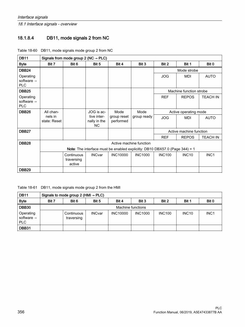
18.1.8.4 DB11, mode signals 2 from NC
Table 18-60 DB11, mode signals mode group 2 from NC
DB11 Signals from mode group 2 (NC → PLC)Byte Bit 7 Bit 6 Bit 5 Bit 4 Bit 3 Bit 2 Bit 1 Bit 0DBB24Operating software → PLC
Mode strobeJOG MDI AUTO
DBB25Operating software → PLC
Machine function strobeREF REPOS TEACH IN
DBB26 All chan‐nels in
state: Reset
JOG is ac‐tive inter‐
nally in the NC
Mode group reset performed
Mode group ready
Active operating modeJOG MDI AUTO
DBB27 Active machine functionREF REPOS TEACH IN
DBB28 Active machine functionNote: The interface must be enabled explicitly: DB10 DBX57.0 (Page 344) = 1
Continuous traversing
active
INCvar INC10000 INC1000 INC100 INC10 INC1
DBB29
Table 18-61 DB11, mode signals mode group 2 from the HMI
DB11 Signals to mode group 2 (HMI → PLC)Byte Bit 7 Bit 6 Bit 5 Bit 4 Bit 3 Bit 2 Bit 1 Bit 0DBB30Operating software → PLC
Machine functions Continuous
traversingINCvar INC10000 INC1000 INC100 INC10 INC1
DBB31
Interface signals18.1 Interface signals - overview
PLC356 Function Manual, 06/2019, A5E47433877B AA

18.1.9 Safety Integrated (SPL)
18.1.9.1 DB18, parameterization part
Table 18-62 DB18, parameterization part
DB18 SPL signals (PLC → PLC)Byte Bit 7 Bit 6 Bit 5 Bit 4 Bit 3 Bit 2 Bit 1 Bit 0DBB0 - DBB34
DBB36 Stop Esee
also (Page 487)
SPL ready see
also (Page 487)
DBB37
18.1.9.2 DB18, data area / errors
Table 18-63 DB18, data area / errors
DB18/FBSsl/
SPL signals (PLC ←→ NC)
Byte Bit 7 Bit 6 Bit 5 Bit 4 Bit 3 Bit 2 Bit 1 Bit 0 Data area of the SPL inputs/outputsDBB38 - DBB41
SPL_DATA.INSEP [1..32]see also (Page 487)
DBB42 - DBB45
SPL_DATA.INSEP [33..64]see also (Page 488)
DBB46 - DBB49
SPL_DATA.OUTSEP [1..32]see also (Page 488)
DBB50 - DBB53
SPL_DATA.OUTSEP [33..64]
Data area for user SPLDBB54 - DBB57
SPL_DATA.INSIP [1..32]
DBB58 - DBB61
SPL_DATA.INSIP [33..64]
DBB62 - DBB65
SPL_DATA.OUTSIP [1..32]
DBB66 - DBB69
SPL_DATA.OUTSIP [33..64]
Interface signals18.1 Interface signals - overview
PLCFunction Manual, 06/2019, A5E47433877B AA 357

DB18/FBSsl/
SPL signals (PLC ←→ NC)
Byte Bit 7 Bit 6 Bit 5 Bit 4 Bit 3 Bit 2 Bit 1 Bit 0DBB70 - DBB73
SPL_DATA.MARKERSIP [1..32]
DBB74 - DBB77
SPL_DATA.MARKERSIP [33..64]
Difference in signal level NC - PLC for diagnosticsDBB78 - DBB81
-DBB81 SPL_DELTA.INSEP [1..32]
DBB82 - DBB85
SPL_DELTA.INSEP [33..64]
DBB86 - DBB89
SPL_DELTA.OUTSEP [1..32]
DBB90 - DBB93
SPL_DELTA.OUTSEP [33..64]
DBB94 - DBB97
SPL_DELTA.INSIP [1..32]
DBB98 - DBB101
SPL_DELTA.INSIP [33..64]
DBB102-DBB105
SPL_DELTA.OUTSIP [1..32]
DBB106 - DBB109
SPL_DELTA.OUTSIP [33..64]
DBB110 - DBB113
SPL_DELTA.MARKERSIP [1..32]
DBB114 - DBB117
SPL_DELTA.MARKERSIP [33..64]
DBB118 CMDSIDBB119 NC signals
a stop to the PLC
Systemer‐ror CDC
Crosswise data com‐parison er‐ror, SPL
protection status
PROFIsafe communi‐
cation error
DBD120 STATSI0 = no error
Crosswise data comparison error trippedDBD124 CDC stack level display
(diagnostics capability: How many SPL signals currently have a different level)
Interface signals18.1 Interface signals - overview
PLC358 Function Manual, 06/2019, A5E47433877B AA
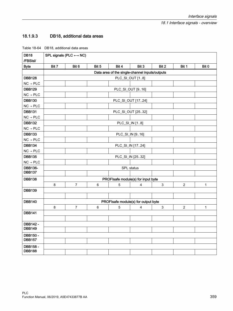
18.1.9.3 DB18, additional data areas
Table 18-64 DB18, additional data areas
DB18/FBSIsl/
SPL signals (PLC ←→ NC)
Byte Bit 7 Bit 6 Bit 5 Bit 4 Bit 3 Bit 2 Bit 1 Bit 0 Data area of the single-channel inputs/outputsDBB128NC → PLC
PLC_SI_OUT [1..8]
DBB129NC → PLC
PLC_SI_OUT [9..16]
DBB130NC → PLC
PLC_SI_OUT [17..24]
DBB131NC → PLC
PLC_SI_OUT [25..32]
DBB132NC → PLC
PLC_SI_IN [1..8]
DBB133NC → PLC
PLC_SI_IN [9..16]
DBB134NC → PLC
PLC_SI_IN [17..24]
DBB135NC → PLC
PLC_SI_IN [25..32]
DBB136-DBB137
SPL status
DBB138 PROFIsafe module(s) for input byte8 7 6 5 4 3 2 1
DBB139
DBB140 PROFIsafe module(s) for output byte8 7 6 5 4 3 2 1
DBB141
DBB142 - DBB149
DBB150 -DBB157
DBB158 - DBB188
Interface signals18.1 Interface signals - overview
PLCFunction Manual, 06/2019, A5E47433877B AA 359

18.1.9.4 DB18, F_SENDDP sender
Table 18-65 DB18, F_SENDDP sender
DB18/FBSIsl/
SPL signals (PLC ←→ NC)
Byte Bit 7 Bit 6 Bit 5 Bit 4 Bit 3 Bit 2 Bit 1 Bit 0 1st F_SENDDP interface: FSDP[1]DBW190 ERR_REACDBB192 SUBS_ON ERRORDBB193 DBW194 DIAGDBW196 RETVAL14DBW198 RETVAL15 2nd F_SENDDP interface: FSDP[2]DBW200 ERR_REACDBB202 SUBS_ON ERRORDBB203 DBW204 DIAGDBW206 RETVAL14DBW208 RETVAL15 3rd F_SENDDP interface: FSDP[3]DBW210 ERR_REACDBB212 SUBS_ON ERRORDBB213 DBW214 DIAGDBW216 RETVAL14DBW218 RETVAL15
18.1.9.5 DB18, F_SENDDP receiver
Table 18-66 DB18, F_SENDDP receiver
DB18/FBSIsl/
SPL signals (PLC ←→ NC)
Byte Bit 7 Bit 6 Bit 5 Bit 4 Bit 3 Bit 2 Bit 1 Bit 0 1st F_RECVDP interface: FRDP[1]
(SUBS)DBB220 7 6 5 4 3 2 1 0DBB221 15 14 13 12 11 10 9 8DBB222 REACDBB224 ACK_REIDBB225 SEND
MODEACK_REQ SUBS_ON ERROR
Interface signals18.1 Interface signals - overview
PLC360 Function Manual, 06/2019, A5E47433877B AA
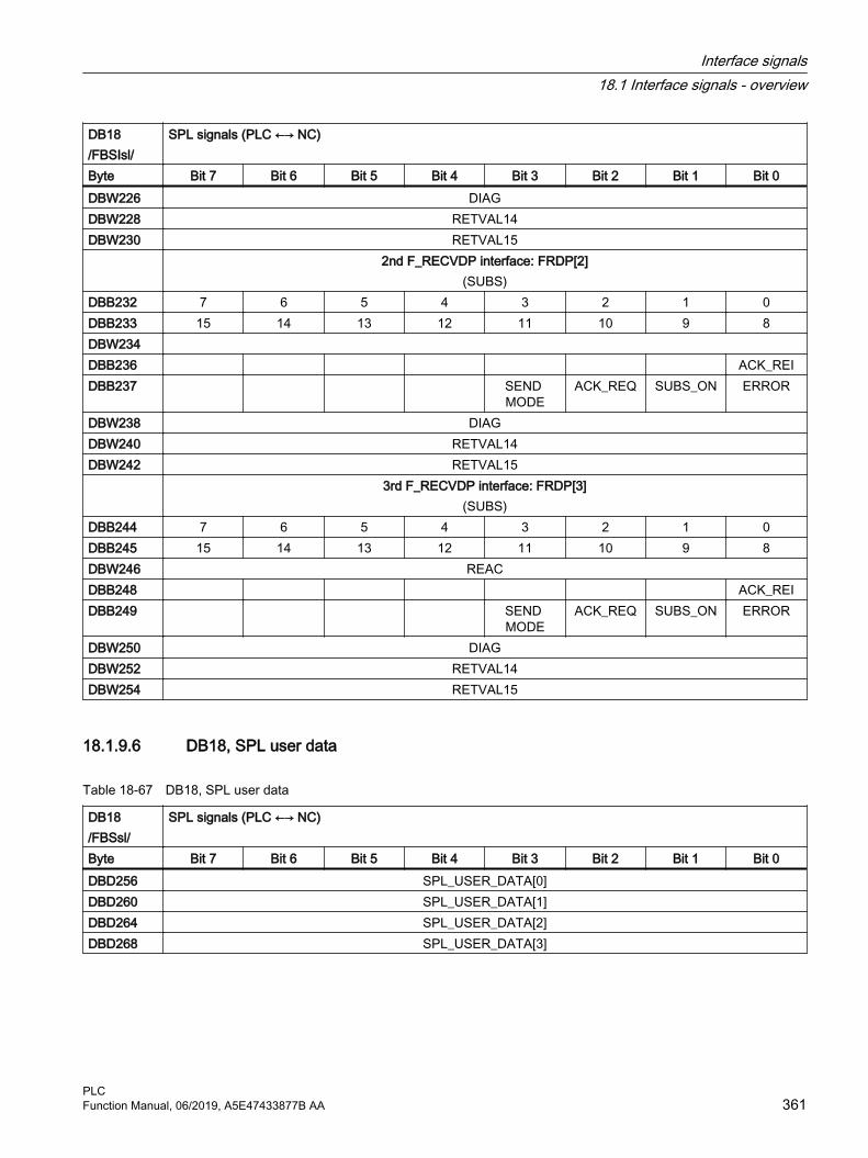
DB18/FBSIsl/
SPL signals (PLC ←→ NC)
Byte Bit 7 Bit 6 Bit 5 Bit 4 Bit 3 Bit 2 Bit 1 Bit 0DBW226 DIAGDBW228 RETVAL14DBW230 RETVAL15 2nd F_RECVDP interface: FRDP[2]
(SUBS)DBB232 7 6 5 4 3 2 1 0DBB233 15 14 13 12 11 10 9 8DBW234 DBB236 ACK_REIDBB237 SEND
MODEACK_REQ SUBS_ON ERROR
DBW238 DIAGDBW240 RETVAL14DBW242 RETVAL15 3rd F_RECVDP interface: FRDP[3]
(SUBS)DBB244 7 6 5 4 3 2 1 0DBB245 15 14 13 12 11 10 9 8DBW246 REACDBB248 ACK_REIDBB249 SEND
MODEACK_REQ SUBS_ON ERROR
DBW250 DIAGDBW252 RETVAL14DBW254 RETVAL15
18.1.9.6 DB18, SPL user data
Table 18-67 DB18, SPL user data
DB18/FBSsl/
SPL signals (PLC ←→ NC)
Byte Bit 7 Bit 6 Bit 5 Bit 4 Bit 3 Bit 2 Bit 1 Bit 0DBD256 SPL_USER_DATA[0]DBD260 SPL_USER_DATA[1]DBD264 SPL_USER_DATA[2]DBD268 SPL_USER_DATA[3]
Interface signals18.1 Interface signals - overview
PLCFunction Manual, 06/2019, A5E47433877B AA 361

18.1.9.7 DB18, data area / errors: Extended data area
Table 18-68 DB18, data area / errors: Extended data area
DB18/FBSIsl/
Signals for the safety SPL (PLC ←→ NC)
Byte Bit 7 Bit 6 Bit 5 Bit 4 Bit 3 Bit 2 Bit 1 Bit 0 Data area of the SPL inputs/outputsDBD272 SPL_DATA_HF.INSEP [65..96]
DBD276 SPL_DATA_HF.INSEP [97..128]
DBD280 SPL_DATA_HF.INSEP [129..160]
DBD284 SPL_DATA_HF.INSEP [161..192]
DBD288 SPL_DATA_HF.OUTSEP [65..96]
DBD292 SPL_DATA_HF.OUTSEP [97..128]
DBD296 SPL_DATA_HF.OUTSEP [129..160]
DBD300 SPL_DATA_HF.OUTSEP [161..192]
Data area for user SPLDBD304 SPL_DATA_HF.INSIP [65..96]
DBD308 SPL_DATA_HF.INSIP [97..128]
DBD312 SPL_DATA_HF.INSIP [129..160]
DBD316 SPL_DATA_HF.INSIP [161..192]
DBD320 SPL_DATA_HF.OUTSIP [65..96]
DBD324 SPL_DATA_HF.OUTSIP [97..128]
DBD328 SPL_DATA_HF.OUTSIP [129..160]
DBD332 SPL_DATA_HF.OUTSIP [161..192]
DBD336 SPL_DATA_HF. MARKERSIP [65..96]
Interface signals18.1 Interface signals - overview
PLC362 Function Manual, 06/2019, A5E47433877B AA

DB18/FBSIsl/
Signals for the safety SPL (PLC ←→ NC)
Byte Bit 7 Bit 6 Bit 5 Bit 4 Bit 3 Bit 2 Bit 1 Bit 0DBD340 SPL_DATA_HF. MARKERSIP [97..128]
DBD344 SPL_DATA_HF. MARKERSIP [129..160]
DBD348 SPL_DATA_HF. MARKERSIP [161..192]
Difference in signal level NC - PLC for diagnosticsDBD352 SPL_DELTA_HF.INSEP [65..96]
DBD356 SPL_DELTA_HF.INSEP [97..128]
DBD360 SPL_DELTA_HF.INSEP [129..160]
DBD364 SPL_DELTA_HF.INSEP [161..192]
DBD368 SPL_DELTA_HF.OUTSEP [65..96]
DBD372 SPL_DELTA_HF.OUTSEP [97..128]
DBD376 SPL_DELTA_HF.OUTSEP [129..160]
DBD380 SPL_DELTA_HF.OUTSEP [161..192]
DBD384 SPL_DELTA_HF. INSIP [65..96]
DBD388 SPL_DELTA_HF.INSIP [97..128]
DBD392 SPL_DELTA_HF.INSIP [129..160]
DBD396 SPL_DATA_HF.INSIP [161..192]
DBD400 SPL_DELTA_HF.OUTSIP [65..96]
DBD404 SPL_DELTA_HF.OUTSIP [97..128]
DBD408 SPL_DELTA_HF.OUTSIP [129..160]
DBD412 SPL_DELTA_HF.OUTSIP [161..192]
DBD416 SPL_DELTA_HF.MARKERSIP [65..96]
Interface signals18.1 Interface signals - overview
PLCFunction Manual, 06/2019, A5E47433877B AA 363

DB18/FBSIsl/
Signals for the safety SPL (PLC ←→ NC)
Byte Bit 7 Bit 6 Bit 5 Bit 4 Bit 3 Bit 2 Bit 1 Bit 0DBD420 SPL_DELTA_HF. MARKERSIP [97..128]
DBD424 SPL_DELTA_HF. MARKERSIP [129..160]
DBD428 SPL_DELTA_HF. MARKERSIP [161..192]
18.1.9.8 DB18, additional data areas: Extended data area
Table 18-69 DB18, additional data areas: Extended data area
DB18/FBSIsl/
Signals for the safety SPL (PLC ←→ NC)
Byte Bit 7 Bit 6 Bit 5 Bit 4 Bit 3 Bit 2 Bit 1 Bit 0 Data area of the single-channel inputs/outputsDBB432von NC
PLCSIOUT_HF [33..40]
DBB433von NC
PLCSIOUT_HF [41..48]
DBB434von NC
PLCSIOUT_HF [49..56]
DBB435von NC
PLCSIOUT_HF [57..64]
DBB436von NC
PLCSIOUT_HF [65..72]
DBB437von NC
PLCSIOUT_HF [73..80]
DBB438von NC
PLCSIOUT_HF [81..88]
DBB439von NC
PLCSIOUT_HF [89..96]
DBB440an NC
PLCSIIN_HF [33..40]
DBB441an NC
PLCSIIN_HF [41..48]
DBB442an NC
PLCSIIN_HF [49..56]
DBB443an NC
PLCSIIN_HF [57..64]
Interface signals18.1 Interface signals - overview
PLC364 Function Manual, 06/2019, A5E47433877B AA
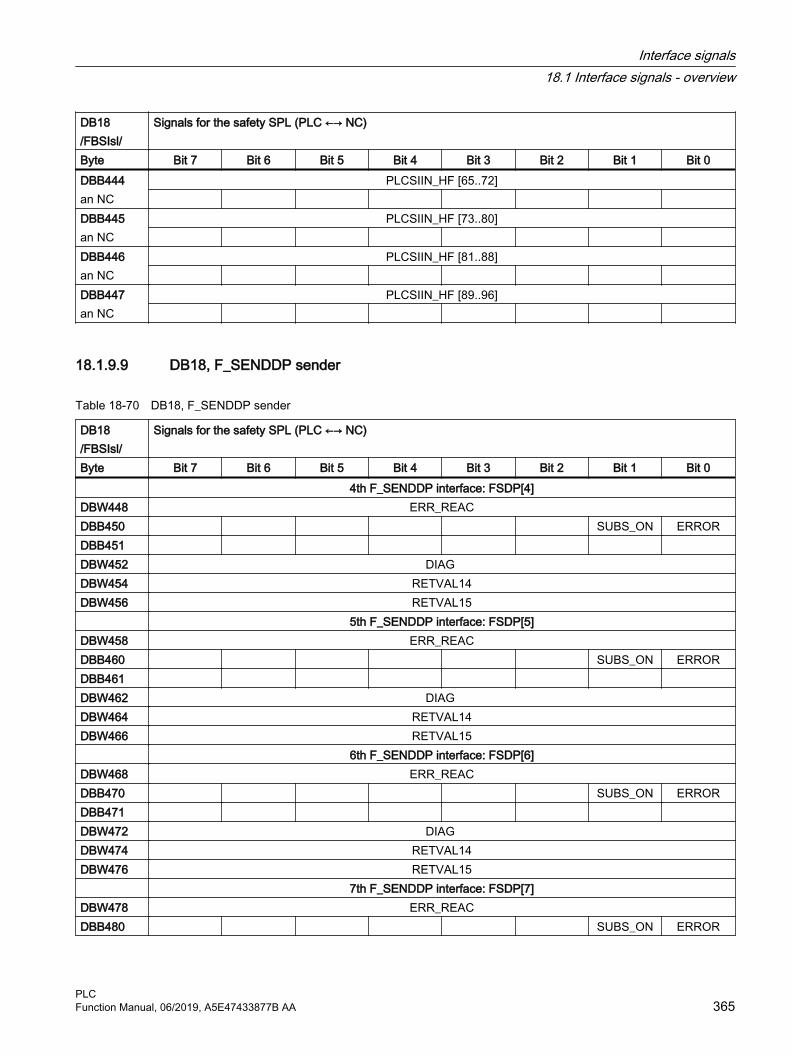
DB18/FBSIsl/
Signals for the safety SPL (PLC ←→ NC)
Byte Bit 7 Bit 6 Bit 5 Bit 4 Bit 3 Bit 2 Bit 1 Bit 0DBB444an NC
PLCSIIN_HF [65..72]
DBB445an NC
PLCSIIN_HF [73..80]
DBB446an NC
PLCSIIN_HF [81..88]
DBB447an NC
PLCSIIN_HF [89..96]
18.1.9.9 DB18, F_SENDDP sender
Table 18-70 DB18, F_SENDDP sender
DB18/FBSIsl/
Signals for the safety SPL (PLC ←→ NC)
Byte Bit 7 Bit 6 Bit 5 Bit 4 Bit 3 Bit 2 Bit 1 Bit 0 4th F_SENDDP interface: FSDP[4]DBW448 ERR_REACDBB450 SUBS_ON ERRORDBB451 DBW452 DIAG DBW454 RETVAL14DBW456 RETVAL15 5th F_SENDDP interface: FSDP[5]DBW458 ERR_REACDBB460 SUBS_ON ERRORDBB461 DBW462 DIAG DBW464 RETVAL14DBW466 RETVAL15 6th F_SENDDP interface: FSDP[6]DBW468 ERR_REACDBB470 SUBS_ON ERRORDBB471 DBW472 DIAG DBW474 RETVAL14DBW476 RETVAL15 7th F_SENDDP interface: FSDP[7]DBW478 ERR_REACDBB480 SUBS_ON ERROR
Interface signals18.1 Interface signals - overview
PLCFunction Manual, 06/2019, A5E47433877B AA 365

DB18/FBSIsl/
Signals for the safety SPL (PLC ←→ NC)
Byte Bit 7 Bit 6 Bit 5 Bit 4 Bit 3 Bit 2 Bit 1 Bit 0DBB481 DBW482 DIAG DBW484 RETVAL14DBW486 RETVAL15 8th F_SENDDP interface: FSDP[8]DBW488 ERR_REACDBB490 SUBS_ON ERRORDBB491 DBW492 DIAG DBW494 RETVAL14DBW496 RETVAL15 9th F_SENDDP interface: FSDP[9]DBW498 ERR_REACDBB500 SUBS_ON ERRORDBB501 DBW502 DIAG DBW504 RETVAL14DBW506 RETVAL15 10th F_SENDDP interface: FSDP[10]DBW508 ERR_REACDBB510 SUBS_ON ERRORDBB511 DBW512 DIAG DBW514 RETVAL14DBW516 RETVAL15 11th F_SENDDP interface: FSDP[11]DBW518 ERR_REACDBB520 SUBS_ON ERRORDBB521 DBW522 DIAG DBW524 RETVAL14DBW526 RETVAL15 12th F_SENDDP interface: FSDP[12]DBW528 ERR_REACDBB530 SUBS_ON ERRORDBB531 DBW532 DIAG DBW534 RETVAL14DBW536 RETVAL15 13th F_SENDDP interface: FSDP[13]DBW538 ERR_REAC
Interface signals18.1 Interface signals - overview
PLC366 Function Manual, 06/2019, A5E47433877B AA

DB18/FBSIsl/
Signals for the safety SPL (PLC ←→ NC)
Byte Bit 7 Bit 6 Bit 5 Bit 4 Bit 3 Bit 2 Bit 1 Bit 0DBB540 SUBS_ON ERRORDBB541 DBW542 DIAG DBW544 RETVAL14DBW546 RETVAL15 14th F_SENDDP interface: FSDP[14]DBW548 ERR_REACDBB550 SUBS_ON ERRORDBB551 DBW552 DIAG DBW554 RETVAL14DBW556 RETVAL15 15th F_SENDDP interface: FSDP[15]DBW558 ERR_REACDBB560 SUBS_ON ERRORDBB561 DBW562 DIAG DBW564 RETVAL14DBW566 RETVAL15 16th F_SENDDP interface: FSDP[16]DBW568 ERR_REACDBB570 SUBS_ON ERRORDBB571 DBW572 DIAG DBW574 RETVAL14DBW576 RETVAL15
18.1.9.10 DB18, F_RECDP receiver
Table 18-71 DB18, F_SENDDP receiver
DB18/FBSIsl/
Signals for the safety SPL (PLC ←→ NC)
Byte Bit 7 Bit 6 Bit 5 Bit 4 Bit 3 Bit 2 Bit 1 Bit 0 4th F_RECVDP interface: FRDP_HF[4] DBB578
(SUBS)7 6 5 4 3 2 1 0
DBB579 15 14 13 12 11 10 9 8DBW580 ERR_REAC DBB582 ACK_REI
Interface signals18.1 Interface signals - overview
PLCFunction Manual, 06/2019, A5E47433877B AA 367

DB18/FBSIsl/
Signals for the safety SPL (PLC ←→ NC)
Byte Bit 7 Bit 6 Bit 5 Bit 4 Bit 3 Bit 2 Bit 1 Bit 0DBB583 SEND‐
MODEACK_REQ SUBS_ON ERROR
DBW584 DIAG DBW586 RETVAL14DBW588 RETVAL15 5th F_RECVDP interface: FRDP_HF[5] DBB590
(SUBS)7 6 5 4 3 2 1 0
DBB591 15 14 13 12 11 10 9 8DBW592 ERR_REACDBB594 ACK_REIDBB595 SEND‐
MODEACK_REQ SUBS_ON ERROR
DBW596 DIAG DBW598 RETVAL14DBW600 RETVAL15 6th F_RECVDP interface: FRDP_HF[6] DBB602
(SUBS)7 6 5 4 3 2 1 0
DBB603 15 14 13 12 11 10 9 8DBW604 ERR_REAC DBB606 ACK_REIDBB607 SEND‐
MODEACK_REQ SUBS_ON ERROR
DBW608 DIAG DBW610 RETVAL14DBW612 RETVAL15 7th F_RECVDP interface: FRDP_HF[7] DBB614
(SUBS)7 6 5 4 3 2 1 0
DBB615 15 14 13 12 11 10 9 8DBW616 ERR_REACDBB618 ACK_REIDBB619 SEND‐
MODEACK_REQ SUBS_ON ERROR
DBW620 DIAG DBW622 RETVAL14DBW624 RETVAL15 8th F_RECVDP interface: FRDP_HF[8] DBB626
(SUBS)7 6 5 4 3 2 1 0
DBB627 15 14 13 12 11 10 9 8
Interface signals18.1 Interface signals - overview
PLC368 Function Manual, 06/2019, A5E47433877B AA

DB18/FBSIsl/
Signals for the safety SPL (PLC ←→ NC)
Byte Bit 7 Bit 6 Bit 5 Bit 4 Bit 3 Bit 2 Bit 1 Bit 0DBW628 ERR_REACDBB630 ACK_REIDBB631 SEND‐
MODEACK_REQ SUBS_ON ERROR
DBW632 DIAG DBW634 RETVAL14DBW636 RETVAL15 9th F_RECVDP interface: FRDP_HF[9] DBB638
(SUBS)7 6 5 4 3 2 1 0
DBB639 15 14 13 12 11 10 9 8DBW640 ERR_REAC DBB642 ACK_REIDBB643 SEND‐
MODEACK_REQ SUBS_ON ERROR
DBW644 DIAG DBW646 RETVAL14DBW648 RETVAL15 10th F_RECVDP interface: FRDP_HF[10] DBB650
(SUBS)7 6 5 4 3 2 1 0
DBB651 15 14 13 12 11 10 9 8DBW652 ERR_REACDBB654 ACK_REIDBB655 SEND‐
MODEACK_REQ SUBS_ON ERROR
DBW656 DIAG DBW658 RETVAL14DBW660 RETVAL15 11th F_RECVDP interface: FRDP_HF[11] DBB662
(SUBS)7 6 5 4 3 2 1 0
DBB663 15 14 13 12 11 10 9 8DBW664 ERR_REAC DBB666 ACK_REIDBB667 SEND‐
MODEACK_REQ SUBS_ON ERROR
DBW668 DIAG DBW670 RETVAL14DBW672 RETVAL15
Interface signals18.1 Interface signals - overview
PLCFunction Manual, 06/2019, A5E47433877B AA 369

DB18/FBSIsl/
Signals for the safety SPL (PLC ←→ NC)
Byte Bit 7 Bit 6 Bit 5 Bit 4 Bit 3 Bit 2 Bit 1 Bit 0 12th F_RECVDP interface: FRDP_HF[12] DBB674
(SUBS)7 6 5 4 3 2 1 0
DBB675 15 14 13 12 11 10 9 8DBW676 ERR_REACDBB678 ACK_REIDBB679 SEND‐
MODEACK_REQ SUBS_ON ERROR
DBW680 DIAG DBW682 RETVAL14DBW684 RETVAL15 13th F_RECVDP interface: FRDP_HF[13] DBB686
(SUBS)7 6 5 4 3 2 1 0
DBB687 15 14 13 12 11 10 9 8DBW688 ERR_REACDBB690 ACK_REIDBB691 SEND‐
MODEACK_REQ SUBS_ON ERROR
DBW692 DIAG DBW694 RETVAL14DBW696 RETVAL15 14th F_RECVDP interface: FRDP_HF[14] DBB698
(SUBS)7 6 5 4 3 2 1 0
DBB699 15 14 13 12 11 10 9 8DBW700 ERR_REAC DBB702 ACK_REIDBB703 SEND‐
MODEACK_REQ SUBS_ON ERROR
DBW704 DIAG DBW706 RETVAL14DBW708 RETVAL15 15th F_RECVDP interface: FRDP_HF[15] DBB710
(SUBS)7 6 5 4 3 2 1 0
DBB711 15 14 13 12 11 10 9 8DBW712 ERR_REACDBB714 ACK_REIDBB715 SEND‐
MODEACK_REQ SUBS_ON ERROR
Interface signals18.1 Interface signals - overview
PLC370 Function Manual, 06/2019, A5E47433877B AA
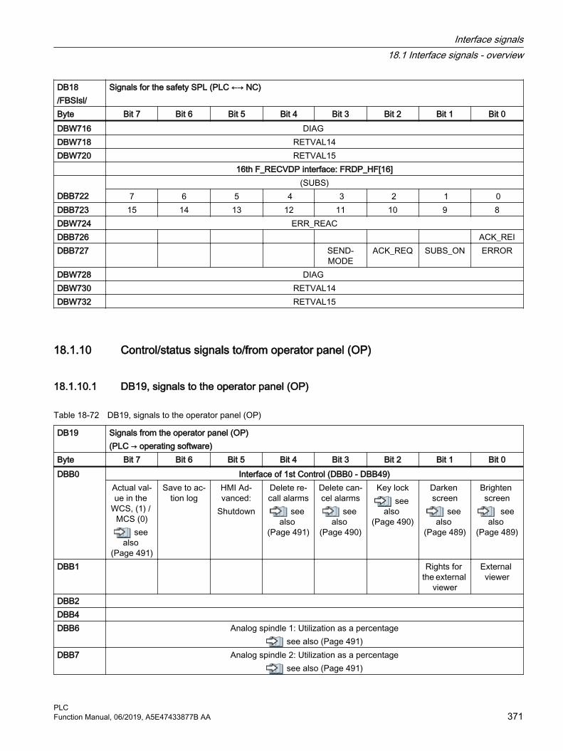
DB18/FBSIsl/
Signals for the safety SPL (PLC ←→ NC)
Byte Bit 7 Bit 6 Bit 5 Bit 4 Bit 3 Bit 2 Bit 1 Bit 0DBW716 DIAG DBW718 RETVAL14DBW720 RETVAL15 16th F_RECVDP interface: FRDP_HF[16] DBB722
(SUBS)7 6 5 4 3 2 1 0
DBB723 15 14 13 12 11 10 9 8DBW724 ERR_REACDBB726 ACK_REIDBB727 SEND‐
MODEACK_REQ SUBS_ON ERROR
DBW728 DIAG DBW730 RETVAL14DBW732 RETVAL15
18.1.10 Control/status signals to/from operator panel (OP)
18.1.10.1 DB19, signals to the operator panel (OP)
Table 18-72 DB19, signals to the operator panel (OP)
DB19 Signals from the operator panel (OP)(PLC → operating software)
Byte Bit 7 Bit 6 Bit 5 Bit 4 Bit 3 Bit 2 Bit 1 Bit 0DBB0 Interface of 1st Control (DBB0 - DBB49)
Actual val‐ue in the
WCS, (1) / MCS (0)
see also
(Page 491)
Save to ac‐tion log
HMI Ad‐vanced:
Shutdown
Delete re‐call alarms
see also
(Page 491)
Delete can‐cel alarms
see also
(Page 490)
Key locksee
also (Page 490)
Darken screen
see also
(Page 489)
Brighten screen
see also
(Page 489)
DBB1 Rights for the external
viewer
External viewer
DBB2 DBB4 DBB6 Analog spindle 1: Utilization as a percentage
see also (Page 491)DBB7 Analog spindle 2: Utilization as a percentage
see also (Page 491)
Interface signals18.1 Interface signals - overview
PLCFunction Manual, 06/2019, A5E47433877B AA 371
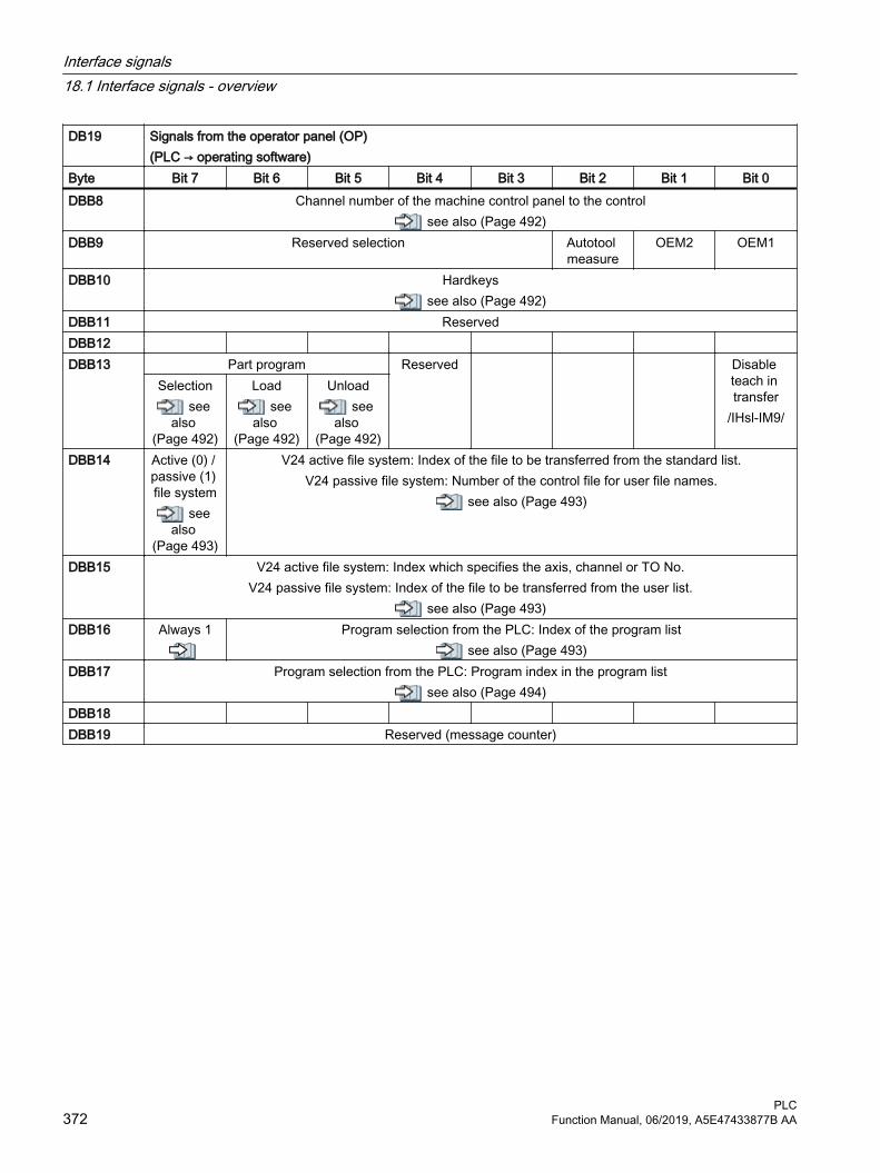
DB19 Signals from the operator panel (OP)(PLC → operating software)
Byte Bit 7 Bit 6 Bit 5 Bit 4 Bit 3 Bit 2 Bit 1 Bit 0DBB8 Channel number of the machine control panel to the control
see also (Page 492)DBB9 Reserved selection Autotool
measureOEM2 OEM1
DBB10 Hardkeyssee also (Page 492)
DBB11 ReservedDBB12 DBB13 Part program Reserved Disable
teach in transfer
/IHsl-IM9/
Selectionsee
also (Page 492)
Loadsee
also (Page 492)
Unloadsee
also (Page 492)
DBB14 Active (0) / passive (1) file system
see also
(Page 493)
V24 active file system: Index of the file to be transferred from the standard list.V24 passive file system: Number of the control file for user file names.
see also (Page 493)
DBB15 V24 active file system: Index which specifies the axis, channel or TO No.V24 passive file system: Index of the file to be transferred from the user list.
see also (Page 493)DBB16 Always 1 Program selection from the PLC: Index of the program list
see also (Page 493)DBB17 Program selection from the PLC: Program index in the program list
see also (Page 494)DBB18 DBB19 Reserved (message counter)
Interface signals18.1 Interface signals - overview
PLC372 Function Manual, 06/2019, A5E47433877B AA

18.1.10.2 DB19, signals from the operator panel (OP)
Table 18-73 DB19, signals from the operator panel (OP)
DB19 Signals from the operator panel (OP)(Operating software → PLC)
Byte Bit 7 Bit 6 Bit 5 Bit 4 Bit 3 Bit 2 Bit 1 Bit 0DBB20 Switch over
MCS/WCSsee al‐
so (Page 496)
Simulation active
see also
(Page 496)
Language 2 switched
over/IHsl-IM9/
Recall alarm de‐
letedsee
also (Page 495)
Cancel alarm de‐
letedsee
also (Page 495)
Cancel key actuated/FB-A2/
Screen is dark
see also
(Page 495)
DBB21 Current number of the active operating range/FB-P3/; /FB-A2/
DBB22 Current channel numbersee also (Page 496)
DBB23 Control 1Screen
change ac‐tive
Data trans‐fer active
Keyboard has been
usedDBW24 Current screen number
see also (Page 496)DBB25 DBB26 Program selection from the PLC: Status signals
Selectionsee al‐
so (Page 499)
Loadsee
also (Page 498)
Unloadsee
also (Page 498)
Activesee
also (Page 497)
Errorsee
also (Page 497)
Job com‐pleted
see also
(Page 497)
Reserved
DBB27 Program selection from the PLC: Error codesee also (Page 499)
DBW28 Screen number for "Supplement user interface" /IHsl-BE2/ DBB30PLC → OP
Screen selection from the PLC: Control signals Screen de‐
selectionScreen se‐
lectionDBB31Operating software → PLC
Screen selection from the PLC: Status signalsInactive Error,
screen se‐lection not
possible
Screen is deselected
Screen ac‐tive
Screen is selected
Screen se‐lection ac‐
cepted
DBB32PLC → op‐erating soft‐ware
Busy func‐tionsee al‐
so (Page 501)
Strobe function
see also
(Page 501)
Function selection No. from the PLCsee also (Page 500)
Interface signals18.1 Interface signals - overview
PLCFunction Manual, 06/2019, A5E47433877B AA 373

DB19 Signals from the operator panel (OP)(Operating software → PLC)
Byte Bit 7 Bit 6 Bit 5 Bit 4 Bit 3 Bit 2 Bit 1 Bit 0DBB33PLC → op‐erating soft‐ware
Parameter 1 for function selection No. (function selection from DBB32)see also (Page 501)
DBB34PLC → op‐erating soft‐ware
Parameter 2 for function selection No. (function selection from DBB32)
DBB35PLC → op‐erating soft‐ware
Parameter 3 for function selection No. (function selection from DBB32)
DBB36Operating software → PLC
Error code for function selection No. (function selection from DBB32)see also (Page 502)
DBB37Operating software → PLC
Parameter 1 for function selection No. (function selection from DBB48)
DBB38Operating software → PLC
Parameter 2 for function selection No. (function selection from DBB48)
DBB39Operating software → PLC
Parameter 3 for function selection No. (function selection from DBB48)
DBB40 - DBB47
Reserved
DBB48Operating software → PLC
PLC busyFunction
Operating software
strobeFunction
Function selection No. from the operating software
DBB49PLC → op‐erating soft‐ware
Error code for function selection No. (function selection from DBB48)
DBB50 - DBB99
Interface of 2nd Control (assignment the same as DBB0 - DBB49)
DBB100 Switchover interface to the operating softwareCall waiting interface (operating software announces itself to the NC)
ONL_REQUEST (online request from operating software) /FB-B3/Operating software writes its client identification as online request (bits 8-15: bus type, bits 0-7: bus address)
Interface signals18.1 Interface signals - overview
PLC374 Function Manual, 06/2019, A5E47433877B AA

DB19 Signals from the operator panel (OP)(Operating software → PLC)
Byte Bit 7 Bit 6 Bit 5 Bit 4 Bit 3 Bit 2 Bit 1 Bit 0DBB102 ONL_CONFIRM (acknowledgment from PLC after online request) /FB-B3/
PLC writes as acknowledgment the operating software client identification (bus type, bus address; such as DBB100)
DBB104 PAR_CLIENT_IDENT /FB-B3/Operating software writes its client identification (bus type, bus address; such as DBB100).
DBB106 PAR_MMC_TYP /FB-B3/Type of operating software acc. to NETNAMES.INI: Main/secondary operator panel / server /...
DBB107 PAR_MCP_ADR /FB-B3/Operating software writes address of the MCP to be activated; 255, if no MCP activation
DBB108 PAR_STATUS /FB-B3/PLC writes the online enable for the operating software
DBB109 PAR_Z_INFO /FB-B3/ PLC writes additional info on the status
DBB110 M_TO_N_ALIVESign-of-life from the PLC to the operating software using the M to N block
DBB112 Res. Bus type MCPDBB113 ParOpKeyAdr
Direct key index call waiting interfaceDBB114 ParTcuIndex
TCU index call waiting interfaceDBB115 ParHt2Index
Ht2 index logon interfaceDBB116 Direct key address of 1st Online interfaceDBB117 Direct key address of 2nd Online interfaceDBB118 TCU index of 1st Online interfaceDBB119 TCU index of 2nd Online interfaceDBB120 Online interface OP 1 (user)
MMC1_CLIENT_IDENT /FB-B3/PLC writes PAR_CLIENT_IDENT to MMCx_CLIENT_IDENT, if operating software goes online.
DBB122 MMC1_TYP /FB-B3/PLC writes PAR_MMC_TYP to MMCx_TYP, if operating software goes online.
DBB123 MMC1_MCP_ADR /FB-B3/PLC writes PAR_MCP_ADR to MMCx_MCP_ADR, if operating software goes online.
DBB124 MMC1_STATUS /FB-B3/Connection state, operating software and PLC write alternating their requests/acknowledgments.
DBB125 MMC1_Z_INFO /FB-B3/Additional information, connection state (pos./neg. acknowledgment, error messages, etc.)
DBB126 Reserved TCU1_SHIFT_LOCK
MMC1_CHANGE_DENIED/FB-B3/
MMC1_ACTIVE_
CHANGED/FB2B3/
MMC1_ACTIVE_
PERM/FB-B3/
MMC1_ACTIVE_
REQ/FB-B3/
MMC1_MCP_SHIFT-LOCK
/FB-B3/
MMC1_SHIFT_LOCK
/FB-B3/
Interface signals18.1 Interface signals - overview
PLCFunction Manual, 06/2019, A5E47433877B AA 375

DB19 Signals from the operator panel (OP)(Operating software → PLC)
Byte Bit 7 Bit 6 Bit 5 Bit 4 Bit 3 Bit 2 Bit 1 Bit 0DBB127 Reserved bus type MCP
DBB128 - DBB129
Reserved Transline (Transline DB number)
DBB130 Online interface OP 2 (user)MMC2_CLIENT_IDENT /FB-B3/
PLC writes PAR_CLIENT_IDENT to MMCx_CLIENT_IDENT, if operating software goes online.DBB132 MMC2_TYP /FB-B3/
PLC writes PAR_MMC_TYP to MMCx_TYP, if operating software goes online.DBB133 MMC2_MCP_ADR /FB-B3/
PLC writes PAR_MCP_ADR to MMCx_MCP_ADR, if operating software goes online.DBB134 MMC2_STATUS /FB-B3/
Connection state, operating software and PLC write alternating their requests/acknowledgments.DBB135 MMC2_Z_INFO /FB-B3/
Additional information, connection state (pos./neg. acknowledgment, error messages, etc.)DBB136 Reserved TCU2_
SHIFT_LOCK
MMC2_CHANGE_DENIED/FB-B3/
MMC2_ACTIVE_
CHANGED/FB-B3/
MMC2_ACTIVE_
PERM/FB-B3/
MMC2_ACTIVE_
REQ/FB-B3/
MMC2_MCP_
SHIFT_LOCK
/FB-B3/
MMC2_SHIFT_LOCK
/FB-B3/
DBB137 Reserved bus type MCP
DBB138 - DBB139
Reserved Transline (Transline DB number)
DBB140 - DBB197
Assignment of the PLC for transfer parametersThese data blocks are reserved for the "Tool Ident Connection" option.
/FBWsl/DBB198 - DBB249
Assignment of the PLC for return valuesThese data blocks are reserved for the "Tool Ident Connection" option.
/FBWsl/DBB250 - DBB255
Function call of the PLC interfaceThese data blocks are reserved for the "Tool Ident Connection" option.
/FBWsl/DBB256 - DBB267
Commands for Paramtm.exe
DBB268 Traffic light statusDBD270 - DBD394
Counter [1...32]
DBB398 Handwheel number for simulation overrideDBW400 Simulation overrideDBW402 Simulation state
Interface signals18.1 Interface signals - overview
PLC376 Function Manual, 06/2019, A5E47433877B AA

18.1.10.3 DB19, sidescreen - interface for the MCP function
Table 18-74 DB19, sidescreen - interface for the MCP function
DB19 Signals to/from the operator panelSignal from the operating software → PLC
Byte Bit 7 Bit 6 Bit 5 Bit 4 Bit 3 Bit 2 Bit 1 Bit 0DBB404 Customer keys
8 7 6 5 4 3 2 1DBB405 Customer keys
16 15 14 13 12 11 10 9DBB406
Customer keys
24 23 22 21 20 19 18 17DBB407
Customer keys
32 31 30 29 28 27 26 25DBB408
Customer keys
40 39 38 37 36 35 34 33DBB409
Customer keys
48 47 46 45 44 43 42 41DBB410
Customer keys
56 55 54 53 52 51 50 49DBB411 Customer keys
64 63 62 61 60 59 58 57
18.1.10.4 DB19, sidescreen - interface for the MCP function
Table 18-75 DB19, sidescreen - interface for the MCP function signals to/from the operator panel
DB19 Signals to/from the operator panel [r/w]Signal from PLC → operating software
Byte Bit 7 Bit 6 Bit 5 Bit 4 Bit 3 Bit 2 Bit 1 Bit 0DBB412 Customer LED
8 7 6 5 4 3 2 1DBB413 Customer LED
16 15 14 13 12 11 10 9DBB414 Customer LED
24 23 22 21 20 19 18 17DBB415 Customer LED
32 31 30 29 28 27 26 25DBB416 Customer LED
40 39 38 37 36 35 34 33DBB417 Customer LED
48 47 46 45 44 43 42 41
Interface signals18.1 Interface signals - overview
PLCFunction Manual, 06/2019, A5E47433877B AA 377

DB19 Signals to/from the operator panel [r/w]Signal from PLC → operating software
Byte Bit 7 Bit 6 Bit 5 Bit 4 Bit 3 Bit 2 Bit 1 Bit 0DBB418 Customer LED
56 55 54 53 52 51 50 49DBB419 Customer LED
64 63 62 61 60 59 58 57DBB420 Customer key deactivated
8 7 6 5 4 3 2 1DBB421 Customer key deactivated
16 15 14 13 12 11 10 9DBB422 Customer key deactivated
24 23 22 21 20 19 18 17DBB423 Customer key deactivated
32 31 30 29 28 27 26 25DBB424 Customer key deactivated
40 39 38 37 36 35 34 33DBB425 Customer key deactivated
48 47 46 45 44 43 42 41DBB426 Customer key deactivated
56 55 54 53 52 51 50 49DBB427 Customer key deactivated
64 63 62 61 60 59 58 57
18.1.11 Defining PLC alarms
18.1.11.1 DB20, NC machine data
Table 18-76 DB20, NC machine data
DB20 NC machine data (PLC → user)Byte Bit 7 Bit 6 Bit 5 Bit 4 Bit 3 Bit 2 Bit 1 Bit 0DBW0 INT values
DBW
DBW INT values
DBB Bit arrays
DBB
Interface signals18.1 Interface signals - overview
PLC378 Function Manual, 06/2019, A5E47433877B AA

DB20 NC machine data (PLC → user)Byte Bit 7 Bit 6 Bit 5 Bit 4 Bit 3 Bit 2 Bit 1 Bit 0DBB
DBB Bit arrays
DBD REAL values
DBD
DBD REAL values
Note
The start and end addresses of the PLC machine data areas are dependent on the particular length data of the partial areas. The range of INTEGER values always starts with data byte 0. The upper limit is defined by the associated length data. The range of the bit arrays starts after the range of the INTEGER values at the next even address. The range of REAL values starts after the range of the bit arrays at the next even address.
18.1.12 Channel-specific signals
18.1.12.1 DB21 - DB30, control signals to the channel (1)
DB21 - DB30
Signals to the channel (PLC → NC)
Byte Bit 7 Bit 6 Bit 5 Bit 4 Bit 3 Bit 2 Bit 1 Bit 0DBB0 Activate dry
run feedrate see
also (Page 504)
Activate M01
see also
(Page 504)
Activate single block
see also
(Page 503)
Activate DRF
see also
(Page 503)
RESU:Start re‐
trace sup‐port
see also
(Page 503)
RESU:Backward/
forwardsee
also (Page 502)
DBB1 Activate program
testsee
also (Page 508)
PLC action completed
see also
(Page 507)
CLC correc‐tion
see also
(Page 507)
CLC stopsee
also (Page 506)
Time moni‐toring ac‐tive (tool manage‐
ment)see
also (Page 506)
Disable all synchron‐
ized actions/FBSY/
Enable pro‐tection zones
/FB-A5/
Activate ref‐erencing
see also
(Page 505)
Interface signals18.1 Interface signals - overview
PLCFunction Manual, 06/2019, A5E47433877B AA 379

DB21 - DB30
Signals to the channel (PLC → NC)
Byte Bit 7 Bit 6 Bit 5 Bit 4 Bit 3 Bit 2 Bit 1 Bit 0DBB2 Activate skip block
see also (Page 509)/7 /6 /5 /4 /3 /2 /1 /0
DBB3 Nibbling and punching Manual
stroke initia‐tion
see also
(Page 512)
Stroke inop‐erative
see also
(Page 511)
Delayed stroke
see also
(Page 511)
Stroke sup‐pression
see also
(Page 511)
Manual stroke initia‐
tionsee
also (Page 510)
Stroke ena‐ble
see also
(Page 510)
DBB4 Path feedrate overridesee also (Page 512)
H G F E D C B ADBB5 Path rapid traverse override
see also (Page 514)H G F E D C B A
DBB6 Path fee‐drate over‐ride active
see also
(Page 519)
Path rapid traverse
override ac‐tive
see also
(Page 519)
Program level abort
see also
(Page 518)
Delete UP number of
passes
Delete dis‐tance-to-go
see also
(Page 518)
Read-in dis‐able
see also
(Page 517)
Feedrate disable
see also
(Page 516)
DBB7 Resetsee
also (Page 522)
Activate configured
STOP
Deactivate start disable
NC Stop ax‐es plus spindle
see also
(Page 522)
NC stopsee
also (Page 521)
NC Stop at block limit
see also
(Page 520)
NC startsee
also (Page 520)
NC start disable
see also
(Page 519)
DBB8 Activate machine-related protection area see also (Page 523)
8 7 6 5 4 3 2 1DBB9 Activate machine-related protection area
see also (Page 523) 10 9
DBB10 Activate channel-specific protection area see also (Page 524)
8 7 6 5 4 3 2 1DBB11 Activate channel-specific protection area
see also (Page 524) 10 9
Interface signals18.1 Interface signals - overview
PLC380 Function Manual, 06/2019, A5E47433877B AA

Note● Feedrate override active: Even if the feedrate override is not active (= 100%), the 0%
position is still effective.● Feedrate override: Either 31 positions (Gray code) with 31 MD for % evaluation, or 0% to
200% corresponding to the dual value in the byte (201 to 255 = max. 200%)● Rapid traverse override: Either 31 positions (Gray code) with 31 MD for % evaluation, or 0%
to 100% corresponding to the dual value in the byte (101 to 255 = max. 100%)● Single block: Select the version using "Write variable"● Delete distance-to-go: Is only active for path axes and not for positioning axes
18.1.12.2 DB21 - DB30, control signals to the geometry axes
Table 18-77 DB21 - DB30, control signals to the geometry axes
DB21 - DB30
Signals to the channel (PLC → NC)
Byte Bit 7 Bit 6 Bit 5 Bit 4 Bit 3 Bit 2 Bit 1 Bit 0 Geometry axis 1DBB12 Traversing keys
see also (Page 527)Rapid tra‐
verse over‐ride
see also
(Page 526)
Traversing key lock
see also
(Page 526)
Feedrate stop
see also
(Page 525)
Activate handwheelsee also (Page 524)
Plus Minus C B A
DBB13 Requested machine functionsee also (Page 529)
Continuous manual travel
INCvar INC10000 INC1000 INC100 INC10 INC1
DBB14 OEM signals
DBB15 Invert hand‐wheel direc‐tion of rota‐
tionsee
also (Page 530)
Geometry axis 2
Interface signals18.1 Interface signals - overview
PLCFunction Manual, 06/2019, A5E47433877B AA 381

DB21 - DB30
Signals to the channel (PLC → NC)
Byte Bit 7 Bit 6 Bit 5 Bit 4 Bit 3 Bit 2 Bit 1 Bit 0DBB16 Traversing keys
see also (Page 531)
Rapid tra‐verse over‐
ridesee
also (Page 531)
Traversing key lock
see also
(Page 531)
Feedrate stop
see also
(Page 525)
Activate handwheelsee also (Page 530)
Plus Minus C B A
DBB17 Requested machine functionsee also (Page 531)
Continuous manual travel
INCvar INC10000 INC1000 INC100 INC10 INC1
DBB18 OEM signals
DBB19 Invert hand‐wheel direc‐tion of rota‐
tionsee
also (Page 531)
Geometry axis 3DBB20 Traversing keys
see also (Page 532)
Rapid tra‐verse over‐
ridesee
also (Page 532)
Traversing key lock
see also
(Page 531)
Feedrate stop
see also
(Page 525)
Activate handwheelsee also (Page 531)
Plus Minus C B A
DBB21 Requested machine functionsee also (Page 532)
Continuous manual travel
INCvar INC10000 INC1000 INC100 INC10 INC1
DBB22 OEM signals
DBB23 Invert hand‐wheel direc‐tion of rota‐
tionsee
also (Page 532)
Interface signals18.1 Interface signals - overview
PLC382 Function Manual, 06/2019, A5E47433877B AA

Note
The NC only evaluates the machine function signals if the signal DB10 DBX57.0 (Page 340)"INC inputs in mode group area active" is not set.
18.1.12.3 DB21 - DB30, HMI signals to channel / OEM signals from/to channel
Table 18-78 DB21 - DB30, control signals from the operating software to the PLC, PLC to the NC and status signal from channel to the PLC
DB21 - DB30
Signals from the channel/PLC/operating software (operating software → PLC, PLC → NC, NC → PLC)
Byte Bit 7 Bit 6 Bit 5 Bit 4 Bit 3 Bit 2 Bit 1 Bit 0DBB24Operating software → PLC
Dry run fee‐drate selec‐
ted see
also (Page 534)
M01 selec‐ted
see also
(Page 533)
M01 associ‐ated with NC selec‐
tedsee
also (Page 533)
DRF selec‐ted
see also
(Page 532)
Activate configured
STOP
DBB25Operating software → PLC
Program test selec‐
ted/FB-K1/
REPOS mode change/FB-K1/
Feedrate override se‐lected for rapid tra‐
versesee
also (Page 534)
REPOS mode /FB-K1/C B A
DBB26Operating software → PLC
Skip block requested, level/x /FB-K1/
/7 /6 /5 /4 /3 /2 /1 /0
DBB27Operating software → PLC
Skip block requested, lev‐el/x
/9 /8
DBB28PLC → NC
OEM signals: Requirement
DBB29PLC → NC
Tooldo not lock
see also
(Page 539)
Deactivate wear moni‐
toringsee
also (Page 539)
Deactivate workpiece
countersee
also (Page 538)
Activate PTP traver‐
salsee
also (Page 538)
Activate fixed feedratesee also (Page 537)
4 3 2 1
Interface signals18.1 Interface signals - overview
PLCFunction Manual, 06/2019, A5E47433877B AA 383

DB21 - DB30
Signals from the channel/PLC/operating software (operating software → PLC, PLC → NC, NC → PLC)
Byte Bit 7 Bit 6 Bit 5 Bit 4 Bit 3 Bit 2 Bit 1 Bit 0DBB30PLC → NC
No tool change
commands
Jog circlessee
also (Page 542)
Activate NC-associ‐ated M0/1
see also
(Page 541)
Contour handwheel simulation, negative di‐
rectionsee
also (Page 541)
Simulation contour
handwheel on
see also
(Page 540)
Activate contour handwheelsee also (Page 540)
C B A
DBB31PLC → NC
Activate skip block Invert con‐tour hand‐
wheel direc‐tion of rota‐
tionsee
also (Page 544)
REPOS mode change
see also
(Page 543)
REPOS modesee also (Page 542)
/9 /8 C B A
DBB32NC → PLC
Last action block active
see also
(Page 546)
M00/M01 active
see also
(Page 545)
Approach block active
see also
(Page 545)
Action block active
see also
(Page 545)
RESU:Retrace
support ac‐tive
see also
(Page 544)
RESU:Retrace
mode activesee
also (Page 544)
Execution from exter‐nal active
DBB33NC → PLC
Program test active
see also
(Page 549)
Transfor‐mation ac‐
tivesee
also (Page 549)
M02/M30 active
see also
(Page 547)
Block search ac‐
tivesee
also (Page 547)
Handwheel override ac‐
tivesee
also (Page 547)
Rotational feedrate ac‐
tive/FB-V1/
Orientable toolholder
active
Referenc‐ing active
see also
(Page 546)
DBB34NC → PLC
OEM signals: Feedback signal
DBB35NC → PLC
Channel state Program statusReset
see also
(Page 554)
Interruptedsee
also (Page 554)
Activesee
also (Page 553)
interruptedsee
also (Page 552)
Interruptedsee
also (Page 552)
Stoppedsee
also (Page 551)
Waitingsee
also (Page 550)
Runningsee
also (Page 550)
DBB36NC → PLC
NC alarm with ma‐chining
stop is ac‐tive
see also
(Page 557)
Channel-specific NC alarm is ac‐
tivesee
also (Page 556)
Channel is ready
see also
(Page 556)
Interrupt handling
activesee
also (Page 556)
All axes sta‐tionary
see also
(Page 555)
All axes that have to
be refer‐enced are referenced
see also
(Page 555)
Interface signals18.1 Interface signals - overview
PLC384 Function Manual, 06/2019, A5E47433877B AA

DB21 - DB30
Signals from the channel/PLC/operating software (operating software → PLC, PLC → NC, NC → PLC)
Byte Bit 7 Bit 6 Bit 5 Bit 4 Bit 3 Bit 2 Bit 1 Bit 0DBB37NC → PLC
"Stop at the end of
block for single block
(SBL)" is suppressed
see also
(Page 560)
Read-in dis‐able is ig‐
noredsee
also (Page 559)
CLC stop‐ped
Upper limitsee
also (Page 558)
CLC stop‐ped
Lower limitsee
also (Page 558)
CLC activesee
also (Page 558)
Contour handwheel active see also (Page 557)
C B A
DBB38NC → PLC
Nibbling and punching /FB-N4/ Manual
stroke initia‐tion: Ac‐
knowledg‐ment
see also
(Page 560)
Stroke re‐lease active
see also
(Page 560)
DBB39NC → PLC
Stop at end of block
due to con‐figured stop
Configured stop is acti‐
vated
Contour handwheel direction of rotation in‐verted ac‐
tivesee
also (Page 561)
Stop at end of block
due to sin‐gle block
NC alarm with pro‐
gram stopsee
also (Page 561)
Protection area moni‐toring not
guaranteed/FB-A5/
18.1.12.4 DB21 - DB30, control signals from the geometry axes
Table 18-79 DB21 - DB30, control signals from the geometry axes
DB21 - DB30
Signals from the channel (NC → PLC)
Byte Bit 7 Bit 6 Bit 5 Bit 4 Bit 3 Bit 2 Bit 1 Bit 0 Geometry axis 1DBB40 Travel command
see also (Page 563)Traversing requests
see also (Page 563) Handwheel active
see also (Page 562)Plus Minus Plus Minus C B A
DBB41 Active machine function see also (Page 564)
Continuous manual travel
INCvar INC10000 INC1000 INC100 INC10 INC1
DBB42 OEM signals
Interface signals18.1 Interface signals - overview
PLCFunction Manual, 06/2019, A5E47433877B AA 385

DB21 - DB30
Signals from the channel (NC → PLC)
Byte Bit 7 Bit 6 Bit 5 Bit 4 Bit 3 Bit 2 Bit 1 Bit 0DBB43 Handwheel
direction of rotation in‐
vertedsee
also (Page 564)
DBB44Operating soft‐ware → PLC
Geometry axis 2DBB46 Travel command
see also (Page 565)Traversing requests
see also (Page 565) Handwheel active
see also (Page 565)Plus Minus Plus Minus C B A
DBB47 Active machine functionsee also (Page 565)
Continuous manual travel
INCvar INC10000 INC1000 INC100 INC10 INC1
DBB48 OEM signals
DBB49 Handwheel direction of rotation in‐
vertedsee
also (Page 565)
DBB50Operating soft‐ware → PLC
Geometry axis 3DBB52 Travel command
see also (Page 566)Traversing requests
see also (Page 566) Handwheel active
see also (Page 566) C B A
DBB53 Active machine functionsee also (Page 566)
Continuous manual travel
INCvar INC10000 INC1000 INC100 INC10 INC1
DBB54 OEM signals
Interface signals18.1 Interface signals - overview
PLC386 Function Manual, 06/2019, A5E47433877B AA

DB21 - DB30
Signals from the channel (NC → PLC)
Byte Bit 7 Bit 6 Bit 5 Bit 4 Bit 3 Bit 2 Bit 1 Bit 0DBB55 Handwheel
direction of rotation in‐
vertedsee
also (Page 566)
DBB56Operating soft‐ware → PLC
18.1.12.5 DB21 - DB30, change signals for auxiliary function transfer from the channel
Table 18-80 DB21 - DB30, change signals for auxiliary function transfer from the channel
DB21 - DB30
Signals from the channel (NC → PLC)
Byte Bit 7 Bit 6 Bit 5 Bit 4 Bit 3 Bit 2 Bit 1 Bit 0DBB58 change
see also (Page 566)M fct. 5 M fct. 4 M fct. 3 M fct. 2 M fct. 1
DBB59 Not decoded see also (Page 567)
M fct. 5 M fct. 4 M fct. 3 M fct. 2 M fct. 1DBB60 Quick
see also (Page 567) change
see also (Page 566)S fct. 3 S fct. 2 S fct. 1 S fct. 3 S fct. 2 S fct. 1
DBB61 Quicksee also (Page 567)
changesee also (Page 566)
T fct. 3 T fct. 2 T fct. 1 T fct. 3 T fct. 2 T fct. 1DBB62 Quick
see also (Page 567) change
see also (Page 566)D fct. 3 D fct. 2 D fct. 1 D fct. 3 D fct. 2 D fct. 1
DBB63 DL fct. Quick
DL fct.change
DBB64 Quicksee also (Page 567)
changesee also (Page 566)
H fct. 3 H fct. 2 H fct. 1 H fct. 3 H fct. 2 H fct. 1DBB65 change
see also (Page 566)F fct. 6 F fct. 5 F fct. 4 F fct. 3 F fct. 2 F fct. 1
Interface signals18.1 Interface signals - overview
PLCFunction Manual, 06/2019, A5E47433877B AA 387
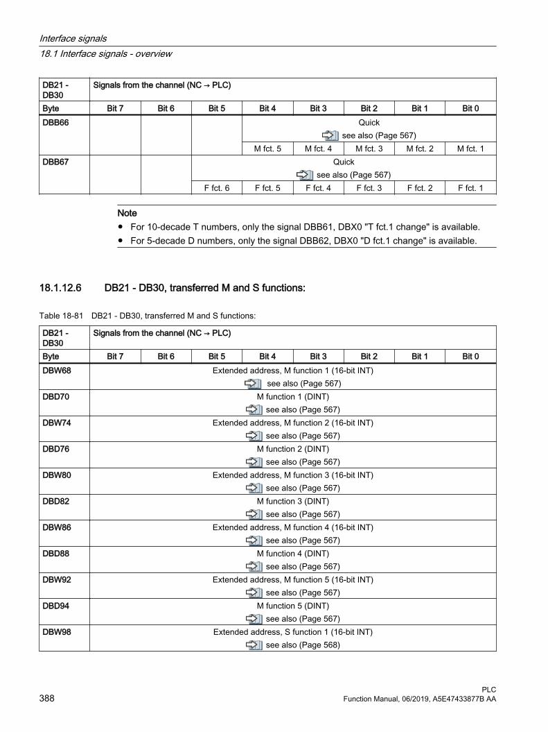
DB21 - DB30
Signals from the channel (NC → PLC)
Byte Bit 7 Bit 6 Bit 5 Bit 4 Bit 3 Bit 2 Bit 1 Bit 0DBB66 Quick
see also (Page 567)M fct. 5 M fct. 4 M fct. 3 M fct. 2 M fct. 1
DBB67 Quicksee also (Page 567)
F fct. 6 F fct. 5 F fct. 4 F fct. 3 F fct. 2 F fct. 1
Note● For 10-decade T numbers, only the signal DBB61, DBX0 "T fct.1 change" is available.● For 5-decade D numbers, only the signal DBB62, DBX0 "D fct.1 change" is available.
18.1.12.6 DB21 - DB30, transferred M and S functions:
Table 18-81 DB21 - DB30, transferred M and S functions:
DB21 - DB30
Signals from the channel (NC → PLC)
Byte Bit 7 Bit 6 Bit 5 Bit 4 Bit 3 Bit 2 Bit 1 Bit 0DBW68 Extended address, M function 1 (16-bit INT)
see also (Page 567)DBD70 M function 1 (DINT)
see also (Page 567)DBW74 Extended address, M function 2 (16-bit INT)
see also (Page 567)DBD76 M function 2 (DINT)
see also (Page 567)DBW80 Extended address, M function 3 (16-bit INT)
see also (Page 567)DBD82 M function 3 (DINT)
see also (Page 567)DBW86 Extended address, M function 4 (16-bit INT)
see also (Page 567)DBD88 M function 4 (DINT)
see also (Page 567)DBW92 Extended address, M function 5 (16-bit INT)
see also (Page 567)DBD94 M function 5 (DINT)
see also (Page 567)DBW98 Extended address, S function 1 (16-bit INT)
see also (Page 568)
Interface signals18.1 Interface signals - overview
PLC388 Function Manual, 06/2019, A5E47433877B AA

DB21 - DB30
Signals from the channel (NC → PLC)
Byte Bit 7 Bit 6 Bit 5 Bit 4 Bit 3 Bit 2 Bit 1 Bit 0DBD100 S function 1 (REAL format)
see also (Page 568)DBW104 Extended address, S function 2 (16-bit INT)
see also (Page 568)DBD106 S function 2 (REAL format)
see also (Page 568)DBW110 Extended address, S function 3 (16-bit INT)
see also (Page 568)DBD112 S function 3 (REAL format)
see also (Page 568)
Note
M functions are programmed in the part program in the INTEGER format (8 decades plus leading sign).
18.1.12.7 DB21 - DB30, transferred T/D/DL functions
Table 18-82 DB21 - DB30, transferred T/D/DL functions
DB21 - DB30
Signals from the channel (NC → PLC)
Byte Bit 7 Bit 6 Bit 5 Bit 4 Bit 3 Bit 2 Bit 1 Bit 0DBW116 Extended address, T function 1 (16-bit INT)DBW118 DBD118
T function 1 (dual) / For 8-decade T No., DBD118 is used as T function 1 (32-bit INT) (see note below)
see also (Page 568)DBW120 Extended address, T function 2 (16-bit INT)DBW122 T function 2 (INT)DBW124 Extended address, T function 3 (16-bit INT)DBW126 T function 3 (INT)DBB128 Extended address D function 1 (8-bit INT)DBB129 D function 1 (binary)
see also (Page 569)DBW130 DBB130
For 5-decade D No., DBW130 is used as D function 1 (16-bit INT)Extended address D function 2 (8-bit INT)
DBB131 D function 2 (8-bit INT)DBB132 Extended address D function 3 (8-bit INT)DBB133 D function 3 (8-bit INT)DBW134 Extended address DL function (16-bit INT)DBD136 DL function (REAL)
Interface signals18.1 Interface signals - overview
PLCFunction Manual, 06/2019, A5E47433877B AA 389

Note● Programmed T functions are not output to the PLC when tool management is active.● 8 decade T numbers are only available under DBD118 "T function 1".● Programmed D functions with names (e.g. D=CUTTING EDGE_1) cannot be output to the
PLC in ASCII format.● 5-decade D numbers are only available as DBW130 "D function 1".● The REAL format corresponds to the floating-point representation in STEP 7 (24-bit
mantissa and 8-bit exponent). This floating point format supplies a maximum of 7 valid places.
18.1.12.8 DB21 - DB30, transferred H/F functions
Table 18-83 DB21 - DB30, transferred H/F functions
DB21 - DB30
Signals from the channel (NC → PLC)
Byte Bit 7 Bit 6 Bit 5 Bit 4 Bit 3 Bit 2 Bit 1 Bit 0DBW140 Extended address, H function 1 (16-bit INT)
see also (Page 569)DBD142 H function 1 (REAL or DINT)
see also (Page 569)DBW146 Extended address, H function 2 (16-bit INT)
see also (Page 569)DBD148 H function 2 (REAL or DINT)
see also (Page 569)DBW152 Extended address, H function 3 (16-bit INT)
see also (Page 569)DBD154 H function 3 (REAL or DINT)
see also (Page 569)DBW158 Extended address F function 1 (16-bit INT)
see also (Page 569)DBD160 F function 1 (REAL format)
see also (Page 569)DBW164 Extended address F function 2 (16-bit INT)
see also (Page 569)DBD166 F function 2 (REAL format)
see also (Page 569)DBW170 Extended address F function 3 (16-bit INT)
see also (Page 569)DBD172 F function 3 (REAL format)
see also (Page 569)DBW176 Extended address F function 4 (16-bit INT)
see also (Page 569)
Interface signals18.1 Interface signals - overview
PLC390 Function Manual, 06/2019, A5E47433877B AA

DB21 - DB30
Signals from the channel (NC → PLC)
Byte Bit 7 Bit 6 Bit 5 Bit 4 Bit 3 Bit 2 Bit 1 Bit 0DBD178 F function 4 (REAL format)
see also (Page 569)DBW182 Extended address F function 5 (16-bit INT)
see also (Page 569)DBD184 F function 5 (REAL format)
see also (Page 569)DBW188 Extended address F function 6 (16-bit INT)
see also (Page 569)DBD190 F function 6 (REAL format)
see also (Page 569)
Note● F functions are programmed in the part program in the REAL data format.● The extended address of the F function contains an identifier with the following meaning:
– 0: Path feedrate– 1 – 31: Machine axis number for feedrate for positioning axes
● The data type of the H function depends on machine data: MD22110 $MC_AUXFU_H_TYPE_INT
18.1.12.9 DB21 - DB30, decoded M signals
Table 18-84 DB21 - DB30, decoded M signals
DB21 - DB30
Signals from the channel (M0 - M99) (NC → PLC)
Byte Bit 7 Bit 6 Bit 5 Bit 4 Bit 3 Bit 2 Bit 1 Bit 0 Dynamic M functions
see also (Page 570)DBB194
M07 M06 M05 # M04 # M03 # M02 M01 M00DBB195
M15 M14 M13 M12 M11 M10 M09 M08DBB196
M23 M22 M21 M20 M19 M18 M17 M16DBB197
M31 M30 M29 M28 M27 M26 M25 M24DBB198
M39 M38 M37 M36 M35 M34 M33 M32
Interface signals18.1 Interface signals - overview
PLCFunction Manual, 06/2019, A5E47433877B AA 391
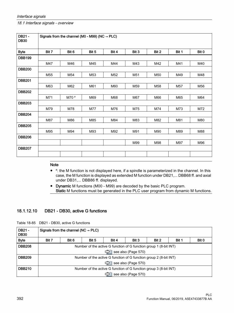
DB21 - DB30
Signals from the channel (M0 - M99) (NC → PLC)
Byte Bit 7 Bit 6 Bit 5 Bit 4 Bit 3 Bit 2 Bit 1 Bit 0DBB199
M47 M46 M45 M44 M43 M42 M41 M40DBB200
M55 M54 M53 M52 M51 M50 M49 M48DBB201
M63 M62 M61 M60 M59 M58 M57 M56DBB202
M71 M70 # M69 M68 M67 M66 M65 M64DBB203
M79 M78 M77 M76 M75 M74 M73 M72DBB204
M87 M86 M85 M84 M83 M82 M81 M80DBB205
M95 M94 M93 M92 M91 M90 M89 M88DBB206
M99 M98 M97 M96DBB207
Note● #: the M function is not displayed here, if a spindle is parameterized in the channel. In this
case, the M function is displayed as extended M function under DB21,... DBB68 ff. and axial under DB31,... DBB86 ff. displayed.
● Dynamic M functions (M00 - M99) are decoded by the basic PLC program. Static M functions must be generated in the PLC user program from dynamic M functions.
18.1.12.10 DB21 - DB30, active G functions
Table 18-85 DB21 - DB30, active G functions
DB21 - DB30
Signals from the channel (NC → PLC)
Byte Bit 7 Bit 6 Bit 5 Bit 4 Bit 3 Bit 2 Bit 1 Bit 0DBB208 Number of the active G function of G function group 1 (8-bit INT)
see also (Page 570)DBB209 Number of the active G function of G function group 2 (8-bit INT)
see also (Page 570)DBB210 Number of the active G function of G function group 3 (8-bit INT)
see also (Page 570)
Interface signals18.1 Interface signals - overview
PLC392 Function Manual, 06/2019, A5E47433877B AA

DB21 - DB30
Signals from the channel (NC → PLC)
Byte Bit 7 Bit 6 Bit 5 Bit 4 Bit 3 Bit 2 Bit 1 Bit 0DBB211 Number of the active G function of G function group 4 (8-bit INT)
see also (Page 570)DBB212 Number of the active G function of G function group 5 (8-bit INT)
see also (Page 570)DBB213 Number of the active G function of G function group 6 (8-bit INT)
see also (Page 570)DBB214 Number of the active G function of G function group 7 (8-bit INT)
see also (Page 570)DBB215 Number of the active G function of G function group 8 (8-bit INT)
see also (Page 570)... ...
DBB270 Number of the active G function of G function group n-1 (8-bit INT)see also (Page 570)
DBB271 Number of the active G function of G function group n (8-bit INT)see also (Page 570)
Note● The active G functions of the group, for each programming of a G function or a mnemonic
identifier (e.g. SPLINE), are updated.● G functions within a G group are output as binary value, starting with 1. A G function with the
value 0 means that for this G group, no G function is active.
18.1.12.11 DB21 - DB30, protection areas from the channel
Table 18-86 DB21 - DB30, signals for the protection zones from the channel
DB21 - DB30
Signals from the channel (NC → PLC)
Byte Bit 7 Bit 6 Bit 5 Bit 4 Bit 3 Bit 2 Bit 1 Bit 0DBB272 Machine-related protection zone preactivated
see also (Page 571)8 7 6 5 4 3 2 1
DBB273 Machine-related protection zone preactivatedsee also (Page 571)
10 9DBB274 Channel-specific protection zone preactivated
see also (Page 572)8 7 6 5 4 3 2 1
DBB275 Channel-specific protection zone preactivatedsee also (Page 572)
10 9
Interface signals18.1 Interface signals - overview
PLCFunction Manual, 06/2019, A5E47433877B AA 393

DB21 - DB30
Signals from the channel (NC → PLC)
Byte Bit 7 Bit 6 Bit 5 Bit 4 Bit 3 Bit 2 Bit 1 Bit 0DBB276 Machine-related protection zone violated
see also (Page 572)8 7 6 5 4 3 2 1
DBB277 Machine-related protection zone violatedsee also (Page 572)
10 9DBB278 Channel-specific protection zone violated
see also (Page 573)8 7 6 5 4 3 2 1
DBB279 Channel-specific protection zone violatedsee also (Page 573)
10 9
18.1.12.12 DB21 - DB30, synchronous actions, signals from/to the channel
Note
The request signals should be set in the PLC user program. After data transfer, they are reset by the basic PLC program.
Table 18-87 DB21 - DB30, job-controlled signals from/to the channel
DB21 - DB30/FBSY/
Signals to the channel (PLC ←→ NC)
Byte Bit 7 Bit 6 Bit 5 Bit 4 Bit 3 Bit 2 Bit 1 Bit 0DBB280PLC → NC
Require‐ment
Disable synchron‐
ized actions
Reserved
DBB281NC → PLC
Acknowl‐edgment
Synchron‐ized ac‐
tions disa‐bled
DBW282 -DBW298
Reserved
DBB300PLC → NC
Lock synchronized action 8 7 6 5 4 3 2 1
Interface signals18.1 Interface signals - overview
PLC394 Function Manual, 06/2019, A5E47433877B AA

DB21 - DB30/FBSY/
Signals to the channel (PLC ←→ NC)
Byte Bit 7 Bit 6 Bit 5 Bit 4 Bit 3 Bit 2 Bit 1 Bit 0DBB301PLC → NC
Lock synchronized action 16 15 14 13 12 11 10 9
DBB302PLC → NC
Lock synchronized action 24 23 22 21 20 19 18 17
DBB303PLC → NC
Lock synchronized action 32 31 30 29 28 27 26 25
DBB304PLC → NC
Lock synchronized action 40 39 38 37 36 35 34 33
DBB305PLC → NC
Lock synchronized action 48 47 46 45 44 43 42 41
DBB306PLC → NC
Lock synchronized action 56 55 54 53 52 51 50 49
DBB307PLC → NC
Lock synchronized action 64 63 62 61 60 59 58 57
DBB308NC → PLC
Synchronized action can be locked 8 7 6 5 4 3 2 1
DBB309NC → PLC
Synchronized action can be locked16 15 14 13 12 11 10 9
DBB310NC → PLC
Synchronized action can be locked 24 23 22 21 20 19 18 17
DBB311NC → PLC
Synchronized action can be locked 32 31 30 29 28 27 26 25
DBB312NC → PLC
Synchronized action can be locked 40 39 38 37 36 35 34 33
DBB313NC → PLC
Synchronized action can be locked48 47 46 45 44 43 42 41
DBB314NC → PLC
Synchronized action can be locked 56 55 54 53 52 51 50 49
DBB315NC → PLC
Synchronized action can be locked64 63 62 61 60 59 58 57
18.1.12.13 DB21 - DB30, control signals from/to the channel
Note
The request signals should be set in the PLC user program. After data transfer, they are reset by the basic PLC program.
Interface signals18.1 Interface signals - overview
PLCFunction Manual, 06/2019, A5E47433877B AA 395

Table 18-88 DB21 - DB30, job-controlled signals from/to the channel
DB21 - DB30
Signals from/to the channel (PLC ←→ NC)
Byte Bit 7 Bit 6 Bit 5 Bit 4 Bit 3 Bit 2 Bit 1 Bit 0DBB316 Active G functions
G00 geo.DBB317 Tool miss‐
ingsee
also (Page 575)
PTP tra‐versing ac‐
tivesee
also (Page 575)
Drive test travel re‐
quest
Target number of workpieces
reachedsee
also (Page 574)
External language
mode active
DBB318 Overstore active
/F1-A2/
Dry run fee‐drate active
/FB1-V1/
M01 associ‐ated with PLC active
see also
(Page 577)
Delayed stop
TOFF mo‐tion active
see also
(Page 576)
TOFF ac‐tive
see also
(Page 576)
Block search via program
test, SERU‐PRO, is ac‐
tivesee
also (Page 576)
ASUB stop‐ped
see also
(Page 575)
DBB319 No tool change
commands active
Feedrate stop
Delay Suppress
REPOS de‐lay
see also
(Page 579)
Feedrate stop
Delay
Active REPOS modesee also (Page 578)
Acknowl‐edgment of the REPOS
mode change
see also
(Page 577)
C B A
18.1.12.14 DB21 - DB30, signals to the orientation axes
Table 18-89 DB21 - DB30, signals to the orientation axes
DB21 - DB30
Signals to the channel (PLC → NC)
Byte Bit 7 Bit 6 Bit 5 Bit 4 Bit 3 Bit 2 Bit 1 Bit 0 Orientation axis 1 DBB320 Traversing keys
see also (Page 581)Rapid tra‐
verse over‐ride
see also
(Page 581)
Traversing key disable
see also
(Page 580)
Feedrate stop
Activate handwheelsee also (Page 579)
Plus Minus C B A
DBB321 Requested machine functionsee also (Page 583)
Continuous traversing
var. INC 10000 INC 1000 INC 100 INC 10 INC 1 INC
Interface signals18.1 Interface signals - overview
PLC396 Function Manual, 06/2019, A5E47433877B AA

DB21 - DB30
Signals to the channel (PLC → NC)
Byte Bit 7 Bit 6 Bit 5 Bit 4 Bit 3 Bit 2 Bit 1 Bit 0DBB322 OEM signals
DBB323 Handwheel
direction of rotation in‐
vertedsee
also (Page 584)
Orientation axis 2 DBB324 Traversing keys
see also (Page 585)Rapid tra‐
verse over‐ride
see also
(Page 585)
Traversing key disable
see also
(Page 584)
Feedrate stop
Activate handwheelsee also (Page 584)
Plus Minus C B A
DBB325 Requested machine functionsee also (Page 585)
Continuous traversing
var. INC 10000 INC 1000 INC 100 INC 10 INC 1 INC
DBB326 OEM signals
DBB327 Handwheel direction of rotation in‐
vertedsee
also (Page 585)
Orientation axis 3DBB328 Traversing keys
see also (Page 586)Rapid tra‐
verse over‐ride
see also
(Page 585)
Traversing key disable
see also
(Page 585)
Feedrate stop
Activate handwheelsee also (Page 585)
Plus Minus C B A
DBB329 Requested machine functionsee also (Page 586)
Continuous traversing
var. INC 10000 INC 1000 INC 100 INC 10 INC 1 INC
Interface signals18.1 Interface signals - overview
PLCFunction Manual, 06/2019, A5E47433877B AA 397

DB21 - DB30
Signals to the channel (PLC → NC)
Byte Bit 7 Bit 6 Bit 5 Bit 4 Bit 3 Bit 2 Bit 1 Bit 0DBB330 OEM signals
DBB331 Handwheel
direction of rotation in‐
vertedsee
also (Page 586)
18.1.12.15 DB21 - DB30, signals from the orientation axes
Table 18-90 DB21 - DB30, signals from the orientation axes
DB21 - DB30
Signals from the channel (NC → PLC)
Byte Bit 7 Bit 6 Bit 5 Bit 4 Bit 3 Bit 2 Bit 1 Bit 0 Orientation axis 1 DBB332 Traversing command
see also (Page 588)Travel requestsee also (Page 587)
Handwheel activesee also (Page 586)
Plus Minus Plus Minus C B ADBB333 Active machine function
see also (Page 589)Continuous traversing
active
INCvar INC10000 INC1000 INC100 INC10 INC1
DBB334 OEM signals
DBB335 Handwheel direction of rotation in‐version ac‐
tive Orientation axis 2 DBB336 Traversing command
see also (Page 590)Travel requestsee also (Page 590)
Handwheel activesee also (Page 589)
Plus Minus Plus Minus C B ADBB337 Active machine function
see also (Page 590)Continuous traversing
active
INCvar INC10000 INC1000 INC100 INC10 INC1
DBB338 OEM signals
Interface signals18.1 Interface signals - overview
PLC398 Function Manual, 06/2019, A5E47433877B AA
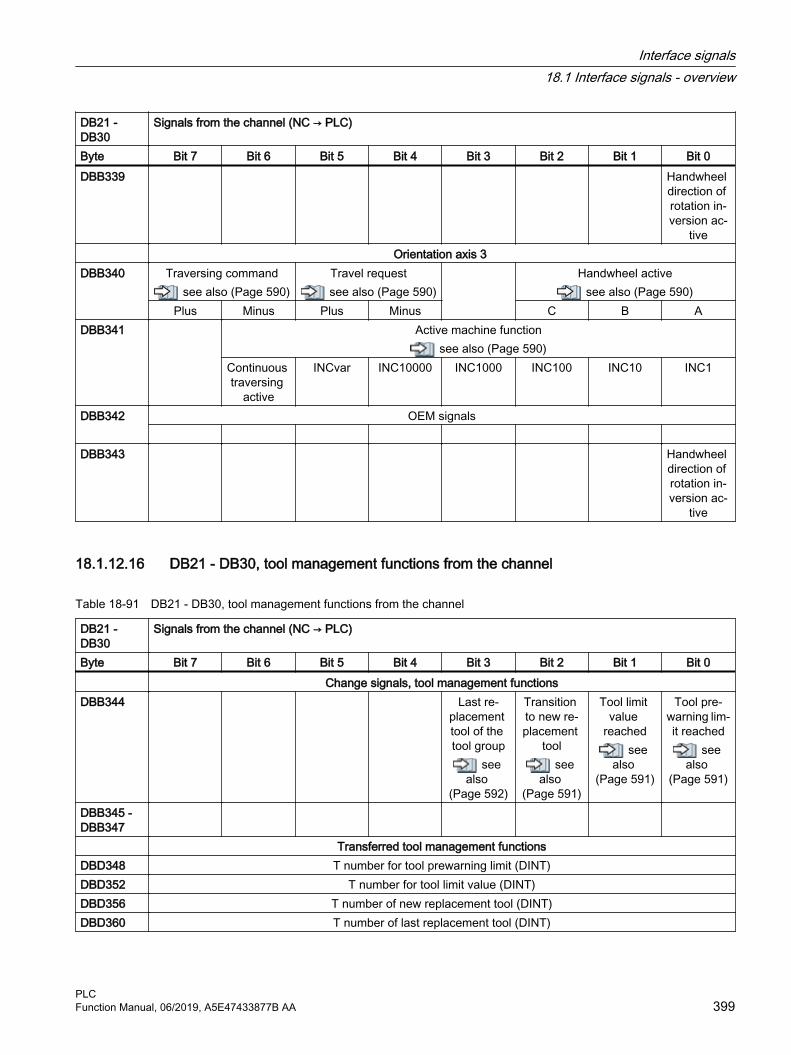
DB21 - DB30
Signals from the channel (NC → PLC)
Byte Bit 7 Bit 6 Bit 5 Bit 4 Bit 3 Bit 2 Bit 1 Bit 0DBB339 Handwheel
direction of rotation in‐version ac‐
tive Orientation axis 3 DBB340 Traversing command
see also (Page 590)Travel requestsee also (Page 590)
Handwheel activesee also (Page 590)
Plus Minus Plus Minus C B ADBB341 Active machine function
see also (Page 590)Continuous traversing
active
INCvar INC10000 INC1000 INC100 INC10 INC1
DBB342 OEM signals
DBB343 Handwheel direction of rotation in‐version ac‐
tive
18.1.12.16 DB21 - DB30, tool management functions from the channel
Table 18-91 DB21 - DB30, tool management functions from the channel
DB21 - DB30
Signals from the channel (NC → PLC)
Byte Bit 7 Bit 6 Bit 5 Bit 4 Bit 3 Bit 2 Bit 1 Bit 0 Change signals, tool management functionsDBB344 Last re‐
placement tool of the tool group
see also
(Page 592)
Transition to new re‐placement
toolsee
also (Page 591)
Tool limit value
reachedsee
also (Page 591)
Tool pre‐warning lim‐it reached
see also
(Page 591)
DBB345 - DBB347
Transferred tool management functionsDBD348 T number for tool prewarning limit (DINT)DBD352 T number for tool limit value (DINT)DBD356 T number of new replacement tool (DINT)DBD360 T number of last replacement tool (DINT)
Interface signals18.1 Interface signals - overview
PLCFunction Manual, 06/2019, A5E47433877B AA 399

18.1.12.17 DB21 - DB30, control signals from/to the channel (2)
Table 18-92 DB21 - DB30, signals from the channel
DB21 - DB30
Signals from the channel (NC → PLC)
Byte Bit 7 Bit 6 Bit 5 Bit 4 Bit 3 Bit 2 Bit 1 Bit 0DBB364 CH_CYCLES_SIG_IN (1)
8 7 6 5 4 3 2 1DBB365 CH_CYCLES_SIG_IN (2)
16 15 14 13 12 11 10 9DBB366 CH_CYCLES_SIG_OUT (1)
8 7 6 5 4 3 2 1DBB367 CH_CYCLES_SIG_OUT (2)
16 15 14 13 12 11 10 9DBB368 CH_OEM_TECHNO_SIG_IN (1)
8 7 6 5 4 3 2 1DBB369 CH_OEM_TECHNO_SIG_IN (2)
16 15 14 13 12 11 10 9DBB370 CH_OEM_TECHNO_SIG_IN (3)
24 23 22 21 20 19 18 17DBB371 CH_OEM_TECHNO_SIG_IN (4)
32 31 30 29 28 27 26 25DBB372 CH_OEM_TECHNO_SIG_OUT (1)
8 7 6 5 4 3 2 1DBB373 CH_OEM_TECHNO_SIG_OUT (2)
16 15 14 13 12 11 10 9DBB374 CH_OEM_TECHNO_SIG_OUT (3)
24 23 22 21 20 19 18 17DBB375 CH_OEM_TECHNO_SIG_OUT (4)
32 31 30 29 28 27 26 25DBB376 Display of the triggering event in case of event-driven program call
ProgEventDisplaysee also (Page 592)
DBB377 Jog circle
activesee
also (Page 594)
Retraction data availa‐
blesee
also (Page 593)
JOG retract active
see also
(Page 593)
Stop condi‐tion
Collision avoidance:
Stopsee
also (Page 593)
Interface signals18.1 Interface signals - overview
PLC400 Function Manual, 06/2019, A5E47433877B AA

DB21 - DB30
Signals from the channel (NC → PLC)
Byte Bit 7 Bit 6 Bit 5 Bit 4 Bit 3 Bit 2 Bit 1 Bit 0DBB378 "Silent"
ASUB is ac‐tive
see also
(Page 594)
ASUB is ac‐tive
see also
(Page 594)
DBB379 DBB380 Reserved ASUB
DBB381 Reserved ASUB
DBB382 Reserved ASUB
DBB383 Reserved ASUB
Table 18-93 DB21 - DB30, signals to the channel
DB21 - DB30
Signals to the channel (PLC → NC)
Byte Bit 7 Bit 6 Bit 5 Bit 4 Bit 3 Bit 2 Bit 1 Bit 0DBB384 Enable
GOTOSsee
also (Page 595)
DBB385 Grinding: Input signals 1 ... 8($AC_IN_KEY_G[1 ... 8])
8 7 6 5 4 3 2 1DBB386 Grinding: Disable input signals 1 ... 8
8 7 6 5 4 3 2 1DBB387 Grinding: Status of the grinding functions 1 ... 8
($AC_IN_KEY_G_RUN_IN[1...8])8 7 6 5 4 3 2 1
Interface signals18.1 Interface signals - overview
PLCFunction Manual, 06/2019, A5E47433877B AA 401

Table 18-94 DB21 - DB30, signals from/to channel
DB21 - DB30
Signals from/to the channel (NC ↔ PLC)
Byte Bit 7 Bit 6 Bit 5 Bit 4 Bit 3 Bit 2 Bit 1 Bit 0DBW388NC → PLC
Active transformation number
DBB390PLC → NC
Grinding: Enable status of input signals 1 ... 8($AC_IN_KEY_G_ISENABLE[1...8])
8 7 6 5 4 3 2 1DBB391NC → PLC
Grinding: Status of the grinding functions 1 ... 8($AC_IN_KEY_G_RUN_OUT[1...8])
8 7 6 5 4 3 2 1DBB392PLC → NC
Selection of the coordinate system for Cartesian manual traversing and handwheel override in the automatic mode in the tool direction (DRF)
see also (Page 597)DBB393 Reserved
DBB394 Reserved
DBB395 Reserved
DBB396 H function 1 (DInt), also in DBD142
DBB400 H function 2 (DInt), also in DBD146
DBB404 H function 3 (DInt), also in DBD150
Interface operating software -> PLCDBB 408HMI -> PLC
Axis selection type: 0: Machine axis, 1: Geo axis
DBB 409HMI -> PLC
Axis number: Machine/geo axis
DBB 410HMI -> PLC
KeyAxis selec‐tion
DBB 411 Interface PLC -> HMIDBB 412PLC -> HMI
Active axis selection (feedback message to the HMI)0: Machine axis, 1: Geo axis
DBB 413PLC -> HMI
Active axis number (feedback message to the HMI):Machine/geo axis
Interface signals18.1 Interface signals - overview
PLC402 Function Manual, 06/2019, A5E47433877B AA

18.1.13 Axis/spindle signals
18.1.13.1 DB31 - DB61, signals to the axis/spindle
Table 18-95 DB31 - DB61, signals to the axis/spindle
DB31 - DB61 Signals to the axis/spindle (PLC → NC)Byte Bit 7 Bit 6 Bit 5 Bit 4 Bit 3 Bit 2 Bit 1 Bit 0DBB0 Feedrate override, axis-specific
see also (Page 598)Bit 7 Bit 6 Bit 5 Bit 4 Bit 3 Bit 2 Bit 1 Bit 0
DBB1Axis and spindle
Override active
see also
(Page 608)
Position measuring sys‐tem 1 - 2
see also (Page 606)
Follow-up mode
see also
(Page 605)
Axis/spin‐dle disable
see also
(Page 602)
Sensor for fixed stop
see also
(Page 601)
Acknowl‐edge fixed
stop reached
see also
(Page 601)
Drive test travel ena‐
blesee
also (Page 600)
Bit 2 Bit 1
DBB2Axis and spindle
Reference point value 1 - 4see also (Page 613)
Clamping in progress
see also
(Page 613)
Delete dis‐tance-to-
go / spindle reset
see also
(Page 611)
Controller enable
see also
(Page 609)
Cam activa‐tion
see also
(Page 609)
Bit 4 Bit 3 Bit 2 Bit 1
DBB3Axis and spindle
Program test axis/spindle enable
Velocity / spindle
speed limi‐tation
see also
(Page 616)
Activate fixed feedratesee also (Page 615)
Travel to fixed stop enabled
see also
(Page 614)
Accept off‐set external
WOsee
also (Page 614)
Bit 4 Bit 3 Bit 2 Bit 1
DBB4Axis and spindle
Traversing keyssee also
(Page 619)
Rapid tra‐verse over‐
ridesee al‐
so (Page 619)
Traversing key disable
see also
(Page 618)
Feedrate stop / spin‐
dle stopsee
also (Page 617)
Activate handwheelsee also (Page 616)
Plus Minus Bit 3 Bit 2 Bit 1
DBB5Axis and spindle
Machine functionsee also (Page 620)
Continuous manual travel
INCvar INC10000 INC1000 INC100 INC10 INC1
DBB6 OEM signalsBit 7 Bit 6 Bit 5 Bit 4 Bit 3 Bit 2 Bit 1 Bit 0
Interface signals18.1 Interface signals - overview
PLCFunction Manual, 06/2019, A5E47433877B AA 403

DB31 - DB61 Signals to the axis/spindle (PLC → NC)Byte Bit 7 Bit 6 Bit 5 Bit 4 Bit 3 Bit 2 Bit 1 Bit 0DBB7 OEM signals
Bit 7 Bit 6 Bit 5 Bit 4 Bit 3 Bit 2 Bit 1 Invert hand‐wheel direc‐tion of rota‐
tionsee
also (Page 621)
DBB8 Request PLC axis/
spindle
Channel assign‐ment
changed
NC axis / spindle channel assignmentsee also (Page 622)
Bit 3 Bit 2 Bit 1 Bit 0
DBB9 Parameter set change
inhibitedsee
also (Page 623)
Controller parameter setsee also (Page 623)
Bit 2 Bit 1 Bit 0
DBB10 REPOS de‐laysee
also (Page 623)
DBB11 SI:Start brake
testDBB12Axis
Delay ref‐erence point ap‐proach
see also
(Page 625)
Modulo ro‐tary axes: Activate
traversing range limits
see also (Page 625)
2nd software limit switch Hardware limit switchPlus
see also (Page 625)
Minussee
also (Page 625)
Plussee
also (Page 624)
Minussee
also (Page 624)
DBB13Axis
JOG to po‐sition
see also
(Page 626)
JOG fixed point approachsee also (Page 626)
Bit 2 Bit 1 Bit 0
DBB14Axis
Program testActivate
see also
(Page 628)
Suppresssee
also (Page 627)
DBB15Axis
Interface signals18.1 Interface signals - overview
PLC404 Function Manual, 06/2019, A5E47433877B AA

DB31 - DB61 Signals to the axis/spindle (PLC → NC)Byte Bit 7 Bit 6 Bit 5 Bit 4 Bit 3 Bit 2 Bit 1 Bit 0DBB16Spindle
Delete S value
see also
(Page 631)
No speed monitoring during gear
change
Resynchronize spindle
Gear is changed
oversee
also (Page 630)
Actual gear stagesee also (Page 628)
Measuring system 2
see al‐so
(Page 630)
Measuring system 1
see also
(Page 629)
Bit 2 Bit 1 Bit 0
DBB17Spindle
Invert M3/M4
see also
(Page 632)
Resynchronize spindle during positioning
Feedrate correction spindle val‐
idMeasuring system 2
see al‐so
(Page 631)
Measuring system 1
see also
(Page 631)DBB18Spindle
Oscillation direction of rotation
Oscillation enable
see al‐so
(Page 633)
Oscillation controlled
by PLCsee
also (Page 632)
Linkssee
also (Page 634)
Rightsee
also (Page 633)
DBB19Spindle
Speed override, spindle-specificsee also (Page 635)
Bit 7 Bit 6 Bit 5 Bit 4 Bit 3 Bit 2 Bit 1 Bit 0DBB20Drive
Open motor holding brake
Ramp-func‐tion genera‐tor disable 1)
see also
(Page 637)
DBB21Drive
Pulse ena‐ble
see also
(Page 640)
Integrator disable,
speed con‐troller
see also
(Page 639)
Motor being selected
see al‐so
(Page 639)
Motor/drive data set: Selection(interface definition: DB31, …DBX130.0 - 4 (Page 408))
see also (Page 638)Bit 4 Bit 3 Bit 2 Bit 1 Bit 0
DBB22Safety Inte‐grated
SI: SG selectionsee also (Page 640)
SI: Ac‐knowledg‐ment, com‐munication
failure
SI:SBH dese‐
lectionsee
also (Page 640)
SI:SBH/SG
deselectionsee
also (Page 640)
Bit 1 Bit 0
Interface signals18.1 Interface signals - overview
PLCFunction Manual, 06/2019, A5E47433877B AA 405
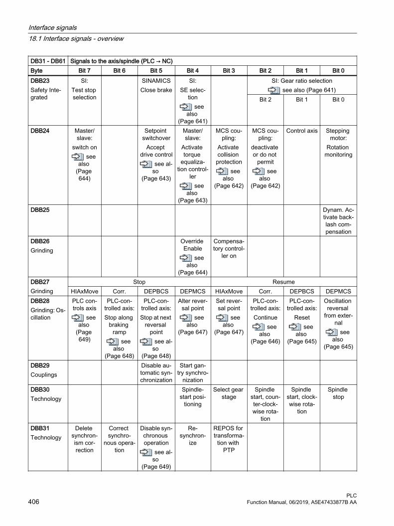
DB31 - DB61 Signals to the axis/spindle (PLC → NC)Byte Bit 7 Bit 6 Bit 5 Bit 4 Bit 3 Bit 2 Bit 1 Bit 0DBB23Safety Inte‐grated
SI:Test stop selection
SINAMICSClose brake
SI:SE selec‐
tionsee
also (Page 641)
SI: Gear ratio selectionsee also (Page 641)
Bit 2 Bit 1 Bit 0
DBB24 Master/slave:
switch onsee
also (Page 644)
Setpoint switchover
Accept drive control
see al‐so
(Page 643)
Master/slave:
Activate torque
equaliza‐tion control‐
lersee
also (Page 643)
MCS cou‐pling:
Activate collision protection
see also
(Page 642)
MCS cou‐pling:
deactivate or do not
permitsee
also (Page 642)
Control axis Stepping motor:
Rotation monitoring
DBB25 Dynam. Ac‐tivate back‐lash com‐pensation
DBB26Grinding
Override Enable
see also
(Page 644)
Compensa‐tory control‐
ler on
DBB27Grinding
Stop ResumeHIAxMove Corr. DEPBCS DEPMCS HIAxMove Corr. DEPBCS DEPMCS
DBB28Grinding: Os‐cillation
PLC con‐trols axis
see also
(Page 649)
PLC-con‐trolled axis:Stop along
braking ramp
see also
(Page 648)
PLC-con‐trolled axis:Stop at next
reversal point
see al‐so
(Page 648)
Alter rever‐sal point
see also
(Page 647)
Set rever‐sal point
see also
(Page 647)
PLC-con‐trolled axis:Continue
see also
(Page 646)
PLC-con‐trolled axis:
Resetsee
also (Page 645)
Oscillation reversal
from exter‐nal
see also
(Page 645)
DBB29Couplings
Disable au‐tomatic syn‐chronization
Start gan‐try synchro‐
nization
DBB30Technology
Spindle-start posi‐
tioning
Select gear stage
Spindle start, coun‐ter-clock‐wise rota‐
tion
Spindle start, clock‐wise rota‐
tion
Spindle stop
DBB31Technology
Delete synchron‐ism cor‐rection
Correct synchro‐
nous opera‐tion
Disable syn‐chronous operation
see al‐so
(Page 649)
Re‐synchron‐
ize
REPOS for transforma‐
tion with PTP
Interface signals18.1 Interface signals - overview
PLC406 Function Manual, 06/2019, A5E47433877B AA

DB31 - DB61 Signals to the axis/spindle (PLC → NC)Byte Bit 7 Bit 6 Bit 5 Bit 4 Bit 3 Bit 2 Bit 1 Bit 0DBB32Safety Inte‐grated
SI: Dese‐lect exter‐
nal STOP_E
SI: Dese‐lect exter‐
nal STOP_D
SI: Dese‐lect exter‐
nal STOP_C
SI: Dese‐lect exter‐
nal STOP_A
DBB33Safety Inte‐grated
SI: SG override selection/override Bit 3 Bit 2 Bit 1 Bit 0
DBB34 Setpoint limitationBit 1 Bit 0
DBB35 DBB36Technology
DBB37 DBB38 DBB39 DBB40 - DBB55
DBB56PLC → HMI
Spindle in‐ternal
clamping
Spindle speed dis‐
play
Separate feedrate drive cou‐pled as C
axisDBB57 DBB58 ReservedDBB59 DBB188 DBB189 Motor over‐
tempera‐ture: Disa‐ble current reduction
DYNEG‐MA: Disa‐
ble derating
1) Only when cyclic interface between NC and drive is operated in the "611U compatibility mode".
Note
DBX8.4 is automatically reset after the assignment is executed
Interface signals18.1 Interface signals - overview
PLCFunction Manual, 06/2019, A5E47433877B AA 407

18.1.13.2 DB31 - DB61, signals from the axis/spindle
Table 18-96 DB31 - DB61, signals from the axis/spindle
DB31 - DB61
Signals from the axis/spindle (NC → PLC)
Byte Bit 7 Bit 6 Bit 5 Bit 4 Bit 3 Bit 2 Bit 1 Bit 0DBB60Axis / spin‐dle
Position reached with ex‐act stop
Referenced/synchronizedPosition measuring sys‐
tem
Encoder limit frequency exceeded, measuring
system
NCU link:Axis active
see also
(Page 651)
Spindle / ro‐tary axis
see also
(Page 650)fine
see also
(Page 654)
coarsesee
also (Page 653)
2see
also (Page 653)
1see
also (Page 652)
2see
also (Page 651)
1see
also (Page 651)
DBB61Axis / spin‐dle
Current controller
activesee
also (Page 658)
Speed con‐troller active
see also
(Page 657)
Position controller
activesee
also (Page 657)
Axis/spin‐dle station‐ary (n < nmin)
see also
(Page 656)
Follow-up mode active
see also
(Page 655)
Axis readysee
also (Page 655)
Axis-specif‐ic alarm
see also
(Page 655)
Drive testtravel re‐
questsee
also (Page 654)
DBB62 Axis con‐tainer:
Rotation ac‐tive
see also
(Page 660)
Travel to fixed stop:Force limit‐ing active
Travel to fixed stop:Fixed stop
reachedsee
also (Page 660)
Travel to fixed stop:Activating
the functionsee
also (Page 660)
Measure‐ment active
see also
(Page 659)
Revolution‐al feedrate
activesee
also (Page 659)
Handwheel override ac‐
tivesee
also (Page 658)
Software cams active
see also
(Page 658)
DBB63 Stop Axis/spin‐dle disable
active
Axis stop active
see also
(Page 661)
PLC-con‐trolled axis
see also
(Page 661)
Reset exe‐cuted
see also
(Page 661)
HIAxMove active
Corr. active DEPBCS active
DEPMCS active
DBB64Axis / spin‐dle
Traversing commandsee also (Page 664)
Travel requestsee also (Page 663)
Handwheel activesee also (Page 662)
Plus Minus Plus Minus Bit 2 Bit 1 Bit 0DBB65Axis / spin‐dle
Active machine functionsee also (Page 664)
Continuous manual travel
INCvar INC10000 INC1000 INC100 INC10 INC1
DBB66Axis / spin‐dle
MCS cou‐pling:
Collision protection
activesee
also (Page 665)
Interface signals18.1 Interface signals - overview
PLC408 Function Manual, 06/2019, A5E47433877B AA

DB31 - DB61
Signals from the axis/spindle (NC → PLC)
Byte Bit 7 Bit 6 Bit 5 Bit 4 Bit 3 Bit 2 Bit 1 Bit 0DBB67 Handwheel
direction of rotation in‐version ac‐
tivesee
also (Page 665)
DBB68 Status axis/spindle replacement see also (Page 666)
PLC axis/spindle
Neutral ax‐is/spindle
Axis inter‐change possible
New type requested from PLC
NC axis / spindle channel assignmentBit 3 Bit 2 Bit 1 Bit 0
DBB69 NCU number in the NCU link group Controller parameter set servosee also (Page 666)
Bit 4 Bit 3 Bit 2 Bit 1 Bit 0 Bit 2 Bit 1 Bit 0DBB70 DRV Safety
Integrated active with SIC/SCC
NC Safety Integrated
active
REPOS de‐lay ac‐
knowledg‐ment
see also
(Page 668)
REPOS off‐set valid
see also
(Page 668)
REPOS off‐set
see also
(Page 667)
DBB71 PLC axis permanent‐ly assigned
Position restored Brake test activeEncoder 2
see also
(Page 669)
Encoder 1see
also (Page 669)
DBB72HMI → PLC
REPOS de‐lay active
see also
(Page 670)DBB73HMI → PLC
DBB74Axis
Modulo ro‐tary axes:
Traversing range limits
activesee
also (Page 670)
Interface signals18.1 Interface signals - overview
PLCFunction Manual, 06/2019, A5E47433877B AA 409

DB31 - DB61
Signals from the axis/spindle (NC → PLC)
Byte Bit 7 Bit 6 Bit 5 Bit 4 Bit 3 Bit 2 Bit 1 Bit 0DBB75Axis
JOG posi‐tion
reachedsee
also (Page 672)
JOG travel to position
activesee
also (Page 672)
JOG approach fixed point reachedsee also (Page 671)
JOG approach fixed point activesee also (Page 671)
Bit 2 Bit 1 Bit 0 Bit 2 Bit 1 Bit 0
DBB76Axis
Rounding axis in posi‐
tion
Indexing axis in posi‐
tionsee
also (Page 673)
Positioning axis
see also
(Page 673)
Path axissee
also (Page 673)
Lubrication pulse
see also
(Page 672)
DBB77Axis
Collision avoidance: Velocity re‐
ductionsee
also (Page 674)
DBD78Axis
F value (REAL) for positioning axissee also (Page 674)
DBB82Spindle
Change gear stage
see also
(Page 675)
Setpoint gear stagesee also (Page 675)
Bit 2 Bit 1 Bit 0
DBB83Spindle
Actual di‐rection of rotation
clockwisesee
also (Page 679)
Speed monitoring
see also
(Page 679)
Spindle in setpoint
rangesee
also (Page 679)
Support range limits
violated
Geometry monitoring
see also
(Page 678)
Speed setpoint Speed limit exceeded
see also
(Page 678)
Increasedsee
also (Page 676)
limitedsee
also (Page 676)
DBB84Spindle
Active spindle mode Tapping without
compensat‐ing chuck
activesee
also (Page 680)
CLGON ac‐tive
GWPS ac‐tive
see also
(Page 680)
Const. cut‐ting velocity
activeControl mode
see also
(Page 682)
Oscillation mode
see also
(Page 681)
Positioning mode
see also
(Page 681)
Synchro‐nous opera‐
tionsee
also (Page 681)
DBB85Spindle
Spindle ac‐tually
reached po‐sition
see also
(Page 682)
Tool with dynamic re‐sponse limi‐
tationsee
also (Page 682)
Interface signals18.1 Interface signals - overview
PLC410 Function Manual, 06/2019, A5E47433877B AA
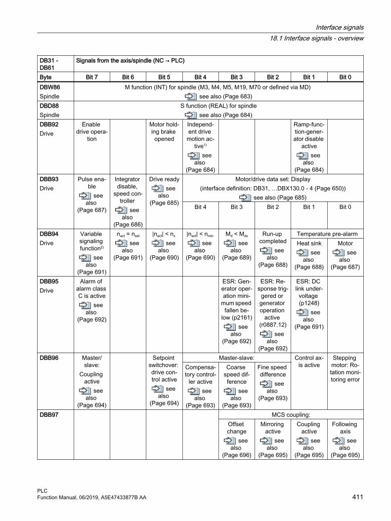
DB31 - DB61
Signals from the axis/spindle (NC → PLC)
Byte Bit 7 Bit 6 Bit 5 Bit 4 Bit 3 Bit 2 Bit 1 Bit 0DBW86Spindle
M function (INT) for spindle (M3, M4, M5, M19, M70 or defined via MD) see also (Page 683)
DBD88Spindle
S function (REAL) for spindlesee also (Page 684)
DBB92Drive
Enable drive opera‐
tion
Motor hold‐ing brake opened
Independ‐ent drive motion ac‐
tive1)
see also
(Page 684)
Ramp-func‐tion-gener‐ator disable
activesee
also (Page 684)
DBB93Drive
Pulse ena‐ble
see also
(Page 687)
Integrator disable,
speed con‐troller
see also
(Page 686)
Drive readysee
also (Page 685)
Motor/drive data set: Display(interface definition: DB31, …DBX130.0 - 4 (Page 650))
see also (Page 685)Bit 4 Bit 3 Bit 2 Bit 1 Bit 0
DBB94Drive
Variable signaling function2)
see also
(Page 691)
nact = nset
see also
(Page 691)
|nact| < nx
see also
(Page 690)
|nact| < nmin
see also
(Page 690)
Md < Mdx
see also
(Page 689)
Run-up completed
see also
(Page 688)
Temperature pre-alarmHeat sink
see also
(Page 688)
Motorsee
also (Page 687)
DBB95Drive
Alarm of alarm class C is active
see also
(Page 692)
ESR: Gen‐erator oper‐ation mini‐
mum speed fallen be‐
low (p2161)see
also (Page 692)
ESR: Re‐sponse trig‐
gered or generator operation
active (r0887.12)
see also
(Page 692)
ESR: DC link under‐
voltage (p1248)
see also
(Page 691)
DBB96 Master/slave:
Coupling active
see also
(Page 694)
Setpoint switchover: drive con‐trol active
see also
(Page 694)
Master-slave: Control ax‐is active
Stepping motor: Ro‐tation moni‐toring error
Compensa‐tory control‐
ler activesee
also (Page 693)
Coarse speed dif‐ference
see also
(Page 693)
Fine speed difference
see also
(Page 693)
DBB97 MCS coupling:Offset change
see also
(Page 696)
Mirroring active
see also
(Page 695)
Coupling active
see also
(Page 695)
Following axis
see also
(Page 695)
Interface signals18.1 Interface signals - overview
PLCFunction Manual, 06/2019, A5E47433877B AA 411

DB31 - DB61
Signals from the axis/spindle (NC → PLC)
Byte Bit 7 Bit 6 Bit 5 Bit 4 Bit 3 Bit 2 Bit 1 Bit 0DBB98Synchro‐nous spin‐dle
ESR re‐sponse initi‐
ated
Accelera‐tion warn‐ing thresh‐old reached
see also
(Page 699)
Velocity warning
threshold reached
see also
(Page 698)
Superim‐posed mo‐
tionsee
also (Page 698)
Actual val‐ue coupling
see also
(Page 697)
Synchronous operationcoarse
see also
(Page 697)
finesee
also (Page 696)
DBB99Synchro‐nous spin‐dle
Max. accel‐eration reached
Max. veloci‐ty reached
Synchroni‐zation in progress
Axis accel‐erating
see also
(Page 700)
Synchron‐ism correc‐tion imple‐
mented
Following spindle ac‐
tivesee
also (Page 700)
Leading spindle ac‐
tivesee
also (Page 699)
DBB100Oscillation grinding
Oscillation active
see also
(Page 702)
Oscillation motion ac‐
tivesee
also (Page 701)
Sparking-out active
see also
(Page 701)
Fault dur‐ing oscilla‐tion motion
see also
(Page 701)
Oscillation cannot be
started work for now I get why you
see also
(Page 701)
Oscillation reversal
from exter‐nal active
see also
(Page 700)
DBB101Gantry
Gantry axis Gantry guide axis
Gantry grouping is
synchro‐nous
Gantry syn‐chroniza‐
tion ready to start
Gantry alarm limit exceeded
Gantry shutdown limit excee‐
ded
DBB102
Position measuring sys‐tem activated
Clamping tolerance exceeded
Dynam. Backlash
compensa‐tion active
2see
also (Page 702)
1see
also (Page 702)
DBB103 Synchronous operation 2 Synchron‐ism correc‐tion is tak‐en into ac‐
count
coarse fine
DBB104Grinding
Active infeed axissee also (Page 703)
8 7 6 5 4 3 2 1DBB105Grinding
Active infeed axis16 15 14 13 12 11 10 9
DBB106Grinding
Active infeed axis24 23 22 21 20 19 18 17
DBB107Grinding
Active infeed axis 31 30 29 28 27 26 25
Interface signals18.1 Interface signals - overview
PLC412 Function Manual, 06/2019, A5E47433877B AA

DB31 - DB61
Signals from the axis/spindle (NC → PLC)
Byte Bit 7 Bit 6 Bit 5 Bit 4 Bit 3 Bit 2 Bit 1 Bit 0DBB108Safety Inte‐grated
SI:Axis safely referenced
SI:Communi‐cation fail‐ure not ac‐
knowl‐edged
SI:CRC error
SI:Status, pul‐ses are can‐
celed
SI:CRC or
sign-of-life error
SI:SBH/SG
active
DBB109Safety Inte‐grated
SI: Output cam positionSN 4- SN 4+ SN 3- SN 3+ SN 2- SN 2+ SN 1- SN 1+
DBB110Safety Inte‐grated
n < nx SI: Active SG SI:SBH active
B A
DBB111Safety Inte‐grated
SI: Stop A - E Stop EActive
Stop DActive
Stop CActive
Stop A/BActive
DBB112Safety Inte‐grated
Output cam range for cam track 1
DBB113Safety Inte‐grated
Output cam range for cam track 2
DBB114Safety Inte‐grated
Output cam range for cam track 3
DBB115Safety Inte‐grated
Output cam range for cam track 4
DBB116Safety Inte‐grated
Reserved
DBB117Safety Inte‐grated
Reserved Output cam track 4 3 2 1
DBB118Safety Inte‐grated
SI: Cam range bit for cam track 17 6 5 4 3 2 1 0
DBB119Safety Inte‐grated
SI: Cam range bit for cam track 1 14 13 12 11 10 9 8
DBB120Safety Inte‐grated
SI: Cam range bit for cam track 27 6 5 4 3 2 1 0
DBB121Safety Inte‐grated
SI: Cam range bit for cam track 2 14 13 12 11 10 9 8
Interface signals18.1 Interface signals - overview
PLCFunction Manual, 06/2019, A5E47433877B AA 413

DB31 - DB61
Signals from the axis/spindle (NC → PLC)
Byte Bit 7 Bit 6 Bit 5 Bit 4 Bit 3 Bit 2 Bit 1 Bit 0DBB122Safety Inte‐grated
SI: Cam range bit for cam track 37 6 5 4 3 2 1 0
DBB123Safety Inte‐grated
SI: Cam range bit for cam track 3 14 13 12 11 10 9 8
DBB124Safety Inte‐grated
SI: Cam range bit for cam track 47 6 5 4 3 2 1 0
DBB125Safety Inte‐grated
SI: Cam range bit for cam track 4 14 13 12 11 10 9 8
DBB126
DBB127
DBB128HMI → PLC
Program testActivate
see also
(Page 704)
Suppresssee
also (Page 703)
DBB129 DBB130 Motor/drive
data set:Formatting
is valid
Motor/drive data set: Formatting(interface definition: DB31, …DBX21.0 ... 4 (Page 403),
DB 31. ...DBX93.0 ... 4 (Page 685))see also (Page 704)
Bit 4 Bit 3 Bit 2 Bit 1 Bit 0DBB131 DBB132Weiss spin‐dle
Sensor configuration Sensor S6
availableSensor S5 available
(angular po‐sition, mo‐tor shaft)
see also
(Page 705)
Sensor S4 available
(piston end position)
see also
(Page 705)
Sensor S1 available (clamped
state)see
also (Page 705)
Sensors available
see also
(Page 704)
Interface signals18.1 Interface signals - overview
PLC414 Function Manual, 06/2019, A5E47433877B AA

DB31 - DB61
Signals from the axis/spindle (NC → PLC)
Byte Bit 7 Bit 6 Bit 5 Bit 4 Bit 3 Bit 2 Bit 1 Bit 0DBB133Weiss spin‐dle
Sensor configuration Status val‐
ue is gener‐ated, speed limitation
p5043 is ac‐tive
see also
(Page 706)
DBW134Weiss spin‐dle
Clamping state (sensor S1) status valuesee also (Page 706)
DBW136Weiss spin‐dle
Clamping state (sensor S1) analog valuesee also (Page 707)
DBB138Weiss spin‐dle
Status digital sensors Sensor S5
angular po‐sition, mo‐tor shaft
see also
(Page 708)
Sensor S4, piston end
positionsee
also (Page 708)
DBB139Weiss spin‐dle
Status digital sensors
DBB190 Encoder servicing required
DBB191 OR opera‐tion: Condi‐tion fulfilled
AND opera‐tion: Condi‐tion fulfilled
Pole posi‐tion identifi‐cation with encoder
successful‐ly carried
out
Motor overtemperature DYNEG‐MA: Torque limit applied
Motor tem‐perature model
warning pending
Current re‐duction ac‐
tive
1) With SINAMICS valid for NC 62.07 and higher when using a 611U telegram type2) With SINAMICS valid for SW2.6 and higher
Interface signals18.1 Interface signals - overview
PLCFunction Manual, 06/2019, A5E47433877B AA 415

18.1.14 Safety Integrated
18.1.14.1 DB31 - DB61, Safety Control Channel (SCC)
Table 18-97 DB31 - DB61, axis signals: Safety Control Channel (SCC)
DB31 - DB61/FBSIsl/
Signals to the axis/spindle
Byte Bit 7 Bit 6 Bit 5 Bit 4 Bit 3 Bit 2 Bit 1 Bit 0 SCC (PLC → drive)DBB140
Test stops for exten‐ded func‐
tionsDBB141 DBB142 DBB143 External
brake closed(SBC)
Test se‐quence 1 or
2
Direction of rotation
Test with brake 1 or 2
(SBT)
Start brake test
(SBT)
Select safe brake test
(SBT)
DBB144 ...DBB163
18.1.14.2 DB31 - DB61, Safety Info Channel (SIC)
Table 18-98 DB31 - DB61, axis signals: Safety Info Channel (SIC)
DB31 - DB61/FBSIsl/
Signals from axis/spindle
Byte Bit 7 Bit 6 Bit 5 Bit 4 Bit 3 Bit 2 Bit 1 Bit 0 SIC (drive → PLC)DBB164 Safety error
activeESR re‐quested
Bit 1 limit value
Safely limi‐ted speed
(SLS)
Bit 0 limit value
Safely limi‐ted speed
(SLS)
Safely limi‐ted acceler‐
ation(SLA)
DBB165 Safety error with Stop A
Safely-limi‐ted speed selected
(SLS)
Safe oper‐ating stop selected(SOS)
Safely-limi‐ted speed
active(SLS)
Safe oper‐ating stop
active(SOS)
Safe stop 2(SS2)
Safe stop 1(SS1)
Safe torque off
(STO)
DBB166 Accept‐ance test stop re‐quested
Accept‐ance test
stop active
Safe direc‐tion nega‐
tive(SDI)
Safe direc‐tion positive
(SDI)
Interface signals18.1 Interface signals - overview
PLC416 Function Manual, 06/2019, A5E47433877B AA
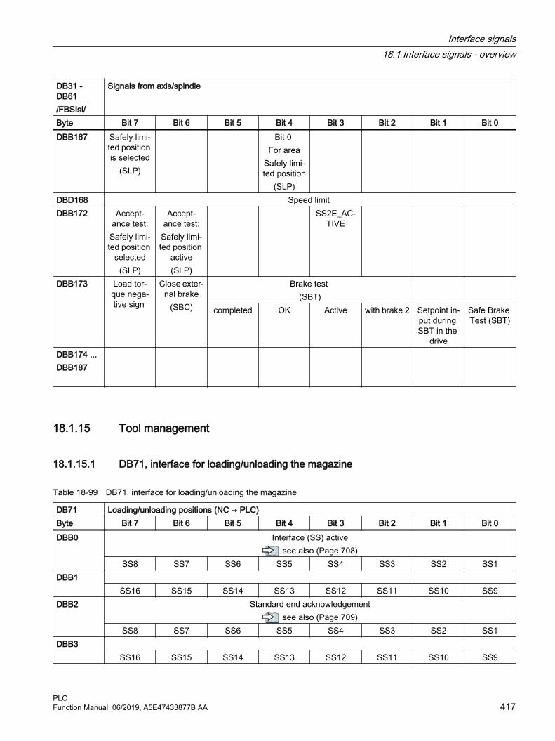
DB31 - DB61/FBSIsl/
Signals from axis/spindle
Byte Bit 7 Bit 6 Bit 5 Bit 4 Bit 3 Bit 2 Bit 1 Bit 0DBB167 Safely limi‐
ted position is selected
(SLP)
Bit 0 For area
Safely limi‐ted position
(SLP)
DBD168 Speed limit DBB172 Accept‐
ance test:Safely limi‐ted position
selected(SLP)
Accept‐ance test:Safely limi‐ted position
active(SLP)
SS2E_AC‐TIVE
DBB173 Load tor‐que nega‐tive sign
Close exter‐nal brake
(SBC)
Brake test (SBT)
completed OK Active with brake 2 Setpoint in‐put during SBT in the
drive
Safe Brake Test (SBT)
DBB174 ...DBB187
18.1.15 Tool management
18.1.15.1 DB71, interface for loading/unloading the magazine
Table 18-99 DB71, interface for loading/unloading the magazine
DB71 Loading/unloading positions (NC → PLC)Byte Bit 7 Bit 6 Bit 5 Bit 4 Bit 3 Bit 2 Bit 1 Bit 0DBB0 Interface (SS) active
see also (Page 708)SS8 SS7 SS6 SS5 SS4 SS3 SS2 SS1
DBB1 SS16 SS15 SS14 SS13 SS12 SS11 SS10 SS9
DBB2 Standard end acknowledgementsee also (Page 709)
SS8 SS7 SS6 SS5 SS4 SS3 SS2 SS1DBB3
SS16 SS15 SS14 SS13 SS12 SS11 SS10 SS9
Interface signals18.1 Interface signals - overview
PLCFunction Manual, 06/2019, A5E47433877B AA 417

DB71 Loading/unloading positions (NC → PLC)Byte Bit 7 Bit 6 Bit 5 Bit 4 Bit 3 Bit 2 Bit 1 Bit 0DBBn + 0 Reserved Command:
Multitool positioning
see also
(Page 711)
NC progr. positions magazine
see also
(Page 711)
Positioning to the load‐
ing pointsee
also (Page 710)
Relocatingsee
also (Page 710)
Unloadingsee
also (Page 709)
Loadingsee
also (Page 709)
DBBn + 1 Command: Data in ex‐
tended Area
(DB1071 (Page 431))
see also
(Page 712)
Reserved Acknowl‐edgement status = 3
see also
(Page 711)
DBBn + 2 Assigned channel (8-bit INT)see also (Page 712)
DBBn + 3 Tool management no. (8-bit INT)see also (Page 712)
DBBn + 4 Reserved (free parameter 1 (DWord))DBBn + 8 Reserved (free parameter 2 (DWord))DBDn + 12 Reserved (free parameter 3 (DWord))DBWn + 16 Identifier for loading/unloading point (INT), (fixed value 9999)
see also (Page 713)DBWn + 18 Location no. of load/unload point (INT)
see also (Page 713)DBWn + 20 Magazine no. (Source) for unloading/relocating/positioning (INT)
see also (Page 713)DBWn + 22 Location no. (Source) for unloading/relocating/positioning (INT)
see also (Page 714)DBWn + 24 Magazine no. (Target) for loading/relocating/positioning (INT)
see also (Page 714)DBWn + 26 Location no. (Target) for loading/relocating/positioning (INT)
see also (Page 715)DBWn + 28 Reserved Loading/
unloading without moving
magazinesee
also (Page 715)
DBWn + 29 Reserved
Interface signals18.1 Interface signals - overview
PLC418 Function Manual, 06/2019, A5E47433877B AA

Starting addresses of loading/unloading points:
Loading/unloading point 1: n = 4 Loading/unloading point 3: n = 64Loading/unloading point 2: n = 34 Loading/unloading point 4: n = 94
Loading interface 1 is responsible for loading/unloading in (all) spindles/toolholders and for relocating tools and for positioning at any locations (e.g. buffer location).
Loading and unloading manual tools is always realized via loading interface 1.
18.1.15.2 DB72, interface for the spindle as change position
Table 18-100 DB72, interface for the spindle as change position
DB72 Signals from the spindle (NC → PLC)Byte Bit 7 Bit 6 Bit 5 Bit 4 Bit 3 Bit 2 Bit 1 Bit 0DBB0 Interface (SS) active
see also (Page 716)SS8 SS7 SS6 SS5 SS4 SS3 SS2 SS1
DBB1 SS16 SS15 SS14 SS13 SS12 SS11 SS10 SS9
DBB2 Standard end acknowledgmentsee also (Page 716)
SS8 SS7 SS6 SS5 SS4 SS3 SS2 SS1DBB3
SS16 SS15 SS14 SS13 SS12 SS11 SS10 SS9DBBn + 0 Command code:
Spindle tool remains in the spindle
see also
(Page 720)
Replace manual tool
see also
(Page 719)
Insert man‐ual tool
see also
(Page 719)
Old T in buf‐fer
see also
(Page 718)
T0see
also (Page 718)
Prepare change
see also
(Page 717)
Perform change (ini‐tiate: M06)
see also
(Page 717)
Obligatory change
see also
(Page 716)
DBBn + 1 Data in ex‐tended Area
(DB1072 (Page 432))
see also
(Page 721)
Reserved Acknowl‐edgment status = 3
see also
(Page 720)
DBBn + 2 Assigned channel (8-bit INT)see also (Page 721)
DBBn + 3 Tool management No. (8-bit INT)see also (Page 721)
DBDn + 4 User parameter 0 (DWord)see also (Page 721)
Interface signals18.1 Interface signals - overview
PLCFunction Manual, 06/2019, A5E47433877B AA 419

DB72 Signals from the spindle (NC → PLC)Byte Bit 7 Bit 6 Bit 5 Bit 4 Bit 3 Bit 2 Bit 1 Bit 0DBDn + 8 User parameter 1 (DWord)
see also (Page 722)DBDn + 12 User parameter 2 (DWord)
see also (Page 722)DBWn + 16 Buffer identifier (INT), (fixed value 9998)
(corresponds to "Target position for new tool")see also (Page 722)
DBWn + 18 Relative location (target) in buffer magazine (INT)see also (Page 723)
DBWn + 20 Magazine No. (Source) for new tool (INT)see also (Page 723)
DBWn + 22 Location No. (Source) for new tool (INT)see also (Page 723)
DBWn + 24 Magazine No. (Target) for old tool (INT)see also (Page 724)
DBWn + 26 Location No. (Target) for old tool (INT)see also (Page 724)
DBWn + 28 Tool new: Location type (INT)see also (Page 724)
DBWn + 30 Tool new: Size left (INT)see also (Page 725)
DBWn + 32 Tool new: Size right (INT)see also (Page 725)
DBWn + 34 Tool new: Size top (INT)see also (Page 725)
DBWn + 36 Tool new: Size bottom (INT)see also (Page 726)
DBBn + 38
Tool status for new toolsee also (Page 726)
Manual tool 1:1 ex‐change
Reserved Master tool Tool to be loaded
Tool to be unloaded
Disabled, but ignore
Tool in the buffer
DBBn + 39 Tool status for new toolsee also (Page 726)
Tool has been in use
Tool fixed-location-co‐
ded
Tool being changed
Prewarning limit
reached
Measure tool
Tool disa‐bled
Enable tool Active tool
DBWn + 40 Tool new: Internal T No. (INT)see also (Page 727)
DBWn + 42 Buffer location of the old toolsee also (Page 727)
DBWn + 44 Original magazine of the new toolsee also (Page 727)
Interface signals18.1 Interface signals - overview
PLC420 Function Manual, 06/2019, A5E47433877B AA

DB72 Signals from the spindle (NC → PLC)Byte Bit 7 Bit 6 Bit 5 Bit 4 Bit 3 Bit 2 Bit 1 Bit 0DBWn + 46 Original location of the new tool
see also (Page 728)
Start addresses of the buffer
Spindle 1: n = 4Spindle 2: n = 52
18.1.15.3 DB73, interface for the turret
Table 18-101 DB73, interface for the turret
DB73 Signals for the turret (NC → PLC)Byte Bit 7 Bit 6 Bit 5 Bit 4 Bit 3 Bit 2 Bit 1 Bit 0DBB0 Interface (SS) active
see also (Page 728)SS8 SS7 SS6 SS5 SS4 SS3 SS2 SS1
DBB1 SS16 SS15 SS14 SS13 SS12 SS11 SS10 SS9
DBB2 Standard end acknowledgmentsee also (Page 728)
SS8 SS7 SS6 SS5 SS4 SS3 SS2 SS1DBB3
SS16 SS15 SS14 SS13 SS12 SS11 SS10 SS9DBBn Reserved Command code:
Unload manual tool
Reserved
T0see
also (Page 730)
Reserved Perform change
see also
(Page 729)
Obligatory change
see also
(Page 729)DBBn + 1 Data in ex‐
tended Area
(DB1073 (Page 433))
see also
(Page 730)
Reserved Acknowl‐edgment status = 3
see also
(Page 730)
DBBn + 2 Assigned channel (8-bit INT)see also (Page 731)
DBBn + 3 Tool management No. (8-bit INT)see also (Page 731)
Interface signals18.1 Interface signals - overview
PLCFunction Manual, 06/2019, A5E47433877B AA 421

DB73 Signals for the turret (NC → PLC)Byte Bit 7 Bit 6 Bit 5 Bit 4 Bit 3 Bit 2 Bit 1 Bit 0DBDn + 4 User parameter 1 (DWord)
see also (Page 731)DBDn + 8 User parameter 2 (DWord)
see also (Page 732)DBDn + 12 User parameter 3 (DWord)
see also (Page 732)DBWn + 16 ReservedDBWn + 18 ReservedDBWn + 20 Magazine No. of the turret (INT)
see also (Page 732)DBWn + 22 Location No. of new tool (INT)
see also (Page 733)DBWn + 24 Magazine No. of old tool
see also (Page 733)DBWn + 26 Location No. of old tool (INT)
see also (Page 733)DBWn + 28 Tool new: Location type (INT)
see also (Page 734)DBWn + 30 Tool new: Size left (INT)
see also (Page 734)DBWn + 32 Tool new: Size right (INT)
see also (Page 734)DBWn + 34 Tool new: Size top (INT)
see also (Page 735)DBWn + 36 Tool new: Size bottom (INT)
see also (Page 735)DBBn + 38
Tool status for new toolsee also (Page 735)
Manual tool 1:1 ex‐change
Reserved Master tool Tool to be loaded
Tool to be unloaded
Disabled, but ignore
Tool in the buffer
DBBn + 39 Tool status for new toolsee also (Page 735)
Tool has been in use
Tool fixed-location-co‐
ded
Tool being changed
Prewarning limit
reached
Measure tool
Tool disa‐bled
Enable tool Active tool
DBWn + 40 Tool new: Internal T No. (INT)see also (Page 736)
DBWn + 42 Original location of new tool in this circular magazinesee also (Page 736)
Interface signals18.1 Interface signals - overview
PLC422 Function Manual, 06/2019, A5E47433877B AA

Start addresses of the turret:
Turret, 1: n = 4Turret, 2: n = 48
18.1.16 Signals from/to the machine control panel and the handheld unit
18.1.16.1 DB77, signals from/to the MCP and the HHU
Table 18-102 DB77, signals from/to the MCP and the HHU
DB77 Signals from/to MCP and HHU (GD communication)Byte Bit 7 Bit 6 Bit 5 Bit 4 Bit 3 Bit 2 Bit 1 Bit 0DBB0 - DBB7
Input signals from MCP1 to the PLC, MPI bus
DBB8 - DBB15
Output signals from MCP1 to the PLC, MPI bus
DBD16 Status, send MCP1, MPI bus
DBD20 Status, receive MCP1, MPI bus
DBB24 - DBB31
Input signals from MCP2 to the PLC, MPI bus
DBB32 - DBB39
Output signals from MCP2 to the PLC, MPI bus
DBD40 Status, send MCP2, MPI bus
DBD44 Status, receive MCP2, MPI bus
DBB48 - DBB53
Input signals from the HHU to the PLC, MPI bus
DBB60 - DBB79
Output signals from the HHU to the PLC, MPI bus
DBD80 Status, send HHU, MPI bus
DBD84 Status, receive HHU, MPI bus
Interface signals18.1 Interface signals - overview
PLCFunction Manual, 06/2019, A5E47433877B AA 423

18.1.17 Signals for Ctrl-Energy
18.1.17.1 DB1000, energy-saving profiles
Table 18-103 DB1000, energy-saving profiles
DB1000/SCE/
Ctrl-Energy (operating software → PLC)
Byte Bit 7 Bit 6 Bit 5 Bit 4 Bit 3 Bit 2 Bit 1 Bit 0DBBn + 0 Control signals
Set time to prewarning
limit
Immediate‐ly activate
energy-sav‐ing profile
DBBn + 1 Control signals Directly ac‐
tivate ener‐gy-saving
profileDBBn + 2 Signals to check/test the energy-saving profile
PLC user signal
Master computer
signalDBBn + 3 Reserved
DBBn + 4 Status signal
Activation time T1 has
expired
Energy-saving pro‐file active
DBBn + 5 Reserved
DBWn + 6 Actual value: Actual value T1
DBWn + 8 Actual value: Actual value T2
DBBn + 10 Effectiveness, profile Disable en‐
ergy-sav‐ing profile
Energy-saving pro‐file config‐
ured State conditionsDBBn + 11
Screen change ac‐
tive
Data trans‐fer active
Keyboard has been
used
Interface signals18.1 Interface signals - overview
PLC424 Function Manual, 06/2019, A5E47433877B AA

DB1000/SCE/
Ctrl-Energy (operating software → PLC)
Byte Bit 7 Bit 6 Bit 5 Bit 4 Bit 3 Bit 2 Bit 1 Bit 0DBBn + 12
MP used for opera‐
tionDBBn + 13 NC channel in reset
8 7 6 5 4 3 2 1DBBn + 14 NC channel in reset
10 9DBBn + 15
PLC user signal
Master computer
signalDBWn + 16 Activation time T1
DBWn + 18 Pre-warning time T2
Additional profile instances
Energy profile 2: DB1000 DBB20…DBB39Energy profile 3: DB1000 DBB40…DBB59Energy profile 4: DB1000 DBB60…DBB79Energy profile 5: DB1000 DBB80…DBB99Energy profile 6: DB1000 DBB100…DBB119Energy profile 7: DB1000 DBB120…DBB139Energy profile 8: DB1000 DBB140…DBB159
Interface signals18.1 Interface signals - overview
PLCFunction Manual, 06/2019, A5E47433877B AA 425

18.1.18 SENTRON PAC
18.1.18.1 DB1001, SENTRON PAC
Table 18-104 DB1001, signals for SENTRON PAC
DB1001/SCE/
SENTRON PAC
Byte Bit 7 Bit 6 Bit 5 Bit 4 Bit 3 Bit 2 Bit 1 Bit 0DBB0PLC → op‐erating soft‐ware
Regenera‐tive energy: Integration using FW
Regenera‐tive energy: Integration using FW
Regenera‐tive energy is read by SENTRON
PAC
Energy fed in is read by SENTRON
PAC
SENTRON PAC repre‐sents the machine
Display manual val‐
ue
DBB1GP
GP should perform measure‐
mentDBB2Operating soft‐ware → PLC
Measure‐
ment in pro‐gress
DBB3PLC → op‐erating soft‐ware
Power dis‐play on
DBD4PLC → op‐erating soft‐ware
Manual value (REAL) to operating software
DBD8PLC → op‐erating soft‐ware
Total active power (REAL) to operating software
DBD12PLC → op‐erating soft‐ware
Measured drawn active energy in kWh (REAL) to the operating software
DBD16PLC → op‐erating soft‐ware
Measured supplied active energy in kWh (REAL) to the operating software
DBD20GP
Total active power in watts (REAL) from SENTRON
DBD24GP
Drawn active energy at tariff 1 (F) in Wh (REAL) from SENTRON
DBD28GP
Supplied active energy at tariff 1 (F) in Wh (REAL) from SENTRON
Interface signals18.1 Interface signals - overview
PLC426 Function Manual, 06/2019, A5E47433877B AA

DB1001/SCE/
SENTRON PAC
Byte Bit 7 Bit 6 Bit 5 Bit 4 Bit 3 Bit 2 Bit 1 Bit 0DBD32 Drawn active energy in kWh per day (REAL) to the operating software
DBD36 Supplied active energy in kWh day (REAL) to the operating software
DBD40 Drawn active energy in kWh previous day (REAL) to the operating software
DBD44 Supplied active energy in kWh previous day (REAL) to the operating software
DBD48 Drawn active energy in kWh month (REAL) to the operating software
DBD52 Supplied active energy in kWh month (REAL) to the operating software
DBD56 Drawn active energy in kWh previous month (REAL) to the operating software
DBD60 Supplied active energy in kWh previous month (REAL) to the operating software
DBD64 Drawn active energy in kWh year (REAL) to the operating software
DBD68 Supplied active energy in kWh year (REAL) to the operating software
DBD72 Drawn active energy in kWh previous year (REAL) to the operating software
DBD76 Supplied active energy in kWh previous year (REAL) to the operating software
DBB80 ... DBB95
Reserved
DBB96PLC→GP/ operating software
ProductionAct
DBB97GP
Values invalid in DBD28 DBD24 DBD20
DBB98GP
Values invalid inDBD384 DBD344 DBD304 DBD264 DBD224 DBD184 DBD144 DBD104
DBB99GP
Values invalid in DBD464 DBD424
Interface signals18.1 Interface signals - overview
PLCFunction Manual, 06/2019, A5E47433877B AA 427

18.1.18.2 DB1001, SENTRON PAC, auxiliary devices
Table 18-105 DB1001, signals for SENTRON PAC
DB1001/SCE/
SENTRON PAC
Byte Bit 7 Bit 6 Bit 5 Bit 4 Bit 3 Bit 2 Bit 1 Bit 0DBBn+100PLC → GP op‐erating soft‐ware
Control/command bitsReset data struc‐ture
Input mode: (en‐
ergy or power)
Different values when
measuring energy
Energy measure‐ment run‐
ning
Read ener‐gy actual value up‐
date
Process de‐vice
DBBn+101 Reserved
DBBn+102
Reserved
DBBn+104PLC → GP op‐erating soft‐ware
Active power or active energy of the auxiliary unit [kW] or [kWh]
DBDn+108PLC → operat‐ing software
Drawn active energy of the auxiliary unit [kWh]
DBDn+112GP → operat‐ing software
Active energy supplied by the auxiliary unit [kWh]
DBDn+116GP → operat‐ing software
Active energy drawn by the auxiliary unit at the measurement start [kWh]
DBDn+120GP → operat‐ing software
Active energy supplied by the auxiliary unit at the measurement start [kWh]
DBDn+124GP → operat‐ing software
Active energy drawn by the auxiliary unit at the measurement end [kWh]
DBDn+128GP → operat‐ing software
Active energy supplied by the auxiliary unit at the measurement end [kWh]
DBDn+132
Reserved
DBDn+136 Reserved
Interface signals18.1 Interface signals - overview
PLC428 Function Manual, 06/2019, A5E47433877B AA

Auxiliary unit instances:
Auxiliary unit 1 (n=0): DB1001 DBB100…DBB139Auxiliary unit 2 (n=40): DB1001 DBB140…DBB179Auxiliary unit 3 (n=80): DB1001 DBB180…DBB219Auxiliary unit 4 (n=120): DB1001 DBB220…DBB259Auxiliary unit 5 (n=160): DB1001 DBB260…DBB299Auxiliary unit 6 (n=200): DB1001 DBB300…DBB339Auxiliary unit 7 (n=240): DB1001 DBB340…DBB379Auxiliary unit 8 (n=280): DB1001 DBB380…DBB419Auxiliary unit 9 (n=320): DB1001 DBB420…DBB459Auxiliary unit 10 (n=360): DB1001 DBB460…DBB499
18.1.19 Spindle temperature sensor
18.1.19.1 DB1002: spindle temperature sensors
Table 18-106 DB1002, signals for spindle temperature sensors
DB1002/SCE/
SENTRON PAC
Byte Bit 7 Bit 6 Bit 5 Bit 4 Bit 3 Bit 2 Bit 1 Bit 0DBWn + 0
Sensor nSensor installation location
DBWn + 2 Reserved
DBDn + 4 Sensor n
Temperature sensor actual value [°C]
DBDn + 8 Sensor nTemperature sensor warning threshold value [°C]
DBWn + 12 Sensor n
Number of alarm limit value violations
DBBn + 14 Sensor nLast alarm limit value violation: Year total active power (REAL) to the operating software
DBBn + 15 Sensor n
Last alarm limit value violation: Month
Interface signals18.1 Interface signals - overview
PLCFunction Manual, 06/2019, A5E47433877B AA 429

DB1002/SCE/
SENTRON PAC
Byte Bit 7 Bit 6 Bit 5 Bit 4 Bit 3 Bit 2 Bit 1 Bit 0DBBn + 16 Sensor n
Last alarm limit value violation: Day
DBBn + 17 Sensor nLast alarm limit value violation: Hour
DBBn + 18 Sensor n
Last alarm limit value violation: Minute
DBBn + 19 Sensor nLast alarm limit value violation: Seconds
DBBn + 20 Sensor n
Duration of the warning limit value violations
DBBn + 24 Sensor nTemperature sensor fault threshold value [°C]
DBBn + 28 Sensor n
Number of fault limit value violations
DBBn + 30 Sensor nLast alarm limit value violation: Year
DBBn + 31 Sensor n
Last alarm limit value violation: Month
DBBn + 32 Sensor nLast alarm limit value violation: Day
DBBn + 33 Sensor n
Last alarm limit value violation: Hour
DBBn + 34 Sensor nLast alarm limit value violation: Minute
DBBn + 35 Sensor n
Last alarm limit value violation: Seconds
Interface signals18.1 Interface signals - overview
PLC430 Function Manual, 06/2019, A5E47433877B AA

DB1002/SCE/
SENTRON PAC
Byte Bit 7 Bit 6 Bit 5 Bit 4 Bit 3 Bit 2 Bit 1 Bit 0DBDn + 36 Sensor n
Duration of the fault limit value violation
Spindle/temperature sensor instances
Spindle_1, Temperature_sensor_1 (n=0): DB1002 DBB00…DBB39Spindle_1, Temperature_sensor_2 (n=40): DB1002 DBB40…DBB79Spindle_1, Temperature_sensor_3 (n=80): DB1002 DBB80…DBB119Spindle_1, Temperature_sensor_4 (n=120): DB1002 DBB120…DBB159Spindle_1, Temperature_sensor_5 (n=160): DB1002 DBB160…DBB199Spindle_1, Temperature_sensor_6 (n=200): DB1002 DBB200…DBB239Spindle_2, Temperature_sensor_1 (n=240): DB1002 DBB240…DBB279Spindle_2, Temperature_sensor_2 (n=280): DB1002 DBB280…DBB319Spindle_2, Temperature_sensor_3 (n=320): DB1002 DBB320…DBB359Spindle_2, Temperature_sensor_4 (n=360): DB1002 DBB360…DBB399Spindle_2, Temperature_sensor_5 (n=400): DB1002 DBB400…DBB439Spindle_2, Temperature_sensor_6 (n=440): DB1002 DBB440…DBB479
18.1.20 Interface to the tool management, extended area
18.1.20.1 DB1071, interface for loading/unloading the magazine Multitool
Table 18-107 DB1071, interface for loading/unloading the magazine Multitool
DB1071/FBWsl/
Loading/unloading positions (NC → PLC)
Byte Bit 7 Bit 6 Bit 5 Bit 4 Bit 3 Bit 2 Bit 1 Bit 0DBWn + 0 Type of distance coding of the multitool (corresponds to $TC_MTP_KD)
see also (Page 737)DBWn + 2 Multitool location number
Number of locations of the multitoolsee also (Page 737)
DBWn + 4 Multitool location distancesee also (Page 738)
DBWn + 8 Multitool numbersee also (Page 738)
Interface signals18.1 Interface signals - overview
PLCFunction Manual, 06/2019, A5E47433877B AA 431

DB1071/FBWsl/
Loading/unloading positions (NC → PLC)
Byte Bit 7 Bit 6 Bit 5 Bit 4 Bit 3 Bit 2 Bit 1 Bit 0DBWn + 10 Multitool location number
see also (Page 738)DBWn + 12 Tool holder
see also (Page 739)DBWn + 14 ReservedDBWn + 16 ReservedDBWn + 18 Reserved
18.1.20.2 DB1072, interface for the spindle: Multitool
Table 18-108 DB1072, interface for the spindle: Multitool
DB1072/FBWsl/
Spindle (NC → PLC)
Byte Bit 7 Bit 6 Bit 5 Bit 4 Bit 3 Bit 2 Bit 1 Bit 0DBWn + 0 Distance coding (corresponds to to $TC_MTP_KD)
see also (Page 739)DBWn + 2 Multitool location number
see also (Page 739)DBWn + 4 Multitool location distance
see also (Page 740)DBWn + 8 Multitool number (new tool)
see also (Page 740)DBWn + 10 Multitool location number (new tool)
see also (Page 740)DBWn + 12 Multitool number (old tool)
see also (Page 741)DBWn + 14 Multitool location number (old tool)
see also (Page 741)DBWn + 16 New tool: Location type
see also (Page 741)DBWn + 18 New tool: Size left
see also (Page 742)DBWn + 20 New tool: Size right
see also (Page 742)DBWn + 22 New tool: Size top
see also (Page 742)DBWn + 24 New tool: Size bottom
see also (Page 743)DBWn + 26 Tool status for new tool (corresponds to $TC_TP8[T_Nr])
see also (Page 743)
Interface signals18.1 Interface signals - overview
PLC432 Function Manual, 06/2019, A5E47433877B AA

DB1072/FBWsl/
Spindle (NC → PLC)
Byte Bit 7 Bit 6 Bit 5 Bit 4 Bit 3 Bit 2 Bit 1 Bit 0DBWn + 28 New tool: Internal T number of the NC
see also (Page 744)DBWn + 30 Tool holder
Spindle or toolholder number to which the change referssee also (Page 744)
DBWn + 32 Original magazine of new tool (corresponds to NC variables $A_MYMN[T No])If the new tool is located in the magazine, this value is identical with DB72 DBW(n + 20 (Page 419)).
see also (Page 744)DBWn + 34 Original location of new tool (corresponds to NC variables $A_MYMLN[T No])
If the new tool is located in the magazine, this value is identical with DB72 DBW(n + 22).see also (Page 745)
DBWn + 36 - DBWn + 48
Reserved
18.1.20.3 DB1073, interface for the turret: Multitool
Table 18-109 DB1073, interface for the turret: Multitool
DB1073/FBWsl/
Turret (NC → PLC)
Byte Bit 7 Bit 6 Bit 5 Bit 4 Bit 3 Bit 2 Bit 1 Bit 0DBWn + 0 Distance coding (corresponds to to $TC_MTP_KD)
see also (Page 745)DBWn + 2 Multitool location number
see also (Page 746)DBWn + 4 Multitool location distance
see also (Page 746)DBWn + 8 Multitool number (new tool)
see also (Page 746)DBWn + 10 Multitool location number (new tool)
see also (Page 747)DBWn + 12 Multitool number (old tool)
see also (Page 747)DBWn + 14 Multitool location number (old tool)
see also (Page 747)DBWn + 16 Location type
see also (Page 748)DBWn + 18 New tool: Size left
see also (Page 748)
Interface signals18.1 Interface signals - overview
PLCFunction Manual, 06/2019, A5E47433877B AA 433

DB1073/FBWsl/
Turret (NC → PLC)
Byte Bit 7 Bit 6 Bit 5 Bit 4 Bit 3 Bit 2 Bit 1 Bit 0DBWn + 20 New tool: Size right
see also (Page 748)DBWn + 22 New tool: Size top
see also (Page 749)DBWn + 24 New tool: Size bottom
see also (Page 749)DBWn + 26 Tool status for new tool (corresponds to parameter $TC_TP8[T_No])
see also (Page 749)DBWn + 28 New tool: Internal T number of the NC
see also (Page 750)DBWn + 30 Tool holder
see also (Page 750)DBWn + 32 Original magazine of new tool (corresponds to NC variables $A_MYMN[T No])
If the new tool is located in the magazine, this value is identical with DB73 DBW (Page 421)(n + 20).see also (Page 751)
DBWn + 34 Original location of new tool (corresponds to NC variables $A_MYMN[T No])If the new tool is located in the magazine, this value is identical with DB73 DBW (Page 421)(n + 22).
see also (Page 751)DBWn + 36 - DBWn + 48
Reserved
18.2 Interface signals - detailed description
18.2.1 DB10: NC, PLC and HMI
18.2.1.1 DB10 DBX0.0 - 7 (digital NC inputs 1 - 8: Lock)
DB10 DBX0.0 - 7 Digital NC inputs 1 - 8: LockSignal flow PLC → NCUpdate CyclicSignal state 1 The digital NC input is locked.Signal state 0 The digital NC input is enabled.
Interface signals18.2 Interface signals - detailed description
PLC434 Function Manual, 06/2019, A5E47433877B AA

DB10 DBX0.0 - 7 Digital NC inputs 1 - 8: LockFurther information Bit 7 Bit 6 Bit 5 Bit 4 Bit 3 Bit 2 Bit 1 Bit 0
Input 8 2) Input 7 2) Input 6 2) Input 5 2) Input 4 1) Input 3 1) Input 2 1) Input 1 1)
1) Onboard inputs of the NCU2) Inputs without hardwareNoteWhen read, a locked input supplies a value of 0.
Corresponds to DB10 DBX0, 122, 124, 126, 128 (digital NC inputs 1 - 8: Lock)DB10 DBB1, 123, 125, 127, 129 (digital NC inputs 1 - 8: Set) DB10 DBB60, 186, 187, 188, 189 (digital NC inputs 1 - 8: Actual value) MD10350 $MN_FASTIO_DIG_NUM_INPUTS
Further information Function Manual Basic Functions; Section "Digital and analog NC I/O" > "Indirect I/O access‐es via PLC" > "Digital NC inputs/outputs" > "NC inputs"
18.2.1.2 DB10 DBX1.0 - 7 (digital NC inputs 1 - 8: Set)
DB10 DBX1.0 - 7 Digital NC inputs 1 - 8: Set Signal flow PLC → NCUpdate CyclicSignal state 1 Set NC input value to a defined value of 1.Signal state 0 Do not influence NC input value.Further information Bit 7 Bit 6 Bit 5 Bit 4 Bit 3 Bit 2 Bit 1 Bit 0
Input 8 2) Input 7 2) Input 6 2) Input 5 2) Input 4 1) Input 3 1) Input 2 1) Input 1 1)
1) Onboard inputs of the NCU2) Inputs without hardwareIf the PLC user program sets the NC input to a value of 1, then the signal state at the onboard input of the NCU - as well as the lock of the NC input - have no effect.
Corresponds to DB10 DBX0, 122, 124, 126, 128 (digital NC inputs 1 - 8: Lock)DB10 DBB1, 123, 125, 127, 129 (digital NC inputs 1 - 8: Set) DB10 DBB60, 186, 187, 188, 189 (digital NC inputs 1 - 8: Actual value) MD10350 $MN_FASTIO_DIG_NUM_INPUTS
Further information Function Manual Basic Functions; Section "Digital and analog NC I/O" > "Indirect I/O access‐es via PLC" > "Digital NC inputs/outputs" > "NC inputs"
18.2.1.3 DB10 DBX4.0 - 7 (digital NC outputs 1 - 8: Lock)
DB10 DBX4.0 - 7 Digital NC outputs 1 - 8: Lock Signal flow PLC → NCUpdate CyclicSignal state 1 The digital NC output is locked.Signal state 0 The digital NC output is enabled.
Interface signals18.2 Interface signals - detailed description
PLCFunction Manual, 06/2019, A5E47433877B AA 435

DB10 DBX4.0 - 7 Digital NC outputs 1 - 8: Lock Further information Bit 7 Bit 6 Bit 5 Bit 4 Bit 3 Bit 2 Bit 1 Bit 0
Output 8 Output 7 Output 6 Output 5 Output 4 Output 3 Output 2 Output 1If the digital NC output is locked, then 0 V (defined) is output at the hardware output.If the digital NC output is not locked, then the value specified in the NC program or by the PLC program is output at the hardware output.
Corresponds to DB10 DBB5, 131, 135, 139, 143 (digital NC outputs 1 - 8: Overwrite screen form) DB10 DBB6, 132, 136, 140, 144 (digital NC outputs: Setting value from the PLC) DB10 DBB7, 133, 137, 141, 145 (digital NC outputs: Target screen form) MD10360 $MN_FASTIO_DIG_NUM_OUTPUTS
Further information Function Manual Basic Functions; Section "Digital and analog NC I/O" > "Indirect I/O access‐es via PLC" > "Digital NC inputs/outputs" > "NC outputs"
18.2.1.4 DB10 DBX5.0 - 7 (digital NC outputs 1 - 8: Overwrite)
DB10 DBX5.0 - 7 Digital NC outputs 1 - 8: Overwrite Signal flow PLC → NCUpdate CyclicEdge change 0 → 1 The associated "setting value" is activated.Edge change 1 → 0 No effect.Further information Bit 7 Bit 6 Bit 5 Bit 4 Bit 3 Bit 2 Bit 1 Bit 0
Output 8 Output 7 Output 6 Output 5 Output 4 Output 3 Output 2 Output 1For a positive edge change 0 → 1, then for the corresponding output, instead of the value written using system variables $A_OUT, the setting value specified from the PLC user pro‐gram is used. The value written via system variables $A_OUT is then lost. For a negative edge change 1 → 0, for the corresponding output, the actual value at the hardware output is kept.NoteThe NC/PLC interface DBB6, ... (Digital NC outputs: setting value) is jointly used by:● DB10 DBB5, ... (overwrite) for edge change 0 → 1● DB10 DBB7, ... (target) for signal state 1Activating the two interfaces simultaneously should be avoided.
Corresponds to DB10 DBB4, 130, 134, 138, 142 (digital NC outputs: Lock) DB10 DBB5, 131, 135, 139, 143 (digital NC outputs 1 - 8: Overwrite)DB10 DBB6, 132, 136, 140, 144 (digital NC outputs: Setting value from the PLC) MD10360 $MN_FASTIO_DIG_NUM_OUTPUTS
Further information Function Manual Basic Functions; Section "Digital and analog NC I/O"
18.2.1.5 DB10 DBX6.0 - 7 (digital NC outputs 1 - 8: Setting value)
DB10 DBX6.0 - 7 Digital NC outputs 1 - 8: Setting valueSignal flow PLC → NCUpdate Cyclic
Interface signals18.2 Interface signals - detailed description
PLC436 Function Manual, 06/2019, A5E47433877B AA

DB10 DBX6.0 - 7 Digital NC outputs 1 - 8: Setting valueSignal state 1 Value of the setting value is 1.Signal state 0 Value of the setting value is 0.Further information Bit 7 Bit 6 Bit 5 Bit 4 Bit 3 Bit 2 Bit 1 Bit 0
Output 8 Output 7 Output 6 Output 5 Output 4 Output 3 Output 2 Output 1Using the setting value, the PLC user program can specify a defined output value. In order that the setting value becomes active, it must be activated from the overwrite screen form or the setting screen form.NoteThe NC/PLC interface DBB6, ... (Digital NC outputs: setting value) is jointly used by:● DB10 DBB5, ... (overwrite) for edge change 0 → 1● DB10 DBB7, ... (target) for signal state 1Activating the two interfaces simultaneously should be avoided.
Corresponds to DB10 DBB4, 130, 134, 138, 142 (digital NC outputs: Lock) DB10 DBB5, 131, 135, 139, 143 (digital NC outputs 1 - 8: Overwrite)DB10 DBB6, 132, 136, 140, 144 (digital NC outputs: Setting value from the PLC) MD10360 $MN_FASTIO_DIG_NUM_OUTPUTS
Further information Function Manual Basic Functions; Section "Digital and analog NC I/O" > "Indirect I/O access‐es via PLC" > "Digital NC inputs/outputs" > "NC outputs"
18.2.1.6 DB10 DBX7.0 - 7 (digital NC outputs 1 - 8: Target)
DB10 DBX7.0 - 7 Digital NC outputs 1 - 8: Target Signal flow PLC → NCUpdate CyclicSignal state 1 The target is active.Signal state 0 The target is not active.Further information Bit 7 Bit 6 Bit 5 Bit 4 Bit 3 Bit 2 Bit 1 Bit 0
Output 8 Output 7 Output 6 Output 5 Output 4 Output 3 Output 2 Output 1If a bit is set, then for the corresponding output, instead of the NC output value, the setting value specified by the PLC user program is used. The actual NC output value is kept. If a bit is reset, then for the corresponding output, the last NC output value becomes active again.NoteThe NC/PLC interface DBB6, ... (Digital NC outputs: setting value) is jointly used by:● DB10 DBB5, ... (overwrite) for edge change 0 → 1● DB10 DBB7, ... (target) for signal state 1Activating the two interfaces simultaneously should be avoided.
Corresponds to DB10 DBB4, 130, 134, 138, 142 (digital NC outputs: Lock) DB10 DBB5, 131, 135, 139, 143 (digital NC outputs 1 - 8: Overwrite)DB10 DBB6, 132, 136, 140, 144 (digital NC outputs: Setting value from the PLC) MD10360 $MN_FASTIO_DIG_NUM_OUTPUTS
Further information Function Manual Basic Functions; Section "Digital and analog NC I/O" > "Indirect I/O access‐es via PLC" > "Digital NC inputs/outputs" > "NC outputs"
Interface signals18.2 Interface signals - detailed description
PLCFunction Manual, 06/2019, A5E47433877B AA 437

18.2.1.7 DB10 DBX56.1 (Emergency Stop)
DB10 DBX56.1 Emergency StopSignal flow PLC → NCUpdate CyclicSignal state 1 Emergency Stop is requested.Signal state 0 Emergency Stop is not requested.Further information All machine axes are braked in the relevant axis-specific parameterized time:
MD36610 $MA_AX_EMERGENCY_STOP_TIMECorresponds to DB10 DBX56.2 (acknowledge Emergency Stop)
DB10 DBX106.1 (Emergency Stop active)MD36610 $MA_AX_EMERGENCY_STOP_TIME (time of braking ramp in event of errors)
Further information Function Manual Basic Functions; Section "Emergency stop"
18.2.1.8 DB10 DBX56.2 (acknowledge Emergency Stop)
DB10 DBX56.2 Acknowledge Emergency StopSignal flow PLC → NCUpdate CyclicSignal state 1 Acknowledgment of the "Emergency Stop" state is requested.Signal state 0 Acknowledgment of the "Emergency Stop" state is not requested.Further information To acknowledge the "Emergency Stop" state of the NC, the following interface signals must
remain set until interface signal DB10 DBX106.1 (Emergency Stop active) has been reset:● DB10 DBX56.2 = 1 (acknowledge Emergency Stop)● DB11, ... DBX0.7 = 1 (mode group reset) for all mode groups of the NC
Corresponds to DB10 DBX56.1 (Emergency Stop)DB10 DBX106.1 (Emergency Stop active)DB11 DBX0.7 (mode group reset)
Further information Function Manual Basic Functions; Section "Emergency stop" > "Acknowledge emergency stop"
18.2.1.9 DB10 DBX56.4 - 7 (key-operated switch position 0 - 3)
DB10 DBX56.4 - 7 Key-operated switch position 0 - 3Signal flow PLC → NC Update Cyclic
Interface signals18.2 Interface signals - detailed description
PLC438 Function Manual, 06/2019, A5E47433877B AA

DB10 DBX56.4 - 7 Key-operated switch position 0 - 3Additional information Depending on the key-operated switch position, access to certain elements in the NC can be
enabled or disabled.● Key-operated switch position 0 represents the lowest access rights● Key-operated switch position 3 represents the highest access rightsThe interface signals of key-operated switch positions 1 to 3 can either be directly specified from the key-operated switch on the machine control panel or from the PLC user program.It is only permissible to set one bit. If several bits are set simultaneously, the control internally activates switch position 3.Key-operated switch position Bit 7 Bit 6 Bit 5 Bit 4
0 0 0 0 11 0 0 1 02 0 1 0 03 1 0 0 0
Corresponds with ... Machine data for access levels: MD11612, MD51044 - MD51064, MD51070 - MD51073, MD51199 - MD51211, MD51215 - MD51225, MD51235Disabling using a password
18.2.1.10 DB10 DBX58.0 - 7 (collision avoidance: Deactivate protection area group)
DB10 DBX58.0 - 7 Collision avoidance: Deactivate protection area group Signal flow PLC → NCUpdate CyclicSignal state 1 The deactivation of all protection areas of the protection area type in the selected operating
mode is requested.Signal state 0 The deactivation of all protection areas of the protection area type in the selected operating
mode is not requested.
Interface signals18.2 Interface signals - detailed description
PLCFunction Manual, 06/2019, A5E47433877B AA 439

DB10 DBX58.0 - 7 Collision avoidance: Deactivate protection area group Further information Bit Operating mode Protection area type 1)
0 AUTOMATIC Machine1 Tool2 Workholder3 Workpiece4 JOG Machine5 Tool6 Workholder7 Workpiece
1) Type of a protection area ($NP_PROT_TYPE)NoteThe deactivation of a protection area group is selected from the SINUMERIK Operate user interface in the operating area "AUTOMATIC", "JOG" or "MDI" > "ETC key (">")" > "Settings" > "Collision avoidance" > "Switch collision avoidance on and off" by setting the HMI/PLC interface signal DB10 DBX93.0 ... 7 of the protection area group.The interface signal is transferred according to the value of the FB1 parameter MMCToIf by the basic PLC program into the NC/PLC interface signal DB10 DBX58.0 ... 7:● "TRUE": Transmission● "FALSE": No transmissionThe default value of the parameter is "TRUE".NoteIf manual traversing has been enabled in AUTOMATIC mode (MD10735 with bit 0 == 1: allow jogging in the automatic mode) the settings for the JOG mode also apply in AUTOMATIC mode during manual traversing.
Corresponds to DB10 DBX93.0 - 7 (deactivate collision avoidance)$NP_PROT_TYPE (type of protection area)MD10735 $MN_JOG_MODE_MASK (settings for the JOG mode)
Further information ● Turning and/or Milling Operating Manual; Chapter "Collision avoidance"● Function Manual Monitoring and Compensating; Section "Geometric machine modeling"
> "Commissioning" > "System variables: Protection areas" > "$NP_PROT_TYPE"● Function Manual Monitoring and Compensating; Section "Collision avoidance"
18.2.1.11 DB10 DBX60.0 - 7 (digital NC inputs 1 - 8: Actual value)
DB10 DBX60.0 - 7 Digital NC inputs 1 - 8: Actual valueSignal flow NC → PLCUpdate CyclicSignal state 1 The actual value is 1.Signal state 0 The actual value is 0.
Interface signals18.2 Interface signals - detailed description
PLC440 Function Manual, 06/2019, A5E47433877B AA
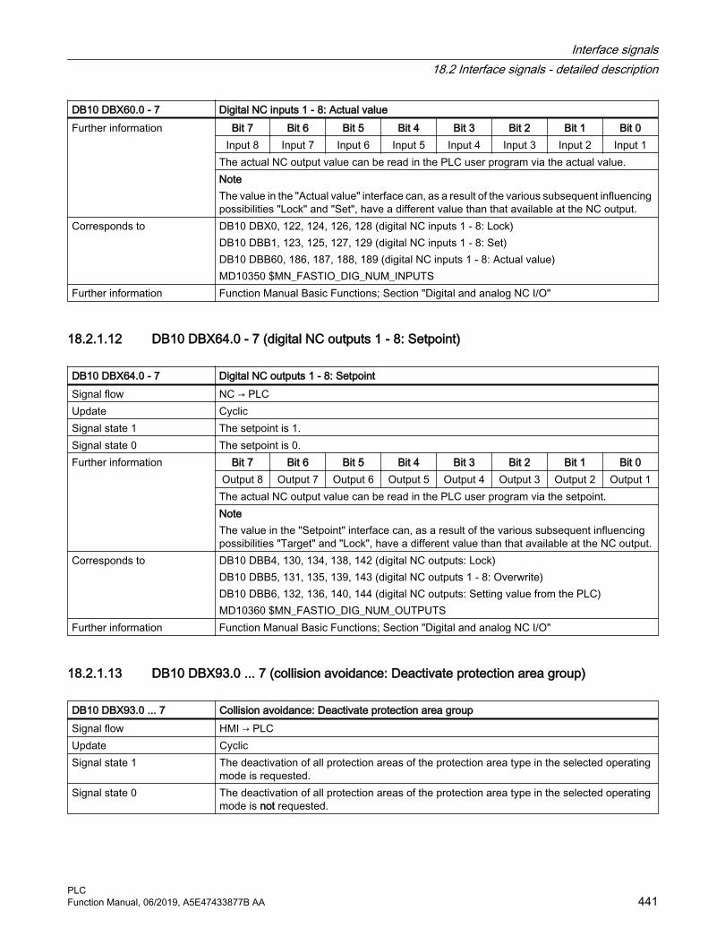
DB10 DBX60.0 - 7 Digital NC inputs 1 - 8: Actual valueFurther information Bit 7 Bit 6 Bit 5 Bit 4 Bit 3 Bit 2 Bit 1 Bit 0
Input 8 Input 7 Input 6 Input 5 Input 4 Input 3 Input 2 Input 1The actual NC output value can be read in the PLC user program via the actual value.NoteThe value in the "Actual value" interface can, as a result of the various subsequent influencing possibilities "Lock" and "Set", have a different value than that available at the NC output.
Corresponds to DB10 DBX0, 122, 124, 126, 128 (digital NC inputs 1 - 8: Lock)DB10 DBB1, 123, 125, 127, 129 (digital NC inputs 1 - 8: Set) DB10 DBB60, 186, 187, 188, 189 (digital NC inputs 1 - 8: Actual value) MD10350 $MN_FASTIO_DIG_NUM_INPUTS
Further information Function Manual Basic Functions; Section "Digital and analog NC I/O"
18.2.1.12 DB10 DBX64.0 - 7 (digital NC outputs 1 - 8: Setpoint)
DB10 DBX64.0 - 7 Digital NC outputs 1 - 8: SetpointSignal flow NC → PLCUpdate CyclicSignal state 1 The setpoint is 1.Signal state 0 The setpoint is 0.Further information Bit 7 Bit 6 Bit 5 Bit 4 Bit 3 Bit 2 Bit 1 Bit 0
Output 8 Output 7 Output 6 Output 5 Output 4 Output 3 Output 2 Output 1The actual NC output value can be read in the PLC user program via the setpoint.NoteThe value in the "Setpoint" interface can, as a result of the various subsequent influencing possibilities "Target" and "Lock", have a different value than that available at the NC output.
Corresponds to DB10 DBB4, 130, 134, 138, 142 (digital NC outputs: Lock) DB10 DBB5, 131, 135, 139, 143 (digital NC outputs 1 - 8: Overwrite)DB10 DBB6, 132, 136, 140, 144 (digital NC outputs: Setting value from the PLC) MD10360 $MN_FASTIO_DIG_NUM_OUTPUTS
Further information Function Manual Basic Functions; Section "Digital and analog NC I/O"
18.2.1.13 DB10 DBX93.0 ... 7 (collision avoidance: Deactivate protection area group)
DB10 DBX93.0 ... 7 Collision avoidance: Deactivate protection area group Signal flow HMI → PLCUpdate CyclicSignal state 1 The deactivation of all protection areas of the protection area type in the selected operating
mode is requested.Signal state 0 The deactivation of all protection areas of the protection area type in the selected operating
mode is not requested.
Interface signals18.2 Interface signals - detailed description
PLCFunction Manual, 06/2019, A5E47433877B AA 441

DB10 DBX93.0 ... 7 Collision avoidance: Deactivate protection area group Further information Bit Operating mode Protection area type 1)
0 AUTOMATIC Machine1 Tool2 Workholder3 Workpiece4 JOG Machine5 Tool6 Workholder7 Workpiece
1) Type of a protection area ($NP_PROT_TYPE)NoteThe deactivation of a protection area group is selected from the SINUMERIK Operate user interface in the operating area "AUTOMATIC", "JOG" or "MDI" > "ETC key (">")" > "Settings" > "Collision avoidance" > "Switch collision avoidance on and off" by setting the HMI/PLC interface signal DB10 DBX93.0 ... 7 of the protection area group.The interface signal is transferred according to the value of the FB1 parameter MMCToIf by the basic PLC program into the NC/PLC interface signal DB10 DBX58.0 ... 7:● "TRUE": Transmission● "FALSE": No transmissionThe default value of the parameter is "TRUE".NoteIf manual traversing has been enabled in AUTOMATIC mode (MD10735 with bit 0 == 1: allow jogging in the automatic mode) the settings for the JOG mode also apply in AUTOMATIC mode during manual traversing.
Corresponds to DB10 DBX58.0 ... 7 (collision avoidance: Deactivate protection area group)$NP_PROT_TYPE (type of protection area)MD10735 $MN_JOG_MODE_MASK (settings for the JOG mode)
Further information ● Turning and/or Milling Operating Manual; Chapter "Collision avoidance"● Function Manual Monitoring and Compensating; Section "Geometric machine modeling"
> "Commissioning" > "System variables: Protection areas" > "$NP_PROT_TYPE"● Function Manual Monitoring and Compensating; Section "Collision avoidance"
18.2.1.14 DB10 DBX97.0 - 3 (channel number geometry axis handwheel 1)
DB10 DBX97.0 - 3 Channel number for geometry axis, handwheel 1Signal flow HMI → PLCUpdate Cyclic
Interface signals18.2 Interface signals - detailed description
PLC442 Function Manual, 06/2019, A5E47433877B AA

DB10 DBX97.0 - 3 Channel number for geometry axis, handwheel 1Further information The operator can assign an axis to the handwheel (1, 2, 3) directly at the operator panel. If this
axis is a geometry axis (interface signal "Machine axis handwheel <n>" = 0), then the basic PLC program provides the corresponding channel number at the HMI interface as binary-coded value.Example:
Bit 3 Bit 2 Bit 1 Bit 0 Channel number0 0 1 0 2
NoteFor machine axes (interface signal "Machine axis handwheel <n>" = 1), interface signal "Channel number geometry axis handwheel <n>" has no significance.
Corresponds to DB10 DBX98.0 - 3 (channel number geometry axis handwheel 2)DB10 DBX99.0 - 3 (channel number geometry axis handwheel 3)DB10 DBX100.0 - 4 (axis number handwheel 1)DB10 DBX101.0 - 4 (axis number handwheel 2)DB10 DBX102.0 - 4 (axis number handwheel 3)DB10 DBX100.6 (handwheel 1 selected)DB10 DBX101.6 (handwheel 2 selected)DB10 DBX102.6 (handwheel 3 selected)DB10 DBX100.7 (machine axis handwheel 1)DB10 DBX101.7 (machine axis handwheel 2)DB10 DBX102.7 (machine axis handwheel 3)DB21, ... DBX12.0 - 2 (geometry axis 1: activate handwheel)DB21, ... DBX16.0 - 2 (geometry axis 2: activate handwheel)DB21, ... DBX20.0 - 2 (geometry axis 3: activate handwheel)DB31, ... DBX4.0 - 2 (activate handwheel)
Further information Function Manual Axes and Spindles; Section "Manual traversing"
18.2.1.15 DB10 DBX98.0 - 3 (channel number geometry axis handwheel 2)
DB10 DBX98.0 - 3 Channel number for geometry axis, handwheel 2Additional information See DB10 DBB97 (channel number geometry axis handwheel 1) (Page 442).
18.2.1.16 DB10 DBX99.0 - 3 (channel number geometry axis handwheel 3)
DB10 DBX99.0 - 3 Channel number for geometry axis, handwheel 3Additional information See DB10 DBB97 (channel number geometry axis handwheel 1) (Page 442).
Interface signals18.2 Interface signals - detailed description
PLCFunction Manual, 06/2019, A5E47433877B AA 443

18.2.1.17 DB10 DBX100.0 - 4 (axis number handwheel 1)
DB10 DBX100.0 - 4 Axis number handwheel 1Signal flow HMI → PLCUpdate CyclicFurther information The operator can assign an axis to the handwheel (1, 2, 3) directly at the operator panel. To
do this, it specifies the requested axis (e.g. X). The basic PLC program provides the axis number, associated with the axis, at the HMI interface as binary-coded value.Example:
Bit 4 Bit 3 Bit 2 Bit 1 Bit 0 Axis number0 0 1 0 1 5
The following applies when assigning the axis identifier to the axis number:● Machine axis (interface signal "Machine axis" = 1):
→ The assignment is realized using machine data MD10000.● Geometry axis (interface signal "Machine axis" = 0):
→ The assignment is realized using machine data MD20060.Corresponds to DB10 DBX101.0 - 4 (axis number handwheel 2)
DB10 DBX102.0 - 4 (axis number handwheel 3)DB10 DBX97.0 - 3 (channel number geometry axis handwheel 1)DB10 DBX98.0 - 3 (channel number geometry axis handwheel 2)DB10 DBX99.0 - 3 (channel number geometry axis handwheel 3)DB10 DBX100.6 (handwheel 1 selected)DB10 DBX101.6 (handwheel 2 selected)DB10 DBX102.6 (handwheel 3 selected)DB10 DBX100.7 (machine axis handwheel 1)DB10 DBX101.7 (machine axis handwheel 2)DB10 DBX102.7 (machine axis handwheel 3)DB21, ... DBX12.0 - 2 (geometry axis 1: activate handwheel)DB21, ... DBX16.0 - 2 (geometry axis 2: activate handwheel)DB21, ... DBX20.0 - 2 (geometry axis 3: activate handwheel)DB31, ... DBX4.0 - 2 (activate handwheel)MD10000 $MN_AXCONF_MACHAX_NAME_TAB [<n>] (machine axis name)MD20060 $MC_AXCONF_GEOAX_NAME_TAB [<n>] (name of the geometry axis in the channel)
Further information Function Manual Axes and Spindles; Section "Manual traversing"
18.2.1.18 DB10 DBX100.5 (define handwheel 1 as contour handwheel)
DB10 DBX100.5 Define handwheel 1 as contour handwheelSignal flow HMI → PLCUpdate CyclicSignal state 1 The handwheel is defined as contour handwheel via the operator interface.Signal state 0 The handwheel is not defined as contour handwheel.
Interface signals18.2 Interface signals - detailed description
PLC444 Function Manual, 06/2019, A5E47433877B AA
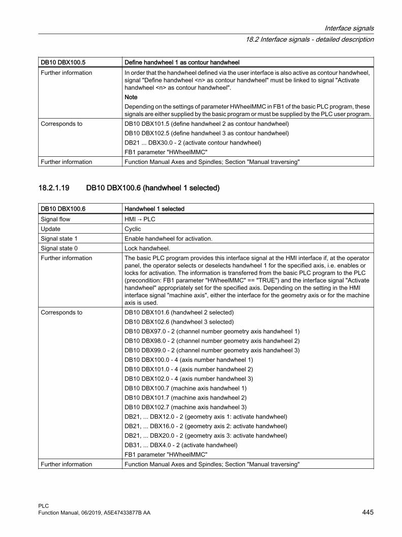
DB10 DBX100.5 Define handwheel 1 as contour handwheelFurther information In order that the handwheel defined via the user interface is also active as contour handwheel,
signal "Define handwheel <n> as contour handwheel" must be linked to signal "Activate handwheel <n> as contour handwheel".NoteDepending on the settings of parameter HWheelMMC in FB1 of the basic PLC program, these signals are either supplied by the basic program or must be supplied by the PLC user program.
Corresponds to DB10 DBX101.5 (define handwheel 2 as contour handwheel)DB10 DBX102.5 (define handwheel 3 as contour handwheel)DB21 ... DBX30.0 - 2 (activate contour handwheel)FB1 parameter "HWheelMMC"
Further information Function Manual Axes and Spindles; Section "Manual traversing"
18.2.1.19 DB10 DBX100.6 (handwheel 1 selected)
DB10 DBX100.6 Handwheel 1 selectedSignal flow HMI → PLCUpdate CyclicSignal state 1 Enable handwheel for activation.Signal state 0 Lock handwheel.Further information The basic PLC program provides this interface signal at the HMI interface if, at the operator
panel, the operator selects or deselects handwheel 1 for the specified axis, i.e. enables or locks for activation. The information is transferred from the basic PLC program to the PLC (precondition: FB1 parameter "HWheelMMC" == "TRUE") and the interface signal "Activate handwheel" appropriately set for the specified axis. Depending on the setting in the HMI interface signal "machine axis", either the interface for the geometry axis or for the machine axis is used.
Corresponds to DB10 DBX101.6 (handwheel 2 selected)DB10 DBX102.6 (handwheel 3 selected)DB10 DBX97.0 - 2 (channel number geometry axis handwheel 1)DB10 DBX98.0 - 2 (channel number geometry axis handwheel 2)DB10 DBX99.0 - 2 (channel number geometry axis handwheel 3)DB10 DBX100.0 - 4 (axis number handwheel 1)DB10 DBX101.0 - 4 (axis number handwheel 2)DB10 DBX102.0 - 4 (axis number handwheel 3)DB10 DBX100.7 (machine axis handwheel 1)DB10 DBX101.7 (machine axis handwheel 2)DB10 DBX102.7 (machine axis handwheel 3)DB21, ... DBX12.0 - 2 (geometry axis 1: activate handwheel)DB21, ... DBX16.0 - 2 (geometry axis 2: activate handwheel)DB21, ... DBX20.0 - 2 (geometry axis 3: activate handwheel)DB31, ... DBX4.0 - 2 (activate handwheel)FB1 parameter "HWheelMMC"
Further information Function Manual Axes and Spindles; Section "Manual traversing"
Interface signals18.2 Interface signals - detailed description
PLCFunction Manual, 06/2019, A5E47433877B AA 445

18.2.1.20 DB10 DBX100.7 (machine axis handwheel 1)
DB10 DBX100.7 Machine axis handwheel 1Signal flow HMI → PLCUpdate CyclicSignal state 1 Axis is a machine axis.Signal state 0 Axis is a geometry axis.Further information The basic PLC program provides this interface signal at the HMI interface if the operator has
assigned an axis to the handwheel (1, 2, 3) directly at the operator panel.Corresponds to DB10 DBX101.7 (machine axis handwheel 2)
DB10 DBX102.7 (machine axis handwheel 3)DB10 DBX97.0 - 2 (channel number geometry axis handwheel 1)DB10 DBX98.0 - 2 (channel number geometry axis handwheel 2)DB10 DBX99.0 - 2 (channel number geometry axis handwheel 3)DB10 DBX100.0 - 4 (axis number handwheel 1)DB10 DBX101.0 - 4 (axis number handwheel 2)DB10 DBX102.0 - 4 (axis number handwheel 3)DB10 DBX100.6 (handwheel 1 selected)DB10 DBX101.6 (handwheel 2 selected)DB10 DBX102.6 (handwheel 3 selected)
Further information Function Manual Axes and Spindles; Section "Manual traversing"
18.2.1.21 DB10 DBX101.0 - 4 (axis number handwheel 2)
DB10 DBX101.0 - 4 Axis number handwheel 2Additional information See DB10 DBX100.0 - 4 (axis number handwheel 1) (Page 444).
18.2.1.22 DB10 DBX101.5 (define handwheel 2 as contour handwheel)
DB10 DBX101.5 Define handwheel 2 as contour handwheelAdditional information See DB10 DBX100.5 (define handwheel 1 as contour handwheel) (Page 444).
18.2.1.23 DB10 DBX101.6 (handwheel 2 selected)
DB10 DBX101.6 Handwheel 2 selectedAdditional information See DB10 DBX100.6 (handwheel 1 selected) (Page 445).
Interface signals18.2 Interface signals - detailed description
PLC446 Function Manual, 06/2019, A5E47433877B AA

18.2.1.24 DB10 DBX101.7 (machine axis handwheel 2)
DB10 DBX101.7 Machine axis handwheel 2Additional information See DB10 DBX100.7 (machine axis handwheel 1) (Page 446).
18.2.1.25 DB10 DBX102.0 - 4 (axis number handwheel 3)
DB10 DBX102.0 - 4 Axis number handwheel 3Additional information See DB10 DBX100.0 - 4 (axis number handwheel 1) (Page 444).
18.2.1.26 DB10 DBX102.5 (define handwheel 3 as contour handwheel)
DB10 DBX102.5 Define handwheel 3 as contour handwheelAdditional information See DB10 DBX100.5 (define handwheel 1 as contour handwheel) (Page 444).
18.2.1.27 DB10 DBX102.6 (handwheel 3 selected)
DB10 DBX102.6 Handwheel 3 selectedAdditional information See DB10 DBX100.6 (handwheel 1 selected) (Page 445).
18.2.1.28 DB10 DBX102.7 (machine axis handwheel 3)
DB10 DBX102.7 Machine axis handwheel 3Additional information See DB10 DBX100.7 (machine axis handwheel 1) (Page 446).
18.2.1.29 DB10 DBX103.0 (remote diagnosis active)
DB10 DBX103.0 Remote diagnosis activeSignal flow HMI → PLC Update CyclicallySignal state 1 Remote diagnosis (optional) is active, i.e. the control is operated via an external PC.Signal state 0 Remote diagnosis is not active.
18.2.1.30 DB10 DBX103.5 (AT box ready)
DB10 DBX103.5 AT box readySignal flow HMI → PLC Update Cyclically
Interface signals18.2 Interface signals - detailed description
PLCFunction Manual, 06/2019, A5E47433877B AA 447

DB10 DBX103.5 AT box readySignal state 1 The AT box for expansion modules is ready.Signal state 0 The AT box is not ready. An expansion module conforming to the AT specification has either
no functionality or restricted functionality.
18.2.1.31 DB10 DBX103.6 (HMI temperature limit)
DB10 DBX103.6 HMI temperature limitSignal flow HMI → PLC Update CyclicallySignal state 1 The temperature is within the permissible tolerance range from 5 to 55 °C.Signal state 0 The temperature is outside the permissible tolerance range from 5 to 55 °C.
The temperature monitoring has responded and the PCU has been disabled.
18.2.1.32 DB10 DBX103.7 (HMI battery alarm)
DB10 DBX103.7 HMI battery alarmSignal flow HMI → PLCUpdate CyclicSignal state 1 The battery monitor has responded. Power failure can cause the loss of recently changed data
and a correct device configuration. An appropriate alarm is issued. The buffer battery should be checked. An insufficient battery voltage also affects the current time on the user interface.
Signal state 0 No HMI battery alarm is present.Further information Operator Components Manual (PCU)
18.2.1.33 DB10 DBX104.7 (NC-CPU ready)
DB10 DBX104.7 NC CPU ready Signal flow NC → PLCUpdate CyclicSignal state 1 The NC CPU is ready and registers itself cyclically with the PLC.
After a correct initial start and the first complete OB1 cycle, the PLC and NC continuously exchange sign-of-life signals.
Signal state 0 NC CPU is not ready for operation.The following measures are started by the basic PLC program:● The status signals of the NC to the PLC (user interface) are deleted● The change signals of auxiliary functions are deleted● Cyclic processing of the user interface PLC to NC is terminated.
Further information ● Diagnostics Manual
Interface signals18.2 Interface signals - detailed description
PLC448 Function Manual, 06/2019, A5E47433877B AA

18.2.1.34 DB10 DBX106.1 (Emergency Stop active)
DB10 DBX106.1 Emergency Stop activeSignal flow NC → PLCUpdate CyclicSignal state 1 Emergency Stop is active.Signal state 0 Emergency Stop is not active.Further information To acknowledge the "Emergency Stop" state of the NC, the following interface signals must
remain set until interface signal DB10 DBX106.1 (Emergency Stop active) has been reset:● DB10 DBX56.2 = 1 (acknowledge Emergency Stop)● DB11, ... DBX0.7 = 1 (mode group reset) for all mode groups of the NC
Corresponds to DB10 DBX56.1 (Emergency Stop)DB10 DBX56.2 (acknowledge Emergency Stop)DB11 DBX0.7 (mode group reset)
Further information Function Manual Basic Functions; Section "Emergency stop"
18.2.1.35 DB10 DBX107.0 - 1 (probe actuated)
DB10 DBX107.0 - 1 Probe actuatedSignal flow NC → PLCUpdate CyclicSignal state 1 Probe deflected.Signal state 0 Probe not deflected.Further information Bit 0 Probe 1
Bit 1 Probe 2Further information Function Manual Technologies; Section "Measuring"
18.2.1.36 DB10 DBX107.6 (NCU link active)
DB10 DBX107.6 NCU link: ActiveSignal flow NC → PLCUpdate CyclicSignal state 1 NCU link communication is active.Signal state 0 NCU link communication is not active.Further information The signal is irrelevant for a system with an NCU.Further information ● Function Manual Basic Functions; Section "Distributed systems"
● NCU Equipment Manual
Interface signals18.2 Interface signals - detailed description
PLCFunction Manual, 06/2019, A5E47433877B AA 449

18.2.1.37 DB10 DBX108.3 (operating software ready)
DB10 DBX108.3 Operating software readySignal flow NC → PLCUpdate CyclicSignal state 1 SINUMERIK Operate is ready and registers itself cyclically with the NC.Signal state 0 SINUMERIK Operate is not ready.Further information Diagnostics Manual
18.2.1.38 DB10 DBX108.5 (drives in cyclic operation)
DB10 DBX108.5 Drives in cyclic operationSignal flow NC → PLCUpdate CyclicallySignal state 1 For all machine axes of the NC, the corresponding drives are in cyclic operation, i.e. they
cyclically exchange PROFIdrive telegrams with the NC.Signal state 0 For at least one machine axis of the NC, the corresponding drive is not in cyclic operation, i.e.
it is not cyclically exchanging PROFIdrive telegrams with the NC.
18.2.1.39 DB10 DBX108.6 (drive ready)
DB10 DBX108.6 Drive readySignal flow NC → PLCUpdate CyclicallySignal state 1 For all machine axes of the NC, the corresponding drives are ready:
DB31, ... DBX93.5 == 1 (DRIVE ready)Signal state 0 For at least one machine axis of the NC, the corresponding drive is not ready:
DB31, ... DBX93.5 == 0 (DRIVE ready)Corresponds with DB31, ... DBX93.5 (DRIVE ready)
18.2.1.40 DB10 DBX108.7 (NC ready)
DB10 DBX108.7 NC readySignal flow NC → PLCUpdate CyclicSignal state 1 The control is ready.
The interface signal is an image of the relay contact "NC Ready".The signal is set when:● Relay contact "NC Ready": closed● All internal control voltages have been established● Control state: Cyclic operation
Interface signals18.2 Interface signals - detailed description
PLC450 Function Manual, 06/2019, A5E47433877B AA

DB10 DBX108.7 NC readySignal state 0 The control is not ready.
The signal is set when:● Relay contact "NC Ready": openPossible causes:● The undervoltage or overvoltage monitoring function has responded● Individual components are not ready (NC CPU ready)● The NC CPU watchdog has respondedIf still possible, the following internal control responses occur:● NC: The controller enable signals are withdrawn ⇒ the drives stop● PLC basic program:
– The status signals from the NC to the PLC (user interface) are deleted– The change signals of the auxiliary functions are deleted– Cyclic processing of the user interface PLC to NC is terminated
Remedy:A warm restart must be initiated to exit the fault state.
Corresponds to DB10 DBX104.7(NC CPU ready)Further information Diagnostics Manual
18.2.1.41 DB10 DBX109.0 (NC alarm active)
DB10 DBX109.0 NC alarm is activeSignal flow NC → PLCUpdate CyclicSignal state 1 At least one NC alarm is active.Signal state 0 No NC alarm is active.Further information The interface signal is a combination of interface signals of all of the existing channels:
DB21, ... DBX36.6 (channel-specific NC alarm active)Corresponds to DB21, ... DBX36.6 (channel-specific NC alarm active)
DB21, ... DBX36.7 (NC alarm with machining stop active)Further information Diagnostics Manual
18.2.1.42 DB10 DBX109.5 (heat sink temperature alarm, NCU)
DB10 DBX109.5 NCU heat sink temperature alarmSignal flow NC → PLCUpdate CyclicallySignal state 1 The heat sink temperature limit of the NCU has been exceeded. Continuous NCU operation
can no longer be guaranteed.Signal state 0 The heat sink temperature limit of the NCU has not been exceeded.
Interface signals18.2 Interface signals - detailed description
PLCFunction Manual, 06/2019, A5E47433877B AA 451

18.2.1.43 DB10 DBX109.6 (air temperature alarm)
DB10 DBX109.6 Air temperature alarmSignal flow NC → PLCUpdate CyclicSignal state 1 The monitoring of the ambient temperature and/or the fan monitoring has responded.
Possible causes:● Ambient temperature too high● The speed monitoring of the 24 VDC fan used to cool the module has responded.Possible remedy: Replace the fan and/or ensure that additional ventilation/cooling is provided.
Signal state 0 The monitoring of the ambient temperature and the fan monitoring has not responded.Corresponds to Relay contacts of the infeed/regenerative feedback unit: Terminal 5.1, 5.2 or 5.1, 5.3)Further information Diagnostics Manual
18.2.1.44 DB10 DBX109.7 (NC battery alarm)
DB10 DBX109.7 NC battery alarmSignal flow NC → PLCUpdate CyclicSignal state 1 The NC battery voltage monitoring function has responded.
This may be due to the following causes:● The battery voltage is within the pre-warning limit range (approx. 2.7 to 2.9 V).● The battery voltage is below the pre-warning limit range (≤ 2.6 V).● When the controller powered-up, it was identified that the battery voltage was below the
pre-warning limit range (≤ 2.6 V).Signal state 0 The battery voltage is higher than the lower limit value (normal situation).Further information The NC battery should only be replaced while the NC is switched on to avoid data loss as there
is no memory backup.Further information ● Diagnostics Manual
● NCU Equipment Manual
18.2.1.45 DB10 DBX110.0 - 113.7 (software cams: minus cam signal 1 to 32)
DB10 DBX110.0 - 113.7 Software cams: minus cam signal 1 to 32Signal flow NC → PLCUpdate CyclicSignal state 1 Linear axis
The minus cam signal switches from 0 to 1 when the axis passes over the minus cam in the negative direction.Modulo rotary axisThe minus cam signal changes level in response to every positive edge of the plus cam signal.
Interface signals18.2 Interface signals - detailed description
PLC452 Function Manual, 06/2019, A5E47433877B AA

DB10 DBX110.0 - 113.7 Software cams: minus cam signal 1 to 32Signal state 0 Linear axis
The minus cam signal switches from 1 to 0 when the axis passes over the minus cam in the positive axis direction.Modulo rotary axisThe minus cam signal changes level in response to every positive edge of the plus cam signal.
Additional information The switching edge of the minus cam signal 1 to 32 is generated depending on the traversing direction of the (round) axis, and is transferred in the IPO clock cycle to the PLC interface.
Corresponds with DB10 DBX114.0 - 117.7 (software cams: plus cam signal 1 to 32)DB31, ... DBX2.0 (software cams: activation)
Additional references Function Manual, Extended Functions; Chapter "N3: software cams, position switching sig‐nals"
18.2.1.46 DB10 DBX114.0 - 117.7 (software cams: plus cam signal 1 to 32)
DB10 DBX114.0 - 117.7 Software cams: plus cam signal 1 to 32Signal flow NC → PLCUpdate CyclicSignal state 1 Linear axis
The plus cam signal switches from 0 to 1 when the axis traverses the plus cam in the positive direction.Modulo rotary axisWhen passing over the minus cam in the positive axis direction, the plus cam signal switches from 0 to 1.
Signal state 0 Linear axisThe plus cam signal switches from 1 to 0 when the axis traverses the plus cam in the negative direction.Modulo rotary axisWhen passing over the plus cam in the positive axis direction, the plus cam signal switches back from 1 to 0.
Further information The switching edge of the plus cam signal 1 to 32 is generated depending on the traversing direction of the (round) axis, and is transferred in the IPO clock cycle to the PLC interface.NoteThe described response of the plus cam for modulo rotary axes applies under the condition:plus cam - minus cam < 180 degreesIf this condition is not fulfilled or if the minus cam is set to a greater value than the plus cam, then the behavior of the plus cam signal is inverted. The response of the minus cam signal remains unchanged.
Corresponds to DB10 DBX110.0 - 113.7 (software cams: minus cam signal 1 to 32)DB31, ... DBX2.0 (software cams: activation)
Further information Function Manual Axes and Spindles; Section Software cams, position switching signals
Interface signals18.2 Interface signals - detailed description
PLCFunction Manual, 06/2019, A5E47433877B AA 453

18.2.1.47 DB10 DBX122.0 - 7 (digital NC inputs 9 - 16: Lock)
DB10 DBX122.0 - 7 Digital NC inputs 9 - 16: LockSignal flow PLC → NCUpdate CyclicSignal state 1 The digital NC input is locked.Signal state 0 The digital NC input is enabled. Further information Bit 7 Bit 6 Bit 5 Bit 4 Bit 3 Bit 2 Bit 1 Bit 0
Input 16 Input 15 Input 14 Input 13 Input 12 Input 11 Input 10 Input 9NoteWhen read, a locked input supplies a value of 0.
Corresponds to DB10 DBB1, 123, 125, 127, 129 (digital NC inputs set from the PLC) DB10 DBB60, 186, 187, 188, 189 (actual value of the digital NC inputs) MD10350 $MN_FASTIO_DIG_NUM_INPUTS
Further information Function Manual Basic Functions; Section "Digital and analog NC I/O" > "Indirect I/O access‐es via PLC" > "Digital NC inputs/outputs" > "NC inputs"
18.2.1.48 DB10 DBX123.0 - 7 (digital NC inputs 9 - 16: Set)
DB10 DBX123.0 - 7 Digital NC inputs 9 - 16: Set Signal flow PLC → NCUpdate CyclicSignal state 1 Set NC input value to a defined value of 1.Signal state 0 Do not influence NC input value.Further information Bit 7 Bit 6 Bit 5 Bit 4 Bit 3 Bit 2 Bit 1 Bit 0
Input 16 Input 15 Input 14 Input 13 Input 12 Input 11 Input 10 Input 9If the PLC user program sets the NC input to a value of 1, then the signal state at the onboard input of the NCU - as well as the lock of the NC input - have no effect.
Corresponds to DB10 DBX0, 122, 124, 126, 128 (digital NC inputs 1 - 8: Lock)DB10 DBB1, 123, 125, 127, 129 (digital NC inputs 1 - 8: Set) DB10 DBB60, 186, 187, 188, 189 (digital NC inputs 1 - 8: Actual value) MD10350 $MN_FASTIO_DIG_NUM_INPUTS
Further information Function Manual Basic Functions; Section "Digital and analog NC I/O" > "Indirect I/O access‐es via PLC" > "Digital NC inputs/outputs" > "NC inputs"
18.2.1.49 DB10 DBX124.0 - 7 (digital NC inputs 17 - 24: Lock)
DB10 DBX124.0 - 7 Digital NC inputs 17 - 24: LockSignal flow PLC → NCUpdate CyclicSignal state 1 The digital NC input is locked.Signal state 0 The digital NC input is enabled.
Interface signals18.2 Interface signals - detailed description
PLC454 Function Manual, 06/2019, A5E47433877B AA

DB10 DBX124.0 - 7 Digital NC inputs 17 - 24: LockFurther information Bit 7 Bit 6 Bit 5 Bit 4 Bit 3 Bit 2 Bit 1 Bit 0
Input 24 Input 23 Input 22 Input 21 Input 20 Input 19 Input 18 Input 17NoteWhen read, a locked input supplies a value of 0.
Corresponds to DB10 DBB1, 123, 125, 127, 129 (digital NC inputs set from the PLC) DB10 DBB60, 186, 187, 188, 189 (actual value of the digital NC inputs) MD10350 $MN_FASTIO_DIG_NUM_INPUTS
Further information Function Manual Basic Functions; Section "Digital and analog NC I/O" > "Indirect I/O access‐es via PLC" > "Digital NC inputs/outputs" > "NC inputs"
18.2.1.50 DB10 DBX125.0 - 7 (digital NC inputs 17 - 24: Set)
DB10 DBX125.0 - 7 Digital NC inputs 17 - 24: Set Signal flow PLC → NCUpdate CyclicSignal state 1 Set NC input value to a defined value of 1.Signal state 0 Do not influence NC input value.Further information Bit 7 Bit 6 Bit 5 Bit 4 Bit 3 Bit 2 Bit 1 Bit 0
Input 24 Input 23 Input 22 Input 21 Input 20 Input 19 Input 18 Input 17If the PLC user program sets the NC input to a value of 1, then the signal state at the onboard input of the NCU - as well as the lock of the NC input - have no effect.
Corresponds to DB10 DBX0, 122, 124, 126, 128 (digital NC inputs 1 - 8: Lock)DB10 DBB1, 123, 125, 127, 129 (digital NC inputs 1 - 8: Set) DB10 DBB60, 186, 187, 188, 189 (digital NC inputs 1 - 8: Actual value) MD10350 $MN_FASTIO_DIG_NUM_INPUTS
Further information Function Manual Basic Functions; Section "Digital and analog NC I/O" > "Indirect I/O access‐es via PLC" > "Digital NC inputs/outputs" > "NC inputs"
18.2.1.51 DB10 DBX126.0 - 7 (digital NC inputs 25 - 32: Lock)
DB10 DBX126.0 - 7 Digital NC inputs 25 - 32: LockSignal flow PLC → NCUpdate CyclicSignal state 1 The digital NC input is locked.Signal state 0 The digital NC input is enabled. Further information Bit 7 Bit 6 Bit 5 Bit 4 Bit 3 Bit 2 Bit 1 Bit 0
Input 32 Input 31 Input 30 Input 29 Input 28 Input 27 Input 26 Input 25NoteWhen read, a locked input supplies a value of 0.
Interface signals18.2 Interface signals - detailed description
PLCFunction Manual, 06/2019, A5E47433877B AA 455

DB10 DBX126.0 - 7 Digital NC inputs 25 - 32: LockCorresponds to DB10 DBB1, 123, 125, 127, 129 (digital NC inputs set from the PLC)
DB10 DBB60, 186, 187, 188, 189 (actual value of the digital NC inputs) MD10350 $MN_FASTIO_DIG_NUM_INPUTS
Further information Function Manual Basic Functions; Section "Digital and analog NC I/O" > "Indirect I/O access‐es via PLC" > "Digital NC inputs/outputs" > "NC inputs"
18.2.1.52 DB10 DBX127.0 - 7 (digital NC inputs 25 - 32: Set)
DB10 DBX127.0 - 7 Digital NC inputs 25 - 32: Set Signal flow PLC → NCUpdate CyclicSignal state 1 Set NC input value to a defined value of 1.Signal state 0 Do not influence NC input value.Further information Bit 7 Bit 6 Bit 5 Bit 4 Bit 3 Bit 2 Bit 1 Bit 0
Input 32 Input 31 Input 30 Input 29 Input 28 Input 27 Input 26 Input 25If the PLC user program sets the NC input to a value of 1, then the signal state at the onboard input of the NCU - as well as the lock of the NC input - have no effect.
Corresponds to DB10 DBX0, 122, 124, 126, 128 (digital NC inputs 1 - 8: Lock)DB10 DBB1, 123, 125, 127, 129 (digital NC inputs 1 - 8: Set) DB10 DBB60, 186, 187, 188, 189 (digital NC inputs 1 - 8: Actual value) MD10350 $MN_FASTIO_DIG_NUM_INPUTS
Further information Function Manual Basic Functions; Section "Digital and analog NC I/O" > "Indirect I/O access‐es via PLC" > "Digital NC inputs/outputs" > "NC inputs"
18.2.1.53 DB10 DBX128.0 - 7 (digital NC inputs 33 - 40: Lock)
DB10 DBX128.0 - 7 Digital NC inputs 33 - 40: LockSignal flow PLC → NCUpdate CyclicSignal state 1 The digital NC input is locked.Signal state 0 The digital NC input is enabled. Further information Bit 7 Bit 6 Bit 5 Bit 4 Bit 3 Bit 2 Bit 1 Bit 0
Input 40 Input 39 Input 38 Input 37 Input 36 Input 35 Input 34 Input 33NoteWhen read, a locked input supplies a value of 0.
Corresponds to DB10 DBB1, 123, 125, 127, 129 (digital NC inputs set from the PLC) DB10 DBB60, 186, 187, 188, 189 (actual value of the digital NC inputs) MD10350 $MN_FASTIO_DIG_NUM_INPUTS
Further information Function Manual Basic Functions; Section "Digital and analog NC I/O" > "Indirect I/O access‐es via PLC" > "Digital NC inputs/outputs" > "NC inputs"
Interface signals18.2 Interface signals - detailed description
PLC456 Function Manual, 06/2019, A5E47433877B AA

18.2.1.54 DB10 DBX129.0 - 7 (digital NC inputs 33 - 40: Set)
DB10 DBX129.0 - 7 Digital NC inputs 33 - 40: SetSignal flow PLC → NCUpdate CyclicSignal state 1 Set NC input value to a defined value of 1.Signal state 0 Do not influence NC input value.Further information Bit 7 Bit 6 Bit 5 Bit 4 Bit 3 Bit 2 Bit 1 Bit 0
Input 40 Input 39 Input 38 Input 37 Input 36 Input 35 Input 34 Input 33If the PLC user program sets the NC input to a value of 1, then the signal state at the onboard input of the NCU - as well as the lock of the NC input - have no effect.
Corresponds to DB10 DBX0, 122, 124, 126, 128 (digital NC inputs 1 - 8: Lock)DB10 DBB1, 123, 125, 127, 129 (digital NC inputs 1 - 8: Set) DB10 DBB60, 186, 187, 188, 189 (digital NC inputs 1 - 8: Actual value) MD10350 $MN_FASTIO_DIG_NUM_INPUTS
Further information Function Manual Basic Functions; Section "Digital and analog NC I/O" > "Indirect I/O access‐es via PLC" > "Digital NC inputs/outputs" > "NC inputs"
18.2.1.55 DB10 DBX130.0 - 7 (digital NC outputs 9 - 16: Lock)
DB10 DBX130.0 - 7 Digital NC outputs 9 - 16: Lock Signal flow PLC → NCUpdate CyclicSignal state 1 The digital NC output is locked.Signal state 0 The digital NC output is enabled.Additional information Bit 7 Bit 6 Bit 5 Bit 4 Bit 3 Bit 2 Bit 1 Bit 0
Output 16 Output 15 Output 14 Output 13 Output 12 Output 11 Output 10 Output 9If the digital NC output is locked, then 0 V (defined) is output at the hardware output.If the digital NC output is not locked, then the value specified in the NC program or by the PLC program is output at the hardware output.
Corresponds with DB10 DBB5, 131, 135, 139, 143 (digital NC outputs 1 - 8: Overwrite screen form) DB10 DBB6, 132, 136, 140, 144 (digital NC outputs: Setting value from the PLC) DB10 DBB7, 133, 137, 141, 145 (digital NC outputs: Target screen form) MD10360 $MN_FASTIO_DIG_NUM_OUTPUTS
Additional references Function Manual Expansion Functions; Chapter "A4: Digital and analog NC I/O" > "Indirect I/O accesses via PLC" > "Digital NC inputs/outputs" > "NC outputs"
18.2.1.56 DB10 DBX131.0 - 7 (digital NC outputs 9 - 16: Overwrite)
DB10 DBX131.0 - 7 Digital NC outputs 9 - 16: Overwrite Signal flow PLC → NCUpdate CyclicEdge change 0 → 1 The associated "setting value" is activated.
Interface signals18.2 Interface signals - detailed description
PLCFunction Manual, 06/2019, A5E47433877B AA 457

DB10 DBX131.0 - 7 Digital NC outputs 9 - 16: Overwrite Edge change 1 → 0 No effect.Further information Bit 7 Bit 6 Bit 5 Bit 4 Bit 3 Bit 2 Bit 1 Bit 0
Output 16 Output 15 Output 14 Output 13 Output 12 Output 11 Output 10 Output 9For a positive edge change 0 → 1, then for the corresponding output, instead of the value written using system variables $A_OUT, the setting value specified from the PLC user pro‐gram is used. The value written via system variables $A_OUT is then lost. For a negative edge change 1 → 0, for the corresponding output, the actual value at the hardware output is kept.NoteThe NC/PLC interface DBB6, ... (Digital NC outputs: setting value) is jointly used by:● DB10 DBB5, ... (overwrite) for edge change 0 → 1● DB10 DBB7, ... (target) for signal state 1Activating the two interfaces simultaneously should be avoided.
Corresponds to DB10 DBB4, 130, 134, 138, 142 (digital NC outputs: Lock) DB10 DBB5, 131, 135, 139, 143 (digital NC outputs 1 - 8: Overwrite)DB10 DBB6, 132, 136, 140, 144 (digital NC outputs: Setting value from the PLC) MD10360 $MN_FASTIO_DIG_NUM_OUTPUTS
Further information Function Manual Basic Functions; Section "Digital and analog NC I/O"
18.2.1.57 DB10 DBX132.0 - 7 (digital NC outputs 9 - 16: Setting value)
DB10 DBX132.0 - 7 Digital NC outputs 9 - 16: Setting value Signal flow PLC → NCUpdate CyclicSignal state 1 Value of the setting value is 1.Signal state 0 Value of the setting value is 0.Further information Bit 7 Bit 6 Bit 5 Bit 4 Bit 3 Bit 2 Bit 1 Bit 0
Output 16 Output 15 Output 14 Output 13 Output 12 Output 11 Output 10 Output 9Using the setting value, the PLC user program can specify a defined output value. In order that the setting value becomes active, it must be activated from the overwrite screen form or the setting screen form.NoteThe NC/PLC interface DBB6, ... (Digital NC outputs: setting value) is jointly used by:● DB10 DBB5, ... (overwrite) for edge change 0 → 1● DB10 DBB7, ... (target) for signal state 1Activating the two interfaces simultaneously should be avoided.
Corresponds to DB10 DBB4, 130, 134, 138, 142 (digital NC outputs: Lock) DB10 DBB5, 131, 135, 139, 143 (digital NC outputs 1 - 8: Overwrite)DB10 DBB6, 132, 136, 140, 144 (digital NC outputs: Setting value from the PLC) MD10360 $MN_FASTIO_DIG_NUM_OUTPUTS
Further information Function Manual Basic Functions; Section "Digital and analog NC I/O" > "Indirect I/O access‐es via PLC" > "Digital NC inputs/outputs" > "NC outputs"
Interface signals18.2 Interface signals - detailed description
PLC458 Function Manual, 06/2019, A5E47433877B AA

18.2.1.58 DB10 DBX133.0 - 7 (digital NC outputs 9 - 16: Target)
DB10 DBX133.0 - 7 Digital NC outputs 9 - 16: Target Signal flow PLC → NCUpdate CyclicSignal state 1 The target is active.Signal state 0 The target is not active.Further information Bit 7 Bit 6 Bit 5 Bit 4 Bit 3 Bit 2 Bit 1 Bit 0
Output 16 Output 15 Output 14 Output 13 Output 12 Output 11 Output 10 Output 9If a bit is set, then for the corresponding output, instead of the NC output value, the setting value specified by the PLC user program is used. The actual NC output value is kept. If a bit is reset, then for the corresponding output, the last NC output value becomes active again.NoteThe NC/PLC interface DBB6, ... (Digital NC outputs: setting value) is jointly used by:● DB10 DBB5, ... (overwrite) for edge change 0 → 1● DB10 DBB7, ... (target) for signal state 1Activating the two interfaces simultaneously should be avoided.
Corresponds to DB10 DBB4, 130, 134, 138, 142 (digital NC outputs: Lock) DB10 DBB5, 131, 135, 139, 143 (digital NC outputs 1 - 8: Overwrite)DB10 DBB6, 132, 136, 140, 144 (digital NC outputs: Setting value from the PLC) MD10360 $MN_FASTIO_DIG_NUM_OUTPUTS
Further information Function Manual Basic Functions; Section "Digital and analog NC I/O" > "Indirect I/O access‐es via PLC" > "Digital NC inputs/outputs" > "NC outputs"
18.2.1.59 DB10 DBX134.0 - 7 (digital NC outputs 17 - 24: Lock)
DB10 DBX134.0 - 7 Digital NC outputs 17 - 24: Lock Signal flow PLC → NCUpdate CyclicSignal state 1 The digital NC output is locked.Signal state 0 The digital NC output is enabled.Further information Bit 7 Bit 6 Bit 5 Bit 4 Bit 3 Bit 2 Bit 1 Bit 0
Output 24 Output 23 Output 22 Output 21 Output 20 Output 19 Output 18 Output 17If the digital NC output is locked, then 0 V (defined) is output at the hardware output.If the digital NC output is not locked, then the value specified in the NC program or by the PLC program is output at the hardware output.
Corresponds to DB10 DBB5, 131, 135, 139, 143 (digital NC outputs 1 - 8: Overwrite screen form) DB10 DBB6, 132, 136, 140, 144 (digital NC outputs: Setting value from the PLC) DB10 DBB7, 133, 137, 141, 145 (digital NC outputs: Target screen form) MD10360 $MN_FASTIO_DIG_NUM_OUTPUTS
Further information Function Manual Basic Functions; Section "Digital and analog NC I/O" > "Indirect I/O access‐es via PLC" > "Digital NC inputs/outputs" > "NC outputs"
Interface signals18.2 Interface signals - detailed description
PLCFunction Manual, 06/2019, A5E47433877B AA 459

18.2.1.60 DB10 DBX135.0 - 7 (digital NC outputs 17 - 24: Overwrite)
DB10 DBX135.0 - 7 Digital NC outputs 17 - 24: Overwrite Signal flow PLC → NCUpdate CyclicEdge change 0 → 1 The associated "setting value" is activated.Edge change 1 → 0 No effect.Further information Bit 7 Bit 6 Bit 5 Bit 4 Bit 3 Bit 2 Bit 1 Bit 0
Output 24 Output 23 Output 22 Output 21 Output 20 Output 19 Output 18 Output 17For a positive edge change 0 → 1, then for the corresponding output, instead of the value written using system variables $A_OUT, the setting value specified from the PLC user pro‐gram is used. The value written via system variables $A_OUT is then lost. For a negative edge change 1 → 0, for the corresponding output, the actual value at the hardware output is kept.NoteThe NC/PLC interface DBB6, ... (Digital NC outputs: setting value) is jointly used by:● DB10 DBB5, ... (overwrite) for edge change 0 → 1● DB10 DBB7, ... (target) for signal state 1Activating the two interfaces simultaneously should be avoided.
Corresponds to DB10 DBB4, 130, 134, 138, 142 (digital NC outputs: Lock) DB10 DBB5, 131, 135, 139, 143 (digital NC outputs 1 - 8: Overwrite)DB10 DBB6, 132, 136, 140, 144 (digital NC outputs: Setting value from the PLC) MD10360 $MN_FASTIO_DIG_NUM_OUTPUTS
Further information Function Manual Basic Functions; Section "Digital and analog NC I/O"
18.2.1.61 DB10 DBX136.0 - 7 (digital NC outputs 17 - 24: Setting value)
DB10 DBX136.0 - 7 Digital NC outputs 17 - 24: Setting valueSignal flow PLC → NCUpdate CyclicSignal state 1 Value of the setting value is 1.Signal state 0 Value of the setting value is 0.Further information Bit 7 Bit 6 Bit 5 Bit 4 Bit 3 Bit 2 Bit 1 Bit 0
Output 24 Output 23 Output 22 Output 21 Output 20 Output 19 Output 18 Output 17Using the setting value, the PLC user program can specify a defined output value. In order that the setting value becomes active, it must be activated from the overwrite screen form or the setting screen form.NoteThe NC/PLC interface DBB6, ... (Digital NC outputs: setting value) is jointly used by:● DB10 DBB5, ... (overwrite) for edge change 0 → 1● DB10 DBB7, ... (target) for signal state 1Activating the two interfaces simultaneously should be avoided.
Interface signals18.2 Interface signals - detailed description
PLC460 Function Manual, 06/2019, A5E47433877B AA

DB10 DBX136.0 - 7 Digital NC outputs 17 - 24: Setting valueCorresponds to DB10 DBB4, 130, 134, 138, 142 (digital NC outputs: Lock)
DB10 DBB5, 131, 135, 139, 143 (digital NC outputs 1 - 8: Overwrite)DB10 DBB6, 132, 136, 140, 144 (digital NC outputs: Setting value from the PLC) MD10360 $MN_FASTIO_DIG_NUM_OUTPUTS
Further information Function Manual Basic Functions; Section "Digital and analog NC I/O" > "Indirect I/O access‐es via PLC" > "Digital NC inputs/outputs" > "NC outputs"
18.2.1.62 DB10 DBX137.0 - 7 (digital NC outputs 17 - 24: Target)
DB10 DBX137.0 - 7 Digital NC outputs 17 - 24: Target Signal flow PLC → NCUpdate CyclicSignal state 1 The target is active.Signal state 0 The target is not active.Further information Bit 7 Bit 6 Bit 5 Bit 4 Bit 3 Bit 2 Bit 1 Bit 0
Output 24 Output 23 Output 22 Output 21 Output 20 Output 19 Output 18 Output 17If a bit is set, then for the corresponding output, instead of the NC output value, the setting value specified by the PLC user program is used. The actual NC output value is kept. If a bit is reset, then for the corresponding output, the last NC output value becomes active again.NoteThe NC/PLC interface DBB6, ... (Digital NC outputs: setting value) is jointly used by:● DB10 DBB5, ... (overwrite) for edge change 0 → 1● DB10 DBB7, ... (target) for signal state 1Activating the two interfaces simultaneously should be avoided.
Corresponds to DB10 DBB4, 130, 134, 138, 142 (digital NC outputs: Lock) DB10 DBB5, 131, 135, 139, 143 (digital NC outputs 1 - 8: Overwrite)DB10 DBB6, 132, 136, 140, 144 (digital NC outputs: Setting value from the PLC) MD10360 $MN_FASTIO_DIG_NUM_OUTPUTS
Further information Function Manual Basic Functions; Section "Digital and analog NC I/O" > "Indirect I/O access‐es via PLC" > "Digital NC inputs/outputs" > "NC outputs"
18.2.1.63 DB10 DBX138.0 - 7 (digital NC outputs 25 - 32: Lock)
DB10 DBX138.0 - 7 Digital NC outputs 25 - 32: Lock Signal flow PLC → NCUpdate CyclicSignal state 1 The digital NC output is locked.Signal state 0 The digital NC output is enabled.
Interface signals18.2 Interface signals - detailed description
PLCFunction Manual, 06/2019, A5E47433877B AA 461

DB10 DBX138.0 - 7 Digital NC outputs 25 - 32: Lock Further information Bit 7 Bit 6 Bit 5 Bit 4 Bit 3 Bit 2 Bit 1 Bit 0
Output 32 Output 31 Output 30 Output 29 Output 28 Output 27 Output 26 Output 25If the digital NC output is locked, then 0 V (defined) is output at the hardware output.If the digital NC output is not locked, then the value specified in the NC program or by the PLC program is output at the hardware output.
Corresponds to DB10 DBB5, 131, 135, 139, 143 (digital NC outputs 1 - 8: Overwrite screen form) DB10 DBB6, 132, 136, 140, 144 (digital NC outputs: Setting value from the PLC) DB10 DBB7, 133, 137, 141, 145 (digital NC outputs: Target screen form) MD10360 $MN_FASTIO_DIG_NUM_OUTPUTS
Further information Function Manual Basic Functions; Section "Digital and analog NC I/O" > "Indirect I/O access‐es via PLC" > "Digital NC inputs/outputs" > "NC outputs"
18.2.1.64 DB10 DBX139.0 - 7 (digital NC outputs 25 - 32: Overwrite)
DB10 DBX139.0 - 7 Digital NC outputs 25 - 32: Overwrite Signal flow PLC → NCUpdate CyclicEdge change 0 → 1 The associated "setting value" is activated.Edge change 1 → 0 No effect.Further information Bit 7 Bit 6 Bit 5 Bit 4 Bit 3 Bit 2 Bit 1 Bit 0
Output 32 Output 31
Output 30
Output 29 Output 28 Output 27 Output 26 Output 25
For a positive edge change 0 → 1, then for the corresponding output, instead of the value written using system variables $A_OUT, the setting value specified from the PLC user pro‐gram is used. The value written via system variables $A_OUT is then lost. For a negative edge change 1 → 0, for the corresponding output, the actual value at the hardware output is kept.NoteThe NC/PLC interface DBB6, ... (Digital NC outputs: setting value) is jointly used by:● DB10 DBB5, ... (overwrite) for edge change 0 → 1● DB10 DBB7, ... (target) for signal state 1Activating the two interfaces simultaneously should be avoided.
Corresponds to DB10 DBB4, 130, 134, 138, 142 (digital NC outputs: Lock) DB10 DBB5, 131, 135, 139, 143 (digital NC outputs 1 - 8: Overwrite)DB10 DBB6, 132, 136, 140, 144 (digital NC outputs: Setting value from the PLC) MD10360 $MN_FASTIO_DIG_NUM_OUTPUTS
Further information Function Manual Basic Functions; Section "Digital and analog NC I/O"
Interface signals18.2 Interface signals - detailed description
PLC462 Function Manual, 06/2019, A5E47433877B AA

18.2.1.65 DB10 DBX140.0 - 7 (digital NC outputs 25 - 32: Setting value)
DB10 DBX140.0 - 7 Digital NC outputs 25 - 32: Setting valueSignal flow PLC → NCUpdate CyclicSignal state 1 Value of the setting value is 1.Signal state 0 Value of the setting value is 0.Further information Bit 7 Bit 6 Bit 5 Bit 4 Bit 3 Bit 2 Bit 1 Bit 0
Output 32 Output 31 Output 30 Output 29 Output 28 Output 27 Output 26 Output 25Using the setting value, the PLC user program can specify a defined output value. In order that the setting value becomes active, it must be activated from the overwrite screen form or the setting screen form.NoteThe NC/PLC interface DBB6, ... (Digital NC outputs: setting value) is jointly used by:● DB10 DBB5, ... (overwrite) for edge change 0 → 1● DB10 DBB7, ... (target) for signal state 1Activating the two interfaces simultaneously should be avoided.
Corresponds to DB10 DBB4, 130, 134, 138, 142 (digital NC outputs: Lock) DB10 DBB5, 131, 135, 139, 143 (digital NC outputs 1 - 8: Overwrite)DB10 DBB6, 132, 136, 140, 144 (digital NC outputs: Setting value from the PLC) MD10360 $MN_FASTIO_DIG_NUM_OUTPUTS
Further information Function Manual Basic Functions; Section "Digital and analog NC I/O" > "Indirect I/O access‐es via PLC" > "Digital NC inputs/outputs" > "NC outputs"
18.2.1.66 DB10 DBX141.0 - 7 (digital NC outputs 25 - 32: Target)
DB10 DBX141.0 - 7 Digital NC outputs 25 - 32: Target Signal flow PLC → NCUpdate CyclicSignal state 1 The target is active.Signal state 0 The target is not active.Further information Bit 7 Bit 6 Bit 5 Bit 4 Bit 3 Bit 2 Bit 1 Bit 0
Output 32 Output 31 Output 30 Output 29 Output 28 Output 27 Output 26 Output 25If a bit is set, then for the corresponding output, instead of the NC output value, the setting value specified by the PLC user program is used. The actual NC output value is kept. If a bit is reset, then for the corresponding output, the last NC output value becomes active again.NoteThe NC/PLC interface DBB6, ... (Digital NC outputs: setting value) is jointly used by:● DB10 DBB5, ... (overwrite) for edge change 0 → 1● DB10 DBB7, ... (target) for signal state 1Activating the two interfaces simultaneously should be avoided.
Interface signals18.2 Interface signals - detailed description
PLCFunction Manual, 06/2019, A5E47433877B AA 463

DB10 DBX141.0 - 7 Digital NC outputs 25 - 32: Target Corresponds to DB10 DBB4, 130, 134, 138, 142 (digital NC outputs: Lock)
DB10 DBB5, 131, 135, 139, 143 (digital NC outputs 1 - 8: Overwrite)DB10 DBB6, 132, 136, 140, 144 (digital NC outputs: Setting value from the PLC) MD10360 $MN_FASTIO_DIG_NUM_OUTPUTS
Further information Function Manual Basic Functions; Section "Digital and analog NC I/O" > "Indirect I/O access‐es via PLC" > "Digital NC inputs/outputs" > "NC outputs"
18.2.1.67 DB10 DBX142.0 - 7 (digital NC outputs 33 - 40: Lock)
DB10 DBX142.0 - 7 Digital NC outputs 33 - 40: Lock Signal flow PLC → NCUpdate CyclicSignal state 1 The digital NC output is locked.Signal state 0 The digital NC output is enabled.Further information Bit 7 Bit 6 Bit 5 Bit 4 Bit 3 Bit 2 Bit 1 Bit 0
Output 40 Output 39 Output 38 Output 37 Output 36 Output 35 Output 34 Output 33If the digital NC output is locked, then 0 V (defined) is output at the hardware output.If the digital NC output is not locked, then the value specified in the NC program or by the PLC program is output at the hardware output.
Corresponds to DB10 DBB5, 131, 135, 139, 143 (digital NC outputs 1 - 8: Overwrite screen form) DB10 DBB6, 132, 136, 140, 144 (digital NC outputs: Setting value from the PLC) DB10 DBB7, 133, 137, 141, 145 (digital NC outputs: Target screen form) MD10360 $MN_FASTIO_DIG_NUM_OUTPUTS
Further information Function Manual Basic Functions; Section "Digital and analog NC I/O" > "Indirect I/O access‐es via PLC" > "Digital NC inputs/outputs" > "NC outputs"
18.2.1.68 DB10 DBX143.0 - 7 (digital NC outputs 33 - 40: Overwrite)
DB10 DBX143.0 - 7 Digital NC outputs 33 - 40: Overwrite Signal flow PLC → NCUpdate CyclicEdge change 0 → 1 The associated "setting value" is activated.Edge change 1 → 0 No effect.
Interface signals18.2 Interface signals - detailed description
PLC464 Function Manual, 06/2019, A5E47433877B AA

DB10 DBX143.0 - 7 Digital NC outputs 33 - 40: Overwrite Further information Bit 7 Bit 6 Bit 5 Bit 4 Bit 3 Bit 2 Bit 1 Bit 0
Output 40 Output 39 Output 38 Output 37 Output 36 Output 35 Output 34 Output 33For a positive edge change 0 → 1, then for the corresponding output, instead of the value written using system variables $A_OUT, the setting value specified from the PLC user pro‐gram is used. The value written via system variables $A_OUT is then lost. For a negative edge change 1 → 0, for the corresponding output, the actual value at the hardware output is kept.NoteThe NC/PLC interface DBB6, ... (Digital NC outputs: setting value) is jointly used by:● DB10 DBB5, ... (overwrite) for edge change 0 → 1● DB10 DBB7, ... (target) for signal state 1Activating the two interfaces simultaneously should be avoided.
Corresponds to DB10 DBB4, 130, 134, 138, 142 (digital NC outputs: Lock) DB10 DBB5, 131, 135, 139, 143 (digital NC outputs 1 - 8: Overwrite)DB10 DBB6, 132, 136, 140, 144 (digital NC outputs: Setting value from the PLC) MD10360 $MN_FASTIO_DIG_NUM_OUTPUTS
Further information Function Manual Basic Functions; Section "Digital and analog NC I/O"
18.2.1.69 DB10 DBX144.0 - 7 (digital NC outputs 33 - 40: Setting value)
DB10 DBX144.0 - 7 Digital NC outputs 33 - 40: Setting value Signal flow PLC → NCUpdate CyclicSignal state 1 Value of the setting value is 1.Signal state 0 Value of the setting value is 0.Further information Bit 7 Bit 6 Bit 5 Bit 4 Bit 3 Bit 2 Bit 1 Bit 0
Output 40 Output 39 Output 38 Output 37 Output 36 Output 35 Output 34 Output 33Using the setting value, the PLC user program can specify a defined output value. In order that the setting value becomes active, it must be activated from the overwrite screen form or the setting screen form.NoteThe NC/PLC interface DBB6, ... (Digital NC outputs: setting value) is jointly used by:● DB10 DBB5, ... (overwrite) for edge change 0 → 1● DB10 DBB7, ... (target) for signal state 1Activating the two interfaces simultaneously should be avoided.
Corresponds to DB10 DBB4, 130, 134, 138, 142 (digital NC outputs: Lock) DB10 DBB5, 131, 135, 139, 143 (digital NC outputs 1 - 8: Overwrite)DB10 DBB6, 132, 136, 140, 144 (digital NC outputs: Setting value from the PLC) MD10360 $MN_FASTIO_DIG_NUM_OUTPUTS
Further information Function Manual Basic Functions; Section "Digital and analog NC I/O" > "Indirect I/O access‐es via PLC" > "Digital NC inputs/outputs" > "NC outputs"
Interface signals18.2 Interface signals - detailed description
PLCFunction Manual, 06/2019, A5E47433877B AA 465

18.2.1.70 DB10 DBX145.0 - 7 (digital NC outputs 33 - 40: Target)
DB10 DBX145.0 - 7 Digital NC outputs 33 - 40: Target Signal flow PLC → NCUpdate CyclicSignal state 1 The target is active.Signal state 0 The target is not active.Further information Bit 7 Bit 6 Bit 5 Bit 4 Bit 3 Bit 2 Bit 1 Bit 0
Output 40 Output 39 Output 38 Output 37 Output 36 Output 35 Output 34 Output 33If a bit is set, then for the corresponding output, instead of the NC output value, the setting value specified by the PLC user program is used. The actual NC output value is kept. If a bit is reset, then for the corresponding output, the last NC output value becomes active again.NoteThe NC/PLC interface DBB6, ... (Digital NC outputs: setting value) is jointly used by:● DB10 DBB5, ... (overwrite) for edge change 0 → 1● DB10 DBB7, ... (target) for signal state 1Activating the two interfaces simultaneously should be avoided.
Corresponds to DB10 DBB4, 130, 134, 138, 142 (digital NC outputs: Lock) DB10 DBB5, 131, 135, 139, 143 (digital NC outputs 1 - 8: Overwrite)DB10 DBB6, 132, 136, 140, 144 (digital NC outputs: Setting value from the PLC) MD10360 $MN_FASTIO_DIG_NUM_OUTPUTS
Further information Function Manual Basic Functions; Section "Digital and analog NC I/O" > "Indirect I/O access‐es via PLC" > "Digital NC inputs/outputs" > "NC outputs"
18.2.1.71 DB10 DBX146.0 - 7 (analog NC inputs 1 - 8: Lock)
DB10 DBX146.0 - 7 Analog NC inputs 1 - 8: Lock Signal flow PLC → NCUpdate CyclicSignal state 1 The analog NC input is locked.Signal state 0 The analog NC input is enabled.Further information Bit 7 Bit 6 Bit 5 Bit 4 Bit 3 Bit 2 Bit 1 Bit 0
Input 8 Input 7 Input 6 Input 5 Input 4 Input 3 Input 2 Input 1When read, a locked input supplies a value of 0.
Corresponds to DB10 DBB147 (analog NC inputs 1 - 8: Target)DB10 DBW148 - 162 (analog NC outputs 1 - 8: Setting value)DB10 DBB194 - 208 (analog NC outputs 1 - 8: Actual value)MD10300 $MN_FASTIO_ANA_NUM_INPUTS
Further information Function Manual Basic Functions; Section "Digital and analog NC I/O" > "Indirect I/O access via PLC" > "Analog NC inputs/outputs" > "NC inputs"
Interface signals18.2 Interface signals - detailed description
PLC466 Function Manual, 06/2019, A5E47433877B AA

18.2.1.72 DB10 DBX147.0 - 7 (analog NC inputs 1 - 8: Target)
DB10 DBX147.0 - 7 Analog NC inputs 1 - 8: TargetSignal flow PLC → NCUpdate CyclicSignal state 1 The target of the setting value is activated.Signal state 0 The target of the setting value is notactivated.Further information Bit 7 Bit 6 Bit 5 Bit 4 Bit 3 Bit 2 Bit 1 Bit 0
Input 8 Input 7 Input 6 Input 5 Input 4 Input 3 Input 2 Input 1If the target of the setting value is activated, then the setting value is active as NC input value.If the setting value target is de-activated, then as NC input value, the analog value available at the NC input is active or for an active lock, the value of 0.
Corresponds to DBX146.0 - 7 (analog NC inputs 1 - 8: Lock)DB10 DBB147 (analog NC inputs 1 - 8: Target)DB10 DBW148 - 162 (analog NC outputs 1 - 8: Setting value)DB10 DBB194 - 208 (analog NC outputs 1 - 8: Actual value)MD10300 $MN_FASTIO_ANA_NUM_INPUTS
Further information Function Manual Basic Functions; Section "Digital and analog NC I/O" > "Indirect I/O access via PLC" > "Analog NC inputs/outputs" > "NC inputs"
18.2.1.73 DB10 DBW148 - 162 (analog NC outputs 1 - 8: Setting value)
DB10 DBW148 - 162 Analog NC inputs 1 - 8: Setting value Signal flow PLC → NCUpdate CyclicFurther information DBW162 DBW160 DBW158 DBW156 DBW154 DBW152 DBW150 DBW148
Input 8 Input 7 Input 6 Input 5 Input 4 Input 3 Input 2 Input 1The setting value is transferred as NC input value if input "Target" (DB10 DBB147) was setThe setting value must be specified as a fixed point number (16 bit value including sign) in 2's complement.
Corresponds to DBX146.0 - 7 (analog NC inputs 1 - 8: Lock)DB10 DBB147 (analog NC inputs 1 - 8: Target)DB10 DBW148 - 162 (analog NC outputs 1 - 8: Setting value)DB10 DBB194 - 209 (analog NC inputs 1 - 8: Actual value)MD10300 $MN_FASTIO_ANA_NUM_INPUTS
Further information Function Manual Basic Functions; Section "Digital and analog NC I/O" > "Indirect I/O access via PLC" > "Analog NC inputs/outputs" > "NC inputs"
18.2.1.74 DB10 DBX166.0 - 7 (analog NC outputs 1 - 8: Overwrite)
DB10 DBX166.0 - 7 Analog NC outputs 1 - 8: Overwrite Signal flow PLC → NCUpdate Cyclic
Interface signals18.2 Interface signals - detailed description
PLCFunction Manual, 06/2019, A5E47433877B AA 467

DB10 DBX166.0 - 7 Analog NC outputs 1 - 8: Overwrite Edge change 0 → 1 The associated "setting value" is activated.Edge change 1 → 0 No effect.Further information Bit 7 Bit 6 Bit 5 Bit 4 Bit 3 Bit 2 Bit 1 Bit 0
Output 8 Output 7 Output 6 Output 5 Output 4 Output 3 Output 2 Output 1For a positive edge change 0 → 1, then for the corresponding output, instead of the value written using system variables $A_OUTA, the setting value specified from the PLC user pro‐gram is used. The value written via system variables $A_OUTA is then lost. For a negative edge change 1 → 0, for the corresponding output, the actual value at the hardware output is kept.NoteThe NC/PLC interface DBW170, ... (Analog NC output 1 - 8: setting value) is jointly used by:● DB10 DBB166, ... (overwrite) for edge change 0 → 1● DB10 DBB167, ... (target) for signal state 1Activating the two interfaces simultaneously should be avoided.
Corresponds to DB10 DBX167.0 - 7 (analog NC outputs 1 - 8: Target)DB10 DBX168.0 - 7 (analog NC outputs 1 - 8: Lock)DB10 DBW170 - 184 (analog NC outputs 1 - 8: Setting value)DB10 DBW210 - 224 (analog NC outputs 1 - 8: Setpoint)MD10310 $MN_FASTIO_ANA_NUM_OUTPUTS
Further information Function Manual Basic Functions; Section "Digital and analog NC I/O" > "Indirect I/O access‐es via PLC" > "Analog NC inputs/outputs" > "NC outputs"
18.2.1.75 DB10 DBX167.0 - 7 (analog NC outputs 1 - 8: Target)
DB10 DBX167.0 - 7 Analog NC outputs 1 - 8: Target Signal flow PLC → NCUpdate CyclicSignal state 1 The target is active.Signal state 0 The target is not active.Further information Bit 7 Bit 6 Bit 5 Bit 4 Bit 3 Bit 2 Bit 1 Bit 0
Output 8 Output 7 Output 6 Output 5 Output 4 Output 3 Output 2 Output 1If a bit is set, then for the corresponding output, instead of the NC output value, the setting value specified by the PLC user program is used. The actual NC output value is kept. If a bit is reset, then for the corresponding output, the last NC output value becomes active again.NoteThe NC/PLC interface DBW170, ... (Analog NC output 1 - 8: setting value) is jointly used by:● DB10 DBB166, ... (overwrite) for edge change 0 → 1● DB10 DBB167, ... (target) for signal state 1Activating the two interfaces simultaneously should be avoided.
Interface signals18.2 Interface signals - detailed description
PLC468 Function Manual, 06/2019, A5E47433877B AA

DB10 DBX167.0 - 7 Analog NC outputs 1 - 8: Target Corresponds to DB10 DBX166.0 - 7 (analog NC outputs 1 - 8: Overwrite)
DB10 DBX168.0 - 7 (analog NC outputs 1 - 8: Lock)DB10 DBW170 - 184 (analog NC outputs 1 - 8: Setting value)DB10 DBW210 - 224 (analog NC outputs 1 - 8: Setpoint)MD10310 $MN_FASTIO_ANA_NUM_OUTPUTS
Further information Function Manual Basic Functions; Section "Digital and analog NC I/O" > "Indirect I/O access‐es via PLC" > "Analog NC inputs/outputs" > "NC outputs"
18.2.1.76 DB10 DBX168.0 - 7 (analog NC outputs 1 - 8: Lock)
DB10 DBX168.0 - 7 Analog NC outputs 1 - 8: Target Signal flow PLC → NCUpdate CyclicSignal state 1 The target is active.Signal state 0 The target is not active.Additional information Bit 7 Bit 6 Bit 5 Bit 4 Bit 3 Bit 2 Bit 1 Bit 0
Output 8 Output 7 Output 6 Output 5 Output 4 Output 3 Output 2 Output 1If a bit is set, then for the corresponding output, instead of the NC output value, the setting value specified by the PLC user program is used. The actual NC output value is kept.If a bit is reset, then for the corresponding output, the last NC output value becomes active again.
Corresponds with DB10 DBX166.0 - 7 (analog NC outputs 1 - 8: Overwrite)DB10 DBX167.0 - 7 (analog NC outputs 1 - 8: Target)DB10 DBW170 - 184 (analog NC outputs 1 - 8: Setting value)DB10 DBW210 - 224 (analog NC outputs 1 - 8: Setpoint)MD10310 $MN_FASTIO_ANA_NUM_OUTPUTS
Additional references Function Manual Expansion Functions; Chapter "A4: Digital and analog NC I/O" > "Indirect I/O accesses via PLC" > "Analog NC inputs/outputs" > "NC outputs"
18.2.1.77 DB10 DBW170 - 184 (analog NC outputs 1 - 8: Setting value)
DB10 DBW170 - 184 Analog NC outputs 1 - 8: Setting value Signal flow PLC → NCUpdate Cyclic
Interface signals18.2 Interface signals - detailed description
PLCFunction Manual, 06/2019, A5E47433877B AA 469

DB10 DBW170 - 184 Analog NC outputs 1 - 8: Setting value Further information DBW184 DBW182 DBW180 DBW178 DBW176 DBW174 DBW172 DBW170
Output 8 Output 7 Output 6 Output 5 Output 4 Output 3 Output 2 Output 1Using the setting value, the PLC user program can specify a defined output value. In order that the setting value becomes active, it must be activated via the interface for "Override" or "Target".NoteThe NC/PLC interface DBW170, ... (Analog NC output 1 - 8: setting value) is jointly used by:● DB10 DBB166, ... (overwrite) for edge change 0 → 1● DB10 DBB167, ... (target) for signal state 1Activating the two interfaces simultaneously should be avoided.
Corresponds to DB10 DBX166.0 - 7 (analog NC outputs 1 - 8: Overwrite)DB10 DBX167.0 - 7 (analog NC outputs 1 - 8: Target)DB10 DBX168.0 - 7 (analog NC outputs 1 - 8: Lock)DB10 DBW210 - 224 (analog NC outputs 1 - 8: Setpoint)MD10310 $MN_FASTIO_ANA_NUM_OUTPUTS
Further information Function Manual Basic Functions; Section "Digital and analog NC I/O" > "Indirect I/O access‐es via PLC" > "Analog NC inputs/outputs" > "NC outputs"
18.2.1.78 DB10 DBX186.0 - 7 (digital NC inputs 9 - 16: Actual value)
DB10 DBX186.0 - 7 Digital NC inputs 9 - 16: Actual valueSignal flow NC → PLCUpdate CyclicSignal state 1 The actual value is 1.Signal state 0 The actual value is 0.Additional information Bit 7 Bit 6 Bit 5 Bit 4 Bit 3 Bit 2 Bit 1 Bit 0
Input 16 Input 15 Input 14 Input 13 Input 12 Input 11 Input 10 Input 9The actual NC output value can be read in the PLC user program via the actual value.NoteThe value in the "Actual value" interface can, as a result of the various subsequent influencing possibilities "Lock" and "Set", have a different value than that available at the NC output.
Corresponds with DB10 DBX0, 122, 124, 126, 128 (digital NC inputs 1 - 8: Lock)DB10 DBB1, 123, 125, 127, 129 (digital NC inputs 1 - 8: Set) DB10 DBB60, 186, 187, 188, 189 (digital NC inputs 1 - 8: Actual value) MD10350 $MN_FASTIO_DIG_NUM_INPUTS
Additional references Function Manual Expansion Functions; Chapter "A4: Digital and analog NC I/Os"
18.2.1.79 DB10 DBX187.0 - 7 (digital NC inputs 17 - 24: Actual value)
DB10 DBX187.0 - 7 Digital NC inputs 17 - 24: Actual valueSignal flow NC → PLCUpdate Cyclic
Interface signals18.2 Interface signals - detailed description
PLC470 Function Manual, 06/2019, A5E47433877B AA

DB10 DBX187.0 - 7 Digital NC inputs 17 - 24: Actual valueSignal state 1 The actual value is 1.Signal state 0 The actual value is 0.Further information Bit 7 Bit 6 Bit 5 Bit 4 Bit 3 Bit 2 Bit 1 Bit 0
Input 24 Input 23 Input 22 Input 21 Input 20 Input 19 Input 18 Input 17The actual NC output value can be read in the PLC user program via the actual value.NoteThe value in the "Actual value" interface can, as a result of the various subsequent influencing possibilities "Lock" and "Set", have a different value than that available at the NC output.
Corresponds to DB10 DBX0, 122, 124, 126, 128 (digital NC inputs 1 - 8: Lock)DB10 DBB1, 123, 125, 127, 129 (digital NC inputs 1 - 8: Set) DB10 DBB60, 186, 187, 188, 189 (digital NC inputs 1 - 8: Actual value) MD10350 $MN_FASTIO_DIG_NUM_INPUTS
Further information Function Manual Basic Functions; Section "Digital and analog NC I/O"
18.2.1.80 DB10 DBX188.0 - 7 (digital NC inputs 25 - 32: Actual value)
DB10 DBX188.0 - 7 Digital NC inputs 25 - 32: Actual valueSignal flow NC → PLCUpdate CyclicSignal state 1 The actual value is 1.Signal state 0 The actual value is 0.Further information Bit 7 Bit 6 Bit 5 Bit 4 Bit 3 Bit 2 Bit 1 Bit 0
Input 32 Input 31 Input 30 Input 29 Input 28 Input 27 Input 26 Input 25The actual NC output value can be read in the PLC user program via the actual value.NoteThe value in the "Actual value" interface can, as a result of the various subsequent influencing possibilities "Lock" and "Set", have a different value than that available at the NC output.
Corresponds to DB10 DBX0, 122, 124, 126, 128 (digital NC inputs 1 - 8: Lock)DB10 DBB1, 123, 125, 127, 129 (digital NC inputs 1 - 8: Set) DB10 DBB60, 186, 187, 188, 189 (digital NC inputs 1 - 8: Actual value) MD10350 $MN_FASTIO_DIG_NUM_INPUTS
Further information Function Manual Basic Functions; Section "Digital and analog NC I/O"
18.2.1.81 DB10 DBX189.0 - 7 (digital NC inputs 33 - 40: Actual value)
DB10 DBX189.0 - 7 Digital NC inputs 33 - 40: Actual valueSignal flow NC → PLCUpdate CyclicSignal state 1 The actual value is 1.Signal state 0 The actual value is 0.
Interface signals18.2 Interface signals - detailed description
PLCFunction Manual, 06/2019, A5E47433877B AA 471

DB10 DBX189.0 - 7 Digital NC inputs 33 - 40: Actual valueFurther information Bit 7 Bit 6 Bit 5 Bit 4 Bit 3 Bit 2 Bit 1 Bit 0
Input 40 Input 39 Input 38 Input 37 Input 36 Input 35 Input 34 Input 33The actual NC output value can be read in the PLC user program via the actual value.NoteThe value in the "Actual value" interface can, as a result of the various subsequent influencing possibilities "Lock" and "Set", have a different value than that available at the NC output.
Corresponds to DB10 DBX0, 122, 124, 126, 128 (digital NC inputs 1 - 8: Lock)DB10 DBB1, 123, 125, 127, 129 (digital NC inputs 1 - 8: Set) DB10 DBB60, 186, 187, 188, 189 (digital NC inputs 1 - 8: Actual value) MD10350 $MN_FASTIO_DIG_NUM_INPUTS
Further information Function Manual Extension Functions; Section "Digital and analog NC I/O"
18.2.1.82 DB10 DBX190.0 - 7 (digital NC outputs 9 - 16: Setpoint)
DB10 DBX190.0 - 7 Digital NC outputs 9 - 16: SetpointSignal flow NC → PLCUpdate CyclicSignal state 1 The setpoint is 1.Signal state 0 The setpoint is 0.Further information Bit 7 Bit 6 Bit 5 Bit 4 Bit 3 Bit 2 Bit 1 Bit 0
Output 16 Output 15 Output 14 Output 13 Output 12 Output 11 Output 10 Output 9The actual NC output value can be read in the PLC user program via the setpoint.NoteThe value in the "Setpoint" interface can, as a result of the various subsequent influencing possibilities "Target" and "Lock", have a different value than that available at the NC output.
Corresponds to DB10 DBB4, 130, 134, 138, 142 (digital NC outputs: Lock) DB10 DBB5, 131, 135, 139, 143 (digital NC outputs 1 - 8: Overwrite)DB10 DBB6, 132, 136, 140, 144 (digital NC outputs: Setting value from the PLC) MD10360 $MN_FASTIO_DIG_NUM_OUTPUTS
Further information Function Manual Basic Functions; Section "Digital and analog NC I/O"
18.2.1.83 DB10 DBX191.0 - 7 (digital NC outputs 17 - 24: Setpoint)
DB10 DBX191.0 - 7 Digital NC outputs 17 - 24: SetpointSignal flow NC → PLCUpdate CyclicSignal state 1 The setpoint is 1.Signal state 0 The setpoint is 0.
Interface signals18.2 Interface signals - detailed description
PLC472 Function Manual, 06/2019, A5E47433877B AA

DB10 DBX191.0 - 7 Digital NC outputs 17 - 24: SetpointFurther information Bit 7 Bit 6 Bit 5 Bit 4 Bit 3 Bit 2 Bit 1 Bit 0
Output 24 Output 23 Output 22 Output 21 Output 20 Output 19 Output 18 Output 17The actual NC output value can be read in the PLC user program via the setpoint.NoteThe value in the "Setpoint" interface can, as a result of the various subsequent influencing possibilities "Target" and "Lock", have a different value than that available at the NC output.
Corresponds to DB10 DBB4, 130, 134, 138, 142 (digital NC outputs: Lock) DB10 DBB5, 131, 135, 139, 143 (digital NC outputs 1 - 8: Overwrite)DB10 DBB6, 132, 136, 140, 144 (digital NC outputs: Setting value from the PLC) MD10360 $MN_FASTIO_DIG_NUM_OUTPUTS
Further information Function Manual Basic Functions; Section "Digital and analog NC I/O"
18.2.1.84 DB10 DBX192.0 - 7 (digital NC outputs 25 - 32: Setpoint)
DB10 DBX192.0 - 7 Digital NC outputs 25 - 32: SetpointSignal flow NC → PLCUpdate CyclicSignal state 1 The setpoint is 1.Signal state 0 The setpoint is 0.Further information Bit 7 Bit 6 Bit 5 Bit 4 Bit 3 Bit 2 Bit 1 Bit 0
Output 32 Output 31 Output 30 Output 29 Output 28 Output 27 Output 26 Output 25The actual NC output value can be read in the PLC user program via the setpoint.NoteThe value in the "Setpoint" interface can, as a result of the various subsequent influencing possibilities "Target" and "Lock", have a different value than that available at the NC output.
Corresponds to DB10 DBB4, 130, 134, 138, 142 (digital NC outputs: Lock) DB10 DBB5, 131, 135, 139, 143 (digital NC outputs 1 - 8: Overwrite)DB10 DBB6, 132, 136, 140, 144 (digital NC outputs: Setting value from the PLC) MD10360 $MN_FASTIO_DIG_NUM_OUTPUTS
Further information Function Manual Basic Functions; Section "Digital and analog NC I/O"
18.2.1.85 DB10 DBX193.0 - 7 (digital NC outputs 33 - 40: Setpoint)
DB10 DBX193.0 - 7 Digital NC outputs 33 - 40: SetpointSignal flow NC → PLCUpdate CyclicSignal state 1 The setpoint is 1.Signal state 0 The setpoint is 0.
Interface signals18.2 Interface signals - detailed description
PLCFunction Manual, 06/2019, A5E47433877B AA 473

DB10 DBX193.0 - 7 Digital NC outputs 33 - 40: SetpointFurther information Bit 7 Bit 6 Bit 5 Bit 4 Bit 3 Bit 2 Bit 1 Bit 0
Output 40 Output 39 Output 38 Output 37 Output 36 Output 35 Output 34 Output 33The actual NC output value can be read in the PLC user program via the setpoint.NoteThe value in the "Setpoint" interface can, as a result of the various subsequent influencing possibilities "Target" and "Lock", have a different value than that available at the NC output.
Corresponds to DB10 DBB4, 130, 134, 138, 142 (digital NC outputs: Lock) DB10 DBB5, 131, 135, 139, 143 (digital NC outputs 1 - 8: Overwrite)DB10 DBB6, 132, 136, 140, 144 (digital NC outputs: Setting value from the PLC) MD10360 $MN_FASTIO_DIG_NUM_OUTPUTS
Further information Function Manual Basic Functions; Section "Digital and analog NC I/O"
18.2.1.86 DB10 DBW194 - 208 (analog NC inputs 1 - 8: Actual value)
DB10 DBW194 - 208 Analog NC inputs 1 - 8: Actual valueSignal flow NC → PLCUpdate CyclicFurther information DBW208 DBW206 DBW204 DBW202 DBW200 DBW198 DBW196 DBW194
Input 8 Input 7 Input 6 Input 5 Input 4 Input 3 Input 2 Input 1The actual value must be specified as a fixed point number (16 bit value including sign) in a 2's complement.
Corresponds to DBX146.0 - 7 (analog NC inputs 1 - 8: Lock)DB10 DBB147 (analog NC inputs 1 - 8: Target)DB10 DBW148 - 162 (analog NC outputs 1 - 8: Setting value)MD10300 $MN_FASTIO_ANA_NUM_INPUTS
Further information Function Manual Basic Functions; Section "Digital and analog NC I/O" > "Indirect I/O access via PLC" > "Analog NC inputs/outputs" > "NC inputs"
18.2.1.87 DB10 DBW210 - 224 (analog NC outputs 1 - 8: Setpoint)
DB10 DBW210 - 224 Analog NC outputs 1 - 8: SetpointSignal flow NC → PLCUpdate CyclicFurther information DBW224 DBW222 DBW220 DBW218 DBW216 DBW214 DBW212 DBW210
Output 8 Output 7 Output 6 Output 5 Output 4 Output 3 Output 2 Output 1The actual NC output value can be read in the PLC user program via the setpoint.The setpoint is represented as a fixed point number (16 bit value including sign) in a 2's complement.NoteThe value in the "Setpoint" interface can, as a result of the various subsequent influencing possibilities, have a different value than that available at the NC output.
Interface signals18.2 Interface signals - detailed description
PLC474 Function Manual, 06/2019, A5E47433877B AA

DB10 DBW210 - 224 Analog NC outputs 1 - 8: SetpointCorresponds to DB10 DBX166.0 - 7 (analog NC outputs 1 - 8: Overwrite)
DB10 DBX167.0 - 7 (analog NC outputs 1 - 8: Target)DB10 DBX168.0 - 7 (analog NC outputs 1 - 8: Lock)DB10 DBW170 - 184 (analog NC outputs 1 - 8: Setting value)MD10310 $MN_FASTIO_ANA_NUM_OUTPUTS
Further information Function Manual Basic Functions; Section "Digital and analog NC I/O" > "Indirect I/O access‐es via PLC" > "Analog NC inputs/outputs" > "NC outputs"
18.2.1.88 DB10 DBX226.0 - 233.7 (collision avoidance: Protection area active)
DB10 DBX226.0 - 233.7 Collision avoidance: Protection area activeSignal flow NC → PLCUpdate CyclicSignal state 1 The protection area connected to the interface signal is active.
If several protection areas are connected to the interface signal: All protection areas are active.Signal state 0 The protection area connected to the interface signal is not active.
If several protection areas are connected to the interface signal: At least one protection area is not active.
Further information The assignment protection area ↔ interface signal (<byte>.<bit>) is realized by appropriately parameterizing system variables $NP_BIT_NO:$NP_BIT_NO[<protection area>] = <bit number>
Byte Bit7 6 5 4 3 2 1 0
Bit number226 7 6 5 4 3 2 1 0227 15 14 13 12 11 10 9 8228 23 22 21 20 19 18 17 16229 31 30 29 28 27 26 25 24230 39 38 37 36 35 34 33 32231 47 46 45 44 43 42 41 40232 55 54 53 52 51 50 49 48233 63 62 61 60 59 58 57 56
Corresponds to DB10 DBX234.0 - 241.7 (collision avoidance: Activate protection area)System variable $NP_BIT_NO (number of the interface bit for switchover activated)
Further information ● Function Manual Monitoring and Compensating; Section "Geometric machine modeling" > "Commissioning" > "System variables: Protection areas" > "$NP_BIT_NO"
● Function Manual Monitoring and Compensating; Section "Collision avoidance"
Interface signals18.2 Interface signals - detailed description
PLCFunction Manual, 06/2019, A5E47433877B AA 475
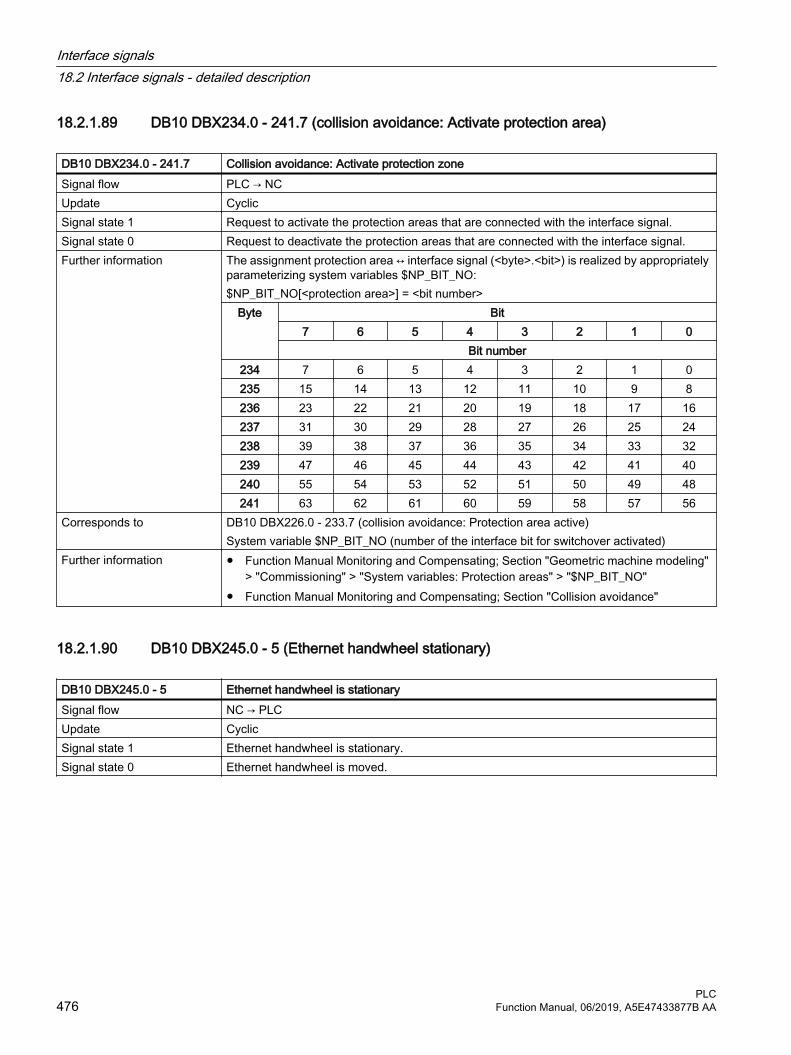
18.2.1.89 DB10 DBX234.0 - 241.7 (collision avoidance: Activate protection area)
DB10 DBX234.0 - 241.7 Collision avoidance: Activate protection zone Signal flow PLC → NCUpdate CyclicSignal state 1 Request to activate the protection areas that are connected with the interface signal.Signal state 0 Request to deactivate the protection areas that are connected with the interface signal.Further information The assignment protection area ↔ interface signal (<byte>.<bit>) is realized by appropriately
parameterizing system variables $NP_BIT_NO:$NP_BIT_NO[<protection area>] = <bit number>
Byte Bit7 6 5 4 3 2 1 0
Bit number234 7 6 5 4 3 2 1 0235 15 14 13 12 11 10 9 8236 23 22 21 20 19 18 17 16237 31 30 29 28 27 26 25 24238 39 38 37 36 35 34 33 32239 47 46 45 44 43 42 41 40240 55 54 53 52 51 50 49 48241 63 62 61 60 59 58 57 56
Corresponds to DB10 DBX226.0 - 233.7 (collision avoidance: Protection area active)System variable $NP_BIT_NO (number of the interface bit for switchover activated)
Further information ● Function Manual Monitoring and Compensating; Section "Geometric machine modeling" > "Commissioning" > "System variables: Protection areas" > "$NP_BIT_NO"
● Function Manual Monitoring and Compensating; Section "Collision avoidance"
18.2.1.90 DB10 DBX245.0 - 5 (Ethernet handwheel stationary)
DB10 DBX245.0 - 5 Ethernet handwheel is stationarySignal flow NC → PLCUpdate CyclicSignal state 1 Ethernet handwheel is stationary.Signal state 0 Ethernet handwheel is moved.
Interface signals18.2 Interface signals - detailed description
PLC476 Function Manual, 06/2019, A5E47433877B AA
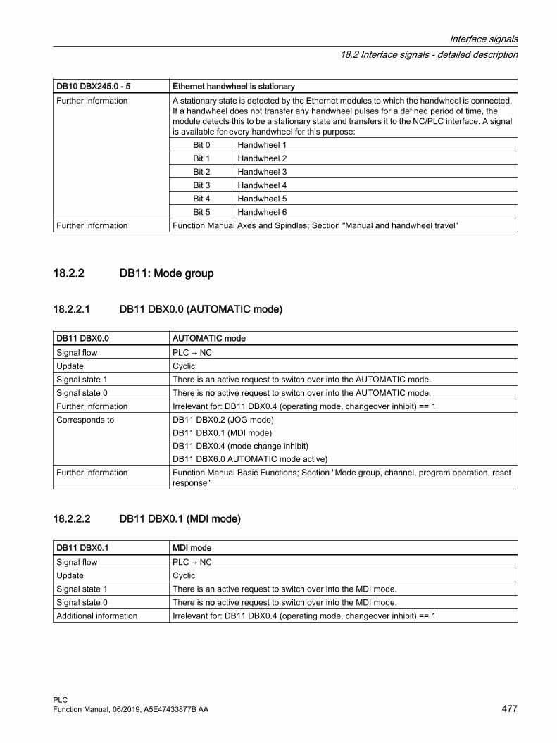
DB10 DBX245.0 - 5 Ethernet handwheel is stationaryFurther information A stationary state is detected by the Ethernet modules to which the handwheel is connected.
If a handwheel does not transfer any handwheel pulses for a defined period of time, the module detects this to be a stationary state and transfers it to the NC/PLC interface. A signal is available for every handwheel for this purpose:
Bit 0 Handwheel 1Bit 1 Handwheel 2Bit 2 Handwheel 3Bit 3 Handwheel 4Bit 4 Handwheel 5Bit 5 Handwheel 6
Further information Function Manual Axes and Spindles; Section "Manual and handwheel travel"
18.2.2 DB11: Mode group
18.2.2.1 DB11 DBX0.0 (AUTOMATIC mode)
DB11 DBX0.0 AUTOMATIC modeSignal flow PLC → NCUpdate CyclicSignal state 1 There is an active request to switch over into the AUTOMATIC mode.Signal state 0 There is no active request to switch over into the AUTOMATIC mode.Further information Irrelevant for: DB11 DBX0.4 (operating mode, changeover inhibit) == 1Corresponds to DB11 DBX0.2 (JOG mode)
DB11 DBX0.1 (MDI mode)DB11 DBX0.4 (mode change inhibit)DB11 DBX6.0 AUTOMATIC mode active)
Further information Function Manual Basic Functions; Section "Mode group, channel, program operation, reset response"
18.2.2.2 DB11 DBX0.1 (MDI mode)
DB11 DBX0.1 MDI modeSignal flow PLC → NCUpdate CyclicSignal state 1 There is an active request to switch over into the MDI mode.Signal state 0 There is no active request to switch over into the MDI mode.Additional information Irrelevant for: DB11 DBX0.4 (operating mode, changeover inhibit) == 1
Interface signals18.2 Interface signals - detailed description
PLCFunction Manual, 06/2019, A5E47433877B AA 477

DB11 DBX0.1 MDI modeCorresponds with DB11 DBX0.0 (AUTOMATIC mode)
DB11 DBX0.2 (JOG mode)DB11 DBX0.4 (mode change inhibit)DB11 DBX6.1 (active MDI mode)
Additional references Basic Functions Function Manual; Chapter "K1: mode group, channel, program mode, reset response"
18.2.2.3 DB11 DBX0.2 (JOG mode)
DB11 DBX0.2 JOG modeSignal flow PLC → NCUpdate CyclicSignal state 1 There is an active request to switch over into the JOG mode.Signal state 0 There is no active request to switch over into the JOG mode.Further information Irrelevant for: DB11 DBX0.4 (operating mode, changeover inhibit) == 1Corresponds to DB11 DBX0.0 (AUTOMATIC mode)
DB11 DBX0.1 (MDI mode)DB11 DBX0.4 (mode change inhibit)DB11 DBX6.2 (JOG mode active)
Further information Function Manual Basic Functions; Section "Mode group, channel, program operation, reset response"
18.2.2.4 DB11 DBX0.4 (mode change inhibit)
DB11 DBX0.4 Mode change inhibitSignal flow PLC → NCUpdate CyclicSignal state 1 The active mode of the mode group cannot be changed.
NoteThe machine functions that can be selected within a mode group can be changed.
Signal state 0 The mode of the mode group can be changed.Corresponds to DB11 DBX0.0 (AUTOMATIC mode)
DB11 DBX0.1 (MDI mode)DB11 DBX0.2 (JOG mode)
Further information Function Manual Basic Functions; Section "Mode group, channel, program operation, reset response"
Interface signals18.2 Interface signals - detailed description
PLC478 Function Manual, 06/2019, A5E47433877B AA

18.2.2.5 DB11 DBX0.5 (mode group stop)
DB11 DBX0.5 Mode group stopSignal flow PLC → NCUpdate CyclicSignal state 1 There is an active request for "Mode group stop".
Responses:● An "NC Stop" is initiated for all the channels of the mode group. ● Channel state change as a result of the mode group stop:
– "Active" → "Interrupted"– "Reset" → "Reset"
● Program state change as a result of the mode group stop– "Running" → "Stopped"
● All traversing axes of the mode group are braked without contour violation to zero speed along their acceleration curves
Programs that have been stopped can be restarted with "NC Start". The spindles of the mode group are not influenced.
Signal state 0 There is no active request for "Mode group stop".Corresponds to DB21, ... .DBX7.2 (NC start)
DB21, ... .DBX7.3 (NC stop)Further information Function Manual Basic Functions; Section "Mode group, channel, program operation, reset
response"
18.2.2.6 DB11 DBX0.6 (mode group stop, axes plus spindles)
DB11 DBX0.6 Mode group stop axes plus spindlesSignal flow PLC → NCUpdate CyclicSignal state 1 There is an active request for "Mode group stop axes plus spindles".
Responses:● An "NC Stop" is initiated for all the channels of the mode group. ● Channel state change as a result of the mode group stop:
– "Active" → "Interrupted"– "Reset" → "Reset"
● Program state change as a result of the mode group stop– "Running" → "Stopped"
● All traversing axes and spindles of the mode group are braked without contour violation to zero speed along their acceleration curves
Programs that have been stopped can be restarted with "NC Start". Signal state 0 There is no active request for "Mode group stop axes plus spindles".
Interface signals18.2 Interface signals - detailed description
PLCFunction Manual, 06/2019, A5E47433877B AA 479

DB11 DBX0.6 Mode group stop axes plus spindlesCorresponds to DB21, ... .DBX7.2 (NC start)
DB21, ... .DBX7.3 (NC stop)Further information Function Manual Basic Functions; Section "Mode group, channel, program operation, reset
response"
18.2.2.7 DB11 DBX0.7 (mode group reset)
DB11 DBX0.7 Mode group resetSignal flow PLC → NCUpdate CyclicEdge change 0 → 1 A request was initiated for a "Mode group reset".
Responses:● In all channels of the mode group, a "channel reset" is initiated in the control system
corresponding to DB21, ... DBX 7.7 = 1.● All the channels are then in the channel state "reset" (DB21, ... DBX35.7 == 1)● All active NC programs are then in the "canceled" program state (DB21, ... DBX35.4 == 1)● All traversing axes and spindles are decelerated without contour violation to zero speed
according to their acceleration curves. ● The channel-specific reset positions become active.● All alarms of the mode group are cleared - with the exception of power on alarms.
Edge change 1 → 0 Reset of the last request for a "Mode group reset".Starting at this time, a new "Mode group reset" can be requested.
Further information Special caseIf an alarm resets the interface signal DB11 DBX6.3 (mode group ready), all channels of the mode group are no longer in the "reset" channel state. In order that the mode of the mode group can be switched over, initially, a "Mode group reset" must be initiated using DB11 DBX0.7. NoteBefore a new action can be requested in a channel of the mode group from the PLC user program after a mode group reset (e.g. NC start or axis interchange), the system must first wait for either the mode group state "All channels of the mode group in the reset state" (DB11 DBX6.7 == 1) - or the channel state "Reset" (DB21, ... DBX35.7 == 1) of the channel involved.
Corresponds to DB21, ... DBX7.7 (channel reset)DB11 DBX6.7 (all channels in the reset state)
Further information Function Manual Basic Functions; Section "Mode group, channel, program operation, reset response"
18.2.2.8 DB11 DBX1.0 (TEACH IN machine function)
DB11 DBX1.0 TEACH IN machine functionSignal flow PLC → NCUpdate CyclicSignal state 1 There is an active request to activate the TEACH IN machine function.
Interface signals18.2 Interface signals - detailed description
PLC480 Function Manual, 06/2019, A5E47433877B AA

DB11 DBX1.0 TEACH IN machine functionSignal state 0 There is no active request to activate the TEACH IN machine function.Further information Note
Only active in the JOG mode.Corresponds to DB11 DBX6.2 (JOG mode active)
DB11 DBX7.1 (TEACH IN machine function active)Further information Function Manual Basic Functions; Section "Mode group, channel, program operation, reset
response"
18.2.2.9 DB11 DBX1.1 (REPOS machine function)
DB11 DBX1.1 REPOS machine functionSignal flow PLC → NCUpdate CyclicSignal state 1 There is an active request to activate the REPOS machine function.Signal state 0 There is no active request to activate the REPOS machine function.Further information Note
Only active in the JOG mode.Corresponds to DB11 DBX6.2 (JOG mode active)
DB11 DBX7.2 (REPOS machine function active)Further information Function Manual Basic Functions; Section "Mode group, channel, program operation, reset
response"
18.2.2.10 DB11 DBX1.2 (REF machine function)
DB11 DBX1.2 REF machine functionSignal flow PLC → NCUpdate CyclicSignal state 1 There is an active request to activate the REF machine function.Signal state 0 There is no active request to activate the REF machine function.Further information Note
Only active in the JOG mode.Corresponds to DB11 DBX6.2 (JOG mode active)
DB11 DBX7.3 (REF machine function active)Further information Function Manual Basic Functions; Section "Mode group, channel, program operation, reset
response" and "R1: referencing"
18.2.2.11 DB11 DBX1.6 (single block, type B)
DB11 DBX1.6 Single block, type BSignal flow PLC → NCUpdate Cyclic
Interface signals18.2 Interface signals - detailed description
PLCFunction Manual, 06/2019, A5E47433877B AA 481
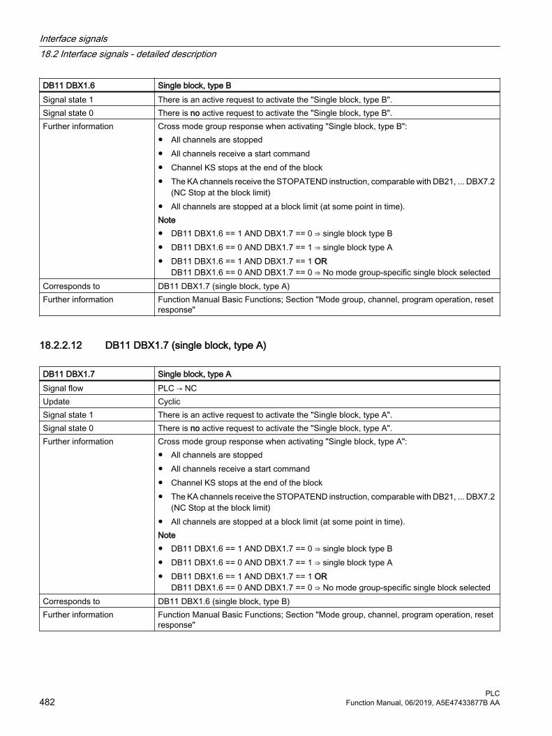
DB11 DBX1.6 Single block, type BSignal state 1 There is an active request to activate the "Single block, type B".Signal state 0 There is no active request to activate the "Single block, type B".Further information Cross mode group response when activating "Single block, type B":
● All channels are stopped● All channels receive a start command● Channel KS stops at the end of the block● The KA channels receive the STOPATEND instruction, comparable with DB21, ... DBX7.2
(NC Stop at the block limit)● All channels are stopped at a block limit (at some point in time).Note● DB11 DBX1.6 == 1 AND DBX1.7 == 0 ⇒ single block type B● DB11 DBX1.6 == 0 AND DBX1.7 == 1 ⇒ single block type A● DB11 DBX1.6 == 1 AND DBX1.7 == 1 OR
DB11 DBX1.6 == 0 AND DBX1.7 == 0 ⇒ No mode group-specific single block selectedCorresponds to DB11 DBX1.7 (single block, type A)Further information Function Manual Basic Functions; Section "Mode group, channel, program operation, reset
response"
18.2.2.12 DB11 DBX1.7 (single block, type A)
DB11 DBX1.7 Single block, type ASignal flow PLC → NCUpdate CyclicSignal state 1 There is an active request to activate the "Single block, type A".Signal state 0 There is no active request to activate the "Single block, type A".Further information Cross mode group response when activating "Single block, type A":
● All channels are stopped● All channels receive a start command● Channel KS stops at the end of the block● The KA channels receive the STOPATEND instruction, comparable with DB21, ... DBX7.2
(NC Stop at the block limit)● All channels are stopped at a block limit (at some point in time).Note● DB11 DBX1.6 == 1 AND DBX1.7 == 0 ⇒ single block type B● DB11 DBX1.6 == 0 AND DBX1.7 == 1 ⇒ single block type A● DB11 DBX1.6 == 1 AND DBX1.7 == 1 OR
DB11 DBX1.6 == 0 AND DBX1.7 == 0 ⇒ No mode group-specific single block selectedCorresponds to DB11 DBX1.6 (single block, type B)Further information Function Manual Basic Functions; Section "Mode group, channel, program operation, reset
response"
Interface signals18.2 Interface signals - detailed description
PLC482 Function Manual, 06/2019, A5E47433877B AA

18.2.2.13 DB11 DBX4.0 (AUTOMATIC mode selected)
DB11 DBX4.0 AUTOMATIC mode selectedSignal flow HMI → PLCUpdate CyclicSignal state 1 There is an active HMI request to select the AUTOMATIC mode. Signal state 0 There is no active HMI request to select the AUTOMATIC mode. Corresponds to DB11 DBX0.0 (AUTOMATIC mode)Further information Function Manual Basic Functions; Section "Mode group, channel, program operation, reset
response"
18.2.2.14 DB11 DBX4.1 (MDI mode selected)
DB11 DBX4.1 MDI mode selectedSignal flow HMI → PLCUpdate CyclicSignal state 1 There is an active HMI request to select the MDI mode. Signal state 0 There is no active HMI request to select the MDI mode. Corresponds to DB11 DBX0.1 (MDI mode)Further information Function Manual Basic Functions; Section "Mode group, channel, program operation, reset
response"
18.2.2.15 DB11 DBX4.2 (JOG mode selected)
DB11 DBX4.2 JOG mode selectedSignal flow HMI → PLCUpdate CyclicSignal state 1 There is an active HMI request to select the JOG mode. Signal state 0 There is no active HMI request to select the JOG mode. Corresponds to DB11 DBX0.2 (JOG mode)Further information Function Manual Basic Functions; Section "Mode group, channel, program operation, reset
response"
18.2.2.16 DB11 DBX5.0 (TEACH IN machine function selected)
DB11 DBX5.0 TEACH IN machine function selectedSignal flow HMI → PLCUpdate CyclicSignal state 1 There is an active HMI request to select the TEACH IN machine function. Signal state 0 There is no active HMI request to select the TEACH IN machine function.
Interface signals18.2 Interface signals - detailed description
PLCFunction Manual, 06/2019, A5E47433877B AA 483

DB11 DBX5.0 TEACH IN machine function selectedCorresponds to DB11 DBX7.1 (active TEACH IN machine function)Further information Function Manual Basic Functions; Section "Mode group, channel, program operation, reset
response"
18.2.2.17 DB11 DBX5.1 (REPOS machine function selected)
DB11 DBX5.1 REPOS machine function selectedSignal flow HMI → PLCUpdate CyclicSignal state 1 There is an active HMI request to select the REPOS machine function. Signal state 0 There is no active HMI request to select the REPOS machine function. Corresponds to DB11 DBX7.2 (active REPOS machine function)Further information Function Manual Basic Functions; Section "Mode group, channel, program operation, reset
response"
18.2.2.18 DB11 DBX5.2 (REF machine function selected)
DB11 DBX5.2 REF machine function selectedSignal flow HMI → PLCUpdate CyclicSignal state 1 There is an active HMI request to select the REF machine function. Signal state 0 There is no active HMI request to select the REF machine function. Corresponds to DB11 DBX7.3 (active REF machine function)Further information Function Manual Basic Functions; Section "Mode group, channel, program operation, reset
response"
18.2.2.19 DB11 DBX6.0 (AUTOMATIC mode active)
DB11 DBX6.0 AUTOMATIC mode activeSignal flow NC → PLCUpdate CyclicSignal state 1 The AUTOMATIC mode is active.Signal state 0 The AUTOMATIC mode is not active.Corresponds to DB11 DBX0.0 (AUTOMATIC mode)Further information Function Manual Basic Functions; Section "Mode group, channel, program operation, reset
response"
Interface signals18.2 Interface signals - detailed description
PLC484 Function Manual, 06/2019, A5E47433877B AA

18.2.2.20 DB11 DBX6.1 (active MDI mode)
DB11 DBX6.1 Active MDI mode Signal flow NC → PLCUpdate CyclicSignal state 1 The MDI mode is active.Signal state 0 The MDI mode is not active.Corresponds to DB11 DBX0.1 (MDI mode)Further information Function Manual Basic Functions; Section "Mode group, channel, program operation, reset
response"
18.2.2.21 DB11 DBX6.2 (JOG mode active)
DB11 DBX6.2 Active JOG modeSignal flow NC → PLCUpdate CyclicSignal state 1 The JOG mode is active.Signal state 0 The JOG mode is not active.Corresponds to DB11 DBX0.2 (JOG mode)Further information Function Manual Basic Functions; Section "Mode group, channel, program operation, reset
response"
18.2.2.22 DB11 DBX6.3 (mode group ready)
DB11 DBX6.3 Mode group readySignal flow NC → PLCUpdate CyclicSignal state 1 The mode group is ready.Signal state 0 The mode group is ready. Further information Response when the signal changes from 0 → 1:
● Traversing axes and spindles are braked down to standstill with setpoint 0 or maximum braking current.
● The interface signals from the PLC to the NC are brought into an inactive state (reset position).
NoteIf an alarm occurs that clears "Mode group ready", before switching over the mode, a mode group reset (DB11 DBX 0.7) must first be initiated.
Corresponds to DB11 DBX0.7 (mode group reset)Further information Function Manual Basic Functions; Section "Mode group, channel, program operation, reset
response"
Interface signals18.2 Interface signals - detailed description
PLCFunction Manual, 06/2019, A5E47433877B AA 485

18.2.2.23 DB11 DBX6.7 (all channels in the "Reset" state)
DB11 DBX6.7 All channels in the "Reset" stateSignal flow NC → PLCUpdate CyclicSignal state 1 All mode group channels are in the "Reset" state.Signal state 0 At least one channel of the mode group is not in the "Reset" state.Corresponds to DB21, ... DBX7.7 (channel state, "Reset")Further information Function Manual Basic Functions; Section "Mode group, channel, program operation, reset
response"
18.2.2.24 DB11 DBX7.0 (TEACH IN machine function active)
DB11 DBX7.0 TEACH IN machine function activeSignal flow NC → PLCUpdate CyclicSignal state 1 The TEACH IN machine function is active.Signal state 0 The TEACH IN machine function is not active.Corresponds to DB11 DBX1.0 (TEACH IN machine function)
DB11 DBX5.0 (TEACH IN machine function selected)Further information Function Manual Basic Functions; Section "Mode group, channel, program operation, reset
response"
18.2.2.25 DB11 DBX7.1 (REPOS machine function active)
DB11 DBX7.1 REPOS machine function activeSignal flow NC → PLCUpdate CyclicSignal state 1 Machine function REPOS is active.Signal state 0 Machine function REPOS is not active.Corresponds to DB11 DBX1.1 (REPOS machine function)
DB11 DBX5.1 (REPOS machine function selected)Further information Function Manual Basic Functions; Section "Mode group, channel, program operation, reset
response"
18.2.2.26 DB11 DBX7.2 (REF machine function active)
DB11 DBX7.2 REF machine function activeSignal flow NC → PLCUpdate CyclicSignal state 1 Machine function REF is active.
Interface signals18.2 Interface signals - detailed description
PLC486 Function Manual, 06/2019, A5E47433877B AA
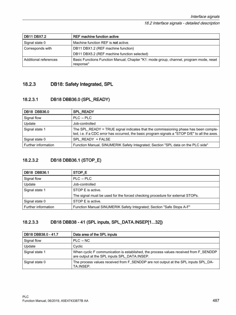
DB11 DBX7.2 REF machine function activeSignal state 0 Machine function REF is not active.Corresponds with DB11 DBX1.2 (REF machine function)
DB11 DBX5.2 (REF machine function selected)Additional references Basic Functions Function Manual; Chapter "K1: mode group, channel, program mode, reset
response"
18.2.3 DB18: Safety Integrated, SPL
18.2.3.1 DB18 DBB36.0 (SPL_READY)
DB18 DBB36.0 SPL_READYSignal flow PLC → PLCUpdate Job-controlledSignal state 1 The SPL_READY = TRUE signal indicates that the commissioning phase has been comple‐
ted, i.e. if a CDC error has occurred, the basic program signals a "STOP D/E" to all the axes.Signal state 0 SPL_READY = FALSEFurther information Function Manual, SINUMERIK Safety Integrated; Section "SPL data on the PLC side"
18.2.3.2 DB18 DBB36.1 (STOP_E)
DB18 DBB36.1 STOP_ESignal flow PLC → PLCUpdate Job-controlledSignal state 1 STOP E is active.
The signal must be used for the forced checking procedure for external STOPs.Signal state 0 STOP E is active.Further information Function Manual SINUMERIK Safety Integrated; Section "Safe Stops A-F"
18.2.3.3 DB18 DBB38 - 41 (SPL inputs, SPL_DATA.INSEP[1...32])
DB18 DBB38.0 - 41.7 Data area of the SPL inputsSignal flow PLC → NCUpdate CyclicSignal state 1 When cyclic F communication is established, the process values received from F_SENDDP
are output at the SPL inputs SPL_DATA.INSEP.Signal state 0 The process values received from F_SENDDP are not output at the SPL inputs SPL_DA‐
TA.INSEP.
Interface signals18.2 Interface signals - detailed description
PLCFunction Manual, 06/2019, A5E47433877B AA 487

DB18 DBB38.0 - 41.7 Data area of the SPL inputsFurther information Byte Bit
7 6 5 4 3 2 1 0Bit number
38 7 6 5 4 3 2 1 039 15 14 13 12 11 10 9 840 23 22 21 20 19 18 17 1641 31 30 29 28 27 26 25 24
Corresponds to $A_INSEFurther information Function Manual Safety Integrated; Section "Safety-oriented CPU-CPU communication"
18.2.3.4 DB18 DBB42.0 - 45.7 (SPL inputs, SPL_DATA.INSEP[33...64])
DB18 DBB42.0 - 45.7 Data area of the SPL inputsSignal flow PLC → NCUpdate CyclicSignal state 1 When cyclic F communication is established, the process values received from F_SENDDP
are output at the SPL inputs SPL_DATA.INSEP.Signal state 0 The process values received from F_SENDDP are not output at the SPL inputs SPL_DA‐
TA.INSEP.Further information Byte Bit
7 6 5 4 3 2 1 0Bit number
42 39 38 37 36 35 34 33 3243 47 46 45 44 43 42 41 4044 55 54 53 52 51 50 49 4845 63 62 61 60 59 58 57 56
Corresponds to $A_INSEFurther information Function Manual Safety Integrated; Section "Safety-oriented CPU-CPU communication"
18.2.3.5 DB18 DBB46.0 - 49.7 (SPL outputs, SPL_DATA.OUTSEP[1...32]
DB18 DBB46.0 - 49.7 Data area of the SPL outputsSignal flow PLC → NCUpdate CyclicSignal state 1 The received process values are output at the SPL outputs SPL_DATA.OUTSEP.Signal state 0 The received process values are not output at the SPL outputs SPL_DATA.OUTSEP.
Interface signals18.2 Interface signals - detailed description
PLC488 Function Manual, 06/2019, A5E47433877B AA
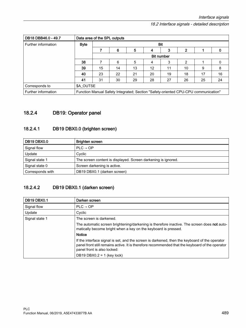
DB18 DBB46.0 - 49.7 Data area of the SPL outputsFurther information Byte Bit
7 6 5 4 3 2 1 0Bit number
38 7 6 5 4 3 2 1 039 15 14 13 12 11 10 9 840 23 22 21 20 19 18 17 1641 31 30 29 28 27 26 25 24
Corresponds to $A_OUTSEFurther information Function Manual Safety Integrated; Section "Safety-oriented CPU-CPU communication"
18.2.4 DB19: Operator panel
18.2.4.1 DB19 DBX0.0 (brighten screen)
DB19 DBX0.0 Brighten screenSignal flow PLC → OPUpdate CyclicSignal state 1 The screen content is displayed. Screen darkening is ignored.Signal state 0 Screen darkening is active.Corresponds with DB19 DBX0.1 (darken screen)
18.2.4.2 DB19 DBX0.1 (darken screen)
DB19 DBX0.1 Darken screenSignal flow PLC → OPUpdate CyclicSignal state 1 The screen is darkened.
The automatic screen brightening/darkening is therefore inactive. The screen does not auto‐matically become bright when a key on the keyboard is pressed.NoticeIf the interface signal is set, and the screen is darkened, then the keyboard of the operator panel front still remains active. It is therefore recommended that the keyboard of the operator panel front is also locked:DB19 DBX0.2 = 1 (key lock)
Interface signals18.2 Interface signals - detailed description
PLCFunction Manual, 06/2019, A5E47433877B AA 489

DB19 DBX0.1 Darken screenSignal state 0 The screen is brightened.
In this state, the control automatically brightens/darkens the screen:● The screen is darkened if no keystroke is made at the keyboard for a time that is defined
using the following machine data:MD9006 $MM_DISPLAY_SWITCH_OFF_INTERVAL (time to darken the screen) The default setting is 15 minutes.
● The screen is brightened the next time a key on the operator panel front is pressed.Corresponds with DB19 DBX0.0 (brighten screen)
DB19 DBX0.2 (key lock)MD9006 $MM_DISPLAY_SWITCH_OFF_INTERVAL (time to darken the screen)
18.2.4.3 DB19 DBX0.2 (key lock)
DB19 DBX0.2 Key lockSignal flow PLC → OPUpdate CyclicSignal state 1 The keyboard is locked for the user.Signal state 0 The keyboard is enabled for the user.Additional information If the screen is darkened with the interface signal: DB19 DBX0.1 (darken screen), the key‐
board should be locked simultaneously with the interface signal: DB19 DBX0.2 (key lock) to avoid an unintended operation. NoticeIf the screen is darkened with (DB19 DBX0.1 = 1), the operator panel front keyboard still remains functional. It is therefore recommended that the keyboard of the operator panel front is also locked:DB19 DBX0.2 = 1 (key lock)
Corresponds with DB19 DBX0.0 (brighten screen)DB19 DBX0.1 (darken screen)
18.2.4.4 DB19 DBX0.3 (delete cancel alarms)
DB19 DBX0.3 Delete cancel alarmsSignal flow PLC → OPUpdate CyclicSignal state 1 The delete error key on the operator panel is pressed ⇒
Request to acknowledge all cancel alarms of the NC and operator panel.Signal state 0 The delete error key is not pressed on the operator panel.Corresponds with DB19 DBX20.3 (cancel alarms deleted)
Interface signals18.2 Interface signals - detailed description
PLC490 Function Manual, 06/2019, A5E47433877B AA

18.2.4.5 DB19 DBX0.4 (delete recall alarms)
DB19 DBX0.4 Delete recall alarmsSignal flow PLC → OPUpdate CyclicSignal state 1 The delete error key is pressed on the operator panel.
Request to acknowledge all recall alarms of the NC and operator panel.Signal state 0 The delete error key is not pressed on the operator panel.Corresponds with DB19 DBX20.4 (recall alarms deleted)
18.2.4.6 DB19 DBX0.7 (actual values in the WCS)
DB19 DBX0.7 Actual values in the WCSSignal flow PLC → OPUpdate CyclicSignal state 1 If the "machine" operating area is selected on the user interface, the axis-specific positions
and distance-to-go are displayed in the workpiece coordinate system (WCS).Signal state 0 If the "machine" operating area is selected on the user interface, the axis-specific positions
and distance-to-go are displayed in the previous active coordinate system.Additional information Within the "machine" operating area, the coordinate system can be displayed in which the
axis-specific positions and distances-to-go are switched via the "MCS actual values" and "WCS actual values" softkeys:
Corresponds with DB19 DBX20.7 (switch MCS/WCS)
18.2.4.7 DB19 DBB6 (analog spindle 1, utilization as a percentage)
DB19 DBB6 Analog spindle 1, utilization in percentSignal flow PLC → OPUpdate CyclicAdditional information Format: UINT (unsigned, 0 ... 255D or 0 ... FFH)
18.2.4.8 DB19 DBB7 (analog spindle 2, utilization as a percentage)
DB19 DBB7 Analog spindle 2, utilization in percentSignal flow PLC → OPUpdate CyclicAdditional information Format: UINT (unsigned, 0 ... 255D or 0 ... FFH)
Interface signals18.2 Interface signals - detailed description
PLCFunction Manual, 06/2019, A5E47433877B AA 491

18.2.4.9 DB19 DBB8 (channel number)
DB19 DBB8 Channel numberSignal flow PLC → OPUpdate CyclicAdditional information Format: UINT (unsigned, 0 ... 255D or 0 ... FFH)
Valid channel numbers: 1 ... maximum number of NC channels
18.2.4.10 DB19 DBB10 (PLC hardkeys)
DB19 DBB10 PLC hardkeysSignal flow PLC → OPUpdate CyclicSignal state ≠ 0 1 ... 255: Selects the corresponding programming areaSignal state == 0 0: No selectionAdditional information Format: UINT (unsigned, 0 ... 255D or 0 ... FFH)
18.2.4.11 DB19 DBX13.5 (NC program: unload)
DB19 DBX13.5 NC program: UnloadSignal flow PLC → OPUpdate CyclicSignal state 1 Unload activeSignal state 0 Unload not active
18.2.4.12 DB19DBX13.6 (NC program: load)
DB19 DBX13.6 NC program: LoadSignal flow PLC → OPUpdate CyclicSignal state 1 Load activeSignal state 0 Load not active
18.2.4.13 DB19 DBX13.7 (NC program: selection)
DB19 DBX13.7 NC program: SelectionSignal flow PLC → OPUpdate CyclicSignal state 1 Selection activeSignal state 0 Selection not active
Interface signals18.2 Interface signals - detailed description
PLC492 Function Manual, 06/2019, A5E47433877B AA

18.2.4.14 DB19 DBX14.0 - 6 (PLC index)
DB19 DBX14.0 - 6 PLC indexSignal flow PLC → OPUpdate CyclicAdditional information The V24 interface is controlled with bits 0 - 6. They specify the PLC index for the standard
control file, which specifies the axis, channel or TO number.The file system is selected via:● DB19 DBX14.7 == 1 ⇒ passive file system: PLC index for the user control file● DB19 DBX14.7 == 0 ⇒ active file system: PLC index, which specifies the axis, channel or
TO number.Format: UINT (unsigned, 0 ... 127D or 0 ... 7FH)
Corresponds with DB19 DBX14.7 (selects the file system)
18.2.4.15 DB19 DBX14.7 (selects the file system)
DB19 DBX14.7 Selects the file systemSignal flow PLC → OPUpdate CyclicSignal state 1 Passive file systemSignal state 0 Active file systemCorresponds with DB19 DBX14.0 - 6 (PLC index)
18.2.4.16 DB19 DBB15 (PLC line offset)
DB19 DBB15 PLC line offsetSignal flow PLC → OPUpdate CyclicAdditional information The byte to control the V24 interface defines the line of the standard or user control file in
which the control file to be transferred is specified.The control file is selected using:● DB19 DBX14.7 == 1 ⇒ passive file system: PLC line offset in a user control file● DB19 DBX14.7 == 0 ⇒ active file system: PLC line offset in a standard control fileFormat: UINT (unsigned, 0 ... 255D or 0 ... FFH)
Corresponds with DB19 DBX14.7 (selects the file system)
18.2.4.17 DB19 DBB16 (program selection from the PLC: Index of the program list)
DB19 DBB16 Program selection from the PLC: Index of the program listSignal flow PLC → OPUpdate Cyclic
Interface signals18.2 Interface signals - detailed description
PLCFunction Manual, 06/2019, A5E47433877B AA 493
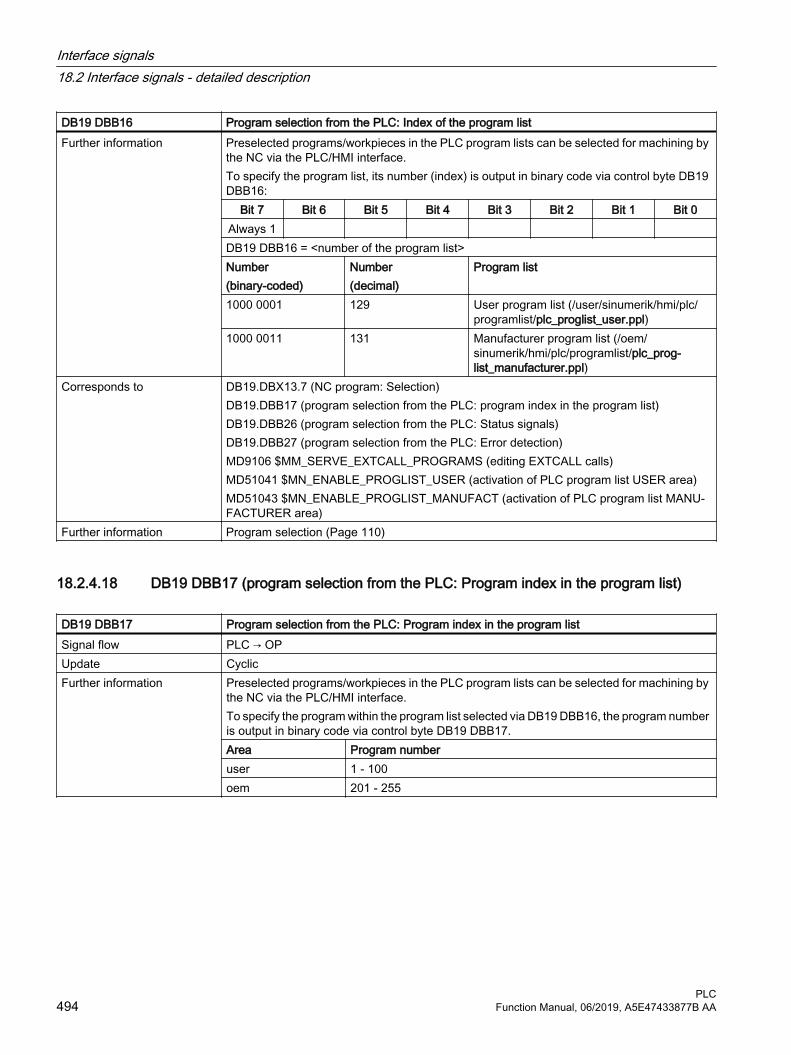
DB19 DBB16 Program selection from the PLC: Index of the program listFurther information Preselected programs/workpieces in the PLC program lists can be selected for machining by
the NC via the PLC/HMI interface.To specify the program list, its number (index) is output in binary code via control byte DB19 DBB16:
Bit 7 Bit 6 Bit 5 Bit 4 Bit 3 Bit 2 Bit 1 Bit 0Always 1 DB19 DBB16 = <number of the program list>Number(binary-coded)
Number(decimal)
Program list
1000 0001 129 User program list (/user/sinumerik/hmi/plc/programlist/plc_proglist_user.ppl)
1000 0011 131 Manufacturer program list (/oem/sinumerik/hmi/plc/programlist/plc_prog‐list_manufacturer.ppl)
Corresponds to DB19.DBX13.7 (NC program: Selection)DB19.DBB17 (program selection from the PLC: program index in the program list)DB19.DBB26 (program selection from the PLC: Status signals)DB19.DBB27 (program selection from the PLC: Error detection)MD9106 $MM_SERVE_EXTCALL_PROGRAMS (editing EXTCALL calls)MD51041 $MN_ENABLE_PROGLIST_USER (activation of PLC program list USER area)MD51043 $MN_ENABLE_PROGLIST_MANUFACT (activation of PLC program list MANU‐FACTURER area)
Further information Program selection (Page 110)
18.2.4.18 DB19 DBB17 (program selection from the PLC: Program index in the program list)
DB19 DBB17 Program selection from the PLC: Program index in the program listSignal flow PLC → OPUpdate CyclicFurther information Preselected programs/workpieces in the PLC program lists can be selected for machining by
the NC via the PLC/HMI interface.To specify the program within the program list selected via DB19 DBB16, the program number is output in binary code via control byte DB19 DBB17.Area Program numberuser 1 - 100oem 201 - 255
Interface signals18.2 Interface signals - detailed description
PLC494 Function Manual, 06/2019, A5E47433877B AA

DB19 DBB17 Program selection from the PLC: Program index in the program listCorresponds to DB19.DBX13.7 (NC program: Selection)
DB19.DBB16 (program selection from the PLC: index of the program list)DB19.DBB26 (program selection from the PLC: Status signals)DB19.DBB27 (program selection from the PLC: Error detection)MD9106 $MM_SERVE_EXTCALL_PROGRAMS (editing EXTCALL calls)MD51041 $MN_ENABLE_PROGLIST_USER (activation of PLC program list USER area)MD51043 $MN_ENABLE_PROGLIST_MANUFACT (activation of PLC program list MANU‐FACTURER area)
Further information Program selection (Page 110)
18.2.4.19 DB19 DBX20.1 (screen is dark)
DB19 DBX20.1 Screen is darkSignal flow OP → PLCUpdate CyclicSignal state 1 The screen is darkened.Signal state 0 The screen is not darkened.Corresponds with DB19 DBX0.1 (darken screen)
MD9006 $MM_DISPLAY_SWITCH_OFF_INTERVAL (time for the screen darkening)
18.2.4.20 DB19 DBX20.3 (cancel alarms deleted)
DB19 DBX20.3 Cancel alarm deletedSignal flow OP → PLCUpdate CyclicSignal state 1 Feedback: Cancel alarms were deleted.Signal state 0 Note
The interface signal must be reset in the PLC user program.Corresponds with DB19 DBX0.3 (delete cancel alarms)
18.2.4.21 DB19 DBX20.4 (recall alarms deleted)
DB19 DBX20.4 Recall alarms deletedSignal flow OP → PLCUpdate CyclicSignal state 1 Feedback: Recall alarms were deletedSignal state 0 Note
The interface signal must be reset in the PLC user program.Corresponds with DB19 DBX0.4 (delete recall alarms)
Interface signals18.2 Interface signals - detailed description
PLCFunction Manual, 06/2019, A5E47433877B AA 495
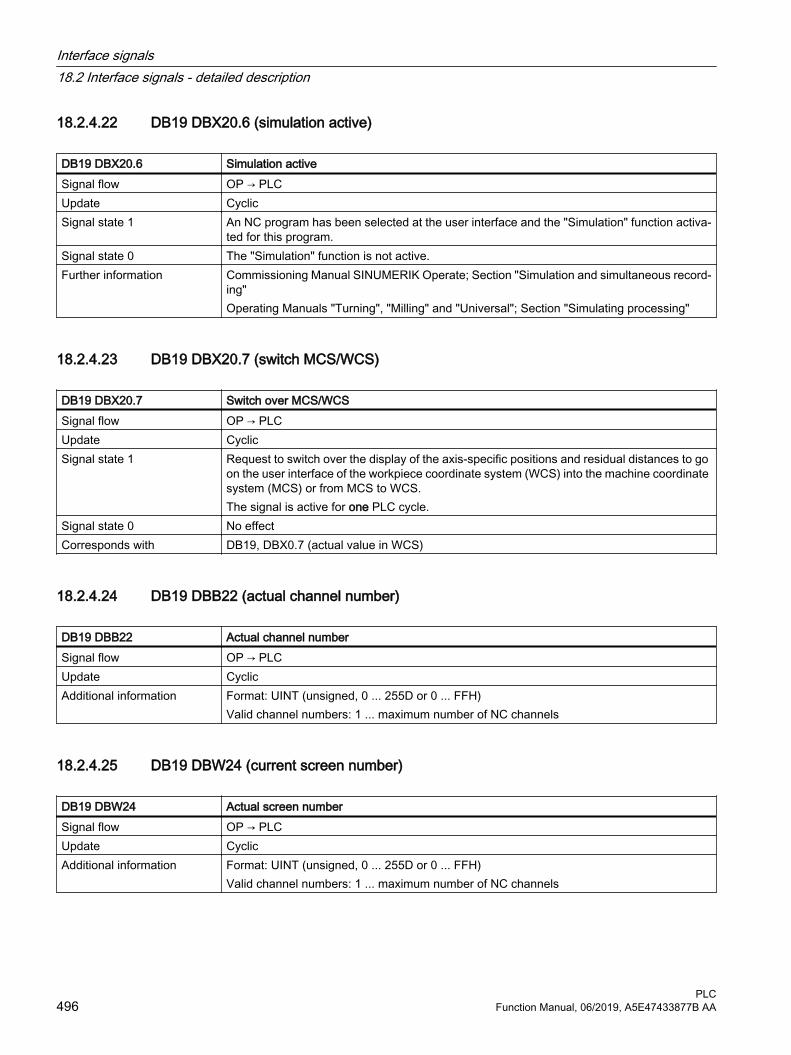
18.2.4.22 DB19 DBX20.6 (simulation active)
DB19 DBX20.6 Simulation activeSignal flow OP → PLCUpdate CyclicSignal state 1 An NC program has been selected at the user interface and the "Simulation" function activa‐
ted for this program.Signal state 0 The "Simulation" function is not active.Further information Commissioning Manual SINUMERIK Operate; Section "Simulation and simultaneous record‐
ing"Operating Manuals "Turning", "Milling" and "Universal"; Section "Simulating processing"
18.2.4.23 DB19 DBX20.7 (switch MCS/WCS)
DB19 DBX20.7 Switch over MCS/WCSSignal flow OP → PLCUpdate CyclicSignal state 1 Request to switch over the display of the axis-specific positions and residual distances to go
on the user interface of the workpiece coordinate system (WCS) into the machine coordinate system (MCS) or from MCS to WCS. The signal is active for one PLC cycle.
Signal state 0 No effectCorresponds with DB19, DBX0.7 (actual value in WCS)
18.2.4.24 DB19 DBB22 (actual channel number)
DB19 DBB22 Actual channel numberSignal flow OP → PLCUpdate CyclicAdditional information Format: UINT (unsigned, 0 ... 255D or 0 ... FFH)
Valid channel numbers: 1 ... maximum number of NC channels
18.2.4.25 DB19 DBW24 (current screen number)
DB19 DBW24 Actual screen numberSignal flow OP → PLCUpdate CyclicAdditional information Format: UINT (unsigned, 0 ... 255D or 0 ... FFH)
Valid channel numbers: 1 ... maximum number of NC channels
Interface signals18.2 Interface signals - detailed description
PLC496 Function Manual, 06/2019, A5E47433877B AA

18.2.4.26 DB19 DBX26.1 (program selection from the PLC: Job completed)
DB19 DBX26.1 Program selection from the PLC: Job completedSignal flow OP → PLCUpdate CyclicSignal state 1 Program selection from the PLC: Job completedSignal state 0 Program selection from the PLC: Job not completedCorresponds to DB19.DBX13.7 (NC program: Selection)
DB19.DBB16 (program selection from the PLC: index of the program list)DB19.DBB17 (program selection from the PLC: program index in the program list)DB19.DBB26 (program selection from the PLC: Status signals)DB19.DBB27 (program selection from the PLC: Error detection)MD9106 $MM_SERVE_EXTCALL_PROGRAMS (editing EXTCALL calls)MD51041 $MN_ENABLE_PROGLIST_USER (activation of PLC program list USER area)MD51043 $MN_ENABLE_PROGLIST_MANUFACT (activation of PLC program list MANU‐FACTURER area)
Further information Program selection (Page 110)
18.2.4.27 DB19 DBX26.2 (program selection from the PLC: Error)
DB19 DBX26.2 Program selection from the PLC: ErrorSignal flow OP → PLCUpdate CyclicSignal state 1 Program selection from the PLC: Job completed with errorsSignal state 0 Program selection from the PLC: Job completed correctlyCorresponds to DB19.DBX13.7 (NC program: Selection)
DB19.DBB16 (program selection from the PLC: index of the program list)DB19.DBB17 (program selection from the PLC: program index in the program list)DB19.DBB26 (program selection from the PLC: Status signals)DB19.DBB27 (program selection from the PLC: Error detection)MD9106 $MM_SERVE_EXTCALL_PROGRAMS (editing EXTCALL calls)MD51041 $MN_ENABLE_PROGLIST_USER (activation of PLC program list USER area)MD51043 $MN_ENABLE_PROGLIST_MANUFACT (activation of PLC program list MANU‐FACTURER area)
Further information Program selection (Page 110)
18.2.4.28 DB19 DBX26.3 (program selection from the PLC: Active)
DB19 DBX26.3 Program selection from the PLC: ActiveSignal flow OP → PLCUpdate CyclicSignal state 1 Program selection from the PLC: Job active
Interface signals18.2 Interface signals - detailed description
PLCFunction Manual, 06/2019, A5E47433877B AA 497

DB19 DBX26.3 Program selection from the PLC: ActiveSignal state 0 Program selection from the PLC: No job activeCorresponds to DB19.DBX13.7 (NC program: Selection)
DB19.DBB16 (program selection from the PLC: index of the program list)DB19.DBB17 (program selection from the PLC: program index in the program list)DB19.DBB26 (program selection from the PLC: Status signals)DB19.DBB27 (program selection from the PLC: Error detection)MD9106 $MM_SERVE_EXTCALL_PROGRAMS (editing EXTCALL calls)MD51041 $MN_ENABLE_PROGLIST_USER (activation of PLC program list USER area)MD51043 $MN_ENABLE_PROGLIST_MANUFACT (activation of PLC program list MANU‐FACTURER area)
Further information Program selection (Page 110)
18.2.4.29 DB19 DBX26.5 (program selection from the PLC: Unload)
DB19 DBX26.5 Program selection from the PLC: UnloadSignal flow OP → PLCUpdate CyclicSignal state 1 Program selection from the PLC: Unload activeSignal state 0 Program selection from the PLC: Unload inactiveCorresponds to DB19.DBX13.7 (NC program: Selection)
DB19.DBB16 (program selection from the PLC: index of the program list)DB19.DBB17 (program selection from the PLC: program index in the program list)DB19.DBB26 (program selection from the PLC: Status signals)DB19.DBB27 (program selection from the PLC: Error detection)MD9106 $MM_SERVE_EXTCALL_PROGRAMS (editing EXTCALL calls)MD51041 $MN_ENABLE_PROGLIST_USER (activation of PLC program list USER area)MD51043 $MN_ENABLE_PROGLIST_MANUFACT (activation of PLC program list MANU‐FACTURER area)
Further information Program selection (Page 110)
18.2.4.30 DB19 DBX26.6 (program selection from the PLC: Load)
DB19 DBX26.6 Program selection from the PLC: LoadSignal flow OP → PLCUpdate CyclicSignal state 1 Program selection from the PLC: Load activeSignal state 0 Program selection from the PLC: Load inactive
Interface signals18.2 Interface signals - detailed description
PLC498 Function Manual, 06/2019, A5E47433877B AA

DB19 DBX26.6 Program selection from the PLC: LoadCorresponds to DB19.DBX13.7 (NC program: Selection)
DB19.DBB16 (program selection from the PLC: index of the program list)DB19.DBB17 (program selection from the PLC: program index in the program list)DB19.DBB26 (program selection from the PLC: Status signals)DB19.DBB27 (program selection from the PLC: Error detection)MD9106 $MM_SERVE_EXTCALL_PROGRAMS (editing EXTCALL calls)MD51041 $MN_ENABLE_PROGLIST_USER (activation of PLC program list USER area)MD51043 $MN_ENABLE_PROGLIST_MANUFACT (activation of PLC program list MANU‐FACTURER area)
Further information Program selection (Page 110)
18.2.4.31 DB19 DBX26.7 (program selection from the PLC: Selection)
DB19 DBX26.7 Program selection from the PLC: SelectionSignal flow OP → PLCUpdate CyclicSignal state 1 Program selection from the PLC: Selection activeSignal state 0 Program selection from the PLC: Selection inactiveCorresponds to DB19.DBX13.7 (NC program: Selection)
DB19.DBB16 (program selection from the PLC: index of the program list)DB19.DBB17 (program selection from the PLC: program index in the program list)DB19.DBB26 (program selection from the PLC: Status signals)DB19.DBB27 (program selection from the PLC: Error detection)MD9106 $MM_SERVE_EXTCALL_PROGRAMS (editing EXTCALL calls)MD51041 $MN_ENABLE_PROGLIST_USER (activation of PLC program list USER area)MD51043 $MN_ENABLE_PROGLIST_MANUFACT (activation of PLC program list MANU‐FACTURER area)
Further information Program selection (Page 110)
18.2.4.32 DB19 DBB27 (program selection from the PLC: Error detection)
DB19 DBB27 Program selection from the PLC: Error codeSignal flow OP → PLCUpdate Cyclic
Interface signals18.2 Interface signals - detailed description
PLCFunction Manual, 06/2019, A5E47433877B AA 499

DB19 DBB27 Program selection from the PLC: Error codeFurther information
Output byte for the error values of the data transfer.Value Meaning
0 No error1 Invalid program list number (DB19.DBB16)3 User-specific program list plc_proglist_main.ppl not found (for DB19.DBB16 ≠
129, 131 only)4 Invalid program number (DB19.DBB17)5 The job list in the selected workpiece could not be opened6 Error in job list (Job list Interpreter returns error)7 No instructions were found in the job list8 HMI could not execute the selection (SELECT)9 An error with no further details occurred upon selection10 An error occurred during analysis of the job list11 The instruction is not available12 Invalid instruction (LOAD, UNLOAD, SELECT only)13 Not all channels have the Reset status14 The channel number is invalid
Corresponds to DB19.DBX13.7 (NC program: Selection)DB19.DBB16 (program selection from the PLC: index of the program list)DB19.DBB17 (program selection from the PLC: program index in the program list)DB19.DBB26 (program selection from the PLC: Status signals)MD9106 $MM_SERVE_EXTCALL_PROGRAMS (editing EXTCALL calls)MD51041 $MN_ENABLE_PROGLIST_USER (activation of PLC program list USER area)MD51043 $MN_ENABLE_PROGLIST_MANUFACT (activation of PLC program list MANU‐FACTURER area)
Further information Program selection (Page 110)
18.2.4.33 DB19 DBX32.0 - 5 (function number)
DB19 DBX32.0 - 5 Function selection from the PLC: Function numberSignal flow PLC → OPUpdate CyclicFurther information The function number is entered in DB19 DBX32.0 - 5, which after setting the requesting strobe
in DB19 DBX32.6, is executed: Function number Function
0 No function1 Channel selection
Corresponds to DB19 DBX32.6 (requesting strobe)DB19 DBX32.7 (status)DB19 DBB33 - 35 (parameter 1 - 3)DB19 DBB36 (error detection)
Further information Channel selection (Page 109)
Interface signals18.2 Interface signals - detailed description
PLC500 Function Manual, 06/2019, A5E47433877B AA

18.2.4.34 DB19 DBX32.6 (function request)
DB19 DBX32.6 Function selection from the PLC: Request strobeSignal flow PLC → OPUpdate CyclicSignal state 1 Execution of the set function by the NC is requestedSignal state 0 The function was executed by the NC or no function execution is requestedCorresponds to DB19 DBX32.0 - 5 (function number)
DB19 DBX32.7 (status)DB19 DBB33 - 35 (parameter 1 - 3)DB19 DBB36 - 35 (error detection)
Further information Channel selection (Page 109)
18.2.4.35 DB19 DBX32.7 (status)
DB19 DBX32.7 Function selection from the PLC: StatusSignal flow PLC → OPUpdate CyclicSignal state 1 The requested function is currently being processed by the NC.Signal state 0 The processing of the requested function has been completed.Corresponds to DB19 DBX32.0 - 5 (function number)
DB19 DBX32.6 (requesting strobe)DB19 DBB33 - 35 (parameter 1 - 3)DB19 DBB36 - 35 (error detection)
Further information Channel selection (Page 109)
18.2.4.36 DB19 DBB33 - 35 (parameter 1 - 3)
DB19 DBB33 - 35 Function selection from the PLC: Parameter 1 - 3Signal flow PLC → OPUpdate CyclicFurther information Parameters can be specified for the function requested in DB19 DBB32:
● Parameter 1: DB19 DBB33● Parameter 2: DB19 DBB34● Parameter 3: DB19 DBB35The number and value range of the parameters depends on the associated function.
Corresponds to DB19 DBX32.0 - 5 (function number)DB19 DBX32.6 (requesting strobe)DB19 DBX32.7 (status)DB19 DBB36 (error detection)
Further information Channel selection (Page 109)
Interface signals18.2 Interface signals - detailed description
PLCFunction Manual, 06/2019, A5E47433877B AA 501

18.2.4.37 DB19 DBB36 (error identification)
DB19 DBB36 Error codeSignal flow OP → PLCUpdate CyclicFurther information Error identification after completion of the function execution by the NC:
● 0: No error ● 1: Invalid function number (DBX32.0 - .5)● 2: Invalid parameter (DBB33 - DBB35)● 3: Error when writing the HMI-internal variable.● 10: Channel not present (DBB33)
Corresponds to DB19 DBX32.0 - 5 (function number)DB19 DBX32.6 (function request)DB19 DBX32.7 (status)DB19 DBB33 - 35 (parameter 1 - 3)
Further information Channel selection (Page 109)
18.2.5 DB21, ...: Channel
18.2.5.1 DB21, ... DBX0.1 (RESU: backward/forward)
DB21, ... DBX0.1 RESU: Backward/forwardSignal flow PLC → NCUpdate CyclicSignal state 1 Requirement: Reverse travel Signal state 0 Requirement: Forward travelAdditional information Precise retracing of contours is possible on all programmed contours comprising straight and
circular elements. During retracing, other contour elements such as splines or automatically inserted non-linear contour elements (circle, parable, etc. e.g. through tool radius compen‐sation) are mapped as straight lines between the start and end points of the corresponding contour element, thereby preventing precise retracing of contours.The main RESU program (CC_RESU.MPF) is generated from the logged traversing blocks of the RESU internal block buffer, so corresponding to the interface signal, the next time that the NC starts, the contour can be traversed either backward or forward.
Corresponds with DB21, ... DBX0.1 (RESU: backward/forward)DB21, ... DBX0.2 (RESU: start retrace support)DB21, ... DBX32.1 (RESU: retrace mode active)DB21, ... DBX32.2 (RESU: retrace support active)
Additional references Function Manual, Special Functions; Chapter "TE7: Continue machining at the contour (re‐trace support) - 840D sl only
Interface signals18.2 Interface signals - detailed description
PLC502 Function Manual, 06/2019, A5E47433877B AA

18.2.5.2 DB21, ... DBX0.2 (RESU: start retrace support)
DB21, ... DBX0.2 RESU: Start retrace supportSignal flow PLC → NCUpdate CyclicEdge change 0 → 1 "Start retrace support" is requested.Edge change 1 → 0 No effect.Additional information For retrace support, RESU automatically reselects the original machining program and
launches a block search with calculation as far as the program continuation point.Corresponds with DB21, ... DBX0.1 (RESU: backward/forward)
DB21, ... DBX32.1 (RESU: retrace mode active)DB21, ... DBX32.2 (RESU: retrace support active)
Additional references Function Manual, Special Functions; Chapter "TE7: Continue machining at the contour (re‐trace support) - 840D sl only
18.2.5.3 DB21, ... DBX0.3 (activate handwheel offset (DRF))
DB21, ... DBX0.3 Activate handwheel offset (DRF)Signal flow PLC → NCUpdate CyclicSignal state 1 Activation of handwheel offset (DRF) is requested.Signal state 0 Activation of handwheel offset (DRF) is not requested.Additional information With the handwheel offset (DRF) an axis-specific offset can be performed in the AUTOMATIC
and MDI modes using a handwheel.NoteHandwheel offset (DRF) is selected from the SINUMERIK Operate user interface in the op‐erating area "Automatic" > "Program control" by setting the HMI/PLC interface signal DB21, ... DBX24.3. The interface signal is transferred according to the value of the FB1 parameter MMCToIf by the basic PLC program into the NC/PLC interface signal DB21, ... DBX0.3:● "TRUE": Transmission● "FALSE": No transmissionThe default value of the parameter is "TRUE".
Corresponds with DB21, ... DBX24.3 (handwheel offset (DRF) selected)Additional references Function Manual, Extended Functions; Chapter "H1: manual and handwheel travel"
18.2.5.4 DB21, ... DBX0.4 (activate single block)
DB21, ... DBX0.4 Activate single blockSignal flow PLC → NCUpdate CyclicSignal state 1 A request has been made to activate the "single block" function:Signal state 0 A request has not been made to activate the "single block" function.
Interface signals18.2 Interface signals - detailed description
PLCFunction Manual, 06/2019, A5E47433877B AA 503

DB21, ... DBX0.4 Activate single blockAdditional information In AUTOMATIC and MDI modes, the operator must enable processing of each individual part
program block of the part program selected in the channel by reactivating NC Start.Additional references Basic Functions Function Manual; Chapter "K1: mode group, channel, program mode, reset
response"; ● Chapter "Program test" > "Program execution in the single block mode"● Chapter, "Single block"
18.2.5.5 DB21, ... DBX0.5 (activate M01)
DB21, ... DBX0.5 Activate M01Signal flow PLC → NCUpdate CyclicSignal state 1 Activation of program control "Conditional stop" M01 is requested.Signal state 0 Activation of program control "Conditional stop" M01 is not requested.Additional information Program control "Conditional stop" M01 is selected from the SINUMERIK Operate user in‐
terface: Operating area "Automatic" > "Program control" by setting the HMI/PLC interface signal DB21, ... DBX24.5. The interface signal is then transferred according to the value of the FB1 parameter MMCToIf by the basic PLC program into the NC/PLC interface signal DB21, ... DBX0.5:● "TRUE": Transmission● "FALSE": No transmissionThe default value of the parameter is "TRUE".
Corresponds with DB21, ... DBX24.5 (M01 selected)DB21, ... DBX32.5 (M0/M01 active)
Additional references Basic Functions Function Manual; Chapter "K1: mode group, channel, program mode, reset response"
18.2.5.6 DB21, ... DBX0.6 (activate dry run feedrate)
DB21, ... DBX0.6 Activate dry run feedrate (DRY)Signal flow PLC → NCUpdate CyclicEdge change 0 → 1 Activation of dry run feedrate (DRY) is requested.Edge change 1 → 0 Activation of dry run feedrate (DRY) is not requested.
Interface signals18.2 Interface signals - detailed description
PLC504 Function Manual, 06/2019, A5E47433877B AA

DB21, ... DBX0.6 Activate dry run feedrate (DRY)Additional information If the channel is in the "Reset" state, for active G function G01, G02, G03 the currently effective
feedrate is used with the next NC start:● Edge change 0 → 1: Dry run feedrate● Edge change 1 → 0: Programmed feedrate
NoteIf the programmed feed rate within a G33 block is requested, then the programmed feedrate is not activated until the end of the block is reached. No NC stop is executed within a G33 block.
NoteDry run feedrate (DRY) is selected from the SINUMERIK Operate user interface in the oper‐ating area "Automatic" > "Program control" by setting the HMI/PLC interface signal DB21, ... DBX24.6. The interface signal is transferred according to the value of the FB1 parameter MMCToIf by the basic PLC program into the NC/PLC interface signal DB21, ... DBX0.6:● "TRUE": Transmission● "FALSE": No transmissionThe default value of the parameter is "TRUE".
Corresponds with DB21, ... DBX24.6 (dry run feedrate (DRY) selected)SD42100 $SC_DRY_RUN_FEED (dry run feedrate)
Additional references Function Manual, Basic Functions; ● Chapter "K1: mode group, channel, program mode, reset response" > "Program test" >
"Program processing with dry run feedrate"● Chapter "V1: Feedrates" > "Feedrate control" > "Dry run feedrate"
18.2.5.7 DB21, ... DBX1.0 (activate referencing)
DB21, ... DBX1.0 Activate referencingSignal flow PLC → NCUpdate CyclicEdge change 0 → 1 The "referencing" function is requested.Edge change 1 → 0 No effectAdditional information Acknowledgment signal: DB21, ... DBX33.0 (referencing active)
NoteUsing the axis-specific machine data, the sequence in which the machine axes are referenced for channel-specific referencing can be defined:MD34110 $MA_REFP_CYCLE_NRFor channel-specific referencing, when all axes entered in machine data MD34110 $MA_REFP_CYCLE_NR have reached their reference point, then interface signal DB21, ... DBX36.3 (all axes stationary) is set.
Corresponds with DB21, ... DBX33.0 (referencing active)DB21, ... DBX36.3 (all axes stationary)MD34110 $MA_REFP_CYCLE_NR (Axis sequence for channel-specific referencing)
Additional references Basic Functions Function Manual; Chapter "R1: referencing"
Interface signals18.2 Interface signals - detailed description
PLCFunction Manual, 06/2019, A5E47433877B AA 505
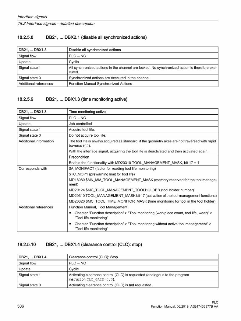
18.2.5.8 DB21, ... DBX2.1 (disable all synchronized actions)
DB21, ... DBX1.3 Disable all synchronized actionsSignal flow PLC → NCUpdate CyclicSignal state 1 All synchronized actions in the channel are locked. No synchronized action is therefore exe‐
cuted.Signal state 0 Synchronized actions are executed in the channel.Additional references Function Manual Synchronized Actions
18.2.5.9 DB21, ... DBX1.3 (time monitoring active)
DB21, ... DBX1.3 Time monitoring activeSignal flow PLC → NCUpdate Job-controlledSignal state 1 Acquire tool life.Signal state 0 Do not acquire tool life.Additional information The tool life is always acquired as standard, if the geometry axes are not traversed with rapid
traverse (G0).With the interface signal, acquiring the tool life is deactivated and then activated again.PreconditionEnable the functionality with MD20310 TOOL_MANAGEMENT_MASK, bit 17 = 1
Corresponds with $A_MONIFACT (factor for reading tool life monitoring)$TC_MOP1 (prewarning limit for tool life)MD18080 $MN_MM_TOOL_MANAGEMENT_MASK (memory reserved for the tool manage‐ment)MD20124 $MC_TOOL_MANAGEMENT_TOOLHOLDER (tool holder number)MD20310 TOOL_MANAGEMENT_MASK bit 17 (activation of the tool management functions)MD20320 $MC_TOOL_TIME_MONITOR_MASK (time monitoring for tool in the tool holder)
Additional references Function Manual, Tool Management: ● Chapter "Function description" > "Tool monitoring (workpiece count, tool life, wear)" >
"Tool life monitoring"● Chapter "Function description" > "Tool monitoring without active tool management" >
"Tool life monitoring"
18.2.5.10 DB21, ... DBX1.4 (clearance control (CLC): stop)
DB21, ... DBX1.4 Clearance control (CLC): StopSignal flow PLC → NCUpdate CyclicSignal state 1 Activating clearance control (CLC) is requested (analogous to the program
instruction CLC_GAIN=0.0).Signal state 0 Activating clearance control (CLC) is not requested.
Interface signals18.2 Interface signals - detailed description
PLC506 Function Manual, 06/2019, A5E47433877B AA

DB21, ... DBX1.4 Clearance control (CLC): StopCorresponds with CLC_GAIN=0.0 ; deactivate control loop gain
DB21, ... DBX37.3 (clearance control (CLC) active)Additional references Function Manual, Special Functions; Chapter "TE1: Clearance control"
18.2.5.11 DB21, ... DBX1.5 (clearance control (CLC): Override)
DB21, ... DBX1.5 Clearance control (CLC): OverrideSignal flow PLC → NCUpdate CyclicSignal state 1 The channel-specific feedrate override (DB21, … DBB4) should be active for clearance con‐
trol (CLC).Signal state 0 The channel-specific feedrate override (DB21, … DBB4) should not be active for clearance
control (CLC).Additional information For signal state 1, the channel-specific feedrate override acts on the maximum velocity of the
clearance control motion (MD62516):● Override settings < 100%
The velocity limit set in MD62516 for clearance control is appropriately reduced.● Override settings > 100%
The limit value from MD62516 is active.Signal state 0 is the maximum velocity of the clearance control motion, independent of the override setting.
Corresponds with DB21, ... DBB4 (feed rate override) DB21, ... DBX6.7 (feed override active)DB21, ... DBX37.3 (clearance control (CLC) active)MD62516 $MC_CLC_SENSOR_VELO_LIMIT (velocity of clearance control motion)
Additional references Function Manual, Special Functions; Chapter "TE1: Clearance control"
18.2.5.12 DB21, ... DBX1.6 (PLC action completed)
DB21, ... DBX1.6 PLC action completedSignal flow PLC → NCUpdate CyclicSignal state 1 PLC action completed.Signal state 0 PLC action is not yet completed.
Interface signals18.2 Interface signals - detailed description
PLCFunction Manual, 06/2019, A5E47433877B AA 507

DB21, ... DBX1.6 PLC action completedAdditional information Note
At the end of the block search, concluding action blocks are executed:DB21, ... DBX32.3 (action block active) == 1 ANDDB21, ... DBX32.6 (last action block active) == 1Alarm "10208 Channel <Channel Number> Issue NC Start to continue program" notifies that a new NC Start is required to continue the NC program from the target block.If other actions are to be executed by the PLC user program prior to the NC Start (e.g. tool change), by parameterizing the search mode, the output of the alarm can be delayed until the signal is set again:MD11450 $MN_SEARCH_RUN_MODE = 1
Corresponds with DB21, ... DBX7.1 (NC Start)DB21, ... DBX32.3 (action block active)DB21, ... DBX32.6 (last action block active)DB21, ... DBX33.4 (block search active)
Additional references Basic Functions Function Manual; Chapter "K1: mode group, channel, program mode, reset response"; ● Chapter, "Block search, types 1, 2, and 4"● Chapter, "Block search type 5 (SERUPRO)"
18.2.5.13 DB21, ... DBX1.7 (activate program test (PRT))
DB21, ... DBX1.7 Activate program test (PRT)Signal flow PLC → NCUpdate CyclicSignal state 1 Activation of program test (PRT) is requested.Signal state 0 Activation of program test (PRT) is not requested.
Interface signals18.2 Interface signals - detailed description
PLC508 Function Manual, 06/2019, A5E47433877B AA
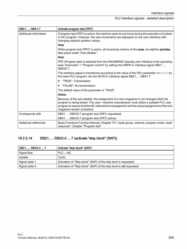
DB21, ... DBX1.7 Activate program test (PRT)Additional information If program test (PRT) is active, the machine axes do not move during the execution of a block
or NC program. However, the axis movements are displayed on the user interface with changing setpoint position values.NoteWhile program test (PRT) is active, all traversing motions of the axes, but not the spindles, take place under "Axis disable." NotePRT (Program test) is selected from the SINUMERIK Operate user interface in the operating area "Automatic" > "Program control" by setting the HMI/PLC interface signal DB21, ... DBX25.7. The interface signal is transferred according to the value of the FB1 parameter MMCToIf by the basic PLC program into the NC/PLC interface signal DB21, ... DBX1.7:● "TRUE": Transmission● "FALSE": No transmissionThe default value of the parameter is "TRUE".NoticeBecause of the axis disable, the assignment of a tool magazine is not changed while the program is being tested. The user / machine manufacturer must utilize a suitable PLC user program to ensure that the NC-internal tool management and the actual assignment of the tool magazine remain consistent.
Corresponds with DB21, ... DBX25.7 (program test (PRT) requested)DB21, ... DBX33.7 (program test (PRT) active)
Additional references Basic Functions Function Manual; Chapter "K1: mode group, channel, program mode, reset response"; Chapter "Program test"
18.2.5.14 DB21, ... DBX2.0 ... 7 (activate "skip block" (SKP))
DB21, ... DBX2.0 ... 7 Activate "skip block" (SKP)Signal flow PLC → NCUpdate CyclicSignal state 1 Activation of "Skip block" (SKP) of the skip level is requested.Signal state 0 Activation of "Skip block" (SKP) of the skip level is not requested.
Interface signals18.2 Interface signals - detailed description
PLCFunction Manual, 06/2019, A5E47433877B AA 509

DB21, ... DBX2.0 ... 7 Activate "skip block" (SKP)Additional information Bit 0 ... bit 7 are assigned to the skip levels 0 ... 7.
NoteWe recommend that the interface signal is already set before the NC program starts.NoteFor multiple consecutive skip blocks, the blocks are only skipped if the interface signal was already present before the first skip block of the block sequence was decoded. Note"Skip block" (SKP) is selected from the SINUMERIK Operate user interface in the operating area "Automatic" > "Program control" by setting the HMI/PLC interface signal DB21, ... DBX26.0 ...7. The interface signal is transferred according to the value of the FB1 parameter MMCToIf by the basic PLC program into the NC/PLC interface signal DB21, ... DBX2.0 ... 7:● "TRUE": Transmission● "FALSE": No transmissionThe default value of the parameter is "TRUE".
Corresponds with DB21, ... DBX26.0 - 7 ("Skip block" (SKP) selected)Additional references Basic Functions Function Manual; Chapter "K1: mode group, channel, program mode, reset
response"
18.2.5.15 DB21, ... DBX3.0 (stroke enable)
DB21, ... DBX3.0 Stroke enableSignal flow PLC → NCSignal state 1 Execution of punch strokes is enabled.Signal state 0 Execution of punch strokes is locked.Additional information This signal releases the punching strokes via the PLC. It is not permissible that the NC initiates
a punch stroke if the signal is not set. The NC waits until the enable signal is available before continuing the part program.
Additional references Function Manual, Extended Functions; Chapter "N4: Punching and nibbling"
18.2.5.16 DB21, ... DBX3.1 (punch interface 1: Manual stroke initiation)
DB21, ... DBX3.1 Punch interface 1: Manual stroke initiation Signal flow PLC → NCSignal state 1 Execute manual punch stroke at the 1st punch interface.Signal state 0 There is no request to initiate a manual punch stroke at the 1st punch interface.Additional information This signal allows a single stroke in the manual mode to be initiated at the 1st punch interface.
In principle, this is possible in every operating mode, assuming that the axes do not move. The signal is ignored if the axes are moved during the manual stroke initiation. During the stroke, the axes are inhibited, i.e. they can only be moved again after the "Stroke initiation active" signal has been withdrawn.
Interface signals18.2 Interface signals - detailed description
PLC510 Function Manual, 06/2019, A5E47433877B AA
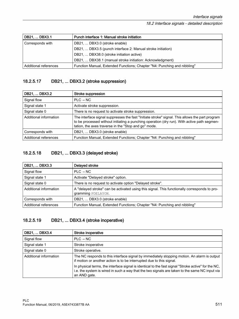
DB21, ... DBX3.1 Punch interface 1: Manual stroke initiation Corresponds with DB21, ... DBX3.0 (stroke enable)
DB21, ... DBX3.5 (punch interface 2: Manual stroke initiation)DB21, ... DBX38.0 (stroke initiation active)DB21, ... DBX38.1 (manual stroke initiation: Acknowledgment)
Additional references Function Manual, Extended Functions; Chapter "N4: Punching and nibbling"
18.2.5.17 DB21, ... DBX3.2 (stroke suppression)
DB21, ... DBX3.2 Stroke suppressionSignal flow PLC → NCSignal state 1 Activate stroke suppression.Signal state 0 There is no request to activate stroke suppression.Additional information The interface signal suppresses the fast "Initiate stroke" signal. This allows the part program
to be processed without initiating a punching operation (dry run). With active path segmen‐tation, the axes traverse in the "Stop and go" mode.
Corresponds with DB21, ... DBX3.0 (stroke enable)Additional references Function Manual, Extended Functions; Chapter "N4: Punching and nibbling"
18.2.5.18 DB21, ... DBX3.3 (delayed stroke)
DB21, ... DBX3.3 Delayed strokeSignal flow PLC → NCSignal state 1 Activate "Delayed stroke" option.Signal state 0 There is no request to activate option "Delayed stroke".Additional information A "delayed stroke" can be activated using this signal. This functionally corresponds to pro‐
gramming PDELAYON.Corresponds with DB21, ... DBX3.0 (stroke enable)Additional references Function Manual, Extended Functions; Chapter "N4: Punching and nibbling"
18.2.5.19 DB21, ... DBX3.4 (stroke inoperative)
DB21, ... DBX3.4 Stroke inoperativeSignal flow PLC → NCSignal state 1 Stroke inoperativeSignal state 0 Stroke operative.Additional information The NC responds to this interface signal by immediately stopping motion. An alarm is output
if motion or another action is to be interrupted due to this signal.In physical terms, the interface signal is identical to the fast signal "Stroke active" for the NC, i.e. the system is wired in such a way that the two signals are taken to the same NC input via an AND gate.
Interface signals18.2 Interface signals - detailed description
PLCFunction Manual, 06/2019, A5E47433877B AA 511

DB21, ... DBX3.4 Stroke inoperativeCorresponds with DB21, ... DBX3.0 (stroke enable)Additional references Function Manual, Extended Functions; Chapter "N4: Punching and nibbling"
18.2.5.20 DB21, ... DBX3.5 (punch interface 2: Manual stroke initiation)
DB21, ... DBX3.5 Punch interface 2: Manual stroke initiationSignal flow PLC → NCSignal state 1 Perform manual punch stroke at the 2nd punch interface.Signal state 0 There is no request to initiate a manual punch stroke at the 2nd punch interface.Additional information This signal enables a single stroke to be initiated at the 2nd punch interface in manual mode.
In principle, this is possible in every operating mode, assuming that the axes do not move. The signal is ignored if the axes are moved during the manual stroke initiation. During the stroke, the axes are inhibited, i.e. they can only be moved again after the "Stroke initiation active" signal has been withdrawn.
Corresponds with DB21, ... DBX3.0 (stroke enable)DB21, ... DBX3.1 (punch interface 1: Manual stroke initiation)DB21, ... DBX38.0 (stroke initiation active)DB21, ... DBX38.1 (manual stroke initiation: Acknowledgment)
Additional references Function Manual, Extended Functions; Chapter "N4: Punching and nibbling"
18.2.5.21 DB21, ... DBB4 (path feedrate override)
DB21, ... DBB4 Path feedrate overrideSignal flow PLC → NCUpdate Cyclic
Interface signals18.2 Interface signals - detailed description
PLC512 Function Manual, 06/2019, A5E47433877B AA

DB21, ... DBB4 Path feedrate overrideAdditional information Binary/Gray coding
The override factors can be specified in the binary or Gray-coded format. The control must be informed of the used format via the following machine data:MD12020 $MN_OVR_FEED_IS_GRAY_CODE = <Coding>Binary codingWith binary coding, the value in the interface corresponds to the override factor.
Binary code Decimal Override factor0000 0000 0 0.000000 0001 1 0.010000 0010 2 0.020000 0011 3 0.03000 0100 4 0.04
... ... ...0110 0100 100 1.00
... ... ...1100 1000 200 2.00
Gray codingThe Gray-coded values of the interface are assigned the override factors via the following machine data:MD12030 $MN_OVR_FACTOR_FEEDRATE[ <Switch position> - 1 ] = <Override factor>Switch position Gray code Override factor 1)
1 00001 0.002 00011 0.013 00010 0.024 00110 0.045 00111 0.066 00101 0.087 00100 0.108 01100 0.209 01101 0.3010 01111 0.4011 01110 0.5012 01010 0.6013 01011 0.7014 01001 0.7515 01000 0.8016 11000 0.8517 11001 0.9018 11011 0.9519 11010 1.0020 11110 1.0521 11111 1.1022 11101 1.15
Interface signals18.2 Interface signals - detailed description
PLCFunction Manual, 06/2019, A5E47433877B AA 513

DB21, ... DBB4 Path feedrate override23 11100 1.2024 10100 1.2025 10101 1.2026 10111 1.2027 10110 1.2028 10010 1.2029 10011 1.2030 10001 1.2031 10000 1.20
Limitations● The active override factor is limited internally in the control to 2.00 or 200%.● The maximum possible override factor can be limited to a value less than 200% with the
following machine data:MD12100 $MN_OVR_FACTOR_LIMIT_BIN
Corresponds to DB21, ... DBX6.7 (path feedrate override active)Additional references Basic Functions Function Manual; Section "V1: Feedrates" > "Feedrate control" > "Feedrate
override via the machine control panel"1) Default values
18.2.5.22 DB21, ... DBB5 (path rapid traverse override)
DB21, ... DBB5 Path rapid traverse overrideSignal flow PLC → NCUpdate Cyclic
Interface signals18.2 Interface signals - detailed description
PLC514 Function Manual, 06/2019, A5E47433877B AA

DB21, ... DBB5 Path rapid traverse overrideAdditional information Binary coding
With binary coding, the value in the interface corresponds to the override factor.Binary-co‐
dedDecimal Override factor
0000 0000 0 0.000000 0001 1 0.010000 0010 2 0.020000 0011 3 0.03000 0100 4 0.04
... ... ...0110 0100 100 1.00
... ... ...1100 1000 200 2.00
Gray codingThe Gray-coded values of the interface are assigned the override factors via the following machine data:MD12050 $MN_OVR_FACTOR_RAPID_TRA[ <Switch position> - 1 ] = <Override factor>Switch posi‐
tionGray code Override factor 1)
1 00001 0.002 00011 0.013 00010 0.024 00110 0.045 00111 0.066 00101 0.087 00100 0.108 01100 0.209 01101 0.3010 01111 0.4011 01110 0.5012 01010 0.6013 01011 0.7014 01001 0.7515 01000 0.8016 11000 0.8517 11001 0.9018 11011 0.9519 11010 1.0020 11110 1.0021 11111 1.0022 11101 1.0023 11100 1.0024 10100 1.00
Interface signals18.2 Interface signals - detailed description
PLCFunction Manual, 06/2019, A5E47433877B AA 515
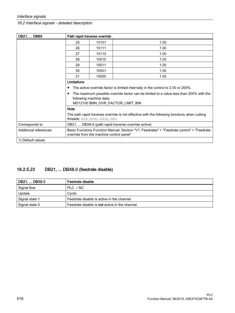
DB21, ... DBB5 Path rapid traverse override25 10101 1.0026 10111 1.0027 10110 1.0028 10010 1.0029 10011 1.0030 10001 1.0031 10000 1.00
Limitations● The active override factor is limited internally in the control to 2.00 or 200%.● The maximum possible override factor can be limited to a value less than 200% with the
following machine data:MD12100 $MN_OVR_FACTOR_LIMIT_BIN
NoteThe path rapid traverse override is not effective with the following functions when cutting threads: G33, G331, G332, G63
Corresponds to DB21, ... DBX6.6 (path rapid traverse override active)Additional references Basic Functions Function Manual; Section "V1: Feedrates" > "Feedrate control" > "Feedrate
override from the machine control panel"1) Default values
18.2.5.23 DB21, ... DBX6.0 (feedrate disable)
DB21, ... DBX6.0 Feedrate disableSignal flow PLC → NCUpdate CyclicSignal state 1 Feedrate disable is active in the channel.Signal state 0 Feedrate disable is not active in the channel.
Interface signals18.2 Interface signals - detailed description
PLC516 Function Manual, 06/2019, A5E47433877B AA

DB21, ... DBX6.0 Feedrate disableAdditional information ● The interface signal is active for all of the geometry, synchronized and positioning axes
traversing in the channel.● If the interface signal is set while traversing an axis, then the axis is braked down to
standstill along its braking characteristic. For geometry axes, the axes are braked so that they follow the contour.
● After the interface signal has been reset, traversing motion that was stopped is continued.● The position control is retained and the following error is eliminated.● If the interface signal is set, and a request is issued to traverse an axis, then the axis is not
traversed. However, the traverse request is kept. When the interface signal is reset, the traverse request is immediately executed, i.e. the axis is traversed.
● The interface signal is active in all modes.Thread cuttingDuring various thread cutting operations, the interface signal is not effective: Thread cutting Effectiveness
G33, G34, G35 Not effectiveG331, G332 EffectiveG63 Effective
Additional references Function Manual, Basic Functions; Chapter "V1: Feedrates" > "Feedrate control" > "Feedrate disable and feedrate/spindle stop"
18.2.5.24 DB21, ... DBX6.1 (read-in disable)
DB21, ... DBX6.1 Read-in disableSignal flow PLC → NCUpdate CyclicSignal state 1 A request has been made to activate the "read-in disable" function.Signal state 0 A request has not been made to activate the "read-in disable" function.Additional information If the read-in disable is set, then the data transfer for the next block is enabled in the inter‐
polator. NoteOnly active in the AUTOMATIC and MDI modes.ApplicationIf the auxiliary functions must be completed (e.g. for the tool change) before the next NC block can be processed, then the automatic block change must be prevented through the read-in disable.
Corresponds with DB21, ... DBX35.0 (program state running)Additional references Basic Functions Function Manual; Chapter "K1: mode group, channel, program mode, reset
response"
Interface signals18.2 Interface signals - detailed description
PLCFunction Manual, 06/2019, A5E47433877B AA 517

18.2.5.25 DB21, ... DBX6.2 (delete distance-to-go, channel-specific)
DB21, ... DBX6.2 Delete distance-to-go (channel-specific)Signal flow PLC→ NCUpdate CyclicEdge change 0 → 1 Delete distance-to-go (channel-specific) is requested.
Geometry axesFor a rising edge of the signal, the geometry axes currently traversing in the block are brought to a standstill along a braking ramp and then the distance-to-go is deleted. Any remaining following error is still corrected. The next traversing block is then loaded.Path axes"Delete distance-to-go" for path axes acts only in the AUTOMATIC mode.Note"Delete distance-to-go" causes the next traversing block to be prepared with the new posi‐tions. After a "Delete distance-to-go", the geometry axes thus follow a different contour to the one originally programmed in the NC program.Traversal to absolute positions (G90) in the block after "Delete distance-to-go" causes at least exact approach to the block end position. For incremental traversing (G91), the position specified in the NC program is not approached in the following block.
Edge change 1 → 0 No effectAdditional information Signal irrelevant for
● Positioning axes● Dwell timeApplication exampleTermination of the traversing motion on account of an external signal (e.g. probe)
Corresponds with DB31, ... DBX2.2 (delete distance-to-go (axis-specific))
18.2.5.26 DB21, ... DBX6.4 (program level abort)
DB21, ... DBX6.4 Program level abortSignal flow PLC → NCUpdate CyclicSignal state 0 → 1 Request to abort program processing of the actual program level (subprogram level, ASUB
level, data save routine).Signal state 1 → 0 Reset of the last request.Additional information After a program level abort, the calling program of the next higher program level is processed
further from the call location.The main program level cannot be aborted with the program level abort, but only with a channel reset.
Corresponds with DB21, ... DBX7.7 (reset)Additional references Basic Functions Function Manual; Chapter "K1: mode group, channel, program mode, reset
response"
Interface signals18.2 Interface signals - detailed description
PLC518 Function Manual, 06/2019, A5E47433877B AA

18.2.5.27 DB21, ... DBX6.6 (path rapid traverse override active)
DB21, ... DBX6.6 Path rapid traverse override activeSignal flow PLC → NCUpdate CyclicSignal state 1 The path rapid traverse override (DB21, ... DBB5) is active.Signal state 0 The path rapid traverse override is not active.Additional information If the path rapid traverse override is not active, then irrespective of the current switch position,
a value of 1.0 ≙ 100% is used as factor in the control. The first switch position is an exception. Depending on the selected coding, the following factor is active for the first switch position:● Binary coding: 0● Gray coding: MD12050 $MN_OVR_FACTOR_RAPID_TRA[ 0 ]
Corresponds to DB21, ... DBB5 (path rapid traverse override)MD12020 $MN_OVR_FEED_IS_GRAY_CODE (path feed override switch Gray-coded)MD12030 $MN_OVR_FACTOR_FEEDRATE (evaluation of the path feedrate override switch)
Additional references Basic Functions Function Manual; Section "V1: Feedrates" > "Feedrate control" > "Feedrate override from the machine control panel"
18.2.5.28 DB21, ... DBX6.7 (path feedrate override active)
DB21, ... DBX6.7 Path feedrate override activeSignal flow PLC → NCUpdate CyclicSignal state 1 The path feedrate override (DB21, ... DBB4) is active.Signal state 0 The path feedrate override is not active.Additional information If the path feedrate override is not active, then irrespective of the current switch position, a
value of 1.0 ≙ 100% is used as override factor in the control. The first switch position is an exception. Depending on the selected coding, for the first switch position the following applies:● Binary coding: Override factor = 0● Gray coding: Override factor = MD12030 $MN_OVR_FACTOR_FEEDRATE[ 0 ]
Corresponds to DB21, ... DBB4 (path feedrate override)MD12020 $MN_OVR_FEED_IS_GRAY_CODE (path feed override switch Gray-coded)MD12030 $MN_OVR_FACTOR_FEEDRATE (evaluation of the path feedrate override switch)
Additional references Basic Functions Function Manual; Section "V1: Feedrates" > "Feedrate control" > "Feedrate override from the machine control panel"
18.2.5.29 DB21, ... DBX7.0 (NC start disable)
DB21, ... DBX7.0 NC start disableSignal flow PLC → NCUpdate CyclicSignal state 1 A request has been made to activate the "NC start disable" function.Signal state 0 A request has not been made to activate the "NC start disable" function.
Interface signals18.2 Interface signals - detailed description
PLCFunction Manual, 06/2019, A5E47433877B AA 519

DB21, ... DBX7.0 NC start disableAdditional information If the NC start disable is set, then the start (DB21, ... DBX7.1) of the NC program selected in
the channel is ignored.NoteThe NC start inhibit is not active if the part program is started by the part program com‐mand START in another channel of the mode group.Applicatione.g. to suppress new program execution because there is no lubricant.
Corresponds with DB21, ... DBX7.1 (NC Start)Additional references Basic Functions Function Manual; Chapter "K1: mode group, channel, program mode, reset
response"
18.2.5.30 DB21, ... DBX7.1 (NC Start)
DB21, ... DBX7.1 NC startSignal flow PLC → NCUpdate CyclicSignal state 0 → 1 Request to start the program selected in the channel.Signal state 1 → 0 Reset of the last request.Additional information AUTOMATIC mode: The selected NC program is started or continued, or the auxiliary func‐
tions that were saved during the program interruption are output.If data is transferred from the PLC to the NC during program state "Program interrupted," then this data is immediately cleared at NC Start.MDI mode:The blocks in the MDI block memory are executed.
Corresponds with DB21, ... DBX7.0 (NC Start disable)DB21, ... DBX7.3 (NC Stop)DB21, ... DBX7.7 (reset)
Additional references Function Manual, Basic Functions; ● Chapter "K1: mode group, channel, program mode, reset response"● Chapter, "Program mode " > "Channel state"● Chapter, "Program mode " > "Program state"
18.2.5.31 DB21, ... DBX7.2 (NC Stop at the block limit)
DB21, ... DBX7.2 NC Stop at block limitSignal flow PLC → NCUpdate CyclicSignal state 1 NC stop at the end of the actual block is requested.Signal state 0 NC stop at the end of the actual block is not requested.Additional information The actual block is executed to the end of the block. Program execution is then stopped:
● Channel state: "Interrupted"● Program state: "Stopped"
Interface signals18.2 Interface signals - detailed description
PLC520 Function Manual, 06/2019, A5E47433877B AA

DB21, ... DBX7.2 NC Stop at block limitCorresponds with DB21, ... DBX7.1 (NC Start)
DB21, ... DBX7.3 (NC Stop)DB21, ... DBX7.4 (NC Stop axes plus spindles)DB21, ... DBX35.2 (program state stopped)DB21, ... DBX35.6 (interrupted channel state)
Additional references Function Manual, Basic Functions; ● Chapter "K1: mode group, channel, program mode, reset response"● Chapter, "Program mode " > "Channel state"● Chapter, "Program mode " > "Program state"
18.2.5.32 DB21, ... DBX7.3 (NC Stop)
DB21, ... DBX7.3 NC stopSignal flow PLC → NCUpdate CyclicSignal state 1 NC Stop is requested.Signal state 0 NC Stop is not requested.Additional information AUTOMATIC or MDI mode
Execution of the active part program in the channel is stopped. The traversing axes (not spindles) are braked down to standstill with the parameterized ac‐celeration rates.● Channel state: Interrupted● Program state: StoppedJOG modeIn the JOG mode, incompletely traversed incremental paths (INC...) are executed at the next NC Start (DB21, ... DBX7.1).NoteIf data is transferred to the NC after "NC Stop" (e.g. tool offset), the data is taken into account with the next "NC start".
Corresponds with DB21, ... DBX7.1 (NC Start)DB21, ... DBX7.4 (NC Stop axes plus spindles)DB21, ... DBX35.2 (program state stopped)DB21, ... DBX35.6 (interrupted channel state)
Additional references Function Manual, Basic Functions; ● Chapter "K1: mode group, channel, program mode, reset response"● Chapter, "Program mode " > "Channel state"● Chapter, "Program mode " > "Program state"
Interface signals18.2 Interface signals - detailed description
PLCFunction Manual, 06/2019, A5E47433877B AA 521

18.2.5.33 DB21, ... DBX7.4 (NC Stop axes plus spindles)
DB21, ... DBX7.4 NC Stop axes plus spindlesSignal flow PLC → NCUpdate CyclicSignal state 1 NC Stop is requested.Signal state 0 NC Stop is not requested.Additional information AUTOMATIC or MDI mode
Execution of the active part program in the channel is stopped. The traversing axes and spindles are braked down to standstill with the parameterized ac‐celeration rates.● Channel state: Interrupted● Program state: StoppedJOG modeIn the JOG mode, incompletely traversed incremental paths (INC...) are executed at the next NC Start (DB21, ... DBX7.1).NoteIf data is transferred to the NC after "NC Stop" (e.g. tool offset), the data is taken into account with the next "NC start".
Corresponds with DB21, ... DBX7.1 (NC Start)DB21, ... DBX7.3 (NC Stop)DB21, ... DBX35.2 (program state stopped)DB21, ... DBX35.6 (interrupted channel state)
Additional references Function Manual, Basic Functions; ● Chapter "K1: mode group, channel, program mode, reset response"● Chapter, "Program mode " > "Channel state"● Chapter, "Program mode " > "Program state"
18.2.5.34 DB21, ... DBX7.7 (reset)
DB21, ... DBX7.7 ResetSignal flow PLC → NCUpdate CyclicSignal state 1 Channel reset is requested.Signal state 0 Channel reset is not requested.
Interface signals18.2 Interface signals - detailed description
PLC522 Function Manual, 06/2019, A5E47433877B AA

DB21, ... DBX7.7 ResetAdditional information Responses:
● All traversing axes and spindles are decelerated without contour violation to zero speed according to their acceleration curves.
● All channel-specific reset positions become active.● All alarms of the channel, other than Power On alarms, are deleted.● Channel state: "Reset" (DB21, ... DBX35.7 == 1)● Program state of an active NC program: "Aborted" (DB21, ... DBX35.4 == 1)NoteAfter a channel reset from the PLC user program, before a new action can be requested in the channel (e.g. NC start or axis interchange), the system must wait for the channel state "reset" to be indicated at the NC/PLC interface.DB21, ... DBX35.7 == 1
Corresponds with DB11, ... DBX0.7 (mode group reset)DB21, ... DBX7.1 (NC Start)DB21, ... DBX7.3 (NC Stop)DB21, ... DBX35.4 (program state "aborted")DB21, ... DBX35.7 (channel state "reset")
Additional references Basic Functions Function Manual; Chapter "K1: mode group, channel, program mode, reset response"
18.2.5.35 DB21, ... DBX8.0 - 9.1 (activate machine-related protection zone 1 - 10)
DB21, ... DBX8.0 - 9.1 Activate machine-related protection zone 1 - 10 Signal flow PLC → NCUpdate CyclicSignal state 1 Request to activate the machine-related protection zone
The protection zone is immediately active.NoteActivating the protection zone is only effective if it was already preactivated via an NC pro‐gram.
Signal state 0 Request to deactivate the active machine-related protection zone.The protection zone is immediately inactive.NoteDeactivating the protection zone is only active if it was preactivated via an NC program and was activated via the interface signal.
Corresponds with DB21, ... DBX1.1 (enable protection zones)DB21, ... DBX8.0 - 9.1 (activate machine-related protection zone 1 - 10)DB21, ... DBX10.0 - 11.1 (activate channel-specific protection zone 1 - 10)DB21, ... DBX272.0 - 273.1 (machine-related protection zone 1 - 10 preactivated)DB21, ... DBX274.0 – 275.1 (channel-specific protection zone 1 - 10 preactivated)DB21, ... DBX276.0 - 277.1 (machine-related protection zone 1 - 10 violated)DB21, ... DBX278.0 – 279.1 (channel-specific protection zone 1 - 10 violated)
Additional references Basic Functions Function Manual; Chapter "A5: Protection zones"
Interface signals18.2 Interface signals - detailed description
PLCFunction Manual, 06/2019, A5E47433877B AA 523

18.2.5.36 DB21, ... DBX10.0 - 11.1 (activate channel-specific protection zone 1 - 10)
DB21, ... DBX10.0 - 11.1 Activate machine-related protection zone 1 - 10Signal flow PLC → NCUpdate CyclicSignal state 1 Request to activate the machine-related protection zone.
The protection zone is immediately active.NoteActivating the protection zone is only effective if it was already preactivated via an NC pro‐gram.
Signal state 0 Request to deactivate the machine-related protection zone.The protection zone is immediately inactive.NoteDeactivating the protection zone is only active if it was preactivated via an NC program and was activated via the interface signal.
Corresponds with DB21, ... DBX1.1 (enable protection zones)DB21, ... DBX8.0 - 9.1 (activate machine-related protection zone 1 - 10)DB21, ... DBX10.0 - 11.1 (activate channel-specific protection zone 1 - 10)DB21, ... DBX272.0 - 273.1 (machine-related protection zone 1 - 10 preactivated)DB21, ... DBX274.0 – 275.1 (channel-specific protection zone 1 - 10 preactivated)DB21, ... DBX276.0 - 277.1 (machine-related protection zone 1 - 10 violated)DB21, ... DBX278.0 – 279.1 (channel-specific protection zone 1 - 10 violated)
Additional references Basic Functions Function Manual; Chapter "A5: Protection zones"
18.2.5.37 DB21, ... DBX12.0 - 2 (geometry axis 1: activate handwheel)
DB21, ... DBX12.0 - 2 Geometry axis 1: Activate handwheelSignal flow PLC → NCUpdate Cyclic
Interface signals18.2 Interface signals - detailed description
PLC524 Function Manual, 06/2019, A5E47433877B AA

DB21, ... DBX12.0 - 2 Geometry axis 1: Activate handwheelAdditional information The interface can be interpreted either bit or binary-coded. The definition is realized using
machine data MD11324.Bit coded: maximum 3 handwheels Bit 2 Bit 1 Bit 0 Number of the assigned handwheel
0 0 0 No handwheel assignment0 0 1 10 1 0 21 0 0 3
Binary coded: maximum 6 handwheels Bit 2 Bit 1 Bit 0 Number of the assigned handwheel
0 0 0 No handwheel assignment0 0 1 10 1 0 20 1 1 31 0 0 41 0 1 51 1 0 6
NoteAt any one time, an axis can only be assigned to one handwheel. If, for bit coding, several interface signals are set simultaneously, then the following priority applies: "Handwheel 1" before "Handwheel 2" before "Handwheel 3".
Corresponds with DB21, ... DBX16.0 - 2 (geometry axis 2: activate handwheel)DB21, ... DBX20.0 - 2 (geometry axis 3: activate handwheel)DB21, ... DBX40.0 - 2 (geometry axis 1: handwheel active)DB21, ... DBX46.0 - 2 (geometry axis 2: handwheel active)DB21, ... DBX52.0 - 2 (geometry axis 3: handwheel active)MD11324 $MN_HANDWH_VDI_REPRESENTATION (representation of the handwheel num‐ber at the VDI interface)
Additional references Function Manual, Extended Functions; Chapter "H1: manual and handwheel travel"
18.2.5.38 DB21, ... DBX12.3, 16.3, 20.3 (feedrate stop, geometry axes 1 / 2 / 3)
DB21, ... DBX12.3DB21, ... DBX16.3DB21, ... DBX20.3
Feedrate stop, geometry axis 1, 2, 3
Signal flow PLC → NCUpdate CyclicSignal state 1 Feedrate disable for geometry axis is active.
Interface signals18.2 Interface signals - detailed description
PLCFunction Manual, 06/2019, A5E47433877B AA 525

DB21, ... DBX12.3DB21, ... DBX16.3DB21, ... DBX20.3
Feedrate stop, geometry axis 1, 2, 3
Signal state 0 Feedrate disable for geometry axis is not active.Additional information ● If the interface signal is set while traversing a geometry axis, then the geometry axis is
braked down to standstill along its braking characteristic.● After the interface signal has been reset, traversing motion that was stopped is continued.● The position control is retained and the following error is eliminated.● If the interface signal is set, and a request is issued to traverse an axis, then the axis is not
traversed. However, the traverse request is kept. When the interface signal is reset, the traverse request is immediately executed, i.e. the axis is traversed.
● The interface signal is only active in the JOG mode.
18.2.5.39 DB21, ... DBX12.4 (geometry axis 1: traversing key lock)
DB21, ... DBX12.4 Geometry axis 1: Traversing key lockSignal flow PLC → NCUpdate CyclicSignal state 1 The traversing key lock for the geometry axis is active.Signal state 0 The traversing key lock for the geometry axis is not active.Additional information Note
When the traversing key disable is activated while traversing, then traversing is canceled.Corresponds with DB21, ... DBX16.4 (geometry axis 2: traversing key lock)
DB21, ... DBX20.4 (geometry axis 3: traversing key lock)DB21, ... DBX12.6 - 7 (geometry axis 1: traversing keys "Plus" / "Minus")DB21, ... DBX16.6 - 7 (geometry axis 2: traversing keys "Plus" / "Minus")DB21, ... DBX20.6 - 7 (geometry axis 3: traversing keys "Plus" / "Minus")
Additional references Function Manual, Extended Functions; Chapter "H1: manual and handwheel travel"
18.2.5.40 DB21, ... DBX12.5 (geometry axis 1: rapid traverse override)
DB21, ... DBX12.5 Geometry axis 1: Rapid traverse overrideSignal flow PLC → NCUpdate CyclicSignal state 1 When manually traversing the geometry axis using the traversing keys, when the interface
signal is set, rapid traverse velocity becomes active (MD32010). Signal state 0 When manually traversing the geometry axis using the traversing keys, the entered JOG
velocity becomes active (SD41110 or MD32020).Additional information The signal is only active for continuous or incremental manual traversing in the JOG mode.
The signal is irrelevant:● for reference point approach (JOG mode)● in the AUTOMATIC and MDI modesThe rapid traverse velocity can be influenced using the rapid traverse override switch.
Interface signals18.2 Interface signals - detailed description
PLC526 Function Manual, 06/2019, A5E47433877B AA

DB21, ... DBX12.5 Geometry axis 1: Rapid traverse overrideCorresponds with DB21, ... DBX16.5 (geometry axis 2: rapid traverse override)
DB21, ... DBX20.5 (geometry axis 3: rapid traverse override)DB21, ... DBX12.6 - 7 (geometry axis 1: traversing keys "Plus" / "Minus")DB21, ... DBX16.6 - 7 (geometry axis 2: traversing keys "Plus" / "Minus")DB21, ... DBX20.6 - 7 (geometry axis 3: traversing keys "Plus" / "Minus")MD32010 $MA_JOG_VELO_RAPID (conventional rapid traverse)MD32020 $MA_JOG_VELO (conventional axis velocity)SD41110 $SN_JOG_SET_VELO (axis velocity for JOG)
Additional references Function Manual, Basic Functions; Chapter "V1: Feedrates"Function Manual, Extended Functions; Chapter "H1: manual and handwheel travel"
18.2.5.41 DB21, ... DBX12.6 - 7 (geometry axis 1: traversing keys "Plus" / "Minus")
DB21, ... DBX12.6 - 7 Geometry axis 1: traversing keys "Plus" / "Minus"Signal flow PLC → NCUpdate CyclicSignal state 1 A request has been made to traverse the geometry axis using the traversing key in
the positive/negative axis direction.Signal state 0 A request has not been made to traverse the geometry axis using the traversing key
in the positive/negative axis direction.
Interface signals18.2 Interface signals - detailed description
PLCFunction Manual, 06/2019, A5E47433877B AA 527

DB21, ... DBX12.6 - 7 Geometry axis 1: traversing keys "Plus" / "Minus"Additional information There is a request signal for every traversing key and/or axis direction:
Bit 6 Traversing key "Minus" (for traversing in the negative axis direction)Bit 7 Traversing key "Plus" (for traversing in the positive axis direction)
Depending on the active machine function, as well as the settings for jog and continuous operation (SD41050 and MD11300), different responses are initiated when the signal changes:1. Continuous manual travel in the jog mode
The geometry axis traverses in the direction concerned to the active limit switch as long as the interface signal is set to 1.
2. Continuous manual travel in continuous operationAt the first edge change 0 →1, the geometry axis starts to traverse in the relevant direction. This traversing movement still continues when the edge changes from 1 → 0. Any new signal edge change 0 → 1 (same traversing direction!) stops the traversing movement.
3. Incremental manual travel in the jog modeWith signal 1 the geometry axis starts to traverse at the set increment. If the signal changes to the 0 state before the increment is traversed, then traversing is interrupted. When the signal state changes to 1 again, traversing is continued. The geometry axis can be stopped and started several times as described above until it has traversed the complete increment.
4. Incremental manual travel in continuous operationAt the first edge change 0 → 1 the geometry axis starts to traverse at the set increment. If another edge change 0 → 1 is performed with the same traverse signal before the geometry axis has traversed the increment, the traversing movement will be cancelled. The increment is no longer traversed to the end.
Note● The interface signal is irrelevant in operating modes:
– AUTOMATIC – MDI
● If both traversing signals ("plus" and "minus") are set at the same time there is no traversing or the current traversing is aborted.
● In contrast to machine axes, for geometry axes, only one geometry axis can be traversed at any one time using the traversing keys.
● Using DB21, ... DBX12.4, 16.4, 20.4 (geometry axes 1, 2, 3: Traversing key lock) traversing using traversing keys can be locked.
● In the following cases, the geometry axis cannot be traversed in the JOG operating mode:– The geometry axis is already being traversed via the axis-specific interface
as machine axis.– If another geometry axis is already being traversed with the traversing keys.
Interface signals18.2 Interface signals - detailed description
PLC528 Function Manual, 06/2019, A5E47433877B AA

DB21, ... DBX12.6 - 7 Geometry axis 1: traversing keys "Plus" / "Minus"Corresponds with DB21, ... DBX16.6 - 7 (geometry axis 2: traversing keys "Plus" / "Minus")
DB21, ... DBX20.6 - 7 (geometry axis 3: traversing keys "Plus" / "Minus")DB21, ... DBX12.4 (geometry axis 1: traversing key lock)DB21, ... DBX16.4 (geometry axis 2: traversing key lock)DB21, ... DBX20.4 (geometry axis 3: traversing key lock)DB31, ... DBX4.6 - 7 (traversing keys "Plus" / "Minus")MD11300 $MN_JOG_INC_MODE_LEVELTRIGGRD (INC and REF in jog mode)SD41050 $SN_JOG_CONT_MODE_LEVELTRIGGRD (jog/continuous operation for JOG, continuous)
Additional references Function Manual, Extended Functions; Chapter "H1: manual and handwheel travel"
18.2.5.42 DB21, ... DBX13.0 - 6 (geometry axis 1: machine function request)
DB21, ... DBX13.0 - 6 Geometry axis 1: machine function requestSignal flow PLC → NCUpdate CyclicSignal state 1 The machine function to manually traverse the geometry axis has been requested.Signal state 0 The machine function to manually traverse the geometry axis has not been requested.Additional information There is a request signal for every machine function to manually traverse the geometry axis
in the JOG mode.Bit 0 INC1Bit 1 INC10Bit 2 INC100Bit 3 INC1000Bit 4 INC10000Bit 5 INCvarBit 6 Continuous manual travel
Incremental manual travelIn addition to five fixed increment sizes (default setting in MD11330: INC1, INC10, INC100, INC1000 and INC10000), a variable increment size (INCvar) that can be set via the setting data SD41010 is also available. The distance evaluation of one increment for fixed and vari‐able increment sizes is performed via the axis-specific machine data MD31090.When pressing the "Plus" or "Minus" traversing key, or by rotating the electronic handwheel, the geometry axis starts to traverse in the appropriate direction, corresponding to the number of increments of the active machine function.Continuous manual travelFor continuous manual travel, the plus and minus traversing keys are selected to move the geometry axis continuously and the appropriate direction. Notes● If several requests are set simultaneously, no machine function becomes active.● If a geometry axis is currently being traversed via a machine function, the movement is
aborted through deselection or change of the machine function.
Interface signals18.2 Interface signals - detailed description
PLCFunction Manual, 06/2019, A5E47433877B AA 529

DB21, ... DBX13.0 - 6 Geometry axis 1: machine function requestCorresponds with DB21, ... DBX17.0 - 6 (geometry axis 2: machine function request)
DB21, ... DBX21.0 - 6 (geometry axis 3: machine function request)DB21, ... DBX41.0 - 6 (geometry axis 1: active machine function)DB21, ... DBX47.0 - 6 (geometry axis 2: active machine function)DB21, ... DBX53.0 - 6 (geometry axis 3: active machine function)MD11320 $MN_HANDWH_IMP_PER_LATCH (handwheel pulses per detent position)MD11330 $MN_JOG_INCR_SIZE_TAB (increment size for INC/handwheel)MD31090 $MA_JOG_INCR_WEIGHT (evaluation of an increment for INC/handwheel)SD41010 $SN_JOG_VAR_INCR_SIZE (size of the variable increment for JOG)
Additional references Function Manual, Extended Functions; Chapter "H1: manual and handwheel travel"
18.2.5.43 DB21, ... DBX15.0 (geometry axis 1: invert handwheel direction of rotation)
DB21, ... DBX15.0 Geometry axis 1: invert handwheel direction of rotationSignal flow PLC → NCUpdate CyclicSignal state 1 A request has been made to invert the direction of rotation of the handwheel assigned to the
geometry axis.Signal state 0 A request has not been made to invert the direction of rotation of the handwheel assigned to
the geometry axis.Additional information Note
It is only permissible to change the interface signal when the geometry axis is at a standstill.Application examples● The direction of movement of the handwheel does not match the expected direction of the
axis.● A handwheel is assigned to several axes with different orientations.
Corresponds with DB21, ... DBX19.0 (geometry axis 2: invert handwheel direction of rotation)DB21, ... DBX23.0 (geometry axis 3: invert handwheel direction of rotation)DB21, ... DBX43.0 (geometry axis 1: handwheel direction of rotation inversion active)DB21, ... DBX49.0 (geometry axis 2: handwheel direction of rotation inversion active)DB21, ... DBX55.0 (geometry axis 3: handwheel direction of rotation inversion active)
Additional references Function Manual, Extended Functions; Chapter "H1: manual and handwheel travel"
18.2.5.44 DB21, ... DBX16.0 - 2 (geometry axis 2: activate handwheel)
DB21, ... DBX16.0 - 2 Geometry axis 2: Activate handwheelAdditional information See DB21, ... DBX12.0 - 2 (geometry axis 1: activate handwheel) (Page 524).
Interface signals18.2 Interface signals - detailed description
PLC530 Function Manual, 06/2019, A5E47433877B AA
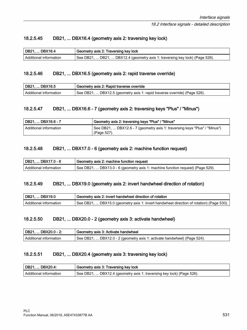
18.2.5.45 DB21, ... DBX16.4 (geometry axis 2: traversing key lock)
DB21, ... DBX16.4 Geometry axis 2: Traversing key lockAdditional information See DB21, ... DB21, ... DBX12.4 (geometry axis 1: traversing key lock) (Page 526).
18.2.5.46 DB21, ... DBX16.5 (geometry axis 2: rapid traverse override)
DB21, ... DBX16.5 Geometry axis 2: Rapid traverse overrideAdditional information See DB21, ... DBX12.5 (geometry axis 1: rapid traverse override) (Page 526).
18.2.5.47 DB21, ... DBX16.6 - 7 (geometry axis 2: traversing keys "Plus" / "Minus")
DB21, ... DBX16.6 - 7 Geometry axis 2: traversing keys "Plus" / "Minus"Additional information See DB21, ... DBX12.6 - 7 (geometry axis 1: traversing keys "Plus" / "Minus")
(Page 527).
18.2.5.48 DB21, ... DBX17.0 - 6 (geometry axis 2: machine function request)
DB21, ... DBX17.0 - 6 Geometry axis 2: machine function requestAdditional information See DB21, ... DBX13.0 - 6 (geometry axis 1: machine function request) (Page 529).
18.2.5.49 DB21, ... DBX19.0 (geometry axis 2: invert handwheel direction of rotation)
DB21, ... DBX19.0 Geometry axis 2: invert handwheel direction of rotationAdditional information See DB21, ... DBX15.0 (geometry axis 1: invert handwheel direction of rotation) (Page 530).
18.2.5.50 DB21, ... DBX20.0 - 2 (geometry axis 3: activate handwheel)
DB21, ... DBX20.0 - 2: Geometry axis 3: Activate handwheelAdditional information See DB21, ... DBX12.0 - 2 (geometry axis 1: activate handwheel) (Page 524).
18.2.5.51 DB21, ... DBX20.4 (geometry axis 3: traversing key lock)
DB21, ... DBX20.4: Geometry axis 3: Traversing key lockAdditional information See DB21, ... DBX12.4 (geometry axis 1: traversing key lock) (Page 526).
Interface signals18.2 Interface signals - detailed description
PLCFunction Manual, 06/2019, A5E47433877B AA 531

18.2.5.52 DB21, ... DBX20.5 (geometry axis 3: rapid traverse override)
DB21, ... DBX20.5 Geometry axis 3: Rapid traverse overrideAdditional information See DB21, ... DBX12.5 (geometry axis 1: rapid traverse override) (Page 526).
18.2.5.53 DB21, ... DBX20.6 - 7 (geometry axis 3: traversing keys "Plus" / "Minus")
DB21, ... DBX20.6 - 7: Geometry axis 3: traversing keys "Plus" / "Minus"Additional information See DB21, ... DBX12.6 - 7 (geometry axis 1: traversing keys "Plus" / "Minus")
(Page 527).
18.2.5.54 DB21, ... DBX21.0 - 6 (geometry axis 3: machine function request)
DB21, ... DBX21.0 - 6 Geometry axis 3: machine function requestAdditional information See DB21, ... DBX13.0 - 6 (geometry axis 1: machine function request) (Page 529).
18.2.5.55 DB21, ... DBX23.0 (geometry axis 3: invert handwheel direction of rotation)
DB21, ... DBX23.0 Geometry axis 3: invert handwheel direction of rotationAdditional information See DB21, ... DBX15.0 (geometry axis 1: invert handwheel direction of rotation) (Page 530).
18.2.5.56 DB21, ... DBX24.3 (handwheel offset (DRF) requested)
DB21, ... DBX24.3 Handwheel offset (DRF) selectedSignal flow HMI → PLCUpdate CyclicSignal state 1 Handwheel offset (DRF) is selectedSignal state 0 Handwheel offset (DRF) is not selected.Additional information As soon as handwheel offset (DRF) is active, the handwheel offset can be changed in AU‐
TOMATIC or MDI mode using the handwheel assigned to the axis.NoteHandwheel offset (DRF) is selected from the SINUMERIK Operate user interface in the op‐erating area "Automatic" > "Program control" by setting the HMI/PLC interface signal DB21, ... DBX24.3. The interface signal is transferred according to the value of the FB1 parameter MMCToIf by the basic PLC program into the NC/PLC interface signal DB21, ... DBX0.3:● "TRUE": Transmission● "FALSE": No transmissionThe default value of the parameter is "TRUE".
Corresponds with DB21, ... DBX0.3 (activate handwheel offset (DRF))Additional references Function Manual, Extended Functions; Chapter "H1: manual and handwheel travel"
Interface signals18.2 Interface signals - detailed description
PLC532 Function Manual, 06/2019, A5E47433877B AA

18.2.5.57 DB21, ... DBX24.4 (select NC-associated M01)
DB21, ... DBX24.4 Associated auxiliary function selectedSignal flow HMI → PLCUpdate Job-controlledSignal state 1 Associated auxiliary function is selected.Signal state 0 Associated auxiliary function is not selected.Additional information "Associated auxiliary function" (M-1) is selected from the SINUMERIK Operate user interface
in the operating area "Automatic" > "Program control" by setting the HMI/PLC interface signal DB21, ... DBX24.4.The interface signal is transferred according to the value of the FB1 parameter MMCToIf by the basic PLC program into the NC/PLC interface signal DB21, ... DBX30.5:● "TRUE": Transmission● "FALSE": No transmissionThe default value of the parameter is "TRUE".
Corresponds with DB21, ... DBX30.5 (activate associated auxiliary function)DB21, ... DBX318.5 (associated auxiliary function active)MD22254 $MC_AUXFU_ASSOC_M0_VALUE (additional M function for program stop)MD22256 $MC_AUXFU_ASSOC_M1_VALUE (additional M function for conditional stop)
Additional references Function Manual, Basic Functions; Chapter "H2: Auxiliary function outputs to PLC > "Asso‐ciated auxiliary functions"
18.2.5.58 DB21, ... DBX24.5 (M01 requested)
DB21, ... DBX24.5 M01 selectedSignal flow HMI → PLCUpdate CyclicSignal state 1 Program control "Conditional stop"M01 is selected.Signal state 0 Program control "Conditional stop"M01 is not selected.Additional information Program control "Conditional stop" M01 is selected from the SINUMERIK Operate user in‐
terface: Operating area "Automatic" > "Program control" by setting the HMI/PLC interface signal DB21, ... DBX24.5. The interface signal is then transferred according to the value of the FB1 parameter MMCToIf by the basic PLC program into the NC/PLC interface signal DB21, ... DBX0.5:● "TRUE": Transmission● "FALSE": No transmissionThe default value of the parameter is "TRUE".
Corresponds with DB21, ... DBX0.5 (activate M01)DB21, ... DBX32.5 (M00/M01 active)
Additional references Basic Functions Function Manual; Chapter "K1: Mode group, channel, program operation, reset response" > "Program control" > "Function selection via user interface or PLC user program"Operating Manual, HMI Advanced "Machine operating area"
Interface signals18.2 Interface signals - detailed description
PLCFunction Manual, 06/2019, A5E47433877B AA 533

18.2.5.59 DB21, ... DBX24.6 (dry run feedrate selected)
DB21, ... DBX24.6 Dry run feedrate (DRY) selectedSignal flow HMI → PLCUpdate CyclicSignal state 1 Dry run feedrate (DRY) is selected.Signal state 0 Dry run feedrate (DRY) is not selected.Additional information Note
Dry run feedrate (DRY) is selected from the SINUMERIK Operate user interface in the oper‐ating area "Automatic" > "Program control" by setting the HMI/PLC interface signal DB21, ... DBX24.6. The interface signal is transferred according to the value of the FB1 parameter MMCToIf by the basic PLC program into the NC/PLC interface signal DB21, ... DBX0.6:● "TRUE": Transmission● "FALSE": No transmissionThe default value of the parameter is "TRUE".NoteThe value for the dry run feedrate is set using:SD42100 $SC_DRY_RUN_FEED
Corresponds with DB21, ... DBX0.6 (activate dry run (DRY) feedrate)SD42100 $SC_DRY_RUN_FEED (dry run feedrate)SD42101 $SC_DRY_RUN_FEED_MODE (mode for dry run velocity)
Additional references Function Manual, Basic Functions● Chapter "K1: mode group, channel, program mode, reset response" > "Program test" >
"Program processing with dry run feedrate"● Chapter "V1: Feedrates" > "Feedrate control" > "Dry run feedrate"Operating Manual, Turning or Milling or Grinding● Chapter "Machining a workpiece" > "Controlling the program sequence" > "Program
controls"
18.2.5.60 DB21, ... DBX25.3 (feedrate override selected for rapid traverse)
DB21, ... DBX25.3 Feedrate override selected for rapid traverseSignal flow HMI → PLCUpdate CyclicSignal state 1 Feedrate override is selected for rapid traverseSignal state 0 Feedrate override is not selected for rapid traverse
Interface signals18.2 Interface signals - detailed description
PLC534 Function Manual, 06/2019, A5E47433877B AA

DB21, ... DBX25.3 Feedrate override selected for rapid traverseAdditional information If there is no dedicated rapid traverse override switch on the machine control panel, you can
then toggle between feedrate override and rapid traverse override. Rapid traverse override can be selected by selecting feedrate override for rapid traverse at the user interface. The interface signal is set:DB21, ... DBX25.3 = 1The following interface signals are set by the PLC basic program:● Rapid traverse override active = feedrate override for rapid traverse selected
DB21, ... DBX6.6 = DB21, ... DBX25.3● Rapid traverse override = feedrate override
DB21, ... DBB5 = DB21, ... DBB4Override factors> 100% are limited to 100%.NoteThe PLC user program can also initiate the switchover between rapid traverse and feedrate override. To do this, the following interface signals must be set:● Rapid traverse override active
DB21, ... DBX6.6 = 1● Rapid traverse override = feedrate override
DB21, ... DBB5 = DB21, ... DBB4Corresponds with DB21, ... DBB4 (feedrate override)
DB21, ... DBB5 (rapid traverse override)DB21, ... DBX6.6 (rapid traverse override active)
Additional references Function Manual, Basic Functions; Chapter "V1: Feedrates" > "Feedrate control" > "Feedrate override from the machine control panel"
18.2.5.61 DB21, ... DBX25.7 (program test (PRT) requested)
DB21, ... DBX25.7 Program test (PRT) selectedSignal flow HMI → PLCUpdate CyclicSignal state 1 Program test (PRT) is selectedSignal state 0 Program test (PRT) is not selected.
Interface signals18.2 Interface signals - detailed description
PLCFunction Manual, 06/2019, A5E47433877B AA 535

DB21, ... DBX25.7 Program test (PRT) selectedAdditional information If program test (PRT) is active, the machine axes do not move during the execution of a block
or NC program. However, the axis movements are displayed on the user interface with changing setpoint position values.NoteWhile program test (PRT) is active, all traversing motions take place in the channel depending on the current mode of the axis:● Axes: "Axis disable" is active ⇒ no real traversing motions● Spindles: "Axis disable" is not active ⇒ real traversing motionsNoteProgram test (PRT) is selected from the SINUMERIK Operate user interface in the operating area "Automatic" > "Program control" by setting the HMI/PLC interface signal DB21, ... DBX25.7. The interface signal is transferred according to the value of the FB1 parameter MMCToIf by the basic PLC program into the NC/PLC interface signal DB21, ... DBX1.7:● "TRUE": Transmission● "FALSE": No transmissionThe default value of the parameter is "TRUE".NoticeBecause of the axis disable, the assignment of a tool magazine is not changed while the program is being tested. The user / machine manufacturer must utilize a suitable PLC user program to ensure that the NC-internal tool management and the actual assignment of the tool magazine remain consistent.
Corresponds with DB21, ... DBX1.7 (activate program test (PRT))DB21, ... DBX33.7 (program test (PRT) active)
Additional references Basic Functions Function Manual; Chapter "K1: mode group, channel, program mode, reset response"; Chapter "Program test"
18.2.5.62 DB21, ... DBX26.0 ... 7 ("Skip block" (SKP) selected)
DB21, ... DBX26.0 ... 7 "Skip block" (SKP) selectedSignal flow PLC → NCUpdate CyclicSignal state 1 "Skip block" (SKP) of the skip level is selected.Signal state 0 "Skip block" (SKP) of the skip level is not selected.
Interface signals18.2 Interface signals - detailed description
PLC536 Function Manual, 06/2019, A5E47433877B AA

DB21, ... DBX26.0 ... 7 "Skip block" (SKP) selectedAdditional information Bit 0 ... bit 7 are assigned to the skip levels 0 ... 7.
NoteWe recommend that the interface signal is already set before the NC program starts.NoteFor multiple consecutive skip blocks, the blocks are only skipped if the interface signal was already present before the first skip block of the block sequence was decoded. Note"Skip block" (SKP) is selected from the SINUMERIK Operate user interface in the operating area "Automatic" > "Program control" by setting the HMI/PLC interface signal DB21, ... DBX26.0 ...7. The interface signal is transferred according to the value of the FB1 parameter MMCToIf by the basic PLC program into the NC/PLC interface signal DB21, ... DBX2.0 ... 7:● "TRUE": Transmission● "FALSE": No transmissionThe default value of the parameter is "TRUE".
Corresponds with DB21, ... DBX2.0 ... 7 (activate "skip block")Additional references Basic Functions Function Manual; Chapter "K1: mode group, channel, program mode, reset
response"
18.2.5.63 DB21, ... DBX29.0 - 3 (activate fixed feedrate 1 - 4, path/geometry axes)
DB 21, ... DBX29.0 - 3 Activate fixed feedrate 1 - 4, path/geometry axesSignal flow PLC → NCUpdate CyclicAdditional information With the interface signals, in the AUTOMATIC mode, instead of the programmed feedrate or
the configured JOG velocities, the fixed feedrate - parameterized using machine data - is activated.
Bit 3 Bit 2 Bit 1 Bit 0 Meaning0 0 0 0 Fixed feedrate not selected0 0 0 1 Fixed feedrate 10 0 1 0 Fixed feedrate 20 1 0 0 Fixed feedrate 31 0 0 0 Fixed feedrate 4
The fixed feedrates are parameterized using the following machine data:● Linear axes: MD12202 $MN_PERMANENT_FEED● Rotary axes: MD12204 $MN_PERMANENT_ROT_AX_FEEDNotes● The fixed feedrate is not used for:
– Spindles– Positioning axes– Tapping
● The fixed feedrate is always interpreted as linear feedrate. Switchover to linear feedrate is performed internally in the control system also when revolutional feedrate is active.
Interface signals18.2 Interface signals - detailed description
PLCFunction Manual, 06/2019, A5E47433877B AA 537
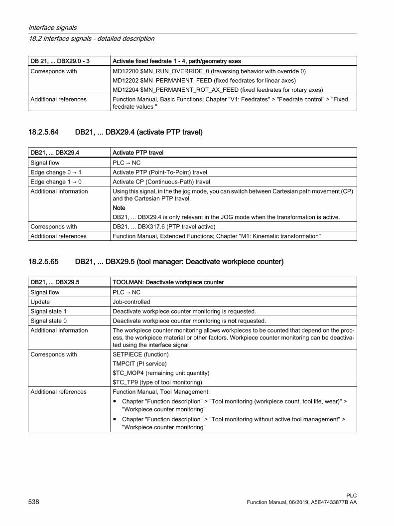
DB 21, ... DBX29.0 - 3 Activate fixed feedrate 1 - 4, path/geometry axesCorresponds with MD12200 $MN_RUN_OVERRIDE_0 (traversing behavior with override 0)
MD12202 $MN_PERMANENT_FEED (fixed feedrates for linear axes)MD12204 $MN_PERMANENT_ROT_AX_FEED (fixed feedrates for rotary axes)
Additional references Function Manual, Basic Functions; Chapter "V1: Feedrates" > "Feedrate control" > "Fixed feedrate values "
18.2.5.64 DB21, ... DBX29.4 (activate PTP travel)
DB21, ... DBX29.4 Activate PTP travelSignal flow PLC → NCEdge change 0 → 1 Activate PTP (Point-To-Point) travelEdge change 1 → 0 Activate CP (Continuous-Path) travelAdditional information Using this signal, in the the jog mode, you can switch between Cartesian path movement (CP)
and the Cartesian PTP travel.NoteDB21, ... DBX29.4 is only relevant in the JOG mode when the transformation is active.
Corresponds with DB21, ... DBX317.6 (PTP travel active)Additional references Function Manual, Extended Functions; Chapter "M1: Kinematic transformation"
18.2.5.65 DB21, ... DBX29.5 (tool manager: Deactivate workpiece counter)
DB21, ... DBX29.5 TOOLMAN: Deactivate workpiece counterSignal flow PLC → NCUpdate Job-controlledSignal state 1 Deactivate workpiece counter monitoring is requested.Signal state 0 Deactivate workpiece counter monitoring is not requested.Additional information The workpiece counter monitoring allows workpieces to be counted that depend on the proc‐
ess, the workpiece material or other factors. Workpiece counter monitoring can be deactiva‐ted using the interface signal
Corresponds with SETPIECE (function)TMPCIT (PI service)$TC_MOP4 (remaining unit quantity)$TC_TP9 (type of tool monitoring)
Additional references Function Manual, Tool Management: ● Chapter "Function description" > "Tool monitoring (workpiece count, tool life, wear)" >
"Workpiece counter monitoring"● Chapter "Function description" > "Tool monitoring without active tool management" >
"Workpiece counter monitoring"
Interface signals18.2 Interface signals - detailed description
PLC538 Function Manual, 06/2019, A5E47433877B AA

18.2.5.66 DB21, ... DBX29.6 (tool manager: Deactivating wear monitoring)
DB21, ... DBX29.6 TOOLMAN: Deactivate wear monitoringSignal flow PLC → NCUpdate Job-controlledSignal state 1 Deactivate wear monitoring is requested.Signal state 0 Deactivate wear monitoring is not requested.Corresponds with $TC_MOP15 (wear setpoint or additive offset value)
$TC_MOP5 (wear pre-warning limit or additive offset pre-warning limit)$TC_MOP6 (wear value or additive offset setpoint)$TC_TP9 (type of tool monitoring)MD18080 $MN_MM_TOOL_MANAGEMENT_MASK (memory reserved for the tool manage‐ment)MD20310 TOOL_MANAGEMENT_MASK bit 17 (activation of the tool management functions)
Additional references Function Manual, Tool Management: ● Chapter "Function description" > "Tool monitoring (workpiece count, tool life, wear)" >
"Wear monitoring"● Chapter "Function description" > "Tool monitoring without active tool management" >
"Wear monitoring"
18.2.5.67 DB21, ... DBX29.7 (tool manager: Tool lock not active)
DB21, ... DBX29.7 TOOLMAN: Tool lock not activeSignal flow PLC → NCUpdate Job-controlledSignal state 1 Tool lock notactive.Signal state 0 Tool lock is activeAdditional information A tool assumes the "locked" state if the actual value of the active monitoring function (work‐
piece count, tool life or wear) has reached a value of zero. If the tool is still being used, then it remains in use (for machining) until the next tool change. After that the tool can no longer be used. Using the interface signal, it can be set that the NC does not take the "locked" state into account when searching for a tool that can be used.The interface signal is not active if the tool selection is realized using in it blocks (reset and start mode mask).
Corresponds with MD22562 $MC_TOOL_CHANGE_ERROR_MODE (response for tool change errors)Additional references Function Manual, Tool Management; Chapter "Function description" > "Tool monitoring
(workpiece count, tool life, wear)" > "Wear monitoring" > "Signals to the PLC and from the PLC"
Interface signals18.2 Interface signals - detailed description
PLCFunction Manual, 06/2019, A5E47433877B AA 539

18.2.5.68 DB21 ... DBX30.0 - 2 (activate contour handwheel)
DB21, ... DBX30.0 - 2: Activate contour handwheelSignal flow PLC → NCUpdate CyclicAdditional information The interface can be interpreted either bit or binary-coded. The definition is realized using
machine data MD11324.Bit coded: maximum 3 handwheels Bit 2 Bit 1 Bit 0 Number of the assigned handwheel
0 0 0 No handwheel assignment0 0 1 10 1 0 21 0 0 3
Binary coded: maximum 6 handwheels Bit 2 Bit 1 Bit 0 Number of the assigned handwheel
0 0 0 No handwheel assignment0 0 1 10 1 0 20 1 1 31 0 0 41 0 1 51 1 0 6
NoteAt any one time, an axis can only be assigned to one handwheel. If, for bit coding, several interface signals are set simultaneously, then the following priority applies: "Handwheel 1" before "Handwheel 2" before "Handwheel 3".
Corresponds with DB21, ... DBX37.0 - 2 (contour handwheel active)MD11324 $MN_HANDWH_VDI_REPRESENTATION (representation of the handwheel num‐ber at the VDI interface)
Additional references Function Manual, Extended Functions; Chapter "H1: manual and handwheel travel"
18.2.5.69 DB21, ... DBX30.3 (simulation contour handwheel: Activate)
DB21, ... DBX30.3 Simulation contour handwheel: ActivationSignal flow PLC → NCUpdate CyclicSignal state 1 Activate contour handwheel simulationSignal state 0 Deactivate contour handwheel simulationAdditional information During simulation, the feedrate is no longer defined by the contour handwheel, but traversing
occurs with the programmed feedrate on the contour. When deactivated, the actual traversing motion is braked along the braking ramp.NoteSimulation is only effective in AUTOMATIC mode and can only be activated when the contour handwheel is activated.
Interface signals18.2 Interface signals - detailed description
PLC540 Function Manual, 06/2019, A5E47433877B AA
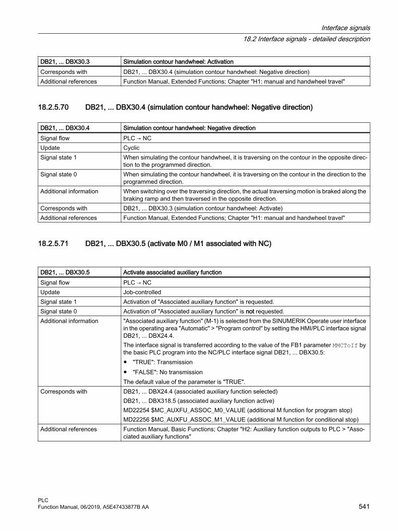
DB21, ... DBX30.3 Simulation contour handwheel: ActivationCorresponds with DB21, ... DBX30.4 (simulation contour handwheel: Negative direction)Additional references Function Manual, Extended Functions; Chapter "H1: manual and handwheel travel"
18.2.5.70 DB21, ... DBX30.4 (simulation contour handwheel: Negative direction)
DB21, ... DBX30.4 Simulation contour handwheel: Negative directionSignal flow PLC → NCUpdate CyclicSignal state 1 When simulating the contour handwheel, it is traversing on the contour in the opposite direc‐
tion to the programmed direction.Signal state 0 When simulating the contour handwheel, it is traversing on the contour in the direction to the
programmed direction.Additional information When switching over the traversing direction, the actual traversing motion is braked along the
braking ramp and then traversed in the opposite direction.Corresponds with DB21, ... DBX30.3 (simulation contour handwheel: Activate)Additional references Function Manual, Extended Functions; Chapter "H1: manual and handwheel travel"
18.2.5.71 DB21, ... DBX30.5 (activate M0 / M1 associated with NC)
DB21, ... DBX30.5 Activate associated auxiliary functionSignal flow PLC → NCUpdate Job-controlledSignal state 1 Activation of "Associated auxiliary function" is requested.Signal state 0 Activation of "Associated auxiliary function" is not requested.Additional information "Associated auxiliary function" (M-1) is selected from the SINUMERIK Operate user interface
in the operating area "Automatic" > "Program control" by setting the HMI/PLC interface signal DB21, ... DBX24.4.The interface signal is transferred according to the value of the FB1 parameter MMCToIf by the basic PLC program into the NC/PLC interface signal DB21, ... DBX30.5:● "TRUE": Transmission● "FALSE": No transmissionThe default value of the parameter is "TRUE".
Corresponds with DB21, ... DBX24.4 (associated auxiliary function selected)DB21, ... DBX318.5 (associated auxiliary function active)MD22254 $MC_AUXFU_ASSOC_M0_VALUE (additional M function for program stop)MD22256 $MC_AUXFU_ASSOC_M1_VALUE (additional M function for conditional stop)
Additional references Function Manual, Basic Functions; Chapter "H2: Auxiliary function outputs to PLC > "Asso‐ciated auxiliary functions"
Interface signals18.2 Interface signals - detailed description
PLCFunction Manual, 06/2019, A5E47433877B AA 541

18.2.5.72 DB21, ... DBX30.6 (JOG circular travel)
DB21, ... DBX30.6 JOG circular travelSignal flow PLC → NCUpdate CyclicSignal state 1 The "Circular travel in JOG" function is requested.Signal state 0 The "Circular travel in JOG" function is not requested.Additional information As soon as the function is active (see DB21, ... DBX377.6), the machine operator can simul‐
taneously traverse the two geometry axes of the active plane along an arc using the traverse keys or handwheel.ApplicationThis function is used for machine tools that are exclusively operated manually.NoteThe following preconditions applying for the "Circular travel in JOG" function:● The "Circular travel in JOG" function can be activated only in the JOG mode.
The function cannot be activated if the machine functions JOG-REPOS and JOG-REF are active.
● The axes that participate in traversing must be referenced.● It is not permissible that the active plane is inclined in space.
Corresponds with DB21, ... DBX377.6 (JOG circular travel active)Additional references Function Manual, Extended Functions; Chapter "H1: manual and handwheel travel"
18.2.5.73 DB21, ... DBX31.0 - 2 (REPOS mode)
DB21, ... DBX31.0 - 2 REPOS modeSignal flow PLC → NCUpdate CyclicAdditional information Selecting the REPOS mode:
Bit 2 Bit 1 Bit 0 REPOS mode0 0 0 No REPOS mode active0 0 1 RMB: Repositioning to start of block0 1 0 RMI: Repositioning to interrupt point0 1 1 RME: Repositioning to end of block1 0 0 RMN: Repositioning to the nearest point on the path
Interface signals18.2 Interface signals - detailed description
PLC542 Function Manual, 06/2019, A5E47433877B AA

DB21, ... DBX31.0 - 2 REPOS modeCorresponds with DB21, ... DBX25.4 (REPOS mode activation)
DB21, ... DBX31.4 (REPOS mode change)DB31, ... DBX10.0 (REPOS delay)DB31, ... DBX72.0 (REPOS delay)DB21, ... DBX319.0 (REPOS mode change acknowledgment)DB21, ... DBX319.1 - 3 (active REPOS mode)DB21, ... DBX319.5 (REPOS acknowledgment delay)DB31, ... DBX70.0 (REPOS offset)DB31, ... DBX70.1 (REPOS offset valid)DB31, ... DBX70.2 (REPOS delay acknowledgment)MD11470 $MN_REPOS_MODE_MASK (repositioning properties)
Additional references Basic Functions Function Manual; Chapter "K1: mode group, channel, program mode, reset response"
18.2.5.74 DB21, ... DBX31.4 (REPOS activation)
DB21, ... DBX31.4 REPOS activationSignal flow PLC → NCUpdate CyclicSignal state 0 → 1 Request to activate the "REPOS" function for the actual main run block.
The following become active:● DB21, ... DBX31.0 - 2 (REPOS mode)● DB31, ... DBX10.0 (REPOS delay)
Signal state 1 → 0 Reset of the last request.Corresponds with DB21, ... DBX25.4 (REPOS mode activation)
DB21, ... DBX31.0 - 2 (REPOS mode)DB31, ... DBX10.0 (REPOS delay)DB31, ... DBX72.0 (REPOS delay)DB21, ... DBX319.0 (REPOS mode change acknowledgment)DB21, ... DBX319.1 - 3 (active REPOS mode)DB21, ... DBX319.5 (REPOS acknowledgment delay)DB31, ... DBX70.0 (REPOS offset)DB31, ... DBX70.1 (REPOS offset valid)DB31, ... DBX70.2 (REPOS delay acknowledgment)MD11470 $MN_REPOS_MODE_MASK (repositioning properties)
Additional references Function Manual, Basic Functions; ● Chapter "B1: Continuous-path mode, exact stop, LookAhead" > "Smoothing and
repositioning (REPOS)"● Chapter "K1: Mode group, channel, program mode, reset response" > "Repositioning to
the contour (REPOS)"
Interface signals18.2 Interface signals - detailed description
PLCFunction Manual, 06/2019, A5E47433877B AA 543

18.2.5.75 DB21, ... DBX31.5 (contour handwheel: invert handwheel direction of rotation)
DB21, ... DBX31.5 Contour handwheel: invert handwheel direction of rotationSignal flow PLC → NCUpdate CyclicSignal state 1 A request has been made to invert the direction of rotation of the contour handwheel.Signal state 0 A request has not been made to invert the direction of rotation of the contour handwheel.Additional information Note
It is only permissible to change the interface signal when the axis is at a standstill.Corresponds with DB21, ... DBX39.5 (Contour handwheel: handwheel direction of rotation inversion active)Additional references Function Manual, Extended Functions; Chapter "H1: manual and handwheel travel"
18.2.5.76 DB21, ... DBX32.1 (RESU: retrace mode active)
DB21, ... DBX32.1 RESU: Retrace mode activeSignal flow NC → PLCUpdate CyclicSignal state 1 The retrace mode is active.Signal state 0 The retrace mode is not active.Additional information The interface signal is set, if DB21, ... DBX0.1 == 1
The interface signal is reset, if DB21, ... DBX0.2 == 1Corresponds with DB21, ... DBX0.1 (RESU: backward/forward)
DB21, ... DBX0.2 (RESU: start retrace support)DB21, ... DBX32.1 (RESU: retrace mode active)DB21, ... DBX32.2 (RESU: retrace support active)
Additional references Function Manual, Special Functions; Chapter "TE7: Continue machining (retrace support)
18.2.5.77 DB21, ... DBX32.2 (retrace support active)
DB21, ... DBX32.2 RESU: Retrace support activeEdge evaluation: NoSignal flow NC → PLCUpdate CyclicSignal state 1 Retrace support activeSignal state 0 Retrace support is not active.Additional information The interface signal is set, if DB21, ... DBX0.2 == 1 is identified.
The interface signal is reset if the last action block has been completed.Corresponds with DB21, ... DBX0.1 (RESU: backward/forward)
DB21, ... DBX0.2 (RESU: start retrace support)DB21, ... DBX32.1 (RESU: retrace mode active)DB21, ... DBX32.2 (RESU: retrace support active)
Additional references Function Manual, Special Functions; Chapter "TE7: Continue machining (retrace support)
Interface signals18.2 Interface signals - detailed description
PLC544 Function Manual, 06/2019, A5E47433877B AA

18.2.5.78 DB21, ... DBX32.3 (action block active)
DB21, ... DBX32.3 Action block activeSignal flow NC → PLCUpdate CyclicSignal state 1 An action block is active / is being executed.Signal state 0 No action block is active.Corresponds with DB21, ... DBX33.4 (block search active)
DB21, ... DBX32.6 (last action block active)Additional references Basic Functions Function Manual; Chapter "K1: Mode group, channel, program mode, reset
response" > "Block search type 1, 2 and 4"
18.2.5.79 DB21, ... DBX32.4 (approach block active)
DB21, ... DBX32.4 Approach block activeSignal flow NC → PLCUpdate CyclicSignal state 1 The approach block to continue the NC program for block search, type 2 "Block search with
calculation at the contour" is active. Signal state 0 No approach block is active.Additional references Basic Functions Function Manual; Chapter "K1: mode group, channel, program mode, reset
response"
18.2.5.80 DB21, ... DBX32.5 (M00/M01 active)
DB21, ... DBX32.5 M00/M01 activeSignal flow NC → PLCUpdate CyclicSignal state 1 Auxiliary function M00 or M01 is active.
The block in which the auxiliary function is programmed, is executed and the help functions output.Program state "stopped"
Signal state 0 Auxiliary function M00 or M01 is not active.Corresponds with DB21, ... DBX0.5 (activate M01)
DB21, ... DBX24.5 (M01 selected)Additional references Basic Functions Function Manual; Chapter "K1: mode group, channel, program mode, reset
response"
Interface signals18.2 Interface signals - detailed description
PLCFunction Manual, 06/2019, A5E47433877B AA 545

18.2.5.81 DB21, ... DBX32.6 (last action block active)
DB21, ... DBX32.6 Last action block activeSignal flow NC → PLCUpdate CyclicSignal state 1 The last action block is active / is being executed.Signal state 0 The last action block is not active.Additional information If the last action block is active, this means that all the action blocks on the NC side have been
processed and the actions on the PLC side (ASUB, FC) or the operator such as overstore, mode change according to JOG/REPOS are possible. In this way the PLC, for example, can still perform a tool change before the start of movement.Action blocks contain the actions collected during "Block search with computation" such as● Help function outputs H, M00, M01, M..● Tool programming T, D, DL● Spindle programming S value, M3/M4/M5/M19, SPOS● Feed programming, F
Corresponds with DB21, ... DBX33.4 (block search active)Additional references Basic Functions Function Manual; Chapter "K1: mode group, channel, program mode, reset
response"
18.2.5.82 DB21, ... DBX33.0 (referencing active)
DB21, ... DBX33.0 Referencing activeSignal flow NC → PLCUpdate CyclicEdge change 0 → 1 Referencing is activeEdge change 1 → 0 No effectAdditional information Feedback signal for the request to activate referencing:
1. DB21, ... DBX1.0: 0 → 1 (request)2. DB21, ... DBX33.0: 0 → 1 (feedback signal)
Corresponds with DB21, ... DBX1.0 (activate referencing)Additional references Basic Functions Function Manual; Chapter "R1: referencing"
18.2.5.83 DB21, ... DBX33.2 (revolutional feedrate active)
DB31, ... DBX33.2 Revolutional feedrate activeSignal flow NC → PLCUpdate CyclicSignal state 1 Revolutional feedrate (G95) is active.Signal state 0 Revolutional feedrate (G95) is not active.
Interface signals18.2 Interface signals - detailed description
PLC546 Function Manual, 06/2019, A5E47433877B AA

DB31, ... DBX33.2 Revolutional feedrate activeFurther information The interface signal indicates that, in AUTOMATIC mode, path or synchronized axes move at
revolutional feedrate.Additional references Function Manual Basic Functions; Chapter "V1: feedrates" "Path feedrate F" > "Feedrate type
G93, G94, G95"
18.2.5.84 DB21, ... DBX33.3 (handwheel override active)
DB21, ... DBX33.3 Handwheel override activeSignal flow NC → PLCUpdate CyclicSignal state 1 The "Handwheel override in automatic mode" function is active for the programmed path axes.Signal state 0 The function "Handwheel override in automatic mode" is not active for the programmed path
axes.Additional information The handwheel pulses of the 1st geometry axis function as a velocity override on the pro‐
grammed path velocity.In the following cases, the override is inactive:● The path axes have reached the programmed target position.● The distance-to-go has been deleted.● Reset was initiated.
Corresponds with DB21, ... DBX6.2 (delete distance-to-go)Additional references Function Manual, Extended Functions; Chapter "H1: manual and handwheel travel"
18.2.5.85 DB21, ... DBX33.4 (block search active)
DB21, ...DBX33.4 Block search activeSignal flow NC → PLCUpdate CyclicSignal state 1 The "block search" function is active.
It was selected from the user interface and started using the interface signal:DB21, ... DBX7.1 (NC Start)
Signal state 0 The "block search" function is not active - or the search target was found.Corresponds with DB21, ... DBX7.1 (NC Start)Additional references Basic Functions Function Manual; Chapter "K1: Mode group, channel, program mode, reset
response" > "Block search type 1, 2 and 4" or "Block search type 5 (SERUPRO)"
18.2.5.86 DB21, ... DBX33.5 (M02 / M30 active)
DB21, ... DBX33.5 M02 / M30 activeSignal flow NC → PLCUpdate Cyclic
Interface signals18.2 Interface signals - detailed description
PLCFunction Manual, 06/2019, A5E47433877B AA 547

DB21, ... DBX33.5 M02 / M30 activeSignal state 1 End of program M02 / M30 is active.
The interface signal is set after:● A program reset has been completed (M02, M30 or M17)
Note: If traversing motion is programmed in the block of M02, M30 or M17, then the signal is only set after all of the axes have reached their target positions.
● Executed the PROG_EVENT program (PROG_EVENT.SPF) after:– end of program reset (M02 / M30)– Channel reset– Warm restart (power on)– Output of the last action block after a block search
Signal state 0 End of program M02 / M30 is not activeThe interface signal is reset or remains reset:● after the start and while executing an NC program, asynchronous subprogram (ASUB) or
PROG_EVENT program.Note: The last signal state is kept after the start of a block search with calculation in the "Program test" mode (SERUPRO).
● After a program cancellation as the result of an alarm.● During and after executing a channel reset without executing a PROG_EVENT program.● During and after the control system powers up without executing a PROG_EVENT
program.Additional information ● In the last part program block of an NC program, it is not permissible to program the
following functions:– Auxiliary functions, which initiate a read-in stop– Programmed spindle speed (S value), that should be effective beyond the end of
program (M02 / M30)● After a program reset has been completed (M02 / M30), then the signal is set to a value of
1 While processing a subsequent PROG_EVENT program, the signal is set to 0, and after completion of the PROG_EVENT program, is again set to 1.
NoteThe signal is not suitable to automatically initiate follow-on functions such as tool counting, bar feed etc. In order to identify the completion of the previous processing (NC program, ASUB, PROG_EVENT, etc.) the end of program command (M02 / M30) must be written to its own dedicated part program block. Command (M02 / M30) or the decoded signal of the M function can be used as trigger.
Additional references ● Function Manual, Basic FunctionsChapter: "K1: Mode group, channel, program mode, reset behavior" > " Program mode" > "Event driven program call (PROG_EVENT)"
● List Manual NC Variables and Interface SignalsChapter: "Interface signals - overview" > "Channel-specific signals" > "Transferred M/and S functions" or "Decoded M signals"
Interface signals18.2 Interface signals - detailed description
PLC548 Function Manual, 06/2019, A5E47433877B AA

18.2.5.87 DB21, … DBX33.6 (transformation active)
DB21, ... DBX33.6 Transformation activeSignal flow NC → PLCUpdate CyclicSignal state 1 A transformation is not active.Signal state 0 A transformation is not active.Additional information In the channel - in the active NC program - one of the following commands TRANSMIT,
TRACYL, TRAANG or TRAORI has been programmed. The corresponding block has been processed and the corresponding transformation is active.
Additional references Basic Functions Function Manual; Chapter "K1: mode group, channel, program mode, reset response"Function Manual, Extended Functions; Chapter "M1: Kinematic transformation"
18.2.5.88 DB21, ... DBX33.7 (program test active)
DB21, ... DBX33.7 Program test (PRT) activeSignal flow NC → PLCUpdate CyclicSignal state 1 Program test (PRT) is active.Signal state 0 Program test (PRT) is not active.Additional information If program test (PRT) is active, the machine axes do not move during the execution of a block
or NC program. However, the axis movements are displayed on the user interface with changing setpoint position values.NoteWhile program test (PRT) is active, all traversing motions of the axes, but not the spindles, take place under "Axis disable." NoteProgram test (PRT) is selected from the SINUMERIK Operate user interface in the operating area "Automatic" > "Program control" by setting the HMI/PLC interface signal DB21, ... DBX25.7. The interface signal is transferred according to the value of the FB1 parameter MMCToIf by the basic PLC program into the NC/PLC interface signal DB21, ... DBX1.7:● "TRUE": Transmission● "FALSE": No transmissionThe default value of the parameter is "TRUE".NoticeBecause of the axis disable, the assignment of a tool magazine is not changed while the program is being tested. The user / machine manufacturer must utilize a suitable PLC user program to ensure that the NC-internal tool management and the actual assignment of the tool magazine remain consistent.
Corresponds with DB21, ... DBX1.7 (activate program test (PRT))DB21, ... DBX25.7 (program test (PRT) requested)
Additional references Basic Functions Function Manual; Chapter "K1: mode group, channel, program mode, reset response"
Interface signals18.2 Interface signals - detailed description
PLCFunction Manual, 06/2019, A5E47433877B AA 549

18.2.5.89 DB21, ... DBX35.0 (program state "running")
DB21, ... DBX35.0 Program state "running"Signal flow NC → PLCUpdate CyclicSignal state 1 Program state == "running"Signal state 0 Program state ≠ "running"Additional information The signal is set after starting the NC program using DB21, ... DBX7.1 = 1.
The signal remains set if NC program execution is stopped using DB21, ... DBX6.1 = 1.The signal is not reset if NC program execution is stopped as a result of the following events:● A feedrate disable or spindle disable is active● DB21, ... DBX6.1 (read-in disable)● Feedrate override: 0 %● A spindle and axis monitoring function responds● Position setpoints are entered in the NC program for axes in the "follow-up mode," for axes
without "controller enable," or for "parking axes"Program states:● DB21, ... DBX35.4 (program state "aborted")● DB21, ... DBX35.3 (program state "interrupted")● DB21, ... DBX35.2 (program state "stopped")● DB21, ... DBX35.1 (program state "wait")● DB21, ... DBX35.0 (program state "running")
Corresponds with DB21, ... DBX6.1 = 1 (read-in disable)DB21, ... DBX7.1 = 1 (NC Start)DB21, ... DBX35.4 (program state "aborted")DB21, ... DBX35.3 (program state "interrupted")DB21, ... DBX35.2 (program state "stopped")DB21, ... DBX35.1 (program state "wait")
Additional references Basic Functions Function Manual; Chapter "K1: mode group, channel, program mode, reset response"
18.2.5.90 DB21, ... DBX35.1 (program state "wait")
DB21, ... DBX35.1 Program state "Wait"Signal flow NC → PLCUpdate CyclicSignal state 1 Program state == "wait"Signal state 0 Program state ≠ "wait"
Interface signals18.2 Interface signals - detailed description
PLC550 Function Manual, 06/2019, A5E47433877B AA
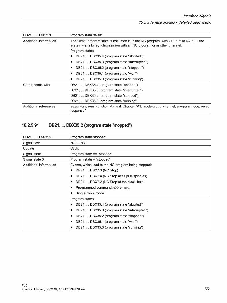
DB21, ... DBX35.1 Program state "Wait"Additional information The "Wait" program state is assumed if, in the NC program, with WAIT_M or WAIT_E the
system waits for synchronization with an NC program or another channel.Program states:● DB21, ... DBX35.4 (program state "aborted")● DB21, ... DBX35.3 (program state "interrupted")● DB21, ... DBX35.2 (program state "stopped")● DB21, ... DBX35.1 (program state "wait")● DB21, ... DBX35.0 (program state "running")
Corresponds with DB21, ... DBX35.4 (program state "aborted")DB21, ... DBX35.3 (program state "interrupted")DB21, ... DBX35.2 (program state "stopped")DB21, ... DBX35.0 (program state "running")
Additional references Basic Functions Function Manual; Chapter "K1: mode group, channel, program mode, reset response"
18.2.5.91 DB21, ... DBX35.2 (program state "stopped")
DB21, ... DBX35.2 Program state"stopped"Signal flow NC → PLCUpdate CyclicSignal state 1 Program state == "stopped"Signal state 0 Program state ≠ "stopped"Additional information Events, which lead to the NC program being stopped:
● DB21, ... DBX7.3 (NC Stop)● DB21, ... DBX7.4 (NC Stop axes plus spindles)● DB21, ... DBX7.2 (NC Stop at the block limit)● Programmed command M00 or M01● Single-block modeProgram states:● DB21, ... DBX35.4 (program state "aborted")● DB21, ... DBX35.3 (program state "interrupted")● DB21, ... DBX35.2 (program state "stopped")● DB21, ... DBX35.1 (program state "wait")● DB21, ... DBX35.0 (program state "running")
Interface signals18.2 Interface signals - detailed description
PLCFunction Manual, 06/2019, A5E47433877B AA 551

DB21, ... DBX35.2 Program state"stopped"Corresponds with DB21, ... DBX7.3 (NC Stop)
DB21, ... DBX7.4 (NC Stop axes plus spindles)DB21, ... DBX7.2 (NC Stop at the block limit)DB21, ... DBX35.4 (program state "aborted")DB21, ... DBX35.3 (program state "interrupted")DB21, ... DBX35.1 (program state "wait")DB21, ... DBX35.0 (program state "running")
Additional references Basic Functions Function Manual; Chapter "K1: mode group, channel, program mode, reset response"
18.2.5.92 DB21, ... DBX35.3 (program state "interrupted")
DB21, ... DBX35.3 Program state "interrupted"Signal flow NC → PLCUpdate CyclicSignal state 1 Program state == "interrupted"Signal state 0 Program state ≠ "interrupted"Additional information The signal indicates that the interrupted NC program can be continued with NC start (DB21, ...
DBX7.1 = 1).For example, the "interrupted" state is assumed if, in the "stopped" state (DB21, ... DBX35.2 == 1), the system changes from the AUTOMATIC or MDI mode into the JOG mode. After a subsequent operating mode change from JOG to AUTOMATIC or MDI, the NC program can be executed again from the interruption point using an NC start (DB21, ... DBX7.1 = 1).Program states:● DB21, ... DBX35.4 (program state "aborted")● DB21, ... DBX35.3 (program state "interrupted")● DB21, ... DBX35.2 (program state "stopped")● DB21, ... DBX35.1 (program state "wait")● DB21, ... DBX35.0 (program state "running")
Corresponds with DB21, ... DBX35.4 (program state "aborted")DB21, ... DBX35.2 (program state "stopped")DB21, ... DBX35.1 (program state "wait")DB21, ... DBX35.0 (program state "running")
Additional references Basic Functions Function Manual; Chapter "K1: mode group, channel, program mode, reset response"
18.2.5.93 DB21, ... DBX35.4 (program state "aborted")
DB21, ... DBX35.4 Program state "aborted"Signal flow NC → PLCUpdate CyclicSignal state 1 Program state == "aborted"
Interface signals18.2 Interface signals - detailed description
PLC552 Function Manual, 06/2019, A5E47433877B AA

DB21, ... DBX35.4 Program state "aborted"Signal state 0 Program state ≠ "aborted"Additional information The signal is set in the following cases:
● The actual NC program was selected in the channel, however it was not started.● The actual NC program was executed in the channel, and aborted using DB21, ... DBX7.7
= 1 (channel reset).Program states:● DB21, ... DBX35.4 (program state "aborted")● DB21, ... DBX35.3 (program state "interrupted")● DB21, ... DBX35.2 (program state "stopped")● DB21, ... DBX35.1 (program state "wait")● DB21, ... DBX35.0 (program state "running")
Corresponds with DB21, ... DBX7.7 (reset)DB21, ... DBX35.3 (program state "interrupted")DB21, ... DBX35.2 (program state "stopped")DB21, ... DBX35.1 (program state "wait")DB21, ... DBX35.0 (program state "running")
Additional references Basic Functions Function Manual; Chapter "K1: mode group, channel, program mode, reset response"
18.2.5.94 DB21, ... DBX35.5 (channel state "active")
DB21, ... DBX35.5 Channel state "active"Signal flow NC → PLCUpdate CyclicSignal state 1 Channel state == "active"Signal state 0 Channel state ≠ "active"Additional information The signal is set in the following cases:
● An NC program is being executed in the Automatic or MDI mode● At least one axis is being traversed in the JOG mode.Channel states:● DB21, ... DBX35.5 (channel state "active")● DB21, ... DBX35.6 (channel state "interrupted")● DB21, ... DBX35.7 (channel state "reset")
Corresponds with DB21, ... DBX35.6 (channel state "interrupted")DB21, ... DBX35.7 (channel state "reset")
Additional references Basic Functions Function Manual; Chapter "K1: mode group, channel, program mode, reset response"
Interface signals18.2 Interface signals - detailed description
PLCFunction Manual, 06/2019, A5E47433877B AA 553

18.2.5.95 DB21, ... DBX35.6 (channel state "interrupted")
DB21, ... DBX35.6 Channel state "interrupted"Signal flow NC → PLCUpdate CyclicSignal state 1 Channel state == "interrupted"Signal state 0 Channel state ≠ "interrupted"Additional information An interruption can be initiated when executing an NC program in the AUTOMATIC or MDA
mode - or in the JOG mode while an axis is traversing as a result of the following events:● DB21, ... DBX7.3 (NC Stop)● DB21, ... DBX7.4 (NC Stop axes plus spindles)● DB21, ... DBX7.2 (NC Stop at the block limit)● Programmed stop M00 or M01● Single-block modeChannel states:● DB21, ... DBX35.5 (channel state "active")● DB21, ... DBX35.6 (channel state "interrupted")● DB21, ... DBX35.7 (channel state "reset")
Corresponds with DB21, ... DBX7.3 (NC Stop)DB21, ... DBX7.4 (NC Stop axes plus spindles)DB21, ... DBX7.2 (NC Stop at the block limit)DB21, ... DBX35.5 (channel state "active")DB21, ... DBX35.7 (channel state "reset")
Additional references Basic Functions Function Manual; Chapter "K1: mode group, channel, program mode, reset response"
18.2.5.96 DB21, ... DBX35.7 (channel state "reset")
DB21, ... DBX35.7 Channel state "reset"Signal flow NC → PLCUpdate CyclicSignal state 1 Channel state == "reset"Signal state 0 Channel state ≠ "reset"Additional information The signal is set in the following cases:
● end of program reset (M02 / M30)● Channel reset● Warm restart (power on)Channel states:● DB21, ... DBX35.5 (channel state "active")● DB21, ... DBX35.6 (channel state "interrupted")● DB21, ... DBX35.7 (channel state "reset")
Interface signals18.2 Interface signals - detailed description
PLC554 Function Manual, 06/2019, A5E47433877B AA

DB21, ... DBX35.7 Channel state "reset"Corresponds with DB21, ... DBX35.5 (channel state "active")
DB21, ... DBX35.6 (channel state "interrupted")Additional references Basic Functions Function Manual; Chapter "K1: mode group, channel, program mode, reset
response"
18.2.5.97 DB21, ... DBX36.2 (all axes that have to be referenced have been referenced)
DB21, ... DBX36.2 All axes that have to be referenced are referencedSignal flow NC → PLCUpdate CyclicSignal state 1 All axes that must be referenced (linear axes and rotary axes) of the channel are referenced.
The machine data:MD20700 $MC_REFP_NC_START_LOCK (NC start inhibit without reference point)is zero.If two position measuring systems are connected to an axis, that would prevent an NC start, then the active one must be referenced so that the axis is considered to have been referenced. An NC Start command for the part program processing is only accepted when this signal is present.Axes that have to be referenced are axes, if:MD34110 $MA_REFP_CYCLE_NR _ = -1and the axis is not in the parked position (position measuring system inactive and the con‐troller enable withdrawn).
Signal state 0 One or more axes of the channel that have to be referenced are not referenced.Additional information The spindles of the channel have no effect on this interface signal.Corresponds with DB31, ... DBX60.4 (referenced / synchronized 1)
DB31, ... DBX60.5 (referenced / synchronized 2)Additional references Basic Functions Function Manual; Chapter "R1: referencing"
18.2.5.98 DB21, ... DBX36.3 (all axes stationary)
DB21, ... DBX36.3 All axes stationarySignal flow NC → PLCUpdate CyclicSignal state 1 All channel axes are stationary - and no other traversing motion is active.Signal state 0 Not all channel axes are stationary - or other traversing motion is presently active.Additional information Criterion for "axis stationary": Interpolator endAdditional references Function Manual, Basic Functions; Chapter "B1: Continuous-path mode, Exact stop, Look
Ahead" > "Exact stop mode"
Interface signals18.2 Interface signals - detailed description
PLCFunction Manual, 06/2019, A5E47433877B AA 555

18.2.5.99 DB21, ... DBX36.4 (interrupt handling active)
DB21, ... DBX36.4 Interrupt handling activeSignal flow NC → PLCUpdate CyclicSignal state 1 Interrupt handling is active.
One or more channels in the mode group are not in the desired operating mode as the result of an active interrupt routine.
Signal state 0 Interrupt handling is not active.All channels are operating in the requested mode.
Additional information NoteThe interface signal is notset, if an interrupt is handled in a program mode (AUTOMATIC or MDI).
Corresponds with MD11600 $MN_BAG_MASK (definition of the mode group response)Additional references Basic Functions Function Manual; Chapter "K1: mode group, channel, program mode, reset
response"
18.2.5.100 DB21, ... DBX36.5 (channel ready)
DB21, ... DBX36.5 Channel is readySignal flow NC → PLCUpdate CyclicSignal state 1 The channel is readySignal state 0 The channel is not ready.Additional information The channel is ready to execute an NC program and to traverse axes and spindle that are
assigned to the channel.Corresponds with MD11600 $MN_BAG_MASK (definition of the mode group response)Additional references Basic Functions Function Manual; Chapter "K1: mode group, channel, program mode, reset
response"
18.2.5.101 DB21, ... DBX36.6 (channel-specific NC alarm active)
DB21, ... DBX36.6 Channel-specific NC alarm active Signal flow NC → PLCUpdate CyclicSignal state 1 At least one NC alarm is active in the channel.Signal state 0 No NC alarm is active in the channel.Corresponds with DB21, ... DBX36.7 (NC alarm with machining stop active)
DB10 DBX109.0 (NC alarm active)Additional references Diagnostics guide
Interface signals18.2 Interface signals - detailed description
PLC556 Function Manual, 06/2019, A5E47433877B AA

18.2.5.102 DB21, ... DBX36.7 (NC alarm with machining stop active)
DB21, ... DBX36.7 NC alarm with machining stop is active Signal flow NC → PLCUpdate CyclicSignal state 1 At least one NC alarm with machining stop is active in the channel.Signal state 0 No NC alarm with machining stop is active in the channel.Corresponds with DB21, ... DBX36.6 (channel-specific NC alarm active)
DB10 DBX109.0 (NC alarm active)Additional references Diagnostics guide
18.2.5.103 DB21, ... DBX37.0 - 2 (contour handwheel active)
DB21, ... DBX37.0 - 2 Contour handwheel activeSignal flow PLC → NCUpdate CyclicAdditional information The interface can be interpreted either bit or binary-coded. The definition is realized using
machine data MD11324.Bit coded: maximum 3 handwheels Bit 2 Bit 1 Bit 0 Number of the assigned handwheel
0 0 0 No handwheel assignment0 0 1 10 1 0 21 0 0 3
Binary coded: maximum 6 handwheels Bit 2 Bit 1 Bit 0 Number of the assigned handwheel
0 0 0 No handwheel assignment0 0 1 10 1 0 20 1 1 31 0 0 41 0 1 51 1 0 6
NoteAt any one time, an axis can only be assigned to one handwheel. If, for bit coding, several interface signals are set simultaneously, then the following priority applies: "Handwheel 1" before "Handwheel 2" before "Handwheel 3".
Corresponds with DB21 ... DBX30.0 - 2 (activate contour handwheel)MD11324 $MN_HANDWH_VDI_REPRESENTATION (representation of the handwheel num‐ber at the VDI interface)
Additional references Function Manual, Extended Functions; Chapter "H1: manual and handwheel travel"
Interface signals18.2 Interface signals - detailed description
PLCFunction Manual, 06/2019, A5E47433877B AA 557

18.2.5.104 DB21, ... DBX37.3 (clearance control (CLC): Active)
DB21, ... DBX37.3 Clearance control (CLC):Signal flow NC → PLCUpdate CyclicSignal state 1 Clearance control (CLC) is active.Signal state 0 Clearance control (CLC) is not active.Corresponds with DB21, ... DBX1.4 (clearance control (CLC): stop)
DB21, ... DBX1.5 (clearance control (CLC): Override)DB21, ... DBX37.4 (clearance control (CLC): Stop at the lower motion limit)DB21, ... DBX37.5 (clearance control (CLC): Stop at the upper motion limit)DB21, ... DBX37.4 - 5 (clearance control (CLC): Motion has stopped)
Additional references Function Manual, Special Functions; Chapter "TE1: Clearance control"
18.2.5.105 DB21, ... DBX37.4 (clearance control (CLC): Stop at the lower motion limit)
DB21, ... DBX37.4 Clearance control (CLC): Stop at the lower motion limitSignal flow NC → PLCUpdate CyclicSignal state 1 The traversing motion of the clearance-controlled axis, generated by the clearance control,
has reached the lower motion limit and was stopped.Signal state 0 The traversing motion of the clearance-controlled axis, generated by the clearance control,
has not reached the lower motion limit.Additional information The lower motion limit of the clearance control is set in machine data:
MD62505 $MC_CLC_SENSOR_LOWER_LIMITThe parameterized limit value can be adapted on a block-specific basis by programming CLC_LIM(...) in the part program.NoteIf, in addition to DB21, ... DBX37.4, DB21, ... DBX37.5 are also simultaneously set, then signal "DB21, ... DBX37.3 (clearance control (CLC): Active) (Page 558)"is active.
Corresponds with CLC_LIM(...) ; the control range is limitedDB21, ... DBX37.5 (clearance control (CLC): Stop at the upper motion limit)DB21, ... DBX37.4 - 5 (clearance control (CLC): Motion has stopped)MD62505 $MC_CLC_SENSOR_LOWER_LIMIT (lower clearance control motion limit)
Additional references Function Manual, Special Functions; Chapter "TE1: Clearance control"
18.2.5.106 DB21, ... DBX37.5 (clearance control (CLC): Stop at the upper motion limit)
DB21, ... DBX37.5 Clearance control (CLC): Stop at the upper motion limitSignal flow NC → PLCUpdate CyclicSignal state 1 The traversing motion of the clearance-controlled axis, generated by the clearance control,
has reached the upper motion limit and was stopped.
Interface signals18.2 Interface signals - detailed description
PLC558 Function Manual, 06/2019, A5E47433877B AA

DB21, ... DBX37.5 Clearance control (CLC): Stop at the upper motion limitSignal state 0 The traversing motion of the clearance-controlled axis, generated by the clearance control,
has not reached the upper motion limit.Additional information The upper motion limit of the clearance control is set in machine data:
MD62506 $MC_CLC_SENSOR_UPPER_LIMITThe parameterized limit value can be adapted on a block-specific basis by programming CLC_LIM(...) in the part program.NoteIf, in addition to DB21, ... DBX37.5, DB21, ... DBX37.4 are also simultaneously set, then signal "DB21, ... DBX37.3 (clearance control (CLC): Active) (Page 558)"is active.
Corresponds with CLC_LIM(...) ; the control range is limitedDB21, ... DBX37.4 (clearance control (CLC): Stop at the lower motion limit)DB21, ... DBX37.4 - 5 (clearance control (CLC): Motion has stopped)MD62506 $MC_CLC_SENSOR_UPPER_LIMIT (upper clearance control motion limit)
Additional references Function Manual, Special Functions; Chapter "TE1: Clearance control"
18.2.5.107 DB21, ... DBX37.6 (read-in disable is ignored)
DB21, ... DBX37.6 Read-in disable is ignoredSignal flow NC → PLCUpdate CyclicSignal state 1 Read-in disable (DB21, ... DBX6.1) is ignored.Signal state 0 Read-in disable (DB21, ... DBX6.1) is not ignored.Additional information Read-in disable (DB21, ... DBX6.1) is ignored, if the following applies:
DB21, ... DBX6.1 == 1 (read-in disable) AND actual block has the status "read-in disable inactive"Read-in disable (DB21, ... DBX6.1) is not ignored, if the following applies:DB21, ... DBX6.1 == 0 (read-in disable) OR ( DB21, ... DBX6.1 == 1 (read-in disable) AND actual block has the status "read-in disable active" )Blocks for which read-in disable is ignored have the status "read-in disable inactive".The following machine data is used to specify that the read-in disable (DB21, ... DBX6.1) is to be ignored:● MD11602 $MN_ASUP_START_MASK, bit 2● MD20116 $MC_IGNORE_INHIBIT_ASUP● MD20107 $MC_ PROG_EVENT_IGN_INHIBIT
Corresponds with DB21, ... DBX37.7 (stop at block end is ignored during single block (SBL))MD11602 $MN_ASUP_START_MASK, bit 2 (start also permitted if read-in disable is active)MD20116 $MC_IGNORE_INHIBIT_ASUP (execute interrupt program in spite of read-in dis‐able)MD20107 $MC_ PROG_EVENT_IGN_INHIBIT (prog events ignore read-in disable)
Additional references Basic Functions Function Manual; Chapter "K1: mode group, channel, program mode, reset response"
Interface signals18.2 Interface signals - detailed description
PLCFunction Manual, 06/2019, A5E47433877B AA 559

18.2.5.108 DB21, ... DBX37.7 (stop at block end is ignored during single block (SBL))
DB21, ... DBX37.7 Stop at block end is ignored during single block (SBL)Signal flow NC → PLCUpdate CyclicSignal state 1 Stop at block end is ignored during single block (SBL).Signal state 0 Stop at block end is not ignored during single block (SBL).Additional information Stop at block end is ignored during single block (SBL), if the following applies:
DB21, ... DBX0.4 == 1 (single block) AND actual block has the status "single block inactive"Stop at block end is not ignored during single block (SBL), if the following applies:DB21, ... DBB0.4 == 0 (single block) OR (DB21, ... DBB0.4 == 1 (single block) AND actual block has the status "single block active")The following machine data and commands are used to specify that the stop at block end during single block (DB21, ... DBX0.4) is to be ignored:● MD10702 $MN_IGNORE_SINGLEBLOCK_MASK (prevent single-block stop)● MD20117 $MC_IGNORE_SINGLEBLOCK_ASUP (execute interrupt program completely
in spite of single block)● MD20106 $MC_PROG_EVENT_IGN_SINGLEBLOCK (prog events ignore single block)● SBLOF (suppress single block), SBLON (neutral single block suppression)Blocks for which stop at block end during single block is ignored are designated as "single block inactive".
Corresponds with DB21, ... DBX0.4 (single block)DB21, ... DBX37.6 (read-in disable is ignored)
Additional references Basic Functions Function Manual; Chapter "K1: mode group, channel, program mode, reset response"
18.2.5.109 DB21, ... DBX38.0 (stroke initiation active)
DB21, ... DBX38.0 Stroke initiation activeSignal flow NC → PLCSignal state 1 Stroke initiation is active.Signal state 0 Stroke initiation is not active.Corresponds with DB21, ... DBX3.0 (stroke enable)Additional references Function Manual, Extended Functions; Chapter "N4: Punching and nibbling"
18.2.5.110 DB21, ... DBX38.1 (manual stroke initiation: Acknowledgment)
DB21, ... DBX38.1 Manual stroke initiation: AcknowledgmentSignal flow NC → PLCSignal state 1 Manual stroke has been initiated.Signal state 0 Manual stroke was not initiated.
Interface signals18.2 Interface signals - detailed description
PLC560 Function Manual, 06/2019, A5E47433877B AA

DB21, ... DBX38.1 Manual stroke initiation: AcknowledgmentCorresponds with DB21, ... DBX3.0 (stroke enable)
DB21, ... DBX3.1 (manual stroke initiation)DB21, ... DBX3.5 (manual stroke initiation 2)DB21, ... DBX38.0 (stroke initiation active)
Additional references Function Manual, Extended Functions; Chapter "N4: Punching and nibbling"
18.2.5.111 DB21, ... DBX39.1 (NC alarm with program stop)
DB21, ... DBX39.1 NC alarm with program stopSignal flow NC → PLCUpdate CyclicSignal state 1 The interface signal indicates when the program progress is blocked by the presence of an
alarm. This relates to all alarms generated by stop response:● Stop on the path with deletion of the ready signal ● Axes are braked● Immediate stop on the path● Interpreter is stopped, IPO buffer is still being executed.● No stop at end of blockAlarms with the following alarm response are also taken into account: ● NC start disable in this channel● NC start disable in this channel, ASUB starts, where relevant, are permittedFor alarms with this response the interface signal is not set until an NC start has been trig‐gered and only if the alarm has not yet been acknowledged. In this case, the interface signal is not set until NC start.The interface signals are set if the start of an ASUB is refused because of an NC start disable in this channel. The interface signal is deleted as soon as alarm responses that activated the signal are no longer active. This depends on the delete conditions of the alarms.
Signal state 0 No NC alarm with program stop is present in the channel.Corresponds with DB10 DBX109.0 (NC alarm present)
DB21, ... DBX36.6 (channel-specific NC alarm present)DB21, ... DBX36.7 (NC alarm with machining stop present)
Additional references Diagnostics Manual
18.2.5.112 DB21, ... DBX39.5 (Contour handwheel: handwheel direction of rotation inversion active)
DB21, ... DBX39.5 Contour handwheel: handwheel direction of rotation inversion activeSignal flow NC → PLCUpdate CyclicSignal state 1 Inversion of the direction of rotation of the contour handwheel is active.Signal state 0 Inversion of the direction of rotation of the contour handwheel is not active.
Interface signals18.2 Interface signals - detailed description
PLCFunction Manual, 06/2019, A5E47433877B AA 561

DB21, ... DBX39.5 Contour handwheel: handwheel direction of rotation inversion activeCorresponds with DB31, ... DBX31.5 (contour handwheel: invert handwheel direction of rotation)Additional references Function Manual, Extended Functions; Chapter "H1: manual and handwheel travel"
18.2.5.113 DB21, ... DBX40.0 - 2 (geometry axis 1: handwheel active)
DB21, ... DBX40.0 - 2 Geometry axis 1: handwheel activeSignal flow NC → PLCUpdate CyclicAdditional information The interface can be interpreted either bit or binary-coded. The definition is realized using
machine data MD11324.Bit coded: maximum 3 handwheels Bit 2 Bit 1 Bit 0 Number of the assigned handwheel
0 0 0 No handwheel assignment0 0 1 10 1 0 21 0 0 3
Binary coded: maximum 6 handwheels Bit 2 Bit 1 Bit 0 Number of the assigned handwheel
0 0 0 No handwheel assignment0 0 1 10 1 0 20 1 1 31 0 0 41 0 1 51 1 0 6
NoteAt any one time, an axis can only be assigned to one handwheel. If, for bit coding, several interface signals are set simultaneously, then the following priority applies: "Handwheel 1" before "Handwheel 2" before "Handwheel 3".
Corresponds with DB21, ... DBX46.0 - 2 (geometry axis 2: handwheel active)DB21, ... DBX52.0 - 2 (geometry axis 3: handwheel active)DB21, ... DBX12.0 - 2 (geometry axis 1: activate handwheel)DB21, ... DBX16.0 - 2 (geometry axis 2: activate handwheel)DB21, ... DBX20.0 - 2 (geometry axis 3: activate handwheel)MD11324 $MN_HANDWH_VDI_REPRESENTATION (representation of the handwheel num‐ber at the VDI interface)
Additional references Function Manual, Extended Functions; Chapter "H1: manual and handwheel travel"
Interface signals18.2 Interface signals - detailed description
PLC562 Function Manual, 06/2019, A5E47433877B AA

18.2.5.114 DB21, ... DBX40.4 - 5 (geometry axis 1: traversing request "Plus" / "Minus")
DB21, ... DBX40.4 - 5 Geometry axis 1: traversing request "Plus" / "Minus"Signal flow NC → PLCUpdate CyclicSignal state 1 There is a traversing request available for the geometry axis.Signal state 0 There is no traversing request available for the geometry axis.Additional information Depending on the mode selected, the traversing request is initiated in different ways:
● JOG mode"Plus" or "Minus" traversing key
● REF modeTraversing key that initiates traversing motion in the direction of the reference point.
● AUTOMATIC or MDI modeA program block with a traversing operation is executed for a geometry axis.
There is a signal for each axis direction:Bit 4 Traversing request "Minus" (for traversing in the negative axis direction)Bit 5 Traversing key "Plus" (for traversing in the positive axis direction)
Corresponds with DB21, ... DBX46.4 - 5 (geometry axis 2: traversing request "Plus" / "Minus")DB21, ... DBX52.4 - 5 (geometry axis 3: traversing request "Plus" / "Minus")DB21, ... DBX12.6 - 7 (geometry axis 1: traversing keys "Plus" / "Minus")DB21, ... DBX16.6 - 7 (geometry axis 2: traversing keys "Plus" / "Minus")DB21, ... DBX20.6 - 7 (geometry axis 3: traversing keys "Plus" / "Minus")DB21, ... DBX40.6 - 7 (geometry axis 1: traversing command "Plus" / "Minus")DB21, ... DBX46.6 - 7 (geometry axis 2: traversing command "Plus" / "Minus")DB21, ... DBX52.6 - 7 (geometry axis 3: traversing command "Plus" / "Minus")
Additional references Function Manual, Extended Functions; Chapter "H1: manual and handwheel travel"
18.2.5.115 DB21, ... DBX40.6 - 7 (geometry axis 1: traversing command "Plus" / "Minus")
DB21, ... DBX40.6 - 7 Geometry axis 1: traversing command "Plus" / "Minus"Signal flow NC → PLCUpdate CyclicSignal state 1 There is a traversing request for the geometry axis or the geometry axis is traversing.Signal state 0 There is not a traversing request for the geometry axis or the geometry axis is not traversing.Additional information Depending on the setting of MD17900, bit 0, the traversing command is already output if a
"Traversing request" is active (bit 0 = 0) or only if the axis is actually traversing (bit 0 = 1).There is a signal for each axis direction:
Bit 6 Traversing command "Minus" (for traversing in the negative axis direction)Bit 7 Traversing command "Plus" (for traversing in the positive axis direction)
Application exampleReleasing the axis clamp when the traversing command is identified.NoteFor axes where clamping is not released until a drive command is detected, the continuous-path mode (G64) is not possible.
Interface signals18.2 Interface signals - detailed description
PLCFunction Manual, 06/2019, A5E47433877B AA 563
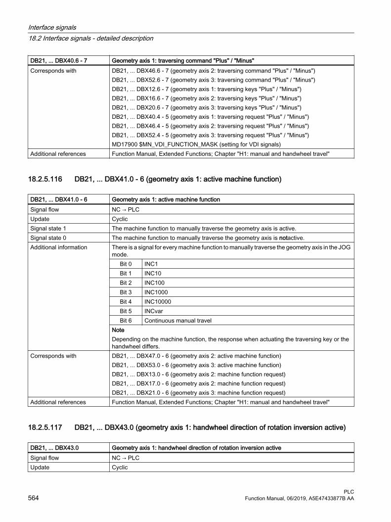
DB21, ... DBX40.6 - 7 Geometry axis 1: traversing command "Plus" / "Minus"Corresponds with DB21, ... DBX46.6 - 7 (geometry axis 2: traversing command "Plus" / "Minus")
DB21, ... DBX52.6 - 7 (geometry axis 3: traversing command "Plus" / "Minus")DB21, ... DBX12.6 - 7 (geometry axis 1: traversing keys "Plus" / "Minus")DB21, ... DBX16.6 - 7 (geometry axis 2: traversing keys "Plus" / "Minus")DB21, ... DBX20.6 - 7 (geometry axis 3: traversing keys "Plus" / "Minus")DB21, ... DBX40.4 - 5 (geometry axis 1: traversing request "Plus" / "Minus")DB21, ... DBX46.4 - 5 (geometry axis 2: traversing request "Plus" / "Minus")DB21, ... DBX52.4 - 5 (geometry axis 3: traversing request "Plus" / "Minus")MD17900 $MN_VDI_FUNCTION_MASK (setting for VDI signals)
Additional references Function Manual, Extended Functions; Chapter "H1: manual and handwheel travel"
18.2.5.116 DB21, ... DBX41.0 - 6 (geometry axis 1: active machine function)
DB21, ... DBX41.0 - 6 Geometry axis 1: active machine functionSignal flow NC → PLCUpdate CyclicSignal state 1 The machine function to manually traverse the geometry axis is active.Signal state 0 The machine function to manually traverse the geometry axis is notactive.Additional information There is a signal for every machine function to manually traverse the geometry axis in the JOG
mode.Bit 0 INC1Bit 1 INC10Bit 2 INC100Bit 3 INC1000Bit 4 INC10000Bit 5 INCvarBit 6 Continuous manual travel
NoteDepending on the machine function, the response when actuating the traversing key or the handwheel differs.
Corresponds with DB21, ... DBX47.0 - 6 (geometry axis 2: active machine function)DB21, ... DBX53.0 - 6 (geometry axis 3: active machine function)DB21, ... DBX13.0 - 6 (geometry axis 2: machine function request)DB21, ... DBX17.0 - 6 (geometry axis 2: machine function request)DB21, ... DBX21.0 - 6 (geometry axis 3: machine function request)
Additional references Function Manual, Extended Functions; Chapter "H1: manual and handwheel travel"
18.2.5.117 DB21, ... DBX43.0 (geometry axis 1: handwheel direction of rotation inversion active)
DB21, ... DBX43.0 Geometry axis 1: handwheel direction of rotation inversion activeSignal flow NC → PLCUpdate Cyclic
Interface signals18.2 Interface signals - detailed description
PLC564 Function Manual, 06/2019, A5E47433877B AA
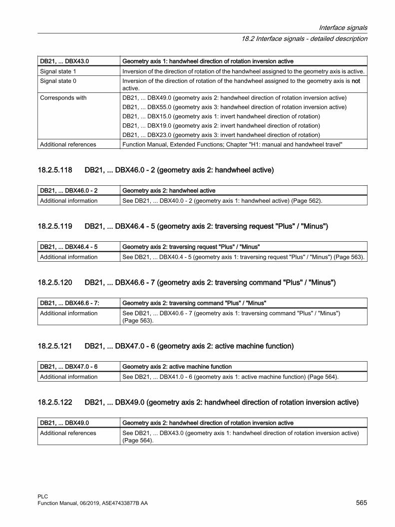
DB21, ... DBX43.0 Geometry axis 1: handwheel direction of rotation inversion activeSignal state 1 Inversion of the direction of rotation of the handwheel assigned to the geometry axis is active.Signal state 0 Inversion of the direction of rotation of the handwheel assigned to the geometry axis is not
active.Corresponds with DB21, ... DBX49.0 (geometry axis 2: handwheel direction of rotation inversion active)
DB21, ... DBX55.0 (geometry axis 3: handwheel direction of rotation inversion active)DB21, ... DBX15.0 (geometry axis 1: invert handwheel direction of rotation)DB21, ... DBX19.0 (geometry axis 2: invert handwheel direction of rotation)DB21, ... DBX23.0 (geometry axis 3: invert handwheel direction of rotation)
Additional references Function Manual, Extended Functions; Chapter "H1: manual and handwheel travel"
18.2.5.118 DB21, ... DBX46.0 - 2 (geometry axis 2: handwheel active)
DB21, ... DBX46.0 - 2 Geometry axis 2: handwheel activeAdditional information See DB21, ... DBX40.0 - 2 (geometry axis 1: handwheel active) (Page 562).
18.2.5.119 DB21, ... DBX46.4 - 5 (geometry axis 2: traversing request "Plus" / "Minus")
DB21, ... DBX46.4 - 5 Geometry axis 2: traversing request "Plus" / "Minus"Additional information See DB21, ... DBX40.4 - 5 (geometry axis 1: traversing request "Plus" / "Minus") (Page 563).
18.2.5.120 DB21, ... DBX46.6 - 7 (geometry axis 2: traversing command "Plus" / "Minus")
DB21, ... DBX46.6 - 7: Geometry axis 2: traversing command "Plus" / "Minus"Additional information See DB21, ... DBX40.6 - 7 (geometry axis 1: traversing command "Plus" / "Minus")
(Page 563).
18.2.5.121 DB21, ... DBX47.0 - 6 (geometry axis 2: active machine function)
DB21, ... DBX47.0 - 6 Geometry axis 2: active machine functionAdditional information See DB21, ... DBX41.0 - 6 (geometry axis 1: active machine function) (Page 564).
18.2.5.122 DB21, ... DBX49.0 (geometry axis 2: handwheel direction of rotation inversion active)
DB21, ... DBX49.0 Geometry axis 2: handwheel direction of rotation inversion activeAdditional references See DB21, ... DBX43.0 (geometry axis 1: handwheel direction of rotation inversion active)
(Page 564).
Interface signals18.2 Interface signals - detailed description
PLCFunction Manual, 06/2019, A5E47433877B AA 565

18.2.5.123 DB21, ... DBX52.0 - 2 (geometry axis 3: handwheel active)
DB21, ... DBX52.0 - 2 Geometry axis 3: handwheel activeAdditional information See DB21, ... DBX40.0 - 2 (geometry axis 1: handwheel active) (Page 562).
18.2.5.124 DB21, ... DBX52.4 - 5 (geometry axis 3: traversing request "Plus" / "Minus")
DB21, ... DBX52.4 - 5 Geometry axis 3: traversing request "Plus" / "Minus"Additional information See DB21, ... DBX40.4 - 5 (geometry axis 1: traversing request "Plus" / "Minus") (Page 563).
18.2.5.125 DB21, ... DBX52.6 - 7 (geometry axis 3: traversing command "Plus" / "Minus")
DB21, ... DBX52.6 - 7 Geometry axis 3: traversing command "Plus" / "Minus"Additional information See DB21, ... DBX40.6 - 7 (geometry axis 1: traversing command "Plus" / "Minus")
(Page 563).
18.2.5.126 DB21, ... DBX53.0 - 6 (geometry axis 3: active machine function)
DB21, ... DBX53.0 - 6 Geometry axis 3: active machine functionAdditional information See DB21, ... DBX41.0 - 6 (geometry axis 1: active machine function) (Page 564).
18.2.5.127 DB21, ... DBX55.0 (geometry axis 3: handwheel direction of rotation inversion active)
DB21, ... DBX55.0 Geometry axis 3: handwheel direction of rotation inversion activeAdditional references See DB21, ... DBX43.0 (geometry axis 1: handwheel direction of rotation inversion active)
(Page 564).
18.2.5.128 DB21, ... DBB58, DBB60 - 65 (M-, S-, T-, D-, H-, F fct. change)
DB21, ... DBB58, DB21, ... DBB60 - 65
M, S, T, D, H, F fct. change
Signal flow NC → PLCUpdate Job-controlledSignal state 1 M, S, T, or F information was output to the interface with a new value together with the
associated change signal at the beginning of an OB1 cycle. In this case, the change signal indicates that the appropriate value is valid.
Signal state 0 The change signals are reset by the PLC basic program at the start of the next OB1 cycle. The value of the respective data is not valid.
Additional references Function Manual, Basic Functions; Chapter "H2: Auxiliary function outputs to PLC"
Interface signals18.2 Interface signals - detailed description
PLC566 Function Manual, 06/2019, A5E47433877B AA

18.2.5.129 DB21, ... DBX59.0 - 4 (M fct. 1-5 not decoded)
DB21, ... DBX59.0 - 4 M fct. 1-5 not decoded Signal flow NC → PLCUpdate Job-controlledSignal state 1 M function is greater than 99 (for extended address = 0) or for extended address > 0, not
included in the decoding list.This signal is available - together with the associated M change signal - for one OB1 cycle.Cause:● Incorrect M function programmed● M function not configured in the decoding list of the PLCRemedy e.g.:● PLC sets read-in inhibit● Output of a PLC alarm
Signal state 0 M function less than 99 (for extended address = 0) or for extended address > 0 included in the decoding list.
18.2.5.130 DB21, ... DBB60 - 64, ... DBB66 - 67 (M-, S-, T-, D-, H-, F fct. Additional quick information (quick acknowledgment)
DB21, ... DBB60 - 64, DB21, ... DBB66 - 67
M, S, T, D, H, F fct. Additional quick information (fast acknowledgment)
Signal flow NC → PLCUpdate Job-controlledSignal state 1 M, S, T, D, H or F information has been output to the interface with a new value together with
the associated change signal at the beginning of an OB1 cycle. In this case, the additional info "Quick" indicates the quick help function.
Signal state 0 The change signals are reset by the PLC basic program at the start of the next OB1 cycle. The value of the respective data is not valid.
18.2.5.131 DB21, ... DBB68 - 97 (M function 1 - 5 and extended address M function 1 - 5 )
DB21, ... DBB68 - 97 M function 1 - 5 and extended address M function 1 - 5 Signal flow NC → PLCUpdate Job-controlledAdditional information If an M function change signal (DB21, ... DBB58) is present, then the up to five M functions -
that can be programmed in an NC block - together with the number of the M function and the extended address are available here.The M function values remain until they are overwritten by new M functions.The M function values are deleted by the following events: ● The PLC powers up (boots).● A new M function is entered.
Interface signals18.2 Interface signals - detailed description
PLCFunction Manual, 06/2019, A5E47433877B AA 567

DB21, ... DBB68 - 97 M function 1 - 5 and extended address M function 1 - 5 Corresponds with DB21, ... DBX58.0 - 4 (changes signals: M function)
MD10715 $MN_M_NO_FCT_CYCLEMD10716 $MN_M_NO_FCT_CYCLE_NAMEMD10718 $MN_M_NO_FCT_CYCLE_PAR$C_M (system variable)
Additional references Function Manual, Basic Functions; Chapter "H2: Auxiliary function outputs to PLC"
18.2.5.132 DB21, ... DBB98 - 115 (S function 1 - 3 and extended address S function 1 - 3 )
DB21, ... DBB98 - 115 S function 1 - 3 and extended address S function 1 - 3 Signal flow NC → PLCUpdate Job-controlledAdditional information If an S function change signal (DB21, ... DBB60) is present, then the up to three S functions
- that can be programmed in an NC block - together with the number of the S function and the extended address are available here.The S function values remain until they are overwritten by new S functions.The S function values are deleted by the following events: ● The PLC powers up (boots).● A new S function is entered.
Corresponds with DB21, ... DBX60.0 - 2 (change signals: S function)Additional references Function Manual, Basic Functions; Chapter "H2: Auxiliary function outputs to PLC"
18.2.5.133 DB21, ... DBB118 (T function 1)
DB21, ... DBW118 or DBD118
T function 1
Signal flow NC → PLCUpdate Job-controlledAdditional information If a T function change signal (DB21, ... DBB61) is present, then number of the T functions,
programmed in the NC block, is made available here.The T function values remain until they are overwritten by new T functions.The T function values are deleted by the following events: ● The PLC powers up (boots).● A new T function is entered.
Corresponds with MD10717 $MN_T_NO_FCT_CYCLE_NAME (name of the tool change cycle for T function replacement)MD10719 $MN_T_NO_FCT_CYCLE_MODE (parameterization of the T function replace‐ment)MD22220 $MC_AUXFU_T_SYNC_TYPE (output time of the T functions)MD22550 $MC_TOOL_CHANGE_MODE (new tool compensation for M function)$C_T... (system variable)
Additional references Function Manual, Basic Functions; Chapter "H2: Auxiliary function outputs to PLC"
Interface signals18.2 Interface signals - detailed description
PLC568 Function Manual, 06/2019, A5E47433877B AA

18.2.5.134 DB21, ... DBB129 (D function 1)
DB21, ... DBB129 D function 1Signal flow NC → PLCUpdate Job-controlledAdditional information If a D function change signal (DB21, ... DBB62) is present, then the number of the D functions,
programmed in the NC block, is made available.The D function values remain until they are overwritten by new D functions.The D function values are deleted by the following events: ● The PLC powers up (boots).● A new D function is entered.
Corresponds with MD22250 $MC_AUXFU_D_SYNC_TYPE (output time D functions)MD22252 $MC_AUXFU_DL_SYNC_TYPE (output time DL functions)
Additional references Function Manual, Basic Functions; Chapter "H2: Auxiliary function outputs to PLC"
18.2.5.135 DB21, ... DBB140 - 157 (H function 1 - 3 and extended address H function 1 - 3 )
DB21, ... DBB140 - 157 H function 1 - 3 and extended address H function 1-3Signal flow NC → PLCUpdate Job-controlledAdditional information If an H function change signal (DB21, ... DBB64) is present, then the up to three H functions
- that can be programmed in an NC block - together with the number of the H function and the extended address are available here.The H function values remain until they are overwritten by new H functions.The H function values are deleted by the following events: ● The PLC powers up (boots).● A new H function is entered.
Corresponds with DB21, ... DBX64.0 - 2 (change signals: H function)MD22110 $MC_AUXFU_H_TYPE_INT (type of H-auxiliary function is an integer)MD22230 $MC_AUXFU_H_SYNC_TYPE (output time of the H functions)
Additional references Function Manual, Basic Functions; Chapter "H2: Auxiliary function outputs to PLC"
18.2.5.136 DB21, ... DBB158 - 193 (F function 1 - 6 and extended address F function 1 - 6 )
DB21, ... DBB158 - 193 F function 1 - 6 and extended address F function 1 - 6 Signal flow NC → PLCUpdate Job-controlled
Interface signals18.2 Interface signals - detailed description
PLCFunction Manual, 06/2019, A5E47433877B AA 569

DB21, ... DBB158 - 193 F function 1 - 6 and extended address F function 1 - 6 Additional information If an F function change signal (DB21, ... DBB65) is present, then the up to six F functions - that
can be programmed in an NC block - together with the number of the F function and the extended address are available here.The extended address of the F function is generated from the feedrate type (path feed or axis-specific feed) and the axis names.● Path feedrate 0● Axis-specific feedrate: Machine axis number of positioning axis 1, 2, 3, ... maximum
number of machine axesThe F function values remain until they are overwritten by new F functions.The F function values are deleted by the following events: ● The PLC powers up (boots).● A new F function is entered.
Corresponds with MD22240 $MC_AUXFU_F_SYNC_TYPE (output time of F functions)Additional references Function Manual, Basic Functions; Chapter "H2: Auxiliary function outputs to PLC"
18.2.5.137 DB21, ... DBB194 - 206 (dynamic M functions: M0 - M99)
DB21, ... DBX194.0 - 7 - DBX206.0 - 3
Dynamic M functions M0 - M99
Signal flow NC → PLCUpdate Job-controlledSignal state 1 The associated M function was has been decoded.Signal state 0 The associated M function has not been decoded or the interface signal has been reset from
the PLC basic program as acknowledgment.For a general auxiliary function output, the interface signal is reset by the PLC basic program after OB1 has been completely executed.For a fast auxiliary function output, the interface signal is reset by the PLC basic program in the same OB40 cycle.
Additional references Function Manual, Basic Functions; Chapter "H2: Auxiliary function outputs to PLC"
18.2.5.138 DB21, ... DBB208 - 271 (active G command of group 1 to 60)
DB21, ... DBB208 - 271 Active G command of group 1 to 60Signal flow NC → PLCUpdate Cyclic
Interface signals18.2 Interface signals - detailed description
PLC570 Function Manual, 06/2019, A5E47433877B AA

DB21, ... DBB208 - 271 Active G command of group 1 to 60Additional information The G command displayed in the BCD format or its mnemonic identifier is active in the speci‐
fied G group.DBB Meaning208 G group 1: Internal number of the active G command209 G group 2: Internal number of the active G command... ...
271 G group 64: Internal number of the active G commandApplication exampleG group 14 ≙ DBB208 + 14 - 1 = DBB221, Active G commands: DBB221 == 1 ≙ internal number for G commandG90
Bit 7 6 5 4 3 2 1 0Value 128 64 32 16 8 4 2 1
DBB221 0 0 0 0 0 0 0 1Special caseFor a value of 0, no G command or mnemonic identifier of the G group is active.NoteIn contrast to auxiliary functions, G commands are not output to the PLC subject to acknowl‐edgment, i.e. processing of the part program is continued immediately after the G command output.
Additional references Basic Functions Function Manual; Chapter "K1: mode group, channel, program mode, reset response"A complete list of the G groups, G commands and their internal numbers can be found in: Programming Manual, Fundamentals; Chapter "Tables" > "G commands"
18.2.5.139 DB21, ... DBX272.0 - 273.1 (machine-related protection zone 1 - 10 preactivated)
DB21, ... DBX272.0 - 273.1 Machine-related protection zone 1 - 10 preactivatedSignal flow NC → PLCUpdate CyclicSignal state 1 The machine-related protection zone 1 (...10) is preactivated.
Preactivation is realized in the NC program using command NPROT.Signal state 0 The machine-related protection zone 1 (...10) is not preactivated. Additional information Note
Only a preactivated machine-related protection zone can be activated or deactivated using the corresponding interface signal:DB21, ... DBX8.0 - 9.1 (activate machine-related protection zone 1 - 10)
Corresponds with DB21, ... DBX1.1 (enable protection zones)DB21, ... DBX8.0 - 9.1 (activate machine-related protection zone 1 - 10)DB21, ... DBX10.0 - 11.1 (activate channel-specific protection zone 1 - 10)DB21, ... DBX274.0 – 275.1 (channel-specific protection zone 1 - 10 preactivated)DB21, ... DBX276.0 - 277.1 (machine-related protection zone 1 - 10 violated)DB21, ... DBX278.0 – 279.1 (channel-specific protection zone 1 - 10 violated)
Additional references Basic Functions Function Manual; Chapter "A5: Protection zones"
Interface signals18.2 Interface signals - detailed description
PLCFunction Manual, 06/2019, A5E47433877B AA 571

18.2.5.140 DB21, ... DBX274.0 – 275.1 (channel-specific protection zone 1 - 10 preactivated)
DB21, ... DBX274.0 - 275.1 Channel-related protection zone 1 - 10 preactivatedSignal flow NC → PLCUpdate CyclicSignal state 1 The channel-specific protection zone 1 (...10) is preactivated.
Preactivation is realized in the NC program using command NPROT.Signal state 0 The channel-specific protection zone 1 (...10) is not preactivated. Additional information Note
Only a preactivated channel-specific protection zone can be activated or deactivated using the corresponding interface signal:DB21, ... DBX10.0 - 11.1 (activate channel-specific protection zone 1 - 10)
Corresponds with DB21, ... DBX1.1 (enable protection zones)DB21, ... DBX8.0 - 9.1 (activate machine-related protection zone 1 - 10)DB21, ... DBX10.0 - 11.1 (activate channel-specific protection zone 1 - 10)DB21, ... DBX272.0 - 273.1 (machine-related protection zone 1 - 10 preactivated)DB21, ... DBX276.0 - 277.1 (machine-related protection zone 1 - 10 violated)DB21, ... DBX278.0 – 279.1 (channel-specific protection zone 1 - 10 violated)
Additional references Basic Functions Function Manual; Chapter "A5: Protection zones"
18.2.5.141 DB21, ... DBX276.0 - 277.1 (machine-related protection zone 1 - 10 violated)
DB21, ... DBX276.0 - 277.1 Machine-related protection zone 1 - 10 violatedSignal flow NC → PLCUpdate CyclicSignal state 1 The activated, machine-related protection zone 1 - 10 wasviolated in the current block or in the
current JOG traversing motion.The preactivated, machine-related protection zone 1 - 10 would be violated in the current block if it would be active.
Signal state 0 The activated, machine-related protection zone 1 - 10 was not violated in the current block or in the current JOG traversing motion.The preactivated, machine-related protection zone 1 - 10 would not be violated in the current block if it would be active.
Corresponds with DB21, ... DBX1.1 (enable protection zones)DB21, ... DBX8.0 - 9.1 (activate machine-related protection zone 1 - 10)DB21, ... DBX10.0 - 11.1 (activate channel-specific protection zone 1 - 10)DB21, ... DBX272.0 - 273.1 (machine-related protection zone 1 - 10 preactivated)DB21, ... DBX274.0 – 275.1 (channel-specific protection zone 1 - 10 preactivated)DB21, ... DBX278.0 – 279.1 (channel-specific protection zone 1 - 10 violated)
Additional references Basic Functions Function Manual; Chapter "A5: Protection zones"
Interface signals18.2 Interface signals - detailed description
PLC572 Function Manual, 06/2019, A5E47433877B AA

18.2.5.142 DB21, ... DBX278.0 – 279.1 (channel-specific protection zone 1 - 10 violated)
DB21, ... DBX278.0 - 279.1 Channel-specific protection zone 1 - 10 violatedSignal flow NC → PLCUpdate CyclicSignal state 1 The activated, channel-specific protection zone 1 - 10 wasviolated in the current block or in the
current JOG traversing motion.The preactivated, channel-specific protection zone 1 - 10 would be violated in the current block if it would be active.
Signal state 0 The activated, channel-specific protection zone 1 - 10 was not violated in the current block or in the current JOG traversing motion.The preactivated, channel-specific protection zone 1 - 10 would not be violated in the current block if it would be active.
Corresponds with DB21, ... DBX1.1 (enable protection zones)DB21, ... DBX8.0 - 9.1 (activate machine-related protection zone 1 - 10)DB21, ... DBX10.0 - 11.1 (activate channel-specific protection zone 1 - 10)DB21, ... DBX272.0 - 273.1 (machine-related protection zone 1 - 10 preactivated)DB21, ... DBX274.0 – 275.1 (channel-specific protection zone 1 - 10 preactivated)DB21, ... DBX276.0 - 277.1 (machine-related protection zone 1 - 10 violated)
Additional references Basic Functions Function Manual; Chapter "A5: Protection zones"
18.2.5.143 DB21, ... DBX280.1 (request disabling of synchronized actions)
DB21, ... DBX280.1 Request disabling of synchronized actionsSignal flow PLC → NCUpdate Job-controlledSignal state 1 Acceptance of the inhibit signals from the interface in the channel of the NC has been re‐
quested by the PLC user program.Signal state 0 After the request to accept the inhibit signals from the interface in the channel, the NC ac‐
knowledged the acceptance by resetting the request.Further information The signal is irrelevant for DB21, … DBX1.2 == 1 (disable all synchronized actions)Corresponds to Inhibit signals: DB21, … DBX300.0 - 307.7 (inhibit synchronized action ID/IDS)
DB21, … DBX281.1 (acknowledge synchronized action disabled)Additional references Function Manual Synchronized Actions
18.2.5.144 DB21, ... DBX281.1 (acknowledgement of synchronized actions disabled)
DB21, ... DBX281.1 Acknowledgement of synchronized actions disabledSignal flow NC → PLCUpdate Job-controlledSignal state 1 Acceptance of the inhibit signals from the interface in the channel of the NC has been re‐
quested by the PLC user program.Signal state 0 After the request to accept the inhibit signals from the interface in the channel, the NC ac‐
knowledged the acceptance by resetting the request.
Interface signals18.2 Interface signals - detailed description
PLCFunction Manual, 06/2019, A5E47433877B AA 573
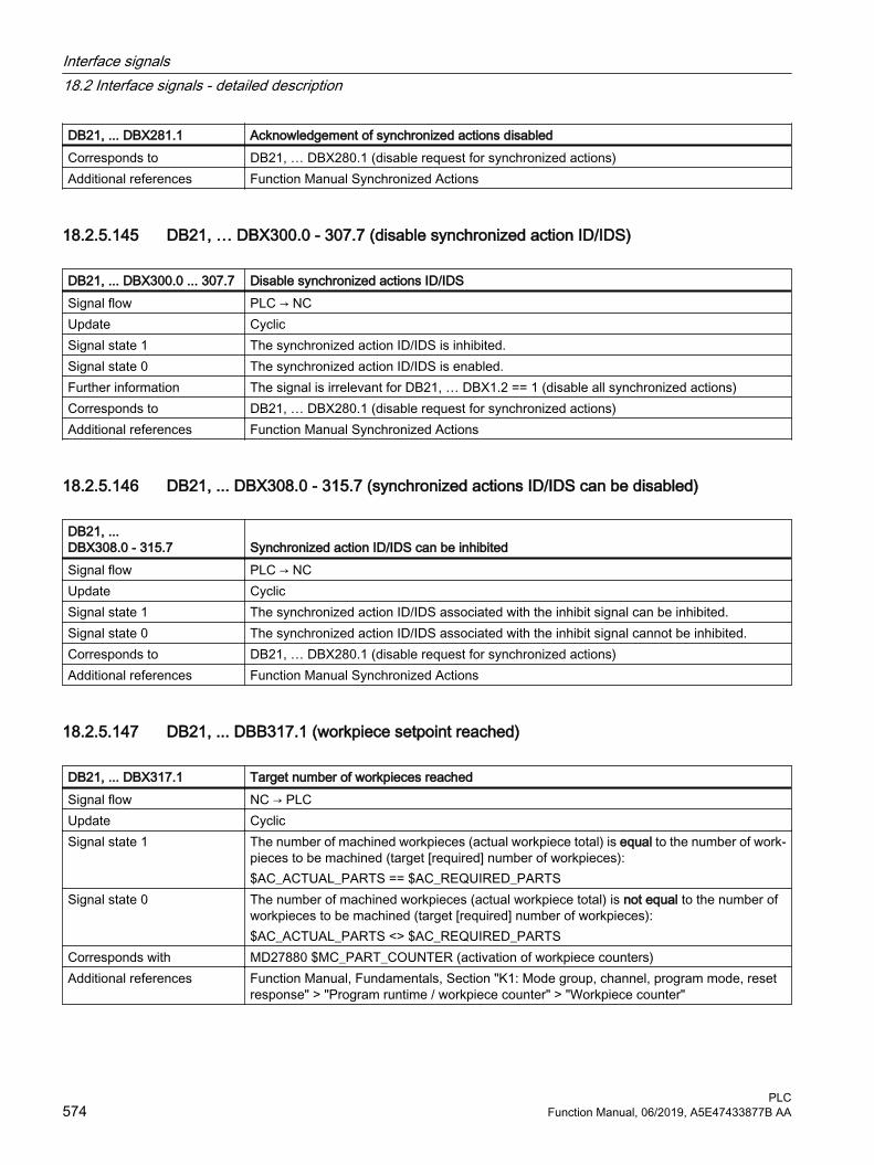
DB21, ... DBX281.1 Acknowledgement of synchronized actions disabledCorresponds to DB21, … DBX280.1 (disable request for synchronized actions)Additional references Function Manual Synchronized Actions
18.2.5.145 DB21, … DBX300.0 - 307.7 (disable synchronized action ID/IDS)
DB21, ... DBX300.0 ... 307.7 Disable synchronized actions ID/IDSSignal flow PLC → NCUpdate CyclicSignal state 1 The synchronized action ID/IDS is inhibited.Signal state 0 The synchronized action ID/IDS is enabled.Further information The signal is irrelevant for DB21, … DBX1.2 == 1 (disable all synchronized actions)Corresponds to DB21, … DBX280.1 (disable request for synchronized actions)Additional references Function Manual Synchronized Actions
18.2.5.146 DB21, ... DBX308.0 - 315.7 (synchronized actions ID/IDS can be disabled)
DB21, ... DBX308.0 - 315.7 Synchronized action ID/IDS can be inhibitedSignal flow PLC → NCUpdate CyclicSignal state 1 The synchronized action ID/IDS associated with the inhibit signal can be inhibited.Signal state 0 The synchronized action ID/IDS associated with the inhibit signal cannot be inhibited.Corresponds to DB21, … DBX280.1 (disable request for synchronized actions)Additional references Function Manual Synchronized Actions
18.2.5.147 DB21, ... DBB317.1 (workpiece setpoint reached)
DB21, ... DBX317.1 Target number of workpieces reached Signal flow NC → PLCUpdate CyclicSignal state 1 The number of machined workpieces (actual workpiece total) is equal to the number of work‐
pieces to be machined (target [required] number of workpieces):$AC_ACTUAL_PARTS == $AC_REQUIRED_PARTS
Signal state 0 The number of machined workpieces (actual workpiece total) is not equal to the number of workpieces to be machined (target [required] number of workpieces):$AC_ACTUAL_PARTS <> $AC_REQUIRED_PARTS
Corresponds with MD27880 $MC_PART_COUNTER (activation of workpiece counters)Additional references Function Manual, Fundamentals, Section "K1: Mode group, channel, program mode, reset
response" > "Program runtime / workpiece counter" > "Workpiece counter"
Interface signals18.2 Interface signals - detailed description
PLC574 Function Manual, 06/2019, A5E47433877B AA

18.2.5.148 DB21, ... DBX317.6 (PTP traversing active)
DB21, ... DBX317.6 PTP traversing activeSignal flow NC → PLCEdge change 0 → 1 PTP (Point-To-Point) traversing is active.Edge change 1 → 0 CP (Continuous Path) traversing is active.Additional information Note
DB21, ... DBX317.6 is only relevant in the JOG mode when the transformation is active.Corresponds with DB21, ... DBX29.4 (activate PTP travel)Additional references Function Manual, Extended Functions; Chapter "M1: Kinematic transformation"
18.2.5.149 DB21, ... DBX317.7 (TOOLMAN: Tool missing)
DB21, ... DBX317.7 TOOLMAN: Tool missingSignal flow NC → PLCUpdate Job-controlledSignal state 1 The programmed tool is missing.Signal state 0 Irrelevant.Additional information A tool is either missing or cannot be used.
18.2.5.150 DB21, ... DBX318.0 (ASUB is stopped)
DB21, ... DBX318.0 ASUB is stoppedSignal flow NC → PLCUpdate CyclicSignal state 1 The ASUB is in the "stopped" state.
NoteThe ASUB was stopped by the control system before it was completely executed.
Signal state 0 The ASUB is not in the "stopped" state.NoteFor the following events, the signal is always set to 0:● NC start● Channel reset
Additional information The interface signal is only processed in the following states: ● AUTOMATIC or MDI mode:● Channel state "interrupted"● Program state"stopped"
Additional references Basic Functions Function Manual; Chapter "K1: Mode group, program mode, reset response" > "Asynchronous subprogram (ASUBs)" > "Function" > "ASUB with REPOSA"
Interface signals18.2 Interface signals - detailed description
PLCFunction Manual, 06/2019, A5E47433877B AA 575

18.2.5.151 DB21, ... DBX318.1 (block search via program test is active (SERUPRO))
DB21, ... DBX318.1 Block search via program test is active (SERUPRO)Signal flow NC → PLCUpdate CyclicSignal state 1 Block search via program test is active
During processing of the blocks as part of the block search (internal channel state: "Program test"), the interface signal is set up until the target block is changed to in the main run (program state: "stopped") .
Signal state 0 Block search via program test is not activeWhen the target block is changed to in the main run (internal channel state "Program test" is deselected; stop condition: "Search target found" is displayed), the interface signal is reset.
Additional information The block search (SERUPRO) can only be activated in AUTOMATIC mode in program state "Aborted".
Additional references Basic Functions Function Manual; Chapter "K1: mode group, channel, program mode, reset response"
18.2.5.152 DB21, ... DBX318.2 (online tool length compensation (TOFF) active)
DB21, ... DBX318.2 Online tool length compensation (TOFF) activeSignal flow NC → PLCUpdate CyclicSignal state 1 Online tool length compensation (TOFF) is active.Signal state 0 Online tool length compensation (TOFF) is not active.Additional information Using the online tool length correction, effective tool lengths can be changed in real time so
that the length changes are also considered for changes in orientation of the tool.Application areas:● Orientation transformations (TRAORI)● Orientable toolholder (TCARR)
Corresponds with DB21, ... DBX318.3 (online tool length compensation (TOFF): Compensation motion active)Additional references Function Manual, Special Functions; Chapter "F2: Multi-axis transformations"
18.2.5.153 DB21, ... DBX318.3 (online tool length compensation (TOFF): Compensation motion active)
DB21, ... DBX318.3 Online tool length compensation (TOFF): Compensation motion activeSignal flow NC → PLCUpdate CyclicSignal state 1 Compensation motion active.Signal state 0 Compensation motion is not active.Additional information If, for active online tool length compensation (DB21, ... DBX318.2 == 1), compensation motion
is active, then the interface signal is set to "1":DB21, ... DBX318.3 == 1
Interface signals18.2 Interface signals - detailed description
PLC576 Function Manual, 06/2019, A5E47433877B AA

DB21, ... DBX318.3 Online tool length compensation (TOFF): Compensation motion activeCorresponds with DB21, ... DBX318.2 (online tool length compensation (TOFF) active)Additional references Function Manual, Special Functions; Chapter "F2: Multi-axis transformations"
18.2.5.154 DB21, ... DBX318.5 (associated M0 / M1 active)
DB21, ... DBX318.5 Associated auxiliary function is active Signal flow NC → PLCUpdate CyclicSignal state 1 "Associated auxiliary function" is active.Signal state 0 Associated auxiliary function is not active.Additional information "Associated auxiliary function" (M-1) is selected from the SINUMERIK Operate user interface
in the operating area "Automatic" > "Program control" by setting the HMI/PLC interface signal DB21, ... DBX24.4.The interface signal is transferred according to the value of the FB1 parameter MMCToIf by the basic PLC program into the NC/PLC interface signal DB21, ... DBX30.5:● "TRUE": Transmission● "FALSE": No transmissionThe default value of the parameter is "TRUE".
Corresponds with DB21, ... DBX24.4 (associated auxiliary function selected)DB21, ... DBX30.5 (activate associated auxiliary function)MD22254 $MC_AUXFU_ASSOC_M0_VALUE (additional M function for program stop)MD22256 $MC_AUXFU_ASSOC_M1_VALUE (additional M function for conditional stop)
Additional references Function Manual, Basic Functions; Chapter "H2: Auxiliary function outputs to PLC"
18.2.5.155 DB21, ... DBX319.0 (REPOS mode change acknowledgment)
DB21, ... DBX319.0 REPOS mode change acknowledgmentSignal flow NC → PLCUpdate CyclicSignal state 1 The acknowledgment of the REPOS mode change is available.
The interface signal DB21, ... DBX31.4 (REPOS mode change) identified by the NC is ac‐knowledged if the requested REPOS mode DB21, ... DBX31.0-2 and delay signal DB31, ... DBX10.0 were accepted in the NC. The signal states refer to the actual main run block
Signal state 0 The acknowledgment of the REPOS mode change is not available.The SERUPRO-ASUB stops automatically before REPOS and DB21, ... DBX31.4 (REPOS mode change) does not affect the SERUPRO approach.
Interface signals18.2 Interface signals - detailed description
PLCFunction Manual, 06/2019, A5E47433877B AA 577

DB21, ... DBX319.0 REPOS mode change acknowledgmentCorresponds with DB21, ... DBX25.4 (REPOS mode activation)
DB21, ... DBX31.0 - 2 (REPOS mode)DB21, ... DBX31.4 (REPOS mode change)DB31, ... DBX10.0 (REPOS delay)DB31, ... DBX72.0 (REPOS delay)DB21, ... DBX319.1 - 3 (active REPOS mode)DB21, ... DBX319.5 (REPOS acknowledgment delay)DB31, ... DBX70.0 (REPOS offset)DB31, ... DBX70.1 (REPOS offset valid)DB31, ... DBX70.2 (REPOS delay acknowledgment)MD11470 $MN_REPOS_MODE_MASK (repositioning properties)
Additional references Basic Functions Function Manual; Chapter "K1: mode group, channel, program mode, reset response"
18.2.5.156 DB21, ... DBX319.1 - 3 (active REPOS mode)
DB21, ... DBX319.1 - 3 Active REPOS modeSignal flow NC → PLCUpdate CyclicAdditional information Active REPOS mode:
Bit 3 Bit 2 Bit 1 Active REPOS approach mode0 0 0 No REPOS approach mode active0 0 1 Reposition to start of block RMBBL0 1 0 Reposition to interrupt point RMIBL0 1 1 Reposition to end of block RMEBL1 0 0 Reposition to nearest path point RMNBL
Corresponds with DB21, ... DBX25.4 (REPOS mode activation)DB21, ... DBX31.0 - 2 (REPOS mode)DB21, ... DBX31.4 (REPOS mode change)DB31, ... DBX10.0 (REPOS delay)DB31, ... DBX72.0 (REPOS delay)DB21, ... DBX319.0 (REPOS mode change acknowledgment)DB21, ... DBX319.5 (REPOS acknowledgment delay)DB31, ... DBX70.0 (REPOS offset)DB31, ... DBX70.1 (REPOS offset valid)DB31, ... DBX70.2 (REPOS delay acknowledgment)MD11470 $MN_REPOS_MODE_MASK (repositioning properties)
Additional references Basic Functions Function Manual; Chapter "K1: Mode group, channel, program mode, reset response" > "Block search type 5 (SERUPRO)" > "Repositioning to the contour (REPOS)"
Interface signals18.2 Interface signals - detailed description
PLC578 Function Manual, 06/2019, A5E47433877B AA

18.2.5.157 DB21, ... DBX319.5 (REPOS delay)
DB21, ...DBX319.5 REPOS delaySignal flow NC → PLCUpdate CyclicSignal state 1 A REPOS delay is active.Signal state 0 A REPOS delay is not active.Additional information All axes currently controlled by this channel have either no REPOS offset or their REPOS
offsets are not traversed through.Corresponds with DB21, ... DBX25.4 (REPOS mode activation)
DB21, ... DBX31.0 - 2 (REPOS mode)DB21, ... DBX31.4 (REPOS mode change)DB31, ... DBX10.0 (REPOS delay)DB31, ... DBX72.0 (REPOS delay)DB21, ... DBX319.0 (REPOS mode change acknowledgment)DB21, ... DBX319.1 - 3 (active REPOS mode)DB31, ... DBX70.0 (REPOS offset)DB31, ... DBX70.1 (REPOS offset valid)DB31, ... DBX70.2 (REPOS delay acknowledgment)MD11470 $MN_REPOS_MODE_MASK (repositioning properties)
Additional references Basic Functions Function Manual; Chapter "K1: mode group, channel, program mode, reset response"
18.2.5.158 DB21, ... DBX320.0 - 2 (orientation axis 1: activate handwheel)
DB21, ... DBX320.0 - 2 Orientation axis 1: Activate handwheelSignal flow PLC → NCUpdate Cyclic
Interface signals18.2 Interface signals - detailed description
PLCFunction Manual, 06/2019, A5E47433877B AA 579

DB21, ... DBX320.0 - 2 Orientation axis 1: Activate handwheelAdditional information The interface can be interpreted either bit or binary-coded. The definition is realized using
machine data MD11324.Bit coded: maximum 3 handwheels Bit 2 Bit 1 Bit 0 Number of the assigned handwheel
0 0 0 No handwheel assignment0 0 1 10 1 0 21 0 0 3
Binary coded: maximum 6 handwheels Bit 2 Bit 1 Bit 0 Number of the assigned handwheel
0 0 0 No handwheel assignment0 0 1 10 1 0 20 1 1 31 0 0 41 0 1 51 1 0 6
NoteAt any one time, an axis can only be assigned to one handwheel. If, for bit coding, several interface signals are set simultaneously, then the following priority applies: "Handwheel 1" before "Handwheel 2" before "Handwheel 3".
Corresponds with DB21, ... DBX324.0 - 2 (orientation axis 2: activate handwheel)DB21, ... DBX328.0 - 2 (orientation axis 3: activate handwheel)DB21, ... DBX332.0 - 2 (orientation axis 1: handwheel active)DB21, ... DBX336.0 - 2 (orientation axis 2: handwheel active)DB21, ... DBX340.0 - 2 (orientation axis 3: handwheel active)MD11324 $MN_HANDWH_VDI_REPRESENTATION (representation of the handwheel num‐ber at the VDI interface)
Additional references Function Manual, Extended Functions; Chapter "H1: manual and handwheel travel"
18.2.5.159 DB21, ... DBX320.4 (orientation axis 1: traversing key lock)
DB21, ... DBX320.4 Orientation axis 1: Traversing key lockSignal flow PLC → NCUpdate CyclicSignal state 1 The traversing key lock for the orientation axis is active.Signal state 0 The traversing key lock for the orientation axis is not active.Additional information Note
When the traversing key disable is activated while traversing, then traversing is canceled.
Interface signals18.2 Interface signals - detailed description
PLC580 Function Manual, 06/2019, A5E47433877B AA

DB21, ... DBX320.4 Orientation axis 1: Traversing key lockCorresponds with DB21, ... DBX324.4 (orientation axis 2: traversing key lock)
DB21, ... DBX328.4 (orientation axis 3: traversing key lock)DB21, ... DBX320.6 - 7 (orientation axis 1: traversing keys "Plus" / "Minus")DB21, ... DBX324.6 - 7 (orientation axis 2: traversing keys "Plus" / "Minus")DB21, ... DBX328.6 - 7 (orientation axis 3: traversing keys "Plus" / "Minus")
Additional references Function Manual, Extended Functions; Chapter "H1: manual and handwheel travel"
18.2.5.160 DB21, ... DBX320.5 (orientation axis 1: rapid traverse override)
DB21, ... DBX320.5 Orientation axis 1: Rapid traverse overrideSignal flow PLC → NCUpdate CyclicSignal state 1 When manually traversing the orientation axis using the traversing keys, when the interface
signal is set, rapid traverse velocity becomes active (MD32010). Signal state 0 When manually traversing the orientation axis using the traversing keys, the entered JOG
velocity becomes active (SD41110 or MD32020).Additional information The signal is only active for continuous or incremental manual traversing in the JOG mode.
The rapid traverse velocity can be influenced using the rapid traverse override switch.Corresponds with DB21, ... DBX324.5 (orientation axis 2: rapid traverse override)
DB21, ... DBX328.5 (orientation axis 3: rapid traverse override)DB21, ... DBX320.6 - 7 (orientation axis 1: traversing keys "Plus" / "Minus")DB21, ... DBX324.6 - 7 (orientation axis 2: traversing keys "Plus" / "Minus")DB21, ... DBX328.6 - 7 (orientation axis 3: traversing keys "Plus" / "Minus")MD32010 $MA_JOG_VELO_RAPID (conventional rapid traverse)MD32020 $MA_JOG_VELO (conventional axis velocity)SD41110 $SN_JOG_SET_VELO (axis velocity for JOG)
Additional references Function Manual, Basic Functions; Chapter "V1: Feedrates"Function Manual, Extended Functions; Chapter "H1: manual and handwheel travel"
18.2.5.161 DB21, ... DBX320.6 - 7 (Orientierungsachse 1: traversing keys "Plus" / "Minus")
DB21, ... DBX320.6 - 7 Orientation axis 1: traversing keys "Plus" / "Minus"Signal flow PLC → NCUpdate CyclicSignal state 1 A request has been made to traverse the orientation axis using the traversing key in the
positive/negative axis direction.Signal state 0 A request has not been made to traverse the orientation axis using the traversing key in the
positive/negative axis direction.
Interface signals18.2 Interface signals - detailed description
PLCFunction Manual, 06/2019, A5E47433877B AA 581

DB21, ... DBX320.6 - 7 Orientation axis 1: traversing keys "Plus" / "Minus"Additional information There is a request signal for every traversing key and/or axis direction:
Bit 6 Traversing key "Minus" (for traversing in the negative axis direction)Bit 7 Traversing key "Plus" (for traversing in the positive axis direction)
Depending on the active machine function, as well as the settings for jog and continuous operation (SD41050 and MD11300), different responses are initiated when the signal changes:1. Continuous manual travel in the jog mode
The orientation axis traverses in the direction concerned to the active limit switch as long as the interface signal is set to 1.
2. Continuous manual travel in continuous operationAt the first edge change 0 →1, the orientation axis starts to traverse in the appropriate direction. This traversing movement still continues when the edge changes from 1 → 0. Any new signal edge change 0 → 1 (same traversing direction!) stops the traversing movement.
3. Incremental manual travel in the jog modeWith signal 1 the orientation axis starts to traverse the set increment. If the signal changes to the 0 state before the increment is traversed, then traversing is interrupted. When the signal state changes to 1 again, traversing is continued. The orientation axis can be stopped and started several times as described above until it has traversed the complete increment.
4. Incremental manual travel in continuous operationAt the first edge change 0 → 1 the orientation axis starts to traverse the set increment. If another edge change 0 → 1 is performed with the same traverse signal before the orientation axis has traversed the increment, the traversing movement will be cancelled. The increment is no longer traversed to the end.
Note● The interface signal is irrelevant in operating modes:
– AUTOMATIC – MDI
● If both traversing signals ("plus" and "minus") are set at the same time there is no traversing or the current traversing is aborted.
● In contrast to machine axes, for orientation axes, only one orientation axis can be traversed at any one time using the traversing keys.
● Using DB21, ... DBX320.4, 324.4, 328.4 (orientation axis 1, 2, 3: Traversing key lock) traversing using traversing keys can be locked.
● In the following cases, the orientation axis cannot be traversed in the JOG operating mode:– The orientation axis is already being traversed via the axis-specific interface as
machine axis.– If another orientation axis is already being traversed with the traversing keys.
Interface signals18.2 Interface signals - detailed description
PLC582 Function Manual, 06/2019, A5E47433877B AA

DB21, ... DBX320.6 - 7 Orientation axis 1: traversing keys "Plus" / "Minus"Corresponds with DB21, ... DBX324.6 - 7 (orientation axis 2: traversing keys "Plus" / "Minus")
DB21, ... DBX328.6 - 7 (orientation axis 3: traversing keys "Plus" / "Minus")DB21, ... DBX320.4 (orientation axis 1: traversing key lock)DB21, ... DBX324.4 (orientation axis 2: traversing key lock)DB21, ... DBX328.4 (orientation axis 3: traversing key lock)DB31, ... DBX4.6 - 7 (traversing keys "Plus" / "Minus")MD11300 $MN_JOG_INC_MODE_LEVELTRIGGRD (INC and REF in jog mode)SD41050 $SN_JOG_CONT_MODE_LEVELTRIGGRD (jog/continuous operation for JOG, continuous)
Additional references Function Manual, Extended Functions; Chapter "H1: manual and handwheel travel"
18.2.5.162 DB21, ... DBX321.0 - 6 (orientation axis 1: machine function request)
DB21, ... DBX321.0 - 6 Orientation axis 1: machine function requestSignal flow PLC → NCUpdate CyclicSignal state 1 A request has been made to manually traverse the orientation axis.Signal state 0 A request has not been made to manually traverse the orientation axis.Additional information There is a request signal for every machine function to manually traverse the orientation axis
in the JOG mode.Bit 0 INC1Bit 1 INC10Bit 2 INC100Bit 3 INC1000Bit 4 INC10000Bit 5 INCvarBit 6 Continuous manual travel
Incremental manual travelIn addition to five fixed increment sizes (default setting in MD11330: INC1, INC10, INC100, INC1000 and INC10000), a variable increment size (INCvar) that can be set via the setting data SD41010 is also available. The distance evaluation of one increment for fixed and vari‐able increment sizes is performed via the axis-specific machine data MD31090.When pressing the "Plus" or "Minus" traversing key, or by rotating the electronic handwheel, the orientation axis starts to traverse in the appropriate direction, corresponding to the number of increments of the active machine function.Continuous manual travelFor continuous manual travel, the plus and minus traversing keys are selected to move the orientation axis continuously and the appropriate direction. Notes● If several requests are set simultaneously, no machine function becomes active.● If an orientation axis is currently being traversed via a machine function, the movement is
aborted through deselection or change of the machine function.
Interface signals18.2 Interface signals - detailed description
PLCFunction Manual, 06/2019, A5E47433877B AA 583

DB21, ... DBX321.0 - 6 Orientation axis 1: machine function requestCorresponds with DB21, ... DBX325.0 - 6 (orientation axis 2: machine function request)
DB21, ... DBX329.0 - 6 (orientation axis 3: machine function request)DB21, ... DBX333.0 - 6 (orientation axis 1: active machine function)DB21, ... DBX337.0 - 6 (orientation axis 2: active machine function)DB21, ... DBX341.0 - 6 (orientation axis 3: active machine function)MD11320 $MN_HANDWH_IMP_PER_LATCH (handwheel pulses per detent position)MD11330 $MN_JOG_INCR_SIZE_TAB (increment size for INC/handwheel)MD31090 $MA_JOG_INCR_WEIGHT (evaluation of an increment for INC/handwheel)SD41010 $SN_JOG_VAR_INCR_SIZE (size of the variable increment for JOG)
Additional references Function Manual, Extended Functions; Chapter "H1: manual and handwheel travel"
18.2.5.163 DB21, … DBX323.0 (orientation axis 1: invert handwheel direction of rotation)
DB21, ... DBX323.0 Orientation axis 1: invert handwheel direction of rotationSignal flow PLC → NCUpdate CyclicSignal state 1 A request has been made to invert the direction of rotation of the assigned handwheel.Signal state 0 A request has not been made to invert the direction of rotation of the assigned handwheel.Additional information Note
It is only permissible to change the interface signal when the orientation axis is at a standstill.Application examples● The handwheel direction of rotation should match the axis direction of motion.● A handwheel is assigned to several axes with different orientations.
Corresponds with DB21, … DBX327.0 (orientation axis 2: invert handwheel direction of rotation)DB21, … DBX331.0 (orientation axis 3: invert handwheel direction of rotation)DB21, ... DBX335.0 (orientation axis 1: handwheel direction of rotation inversion active)DB21, ... DBX339.0 (orientation axis 2: handwheel direction of rotation inversion active)DB21, ... DBX343.0 (orientation axis 3: handwheel direction of rotation inversion active)
Additional references Function Manual, Extended Functions; Chapter "H1: manual and handwheel travel"
18.2.5.164 DB21, ... DBX324.0 - 2 (orientation axis 2: activate handwheel)
DB21, ... DBX324.0 - 2 Orientation axis 2: Activate handwheelAdditional information See DB21, ... DBX320.0 - 2 (orientation axis 1: activate handwheel) (Page 579).
18.2.5.165 DB21, ... DBX324.4 (orientation axis 2: traversing key lock)
DB21, ... DBX324.4 Orientation axis 2: Traversing key lockAdditional information See DB21, ... DBX320.4 (orientation axis 1: traversing key lock) (Page 580).
Interface signals18.2 Interface signals - detailed description
PLC584 Function Manual, 06/2019, A5E47433877B AA

18.2.5.166 DB21, ... DBX324.5 (orientation axis 2: rapid traverse override)
DB21, ... DBX324.5 Orientation axis 2: Rapid traverse overrideAdditional information See DB21, ... DBX320.5 (orientation axis 1: rapid traverse override) (Page 581).
18.2.5.167 DB21, ... DBX324.6 - 7 (orientation axis 2: traversing keys "Plus" / "Minus")
DB21, ... DBX324.6 - 7 Orientation axis 2: traversing keys "Plus" / "Minus"Additional information See DB21, ... DBX320.6 - 7 (Orientierungsachse 1: traversing keys "Plus" / "Mi‐
nus") (Page 581).
18.2.5.168 DB21, ... DBX325.0 - 6 (orientation axis 2: machine function request)
DB21, ... DBX325.0 - 6 Orientation axis 2: machine function requestAdditional information See DB21, ... DBX321.0 - 6 (orientation axis 1: machine function request) (Page 583).
18.2.5.169 DB21, … DBX327.0 (orientation axis 2: invert handwheel direction of rotation)
DB21, ... DBX327.0 Orientation axis 2: invert handwheel direction of rotationAdditional information See DB21, … DBX323.0 (orientation axis 1: invert handwheel direction of rotation)
(Page 584).
18.2.5.170 DB21, ... DBX328.0 - 2 (orientation axis 3: activate handwheel)
DB21, ... DBX328.0 - 2 Orientation axis 3: Activate handwheelAdditional information See DB21, ... DBX320.0 - 2 (orientation axis 1: activate handwheel) (Page 579).
18.2.5.171 DB21, ... DBX328.4 (orientation axis 3: traversing key lock)
DB21, ... DBX328.4 Orientation axis 3: Traversing key lockAdditional information See DB21, ... DBX320.4 (orientation axis 1: traversing key lock) (Page 580).
18.2.5.172 DB21, ... DBX328.5 (orientation axis 3: rapid traverse override)
DB21, ... DBX328.5 Orientation axis 3: Rapid traverse overrideAdditional information See DB21, ... DBX320.5 (orientation axis 1: rapid traverse override) (Page 581).
Interface signals18.2 Interface signals - detailed description
PLCFunction Manual, 06/2019, A5E47433877B AA 585

18.2.5.173 DB21, ... DBX328.6 - 7 (orientation axis 3: traversing keys "Plus" / "Minus")
DB21, ... DBX328.6 - 7 Orientation axis 3: traversing keys "Plus" / "Minus"Additional information See DB21, ... DBX320.6 - 7 (Orientierungsachse 1: traversing keys "Plus" / "Minus")
(Page 581).
18.2.5.174 DB21, ... DBX329.0 - 6 (orientation axis 3: machine function request)
DB21, ... DBX329.0 - 6 Orientation axis 3: machine function requestAdditional information See DB21, ... DBX321.0 - 6 (orientation axis 1: machine function request) (Page 583).
18.2.5.175 DB21, … DBX331.0 (orientation axis 3: invert handwheel direction of rotation)
DB21, ... DBX331.0 Orientation axis 3: invert handwheel direction of rotationAdditional information See DB21, … DBX323.0 (orientation axis 1: invert handwheel direction of rotation)
(Page 584).
18.2.5.176 DB21, ... DBX332.0 - 2 (orientation axis 1: handwheel active)
DB21, ... DBX332.0 - 2 Orientation axis 1: handwheel activeSignal flow NC → PLCUpdate Cyclic
Interface signals18.2 Interface signals - detailed description
PLC586 Function Manual, 06/2019, A5E47433877B AA

DB21, ... DBX332.0 - 2 Orientation axis 1: handwheel activeAdditional information The interface can be interpreted either bit or binary-coded. The definition is realized using
machine data MD11324.Bit coded: maximum 3 handwheels Bit 2 Bit 1 Bit 0 Number of the assigned handwheel
0 0 0 No handwheel assignment0 0 1 10 1 0 21 0 0 3
Binary coded: maximum 6 handwheels Bit 2 Bit 1 Bit 0 Number of the assigned handwheel
0 0 0 No handwheel assignment0 0 1 10 1 0 20 1 1 31 0 0 41 0 1 51 1 0 6
NoteAt any one time, an axis can only be assigned to one handwheel. If, for bit coding, several interface signals are set simultaneously, then the following priority applies: "Handwheel 1" before "Handwheel 2" before "Handwheel 3".
Corresponds with DB21, ... DBX336.0 - 2 (orientation axis 2: handwheel active)DB21, ... DBX340.0 - 2 (orientation axis 3: handwheel active)DB21, ... DBX320.0 - 2 (orientation axis 2: activate handwheel)DB21, ... DBX324.0 - 2 (orientation axis 2: activate handwheel)DB21, ... DBX328.0 - 2 (orientation axis 3: activate handwheel)MD11324 $MN_HANDWH_VDI_REPRESENTATION (representation of the handwheel num‐ber at the VDI interface)
Additional references Function Manual, Extended Functions; Chapter "H1: manual and handwheel travel"
18.2.5.177 DB21, ... DBX332.4 - 5 (orientation axis 1: traversing request "Plus" / "Minus")
DB21, ... DBX332.4 - 5 Orientation axis 1: traversing request "Plus" / "Minus"Signal flow NC → PLCUpdate CyclicSignal state 1 There is a traversing request available for the orientation axis.Signal state 0 There is no traversing request available for the orientation axis.
Interface signals18.2 Interface signals - detailed description
PLCFunction Manual, 06/2019, A5E47433877B AA 587

DB21, ... DBX332.4 - 5 Orientation axis 1: traversing request "Plus" / "Minus"Additional information The traversing request is initiated in different ways depending on the operating mode:
● JOG mode"Plus" or "Minus" traversing key
● REF modeTraversing key that initiates traversing motion in the direction of the reference point.
● AUTOMATIC or MDI modeA program block with a traversing operation is executed for an orientation axis.
There is a signal for each axis direction:Bit 4 Traversing request "Minus" (for traversing in the negative axis direction)Bit 5 Traversing key "Plus" (for traversing in the positive axis direction)
Corresponds with DB21, ... DBX336.4 - 5 (orientation axis 2: traversing request "Plus" / "Minus")DB21, ... DBX340.4 - 5 (orientation axis 3: traversing request "Plus" / "Minus")DB21, ... DBX320.6 - 7 (orientation axis 1: traversing keys "Plus" / "Minus")DB21, ... DBX324.6 - 7 (orientation axis 2: traversing keys "Plus" / "Minus")DB21, ... DBX328.6 - 7 (orientation axis 3: traversing keys "Plus" / "Minus")DB21, ... DBX332.6 - 7 (orientation axis 1: traversing command "Plus" / "Minus")DB21, ... DBX336.6 - 7 (orientation axis 2: traversing command "Plus" / "Minus")DB21, ... DBX340.6 - 7 (orientation axis 3: traversing command "Plus" / "Minus")
Additional references Function Manual, Extended Functions; Chapter "H1: manual and handwheel travel"
18.2.5.178 DB21, ... DBX332.6 - 7 (orientation axis 1: traversing command "Plus" / "Minus"
DB21, ... DBX332.6 - 7 Orientation axis 1: traversing command "Plus" / "Minus"Signal flow NC → PLCUpdate CyclicSignal state 1 There is a traversing request for the orientation axis or the orientation axis is traversing.Signal state 0 There is no traversing request for the orientation axis or the orientation axis is not traversing.Additional information Depending on the setting of MD17900, bit 0, the traversing command is already output if a
"Traversing request" is active (bit 0 = 0) or only if the axis is actually traversing (bit 0 = 1).There is a signal for each axis direction:
Bit 6 Traversing command "Minus" (for traversing in the negative axis direction)Bit 7 Traversing command "Plus" (for traversing in the positive axis direction)
Application exampleReleasing the axis clamp when the traversing command is identified.NoteFor axes where clamping is not released until a drive command is detected, the continuous-path mode (G64) is not possible.
Interface signals18.2 Interface signals - detailed description
PLC588 Function Manual, 06/2019, A5E47433877B AA
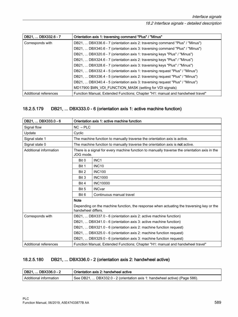
DB21, ... DBX332.6 - 7 Orientation axis 1: traversing command "Plus" / "Minus"Corresponds with DB21, ... DBX336.6 - 7 (orientation axis 2: traversing command "Plus" / "Minus")
DB21, ... DBX340.6 - 7 (orientation axis 3: traversing command "Plus" / "Minus")DB21, ... DBX320.6 - 7 (orientation axis 1: traversing keys "Plus" / "Minus")DB21, ... DBX324.6 - 7 (orientation axis 2: traversing keys "Plus" / "Minus")DB21, ... DBX328.6 - 7 (orientation axis 3: traversing keys "Plus" / "Minus")DB21, ... DBX332.4 - 5 (orientation axis 1: traversing request "Plus" / "Minus")DB21, ... DBX336.4 - 5 (orientation axis 2: traversing request "Plus" / "Minus")DB21, ... DBX340.4 - 5 (orientation axis 3: traversing request "Plus" / "Minus")MD17900 $MN_VDI_FUNCTION_MASK (setting for VDI signals)
Additional references Function Manual, Extended Functions; Chapter "H1: manual and handwheel travel"
18.2.5.179 DB21, ... DBX333.0 - 6 (orientation axis 1: active machine function)
DB21, ... DBX333.0 - 6 Orientation axis 1: active machine functionSignal flow NC → PLCUpdate CyclicSignal state 1 The machine function to manually traverse the orientation axis is active.Signal state 0 The machine function to manually traverse the orientation axis is not active.Additional information There is a signal for every machine function to manually traverse the orientation axis in the
JOG mode.Bit 0 INC1Bit 1 INC10Bit 2 INC100Bit 3 INC1000Bit 4 INC10000Bit 5 INCvarBit 6 Continuous manual travel
NoteDepending on the machine function, the response when actuating the traversing key or the handwheel differs.
Corresponds with DB21, ... DBX337.0 - 6 (orientation axis 2: active machine function)DB21, ... DBX341.0 - 6 (orientation axis 3: active machine function)DB21, ... DBX321.0 - 6 (orientation axis 2: machine function request)DB21, ... DBX325.0 - 6 (orientation axis 2: machine function request)DB21, ... DBX329.0 - 6 (orientation axis 3: machine function request)
Additional references Function Manual, Extended Functions; Chapter "H1: manual and handwheel travel"
18.2.5.180 DB21, ... DBX336.0 - 2 (orientation axis 2: handwheel active)
DB21, ... DBX336.0 - 2 Orientation axis 2: handwheel activeAdditional information See DB21, ... DBX332.0 - 2 (orientation axis 1: handwheel active) (Page 586).
Interface signals18.2 Interface signals - detailed description
PLCFunction Manual, 06/2019, A5E47433877B AA 589

18.2.5.181 DB21, ... DBX336.4 - 5 (orientation axis 2: traversing request "Plus" / "Minus")
DB21, ... DBX336.4 - 5 Orientation axis 2: traversing request "Plus" / "Minus"Additional information See DB21, ... DBX332.4 - 5 (orientation axis 1: traversing request "Plus" / "Minus")
(Page 587).
18.2.5.182 DB21, ... DBX336.6 - 7 (orientation axis 2: traversing command "Plus" / "Minus"
DB21, ... DBX336.6 - 7 Orientation axis 2: traversing command "Plus" / "Minus"Additional information See DB21, ... DBX332.6 - 7 (orientation axis 1: traversing command "Plus" / "Minus"
(Page 588).
18.2.5.183 DB21, ... DBX337.0 - 6 (orientation axis 2: active machine function)
DB21, ... DBX337.0 - 6 Orientation axis 2: active machine functionAdditional information See DB21, ... DBX333.0 - 6 (orientation axis 1: active machine function) (Page 589).
18.2.5.184 DB21, ... DBX340.0 - 2 (orientation axis 3: handwheel active)
DB21, ... DBX340.0 - 2: Orientation axis 3: handwheel activeAdditional information See DB21, ... DBX332.0 - 2 (orientation axis 1: handwheel active) (Page 586).
18.2.5.185 DB21, ... DBX340.4 - 5 (orientation axis 3: traversing request "Plus" / "Minus")
DB21, ... DBX340.4 - 5: Orientation axis 3: traversing request "Plus" / "Minus"Additional information See DB21, ... DBX332.4 - 5 (orientation axis 1: traversing request "Plus" / "Minus")
(Page 587).
18.2.5.186 DB21, ... DBX340.6 - 7 (orientation axis 3: traversing command "Plus" / "Minus"
DB21, ... DBX340.6 - 7 Orientation axis 3: traversing command "Plus" / "Minus"Additional information See DB21, ... DBX332.6 - 7 (orientation axis 1: traversing command "Plus" / "Minus"
(Page 588).
18.2.5.187 DB21, ... DBX341.0 - 6 (orientation axis 3: active machine function)
DB21, ... DBX341.0 - 6 Orientation axis 3: active machine functionAdditional information See DB21, ... DBX333.0 - 6 (orientation axis 1: active machine function) (Page 589).
Interface signals18.2 Interface signals - detailed description
PLC590 Function Manual, 06/2019, A5E47433877B AA

18.2.5.188 DB21, ... DBX344.0 (TM: tool prewarning limit reached)
DB21, ... DBX344.0 TOOLMAN: Tool prewarning limit reachedSignal flow PLC → NCUpdate Job-controlledSignal state 1 The tool prewarning limit has been reached.Signal state 0 Irrelevant.Additional information The T number of the tool, whose prewarning value has been reached, is located in: DBD348
The change signal is active for one OB 1 cycle.Corresponds with DB21, ... DBX344.1 tool management change signal: T number for tool limit value
DB21, ... DBX344.2 tool management change signal: T number for the new replacement toolDB21, ... DBX344.3 tool management change signal: T number of the last replacement toolDBD348 (T number for tool prewarning limit)
Additional references Function Manual, Tool Management
18.2.5.189 DB21, ... DBX344.1 (TM: Tool limit value reached)
DB21, ... DBX344.1 TOOLMAN: Tool limit value reachedSignal flow PLC → NCUpdate Job-controlledSignal state 1 The tool limit value has been reachedSignal state 0 Irrelevant.Additional information The T number of the tool, whose limit value has been reached, is located in: DBD352
The change signal is active for one OB 1 cycle.Corresponds with DB21, ... DBX344.0 tool management change signal: T number for tool pre-alarm limit
DB21, ... DBX344.2 tool management change signal: T number for the new replacement toolDB21, ... DBX344.3 tool management change signal: T number of the last replacement toolDBD352 (T number for tool limit value)
Additional references Function Manual, Tool Management
18.2.5.190 DB21, ... DBX344.2 (TM: Transition to new replacement tool)
DB21, ... DBX344.2 TOOLMAN: Transition to new replacement toolSignal flow PLC → NCUpdate Job-controlledSignal state 1 A transition is made to a new replacement tool.Signal state 0 Irrelevant.Additional information The T number for the new replacement tool is located in: DBD356
The change signal is active for one OB 1 cycle.
Interface signals18.2 Interface signals - detailed description
PLCFunction Manual, 06/2019, A5E47433877B AA 591

DB21, ... DBX344.2 TOOLMAN: Transition to new replacement toolCorresponds with DB21, ... DBX344.0 tool management change signal: T number for tool pre-alarm limit
DB21, ... DBX344.1 tool management change signal: T number for tool limit valueDB21, ... DBX344.3 tool management change signal: T number of the last replacement toolDBD356 (T number of the replacement tool)
Additional references Function Manual, Tool Management
18.2.5.191 DB21, ... DBX344.3 (TM: Last replacement tool of the tool group)
DB21, ... DBX344.3 TOOLMAN: Last replacement tool of the tool groupSignal flow PLC → NCUpdate Job-controlledSignal state 1 The last replacement tool of the tool group has been reachedSignal state 0 Irrelevant.Additional information The T number of the last replacement tool of the tool group is located in: DBD360
The change signal is active for one OB 1 cycle.Note The monitoring for the last replacement tool must be activated in MD20310 $MC_TOOL_MANAGEMENT_MASK, bit 18.
Corresponds with DB21, ... DBX344.0 tool management change signal: T number for tool pre-alarm limitDB21, ... DBX344.1 tool management change signal: T number for tool limit valueDB21, ... DBX344.2 tool management change signal: T number for the new replacement toolDB21, ... DBD360 (T-number of the last replacement tool)
Additional references Function Manual, Tool Management
18.2.5.192 DB21, ... DBB376 (PROG_EVENT trigger event)
DB21, ...DBB376 PROG_EVENT trigger eventSignal flow NC → PLCUpdate Cyclic
Interface signals18.2 Interface signals - detailed description
PLC592 Function Manual, 06/2019, A5E47433877B AA
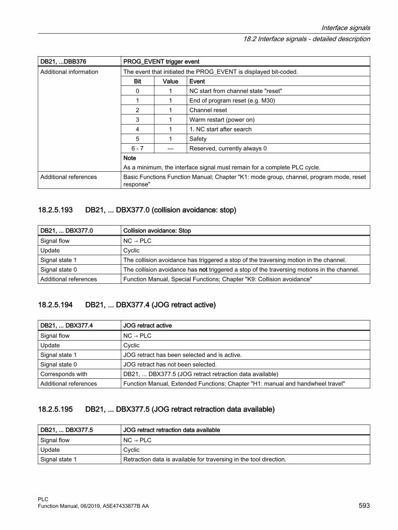
DB21, ...DBB376 PROG_EVENT trigger eventAdditional information The event that initiated the PROG_EVENT is displayed bit-coded.
Bit Value Event0 1 NC start from channel state "reset"1 1 End of program reset (e.g. M30)2 1 Channel reset3 1 Warm restart (power on)4 1 1. NC start after search5 1 Safety
6 - 7 --- Reserved, currently always 0NoteAs a minimum, the interface signal must remain for a complete PLC cycle.
Additional references Basic Functions Function Manual; Chapter "K1: mode group, channel, program mode, reset response"
18.2.5.193 DB21, ... DBX377.0 (collision avoidance: stop)
DB21, ... DBX377.0 Collision avoidance: StopSignal flow NC → PLCUpdate CyclicSignal state 1 The collision avoidance has triggered a stop of the traversing motion in the channel.Signal state 0 The collision avoidance has not triggered a stop of the traversing motions in the channel.Additional references Function Manual, Special Functions; Chapter "K9: Collision avoidance"
18.2.5.194 DB21, ... DBX377.4 (JOG retract active)
DB21, ... DBX377.4 JOG retract activeSignal flow NC → PLCUpdate CyclicSignal state 1 JOG retract has been selected and is active.Signal state 0 JOG retract has not been selected.Corresponds with DB21, ... DBX377.5 (JOG retract retraction data available)Additional references Function Manual, Extended Functions; Chapter "H1: manual and handwheel travel"
18.2.5.195 DB21, ... DBX377.5 (JOG retract retraction data available)
DB21, ... DBX377.5 JOG retract retraction data availableSignal flow NC → PLCUpdate CyclicSignal state 1 Retraction data is available for traversing in the tool direction.
Interface signals18.2 Interface signals - detailed description
PLCFunction Manual, 06/2019, A5E47433877B AA 593

DB21, ... DBX377.5 JOG retract retraction data availableSignal state 0 Retraction data is not available for traversing in the tool direction. JOG retract cannot be
selectedAdditional information If the signal state is active, then the JOG retract can be selected (user interface or PI service
"RETRAC").Corresponds with DB21, ... DBX377.4 (JOG retract active)Additional references Function Manual, Extended Functions; Chapter "H1: manual and handwheel travel"
18.2.5.196 DB21, ... DBX377.6 (JOG circular travel active)
DB21, ... DBX377.6 JOG circular travel activeSignal flow NC → PLCUpdate CyclicSignal state 1 The "Circular travel in JOG" function is active.Signal state 0 The "Circular travel in JOG" function isnot active.Corresponds with DB21, ... DBX30.6 (JOG circular travel)Additional references Function Manual, Extended Functions; Chapter "H1: manual and handwheel travel"
18.2.5.197 DB21, … DBX378.0 (ASUB active)
DB21, ... DBX378.0 ASUB is activeSignal flow NC → PLCUpdate CyclicSignal state 1 An ASUB is active.Signal state 0 No ASUB is active.Additional information Note
Also outside block FC9, feedback about a running ASUB is realized using the interface signal. Additional references Basic Functions Function Manual; Chapter "K1: Mode group, program mode, reset response"
> "Asynchronous subprograms (ASUBs)"
18.2.5.198 DB21, … DBX378.1 (stopped ASUB active)
DB21, ... DBX378.1 "Silent" ASUB is activeSignal flow NC → PLCUpdate CyclicSignal state 1 A "silent" ASUB is active.Signal state 0 No "silent" ASUB is active.Additional information A "silent" ASUB is an ASUB where blocks are not displayed on the screen as this has been
suppressed with DISPLOF.Additional references Basic Functions Function Manual; Chapter "K1: Mode group, program mode, reset response"
> "Asynchronous subprograms (ASUBs)"
Interface signals18.2 Interface signals - detailed description
PLC594 Function Manual, 06/2019, A5E47433877B AA

18.2.5.199 DB21, ... DBX384.0 (enable GOTOS)
DB21, ... DBX384.0 Enable GOTOSSignal flow PLC → NCUpdate CyclicSignal state 1 A request has been made to enable GOTOS (return jump to the program start) in the channel.Signal state 0 A request has not been made to enable GOTOS (return jump to the program start) in the
channel.NC program execution is continued with the next command following GOTOS.
Corresponds with MD27850 $MC_PROG_NET_TIMER_MODE (impact of the program runtime net counter)MD27860 $MC_PROCESSTIMER_MODE (activation of the program runtime measurement)MD27880 $MC_PART_COUNTER (activation of the workpiece counters)
Additional references Basic Functions Function Manual; Chapter "K1: Mode group, channel, program mode, reset response" > "Program mode" > "Program jumps" > "Return jump to the beginning of the program"
18.2.5.200 DB21, ... DBX385.0 - 7 (input signal 1 - 8)
DB21, ... DBX385.0 - 7 Input signal 1 - 8
Signal flow PLC → NCUpdate CyclicSignal state 1 The value of the input signal is 1 (TRUE).Signal state 0 The value of the input signal is 0 (FALSE).Further information Application: GrindingCorresponds to $AC_IN_KEY_G_ENABLE[1 ... 8] (input signal 1 - 8 enable on the NC side)Additional references Function Manual Synchronized Actions
18.2.5.201 DB21, ... DBX386.0 - 7 (disabling of input signal 1 - 8)
DB21, ... DBX386.0 - 7 Disabling of input signal 1 - 8
Signal flow PLC → NCUpdate CyclicSignal state 1 The input signal is inhibited.Signal state 0 The input signal is enabled.Further information Application: GrindingCorresponds to DB21, … DBX385.0 - 7 (input signals 1 - 8)
DB21, … DBX387.0 ... 7 (action is enabled)$AC_IN_KEY_G_ENABLE[1 ... 8] (input signal 1 - 8 enable on the NC side)
Additional references Function Manual Synchronized Actions
Interface signals18.2 Interface signals - detailed description
PLCFunction Manual, 06/2019, A5E47433877B AA 595

18.2.5.202 DB21, ... DBX387.0 - 7 (status of action 1 - 8)
DB21, ... DBX387.0 - 7 Status of action 1 - 8
Signal flow PLC → NCUpdate CyclicSignal state 1 The action is enabled.Signal state 0 The action is inhibited.Further information Application: GrindingCorresponds to DB21, … DBX391.0 - 7 (enable request for the action on the NC side)
$AC_IN_KEY_G_RUN_OUT[1 ... 8] (enable request of the action 1 - 8 on the NC side)$AC_IN_KEY_G_RUN_IN[ 1 ... 8 ] (enable of the action 1 - 8 on the PLC side)
Additional references Function Manual Synchronized Actions
18.2.5.203 DB21, ... DBX390.0 - 7 (enable status of input signal 1 - 8)
DB21, ... DBX390.0 - 7 Enable status of input signal 1 - 8
Signal flow PLC → NCUpdate CyclicSignal state 1 The input signal is enabled.
The enable signal is formed by the NC-side ANDlogic operation of the NC enable signal $AC_IN_KEY_G_ENABLE[1 ... 8] and the PLC enable signal NOT (DBX386.0 - 7).
Signal state 0 The input signal is not enabled.Further information Application: GrindingCorresponds to DB21, … DBX386.0 - 7 (disabling of input signal 1 - 8)
$AC_IN_KEY_G_ENABLE[1 ... 8] (input signal 1 - 8 enable on the NC side)$AC_IN_KEY_G_ISENABLE[1 ... 8] (release status of the input signal 1 - 8)
Additional references Function Manual Synchronized Actions
18.2.5.204 DB21, ... DBX391.0 - 7 (enable request for action 1 - 8)
DB21, ... DBX391.0 - 7 Enable request for action 1 - 8
Signal flow NC → PLCUpdate CyclicSignal state 1 It has been requested that the action is enabled.Signal state 0 It has not been requested that the action is enabled.Further information Application: Grinding
Interface signals18.2 Interface signals - detailed description
PLC596 Function Manual, 06/2019, A5E47433877B AA

DB21, ... DBX391.0 - 7 Enable request for action 1 - 8
Corresponds to DB21, … DBX387.0 - 7 (status of the action 1 - 8)$AC_IN_KEY_G_RUN_OUT[1 ... 8] (enable request of the action 1 - 8 on the NC side)$AC_IN_KEY_G_RUN_IN[1 ... 8] (enable of the action 1 - 8 on the PLC side)
Additional references Function Manual Synchronized Actions
18.2.5.205 DB21, ... DBB392 (selection: Coordinate system for Cartesian manual traversing and handwheel override in automatic mode in the tool direction (DRF))
DB21, ... DBB392 Selection: Coordinate system for Cartesian manual traversing and handwheel override in automatic mode in the tool direction (DRF)
Signal flow PLC → NCUpdate CyclicAdditional information Selection of the coordinate system for:
● Cartesian manual traversing of the geometry axes in the tool direction (TCS)● Handwheel override of the geometry axes in the AUTOMATIC mode in the tool direction
(DRF) Value Description
0 The function is not selected1 Manual traversing of the geometry axes in the basic coordinate system (BCS)2 Manual traversing of the geometry axes in the workpiece coordinate system
(WCS)3 Manual traversing or handwheel override (DRF) of the geometry axes in the
workpiece coordinate system (WCS)Additional references ● Function Manual, Basic Functions, Section:
– "K2: Axes, coordinate systems, frames" > "Coordinate systems" > "Additive offsets" > "DRF offset"
– "P3: Basic PLC program for SINUMERIK 840D sl" > Block descriptions" > "FC19: LBP_MCPCtrlMilling - Transmission of the MCP signals to the interface"
● Function Manual Extended Functions; Chapter:– "M1: Kinematic transformation" > "Cartesian manual travel"– "F2: Multi-axis transformations" > "Cartesian manual travel"– "H1: Manual and handwheel traversing" > "Using a handwheel in the automatic mode"
> "DRF offset"
Interface signals18.2 Interface signals - detailed description
PLCFunction Manual, 06/2019, A5E47433877B AA 597

18.2.6 DB31, ...: Axis/spindle
18.2.6.1 DB31, ... DBB0 (feedrate override, axis-specific)
DB31, ... DBB0 Feedrate override, axis-specificSignal flow PLC → NCUpdate Cyclic
Interface signals18.2 Interface signals - detailed description
PLC598 Function Manual, 06/2019, A5E47433877B AA

DB31, ... DBB0 Feedrate override, axis-specificAdditional information Binary/Gray coding
The override factors can be specified in the binary or Gray-coded format. The control must be informed of the used format via the following machine data:MD12000 $MN_OVR_AX_IS_GRAY_CODE = <Coding>Binary codingWith binary coding, the value in the interface corresponds to the override factor.
Binary code Decimal Override factor0000 0000 0 0.000000 0001 1 0.010000 0010 2 0.020000 0011 3 0.03000 0100 4 0.04
... ... ...0110 0100 100 1.00
... ... ...1100 1000 200 2.00
Gray codingThe Gray-coded values of the interface are assigned the override factors via the following machine data:MD12010 $MN_OVR_FACTOR_AX_SPEED[ <Switch position> - 1 ] = <Override factor>Switch position Gray code Override factor 1)
1 00001 0.002 00011 0.013 00010 0.024 00110 0.045 00111 0.066 00101 0.087 00100 0.108 01100 0.209 01101 0.3010 01111 0.4011 01110 0.5012 01010 0.6013 01011 0.7014 01001 0.7515 01000 0.8016 11000 0.8517 11001 0.9018 11011 0.9519 11010 1.0020 11110 1.0521 11111 1.1022 11101 1.15
Interface signals18.2 Interface signals - detailed description
PLCFunction Manual, 06/2019, A5E47433877B AA 599

DB31, ... DBB0 Feedrate override, axis-specific23 11100 1.2024 10100 1.2025 10101 1.2026 10111 1.2027 10110 1.2028 10010 1.2029 10011 1.2030 10001 1.2031 10000 1.20
Limitations● The active override factor is limited internally in the control to 2.00 or 200%.● The maximum possible override factor can be limited to a value less than 200% with the
following machine data:MD12100 $MN_OVR_FACTOR_LIMIT_BIN
NotesThe axis-specific feedrate override is not effective with the following functions when cutting threads: G33, G331, G332, G63
Corresponds to DB21, ... DBB4 (path feedrate override)DB31, ... DBB19 (speed override, spindle-specific)DB31, ... DBX1.7 (override active)
Additional references Basic Functions Function Manual; Section "V1: Feedrates" > "Feedrate control" > "Feedrate override from the machine control panel"
1) Default values
18.2.6.2 DB31, ... DBX1.0 (drive test travel enable)
DB31, ... DBX1.0 Drive test travel enableSignal flow PLC → NCUpdate CyclicSignal state 1 The travel enable for the drive test is set, i.e. axis motion for the drive test is enabled.Signal state 0 The travel enable for the drive test is not set, i.e. axis motion for the drive test is inhibited.Further information The signal is the feedback signal for the request:
DB31, ... DBX61.0 == 1 (drive test travel request)Only the PLC can enable an axis so that it can be traversed.
Corresponds with DB31, ... DBX61.0 (drive test travel request)Additional references SINUMERIK 840D sl Commissioning Manual, CNC Commissioning: NC, PLC, Drive
Interface signals18.2 Interface signals - detailed description
PLC600 Function Manual, 06/2019, A5E47433877B AA

18.2.6.3 DB31, ... DBX1.1 (acknowledge fixed stop reached).
DB31, ... DBX1.1 Acknowledge fixed stop reachedSignal flow PLC → NCUpdate CyclicSignal state 1 Significance when the fixed stop is reached: DB31, ... DBX62.5 (fixed stop reached) == 1
● The axis presses against the fixed stop with the clamping torque.● The fixed stop monitoring window is activated.● A block change is executed.
Signal state 0 Significance when the fixed stop is reached: DB31, ... DBX62.5 (fixed stop reached) == 1● The axis presses against the fixed stop with the clamping torque.● The fixed stop monitoring window is activate● A block change is not executed, and the channel message "Wait: HiFu acknowledgment
missing" is displayed● The function is canceled, alarm "20094 axis %1 Function aborted" is output.Significance after deselecting the function FXS=0 via the part program:● The torque limiting and the monitoring of the fixed stop monitoring window are canceled.
Additional information Irrelevant for MD37060 $MA_FIXED_STOP_ACKN_MASK == 0 or 2Corresponds with DB31, ... DBX1.2 (fixed stop sensor)
DB31, ... DBX3.1 (enable travel to fixed stop)DB31, ... DBX62.4 (activate travel to fixed stop)DB31, ... DBX62.5 (fixed stop reached)MD37060 $MA_FIXED_STOP_ACKN_MASK (monitoring PLC acknowledgements for travel to fixed stop)
Additional references Function Manual, Basic Functions; Chapter "F1: Travel to fixed stop"
18.2.6.4 DB31, ... DBX1.2 (fixed stop sensor)
DB31, ... DBX1.2 Sensor for fixed stopSignal flow PLC → NCUpdate CyclicSignal state 1 Fixed stop has been reached.Signal state 0 Fixed stop has not been reached.Additional information The signal is only active if: MD37040 $MA_FIXED_STOP_BY_SENSOR == 1Corresponds with DB31, ... DBX1.1 (acknowledge fixed stop reached).
DB31, ... DBX3.1 (enable travel to fixed stop)DB31, ... DBX62.4 (activate travel to fixed stop)DB31, ... DBX62.5 (fixed stop reached)MD37040 $MA_FIXED_STOP_BY_SENSOR = (fixed stop detection via sensor)
Additional references Function Manual, Basic Functions; Chapter "F1: Travel to fixed stop"
Interface signals18.2 Interface signals - detailed description
PLCFunction Manual, 06/2019, A5E47433877B AA 601

18.2.6.5 DB31, ... DBX1.3 (axis/spindle disable)
DB31, ... DBX1.3 Axis/spindle disableSignal flow PLC → NCUpdate Cyclic
Interface signals18.2 Interface signals - detailed description
PLC602 Function Manual, 06/2019, A5E47433877B AA

DB31, ... DBX1.3 Axis/spindle disableSignal state 1 Axis/spindle disable is requested.
Axis● Effects with stationary axis:
– No setpoints are output to the position controller, i.e. the axis traversing movement is disabled. The axis is in closed-loop position control and any remaining following error is compensated.
– If the axis is traversed via an NC program or manually, the set position and set velocity are displayed as the actual position and actual velocity on the user interface. With channel reset or end of program (M30/M2), the display of the actual value is set to the actual value of the machine axis.
– The travel commands are output to the NC/PLC interface.● Effects with traversing axis:
– The axis is stopped in compliance with the currently active braking characteristic and an alarm is displayed. Subsequently, the travel movements of the axis are disabled. Position control remains active and holds the axis in the current position.
Spindle● Effects with open-loop control mode and stationary spindle:
– No setpoints are output to the speed controller, i.e. the spindle traversing movement is disabled.
– If the spindle is traversed via an NC program or manually, the speed setpoint is displayed on the user interface as the speed actual value.
● Effects with open-loop control mode and rotating spindle:– Speed setpoint zero is immediately output to the speed controller.– The spindle is stopped in compliance with the currently active braking characteristic
and an alarm is displayed. Subsequently, the travel movements of the spindle are disabled. Position control remains active and holds the axis in the current position.
● Effects with positioning mode: See Stationary axis / Traversing axisStructure graphic
Axis/spindle disableNote● If one of the following interface signals is set for a traversing axis/spindle for which the
signal "Axis/spindle disable" is present, the axis/spindle is not stopped:– DB21, ... DBX12.3, 16.3 or 20.3 (feedrate stop for geometry axes 1, 2 and 3)– DB21, ... DBX320.3, 324.3 or 328.3 (feedrate stop for orientation axes 1, 2 and 3)
Interface signals18.2 Interface signals - detailed description
PLCFunction Manual, 06/2019, A5E47433877B AA 603

DB31, ... DBX1.3 Axis/spindle disable– DB31, ... DBX4.3 (feedrate stop / spindle stop)
● The axis/spindle can still be switched to the "hold" or "follow up" state with DB31, ... DBX1.4 (follow-up mode).
● An axis cannot be referenced either channel-specifically via DB21, ... DBX1.0 from the NC program (G74) or axis-specifically (REF machine function).
● If the signal "Axis/spindle disable" is set only briefly for a traversing axis, the axis is stopped without an alarm. With the next travel request, the axis is traversed to the new position.Example:N10 G0 X0 Y0N20 G1 F1000 X100N30 Y100N40 X200Regarding N20: At position 20 mm, "Axis/spindle lock" is set briefly for axis X ⇒ axis X is stoppedRegarding N40: Axis X traverses from the last position (approx. 20 mm + braking distance) to position 200 mm.
● Effects of "Axis/spindle disable" for spindle or axis couplings:DB31, ... . DBX99.0
1)
DB31, ... DBX99.1
2)
Coupl. 3) Effect
0 0 Off Setpoints are output0 1 Off No setpoint output for following spindle/axis1 0 Off No setpoint output for leading spindle/axis1 1 Off No setpoint output for leading and following spindle/axis0 0 On Setpoints are output0 1 On Axis/spindle disable has no effect on the FS / FA1 0 On Axis/spindle disable also has an effect on the FS / FA1 1 On No setpoint output
1) Leading spindle/axis active2) Following spindle/axis active3) Status of the coupling between leading and following spindle/axis
Signal state 0 There is no request for "axis / spindle disable".NoteThe reset of the signal does not take effect until the axis/spindle is stationary.● Axis
Setpoints are output to the position controller again immediately after the signal has been reset. If a travel request is pending, it is executed immediately.
● SpindleAfter the reset of the signal, the spindle disable which is still effective internally must be canceled by an axis-specific reset, channel reset or end of program (M30 / M2). Only then are setpoints output to the speed controller again.
Interface signals18.2 Interface signals - detailed description
PLC604 Function Manual, 06/2019, A5E47433877B AA

DB31, ... DBX1.3 Axis/spindle disableCorresponds with DB31, ... DBX14.1 (activate program test)
DB31, ... DBX63.3 (axis/spindle lock active)DB21, ... DBX1.7 (activate program test)DB21, ... DBX33.7 (program test active)
Additional references Behavior in synchronous mode:Function Manual, Extended Functions; Synchronous Spindle (S3)
18.2.6.6 DB31, ... DBX1.4 (follow-up mode)
DB31, ... DBX1.4 Follow-up modeSignal flow PLC → NCUpdate CyclicSignal state 1 Follow-up mode is active:
● The position setpoint is continuously tracked: position setpoint = actual position value● Feedback signal: DB31, ... DBX61.3 = 1 (follow-up active)● Standstill and clamping monitoring are not active.● If an NC program is active when the closed-loop control system is switched on again, a
control-internal repositioning operation is performed (REPOSA: Linear approach with all axes) to the last programmed position.
NoteFollow-up mode is only useful with a simultaneous reset of the controller enable: DB31, ... DBX2.1 = 0
Signal state 0 Follow-up mode is not active:● The position setpoint is not tracked: Position setpoint = programmed set position● Feedback signal: DB31, ... DBX61.3 = 0 (follow-up not active)● Standstill and clamping monitoring are active.NoteIf the controller enable is reset (DB31, ... DBX2.1 == 0), the axis is in the "hold" state. Whereby the set position of the axis is not corrected to the actual position. If the axis is moved in this state, e.g. manually, the difference between the set position and the actual position increases constantly (following error). The following error is suddenly corrected to zero when the "Con‐troller enable" is set (speed setpoint jump).
Additional information If the controller enable is cancelled in the control because of faults, the "hold" state should be activated for the axis before the NC start after the queued alarms have been successfully deleted, and the accompanying controller enable set: DB31, ... DBX1.4 = 0 (follow-up mode). Otherwise, for an NC Start and active follow-up mode, the traversing distance of the previous NC block would not be executed due to the internal delete distance-to-go.NoticeDuring the transition from the "follow-up" state to the "hold" state or when the controller enable is set in position control, delete distance-to-go is activated in the control. As a consequence, a traversing block in which only this axis is traversed, is terminated directly.
Corresponds with DB31, ... DBX2.1 (controller enable)DB31, ... DBX2.3 (clamping in progress)DB31, ... DBX61.3 (follow-up active)
Interface signals18.2 Interface signals - detailed description
PLCFunction Manual, 06/2019, A5E47433877B AA 605
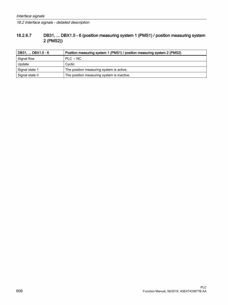
18.2.6.7 DB31, ... DBX1.5 - 6 (position measuring system 1 (PMS1) / position measuring system 2 (PMS2))
DB31, ... DBX1.5 - 6 Position measuring system 1 (PMS1) / position measuring system 2 (PMS2)Signal flow PLC → NCUpdate CyclicSignal state 1 The position measuring system is active.Signal state 0 The position measuring system is inactive.
Interface signals18.2 Interface signals - detailed description
PLC606 Function Manual, 06/2019, A5E47433877B AA

DB31, ... DBX1.5 - 6 Position measuring system 1 (PMS1) / position measuring system 2 (PMS2)Additional information Bit 6
(PMS 2)Bit 5
(PMS 1)Effect
0 1 Position measuring system 1 is active:● Position control of the machine axis via position measuring system 1.● Monitoring functions (measuring system, standstill, clamping
monitoring, contour deviation, etc.) of the machine axis via position measuring system 1.
● If position measuring system 2 exists (MD30200 $MA_NUM_ENCS == 2), its actual position value is acquired, but not monitored by any of these functions.
1 0 Position measuring system 2 is active:● Position control of the machine axis via position measuring system 2.● Monitoring functions (measuring system, standstill, clamping
monitoring, contour deviation, etc.) of the machine axis via position measuring system 2.
● If position measuring system 1 exists (MD30200 $MA_NUM_ENCS == 2), its actual position value is acquired, but not monitored by any of these functions.
1 1 ● Position control of the machine axis via position measuring system 1.● If position measuring system 2 is available (MD30200
$MA_NUM_ENCS == 2), its actual position value is also acquired.0 0 Position measuring systems 1 and 2 are inactive ("parking" of the ma‐
chine axis):● There is no actual value acquisition.● The monitoring of the position measuring system has been
deactivated.● The following interface signals are reset:
– DB31, ... DBX60.4 / 5 == 0 (referenced/synchronized, encoder 1/2)
– DB31, ... DBX61.5 (position controller active)– DB31, ... DBX61.6 (speed controller active)– DB31, ... DBX61.7 (current controller active)
Notes● If the interface signal of the active position measuring system is reset for a traversing axis,
the axis is stopped with a ramp stop without the controller enable being cancelled internally.
● If a speed-controlled spindle does not have a position measuring system, the "Controller enable" interface signal must be set:DB31, ... DBX2.1 == 1 (controller enable)
● After deactivation of the "parking" state, incremental position measuring systems have to be referenced to achieve the "referenced" encoder status.
● If the "parking" state is active, the following interface signal is ignored at NC start for this axis:DB31, ... DBX60.4 / 5 (referenced/synchronized 1/ 2).
Application examples
Interface signals18.2 Interface signals - detailed description
PLCFunction Manual, 06/2019, A5E47433877B AA 607

DB31, ... DBX1.5 - 6 Position measuring system 1 (PMS1) / position measuring system 2 (PMS2)1. Switching over from position measuring system 1 to positioning measuring system 2 (and
vice versa).If the axis was referenced in both position measuring systems and the limit frequency of the used measured value encoder has not been exceeded in the meantime, i.e.DB31, ... DBX60.4 and 60.5 == 1 (referenced/synchronized 1/2), a new reference point approach is not required after the switchover.On switchover, the current difference between position measuring system 1 and 2 is traversed immediately.A tolerance band in which the deviation between the two actual values may lie at the switchover can be specified in the following machine data:MD36500 $MA_ENC_CHANGE_TOL (maximum tolerance for actual position value switchover)If the actual value difference is greater than the tolerance, switchover is not performed and alarm 25100 "Measuring system switchover not possible" is displayed.
2. Machine axis is parked:The position measuring system monitoring is switched off when the measured value encoder is removed.
3. Switch off position measuring system:When the position measuring system 1 or 2 is switched off, the associated interface signal is reset:DB31, ... DBX60.4/5 (referenced/synchronized 1/2)
4. Reference point approach:Reference point approach of the axis is executed with the selected position measuring system. Every position measuring system must be referenced separately.
Corresponds to DB31, ... DBX60.4 / .5 (referenced/synchronized 1/2)DB31, ... DBX61.6 (speed controller active)DB31, ... DBX2.1 (controller enable)MD36500 $MA_ENC_CHANGE_TOL (max. tolerance on actual position value switchover)MD30200 $MA_NUM_ENCS (number of encoders)
Additional references Function Manual, Basic Functions; Velocities, Setpoint / Actual Value Systems, Closed-Loop Control (G2)
18.2.6.8 DB31, ... DBX1.7 (override active)
DB31, ... DBX1.7 Override activeSignal flow PLC → NCUpdate CyclicSignal state 1 Feedrate/spindle override is active.Signal state 0 Feedrate/spindle override is not active.
Interface signals18.2 Interface signals - detailed description
PLC608 Function Manual, 06/2019, A5E47433877B AA

DB31, ... DBX1.7 Override activeAdditional information The feedrate override factor (DB31, ... DBB0) specified by the NC/PLC interface is activated
with the interface signal.If the feedrate/spindle override is not active, then independent of the actual switch position, a value of 1.0 ≙ 100 % is used as override factor in the control. The first switch position is an exception. Depending on the selected coding, for the first switch position the following factor applies:● Binary coding: Override factor = 0● Gray coding: Override factor = MD12030 $MN_OVR_FACTOR_FEEDRATE[ 0 ]
Corresponds to MD12000 $MN_OVR_AX_IS_GRAY_CODE (axis-specific feedrate override switch Gray-co‐ded)MD12030 $MN_OVR_FACTOR_FEEDRATE (evaluation of the path feedrate override switch)MD12100 $MN_OVR_FACTOR_LIMIT_BIN (limit for binary coded override switch)
Additional references Basic Functions Function Manual; Section "V1: Feedrates" > "Feedrate control" > "Feedrate override from the machine control panel"
18.2.6.9 DB31, ... DBX2.0 (software cams: activation)
DB31, ... DBX2.0 Software cams: ActivationSignal flow PLC → NCUpdate CyclicSignal state 1 A request has been made to activate the output of the minus and plus cam signals of an axis
to the PLC interface.Signal state 0 A request has not been made to activate the output of the minus and plus cam signals of an
axis to the PLC interface.Corresponds with DB10 DBX110.0 - 113.7 (software cams: minus cam signal 1 to 32)
DB10 DBX114.0 - 117.7 (software cams: plus cam signal 1 to 32)DB31, ... DBX62.0 (software cams active)
Additional references Function Manual, Extended Functions; Chapter "N3: software cams, position switching sig‐nals"
18.2.6.10 DB31, ... DBX2.1 (controller enable)
DB31, ... DBX2.1 Controller enableSignal flow PLC → NCUpdate Cyclic
Interface signals18.2 Interface signals - detailed description
PLCFunction Manual, 06/2019, A5E47433877B AA 609

DB31, ... DBX2.1 Controller enableSignal state 1 Controller is enabled.
The position control loop is closed and the axis/spindle is in closed-loop control.Feedback:DB31, ... DBX61.5 = 1 (position controller active)If the axis/spindle was referenced before resetting the interface signal, the axis/spindle does not have to be re-referenced after the interface signal is set again. Supplementary condition: The limit frequency of the active measuring system must not be exceeded in the meantime.NoteIf the axis/spindle was moved from its position during the time in which the controller enable was not set, the behavior when the controller enable is set depends on the interface signal "follow-up mode":● DB31, ... DBX1.4 == 1 (follow-up mode)
Position control is performed at the current position● DB31, ... DBX1.4 == 0 (follow-up mode)
Position control is performed at the last position before the controller enable is resetSignal state 0 Controller is not enabled.
The behavior when the "controller enable" is removed depends on whether the axis/spindle is stationary or traversing at this time:● Axis/spindle stationary:
– The position control loop of the axis is opened.– For DB31, ... DBX1.4 == 1 (follow-up mode) ⇒ position setpoint = actual position value– The controller enable on the drive is reset– The following interface signals are reset:
DB31, ... DBX61.5 = 0 (position controller active)DB31, ... DBX61.6 = 0 (speed controller active)DB31, ... DBX61.7 = 0 (current controller active)
● Axis/spindle traverses– The axis is stopped with rapid stop.– Alarm 21612 "Controller enable VDI signal reset during motion".– The position control loop of the axis/spindle is opened.– Independent of the interface signal DB31, ... DBX1.4 (follow-up mode), the position
setpoint is corrected at the end of the braking operation (position setpoint = actual position value) and the feedback signal DB31, ... DBX61.3 = 1 (follow-up mode) is set.
– The following interface signals are reset:DB31, ... DBX61.5 (position controller active)DB31, ... DBX61.6 (speed controller active)DB31, ... DBX61.7 (current controller active)
NoteThe current set position is retained in the control when "Controller enable" is reset and "Follow-up mode" (DB31, ... DBX1.4 == 0) is not set. If the axis is moved in this state, e.g. manually, the difference between the set position and the actual position increases constantly (following error). The following error is suddenly corrected to zero when the "Controller enable" is set (speed setpoint jump).
Interface signals18.2 Interface signals - detailed description
PLC610 Function Manual, 06/2019, A5E47433877B AA

DB31, ... DBX2.1 Controller enableAdditional information Mechanical clamping of an axis
If the axis is positioned at the clamping position, the clamping mechanism is closed. The controller enable is then reset. Otherwise, the position controller would constantly work against the clamping, if the axis was moved mechanically from its specified position during the clamping operation.When the clamping is removed, the controller enable is set first and then the mechanical clamping is released.Note● Travel request for an axis/spindle without controller enable:
– The axis/spindle is not traversed– The travel command is output to the interface– As long as the travel request is present, the axis/spindle is traversed immediately when
the controller enable is set.● When the controller enable is reset for a traversing geometry axis, this always results in a
contour violation.Corresponds with DB31, ... DBX61.3 (follow-up active)
DB31, ... DBX1.4 (follow-up mode)DB31, ... DBX61.5 (position controller active)DB31, ... DBX61.6 (speed controller active)DB31, ... DBX61.7 (current controller active)MD36620 $MA_SERVO_DISABLE_DELAY_TIME (OFF delay of the controller enable)MD36610 $MA_AX_EMERGENCY_STOP_TIME (braking ramp time when errors occur)
18.2.6.11 DB31, ... DBX2.2 (spindle reset/delete distance to go)
DB31, ... DBX2.2 Delete distance-to-go/spindle resetSignal flow PLC → NCUpdate CyclicEdge change 0 → 1 Axis: "Delete-distance-to-go" is requested.
Spindle: Reset is requestedEdge change 1 → 0 No effect.
Interface signals18.2 Interface signals - detailed description
PLCFunction Manual, 06/2019, A5E47433877B AA 611

DB31, ... DBX2.2 Delete distance-to-go/spindle resetAdditional information Axis: Delete distance-to-go
● AUTOMATIC and MDI modesThe interface signal is only active if the axis is traversed as positioning axis. A positioning axis is decelerated to standstill along its brake characteristic. The distance-to-go of the axis is deleted.
● JOG modeThe axis is braked down to standstill alone its deceleration characteristic and then a possible delete distance to go is a deleted.
NoteAfter the delete distance to go, in an NC program, the following block is prepared again with the actual axis position. As a consequence, a different contour is traversed along than pro‐grammed in the NC program. Traversing to absolute position G90 in the block after "Delete distance-to-go" at least allows the programmed position is approached. When traversing using incremental dimension G91, then the programmed position would not be approached.Spindle: reset● Control mode:
– The spindle is stopped– The NC program is again executed– The spindle continues to rotate with the next M and S value programmed in the NC
program.● Oscillation mode:
– Oscillation is interrupted– The axes continue to traverse– The NC program continues with the actual gear stage– The spindle continues to rotate with the next M and S value programmed in the NC
program. The speed obtained from these values (actual S value and the last active gear stage) could be too high. In this case, the interface signal is set.DB31, ... DBX83.1
● Positioning mode: The spindle is stopped● Axis mode: The spindle is stoppedNoteThe response for a spindle reset is independent of the setting in machine data:MD35040 $MA_SPIND_ACTIVE_AFTER_RESETDwell time (G4): Delete distance-to-goDuring a block with dwell time (G4), the interface signal has no influence on the time that elapses.
Corresponds with DB21, ... DBX6.2 (delete distance-to-go)DB31, ... DBX83.1 (programmed speed too high)MD35040 $MA_SPIND_ACTIVE_AFTER_RESET (own spindle reset)
Additional references Basic Functions Function Manual; Chapter "S1: spindles"Function Manual, Extended Functions; Chapter "P2: positioning axes"
Interface signals18.2 Interface signals - detailed description
PLC612 Function Manual, 06/2019, A5E47433877B AA

18.2.6.12 DB31, ... DBX2.3 (clamping in progress)
DB31, ... DBX2.3 Clamping in progressSignal flow PLC → NCUpdate CyclicSignal state 1 Clamping in progress.
The clamping monitoring is active.Signal state 0 Clamping completed.
Standstill monitoring is active.Corresponds with MD36050 $MA_CLAMP_POS_TOL (clamping tolerance)
18.2.6.13 DB31, ... DBX2.4 - 7 (reference point value 1 - 4)
DB31, ... DBX2.4 - 7 Reference point value 1-4Signal flow PLC → NCUpdate CyclicAdditional information When the reference cam is reached, the NC is signaled by the interface which coded refer‐
ence cam has been approached.Actual value = MD34100 $MA_REFP_SET_POS [ <reference point value x> ]
Bit 7 Bit 6 Bit 5 Bit 4 Meaning0 0 0 0 Reference point value 10 0 0 1 Reference point value 10 0 1 0 Reference point value 20 1 0 0 Reference point value 31 0 0 0 Reference point value 4
Notes● The interface signal must remain set until the reference point is reached or until a new
coded reference cam is approached.● If the machine axis has reached the reference point, and noreference point value has been
selected, then reference point value 1 is used.● For length measuring systems with distance-coded reference marks, the interface signal
is irrelevant.Application exampleOn a machine tool with large traversing paths, up to four coded reference cams can be distributed over the distance traveled by the axis; up to four different reference points ap‐proached. This allows the traversing time when referencing to be shortened.
Corresponds with MD34100 $MA_REFP_SET_POS (reference point value)Additional references Basic Functions Function Manual; Chapter "R1: referencing"
Interface signals18.2 Interface signals - detailed description
PLCFunction Manual, 06/2019, A5E47433877B AA 613
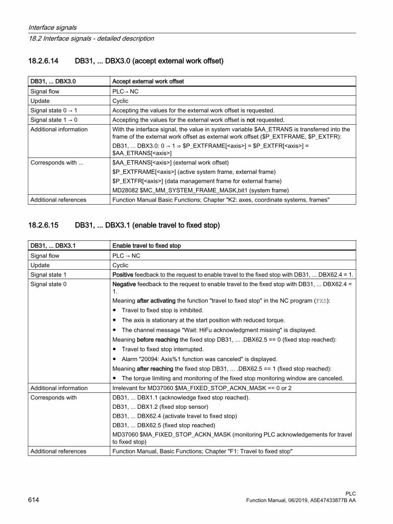
18.2.6.14 DB31, ... DBX3.0 (accept external work offset)
DB31, ... DBX3.0 Accept external work offsetSignal flow PLC→ NCUpdate CyclicSignal state 0 → 1 Accepting the values for the external work offset is requested.Signal state 1 → 0 Accepting the values for the external work offset is not requested.Additional information With the interface signal, the value in system variable $AA_ETRANS is transferred into the
frame of the external work offset as external work offset ($P_EXTFRAME, $P_EXTFR):DB31, ... DBX3.0: 0 → 1 ⇒ $P_EXTFRAME[<axis>] = $P_EXTFR[<axis>] = $AA_ETRANS[<axis>]
Corresponds with ... $AA_ETRANS[<axis>] (external work offset)$P_EXTFRAME[<axis>] (active system frame, external frame)$P_EXTFR[<axis>] (data management frame for external frame)MD28082 $MC_MM_SYSTEM_FRAME_MASK,bit1 (system frame)
Additional references Function Manual Basic Functions; Chapter "K2: axes, coordinate systems, frames"
18.2.6.15 DB31, ... DBX3.1 (enable travel to fixed stop)
DB31, ... DBX3.1 Enable travel to fixed stopSignal flow PLC → NCUpdate CyclicSignal state 1 Positive feedback to the request to enable travel to the fixed stop with DB31, ... DBX62.4 = 1.Signal state 0 Negative feedback to the request to enable travel to the fixed stop with DB31, ... DBX62.4 =
1.Meaning after activating the function "travel to fixed stop" in the NC program (FXS):● Travel to fixed stop is inhibited.● The axis is stationary at the start position with reduced torque.● The channel message "Wait: HiFu acknowledgment missing" is displayed.Meaning before reaching the fixed stop DB31, ... .DBX62.5 == 0 (fixed stop reached):● Travel to fixed stop interrupted.● Alarm "20094: Axis%1 function was canceled" is displayed.Meaning after reaching the fixed stop DB31, ... .DBX62.5 == 1 (fixed stop reached):● The torque limiting and monitoring of the fixed stop monitoring window are canceled.
Additional information Irrelevant for MD37060 $MA_FIXED_STOP_ACKN_MASK == 0 or 2Corresponds with DB31, ... DBX1.1 (acknowledge fixed stop reached).
DB31, ... DBX1.2 (fixed stop sensor)DB31, ... DBX62.4 (activate travel to fixed stop)DB31, ... DBX62.5 (fixed stop reached)MD37060 $MA_FIXED_STOP_ACKN_MASK (monitoring PLC acknowledgements for travel to fixed stop)
Additional references Function Manual, Basic Functions; Chapter "F1: Travel to fixed stop"
Interface signals18.2 Interface signals - detailed description
PLC614 Function Manual, 06/2019, A5E47433877B AA

18.2.6.16 DB31, ... DBX3.2 - 5 (activate fixed feedrate 1 - 4, machine axes)
DB 31, ... DBX3.2 - 5 Activate fixed feedrate 1 - 4, machine axesSignal flow PLC → NCUpdate CyclicAdditional information With the interface signals, in the JOG mode, the fixed feedrate - parameterized using machine
data - is activated.Bit 5 Bit 4 Bit 3 Bit 2 Meaning
0 0 0 0 Fixed feedrate not selected0 0 0 1 Fixed feedrate 10 0 1 0 Fixed feedrate 20 1 0 0 Fixed feedrate 31 0 0 0 Fixed feedrate 4
Instead of the parameterized JOG velocity/ JOG rapid traverse velocity (MD... ...JOG_VE‐LO_...), the axis is traversed with the selected fixed feedrate. The traversing direction is specified via the interface signal:DB31, ... DBX6 / 7 (traversing keys, minus/plus)The fixed feedrates are parameterized using the following machine data:● Linear axes: MD12202 $MN_PERMANENT_FEED● Rotary axes: MD12204 $MN_PERMANENT_ROT_AX_FEEDNotes● The fixed feedrate is not used for:
– Spindles– Positioning axes– Tapping
● The fixed feedrate is always interpreted as linear feedrate. Switchover to linear feedrate is performed internally in the control system also when revolutional feedrate is active.
Corresponds with MD12200 $MN_RUN_OVERRIDE_0 (traversing behavior with override 0)MD12202 $MN_PERMANENT_FEED (fixed feedrates for linear axes)MD12204 $MN_PERMANENT_ROT_AX_FEED (fixed feedrates for rotary axes)MD21150 $MC_JOG_VELO_RAPID_ORI (conventional rapid traverse for orientation axes)MD21155 $MC_JOG_VELO_ORI (conventional velocity for orientation axes)MD21160 $MC_JOG_VELO_RAPID_GEO (conventional rapid traverse for geometry axes) MD21165 $MC_JOG_VELO_GEO (conventional velocity for geometry axes)MD32010 $MA_JOG_VELO_RAPID (conventional rapid traverse)MD32020 $MA_JOG_VELO (conventional axis velocity)
Additional references Function Manual, Basic Functions; Chapter "V1: Feedrates" > "Feedrate control" > "Fixed feedrate values "
Interface signals18.2 Interface signals - detailed description
PLCFunction Manual, 06/2019, A5E47433877B AA 615

18.2.6.17 DB31, ... DBX3.6 (velocity/spindle speed limiting)
DB31, ... DBX3.6 Velocity/spindle speed limitationSignal flow PLC → NCUpdate CyclicSignal state 1 The velocity/spindle speed limiting is active.Signal state 0 The velocity/spindle speed limiting is not active.Additional information The control limits the velocity/spindle speed to the parameterized limit value:
MD35160 $MA_SPIND_EXTERN_VELO_LIMITCorresponds with MD35100 $MA_SPIND_VELO_LIMIT (maximum spindle speed)
MD35160 $MA_SPIND_EXTERN_VELO_LIMIT (spindle speed limiting from the PLC)SD43220 $SA_SPIND_MAX_VELO_G26 (programmable upper spindle speed limitation for G26)SD43230 $SA_SPIND_MAX_VELO_LIMS (spindle speed limitation for G96/G961/G97)
18.2.6.18 DB31, ... DBX4.0 - 2 (activate handwheel)
DB31, ... DBX4.0 - 2 Activate handwheelSignal flow PLC → NCUpdate CyclicAdditional information The interface can be interpreted either bit or binary-coded. The definition is realized using
machine data MD11324.Bit coded: maximum 3 handwheels Bit 2 Bit 1 Bit 0 Number of the assigned handwheel
0 0 0 No handwheel assignment0 0 1 10 1 0 21 0 0 3
Binary coded: maximum 6 handwheels Bit 2 Bit 1 Bit 0 Number of the assigned handwheel
0 0 0 No handwheel assignment0 0 1 10 1 0 20 1 1 31 0 0 41 0 1 51 1 0 6
NoteAt any one time, the machine axis can only be assigned to one handwheel. If, for bit coding, several interface signals are set simultaneously, then the following priority applies: "Hand‐wheel 1" before "Handwheel 2" before "Handwheel 3".
Interface signals18.2 Interface signals - detailed description
PLC616 Function Manual, 06/2019, A5E47433877B AA

DB31, ... DBX4.0 - 2 Activate handwheelCorresponds with DB31, ... DBX64.0 - 2 (handwheel active)
MD11324 $MN_HANDWH_VDI_REPRESENTATION (representation of the handwheel num‐ber at the VDI interface)
Additional references Function Manual, Extended Functions; Chapter "H1: manual and handwheel travel"
18.2.6.19 DB31, ... DBX4.3 (feedrate/spindle stop, axis-specific)
DB31, ... DBX4.3 Feedrate/spindle stop, axis-specificSignal flow PLC → NCUpdate CyclicSignal state 1 Feedrate/spindle stop is active.Signal state 0 Feedrate/spindle stop is not active.
Interface signals18.2 Interface signals - detailed description
PLCFunction Manual, 06/2019, A5E47433877B AA 617

DB31, ... DBX4.3 Feedrate/spindle stop, axis-specificAdditional information Axis
● If the interface signal is set while traversing the axis, then the axis is braked down to standstill along its braking characteristic. If the axis is in an interpolatory relationship with other axes, these are also braked.
● After the interface signal has been reset, traversing motion that was stopped is continued.● The position control is retained and the following error is eliminated.● If the interface signal is set, and a request is issued to traverse, then the axis is not
traversed. However, the traverse request is kept. When the interface signal is reset, the traverse request is immediately executed, i.e. the axis is traversed.
● The interface signal is active in all modes. Thread cutting Effectiveness
G33, G34, G35 Effective (contour deviations occur)G331, G332 EffectiveG63 Effective
Spindle● If the interface signal is set while traversing the spindle, then the spindle is braked down
to standstill along its braking characteristic. If the spindle is in an interpolatory relationship with other spindles, these are also braked.
● After the interface signal has been reset, traversing motion that was stopped is continued.● During positioning, the position control is retained and the following error is eliminated.● If the interface signal is set, and a request is issued to move during positioning operation,
then the spindle is not moved. However, the traverse request is kept. When the interface signal is reset, the traverse request is immediately executed, i.e. the spindle is moved.
● The interface signal is active in all modes.● The interface signal is not active during tapping (G331, G332). Thread cutting Effectiveness
G33, G34, G35 Effective (contour deviations can occur de‐pending on the dynamic performance that has been parameterized)
G331, G332 Not effectiveG63 Effective
NoteThe interface signal is not active when "Axis/spindle inhibit" (DB31, ... DBX1.3 == 1) is active.
Corresponds with DB31, ... DBX1.3 (axis/spindle disable)Additional references Function Manual, Basic Functions; Chapter "V1: Feedrates" > "Feedrate control" > "Feedrate
disable and feedrate/spindle stop"
18.2.6.20 DB31, ... DBX4.4 (traversing key disable)
DB31, ... DBX4.4 Traversing key lockSignal flow PLC → NCUpdate CyclicSignal state 1 The "Plus" and "Minus" traversing keys are locked.
Interface signals18.2 Interface signals - detailed description
PLC618 Function Manual, 06/2019, A5E47433877B AA

DB31, ... DBX4.4 Traversing key lockSignal state 0 The "Plus" and "Minus" traversing keys are enabled.Additional information Note
If the traversing key disable is activated while traversing, the axis is stopped.Corresponds with DB31, ... DBX4.6 - 7 (traversing keys "Plus" / "Minus")Additional references Function Manual, Extended Functions; Chapter "H1: manual and handwheel travel"
18.2.6.21 DB31, ... DBX4.5 (rapid traverse override)
DB31, ... DBX4.5 Rapid traverse overrideSignal flow PLC → NCUpdate CyclicSignal state 1 When manually traversing the machine axis using the traversing keys, when the interface
signal is set, rapid traverse velocity becomes active (MD32010). Signal state 0 When manually traversing the machine axis using the traversing keys, the entered JOG
velocity becomes active (SD41110 or MD32020).Additional information The signal is only active for continuous or incremental manual traversing in the JOG mode.
The signal is irrelevant:● for reference point approach (JOG mode)● in the AUTOMATIC and MDI modesThe rapid traverse velocity can be influenced using the rapid traverse override switch.
Corresponds with DB31, ... DBX4.6 - 7 (traversing keys "Plus" / "Minus")SD41110 $SN_JOG_SET_VELO (axis velocity for JOG)MD32010 $MA_JOG_VELO_RAPID (conventional rapid traverse)MD32020 $MA_JOG_VELO (conventional axis velocity)
Additional references Function Manual, Extended Functions; Chapter "H1: manual and handwheel travel"
18.2.6.22 DB31, ... DBX4.6 - 7 ("Plus" / "Minus" traversing keys)
DB31, ... DBX4.6 - 7 Traversing keys "Plus" / "Minus"Signal flow PLC → NCUpdate CyclicSignal state 1 A request has been made to traverse the machine axis using the traversing key in the positive/
negative axis direction.Signal state 0 A request has not been made to traverse the machine axis using the traversing key in the
positive/negative axis direction.
Interface signals18.2 Interface signals - detailed description
PLCFunction Manual, 06/2019, A5E47433877B AA 619

DB31, ... DBX4.6 - 7 Traversing keys "Plus" / "Minus"Additional information There is a request signal for every traversing key and/or axis direction:
Bit 6 Traversing key "Minus" (for traversing in the negative axis direction)Bit 7 Traversing key "Plus" (for traversing in the positive axis direction)
Depending on the active machine function, as well as the settings for jog and continuous operation (SD41050 and MD11300), different responses are initiated when the signal changes:1. Continuous manual travel in the jog mode
The machine axis traverses in the direction concerned to the active limit switch as long as the interface signal is set to 1.
2. Continuous manual travel in continuous operationOn the first edge change 0 →1 the machine axis starts to traverse in the relevant direction. This traversing movement still continues when the edge changes from 1 → 0. Any new signal edge change 0 → 1 (same traversing direction!) stops the traversing movement.
3. Incremental manual travel in the jog modeWith signal 1 the machine axis starts to traverse at the set increment. If the signal changes to the 0 state before the increment is traversed, then traversing is interrupted. When the signal state changes to 1 again, traversing is continued. The axis can be stopped and started several times as described above until it has traversed the complete increment.
4. Incremental manual travel in continuous operationAt the first edge change 0 → 1, the machine axis starts to traverse at the set increment. If another edge change 0 → 1 is performed with the same traverse signal before the geometry axis has traversed the increment, the traversing movement will be cancelled. The increment is no longer traversed to the end.
Note● The interface signal is irrelevant in operating modes:
– AUTOMATIC – MDI
● If both traversing signals ("plus" and "minus") are set at the same time there is no traversing or the current traversing is aborted.
● Traversing by means of the traversing keys can be locked via DB31, ... DBX4.4 (traversing key disable).
Corresponds with DB31, ... DBX4.4 (traversing key disable)DB31, ... DBX64.6 - 7 ("Plus" and "Minus" traversing command)MD11300 $MN_JOG_INC_MODE_LEVELTRIGGRD (INC and REF in jog mode)SD41050 $SN_JOG_CONT_MODE_LEVELTRIGGRD (jog/continuous operation for JOG, continuous)
Additional references Function Manual, Extended Functions; Chapter "H1: manual and handwheel travel"
18.2.6.23 DB31, ... DBX5.0 - 6 (machine function request)
DB31, ... DBX5.0 - 6 Machine function requestSignal flow PLC → NCUpdate CyclicSignal state 1 The machine function to manually traverse the machine axis has been requested.
Interface signals18.2 Interface signals - detailed description
PLC620 Function Manual, 06/2019, A5E47433877B AA

DB31, ... DBX5.0 - 6 Machine function requestSignal state 0 The machine function to manually traverse the machine axis has not been requested.Additional information There is a request signal for every machine function to manually traverse the machine axis in
the JOG mode.Bit 0 INC1Bit 1 INC10Bit 2 INC100Bit 3 INC1000Bit 4 INC10000Bit 5 INCvarBit 6 Continuous manual travel
Incremental manual travelIn addition to five fixed increment sizes (default setting in MD11330: INC1, INC10, INC100, INC1000 and INC10000), a variable increment size (INCvar) that can be set via the setting data SD41010 is also available. The distance evaluation of one increment for fixed and vari‐able increment sizes is performed via the axis-specific machine data MD31090.When pressing the "Plus" or "Minus" traversing key, or by rotating the electronic handwheel, the axis starts to traverse in the appropriate direction, corresponding to the number of incre‐ments of the active machine function.Continuous manual travelFor continuous manual travel, the plus and minus traversing keys are selected to move the axis continuously and the appropriate direction. Notes● If several requests are set simultaneously, no machine function becomes active.● If an axis is currently being traversed via a machine function, the movement is aborted
through deselection or change of the machine function.Corresponds with DB31, ... DBX65.0 - 65.6 (active machine function)
MD11320 $MN_HANDWH_IMP_PER_LATCH (handwheel pulses per detent position)MD11330 $MN_JOG_INCR_SIZE_TAB (increment size for INC/handwheel)MD31090 $MA_JOG_INCR_WEIGHT (evaluation of an increment for INC/handwheel)SD41010 $SN_JOG_VAR_INCR_SIZE (size of the variable increment for JOG)
Additional references Function Manual, Extended Functions; Chapter "H1: manual and handwheel travel"
18.2.6.24 DB31, ... DBX7.0 (invert handwheel direction of rotation)
DB31, ... DBX7.0 Invert handwheel direction of rotationSignal flow PLC → NCUpdate CyclicSignal state 1 A request has been made to invert the direction of rotation of the handwheel assigned to the
machine axis.Signal state 0 A request has not been made to invert the direction of rotation of the handwheel assigned to
the machine axis.
Interface signals18.2 Interface signals - detailed description
PLCFunction Manual, 06/2019, A5E47433877B AA 621

DB31, ... DBX7.0 Invert handwheel direction of rotationAdditional information Note
It is only permissible to change the interface signal when the machine axis is at a standstill.Application examples● The direction of movement of the handwheel does not match the expected direction of the
axis.● A handwheel is assigned to several axes with different orientations.
Corresponds with DB31, ... DBX67.0 (handwheel direction of rotation inversion active)Additional references Function Manual, Extended Functions; Chapter "H1: manual and handwheel travel"
18.2.6.25 DB31, ... DBB8 (request axis/spindle replacement)
DB31, ... DBB8 Axis/spindle exchange requestSignal flow PLC → NCUpdate CyclicEdge change 0 → 1 Request from PLC, switchover axisEdge change 1 → 0 Acknowledged by the NCAdditional information From the PLC user program, via DBB8 an axis/spindle exchange can be requested:
● From an NC channel to the PLC● From the PLC to an NC channel● From an NC channel to another NC channelBit Meaning0 ... 3 Name of the channel to which the axis/spindle is to be assigned (binary code).
Example:The axis should be assigned to channel 2.
Bit 3 Bit 2 Bit 1 Bit 0 Channel num‐ber
0 0 1 0 24 Request axis/spindle exchange
0 → 1 Request from PLC1 → 0 Acknowledged by the NC
5 -6 -7 Request "PLC axis"
Corresponds with DB31, ... DBB68 (Axis/spindle replacement)MD20070 $MC_AXCONF_MACHAX_USED (machine axis number valid in channel)MD30550 $MA_AXCONF_ASSIGN_MASTER_CHAN (initial setting of channel for axis re‐placement)
Additional references Function Manual, Extended Functions; Chapter "K10: Cross-channel axis interchange"
Interface signals18.2 Interface signals - detailed description
PLC622 Function Manual, 06/2019, A5E47433877B AA

18.2.6.26 DB31, ... DBX9.0 - (2 select: position controller parameter set)
DB31, ... DBX9.0 - 2 Selection: Position controller parameter setSignal flow PLC → NCUpdate Job-controlledAdditional information Bit 2 Bit 1 Bit 0 Parameter set
0 0 0 10 0 1 20 1 0 30 1 1 41 0 0 51 0 1 61 1 0 61 1 1 6
NoteSelecting a position controller parameter set is ignored, for:MD35590 $MA_PARAMSET_CHANGE_ENABLE == 0
Corresponds with DB31, ...DBX69.0, .1, ..2 (feedback signal: active position controller parameter set)Additional references SINUMERIK 840D sl Commissioning Manual, CNC Commissioning: NC, PLC, Drive; Section:
"NC commissioning"
18.2.6.27 DB31, ... DBX9.3 (parameter set definitions disabled by NC)
DB31, ... DBX9.3 Parameter set definitions disabled by NCSignal flow PLC → NCUpdate Job-controlledSignal state 1 The parameter set switchover is disabled.Signal state 0 The parameter set switchover is enabled.Corresponds with DB31, ... DBX9.0, .1, .2
18.2.6.28 DB31, ... DBX10.0 (REPOS delay)
DB31, ... DBX10.0 REPOS delaySignal flow PLC → NCUpdate CyclicSignal state 1 A REPOS delay is requested.
After a block search, a REPOS offset is applied for this axis. However it is not applied using the approach block, but rather using the next traversing block in which the axis is program‐med.
Signal state 0 A REPOS delay is not requested.After a block search, a REPOS offset is applied for this axis using the approach block.
Interface signals18.2 Interface signals - detailed description
PLCFunction Manual, 06/2019, A5E47433877B AA 623

DB31, ... DBX10.0 REPOS delayAdditional information Note
If the machine axes are involved on a path (DB31, ... DBX76.4 == 1 (path axis)), then the interface signal is not active.
Corresponds with DB21, ... DBX25.4 (REPOS mode activation)DB21, ... DBX31.0 - 2 (REPOS mode)DB21, ... DBX31.4 (REPOS mode change)DB31, ... DBX72.0 (REPOS delay)DB21, ... DBX319.0 (REPOS mode change acknowledgment)DB21, ... DBX319.1 - 3 (active REPOS mode)DB21, ... DBX319.5 (REPOS acknowledgment delay)DB31, ... DBX70.0 (REPOS offset)DB31, ... DBX70.1 (REPOS offset valid)DB31, ... DBX70.2 (REPOS delay acknowledgment)DB31, ... DBX76.4 (path axis)MD11470 $MN_REPOS_MODE_MASK (repositioning properties)
Additional references Basic Functions Function Manual; Chapter "K1: Mode group, channel, program mode, reset response" > "Block search type 5 (SERUPRO)" > "Repositioning to the contour (REPOS)"
18.2.6.29 DB31, ... DBX12.0 (hardware limit switch minus)
DB31, ... DBX12.0 Hardware limit switch minus:Signal flow PLC → NCUpdate CyclicSignal state 1 The hardware limit switch minus was activated.Signal state 0 The hardware limit switch minus was not activated.Additional information Alarm 21614 "Hardware limit switch -" is displayed, and the axis is stopped.Corresponds with MD36600 $MA_BRAKE_MODE_CHOICE (deceleration behavior when the hardware limit
switch responds)
18.2.6.30 DB31, ... DBX12.1 (hardware limit switch plus)
DB31, ... DBX12.1 Hardware limit switch plusSignal flow PLC → NCUpdate CyclicSignal state 1 Hardware limit switch plus was triggered.Signal state 0 Hardware limit switch plus was not triggered.Additional information Alarm 21614 "Hardware limit switch +" is displayed, and the axis is stopped.Corresponds with MD36600 $MA_BRAKE_MODE_CHOICE (deceleration behavior when the hardware limit
switch responds)
Interface signals18.2 Interface signals - detailed description
PLC624 Function Manual, 06/2019, A5E47433877B AA

18.2.6.31 DB31,... DBX12.2 (second software limit switch minus)
DB31, ... DBX12.2 Second software limit switch minusSignal flow PLC → NCUpdate CyclicSignal state 1 Second software limit switch minusSignal state 0 The second software limit switch minus was not triggered.Corresponds with MD36100 $MA_POS_LIMIT_MINUS (1st software limit switch minus)
MD36120 $MA_POS_LIMIT_MINUS2 (2nd software limit switch minus)
18.2.6.32 DB31, ... DBX12.3 (second software limit switch plus)
DB31, ... DBX12.3 Second software limit switch plusSignal flow PLC → NCUpdate CyclicSignal state 1 The second software limit switch plus was triggered.Signal state 0 The second software limit switch plus was not triggered.Corresponds with MD36110 $MA_POS_LIMIT_PLUS (1st software limit switch plus)
MD36130 $MA_POS_LIMIT_PLUS2 (2nd software limit switch plus)
18.2.6.33 DB31, ... DBX12.4 (modulo rotary axis: activate traversing range limits)
DB31, ... DBX12.4 Modulo rotary axis: activate traversing range limits Signal flow PLC → NCUpdate CyclicSignal state 1 Activate traversing range limits (software limit switch, working area limits) for modulo rotary
axes.Signal state 0 Deactivate traversing range limits for modulo rotary axes.Additional information Note
The signal is irrelevant if linear axes/rotary axes do not have modulo functionality.Application exampleMounted rotary axis with monitoring
Corresponds with DB31, ... DBX74.4 (modulo rotary axis: traversing range limits active)Additional references Function Manual, Extended Functions; Chapter "R2: rotary axes"
18.2.6.34 DB31, ... DBX12.7 (reference point approach deceleration)
DB31, ... DBX12.7 Deceleration of reference point approachSignal flow PLC → NCUpdate CyclicSignal state 1 The machine axis is positioned at the reference cam.
Interface signals18.2 Interface signals - detailed description
PLCFunction Manual, 06/2019, A5E47433877B AA 625

DB31, ... DBX12.7 Deceleration of reference point approachSignal state 0 The machine axis is positioned in front of the reference cam. Additional information Note
Using a suitable reference cam, which extends from the reference point to the end of the traversing range, it is recommended to ensure that before the reference point approach, the machine axis can be located in the range behind the reference cam.
Corresponds with DB31, ... DBX2.4 - 7 (reference point value 1 to 4)Additional references Basic Functions Function Manual; Chapter "R1: referencing"
18.2.6.35 DB31, ... DBX13.0 - 2 (JOG approach fixed point)
DB31, ... DBX13.0 - 2 JOG fixed point approachSignal flow PLC → NCUpdate CyclicAdditional information After selecting the "Approach fixed point in JOG" function, the PLC outputs the number of the
fixed point to be approached binary coded to the NC using DB31, ... DBX.0 - 2: Bit 2 Bit 1 Bit 0 Number of fixed point to be approached
0 0 0 -0 0 1 10 1 0 20 1 1 31 0 0 4
As soon as the function is active (see DB31, ... DBX75.0 - 2), then the selected machine axis can be traversed to the corresponding fixed point using either the traversing keys or the handwheel. The fixed points are defined using machine data MD30600.
Corresponds with DB31, ... DBX75.0 - 2 (JOG approach fixed point active)DB31, ... DBX75.3 - 5 (JOG approach fixed point reached)MD30600 $MA_FIX_POINT_POS[<n>] (fixed value positions of the axis)
Additional references Function Manual, Extended Functions; Chapter "H1: manual and handwheel travel"
18.2.6.36 DB31, ... DBX13.3 (JOG travel to position)
DB31, ... DBX13.3 JOG travel to positionSignal flow PLC → NCUpdate CyclicSignal state 1 The function "Position travel in JOG" is requested:Signal state 0 The function "Position travel in JOG" is not requested:
Interface signals18.2 Interface signals - detailed description
PLC626 Function Manual, 06/2019, A5E47433877B AA

DB31, ... DBX13.3 JOG travel to positionAdditional information As soon as the function is active (see DB31, ... DBX75.6), then using the traversing keys or
the handwheel, the selected machine axis can be traversed to the position specified with setting data SD43320.ApplicationThe function is used for machine tools that are exclusively operated manually, e.g. to ap‐proach drill-holes in precise increments.NoteThe following preconditions applying for the "Position travel in JOG" function: ● The function can only be activated in the JOG mode.
The function cannot be activated if the machine function JOG-REPOS or JOG-REF is active and in JOG in AUTOMATIC.
● The axis to be traversed must be referenced.● A kinematic transformation may not be active.● The axis to be traversed may not be a following axis of an active coupling.
Corresponds with DB31, ... DBX75.6 (JOG travel to position active)DB31, ... DBX75.7 (JOG position reached)SD43320 $SA_JOG_POSITION (JOG position)
Additional references Function Manual, Extended Functions; Chapter "H1: manual and handwheel travel"
18.2.6.37 DB31, ... DBX14.0 (suppress program test)
DB31, ... DBX14.0 Suppress program testSignal flow PLC → NCUpdate CyclicSignal state 1 Suppression of the program test (setpoint output locked) is requested.Signal state 0 Suppression of the program test (setpoint output locked) is not requested.Additional information If function "Program test" (PRT) is active in the channel to which the axis currently belongs,
the axis is traversed with internal axis disable. Setpoints are generated but they not output to the machine axes. Actual value = Setpoint. If the program test is suppressed for the axis, setpoints are output to the machine axis despite the function "program test" being active in the channel to which the axis currently belongs.Automatic transfer of the interface signalsThe HMI request signals DB21, ... DBX128.0 / .1 are only transferred from the basic PLC program to the PLC request signals DB21, ... DBX14.0 / .1 if FB1 parameter MMCToIF is set to TRUE. If the parameter is not set, the PLC request signals must be set by the PLC user program.
Corresponds with DB31, ... DBX14.1 (activate program test)DB31, ... DBX128.0 (suppress program test)DB31, ... DBX128.1 (activate program test)
Additional references Function Manual Extended Functions, Chapter "K5: Cross-channel program coordination" > "Channel-by-channel running-in"
Interface signals18.2 Interface signals - detailed description
PLCFunction Manual, 06/2019, A5E47433877B AA 627

18.2.6.38 DB31, ... DBX14.1 (activate program test)
DB31, ... DBX14.1 Activate program testSignal flow PLC → NCUpdate CyclicSignal state 1 Activation of the function "program test" (setpoint output locked) is requested.Signal state 0 Activation of the function "program test" (setpoint output locked) is not requested.Additional information If the function "program test" is active, the axis is traversed with internal axis disable. Setpoints
are generated but they not output to the machine axes. Actual value = Setpoint. Automatic transfer of the interface signalsThe HMI request signals DB21, ... DBX128.0 / .1 are only transferred from the basic PLC program to the PLC request signals DB21, ... DBX14.0 / .1 if FB1 parameter MMCToIF is set to TRUE. If the parameter is not set, the PLC request signals must be set by the PLC user program.
Corresponds with DB31, ... DBX14.0 (suppress program test)DB31, ... DBX128.0 (suppress program test)DB31, ... DBX128.1 (activate program test)
Additional references Function Manual Extended Functions, Chapter "K5: Cross-channel program coordination" > "Channel-by-channel running-in"
18.2.6.39 DB31, ... DBX16.0 - 2 (actual gear stage)
DB31, ... DBX16.0 - 2 Actual gear stageSignal flow PLC → NCUpdate Cyclic
Interface signals18.2 Interface signals - detailed description
PLC628 Function Manual, 06/2019, A5E47433877B AA

DB31, ... DBX16.0 - 2 Actual gear stageAdditional information If the new gear stage is selected at the machine, the PLC user program sets the following
interface signals as feedback signal to the NC:● DB31, ... DBX16.0 - 2 (actual gear stage)● DB31, ... DBX16.3 (gear stage has been changed)This signals the NC that the correct stage has been successfully selected. The associated parameter set becomes active in the NC.Bit 2 Bit 1 Bit 0 Parameter set
No.Meaning: Parameter set for
--- --- --- 0 Axis mode0 0 0 1 Gear stage 10 0 1 Gear stage 10 1 0 2 Gear stage 20 1 1 3 Gear stage 31 0 0 4 Gear stage 41 0 1 5 Gear stage 51 1 0 Gear stage 51 1 1 Gear stage 5
NoteIf the PLC user program signals back to the NC with a different actual gear stage than issued by the NC as the set gear stage requested by the PLC, the gear change is still considered to have been successfully completed and the actual gear stage that is signaled back is activated in the NC.
Corresponds with DB31, ... DBX16.3 (gear stage has been changed)DB31, ... DBX18.5 (oscillation speed)DB31, ... DBX82.0 - 2 (set gear stage)DB31, ... DBX82.3 (change over gear stage)
Additional references Basic Functions Function Manual; Chapter "S1: spindles"
18.2.6.40 DB31, ... DBX16.3 (gear stage has been changed)
DB31, ... DBX16.3 Gear is changed overSignal flow PLC → NCUpdate CyclicEdge change 0 → 1 Gear is changed overEdge change 1 → 0 No effect.
Interface signals18.2 Interface signals - detailed description
PLCFunction Manual, 06/2019, A5E47433877B AA 629

DB31, ... DBX16.3 Gear is changed overAdditional information If the new gear stage is selected at the machine, the PLC user program sets the following
interface signals as feedback signal to the NC:● DB31, ... DBX16.0 - 2 (actual gear stage)● DB31, ... DBX16.3 = 0 → 1 (gear stage has been changed)Feedback signal from the NC to the PLC: DB31, ... DBX82.3 = 0 (changeover gear stage)Feedback signal from the PLC to the NC: DB31, ... DBX16.3 = 0 (gear stage has been changed)This completes the gear stage change in the control system.Note● The interface signal is irrelevant for all spindle modes with the exception of the oscillation
mode.● If the PLC user program signals back to the NC with a different actual gear stage than
issued by the NC as the set gear stage requested by the PLC, the gear change is still considered to have been successfully completed and the actual gear stage that is signaled back is activated in the NC.
Corresponds with DB31, ... DBX16.0 - 2 (actual gear stage)DB31, ... DBX82.0 - 2 (set gear stage)DB31, ... DBX82.3 (change over gear stage)DB31, ... DBX18.5 (oscillation speed)
Additional references Basic Functions Function Manual; Chapter "S1: spindles"
18.2.6.41 DB31, ... DBX16.4 (resynchronize spindle, measuring system 1)
DB31, ... DBX16.4 Resynchronize spindle, measuring system 1Signal flow PLC → NCUpdate CyclicEdge change 0 → 1 There is an active request to synchronize measuring system 1 of the spindle.Edge change 1 → 0 No effect.Additional information Note
The interface signal is irrelevant for all spindle modes with the exception of the control mode.Corresponds with DB31, ... DBX60.4 (referenced / synchronized 1)
DB31, ... DBX60.5 (referenced / synchronized 2)Additional references Basic Functions Function Manual; Chapter "S1: spindles"
18.2.6.42 DB31, ... DBX16.5 (resynchronize spindle, measuring system 2)
DB31, ... DBX16.5 Resynchronize spindle, measuring system 2Signal flow PLC → NCUpdate CyclicEdge change 0 → 1 There is an active request to synchronize measuring system 2 of the spindle.Edge change 1 → 0 No effect.
Interface signals18.2 Interface signals - detailed description
PLC630 Function Manual, 06/2019, A5E47433877B AA

DB31, ... DBX16.5 Resynchronize spindle, measuring system 2Additional information Note
The interface signal is irrelevant for all spindle modes with the exception of the control mode.Corresponds with DB31, ... DBX60.4 (referenced / synchronized 1)
DB31, ... DBX60.5 (referenced / synchronized 2)Additional references Basic Functions Function Manual; Chapter "S1: spindles"
18.2.6.43 DB31, ... DBX16.7 (delete S value)
DB31, ... DBX16.7 Delete S valueSignal flow PLC → NCUpdate CyclicEdge change 0 → 1 There is an active request to delete the S value.Edge change 1 → 0 No effect.Additional information Control mode:
● The spindle is braked via its parameterized braking ramp down to standstill.Oscillation mode, axis mode, positioning mode:● Deleting the actual S value has no effect on the actual function. However, if the control
mode is selected again, a new S value must be programmed.Additional references Basic Functions Function Manual; Chapter "S1: spindles"
18.2.6.44 DB31, ... DBX17.4 (resynchronizing the spindle before positioning, measuring system 1)
DB31, ... DBX17.4 Resynchronizing the spindle before positioning, measuring system 1Signal flow PLC → NCUpdate CyclicEdge change 0 → 1 There is an active request to resynchronize measuring system 1 before positioning the spin‐
dle.Edge change 1 → 0 No effect.Additional information Note
The interface signal is irrelevant for all spindle modes with the exception of the positioning mode.
Corresponds with DB31, ... DBX60.4 (referenced/synchronized 1)Additional references Basic Functions Function Manual; Chapter "S1: spindles"
18.2.6.45 DB31, ... DBX17.5 (resynchronizing the spindle before positioning, measuring system 2)
DB31, ... DBX17.5 Resynchronizing the spindle before positioning, measuring system 2Signal flow PLC → NCUpdate CyclicEdge change 0 → 1 There is an active request to resynchronize measuring system 2 before positioning the spin‐
dle.
Interface signals18.2 Interface signals - detailed description
PLCFunction Manual, 06/2019, A5E47433877B AA 631

DB31, ... DBX17.5 Resynchronizing the spindle before positioning, measuring system 2Edge change 1 → 0 No effect.Additional information Note
The interface signal is irrelevant for all spindle modes with the exception of the positioning mode.
Corresponds with DB31, ... DBX60.2 (referenced/synchronized 2)Additional references Basic Functions Function Manual; Chapter "S1: spindles"
18.2.6.46 DB31, ... DBX17.6 (invert M3 / M4)
DB31, ... DBX17.6 Invert M3/M4Signal flow PLC → NCUpdate CyclicEdge change 0 → 1 There is an active request to invert the direction of rotation programmed with M3 / M4.Edge change 1 → 0 No effect.Additional information The direction of rotation of the spindle motor changes for the following functions:
● M3● M4● M5● SPOS/M19/SPOSA from the motion; not effective for SPOS/M19/SPOSA from zero speed
(stationary).Additional references Basic Functions Function Manual; Chapter "S1: spindles"
18.2.6.47 DB31, ... DBX18.4 (oscillation controlled by the PLC)
DB31, ... DBX18.4 Oscillation controlled by the PLCSignal flow PLC → NCUpdate CyclicEdge change 0 → 1 The "Oscillation of the machine axis controlled by the PLC user program" function is reques‐
ted.Edge change 1 → 0 The "Oscillation of the machine axis controlled by the PLC user program" function is not
requested.Additional information For the "Oscillation of the machine axis controlled by the PLC user program" function the
following system data must be set or parameterized.● DB31, ... DBX18.4 = 1 (oscillation controlled by the PLC)● DB31, ... DBX18.5 = 1 (oscillation speed)● MD35400 $MA_SPIND_OSCILL_DES_VELO = <oscillation speed>● MD35410 $MA_SPIND_OSCILL_ACCEL = <oscillation acceleration>● DB31, ... DBX18.6 = ... → 0 → 1 → 0 ... (set direction of rotation clockwise)● DB31, ... DBX18.7 = ... → 1 → 0 → 1 ... (set direction of rotation counterclockwise)The direction of rotation when starting and the traversing duration for each direction of rotation must be specified by the PLC user program.
Interface signals18.2 Interface signals - detailed description
PLC632 Function Manual, 06/2019, A5E47433877B AA
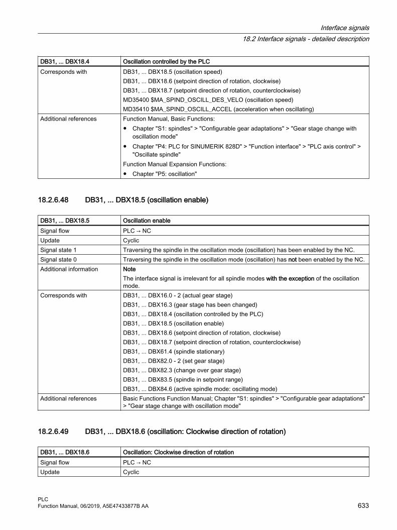
DB31, ... DBX18.4 Oscillation controlled by the PLCCorresponds with DB31, ... DBX18.5 (oscillation speed)
DB31, ... DBX18.6 (setpoint direction of rotation, clockwise)DB31, ... DBX18.7 (setpoint direction of rotation, counterclockwise)MD35400 $MA_SPIND_OSCILL_DES_VELO (oscillation speed)MD35410 $MA_SPIND_OSCILL_ACCEL (acceleration when oscillating)
Additional references Function Manual, Basic Functions:● Chapter "S1: spindles" > "Configurable gear adaptations" > "Gear stage change with
oscillation mode"● Chapter "P4: PLC for SINUMERIK 828D" > "Function interface" > "PLC axis control" >
"Oscillate spindle"Function Manual Expansion Functions:● Chapter "P5: oscillation"
18.2.6.48 DB31, ... DBX18.5 (oscillation enable)
DB31, ... DBX18.5 Oscillation enableSignal flow PLC → NCUpdate CyclicSignal state 1 Traversing the spindle in the oscillation mode (oscillation) has been enabled by the NC.Signal state 0 Traversing the spindle in the oscillation mode (oscillation) has not been enabled by the NC.Additional information Note
The interface signal is irrelevant for all spindle modes with the exception of the oscillation mode.
Corresponds with DB31, ... DBX16.0 - 2 (actual gear stage)DB31, ... DBX16.3 (gear stage has been changed)DB31, ... DBX18.4 (oscillation controlled by the PLC)DB31, ... DBX18.5 (oscillation enable)DB31, ... DBX18.6 (setpoint direction of rotation, clockwise)DB31, ... DBX18.7 (setpoint direction of rotation, counterclockwise)DB31, ... DBX61.4 (spindle stationary)DB31, ... DBX82.0 - 2 (set gear stage)DB31, ... DBX82.3 (change over gear stage)DB31, ... DBX83.5 (spindle in setpoint range)DB31, ... DBX84.6 (active spindle mode: oscillating mode)
Additional references Basic Functions Function Manual; Chapter "S1: spindles" > "Configurable gear adaptations" > "Gear stage change with oscillation mode"
18.2.6.49 DB31, ... DBX18.6 (oscillation: Clockwise direction of rotation)
DB31, ... DBX18.6 Oscillation: Clockwise direction of rotation Signal flow PLC → NCUpdate Cyclic
Interface signals18.2 Interface signals - detailed description
PLCFunction Manual, 06/2019, A5E47433877B AA 633

DB31, ... DBX18.6 Oscillation: Clockwise direction of rotation Signal state 1 Clockwise oscillation direction of rotation is requested.Signal state 0 Clockwise oscillation direction of rotation is not requested.Additional information Note
The interface signal is irrelevant for all spindle modes with the exception of the oscillation mode.
Corresponds to DB31, ... DBX16.0 - 2 (actual gear stage)DB31, ... DBX16.3 (gear stage has been changed)DB31, ... DBX18.4 (oscillation controlled by the PLC)DB31, ... DBX18.5 (oscillation enable)DB31, ... DBX18.7 (setpoint direction of rotation, counterclockwise)DB31, ... DBX61.4 (spindle stationary)DB31, ... DBX82.0 - 2 (set gear stage)DB31, ... DBX82.3 (change over gear stage)DB31, ... DBX83.5 (spindle in setpoint range)DB31, ... DBX84.6 (active spindle mode: Oscillation mode)
Additional references Basic Functions Function Manual; Section "S1: spindles" > "Configurable gear adaptations" > "Gear stage change with oscillation mode"
18.2.6.50 DB31, ... DBX18.7 (oscillation: Counterclockwise direction of rotation)
DB31, ... DBX18.7 Oscillation: Counterclockwise direction of rotation Signal flow PLC → NCUpdate CyclicSignal state 1 Counterclockwise oscillation direction of rotation is requested.Signal state 0 Counterclockwise oscillation direction of rotation is not requested.Additional information Note
The interface signal is irrelevant for all spindle modes with the exception of the oscillation mode.
Corresponds to DB31, ... DBX16.0 - 2 (actual gear stage)DB31, ... DBX16.3 (gear stage has been changed)DB31, ... DBX18.4 (oscillation controlled by the PLC)DB31, ... DBX18.5 (oscillation enable)DB31, ... DBX18.6 (setpoint direction of rotation, clockwise)DB31, ... DBX61.4 (spindle stationary)DB31, ... DBX82.0 - 2 (set gear stage)DB31, ... DBX82.3 (change over gear stage)DB31, ... DBX83.5 (spindle in setpoint range)DB31, ... DBX84.6 (active spindle mode: Oscillation mode)
Additional references Basic Functions Function Manual; Section "S1: spindles" > "Configurable gear adaptations" > "Gear stage change with oscillation mode"
Interface signals18.2 Interface signals - detailed description
PLC634 Function Manual, 06/2019, A5E47433877B AA

18.2.6.51 DB31, ... DBB19 (speed override, spindle-specific)
DB31, ... DBB19 Speed override, spindle-specificSignal flow PLC → NCUpdate Cyclic
Interface signals18.2 Interface signals - detailed description
PLCFunction Manual, 06/2019, A5E47433877B AA 635

DB31, ... DBB19 Speed override, spindle-specificAdditional information Binary/Gray coding
The override factors can be specified in the binary or Gray-coded format. The control must be informed of the used format via the following machine data:MD12060 $MN_OVR_SPIN_IS_GRAY_CODE = <Coding>Binary codingWith binary coding, the value in the interface corresponds to the override factor.
Binary code Decimal Override factor0000 0000 0 0.000000 0001 1 0.010000 0010 2 0.020000 0011 3 0.03000 0100 4 0.04
... ... ...0110 0100 100 1.00
... ... ...1100 1000 200 2.00
Gray codingThe Gray-coded values of the interface are assigned the override factors via the following machine data:MD12070 $MN_OVR_FACTOR_SPIND_SPEED[ <Switch position> - 1 ] = <Override factor>Switch position Gray code Override factor 1)
1 00001 0.502 00011 0.553 00010 0.604 00110 0.655 00111 0.706 00101 0.757 00100 0.808 01100 0.859 01101 0.9010 01111 0.9511 01110 1.0012 01010 1.0513 01011 1.1014 01001 1.1515 01000 1.2016 11000 1.2017 11001 1.2018 11011 1.2019 11010 1.2020 11110 1.2021 11111 1.2022 11101 1.20
Interface signals18.2 Interface signals - detailed description
PLC636 Function Manual, 06/2019, A5E47433877B AA

DB31, ... DBB19 Speed override, spindle-specific23 11100 1.2024 10100 1.2025 10101 1.2026 10111 1.2027 10110 1.2028 10010 1.2029 10011 1.2030 10001 1.2031 10000 1.20
Limitations● The active override factor is limited internally in the control to 2.00 or 200%.● The effective override factor is limited to 100% in the "oscillation mode" spindle mode.● The maximum possible override factor can be limited to a value less than 200% with the
following machine data:MD12100 $MN_OVR_FACTOR_LIMIT_BIN
Notes● The spindle-specific speed override is not effective with the following function when cutting
threads: G63● The spindle-specific speed override acts on the programmed values before other limits
(e.g. G26, LIMS...) take effect.Corresponds to MD12080 $MN_OVR_REFERENCE_IS_PROG_FEED (override reference velocity)
DB31, ... DBB0 (feedrate override, axis-specific)DB31, ... DBX1.7 (feedrate/speed override active)
Additional references Basic Functions Function Manual; Section "V1: Feedrates" > "Feedrate control" > "Feedrate override from the machine control panel"
1) Default values
18.2.6.52 DB31, ... DBX20.1 (ramp-function generator disable)
DB31, ... DBX20.1 Ramp-function generator disableSignal flow PLC → NCUpdate CyclicSignal state 1 A rapid stop with speed setpoint 0 is requested for the drive. The drive is stopped without a
ramp function (regenerative braking).Feedback for the triggering of the rapid stop in the drive is via:DB31, ... DBX92.1 == 1 (ramp-function generator disable active)
Signal state 0 No rapid stop with speed setpoint 0 is requested for the drive.Additional information Using drive parameters p0922 and p2038, a PROFIdrive telegram compatible with the "SI‐
MODRIVE 611 universal" interface mode must be set in the drive.
Interface signals18.2 Interface signals - detailed description
PLCFunction Manual, 06/2019, A5E47433877B AA 637

DB31, ... DBX20.1 Ramp-function generator disableCorresponds with DB31, ... DBX92.1 (ramp-function generator disable active)
Driver parameter p0922 (IF1 PROFIdrive PZD telegram selection)Drive parameter p2038 (IF1 PROFIdrive STW/ZSW interface mode)
Additional references NC: SINUMERIK 840D sl Commissioning Manual, CNC Commissioning: NC, PLC, DriveDrive: SINAMICS S120/S150 List Manual
18.2.6.53 DB31, ... DBX21.0 - 4 (motor/drive data set: selection)
DB31, ... DBX21.0 - 4 Motor/drive data set: SelectionSignal flow PLC → NCUpdate CyclicAdditional information The switchover to a new motor (MDS) and/or to drive data sets (DDS) is requested via the
interface:FormattingFormatting the request interface, i.e. which bits are used to address the motor data sets (MDS) – and which are used to address the drive data sets (DDS) is set via the formatting interface (DB31, …DBX130.0 - 4).Main spindle driveFor main spindle drives, the following classification applies:● MDS[ 0 ] → star operation● MDS[ 1 ] → delta operationSwitchover timeIn principle it is possible to switch over drive parameter sets at any time. However, as torque jumps can occur when switching over speed controller parameters and motor speed normal‐ization, parameters should only be switched over in stationary states, especially axis standstill.As soon as the request to switch over to another motor data set is identified, the pulses enable is reset.Application examples● Main spindle drive
For example, it is possible to switch between operating mode 1 (star operation) and operating mode 2 (delta operation) for a main spindle drive (MSD) by switching over the motor data set.
● Drive parameter setIt may be necessary to switch over the drive parameter set, for:– Gear stage change– Changing the measuring circuit
Corresponds with DB31, ... DBX93.0 - 4 (motor/drive data set: display)DB31, …DBX130.0 - 4 (motor/drive data set: formatting)DB31, ... DBX21.5 (motor has been selected)
Additional references ● Function Manual, Basic Functions, Chapter "A2: Various NC/PLC interface signals and functions" > "Switchover motor/drive data sets"
● SINUMERIK 840D sl Commissioning Manual, CNC Commissioning: NC, PLC, Drive
Interface signals18.2 Interface signals - detailed description
PLC638 Function Manual, 06/2019, A5E47433877B AA

18.2.6.54 DB31, ... DBX21.5 (motor has been selected)
DB31, ... DBX21.5 Motor being selectedSignal flow PLC → NCUpdate CyclicSignal state 1 The necessary electrical and/or mechanical switchover operations (e.g. contactor switchover
for star-delta switchover) have been completed.● It is permissible that the axis traverses again.● The drive enables the pulses.
Signal state 0 The necessary electrical (e.g. contactor switchover for star-delta switchover) and/or mechan‐ical switchovers have not been completed:● It is not permissible that the axis traverses.● The drive does not enable the pulses.
Additional information The signal must be reset before a request to switch over to a new motor data set (MDS) and/or drive data set (DDS) (DB31, ... DBX21.0 - 4).
Corresponds with DB31, ... DBX21.0 - 4 (motor/drive data set: request interface)DB31, ... DBX93.0 - 4 (motor/drive data set: display interface)DB31, …DBX130.0 - 4 (motor/drive data set: formatting interface)
Additional references ● Function Manual, Basic Functions, Chapter "A2: Various NC/PLC interface signals and functions" > "Switchover motor/drive data sets"
● SINUMERIK 840D sl Commissioning Manual, CNC Commissioning: NC, PLC, Drive
18.2.6.55 DB31, ... DBX21.6 (integrator disable, speed controller)
DB31, ... DBX21.6 Integrator disable, speed controllerSignal flow PLC → NCUpdate CyclicSignal state 1 The integrator (I component) of the speed controller is disabled or is to be disabled (P instead
of PI behavior).Note:If the speed controller integrator disable is activated, compensatory action may be taken in certain applications (e.g. if the integrator was already holding a load while stationary).The drive acknowledges the integrator disableto the PLC with the interface signal: DB31, ... DBX93.6 (speed controller integrator disa‐bled).
Signal state 0 The integrator (I component) of the speed controller is enabled (PI behavior).Additional information If the speed controller integrator disable is activated, compensatory action may be taken, e.g.
if the integrator was already holding a load while stationary.The feedback signal regarding the speed controller disable is realized from the drive using:DB31, ... DBX93.6 (integrator disable, speed controller)
Corresponds with DB31, ... DBX93.6 (integrator disable, speed controller)Additional references SINUMERIK 840D sl Commissioning Manual, CNC Commissioning: NC, PLC, Drive
Interface signals18.2 Interface signals - detailed description
PLCFunction Manual, 06/2019, A5E47433877B AA 639
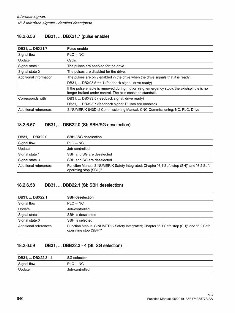
18.2.6.56 DB31, ... DBX21.7 (pulse enable)
DB31, ... DBX21.7 Pulse enableSignal flow PLC → NCUpdate CyclicSignal state 1 The pulses are enabled for the drive.Signal state 0 The pulses are disabled for the drive.Additional information The pulses are only enabled in the drive when the drive signals that it is ready:
DB31, ... DBX93.5 == 1 (feedback signal: drive ready)If the pulse enable is removed during motion (e.g. emergency stop), the axis/spindle is no longer braked under control. The axis coasts to standstill.
Corresponds with DB31, ... DBX93.5 (feedback signal: drive ready)DB31, ... DBX93.7 (feedback signal: Pulses are enabled)
Additional references SINUMERIK 840D sl Commissioning Manual, CNC Commissioning: NC, PLC, Drive
18.2.6.57 DB31, ... DBB22.0 (SI: SBH/SG deselection)
DB31, ... DBX22.0 SBH / SG deselection Signal flow PLC → NCUpdate Job-controlledSignal state 1 SBH and SG are deselectedSignal state 0 SBH and SG are deselectedAdditional references Function Manual SINUMERIK Safety Integrated; Chapter "6.1 Safe stop (SH)" and "6.2 Safe
operating stop (SBH)"
18.2.6.58 DB31, ... DBB22.1 (SI: SBH deselection)
DB31, ... DBX22.1 SBH deselection Signal flow PLC → NCUpdate Job-controlledSignal state 1 SBH is deselectedSignal state 0 SBH is selectedAdditional references Function Manual SINUMERIK Safety Integrated; Chapter "6.1 Safe stop (SH)" and "6.2 Safe
operating stop (SBH)"
18.2.6.59 DB31, ... DBB22.3 - 4 (SI: SG selection)
DB31, ... DBX22.3 - 4 SG selection Signal flow PLC → NCUpdate Job-controlled
Interface signals18.2 Interface signals - detailed description
PLC640 Function Manual, 06/2019, A5E47433877B AA

DB31, ... DBX22.3 - 4 SG selection Additional information When the SG function is active, the speed limit value is selected using the interface signals.
Bit 1 Bit 0 Meaning0 0 Speed limit value for SG1 is selected0 1 Speed limit value for SG2 is selected1 0 Speed limit value for SG3 is selected1 1 Speed limit value for SG4 is selected
Additional references Function Manual SINUMERIK Safety Integrated; Chapter "6.5 Safely reduced speed"
18.2.6.60 DB31, ... DBB23.0 - 2 (gear ratio selection)
DB31, ... DBX23.0 - 2 Gear ratio selection Signal flow PLC → NCUpdate Job-controlledAdditional information Bit 2 Bit 1 Bit 0 Meaning
0 0 0 Gearbox stage 1 is selected0 0 1 Gearbox stage 2 is selected0 1 0 Gearbox stage 3 is selected0 1 1 Gearbox stage 4 is selected1 0 0 Gearbox stage 5 is selected1 0 1 Gearbox stage 6 is selected1 1 0 Gearbox stage 7 is selected1 1 1 Gearbox stage 8 is selected
Additional references Function Manual, SINUMERIK Safety Integrated
18.2.6.61 DB31, ... DBB23.4 (SI: SE selection)
DB31, ... DBX23.4 SE selectionSignal flow PLC → NCUpdate Job-controlledAdditional information Selection of the safe software limit switch 1 or 2:
Bit 4 Meaning0 SE2 is selected1 SE1 is selected
Additional references Function Manual SINUMERIK Safety Integrated; Chapter "6.7 Safe software limit switch (SE)"
18.2.6.62 DB31, ... DBB24.1 (control axis)
DB31, ... DBX24.1 Control axis Signal flow PLC → NCUpdate Job-controlled
Interface signals18.2 Interface signals - detailed description
PLCFunction Manual, 06/2019, A5E47433877B AA 641

DB31, ... DBX24.1 Control axis Signal state 1 The axis-specific "Control axis" function is set using machine data MD30460_
$MA_BASE_FUNCTION_MASK.Bit 0 = 1: The axis traverses in speed mode
Signal state 0 Bit 0 = 0: Axis control is not allowedAdditional references SINUMERIK 840D sl List Manual, machine data
18.2.6.63 DB31, …DBX24.2 (MCS coupling: deactivate or do not permit)
DB31, …DBX24.2 MCS coupling: Deactivate or do not permitSignal flow PLC → NCUpdate Job-controlledSignal state 1 Deactivate MCS coupling - or do not permit is requestedSignal state 0 Deactivate MCS coupling - or do not permit is not requested.Additional information Notes
● The interface signal is only active if the axis is a slave axis of an MCS coupling● An active coupling is not deactivated until the relevant axes are stationary. ● If, with the interface signal set, CC_COPON (activate coupling) is programmed, then the
MCS coupling is not activated. No alarm is displayed.Corresponds with DB31, …DBX24.2 (MCS coupling: deactivate or do not permit)
DB31, ... DBX24.3 (MCS coupling: activate collision protection)DB31, ... DBX66.0 (MCS coupling: collision protection active)DB31, ... DBX97.0 (MCS coupling: slave axis)DB31, … DBX97.1 (MCS coupling: coupling active)DB31, ... DBX97.2 (MCS coupling: mirroring active)DB31, ... DBX97.3 (MCS coupling: offset change)
Additional references Function Manual, Special Functions; Chapter "TE6: MCS coupling"
18.2.6.64 DB31, ... DBX24.3 (MCS coupling: activate collision protection)
DB31, ... DBX24.3 MCS coupling: Activate collision protectionSignal flow PLC → NCUpdate CyclicSignal state 1 Activating the protection function for the axis pair is requested.Signal state 0 Activating the protection function for the axis pair is not requested.Additional information Activation
The protection function is activated if the interface signal for one of the two machine axes of the axis pair is set.Deactivation The protection function is deactivated if the interface signal for both machine axes of the axis pair is reset.
Interface signals18.2 Interface signals - detailed description
PLC642 Function Manual, 06/2019, A5E47433877B AA

DB31, ... DBX24.3 MCS coupling: Activate collision protectionCorresponds with DB31, …DBX24.2 (MCS coupling: deactivate or do not permit)
DB31, ... DBX24.3 (MCS coupling: activate collision protection)DB31, ... DBX66.0 (MCS coupling: collision protection active)DB31, ... DBX97.0 (MCS coupling: slave axis)DB31, … DBX97.1 (MCS coupling: coupling active)DB31, ... DBX97.2 (MCS coupling: mirroring active)DB31, ... DBX97.3 (MCS coupling: offset change)
Additional references Function Manual, Special Functions; Chapter "TE6: MCS coupling"
18.2.6.65 DB31, ... DBX24.4 (master-slave: activate torque compensatory controller)
DB31, ... DBX24.4 Master-slave: activate torque compensatory controllerSignal flow PLC → NCUpdate CyclicEdge change 0 → 1 Activation of the torque compensatory controller is requested.Edge change 1 → 0 Deactivation of the torque compensatory controller is requested.Additional information The torque compensatory controller can be activated for specific axes via the PLC interface
signal DB31, ... DBX24.4.Preconditions for activation:● Input of the supplementary speed setpoint is enabled:
MD37254 $MA_MS_TORQUE_CTRL_MODE[<slave axis>] = 1 ● The "fine" differential speed is reached:
DB31, ... DBX96.2 == 1Corresponds with DB31, ... DBX96.2 (master-slave: fine differential speed)
DB31, ... DBX96.4 (master-slave: compensatory controller active)MD37254 $MA_MS_TORQUE_CTRL_MODE (interconnection torque compensatory control‐ler)
Additional references Function Manual, Special Functions; Chapter "TE3: Speed/torque coupling, master-slave"
18.2.6.66 DB31, ... DBX24.5 (setpoint switchover: request drive control)
DB31, ... DBX24.5 Setpoint switchover: request drive controlSignal flow PLC → NCUpdate CyclicSignal state 1 Accepting the drive control is requested.Signal state 0 Accepting the drive control is not requested.
Interface signals18.2 Interface signals - detailed description
PLCFunction Manual, 06/2019, A5E47433877B AA 643

DB31, ... DBX24.5 Setpoint switchover: request drive controlAdditional information Notes
● If the request to accept the drive control is pending simultaneously in multiple axes, switchover does not occur. The drive control then remains with the axis in which it is currently active.
● If no transfer requests are pending when the control powers up, drive control is assigned by the control to the first of the axes found in the machine data (MD30110 $MA_CTRLOUT_MODULE_NR[<Achse>]) with the same logical drive number.
Corresponds with DB31, ... DBX96.5 (setpoint switchover: drive control active)Additional references Function Manual, Special Functions; Chapter "S9: setpoint switchover"
18.2.6.67 DB31, ... DBX24.7 (master-slave: activate coupling)
DB31, ... DBX24.7 Master-slave: activate couplingSignal flow PLC → NCUpdate CyclicEdge change 0 → 1 Activation of the master-slave coupling is requested.Edge change 1 → 0 Deactivation of the master-slave coupling is requested.Additional information A master-slave coupling can be activated/deactivated for specific axes via interface signal
DB31, ... DBX24.7.The following conditions must be satisfied for activating/deactivating a master-slave coupling:● MD37262 = 0: The master-slave coupling is not continuously active.● DB31, ... DBX61.5 == 1: Master and slave axis must be in position control.● DB31, ... DBX61.4 == 1 Master and slave axis must be stationary.● DB21, ... DBX35.7 == 1: the channels of the master and slave axes must be in the "Reset"
state.If a condition is not fulfilled, the coupling will not be activated or deactivated. An alarm is not output and the state of the coupling remains the same. If, at a later point, all conditions are fulfilled, the coupling will be activated or deactivated depending on the state of the signal.
Corresponds with DB31, ... DBX35.7 (reset channel status)DB31, ... DBX61.4 (axis/spindle stationary (n < nmin))DB31, ... DBX61.5 (position controller active)DB31, ... DBX96.7 (master-slave: coupling active)MD37262 $MA_MS_COUPLING_ALWAYS_ACTIVE (permanent master-slave coupling)
Additional references Function Manual, Special Functions; Chapter "TE3: Speed/torque coupling, master-slave"
18.2.6.68 DB31, ... DBX26.4 (enable following axis override)
DB31, ... DBX26.4 Enable following axis overrideSignal flow PLC → NCUpdate CyclicSignal state 1 Additional traversing motion can be overlaid on the following axis.Signal state 0 The following axis cannot be overlaid and traversed.
Interface signals18.2 Interface signals - detailed description
PLC644 Function Manual, 06/2019, A5E47433877B AA

DB31, ... DBX26.4 Enable following axis overrideAdditional information This signal is required for the flying synchronization of master and slave axes.
As long as the "Enable following axis overlay" signal stays set to "1", the following axis se‐lected with EGONSYN will traverse to synchronization in the EG coupling group. If the EG axis grouping includes modulo axes, their position values are reduced in the modulo, thereby ensuring that they approach the next possible synchronization.If, for the following axis "Enable following axis overlay" has notbeen set, then the axis it does not traverse to synchronization. Instead, the program is stopped at the EGONSYN block and the self-clearing alarm 16771 is issued.
Additional references Function Manual, Special Functions; Chapter "M3: axis couplings"
18.2.6.69 DB31, ... DBX28.0 (oscillation reversal from external)
DB31, ... DBX28.0 Oscillation reversal from externalSignal flow PLC → NCUpdate CyclicEdge change 0 → 1 Brake oscillation motion and move oscillation axis in the opposite direction with the oscillation
axis.Edge change 1 → 0 Continue oscillation without interruptionAdditional references Function Manual, Extended Functions; Chapter "P5: Oscillation"
18.2.6.70 DB31, ... DBX28.1 (PLC-controlled axis: Reset)
DB31, ... DBX28.1 PLC-controlled axis: ResetSignal flow PLC → NCUpdate CyclicEdge change 0 → 1 PLC-controlled axis: Reset is requestedEdge change 1 → 0 No effect.Additional information NC responses:
● The axis is transitioned into the "Single axis in Reset" status:$AA_SNGLAX_STAT == 1
● Stopped sequences are canceled. ● Internal axis states are reset.● Axis specific, machine data active at reset become active.● Execution is confirmed:
– DB31, ... DBX63.0 (reset executed) == 1– DB31, ... DBX63.2 (axis stop active) == 0
● Result: The axis is in the reset state.NoteIn conjunction with a channel reset, no axial machine data is active for axes controlled from the PLC.
Interface signals18.2 Interface signals - detailed description
PLCFunction Manual, 06/2019, A5E47433877B AA 645

DB31, ... DBX28.1 PLC-controlled axis: ResetCorresponds with DB31, ... DBX28.7 (PLC-controlled axis)
DB31, ... DBX63.1 (reset executed)DB31, ... DBX63.2 (axis stop active)System variable: $AA_SNGLAX_STAT (status of the single axis)OPI variable: aaSnglAxStat
Additional references Function Manual, Extended Functions; Chapter "P2: positioning axes"
18.2.6.71 DB31, ... DBX28.2 (PLC-controlled axis: Resume)
DB31, ... DBX28.2 PLC-controlled axis: ResumeSignal flow PLC → NCUpdate CyclicEdge change 0 → 1 PLC-controlled axis: Resume uninterrupted traversing motion is requestedEdge change 1 → 0 No effect.Additional information Using the signal, the traversing motion of an axis - controlled from the PLC - which is in the
"Single axis is interrupted" status ($AA_SNGLAX_STAT = 3), is resumed.NC responses:● Checks whether, for the axis, an axis-specific alarm with delete criterion
"CANCELCLEAR" or "NCSTARTCLEAR" is present? If yes, then this is deleted.● Checks whether axis motion can be resumed? If yes, then the axis makes the transition
into the "Single axis is active" state. $AA_SNGLAX_STAT == 4
● Execution is confirmed:– DB31,... DBX60.6 (position reached with exact stop coarse) == 0– DB31, ... DBX60.7 (position reached with exact stop fine) == 0– DB31, ... DBX63.2 (axis stop active) == 0– DB31, ... DBX64.6 / 7 (traversing command minus/plus) == 1
● Result: Traversing motion of the axis is resumed.NoteThe signal is ignored in the following cases:● The axis is not controlled by the PLC.● The axis is not in the "Single axis is interrupted" status.● It is not permissible that axis traversing motion resumes due to an active alarm.
Interface signals18.2 Interface signals - detailed description
PLC646 Function Manual, 06/2019, A5E47433877B AA

DB31, ... DBX28.2 PLC-controlled axis: ResumeCorresponds with DB31, ... DBX28.6 (PLC-controlled axis: Stop along braking ramp)
DB31, ... DBX28.7 (PLC-controlled axis)DB31, ... DBX60.6 (position reached with exact stop coarse)DB31, ... DBX60.7 (position reached with exact stop fine)DB31, ... DBX63.2 (axis stop active)DB31, ... DBX64.6 (traversing command "minus")DB31, ... DBX64.7 (traversing command "plus")System variable: $AA_SNGLAX_STAT (status of the single axis)OPI variable: aaSnglAxStat
Additional references Function Manual, Extended Functions; Chapter "P2: positioning axes"
18.2.6.72 DB31, ... DBX28.3 (set reversal point)
DB31, ... DBX28.3 Set reversal pointSignal flow PLC → NCUpdate CyclicSignal state 1 Reversal point 2Signal state 0 Reversal point 1Additional references Function Manual, Extended Functions; Chapter "P5: Oscillation"
18.2.6.73 DB31, ... DBX28.4 (change reversal point)
DB31, …DBX28.4 Change reversal pointSignal flow PLC → NCUpdate CyclicSignal state 1 The reversal point position can be changed by manually traversing the axis.
In conjunction with DB31, ...DBX28.0 (oscillation reversal from external):The position at which the axis is braked after "oscillation reversal from external", should be the new reversal point.
Signal state 0 The reversal point position cannot be changed by manually traversing the axis.In conjunction with DB31, ...DBX28.0 (oscillation reversal from external):No change of the reversal point position.
Additional information The braking position of the axis can be accepted as the new reversal position by means of the signal DB31, ... DBX28.4 (change reversal position). The signal DB31, ... DBX28.3 (set re‐versal point) is ignored, but rather the change affects the last initiated "Oscillation reversal from external" command.NoteFor the axis, it is not permissible that changing the reversal points via traversing keys or handwheel is active. In this case, display alarm 20081 "Braking position cannot be used as reversal point - handwheel active "is signaled.
Corresponds with DB31, ... DBX28.0 (oscillation reversal from external)DB31, ... DBX28.3 (set reversal point)
Additional references Function Manual, Extended Functions; Chapter "P5: Oscillation"
Interface signals18.2 Interface signals - detailed description
PLCFunction Manual, 06/2019, A5E47433877B AA 647

18.2.6.74 DB31, ... DBX28.5 (PLC-controlled axis: Stop at the next reversal point)
DB31, ... DBX28.5 PLC-controlled axis: Stop at the next reversal pointSignal flow PLC → NCUpdate CyclicSignal state 1 Interrupt oscillation motion of the PLC-controlled axis at the next reversal point.Signal state 0 There is no request to interrupt the oscillation motion of the PLC-controlled axis at the next
reversal point.Corresponds with DB31, ... DBX28.6 (PLC-controlled axis: Stop along braking ramp)
DB31, ... DBX28.7 (PLC-controlled axis)Additional references Function Manual, Extended Functions; Chapter "P5: Oscillation"
18.2.6.75 DB31, ... DBX28.6 (PLC-controlled axis: Stop along braking ramp)
DB31, ... DBX28.6 PLC-controlled axis: Stop along braking rampSignal flow PLC → NCUpdate CyclicSignal state 1 PLC-controlled axis: Braking the axis along a braking ramp is requested.Signal state 0 PLC-controlled axis: Braking the axis along a braking ramp is not requested.Additional information Using the signal, the traversing motion of an axis - controlled from the PLC - can be stopped.
NC responses:● The axis is braked down to standstill along its deceleration characteristic.● The axis is transitioned into the "Single axis is interrupted" status:
$AA_SNGLAX_STAT == 3● Execution is confirmed:
– DB31,... DBX60.6 (position reached with exact stop coarse) == 1– DB31, ... DBX60.7 (position reached with exact stop fine) == 1– DB31, ... DBX63.2 (axis stop active) == 0– DB31, ... DBX64.6 / 7 ("Plus" / "Minus" traversing command) == 0
● Result: Axis is stopped.NoteFollowing axis movements can only be suppressed when the leading axis stops.Retraction motion triggered by the "Extended stop and retract" function cannot be stopped.
Corresponds with DB31, ... DBX28.5 (PLC-controlled axis: Stop at the next reversal point)DB31, ... DBX28.7 (PLC-controlled axis)DB31, ... DBX60.6 (position reached with exact stop coarse)DB31, ... DBX60.7 (position reached with exact stop fine)DB31, ... DBX63.2 (axis stop active)DB31, ... DBX64.6 (traversing command "minus")DB31, ... DBX64.7 (traversing command "plus")System variable: $AA_SNGLAX_STAT (status of the single axis)OPI variable: aaSnglAxStat
Additional references Function Manual, Extended Functions; Chapter "P2: positioning axes"
Interface signals18.2 Interface signals - detailed description
PLC648 Function Manual, 06/2019, A5E47433877B AA

18.2.6.76 DB31, ... DBX28.7 (request, PLC-controlled axis)
DB31, ... DBX28.7 Request PLC-controlled axisSignal flow PLC → NCUpdate CyclicSignal state 1 Axis control should be relinquished to the PLC.Signal state 0 There is no request that axis control is transferred to the PLC.Additional information NC responses:
● Checks whether the axis is a main run axis or a neutral axis.● Checks whether an additional axis may be controlled from the PLC.● Transfer is confirmed:
– DB31, ... DBX63.1 (PLC controls axis) == 1– $AA_SNGLAX_STAT == 1
● Result: PLC controls axis.Corresponds with DB31, ... DBX63.1 (PLC-controlled axis)
System variable: $AA_SNGLAX_STAT (status of the single axis)OPI variable: aaSnglAxStat
Additional references Function Manual, Extended Functions; Chapter "P2: positioning axes"
18.2.6.77 DB31, ... DBX31.5 (disable synchronization)
DB31, ... DBX31.5 Disable synchronizationSignal flow PLC → NCUpdate CyclicSignal state 1 Synchronous spindle coupling: The PLC blocks synchronization motion for the following spin‐
dle specified by offset programming.Signal state 0 Synchronous spindle coupling: The PLC does not block synchronization motion for the fol‐
lowing spindle specified by offset programming.Additional information When the main run advances to a block with the part program
statement COUPON(<FS>,<LS>,<offset>), then interface signal DB31, ... DBX31.5 (block synchronization) is evaluated for the following spindle:● For DB31, ... DBX31.5 == 1, only continuous velocity synchronous operation is
established. The following spindle does not execute any additional movement. The coupling then responds analogously to a programmed COUPON(<FS>,<LS>).
● For DB31, ... DBX31.5 == 0, the axis only moves through the position offset.Corresponds with DB31, ... DBX84.4 (active spindle operating mode: Synchronous operation)
DB31, ... DBX98.1 (coarse synchronous operation)DB31, ... DBX98.0 (fine synchronous operation)
Additional references Function Manual, Extended Functions; Chapter "S3: Synchronous spindle"
Interface signals18.2 Interface signals - detailed description
PLCFunction Manual, 06/2019, A5E47433877B AA 649

18.2.6.78 DB31, ... DBX34.0 - 1 (setpoint limitation)
DB31, ... DBX34.0 - 1 Setpoint limitationSignal flow PLC → NCUpdate CyclicFurther information With the interface signals, one of the four setpoint speed limits parameterized in MD36933
$MA_SAFE_DES_VELO_LIMIT[0 ... 3] can be activated, irrespective of the active SG stage. Bit 1 Bit 0 Meaning: Activation of
0 0 MD36933 $MA_SAFE_DES_VELO_LIMIT[ 0 ]0 1 MD36933 $MA_SAFE_DES_VELO_LIMIT[ 1 ]1 0 MD36933 $MA_SAFE_DES_VELO_LIMIT[ 2 ]1 1 MD36933 $MA_SAFE_DES_VELO_LIMIT[ 3 ]
Corresponds with MD36933 $MA_SAFE_DES_VELO_LIMIT[0 ... 3]Additional references Function Manual, Safety Integrated
18.2.6.79 DB31, ... DBX60.0 (spindle / rotary axis)
DB31, ... DBX60.0 SpindleSignal flow NC → PLCUpdate CyclicSignal state 1 The machine axis is operated as a spindle in the following modes:
● Control mode● Oscillation mode● Positioning mode● Tapping with compensating chuck● Synchronous modeThe interface signals to the axis (DB31, ... DBB12 - DBB15) and from the axis (DB31, ... DBB74 - DBB81) are invalid.The interface signals to the spindle (DB31, ... DBB16 - DBB19) and from the spindle (DB31, ... DBB82 - DBB91) are valid.
Signal state 0 The machine axis is operated as rotary axis.The interface signals to the axis (DB31, ... DBB12 - DBB15) and from the axis (DB31, ... DBB74 - DBB81) are valid.The interface signals to the spindle (DB31, ... DBB16 - DBB19) and from the spindle (DB31, ... DBB82 - DBB91) are invalid.
Additional information If a machine axis is operated alternating as spindle or rotary axis, using the signal it is possible to identify which mode is currently active.● Turning machine: Spindle ↔ C axis● Milling machine: Spindle ↔ rotary axis for rigid tapping
Corresponds with DB31, ... DBB82 - DBB91Additional references Basic Functions Function Manual; Chapter "S1: spindles"
Interface signals18.2 Interface signals - detailed description
PLC650 Function Manual, 06/2019, A5E47433877B AA

18.2.6.80 DB31, ... DBX60.1 (NCU link axis active)
DB31, ... DBX60.1 NCU link: Axis activeSignal flow NC → PLCUpdate CyclicSignal state 1 The axis is active as NCU link axis.Signal state 0 The axis is not active as NCU link axis.Additional information The signal is irrelevant for a system with an NCU.Additional references ● Function Manual, Extended Functions; Chapter "B3: Distributed systems - 840D sl only"
● NCU Equipment Manual
18.2.6.81 DB31, ... DBX60.2 (encoder limit frequency exceeded 1)
DB31, ... DBX60.2 Encoder limit frequency exceeded, measuring system 1Signal flow NC → PLCUpdate CyclicSignal state 1 The encoder frequency limit of measuring system 2 has been exceeded ⇒
● DB31, ... .DBX60.4 = 0 (referenced/synchronized position measuring system 1)● DB31, ... .DBX61.5 = 0 (position controller active)● DB31, ... .DBX61.5 = 1 (speed controller active) only for a spindle● Axis is stopped (fast stop)
Signal state 0 The encoder frequency limit of measuring system 2 has not been exceeded, or after it was exceeded, the encoder frequency limit for encoder resynchronization was fallen below again:MD36302 $MA_ENC_FREQ_LIMIT_LOW
Additional information The encoder frequency limit to be monitored is set using the following machine data:MD36300 $MA_ENC_FREQ_LIMITThe monitoring of the encoder frequency limit always refers to the active measuring system selected in the NC/PLC interface: DB31, ... DBX1.5 / 6 (position measuring system 1 / 2)
Corresponds with DB31, ... DBX1.5 (position measuring system 1)DB31, ... DBX1.6 (position measuring system 2)MD36300 $MA_ENC_FREQ_LIMIT (encoder frequency limit)MD36302 $MA_ENC_FREQ_LIMIT_LOW (encoder frequency limit for encoder resynchroni‐zation)
Additional references Basic Functions Function Manual; Chapter "A3: Axis monitoring functions" > "Measuring system monitoring" > "Encoder frequency limit monitoring"
18.2.6.82 DB31, ... DBX60.3 (encoder frequency limit exceeded, measuring system 2)
DB31, ... DBX60.3 Encoder frequency limit exceeded, measuring system 2Signal flow NC → PLCUpdate Cyclic
Interface signals18.2 Interface signals - detailed description
PLCFunction Manual, 06/2019, A5E47433877B AA 651

DB31, ... DBX60.3 Encoder frequency limit exceeded, measuring system 2Signal state 1 The encoder frequency limit of measuring system 2 has been exceeded ⇒
● DB31, ... .DBX60.5 = 0 (referenced/synchronized position measuring system 2)● DB31, ... .DBX61.5 = 0 (position controller active)● DB31, ... .DBX61.5 = 1 (speed controller active) only for a spindle● Axis is stopped (fast stop)
Signal state 0 The encoder frequency limit of measuring system 2 has not been exceeded, or after it was exceeded, the encoder frequency limit for encoder resynchronization was fallen below again:MD36302 $MA_ENC_FREQ_LIMIT_LOW
Additional information The encoder frequency limit to be monitored is set using the following machine data:MD36300 $MA_ENC_FREQ_LIMITThe monitoring of the encoder frequency limit always refers to the active measuring system selected in the NC/PLC interface: DB31, ... DBX1.5 / 6 (position measuring system 1 / 2)
Corresponds with DB31, ... DBX1.5 (position measuring system 1)DB31, ... DBX1.6 (position measuring system 2)MD36300 $MA_ENC_FREQ_LIMIT (encoder frequency limit)MD36302 $MA_ENC_FREQ_LIMIT_LOW (encoder frequency limit for encoder resynchroni‐zation)
Additional references Basic Functions Function Manual; Chapter "A3: Axis monitoring functions" > "Measuring system monitoring" > "Encoder frequency limit monitoring"
18.2.6.83 DB31, ... DBX60.4 (referenced/synchronized 1)
DB31, ... DBX60.4 Referenced / synchronized 1Signal flow NC → PLCUpdate CyclicSignal state 1 Position measuring system 1 of the machine axis is referenced/synchronized.Signal state 0 Position measuring system 1 of the machine axis is not referenced/synchronized.Additional information Axis
After successful referencing or synchronizing, the interface signal is set SpindleThe interface signal is set at the latest after one spindle revolution (360 degrees), if the zero mark was passed or the contactless proximity switch has responded.
Corresponds with DB31, ... DBX1.6 (position measuring system 2)DB31, ... DBX2.4 - 7 (reference point value 1 to 4)DB31, ... DBX12.7 (reference point approach deceleration)DB31, ... DBX71.4 (position restored encoder 1)DB31, ... DBX71.5 (position restored encoder 2)MD34102 $MA_REFP_SYNC_ENCS (measuring system calibration)
Additional references Basic Functions Function Manual; Chapter "R1: referencing"
Interface signals18.2 Interface signals - detailed description
PLC652 Function Manual, 06/2019, A5E47433877B AA

18.2.6.84 DB31, ... DBX60.5 (referenced/synchronized 2)
DB31, ... DBX60.5 Referenced/synchronized 2Signal flow NC → PLCUpdate CyclicSignal state 1 Position measuring system 2 of the machine axis is referenced/synchronized.Signal state 0 Position measuring system 2 of the machine axis is not referenced/synchronized.Additional information Axis
After successful referencing or synchronizing, the interface signal is set SpindleThe interface signal is set at the latest after one spindle revolution (360 degrees), if the zero mark was passed or the contactless proximity switch has responded.
Corresponds with DB31, ... DBX1.6 (position measuring system 2)DB31, ... DBX2.4 - 7 (reference point value 1 to 4)DB31, ... DBX12.7 (reference point approach deceleration)DB31, ... DBX71.4 (position restored encoder 1)DB31, ... DBX71.5 (position restored encoder 2)MD34102 $MA_REFP_SYNC_ENCS (measuring system calibration)
Additional references Basic Functions Function Manual; Chapter "R1: referencing"
18.2.6.85 DB31,... DBX60.6 (position reached with exact stop coarse)
DB31, ... DBX60.6 Position reached with exact stop coarseSignal flow NC → PLCUpdate CyclicSignal state 1 At least one of the following states applies:
● The axis is not traversing, and the actual axis position is within the parameterized exact stop limit MD36000 $MA_STOP_LIMIT_COARSE
● The control system is in the "Reset" state● The axis was last programmed as positioning axis or positioning spindle.● Path motion was terminated with an NC stop.● The spindle is in closed-loop position control (SPCON/SPOS) and is stationary● The axis was switched over from closed-loop speed to closed-loop position control
Signal state 0 At least one of the following states applies:● The axis is traversing● Traversing motion is pending for the axis● The actual axis position lies outside the parameterized exact stop limit MD36000
$MA_STOP_LIMIT_COARSE● The spindle is in closed-loop speed control (SPCOF/SPOSA)● The axis is in the "Follow-up mode" state● The axis is in the "Park" state● The axis was switched over from closed-loop position to closed-loop speed control
Corresponds with MD36000 $MA_STOP_LIMIT_COARSE (exact stop coarse)
Interface signals18.2 Interface signals - detailed description
PLCFunction Manual, 06/2019, A5E47433877B AA 653
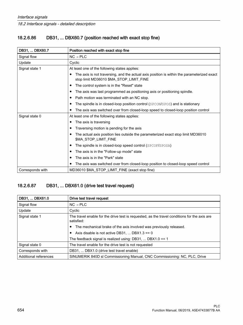
18.2.6.86 DB31, ... DBX60.7 (position reached with exact stop fine)
DB31, ... DBX60.7 Position reached with exact stop fineSignal flow NC → PLCUpdate CyclicSignal state 1 At least one of the following states applies:
● The axis is not traversing, and the actual axis position is within the parameterized exact stop limit MD36010 $MA_STOP_LIMIT_FINE
● The control system is in the "Reset" state● The axis was last programmed as positioning axis or positioning spindle.● Path motion was terminated with an NC stop.● The spindle is in closed-loop position control (SPCON/SPOS) and is stationary● The axis was switched over from closed-loop speed to closed-loop position control
Signal state 0 At least one of the following states applies:● The axis is traversing● Traversing motion is pending for the axis● The actual axis position lies outside the parameterized exact stop limit MD36010
$MA_STOP_LIMIT_FINE● The spindle is in closed-loop speed control (SPCOF/SPOSA)● The axis is in the "Follow-up mode" state● The axis is in the "Park" state● The axis was switched over from closed-loop position to closed-loop speed control
Corresponds with MD36010 $MA_STOP_LIMIT_FINE (exact stop fine)
18.2.6.87 DB31, ... DBX61.0 (drive test travel request)
DB31, ... DBX61.0 Drive test travel request Signal flow NC → PLCUpdate CyclicSignal state 1 The travel enable for the drive test is requested, as the travel conditions for the axis are
satisfied:● The mechanical brake of the axis involved was previously released.● Axis disable is not active DB31, ... DBX1.3 == 0The feedback signal is realized using: DB31, ... DBX1.0 == 1
Signal state 0 The travel enable for the drive test is not requestedCorresponds with DB31, ... DBX1.0 (drive test travel enable)Additional references SINUMERIK 840D sl Commissioning Manual, CNC Commissioning: NC, PLC, Drive
Interface signals18.2 Interface signals - detailed description
PLC654 Function Manual, 06/2019, A5E47433877B AA
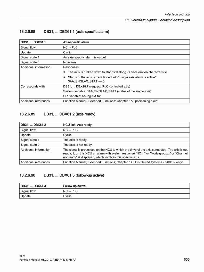
18.2.6.88 DB31, ... DBX61.1 (axis-specific alarm)
DB31, ... DBX61.1 Axis-specific alarmSignal flow NC → PLCUpdate CyclicSignal state 1 An axis-specific alarm is output.Signal state 0 No alarmAdditional information Responses:
● The axis is braked down to standstill along its deceleration characteristic.● Status of the axis is transitioned into "Single axis alarm is active":
$AA_SNGLAX_STAT == 5Corresponds with DB31, ... DBX28.7 (request, PLC-controlled axis)
System variable: $AA_SNGLAX_STAT (status of the single axis)OPI variable: aaSnglAxStat
Additional references Function Manual, Extended Functions; Chapter "P2: positioning axes"
18.2.6.89 DB31, ... DBX61.2 (axis ready)
DB31, ... DBX61.2 NCU link: Axis readySignal flow NC → PLCUpdate CyclicSignal state 1 The axis is ready.Signal state 0 The axis is not ready.Additional information The signal is processed on the NCU to which the drive of the axis connected. The axis is not
ready, if, on this NCU an alarm with system response "NC ..." or "Mode group..." or "Channel not ready" is displayed, which involves this specific axis.
Additional references Function Manual, Extended Functions; Chapter "B3: Distributed systems - 840D sl only"
18.2.6.90 DB31, ... DBX61.3 (follow-up active)
DB31, ... DBX61.3 Follow-up activeSignal flow NC → PLCUpdate Cyclic
Interface signals18.2 Interface signals - detailed description
PLCFunction Manual, 06/2019, A5E47433877B AA 655

DB31, ... DBX61.3 Follow-up activeSignal state 1 The follow-up mode for the axis/spindle is active.
Possible causes:● The controller enable for the drive has been withdrawn.
– DB31, ... .DBX2.1 == 0 (controller enable)– in the control for faults; see under "Additional reference"
● Follow-up mode was selected:– DB31, ... DBX1.4 == 1 (follow-up mode).– in the control, e.g. when withdrawing the controller enable for a traversing axis
During the follow-up mode: position setpoint = actual position valueNoteThe standstill and clamping monitoring are not active.
Signal state 0 The follow-up mode for the axis/spindle is not active.The standstill and clamping monitoring are active.
Additional information NoteIn the "Hold" state, the "Follow-up mode active" signal is not set.NoticeDelete distance-to-go is executed in the control for the following state transitions:● From the state "Follow-up" into the state "Hold" (DB31, ... DBX1.4 = 1 → 0 (follow-up
mode))● From the state "Follow-up" into the state "Position control" (DB31, ... .DBX2.1 = 1
(controller enable))Corresponds with DB31, ... DBX2.1 (controller enable)
DB31, ... DBX1.4 (follow-up mode)Additional references Diagnostics Manual
18.2.6.91 DB31, ... DBX61.4 (axis/spindle stationary (n < nmin))
DB31, ... DBX61.4 Axis/spindle stationary (n < nmin) (status)Signal flow NC → PLCUpdate CyclicSignal state 1 The axis/spindle is stationary This means that the actual velocity of the axis or the actual
speed of the spindle is less than or equal to the parameterized limit value:MD36060 $MA_STANDSTILL_VELO_TOL
Signal state 0 The axis/spindle is not stationary This means that the actual velocity of the axis or the actual speed of the spindle is greater than the parameterized limit value:MD36060 $MA_STANDSTILL_VELO_TOL If a travel command is present, e.g. for a spindle, then the signal is always = 0 - even if the actual speed lies below that specified in MD36060.If the interface signal:DB31, ... DBX61.4 (axis/spindle stationary)is signaled and there is no closed-loop position control active for the spindle, then at the user interface, an actual speed of zero is displayed and with the system variable $AA_S[n] zero is read.
Interface signals18.2 Interface signals - detailed description
PLC656 Function Manual, 06/2019, A5E47433877B AA
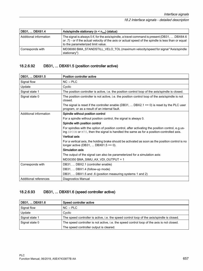
DB31, ... DBX61.4 Axis/spindle stationary (n < nmin) (status)Additional information The signal is always 0 if, for the axis/spindle, a travel command is present (DB31, ... .DBX64.6
or .7) - or if the actual velocity of the axis or actual speed of the spindle is less than or equal to the parameterized limit value.
Corresponds with MD36060 $MA_STANDSTILL_VELO_TOL (maximum velocity/speed for signal "Axis/spindle stationary")
18.2.6.92 DB31, ... DBX61.5 (position controller active)
DB31, ... DBX61.5 Position controller activeSignal flow NC → PLCUpdate CyclicSignal state 1 The position controller is active, i.e. the position control loop of the axis/spindle is closed.Signal state 0 The position controller is not active, i.e. the position control loop of the axis/spindle is not
closed.The signal is reset if the controller enable (DB31, ... DBX2.1 == 0) is reset by the PLC user program, or as a result of an internal fault.
Additional information Spindle without position controlFor a spindle without position control, the signal is always 0.Spindle with position controlFor spindles with the option of position control, after activating the position control, e.g.us‐ing SPCON or M70, then the signal is handled the same as for a position-controlled axis.Vertical axis For a vertical axis, the holding brake should be activated as soon as the position control is no longer active (DB31, ... DBX61.5 == 0).Simulation axisThe output of the signal can also be parameterized for a simulation axis:MD30350 $MA_SIMU_AX_VDI_OUTPUT = 1
Corresponds with DB31, ... DBX2.1 (controller enable)DB31, ... DBX1.4 (follow-up mode)DB31, ... DBX1.5 and .6 (position measuring systems 1 and 2)
Additional references Diagnostics Manual
18.2.6.93 DB31, ... DBX61.6 (speed controller active)
DB31, ... DBX61.6 Speed controller activeSignal flow NC → PLCUpdate CyclicSignal state 1 The speed controller is active, i.e. the speed control loop of the axis/spindle is closed.Signal state 0 The speed controller is not active, i.e. the speed control loop of the axis is not closed.
The speed controller output is cleared.
Interface signals18.2 Interface signals - detailed description
PLCFunction Manual, 06/2019, A5E47433877B AA 657

DB31, ... DBX61.6 Speed controller activeAdditional information Spindle without position control
If the spindle is not under position control, the signal can be used as a feedback signal for signal DB31, ... DBX2.1 (controller enable).Simulation axisThe output of the signal can also be parameterized for a simulation axis:MD30350 $MA_SIMU_AX_VDI_OUTPUT = 1
Corresponds with DB31, ... DBX61.5 (position controller active)
18.2.6.94 DB31, ... DBX61.7 (current controller active)
DB31, ... DBX61.7 Current controller activeSignal flow NC → PLCUpdate CyclicSignal state 1 The current controller is active, i.e. the current control loop of the axis/spindle is closed.Signal state 0 The current controller is not active, i.e. the current control loop of the axis is not closed.
The current controller output, including the injection variables on the control voltage, is cleared.
Corresponds with DB31, ... DBX61.5 (position controller active)DB31, ... DBX61.6 (speed controller active)
18.2.6.95 DB31, ... DBX62.0 (software cams active)
DB31, ... DBX62.0 Software cams activeSignal flow NC → PLCUpdate CyclicSignal state 1 The output of the minus and plus cam signals of an axis to the PLC interface is active.Signal state 0 The output of the minus and plus cam signals of an axis to the PLC interface is not active.Corresponds with DB10 DBX110.0 - 113.7 (software cams: minus cam signal 1 to 32)
DB10 DBX114.0 - 117.7 (software cams: plus cam signal 1 to 32)DB31, ... DBX2.0 (software cams: activation)
Additional references Function Manual, Extended Functions; Chapter "N3: software cams, position switching sig‐nals"
18.2.6.96 DB31, ... DBX62.1 (handwheel override active)
DB31, ... DBX62.1 Handwheel override activeSignal flow NC → PLCUpdate CyclicSignal state 1 The "Handwheel override in AUTOMATIC mode" function is active for the programmed po‐
sitioning axis (FDA[<axis>]).
Interface signals18.2 Interface signals - detailed description
PLC658 Function Manual, 06/2019, A5E47433877B AA
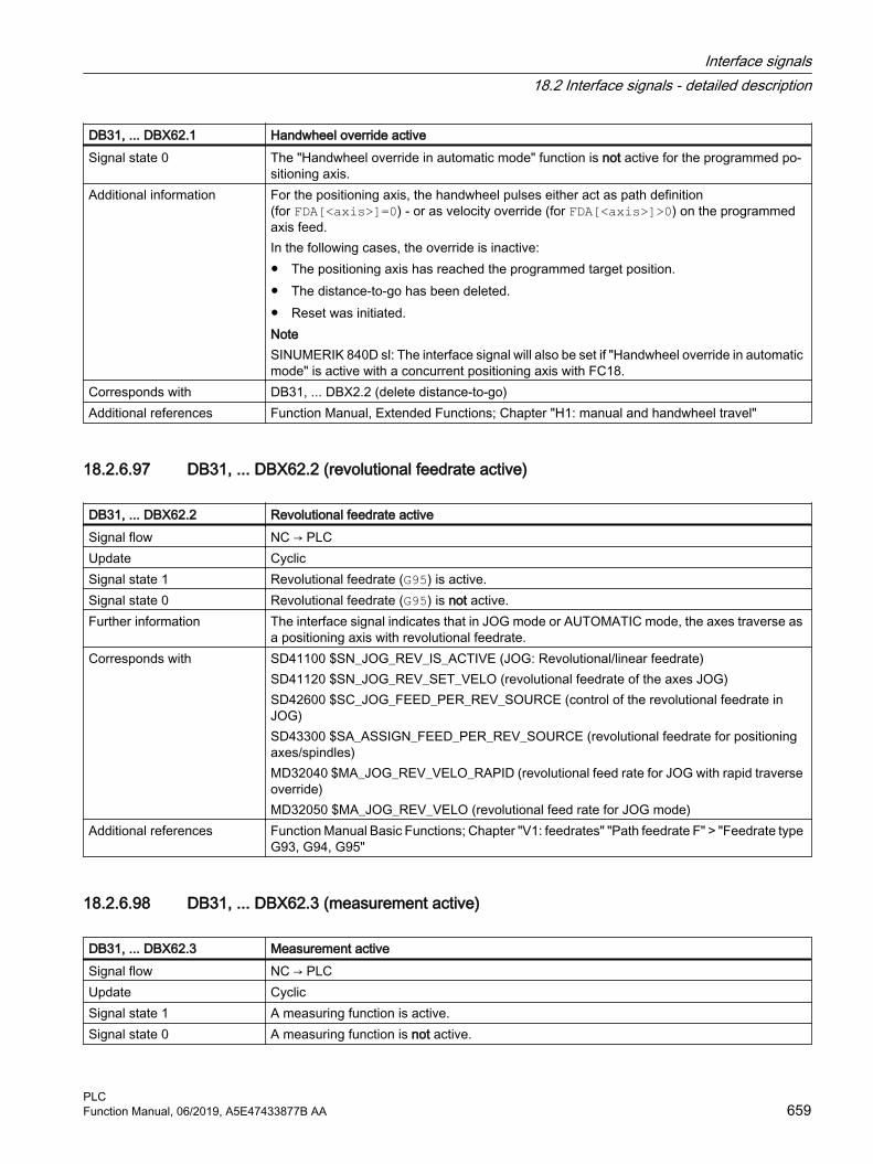
DB31, ... DBX62.1 Handwheel override activeSignal state 0 The "Handwheel override in automatic mode" function is not active for the programmed po‐
sitioning axis.Additional information For the positioning axis, the handwheel pulses either act as path definition
(for FDA[<axis>]=0) - or as velocity override (for FDA[<axis>]>0) on the programmed axis feed.In the following cases, the override is inactive:● The positioning axis has reached the programmed target position.● The distance-to-go has been deleted.● Reset was initiated.NoteSINUMERIK 840D sl: The interface signal will also be set if "Handwheel override in automatic mode" is active with a concurrent positioning axis with FC18.
Corresponds with DB31, ... DBX2.2 (delete distance-to-go)Additional references Function Manual, Extended Functions; Chapter "H1: manual and handwheel travel"
18.2.6.97 DB31, ... DBX62.2 (revolutional feedrate active)
DB31, ... DBX62.2 Revolutional feedrate activeSignal flow NC → PLCUpdate CyclicSignal state 1 Revolutional feedrate (G95) is active.Signal state 0 Revolutional feedrate (G95) is not active.Further information The interface signal indicates that in JOG mode or AUTOMATIC mode, the axes traverse as
a positioning axis with revolutional feedrate.Corresponds with SD41100 $SN_JOG_REV_IS_ACTIVE (JOG: Revolutional/linear feedrate)
SD41120 $SN_JOG_REV_SET_VELO (revolutional feedrate of the axes JOG)SD42600 $SC_JOG_FEED_PER_REV_SOURCE (control of the revolutional feedrate in JOG)SD43300 $SA_ASSIGN_FEED_PER_REV_SOURCE (revolutional feedrate for positioning axes/spindles)MD32040 $MA_JOG_REV_VELO_RAPID (revolutional feed rate for JOG with rapid traverse override)MD32050 $MA_JOG_REV_VELO (revolutional feed rate for JOG mode)
Additional references Function Manual Basic Functions; Chapter "V1: feedrates" "Path feedrate F" > "Feedrate type G93, G94, G95"
18.2.6.98 DB31, ... DBX62.3 (measurement active)
DB31, ... DBX62.3 Measurement activeSignal flow NC → PLCUpdate CyclicSignal state 1 A measuring function is active.Signal state 0 A measuring function is not active.
Interface signals18.2 Interface signals - detailed description
PLCFunction Manual, 06/2019, A5E47433877B AA 659

DB31, ... DBX62.3 Measurement activeAdditional information Interface signal DBX31, ... DBX62.3 shows the instantaneous measurement status of the
axis, and can be evaluated for all measuring functions.Additional references Function Manual, Extended Functions; Chapter "M5: Measuring"
18.2.6.99 DB31, ... DBX62.4 (activate travel to fixed stop)
DB31, ...DBX62.4 Activate travel to fixed stopSignal flow NC → PLCUpdate CyclicSignal state 1 Request to enable travel to fixed stop.Signal state 0 No requestAdditional information The feedback signal is realized via DB31, ... DBX3.1 (enable travel to fixed stop)Corresponds with DB31, ... DBX3.1 (enable travel to fixed stop)Additional references Function Manual, Basic Functions; Chapter "F1: Travel to fixed stop"
18.2.6.100 DB31, ... DBX62.5 (fixed stop reached)
DB31, ... DBX62.5 Fixed stop reachedSignal flow NC → PLCUpdate CyclicSignal state 1 Fixed stop has been reached.Signal state 0 Fixed stop has not been reached.Additional information Application example
In order that a programmable clamping torque can be specified, for analog drives, the signal is used to switch the actuator drive from closed-speed into closed-loop current or torque controlled operation.
Corresponds with DB31, ... DBX1.1 (acknowledge fixed stop reached).DB31, ... DBX1.2 (fixed stop sensor)DB31, ... DBX3.1 (enable travel to fixed stop)DB31, ... DBX62.4 (activate travel to fixed stop)DB31, ... DBX62.5 (fixed stop reached)
Additional references Function Manual, Basic Functions; Chapter "F1: Travel to fixed stop"
18.2.6.101 DB31, ... DBX62.7 (axis container rotation active)
DB31, ... DBX62.7 Axis container: Rotation activeSignal flow NC → PLCUpdate CyclicSignal state 1 An axis container rotation is active for the axis.Signal state 0 An axis container rotation is not active for the axis.Additional references Function Manual, Extended Functions; Chapter "B3: Distributed systems - 840D sl only"
Interface signals18.2 Interface signals - detailed description
PLC660 Function Manual, 06/2019, A5E47433877B AA
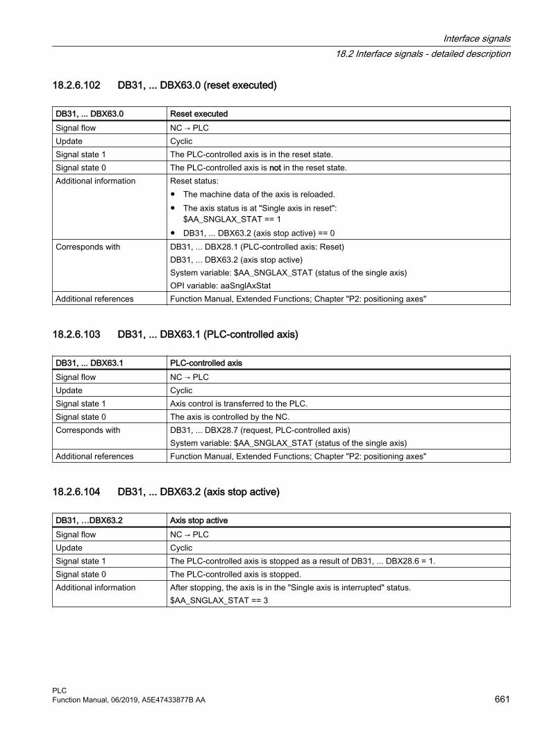
18.2.6.102 DB31, ... DBX63.0 (reset executed)
DB31, ... DBX63.0 Reset executedSignal flow NC → PLCUpdate CyclicSignal state 1 The PLC-controlled axis is in the reset state.Signal state 0 The PLC-controlled axis is not in the reset state.Additional information Reset status:
● The machine data of the axis is reloaded.● The axis status is at "Single axis in reset":
$AA_SNGLAX_STAT == 1● DB31, ... DBX63.2 (axis stop active) == 0
Corresponds with DB31, ... DBX28.1 (PLC-controlled axis: Reset)DB31, ... DBX63.2 (axis stop active)System variable: $AA_SNGLAX_STAT (status of the single axis)OPI variable: aaSnglAxStat
Additional references Function Manual, Extended Functions; Chapter "P2: positioning axes"
18.2.6.103 DB31, ... DBX63.1 (PLC-controlled axis)
DB31, ... DBX63.1 PLC-controlled axisSignal flow NC → PLCUpdate CyclicSignal state 1 Axis control is transferred to the PLC.Signal state 0 The axis is controlled by the NC.Corresponds with DB31, ... DBX28.7 (request, PLC-controlled axis)
System variable: $AA_SNGLAX_STAT (status of the single axis)Additional references Function Manual, Extended Functions; Chapter "P2: positioning axes"
18.2.6.104 DB31, ... DBX63.2 (axis stop active)
DB31, …DBX63.2 Axis stop activeSignal flow NC → PLCUpdate CyclicSignal state 1 The PLC-controlled axis is stopped as a result of DB31, ... DBX28.6 = 1.Signal state 0 The PLC-controlled axis is stopped.Additional information After stopping, the axis is in the "Single axis is interrupted" status.
$AA_SNGLAX_STAT == 3
Interface signals18.2 Interface signals - detailed description
PLCFunction Manual, 06/2019, A5E47433877B AA 661

DB31, …DBX63.2 Axis stop activeCorresponds with DB31, ... DBX28.6 (PLC-controlled axis: Stop along braking ramp)
DB31, ... DBX28.7 (PLC-controlled axis)DB31, ... DBX60.6 (position reached with exact stop coarse)DB31, ... DBX60.7 (position reached with exact stop fine)System variable: $AA_SNGLAX_STAT (status of the single axis)OPI variable: aaSnglAxStat
Additional references Function Manual, Extended Functions; Chapter "P2: positioning axes"
18.2.6.105 DB31, ... DBX63.3 (axis/spindle disable active)
DB31, ... DBX63.3 Axis/spindle disable activeSignal flow NC → PLCUpdate CyclicSignal state 1 Axis/spindle disable is active.Signal state 0 The axis/spindle disable is not active.Additional information An axis / spindle disable is requested via DB31, ... DBX1.3 = 1Corresponds with DB31, ... DBX1.3 (axis/spindle disable)
DB31, ... DBX14.1 (activate program test)DB21, ... DBX1.7 (activate program test)DB21, ... DBX33.7 (program test active)
Additional references Behavior in synchronous mode:Function Manual, Extended Functions; Synchronous Spindle (S3)
18.2.6.106 DB31, ... DBX64.0 - 2 (handwheel active)
DB31, ... DBX64.0 - 2 Handwheel activeSignal flow NC → PLCUpdate Cyclic
Interface signals18.2 Interface signals - detailed description
PLC662 Function Manual, 06/2019, A5E47433877B AA

DB31, ... DBX64.0 - 2 Handwheel activeAdditional information The interface can be interpreted either bit or binary-coded. The definition is realized using
machine data MD11324.Bit coded: maximum 3 handwheels Bit 2 Bit 1 Bit 0 Number of the assigned handwheel
0 0 0 No handwheel assignment0 0 1 10 1 0 21 0 0 3
Binary coded: maximum 6 handwheels Bit 2 Bit 1 Bit 0 Number of the assigned handwheel
0 0 0 No handwheel assignment0 0 1 10 1 0 20 1 1 31 0 0 41 0 1 51 1 0 6
If the assignment is active, the machine axis can be traversed with the handwheel in JOG mode or a DRF offset can be generated in AUTOMATIC or MDI mode.NoteAt any one time, the machine axis can only be assigned to one handwheel. If, for bit coding, several interface signals are set simultaneously, then the following priority applies: "Hand‐wheel 1" before "Handwheel 2" before "Handwheel 3".
Corresponds with DB31, ... DBX4.0 - 2 (activate handwheel)MD11324 $MN_HANDWH_VDI_REPRESENTATION (representation of the handwheel num‐ber at the VDI interface)
Additional references Function Manual, Extended Functions; Chapter "H1: manual and handwheel travel"
18.2.6.107 DB31, ... DBX64.4 - 5 ("Plus" / "Minus" traversing request)
DB31, ... DBX64.4 - 5 Traversing request "Plus" / "Minus"Signal flow NC → PLCUpdate CyclicSignal state 1 There is a traversing request for the machine axis.Signal state 0 There is no traversing request for the machine axis.
Interface signals18.2 Interface signals - detailed description
PLCFunction Manual, 06/2019, A5E47433877B AA 663

DB31, ... DBX64.4 - 5 Traversing request "Plus" / "Minus"Additional information Depending on the mode selected, the traversing request is initiated in different ways:
● JOG mode"Plus" or "Minus" traversing key
● REF modeTraversing key that initiates traversing motion in the direction of the reference point.
● AUTOMATIC or MDI modeA program block with a traversing operation is executed for a geometry axis.Bit 4 Traversing command "Minus", travel request in the negative axis directionBit 5 Traversing command "Plus" travel request in the positive axis direction
Corresponds with DB31, ... DBX4.6 - 7 (traversing keys "Plus" / "Minus")DB31, ... DBX64.6 - 7 ("Plus" / "Minus" traversing command)
Additional references Function Manual, Extended Functions; Chapter "H1: manual and handwheel travel"
18.2.6.108 DB31, ... DBX64.6 - 7 ("Plus" / "Minus" traversing command)
DB31, ... DBX64.6 - 7 Traversing command "Plus" / "Minus"Signal flow NC → PLCUpdate CyclicSignal state 1 A travel command is pending for the machine axisSignal state 0 No travel command is pending for the machine axisAdditional information The travel command is output depending on MD17900 $MN_VDI_FUNCTION_MASK, bit 0.
Bit 6 Travel command "Minus", for traversing in the negative axis directionBit 7 Travel command "Plus", for traversing in the positive axis direction
Application exampleReleasing the axis clamp when the traversing command is identified.NoteFor axes where clamping is not released until a drive command is detected, the continuous-path mode (G64) is not possible.
Corresponds with DB31, ... DBX4.6 - 7 (traversing keys "Plus" / "Minus")DB31, ... DBX64.4 - 5 (traversing request "Plus" / "Minus")MD17900 $MN_VDI_FUNCTION_MASK (setting for VDI signals)
Additional references Function Manual, Extended Functions; Chapter "H1: manual and handwheel travel"
18.2.6.109 DB31, ... DBX65.0 - 6 (active machine function)
DB31, ... DBX65.0 - 6 Active machine functionSignal flow NC → PLCUpdate CyclicSignal state 1 The machine function to manually traverse the machine axis is active.Signal state 0 The machine function to manually traverse the machine axis is not active .
Interface signals18.2 Interface signals - detailed description
PLC664 Function Manual, 06/2019, A5E47433877B AA

DB31, ... DBX65.0 - 6 Active machine functionAdditional information There is a signal for every machine function to manually traverse the machine axis in the JOG
mode.Bit 0 INC1Bit 1 INC10Bit 2 INC100Bit 3 INC1000Bit 4 INC10000Bit 5 INCvarBit 6 Continuous manual travel
NoteDepending on the machine function, the response when actuating the traversing key or the handwheel differs.
Corresponds with DB31, ... DBX5.0 - 6 (machine function request)Additional references Function Manual, Extended Functions; Chapter "H1: manual and handwheel travel"
18.2.6.110 DB31, ... DBX66.0 (MCS coupling: collision protection active)
DB31, …DBX66.0 MCS coupling: Collision protection activeSignal flow NC → PLCUpdate Job-controlledSignal state 1 Collision protection is active. Signal state 0 Collision protection is not active.Additional information Note:
The interface signal must be activated with: MD63543 $MD_CC_PROTECT_OPTIONS, bit 7 = 1
Corresponds with DB31, …DBX24.2 (MCS coupling: deactivate or do not permit)DB31, ... DBX24.3 (MCS coupling: activate collision protection)DB31, ... DBX66.0 (MCS coupling: collision protection active)DB31, ... DBX97.0 (MCS coupling: slave axis)DB31, … DBX97.1 (MCS coupling: coupling active)DB31, ... DBX97.2 (MCS coupling: mirroring active)DB31, ... DBX97.3 (MCS coupling: offset change)
Additional references Function Manual, Special Functions; Chapter "TE6: MCS coupling"
18.2.6.111 DB31, ... DBX67.0 (handwheel direction of rotation inversion active)
DB31, ...DBX67.0 Handwheel direction of rotation inversion activeSignal flow NC → PLCUpdate CyclicSignal state 1 The inversion of the direction of rotation of the handwheel assigned to the machine axis is
active.
Interface signals18.2 Interface signals - detailed description
PLCFunction Manual, 06/2019, A5E47433877B AA 665

DB31, ...DBX67.0 Handwheel direction of rotation inversion activeSignal state 0 The inversion of the direction of rotation of the handwheel assigned to the machine axis is not
active.Corresponds with DB31, ... DBX7.0 (invert handwheel direction of rotation)Additional references Function Manual, Extended Functions; Chapter "H1: manual and handwheel travel"
18.2.6.112 DB31, ... DBB68 (status axis/spindle replacement)
DB31, ... DBB68 Status axis/spindle replacementSignal flow PLC → NCUpdate CyclicAdditional information The current status of an axis with regard to axis/spindle replacement can be read by the PLC
user program via DBB68.Bit Meaning0 ... 3 Name of the channel to which the axis/spindle is assigned (binary code).
Example:The axis is assigned to channel 2:
Bit 3 Bit 2 Bit 1 Bit 0 Channel num‐ber
0 0 1 0 24 New axis type is requested from the PLC.5 Axis replacement is possible6 Axis is "neutral axis/spindle".7 Axis is "PLC axis/spindle".
Corresponds with DB31, ... DBB8 (request axis/spindle replacement)MD20070 $MC_AXCONF_MACHAX_USED (machine axis number valid in channel)MD30550 $MA_AXCONF_ASSIGN_MASTER_CHAN (initial setting of channel for axis re‐placement)
Additional references Function Manual, Extended Functions; Chapter "K10: Cross-channel axis interchange"
18.2.6.113 DB31, ... DBX69.0 - 2 (active position controller parameter set)
DB31, ... DBX69.0 - 2 Active position controller parameter setSignal flow NC → PLCUpdate Job-controlled
Interface signals18.2 Interface signals - detailed description
PLC666 Function Manual, 06/2019, A5E47433877B AA

DB31, ... DBX69.0 - 2 Active position controller parameter setAdditional information Bit 2 Bit 1 Bit 0 Parameter set
0 0 0 10 0 1 20 1 0 30 1 1 41 0 0 51 0 1 61 1 0 61 1 1 6
NoteThe interface is irrelevant when the switchover is deactivatedMD35590 $MA_PARAMSET_CHANGE_ENABLE == 0 In this case, the 1st parameter set is always active.
Corresponds with DB31, ...DBX9.0 - DBX9.2 (selection: position controller parameter set)
18.2.6.114 DB31, ... DBX70.0 (REPOS offset)
DB31, ... DBX70.0 REPOS offsetSignal flow NC → PLCUpdate CyclicSignal state 1 A REPOS offset must be applied for the axis.Signal state 0 No REPOS offset needs to be applied for the axis.Corresponds with DB21, ... DBX25.4 (REPOS mode activation)
DB21, ... DBX31.0 - 2 (REPOS mode)DB21, ... DBX31.4 (REPOS mode change)DB21, ... DBX319.0 (REPOS mode change acknowledgment)DB21, ... DBX319.1 - 3 (active REPOS mode)DB21, ... DBX319.5 (REPOS acknowledgment delay)DB31, ... DBX10.0 (REPOS delay)DB31, ... DBX70.1 (REPOS offset valid)DB31, ... DBX70.2 (REPOS delay acknowledgment)DB31, ... DBX72.0 (REPOS delay)DB31, ... DBX76.4 (path axis)MD11470 $MN_REPOS_MODE_MASK (repositioning properties)
Additional references Basic Functions Function Manual; Chapter "K1: Mode group, channel, program mode, reset response" > "Block search type 5 (SERUPRO)" > "Repositioning to the contour (REPOS)"
Interface signals18.2 Interface signals - detailed description
PLCFunction Manual, 06/2019, A5E47433877B AA 667

18.2.6.115 DB31, ... DBX70.1 (REPOS offset valid)
DB31, ... DBX70.1 REPOS offset validSignal flow NC → PLCUpdate CyclicSignal state 1 The REPOS offset has been calculated as validSignal state 0 The REPOS offset has been calculated as invalid.Corresponds with DB21, ... DBX25.4 (REPOS mode activation)
DB21, ... DBX31.0 - 2 (REPOS mode)DB21, ... DBX31.4 (REPOS mode change)DB21, ... DBX319.0 (REPOS mode change acknowledgment)DB21, ... DBX319.1 - 3 (active REPOS mode)DB21, ... DBX319.5 (REPOS acknowledgment delay)DB31, ... DBX10.0 (REPOS delay)DB31, ... DBX70.0 (REPOS offset)DB31, ... DBX70.2 (REPOS delay acknowledgment)DB31, ... DBX72.0 (REPOS delay)DB31, ... DBX76.4 (path axis)MD11470 $MN_REPOS_MODE_MASK (repositioning properties)
Additional references Basic Functions Function Manual; Chapter "K1: Mode group, channel, program mode, reset response" > "Block search type 5 (SERUPRO)" > "Repositioning to the contour (REPOS)"
18.2.6.116 DB31, ... DBX70.2 (REPOS delay acknowledgment)
DB31, ... DBX70.2 REPOS delay acknowledgmentSignal flow NC → PLCUpdate CyclicSignal state 1 The REPOS delay is acknowledged.
NoteA REPOS offset was pending for the axis and "REPOS delay" was active:DB31, ... DBX10.0 == 1 (REPOS delay)The axis was programmed within a traversing block, and the REPOS offset was applied.The interface signal behaves just like:DB21, ... DBX319.1 - 3 (REPOS approach mode acknowledgment)
Signal state 0 The REPOS delay is still not acknowledged - or there is no REPOS offset available.
Interface signals18.2 Interface signals - detailed description
PLC668 Function Manual, 06/2019, A5E47433877B AA

DB31, ... DBX70.2 REPOS delay acknowledgmentCorresponds with DB21, ... DBX25.4 (REPOS mode activation)
DB21, ... DBX31.0 - 2 (REPOS mode)DB21, ... DBX31.4 (REPOS mode change)DB21, ... DBX319.0 (REPOS mode change acknowledgment)DB21, ... DBX319.1 - 3 (active REPOS mode)DB21, ... DBX319.5 (REPOS acknowledgment delay)DB31, ... DBX10.0 (REPOS delay)DB31, ... DBX70.0 (REPOS offset)DB31, ... DBX70.1 (REPOS offset valid)DB31, ... DBX72.0 (REPOS delay)DB31, ... DBX76.4 (path axis)MD11470 $MN_REPOS_MODE_MASK (repositioning properties)
Additional references Basic Functions Function Manual; Chapter "K1: Mode group, channel, program mode, reset response" > "Block search type 5 (SERUPRO)" > "Repositioning to the contour (REPOS)"
18.2.6.117 DB31, ... DBX71.4 (position restored measuring system 1)
DB31, ... DBX71.4 Position restored, measuring system 1Signal flow NC → PLCUpdate CyclicSignal state 1 The position of measuring system 1 of the machine axis is restored.Signal state 0 The position of measuring system 1 of the machine axis is not restored.Additional information MD34210 $MA_ENC_REFP_STATE == 3
After the control system has powered up, for distance-coded, incremental measuring systems the last axis position buffered before switch off is restored. Referencing does not take place automatically. The position measuring system is in the "position restored" state.
Corresponds with DB31, ... DBX71.5 (position restored, measuring system 2)MD34102 $MA_REFP_SYNC_ENCS (measuring system calibration)MD34210 $MA_ENC_REFP_STATE (adjustment status absolute encoder)
Additional references Basic Functions Function Manual; Chapter "R1: referencing"
18.2.6.118 DB31, ... DBX71.5 (position restored, measuring system 2)
DB31, ... DBX71.5 Position restored, measuring system 2Signal flow NC → PLCUpdate CyclicSignal state 1 The position of measuring system 2 of the machine axis is restored.Signal state 0 The position of measuring system 2 of the machine axis is not restored.Additional information MD34210 $MA_ENC_REFP_STATE == 3
After the control system has powered up, for distance-coded, incremental measuring systems the last axis position buffered before switch off is restored. Referencing does not take place automatically. The position measuring system is in the "position restored" state.
Interface signals18.2 Interface signals - detailed description
PLCFunction Manual, 06/2019, A5E47433877B AA 669

DB31, ... DBX71.5 Position restored, measuring system 2Corresponds with DB31, ... DBX71.4 (position restored measuring system 1)
MD34102 $MA_REFP_SYNC_ENCS (measuring system calibration)MD34210 $MA_ENC_REFP_STATE (adjustment status absolute encoder)
Additional references Basic Functions Function Manual; Chapter "R1: referencing"
18.2.6.119 DB31, ... DBX72.0 (REPOS delay)
DB31, ... DBX72.0 REPOS delay activeSignal flow NC → PLCUpdate CyclicSignal state 1 The REPOS delay is active.
After a block search, a REPOS offset is applied for this axis. However it is not applied using the approach block, but rather using the next traversing block in which the axis is program‐med.
Signal state 0 A REPOS delay is not active.Additional information Note
If the machine axes are involved on a path (DB31, ... DBX76.4 == 1 (path axis)), then the interface signal is not active.
Corresponds with DB31, ... DBX72.0 (REPOS delay)Additional references Basic Functions Function Manual; Chapter "K1: Mode group, channel, program mode, reset
response" > "Block search type 5 (SERUPRO)" > "Repositioning to the contour (REPOS)"
18.2.6.120 DB31, ... DBX74.4 (modulo rotary axis: traversing range limits active)
DB31, ... DBX74.4 Modulo rotary axis: traversing range limits activeSignal flow NC → PLCUpdate CyclicSignal state 1 Traversing range limits (software limit switch, working area limits) active for modulo rotary
axes.Signal state 0 Traversing range limitation for modulo rotary axes not active.Additional information Note
The signal is irrelevant if linear axes/rotary axes do not have modulo functionality.Application exampleMounted rotary axis with monitoring
Corresponds with DB31, ... DBX12.4 (modulo rotary axis: activate traversing range limits)Additional references Function Manual, Extended Functions; Chapter "R2: rotary axes"
Interface signals18.2 Interface signals - detailed description
PLC670 Function Manual, 06/2019, A5E47433877B AA
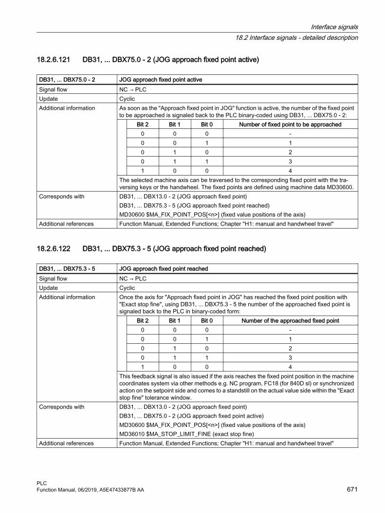
18.2.6.121 DB31, ... DBX75.0 - 2 (JOG approach fixed point active)
DB31, ... DBX75.0 - 2 JOG approach fixed point activeSignal flow NC → PLCUpdate CyclicAdditional information As soon as the "Approach fixed point in JOG" function is active, the number of the fixed point
to be approached is signaled back to the PLC binary-coded using DB31, ... DBX75.0 - 2: Bit 2 Bit 1 Bit 0 Number of fixed point to be approached
0 0 0 -0 0 1 10 1 0 20 1 1 31 0 0 4
The selected machine axis can be traversed to the corresponding fixed point with the tra‐versing keys or the handwheel. The fixed points are defined using machine data MD30600.
Corresponds with DB31, ... DBX13.0 - 2 (JOG approach fixed point)DB31, ... DBX75.3 - 5 (JOG approach fixed point reached)MD30600 $MA_FIX_POINT_POS[<n>] (fixed value positions of the axis)
Additional references Function Manual, Extended Functions; Chapter "H1: manual and handwheel travel"
18.2.6.122 DB31, ... DBX75.3 - 5 (JOG approach fixed point reached)
DB31, ... DBX75.3 - 5 JOG approach fixed point reachedSignal flow NC → PLCUpdate CyclicAdditional information Once the axis for "Approach fixed point in JOG" has reached the fixed point position with
"Exact stop fine", using DB31, ... DBX75.3 - 5 the number of the approached fixed point is signaled back to the PLC in binary-coded form: Bit 2 Bit 1 Bit 0 Number of the approached fixed point
0 0 0 -0 0 1 10 1 0 20 1 1 31 0 0 4
This feedback signal is also issued if the axis reaches the fixed point position in the machine coordinates system via other methods e.g. NC program, FC18 (for 840D sl) or synchronized action on the setpoint side and comes to a standstill on the actual value side within the "Exact stop fine" tolerance window.
Corresponds with DB31, ... DBX13.0 - 2 (JOG approach fixed point)DB31, ... DBX75.0 - 2 (JOG approach fixed point active)MD30600 $MA_FIX_POINT_POS[<n>] (fixed value positions of the axis)MD36010 $MA_STOP_LIMIT_FINE (exact stop fine)
Additional references Function Manual, Extended Functions; Chapter "H1: manual and handwheel travel"
Interface signals18.2 Interface signals - detailed description
PLCFunction Manual, 06/2019, A5E47433877B AA 671

18.2.6.123 DB31, ... DBX75.6 (JOG travel to position active)
DB31, ... DBX75.6 JOG travel to position activeSignal flow NC → PLCUpdate CyclicSignal state 1 The function "Position travel in JOG" is active.Signal state 0 The function "Position travel in JOG" is not activeAdditional information The selected machine axis can be traversed to the position specified with setting data
SD43320 using the traversing keys or the handwheel.Corresponds with DB31, ... DBX13.3 (JOG travel to position)
DB31, ... DBX75.7 (JOG position reached)SD43320 $SA_JOG_POSITION (JOG position)
Additional references Function Manual, Extended Functions; Chapter "H1: manual and handwheel travel"
18.2.6.124 DB31, ... DBX75.7 (JOG position reached)
DB31, ... DBX75.7 JOG position reachedSignal flow NC → PLCUpdate CyclicSignal state 1 For "Position travel in JOG", the axis has reached the position specified with SD43320 with
"Exact stop fine".Signal state 0 For "Position travel in JOG", the axis has still not reached the position specified with SD43320.Additional information Approaching the position is started with the traversing keys or the handwheel. The axis tra‐
verses until it comes to an automatic standstill at the position to be approached.Corresponds with DB31, ... DBX13.3 (JOG travel to position)
DB31, ... DBX75.6 (JOG travel to position active)SD43320 $SA_JOG_POSITION (JOG position)
Additional references Function Manual, Extended Functions; Chapter "H1: manual and handwheel travel"
18.2.6.125 DB31, ... DBX76.0 (lubrication pulse)
DB31, ... DBX76.0 Lubrication pulseSignal flow NC → PLCUpdate CyclicEdge change 0 → 1 The traversing path parameterized in machine data (MD33050 $MA_LUBRICATION_DIST)
was traversed.Edge change 1 → 0 The traversing path parameterized in machine data (MD33050 $MA_LUBRICATION_DIST)
was traversed.Additional information As soon as the axis/spindle has moved through the traversing distance set in machine data,
then the interface signal is inverted.The distance measurement is always restarted after the control powers up.
Corresponds with MD33050 $MA_LUBRICATION_DIST (lubrication pulse distance)
Interface signals18.2 Interface signals - detailed description
PLC672 Function Manual, 06/2019, A5E47433877B AA

18.2.6.126 DB31, ... DBX76.4 (path axis)
DB31, ... DBX76.4 Path axisSignal flow NC → PLCUpdate CyclicSignal state 1 The axis is not a path axis: This means that it is traversed with other axes along a path (path
axis).Signal state 0 The axis is not a path axis.Additional information Note
In conjunction with block search type 5 (SERUPRO) in the state: "Target block found" - the interface signal refers to the property of the axis in the target block.
Corresponds with DB31, ... DBX72.0 (REPOS delay)Additional references Basic Functions Function Manual; Chapter "K1: Mode group, channel, program mode, reset
response" > "Block search type 5 (SERUPRO)" > "Repositioning to the contour (REPOS)"
18.2.6.127 DB31, ... DBX76.5 (positioning axis)
DB31, ... DBX76.5 Positioning axisSignal flow NC → PLCUpdate CyclicSignal state 1 The axis is a positioning axis.Signal state 0 The axis is not a positioning axis.Corresponds with DB31, ... DBD78 (feedrate, positioning axis)Additional references Function Manual, Extended Functions; Chapter "P2: positioning axes"
18.2.6.128 DB31, ... DBX76.6 (indexing axis in position)
DB31, ... DBX76.6 Indexing axis in positionSignal flow NC → PLCUpdate CyclicSignal state 1 The signal is set to "1" in the following cases:
● The indexing axis has reached the indexing position with "Exact stop fine".● The indexing axis is located at the indexing position, which was approached in the
AUTOMATIC mode with CAC, CACP, CACN, CDC or CIC.Signal state 0 The signal is "0" in the following cases:
● The axis is not defined as an indexing axis.● A traversing command is active, and the indexing axis is traversed.● The indexing axis is located at a position which is not an indexing position.● In the AUTOMATIC mode, the indexing axis was not positioned using CAC, CACP, CACN,
CDC or CIC but instead is traversed to any position, for example with AC or DC.● The "Controller enable" of the indexing axis is withdrawn.
Interface signals18.2 Interface signals - detailed description
PLCFunction Manual, 06/2019, A5E47433877B AA 673

DB31, ... DBX76.6 Indexing axis in positionAdditional information Signal is irrelevant for axes that have not been defined as indexing axes.
Application exampleTool magazine: Activation of the gripper to remove the tool from the magazine is initiated as soon as the indexing axis is in position. The PLC user program must ensure this happens.Special cases or errorsThe axis positions entered in the indexing position table for the individual divisions can be changed using work offsets (including DRF).The interface signal "Indexing axis in position" is set if the actual position of the indexing axis assumes the position value entered into the indexing table plus the offset.If a DRF offset is applied to an indexing axis in AUTOMATIC mode, then the "Indexing axis in position" interface signal remains active even though the axis is no longer at an indexing position.
Corresponds with DB31, ... DBX64.6/64.7 (traversing command -/+)DB31, ... DBX2.1 (controller enable)MD30500 $MA_INDEX_AX_ASSIGN_POS_TAB (axis is an indexing axis)
Additional references Function Manual, Extended Functions; Chapter "T1: Indexing axes"
18.2.6.129 DB31, ... DBX77.0 (collision avoidance: Velocity reduction)
DB31, ... DBX77.0 Collision avoidance: Velocity reductionSignal flow NC → PLCUpdate CyclicSignal state 1 The traversing velocity of the axis is reduced by the collision avoidance.Signal state 0 The traversing velocity of the axis is not reduced by the collision avoidance.Additional references Function Manual, Special Functions; Chapter "K9: Collision avoidance"
18.2.6.130 DB31, ... DBD78 (feedrate, positioning axis)
DB31, ... DBD78 Feedrate, positioning axisSignal flow NC → PLCUpdate CyclicAdditional information The feedrate value of the axis can be read via the interface if this axis is traversed as posi‐
tioning axis.Type: REALThe output time is specified using machine data: MD22240 $MC_AUXFU_F_SYNC_TYPENotes● As default setting, the output is suppressed, because if the feedrate is output (auxiliary
function output) in the continuous-path mode, then the velocity can drop.● The last feedrate value is kept until it is overwritten by a new value.
Interface signals18.2 Interface signals - detailed description
PLC674 Function Manual, 06/2019, A5E47433877B AA

DB31, ... DBD78 Feedrate, positioning axisCorresponds with DB31, ... DBX76.5 (positioning axis)
MD22240 $MC_AUXFU_F_SYNC_TYPE (output time of F functions)MD32060 $MA_POS_AX_VELO (initial setting for positioning axis velocity)
Additional references Function Manual, Basic Functions; Chapter "V1: Feedrates" > "Feedrate for positioning axis (FA)"Function Manual, Extended Functions; Chapter "P2: positioning axes"
18.2.6.131 DB31, ... DBX82.0 - 2 (set gear stage)
DB31, ... DBX82.0 - 2 Set gear stageSignal flow NC → PLCUpdate CyclicAdditional information Gear stage requested from the NC, which must be selected at the machine.
Bit 2 Bit 1 Bit 0 Meaning:--- --- --- Axis mode0 0 0 Gear stage 10 0 1 Gear stage 10 1 0 Gear stage 20 1 1 Gear stage 31 0 0 Gear stage 41 0 1 Gear stage 51 1 0 Gear stage 51 1 1 Gear stage 5
Corresponds with DB31, ... DBX16.0 - 2 (actual gear stage)DB31, ... DBX16.3 (gear stage has been changed)DB31, ... DBX18.5 (oscillation speed)DB31, ... DBX82.3 (change over gear stage)
Additional references Basic Functions Function Manual; Chapter "S1: spindles"
18.2.6.132 DB31, ... DBX82.3 (change over gear stage)
DB31, ... DBX82.3 Change gear stage
Signal flow NC → PLCUpdate CyclicEdge change 0 → 1 There is an active requested to changeover the gear to the set gear stage.Edge change 1 → 0 No effect.Additional information Note
The gear is only changed over to the new set gear stage if the following applies: Set gear stage <> actual gear stage
Interface signals18.2 Interface signals - detailed description
PLCFunction Manual, 06/2019, A5E47433877B AA 675

DB31, ... DBX82.3 Change gear stage
Corresponds with DB31, ... DBX16.0 - 2 (actual gear stage)DB31, ... DBX82.0 - 2 (set gear stage)
Additional references Basic Functions Function Manual; Chapter "S1: spindles" > "Configurable gear adaptations" > "Gear stages for spindles and gear stage change"
18.2.6.133 DB31, ... DBX83.0 (speed limit exceeded)
DB31, ... DBX83.0 Speed limit exceededSignal flow NC → PLCUpdate CyclicSignal state 1 The speed limit is exceeded.Signal state 0 The speed limit is not exceeded.Additional information The speed limit is exceeded if the following applies.
Actual speed > (MD35100 $MA_SPIND_VELO_ LIMIT + MD35150 $MA_SPIND_DES_VE‐LO_TOL)
Corresponds with MD35150 $MA_SPIND_DES_VELO_TOL (spindle speed tolerance)MD35100 $MA_SPIND_VELO_LIMIT (maximum spindle speed)
Additional references Basic Functions Function Manual; Chapter "S1: spindles"
18.2.6.134 DB31, ... DBX83.1 (speed setpoint limited)
DB31, ... DBX83.1 Setpoint speed limitedSignal flow NC → PLCUpdate CyclicSignal state 1 The setpoint speed is limited.Signal state 0 The setpoint speed is not limited.
Interface signals18.2 Interface signals - detailed description
PLC676 Function Manual, 06/2019, A5E47433877B AA
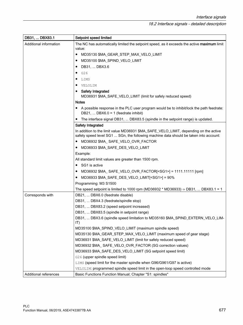
DB31, ... DBX83.1 Setpoint speed limitedAdditional information The NC has automatically limited the setpoint speed, as it exceeds the active maximum limit
value:● MD35130 $MA_GEAR_STEP_MAX_VELO_LIMIT● MD35100 $MA_SPIND_VELO_LIMIT● DB31, ... DBX3.6● G26● LIMS● VELOLIM● Safety Integrated
MD36931 $MA_SAFE_VELO_LIMIT (limit for safely reduced speed)Notes● A possible response in the PLC user program would be to inhibit/lock the path feedrate:
DB21, ... DBX6.0 = 1 (feedrate inhibit)● The interface signal DB31, ... DBX83.5 (spindle in the setpoint range) is updated.Safety IntegratedIn addition to the limit value MD36931 $MA_SAFE_VELO_LIMIT, depending on the active safety speed level SG1 ... SGn, the following machine data should be taken into account:● MD36932 $MA_ SAFE_VELO_OVR_FACTOR● MD36933 $MA_SAFE_DES_VELO_LIMITExample:All standard limit values are greater than 1500 rpm. ● SG1 is active● MD36932 $MA_ SAFE_VELO_OVR_FACTOR[<SG1>] = 1111.11111 [rpm]● MD36933 $MA_SAFE_DES_VELO_LIMIT[<SG1>] = 90%Programming: M3 S1500The speed setpoint is limited to 1000 rpm (MD36932 * MD36933) ⇒ DB31, ... DBX83.1 = 1
Corresponds with DB21, ... DBX6.0 (feedrate disable)DB31, ... DBX4.3 (feedrate/spindle stop)DB31, ... DBX83.2 (speed setpoint increased)DB31, ... DBX83.5 (spindle in setpoint range) DB31, ... DBX3.6 (spindle speed limitation to MD35160 $MA_SPIND_EXTERN_VELO_LIM‐IT)MD35100 $MA_SPIND_VELO_LIMIT (maximum spindle speed)MD35130 $MA_GEAR_STEP_MAX_VELO_LIMIT (maximum speed of gear stage)MD36931 $MA_SAFE_VELO_LIMIT (limit for safely reduced speed)MD36932 $MA_ SAFE_VELO_OVR_FACTOR (SG correction values)MD36933 $MA_SAFE_DES_VELO_LIMIT (SG setpoint speed limit)G26 (upper spindle speed limit)LIMS (speed limit for the master spindle when G96/G961/G97 is active)VELOLIM: programmed spindle speed limit in the open-loop speed controlled mode
Additional references Basic Functions Function Manual; Chapter "S1: spindles"
Interface signals18.2 Interface signals - detailed description
PLCFunction Manual, 06/2019, A5E47433877B AA 677

18.2.6.135 DB31, ... DBX83.2 (speed setpoint increased)
DB31, ... DBX83.2 Setpoint speed increasedSignal flow NC → PLCUpdate CyclicSignal state 1 The setpoint speed was increased.Signal state 0 The setpoint speed was not increased.Additional information The NC has automatically increased the setpoint speed, as it had fallen below the
active minimum limit value:● MD35120 $MA_GEAR_STEP_MIN_VELO● MD35140 $MA_GEAR_STEP_MIN_VELO_LIMIT● G25Notes● A possible response in the PLC user program would be to inhibit/lock the path feedrate:
DB21, ... DBX6.0 = 1 (feedrate inhibit)● The interface signal DB31, ... DBX83.5 (spindle in the setpoint range) is updated.
Corresponds with DB21, ... DBX6.0 (feedrate disable)DB31, ... DBX4.3 (feedrate/spindle stop)DB31, ... DBX83.1 (speed setpoint limited)DB31, ... DBX83.5 (spindle in setpoint range) MD35120 $MA_GEAR_STEP_MIN_VELO (minimum speed for automatic gear stage selec‐tion M40)MD35140 $MA_GEAR_STEP_MIN_VELO_LIMIT (minimum speed of the gear stage)G25 (lower spindle speed limitation)
Additional references Basic Functions Function Manual; Chapter "S1: spindles"
18.2.6.136 DB31, ... DBX83.3 (geometry monitoring)
DB31, ... DBX83.3 Geometry monitoringSignal flow NC → PLCSignal state 1 Error in the grinding wheel geometry
The actual wheel radius falls below the value specified in parameter $TC_TPG3 or the actual wheel width ($TC_TPG5) falls below the value defined in parameter $TC_TPG4.NoteThere is no controller-internal error response. Required responses must be programmed by the PLC user.
Signal state 0 No error in the grinding wheel geometryAdditional information The geometry monitoring is a subfunction of the grinding-specific tool monitoring. The actual
wheel radius and the actual wheel width are monitored.Additional references Function Manual, Extended Functions; Chapter "W4: Grinding-specific tool offset and tool
monitoring"
Interface signals18.2 Interface signals - detailed description
PLC678 Function Manual, 06/2019, A5E47433877B AA

18.2.6.137 DB31, ... DBX83.5 (spindle in setpoint range)
DB31, ... DBX83.5 Spindle in setpoint rangeSignal flow NC → PLCUpdate CyclicSignal state 1 The spindle speed is in the setpoint range.Signal state 0 The spindle speed is not in the setpoint range.Additional information The spindle speed is in the setpoint range if the following applies.
| Actual speed - setpoint speed | < MD35150 $MA_SPIND_DES_VELO_TOLNoteIt is normal if the spindle speed is not in the setpoint range while accelerating or braking.
Corresponds with DB21, ... DBX6.0 (feedrate disable)DB31, ... DBX4.3 (feedrate/spindle stop)DB31, ... DBX83.1 (speed setpoint limited)DB31, ... DBX83.2 (speed setpoint increased)
Additional references
18.2.6.138 DB31, ... DBX83.6 (speed monitoring)
DB31, ... DBX83.6 Speed monitoringSignal flow NC → PLCSignal state 1 Error in grinding wheel speed
The speed limit value is reached, the speed is limited to the limit value.NoteThere is no controller-internal error response. Required responses must be programmed by the PLC user.
Signal state 0 No error in grinding wheel speedAdditional information The speed monitoring is a subfunction of the grinding-specific tool monitoring. The speed
monitor checks the grinding wheel peripheral speed in m/s (parameter $TC_TPG7) as well as the maximum spindle speed in rpm (parameter $TC_TPG6). The speed setpoint is monitored against the speed limitation cyclically with allowance for the spindle override.
Additional references Function Manual, Extended Functions; Chapter "W4: Grinding-specific tool offset and tool monitoring"
18.2.6.139 DB31, ... DBX83.7 (clockwise actual direction of rotation)
DB31, ... DBX83.7 Actual direction of rotation clockwiseSignal flow NC → PLCUpdate CyclicSignal state 1 Actual direction of rotation: ClockwiseSignal state 0 Actual direction of rotation: Counterclockwise
Interface signals18.2 Interface signals - detailed description
PLCFunction Manual, 06/2019, A5E47433877B AA 679

DB31, ... DBX83.7 Actual direction of rotation clockwiseAdditional information The actual direction of rotation is derived from the spindle position measuring encoder.
NoteThe interface signal is irrelevant for:● DB31, ... DBX61.4 == 1 (axis/spindle stationary)● Spindles without position encoder
Corresponds with DB31, ... DBX61.4 (axis/spindle stationary)Additional references Basic Functions Function Manual; Chapter "S1: spindles"
18.2.6.140 DB31, ... DBX84.1 (grinding wheel peripheral speed active)
DB31, ... DBX84.1 Grinding wheel peripheral speed activeSignal flow NC → PLCSignal state 1 The function "constant grinding wheel peripheral speed (GWPS)" is active.Signal state 0 The function "Constant grinding wheel peripheral speed (GWPS)" is not active.Additional information If the function is active, then all S value inputs from the PLC are interpreted as the grinding
wheel peripheral speed.Additional references Function Manual, Extended Functions; Chapter "W4: Grinding-specific tool offset and tool
monitoring"
18.2.6.141 DB31, ... DBX84.3 (tapping without compensating check active)
DB31, ... DBX84.3 Tapping without compensating chuck activeSignal flow NC → PLCUpdate CyclicSignal state 1 Rigid tapping (without compensating chuck) active Signal state 0 Rigid tapping (without compensating chuck) not active Additional information If "Rigid tapping without compensating chuck" (G331/G332) is active, then internally the spin‐
dle is switched over into closed-loop position controlled axis mode. NoticeSetting the following interface signals while tapping without compensating chuck (rigid tap‐ping) will destroy the thread:● DB11, … DBX0.7 (mode group reset) = 1● DB21, ... DBX7.7 (channel reset) = 1● DB31, ... DBX2.1 (controller enable) = 0● DB31, ... DBX4.3 (feedrate stop) = 1
Corresponds with DB11, … DBX0.7 (mode group reset)DB21, ... DBX7.7 (channel reset)DB31, ... DBX2.1 (controller enable)DB31, ... DBX4.3 (feedrate stop)
Additional references Basic Functions Function Manual; Chapter "S1: spindles"
Interface signals18.2 Interface signals - detailed description
PLC680 Function Manual, 06/2019, A5E47433877B AA

18.2.6.142 DB31, ... DBX84.4 (active spindle operating mode: Synchronous operation)
DB31, ... DBX84.4 Active spindle mode: Synchronous modeSignal flow NC → PLCUpdate CyclicSignal state 1 The spindle is in the "synchronous mode".
NoteThe signal is only set for the machine axis which is active as following spindle:DB31, ... DBX99.1 (following spindle active) == 1
Signal state 0 The spindle is not operated as a following spindle in the "synchronous mode".Additional information In the synchronous mode, the following spindle tracks the motion of the leading spindle cor‐
responding to the ratio and the monitoring functions are active for coarse and fine synchron‐ism.When deactivating the coupling (deselection of synchronous mode), the following spindle is switched to the "control mode".
Corresponds with DB31, ... DBX98.0 (fine synchronous operation)DB31, ... DBX98.1 (coarse synchronous operation)DB31, ... DBX99.1 (following spindle active)
Additional references Function Manual, Extended Functions; Chapter "S3: Synchronous spindle"
18.2.6.143 DB31, ... DBX84.5 (active spindle mode: positioning mode)
DB31, ... DBX84.5 Active spindle mode: Positioning modeSignal flow NC → PLCUpdate CyclicSignal state 1 Positioning mode (SPOS or SPOSA) is active.Signal state 0 Positioning mode (SPOS or SPOSA) is not active.Corresponds with DB31, ... DBX84.6 (spindle mode, oscillation mode)
DB31, ... DBX84.7 (spindle mode, control mode)Additional references Basic Functions Function Manual; Chapter "S1: spindles" > "Configurable gear adaptations"
> "Gear stage change to fixed position"
18.2.6.144 DB31, ... DBX84.6 (active spindle mode: oscillating mode)
DB31, ... DBX84.6 Active spindle mode: Oscillation modeSignal flow NC → PLCUpdate CyclicSignal state 1 Oscillation mode is active.Signal state 0 Oscillation mode is not active.Additional information Note
When the gear stage is changed over, the spindle automatically goes into the oscillation mode.
Interface signals18.2 Interface signals - detailed description
PLCFunction Manual, 06/2019, A5E47433877B AA 681

DB31, ... DBX84.6 Active spindle mode: Oscillation modeCorresponds with DB31, ... DBX82.3 (change over gear stage)
DB31, ... DBX84.5 (spindle mode, positioning mode)DB31, ... DBX84.7 (spindle mode, control mode)
Additional references Basic Functions Function Manual; Chapter "S1: spindles"
18.2.6.145 DB31, ... DBX84.7 (active spindle mode: control mode)
DB31, ... DBX84.7 Active spindle mode: Control modeSignal flow NC → PLCUpdate CyclicSignal state 1 Control mode is activeSignal state 0 Control mode is notactive.Additional information The spindle is in control mode for the following functions:
● Spindle direction of rotation specified by M3/M4 or spindle stop M5● M41...M45, or automatic gear stage change M40
Corresponds with DB31, ... DBX84.5 (spindle mode, positioning mode)DB31, ... DBX84.6 (spindle mode, oscillation mode)
Additional references Basic Functions Function Manual; Chapter "S1: spindles"
18.2.6.146 DB31, ... DBX85.0 (tool with dynamic response limitation)
DB31, ... DBX85.0 Tool with dynamic response limitationSignal flow NC → PLCUpdate CyclicSignal state 1 After a tool change on the spindle, it is shown that a tool with dynamic response limitation is
in the spindle. To do this, the PLC acknowledgments are evaluated.The assignment state of the spindles is checked, especially if all tools have a maximum tool speed, which may be very high so that there is no effective limiting.
Signal state 0 The tool does not contain a parameterized dynamic response limitation.Corresponds with Option "Tool monitoring for maximum speed"
Tool data TC_TP_MAX_VELO >0 or TC_TP_MAX_ACC >0 Additional references Function Manual, Tool Management
18.2.6.147 DB31, ... DBX85.5 (spindle in position)
DB31, ... DBX85.5 Spindle in position Signal flow NC → PLCUpdate CyclicSignal state 1 The spindle is in position.Signal state 0 The spindle is not in position.
Interface signals18.2 Interface signals - detailed description
PLC682 Function Manual, 06/2019, A5E47433877B AA

DB31, ... DBX85.5 Spindle in position Additional information Precondition for the output of the interface signal:
● DB31, ... DBX60.7 == 1 (exact stop fine) AND● Programmed setpoint position is reachedNote● The interface signal is only processed in the positioning mode (DB31, ... DBX84.5 == 1),
e.g.:– NC program: SPOS, SPOSA and M19:– Synchronized action: SPOS and M19– PLC user program: Positioning with FC18 or DB31, ... DBX30.4
● The interface signal remains set if the spindle is already at the programmed setpoint position.
Corresponds with DB31, … DBX30.4 (spindle positioning start)DB31, ... DBX60.7 (exact stop fine)DB31, ... DBX84.5 (spindle mode, positioning mode)SPOSSPOSAM19
Additional references Basic Functions Function Manual; Chapter "S1: spindles" > ● "Modes" > "Positioning mode" > "Signal "Spindle in position" for tool change"● "Programming" > "Special spindle motion via PLC interface"
18.2.6.148 DB31, ... DBW86 (M function for spindle)
DB31, ... DBW86 M function for spindleSignal flow NC → PLCUpdate Job-controlledAdditional information The M function programmed for the spindle in the NC program is output.
Value M function3 M3 (clockwise spindle rotation)4 M4 (counterclockwise spindle rotation)5 M5 (spindle stop)19 M19 (spindle positioning to the position entered in SD43240)70 M70 (switchover in axis operation)
Corresponds with DB21, ... DBX58.0 - 4 (M function: change)DB21, ... DBX59.0 - 4 (M function: not decoded)DB21, ... DBB68 - 97 (M functions for spindles)
Interface signals18.2 Interface signals - detailed description
PLCFunction Manual, 06/2019, A5E47433877B AA 683

18.2.6.149 DB31, ... DBD88 (S function for spindle)
DB31, ... DBD88 S function for spindleSignal flow NC → PLCUpdate Job-controlledAdditional information The spindle-specific S function programmed in the NC program is output.
The following S functions are checked:● S.... as spindle speed in rpm (programmed value)● S .... as constant cutting rate in m/min or ft/minThe following S functions are not output:● S.... as the programmed spindle speed limiting G25● S.... as the programmed spindle speed limiting G26● S .... as spindle speed in rpm if a spindle was not defined in the control system● S.... as the dwell time in spindle revolutions
Corresponds with DB21, ... DBX60.0 - 2 (S function: change)DB21, ... DBX60.4 - 6 (S function: Quick)DB21, ... DBB98 - 115 (S functions for spindles), channel-specific
18.2.6.150 DB31, ... DBX92.1 (ramp-function generator disable active)
DB31, ... DBX92.1 Ramp-function generator disableSignal flow NC → PLCUpdate CyclicSignal state 1 Ramp function generator fast stop is active for the axis drive.Signal state 0 Ramp function generator fast stop is not active for the axis drive.Corresponds with DB31, ... DBX20.1 (ramp-function generator fast stop)Additional references SINUMERIK 840D sl Commissioning Manual, CNC Commissioning: NC, PLC, Drive
18.2.6.151 DB31, ... DBX92.4 (drive-autonomous motion active)
DB31, ... DBX92.4 Drive-autonomous motion activeSignal flow NC → PLCUpdate CyclicSignal state 1 Drive-autonomous motion is active.
The axis traverses due to setpoints generated by drive-internal functions. The drive still re‐sponds to control signals of the NC, e.g. controller enable. Setpoints from the NC are ignored.
Signal state 0 Drive-autonomous motion is not active.
Interface signals18.2 Interface signals - detailed description
PLC684 Function Manual, 06/2019, A5E47433877B AA
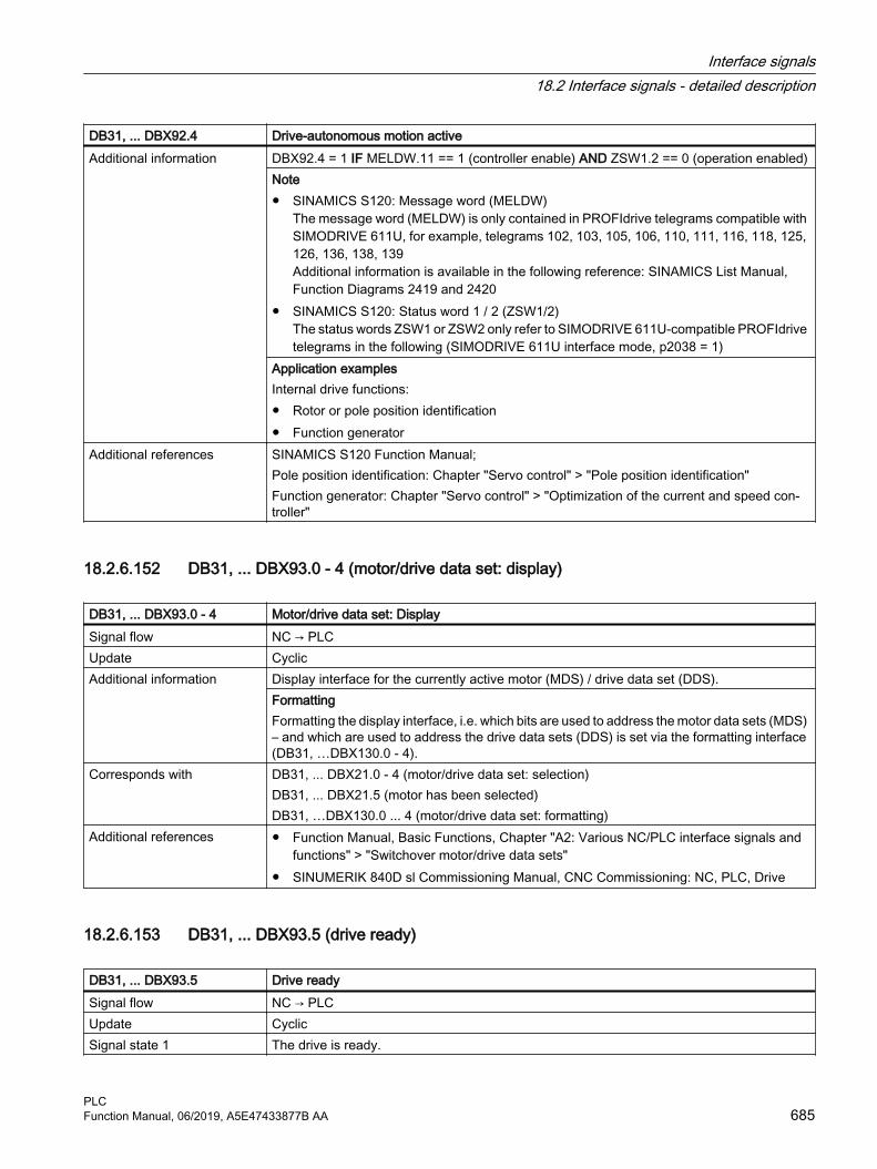
DB31, ... DBX92.4 Drive-autonomous motion activeAdditional information DBX92.4 = 1 IF MELDW.11 == 1 (controller enable) AND ZSW1.2 == 0 (operation enabled)
Note● SINAMICS S120: Message word (MELDW)
The message word (MELDW) is only contained in PROFIdrive telegrams compatible with SIMODRIVE 611U, for example, telegrams 102, 103, 105, 106, 110, 111, 116, 118, 125, 126, 136, 138, 139Additional information is available in the following reference: SINAMICS List Manual, Function Diagrams 2419 and 2420
● SINAMICS S120: Status word 1 / 2 (ZSW1/2)The status words ZSW1 or ZSW2 only refer to SIMODRIVE 611U-compatible PROFIdrive telegrams in the following (SIMODRIVE 611U interface mode, p2038 = 1)
Application examplesInternal drive functions:● Rotor or pole position identification● Function generator
Additional references SINAMICS S120 Function Manual; Pole position identification: Chapter "Servo control" > "Pole position identification"Function generator: Chapter "Servo control" > "Optimization of the current and speed con‐troller"
18.2.6.152 DB31, ... DBX93.0 - 4 (motor/drive data set: display)
DB31, ... DBX93.0 - 4 Motor/drive data set: DisplaySignal flow NC → PLCUpdate CyclicAdditional information Display interface for the currently active motor (MDS) / drive data set (DDS).
FormattingFormatting the display interface, i.e. which bits are used to address the motor data sets (MDS) – and which are used to address the drive data sets (DDS) is set via the formatting interface (DB31, …DBX130.0 - 4).
Corresponds with DB31, ... DBX21.0 - 4 (motor/drive data set: selection)DB31, ... DBX21.5 (motor has been selected)DB31, …DBX130.0 ... 4 (motor/drive data set: formatting)
Additional references ● Function Manual, Basic Functions, Chapter "A2: Various NC/PLC interface signals and functions" > "Switchover motor/drive data sets"
● SINUMERIK 840D sl Commissioning Manual, CNC Commissioning: NC, PLC, Drive
18.2.6.153 DB31, ... DBX93.5 (drive ready)
DB31, ... DBX93.5 Drive readySignal flow NC → PLCUpdate CyclicSignal state 1 The drive is ready.
Interface signals18.2 Interface signals - detailed description
PLCFunction Manual, 06/2019, A5E47433877B AA 685

DB31, ... DBX93.5 Drive readySignal state 0 The drive is not ready.
If the signal is reset while operational, the drive is stopped (pulse inhibit or fast stop). When powering-up, the pulses are still inhibited (canceled). In addition, the following interface sig‐nals are reset:● DB10, DBX108.6 = 0 (drive ready)● DB31, ... DBX61.7 = 0 (current controller active)● DB31, ... DBX61.6 = 0 (speed controller active)
Additional information Interface signal: DB31, ... DBX93.5 = drive: MELDW.12Note● SINAMICS S120: Message word (MELDW)
The message word (MELDW) is only contained in PROFIdrive telegrams compatible with SIMODRIVE 611U, for example, telegrams 102, 103, 105, 106, 110, 111, 116, 118, 125, 126, 136, 138, 139Additional information is available in the following reference: SINAMICS List Manual, Function Diagrams 2419 and 2420
● SINAMICS S120: Status word 1 / 2 (ZSW1/2)The status words ZSW1 or ZSW2 only refer to SIMODRIVE 611U-compatible PROFIdrive telegrams in the following (SIMODRIVE 611U interface mode, p2038 = 1)
Corresponds with DB10, DBX108.6 (Drives ready)DB31, ... DBX61.7 (current controller active)DB31, ... DBX61.6 (speed controller active)
Additional references ● Function Manual, Basic Functions, Chapter "A2: Various NC/PLC interface signals and functions" > "Switchover motor/drive data sets"
● SINUMERIK 840D sl Commissioning Manual, CNC Commissioning: NC, PLC, Drive● SINAMICS S120/S150 List Manual
18.2.6.154 DB31, ... DBX93.6 (integrator disable, speed controller)
DB31, ... DBX93.6 Integrator disable, speed controllerSignal flow NC → PLCUpdate CyclicSignal state 1 The integrator of the speed controller in the drive is inhibited.
The speed controller functions as a P controller.Signal state 0 The integrator of the speed controller in the drive is not disabled.
The speed controller functions as a PI controller.Corresponds with DB31, ... DBX21.6 (integrator disable, speed controller)Additional references SINUMERIK 840D sl Commissioning Manual, CNC Commissioning: NC, PLC, Drive
Interface signals18.2 Interface signals - detailed description
PLC686 Function Manual, 06/2019, A5E47433877B AA

18.2.6.155 DB31, ... DBX93.7 (pulses enabled)
DB31, ... DBX93.7 Pulses enabledSignal flow NC → PLCUpdate CyclicSignal state 1 The drive pulses are enabled.Signal state 0 The drive pulses are not enabled.
● DB31, ... DBX61.7 = 0 (current controller active)● DB31, ... DBX61.6 = 0 (speed controller active)● DB31, ... DBX61.5 = 0 (position controller active)
Additional information DB31, ... DBX93.7 = MELDW.13Note● SINAMICS S120: Message word (MELDW)
The message word (MELDW) is only contained in PROFIdrive telegrams compatible with SIMODRIVE 611U, for example, telegrams 102, 103, 105, 106, 110, 111, 116, 118, 125, 126, 136, 138, 139Additional information is available in the following reference: SINAMICS List Manual, Function Diagrams 2419 and 2420
● SINAMICS S120: Status word 1 / 2 (ZSW1/2)The status words ZSW1 or ZSW2 only refer to SIMODRIVE 611U-compatible PROFIdrive telegrams in the following (SIMODRIVE 611U interface mode, p2038 = 1)
Corresponds with DB31, ... DBX21.7 (pulse enable)Additional references SINUMERIK 840D sl Commissioning Manual, CNC Commissioning: NC, PLC, Drive
18.2.6.156 DB31, ... DBX94.0 (motor temperature prewarning)
DB31, ... DBX94.0 Motor temperature prewarningSignal flow NC → PLCUpdate CyclicSignal state 1 The motor temperature has exceeded the warning threshold (p0604) configured in the drive.
NoteIf the motor temperature remains too high for longer than the parameterized time (p0606), a fault is output, the drive is stopped and the pulse enable removed.If the motor temperature falls below the warning threshold (p0604) again before the time has expired (p0606), the interface signal is reset.
Signal state 0 The motor temperature is below the warning threshold (p0604).Additional information The actual motor temperature is displayed on the user interface at:
Operating area "Diagnostics" > "Service display: Axis/spindle"Corresponds with DB31, ... DBX94.1 (heat sink temperature prewarning)
Interface signals18.2 Interface signals - detailed description
PLCFunction Manual, 06/2019, A5E47433877B AA 687

18.2.6.157 DB31, ... DBX94.1 (heat sink temperature prewarning)
DB31, ... DBX94.1 Heat sink temperature prewarningSignal flow NC → PLCUpdate CyclicSignal state 1 The heat sink temperature of the power semiconductors has exceeded the parameterized
warning threshold (p0294).NoteThe parameterized reaction (p0290) is performed in the drive. If the temperature violation remains, a fault is output after approx. 20 s, the drive is stopped and the pulse enable removed.
Signal state 0 The heat sink temperature is below the warning threshold.Additional information The interface signals DB31, ... DBX94.0 and .1 are derived from the following signals of the
cyclic drive telegram:● Case 1: Temperature alarm in the message word
– DB31, ... DBX94.0 ≙ MELDW, bit 6 (no motor overtemperature warning)– DB31, ... DBX94.1 ≙ MELDW, bit 7 (no thermal overload in power unit warning)
● Case 2: Alarm of alarm class B (interface mode "SIMODRIVE 611U", p2038 = 1)DB31, ... DBX94.0 == 1 and DBX94.1 == 1, if the following applies:cyclic drive telegram, ZSW1: bit 11 == 0 and 12 == 1 (alarm class B)
The interface signals are derived from the alarm of alarm class B if there is no specific infor‐mation from the message word.An alarm is displayed. Alarm number = 200.000 + alarm value (r2124)Note● SINAMICS S120: Message word (MELDW)
The message word (MELDW) is only contained in PROFIdrive telegrams compatible with SIMODRIVE 611U, for example, telegrams 102, 103, 105, 106, 110, 111, 116, 118, 125, 126, 136, 138, 139Additional information is available in the following reference: SINAMICS List Manual, Function Diagrams 2419 and 2420
● SINAMICS S120: Status word 1 / 2 (ZSW1/2)The status words ZSW1 or ZSW2 only refer to SIMODRIVE 611U-compatible PROFIdrive telegrams in the following (SIMODRIVE 611U interface mode, p2038 = 1)
Additional references ● S120 Commissioning Manual, Chapter "Commissioning" > "Temperature sensors for SINAMICS components"
● S120 Function Manual, Chapter "Monitoring and protection functions"● S120 List Manual
– MELDW, bit 6 ≙ BO: r2135.14 → function diagram: 2548, 8016– MELDW, bit 7 ≙ BO: r2135.15 → function diagram: 2548, 2452, 2456, 8016
● SINUMERIK Diagnostics Manual
18.2.6.158 DB31, ... DBX94.2 (run-up completed)
DB31, ... DBX94.2 Power up completedSignal flow NC → PLCUpdate Cyclic
Interface signals18.2 Interface signals - detailed description
PLC688 Function Manual, 06/2019, A5E47433877B AA

DB31, ... DBX94.2 Power up completedSignal state 1 After a new speed setpoint, the speed actual value has reached the speed tolerance band
defined using drive parameter p2164, and has not left it for the time specified in p2166.Any subsequent speed fluctuations, also outside the tolerance band, e.g. due to load changes, will not affect the interface signal.
Signal state 0 The power up operation is still active after the speed setpoint has been changed.Corresponds with DB31, ... DBX94.6 ("nact = nset")
DB31, ... DBX94.3 ("|MD| = Mdx")Additional references ● SINUMERIK 840D sl Commissioning Manual, CNC Commissioning: NC, PLC, Drive
● SINAMICS S120 List Manual
18.2.6.159 DB31, ... DBX94.3 (|Md| < Mdx)
DB31, ... DBX94.3 |Md| < Mdx
Signal flow NC → PLCUpdate CyclicSignal state 1 The current torque utilization is below the torque utilization threshold (torque threshold 2,
p2194).The power up operation has been completed, the drive is in the steady state and the torque setpoint |Md| drive does not exceed the threshold torque Mdx. The torque threshold characteristic is speed-dependent.During the power up operation, DB31, ... DBX94.3 (|Md|< Mdx) == 1. The interface signal is not updated until the power has been completed (DB31, ... DBX94.2 == 1) and the signal inter‐locking time for the threshold torque has expired.
Signal state 0 The torque setpoint |Md| is higher than the threshold torque Mdx. A motor overload can be determined via the interface signal. An appropriate response can then be initiated in the PLC user program.
Additional information DB31, ... DBX94.3 = MELDW.1Note● SINAMICS S120: Message word (MELDW)
The message word (MELDW) is only contained in PROFIdrive telegrams compatible with SIMODRIVE 611U, for example, telegrams 102, 103, 105, 106, 110, 111, 116, 118, 125, 126, 136, 138, 139Additional information is available in the following reference: SINAMICS List Manual, Function Diagrams 2419 and 2420
● SINAMICS S120: Status word 1 / 2 (ZSW1/2)The status words ZSW1 or ZSW2 only refer to SIMODRIVE 611U-compatible PROFIdrive telegrams in the following (SIMODRIVE 611U interface mode, p2038 = 1)
Additional references ● SINUMERIK 840D sl Commissioning Manual, CNC Commissioning: NC, PLC, Drive● SIMATIC S120 List Manual
Interface signals18.2 Interface signals - detailed description
PLCFunction Manual, 06/2019, A5E47433877B AA 689

18.2.6.160 DB31, ... DBX94.4 (|nact| < nmin)
DB31, ... DBX94.4 |nact| < nmin
Signal flow NC → PLCUpdate CyclicSignal state 1 The actual speed value nact is less than nmin (speed threshold value 3, p2161).Signal state 0 The actual speed value is greater than the minimum threshold speed nmin.Additional information DB31, ... DBX94.4 = MELDW.2
Note● SINAMICS S120: Message word (MELDW)
The message word (MELDW) is only contained in PROFIdrive telegrams compatible with SIMODRIVE 611U, for example, telegrams 102, 103, 105, 106, 110, 111, 116, 118, 125, 126, 136, 138, 139Additional information is available in the following reference: SINAMICS List Manual, Function Diagrams 2419 and 2420
● SINAMICS S120: Status word 1 / 2 (ZSW1/2)The status words ZSW1 or ZSW2 only refer to SIMODRIVE 611U-compatible PROFIdrive telegrams in the following (SIMODRIVE 611U interface mode, p2038 = 1)
Additional references SINUMERIK 840D sl Commissioning Manual, CNC Commissioning: NC, PLC, Drive
18.2.6.161 DB31, ... DBX94.5 (|nact| < nx)
DB31, ... DBX94.5 |nact| < nx
Signal flow NC → PLCUpdate CyclicSignal state 1 The actual speed value nact is less than nx (speed threshold value 2, p2155).Signal state 0 The actual speed value nact is greater than the threshold speed nx.Additional information DB31, ... DBX94.5 = MELDW.3
Note● SINAMICS S120: Message word (MELDW)
The message word (MELDW) is only contained in PROFIdrive telegrams compatible with SIMODRIVE 611U, for example, telegrams 102, 103, 105, 106, 110, 111, 116, 118, 125, 126, 136, 138, 139Additional information is available in the following reference: SINAMICS List Manual, Function Diagrams 2419 and 2420
● SINAMICS S120: Status word 1 / 2 (ZSW1/2)The status words ZSW1 or ZSW2 only refer to SIMODRIVE 611U-compatible PROFIdrive telegrams in the following (SIMODRIVE 611U interface mode, p2038 = 1)
Additional references SINUMERIK 840D sl Commissioning Manual, CNC Commissioning: NC, PLC, Drive
Interface signals18.2 Interface signals - detailed description
PLC690 Function Manual, 06/2019, A5E47433877B AA

18.2.6.162 DB31, ... DBX94.6 (nact = nset)
DB31, ... DBX94.6 nact = nset
Signal flow NC → PLCUpdate CyclicSignal state 1 The actual speed value is at least the parameterized time (switch-on delay n_act = n_set,
p2167) within the tolerance band around the speed setpoint (speed threshold value 4, p2163). Signal state 0 The actual speed value is outside the tolerance band around the speed setpoint (speed
threshold value 4, p2163).Additional references SINUMERIK 840D sl Commissioning Manual, CNC Commissioning: NC, PLC, Drive
18.2.6.163 DB31, ... DBX94.7 (variable signaling function)
DB31, ... DBX94.7 Variable signaling functionSignal flow NC → PLCUpdate CyclicSignal state 1 The parameterized drive variable has exceeded the specified threshold value, including hys‐
teresis.Signal state 0 The parameterized drive variable has fallen below the specified threshold value, including
hysteresis.Additional information Using the "Variable signaling" function, BICO interconnections and parameters which have
the attribute traceable can be monitored in the drive.DB31, ... DBX94.7 = MELDW.5Note● SINAMICS S120: Message word (MELDW)
The message word (MELDW) is only contained in PROFIdrive telegrams compatible with SIMODRIVE 611U, for example, telegrams 102, 103, 105, 106, 110, 111, 116, 118, 125, 126, 136, 138, 139Additional information is available in the following reference: SINAMICS List Manual, Function Diagrams 2419 and 2420
● SINAMICS S120: Status word 1 / 2 (ZSW1/2)The status words ZSW1 or ZSW2 only refer to SIMODRIVE 611U-compatible PROFIdrive telegrams in the following (SIMODRIVE 611U interface mode, p2038 = 1)
Additional references SINAMICS S120 Function Manual, Chapter "Servo control" > "Variable signaling function"
18.2.6.164 DB31, ... DBX95.1 (ESR: DC link undervoltage)
DB31, ... DBX95.1 ESR: DC link undervoltageSignal flow NC → PLCUpdate CyclicSignal state 1 The drive signals that the DC link voltage UDC link is less than the lower DC link voltage thresh‐
old set with parameter p1248.Signal state 0 The drive signals that the DC link voltage UDC link is greater than they lower DC link voltage
threshold set with parameter p1248.
Interface signals18.2 Interface signals - detailed description
PLCFunction Manual, 06/2019, A5E47433877B AA 691

DB31, ... DBX95.1 ESR: DC link undervoltageAdditional information Note
The PLC user program can initiate measures in order to safely end machining and/or to buffer the DC link voltage, e.g. initiate a drive-based and/or control-managed extended stop and retract (ESR).
Corresponds with Drive parameter p1248 (lower DC link voltage threshold)Drive telegram MELDW.Bit 4
Additional references SINUMERIK 840D sl Commissioning Manual, CNC Commissioning: NC, PLC, drive
18.2.6.165 DB31, ... DBX95.2 (ESR: Response initiated or generator operation active)
DB31, ... DBX95.2 ESR: Response initiated or generator operation activeSignal flow NC → PLCUpdate CyclicSignal state 1 The drive signals that the configured ESR response has been initiated or generator operation
is active.Signal state 0 The drive signals that neither the configured ESR response has been initiated nor that gen‐
erator operation is active.Corresponds with Drive telegram MELDW.Bit 9Additional references SINUMERIK 840D sl Commissioning Manual, CNC Commissioning: NC, PLC, drive
18.2.6.166 DB31, … DBX95.3 (generator operation minimum speed fallen below)
DB31, ... DBX95.3 ESR: Generator operation - minimum speed fallen belowSignal flow NC → PLCUpdate CyclicSignal state 1 The axis is parameterized as generator axis. The drive signals that the actual speed is less
than the minimum speed set using parameter p2161 (speed threshold value 3).Signal state 0 The axis is parameterized as generator axis. The drive signals that the actual speed is greater
than the minimum speed set using parameter p2161 (speed threshold value 3).Additional information The PLC user program can initiate measures in order to safely end machining and/or to buffer
the DC link voltage, e.g. initiate a drive-based and/or control-managed extended stop and retract (ESR).
Corresponds with Drive parameter p2161 (speed threshold value 3)Drive telegram MELDW.Bit2
Additional references SINUMERIK 840D sl Commissioning Manual, CNC Commissioning: NC, PLC, drive
18.2.6.167 DB31, ... DBX95.7 (alarm of alarm class C is active)
DB31, ... DBX95.7 Alarm of alarm class C is activeSignal flow NC → PLCUpdate CyclicSignal state 1 The drive signals that an alarm of alarm class C is active.
Interface signals18.2 Interface signals - detailed description
PLC692 Function Manual, 06/2019, A5E47433877B AA
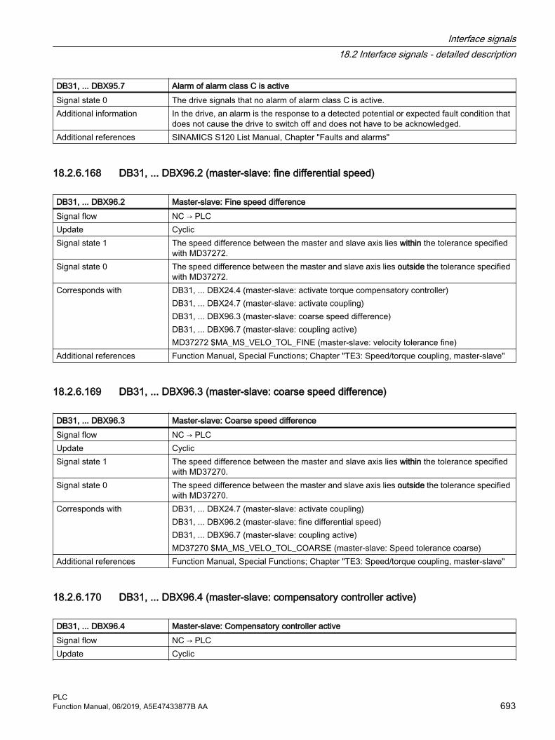
DB31, ... DBX95.7 Alarm of alarm class C is activeSignal state 0 The drive signals that no alarm of alarm class C is active.Additional information In the drive, an alarm is the response to a detected potential or expected fault condition that
does not cause the drive to switch off and does not have to be acknowledged.Additional references SINAMICS S120 List Manual, Chapter "Faults and alarms"
18.2.6.168 DB31, ... DBX96.2 (master-slave: fine differential speed)
DB31, ... DBX96.2 Master-slave: Fine speed differenceSignal flow NC → PLCUpdate CyclicSignal state 1 The speed difference between the master and slave axis lies within the tolerance specified
with MD37272.Signal state 0 The speed difference between the master and slave axis lies outside the tolerance specified
with MD37272.Corresponds with DB31, ... DBX24.4 (master-slave: activate torque compensatory controller)
DB31, ... DBX24.7 (master-slave: activate coupling)DB31, ... DBX96.3 (master-slave: coarse speed difference)DB31, ... DBX96.7 (master-slave: coupling active)MD37272 $MA_MS_VELO_TOL_FINE (master-slave: velocity tolerance fine)
Additional references Function Manual, Special Functions; Chapter "TE3: Speed/torque coupling, master-slave"
18.2.6.169 DB31, ... DBX96.3 (master-slave: coarse speed difference)
DB31, ... DBX96.3 Master-slave: Coarse speed differenceSignal flow NC → PLCUpdate CyclicSignal state 1 The speed difference between the master and slave axis lies within the tolerance specified
with MD37270.Signal state 0 The speed difference between the master and slave axis lies outside the tolerance specified
with MD37270.Corresponds with DB31, ... DBX24.7 (master-slave: activate coupling)
DB31, ... DBX96.2 (master-slave: fine differential speed)DB31, ... DBX96.7 (master-slave: coupling active)MD37270 $MA_MS_VELO_TOL_COARSE (master-slave: Speed tolerance coarse)
Additional references Function Manual, Special Functions; Chapter "TE3: Speed/torque coupling, master-slave"
18.2.6.170 DB31, ... DBX96.4 (master-slave: compensatory controller active)
DB31, ... DBX96.4 Master-slave: Compensatory controller activeSignal flow NC → PLCUpdate Cyclic
Interface signals18.2 Interface signals - detailed description
PLCFunction Manual, 06/2019, A5E47433877B AA 693
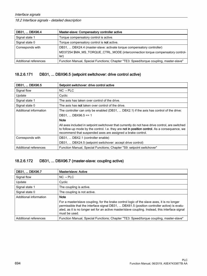
DB31, ... DBX96.4 Master-slave: Compensatory controller activeSignal state 1 Torque compensatory control is active.Signal state 0 Torque compensatory control is not active. Corresponds with DB31, ... DBX24.4 (master-slave: activate torque compensatory controller)
MD37254 $MA_MS_TORQUE_CTRL_MODE (interconnection torque compensatory control‐ler)
Additional references Function Manual, Special Functions; Chapter "TE3: Speed/torque coupling, master-slave"
18.2.6.171 DB31, ... DBX96.5 (setpoint switchover: drive control active)
DB31, ... DBX96.5 Setpoint switchover: drive control activeSignal flow NC → PLCUpdate CyclicSignal state 1 The axis has taken over control of the drive.Signal state 0 The axis has not taken over control of the drive.Additional information The controller can only be enabled (DB31, ... DBX2.1) if the axis has control of the drive:
DB31, ... DBX96.5 == 1NoteAll axes included in setpoint switchover that currently do not have drive control, are switched to follow-up mode by the control. I.e. they are not in position control. As a consequence, we recommend that suspended axes are assigned a brake control.
Corresponds with DB31, ... DBX2.1 (controller enable)DB31, ... DBX24.5 (setpoint switchover: accept drive control)
Additional references Function Manual, Special Functions; Chapter "S9: setpoint switchover"
18.2.6.172 DB31, ... DBX96.7 (master-slave: coupling active)
DB31, ... DBX96.7 Master/slave: ActiveSignal flow NC → PLCUpdate CyclicSignal state 1 The coupling is active.Signal state 0 The coupling is not active. Additional information Note
For a master/slave coupling, for the brake control logic of the slave axes, it is no longer permissible that the interface signal DB31, ... DBX61.5 (position controller active) is evalu‐ated, as it is no longer set for an active master/slave coupling. Instead, this interface signal must be used.
Additional references Function Manual, Special Functions; Chapter "TE3: Speed/torque coupling, master-slave"
Interface signals18.2 Interface signals - detailed description
PLC694 Function Manual, 06/2019, A5E47433877B AA

18.2.6.173 DB31, ... DBX97.0 (MCS coupling: slave axis)
DB31, …DBX97.0 MCS coupling: Following axisSignal flow NC → PLCUpdate Job-controlledSignal state 1 The axis is a following axis:Signal state 0 The axis is not a following axis:Corresponds with DB31, …DBX24.2 (MCS coupling: deactivate or do not permit)
DB31, ... DBX24.3 (MCS coupling: activate collision protection)DB31, ... DBX66.0 (MCS coupling: collision protection active)DB31, ... DBX97.0 (MCS coupling: slave axis)DB31, … DBX97.1 (MCS coupling: coupling active)DB31, ... DBX97.2 (MCS coupling: mirroring active)DB31, ... DBX97.3 (MCS coupling: offset change)
Additional references Function Manual, Special Functions; Chapter "TE6: MCS coupling"
18.2.6.174 DB31, … DBX97.1 (MCS coupling: coupling active)
DB31, …DBX97.1 MCS coupling: Coupling activeSignal flow NC → PLCUpdate Job-controlledSignal state 1 The coupling is active.Signal state 0 The coupling is not active.Corresponds with DB31, …DBX24.2 (MCS coupling: deactivate or do not permit)
DB31, ... DBX24.3 (MCS coupling: activate collision protection)DB31, ... DBX66.0 (MCS coupling: collision protection active)DB31, ... DBX97.0 (MCS coupling: slave axis)DB31, … DBX97.1 (MCS coupling: coupling active)DB31, ... DBX97.2 (MCS coupling: mirroring active)DB31, ... DBX97.3 (MCS coupling: offset change)
Additional references Function Manual, Special Functions; Chapter "TE6: MCS coupling"
18.2.6.175 DB31, ... DBX97.2 (MCS coupling: mirroring active)
DB31, …DBX97.2 MCS coupling: Mirroring activeSignal flow NC → PLCUpdate Job-controlledSignal state 1 The "mirroring" function is active.Signal state 0 The "mirroring" function is not active.Additional information Displayed only for the CC_slave axis.
Interface signals18.2 Interface signals - detailed description
PLCFunction Manual, 06/2019, A5E47433877B AA 695

DB31, …DBX97.2 MCS coupling: Mirroring activeCorresponds with DB31, …DBX24.2 (MCS coupling: deactivate or do not permit)
DB31, ... DBX24.3 (MCS coupling: activate collision protection)DB31, ... DBX66.0 (MCS coupling: collision protection active)DB31, ... DBX97.0 (MCS coupling: slave axis)DB31, … DBX97.1 (MCS coupling: coupling active)DB31, ... DBX97.2 (MCS coupling: mirroring active)DB31, ... DBX97.3 (MCS coupling: offset change)
Additional references Function Manual, Special Functions; Chapter "TE6: MCS coupling"
18.2.6.176 DB31, ... DBX97.3 (MCS coupling: offset change)
DB31, …DBX97.3 MCS coupling: Offset changeSignal flow NC → PLCUpdate Job-controlledSignal state 1 The offset has changed since activation instant.Signal state 0 The offset has not changed since the activation instant.Additional information The interface signal is set, if, for an active 1:1 coupling, the offset saved at the activation
instant has changed.NoteIn the reset phase, the interface signal is not set.
Corresponds with DB31, …DBX24.2 (MCS coupling: deactivate or do not permit)DB31, ... DBX24.3 (MCS coupling: activate collision protection)DB31, ... DBX66.0 (MCS coupling: collision protection active)DB31, ... DBX97.0 (MCS coupling: slave axis)DB31, … DBX97.1 (MCS coupling: coupling active)DB31, ... DBX97.2 (MCS coupling: mirroring active)DB31, ... DBX97.3 (MCS coupling: offset change)
Additional references Function Manual, Special Functions; Chapter "TE6: MCS coupling"
18.2.6.177 DB31, ... DBX98.0 (fine synchronous operation)
DB31, ... DBX98.0 Synchronous operation fineSignal flow NC → PLCUpdate CyclicSignal state 1 Synchronous spindle coupling: The position deviation or velocity difference between the fol‐
lowing spindle and its leading spindle is within the "Fine synchronous operation" tolerance band.
Signal state 0 Synchronous spindle coupling: The position deviation or velocity difference between the fol‐lowing spindle and its leading spindle is not within the "Fine synchronous operation" tolerance band.
Interface signals18.2 Interface signals - detailed description
PLC696 Function Manual, 06/2019, A5E47433877B AA

DB31, ... DBX98.0 Synchronous operation fineAdditional information Note
The signal is relevant only for the following spindle in synchronous operation.Application exampleClamping of the workpiece in the following spindle at the transfer from the leading spindle: The clamping of the workpiece is only initiated by the PLC user program when the spindles are operating in adequate synchronism.
Corresponds with DB31, ... DBX84.4 (active spindle operating mode: Synchronous operation)MD37210 $MA_COUPLE_POS_TOL_FINE (threshold value for "fine synchronism")MD37230 $MA_COUPLE_VELO_TOL_FINE ("fine" speed tolerance)
Additional references Function Manual, Extended Functions; Chapter "S3: Synchronous spindle"
18.2.6.178 DB31, ... DBX98.1 (coarse synchronous operation)
DB31, ... DBX98.1 Synchronous operation, coarseSignal flow NC → PLCUpdate CyclicSignal state 1 Synchronous spindle coupling: The position deviation or velocity difference between the fol‐
lowing spindle and its leading spindle is within the "Coarse synchronous operation" tolerance band.
Signal state 0 Synchronous spindle coupling: The position deviation or velocity difference between the fol‐lowing spindle and its leading spindle is not within the "Coarse synchronous operation" tol‐erance band.
Additional information NoteThe signal is relevant only for the following spindle in synchronous operation.Application exampleClamping of the workpiece in the following spindle at the transfer from the leading spindle: The clamping of the workpiece is only initiated by the PLC user program when the spindles are operating in adequate synchronism.
Corresponds with DB31, ... DBX84.4 (active spindle operating mode: Synchronous operation)MD37200 $MA_COUPLE_POS_TOL_COARSE (threshold value for "coarse synchronism")MD37220 $MA_COUPLE_VELO_TOL_COARSE ("coarse" speed tolerance)
Additional references Function Manual, Extended Functions; Chapter "S3: Synchronous spindle"
18.2.6.179 DB31, ... DBX98.2 (actual value coupling)
DB31, ... DBX98.2 Actual value couplingSignal flow NC → PLCUpdate CyclicSignal state 1 Synchronous spindle coupling: Actual value coupling activeSignal state 0 Synchronous spindle coupling: Setpoint coupling active
Interface signals18.2 Interface signals - detailed description
PLCFunction Manual, 06/2019, A5E47433877B AA 697

DB31, ... DBX98.2 Actual value couplingAdditional information Note
The signal is relevant only for the active following spindle in synchronous operation.Special cases or errorsIf faults occur on the following spindle that cause a withdrawal of the "Controller enable" for the following spindle, under certain circumstances, the control may exchange the coupling rela‐tionship of the following spindle and leading spindle and switch to actual value coupling.
Corresponds with DB31, ... DBX84.4 (active spindle operating mode: Synchronous operation)MD21310 $MC_COUPLING_MODE_1 (coupling type in synchr. spindle oper.)
Additional references Function Manual, Extended Functions; Chapter "S3: Synchronous spindle"
18.2.6.180 DB31, ... DBX98.4 (overlaid movement)
DB31, ... DBX98.4 Overlaid motionSignal flow NC → PLCUpdate CyclicSignal state 1 Synchronous spindle coupling: The following spindle executes an additional motion compo‐
nent that is superimposed on the motion from the coupling with the leading spindle.Signal state 0 Synchronous spindle coupling: The following spindle does not traverse through any additional
motion component - or this has been completed.Additional information Note
The signal is relevant only for the following spindle in synchronous operation.Application examplesExample for superimposed motion of the following spindle:● Activating the synchronous mode with a defined angular offset between the following
spindle and leading spindle.● Activating the synchronous mode for rotating leading spindle.● Changing the ratio while the synchronous mode is active.● Entering a new defined angular offset when the synchronous mode is active.● Traversing the following spindle in the JOG mode with the traversing keys "Plus" / "Minus"
or the handwheel with synchronous operation activeCorresponds with DB31, ... DBX84.4 (active spindle operating mode: Synchronous operation)Additional references Function Manual, Extended Functions; Chapter "S3: Synchronous spindle"
18.2.6.181 DB31, ... DBX98.5 (speed alarm threshold reached)
DB31, ... DBX98.5 Velocity alarm threshold reachedSignal flow NC → PLCUpdate CyclicSignal state 1 Electronic gearbox (EG): The velocity of the following axis has reached or exceeded the
parameterized velocity alarm threshold.Signal state 0 Electronic gearbox (EG): The velocity of the following axis is below the parameterized velocity
alarm threshold.
Interface signals18.2 Interface signals - detailed description
PLC698 Function Manual, 06/2019, A5E47433877B AA
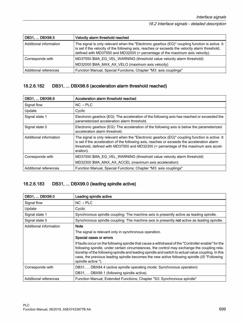
DB31, ... DBX98.5 Velocity alarm threshold reachedAdditional information The signal is only relevant when the "Electronic gearbox (EG)" coupling function is active. It
is set if the velocity of the following axis, reaches or exceeds the velocity alarm threshold, defined with MD37550 and MD32000 (= percentage of the maximum axis velocity).
Corresponds with MD37550 $MA_EG_VEL_WARNING (threshold value velocity alarm threshold)MD32000 $MA_MAX_AX_VELO (maximum axis velocity)
Additional references Function Manual, Special Functions; Chapter "M3: axis couplings"
18.2.6.182 DB31, ... DBX98.6 (acceleration alarm threshold reached)
DB31, ... DBX98.6 Acceleration alarm threshold reachedSignal flow NC → PLCUpdate CyclicSignal state 1 Electronic gearbox (EG): The acceleration of the following axis has reached or exceeded the
parameterized acceleration alarm threshold.Signal state 0 Electronic gearbox (EG): The acceleration of the following axis is below the parameterized
acceleration alarm threshold.Additional information The signal is only relevant when the "Electronic gearbox (EG)" coupling function is active. It
is set if the acceleration of the following axis, reaches or exceeds the acceleration alarm threshold, defined with MD37550 and MD32300 (= percentage of the maximum axis accel‐eration).
Corresponds with MD37550 $MA_EG_VEL_WARNING (threshold value velocity alarm threshold)MD32300 $MA_MAX_AX_ACCEL (maximum axis acceleration)
Additional references Function Manual, Special Functions; Chapter "M3: axis couplings"
18.2.6.183 DB31, ... DBX99.0 (leading spindle active)
DB31, ... DBX99.0 Leading spindle activeSignal flow NC → PLCUpdate CyclicSignal state 1 Synchronous spindle coupling: The machine axis is presently active as leading spindle.Signal state 0 Synchronous spindle coupling: The machine axis is presently not active as leading spindle.Additional information Note
The signal is relevant only in synchronous operation.Special cases or errorsIf faults occur on the following spindle that cause a withdrawal of the "Controller enable" for the following spindle, under certain circumstances, the control may exchange the coupling rela‐tionship of the following spindle and leading spindle and switch to actual value coupling. In this case, the previous leading spindle becomes the new active following spindle (IS "Following spindle active ").
Corresponds with DB31, ... DBX84.4 (active spindle operating mode: Synchronous operation)DB31, ... DBX99.1 (following spindle active)
Additional references Function Manual, Extended Functions; Chapter "S3: Synchronous spindle"
Interface signals18.2 Interface signals - detailed description
PLCFunction Manual, 06/2019, A5E47433877B AA 699

18.2.6.184 DB31, ... DBX99.1 (following spindle active)
DB31, ... DBX99.1 Following spindle activeSignal flow NC → PLCUpdate CyclicSignal state 1 Synchronous spindle coupling: The machine axis is currently being operated as a following
spindle.Signal state 0 Synchronous spindle coupling: The machine axis is currently not being operated as a follow‐
ing spindle.Additional information For DB31, ... DBX99.1 == 1, the following spindle follows the motion of the leading spindle
corresponding to the ratio.NoteThe signal is relevant only in synchronous operation.Special cases or errorsIf faults occur on the following spindle that cause a withdrawal of the "Controller enable" for the following spindle, under certain circumstances, the control may exchange the coupling rela‐tionship of the following spindle and leading spindle and switch to actual value coupling.
Corresponds with DB31, ... DBX84.4 (active spindle operating mode: Synchronous operation)DB31, ... DBX99.0 (leading spindle active)
Additional references Function Manual, Extended Functions; Chapter "S3: Synchronous spindle"
18.2.6.185 DB31, ... DBX99.3 (axis accelerates)
DB31, ... DBX99.3 Axis acceleratesSignal flow NC → PLCUpdate CyclicSignal state 1 Electronic gearbox (EG): The acceleration of the following axis has reached or exceeded the
parameterized acceleration level, at which the acceleration of the axis is displayed.Signal state 0 Electronic gearbox (EG): The acceleration of the following axis lies below the parameterized
acceleration level, at which the acceleration of the axis is displayed.Additional information The signal is only relevant when the "Electronic gearbox (EG)" coupling function is active. It
is set if the acceleration of the following axis, reaches or exceeds the acceleration alarm value, defined with MD37560 and MD32300.
Corresponds with MD37560 $MA_EG_ACC_TOL (threshold value for "Axis accelerates")MD32300 $MA_MAX_AX_ACCEL (maximum axis acceleration)
Additional references Function Manual, Special Functions; Chapter "M3: axis couplings"
18.2.6.186 DB31, ... DBX100.2 (oscillation reversal from external active)
DB31, ... DBX100.2 External oscillation reversal activeSignal flow NC → PLCUpdate CyclicSignal state 1 The braking phase after "oscillation reversal from external" is active.Signal state 0 The braking phase after "oscillation reversal from external" is not active.
Interface signals18.2 Interface signals - detailed description
PLC700 Function Manual, 06/2019, A5E47433877B AA

DB31, ... DBX100.2 External oscillation reversal activeCorresponds with DB31, ... DBX28.0 (oscillation reversal from external)Additional references Function Manual, Extended Functions; Chapter "P5: Oscillation"
18.2.6.187 DB31, ... DBX100.3 (oscillation cannot be started)
DB31, ... DBX100.3 Oscillation cannot be startedSignal flow NC → PLCUpdate CyclicSignal state 1 The oscillation axis cannot be started.Signal state 0 Oscillation motion cannot be started.Additional information This signal is set if there is a programming error, for example.
NoteThis state can also occur if axis was already traversed.
Additional references Function Manual, Extended Functions; Chapter "P5: Oscillation"
18.2.6.188 DB31, ... DBX100.4 (error during oscillation)
DB31, ... DBX100.4 Error during oscillationSignal flow NC → PLCSignal state 1 Oscillation motion was canceled as an error occurred while oscillating.Signal state 0 Oscillation is error free.Additional references Function Manual, Extended Functions; Chapter "P5: Oscillation"
18.2.6.189 DB31, …DBX100.5 (sparking-out active)
DB31, ... DBX100.5 Sparking-out activeSignal flow NC → PLCUpdate CyclicSignal state 1 The axis executes sparking-out strokes.Signal state 0 The axis is presently not executing any sparking-out strokes.Corresponds with DB31, ... DBX100.7 (oscillation active)Additional references Function Manual, Extended Functions; Chapter "P5: Oscillation"
18.2.6.190 DB31, ... DBX100.6 (oscillation active)
DB31, ... DBX100.6 Oscillation activeSignal flow NC → PLCUpdate CyclicSignal state 1 The axis performs an oscillation movement between two reversal points.
Interface signals18.2 Interface signals - detailed description
PLCFunction Manual, 06/2019, A5E47433877B AA 701
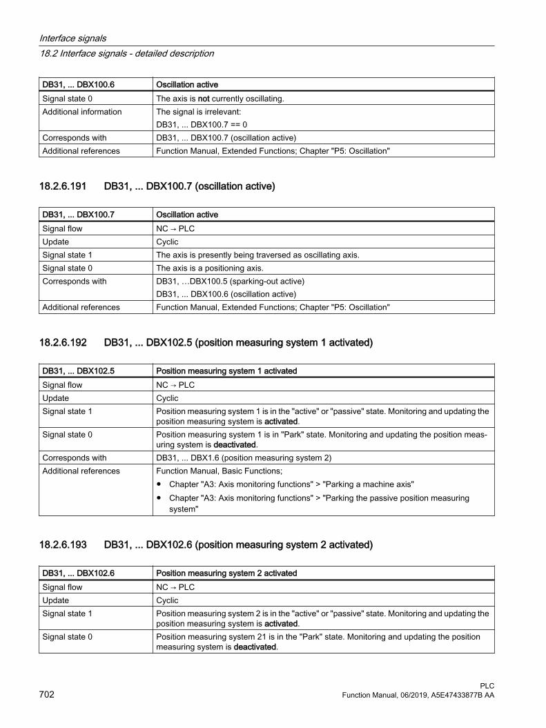
DB31, ... DBX100.6 Oscillation activeSignal state 0 The axis is not currently oscillating.Additional information The signal is irrelevant:
DB31, ... DBX100.7 == 0Corresponds with DB31, ... DBX100.7 (oscillation active)Additional references Function Manual, Extended Functions; Chapter "P5: Oscillation"
18.2.6.191 DB31, ... DBX100.7 (oscillation active)
DB31, ... DBX100.7 Oscillation activeSignal flow NC → PLCUpdate CyclicSignal state 1 The axis is presently being traversed as oscillating axis.Signal state 0 The axis is a positioning axis.Corresponds with DB31, …DBX100.5 (sparking-out active)
DB31, ... DBX100.6 (oscillation active)Additional references Function Manual, Extended Functions; Chapter "P5: Oscillation"
18.2.6.192 DB31, ... DBX102.5 (position measuring system 1 activated)
DB31, ... DBX102.5 Position measuring system 1 activatedSignal flow NC → PLCUpdate CyclicSignal state 1 Position measuring system 1 is in the "active" or "passive" state. Monitoring and updating the
position measuring system is activated.Signal state 0 Position measuring system 1 is in "Park" state. Monitoring and updating the position meas‐
uring system is deactivated.Corresponds with DB31, ... DBX1.6 (position measuring system 2)Additional references Function Manual, Basic Functions;
● Chapter "A3: Axis monitoring functions" > "Parking a machine axis" ● Chapter "A3: Axis monitoring functions" > "Parking the passive position measuring
system"
18.2.6.193 DB31, ... DBX102.6 (position measuring system 2 activated)
DB31, ... DBX102.6 Position measuring system 2 activatedSignal flow NC → PLCUpdate CyclicSignal state 1 Position measuring system 2 is in the "active" or "passive" state. Monitoring and updating the
position measuring system is activated.Signal state 0 Position measuring system 21 is in the "Park" state. Monitoring and updating the position
measuring system is deactivated.
Interface signals18.2 Interface signals - detailed description
PLC702 Function Manual, 06/2019, A5E47433877B AA

DB31, ... DBX102.6 Position measuring system 2 activatedCorresponds with DB31, ... DBX1.5 (position measuring system 1)Additional references Function Manual, Basic Functions;
● Chapter "A3: Axis monitoring functions" > "Parking a machine axis" ● Chapter "A3: Axis monitoring functions" > "Parking the passive position measuring
system"
18.2.6.194 DB31, ... DBX104.0 - 107.6 (active infeed axes)
DB31, ... DBX104.0 - 107.6: Active infeed axesSignal flow NC → PLCUpdate CyclicSignal state 1 For the actual axis (oscillating axis), the corresponding axis is an infeed axis.Signal state 0 For the actual axis (oscillating axis), the corresponding axis is not an infeed axis.Additional information DBB Bit 7 Bit 6 ... Bit 1 Bit 0
104 Axis 8 Axis 7 ... Axis 2 Axis 1105 Axis 16 Axis 15 ... Axis 10 Axis 9106 Axis 24 Axis 23 ... Axis 18 Axis 17107 --- Axis 31 ... Axis 26 Axis 25
Corresponds with DB31, ... DBX100.7 (oscillation active)Additional references Function Manual, Extended Functions; Chapter "P5: Oscillation"
18.2.6.195 DB31, ... DBX128.0 (suppress program test)
DB31, ... DBX128.0 Suppress program testSignal flow HMI → PLCUpdate CyclicSignal state 1 Suppression of the program test (setpoint output locked) is requested by the HMI.Signal state 0 Suppression of the program test (setpoint output locked) is not requested by the HMI.Additional information If function "Program test" (PRT) is active in the channel to which the axis currently belongs,
the axis is traversed with internal axis disable. Setpoints are generated but they not output to the machine axes. Actual value = Setpoint. If the program test is suppressed for the axis, setpoints are output to the machine axis despite the function "program test" being active in the channel to which the axis currently belongs.Automatic transfer of the interface signalsThe HMI request signals DB21, ... DBX128.0 / .1 are only transferred from the basic PLC program to the PLC request signals DB21, ... DBX14.0 / .1 if FB1 parameter MMCToIF is set to TRUE. If the parameter is not set, the PLC request signals must be set by the PLC user program.
Corresponds with DB31, ... DBX14.0 (suppress program test)DB31, ... DBX14.1 (activate program test)DB31, ... DBX128.1 (activate program test)
Additional references Function Manual Extended Functions, Chapter "K5: Cross-channel program coordination" > "Channel-by-channel running-in"
Interface signals18.2 Interface signals - detailed description
PLCFunction Manual, 06/2019, A5E47433877B AA 703

18.2.6.196 DB31, ... DBX128.1 (activate program test)
DB31, ... DBX128.1 Activate program testSignal flow HMI → PLCUpdate CyclicSignal state 1 Activation of the function "program test" (setpoint output locked) is requested by the HMI.Signal state 0 Activation of the function "program test" (setpoint output locked) is not requested by the HMI.Additional information If the function "program test" is active, the axis is traversed with internal axis disable. Setpoints
are generated but they not output to the machine axes. Actual value = Setpoint. Automatic transfer of the interface signalsThe HMI request signals DB21, ... DBX128.0 / .1 are only transferred from the basic PLC program to the PLC request signals DB21, ... DBX14.0 / .1 if FB1 parameter MMCToIF is set to TRUE. If the parameter is not set, the PLC request signals must be set by the PLC user program.
Corresponds with DB31, ... DBX14.0 (suppress program test)DB31, ... DBX14.1 (activate program test)DB31, ... DBX128.0 (suppress program test)
Additional references Function Manual Extended Functions, Chapter "K5: Cross-channel program coordination" > "Channel-by-channel running-in"
18.2.6.197 DB31, ... DBX130.0 - 4 (motor/drive data set: formatting)
DB31, ... DBX130.0 - 4 Motor/drive data set: FormattingSignal flow NC → PLCUpdate CyclicAdditional information Formatting interface for the currently active motor (MDS) / drive data set (DDS).Corresponds with DB31, ... DBX21.0 - 4 (motor/drive data set: selection)
DB31, ... DBX21.5 (motor has been selected)DB31, ... DBX93.0 - 4 (motor/drive data set: display)
Additional references ● Function Manual, Basic Functions, Chapter "A2: Various NC/PLC interface signals and functions" > "Switchover motor/drive data sets"
● SINUMERIK 840D sl Commissioning Manual, CNC Commissioning: NC, PLC, Drive
18.2.6.198 DB31, ... DBX132.0 (sensors available)
DB31, ... DBX132.0 Sensors availableSignal flow NC → PLCUpdate CyclicSignal state 1 The sensor required for spindles with SMI 24 is available.Signal state 0 The sensor required for spindles with SMI 24 is not available.Additional information Note
Only relevant for spindles with SMI 24 (Weiss spindle)
Interface signals18.2 Interface signals - detailed description
PLC704 Function Manual, 06/2019, A5E47433877B AA

DB31, ... DBX132.0 Sensors availableCorresponds with DB31, … DBX132.1: Sensor S1 (clamped state) is available
DB31, … DBX132.4: Sensor S4 is availableDB31, … DBX132.5: Sensor S5 is available
Additional references Basic Functions Function Manual; Chapter "S1: spindles"
18.2.6.199 DB31, ... DBX132.1 (sensor S1 available (clamped state))
DB31, ... DBX132.1 Sensor S1 available (clamped state)Signal flow NC → PLCUpdate CyclicSignal state 1 Sensor S1 is available.Signal state 0 Sensor S1 is not available.Additional information Note
Only relevant for spindles with SMI 24 (Weiss spindle)Corresponds with DB31, … DBW134 (state of the clamping system)
DB31, … DBW136 (analog value: clamped state)Additional references Basic Functions Function Manual; Chapter "S1: spindles"
18.2.6.200 DB31, … DBX132.4 (sensor S4 available (piston end position))
DB31, ... DBX132.4 Sensor S4 available (piston end position)Signal flow NC → PLCUpdate CyclicSignal state 1 Sensor S4 is available.Signal state 0 Sensor S4 is not available.Additional information Note
Only relevant for spindles with SMI 24 (Weiss spindle)Corresponds with DB31, … DBX138.4 (sensor S4: piston end position)Additional references Basic Functions Function Manual; Chapter "S1: spindles"
18.2.6.201 DB31, ... DBX132.5 (sensor S5 available (angular position of the motor shaft))
DB31, ... DBX132.5 Sensor S5 available (angular position of the motor shaft)Signal flow NC → PLCUpdate CyclicSignal state 1 Sensor S5 is available.Signal state 0 Sensor S5 is not available.Additional information Note
Only relevant for spindles with SMI 24 (Weiss spindle)
Interface signals18.2 Interface signals - detailed description
PLCFunction Manual, 06/2019, A5E47433877B AA 705

DB31, ... DBX132.5 Sensor S5 available (angular position of the motor shaft)Corresponds with DB31, … DBX138.5 (sensor S5: angular position of the motor shaft)Additional references Basic Functions Function Manual; Chapter "S1: spindles"
18.2.6.202 DB31, ... DBX133.2 (state value is generated, speed limitation p5043 is active)
DB31, ... DBX133.2 State value is generated, speed limitation p5043 is active Signal flow NC → PLCUpdate CyclicSignal state 1 The status value is generated and the speed limits from drive parameter p5043 are active.Signal state 0 The status value is not generated and the speed limits from drive parameter p5043 are not
active.Additional information Note
● Only relevant for spindles with SMI 24 (Weiss spindle)● When generating the status value, the analog voltage values of sensor S1 are transformed
into discrete status values of drive parameter r5001.Corresponds with DB31, … DBX134 (clamped state)
Drive parameters: r5001System variable: $VA_MOT_CLAMPING_STATE[<axis>]OPI variable: vaMotClampingState
Additional references Basic Functions Function Manual; Chapter "S1: spindles"
18.2.6.203 DB31, … DBW134 (state of the clamping system (sensor S1))
DB31, ... DBW134 State of the clamping system (sensor S1)Signal flow NC → PLCUpdate Cyclic
Interface signals18.2 Interface signals - detailed description
PLC706 Function Manual, 06/2019, A5E47433877B AA

DB31, ... DBW134 State of the clamping system (sensor S1)Additional information Note
Only relevant for spindles with SMI 24 (Weiss spindle)Depending on the position of the clamping device, sensor S1 supplies an analog voltage value. To simplify the evaluation of the clamped state, the analog voltage of sensor module SMI 24 is converted into a state value. The state values correspond to certain voltage ranges. The voltage ranges can be set via: Drive parameter p5041[0...5].
State value Clamped state0 Sensor S1 not available or state values inactive1 State initialization running2 Released with signal (error state)3 Released4 Clamping with tool5 Releasing with tool6 Releasing without tool7 Clamped with tool AND S4 == 08 Clamped with tool AND S4 == 19 Clamping without tool10 Clamped without tool11 Clamped with signal (error state)
Corresponds with DB31, … DBW136 (analog value: clamped state)Drive parameters: p5041[0...5], p5043[0...6]
Additional references Basic Functions Function Manual; Chapter "S1: spindles"
18.2.6.204 DB31, ... DBW136 (analog measured value: of the clamping system)
DB31, ... DBW136 Analog measured value: of the clamping systemSignal flow NC → PLCUpdate CyclicAdditional information Note
Only relevant for spindles with SMI 24 (Weiss spindle)Sensor S1 supplies an analog voltage value: 0 - 10 V. The analog value of the clamped state is mapped to: 0 - 10000 increments, resolution 1 mVNoteSIMATIC S7 input module: 0 - 27648 increments, resolution 0.36 mVAdaptation factor if you change to a spindle with SMI 24: 2.7648
Corresponds with DB31, … DBW134 (clamped state)Drive parameters: p5041[0...5], p5043[0...6]
Additional references Basic Functions Function Manual; Chapter "S1: spindles"
Interface signals18.2 Interface signals - detailed description
PLCFunction Manual, 06/2019, A5E47433877B AA 707

18.2.6.205 DB31, … DBX138.4 (sensor S4, piston end position)
DB31, ... DBX138.4 Sensor S4, piston end positionSignal flow NC → PLCUpdate CyclicSignal state 1 The piston is in position, i.e. the piston is free to moveSignal state 0 The piston is not in positionAdditional information Note
Only relevant for spindles with SMI 24 (Weiss spindle)Corresponds with DB31, … DBX132.4 (sensor S4 available)Additional references Basic Functions Function Manual; Chapter "S1: spindles"
18.2.6.206 DB31, ... DBX138.5 (sensor S5 angular position of the motor shaft)
DB31, ... DBX138.5 Sensor S5, angular position of the motor shaftSignal flow NC → PLCUpdate CyclicSignal state 1 The motor shaft is in position (requirement: the spindle is stationary)Signal state 0 The motor shaft is not alignedAdditional information Note
Only relevant for spindles with SMI 24 (Weiss spindle)Corresponds with DB31, … DBX132.5 (sensor S5 available)Additional references Basic Functions Function Manual; Chapter "S1: spindles"
18.2.7 DB71. Tool management, loading/unloading points
18.2.7.1 DB71 DBX0.0 - 1.7 (active status of interfaces 1 - 16)
DB71 DBX0.0 - 1.7 Active status of interfaces 1- 16Signal flow NC → PLCUpdate Job-controlledSignal state 1 The interface is active.Signal state 0 The interface is not active. Additional information If an interface is active, then a valid data set exists for this interface.
Assignment of the interfaces: Bit 7 Bit 6 Bit 5 Bit 4 Bit 3 Bit 2 Bit 1 Bit 0
DBB0 INT 8 INT 7 INT 6 INT 5 INT 4 INT 3 INT 2 INT 1DBB1 INT 16 INT 15 INT 14 INT 13 INT 12 INT 11 INT 10 INT 9
Interface signals18.2 Interface signals - detailed description
PLC708 Function Manual, 06/2019, A5E47433877B AA

18.2.7.2 DB71 DBX2.0 - 3.7 ("auto" acknowledgment of interfaces 1 - 16)
DB71 DBX2.0 - 3.7 "auto" acknowledgment of interfaces 1 - 16 Signal flow NC → PLCUpdate Job-controlledSignal state 0 → 1 When setting (edge) the bit, the active command is acknowledged with status_1. Unless it is
a relocation operation from a real magazine to a buffer. Then acknowledgment is made with status_6. This reserves the source location. e. g. U DB71 DBX0.0 U DB71 DBX4.1 (unload) S DB71 DBX2.0
Signal state 1 → 0 Operation for this interface has ended. Is reset by the basic program.
18.2.7.3 DB71 DBX(n+0).0 (command: Loading)
DB71 DBX(n+0).0 Command: LoadingSignal flow NC → PLCUpdate Job-controlledSignal state 1 Loading operation for a tool is initiated. The magazine location into which the tool is to be
loaded is defined in DBW(n+26). The loading point in question is the location number of the loading point. It is also located in DBW(n+18)
Additional information The bits in DBB(n+0) (loading, unloading,....) are not updated by the basic program until a new task exists for this interface. They are only current (up-to-date) if the corresponding interface bit in DBB0 is set to "1''. If required, the user can reset bits DBB(n+0).
Additional information Start addressesThe start addresses n of the loading/unloading points are 1 - 4:● Loading/unloading point 1: n = 4 ● Loading/unloading point 2: n = 34 ● Loading/unloading point 3: n = 64 ● Loading/unloading point 4: n = 94
Corresponds with DB71 DBX(n+16) and (n+18) and (n+26)
18.2.7.4 DB71 DBX(n+0).1 (command: Unload)
DB71 DBX(n+0).1 Command: UnloadSignal flow NC → PLCUpdate Job-controlledSignal state 1 Unloading operation is initiated for a tool; the magazine location from which it is to be unloaded
is in DBW (n+20) and DBW (n+22). The number of the unloading point is in DBW(n+18).Edge evaluation Signal(s) updated: ConditionalAdditional information The bits in DBB(n+0) (loading, unloading,....) are not updated by the basic program until a new
task exists for this interface. They are only current (up-to-date) if the corresponding interface bit in DBB0 is set to "1''. If required, the user can reset bits DBB(n+0).
Interface signals18.2 Interface signals - detailed description
PLCFunction Manual, 06/2019, A5E47433877B AA 709

DB71 DBX(n+0).1 Command: UnloadAdditional information Starting addresses of loading/unloading points:
Loading/unloading point 1: n = 4 Loading/unloading point 2: n = 34 Loading/unloading point 3: n = 64 Loading/unloading point 4: n = 94
Corresponds with DB71 DBX(n+16) and (n+18) or (n+20) and (n+22)
18.2.7.5 DB71 DBX(n+0).2 (command: Relocate)
DB71 DBX(n+0).2 Command: RelocateSignal flow NC → PLCUpdate Job-controlledSignal state 1 Relocation operation for a tool is initiated. From magazine/location (n+20, n+22=source) to
magazine/location (n+24, n+26=target)Signal state 0 Relocation operation for a tool is not initiated.Additional information Starting addresses of loading/unloading points:
Loading/unloading point 1: n = 4 Loading/unloading point 2: n = 34 Loading/unloading point 3: n = 64 Loading/unloading point 4: n = 94The bits in DBB(n+0) (loading, unloading,....) are not updated by the basic program until a new task exists for this interface. They are only current (up-to-date) if the corresponding interface bit in DBB0 is set to "1''. If required, the user can reset bits DBB(n+0).
18.2.7.6 DB71 DBX(n+0).3 (command: Position to load point)
DB71 DBX(n+0).3 Command: Position to the loading pointSignal flow NC → PLCUpdate Job-controlledSignal state 1 A magazine location is to be positioned at the loading point (magazine No. 9999). The mag‐
azine location that is to be moved to the loading point is in DB71.DBW(n+20) and (n+22). The loading location is in DB71.DBWn+18.
Signal state 0 A magazine location is not to be positioned at the loading point (magazine No. 9999). Additional information Starting addresses of loading/unloading points:
Loading/unloading point 1: n = 4 Loading/unloading point 2: n = 34 Loading/unloading point 3: n = 64 Loading/unloading point 4: n = 94The bits in DBB(n+0) (loading, unloading,....) are not updated by the basic program until a new task exists for this interface. They are only current (up-to-date) if the corresponding interface bit in DBB0 is set to "1''. If required, the user can reset bits DBB(n+0).
Interface signals18.2 Interface signals - detailed description
PLC710 Function Manual, 06/2019, A5E47433877B AA

18.2.7.7 DB71 DBX(n+0).4 (command: Job/task comes from the NC program)
DB71 DBX(n+0).4 Command: Task comes from the NC programSignal flow NC → PLCUpdate Job-controlledSignal state 1 The signal is set if the task is received from the part program or via a cycle.
1. Positioning task with the language command POSM2. A relocation task or tool transport uses the language command MVTOOL3. Positioning a multitool using the language command POSMT
Signal state 0 The signal is not set.Additional information Starting addresses of loading/unloading points:
Loading/unloading point 1: n = 4 Loading/unloading point 2: n = 34 Loading/unloading point 3: n = 64 Loading/unloading point 4: n = 94The bits in DBB(n+0) (loading, unloading,....) are not updated by the basic program until a new task exists for this interface. They are only current (up-to-date) if the corresponding interface bit in DBB0 is set to "1''. If required, the user can reset bits DBB(n+0).
18.2.7.8 DB71 DBX(n+0).5 (command: Position a multitool)
DB71 DBX(n+0).5 Command: Position a multitoolSignal flow NC → PLCUpdate Job-controlledSignal state 1 Positioning a multitool has been initiated. This can be realized using a language command, PI
service or the HMI user interface.Signal state 0 The signal is not set.Additional information Starting addresses of loading/unloading points:
Loading/unloading point 1: n = 4 Loading/unloading point 2: n = 34 Loading/unloading point 3: n = 64 Loading/unloading point 4: n = 94The bits in DBB(n+0) (loading, unloading,....) are not updated by the basic program until a new task exists for this interface. They are only current (up-to-date) if the corresponding interface bit in DBB0 is set to "1''. If required, the user can reset bits DBB(n+0).
18.2.7.9 DB71 DBX(n+1).0 ("auto" acknowledgment negative)
DB71 DBX(n+1).0 "auto" acknowledgment negativeSignal flow NC → PLCUpdate Job-controlledSignal state 1 The bit is only evaluated in conjunction with "auto" ackn. If it is set, then the auto acknowledge
is negative, i.e. with status_3.
Interface signals18.2 Interface signals - detailed description
PLCFunction Manual, 06/2019, A5E47433877B AA 711

DB71 DBX(n+1).0 "auto" acknowledgment negativeSignal state 0 The bit is not set.Additional information Starting addresses of loading/unloading points:
Loading/unloading point 1: n = 4 Loading/unloading point 2: n = 34 Loading/unloading point 3: n = 64 Loading/unloading point 4: n = 94
18.2.7.10 DB71 DBX(n+1).7 (command: data in the extended range)
DB71 DBX(n+1).7 Command: Data in the extended rangeSignal flow NC → PLCUpdate Job-controlledSignal state 1 The signal is set if a multitool is loaded, unloaded or positioned. The multitool data are then
available in DB1071.Signal state 0 The signal is not set.Additional information Starting addresses of loading/unloading points:
Loading/unloading point 1: n = 4 Loading/unloading point 2: n = 34 Loading/unloading point 3: n = 64 Loading/unloading point 4: n = 94
18.2.7.11 DB71 DBB(n+2) (assigned channel)
DB71 DBB(n+2) Assigned channelSignal flow NC → PLCUpdate Job-controlledSignal state 1 Number of the channel for which the active interface is valid.Signal state 0 No channel numberAdditional information Starting addresses of loading/unloading points:
Loading/unloading point 1: n = 4 Loading/unloading point 2: n = 34 Loading/unloading point 3: n = 64 Loading/unloading point 4: n = 94
18.2.7.12 DB71 DBB(n+3) (tool management No.)
DB71 DBB(n+3) Tool management No.Signal flow NC → PLCUpdate Job-controlledSignal state 1 Associated tool management number; corresponds to the number of the TO unit within a TO
area.
Interface signals18.2 Interface signals - detailed description
PLC712 Function Manual, 06/2019, A5E47433877B AA
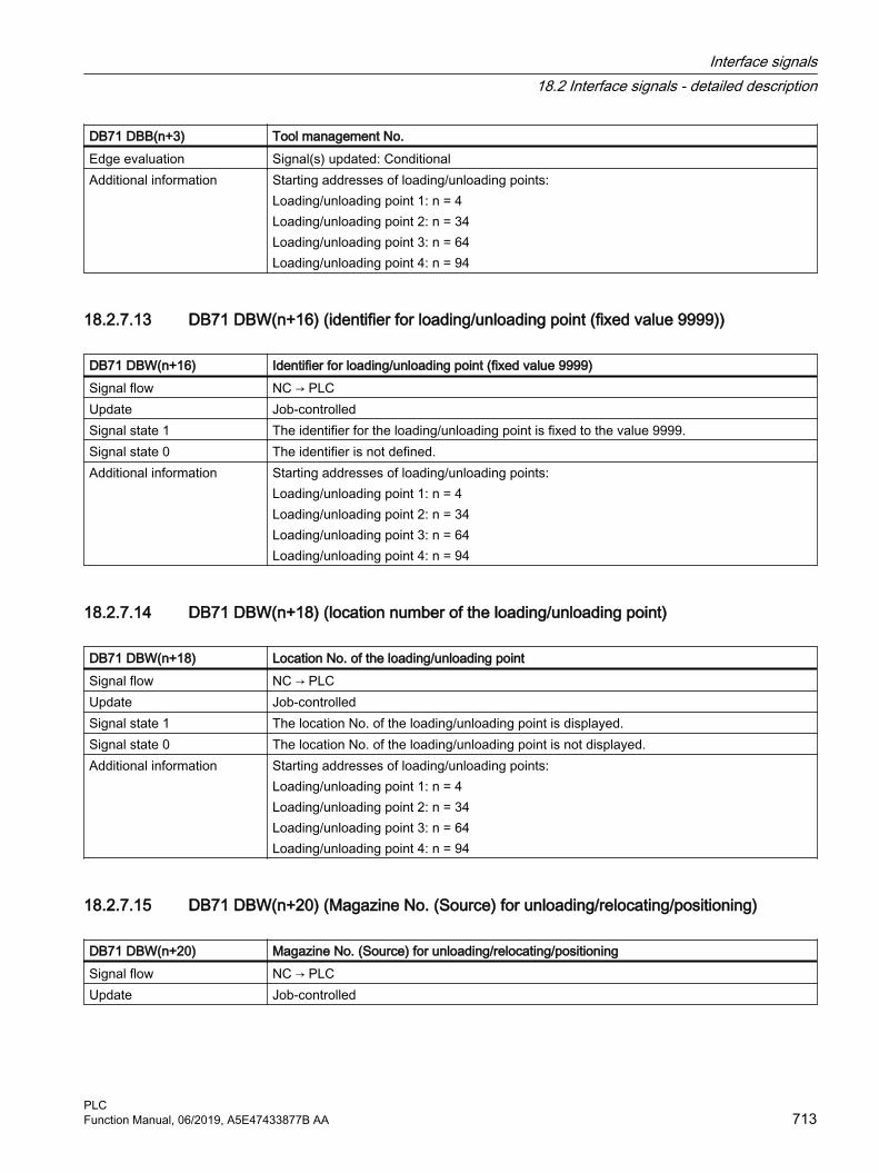
DB71 DBB(n+3) Tool management No.Edge evaluation Signal(s) updated: ConditionalAdditional information Starting addresses of loading/unloading points:
Loading/unloading point 1: n = 4 Loading/unloading point 2: n = 34 Loading/unloading point 3: n = 64 Loading/unloading point 4: n = 94
18.2.7.13 DB71 DBW(n+16) (identifier for loading/unloading point (fixed value 9999))
DB71 DBW(n+16) Identifier for loading/unloading point (fixed value 9999)Signal flow NC → PLCUpdate Job-controlledSignal state 1 The identifier for the loading/unloading point is fixed to the value 9999.Signal state 0 The identifier is not defined.Additional information Starting addresses of loading/unloading points:
Loading/unloading point 1: n = 4 Loading/unloading point 2: n = 34 Loading/unloading point 3: n = 64 Loading/unloading point 4: n = 94
18.2.7.14 DB71 DBW(n+18) (location number of the loading/unloading point)
DB71 DBW(n+18) Location No. of the loading/unloading pointSignal flow NC → PLCUpdate Job-controlledSignal state 1 The location No. of the loading/unloading point is displayed.Signal state 0 The location No. of the loading/unloading point is not displayed.Additional information Starting addresses of loading/unloading points:
Loading/unloading point 1: n = 4 Loading/unloading point 2: n = 34 Loading/unloading point 3: n = 64 Loading/unloading point 4: n = 94
18.2.7.15 DB71 DBW(n+20) (Magazine No. (Source) for unloading/relocating/positioning)
DB71 DBW(n+20) Magazine No. (Source) for unloading/relocating/positioningSignal flow NC → PLCUpdate Job-controlled
Interface signals18.2 Interface signals - detailed description
PLCFunction Manual, 06/2019, A5E47433877B AA 713

DB71 DBW(n+20) Magazine No. (Source) for unloading/relocating/positioningSignal state 1 Unloading: Magazine from which the tool is to be unloaded
Relocating: Magazine from which the tool is received Positioning: Magazine that is to be positioned
Signal state 0 No magazine is unloaded, relocated or positioned.Additional information Starting addresses of loading/unloading points:
Loading/unloading point 1: n = 4 Loading/unloading point 2: n = 34 Loading/unloading point 3: n = 64 Loading/unloading point 4: n = 94
Corresponds with DBW(n+22)
18.2.7.16 DB71 DBW(n+22) (Location No. (Source) for unloading/relocating/positioning)
DB71 DBW(n+22) Location No. (Source) for unloading/relocating/positioningSignal flow NC → PLCUpdate Job-controlledSignal state 1 Unloading: Location from which the tool is to be unloaded
Relocating: Location from where the tool is received Positioning: Location that should be positioned
Signal state 0 No tool is unloaded, relocated, positioned from any location.Additional information Starting addresses of loading/unloading points:
Loading/unloading point 1: n = 4 Loading/unloading point 2: n = 34 Loading/unloading point 3: n = 64 Loading/unloading point 4: n = 94
Corresponds with DBW(n+20)
18.2.7.17 DB71 DBW(n+24) (Magazine No. (Target) for unloading/relocating/positioning)
DB71 DBW(n+24) Magazine No. (Target) for unloading/relocating/positioningSignal flow NC → PLCUpdate Job-controlledSignal state 1 Loading: Magazine into which the tool is to be loaded
Relocating: Magazine into which the tool is loaded: Positioning: Magazine to be positioned to - tool remains in the original magazine Only meaningful for interface 1. If values other than 0 are entered here, the data define the magazine or location for positioning (language command POSM).
Signal state 0 No magazine number specified.
Interface signals18.2 Interface signals - detailed description
PLC714 Function Manual, 06/2019, A5E47433877B AA

DB71 DBW(n+24) Magazine No. (Target) for unloading/relocating/positioningAdditional information Starting addresses of loading/unloading points:
Loading/unloading point 1: n = 4 Loading/unloading point 2: n = 34 Loading/unloading point 3: n = 64 Loading/unloading point 4: n = 94
Corresponds with DBW(n+26)
18.2.7.18 DB71 DBW(n+26) (location No. (Target) for unloading/relocating/positioning)
DB71 DBW(n+26) Location No. (Target) for unloading/relocating/positioningSignal flow NC → PLCUpdate Job-controlledSignal state 1 Loading: Location into which the tool is to be loaded
Relocating: Location into which the tool comes Positioning: Location at which the tool must be positioned. Tool remains at original location Only meaningful for interface 1. If values other than 0 are entered here, the data define the magazine or location for positioning (language command POSM).
Signal state 0 No location number specified for loading, relocating, positioning.Additional information Starting addresses of loading/unloading points:
Loading/unloading point 1: n = 4 Loading/unloading point 2: n = 34 Loading/unloading point 3: n = 64 Loading/unloading point 4: n = 94
Corresponds with DBW(n+24)
18.2.7.19 DB71 DBX(n+28).0 (loading/unloading without any magazine movement)
DB71 DBX(n+28).0 Loading/unloading without magazine movementSignal flow NC → PLCUpdate Job-controlledSignal state 1 HMI / Jobshop sets this signal when requested by the operator.
If the bit is active, there must be no traversing motion of the magazine, only a mechanical unlocking/locking of the location. The load/unload command must be acknowledged after the action. For a positioning and relocating request, this signal is not valid for a traversing motion.
Signal state 0 HMI / Jobshop delete this signal when requested by the operator. Additional information Starting addresses of loading/unloading points:
Loading/unloading point 1: n = 4 Loading/unloading point 2: n = 34 Loading/unloading point 3: n = 64 Loading/unloading point 4: n = 94
Interface signals18.2 Interface signals - detailed description
PLCFunction Manual, 06/2019, A5E47433877B AA 715

18.2.8 DB72: Tool management, change in the spindle
18.2.8.1 DB72 DBX0.0-1.7 (active status of interfaces 1-16)
DB72 DBX0.0-1.7 Active status of interfaces 1-16Signal flow NC → PLCUpdate Job-controlledSignal state 1 Associated interface has a valid data set, a tool change request or tool preparation has been
initiated.Signal state 0 Operation for this interface has ended. Is reset by FC8/FC6.Additional information Start address of the spindle:
Spindle 1: n = 4 Spindle 2: n = 52 Spindle 3: n = 100
18.2.8.2 DB72 DBX2.0-3.7 ("auto" acknowledgment of interfaces 1-16)
DB72 DBX2.0-3.7 "auto" acknowledgment of interfaces 1-16Signal flow NC → PLCUpdate Job-controlledSignal state 1 When setting (edge) the bit, the active command is acknowledged with status_1.Signal state 0 Operation for this interface has ended. Is reset by the basic program.Additional information Start address of the spindle:
Spindle 1: n = 4 Spindle 2: n = 52 Spindle 3: n = 100
18.2.8.3 DB72 DBX(n+0).0 (command code: Obligatory change)
DB72 DBX(n+0).0 Command code: Obligatory changeSignal flow NC → PLCUpdate Job-controlledSignal state 1 The new tool is fixed-location-coded.
Interface signals18.2 Interface signals - detailed description
PLC716 Function Manual, 06/2019, A5E47433877B AA

DB72 DBX(n+0).0 Command code: Obligatory changeSignal state 1 The new tool is fixed-location-coded.Additional information Start address of the spindle:
Spindle 1: n = 4 Spindle 2: n = 52 Spindle 3: n = 100The bit in DBB (n+0).2 (prepare change) is not reset by the system with a change command. The bits in DBB(n+0) ... are current only if the corresponding interface bit in DBB0 is set to "1''. However, the bits can be reset by the user if necessary. If DBX(n+0).1 and DBX(n+0).2 are present at the same time, it means that T and M06 were programmed in one block.
18.2.8.4 DB72 DBX(n+0).1 (command code: Perform change with M06)
DB72 DBX(n+0).1 Command code: Perform change with M06Signal flow NC → PLCUpdate Job-controlledSignal state 1 M06 command was programmed for tool change, the tool change can now take placeSignal state 0 M06 command for tool change was not programmed.Additional information Start address of the spindle:
Spindle 1: n = 4 Spindle 2: n = 52 Spindle 3: n = 100The bit in DBB(n+0).2 (prepare change) is not reset by the system with a change command. The bits in DBB(n+0) are up to date only if the corresponding interface bit in DBB0 is set to "1''. However, the bits can be reset by the user if necessary. If DBX(n+0).1 and DBX(n+0).2 are present at the same time, it means that T and M06 were programmed in one block.
18.2.8.5 DB72 DBX(n+0).2 (command code: Prepare change)
DB72 DBX(n+0).2 Command code: Prepare changeSignal flow NC → PLCUpdate Job-controlledSignal state 1 Prepare new tool for change. If necessary, move location for old tool to spindle.
Interface signals18.2 Interface signals - detailed description
PLCFunction Manual, 06/2019, A5E47433877B AA 717
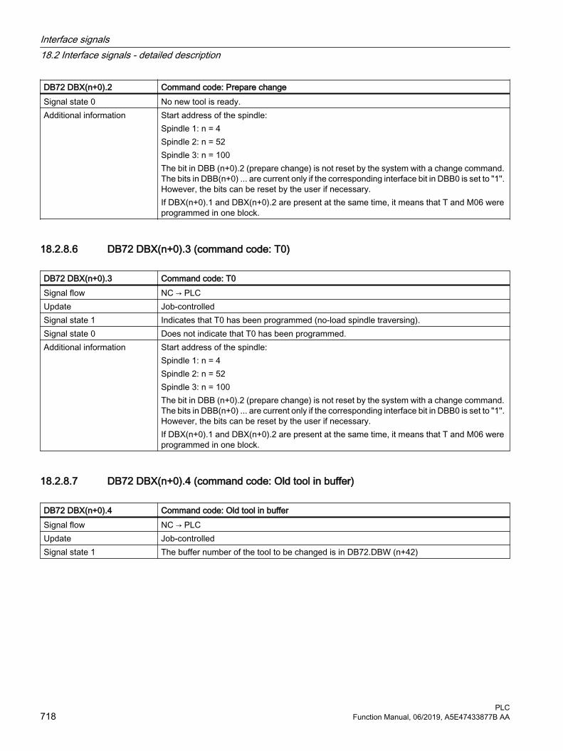
DB72 DBX(n+0).2 Command code: Prepare changeSignal state 0 No new tool is ready.Additional information Start address of the spindle:
Spindle 1: n = 4 Spindle 2: n = 52 Spindle 3: n = 100The bit in DBB (n+0).2 (prepare change) is not reset by the system with a change command. The bits in DBB(n+0) ... are current only if the corresponding interface bit in DBB0 is set to "1''. However, the bits can be reset by the user if necessary. If DBX(n+0).1 and DBX(n+0).2 are present at the same time, it means that T and M06 were programmed in one block.
18.2.8.6 DB72 DBX(n+0).3 (command code: T0)
DB72 DBX(n+0).3 Command code: T0Signal flow NC → PLCUpdate Job-controlledSignal state 1 Indicates that T0 has been programmed (no-load spindle traversing).Signal state 0 Does not indicate that T0 has been programmed.Additional information Start address of the spindle:
Spindle 1: n = 4 Spindle 2: n = 52 Spindle 3: n = 100The bit in DBB (n+0).2 (prepare change) is not reset by the system with a change command. The bits in DBB(n+0) ... are current only if the corresponding interface bit in DBB0 is set to "1''. However, the bits can be reset by the user if necessary. If DBX(n+0).1 and DBX(n+0).2 are present at the same time, it means that T and M06 were programmed in one block.
18.2.8.7 DB72 DBX(n+0).4 (command code: Old tool in buffer)
DB72 DBX(n+0).4 Command code: Old tool in bufferSignal flow NC → PLCUpdate Job-controlledSignal state 1 The buffer number of the tool to be changed is in DB72.DBW (n+42)
Interface signals18.2 Interface signals - detailed description
PLC718 Function Manual, 06/2019, A5E47433877B AA

DB72 DBX(n+0).4 Command code: Old tool in bufferSignal state 0 The buffer number of the tool to be changed is not in DB72.DBW (n+42)Additional information Start address of the spindle:
Spindle 1: n = 4Spindle 2: n = 52Spindle 3: n = 100The bit in DBB(n+0).2 (prepare change) is not reset by the system with a change command. The bits in DBB(n+0) ... are current only if the corresponding interface bit in DBB0 is set to "1''. However, the bits can be reset by the user if necessary. If DBX(n+0).1 and DBX(n+0).2 are present at the same time, it means that T and M06 were programmed in one block.
18.2.8.8 DB72 DBX(n+0).5 (command code: Load manual tool)
DB72 DBX(n+0).5 Command code: Load manual toolSignal flow NC → PLCUpdate Job-controlledSignal state 1 A manual tool is to be loaded. The HMI displays the tool which is to be loaded.Signal state 0 No new manual tool is loaded.Edge evaluation Signal(s) updated: ConditionalAdditional information Start address of the spindle:
Spindle 1: n = 4 Spindle 2: n = 52 Spindle 3: n = 100The bit in DBB(n+0).2 (prepare change) is not reset by the system with a change command. The bits in DBB(n+0) ... are current only if the corresponding interface bit in DBB0 is set to "1''. However, the bits can be reset by the user if necessary. If DBX(n+0).1 and DBX(n+0).2 are present at the same time, it means that T and M06 were programmed in one block.
18.2.8.9 DB72 DBX(n+0).6 (command code: Unload manual tool)
DB72 DBX(n+0).6: Command code: Unload manual toolSignal flow NC → PLCUpdate Job-controlledSignal state 1 The tool is to be changed via manual operation.Signal state 0 The tool is not to be changed via manual operation.
Interface signals18.2 Interface signals - detailed description
PLCFunction Manual, 06/2019, A5E47433877B AA 719

DB72 DBX(n+0).6: Command code: Unload manual toolEdge evaluation Signal(s) updated: ConditionalAdditional information Start address of the spindle:
Spindle 1: n = 4 Spindle 2: n = 52 Spindle 3: n = 100The bit in DBB(n+0).2 (prepare change) is not reset by the system with a change command. The bits in DBB(n+0) ... are current only if the corresponding interface bit in DBB0 is set to "1''. However, the bits can be reset by the user if necessary. If DBX(n+0).1 and DBX(n+0).2 are present at the same time, it means that T and M06 were programmed in one block.
18.2.8.10 DB72 DBX(n+0).7 (command code: Tool remains in spindle)
DB72 DBX(n+0).7 Command code: Tool remains in spindleSignal flow NC → PLCUpdate Job-controlledSignal state 1 The bit is set at change from spindle to spindle. Initiated, e.g. by reset and start mode or block
search.Signal state 0 The bit is not set at change from spindle to spindle.Edge evaluation Signal(s) updated: ConditionalAdditional information Start address of the spindle:
Spindle 1: n = 4 Spindle 2: n = 52 Spindle 3: n = 100The bit in DBB(n+0).2 (prepare change) is not reset by the system with a change command. The bits in DBB(n+0) ... are current only if the corresponding interface bit in DBB0 is set to "1''. However, the bits can be reset by the user if necessary. If DBX(n+0).1 and DBX(n+0).2 are present at the same time, it means that T and M06 were programmed in one block.
18.2.8.11 DB72 DBX(n+1).0 ("auto" acknowledgment negative)
DB72 DBX(n+1).0 "auto" acknowledgment negativeSignal flow NC → PLCUpdate Job-controlledSignal state 1 The bit is only evaluated in conjunction with "auto" ackn. If it is set, the auto acknowledge is
negative, i.e. with status_3.Signal state 0 Bit is not evaluated.Edge evaluation Signal(s) updated: ConditionalAdditional information Start address of the spindle:
Spindle 1: n = 4 Spindle 2: n = 52 Spindle 3: n = 100
Interface signals18.2 Interface signals - detailed description
PLC720 Function Manual, 06/2019, A5E47433877B AA

18.2.8.12 DB72 DBX(n+1).7 (command: data in the extended range)
DB72 DBX(n+1).7 Command: Data in the extended rangeSignal flow NC → PLCUpdate Job-controlledSignal state 1 The signal is set if a tool is prepared in a multitool or is loaded into a multitool. DB72 contains
the data of the multitool, the data of the selected tool is available in DB1072. For T0 the signal is not set.
Signal state 0 The signal is not set.
18.2.8.13 DB72 DBB(n+2) (assigned channel)
DB72 DBB(n+2) Assigned channelSignal flow NC → PLCUpdate Job-controlledSignal state 1 Number of the channel for which the active interface applies.Signal state 0 There is no assignment.Additional information Start address of the spindle:
Spindle 1: n = 4 Spindle 2: n = 52 Spindle 3: n = 100
18.2.8.14 DB72 DBB(n+3) (tool management No.)
DB72 DBB(n+3) Tool management No.Signal flow NC → PLCUpdate Job-controlledSignal state 1 Associated tool management No. (TO area).Signal state 0 No associated tool management No. Additional information Start address of the spindle:
Spindle 1: n = 4 Spindle 2: n = 52 Spindle 3: n = 100
18.2.8.15 DB72 DBD(n+4) (user-definable parameter 0 (DInt))
DB72 DBD(n+4) User-definable parameter 0 (DInt)Signal flow NC → PLCUpdate Job-controlledSignal state 1 If a value has to be sent to the PLC via the part program, the transfer can be programmed with
$P_VDITCP[0]. Values are transferred with a T call.
Interface signals18.2 Interface signals - detailed description
PLCFunction Manual, 06/2019, A5E47433877B AA 721

DB72 DBD(n+4) User-definable parameter 0 (DInt)Signal state 0 No value is transferred to the PLC via the part program.Additional information Start address of the spindle:
Spindle 1: n = 4 Spindle 2: n = 52 Spindle 3: n = 100
18.2.8.16 DB72 DBD(n+8) (user-definable parameter 1 (DInt))
DB72 DBD(n+8) User-definable parameter 1 (DInt)Signal flow NC → PLCUpdate Job-controlledSignal state 1 If you need to send a value to the PLC via the part program, the transfer can be programmed
with $P_VDITCP[1].Signal state 0 No value is transferred to the PLC via the part programAdditional information Start address of the spindle:
Spindle 1: n = 4 Spindle 2: n = 52 Spindle 3: n = 100
18.2.8.17 DB72 DBD(n+12) (user-definable parameter 2 (DInt))
DB72 DBD(n+12) User-definable parameter 2 (DInt)Signal flow NC → PLCUpdate Job-controlledSignal state 1 If you need to send a value to the PLC via the part program, the transfer can be programmed
with $P_VDITCP[2]Signal state 0 No value is transferred to the PLC via the part programAdditional information Start address of the spindle:
Spindle 1: n = 4 Spindle 2: n = 52 Spindle 3: n = 100
18.2.8.18 DB72 DBW(n+16) (buffer magazine number (fixed value 9998))
DB72 DBW(n+16) Buffer magazine no. (fixed value 9998); target position for new tool
Signal flow NC → PLCUpdate Job-controlledSignal state 1 Magazine no. 9998 (buffer magazine); target magazine for new tool.
Interface signals18.2 Interface signals - detailed description
PLC722 Function Manual, 06/2019, A5E47433877B AA

DB72 DBW(n+16) Buffer magazine no. (fixed value 9998); target position for new tool
Signal state 0 There is no buffer magazine.Additional information Start address of the spindle:
Spindle 1: n = 4 Spindle 2: n = 52 Spindle 3: n = 100
18.2.8.19 DB72 DBW(n+18) (location in the buffer magazine (spindle))
DB72 DBW(n+18) Location in buffer magazine (spindle)Signal flow NC → PLCUpdate Job-controlledSignal state 1 Location no. of buffer magazine to which the new tool must be loaded. This is normally the
spindle. The location number defined for this particular buffer during commissioning is output.Signal state 0 No location No. is output.Additional information Start address of the spindle:
Spindle 1: n = 4 Spindle 2: n = 52 Spindle 3: n = 100
18.2.8.20 DB72 DBW(n+20) (magazine No. (source) for new tool to be loaded)
DB72 DBW(n+20) Magazine No. (source) for new tool to be loadedSignal flow NC → PLCUpdate Job-controlledSignal state 1 No. of magazine from which the new spindle tool comes.Signal state 0 No magazine No. is output.Corresponds with DBW(n+22)Additional information Start address of the spindle:
Spindle 1: n = 4 Spindle 2: n = 52 Spindle 3: n = 100
18.2.8.21 DB72 DBW(n+22) (location No. (source) for new tool)
DB72 DBW(n+22) Location No. (source) for new toolSignal flow NC → PLCUpdate Job-controlledSignal state 1 Location no. of the magazine from which the new spindle tool comes.Signal state 0 No location No. is output.
Interface signals18.2 Interface signals - detailed description
PLCFunction Manual, 06/2019, A5E47433877B AA 723

DB72 DBW(n+22) Location No. (source) for new toolCorresponds with DBW(n+20)Additional information Start address of the spindle:
Spindle 1: n = 4 Spindle 2: n = 52 Spindle 3: n = 100
18.2.8.22 DB72 DBW(n+24) (magazine No. (target) for old tool to be removed)
DB72 DBW(n+24) Magazine No. (target) for old tool to be removedSignal flow NC → PLCUpdate Job-controlledSignal state 1 Number of magazine in which the tool to be removed at change will be placed.Signal state 0 No magazine No. is output.Corresponds with DBW(n+26)Additional information Start address of the spindle:
Spindle 1: n = 4 Spindle 2: n = 52 Spindle 3: n = 100
18.2.8.23 DB72 DBW(n+26) (location No. (target) for old tool)
DB72 DBW(n+26) Location No. (target) for old toolSignal flow NC → PLCUpdate Job-controlledSignal state 1 Magazine location for tool that is unloaded at change.Signal state 1 No magazine location for tool that is unloaded at change.Additional information Start address of the spindle:
Spindle 1: n = 4 Spindle 2: n = 52 Spindle 3: n = 100
18.2.8.24 DB72 DBW(n+28) (new tool: Location type)
DB72 DBW(n+28): New tool: Location type Signal flow NC → PLCUpdate Job-controlledSignal state 1 The location type of the new spindle tool is entered here.Signal state 0 No location type entered.
Interface signals18.2 Interface signals - detailed description
PLC724 Function Manual, 06/2019, A5E47433877B AA
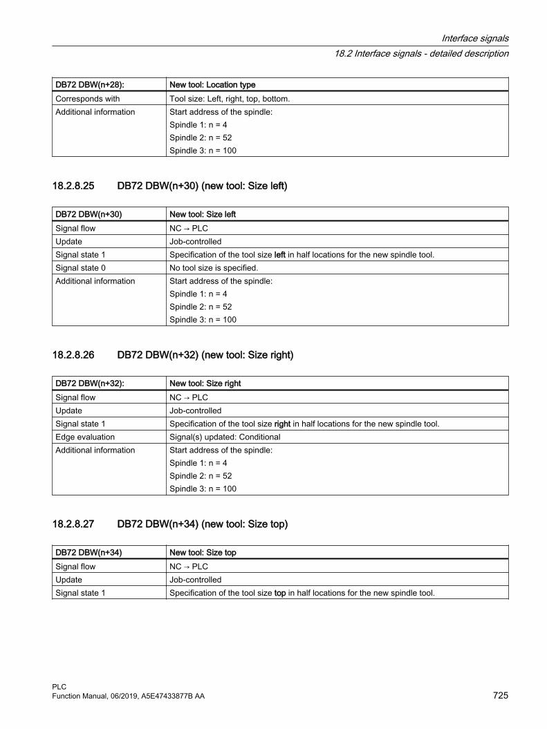
DB72 DBW(n+28): New tool: Location type Corresponds with Tool size: Left, right, top, bottom.Additional information Start address of the spindle:
Spindle 1: n = 4 Spindle 2: n = 52 Spindle 3: n = 100
18.2.8.25 DB72 DBW(n+30) (new tool: Size left)
DB72 DBW(n+30) New tool: Size leftSignal flow NC → PLCUpdate Job-controlledSignal state 1 Specification of the tool size left in half locations for the new spindle tool.Signal state 0 No tool size is specified.Additional information Start address of the spindle:
Spindle 1: n = 4 Spindle 2: n = 52 Spindle 3: n = 100
18.2.8.26 DB72 DBW(n+32) (new tool: Size right)
DB72 DBW(n+32): New tool: Size rightSignal flow NC → PLCUpdate Job-controlledSignal state 1 Specification of the tool size right in half locations for the new spindle tool.Edge evaluation Signal(s) updated: ConditionalAdditional information Start address of the spindle:
Spindle 1: n = 4 Spindle 2: n = 52 Spindle 3: n = 100
18.2.8.27 DB72 DBW(n+34) (new tool: Size top)
DB72 DBW(n+34) New tool: Size topSignal flow NC → PLCUpdate Job-controlledSignal state 1 Specification of the tool size top in half locations for the new spindle tool.
Interface signals18.2 Interface signals - detailed description
PLCFunction Manual, 06/2019, A5E47433877B AA 725

DB72 DBW(n+34) New tool: Size topSignal state 0 No tool size is specified.Additional information Start address of the spindle:
Spindle 1: n = 4 Spindle 2: n = 52 Spindle 3: n = 100
18.2.8.28 DB72 DBW(n+36) (new tool: Size bottom)
DB72 DBW(n+36) New tool: Size bottomSignal flow NC → PLCUpdate Job-controlledSignal state 1 Specification of the tool size bottom in half locations for the new spindle tool.Signal state 0 No tool size is specified.Additional information Start address of the spindle:
Spindle 1: n = 4 Spindle 2: n = 52 Spindle 3: n = 100
18.2.8.29 DB72 DBW(n+38) (tool status for new tool)
DB72 DBW(n+38) Tool status for new toolSignal flow NC → PLCUpdate Job-controlledSignal state 1 Bit 0: Tool in the buffer
Bit 1: disabled, but ignoreBit 2: Tool to be unloadedBit 3: Tool to be loadedBit 4: Master toolBit 5: ReservedBit 6: 1:1 exchangeBit 7: Manual toolBit 8: Active toolBit 9: Enable toolBit 10: Tool disabledBit 11: Measure toolBit 12: Prewarning limit reachedBit 13: Tool is being changedBit 14: Tool is fixed-location-codedBit 15: Tool was in use
Interface signals18.2 Interface signals - detailed description
PLC726 Function Manual, 06/2019, A5E47433877B AA

DB72 DBW(n+38) Tool status for new toolSignal state 0 No tool status specified.Additional information Start address of the spindle:
Spindle 1: n = 4 Spindle 2: n = 52 Spindle 3: n = 100
18.2.8.30 DB72 DBW(n+40) (new tool: internal T number of NC)
DB72 DBW(n+40) New tool: Internal T number of the NCSignal flow NC → PLCUpdate Job-controlledSignal state 1 Display of internal T number of NC for the new spindle tool.Signal state 0 No internal T number displayed.Additional information Start address of the spindle:
Spindle 1: n = 4 Spindle 2: n = 52 Spindle 3: n = 100
18.2.8.31 DB72 DBW(n+42) (buffer location of the old tool)
DB72 DBW(n+42) Buffer location of old toolSignal flow NC → PLCUpdate Job-controlledSignal state 1 If DB72 (n+0.4) = 1, the buffer location of the old tool must be entered here. This can be any
buffer magazine (also a gripper).Signal state 0 No buffer magazine location specified.Additional information Start address of the spindle:
Spindle 1: n = 4 Spindle 2: n = 52 Spindle 3: n = 100
18.2.8.32 DB72 DBW(n+44) (original magazine of the new tool)
DB72 DBW(n+44) Original magazine of new toolSignal flow NC → PLCUpdate Job-controlledSignal state 1 Owner magazine of the new tool
Corresponds to NC variables $A_MYMN[T no.] If the new tool is located in the magazine, then this value is identical with DB72 DBW(n+20). If the new tool is in the buffer magazine (e.g. gripper) then the magazine no. is entered here from where the tool originally came.
Interface signals18.2 Interface signals - detailed description
PLCFunction Manual, 06/2019, A5E47433877B AA 727

DB72 DBW(n+44) Original magazine of new toolSignal state 0 No original magazine specified.Additional information Start address of the spindle:
Spindle 1: n = 4 Spindle 2: n = 52 Spindle 3: n = 100
18.2.8.33 DB72 DBW(n+46) (original location of the new tool)
DB72 DBW(n+46) Original location of new toolSignal flow NC → PLCUpdate Job-controlledSignal state 1 Owner location of the new tool
Corresponds to NC variables $A_MYMLN[T no.]Signal state 0 No original location specified.Additional information Start address of the spindle:
Spindle 1: n = 4 Spindle 2: n = 52 Spindle 3: n = 100
18.2.9 DB73: Tool management, change in turret
18.2.9.1 DB73 DBX0.0 - 1.7 (active status of interfaces 1 - 16)
DB73 DBX0.0 - 1.7 Active status of interfaces 1-16Signal flow NC → PLCUpdate Job-controlledSignal state 1 Associated interface has a valid data set.Signal state 0 Operation for this interface has ended. Is reset by FC7.Edge evaluation Signal(s) updated: ConditionalAdditional information Start address of the turret:
Turret, 1: n = 4 Turret 2: n = 48 Turret 3: n = 92
18.2.9.2 DB73 DBX2.0 - 3.7 ("auto" acknowledgment of interfaces 1 - 16)
DB73 DBX2.0 - 3.7 "auto" acknowledgment of interfaces 1-16Signal flow NC → PLCUpdate Job-controlled
Interface signals18.2 Interface signals - detailed description
PLC728 Function Manual, 06/2019, A5E47433877B AA

DB73 DBX2.0 - 3.7 "auto" acknowledgment of interfaces 1-16Signal state 1 When setting (edge) the bit, the active command is acknowledged with status_1.Signal state 0 Operation for this interface has ended. Is reset by the basic program.Edge evaluation Signal(s) updated: ConditionalAdditional information Start address of the turret:
Turret, 1: n = 4 Turret 2: n = 48 Turret 3: n = 92
18.2.9.3 DB73 DBX(n+0).0 (command code: Obligatory change)
DB73 DBX(n+0).0 Command: Obligatory changeSignal flow NC → PLCUpdate Job-controlledSignal state 1 The new tool is fixed-location-coded.Signal state 0 The new tool is not fixed-location-coded.Additional information Start address of the turret:
Turret, 1: n = 4 Turret 2: n = 48 Turret 3: n = 92The bits in DBB(n+0) (obligatory change, execute change, ...) are not reset by the system. They are only current (up-to-date) if the corresponding interface bit in DBB0 is set to "1''. However, the bits can be reset by the user if necessary.
Corresponds with Position of participating tools
18.2.9.4 DB73 DBX(n+0).1 (command code: Execute change)
DB73 DBX(n+0).1 Command: Perform changeSignal flow NC → PLCUpdate Job-controlledSignal state 1 Execute tool change.Signal state 0 Do not change tool.Additional information Start address of the turret:
Turret, 1: n = 4 Turret 2: n = 48 Turret 3: n = 92The bits in DBB(n+0) (obligatory change, execute change, ...) are not reset by the system. They are only current (up-to-date) if the corresponding interface bit in DBB0 is set to "1''. However, the bits can be reset by the user if necessary.
Interface signals18.2 Interface signals - detailed description
PLCFunction Manual, 06/2019, A5E47433877B AA 729

18.2.9.5 DB73 DBX(n+0).3 (T0))
DB73 DBX(n+0).3 T0Signal flow NC → PLCUpdate Job-controlledSignal state 1 Indicates that T0 has been programmed.Signal state 0 Does not indicate that T0 has been programmed.Additional information Start address of the turret:
Turret, 1: n = 4 Turret 2: n = 48 Turret 3: n = 92The bits in DBB(n+0) (obligatory change, execute change, ...) are not reset by the system. They are only current (up-to-date) if the corresponding interface bit in DBB0 is set to "1''. However, the bits can be reset by the user if necessary.
18.2.9.6 DB73 DBX(n+1).0 ("auto" acknowledgment negative)
DB73 DBX(n+1).0 "auto" acknowledgment negativeSignal flow NC → PLCUpdate Job-controlledSignal state 1 The bit is only evaluated in conjunction with "auto" ackn. If it is set, then the auto acknowledge
is negative, i.e. with status_3.Signal state 0 The bit is not set.Additional information Start address of the turret:
Turret, 1: n = 4 Turret 2: n = 48 Turret 3: n = 92
18.2.9.7 DB73 DBX(n+1).7 (command: data in the extended range)
DB73 DBX(n+1).7 Command: Data in the extended rangeSignal flow NC → PLCUpdate Job-controlledSignal state 1 The signal is set if a tool is loaded into a multitool. DB73 contains the data of the multitool, the
data of the selected tool is available in DB1073. For T0 the signal is not set.
Signal state 0 The signal is not set if no tool is loaded into a multitool. Additional information Start address of the turret:
Turret, 1: n = 4 Turret 2: n = 48 Turret 3: n = 92
Interface signals18.2 Interface signals - detailed description
PLC730 Function Manual, 06/2019, A5E47433877B AA

18.2.9.8 DB73 DBB(n+2) (assigned channel)
DB73 DBB(n+2) Assigned channelSignal flow NC → PLCUpdate Job-controlledSignal state 1 Number of channel from which the T word was programmed.Signal state 0 Number of the channel is not assigned.Additional information Start address of the turret:
Turret, 1: n = 4 Turret 2: n = 48 Turret 3: n = 92
18.2.9.9 DB73 DBB(n+3) (tool management No.)
DB73 DBB(n+3) Tool management numberSignal flow NC → PLCUpdate Job-controlledSignal state 1 Associated tool management number (TO area) of channel.Signal state 0 Tool management is not assigned.Additional information Start address of the turret:
Turret, 1: n = 4 Turret 2: n = 48 Turret 3: n = 92
18.2.9.10 DB73 DBD(n+4) (user-definable parameter 0 (DInt))
DB73 DBD(n+4) User-definable parameter 0 (DInt)Signal flow NC → PLCUpdate Job-controlledSignal state 1 If you need to send a value to the PLC via the part program, the transfer can be programmed
with $P_VDITCP[0] = value. Parameters 0-2 are transferred with the T command.Signal state 0 No value is transferred to the PLC.Additional information Start address of the turret:
Turret, 1: n = 4 Turret 2: n = 48 Turret 3: n = 92
Interface signals18.2 Interface signals - detailed description
PLCFunction Manual, 06/2019, A5E47433877B AA 731

18.2.9.11 DB73 DBD(n+8) (user-definable parameter 1 (DInt))
DB73 DBD(n+8) User-definable parameter 1 (DInt)Signal flow NC → PLCUpdate Job-controlledSignal state 1 If you need to send a value to the PLC via the part program, the transfer can be programmed
with $P_VDITCP[1] = value.Signal state 0 No value is transferred to the PLCAdditional information Start address of the turret:
Turret, 1: n = 4 Turret 2: n = 48 Turret 3: n = 92
18.2.9.12 DB73 DBD(n+12) (user-definable parameter 2 (DInt))
DB73 DBD(n+12): User-definable parameter 2 (DInt)Signal flow NC → PLCUpdate Job-controlledSignal state 1 If you need to send a value to the PLC via the part program, the transfer can be programmed
with $P_VDITCP[2] = value.Signal state 0 No value is transferred to the PLCAdditional information Start address of the turret:
Turret, 1: n = 4 Turret 2: n = 48 Turret 3: n = 92
18.2.9.13 DB73 DBW(n+20) (magazine number of the new tool)
DB73 DBD(n+20) Magazine no. of new toolSignal flow NC → PLCUpdate Job-controlledSignal state 1 Magazine no. of the new tool, which should be processed.Signal state 0 There is no magazine number of the new tool.Additional information Start address of the turret:
Turret, 1: n = 4 Turret 2: n = 48 Turret 3: n = 92
Corresponds with DBW(n+22)
Interface signals18.2 Interface signals - detailed description
PLC732 Function Manual, 06/2019, A5E47433877B AA

18.2.9.14 DB73 DBW(n+22) (location number of the new tool to be loaded)
DB73 DBD(n+22) Location no. of new tool to be loaded at changeSignal flow NC → PLCUpdate Job-controlledSignal state 1 Location no. of the new tool, which should be processed.Signal state 0 There is no location number of the new tool.Additional information Start address of the turret:
Turret, 1: n = 4 Turret 2: n = 48 Turret 3: n = 92
Corresponds with DBW(n+20)
18.2.9.15 DB73 DBW(n+24) (magazine No. (target) for old tool to be removed)
DB73 DBW(n+24) Magazine No. (target) for old tool to be removedSignal flow NC → PLCUpdate Job-controlledSignal state 1 Number of magazine in which the tool to be removed at change will be placed.Signal state 0 No magazine No. is output.Corresponds with DBW(n+26)Additional information Start address of the spindle:
Spindle 1: n = 4 Spindle 2: n = 52 Spindle 3: n = 100
18.2.9.16 DB73 DBW(n+26) (location number of the old tool to be removed)
DB73 DBD(n+26) Location no. of old tool to be unloadedSignal flow NC → PLCUpdate Job-controlledSignal state 1 Location no. of the old tool (used up to now for machining).Signal state 0 No location number specified.Additional information Start address of the turret:
Turret, 1: n = 4 Turret 2: n = 48 Turret 3: n = 92
Interface signals18.2 Interface signals - detailed description
PLCFunction Manual, 06/2019, A5E47433877B AA 733

18.2.9.17 DB73 DBW(n+28) (new tool: Location type)
DB73 DBD(n+28) New tool: Location typeSignal flow NC → PLCUpdate Job-controlledSignal state 1 The location type of the new tool is entered here.Signal state 0 No location type of the new entry entered.Corresponds with Tool size: Left, right, top, bottomAdditional information Start address of the turret:
Turret, 1: n = 4 Turret 2: n = 48 Turret 3: n = 92
18.2.9.18 DB73 DBW(n+30) (new tool: Size left)
DB73 DBD(n+30) New tool: Size leftSignal flow NC → PLCUpdate Job-controlledSignal state 1 Specification of the tool size left in half locations for the new tool.Signal state 0 No tool size is specified.Additional information Start address of the turret:
Turret, 1: n = 4 Turret 2: n = 48 Turret 3: n = 92
18.2.9.19 DB73 DBW(n+32) (new tool: Size right)
DB73 DBD(n+32) New tool: Size rightSignal flow NC → PLCUpdate Job-controlledSignal state 1 Specification of the tool size right in half locations for the new toolSignal state 1 No tool size is specified.Additional information Start address of the turret:
Turret, 1: n = 4 Turret 2: n = 48 Turret 3: n = 92
Interface signals18.2 Interface signals - detailed description
PLC734 Function Manual, 06/2019, A5E47433877B AA

18.2.9.20 DB73 DBW(n+34) (new tool: Size top)
DB73 DBD(n+34) New tool: Size topSignal flow NC → PLCUpdate Job-controlledSignal state 1 Specification of the tool size top in half locations for the new toolSignal state 0 No tool size is specified.Additional information Start address of the turret:
Turret, 1: n = 4 Turret 2: n = 48 Turret 3: n = 92
18.2.9.21 DB73 DBW(n+36) (new tool: Size bottom)
DB73 DBD(n+36) New tool: Size bottomSignal flow NC → PLCUpdate Job-controlledSignal state 1 Specification of the tool size bottom in half locations for the new toolSignal state 0 No tool size is specified.Additional information Start address of the turret:
Turret, 1: n = 4 Turret 2: n = 48 Turret 3: n = 92
18.2.9.22 DB73 DBW(n+38) (tool status for new tool)
DB73 DBD(n+38) Tool status for new toolSignal flow NC → PLCUpdate Job-controlled
Interface signals18.2 Interface signals - detailed description
PLCFunction Manual, 06/2019, A5E47433877B AA 735

DB73 DBD(n+38) Tool status for new toolSignal state 1 Bit 0: Tool in the buffer
Bit 1: Locked, but ignoreBit 2: Tool to be unloadedBit 3: Tool to be loadedBit 4: Master toolBit 5: ReservedBit 6: 1:1 exchangeBit 7: Manual toolBit 8: Active toolBit 9: Enable toolBit 10: Tool disabledBit 11: Measure toolBit 12: Prewarning limit reachedBit 13: Tool is being changedBit 14: Tool is fixed-location-codedBit 15: Tool was in use
Signal state 0 No tool status displayed.Additional information Start address of the turret:
Turret, 1: n = 4 Turret 2: n = 48 Turret 3: n = 92
18.2.9.23 DB73 DBW(n+40) (new tool: Internal T no. of the NC)
DB73 DBD(n+40) New tool: Internal T no. of the NCSignal flow NC → PLCUpdate Job-controlledSignal state 1 Display internal T no. of the NC for the new tool. Tool management variables can be read/
written via FB2/FB3 using this T no.Signal state 0 No internal T number displayed.Additional information Start address of the turret:
Turret, 1: n = 4 Turret 2: n = 48 Turret 3: n = 92
18.2.9.24 DB73 DBW(n+42) (original location of the new tool in this turret magazine)
DB73 DBD(n+42) Original location of new tool in this turret magazineSignal flow NC → PLCUpdate Job-controlledSignal state 1
Interface signals18.2 Interface signals - detailed description
PLC736 Function Manual, 06/2019, A5E47433877B AA

DB73 DBD(n+42) Original location of new tool in this turret magazineSignal state 0 Additional information Start address of the turret:
Turret, 1: n = 4 Turret 2: n = 48 Turret 3: n = 92
18.2.10 DB1071: Tool management, load/unload magazine (multitool)
18.2.10.1 DB1071 DBW(n+0) (distance coding)
DB1071 DBW(n+0) Distance codingSignal flow NC → PLCUpdate Job-controlledSignal state 1 Type of distance coding of the multitool (corresponds to $TC_MTP_KD
1 = location number 2 = distance 3 = angle
Signal state 0 No distance codingAdditional information Starting address of loading/unloading points:
Loading/unloading point 1: n = 0 Loading/unloading point 2: n = 20 Loading/unloading point 3: n = 40 Loading/unloading point 4: n = 60
18.2.10.2 DB1071 DBW(n+2) (multitool location number)
DB1071 DBW(n+2) Multitool location numberSignal flow NC → PLCUpdate Job-controlledSignal state 1 Number of locations of the multitoolSignal state 0 No locations specified.Additional information Starting address of loading/unloading points:
Loading/unloading point 1: n = 0 Loading/unloading point 2: n = 20 Loading/unloading point 3: n = 40 Loading/unloading point 4: n = 60
Interface signals18.2 Interface signals - detailed description
PLCFunction Manual, 06/2019, A5E47433877B AA 737

18.2.10.3 DB1071 DBD(n+4) (multitool location distance)
DB1071 DBW(n+4) Multitool location distanceSignal flow NC → PLCUpdate Job-controlledSignal state 1 Distance of the MT location to be positioned from the reference location (real value), corre‐
sponding to the distance codingSignal state 1 No distance specified.Additional information Starting address of loading/unloading points:
Loading/unloading point 1: n = 0 Loading/unloading point 2: n = 20 Loading/unloading point 3: n = 40 Loading/unloading point 4: n = 60
18.2.10.4 DB1071 DBW(n+8) (multitool number)
DB1071 DBW(n+8) Multitool numberSignal flow NC → PLCUpdate Job-controlledSignal state 1 Internal T number of the multitool.Signal state 1 No internal T number specified.Additional information Starting address of loading/unloading points:
Loading/unloading point 1: n = 0 Loading/unloading point 2: n = 20 Loading/unloading point 3: n = 40 Loading/unloading point 4: n = 60
18.2.10.5 DB1071 DBW(n+10) (multitool location number)
DB1071 DBW(n+10) Multitool location numberSignal flow NC → PLCUpdate Job-controlledSignal state 1 Location number within the multitool (which the system positions to)Signal state 0 No location number specified.Additional information Starting address of loading/unloading points:
Loading/unloading point 1: n = 0 Loading/unloading point 2: n = 20 Loading/unloading point 3: n = 40 Loading/unloading point 4: n = 60
Interface signals18.2 Interface signals - detailed description
PLC738 Function Manual, 06/2019, A5E47433877B AA

18.2.10.6 DB1071 DBW(n+12) (toolholder)
DB1071 DBW(n+12) Tool holderSignal flow NC → PLCUpdate Job-controlledSignal state 1 Spindle or tool holder numberSignal state 0 No spindle or toolholder number specified.Additional information Starting address of loading/unloading points:
Loading/unloading point 1: n = 0 Loading/unloading point 2: n = 20 Loading/unloading point 3: n = 40 Loading/unloading point 4: n = 60
18.2.11 DB1072: Tool management, spindle (multitool)
18.2.11.1 DB1072 DBW(n+0) (distance coding)
DB1072 DBW(n+0) Distance codingSignal flow NC → PLCUpdate Job-controlledSignal state 1 Type of distance coding of the multitool (corresponds to $TC_MTP_KD)
1 = location number 2 = distance 3 = angle
Signal state 0 No distance coding specified.Additional information Start addresses of the spindles:
Spindle 1: n = 0 Spindle 2: n = 50 Spindle 3: n = 100
18.2.11.2 DB1072 DBW(n+2) (multitool location number)
DB1072 DBW(n+2) Multitool location numberSignal flow NC → PLCUpdate Job-controlledSignal state 1 Number of locations of the multitool
Interface signals18.2 Interface signals - detailed description
PLCFunction Manual, 06/2019, A5E47433877B AA 739

DB1072 DBW(n+2) Multitool location numberSignal state 0 No data regarding the number of locations.Additional information Start addresses of the spindles:
Spindle 1: n = 0 Spindle 2: n = 50 Spindle 3: n = 100
18.2.11.3 DB1072 DBW(n+4) (multitool location distance)
DB1072 DBW(n+4) Multitool location distanceSignal flow NC → PLCUpdate Job-controlledSignal state 1 Distance of the MT location to be positioned from the reference location (real value), corre‐
sponding to the distance codingSignal state 1 No data regarding the distance of the MT location to be positioned.Additional information Start addresses of the spindles:
Spindle 1: n = 0 Spindle 2: n = 50 Spindle 3: n = 100
18.2.11.4 DB1072 DBW(n+8) (multitool number (new tool))
DB1072 DBW(n+8) Multitool number (new tool)Signal flow NC → PLCUpdate Job-controlledSignal state 1 Internal T number of the (new) multitool.Signal state 0 No internal T number specified.Additional information Start addresses of the spindles:
Spindle 1: n = 0 Spindle 2: n = 50 Spindle 3: n = 100
18.2.11.5 DB1072 DBW(n+10) (multitool location number (new tool))
DB1072 DBW(n+10) Multitool location number (new tool)Signal flow NC → PLCUpdate Job-controlledSignal state 1 Location number within the multitool (where the new tool is located).
Interface signals18.2 Interface signals - detailed description
PLC740 Function Manual, 06/2019, A5E47433877B AA

DB1072 DBW(n+10) Multitool location number (new tool)Signal state 0 No location number specified.Additional information Start addresses of the spindles:
Spindle 1: n = 0 Spindle 2: n = 50 Spindle 3: n = 100
18.2.11.6 DB1072 DBW(n+12) (multitool number (old tool))
DB1072 DBW(n+12) Multitool number (old tool)Signal flow NC → PLCUpdate Job-controlledSignal state 1 Internal T number of the (old) multitool.
The T number is entered here if the preparation or the change to a tool is realized within the same multitool (which, due to a previous change, is located on the tool holder). It is identical with DB1072 DBW(n + 8)
Signal state 0 No internal T number of the multitool specified.Additional information Start addresses of the spindles:
Spindle 1: n = 0 Spindle 2: n = 50 Spindle 3: n = 100
18.2.11.7 DB1072 DBW(n+14) (multitool location number (old tool))
DB1072 DBW(n+14) Multitool location number (old tool)Signal flow NC → PLCUpdate Job-controlledSignal state 1 Location number within the multitool (where the old tool is located).
The location number - where the old tool is located - is entered here if the preparation or the change to a tool is realized within the same multitool (which, due to a previous change, is located on the tool holder).
Signal state 0 No multitool location number specified.Additional information Start addresses of the spindles:
Spindle 1: n = 0 Spindle 2: n = 50 Spindle 3: n = 100
18.2.11.8 DB1072 DBW(n+16) (new tool: Location type)
DB1072 DBW(n+16) New tool: Location typeSignal flow NC → PLCUpdate Job-controlled
Interface signals18.2 Interface signals - detailed description
PLCFunction Manual, 06/2019, A5E47433877B AA 741

DB1072 DBW(n+16) New tool: Location typeSignal state 1 Location type of the new tool (of the programmed tool in the multitool).Signal state 0 No location type specified.Additional information Start addresses of the spindles:
Spindle 1: n = 0 Spindle 2: n = 50 Spindle 3: n = 100
Corresponds with Tool size: Left, right, top, bottom
18.2.11.9 DB1072 DBW(n+18) (new tool: Size left)
DB1072 DBW(n+18) New tool: Size leftSignal flow NC → PLCUpdate Job-controlledSignal state 1 Specification of the tool size to the left in half locations of the new tool (of the programmed tool
in the multitool)Signal state 0 No tool size is specified.Additional information Start addresses of the spindles:
Spindle 1: n = 0 Spindle 2: n = 50 Spindle 3: n = 100
18.2.11.10 DB1072 DBW(n+20) (new tool: Size right)
DB1072 DBW(n+20) New tool: Size rightSignal flow NC → PLCUpdate Job-controlledSignal state 1 Specification of the tool size to the right in half locations of the new tool (of the programmed
tool in the multitool)Signal state 0 No tool size is specified.Additional information Start addresses of the spindles:
Spindle 1: n = 0 Spindle 2: n = 50 Spindle 3: n = 100
18.2.11.11 DB1072 DBW(n+22) (new tool: Size top)
DB1072 DBW(n+22) New tool: Size topSignal flow NC → PLCUpdate Job-controlledSignal state 1 Specification of the tool size to the top in half locations of the new tool (of the programmed tool
in the multitool)
Interface signals18.2 Interface signals - detailed description
PLC742 Function Manual, 06/2019, A5E47433877B AA

DB1072 DBW(n+22) New tool: Size topSignal state 0 No tool size is specified.Additional information Start addresses of the spindles:
Spindle 1: n = 0 Spindle 2: n = 50 Spindle 3: n = 100
18.2.11.12 DB1072 DBW(n+24) (new tool: Size bottom)
DB1072 DBW(n+24) New tool: Size bottomSignal flow NC → PLCUpdate Job-controlledSignal state 1 Specification of the tool size to the bottom in half locations of the new tool (of the programmed
tool in the multitool)Signal state 0 No tool size is specified.Additional information Start addresses of the spindles:
Spindle 1: n = 0 Spindle 2: n = 50 Spindle 3: n = 100
18.2.11.13 DB1072 DBW(n+26) (new tool status)
DB1072 DBW(n+26) Tool status for new tool:Signal flow NC → PLCUpdate Job-controlledSignal state 1 Tool status of the programmed tool in the multitool.
Corresponds to parameter $TC_TP8[T_No] Bit 0: Active tool Bit 1: Enable tool Bit 2: Tool disabled Bit 3: Measure tool Bit 4: Prewarning limit reached Bit 5: Tool is being changed Bit 6: Tool is fixed-location-coded Bit 7: Tool was in use Bit 8: Tool in the buffer Bit 9: Disabled, but ignore Bit 10: Tool to be unloaded Bit 11: Tool to be loaded Bit 12: Master tool Bit 13: Reserved Bit 14: 1:1 exchange Bit 15: Manual tool
Interface signals18.2 Interface signals - detailed description
PLCFunction Manual, 06/2019, A5E47433877B AA 743

DB1072 DBW(n+26) Tool status for new tool:Signal state 0 No tool status displayed.Additional information Start addresses of the spindles:
Spindle 1: n = 0 Spindle 2: n = 50 Spindle 3: n = 100
18.2.11.14 DB1072 DBW(n+28) (new tool: internal T number of the NC)
DB1072 DBW(n+28) New tool: Internal T number of the NCSignal flow NC → PLCUpdate Job-controlledSignal state 1 Display the internal T number of the NC for the new spindle tool (of the programmed tool in the
multitool).Signal state 0 No internal T number displayed.Additional information Start addresses of the spindles:
Spindle 1: n = 0 Spindle 2: n = 50 Spindle 3: n = 100
18.2.11.15 DB1072 DBW(n+30) (tool holder)
DB1072 DBW(n+30) Tool holderSignal flow NC → PLCUpdate Job-controlledSignal state 1 Spindle or toolholder number to which the change refers (the multitool that is to be changed).Signal state 0 No spindle or toolholder number specified.Additional information Start addresses of the spindles:
Spindle 1: n = 0 Spindle 2: n = 50 Spindle 3: n = 100
18.2.11.16 DB1072 DBW(n+32) (original magazine of the new tool)
DB1072 DBW(n+32) Original magazine of new toolSignal flow NC → PLCUpdate Job-controlled
Interface signals18.2 Interface signals - detailed description
PLC744 Function Manual, 06/2019, A5E47433877B AA

DB1072 DBW(n+32) Original magazine of new toolSignal state 1 Magazine that owns the new tool.
Corresponds to NC variables $A_MYMN[T no.] If the new tool is located in the magazine, then this value is identical with DB72 DBW(n+20). If the new tool is in the buffer magazine (e.g. gripper) then the magazine No. is entered here from where the tool originally came. The new tool has the same owner location as the multitool onto which it is loaded.
Signal state 0 No original magazine specified.Additional information Start addresses of the spindles:
Spindle 1: n = 0 Spindle 2: n = 50 Spindle 3: n = 100
18.2.11.17 DB1072 DBW(n+34) (original location of the new tool)
DB1072 DBW(n+34) Original location of new toolSignal flow NC → PLCUpdate Job-controlledSignal state 1 Location that owns the new tool.
Corresponds to NC variables $A_MYMLNT[T no.]If the new tool is located in the magazine, then this value is identical with DB72 DBW(n+20). If the new tool is in the buffer magazine (e.g. gripper) then the magazine No. is entered here from where the tool originally came. The new tool has the same owner location as the multitool onto which it is loaded.
Signal state 0 No original location specified.Additional information Start addresses of the spindles:
Spindle 1: n = 0 Spindle 2: n = 50 Spindle 3: n = 100
18.2.12 DB1073: Tool management, turret (multitool)
18.2.12.1 DB1073 DBW(n+0) (distance coding)
DB1073 DBW(n+0) Distance codingSignal flow NC → PLCUpdate Job-controlledSignal state 1 Type of distance coding of the multitool (corresponds to $TC_MTP_KD)
1 = location number 2 = distance 3 = angle
Interface signals18.2 Interface signals - detailed description
PLCFunction Manual, 06/2019, A5E47433877B AA 745

DB1073 DBW(n+0) Distance codingSignal state 0 No distance coding specified.Additional information Start addresses of the turrets:
Spindle 1: n = 0 Spindle 2: n = 50 Spindle 3: n = 100
18.2.12.2 DB1073 DBW(n+2) (multitool location number)
DB1073 DBW(n+2) Multitool location numberSignal flow NC → PLCUpdate Job-controlledSignal state 1 Number of locations of the multitoolSignal state 0 Number of locations of the multitool not displayed.Additional information Start addresses of the turrets:
Spindle 1: n = 0 Spindle 2: n = 50 Spindle 3: n = 100
18.2.12.3 DB1073 DBW(n+4) (multitool location distance)
DB1073 DBW(n+4) Multitool location distanceSignal flow NC → PLCUpdate Job-controlledSignal state 1 Distance of the MT location to be positioned from the reference location (real value). In ac‐
cordance with the distance coding.Signal state 0 No distance specified.Additional information Start addresses of the turrets:
Spindle 1: n = 0 Spindle 2: n = 50 Spindle 3: n = 100
18.2.12.4 DB1073 DBW(n+8) (multitool number (new tool))
DB1073 DBW(n+8) Multitool number (new tool)Signal flow NC → PLCUpdate Job-controlledSignal state 1 Internal T number of the (new) multitool.
Interface signals18.2 Interface signals - detailed description
PLC746 Function Manual, 06/2019, A5E47433877B AA

DB1073 DBW(n+8) Multitool number (new tool)Signal state 0 No internal T number of the multitool is specified.Additional information Start addresses of the turrets:
Spindle 1: n = 0 Spindle 2: n = 50 Spindle 3: n = 100
18.2.12.5 DB1073 DBW(n+10) (multitool location number (new tool))
DB1073 DBW(n+10) Multitool location number (new tool)Signal flow NC → PLCUpdate Job-controlledSignal state 1 Location number within the multitool (where the new tool is located).Signal state 1 No multitool location number specified.Additional information Start addresses of the turrets:
Spindle 1: n = 0 Spindle 2: n = 50 Spindle 3: n = 100
18.2.12.6 DB1073 DBW(n+12) (multitool number (old tool))
DB1073 DBW(n+12) Multitool number (old tool)Signal flow NC → PLCUpdate Job-controlledSignal state 1 Internal T number of the (old) multitool.
The T number is entered here if the preparation or the change to a tool is realized within the same multitool (which, due to a previous change, is located on the tool holder). It is identical with DB1072 DBW(n + 8)
Signal state 0 No internal T number of the multitool specified. Additional information Start addresses of the turrets:
Spindle 1: n = 0 Spindle 2: n = 50 Spindle 3: n = 100
18.2.12.7 DB1073 DBW(n+14) (multitool location number (old tool))
DB1073 DBW(n+14) Multitool location number (old tool)Signal flow NC → PLCUpdate Job-controlled
Interface signals18.2 Interface signals - detailed description
PLCFunction Manual, 06/2019, A5E47433877B AA 747

DB1073 DBW(n+14) Multitool location number (old tool)Signal state 1 Location number within the multitool (where the old tool is located).
The location number - where the old tool is located - is entered here if the preparation or the change to a tool is realized within the same multitool (which, due to a previous change, is located on the tool holder).
Signal state 0 No location number specified.Additional information Start addresses of the turrets:
Spindle 1: n = 0 Spindle 2: n = 50 Spindle 3: n = 100
18.2.12.8 DB1073 DBW(n+16) (new tool: Location type)
DB1073 DBW(n+16) New tool: Location typeSignal flow NC → PLCUpdate Job-controlledSignal state 1 Location type of the new tool (of the programmed tool in the multitool).Edge evaluation Signal(s) updated: ConditionalAdditional information Start addresses of the turrets:
Spindle 1: n = 0 Spindle 2: n = 50 Spindle 3: n = 100
Corresponds with Tool size: Left, right, top, bottom
18.2.12.9 DB1073 DBW(n+18) (new tool: Size left)
DB1073 DBW(n+18) New tool: Size leftSignal flow NC → PLCUpdate Job-controlledSignal state 1 Specification of the tool size to the left in half locations of the new tool (of the programmed tool
in the multitool)Signal state 1 No tool size is specified.Additional information Start addresses of the turrets:
Spindle 1: n = 0 Spindle 2: n = 50 Spindle 3: n = 100
18.2.12.10 DB1073 DBW(n+20) (new tool: Size right)
DB1073 DBW(n+20) New tool: Size rightSignal flow NC → PLCUpdate Job-controlled
Interface signals18.2 Interface signals - detailed description
PLC748 Function Manual, 06/2019, A5E47433877B AA

DB1073 DBW(n+20) New tool: Size rightSignal state 1 Specification of the tool size to the right in half locations of the new tool (of the programmed
tool in the multitool)Signal state 0 No tool size is specified.Additional information Start addresses of the turrets:
Spindle 1: n = 0 Spindle 2: n = 50 Spindle 3: n = 100
18.2.12.11 DB1073 DBW(n+22) (new tool: Size top)
DB1073 DBW(n+22) New tool: Size topSignal flow NC → PLCUpdate Job-controlledSignal state 1 Specification of the tool size to the top in half locations of the new tool (of the programmed tool
in the multitool)Signal state 0 No tool size is specified.Additional information Start addresses of the turrets:
Spindle 1: n = 0 Spindle 2: n = 50 Spindle 3: n = 100
18.2.12.12 DB1073 DBW(n+24) (new tool: Size bottom)
DB1073 DBW(n+24) New tool: Size bottomSignal flow NC → PLCUpdate Job-controlledSignal state 1 Specification of the tool size to the bottom in half locations of the new tool (of the programmed
tool in the multitool)Signal state 0 No tool size is specified.Additional information Start addresses of the turrets:
Spindle 1: n = 0 Spindle 2: n = 50 Spindle 3: n = 100
18.2.12.13 DB1073 DBW(n+26) (new tool status)
DB1073 DBW(n+26) Tool status for new tool:Signal flow NC → PLCUpdate Job-controlled
Interface signals18.2 Interface signals - detailed description
PLCFunction Manual, 06/2019, A5E47433877B AA 749

DB1073 DBW(n+26) Tool status for new tool:Signal state 1 Tool status of the programmed tool in the multitool
Corresponds to parameter $TC_TP8[T_No] Bit 0: Active tool Bit 1: Enable tool Bit 2: Tool disabled Bit 3: Measure tool Bit 4: Prewarning limit reached Bit 5: Tool is being changed Bit 6: Tool is fixed-location-coded Bit 7: Tool was in use Bit 8: Tool in the buffer Bit 9: Disabled, but ignore Bit 10: Tool to be unloaded Bit 11: Tool to be loaded Bit 12: Master tool Bit 13: Reserved Bit 14: 1:1 exchange Bit 15: Manual tool
Signal state 0 No tool status specified.Additional information Start addresses of the turrets:
Spindle 1: n = 0 Spindle 2: n = 50 Spindle 3: n = 100
18.2.12.14 DB1073 DBW(n+28) (new tool: internal T number of the NC)
DB1073 DBW(n+28) New tool: Internal T number of the NCSignal flow NC → PLCUpdate Job-controlledSignal state 1 Display the internal T number of the NC for the new spindle tool (of the programmed tool in the
multitool).Signal state 0 No internal T number displayed.Additional information Start addresses of the turrets:
Spindle 1: n = 0 Spindle 2: n = 50 Spindle 3: n = 100
18.2.12.15 DB1073 DBW(n+30) (tool holder)
DB1073 DBW(n+30) Tool holderSignal flow NC → PLCUpdate Job-controlled
Interface signals18.2 Interface signals - detailed description
PLC750 Function Manual, 06/2019, A5E47433877B AA

DB1073 DBW(n+30) Tool holderSignal state 1 Spindle or tool holder number to which the change refers (the multitool that is to be changed)Signal state 0 No spindle or toolholder number specified.Additional information Start addresses of the turrets:
Spindle 1: n = 0 Spindle 2: n = 50 Spindle 3: n = 100
18.2.12.16 DB1073 DBW(n+32) (original magazine of the new tool)
DB1073 DBW(n+32) Original magazine of new toolSignal flow NC → PLCUpdate Job-controlledSignal state 1 Magazine that owns the new tool.
Corresponds to NC variables $A_MYMN[T no.] If the new tool is located in the magazine, then this value is identical with DB72 DBW(n+20). If the new tool is in the buffer (e.g. gripper), then the magazine No. is entered here from where the tool originally came. The new tool has the same owner location as the multitool onto which it is loaded.
Signal state 0 Magazine that owns the new tool not specified.Additional information Start addresses of the turrets:
Spindle 1: n = 0 Spindle 2: n = 50 Spindle 3: n = 100
18.2.12.17 DB1073 DBW(n+34) (original location of the new tool)
DB1073 DBW(n+34) Original location of new toolSignal flow NC → PLCUpdate Job-controlledSignal state 1 Location that owns the new tool.
Corresponds to NC variables $A_MYMLNT[T no.] If the new tool is located in the magazine, then this value is identical with DB72 DBW(n+20). If the new tool is in the buffer magazine (e.g. gripper), the number of the magazine from which the tool originally came is entered here. The new tool has the same owner location as the multitool onto which it is loaded.
Signal state 0 Location that owns the new tool not specified.Additional information Start addresses of the turrets:
Spindle 1: n = 0 Spindle 2: n = 50 Spindle 3: n = 100
Interface signals18.2 Interface signals - detailed description
PLCFunction Manual, 06/2019, A5E47433877B AA 751

Interface signals18.2 Interface signals - detailed description
PLC752 Function Manual, 06/2019, A5E47433877B AA

Appendix AA.1 Overview
PLCFunction Manual, 06/2019, A5E47433877B AA 753

AppendixA.1 Overview
PLC754 Function Manual, 06/2019, A5E47433877B AA

Index
AActivation
from machine control panel, hand-held unit, 91AG_SEND, AG_RECV, 81
CConcurrent axes, 79Cyclic operation, 73
DData block DB, 307Data exchange
with operator panel, 51Data interface, 55DB10
Analog NC inputs and outputs, 350Collision avoidance: Activate protection area, 351Collision avoidance:protection area active, 351DBB194 - 208, 474DBW148 - 162, 467DBW170 - 184, 469, 470DBW210 - 224, 474, 475DBX0.0 - 7, 434, 435DBX1.0 - 7, 435DBX100.0 - 4, 444DBX100.5, 444, 445DBX100.6, 445DBX100.7, 446DBX101.0 - 4, 446DBX101.5, 446DBX101.6, 446DBX101.7, 447DBX102.0 - 4, 447DBX102.5, 447DBX102.6, 447DBX102.7, 447DBX103.0, 447DBX103.5, 447, 448DBX103.6, 448DBX103.7, 448DBX104.3, 93DBX104.4, 93DBX104.7, 77, 448DBX106.1, 449
DBX107.0 - 1, 449DBX107.6, 449DBX108.3, 450DBX108.5, 450DBX108.6, 450DBX108.7, 450, 451DBX109.0, 451DBX109.5, 451DBX109.6, 452DBX109.7, 452DBX110.0 - 113.7, 452, 453DBX114.0 - 117.7, 453DBX122.0 - 7, 454DBX123.0 - 7, 454DBX124.0 - 7, 454, 455DBX125.0 - 7, 455DBX126.0 - 7, 455, 456DBX127.0 - 7, 456DBX128.0 - 7, 456DBX129.0 - 7, 457DBX130.0 - 7, 457DBX131.0 - 7, 457, 458DBX132.0 - 7, 458DBX133.0 - 7, 459DBX134.0 - 7, 459DBX135.0 - 7, 460DBX136.0 - 7, 460, 461DBX137.0 - 7, 461DBX138.0 - 7, 461, 462DBX139.0 - 7, 462DBX140.0 - 7, 463DBX141.0 - 7, 463, 464DBX142.0 - 7, 464DBX143.0 - 7, 464, 465DBX144.0 - 7, 465DBX145.0 - 7, 466DBX146.0 - 7, 466DBX147.0 - 7, 467DBX166.0 - 7, 467, 468DBX167.0 - 7, 468, 469DBX168.0 - 7, 469DBX186.0 - 7, 470DBX187.0 - 7, 470, 471DBX188.0 - 7, 471DBX189.0 - 7, 471, 472DBX190.0 - 7, 472DBX191.0 - 7, 472, 473DBX192.0 - 7, 473DBX193.0 - 7, 473, 474
PLCFunction Manual, 06/2019, A5E47433877B AA 755

DBX226.0 - 233.7, 475DBX234.0 - 241.7, 476DBX245.0 - 5, 476, 477DBX4.0 - 7, 435, 436DBX5.0 - 7, 436DBX56.1, 438DBX56.2, 438DBX56.4 - 7, 438, 439DBX58.0 - 7, 439, 440DBX6.0 - 7, 436, 437DBX60.0 - 7, 440, 441DBX64.0 - 7, 441DBX7.0 - 7, 437DBX92.0, 76DBX92.1, 76DBX92.2, 76DBX92.4, 76DBX92.5, 76DBX92.6, 76DBX93.0 ... 7, 441, 442DBX97.0 - 3, 442, 443DBX98.0 - 3, 443DBX99.0 - 3, 443External analog NC inputs, 347External analog NC outputs, 348External digital NC inputs, 345External digital NC inputs and outputs, 349External digital NC outputs, 346General signals from the NC, 344General signals to the NC, 340Handwheel signals from the NC, 352Onboard inputs and outputs from the NC, 341Onboard NC inputs/outputs, 339Signals from the operating software, 342Signals from the robot, 353Signals to the robot, 353
DB1000Energy-saving profiles, 424
DB1001SENTRON PAC, 426SENTRON PAC auxiliary devices, 428
DB1002Spindle temperature sensors, 429
DB1071DBW(n+0), 737DBW(n+10), 738DBW(n+12), 739DBW(n+2), 737DBW(n+4), 738DBW(n+8), 738Multitool magazine interface, 431
DB1072DBW(n+0), 739DBW(n+10), 740, 741DBW(n+12), 741DBW(n+14), 741DBW(n+16), 741, 742DBW(n+18), 742DBW(n+2), 739, 740DBW(n+20), 742DBW(n+22), 742, 743DBW(n+24), 743DBW(n+26), 743, 744DBW(n+28), 744DBW(n+30), 744DBW(n+32), 744, 745DBW(n+34), 745DBW(n+4), 740DBW(n+8), 740Multitool spindle interface, 432
DB1073DBW(n+0), 745, 746DBW(n+10), 747DBW(n+12), 747DBW(n+14), 747, 748DBW(n+16), 748DBW(n+18), 748DBW(n+2), 746DBW(n+20), 748, 749DBW(n+22), 749DBW(n+24), 749DBW(n+26), 749, 750DBW(n+28), 750DBW(n+30), 750, 751DBW(n+32), 751DBW(n+34), 751DBW(n+4), 746DBW(n+8), 746, 747Multitool turret interface, 433
DB11DBX0.0, 477DBX0.1, 477, 478DBX0.2, 478DBX0.4, 478DBX0.5, 479DBX0.6, 479, 480DBX0.7, 480DBX1.0, 480, 481DBX1.1, 481DBX1.2, 481DBX1.6, 481, 482DBX1.7, 482DBX4.0, 483
Index
PLC756 Function Manual, 06/2019, A5E47433877B AA

DBX4.1, 483DBX4.2, 483DBX5.0, 483, 484DBX5.1, 484DBX5.2, 484DBX6.0, 484DBX6.1, 485DBX6.2, 485DBX6.3, 485DBX6.7, 486DBX7.0, 486DBX7.1, 486DBX7.2, 486, 487Mode signals 1 from HMI, 355Mode signals 1 from the NC, 354Mode signals 2 from HMI, 356Mode signals 2 from the NC, 356Mode signals 2 to the NC, 355Mode signals to the NC, 354
DB18Additional data areas, 359Data area/errors, 357DBB36.0, 487DBB36.1, 487DBB38.0 - 41.7, 487, 488DBB42.0 - 45.7, 488DBB46.0 - 49.7, 488, 489Extended additional data areas, 364Extended data area / errors, 362F_SENDDP receiver, 360, 367F_SENDDP sender, 360, 365Parameterization part, 357SPL user data, 361
DB19DBB10, 492DBB15, 493DBB16, 493, 494DBB17, 494, 495DBB22, 496DBB27, 499, 500DBB33, 109DBB33 - 35, 501DBB36, 109, 502DBB6, 491DBB7, 491DBB8, 492DBW24, 496DBX0.0, 489DBX0.1, 489, 490DBX0.2, 490DBX0.3, 490DBX0.4, 491
DBX0.7, 491DBX13.5, 492DBX13.6, 492DBX13.7, 492DBX14.0 - 6, 493DBX14.7, 493DBX20.1, 495DBX20.3, 495DBX20.4, 495DBX20.6, 496DBX20.7, 496DBX26, 497, 498DBX26.1, 497DBX26.2, 497DBX26.5, 498DBX26.6, 498, 499DBX26.7, 499DBX32.0 - .5, 109, 500DBX32.6, 109, 501DBX32.7, 109, 501Signals from the operator panel, 373Signals to the operator panel, 371Signals to/from operator panel, sidescreen, 377
DB19, signals from the operator panel, 377DB2
Axis ranges, 322, 333Channel range 1, 317, 326Channel range 10, 333Channel range 2, 318, 327Channel range 3, 318, 328Channel range 4, 319, 329Channel range 5, 320, 329Channel range 6, 320, 330Channel range 7, 321, 331Channel range 8, 322, 331Channel range 9, 332User ranges, 323, 335
DB20NC machine data, 378
DB21DBB129, 569DBB140, 569
DB21 - DB30Change signals from the channel, 387Control signals from the geometry axes, 385Control signals from the operating software, 383Control signals from the PLC, 383Control signals to the geometry axes, 381D function signals, 389DL function signals, 389F function signals, 390G function signals, 392
Index
PLCFunction Manual, 06/2019, A5E47433877B AA 757

H function signals, 390Job-controlled signals, 394, 396M function signals, 388M function signals, dynamic, 391Protection zone signals from the channel, 393S function signals, 388Signals for the tool management functions, 399Signals from channel, 400Signals from the orientation axes, 398Signals from/to channel, 402Signals to channel, 401Signals to the orientation axes, 396Status signal from the channel, 383T function signals, 389
DB21, ...DBB158 - 193, 569, 570DBB208 - 271, 570, 571DBB376, 592, 593DBB392, 597DBB4, 512, 513, 514DBB5, 514, 515, 516DBB58, 566DBB60 - 64, 567DBB60 - 65, 566DBB66 - 67, 567DBB68 - 97, 567, 568DBB98 - DBB115, 568DBW118 or DBD118, 568DBX0.1, 502DBX0.2, 503DBX0.3, 503DBX0.4, 503, 504DBX0.5, 504DBX0.6, 504, 505DBX1.0, 505DBX1.2, 506DBX1.3, 506DBX1.4, 506, 507DBX1.5, 507DBX1.6, 507, 508DBX1.7, 508, 509DBX10.0 - 11.1, 524DBX12.0 - 2, 524, 525DBX12.3, 525, 526DBX12.4, 526DBX12.5, 526, 527DBX12.6 - 7, 527, 528, 529DBX13.0 - 6, 529, 530DBX15.0, 530DBX16.0 - 2, 530DBX16.3, 525, 526DBX16.4, 531
DBX16.5, 531DBX16.6 - 7, 531DBX17.0 - 6, 531DBX19.0, 531DBX194.0 - 7 - DBX206.0 - 3, 570DBX2.0 - 7, 509, 510DBX20.0 - 2, 531DBX20.3, 525, 526DBX20.4, 531DBX20.5, 532DBX20.6 - 7, 532DBX21.0 - 6, 532DBX23.0, 532DBX24.3, 532DBX24.4, 533DBX24.5, 533DBX24.6, 534DBX25.3, 534, 535DBX25.7, 535, 536DBX26.0 ... 7, 536, 537DBX272.0 - 273.1, 571DBX274.0 - 275.1, 572DBX276.0 - 277.1, 572DBX278.0 - 279.1, 573DBX280.1, 573DBX281.1, 573, 574DBX29.0 - 3, 537, 538DBX29.4, 538DBX29.5, 538DBX29.6, 539DBX29.7, 539DBX3.0, 510DBX3.1, 510, 511DBX3.2, 511DBX3.3, 511DBX3.4, 511, 512DBX3.5, 512DBX30.0 - 2, 540DBX30.3, 540, 541DBX30.4, 541DBX30.5, 541DBX30.6, 542DBX300.0 - 307.7, 574DBX308.0 - 315.7, 574DBX31.0 - 2, 542, 543DBX31.4, 543DBX31.5, 544DBX317.1, 574DBX317.6, 575DBX317.7, 575DBX318.0, 575DBX318.1, 576
Index
PLC758 Function Manual, 06/2019, A5E47433877B AA

DBX318.2, 576DBX318.3, 576, 577DBX318.5, 577DBX319.0, 577, 578DBX319.1 - 3, 578DBX319.5, 579DBX32.1, 544DBX32.2, 544DBX32.3, 545DBX32.4, 545DBX32.5, 545DBX32.6, 546DBX320.0 - 2, 579, 580DBX320.4, 580, 581DBX320.5, 581DBX320.6 - 7, 581, 582, 583DBX321.0 - 6, 583, 584DBX323.0, 584DBX324.0 - 2, 584DBX324.4, 584DBX324.5, 585DBX324.6 - 7, 585DBX325.0 - 6, 585DBX327.0, 585DBX328.0 - 2, 585DBX328.4, 585DBX328.5, 585DBX328.6 - 7, 586DBX329.0 - 6, 586DBX33.0, 546DBX33.3, 547DBX33.4, 547DBX33.5, 547, 548DBX33.6, 549DBX33.7, 549DBX331.0, 586DBX332.0 - 2, 586, 587DBX332.4 - 5, 587, 588DBX332.6 - 7, 588, 589DBX333.0 - 6, 589DBX336.0 - 2, 589DBX336.4 - 5, 590DBX336.6 - 7, 590DBX337.0 - 6, 590DBX340.0 - 2, 590DBX340.4 - 5, 590DBX340.6 - 7, 590DBX341.0 - 6, 590DBX344.0, 591DBX344.1, 591DBX344.2, 591, 592DBX344.3, 592
DBX35.0, 550DBX35.1, 550, 551DBX35.2, 551, 552DBX35.3, 552DBX35.4, 552, 553DBX35.5, 553DBX35.6, 554DBX35.7, 554, 555DBX36.2, 555DBX36.3, 555DBX36.4, 556DBX36.5, 556DBX36.6, 556DBX36.7, 557DBX37.0 - 2, 557DBX37.3, 558DBX37.4, 558DBX37.5, 558, 559DBX37.6, 559DBX37.7, 560DBX377.0, 593DBX377.4, 593DBX377.5, 593, 594DBX377.6, 594DBX378.0, 594DBX378.1, 594DBX38.0, 560DBX38.1, 560, 561DBX384.0, 595DBX385.0 - 7, 595DBX386.0 - 7, 595DBX387.0 - 7, 596DBX39.1, 561DBX39.5, 561, 562DBX390.0 - 7, 596DBX391.0 - 7, 596, 597DBX40.0 - 2, 562DBX40.4 - 5, 563DBX40.6 - 7, 563, 564DBX41.0 - 6, 564DBX43.0, 564, 565DBX46.0 - 2, 565DBX46.4 - 5, 565DBX46.6 - 7, 565DBX47.0 -.6, 565DBX49.0, 565DBX52.0 - 2, 566DBX52.4 - 5, 566DBX52.6 - 7, 566DBX53.0 - 6, 566DBX55.0, 566DBX59.0 - 4, 567
Index
PLCFunction Manual, 06/2019, A5E47433877B AA 759

DBX6.0, 516, 517DBX6.1, 517DBX6.2, 518DBX6.4, 518DBX6.6, 519DBX6.7, 519DBX7.0, 519, 520DBX7.1, 520DBX7.2, 520, 521DBX7.3, 521DBX7.4, 522DBX7.7, 522, 523DBX8.0 - 9.1, 523
DB31DBX34.0 - 1, 650
DB31 - DB61Axis signals: Safety Control Channel (SCC), 416Safety Info Channel (SIC), 416Signals from axis/spindle, 408Signals to the axis/spindle, 403
DB31, ...DBB0, 598, 599, 600DBB19, 635, 636, 637DBB68, 666DBB8, 622DBD78, 674, 675DBD88, 684DBW134, 706, 707DBW136, 707DBW86, 683DBX1.0, 600DBX1.1, 601DBX1.2, 601DBX1.3, 602, 603, 604, 605DBX1.4, 605DBX1.5 - DBX1.6, 606, 607, 608DBX1.7, 608, 609DBX10.0, 623, 624DBX100.2, 700, 701DBX100.3, 701DBX100.4, 701DBX100.5, 701DBX100.6, 701, 702DBX100.7, 702DBX102.5, 702DBX102.6, 702, 703DBX104.0 / 107.6, 703DBX12.0, 624DBX12.1, 624DBX12.2, 625DBX12.3, 625DBX12.4, 625
DBX12.7, 625, 626DBX128.0, 703DBX128.1, 704DBX13.0 - 2, 626DBX13.3, 626, 627DBX130.0 - 4, 704DBX132.0, 704, 705DBX132.1, 705DBX132.4, 705DBX132.5, 705, 706DBX138.4, 708DBX138.5, 708DBX14.0, 627DBX14.1, 628DBX16.0 - DBX16.2, 628, 629DBX16.3, 629, 630DBX16.4, 630DBX16.5, 630, 631DBX16.7, 631DBX17.4, 631DBX17.5, 631, 632DBX17.6, 632DBX18.4, 632, 633DBX18.5, 633DBX18.6, 633, 634DBX18.7, 634DBX2.0, 609DBX2.1, 609, 610, 611DBX2.2, 611, 612DBX2.3, 613DBX2.4 - 7, 613DBX20.1, 637, 638DBX21.0 - 4, 638DBX21.5, 639DBX21.6, 639DBX21.7, 640DBX22.0, 640DBX22.1, 640DBX22.3 - 4, 640, 641DBX23.0 - 2, 641DBX23.4, 641DBX24.1, 641, 642DBX24.2, 642DBX24.3, 642, 643DBX24.4, 643DBX24.5, 643, 644DBX24.7, 644DBX26.4, 644, 645DBX28.0, 645DBX28.1, 645, 646DBX28.2, 646, 647DBX28.3, 647
Index
PLC760 Function Manual, 06/2019, A5E47433877B AA

DBX28.4, 647DBX28.5, 648DBX28.6, 648DBX28.7, 649DBX3.0, 614DBX3.1, 614DBX3.2 - 5, 615DBX3.6, 616DBX31.5, 649DBX33.2, 546, 547DBX4.0 - 2, 616, 617DBX4.3, 617, 618DBX4.4, 618, 619DBX4.5, 619DBX4.6 - 7, 619, 620DBX5.0 - 6, 620, 621DBX60.0, 650DBX60.1, 651DBX60.2, 651DBX60.3, 651, 652DBX60.4, 652DBX60.5, 653DBX60.6, 653DBX60.7, 654DBX61.0, 654DBX61.1, 655DBX61.2, 655DBX61.3, 655, 656DBX61.4, 656, 657DBX61.5, 657DBX61.6, 657, 658DBX61.7, 658DBX62.0, 658DBX62.1, 658, 659DBX62.2, 659DBX62.3, 659, 660DBX62.4, 660DBX62.5, 660DBX62.7, 660DBX63.0, 661DBX63.1, 661DBX63.2, 661, 662DBX63.3, 662DBX64.0 - 2, 662, 663DBX64.4 - 5, 663, 664DBX64.6 - 7, 664DBX65.0 - 6, 664, 665DBX66.0, 665DBX67.0, 665, 666DBX69.0 - 2, 666, 667DBX7.0, 621, 622DBX70.0, 667
DBX70.1, 668DBX70.2, 668, 669DBX71.4, 669DBX71.5, 669, 670DBX72.0, 670DBX74.4, 670DBX75.0 - 2, 671DBX75.3 - 5, 671DBX75.6, 672DBX75.7, 672DBX76.0, 672DBX76.4, 673DBX76.5, 673DBX76.6, 673, 674DBX77.0, 674DBX82.0 - 2, 675DBX82.3, 675, 676DBX83.0, 676DBX83.1, 676, 677DBX83.2, 678DBX83.3, 678DBX83.5, 679DBX83.6, 679DBX83.7, 679, 680DBX84.1, 680DBX84.3, 680DBX84.4, 681DBX84.5, 681DBX84.6, 681, 682DBX84.7, 682DBX85.0, 682DBX85.5, 682, 683DBX9.0 - 2, 623DBX9.3, 623DBX92.1, 684, 685DBX93.0 - 4, 685DBX93.5, 685, 686DBX93.6, 686DBX93.7, 687DBX94.0, 687DBX94.1, 688DBX94.2, 688, 689DBX94.3, 689DBX94.4, 690DBX94.5, 690, 692, 693DBX94.6, 691DBX94.7, 691DBX95.1, 691, 692DBX95.2, 692DBX95.3, 692DBX96.2, 693DBX96.3, 693
Index
PLCFunction Manual, 06/2019, A5E47433877B AA 761

DBX96.4, 693, 694DBX96.5, 694DBX96.7, 694DBX97.0, 695DBX97.1, 695DBX97.2, 695, 696DBX97.3, 696DBX98.0, 696, 697DBX98.1, 697DBX98.2, 697, 698DBX98.4, 698DBX98.5, 698, 699DBX98.6, 699DBX99.0, 699DBX99.1, 700DBX99.3, 700
DB71DBB(n+2), 712DBB(n+3), 712, 713DBW(n+16), 713DBW(n+18), 713DBW(n+20), 713, 714DBW(n+22), 714DBW(n+24), 714, 715DBW(n+26), 715DBX(n+0).0, 709DBX(n+0).1, 709, 710DBX(n+0).2, 710DBX(n+0).3, 710DBX(n+0).4, 711DBX(n+0).5, 711DBX(n+1).0, 711, 712DBX(n+1).7, 712DBX(n+28).0, 715DBX0.0 - 1.7, 708DBX2.0 - 3.7, 709Magazine interface, 417
DB72DBB(n+2), 721DBB(n+3), 721DBD(n+12), 722DBD(n+4), 721, 722DBD(n+8), 722DBW(n+16), 722, 723DBW(n+18), 723DBW(n+20), 723DBW(n+22), 723, 724DBW(n+24), 724DBW(n+26), 724DBW(n+28), 724, 725DBW(n+30), 725DBW(n+32), 725
DBW(n+34), 725, 726DBW(n+36), 726DBW(n+38), 726, 727DBW(n+40), 727DBW(n+42), 727DBW(n+44), 727, 728DBW(n+46), 728DBX(n+0).0, 716, 717DBX(n+0).1, 717DBX(n+0).2, 717, 718DBX(n+0).3, 718DBX(n+0).4, 718, 719DBX(n+0).5, 719DBX(n+0).6, 719, 720DBX(n+0).7, 720DBX(n+1).0, 720DBX(n+1).7, 721DBX0.0-1.7, 716DBX2.0-3.7, 716Spindle interface, 419
DB73DBB(n+2), 731DBB(n+3), 731DBD(n+12), 732DBD(n+20), 732DBD(n+22), 733DBD(n+26), 733DBD(n+28), 734DBD(n+30), 734DBD(n+32), 734DBD(n+34), 735DBD(n+36), 735DBD(n+38), 735, 736DBD(n+4), 731DBD(n+40), 736DBD(n+42), 736, 737DBD(n+8), 732DBW(n+24), 733DBX(n+0).0, 729DBX(n+0).1, 729DBX(n+0).3, 730DBX(n+1).0, 730DBX(n+1).7, 730DBX0.0 - 1.7, 728DBX2.0 - 3.7, 728, 729Turret interface, 421
DB77MCP and HHU, 423
Direct keysAddress, 93Alarms, 94OPs at Ethernet bus, 93
Index
PLC762 Function Manual, 06/2019, A5E47433877B AA

EEthernet
connection, 92
FFB1 RUN_UP (basic program, startup section), 149FB10 Safety relay, 216FB11 Brake test, 218FB2 GET (Read NC Variable), 157FB29 Signal recorder and data trigger diagnostics, 224FB3 PUT (write NC variables), 165FB4 PI_SERV (PI services), 173
Available PI services, 177, 178FB5 GETGUD (read GUD variable), 202FB7 PI_SERV2 (PI services), 210FB9 MzuN (operator panel switchover), 211FC10 AL_MSG, 247FC1005 AG_SEND, 299FC1006 AG_RECV, 300FC12 AUXFU, 249FC13 BHGDisp, 250FC17 YDelta, 254FC18 SpinCtrl, 257FC19 MCP_IFM, 267FC2 GP_HP (basic program, cyclic section), 227FC21 Transfer, 275FC22 TM_DIR, 283FC24 MCP_IFM2, 285FC25 MCP_IFT, 289FC26 HPU_MCP, 293FC3 GP_PRAL (basic program, alarmdriven section), 229FC5 GP_DIAG (basic program, diagnostics), 231FC6 TM_TRANS2, 233FC7 TM_REV, 234FC8 TM_TRANS, 238FC9 ASUP, 244Function block FB, 305Function block FC, 306Function interface, 56
HHandheld unit
HHU / HT 2, 312HT 10, 315, 316HT 8, 314
Hardware interrupt, 76HMI monitor, 123
IInterface
MCP/PLC and HHU/PLC, 53PLC/HMI, 53, 62PLC/HMI messages, 62PLC/MCP, 68PLC/NC, 55
Interface signals"auto" acknowledgment negative, 711, 712, 720, 730"auto" acknowledgment of interfaces 1 - 16, 709, 728, 729"auto" acknowledgment of interfaces 1-16, 716"Silent" ASUB is active, 594Acceleration alarm threshold reached, 699Accept external work offset, 614Acknowledge Emergency Stop, 438Acknowledge fixed stop reached, 601Acknowledgement of synchronized actions disabled, 573, 574Action block active, 545Activate associated auxiliary function, 541Activate contour handwheel, 540Activate dry run feedrate (DRY), 504, 505Activate fixed feedrate 1 - 4, machine axes, 615Activate fixed feedrate 1 - 4, path/geometry axes, 537, 538Activate handwheel, 616, 617Activate handwheel offset (DRF), 503Activate M01, 504Activate machine-related protection zone 1 - 10, 523, 524Activate program test, 628, 704Activate program test (PRT), 508, 509Activate PTP travel, 538Activate referencing, 505Activate single block, 503, 504Activate skip block, 509, 510Activate travel to fixed stop, 660Active G command of group 1 to 60, 570, 571Active infeed axes, 703Active JOG mode, 485Active machine function, 664, 665Active MDI mode, 485Active position controller parameter set, 666, 667Active REPOS mode, 578Active spindle mode, control mode, 682Active spindle mode, oscillation mode, 681, 682
Index
PLCFunction Manual, 06/2019, A5E47433877B AA 763

Active spindle mode, positioning mode, 681Active spindle mode: Synchronous mode, 681Active status of interface 1- 16, 728Active status of interfaces 1- 16, 708Active status of interfaces 1-16, 716Actual direction of rotation clockwise, 679, 680Actual gear stage A to C, 628, 629Actual screen number, 496Actual value coupling, 697, 698Actual values in the WCS, 491Air temperature alarm, 452All axes stationary, 555All axes that have to be referenced are referenced, 555All channels in the "Reset" state, 486Analog measured value of the clamping system, 707Analog NC input 1: Setting value, 467Analog NC inputs 1 - 8: Actual value, 474Analog NC inputs 1 - 8: Lock, 466Analog NC inputs 1 - 8: Target, 467Analog NC outputs 1 - 8: Overwrite, 467, 468Analog NC outputs 1 - 8: Setpoint, 441, 474, 475Analog NC outputs 1 - 8: Setting value, 469, 470Analog NC outputs 1 - 8: Target, 468, 469Analog spindle 1, utilization in percent, 491Analog spindle 2, utilization in percent, 491Approach block active, 545Assigned channel, 712, 721, 731Associated auxiliary function is active, 577Associated auxiliary function selected, 533ASUB is active, 594ASUB is stopped, 575AT box ready, 447, 448AUTOMATIC mode, 477AUTOMATIC mode active, 484AUTOMATIC mode selected, 483Axis accelerates, 700Axis container: Rotation active, 660Axis number handwheel 1, 444Axis number handwheel 2, 446Axis number handwheel 3, 447Axis stop active, 661, 662Axis/spindle disable, 602, 603, 604, 605Axis/spindle disable active, 662Axis/spindle exchange request, 622Axis/spindle stationary, 656, 657Axis-specific alarm, 655Block search active, 547Block search via program test is active, 576Brighten screen, 489Buffer location of old tool, 727
Buffer magazine no. (fixed value 9998); target position for new tool, 722, 723Cancel alarm deleted, 495Change gear stage, 675, 676Change reversal point, 647Channel is ready, 556Channel number, 492Channel number for geometry axis, handwheel 1, 442, 443Channel number for geometry axis, handwheel 2, 443Channel number for geometry axis, handwheel 3, 443Channel state active, 553Channel state interrupted, 554Channel state reset, 554, 555Channel-specific NC alarm active, 556Channel-specific protection zone 1 - 10 violated, 573Clamping in progress, 613Clearance control (CLC):, 558Clearance control (CLC): Override, 507Clearance control (CLC): Stop, 506, 507Clearance control (CLC): Stop at the lower motion limit, 558Clearance control (CLC): Stop at the upper motion limit, 558, 559Collision avoidance: Activate protection zone, 476Collision avoidance: Deactivate protection area group, 439, 440, 441, 442Collision avoidance: Protection area active, 475Collision avoidance: Stop, 593Collision avoidance: Velocity reduction, 674Command code: Load manual tool, 719Command code: Obligatory change, 716, 717Command code: Old tool in buffer, 718, 719Command code: Perform change with M06, 717Command code: Prepare change, 717, 718Command code: T0, 718Command code: Tool remains in spindle, 720Command code: Unload manual tool, 719, 720Command: Data in the extended range, 712, 721, 730Command: Loading, 709Command: Obligatory change, 729Command: Perform change, 729Command: Position a multitool, 711Command: Position to the loading point, 710Command: Relocate, 710Command: Task comes from the NC program, 711
Index
PLC764 Function Manual, 06/2019, A5E47433877B AA

Command: Unload, 709, 710Contour handwheel active, 557Contour handwheel: handwheel direction of rotation inversion active, 561, 562Contour handwheel: invert handwheel direction of rotation, 544Control axis, 641, 642Controller enable, 609, 610, 611Current channel number, 496Current controller active, 658D function 1, 569Darken screen, 489, 490Data area of the SPL inputs, 487, 488Data area of the SPL outputs, 488, 489Deceleration of reference point approach, 625, 626Define handwheel 1 as contour handwheel, 444, 445Define handwheel 2 as contour handwheel, 446Define handwheel 3 as contour handwheel, 447Delayed stroke, 511Delete cancel alarms, 490Delete distance-to-go (channel-specific), 518Delete distance-to-go/spindle reset, 611, 612Delete recall alarms, 491Delete S value, 631Digital NC inputs 1 - 8: Actual value, 440, 441Digital NC inputs 1 - 8: Lock, 434, 435Digital NC inputs 1 - 8: Set, 435Digital NC inputs 17 - 24: Actual value, 470, 471Digital NC inputs 17 - 24: Lock, 454, 455Digital NC inputs 17 - 24: Set, 455Digital NC inputs 25 - 32: Actual value, 471Digital NC inputs 25 - 32: Lock, 455, 456Digital NC inputs 25 - 32: Set, 456Digital NC inputs 33 - 40: Actual value, 471, 472Digital NC inputs 33 - 40: Lock, 456Digital NC inputs 33 - 40: Set, 457Digital NC inputs 9 - 16: Actual value, 470Digital NC inputs 9 - 16: Lock, 454Digital NC inputs 9 - 16: Set, 454Digital NC outputs 1 - 8: Lock, 435, 436Digital NC outputs 1 - 8: Overwrite, 436Digital NC outputs 1 - 8: Setting value, 436, 437Digital NC outputs 1 - 8: Target, 437Digital NC outputs 17 - 24: Lock, 459Digital NC outputs 17 - 24: Overwrite, 460Digital NC outputs 17 - 24: Setpoint, 472, 473Digital NC outputs 17 - 24: Setting value, 460, 461Digital NC outputs 17 - 24: Target, 461Digital NC outputs 25 - 32: Lock, 461, 462
Digital NC outputs 25 - 32: Overwrite, 462Digital NC outputs 25 - 32: Setpoint, 473Digital NC outputs 25 - 32: Setting value, 463Digital NC outputs 25 - 32: Target, 463, 464Digital NC outputs 33 - 40: Lock, 464Digital NC outputs 33 - 40: Overwrite, 464, 465Digital NC outputs 33 - 40: Setpoint, 473, 474Digital NC outputs 33 - 40: Setting value, 465Digital NC outputs 33 - 40: Target, 466Digital NC outputs 9 - 16: Lock, 457Digital NC outputs 9 - 16: Overwrite, 457, 458Digital NC outputs 9 - 16: Setpoint, 472Digital NC outputs 9 - 16: Setting value, 458Digital NC outputs 9 - 16: Target, 459Disable all synchronized actions, 506Disable synchronization, 649Disable synchronized actions ID/IDS, 574Disabling of input signal 1 - 8, 595Distance coding, 737, 739, 745, 746Drive ready, 450, 685, 686Drive test travel enable, 600Drive test travel request, 654Drive-autonomous motion active, 684, 685Drives in cyclic operation, 450Dry run feedrate (DRY) requested, 534Dynamic M functions M0 - M99, 570Emergency Stop, 438Emergency Stop active, 449Enable following axis override, 644, 645Enable GOTOS, 595Enable request for action 1 - 8, 596, 597Enable status of input signal 1 - 8, 596Enable travel to fixed stop, 614Encoder frequency limit exceeded, measuring system 2, 651, 652Encoder limit frequency exceeded, measuring system 1, 651Error code, 502Error during oscillation, 701ESR DC link undervoltage, 691, 692ESR: Generator operation - minimum speed fallen below, 692ESR: Response initiated or generator operation active, 692Ethernet handwheel is stationary, 476, 477Extended address, F function 1 - 6, 569, 570Extended address, M function 1 - 5, 567, 568Extended address, S function 1 - 3, 568External oscillation reversal active, 700, 701Feedrate disable, 516, 517Feedrate override selected for rapid traverse, 534, 535
Index
PLCFunction Manual, 06/2019, A5E47433877B AA 765

Feedrate override, axis-specific, 598, 599, 600Feedrate stop, geometry axis 1, 2, 3), 525, 526Feedrate, positioning axis, 674, 675Feedrate/spindle stop, axis-specific, 617, 618Fixed stop reached, 660Following spindle active, 700Follow-up active, 655, 656Follow-up mode, 605Function selection from the PLC: Function number, 500Function selection from the PLC: Parameter 1 - 3, 501Function selection from the PLC: Request strobe, 501Function selection from the PLC: Status, 501Gear is changed over, 629, 630Gear ratio selection, 641Geometry axis 1: Activate handwheel, 524, 525Geometry axis 1: active machine function, 564Geometry axis 1: handwheel active, 562Geometry axis 1: handwheel direction of rotation inversion active, 564, 565Geometry axis 1: invert handwheel direction of rotation, 530Geometry axis 1: machine function request, 529, 530Geometry axis 1: Rapid traverse override, 526, 527Geometry axis 1: traversing command Plus / Minus, 563, 564Geometry axis 1: Traversing key lock, 526Geometry axis 1: traversing keys plus / minus, 527, 528, 529Geometry axis 1: traversing request Plus / Minus, 563Geometry axis 2: Activate handwheel, 530Geometry axis 2: active machine function, 565Geometry axis 2: handwheel active, 565Geometry axis 2: handwheel direction of rotation inversion active, 565Geometry axis 2: invert handwheel direction of rotation, 531Geometry axis 2: machine function request, 531Geometry axis 2: Rapid traverse override, 531Geometry axis 2: traversing command Plus / Minus, 565Geometry axis 2: traversing keys plus / minus, 531Geometry axis 2: traversing request Plus / Minus, 565Geometry axis 3: Activate handwheel, 531Geometry axis 3: active machine function, 566
Geometry axis 3: handwheel active, 566Geometry axis 3: handwheel direction of rotation inversion active, 566Geometry axis 3: invert handwheel direction of rotation, 532Geometry axis 3: machine function request, 532Geometry axis 3: Rapid traverse override, 532Geometry axis 3: traversing command Plus / Minus, 566Geometry axis 3: Traversing key lock, 531Geometry axis 3: traversing keys plus / minus, 532Geometry axis 3: traversing request Plus / Minus, 566Geometry monitoring, 678Grinding wheel peripheral speed active, 680H function 1 - 3 and extended address H function 1-3, 569Handwheel 1 selected, 445Handwheel 2 selected, 446Handwheel 3 selected, 447Handwheel active, 662, 663Handwheel direction of rotation inversion active, 665, 666Handwheel offset (DRF) selected, 532Handwheel override active, 547, 658, 659Hardware limit switch minus:, 624Hardware limit switch plus, 624Heat sink temperature prewarning, 688HMI battery alarm, 448HMI temperature limit, 448Indexing axis in position, 673, 674Input signals 1 - 8, 595Integrator disable, speed controller, 686Interrupt handling active, 556Invert handwheel direction of rotation, 621, 622Invert M3/M4, 632JOG approach fixed point active, 671JOG approach fixed point reached, 671JOG circular travel, 542JOG circular travel active, 594JOG fixed point approach, 626JOG mode, 478JOG mode selected, 483JOG position reached, 672JOG retract active, 593JOG retract retraction data available, 593, 594JOG travel to position, 626, 627JOG travel to position active, 672Key lock, 490Key-operated switch position, 438, 439Last action block active, 546
Index
PLC766 Function Manual, 06/2019, A5E47433877B AA
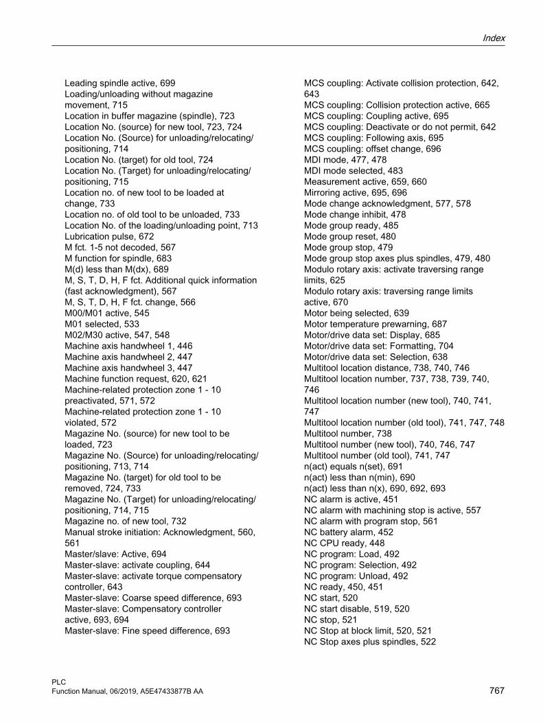
Leading spindle active, 699Loading/unloading without magazine movement, 715Location in buffer magazine (spindle), 723Location No. (source) for new tool, 723, 724Location No. (Source) for unloading/relocating/positioning, 714Location No. (target) for old tool, 724Location No. (Target) for unloading/relocating/positioning, 715Location no. of new tool to be loaded at change, 733Location no. of old tool to be unloaded, 733Location No. of the loading/unloading point, 713Lubrication pulse, 672M fct. 1-5 not decoded, 567M function for spindle, 683M(d) less than M(dx), 689M, S, T, D, H, F fct. Additional quick information (fast acknowledgment), 567M, S, T, D, H, F fct. change, 566M00/M01 active, 545M01 selected, 533M02/M30 active, 547, 548Machine axis handwheel 1, 446Machine axis handwheel 2, 447Machine axis handwheel 3, 447Machine function request, 620, 621Machine-related protection zone 1 - 10 preactivated, 571, 572Machine-related protection zone 1 - 10 violated, 572Magazine No. (source) for new tool to be loaded, 723Magazine No. (Source) for unloading/relocating/positioning, 713, 714Magazine No. (target) for old tool to be removed, 724, 733Magazine No. (Target) for unloading/relocating/positioning, 714, 715Magazine no. of new tool, 732Manual stroke initiation: Acknowledgment, 560, 561Master/slave: Active, 694Master-slave: activate coupling, 644Master-slave: activate torque compensatory controller, 643Master-slave: Coarse speed difference, 693Master-slave: Compensatory controller active, 693, 694Master-slave: Fine speed difference, 693
MCS coupling: Activate collision protection, 642, 643MCS coupling: Collision protection active, 665MCS coupling: Coupling active, 695MCS coupling: Deactivate or do not permit, 642MCS coupling: Following axis, 695MCS coupling: offset change, 696MDI mode, 477, 478MDI mode selected, 483Measurement active, 659, 660Mirroring active, 695, 696Mode change acknowledgment, 577, 578Mode change inhibit, 478Mode group ready, 485Mode group reset, 480Mode group stop, 479Mode group stop axes plus spindles, 479, 480Modulo rotary axis: activate traversing range limits, 625Modulo rotary axis: traversing range limits active, 670Motor being selected, 639Motor temperature prewarning, 687Motor/drive data set: Display, 685Motor/drive data set: Formatting, 704Motor/drive data set: Selection, 638Multitool location distance, 738, 740, 746Multitool location number, 737, 738, 739, 740, 746Multitool location number (new tool), 740, 741, 747Multitool location number (old tool), 741, 747, 748Multitool number, 738Multitool number (new tool), 740, 746, 747Multitool number (old tool), 741, 747n(act) equals n(set), 691n(act) less than n(min), 690n(act) less than n(x), 690, 692, 693NC alarm is active, 451NC alarm with machining stop is active, 557NC alarm with program stop, 561NC battery alarm, 452NC CPU ready, 448NC program: Load, 492NC program: Selection, 492NC program: Unload, 492NC ready, 450, 451NC start, 520NC start disable, 519, 520NC stop, 521NC Stop at block limit, 520, 521NC Stop axes plus spindles, 522
Index
PLCFunction Manual, 06/2019, A5E47433877B AA 767

NCU heat sink temperature alarm, 451NCU link: Active, 449NCU link: Axis active, 651NCU link: Axis ready, 655New tool: Internal T no. of the NC, 736New tool: Internal T number of the NC, 727, 744, 750New tool: Location type, 724, 725, 734, 741, 742New tool: Location type), 748New tool: Size bottom, 726, 735, 743New tool: Size left, 725, 734, 742New tool: Size left), 748New tool: Size right, 725, 734, 742New tool: Size right), 748, 749New tool: Size top, 725, 726, 735, 742, 743New tool: Size top), 749Online tool length compensation (TOFF) active, 576Online tool length compensation (TOFF): Compensation motion active, 576, 577Operating software ready, 450Orientation axis 1: Activate handwheel, 579, 580Orientation axis 1: active machine function, 589Orientation axis 1: handwheel active, 586, 587Orientation axis 1: invert handwheel direction of rotation, 584Orientation axis 1: machine function request, 583, 584Orientation axis 1: Rapid traverse override, 581Orientation axis 1: traversing command Plus / Minus, 588, 589Orientation axis 1: Traversing key lock, 580, 581Orientation axis 1: traversing keys plus / minus, 581, 582, 583Orientation axis 1: traversing request Plus / Minus, 587, 588Orientation axis 2: Activate handwheel, 584Orientation axis 2: active machine function, 590Orientation axis 2: handwheel active, 589Orientation axis 2: invert handwheel direction of rotation, 585Orientation axis 2: machine function request, 585Orientation axis 2: Rapid traverse override, 585Orientation axis 2: traversing command Plus / Minus, 590Orientation axis 2: Traversing key lock, 584Orientation axis 2: traversing keys plus / minus, 585Orientation axis 2: traversing request Plus / Minus, 590Orientation axis 3: Activate handwheel, 585Orientation axis 3: active machine function, 590
Orientation axis 3: handwheel active, 590Orientation axis 3: invert handwheel direction of rotation, 586Orientation axis 3: machine function request, 586Orientation axis 3: Rapid traverse override, 585Orientation axis 3: traversing command Plus / Minus, 590Orientation axis 3: Traversing key lock, 585Orientation axis 3: traversing keys plus / minus, 586Orientation axis 3: traversing request Plus / Minus, 590Original location of new tool, 728, 745, 751Original location of new tool in this turret magazine, 736, 737Original magazine of new tool, 727, 728, 744, 745, 751Oscillation active, 701, 702Oscillation cannot be started, 701Oscillation controlled by the PLC, 632, 633Oscillation enable, 633Oscillation reversal from external, 645Oscillation: Clockwise direction of rotation, 633, 634Oscillation: Counterclockwise direction of rotation, 634Overlaid motion, 698Override active, 608, 609Parameter set definitions disabled by NC, 623Path axis, 673Path feedrate override, 512, 513, 514Path feedrate override active, 519Path rapid traverse override, 514, 515, 516Path rapid traverse override active, 519PLC action completed, 507, 508PLC hardkeys, 492PLC index, 493PLC line offset, 493PLC-controlled axis, 649, 661PLC-controlled axis: Reset, 645, 646PLC-controlled axis: Resume, 646, 647PLC-controlled axis: Stop along braking ramp, 648PLC-controlled axis: Stop at the next reversal point, 648Position controller active, 657Position measuring system 1 activated, 702Position measuring system 1/2, 606, 607, 608Position measuring system 2 activated, 702, 703Position reached with exact stop coarse, 653Position reached with exact stop fine, 654Position restored, measuring system 1, 669
Index
PLC768 Function Manual, 06/2019, A5E47433877B AA

Position restored, measuring system 2, 669, 670Positioning axis, 673Power up completed, 688, 689Probe actuated, 449PROG_EVENT trigger event, 592, 593Program level abort, 518Program selection from the PLC: Active, 497, 498Program selection from the PLC: Error, 497Program selection from the PLC: Error code, 499, 500Program selection from the PLC: Index of the program list, 493, 494Program selection from the PLC: Job completed, 497Program selection from the PLC: Load, 498, 499Program selection from the PLC: Program index in the program list, 494, 495Program selection from the PLC: Selection, 499Program selection from the PLC: Unload, 498Program state aborted, 552, 553Program state interrupted, 552Program state running, 550Program state stopped, 551, 552Program state wait, 550, 551Program test (PRT) active, 549Program test (PRT) selected, 535, 536PTP traversing active, 575Pulse enable, 640Pulses enabled, 687Punch interface 1: Manual stroke initiation, 510, 511Punch interface 2: Manual stroke initiation, 512Ramp-function generator disable, 637, 638, 684Rapid traverse override, 619Read-in disable, 517Read-in disable is ignored, 559Recall alarms deleted, 495REF machine function, 481REF machine function active, 486, 487REF machine function selected, 484Reference point value 1-4, 613Referenced / synchronized 1, 652Referenced/synchronized 2, 653Referencing active, 546Remote diagnosis active, 447REPOS delay, 579, 623, 624REPOS delay acknowledgment, 668, 669REPOS delay active, 670REPOS machine function, 481REPOS machine function active, 486REPOS mode selected, 484REPOS offset, 667
REPOS offset valid, 668Request disabling of synchronized actions, 573Reset, 522, 523Reset executed, 661RESU: Backward/forward, 502RESU: Retrace mode active, 544RESU: Retrace support active, 544RESU: Start retrace support, 503Resynchronize spindle, measuring system 1, 630Resynchronize spindle, measuring system 2, 630, 631Resynchronizing the spindle during positioning, measuring system 1, 631Resynchronizing the spindle during positioning, measuring system 2, 631, 632Revolutional feedrate active, 546, 547, 659S function for spindle, 684SBH / SG deselection, 640SBH deselection, 640Screen is dark, 495SE selection, 641Second software limit switch minus, 625Second software limit switch plus, 625Selection: Coordinate system for Cartesian manual traversing and handwheel override in automatic mode in the tool direction (DRF), 597Selection: Position controller parameter set, 623Selects the file system, 493Sensor for fixed stop, 601Sensor S1 available (clamped state), 705Sensor S4 available (piston position), 705Sensor S4, piston end position, 708Sensor S5 available (angular position of the motor shaft), 705, 706Sensor S5, angular position of the motor shaft, 708Sensors available, 704, 705Set gear stage, 675Set reversal point, 647Setpoint limitation, 650Setpoint speed increased, 678Setpoint speed limited, 676, 677Setpoint switchover: drive control active, 694Setpoint switchover: request drive control, 643, 644SG selection, 640, 641Signal identifier for loading/unloading point, 713Simulation active, 496Simulation contour handwheel: Activation, 540, 541Simulation contour handwheel: Negative direction, 541
Index
PLCFunction Manual, 06/2019, A5E47433877B AA 769

Single block, type A, 482Single block, type B, 481, 482Skip block selected (SKP), 536, 537Software cams active, 658Software cams: Activation, 609Software cams: minus cam signal 1 to 32, 452, 453Software cams: plus cam signal 1 to 32, 453Sparking-out active, 701Speed controller active, 657, 658Speed controller integrator disable, 639Speed limit exceeded, 676Speed monitoring, 679Speed override, spindle-specific, 635, 636, 637Spindle, 650Spindle in position, 682, 683Spindle in setpoint range, 679SPL_READY, 487State of the clamping system, 706, 707Status axis/spindle replacement, 666Status of action 1 - 8, 596Status value is generated, speed limit p5043 is active, 706Stop at block end is ignored during single block (SBL), 560STOP_E, 487Stroke enable, 510Stroke initiation active, 560Stroke inoperative, 511, 512Stroke suppression, 511Suppress program test, 627, 703Switch over MCS/WCS, 496Synchronized action ID/IDS can be inhibited, 574Synchronous operation fine, 696, 697Synchronous operation, coarse, 697T function 1, 568T0, 730Tapping without compensating chuck active, 680Target number of workpieces reached, 574TEACH IN machine function, 480, 481TEACH IN machine function active, 486TEACH IN machine function selected, 483, 484Time monitoring active, 506Tool holder, 739, 744, 750, 751Tool management No., 712, 713, 721Tool management number, 731Tool status for new tool, 726, 727, 735, 736Tool status for new tool:, 743, 744, 749, 750Tool with dynamic response limitation, 682TOOLMAN: Deactivate wear monitoring, 539TOOLMAN: Deactivate workpiece counter, 538
TOOLMAN: Last replacement tool of the tool group, 592TOOLMAN: Tool limit value reached, 591TOOLMAN: Tool lock not active, 539TOOLMAN: Tool missing, 575TOOLMAN: Tool prewarning limit reached, 591TOOLMAN: Transition to new replacement tool, 591, 592Transformation active, 549Traversing command Plus / Minus, 664Traversing key lock, 618, 619Traversing key lock, geometry axis 2, 531Traversing keys plus / minus, 619, 620Traversing request Plus / Minus, 663, 664User-definable parameter 0 (DInt), 721, 722, 731User-definable parameter 1 (DInt), 722, 732User-definable parameter 2 (DInt), 722, 732Variable signaling function, 691Velocity alarm threshold reached, 698, 699Velocity/spindle speed limitation, 616
KKey disable, 113
MM decoding acc. to list, 83Machine control panel
M version, 308, 309Slimline version, 310, 311T version, 309, 310
MCP identification, 94MD14504, 87MD14506, 87MD14508, 87MD35400, 260MD51041, 110MD51043, 110MD9106, 110Memory requirements
of basic PLC program, 129Mode group, 74Multitool, 199
NNC
failure, 77-Read/write variables, 80
Index
PLC770 Function Manual, 06/2019, A5E47433877B AA

NC VAR selector, 133Alias name, 143Commissioning, installation, 148Compiling, 143Create a project, 138Create project list, 141Filtering the variable list, 139Open project, 138Save project, 138Software version, 139Transfer to STEP 7, 145
Number rangefor user program, 105
OOrganization block OB, 305
PPLC
Basic program functions, 31HMI monitor, 123Key disable, 113Program list, 109, 110-Versions, 31
PLC basic programAssignment overview, 105
PROFIBUSconnection, 96
PROFIBUS connection, 96PROFIBUS diagnostics, 76PROFINET
connection, 98Program
Select via PLC, 110
RREPOS activation, 543REPOS mode, 542, 543
SSignal exchange
Cyclic, 29Event-controlled, 29
SignalsCompile cycles, 57NCK/PLC, 58
PLC / mode group, 58, 59PLC/axes, spindles, 61PLC/NC, 57PLC/NCK channels, 59
Star-delta changeover, 254Startup and synchronization of NCK PLC, 73Symbolic programming, 81
TTimer No., 308
UUDT assignments, 82UTD-blocks, 81
Index
PLCFunction Manual, 06/2019, A5E47433877B AA 771

Index
PLC772 Function Manual, 06/2019, A5E47433877B AA