Embed Size (px)
Citation preview

FUMEOMILANO - ITALY
SUPER 6 TAV.
M0D. 9119/OM l
0
Supply arm *Arm lockerSupply pulleySpindle brakeLoop reformer leverFraming knobLamp-house screwArm locker .Take-up armTake-up .pulleySpindle brakeSpeed changeLamp-house cover.
12 Main switch13 Film drag lid14 Front elevation knob15 OPT/MAG switch16 Anamorphic lens17 Anamorphic holder34 Dampin c roller
r~ ^45 Projection lamp46 Lamp extractorFor model 9120 RECORD4748
49
bound on sound control,-*Frame counter (x 10)Reset push button
ttOV/MHi
*III
I-IWWT-! HtVI MONITOR AMn UCtT PWBMK »UX PhMAO UNI «C Iftn aLH. 1JA 1A 1AT
loQQOQO- OQQi
Cilogr.ll. F.<etn w

FUMEOMILANO - ITALY
SUPER 8
MOD. 9H9/OM
TAV.
2
35X36X37X38X39
4 • Loop reformer lever5 Framing knob
14 Front elevation..knob15 OPT/MAG switch16 Anamorphic lens17 Anamorphrc holder18 "Upper spocket.'shoe19 Damping roller'20 . Film guide roller21 • Upper sprocket22 Focussing knob •23 Pressure pad -24 . Lens holder25 Projection le-ns26 Sound pressure unit27 Loop reformer ,28 Projection gate pad29 ' Erase head (for record)
30 Magnetic head•31 Pressure unit drive32 Sound drum33 Lower sprocket
^34 Damping roller-35 Shoe roller36 Lower sprocket shoe37 Sound stabilizier
v
38 Sound unit connector39 Sound optic adjuster40 Exciter lamp cover41 Exciter lamp",42 Lamp connector43 Sound optic44 Sound optic focussingFor model 9120 RECORD47 Sound on sound control46 Frame counter (x 10}49 Reset push button
Etloflr.fi. F.ecin

INSTRUCTION MAlTim. to the use of theSuper 8 mm. projector model 9119/OM
1 Introduction.
la The Fumeo projector model 9H9/OM is a super 8 mm professional project-or for OPTICAL and MAGNETIC films, equipped with a 200 watt/24 voltsprojection lamp with dichroic reflector.It is a very rugged construction, while accuracy of work and selectionof components bring this projector to the same technological level ofthe best 16 mm. projectors.Its aims accept reels up to 750 »*• (2500') film, equivalent to about:2 hours and 30 minuts continuous projection.Film threading is manual and the projector can run in both forward andreverse direction.
lb The optical sound track is read directly on a sound drum equipped with' a flywheel of more than 1.2 Kgs; furthermore the sound optic is parti-cularly coated to give the highest performance also with sound tracksin colour.
Ic The projector is equipped with a professional amplifier having a power'output of undistorted 25 watt r.m.s.; its unique characteristic is thepresence filters adjustable in level, which acting in the range of thespeech frequencies helps to improve the intelligibility of the wordsin halls of poor acoustic.Bass frequencies can be increased or decreased +.10 dB at the referencefrequency of 100 Hz, while high frequencies can also be varied +_ 8 dBat the reference frequency of 10 KHz.
2 Preparation of the projector.
2a Place the projector on a stand or on a suitable table.2b Fold out arms 1_ and £ until they get locked; to close said arms back
push respectively buttons 2^ and "]_ while pressing the aiaa downwards.2c Turn,,if the case, knob 12 to position of STOP.2d By means of the cord supplied with the machine, connect the mains re-
ceptacle in the rear of the projector, to a suitable mains outlet ta-king care it corresponds to the operating voltage of the projector itself.
2e Turn knob 12 to FWD (forward) and the drive motor shall run.Move lever 10_ to make indication 24 appearing when projecting filmswhich must run at 24 frames per second, or indication 18 for films ma-de for. 16 or 18 fps.Said operation BftJST BE performed with the drive motor running.

2f Turn knob lj? tjo L.AMP to alight the projection lamp, then open lid 13.Make a first focussing of the projection gate by turning knob 22; ifthe projector is equipped with a zoom lens, remember that rotation ofits external ring produces a variation of the size of the projectedimage; afterwards a new focussing is required.For front elevation of the projector rotate knurled knob 14; rememberthe filament of the. lamp, when is incandescent, is very delicate andcan broken very easily; therefore when the lamp is alighted, position
the projector^ if: needed, in a gently way avoiding all rough movements.When all adjustment are made, turn knob 12 back to position STOP.
2g Move lever 15 towards "0" oir "M" according to the sound track of thefilm, being "0" for OPTICAL and "M" for MAGNETIC.Turn knob MODE of the amplifier to OPT when the sound track is opticaland the exciter lamp 41 will be switched on.For magnetic sound .track, knob MODE must be turned to MAG.
2h If required place an external speaker near the screen and connect itsplug to the socket marked SEKR on the rear of the projector. Said speak-er must have an impedance of 4 ohms and accept 25 watts.Still in the rear of the projector, the switch MONITOR drives an inter-nal speaker through 3 positions: Normal, Low, Off.
3 Film threading.
3a Turn open lid 13; inside there is reported the threading diagram.3b Push downwards sprocket shoes 18 and 36; swinj, open lens holder _2 .3c Place the reel of the film on arm Ij unroll about 1 metre of film and
proceed to threading according to the diagram.Take care that film perforation enters the teeth of the sprocket befo-re pushing back the relative shoe and that pad 23 be correctly posi-tioned.The pressure roller of unit 26^ is automatically lifted up -when knob 12is on position of STOP, or on REV, or on REV/LAMP.
3d Tie the leader of the film to an empty reel placed on take-up arm 8.Note that in FORWARD operation, said reel rotates in the clockwisedirection.
3e Take care that metallic belts be well placed around the pulleys oftheir relative arms.
To manually check for proper threading, rotate the motor knob.locatedbeside arm _8.
4 Projection.
4a Turn knob l£ to FWD taking care the film runs properly and then to LAMP.
4b Focus the image by means of knob 22; if necessary readjust the size ofthe image by turning the external ring of the zoom lens, if the project-or is equipped wi'th said type of lens; thereafter a new operation offocussing has to be made.

4c Rotation of knob in one sense or in the other, will properly posi-tion the film frameline respect to the projection gate. No displace-ment of the illuminated area on the screen will however ocoiir duringframing operation. .. ,.
4d Damaged perforation or poor splices may cause excessive reduction ofthe lower loop; this trouble produces a high instability of the pic-ture on the screen and loud chattering.Rapidly push then lever 4. which acting on roller 27 will restore thelower loop.
4e Adjust control LEVEL to have a suitable volume of sound and controlsBASS, TREBLE, FILTER to obtain the best quality of the sound.
4f When the projection is ended turn knob 12 back to STOP.
4g Projection of.film with optical or magnetic sound track:
optical sound: ,- push lever 13 towards letter "0" (optical)- push lever 10 outwards to have indication 24- turn knob MODE of the amplifier to OPT
magnetic sound:- push lever Ijj) towards sign '$!" (magnetic)- push lever 10 outwards to have indication 24 for film recorded at that. speed, or inwards to have sign 18 in the other case. Remember that the
speed of 18 fps is usually used for silent film and anyhow the rangeof the reproduced frequencies is reduced.
- turn knob MODE of the amplifier to MAG (magnetic)
5 Rewinding.
5a Rewinding is performed without removing the reels. Just tie the end ofthe film to the core of the reel on the supply arm, then turn knob 12to REVerse.Remember the supply reel will turn now in counter-clockwise direction.If the case, the disc of the friction can be tighten a bit more inorder to have better film rewinding.
5b Rewinding can be performed even if a certain quantity of film is stillleft on the reel: remove the film from the machine and proceed as ex-plained above. It is not advisable to operate in REVerse with the filmthreaded on the projector, since it will run at 18 or 24 fps and thusit will take too long.
6 Amplifier.
6a The projector is equipped with a high level professional amplifier whichdelivers a power output of 25 watt nas over 4 ohm load.

FUMEO.p. A.
4
6 b The amplifier is equipped with the following controls:
MORE rotary switch to select inputs:— MIC low impedance microphone- AUX auxiliary input of medium sensitivity -• ••- PhM phono magnetic- OPT film with optical sound track (lever 15 to "0")- MAG film with magnetic sound track (lever 15 to "M")- EEC magnetic recording for projectors equipped accordinglyLEVEL controls the level of signal selected through MODEFILTER increases a band of frequencies centred around 2 KHz in
order to improve the intelligibility of the speech inhalls of poor acoustic or with low quality sound film
TREBLE controls the high frequencies giving +_ 8 dB at 10 KHzBASS controls the low frequencies giving £ 10 dB at 100 HzOn the rear of the projector it is located the following:
inputslow impedance microphone 0.2 mVolt/600 ohmsauxiliary input 63 mVolt/100 Kohms
phono magnetic 1*3 mVolt/68 Khomsconnection to an external mixer for recording operation
6 c
77 a
7 b
7 c
7 d
- MIC- AUX- PhM- EECoutputs-.LIKE- SPKR
0.5 Volt/47 Kohmsconnection to an external speaker 4 ohm/25 watts
- MONITOR 3 position switch to drive the internal speaker at 3 differ-ent levels: N normal 2.5 watts; L low 0.75 watts; 0 off.
fuses- AKPL 1.5 amps for the amplifier only- EXCT 2 ampB for the exciter lamp power supply- POWER 2 AT for the mains 220 volts.
*
Anamorphio lens.
The anamorphic lens is a special lens which, while keeping the heightof the projected image at the same dimension, increases 2 times thewidth of said image; it is used for film in CIRIMASCOPE.Introduce the anamorphic lens holder 17 in the guides of the relativebracket, then focus image of the film using knob 22.Introduce the anamorphic lens 16 in the holder, as inside as pgssible.Turn the whole anamorphic lens to give on the screen a perfect retanglewhose base is horizontal, then tighten the lens to the holder by meansof the relative thumb screw.Make a fine focussing of the image, acting this time on the externalring of the anamorphic lens.

8 Reel friction and brake.
8a Adjustable frictions are assembled on pulleys _^ and £ to have a correctfilm drag with no slackening, as function of the size of the reels. Keepthe spindle firm with one hand, with the other hand screw or unscrew thelarge knurled nut. Remember if friction is too tighten, the dragging eff-ect on the film might damage the film perforation.
8b In orader to have the reel not too loosen, a braking effect can be appli-ed on spindles by means of thumbscrews 3a and 9a. Said effect must be ad-justed to a minimum to avoid excess of work of the frictions. The moresaid thumbscrews are tighten, the more spindles are braked, the more fric-tions have to be tighten as well.
9 Fuse replacement.
9a DISCOMECT the projector fi om mains any time a fuse has to be replaced.Unscrew cover of fuse receptacle and replace blown fuse with one havingthe same rating value. NEVER put a fuse with different characteristicssince the projector might suffer more damages.
9b If a fuse just replaced blows again, it is strongly recommended to take .the projector to a technician for proper assistance.
10 Exciter lamp replacement.
lOa Pull off' lamp cover 40 and remove lamp 41 which is glued to its socket.lOb Replace the lamp; run the projector with an optical film and find the
best position of the lamp for the highest sound output, then put againsome cement to keep the lamp in the correct position.
WARNING: do not move or touch the sound optic, since for its alignmenttest film and suitable instrumentation are needed.
11 Projection lamp replacement*
lla Remove thumb screw 6_ and swing open lamp-house cover 11 together withlid 1 .
lib Pulling up the small lever 46 below the lamp socket remove the projec-.tion lamp 45. <..
.- •*lie Replace the lamp taking care the new one enters correctly in its place.
Ho further alignment is required since these lamps are prefocussed.
12 Lubrication.
12a Open lamp-house cover 11; put few drops of oil on the felt located justover the shutter, after about each 40-50 hours projection. Careful notto drop oil on the belts. The remaining components are life-lubricatedand do not need any intervention; in case of periodical inspection how-ever, few drops of oil can be put on all shafts and gears.
FUMEOm.p.A.
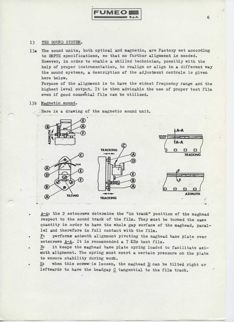
13 THE SOITO SYSTEM.
13a The sound units, "both optical and magnetic, are Factory set accordingto SMPTE specifications, so that no further alignment .is needed.However, in order to enable a skilled technician, possibly with thehelp of proper instrumentation,, to realign or align in a different waythe oound systems, a description of the adjustment controls is givenhere below.Purpose of the alignment is to have the widest frequency range and thehighest level output. It is then advisable the use of proper test filmeven if good comme'cial film can be utilized.
13b Magnetic sound.
Here is a drawing of the magnetic sound unit.
SOUNDTRACK
9TRACKING /
TILTING
1 — d/ 1
A- A
!—*- -J L
A-A
3 D D1
o (TRACKING
AZIMUTHTRACKING
A-A: the 2 setscrews detennine the "in track" position of the magheadrespect to the sound track of the film. They must be turned the samequantity in order to have the whole gap surface of the maghead, paral-lel and therefore in full contact with the film..F: performs azimuth alignment pivoting the maghead base plate oversetscrews A—A. It is recommended a 7 KHz test film.13: it keeps the maghead base plate spring loaded to facilitate azi-muth alignment. The spring must exert a certain pressure on the plateto ensure stability during work.
Ei when this screwris loosen, the maghead I) can be tilted right or
leftwards to have the headgap £ tangential to the film track.

FUMEOB.p.A.
13c Optical sound.
Two alignments can "be made: one concerns the sound optic C_ and the otherone the exciter lamp M which is 6 volt/10 watts.
lOUNDfc!!!!«;.:_! !l.y.!i;nttx..' '
D P D ITRACKING
AZIMUTH
Sound optic.
Turning of screw A determines the "in track" position of the readinglight "beam respect to the sound track of the film.Azimuth of the reading beam can be adjusted by turning (just a smallangle) one or the other direction the sound optic £; loosen first thelocking screw IJ. It is recommended a 5 KHz or 7 KHz test film.Focussing the sound optic on film is performed by turning screw L
which is tighten with its nut. The whole unit is pivoted on screw A
and kept spring loaded by spring N. Use 5 KHz or ?KHz film.
Exciter lamp.
The lamp is factory glued to its socket. After replacement, thread a
good film and move the lamp with, fingers until the highest level out-
put is obtained; put few drops of any cement to keep the lamp in thecorrect position.
(J: the whole lamp "base pivots on pin £ and aligns the filament re-spect to the horizontal axis of the sound optic.

FUMEO6
E-E; loosen these screws just enough to allow the lamp base plate to
turn on itself in order to put the filament parallel to the plane pfthe sound optic lens.
D-D; these two screws move up or down the lamp in order' to place thefilament just in firont of the slit of the sound optic.][; it tilts the lamp filament respect to the slit of the sound op-tic.H: it keeps the lamp "base plate spring loaded to ensure stabilityduring operation.
Note; all adjustments have to be repeated several times one after theother since they are interdependents.

Technical specifications.
Mod 9119/OM, super 8 mm projector for replay only of OPTICAL and MAG-39STIC sound track films. It operates at 220 volt/50 cps.Speed: 18 and 24 fps with maintenance free asynchronous motor.Spools: accepts up to 750 mt (2500 ft) spools, " "Threading: all manual.Film transport: two-tooth hardened claw, with two sprockets of highaccuracy; manual film loop reformer; framing performed "by claw di-splacement so that no further tilting correction is needed.Operation: performed by one control only for: STOP, FORWRD and LAMP,REVERSE and LAMP.Projection lamp: 24 volt/200 watts EJL or similar.Projection lens: zoom 16.5 ~ 30 mm; other focalities on request.Anamorphic lens: 2 threaded holes provided; anamorphic holder and lenssupplied on request.
iElectronic characteristics:* amplifier fully transistorized with discrete replaceable components,
output 25 "watts r.m.s. undistorted over a load of 4 ohms.. inputs for microphone, pick-up magnetic, auxiliary, record (for mo-
dels where recording capability is provided), switch to select thedifferent mode inputs.
. controls for IEVEL, PRESENCE, TREBIE, BASS.
.' two outputs: loudspeaker 4 ohm/25 watts; line 0.5 Volt/4? Kohms.
. internal speaker 8 ohm/6 watts, with 3 position switch: Hormal, Low, Off
. fuses for mains, exciter lamp, amplifier.
. optical sound replay: 40 Hz - 6500 Hz (at 24 fps), with sound opticspecially coated for sound track in colour also.
. magnetic replay: 40 Hz - 12000 Hz at 24 fps.
Weight without spools: 14.2 Kg.Dimensions with the arms folded: 44 * 34 i 22 cm.
Pumeo spa reserves all rights of modification without previous notice.

.;_ j
A1Y1I - ONV1IW
oawnj


00
cr
0-
Oicfl
T
3 UJ
a-;
00
o
0000
o~
H
_ii
9ff^
IA3« i ^
J^olUPl SoO 52+—m
i-'ito ^4.gss^T T


1 °"f—SzfKLOW O~UV
t 1 J 1(1
FUMEO S.P.A.
Denominazione:

X
x
FUMEO S. p. A. - FABBRICA APPARECCHIATURE CINEMATOGRAFICHE - MILANO
Denominazione: