Embed Size (px)
Citation preview

Fully Autonomous Operations of a Jacobs Rugbotin the RoboCup Rescue Robot League 2006
Kaustubh Pathak, Andreas Birk, Soren Schwertfeger, Ivan Delchev, and Stefan MarkovSchool of Engineering and Science
Electrical Engineering and Computer Science (EECS)Jacobs University Bremen
Campus Ring 1, D-28759 Bremen, [email protected], http://robotics.jacobs-university.de
Abstract — This paper describes the latest version of an integratedhardware and software framework developed for autonomous oper-ation of rescue robots. The successful operation of an autonomousrugbot - short for ”rugged robot - was especially demonstrated duringseveral runs at the RoboCup world championship 2006 in Bremen.The design of the autonomous system is described in detail with anemphasis on extendibility and the specific requirements of a typicalunstructured rescue scenario.
Keywords: Autonomous System; Safety, Security, and Res-cue Robotics (SSRR); Behavior-Oriented Control; Navigation;Exploration
I. INTRODUCTION
Existing professional rescue robots are optimized withrespect to locomotion and ruggedness. They are proven tobe useful, field-able devices [1][2][3][4][5][6], but they havetheir limitations. Especially, they require teleoperation by auser. Due to the high cognitive demands on the operator inpurely teleoperated mode [7], any bit of intelligence addedmakes the systems more useful. There are additional reasonsto strive for intelligent functionalities up to full autonomy onthe robots. First of all, there are technological aspects like thelimitations of communication systems. Second, there are thelogistic aspects of rescue operations. Human rescue workersare a scarce resource at accident sites. A single operator shouldhence supervise as many robots working in parallel as possible.A more detailed discussion of the scopes of autonomy forrescue robotics can be found in [8].
Fig. 1. The RoboCup rescue competition features a very complex testenvironment (left), which includes several standardized test elements. TheJacobs team demonstrated at the world championship 2006 a combined usageof a teleoperated with a fully autonomous robot (right).
The framework for autonomous operation of a rescue robotpresented here is an extension of an earlier system [9]. Thenew framework has been successfully run in the Robocup2006 competition, where the Jacobs team made it as theonly participant with intelligent functionalities on board ofthe robots into the final round. Fig. 2 shows a screenshot ofthe GUI used by the operator to view robot’s progress andinteract with it on victim detection. Fig. 2 shows a mapautonomously generated by the robot during one of the runsat Robocup rescue league. The identified victims are indicatedby their numbered IDs on the map. The RoboCup RescueLeague in general offers an interesting option to explore theprospects of intelligent rescue systems, as also indicated byrelated work, e.g., on navigation and exploration for rescue[10] or autonomous victim detection [11].
Fig. 2. A screen-shot of the GUI running on an operator station (left). Amap completely autonomously created during an actual run at Robocup 2006(right). The numbers on the map are the victim IDs.
II. HARDWARE DESCRIPTION
The Rugbot rescue robot platform is a complete in-housedevelopment based on the so-called CubeSystem, a collectionof hardware and software components for fast robot proto-typing [12]. Rugbots are tracked vehicles that are lightweight(about 35 kg) and have a small footprint (approximately 50cm x 50 cm). They are very agile and fast on open terrain. Anactive flipper mechanism allows Rugbots to negotiate stairsand rubble piles. Some additional information on the robotas well as its teleoperation software can be found in [13]. Amore detailed description of the locomotion mechatronics ofthe robot is given in [14].

Fig. 3. An autonomously detected victim. The top image shows an overviewphoto taken by a spectator of the robot after it detected a victim - the armin the box. The bottom images are the robot’s view of a different detectedvictim. The left image is from the webcam on the robot, and the right imageis from the thermocam on the robot.
Thermocam�
Front LRF�
Inclined LRF�
Swissranger�
Webcam�
Fig. 4. The autonomous rescue robot Rugbot with some important onboardsensors pointed out.
The robot’s onboard sensors can be categorized as follows:1) Odometry Information
a) The CubeSystem has the provision of returningOdometry data using Serial communication.
b) XSense MTi Gyros for providing the robot headingdirection or yaw, pitch, and roll. This yaw is usedto correct and recalibrate the drift in the odometryreturned by the CubeSystem.
2) Camerasa) A Panasonic KX-HCM280 pan-tilt webcam with
optical zoom.b) A Philips USB Cam for front view. Optionally, a
back camera, and side view cameras of the twotracks can be installed.
3) 2D Range Detectiona) Two Hokuyo URG-04LX Laser Range Finders
(LRF): One for frontal obstacles (LRFF) and an-other inclined (LRFD) for detecting immediate
movement impediments like ditches, and blocks.These range finders have a field of view (FOV) of240
o comprising of about 680 beams.4) 3D Range Detection
a) a stereo-camera model STH-DCSG-STOC-C fromVideredesign for 3D frontal obstacle range detec-tion.
b) a Swiss-ranger SR-3000 from CSEM for 3D frontalobstacle range detection.
5) Other sensorsa) a FLIR thermocamera for temperature information
in a range of �40
oC to 120
oC with 0.08
oC reso-lution.
b) a CO2 detector
III. SOFTWARE FRAMEWORK
The software framework is coded in C++, and consists oftwo main modules: a server program running on the robotonboard computer, and a graphical user interface running onan operator station. The communication between these twomodules is handled using the Neutral Messaging Language(NML) memory buffers of the NIST RCS library [15]. Thisis shown in Fig. 5.
NML Buffers
Robot
Robot PC
<<process>>Robot Server
<<process>>NML Server
Operator PC
<<process>>GUI
Cube System<<process>>Cube Program
NML Local Communication
NML TCP/IP
Serial Communication
Buffers
Threads
Threads
Fig. 5. UML Deployment diagram showing the overall system.
A. NML Server
This server is spawned by the robot server on initialization.Thereafter, it takes care of buffering messages between therobot-server and its clients. Messages arriving in a bufferoverwrite previous messages. Currently, the framework has tenbuffers. The most important being: the actuation commandsbuffer for sending operator joystick speed and flipper com-mands to the robot server, and other buffers for receiving thesamples of various sensors, and results of mapping algorithms.

B. The Multi-threaded Robot ServerThe server program is multi-threaded and runs on the SUSE
Linux O/S. There are separate threads to handle the followingtasks.
1) One thread each for all the onboard sensors and actua-tors, viz. Gyro, Cube serial communication, LRF (frontand inclined), CO2 sensor, stereo-camera, swiss-ranger.
2) The image capturing of the themo-cam and variouswebcams is done by a palantir server [16].
3) One main thread for sensor data collection and NMLcommunication with the client. The latter includes send-ing actuator and speed commands to the Cube thread.
4) One thread each for all the mapping threads. Currentlywe have a basic occupancy grid based mapping, aSLAM algorithm based on scan-matching [17], and a3D occupancy grid based algorithm.
5) Autonomy thread for autonomous operation of the mo-bile robot. This thread analyzes sensor data and gener-ates actuator and speed commands which are sent to theCube thread via the main thread. The autonomy threadcan be started and stopped from the remote operatorGUI. This allows the operator to take charge in difficultsituations, and drive the robot using a joystick. Theautonomy thread in turn spawns auxiliary threads forautomatic victim detection. Currently we have imple-mented the following algorithms.
a) A thread which detects motion in the webcamimage when the robot is stationary.
b) A thread which scans the thermocam images forwarm or heated objects.
Fig. 6. UML class diagram showing the principal threads involved in theautonomous mode. Mapping and camera threads are not shown for clarity.
As shown in Fig.6, all thread classes derive from a genericthread class. All sensor-thread classes are derived from atemplated SensorThread class which takes care of mutexlocking and data copying. Similarly, all mapping-thread classesare derived from a generic MappingThread class frameworkwhich takes care of distributing odometry and LRF sensordata to all mappers and transmission of the resulting map tothe NML buffer, from where the operator GUI can fetch it.
TABLE IPARAMETER LIST
VRot 1250 mm/sVFwd 1750 mm/s�T
S
0.5 sNBeams 682hLRFD 400 mmfR
min 0
fR
max 3/8fF
min 3/8
fF
max 5/8fL
min 5/8
fL
max 1dF
min 280 mmdF
max 600 mmdF
IgnoreSide 600 mm
dF
SD 310 mmdF
SHD 600 mmdF
SideMax 700 mm� 0.693/(dF
SHD � dF
SD)
C. The Autonomy Thread Main Loop
Remark 3.1 (Basic Idea): A behavior is a complex se-quence of motions executed by the robot in response to asituation detected through its sensors. Behaviors can be aggre-gated together to form a new behavior. We distinguish betweena behavior and a primitive motion like in-place rotation orpure translation. There is always an active (current) behaviorwhich handles the situation, i.e., computes motion and actuatorcommands for the robot.
A new behavior is selected at each time instant basedon the robot’s perception. If a behavior has not finished itscomplete sequence of motions, it can ask the autonomy threadto consider running it in the next sample instant. This is,however, not guaranteed. This mechanism allows all behaviorsto be interrupted in mid-run if a situation with a higher severityoccurs which can best be handled by another behavior.
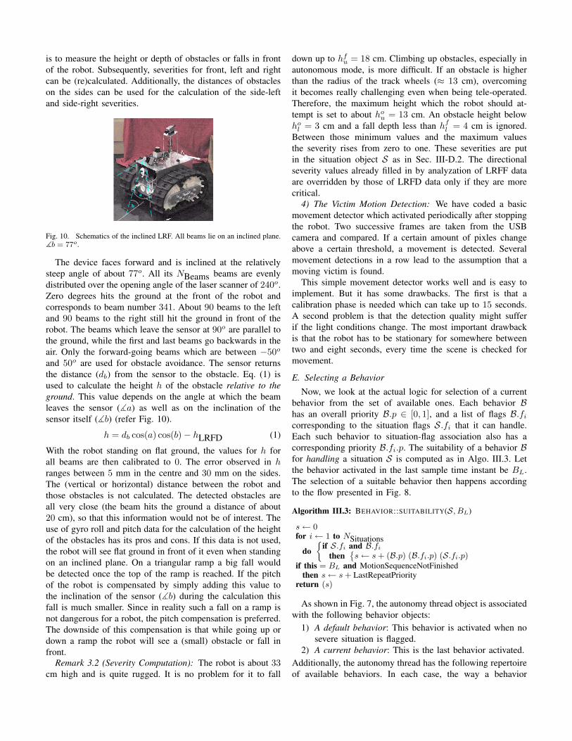
Fig. 8 shows an overview of one step of the autonomy thread(shown as an object of AutonomousMode class) main loopusing a UML collaboration diagram. The static relationshipsbetween participating classes is shown in Fig. 9. At eachsample time instant within this loop, all the sensors threads aresampled and their data analyzed to fill in a current situationobject. The design of the Situation class is depicted inFig. 9. A Situation object S has boolean flags S.f
i
, i =
1 . . . NSituations, for flagging various runtime conditions likenearby obstacles, dangerous pitch or roll, whether the robotis stuck or near a fall, whether any of the automatic victimdetection algorithms found a victim, etc. Each such flag S.f
i
has its own statically assigned priority S.fi
.p. Each flag is as-sociated with an overall runtime severity value S.f
i
.s 2 [0, 1].Furthermore, this severity value is also provided directionally,e.g. if an obstacle is flagged, one can check all the differentdirections in which an obstacle has been detected, and what therelative severities S.f
i
.s[Direction] 2 [0, 1] are. How situationsare analyzed and how severity values are arrived at will be
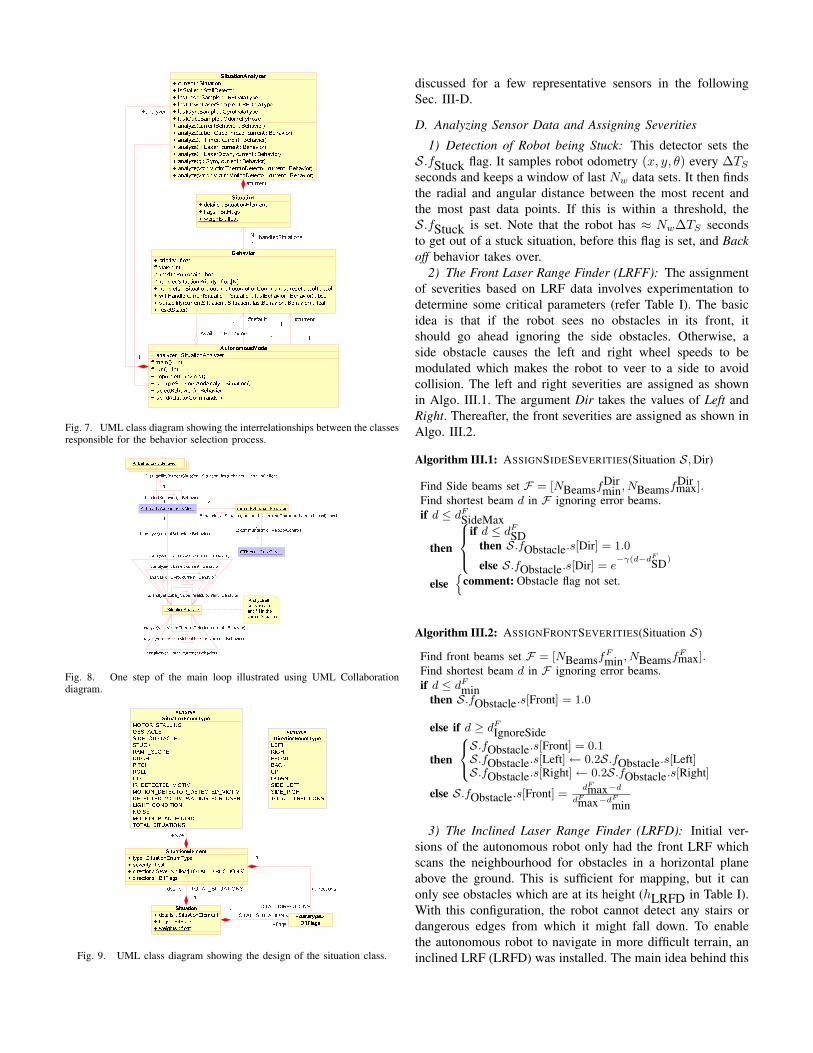
Fig. 7. UML class diagram showing the interrelationships between the classesresponsible for the behavior selection process.
Fig. 8. One step of the main loop illustrated using UML Collaborationdiagram.
Fig. 9. UML class diagram showing the design of the situation class.
discussed for a few representative sensors in the followingSec. III-D.
D. Analyzing Sensor Data and Assigning Severities
1) Detection of Robot being Stuck: This detector sets theS.fStuck flag. It samples robot odometry (x, y, ✓) every �T
S
seconds and keeps a window of last Nw
data sets. It then findsthe radial and angular distance between the most recent andthe most past data points. If this is within a threshold, theS.fStuck is set. Note that the robot has ⇡ N
w
�TS
secondsto get out of a stuck situation, before this flag is set, and Backoff behavior takes over.
2) The Front Laser Range Finder (LRFF): The assignmentof severities based on LRF data involves experimentation todetermine some critical parameters (refer Table I). The basicidea is that if the robot sees no obstacles in its front, itshould go ahead ignoring the side obstacles. Otherwise, aside obstacle causes the left and right wheel speeds to bemodulated which makes the robot to veer to a side to avoidcollision. The left and right severities are assigned as shownin Algo. III.1. The argument Dir takes the values of Left andRight. Thereafter, the front severities are assigned as shown inAlgo. III.2.
Algorithm III.1: ASSIGNSIDESEVERITIES(Situation S, Dir)
Find Side beams set F = [NBeamsfDirmin, NBeamsf
Dirmax].Find shortest beam d in F ignoring error beams.if d dF
SideMax
then
8><
>:
if d dF
SDthen S.fObstacle.s[Dir] = 1.0
else S.fObstacle.s[Dir] = e��(d�d
F
SD)
else
ncomment: Obstacle flag not set.
Algorithm III.2: ASSIGNFRONTSEVERITIES(Situation S)
Find front beams set F = [NBeamsfF
min, NBeamsfFmax].
Find shortest beam d in F ignoring error beams.if d dF
minthen S.fObstacle.s[Front] = 1.0
else if d � dF
IgnoreSide
then
8<
:
S.fObstacle.s[Front] = 0.1S.fObstacle.s[Left] 0.2S.fObstacle.s[Left]S.fObstacle.s[Right] 0.2S.fObstacle.s[Right]
else S.fObstacle.s[Front] =d
Fmax�d
d
Fmax�d
F
min
3) The Inclined Laser Range Finder (LRFD): Initial ver-sions of the autonomous robot only had the front LRF whichscans the neighbourhood for obstacles in a horizontal planeabove the ground. This is sufficient for mapping, but it canonly see obstacles which are at its height (hLRFD in Table I).With this configuration, the robot cannot detect any stairs ordangerous edges from which it might fall down. To enablethe autonomous robot to navigate in more difficult terrain, aninclined LRF (LRFD) was installed. The main idea behind this
is to measure the height or depth of obstacles or falls in frontof the robot. Subsequently, severities for front, left and rightcan be (re)calculated. Additionally, the distances of obstacleson the sides can be used for the calculation of the side-leftand side-right severities.
b�
a�
Fig. 10. Schematics of the inclined LRF. All beams lie on an inclined plane.]b = 77o.
The device faces forward and is inclined at the relativelysteep angle of about 77
o. All its NBeams beams are evenlydistributed over the opening angle of the laser scanner of 240
o.Zero degrees hits the ground at the front of the robot andcorresponds to beam number 341. About 90 beams to the leftand 90 beams to the right still hit the ground in front of therobot. The beams which leave the sensor at 90
o are parallel tothe ground, while the first and last beams go backwards in theair. Only the forward-going beams which are between �50
o
and 50
o are used for obstacle avoidance. The sensor returnsthe distance (d
b
) from the sensor to the obstacle. Eq. (1) isused to calculate the height h of the obstacle relative to theground. This value depends on the angle at which the beamleaves the sensor (]a) as well as on the inclination of thesensor itself (]b) (refer Fig. 10).
h = db
cos(a) cos(b)� hLRFD (1)
With the robot standing on flat ground, the values for h forall beams are then calibrated to 0. The error observed in hranges between 5 mm in the centre and 30 mm on the sides.The (vertical or horizontal) distance between the robot andthose obstacles is not calculated. The detected obstacles areall very close (the beam hits the ground a distance of about20 cm), so that this information would not be of interest. Theuse of gyro roll and pitch data for the calculation of the heightof the obstacles has its pros and cons. If this data is not used,the robot will see flat ground in front of it even when standingon an inclined plane. On a triangular ramp a big fall wouldbe detected once the top of the ramp is reached. If the pitchof the robot is compensated by simply adding this value tothe inclination of the sensor (]b) during the calculation thisfall is much smaller. Since in reality such a fall on a ramp isnot dangerous for a robot, the pitch compensation is preferred.The downside of this compensation is that while going up ordown a ramp the robot will see a (small) obstacle or fall infront.
Remark 3.2 (Severity Computation): The robot is about 33
cm high and is quite rugged. It is no problem for it to fall
down up to hf
u
= 18 cm. Climbing up obstacles, especially inautonomous mode, is more difficult. If an obstacle is higherthan the radius of the track wheels (⇡ 13 cm), overcomingit becomes really challenging even when being tele-operated.Therefore, the maximum height which the robot should at-tempt is set to about ho
u
= 13 cm. An obstacle height belowho
l
= 3 cm and a fall depth less than hf
l
= 4 cm is ignored.Between those minimum values and the maximum valuesthe severity rises from zero to one. These severities are putin the situation object S as in Sec. III-D.2. The directionalseverity values already filled in by analyzation of LRFF dataare overridden by those of LRFD data only if they are morecritical.
4) The Victim Motion Detection: We have coded a basicmovement detector which activated periodically after stoppingthe robot. Two successive frames are taken from the USBcamera and compared. If a certain amount of pixles changeabove a certain threshold, a movement is detected. Severalmovement detections in a row lead to the assumption that amoving victim is found.
This simple movement detector works well and is easy toimplement. But it has some drawbacks. The first is that acalibration phase is needed which can take up to 15 seconds.A second problem is that the detection quality might sufferif the light conditions change. The most important drawbackis that the robot has to be stationary for somewhere betweentwo and eight seconds, every time the scene is checked formovement.
E. Selecting a Behavior
Now, we look at the actual logic for selection of a currentbehavior from the set of available ones. Each behavior Bhas an overall priority B.p 2 [0, 1], and a list of flags B.f
i
corresponding to the situation flags S.fi
that it can handle.Each such behavior to situation-flag association also has acorresponding priority B.f
i
.p. The suitability of a behavior Bfor handling a situation S is computed as in Algo. III.3. Letthe behavior activated in the last sample time instant be B
L
.The selection of a suitable behavior then happens accordingto the flow presented in Fig. 8.
Algorithm III.3: BEHAVIOR::SUITABILITY(S, BL
)
s 0for i 1 to NSituations
do
⇢if S.f
i
and B.fi
then
�s s + (B.p) (B.f
i
.p) (S.fi
.p)if this = B
L
and MotionSequenceNotFinishedthen s s + LastRepeatPriority
return (s)
As shown in Fig. 7, the autonomy thread object is associatedwith the following behavior objects:
1) A default behavior: This behavior is activated when nosevere situation is flagged.
2) A current behavior: This is the last behavior activated.Additionally, the autonomy thread has the following repertoireof available behaviors. In each case, the way a behavior
handles a situation, i.e., computes motion commands is alsodescribed in brief. The motion commands ususally consist ofthe left and right wheel speed (v
L
, vR
) in mm/s, though, theycould also activate auxilliary actuators like the flipper. Referto Table I for parameter definitions.
1) Obstacle Avoidance: This is the default behavior whichhandles the flag S.fObstacle. It is a stateless purelyreactionary behavior and as such does not requireto be run again to complete its sequence. Therefore,variable MotionSequenceNotFinished mentioned inAlgo. III.3 is always false.
vL
VFwd�1� S.fObstacle.s[Forward]
�,
vL
vL
� VRotS.fObstacle.s[Right]. (2)v
R
VFwd�1� S.fObstacle.s[Forward]
�,
vR
vR
� VRotS.fObstacle.s[Left]. (3)
2) Largest Opening: This behavior does not handle anysituational flags directly, but is aggregated within otherbehaviors, e.g. Back off. It makes use of the LRFF datato find the largest opening amongst obstacles for therobot to escape, and rotates the robot to that direction.As noted in Remark 3.1, this behavior can be interruptedbefore reaching its end.
3) Back off: It handles situational flags S.fStuck, S.fDitch,S.fRoll/Pitch, S.fMotorsStalling. Essentially, it backsup a certain distance and then calls Largest Opening.As noted in Remark 3.1, this behavior can be interruptedbefore reaching its end.
4) Victim Found: It handles the following situational flags:
S . fIRDetectedVictim,
S . fMotionDetectorDetectedVictim,
S . fDetectedVictimWaitingForUser.
This behavior has the highest priority, and cannot beinterrupted by another behavior. It basically stops therobot and waits till a user confirmation is received or atimer times out.
5) Motion Planner: This behavior is run periodically basedon a situational flag set by a timer. It samples the motionplanner thread which tries to find paths to unexploredregions based on the generated occupancy grid map.The behavior runs only when no critical situations areflagged. It rotates the robot in the direction of theplanned path.
IV. CONCLUSIONS
This paper presented an integrated hardware and softwareframework for autonomy of a rescue robot. This frameworkwas field tested in Robocup 2006.
ACKNOWLEDGMENTS
The authors gratefully acknowledge the financial support ofDeutsche Forschungsgemeinschaft (DFG).
Please note the name-change of our institution. The SwissJacobs Foundation invests 200 Million Euro in International
University Bremen (IUB) over a five-year period startingfrom 2007. To date this is the largest donation ever given
in Europe by a private foundation to a science institution.In appreciation of the benefactors and to further promote theuniversity’s unique profile in higher education and research,the boards of IUB have decided to change the university’sname to Jacobs University Bremen. Hence the two differentnames and abbreviations for the same institution may befound in this article, especially in the references to previouslypublished material.
REFERENCES
[1] T. Kamegawa, T. Yamasaki, and F. Matsuno, “Evaluation of snake-like rescue robot ”kohga” for usability of remote control,” in IEEEInternational Workshop on Safety, Security and Rescue Robotics, SSRR,2005, pp. 25–30.
[2] S. Kang, W. Lee, M. Kim, and K. Shin, “Robhaz-rescue: rough-terrainnegotiable teleoperated mobile robot for rescue mission,” in IEEEInternational Workshop on Safety, Security and Rescue Robotics, SSRR,2005, pp. 105–110.
[3] A. Davids, “Urban search and rescue robots: from tragedy to technol-ogy,” Intelligent Systems, IEEE, vol. 17, no. 2, pp. 81–83, 2002.
[4] R. G. Snyder, “Robots assist in search and rescue efforts at wtc,” IEEERobotics and Automation Magazine, vol. 8, no. 4, pp. 26–28, 2001.
[5] R. R. Murphy, J. Casper, and M. Micire, “Potential tasks and researchissues for mobile robots in robocup rescue,” in RoboCup-2000: RobotSoccer World Cup IV, ser. Lecture notes in Artificial Intelligence (LNAI),P. Stone, T. Balch, and G. Kraetszchmar, Eds. Springer Verlag, 2001,vol. 2019, pp. 339–334.
[6] J. Abouaf, “Trial by fire: teleoperated robot targets chernobyl,” ComputerGraphics and Applications, IEEE, vol. 18, no. 4, pp. 10–14, 1998.
[7] J. Scholtz, J. Young, J. L. Drury, and H. A. Yanco, “Evaluation ofhuman-robot interaction awareness in search and rescue,” in Proceed-ings of the International Conference on Robotics and Automation,ICRA’2004. IEEE Press, 2004, pp. 2327– 2332.
[8] A. Birk and S. Carpin, “Rescue robotics - a crucial milestone on the roadto autonomous systems,” Advanced Robotics Journal, vol. 20, no. 5, pp.595–695, 2006.
[9] A. Birk, S. Markov, I. Delchev, and K. Pathak, “Autonomous rescueoperations on the iub rugbot,” in IEEE International Workshop on Safety,Security, and Rescue Robotics (SSRR). IEEE Press, 2006.
[10] D. Calisi, A. Farinelli, L. Iocchi, and D. Nardi, “Autonomous navigationand exploration in a rescue environment,” in IEEE International Work-shop on Safety, Security and Rescue Robotics, SSRR, 2005, pp. 54–59.
[11] S. Bahadori, L. Iocchi, D. Nardi, and G. Settembre, “Stereo visionbased human body detection from a localized mobile robot,” in IEEEConference on Advanced Video and Signal Based Surveillance, 2005,pp. 499–504.
[12] A. Birk, “Fast robot prototyping with the CubeSystem,” in Proceedingsof the International Conference on Robotics and Automation. IEEEPress, 2004.
[13] A. Birk, K. Pathak, S. Schwertfeger, and W. Chonnaparamutt, “Theiub rugbot: an intelligent, rugged mobile robot for search and rescueoperations,” in IEEE International Workshop on Safety, Security, andRescue Robotics (SSRR). IEEE Press, 2006.
[14] W. Chonnaparamutt and A. Birk, “A new mechatronic component foradjusting the footprint of tracked rescue robots,” in RoboCup 2006:Robot WorldCup X, ser. Lecture Notes in Artificial Intelligence (LNAI),G. Lakemeyer, E. Sklar, D. Sorrenti, and T. Takahashi, Eds. Springer,2007.
[15] Real-Time Control Systems Library, NIST, Gaithersberg, USA, 2006.[Online]. Available: http://www.isd.mel.nist.gov/projects/rcslib/
[16] Palantir: a multichannel interactive streaming solution, FastpathResearch, Milano, Italy, 2006. [Online]. Available: http://www.fastpath.it/products/palantir
[17] G. Grisetti, C. Stachniss, and W. Burgard, “Improving grid-based slamwith rao-blackwellized particle filters by adaptive proposals and selectiveresampling,” in Proceedings of the IEEE International Conference onRobotics and Automation, ICRA, 2005.

2007 IEEE. Personal use of this material is permitted. Permission from IEEE must be obtained
for all other users, including reprinting/ republishing this material for advertising or promotional
purposes, creating new collective works for resale or redistribution to servers or lists, or reuse of
any copyrighted components of this work in other works.
Pathak, K., A. Birk, S. Schwertfeger, I. Delchev, and S. Markov, "Fully Autonomous Operations of
a Jacobs Rugbot in the RoboCup Rescue Robot League 2006", International Workshop on Safety,
Security, and Rescue Robotics (SSRR): IEEE Press, 2007.
http://dx.doi.org/10.1109/SSRR.2007.4381267
Provided by Sören Schwertfeger http://robotics.shanghaitech.edu.cn/people/soeren
ShanghaiTech Advanced Robotics Lab http://robotics.shanghaitech.edu.cn
School of Information Science and Technology http://sist.shanghaitech.edu.cn
ShanghaiTech University http://www.shanghaitech.edu.cn/eng
File location http://robotics.shanghaitech.edu.cn/publications


![[ICIT-2010] FAMPER - a Fully Autonomous Mobile Robot for Pipeline Exploration](https://img.dokumen.tips/doc/110x75/55cf988e550346d033985323/icit-2010-famper-a-fully-autonomous-mobile-robot-for-pipeline-exploration.jpg)