Embed Size (px)
Citation preview
Service Manual
Fuller Automated TransmissionsTRSM0062October 2007
FO-6406A-ASWFO-6406A-ASXFO-8406A-ASWFO-8406A-ASXRT-14910B-AS2RTLO-14918A-AS2RTLO-16918A-AS2RTLO-18918A-AS2RTLO-20918A-AS2RTLO-22918A-AS2RTO-10710B-AS2RTO-10910B-AS2RTO-10910B-DM2RTO-12710B-AS2RTO-12910B-AS2RTO-12910B-DM2RTO-14710B-AS2RTO-14710C-AS2
RTO-14910B-AS2RTO-14910B-DM2RTO-14910C-AS2RTO-16710C-AS2RTO-16910B-AS2RTO-16910B-DM2RTO-16910C-AS2RTO-18910B-AS2

General Information
Cautions, and Warnings
Follow the specified procedures in the indicated order to avoid personal injury.
Follow the specified procedures in the indicated order to avoid equipment malfunction or damage
Note: Additional relevant information not covered in the service procedure.
For additional information and assistance, call the Roadranger Help Desk at 1-800-826-HELP (4357). Mexico: 01-800-826-HELP (4357). You may also find more information at www.Roadranger.com.
Operational Warnings
Before starting a vehicle:
1. Sit in the driver’s seat.
2. Place the Shift Lever in neutral.
3. Set the parking brake.
4. Disengage the clutch.
Before working on the vehicle or leaving the cab with the engine running:
5. Place the shift lever in neutral.
6. Set the parking brake.
7. Block the wheels.
Do not release the parking brake or attempt to select a gear until the air pressure is at the correct level.
When parking the vehicle or leaving the cab:
8. Place the shift lever in neutral.
9. Set the parking brake.
Do not operate the vehicle if the alternator lamp is lit or if the gauges indicate low voltage.
Repair Warnings
When disassembling various assemblies, lay all parts on a clean bench in the same sequence as removed to sim-plify and reduce the possibility of losing parts.
Disconnect the vehicle’s battery before removing or installing electronic parts.
Since the cost of a new part is generally a small fraction of the cost of downtime and labor, avoid reusing a ques-tionable part that could lead to additional repairs and expense.
Use of other than recommended tools, parts, and instruc-tions listed in this manual may place the safety of the ser-vice technician or vehicle driver in jeopardy.
The location of some components may vary with each OEM.
The removal and installation procedure described for each component may vary for your vehicle.
Always use genuine Eaton replacement parts. For a com-plete list of approved and reputable dealers, write to:
Eaton CorporationTruck Component Marketing HeadquartersP.O. Box 4013Kalamazoo, MI 49003
Every effort has been made to ensure the accuracy of the information contained in this manual. However, Eaton Corporation makes no warranty, expressed or implied, based on the information provided.
WARNING
CAUTION
IMPORTANT
General Information

ii
Table of ContentsTable of Contents
General Information
Preventive Maintenance
Service ProceduresCautions, and Warnings ............................................................................................................................................iHow to Use This Manual ......................................................................................................................................... 1Dry Clutch Models Only .......................................................................................................................................... 3UltraShift™ HP Models ............................................................................................................................................ 9Lubricant Filter (UltraShift HP Models Only) – Remove ........................................................................................ 15Lubricant Filter (UltraShift HP Models Only) – Install ............................................................................................ 17Rail Select Sensor – Remove ................................................................................................................................ 19Rail Select Sensor – Install ................................................................................................................................... 21Gear Select Sensor – Remove ............................................................................................................................... 23Gear Select Sensor – Install .................................................................................................................................. 25Input Shaft Speed Sensor – Remove .................................................................................................................... 27Input Shaft Speed Sensor – Install ........................................................................................................................ 29Main Shaft Speed Sensor – Remove ..................................................................................................................... 31Main Shaft Speed Sensor – Install ........................................................................................................................ 33Output Shaft Speed Sensor – Remove .................................................................................................................. 35Output Shaft Speed Sensor – Install ..................................................................................................................... 37Range Valve – Remove ......................................................................................................................................... 39Range Valve – Install ............................................................................................................................................. 41Splitter Valve – Remove ........................................................................................................................................ 43Splitter Valve – Install ........................................................................................................................................... 45Air Filter/Regulator – Remove ............................................................................................................................... 47Air Filter/Regulator – Install .................................................................................................................................. 49Inertia Brake (6-Speed) – Remove ........................................................................................................................ 51Inertia Brake (6-Speed)– Install ............................................................................................................................ 53Inertia Brake (7, 10, and 18-Speed) – Remove ..................................................................................................... 55Inertia Brake (7, 10, and 18 Speed) – Install ......................................................................................................... 57Inertia Brake Relocation Instructions 8 to 6 Bolt PTO Opening--Remove .............................................................. 59Inertia Brake Relocation Instructions 8 to 6-Bolt PTO opening--Install ................................................................. 61Electric Shifter – Remove ...................................................................................................................................... 63Electric Shifter – Install ......................................................................................................................................... 65Transmission Controller – Remove ....................................................................................................................... 67Transmission Controller – Install .......................................................................................................................... 69Transmission Harness – Remove .......................................................................................................................... 71Transmission Harness – Install ............................................................................................................................. 73Gear Display – Remove ......................................................................................................................................... 75Gear Display – Install ............................................................................................................................................ 77Shift Control– Remove .......................................................................................................................................... 79Shift Control – Install ............................................................................................................................................ 81Transmission – Remove ....................................................................................................................................... 83Transmission – Install ........................................................................................................................................... 84Change Control Log .............................................................................................................................................. 85
General Information
How to Use This Manual
This manual is designed to provide detailed information necessary to service and repair the Automation portion of the following Fuller transmissions:
1. 6-Speed (Fx-x406x-ASX, Fx-x406x-ASW)
2. 7-Speed (TO-xx607x-ASX)
3. 10-Speed (RTO-xxx10x-AS2, RTO-xxx10x-DM2)
4. 18-Speed (RTLO-xx918x-AS2)
The service procedures in this manual are for transmission automation components only. To locate the information you need, simply locate the procedure in the index, turn to the page specified, and follow the procedure.
To service the mechanical portion of the transmission system, refer to the specific transmission service manual.
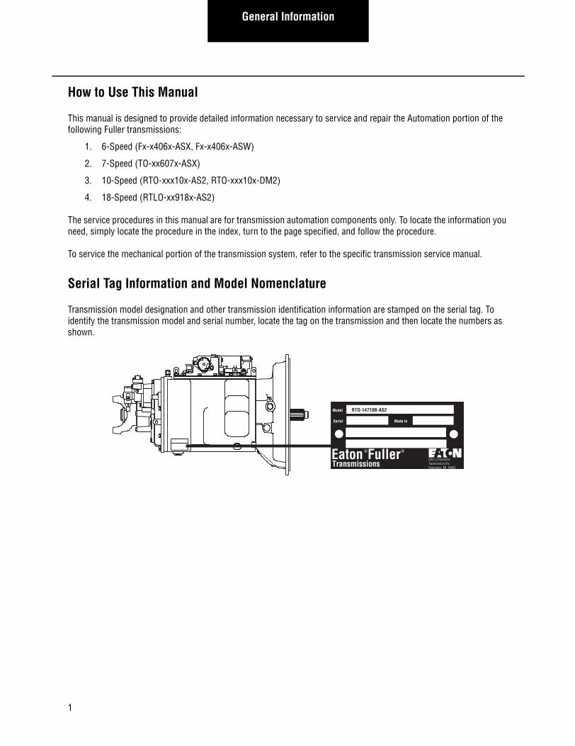
Serial Tag Information and Model Nomenclature
Transmission model designation and other transmission identification information are stamped on the serial tag. To identify the transmission model and serial number, locate the tag on the transmission and then locate the numbers as shown.
Model
Serial
EatonTransmissions
R
Made In
RTO-14710B-AS2
Eaton CorporationTransmission Div.Kalamazoo, MI. 49003
Fuller R
1

General InformationGeneral Inform
ation
Model Number
The model number gives basic information about the transmission and is explained below. Use this number when call-ing for service assistance or replacement parts.
Serial Number
The serial number is the sequential identification number of the transmission. Have the serial number available when calling for service assistance.
Bill of Material or Customer Number
This number may be located below the model and serial numbers. It is a reference number that is used by Eaton.
FullerOverdrive
Torque x 100Design Level
AutoShiftX-Inertia Brake
Forward SpeedsGear Ratio
F O 8 4 6 A0- X-
X
A S
Twin CountershaftOverdrive
Torque x 100Design Level
AutoShift
Gear RatioForward Speeds
T O 1 1 0 76- B - A S
R
RoadrangerTwin Countershaft
Overdrive
T O -
X - Inertia Brake
6-Speed
7-Speed
2
Torque x 100
Design Level
1 4 1 07 B - A S10-Speed
T
Overdrive
L O -R
Roadranger
Low Inertia
Twin Countershaft
2
Torque x 100
Design Level
2 - AutoShift II (Second Generation)
AutoShiftGear RatioForward Speeds
1 8 1 89 A - A S18-Speed
PREFIX KEY
F = FullerL = Low InertiaO = OverdriveR = RoadrangerT = Twin Countershaft
SUFFIX KEY
AS = AutoShiftX = Inertia Brake2 = AutoShift II
(Second Generation)
W-WetClutch
W=WetClutch
2 - AutoShift II (Second Generation)
AutoShift
Gear RatioForward Speeds
DM-Data Mechanical Clutch
DM=Data MechanicalClutch
2
General Information
Dry Clutch Models Only
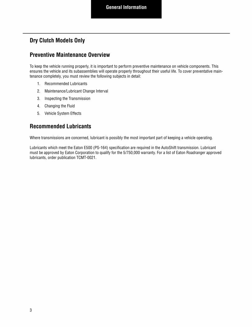
Preventive Maintenance Overview
To keep the vehicle running properly, it is important to perform preventive maintenance on vehicle components. This ensures the vehicle and its subassemblies will operate properly throughout their useful life. To cover preventative main-tenance completely, you must review the following subjects in detail:
1. Recommended Lubricants
2. Maintenance/Lubricant Change Interval
3. Inspecting the Transmission
4. Changing the Fluid
5. Vehicle System Effects
Recommended Lubricants
Where transmissions are concerned, lubricant is possibly the most important part of keeping a vehicle operating.
Lubricants which meet the Eaton E500 (PS-164) specification are required in the AutoShift transmission. Lubricant must be approved by Eaton Corporation to qualify for the 5/750,000 warranty. For a list of Eaton Roadranger approved lubricants, order publication TCMT-0021.
3

General InformationGeneral Inform
ation
Maintenance/Lubricant Change Intervals
Transmission filters should be changed durning regular lube intervals. Inspection of the transmission filter should be conducted during preventative maintenance checks for damage or corrosion. Replace as necessary.
Transmission inspections and lubricant changes depend on the type of lubricant used and whether the vehicle is used On or Off-highway.
On-highway Lubricant- Vehicles operated on paved roads, interstate highways, and turnpikes are designated as on-highway vehicles. Lubricant change and inspection intervals are the most generous for on-highway vehicles using syn-thetic lubricants.
Off-highway Lubricant- Vehicles operated in off-highway applications such as coal trucks or mining vehicles, it is more important to use time rather than mileage to keep the transmission within its proper preventative maintenance sched-ule. Off-highway applications are divided into two categories, severe and normal. “Severe off-highway” is the designa-tion used when there is excessive dust and dirt. “Normal off-highway” is for applications where dust and dirt are minimal.
Table 1: Lubricant Change and Inspection (On-highway)
Change Interval Description
Every 2500 miles Inspect lubricant level. Perform Transmission Inspection
Every 250,000 Change transmission lubricant and filter. (if equipped)
*The first lube change may be extended to 500,000 miles (800,000 km) when a transmission has been factory filled with a lube that is Eaton approved for 500,000 miles (800,000 km) (E-500, PS-164)
Table 2: Lubricant Change and Inspection (Off-highway)
Change Interval Description
Every 40 hours Inspect lubricant level. Perform Transmission Inspection
Every 1000 hours Change Transmission lubricant and filter (if equipped) where severe dirt conditions exist
Every 2500 hours Change Transmission lubricant and filter (if equipped) (Normal off-highway use.)
IMPORTANT
4
General Information
Transmission Inspection
When performing preventive maintenance (PM) inspections, several items must be checked. It is important to perform every step to ensure the transmission will meet its life expectancy. Proper PM consists of the following steps:
1. Check Lubricant Level
2. Inspect for Loose/Missing Bolts
3. Check for Air Leaks
4. Check for Lubricant Leaks
Check Lubricant Level
When checking the transmission lubricant there are two important points to know: where to check the lubricant and what the proper lubricant level is. Always be cautious when checking the transmission lubricant as it may be hot.
Checking Location- Checking the lubricant at the lubricant fill plug located on the left side of the main transmission case.
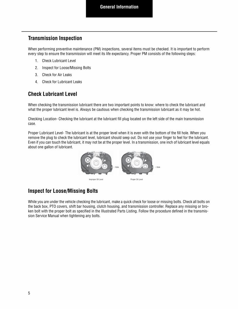
Proper Lubricant Level- The lubricant is at the proper level when it is even with the bottom of the fill hole. When you remove the plug to check the lubricant level, lubricant should seep out. Do not use your finger to feel for the lubricant. Even if you can touch the lubricant, it may not be at the proper level. In a transmission, one inch of lubricant level equals about one gallon of lubricant.
Inspect for Loose/Missing Bolts
While you are under the vehicle checking the lubricant, make a quick check for loose or missing bolts. Check all bolts on the back box, PTO covers, shift bar housing, clutch housing, and transmission controller. Replace any missing or bro-ken bolt with the proper bolt as specified in the Illustrated Parts Listing. Follow the procedure defined in the transmis-sion Service Manual when tightening any bolts.
Improper Oil Level
Hole
Proper Oil Level
Hole
5

General InformationGeneral Inform
ation
Check for Air Leaks
Two steps are required when checking for an air leak: inspection and repair.
Audible Inspection for Leaks- To find air leaks, make sure the vehicle air system has at least 90 PSI air pressure. Then, listen for leaks, making sure a vehicle leak is not mistaken for a transmission air leak.
Refer to Troubleshooting Procedures- Once you find an air leak, use the Troubleshooting Guide to isolate the air leak to the faulty component.
Check for Lubricant Leaks
A lubricant leak could cause a catastrophic transmission failure. Check for leaks first at the gasket surfaces, then the input shaft, the rear seal, and the transmission cooler.
Gaskets- Visually check each gasket to insure that no leak is present. Typically a moist spot is acceptable; however drips or larger wet areas are not. Check for leaks at the rear housing, PTO, shift bar housing, shift tower, and clutch housing gasket surfaces. It is also important to ensure that the leak is indeed coming from the transmission. Make sure the oil is not being blown back from the engine or another vehicle component.
Input Shaft- Check for leaks around the input shaft. Leaks in this area could be caused by a faulty gasket, input shaft, or pressurization of the main transmission case by the air system. If you find a leak at the input shaft, make sure the air system is not leaking into the case before looking for leaking gaskets.
Rear Seal- The rear seal is very important in maintaining lubricant in the transmission. If the seal is improperly installed or has failed, the transmission may experience a catastrophic failure. Check the rear seal by performing the following steps:
Visual Check for Leak- Visually inspect the rear seal for a leak. If a rear seal leak is suspected, proper isolation is neces-sary.
Verify the Leak Path- Other leaks may give the impression the rear seal is leaking. One possible cause is the vehicle speed sensor. Any lubricant leak above and in front of the rear seal could cause lubricant to collect around the seal. Wipe the seal with a clean rag, operate the vehicle, and recheck to verify the leak path. More information can be found in the Seal Maintenance Guide (TCSM-0912).
Transmission Cooler Leaks- If the vehicle is equipped with a transmission cooler, make sure there are no leaks at the lubricant cooler, hoses, and fittings of the cooler circuit.
6

General Information
Changing Lubricant
When it is time to change the transmission lubricant, there are only a few steps to follow: Draining and filling the trans-mission, draining and filling the cooler (if equipped), and changing the lubricant filter (if equipped). Remember to be careful when changing the transmission lubricant, as it may be hot.
Drain the Transmission
1. Locate the drain plug on the bottom of the transmission case.
2. Place a drain pan under the drain plug.
3. Remove the drain plug and allow the lubricant to drain completely.
4. Once drained, reinstall the drain plug and tighten to 45-55 lbs.ft. (61.0-74.6 N•m). Sealant is not required on the drain plug threads.
Drain the Cooler (if equipped)
1. Remove both cooler lines at the transmission.
2. Pressurize one line with 30 PSI of air pressure to force the lubricant out of the cooler.
3. Once drained, reconnect the coolant lines to the transmission. Make sure the lines are not crossed.
Fill the Transmission
1. Remove the transmission fill plug and fill the transmission with approved lubricant.
2. The transmission is full when the lubricant starts to flow out of the fill hole.
3. Replace the fill plug and tighten to 60-70 lbs.ft. (81.3-94.9 N•m).
Fill the Cooler (if equipped)
1. Place the transmission in neutral and start the vehicle.
2. Release the clutch to rotate the input shaft of the transmission, allowing the pump to fill the cooler.
3. Run the vehicle for one minute.
4. Shut off the vehicle, recheck the transmission lubricant level and add lubricant as required.
Change the “Spin-on” Filter (if equipped)
1. Remove the filter from the “spin-on” casting.
2. Catch any lubricant that seeps from the filter.
3. Clean the casting surface.
4. Install a new filter and hand tighten.
7
General InformationGeneral Inform
ation
Vehicle System Effects
Some vehicle systems can affect the transmission operation and possibly cause a failure. The air system is a major sys-tem that can affect the transmission components.
Air System- If the air system is not given recommended preventive maintenance, it can cause problems for the trans-mission system. Although the transmission has an Air Filter/Regulator, it can only protect the transmission from con-taminants for so long. This is why it is important to follow OEM recommendations for air system preventive maintenance. It is important to regularly drain air tanks and ensure lubricant is not being pumped into the system. It can cause corrosion or, in cold climates, it could freeze and prevent the shift mechanisms from operating. If lubricant is allowed into the system, it could fill the air system components and cause them to lose valuable air volume, slowing or preventing movement.
8

General Information
UltraShift™ HP Models
Preventive Maintenance Overview
To keep a vehicle running properly, it is very important to perform preventive maintenance on the vehicle components. This ensures the vehicle and its subassemblies will operate properly. To cover preventive maintenance completely, you must review the following subjects in detail.
1. Specified Lubricants
2. Maintenance/Lubricant Change Intervals
3. Inspecting the Transmission
4. Changing the Fluid
5. Clutch Calibration
Specified Lubricants
Where transmissions are concerned, lubrication is possibly the most important part of keeping a vehicle operating.
Synthetic Dexron III
Synthetic Dexron III must be used in the WetClutch portion of the transmission.
CD-50
CD-50 must be used in the gearbox portion of the transmission.
Maintenance/Lubricant Change Intervals
Transmission inspections and lubricant changes are outlined below.
For a list of Eaton Roadranger approved lubricants, order publication TCMT-0020.
For additional lubricant information, see TCMT-0021.
Table 1: Lubricant Inspection and Change Interval (On-highway)
Interval Description
Every 2,500 miles Inspect lubricant level. Perform Transmission Inspection.
Every 5 years or 500,000 miles, whichever occurs first
Change transmission lubricants and filters.
9

General InformationGeneral Inform
ation
Transmission Inspections
When performing preventive maintenance, several items must be checked. It is important to perform every step to ensure the transmission will meet its life expectancy. Proper preventative maintenance consists of the following steps:
1. Check WetClutch Lubricant Level
2. Check Gearbox Lubricant Level
3. Inspect for Loose/Missing Bolts
4. Check for Lubricant Leaks
Check Lubricant Level
When checking the WetClutch model, there are three important things to know: where to check the lubricants, what is the proper lubricant level, and what is the proper lubricant type. Always be cautious when checking the transmission fluid since it may be hot.
Checking WetClutch Lubricant
The WetClutch portion is checked using a dipstick located in the engine compartment.
Proper WetClutch Lubricant Level
WetClutch lubricant level should be checked when idling in neutral, with the transmission temperature between 60° F and 120° F (15.5° C and 48.8° C) and when the vehicle has been idling in neutral for at least two (2) minutes. Proper lubricant level is obtained when the lubricant is between the cold ADD mark and the cold FULL marks on the dipstick. Due to thermal expansion of the lubricant, it is not recommended to check the level when the transmission is above 120° F (48.8° C).
Checking Gearbox Lubricant
The gearbox portion is checked at the lubricant fill plug located on the right side of the gear case.
ADD COLD FULL (COLD 60-120 F) SYNTHETIC DEXRON III
10

General Information
Proper Gearbox Lubricant Level
The gearbox lubricant is at the proper level when it is even with bottom of the fill hole. When you remove the plug to check the lubricant level, lubricant should seep out. Do not use your finger to feel for the lubricant. Even if you can touch the lubricant, it may not be at the proper level. In a transmission, one inch of lubricant level equals about one gal-lon of lubricant.
Inspect for Loose/Missing Bolts
While you are under the vehicle checking the lubricant, make a quick check for loose or missing bolts. Check all bolts on the PTO cover, inertia brake, shift bar housing, clutch housing oil pan, output flange, and transmission controller. Replace any missing or broken bolt with the proper bolts as called out in the illustrated parts listing. Follow the proce-dure defined in the transmission service manual when tightening any bolts.
Check for Lubricant Leaks
A lubricant leak could cause a catastrophic transmission failure. Check for leaks at the gasket surfaces, lubricant lines, flywheel housing, rear seal, and the cooler.
Gaskets
Visually check each gasket to ensure that no leak is present. Typically, a moist spot is acceptable, however, drips or larger wet areas are not. Check for leaks at the rear housing, PTO cover, shift bar housing, clutch housing to main case, inertia brake, and clutch oil pan. It is also important to ensure that the leak indeed is coming from the transmission. Make sure the lubricant is not being blown back from the engine or another vehicle component.
Lubricant Lines
There are three external lines for lubricant on the UltraShift HP transmission. One lubricates the inertia brake and the other two are for the oil cooler. Check the lines to ensure they are not leaking.
Flywheel Housing/Clutch Housing
Check for leaks around the flywheel housing/clutch housing mating surface. A faulty seal or loose fittings could cause leaks in the area. The UltraShift HP transmission has what is called a “wet housing” which means that the clutch hous-ing is used as a sump for the WetClutch lubricant. Any leaks here could cause a transmission failure.
Transmission Cooler Leaks
Improper Oil Level
Hole
Proper Oil Level
Hole
11

General InformationGeneral Inform
ation
Ensure there are no leaks at the lubricant cooler, hoses, and fittings of the cooler circuit.
Changing the Lubricant
When it is time to change the transmission lubricant, there are only a few steps to follow:
• Draining and Filling the WetClutch portion
• Draining and Filling the Gearbox portion,
• Draining and Filling the Cooler,
• Changing the Lubricant Filters
Remember to be careful when changing the transmission lubricant, as it may be hot.
Drain the Transmission Gearbox and WetClutch Housing1. Locate the drain plugs at the bottom of the transmission gear case and on the clutch housing oil pan.
2. Place a drain pan under each drain plug.
3. Remove both drain plugs and allow the lubricants to drain completely.
4. Disconnect both cooler lines at the WetClutch housing.
5. Pressurize one line with 20 PSI until all lubricant is forced out of the cooler.
6. Reconnect both cooler lines.
WARNING
12

General Information
Change WetClutch Filters
Change the lubricant filters when the transmission lubricant is changed. Detailed information can be found on removal and replacement of the oil filters in this service manual.
Fill the Transmission1. Install the transmission gearbox drain plug and tighten to 45-55 lbs.ft. (61.0-74 N•m). Sealant is not required
on the drain plug threads.
2. Install the clutch housing oil pan drain plug and torque to 34-48 lbs.ft. (46-65N•m). Sealant is not required on the drain plug thread.
3. Fill the transmission gearbox with the recommended lubricant until the lubricant seeps out of the fill hole.
4. Install the fill plug and torque to 25-35 lbs.ft. (34-47 N•m).
5. Slowly fill the clutch through the dipstick tube with a maximum of 18 pints (8.5 liters) of the recommended lubricant.
6. Place the transmission in neutral position and apply the parking brakes. Start the engine and let idle for five (5) minutes, (this allows oil to fill the WetClutch system and cooling system), add oil as needed to obtain a level at the proper temperature range. Total oil quantity should be approximately 24 pints: this varies depending on the cooling system capacity.
7. Increase the engine idle slowly to 1500 RPM for two (2) minutes. Next, recheck the oil level at normal idle speed in neutral, again adding oil to obtain a level at the proper temperature range.
8. Replace the dipstick and tighten securely.
Clutch Calibration
The UltraShift HP system automatically provides for clutch wear. The system will initiate a clutch calibration once per vehicle power up, when certain vehicle conditions are right. Of these conditions, the most important ones include: when the engine is running at idle speed, during normal operating temperature, when the vehicle is stopped, and when neutral is selected on the Shift Control. During the calibration, the clutch is partially engaged until the engine begins to slightly lug down. It will then disengage the clutch and repeat this process several times. The calibration process usually takes as little as thirty seconds but can take as long as two (2) minutes. The calibration will be aborted when any position other than neutral is selected on the Shift Control.
If it appears that the vehicle is not engaging smoothly from a stop, it is possible that the clutch needs to be re-cali-brated. If it has not been previously calibrated during the current power up, stop the vehicle with the engine idling at its normal operating temperature and place the Shift Control in neutral and wait two (2) minutes. If the calibration is being performed you should hear the engine slightly lug down and then return to its no load condition several times.
If calibration does not occur a Power Down/Power Up will initiate a calibration.
13

General InformationGeneral Inform
ation
Oil Leak Inspection Process
Inspect for Oil Leak
Determine if it is a Weep or a Leak
Weep: Stained, damp, no drips, light oil film,dirt adhered to the contaminated area.
Leak: Extremely wet or dripping of oil in thecontaminated area.
Gasket Rear Seal Leak
1. Clean suspected oil weeparea with a clean dry clothor mild soluble degreaser.
2. Ensure lube is to properlevel.
3. Notify the customer that it is only a weep and it is notconsidered to be detrimentalto the life of the transmission.
4. Repair is complete.
1. Do not repair: Rear seal is designed to allow minimalseepage (refer to RoadrangerTCSM-0912 Seal MaintanceGuide).
2. Ensure lube is to properlevel.
1. Determine the origin of the leak path.2. If origin of leak is obvious skip to Step 3.3. If the origin of the oil leak is not obvious then use either of the two following steps to determine the oil leak:
Note: Do not use a high pressure spray washer to clean the area. Use of a high pressure spray may force contamination into the area of concern and temporarily disrupt the leak path. i. Clean area with a clean dry cloth or mild soluble degreaser and fill the transmission to the proper lube level. OR ii. Clean the area as noted above and insert tracer dye into the transmission lube and fill transmission to proper lube level.
Operate vehicle to normal transmission operating temperature and inspect the area for oil leak(s) visually or if tracer dye was introduced use an UVL (Ultraviolet Light) to detect the tracer dye’s point of origin.Note: When inspecting for the origin of the leak(s) make sure the assumed leak area is not being contaminated by a source either forward or above the identified area such as the engine, shift tower, shift bar housing, top mounted oil cooler, etc...
Once the origin of the leak is identified, repair the oil leak using proper repair procedures from the designated model service manual.
After the repair is completed, verify the leak is repaired and operate the vehicle to normaltransmission operating temperature.Inspect repaired area to ensure oil leak has been eliminated. If the leak(s) still occurs, repeat steps or contact the Roadranger Call Center at 1-800-826-4357.
Step 1
Step 2
Step 3
Step 4
14
15
Service Procedures
Lubricant Filter (UltraShift HP Models Only) – Remove
Special Instructions
None
Required Tools
• Basic Hand Tools
Removal
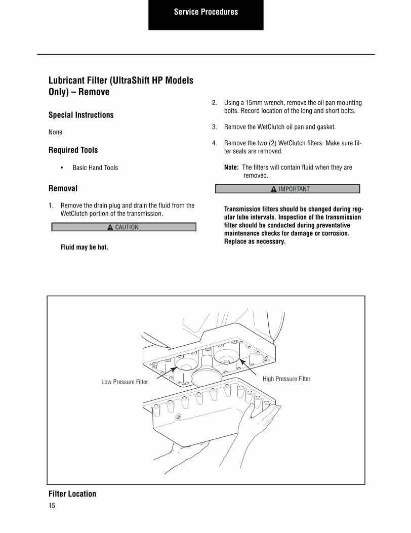
1. Remove the drain plug and drain the fluid from the WetClutch portion of the transmission.
Fluid may be hot.
2. Using a 15mm wrench, remove the oil pan mounting bolts. Record location of the long and short bolts.
3. Remove the WetClutch oil pan and gasket.
4. Remove the two (2) WetClutch filters. Make sure fil-ter seals are removed.
Note: The filters will contain fluid when they are removed.
Transmission filters should be changed during reg-ular lube intervals. Inspection of the transmission filter should be conducted during preventative maintenance checks for damage or corrosion. Replace as necessary.
CAUTION
IMPORTANT
Low Pressure Filter High Pressure Filter
Filter Location

16
Service ProceduresService Procedures
1
Remove Drain PlugDrain Fluid
2
Remove Oil PanMounting Bolts
3
Remove Oil Pan and Gasket
4
Remove Filters
15 mm Wrench
Wrench
Low Pressure Filter
High Pressure Filter
Lubricant Filter Removal

17
Service Procedures
Lubricant Filter (UltraShift HP Models Only) – Install
Special Instructions
Install each filter in its correct location.
Clean filter seal mating surfaces on the transmission.
Clean and remove all old gasket material from the mating surfaces of the clutch housing and the oil pan.
Required Tools
Basic Hand Tools
Installation
1. Lubricate each filter seal ring with synthetic Dexron III prior to installation.
2. Install the low-pressure filter and turn until seal touches. Then tighten 3/4 to 1 full turn.
3. Install the high-pressure filter and tighten to 25-30 lbs.ft. (34-41 N•m).
4. Install a new gasket and the WetClutch oil pan.
5. Using a 15mm wrench install the mounting bolts and tighten to 30-35 lbs.ft. (41-47 N•m) using a cross pattern.
Note: Put the long and short bolts back in their proper location.
6. Install the oil pan drain plug and tighten to 34-48 lbs.ft. (46-65 N•m).
Note: Fill the WetClutch portion with the proper fluid.
Final Check
Make sure the bolts are properly tightened.
Make sure the WetClutch portion is properly filled with the specified fluid.
Check for fluid leaks during and after operating the vehi-cle.
Transmission filters should be changed during regular lube intervals. Inspection of the transmission filter should be conducted during preventative maintenance checks for damage or corrosion. Replace as necessary.
IMPORTANT

18
Service ProceduresService Procedures
1
Lubricate SealRings
2
Install and Tighten Low Pressure Filter
3
Install and Torque High Pressure Filter 4
Install Oil Panand Gasket
5
Install and TorqueMounting Bolts
6
Install and TorqueDrain Plug
Seal Ring
Low Pressure Filter
High Pressure Filter
Pan Gasket
Drain Plug
Oil Pan
Torque Wrench
Torque Wrench
Mouting Bolts
Lubricant Filter Installation

19
Service Procedures
Rail Select Sensor – Remove
Special Instructions
While removing the hex key mounting screws, hold the sensor in place. Do not allow it to snap out of position.
Required Tools
• Basic Hand Tools
Removal
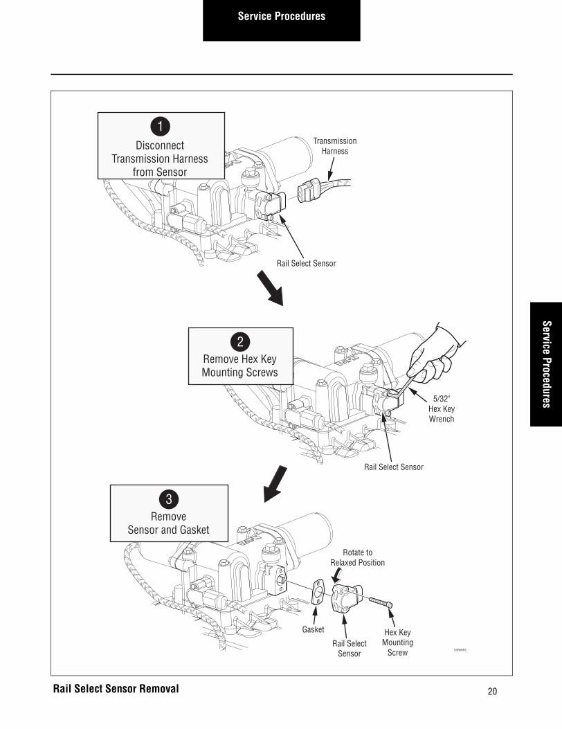
1. Disconnect the Transmission Harness from the Rail Select Sensor.
2. Using a 5/32” hex key wrench, remove the two (2) sensor hex key mounting screws.
Note: Carefully allow the sensor to rotate (not snap) to a relaxed position or the sensor can snap when the hex key mounting screws are removed.
3. Remove the sensor and gasket from the housing.
Rail SelectSensor
Rail Select Sensor Location
20
Service ProceduresService Procedures
Rail Select Sensor Removal
Gasket
Rail SelectSensor
Rotate toRelaxed Position
Hex KeyMounting
Screw
5/32"Hex KeyWrench
Rail Select Sensor
TransmissionHarness
Rail Select Sensor
1Disconnect
Transmission Harnessfrom Sensor
2Remove Hex KeyMounting Screws
3Remove
Sensor and Gasket
120RMVRS
21
Service Procedures
Rail Select Sensor – Install
Special Instructions
While installing the hex key mounting screws, hold the Rail Select Sensor in place. Do not allow it to snap out of position.
Torques given below are in pound-inches. Use care not to overtighten.
Required Tools
Basic Hand Tools
Installation
1. Align the sensor’s tab with the slot in the shifter housing. Then insert the Rail Select Sensor, with gasket, into its mounting location.
Note: Install the sensor so the connector opening faces the right side of the transmission.
2. Using a 5/32" hex key wrench, install the hex key mounting screws and tighten to 21-27 lbs.in. (2.4-3.1 N•m).
Note: Carefully hold the sensor in position while installing the hex key mounting screws or the sensor can snap.
3. Reconnect the Transmission Harness to the Rail Select Sensor.
Final Check
Make sure the gasket is installed between the sensor and the shifter housing.
Make sure the screws are tightened to specification.
Make sure all connections are tight.
Make sure the Transmission Harness is properly con-nected to the Gear Select Sensor.
Be sure to perform the Electric Shifter calibration proce-dure before operating the transmission.

22
Service ProceduresService Procedures
Gasket
Rail SelectSensor
Rotate toAlign Mounting
Holes
Hex KeyMounting Screw
5/32"Hex KeyWrench
Rail Select Sensor
Transmission Harness
Rail Select Sensor
2Install Hex Key
Mounting Screws
1Insert Sensorand Gasket
ReconnectTransmission Harness
to Sensor
3
120INSRS
Rail Select Sensor Installation

23
Service Procedures
Gear Select Sensor – Remove
Special Instructions
While removing the hex key mounting screws, hold the sensor in place. Do not allow it to snap out of position.
Required Tools
Basic Hand Tools
Removal
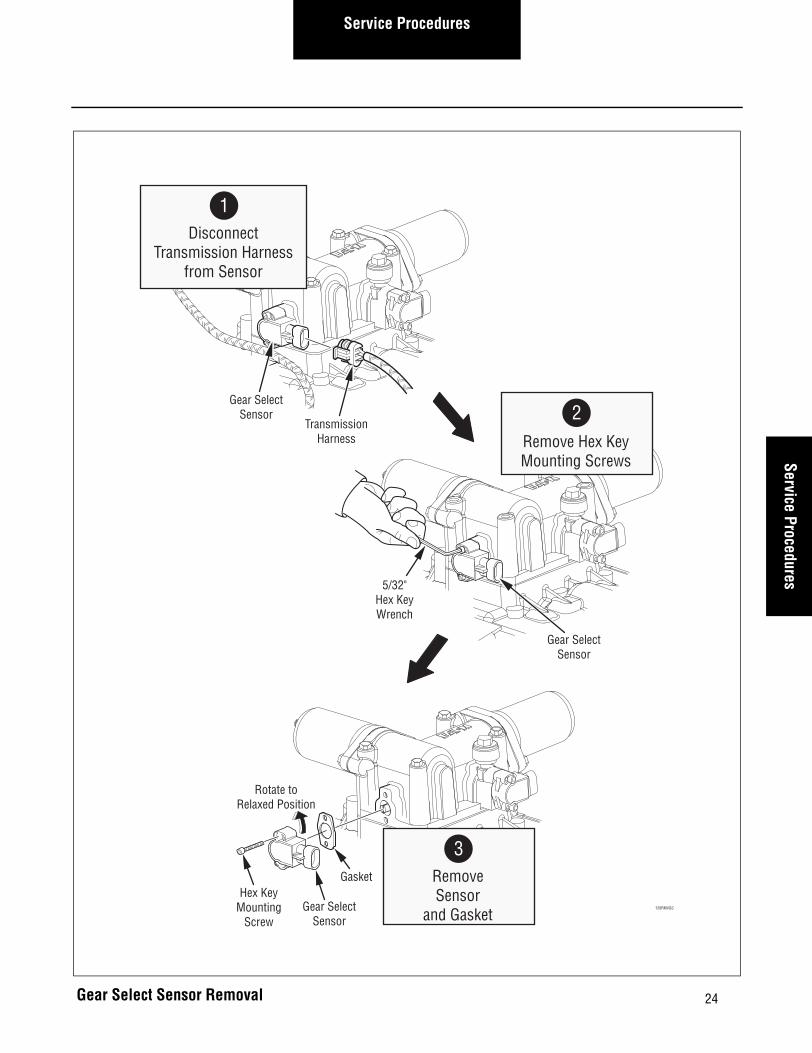
1. Disconnect the Transmission Harness from the Gear Select Sensor.
2. Using a 5/32” hex key wrench, remove the two (2) sensor hex key mounting screws.
Note: Carefully allow the sensor to rotate to a relaxed position, or the sensor can snap when the hex key mounting screws are removed.
3. Remove the sensor and gasket from the housing.
Gear SelectSensor
Gear Select Sensor Location
24
Service ProceduresService Procedures
Gasket
Gear SelectSensor
Hex KeyMounting
Screw
Gear SelectSensor
5/32"Hex KeyWrench
TransmissionHarness
Gear SelectSensor 2
Remove Hex KeyMounting Screws
1Disconnect
Transmission Harnessfrom Sensor
3RemoveSensor
and Gasket120RMVGS
Rotate toRelaxed Position
Gear Select Sensor Removal

25
Service Procedures
Gear Select Sensor – Install
Special Instructions
While installing the hex key mounting screws, hold the Gear Select Sensor in place. Do not allow it to snap out of position.
Torques given below are in pound-inches. Use care not to overtighten.
Install the sensor, so the connector opening faces the back of the transmission.
Required Tools
Basic Hand Tools
Installation
1. Align the sensor’s tab with the slot in the shifter housing. Then insert the Gear Select Sensor with gasket into its mounting location.
2. Using a 5/32" hex key wrench, install the two (2) hex key mounting screws and tighten to 21-27 lbs.in. (2.4-3.1 N•m).
Note: Carefully hold the sensor in position while installing the hex key mounting screws, or the sensor can snap.
3. Reconnect the Transmission Harness to the Gear Select Sensor.
Final Check
Make sure the gasket is installed between the sensor and the shifter housing.
Make sure the screws are tightened to specification.
Make sure all connections are tight.
Make sure the Transmission Harness is properly con-nected to the Gear Select Sensor.
Be sure to perform the Electric Shifter calibration proce-dure before operating the transmission.

26
Service ProceduresService Procedures
Gear Select Sensor Installation
Gasket
Gear SelectSensor
Hex KeyMounting
Screw
120INSGS
GearSelectSensor
5/32"Hex Key Wrench
TransmissionHarness
GearSelectSensor
2Install Hex Key
Mounting Screws
1Insert Sensorand Gasket
3Reconnect
Transmission Harnessto Sensor
Rotate to AlignMounting Holes
27
Service Procedures
Input Shaft Speed Sensor – Remove
Special Instructions
Drain the transmission lubricant on 6-Speed transmis-sions before removing the Input Shaft Speed Sensor.
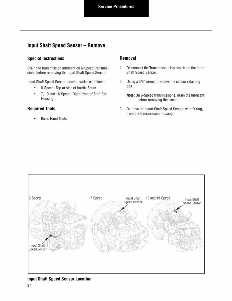
Input Shaft Speed Sensor location varies as follows:
• 6-Speed- Top or side of Inertia Brake
• 7, 10 and 18-Speed- Right front of Shift Bar Housing.
Required Tools
• Basic Hand Tools
Removal
1. Disconnect the Transmission Harness from the Input Shaft Speed Sensor.
2. Using a 3/8" wrench, remove the sensor retaining bolt.
Note: On 6-Speed transmissions, drain the lubricant before removing the sensor.
3. Remove the Input Shaft Speed Sensor, with O-ring, from the transmission housing.
Input ShaftSpeed Sensor
6-Speed 7-Speed 10 and 18-Speed Input ShaftSpeed Sensor
Input ShaftSpeed Sensor
Input Shaft Speed Sensor Location

28
Service ProceduresService Procedures
Input Shaft Speed Sensor Removal
InputShaftSpeedSensor
Retaining Bolt
3/8" WrenchTransmission
Harness
1Disconnect
Transmission Harness
2Remove
Retaining Bolt
3Remove
Speed Sensor
120RMVIS
RetainingBolt
Input Shaft Speed Sensor
3/8" WrenchTransmissionHarness
1Disconnect
Transmission Harness
2Remove
Retaining Bolt3
RemoveSpeed Sensor
7, 10 and 18-Speed
6-Speed

29
Service Procedures
Input Shaft Speed Sensor – Install
Special Instructions
Clean the mounting surface on the housing and remove any burrs or sharp edges.
Lubricate the O-ring with Eaton Fuller silicone #71214 or equivalent.
Input Shaft Speed Sensor location varies as follows:
• 6-Speed- Top or side of Inertia Brake
• 7, 10 and 18-Speed- Right front of Shift Bar Housing.
Required Tools
• Basic Hand Tools
Installation
1. Using a smooth, twisting motion, fully insert the sensor in the transmission housing opening.
2. Using a 3/8" wrench, install the retaining bolt and tighten to 8-10 lbs.ft. (10.8-13.6 N•m).
3. Reconnect the Transmission Harness to the Input Shaft Speed Sensor.
Note: Fill the transmission with lubricant.
Final Check
Make sure the transmission is properly filled with lubri-cant.
Make sure the retaining bolt is properly tightened.
Make sure the Transmission Harness is properly con-nected to the Input Shaft Speed Sensor.

30
Service ProceduresService Procedures
Input ShaftSpeed Sensor
RetainingBolt
3/8" WrenchTransmission Harness
3Reconnect
Transmission Harness
1Insert
Speed Sensor
2Install
Retaining Bolt
Input ShaftSpeed Sensor
RetainingBolt
3/8" WrenchTransmission Harness
3Reconnect
Transmission Harness
1Insert
Speed Sensor
2Install
Retaining Bolt
6-Speed
7, 10 and 18-Speed
Input Shaft Speed Sensor Installation

31
Service Procedures
Main Shaft Speed Sensor – Remove
Special Instructions
None
Required Tools
Basic Hand Tools
Removal
1. Disconnect the Transmission Harness from the Main Shaft Speed Sensor.
2. Using a 3/8” wrench, remove the sensor retaining bolt.
3. Remove the sensor, with O-ring, from the transmis-sion housing.
120LOC13
Main ShaftSpeed Sensor
Main Shaft Speed Sensor Location

32
Service ProceduresService Procedures
Main Shaft Speed Sensor Location
120RMVMI
Main ShaftSpeed Sensor
Retaining Bolt
3/8" Wrench
Main ShaftSpeed Sensor
TransmissionHarness
1Disconnect
Transmission Harness
2Remove
Retaining Bolt
3Remove
Speed Sensor

33
Service Procedures
Main Shaft Speed Sensor – Install
Special Instructions
Clean the mounting surface on the housing and remove any burrs or sharp edges.
Lubricate the O-ring with Eaton Fuller silicone #71214 or equivalent.
Required Tools
Basic Hand Tools
Installation
1. Using a smooth, twisting motion, fully insert the Main Shift Speed Sensor in the transmission hous-ing opening.
2. Using a 3/8” wrench, install the retaining bolt and tighten to 8-10 lbs.ft. (10.8-13.6 N•m).
3. Reconnect the Transmission Harness to the Sensor.
Final Check
Make sure the retaining bolts are properly tightened.
Make sure the Transmission Harness is properly con-nected to the Main Shaft Speed Sensor.

34
Service ProceduresService Procedures
120RMVMI
Main ShaftSpeed Sensor
Retaining Bolt
3/8" Wrench
Main ShaftSpeed Sensor
TransmissionHarness
3Reconnect
Transmission Harness
2Install
Retaining Bolt
1Insert
Speed Sensor
Main Shaft Speed Sensor Installation

35
Service Procedures
Output Shaft Speed Sensor – Remove
Special Instructions
The Output Shaft Speed Sensor location may vary depending on OEM design specifications. The sensor may be located at the 12 o’clock (shown in Figure 13), 10 o’clock, or 6 o’clock position on the Output Shaft Hous-ing.
The 10 and 18-Speed transmissions have an exposed tone ring on the output shaft. However, the service pro-cedure for the Output Shaft Speed Sensor is the same for all models.
Required Tools
Basic Hand Tools
Removal
1. Disconnect the Transmission Harness from the Out-put Shaft Speed Sensor.
2. Using a wrench, remove the sensor retaining bolt. Retaining bolt size varies as follows:
a. 6 and 7-Speed - Use a 3/8” wrench
b. 10 and 18-Speed - Use a 13mm wrench.
3. Remove the sensor, with O-ring, from the transmis-sion housing.
10 &18-Speed
Output ShaftSpeed Sensor
6 and 7-Speed
Output ShaftSpeed Sensor
Output Shaft Speed Sensor Location

36
Service ProceduresService Procedures
Output ShaftSpeed Sensor
RetainingBolt
13mm Wrench
Output ShaftSpeed SensorTransmission Harness
1Disconnect
Transmission Harnessfrom Speed Sensor
2Remove
Retaining Bolt
3Remove
Speed Sensor
120RMVMI
10 & 18-Speed
Output Shaft Speed Sensor Removal
Output ShaftSpeed Sensor
Retaining Bolt
3/8" Wrench
Ouptut ShaftSpeed Sensor
TransmissionHarness
1Disconnect
Transmission Harnessfrom Speed Sensor
2Remove
Retaining Bolt
3Remove
Speed Sensor
120RMVMI
6 & 7-Speed
Output ShaftSpeed Sensor
RetainingBolt
13mm Wrench
Output ShaftSpeed SensorTransmission Harness
1Disconnect
Transmission Harnessfrom Speed Sensor
2Remove
Retaining Bolt
3Remove
Speed Sensor
120RMVMI
10 & 18-Speed
37
Service Procedures
Output Shaft Speed Sensor – Install
Special Instructions
Clean the mounting surface on the housing and remove any burs or sharp edges.
Required Tools
Basic Hand Tools
Installation
1. Using a smooth, twisting motion, fully insert the Output Shaft Speed Sensor in the transmission housing opening.
Note: Lubricate the O-ring with Eaton Fuller silicon #71214 or equivalent.
2. Using a wrench, install the retaining bolt and tighten as follows:
a. 6 and 7-Speed- Use a 3/8” wrench and tighten to 8-10 lbs.ft. (10.8-13.6 N•m).
b. 10 and18-Speed- Use a 13mm wrench and tighten to 15-19 lbs.ft. (20.3-25.8 N•m).
3. Reconnect the Transmission Harness to the Output Shaft Speed Sensor.
Final Check
Make sure the retaining bolts are properly tightened.
Make sure the Transmission Harness is properly con-nected to the Main Shaft Speed Sensor.

38
Service ProceduresService Procedures
Output ShaftSpeed Sensor
Retaining Bolt
3/8" Wrench
Output ShaftSpeed Sensor
TransmissionHarness
3Reconnect
Transmission Harness
2Install
Retaining Bolt
1Insert
Speed Sensor
120RMVMI
6 & 7-Speed
Output ShaftSpeed SensorRetaining Bolt
13mm Wrench
Output ShaftSpeed Sensor
TransmissionHarness
3Reconnect
Transmission Harness
2Install
Retaining Bolt
1Insert
Speed Sensor
120INS18
10 &18-Speed
Output Shaft Speed Sensor Installation

39
Service Procedures
Range Valve – Remove
Special Instructions
The Range Valve may be difficult to remove from the housing because of the O-rings.
Do not use a hammer to loosen the Range Valve in the housing.
Required Tools
Basic Hand Tools
Removal
1. Relieve system air pressure by draining the air tanks on the vehicle. When air pressure is relieved discon-nect the Transmission Harness from the Range Valve assembly.
2. Using a 5/16” wrench, remove the four (4) mounting capscrews.
3. Lift and remove the Range Valve from the housing.
Note: The Range Valve may be difficult to remove from the housing.
120LOC15
RangeValve
Range Valve Location

40
Service ProceduresService Procedures
Range Valve Removal
Range ValveO-Ring
Mounting Capscrew5/16" Wrench
TransmissionHarness
Range Valve
2Remove Mounting
Capscrews
1Disconnect
Transmission Harnessfrom Range Valve
3Remove
Range Valve fromTransmission Housing

41
Service Procedures
Range Valve – Install
Special Instructions
Torques given below are in pound-inches. Use care not to overtighten.
Use care when installing O-rings
Required Tools
Basic Hand Tools
Installation
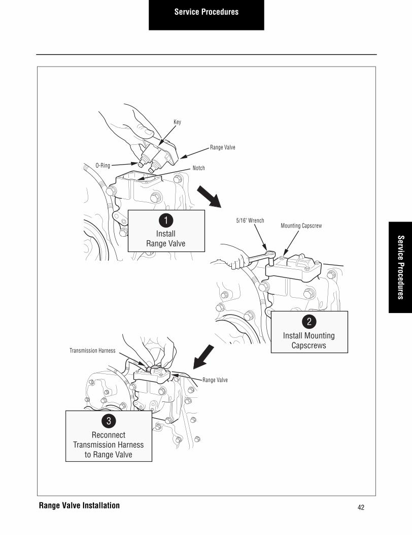
1. Install and push the Range Valve down into the housing.
Note: Lubricate O-ring with Eaton Fuller silicone #71214 or equivalent.
Note: The valve is keyed to fit its mounting location. Take care to align the key in the valve with the notch in the housing.
2. Using a 5/16” wrench, install the four (4) mounting capscrews and tighten to 21-27 lbs.in. (2.4-3.1 N•m) using a cross pattern.
3. Reconnect the Transmission Harness to the Range Valve and close all air tank drains.
Final Check
Make sure the mounting bolts are properly tightened.
Make sure the Transmission Harness is connected and locked.
Make sure all air tank drains are closed.
42
Service ProceduresService Procedures
Transmission Harness
Mounting Capscrew
Range Valve
Range Valve
O-Ring
Key
Notch
2Install Mounting
Capscrews
3Reconnect
Transmission Harnessto Range Valve
1Install
Range Valve
5/16" Wrench
Range Valve Installation

43
Service Procedures
Splitter Valve – Remove
Special Instructions
The Splitter Valve may be difficult to remove from the transmission housing because of the O-ring seals.
Do not use a hammer to loosen the Splitter Valve in the housing.
Required Tools
Basic Hand Tools
Removal
1. Relieve system air pressure by draining air tanks on the vehicle. When air pressure has been relieved, disconnect the Transmission Harness from the Split-ter Valve.
2. Using a 5/16” wrench, remove the four (4) mounting capscrews.
3. Lift and remove the Splitter Valve from the housing.
Note: The Splitter Valve may be difficult to remove from the housing.
120LOC14
SplitterValve
Splitter Valve Location

44
Service ProceduresService Procedures
Splitter Valve Removal
TransmissionHarness
Splitter Valve
O-Ring
5/16" Wrench
Mounting Capscrew
1Disconnect
Transmission Harnessfrom Splitter Valve
2Remove Mounting
Capscrews
3Remove
Splitter Valvefrom Housing
Splitter Valve

45
Service Procedures
Splitter Valve – Install
Special Instructions
Torques given below are in pound-inches. Use care not to overtighten.
Required Tools
Basic Hand Tools
Installation
1. Install and push the Splitter valve down into the housing.
Note: Lubricate O-rings with Eaton Fuller silicone #71214 or equivalent.
Note: The valve is keyed to fit its mounting location. Take care to align the key in the valve with the notch in the housing.
2. Using a 5/16” wrench, install the (4) mounting cap-screws and tighten to 21-27 lbs.in. (2.4-3.1 N•m) using a cross pattern.
3. Reconnect the Transmission Harness to the Splitter Valve and close all air tank drains.
Final Check
Make sure the mounting capscrews are properly tight-ened.
Make sure the Transmission Harness is connected and locked.
Make sure all air tank drains are closed.

46
Service ProceduresService Procedures
TransmissionHarness
5/16" Wrench
Notch
2Install Mounting
Capscrews
3Reconnect
Transmission Harnessto Splitter Valve
Splitter Valve
O-Ring
1Install
Splitter Valve
Key
Mounting Capscrew
Splitter Valve Installation

47
Service Procedures
Air Filter/Regulator – Remove
Special Instructions
The Air Filter/Regulator has two (2) O-rings located between the Air Filter/Regulator and the Range Cylinder Cover.
Required Tools
Basic Hand Tools
Removal
1. Relieve system air pressure by draining all air tanks on the vehicle. Then, using a 7/16” wrench, remove the two (2) mounting capscrews.
2. Remove the Air Filter/Regulator assembly and two (2) O-rings located in the recesses of the Range Cyl-inder Cover.
120LOC16
AirFilter/Regulator
Air Filter/Regulator Location

48
Service ProceduresService Procedures
Air Filter/Regulator Removal
O-Rings
MountingCapscrews
7/16" Wrench
Air Filter/Regulator
2
Remove Air Filter/Regulator
and O-Rings
1
Remove Mounting Capscrews
49
Service Procedures
Air Filter/Regulator – Install
Special Instructions
The Air Filter/Regulator has (2) O-rings located between the Air Filter/Regulator and the Range Cylinder Cover.
Required Tools
Basic Hand Tools
Installation
1. Press the O-rings into the recesses in the Range Cyl-inder Cover.
Note: Lubricate O-rings with Eaton Fuller silicone #71214 or Equivalent.
2. Install the Air Filter/Regulator:
a. Apply Eaton Fuller sealant #71205 or equivalent to the two (2) mounting capscrews.
b. Position the Air Filter/Regulator over the O-rings.
c. Insert the capscrews into the Air Filter/Regulator mounting holes.
d. Using a 7/16” wrench, install the two (2) mount-ing capscrews and tighten to 8-12 lbs.ft. (10.8-16.3 N•m).
Final Check
Make sure the mounting capscrews are properly tight-ened.
Make sure all air supply fittings are tight.
Make sure all air tank drains are closed.

50
Service ProceduresService Procedures
O-Rings
MountingCapscrews
7/16" Wrench
Air Filter/Regulator
1
Install O-Rings inRange Cylinder Cover
2
InstallAir Filter/Regulator
Air Filter/Regulator Installation

51
Service Procedures
Inertia Brake (6-Speed) – Remove
Special Instructions
None
Required Tools
Basic Hand Tools
Removal
1. Drain the lubrication from the transmission and dis-connect the Transmission Harness from the Input Shaft Speed Sensor and the Inertia Brake coil.
2. Using a 3/8” wrench, remove the Input Shaft Speed Sensor.
3. Using a 7/8” wrench, remove the lubricant supply line from the Inertia Brake.
The Inertia Brake is heavy. Be prepared to handle the weight of the Inertia Brake when the mounting bolts are removed.
4. Using a 9/16” wrench, remove the (6) mounting bolts from the Inertia Brake.
5. Remove the Inertia Brake, spacer, and gaskets from the transmission.
Note: The Inertia Brake will contain some lubricant.
CAUTION
Inertia Brake
6-Speed Inertia Brake Location

52
Service ProceduresService Procedures
6-Speed Inertia Brake Removal
Gasket
Gasket
Spacer
Inertia BrakeUse a
9/16" Wrench
7/8" Wrench
LubricantSupply
Line
3/8" Wrench
Input ShaftSpeed Sensor
InertiaBrakeCoil
TransmissionHarness
1Disconnect
Transmission Harness fromInput Shaft Speed Sensor,
and Inertia Brake Coil
2Remove
Speed Sensor
5Remove Inertia Brake,Spacer, and Gaskets
3Disconnect
Line
4Remove
Mounting Bolts

53
Service Procedures
Inertia Brake (6-Speed)– Install
Special Instructions
Clean and remove all old gasket material from the mating surfaces of the Inertia Brake spacer and transmission.
The Inertia Brake is heavy. Be prepared to handle the weight of the Inertia Brake until the mounting bolts are installed.
Required Tools
Basic Hand Tools
Installation
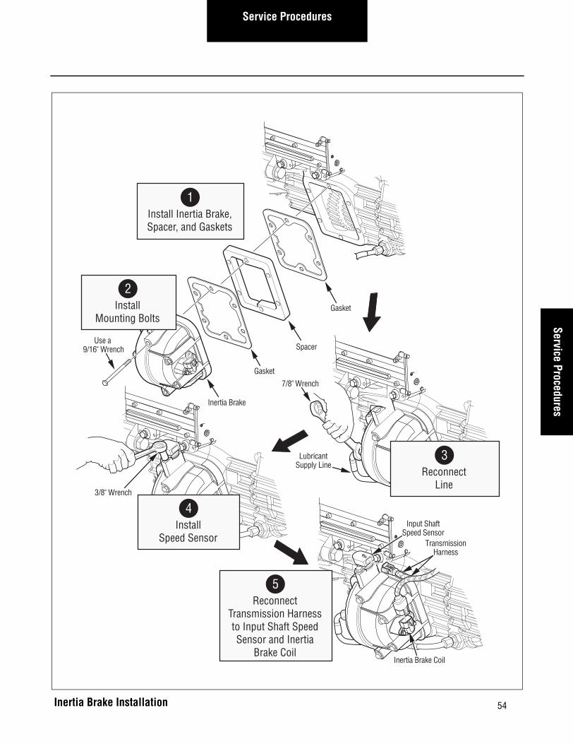
1. Install the Inertia Brake, spacer, and gasket being careful to align the Inertia Brake gear with the drive gear.
2. Using a 9/16” wrench, install the (6) mounting bolts. Tighten mounting bolts to 35-45 lbs.ft. (47.5-61.0 N•m) using a cross pattern.
3. Using a 7/8” wrench, reconnect the lubricant supply line to the Inertia Brake and tighten to 20-22 lbs.ft. (27-30 N•m).
4. Using a 3/8” wrench, install the Input Shaft Speed Sensor and tighten to 8-12 lbs.ft. (11-16 N•m).
5. Reconnect the Transmission Harness to the Input Shaft Speed Sensor and the Inertia Brake Coil.
Note: Fill the transmission with lubricant.
Final Check
Make sure the mounting bolts are properly tightened.
Make sure the lubricant supply line fitting is properly tightened.
Make sure the transmission is properly filled with lubri-cant.
Make sure the Transmission Harness is connected and locked.
Check for lubricant leaks after operating the vehicle.
CAUTION
54
Service ProceduresService Procedures
TransmissionHarness
Input ShaftSpeed Sensor
Inertia Brake Coil
3/8" Wrench
7/8" Wrench
LubricantSupply Line
Gasket
Gasket
Spacer
Inertia Brake
Use a 9/16" Wrench
5Reconnect
Transmission Harnessto Input Shaft SpeedSensor and Inertia
Brake Coil
2Install
Mounting Bolts
4Install
Speed Sensor
1Install Inertia Brake,Spacer, and Gaskets
3Reconnect
Line
Inertia Brake Installation

55
Service Procedures
Inertia Brake (7, 10, and 18-Speed) – Remove
Special Instructions
Drain the lubricant from the transmission. The Inertia Brake will still contain some lubricant.
Required Tools
Basic Hand Tools
Removal
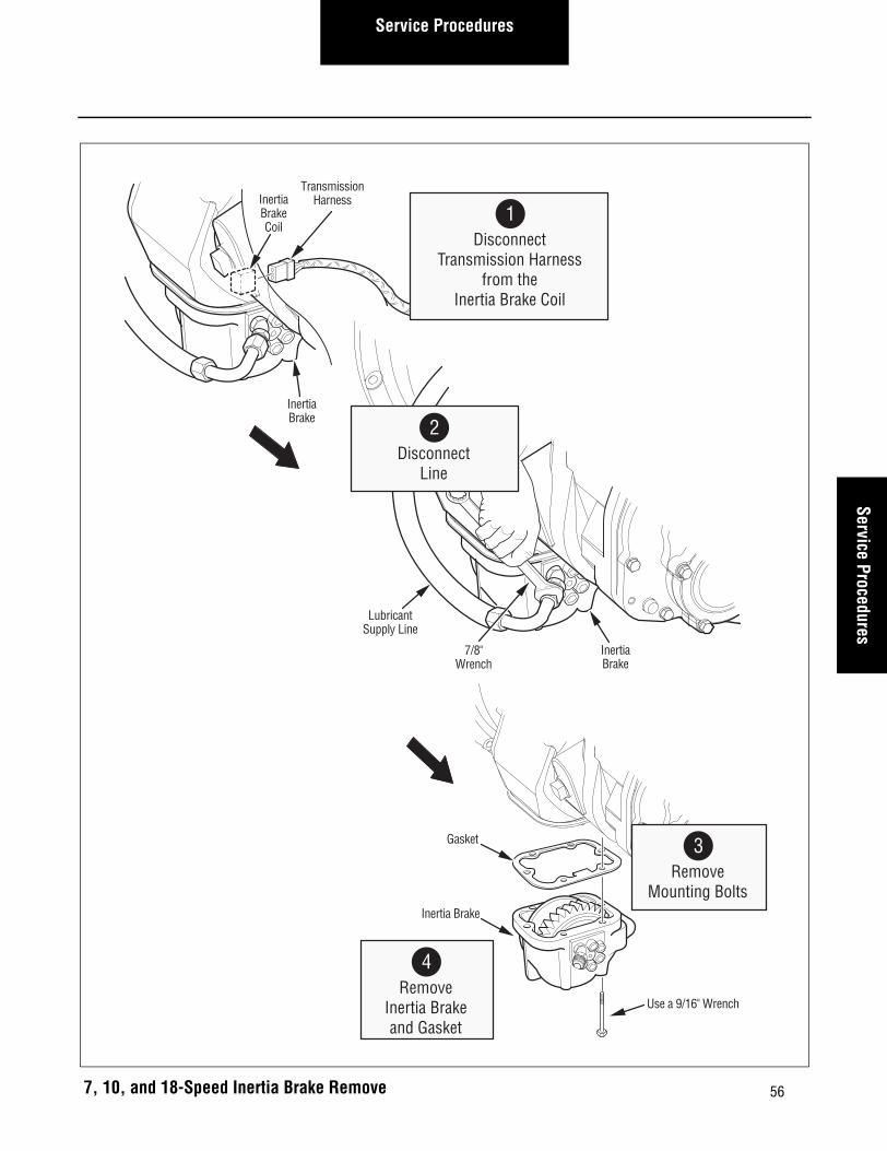
1. Disconnect the Transmission Harness from the Iner-tia Brake Coil.
2. Using a 7/8” wrench, disconnect the lubricant supply line from the Inertia Brake.
The Inertia Brake is heavy. Be prepared to handle the weight of the Inertia Brake when the mounting bolts are removed.
3. Using a 9/16” wrench, remove the six (6) mounting bolts from the Inertia Brake.
4. Remove the Inertia Brake and gasket from the trans-mission.
CAUTION
Inertia Brake
7, 10, and 18-Speed Inertia Brake Location
56
Service ProceduresService Procedures
7, 10, and 18-Speed Inertia Brake Remove
Inertia Brake
Gasket
Use a 9/16" Wrench
InertiaBrake
7/8"Wrench
LubricantSupply Line
InertiaBrake
TransmissionHarnessInertia
BrakeCoil
1Disconnect
Transmission Harnessfrom the
Inertia Brake Coil
3Remove
Mounting Bolts
4Remove
Inertia Brakeand Gasket
2Disconnect
Line

57
Service Procedures
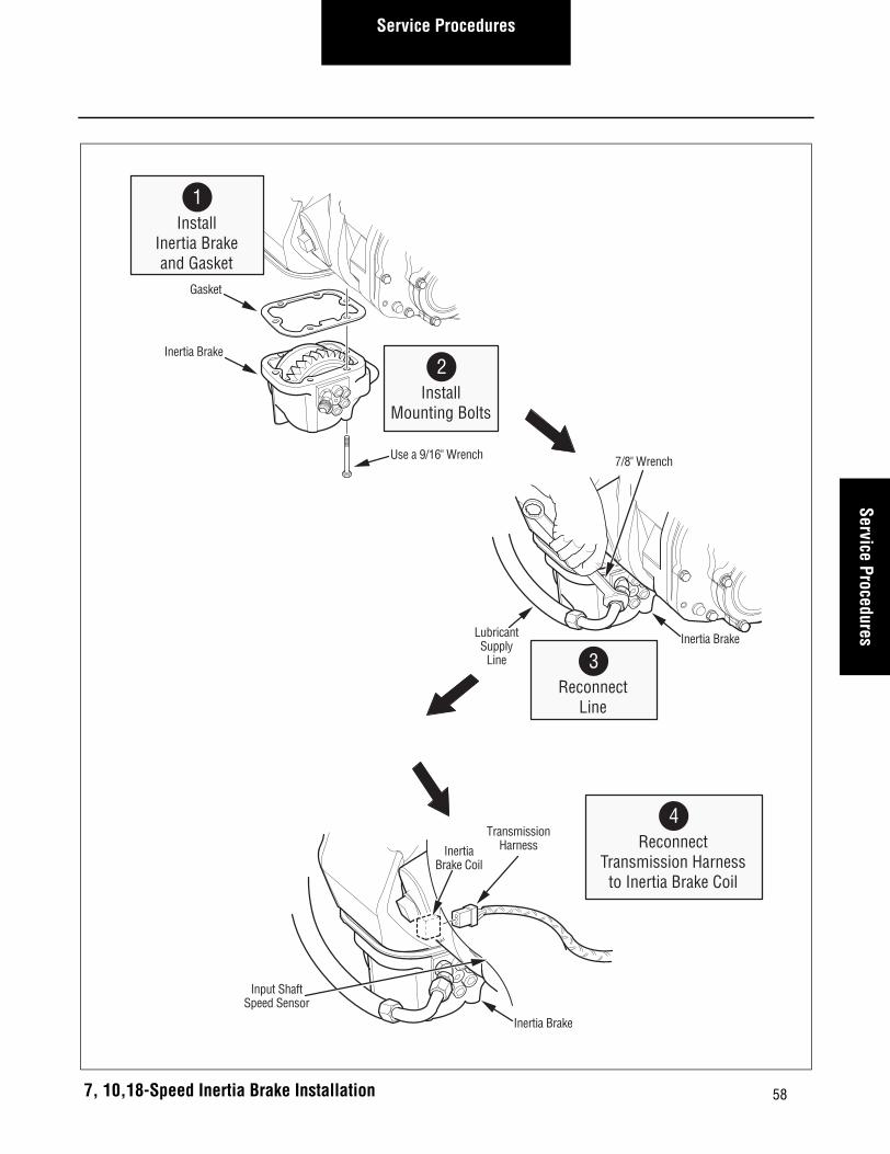
Inertia Brake (7, 10, and 18 Speed) – Install
Special Instructions
None
Required Tools
Basic Hand Tools
Installation
1. Install the Inertia Brake and gasket, being careful to align the Inertia Brake gear with the drive gear.
Note: Clean and remove all old gasket material from the mating surfaces of the Inertia Brake and transmission.
The Inertia Brake is heavy. Be prepared to handle the weight of the Inertia Brake until the mounting bolts are installed.
2. Using a 9/16” wrench, install the six (6) mounting bolts. Tighten mounting bolts to 35-45 lbs.ft. (47.5-30 N•m) using a cross pattern.
3. Using a 7/8” wrench, reconnect the lubricant supply line to the Inertia Brake and tighten to 20-22 lbs.ft. (27-30 N•m).
4. Reconnect the Transmission Harness to the Inertia Brake Coil.
Note: Fill the transmission with lubricant.
Final Check
Make sure the mounting bolts are properly tightened.
Make sure the lubricant supply line is properly tightened.
Make sure the transmission is properly filled with lubri-cant.
Make sure the Transmission Harness is connected and locked.
Check for lubricant leaks after operating the vehicle.
CAUTION
58
Service ProceduresService Procedures
Inertia Brake
Gasket
Use a 9/16" Wrench
Inertia Brake
7/8" Wrench
LubricantSupply
Line
Inertia Brake
TransmissionHarnessInertia
Brake Coil
Input ShaftSpeed Sensor
4Reconnect
Transmission Harnessto Inertia Brake Coil
2Install
Mounting Bolts
1Install
Inertia Brakeand Gasket
3Reconnect
Line
7, 10,18-Speed Inertia Brake Installation

Service Procedures
59
Inertia Brake Relocation Instructions 8 to 6 Bolt PTO Opening--Remove
Special Instructions
None
Required Tools
• Basic Hand Tools
Removal
1. Disconnect the Transmission Harness from the Iner-tia Brake Coil and remove the tie straps restraining this harness branch.
Oil may be hot.
Note: Drain the lubricate front he transmission. Drain the lubricant from the Inertia Brake. On older product the Inertia Brake will still remain full of lubricant (no drain plug).
Note: Use care not to damage the harness.
2. Disconnect the lubricant supply line from the Inertia Brake.
The Inertia Brake is heavy. Be prepared to handle the weight of the Inertia Brake when the mounting bolts are removed.
3. Remove the six (6) mounting bolts from the Inertia Brake.
4. Remove the Inertia Brake and gasket from the adapter plate.
5. Remove the eight (8) mounting bolts from the adapter plate.
6. Remove and discard the adapter plate and gasket from the transmission.
7. Remove the six (6) mounting bolts from the 6-bolt PTO cover.
8. Remove and discard the 6-bolt PTO cover and gas-ket from the transmission.
Note: Clean and remove all old gasket material from the mating surfaces of the Inertia Brake and transmission PTO coverings. Locate the har-ness push-in anchor point for reference dur-ing re-installation to 6-bolt opening.
CAUTION
CAUTION
Service ProceduresService Procedures
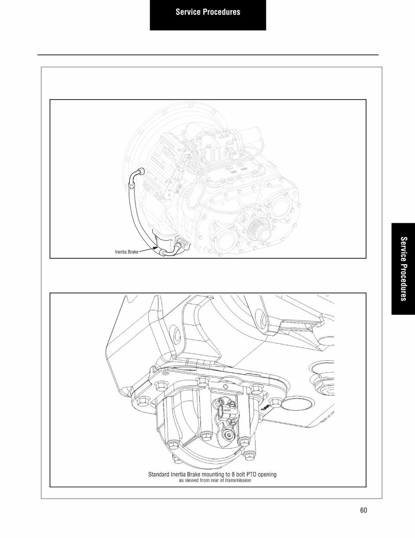
Inertia Brake
60

Service Procedures
Inertia Brake Relocation Instructions 8 to 6-Bolt PTO opening--Install
Special Instructions
None
Required Tools
Basic Hand Tools
Installation
1. Clean and thoroughly dry all mating surfaces (including the gasket) prior to assembly.
Note: The transmission Inertia Brake may be mounted to the 6-bolt PTO opening directly, or mounted utilizing a 6-bolt PTO Angle Adapter to assist in aiding chassis clearance.
2. If a 6-bolt PTO Angle Adapter is required, install the Angle Adapter to the 6-bolt PTO opening following the manufacturer’s instructions.
3. Inertia Brakes installed with the Angle Adapter require a new lubrication hose.
4. Using the six (6) 3/8 mounting bolts, install the Iner-tia Brake and gasket, being careful to align the Inertia Brake gear with the drive gear. Tighten mounting bolts to 40-45 lbs. ft. (54-61 N•m) using a cross pat-tern.
Note: When mounted directly, orient the Inertia Brake housing with hose connection forward/electrical connection rearward, same orienta-tion as 8-bolt. When mounted to a 6-bolt PTO Angle Adapter, orient the Inertia Brake hous-ing with hose connection rearward / electrical connection forward. Ensure gasket, Inertia Brake, and mating mounting faces are assembled dry (no lubricant or grease).
The Inertia Brake is heavy. Be prepared to handle the weight of the Inertia Brake until the mounting bolts are installed.
5. Reconnect the lubricant supply line to the Inertia Brake and tighten to 20-22 lbs. ft. (27-30 N•m).
6. Reroute and reconnect the transmission harness to the Inertia Brake Coil. Dress the harness along the transmission case from the Inertia Brake up to the top of the transmission. Install the harness push-in anchor to the threaded-hole anchor point in the Iner-tia Brake housing. Install tie wraps every 6-10 inches. The harness should not have sharp bends or be under tension.
7. Install the PTO to the 8-bolt PTO opening following the manufacture’s instructions.
Note: Fill the transmission with lubricant.
Final Check
• Make sure the mounting bolts are properly tightened.
• Make sure the lubricant supply line is properly tightened.
• Make sure the transmission is properly filled with lubricant.
• Make sure the transmission harness is con-nected and locked.
• Check for lubricant leaks after operating the vehicle.
• Check that the Inertia Brake has sufficient clear-ance to prevent contacting tanks, brackets, frame rails, exhaust, or any other part of the vehicle. Contacting anything when stationary or moving will cause damage to Inertia Brake, Angle Adapter, or other vehicle equipment.
CAUTION
61

Service ProceduresService Procedures
-
-
62
63
Service Procedures
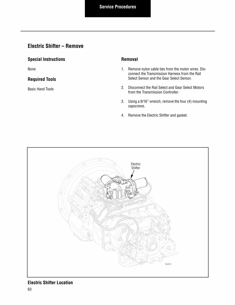
Electric Shifter – Remove
Special Instructions
None
Required Tools
Basic Hand Tools
Removal
1. Remove nylon cable ties from the motor wires. Dis-connect the Transmission Harness from the Rail Select Sensor and the Gear Select Sensor.
2. Disconnect the Rail Select and Gear Select Motors from the Transmission Controller.
3. Using a 9/16” wrench, remove the four (4) mounting capscrews.
4. Remove the Electric Shifter and gasket.
120LOC19
ElectricShifter
Electric Shifter Location

64
Service ProceduresService Procedures
Electric Shifter Removal
Electric Shifter
Shift Blocks
GasketShift Finger
9/16" Wrench
Rail SelectMotor Connector
Gear SelectMotor Connector
TransmissionController
Rail Select Sensor
Gear SelectSensor
TransmissionHarness
3Remove Mounting
Capscrews
1Disconnect
Transmission Harnessfrom Rail and Gear
Select Sensors
4Remove Electric
Shifter and Gasket
2Disconnect Rail andGear Motors from
Transmission Controller

65
Service Procedures
Electric Shifter – Install
Special Instructions
Make sure the three (3) sets of detent balls and springs are installed properly in the Shift Bar Housing.
Required Tools
Basic Hand Tools
Installation
1. Clean and remove old gasket material from the Shift Bar Housing. Position a new gasket at the Electric Shifter location.
Possible Pinch Point - Make sure battery is discon-nected before removal of XY shifter.
2. Check to ensure the shift blocks are in the neutral position, then move the shift finger to the center (neutral) location.
Note: If the shift finger is not properly aligned, the Electric Shifter will not fit properly at its mounting location.
Note: Apply Eaton sealant #71205 or equivalent to the mounting capscrews before installing.
3. Position the Electric Shifter on the Shift Bar Housing. Then using a 9/16” wrench, install the mounting capscrews and tighten in a cross pattern as follows:
a. 6-Speed (Aluminum Housing)- Tighten to 20-25 lbs.ft.(28-35 N•m).
b. 7, 10, and 18-Speed (Cast Iron Housing) Tighten to 34-45 lbs.ft. (48-61 N•m).
4. Reconnect the Rail Select and Gear Select Motors to the Transmission Controller.
5. Reconnect the Transmission Harness to the Rail Select and Gear Select Sensors. Using nylon ties, secure the motor wires to the transmission in their previous position.
Calibration
To operate properly, the system must be calibrated as follows:
1. Turn the ignition switch on and allow the trans-mission to power up.
2. Turn the ignition switch to off and wait two min-utes.
The Electric Shifter must be calibrated before the vehi-cle is placed into operation.
Final Check
Make sure the mounting capscrews are tightened to the correct specification.
Make sure all Electric Shifter connectors are securely attached.
Make sure the Transmission Harness is connected and locked.
Be sure to perform the calibration procedure before oper-ating the transmission.
WARNING
IMPORTANT

66
Service ProceduresService Procedures
Electric Shifter
Shift Blocks
GasketShift Finger
9/16" Wrench
Rail SelectMotor Connector
Gear SelectMotor Connector
TransmissionController
Rail Select Sensor
TransmissionHarness
Gear SelectSensor
3Install Mounting
Capscrews
5Reconnect
Transmission Harnessto Rail and GearSelect Sensors
1Clean Shift
Bar Housing andInstall New Gasket
2Check Shift Blocks
and Place Shift Fingerin Center Location
4Reconnect Rail and
Gear Motors toTransmission Controller
Possible Pinch Point- Make sure battery isdisconnected before removal of XY shifter.
WARNING
Electric Shifter Installation

67
Service Procedures
Transmission Controller – Remove
Special Instructions
When removing the Transmission Controller, take care not to bend the Transmission Controller locating bracket.
Required Tools
Basic Hand Tools
Removal
1. Disconnect the following connectors:
a. Disconnect the negative battery cable.
b. Disconnect the main power connector from the Transmission Controller.
c. Disconnect the Rail Select and Gear Select Motors from the Transmission Controller.
d. Using a 1/4” wrench, unscrew and disconnect the Transmission Harness 30-way connector and vehicle interface 18-way connector.
2. Using a 1/2” wrench, remove the two (2) mounting bolts.
3. Remove the Transmission Controller assembly from the locating studs.
TransmissionController
Transmission Controller Location

68
Service ProceduresService Procedures
Transmission Controller Removal
Locating Studs
TransmissionController
1/2" Wrench
Main Power Connector
Rail Select Connector
Gear Select Connector
Transmission Harness 30-Way Connector
1/4" Wrench
Vehicle Interface 18-Way Connector
1Disconnect
TransmissionController
Connectors
2Remove
Mounting Bolts
3Remove
Transmission Controller

69
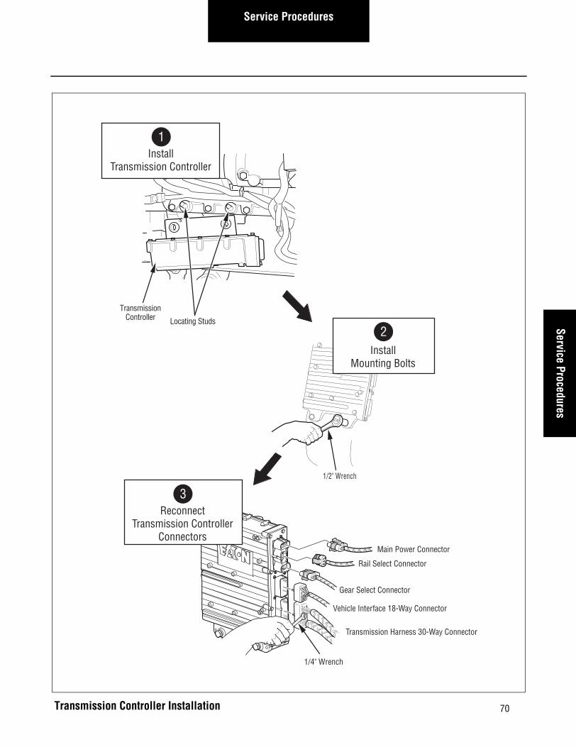
Service Procedures
Transmission Controller – Install
Special Instructions
Torques given below are in pound-inches. Use care not to overtighten.
Apply lubricant to the Transmission Controller mounting bracket locating studs on the main case top.
Required Tools
Basic Hand Tools
Installation
1. Position the Transmission Controller on the locating studs.
When attaching the Transmission Controller, take care not to bend the Transmission Controller locat-ing bracket.
2. Using a 1/2” wrench, install the two (2) Transmis-sion Controller mounting bolts and tighten to 20-25 lbs.ft. (27.1-33.9 N•m).
3. Reconnect the following connectors:
a. Using a 1/4” wrench, reconnect the Transmis-sion Harness 30-way connector and tighten to 7-13 lbs.in. (0.8-1.5 N•m).
b. Using a 1/4” wrench, reconnect the vehicle interface 18-way connector and tighten to 7-13 lbs.in. (0.8-1.5 N•m)
c. Reconnect the Gear Select Motor to the Trans-mission Controller.
d. Reconnect the Rail Select Motor to the Trans-mission Controller.
e. Reconnect the main power connector.
f. Reconnect the negative battery cable.
Calibration
To operate properly, the system must be calibrated as follows:
1. Turn the ignition switch on and allow the trans-mission to power up.
2. Turn the ignition off and wait two minutes.
Important: The Electric Shifter must be calibrated before the vehicle is placed in operation.
UltraShift HP- Perform clutch calibration: See UltraShift HP Models in this manual for details.
Final Check
Make sure the mounting bolts are properly tightened.
Make sure all Transmission Controller connectors are properly connected and locked or tightened.
Make sure the Electric Shifter Harness connectors are properly connected.
CAUTION
70
Service ProceduresService Procedures
Locating Studs
TransmissionController
1/2" Wrench
2Install
Mounting Bolts
1Install
Transmission Controller
Main Power Connector
Rail Select Connector
Gear Select Connector
Transmission Harness 30-Way Connector
Vehicle Interface 18-Way Connector
3Reconnect
Transmission ControllerConnectors
1/4" Wrench
Transmission Controller Installation

71
Service Procedures
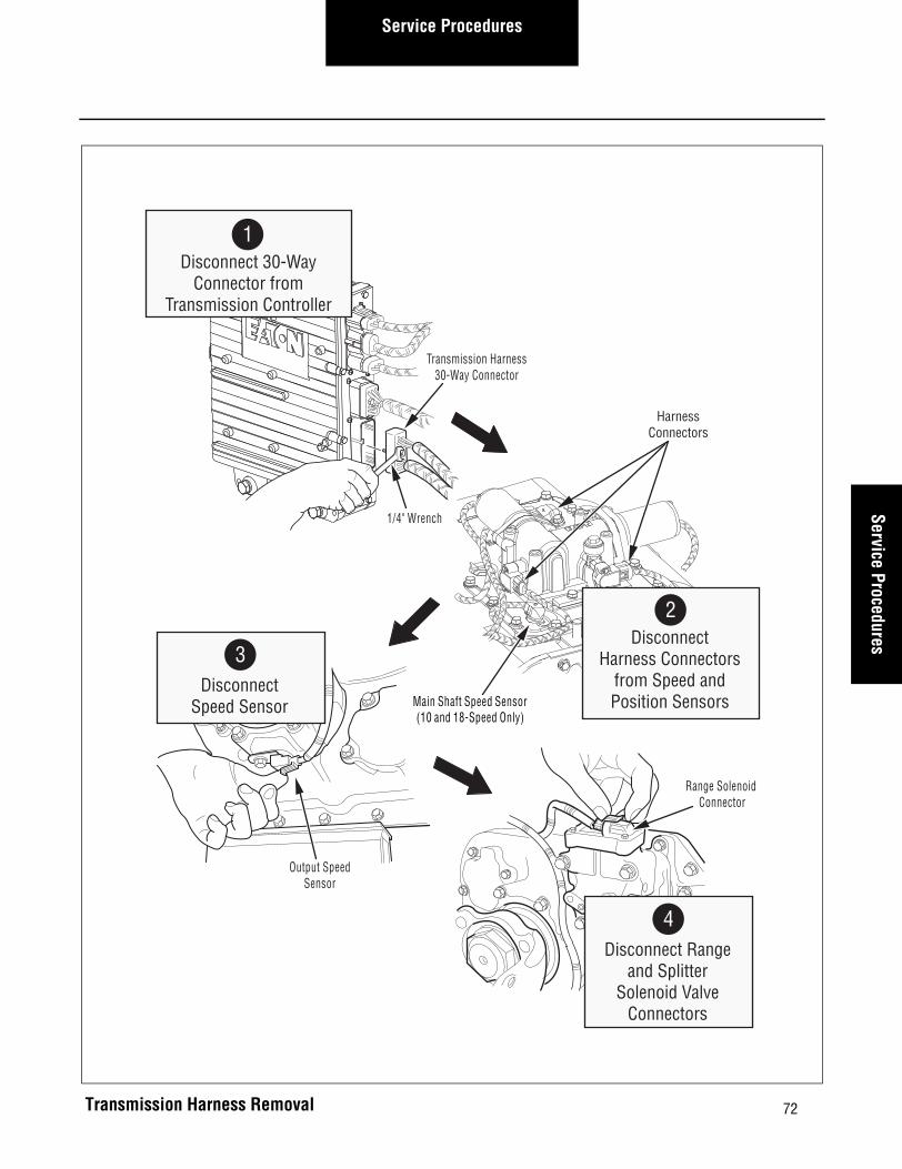
Transmission Harness – Remove
Special Instructions
None
Required Tools
Basic Hand Tools
Removal
1. Using a 1/4” wrench, disconnect the Transmission Harness 30-way connector.
2. Disconnect the following harness connectors:
a. Inertia Brake Coil (if equipped).
b. Input Shaft Speed Sensor (location may vary).
c. Main Shaft Speed Sensor (10 and 18-Speed only).
d. Gear Select Sensor and Rail Select Sensor.
e. WetClutch solenoid (if equipped).
3. Disconnect the Output Shaft Speed sensor (location may vary).
Transmission Harness30-Way Connector
Splitter Valve(18-Speed Only)
Input Speed Sensor(6-Speed Only)
Range Valve(10 and 18-Speed Only)
Rail SelectSensor
Main Shaft Speed Sensor(10 and 18-Speed Only)
Output ShaftSpeed Sensor
Input ShaftSpeed Sensor
(7, 10 and 18-Speed Only)
Inertia Brake Coil(Optional on 10 and 18-Speed)
GearSelect Sensor
Transmission Harness Location
72
Service ProceduresService Procedures
Transmission Harness Removal
Range Solenoid Connector
Output SpeedSensor
HarnessConnectors
Main Shaft Speed Sensor(10 and 18-Speed Only)
1/4" Wrench
Transmission Harness30-Way Connector
2Disconnect
Harness Connectorsfrom Speed andPosition Sensors
3Disconnect
Speed Sensor
4Disconnect Range
and SplitterSolenoid Valve
Connectors
1Disconnect 30-Way
Connector fromTransmission Controller
73
Service Procedures
Transmission Harness – Install
Special Instructions
None
Required Tools
Basic Hand Tools
Installation
1. If required, reconnect the Range and Splitter Sole-noids.
2. Reconnect the Output Shaft Speed Sensor.
3. Reconnect the following harness connectors:
a. Gear Select and Rail Select Sensor.
b. Main Shaft Speed Sensor (10 and 18-Speed only).
c. Input Shaft Speed Sensor (Location may vary).
d. Inertia Brake Coil (if equipped).
e. WetClutch solenoid (if equipped).
4. Using a 1/4” wrench, reconnect the Transmission Harness 30-way connector and tighten to 7-13 lbs.in. (0.8-1.5 N•m).
Final Check
Check all connections to make sure they are secure.
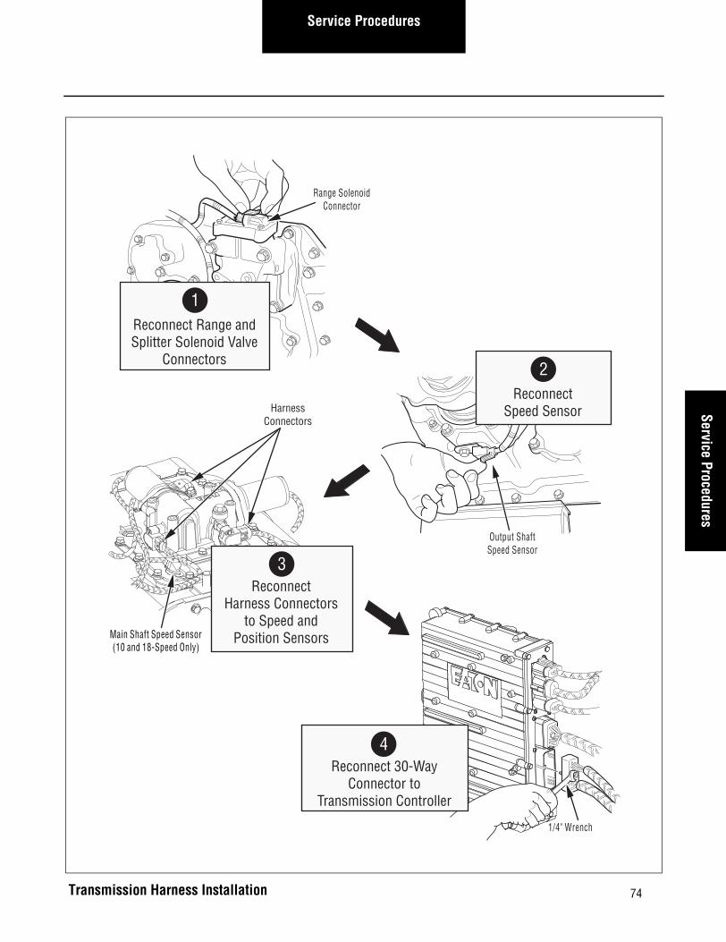
74
Service ProceduresService Procedures
Range SolenoidConnector
Output ShaftSpeed Sensor
HarnessConnectors
Main Shaft Speed Sensor(10 and 18-Speed Only)
2Reconnect
Speed Sensor
1Reconnect Range andSplitter Solenoid Valve
Connectors
3Reconnect
Harness Connectorsto Speed and
Position Sensors
1/4" Wrench
4Reconnect 30-Way
Connector toTransmission Controller
Transmission Harness Installation
75
Service Procedures
Gear Display – Remove
Special Instructions
The exact location varies depending on vehicle manufac-turer.
Required Tools
Basic Hand Tools
Removal
1. Follow the recommended OEM procedure to remove the dash panel that holds the Gear Display Unit.
2. Disconnect the dash harness from the Gear Display Unit.
3. Use a small flat bladed screwdriver to depress the tabs that hold the Gear Display Unit in the dash.

76
Service ProceduresService Procedures
Gear Display Removal
Gear Display
Dash Panel
Dash Harness
2Disconnect
Dash Harness fromGear Display
3Remove
Gear Display
1Remove
Dash Panel

77
Service Procedures
Gear Display – Install
Special Instructions
None.
Required Tools
Basic Hand Tools
Installation
1. Install the Gear Display Unit in the dash panel.
2. Reconnect the dash harness to the Gear Display Unit.
3. Follow the recommended OEM procedure to install the dash panel that holds the Gear Display Unit.
Final Check
Make sure the OEM Dash Harness is properly connected.

78
Service ProceduresService Procedures
Gear Display
Dash Panel
Dash Harness
2Reconnect
Dash Harnessto Gear Display
1Install
Gear Display
3Install
Dash Panel
Gear Display Installation
79
Service Procedures
Shift Control– Remove
Special Instructions
The exact location varies depending on vehicle manufac-turer.
Required Tools
Basic Hand Tools
Removal
1. Using a 1/4” wrench, loosen the retaining bolt and disconnect the 30-way connector from the back of the Shift Control.
2. Using a 11/32” wrench, remove the two (2) nuts and lock washers from the back of the Shift Control.

80
Service ProceduresService Procedures
Shift Control Removal
11/32"Wrench
MountingSurface
Lockwasher
Nut
30-WayConnector
Shift Control
1/4"Wrench
Shift Control
MountingSurface
2RemoveNuts and
Lockwashers3
RemoveShift Control
1Remove
30-Way Connector

81
Service Procedures
Shift Control – Install
Special Instructions
Torques given below are in pound-inches. Be careful not to over tighten the mounting hardware.
Required Tools
Basic Hand Tools
Installation
1. Install the Shift Control in its mounting location.
2. Using a 11/32” wrench, install the two (2) lock washers and nuts and tighten to 14-16 lbs.in. (1.6-1.8 N•m).
3. Using a 1/4” wrench, reconnect the 30-way connec-tor to the back of the Shift Control and tighten to 20-30 lbs.in. (2.3-3.4 N•m).

82
Service ProceduresService Procedures
Shift Control
MountingSurface
11/32"Wrench
MountingSurface
Lockwasher
Nut
Shift Control
1/4" Wrench
30-WayConnector
2Install
Lockwashersand Nuts
1Install
Shift Control
3Reconnect
30-Way Connector
Shift Control Installation

83
Service Procedures
Transmission – Remove
Special Instructions
The exact procedure varies depending on vehicle manu-facturer.
Required Tools
Basic Hand Tools
Removal
1. Follow the recommended OEM procedure to remove the transmission.
transremoveover
Transmission Removal

84
Service ProceduresService Procedures
Transmission – Install
Special Instructions
Adjust clutch as needed
UltraShift HP- Perform clutch calibration as needed.
Required Tools
Basic Hand Tools
Procedure
1. Follow the recommended OEM procedure to install the transmission.
Final Check
Make sure that the capscrews are tightened to specifica-tion.
Make sure that all connections are tight.
UltraShift HP transmissions- Be sure to perform the clutch calibration procedure before operating the trans-mission. See UltraShift HP Models in this manual for details.
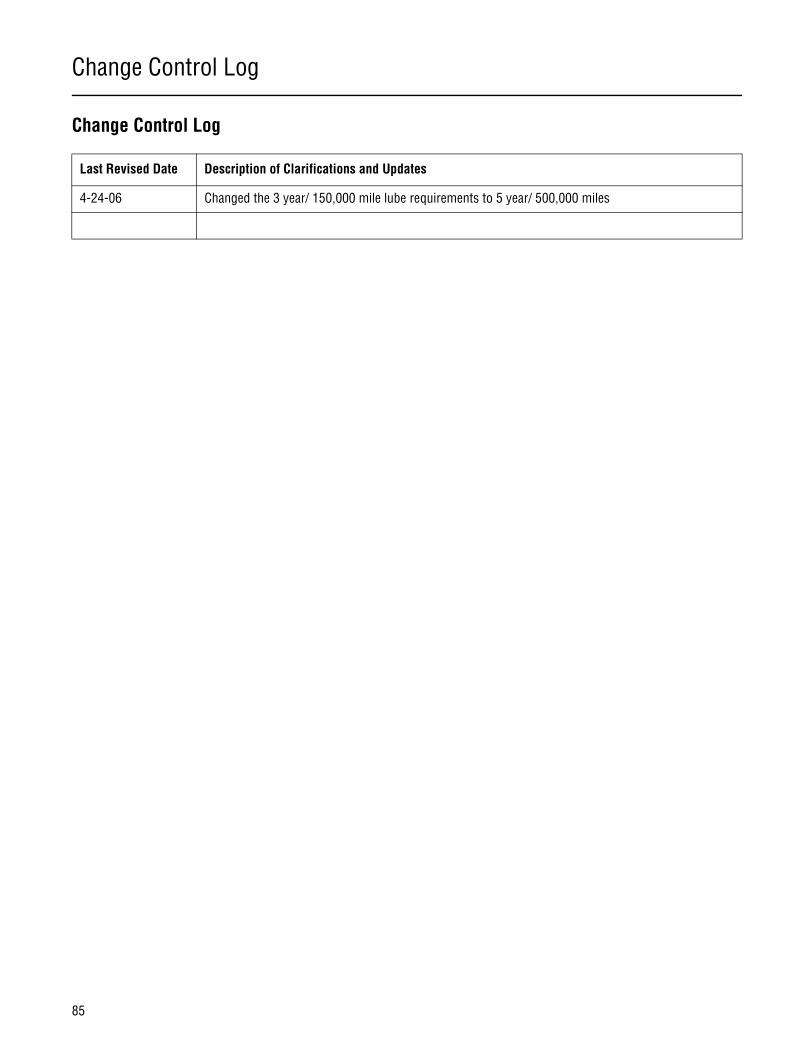
Change Control Log
85
Change Control Log
Last Revised Date Description of Clarifications and Updates
4-24-06 Changed the 3 year/ 150,000 mile lube requirements to 5 year/ 500,000 miles

This page intentionally left blank.

Copyright Eaton Corporation, 2012. Eaton hereby grant their customers, vendors, or distributors permission to freely copy, reproduce and/or distribute this document in printed format. It may be copied only in its entirety without any changes or modifications. THIS INFORMATION IS NOT INTENDED FOR SALE OR RESALE, AND THIS NOTICE MUST REMAIN ON ALL COPIES.
Note: Features and specifications listed in this document are subject to change without notice and represent the maximum capabilities of the software and products with all options installed. Although every attempt has been made to ensure the accuracy of information contained within, Eaton makes no representation about the completeness, correctness or accuracy and assumes no responsibility for any errors or omissions. Features and functionality may vary depending on selected options.
For spec’ing or service assistance, call 1-800-826-HELP (4357) or visit www.eaton.com/roadranger.In Mexico, call 001-800-826-4357.
Eaton CorporationVehicle GroupP.O. Box 4013Kalamazoo, MI 49003 USA800-826-HELP (4357)www.eaton.com/roadranger
Printed in USA
Roadranger: Eaton and trusted partners providing the best products and services in the industry, ensuring more time on the road.