Embed Size (px)
Citation preview
01
Full Transparency with Automotive Ethernet
Finally seeing what is really happeningAutomotive Ethernet – in contrast to CAN, LIN and FlexRay – is not simply another bus that sparkles with very high transmission rates. Rather development and testing departments are confronted with an entirely different network topology, which in many aspects requires a different approach to thinking and acting. This article describes, based on the example of a new flexible Automotive Ethernet interface, the specific challenges that developers face. It also demon-strates the ideal way to structure hardware and software and have them interact to achieve optimal development, sim-ulation and test results under the new constraints.
Open Alliance BroadR-Reach), high-speed networks can be implemented easily and cost-effectively based on a single, unshielded twisted pair cable (UTP). The system is capable of transmitting a gross data rate of 100 MBit/s simultane-ously in each direction. Based on the full-duplex method, it can therefore achieve an overall rate of 200 Mbit/s.
Network of 1-to-1 Connections and Switches Instead of Bus SystemHowever, this large bandwidth advantage comes at the cost of a paradigm shift for the automotive industry, because Automotive Ethernet differs significantly from the
The central appeal of Ethernet in the automotive industry is that it offers tremendous gains in bandwidth, which is playing an increasingly more important role in current and future applications. Systems for autonomous driving and Advanced Driver Assistance Systems (ADAS) are always in need of most current data about the surroundings from cameras and radar systems. There, and in other areas, high transmission rates are needed, e.g. to quickly transmit video streams and sensor data. But the time and cost advantages of a high bandwidth are even welcome in such tasks as flashing large numbers of ECUs. Using the IEEE standard for Automotive Ethernet, 100BASE-T1 (OABR,
02
Technical Article / April 2016
topology of bus systems such as CAN, LIN and FlexRay. There are no bus conductors to which numerous ECUs, sen-sors and actuators are jointly connected. Instead, it is a network of switches and many electrical point-to-point connections. In such fully switched networks, the topology – i.e. the layout of individual nodes – plays an important role, especially when it comes to real-time capability. Tech-nologies such as AVB (Audio Video Bridging) and TSN (Time Sensitive Networking) have implications for switches and ECUs, and in the future they will enrich Automotive Ether-net networks with functions such as prioritization of data packets and time synchronism.
All of this noticeably increases complexity and has effects on development, testing and simulation of the related net-works. Convenient network access by test and simulation tools has always been an important aspect of the develop-ment process, and Automotive Ethernet is no exception. However, switched networks lack “the one bus” on which all signals and messages can be accessed or test messages can be sent out. This leads to the question: What capabili-ties and properties does an interface hardware device need to offer to meet current and future requirements?
Measurement With no Effect on The Network is Practi-cally ImpossibleThe basic requirements of an interface for Automotive Ethernet do not really differ from those for other commu-nication systems: with a rugged housing, reliable plug con-nectors designed for many plug-in cycles and an extended temperature range, the hardware is equally well-suited for the laboratory and for outdoor in-vehicle applications. The software tools require extensive network access, which means that the interface needs to be able to handle both passive read accesses and active write accesses. Important for all of these activities, of course, are highly precise time stamps and the ability to synchronize with other interfaces and other bus systems in multibus environments. The hard-ware communicates with the simulation or analysis tools via a stable and high-performance host interface.
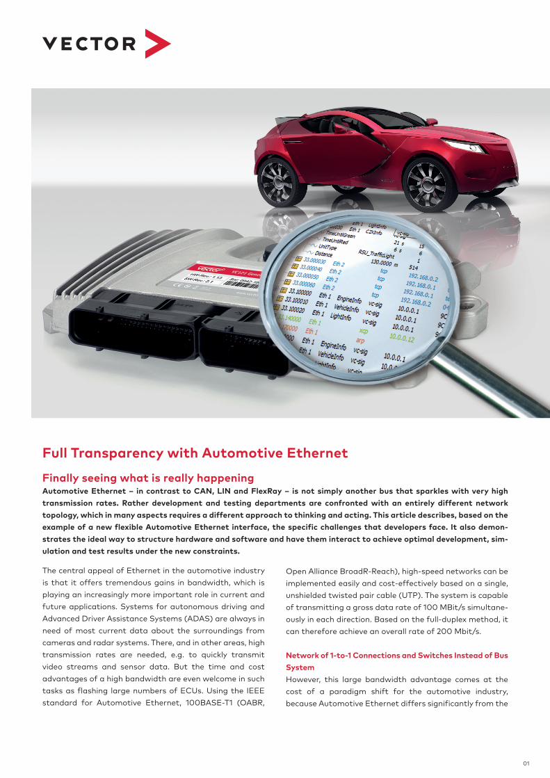
As mentioned, a switched Ethernet network consists of many 1-to-1 connections (Figure 1) whose full-duplex trans-mission makes access without effect on the network nearly impossible. Even tapping the data signal at the network cable between two switches or ECUs with an ideal, high- impedance measurement system to passively listen to data traffic is of little use, because the tapped signals can-not be decoded. Only the counterpart ECU at the other end of the transmission line can decode the received informa-tion by differentially comparing it with its own signal from the signal mix.
In practice, there is no alternative to splitting a 1-to-1 con-nection of interest and inserting additional hardware such as a TAP (Test Access Point) (Figure 2). A TAP provides two Ethernet ports and a connection to the computer with the analysis tools that can distinguish the different operating modes of a TAP. For pure monitoring, passive TAPs are suf-ficient, which loop through the data on ISO-OSI Layer 1, i.e. the physical level. In this process, the TAP is essentially transparent with regard to key communication properties. Errors in transmitting Ethernet packets are passed and not rejected. To achieve time synchronization in the network, it is important to keep the unavoidable pass-through delay constant and minimal. However, as soon as one wishes to intervene in events and modify data, active TAPs are need-ed. Comparable to a switch, they operate on the Data Link Layer (Layer 2).
Functional Development vs. Network ViewIn pure functional development, a TAP is often sufficient, because here the focus is generally on an individual connec-tion between two network nodes, e.g. from ECU-to-ECU or ECU-to-switch. Along with purely passive listening to indi-vidual connections, the software tools also perform tasks such as the remaining bus simulation and inserting addi-tional data packets and disturbances. The situation
Figure 1: Example of a switched Ethernet network that consists of multiple 1-to-1 connections.
Figure 2: A typical measurement setup in which signals are acces-sed by splitting the 1-to-1 connections and looping them through interfaces. A common time base must be provided for precise ana-lysis.
03
Technical Article / April 2016
neously, they have to insert their interfaces at multiple points. If the latter are discrete devices, a synchronization mechanism is needed now at the latest, so that all inter-faces are operating to the same time base and the tests can produce usable results.
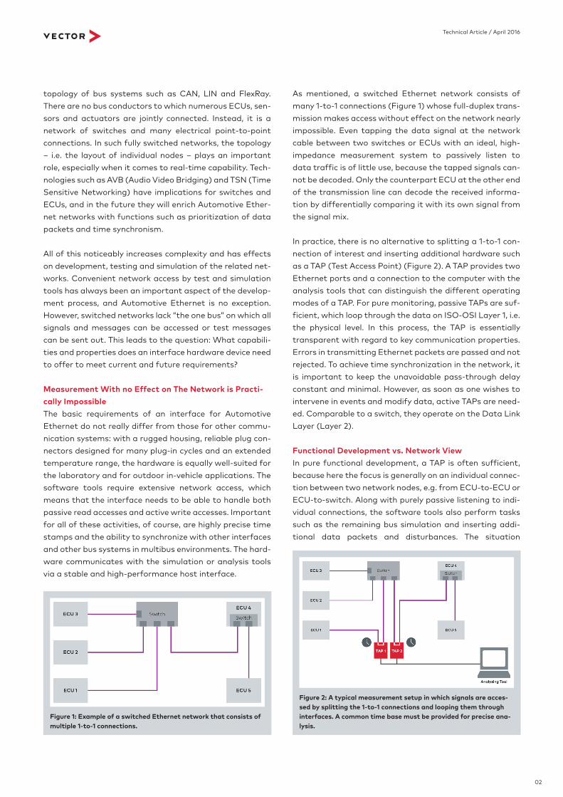
In addition to network access, the topology also represents a challenge in switched networks. An example from prac-tice illustrates the fundamental problem in testing an indi-vidual ECU: The real device under test is connected, via an Automotive Ethernet interface, to the test computer on which two virtual ECUs run for the remaining bus simula-tion. Usually the PC with the simulation tools has exactly one TCP/IP stack, so that the two virtual ECUs can com-municate externally to the interface via the common stack. The data traffic generated by the PC does not by any means represent a real situation. That is because the ECU under test cannot distinguish the messages of the two simulated ECUs, since they act under the same IP-address and MAC-address. Conversely, the ECU under test is not able to address the virtual ECUs separately. It would be
becomes difficult when analyzing Automotive Ethernet scenarios that are more complex, in which developers need an overview of the entire system (Figure 3). Then the attention is on entire data paths. In addition to total trans-mission times and pass-through times in the switches, users are interested in detailed information about rejected messages and MAC address tables, for example. If users need to perform multiple accesses to the network simulta-
Figure 3: Data transmission from ECU 1 to ECU 5 via three connec-tions and two switches.
Figure 4: Remaining bus simulation with multiple TCP/IP stacks. In the framework of integration, the simu-lated ECU 2 is replaced by a real ECU under consideration of the topology.
04
Technical Article / April 2016
just the number of ports that is crucial here, as has already been shown above. It is important to understand that – up to now – simply shifting a device between simulation and the real world was equivalent to a change in topology. If users are only equipped with conventional standard com-ponents and tools, such seemingly simple work steps can pose enormous challenges. Given this situation, what are the key properties of a powerful Automotive Ethernet interface that is suitable for the future? Ideally, an inter-face decouples the simulation from the direct Ethernet ports by inserting what is known as an application channel between them on the PC side. Moreover, it fills the gap between the application channel and the 100BASE-T1 ports with a user-configurable transfer function (Figure 4). A typical and frequently needed transfer function is the switch functionality.
The use of an FPGA makes it easy to implement further extionsions for new transfer functions, which can be select-ed and configured appropriately. The interface is therefore extremely flexible to adapt it to the practical challenges of different development and test phases. Furthermore, nearly every network configuration and topology can be mapped to a functionally identical test setup. If necessary, the user can configure multiple parallel application chan-nels as well as transfer functions and connect them to the Ethernet ports. In addition to switches, transfer functions come into consideration, which include “PHY Bypass” (mapping on Layer 1) and “MAC Bypass” (store-and- forward principle on Layer 2) functions. The interface also allows the tools full access to the Ethernet ports at all times, either direct or relative, over the application channel. Native access to Ethernet frames at the bus transceiver
necessary to specially modify the ECU just to be able to perform testing – which is a highly inefficient working method.
Shifting Complexity to Software and Hardware ToolsThis situation can be remedied by a specialized tool that makes it possible to place a special TCP/IP stack instance after each simulated ECU (Figure 4). Together with the interface hardware, the user can then stimulate the real ECU so that the simulated communication matches the real communication. Over further course of testing, a col-league might erroneously come up with the idea – one that is familiar from CAN – of “just removing” one of the simu-lated ECUs from the simulation and replacing it by its real counterpart. When the user connect it to an available Eth-ernet port on the interface, would it work? Unfortunately, this approach ignores the fact that Ethernet networks only permit 1-to-1 connections. A 1-to-1 connection exists in the test layout, but it is already between the real ECU and the software with the remaining simulated ECU. In practice, other devices can only be added by establishing new, addi-tional 1-to-1 connections, whereby the new network frag-ments need to be coupled to the existing network via switches. If the interface offers switch functionality inter-nally or could be reconfigured to do so, the colleagues might successfully implement their plan and connect the second external ECU to an available port.
The Interface is More Than the Sum of its Ethernet PortsTo adequately meet user requirements, a high-perfor-mance Automotive Ethernet interface is equipped with numerous ports. Twelve 100BASE-T1 ports are sufficient to implement relatively complex test scenarios. But it is not
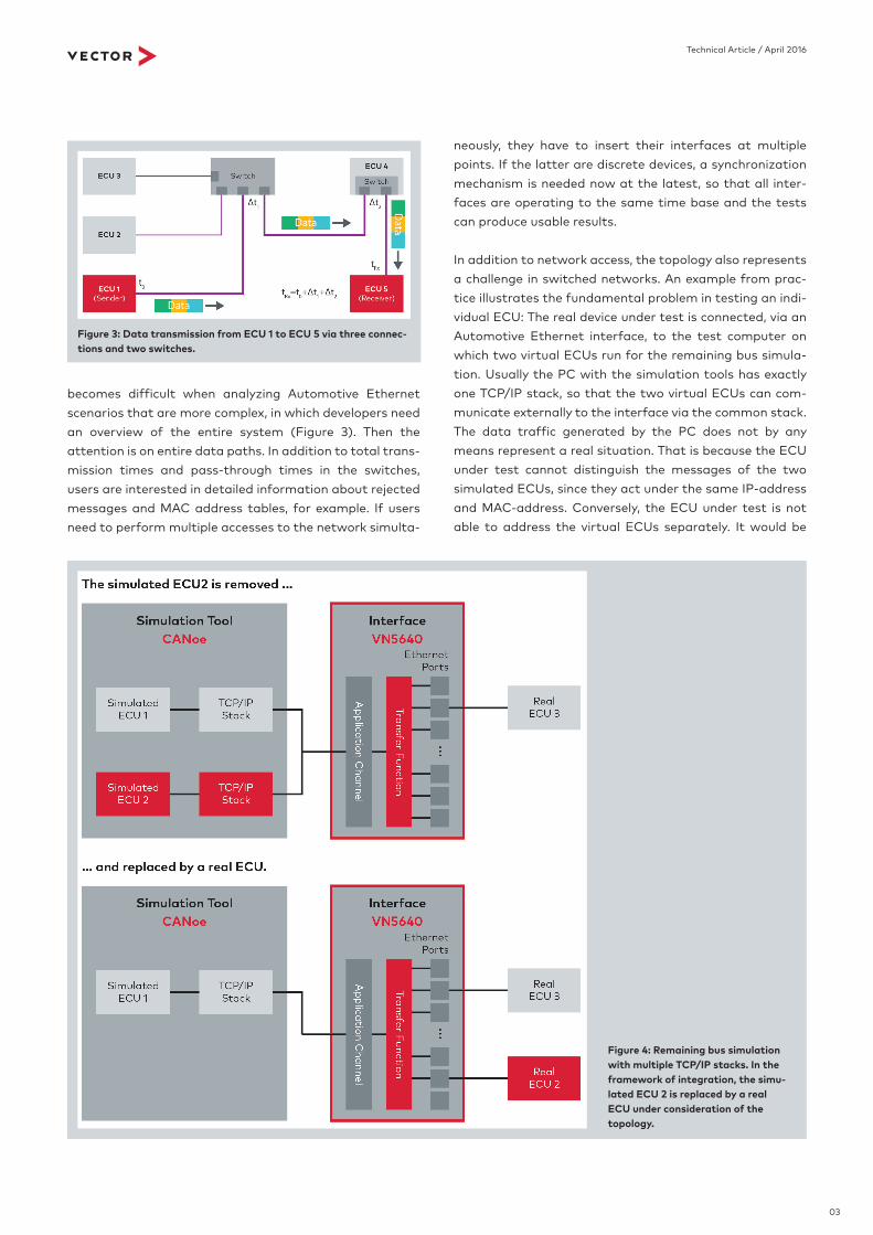
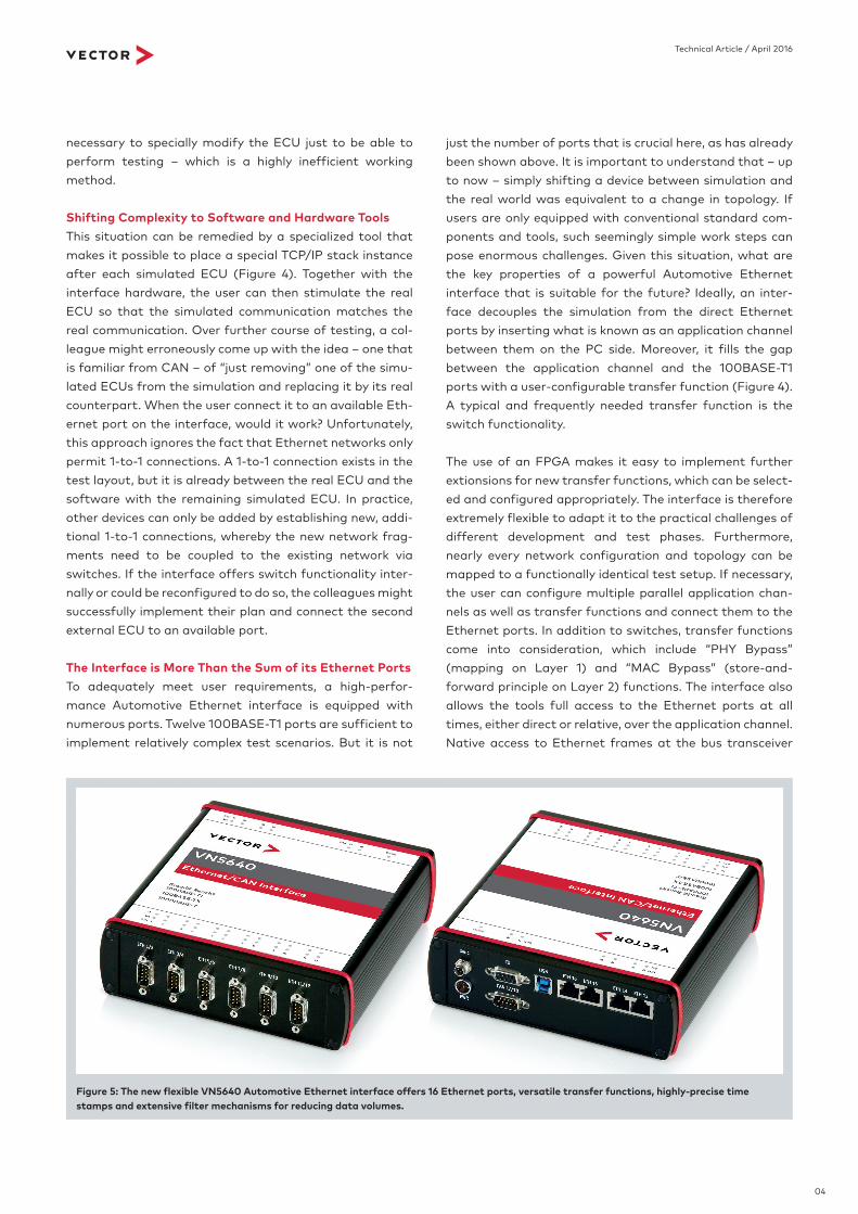
Figure 5: The new flexible VN5640 Automotive Ethernet interface offers 16 Ethernet ports, versatile transfer functions, highly-precise time stamps and extensive filter mechanisms for reducing data volumes.
05
Technical Article / April 2016
interface hardware specially tailored to meet these new challenges offers valuable support. In combination with test and simulation tools that have been tuned for the new requirements, this interface hardware will sustainably sim-plify and accelerate development and test processes.
To meet the growing demand for bandwidth, IEEE is already working on a 1-GBit variant of 1000BASE-T1. Due to the flexibility in hardware setup the VN5640 interface is prepared for other physical layers and can be available quickly. Technologies such as AVB (Audio Video Bridging) and TSN (Time Sensitive Networking) will, in the foresee-able future, provide for guaranteed worst-case latencies, prioritized data transmissions and time synchronism. As they become available, these and other advanced develop-ments will also be implemented in firmware and software updates so that users will always be able to work with Automotive Ethernet interfaces from Vector Informatik that represent state-of-the-art technology.
during monitoring can reveal problems on the bus such as corrupt frames, which are filtered out by the MAC layer in conventional switches. This enables meaningful analyses that yield findings on what is happening directly on the bus and what is arriving at the ECU.
Scalable Line of Interfaces for Challenging Automotive Ethernet ApplicationsVector Informatik has integrated all of the named func-tions and further functions into its new Automotive Ether-net Interface VN5640 (Figure 5). The device was specially designed for the application area of simulating or measur-ing on the network view level, and it has a total of 16 Ether-net ports: twelve for IEEE 100BASE-T1 and four for stan-dard Ethernet connections such as 100BASE-TX or 1000BASE-T. A very fast host connection routes the enor-mous quantities of data that can arrive at the Ethernet ports. Since generally just a subset of the Ethernet frames is relevant for typical test and simulation tasks, the VN5640 hardware provides many filter mechanisms that can be activated. Based on the various protocols, the filters only pass the really necessary Ethernet frames to the PC and thereby make a significant contribution toward relieving loads in the simulation and test software.
Along with the usual interface mode, the VN5640 can also be used in stand-alone mode without a PC. In addition, there are future plans for letting the user connect an Eth-ernet-capable standard automotive data logger. Together with the VN5610 2-port interface, which has already been available for some time now, the VN5640 represents a scalable Automotive Ethernet interface family that works perfectly with the widely used CANoe test and simulation tool from Vector. In the future, many new functions of the VN5640 will also be supported by the VN5610 and be avail-able after a driver update. All interfaces in this product line can be addressed over a common programming interface (API). In combination with CANoe, users can use descrip-tion files to conveniently exploit the extensive configuration options. This also offers the advantage of sharing the files with other departments, suppliers and customers. Further-more, CANoe offers access to extended statistical and switch information – such as quality information about transmission paths, the contents of MAC address tables and the queue states of switches – which provide useful insights regarding the loads of individual link segments.
Conclusion and OutlookThe proper methods for developing, testing and simulating Automotive Ethernet networks are generally more difficult than users are accustomed to with CAN, LIN and FlexRay, and the tasks require a differentiated approach. Modern
Peter Fellmeth (Dipl.-Ing. (FH)) is a group leader and product manager at Vector Informatik GmbH. He is responsible for the development of products for Automotive Ethernet, J1939 and ISOBUS.
Translation of a German publication in Elektronik automo-tive Ethernet edition April 2016
Image rights: Vector Informatik GmbH
Matthias Schwedt (Dipl.-Ing. (FH))is a product manager for network interfaces at Vector Informa-tik GmbH. In this position he is responsible for the VN5600 Au-tomotive Ethernet interface family.