Embed Size (px)
Citation preview
Research ArticleFull-Scale Testing of Precast Concrete Bridge Using InternalConnector in Negative Moment Region
Heeyoung Lee ,1,2 Junki Min,3 and Wonseok Chung 4
1Post-doctoral Research Associate, Kyung Hee University, Yongin-Si, Republic of Korea2Post-doctoral Research Associate, University of California, San Diego, USA3Graduate Student, Kyung Hee University, Yongin-Si, Republic of Korea4Professor, Department of Civil Engineering, College of Engineering, Kyung Hee University, 1732 Deokyoung-Daero, Giheung-Gu,Yongin-Si, Gyeonggi-Do 17104, Republic of Korea
Correspondence should be addressed to Wonseok Chung; [email protected]
Received 19 March 2019; Revised 31 May 2019; Accepted 10 July 2019; Published 4 August 2019
Academic Editor: M. Shahria Alam
Copyright © 2019Heeyoung Lee et al.*is is an open access article distributed under the Creative Commons Attribution License,which permits unrestricted use, distribution, and reproduction in any medium, provided the original work is properly cited.
Conventional concrete marine structures are difficult to construct on site and can cause pollution of the environment. *erefore,concrete marine structures require the development of methods that can minimize the amount of construction that needs to beperformed in the field. *is study aims at facilitating assembly through the use of precast girders and precast bent cap and atimproving construction efficiency by minimizing cast-in-place structures. *e proposed bridge can reduce the negative momentof the girder through continuous connection. In this study, a full-scale connection specimen with a 10.0m span was fabricated,and the behavior of the precast connection was evaluated by performing a negative moment performance test. In addition, a finiteelement model was developed to compare each loading step with the test results. *e failure mode of the specimen was that thereinforcing bars yielded at the joint of the cast-in-place section and the precast girder. As a result of the study, this proposed bridgeis easy to construct because it minimizes the process of connecting the coping and girders using the internal connector. Also, theproposed bridge has 155% higher structural performance than the designed load at the negative moment connection part.
1. Introduction
Existing marine structures have faced problems such as deckdamage and steel corrosion. Such problems decrease du-rability and structural stability and require cyclic mainte-nance of the structures. Given that cast-in-place concretestructures require the use of temporary facilities, this maycause difficulties in construction and damage to the marineenvironment. Precast concrete structures require connectionof separate brackets to secure the composite performance atthe joints between steel pipes and precast bent caps. As such,it is essential to improve techniques for the construction ofbridges that are suitable for the marine environment and canreduce cost and construction period by minimizing on-siteconstruction.
Many studies have been performed on marine structures[1–10]. Soares et al. [11] modeled the effects of relative
humidity, chloride, and temperature on the corrosion be-havior of steel structures exposed to the marine atmosphere.*is study proposed a precise equation for prediction ofpollution in marine conditions, and the proposed modelprovided more accurate predictions of corrosion behaviorthan existing models by adding constraints from experi-mental results. Zhang et al. [12] published a study on thecorrosion resistance and bonding of geopolymers withhardened cement.*e study documented themicrostructureand pore structure of geopolymers using a number of an-alytical techniques. It verified that the microstructure ofgeopolymers contributed to the resistance to seawater dif-fusion and bonding with cement, making geopolymers apotential coating material for marine concrete structures.Garcia-Espinel et al. [13] investigated a marine bridge underthe seawater. *is study investigated the effect of seawaterenvironment on the mechanical characteristics of various
HindawiAdvances in Civil EngineeringVolume 2019, Article ID 6309859, 12 pageshttps://doi.org/10.1155/2019/6309859

factors. *is study determined the safety factor used in thestructural calculation design of marine applications. Bradneret al. [14] tested a series of 1 : 5 scale reinforced concretebridge upper structures to determine the effect of wave forceon coastal highway bridges. *e test system set the stiffnessof the horizontal support system to characterize dynamicbehaviors and presented data that show the close link be-tween the wave height and load.
Precast concrete structures can upgrade constructionperformance in the field, but it is necessary to confirm theirstructural performance. Numerous studies on precastconcrete structures have been performed to date throughexperimental testing and FE analysis. Caner and Zia ex-amined an experimental structural study on link slabs usinga full-scale specimen [15]. A two-span full-scale steel-con-crete composite bridge was fabricated. *e behavioralcharacteristics of bridges were investigated at diverseboundary conditions. de la Fuente et al. [16] studied anoptimized cross section using a numerical model for eachprecast concrete bridge construction order. Baskar et al. [17]conducted a nonlinear analysis of data from fracture tests ofsteel and concrete composite plate girders to determine theexpected structural behavior of composite plate girdersunder ultimate loads. Issa and Abdalla [18] studied epoxy-jointed single keys in precast concrete structures. Severalspecimens were fabricated to verify the shear performanceand evaluate the effect of temperature on the shear strengthof epoxy. *e experimental results demonstrated that thefailure mode of the specimen was a concrete fracture due toshear force. It was confirmed that the shear strength of theepoxy specimen improved at higher temperatures. Lee et al.[19] examined the composite behavior of an inverted T-bentcap-girder integral steel bridge through a nonlinear FEanalysis. *is study confirmed the validity of the proposedbridge by predicting its overall composite behavior andcomparing the results with those of a test with a full-scalemodel. Ko et al. [20] studied the composite behavior of thenew bent cap joint to ensure proper structural performance.In this study, the connecting steel girders and bent caps weresubjected to a two-million-cycle fatigue test. Marı andValdes [21] studied a continuous bridge constructed ofprecast concrete beams with U-shaped cross section using a1 : 2 scale model to determine its behavior under permanentload. *is study analyzed deflection and strain for 500 daysand compared them with the results of a nonlinear and time-dependent analysis of prestressed and reinforced concretestructures. Shah et al. [22] tested irregular bolted connec-tions between flanges for continuous precast bulb-T girders.*e factors influencing the failure mode of the model andthe load capacity of the connection were analyzed.
*is study proposes an internal connector that facilitatesthe connection of steel pier and precast concrete bent caps.*e proposed bridge can be constructed with minimumequipment and does not require separate bracket in-stallation. In this study, a full-scale bridge composed ofprecast girders and precast bent caps including internalconnectors is fabricated, and the composite behavior of theconnection is studied. A full-scale specimen of the con-nection between a precast bent cap combined with a steel
pier and a precast girder was fabricated. A loading test wasalso performed so that negative moment could be created atthe connection of the full-scale specimen and the behavior ofthe connection at each loading step was analyzed. *eloading test of the connection was conducted based on thedesign load considering the marine characteristics [23, 24].In the test, the crack pattern and final failure mode of the testbridge were investigated. Furthermore, the behavior ofreinforcing bars and concrete at the key locations of the testunit was examined to confirm their composite behavior.*isstudy develops a three-dimensional (3D) finite elementmodel and verifies its validity by comparing the behavior ineach loading step with the test results.
2. Proposed Precast Bridge
Cast-in-place concrete bent caps for marine structures maycause environmental problem and require temporaryequipment and facilities for the formwork system. Since theproposed bridge is made of precast girder and bent cap,uniform strength can be obtained. Additionally, precastconcrete bent caps involve difficult construction techniquesin which separate external brackets must be installed forconnection with steel piles. In this study, precast girders andprecast bent caps with internal connectors, which aresuitable for the marine environment, are proposed to im-prove joint performance and construction efficiency.
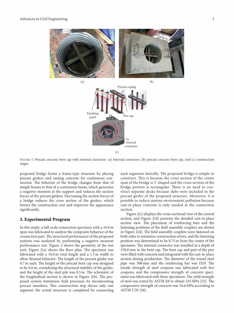
Figure 1 illustrates the proposed bridge. *is proposedconnection system provides internal connectors betweensteel piers and precast bent caps. *e internal connection isinstalled in a circular steel pier in the shape of a cross asshown in Figure 1(a). Figure 1(b) shows precast concretebent cap with an internal connector. After the constructionof the steel pier, the precast concrete coping is installed onthe pier, as shown in Figure 1(c). When the precast bent capis installed on the top of a circular steel pier, the internalconnection supports the bent cap and can be easily placed.Bent caps, concrete girders, and part of the pier are filled bycasting concrete in the field. *e internal connection systemis installed between a steel pier and precast coping. *eupper part of the pier is filled with concrete to integrate thecoping. A finishing panel is installed in the pier to control thefilling depth of the concrete in the pier. After the insertion ofthe finishing panel, the pier cap is fixed to the top of the pierand facilitates the placement of the precast coping. *einternal connectors are readily installed in the precastconcrete bent caps in order to protect the composite be-havior with steel piles. *e internal connectors of the precastbent caps can improve appearance and eco-friendlinessbecause no separate temporary equipment is used for theinstallation of the external brackets in the field.
Structurally, the proposed bridge systems minimize thecross section because of continuous sections at the supportsof the existing precast concrete bridge. In the case of thesimple placement of precast girders on precast bent caps, thestructure behaves like simple beams. In simple bridges, alarge positive moment is created at the center of the span,which increases the cross-section of the girder and thusinvolves higher construction and maintenance costs. *e
2 Advances in Civil Engineering
proposed bridge forms a frame-type structure by placingprecast girders and casting concrete for continuous con-nection. *e behavior of the bridge changes from that ofsimple beams to that of a continuous beam, which generatesa negative moment at the support and reduces the sectionforces of the precast girders. Decreasing the section forces ofa bridge reduces the cross section of the girders, whichlowers the construction cost and improves the appearancesignificantly.
3. Experimental Program
In this study, a full-scale connection specimen with a 10.0mspan was fabricated to analyze the composite behavior of theconnection part.*e structural performance of the proposedsystems was analyzed by performing a negative momentperformance test. Figure 2 shows the geometry of the testunit. Figure 2(a) shows the floor plan. *e specimen wasfabricated with a 10.0m total length and a 1.5m width toallow flexural behavior. *e length of the precast girder was4.7m each. *e height of the precast bent cap was designedto be 0.6m, considering the structural stability of the girder,and the height of the steel pile was 0.5m. *e schematic ofthe longitudinal section is shown in Figure 2(b). *e pro-posed system minimizes field processes by incorporatingprecast members. *is construction step shows only onesegment; the actual structure is completed by connecting
such segments laterally. *e proposed bridge is simple toconstruct. *is is because the cross section of the centerspan of the bridge is T-shaped and the cross section of thebridge portion is rectangular. *ere is no need to con-struct separate decks because slabs were included in theprecast girder of the proposed structure. Moreover, it ispossible to reduce marine environment pollution becausecast-in-place concrete is only needed at the connectionsection.
Figure 2(c) displays the cross-sectional view of the centralsection, and Figure 2(d) presents the detailed cast-in-placesection view. *e placement of reinforcing bars and thefastening positions of the field assembly couplers are shownin Figure 2(d). *e field assembly couplers were fastened onboth sides to minimize construction errors, and the fasteningposition was determined to be 0.75m from the center of thespecimen. *e internal connector was installed at a depth of150.0mm in the bent cap. *e bent cap and part of the pierwere filled with concrete and integrated with the cast-in-placesection during production. *e diameter of the round steelpipe was 508mm and the reinforcing bar was D29. *etensile strength of steel coupons was fabricated with fivecoupons, and the compressive strength of concrete speci-mens was fabricated with three specimens.*e yield strengthof steel was tested by ASTM E8 to obtain 235MPa [25]. *ecompressive strength of concrete was 34.6MPa according toASTM C39 [26].
(a) (b)
Precast coping
Pier capFinishing
panel
Internalconnector
(c)
Figure 1: Precast concrete bent cap with internal connector. (a) Internal connector, (b) precast concrete bent cap, and (c) constructionstages.
Advances in Civil Engineering 3

4,700 600 4,70010,000
1,50
0
(a)
150
10,000
4,400
1,60
0
4,700
1,200
600
4,400
500
350
4,700
600
10,000
600
(b)
150
600
1,500
1,60
0
500
350
(c)2,200
1,50
0
JS2
H29
H13
JS1
J2
H13
H13
J1
(d)
Figure 2: Geometry of test unit. (a) Floor plan, (b) longitudinal section, (c) cross-sectional view, and (d) cast-in-place section view.
4 Advances in Civil Engineering

*e specimen fabrication procedures are shown in Fig-ure 3. In this study, the full-scale specimen was turned upsidedown. A full-scale test unit is heavy, so there is a problem insetting up the test specimens after completing the test speci-mens. *erefore, the upside-down specimen was fabricated,and a three-point static loading test was performed. As shownin Figure 3(a), the precast girders and bent cap were factory-made. *e precast bent cap with the internal connector wasfabricated, as shown in Figure 3(b). At this time, steel straingauges were installed on the reinforcing bars embedded in theprecast girders and precast bent cap. Figure 3(c) shows thefabricated steel pile with a bracket installed. After curing theprecast girders, the field assembly couplers between the girderswere fastened, as shown in Figure 3(d). *e precast concretebent cap and steel pier were placed on the connected precastgirders, as shown in Figure 3(e). Figure 3(f) shows the concretecast into the steel pile to fill the cast-in-place section, the bentcap, and the inside of the pile. When casting concrete in theconnection part, one side of the formwork was made of acrylicto confirm that the cast-in-place section was filled with con-crete without any voids.
Figure 4 displays the installed specimen. In the case ofthe normal direction, two actuators are required. However, itis not possible to use two actuators at the same time withouterror. *erefore, as mentioned earlier, upside-down speci-mens were prepared, and the three-point static loading testwas performed. Figure 4(a) illustrates the displacementtransducer and strain gauges installed on the specimen. *edisplacement transducer was installed at the center of thespecimen to measure the deflection of the specimen due toan increase in load. A 200mm displacement transducer wasused, and the strain gauges were installed on the concreteand the reinforcing bars of cross-sections. *e crack gaugeswere set up at the joint of the cast-in-place section and thegirders to examine the point of crack formation and thenumber of cracks. Figure 4(b) shows the installation of thespecimen. Actuators with a 2,000 kN capacity were used forloading. *e test was performed at a 0.02mm/s loading rateusing the displacement control method. *e supports of thespecimen were set to a 7.0m span, and enough overheadclearance was obtained for displacement measurements. *esupports were installed at the actual loading positions. *esupports were installed at the actual loading positions. *edesign load was converted to the load obtained by sub-tracting the moment owing to the weight from the normalbending moment [27]. *e design load moment (M) iscalculated as shown in equation (1). ∅Mn is the nominalmoment and Md is the self-weigh moment. *e concen-trated load used in the experiment was calculated by dividingthe design load moment by the length, as given in equation(2).*e calculation results indicated that the cross-section ofthe specimen reached the design strength when the load was448.0 kN in the test.
M � ∅Mn − Md, (1)
P �4M
L. (2)
*e cracking moment (Mcr) was calculated as inequation (3). *is experiment was set up in the upside-downdirection and the self-weight moment was excluded from thecracking moment, as given in equation (4). *e crack load isthen determined based on the cracking moment in test(Mcrt) as shown in equation (5).
Mcr �fr · Ig
yt, (3)
Mcrt � Mcr − Md, (4)
Pcr �4Mcrt
L, (5)
where Ig is the cross-sectional secondary moment, yt is thedistance from the center of the shape to the tension side, andfr is the modulus of rupture in crack.
4. Finite Element Analysis
In this study, finite element (FE) analysis was performed toverify the performance results of the connection where thenegative moment occurs. ABAQUS was used for the FEanalysis [28].*e dimensions of the FEmodel were the same asthose of the specimen. *at is, the total length was 10.0m andthe supports were simply supported at a 7.0m apart. 3D solidelements (C3D8R) were used for concrete members and steelpiers. *e couplers and the reinforcing bars were also modeledas solid elements placed in the same positions as in the testspecimen. *e connection system is modeled individually assolid elements. In the case of the coupler and internal con-nector, it is assumed that it is perfect bond composites, and thenode is shared with the concrete member. In addition, thecross-shaped inner support device and steel capwere combinedwith a steel pier using composite function (merge) within theABAQUS program. After completing the individual partmodeling, the element mesh is generated to minimize the errorof each node. *e results of the material test were used for thematerial properties of the concrete. *e FE analysis consideredthe nonlinearity of the materials using plasticity for the rein-forcing bars. Tables 1 and 2 present compressive properties andtensile properties of the concrete material, respectively. *eproposed FE model used a concrete damaged plasticity modelby ABAQUS programs to define the plasticity fields for thetensile and compressive behavior of the concrete [29–32]. *econcrete damaged plasticity FE model supplies a wide-rangingcapability for concrete cracking modeling and other quasi-brittle materials. It uses theories of isotropic damaged elasticityin combination with isotropic tensile and compressive plas-ticity to characterize the inelastic behavior of concrete. Materialmodel in this study involves with the combination of non-associated multihardening plasticity and isotropic damagedelasticity to define the irreparable damage that occurs duringthe fracturing process. *e elasticity modulus of the concretewas 27537MPa and Poisson’s ratio of the concrete was 0.18.*e modulus of elasticity and Poisson’s ratio of the steelmaterial were 200,000MPa and 0.3, respectively. Figure 5(a)displays the FE model by member. Figure 5(b) shows the joint
Advances in Civil Engineering 5

setup of the FEmodel. In this study, the girders and the cast-in-place part were divided in the FE model because the cracks inthe joints were predicted as shown in Figure 5(b). After thisdisconnection, the upper girder connection part was connectedusing rigid links and both the lower girder and the cast-in-placepart were connected using spring elements.*e stiffness valuesof the spring elements were set with reference to a previousstudy of the concrete crack interface modeling [33–36].Figure 5(c) presents the loading position and boundaryconditions.
5. Experimental and Numerical Results
*e displacement results analyzed the center of the speci-men. A FE analysis model for the same size as the testspecimen was used in this study for comparison with the
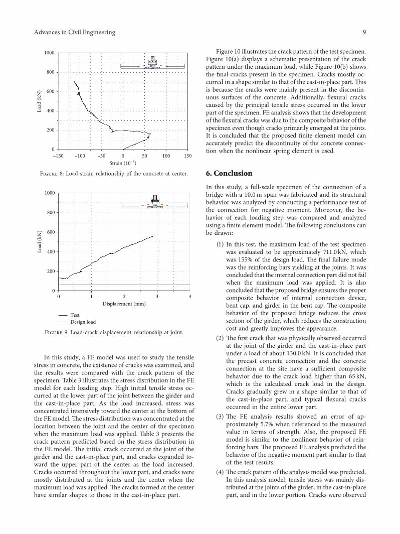
experimental results at each loading step. Figure 6 comparesthe load-displacement results at the center of the analysismodel with the experimental results. In the experimentalresults, nonlinear behavior associated with the initial crackin the concrete occurred at the joint of the cast-in-place partand the precast girder when about 130.0 kN was loaded. FEanalysis showed that the displacement increased moresteeply after approximately 178.0 kN as the cracks propa-gated. As the cracks in the concrete at the joints occurred, thetensile stresses mainly occurred in the reinforcing bars. *especimen failed at roughly 711.0 kN, and a displacement ofapproximately 70.0mm occurred. Experimental results in-dicate that all members were safe up to approximately 155%of the design load. *is tendency is due to the fact that theinternal connector in the coping, the bent caps, and thegirders have an appropriate composite behavior in the
(a) (b)
(c) (d)
(e) (f )
Figure 3: Fabrication procedures. (a) Fabrication of precast girders, (b) fabrication of precast bent cap, (c) fabrication of steel pier,(d) fastening the couplers, (e) placement of precast bent cap on girders, and (f) curing of concrete.
6 Advances in Civil Engineering

negative moment connection part. *e FE analysis resultsindicated that nonlinear behavior occurred at approximately133.0 kN due to cracks in the concrete. *e maximum loadof the FE analysis model was roughly 752.0 kN, indicating a5.7% error relative to the test results. It is also concluded thatthe proposed FE analysis predicted the behavior of thenegative moment part similar to that of the test results. *e
load-strain results of the reinforcing bars in the FE analysismodel are compared with the experimental results in Fig-ure 7. Initially, the strain of the reinforcing bars increasedlinearly, but nonlinear behavior resulted from the formedconcrete cracks at the joint. *e reinforcing bars yielded atthe maximum load of the specimen, and it is concluded thatthe final failure mode of the specimen was yielding of thereinforcing bars at the joint. It was also concluded that the
Crack gauge
7,00010,000
DisplacementTransducer
Concrete gaugeSteel gauge
(a)
(b)
Figure 4: Layout of test setup. (a) Sensor layout and (b) test setup.
Table 1: Compressive properties of concrete materials.
Compression hardening Compression damageStress (MPa) Inelastic strain Damage C Inelastic strain9 0 0 012.11868 4.48e − 5 0 4.48e − 518.0037 5.93e − 5 0 5.93e − 524.18227 9.25e − 5 0 9.25e − 530.00462 0.00046 0 0.0004624.14165 0.00154 0.1172412 0.0015312.14165 0.00341 0.3578292 0.003423.154534 0.00704 0.536919 0.00704
Table 2: Tensile properties of concrete materials.
Tension stiffening Tension damageStress (MPa) Inelastic strain Damage T Inelastic strain1.199358 0 0 01.7052 1.99e − 5 0 1.99e − 51.121886 9.62e − 5 0.24384 9.62e − 50.5176338 0.00017 0.41783 0.000170.1357524 0.00041 0.55223 0.000410.0339456 0.00065 0.58806 0.00065
Advances in Civil Engineering 7
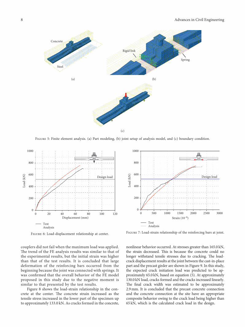
couplers did not fail when the maximum load was applied.*e trend of the FE analysis results was similar to that ofthe experimental results, but the initial strain was higherthan that of the test results. It is concluded that largedeformation of the reinforcing bars occurred from thebeginning because the joint was connected with springs. Itwas confirmed that the overall behavior of the FE modelproposed in this study due to the negative moment issimilar to that presented by the test results.
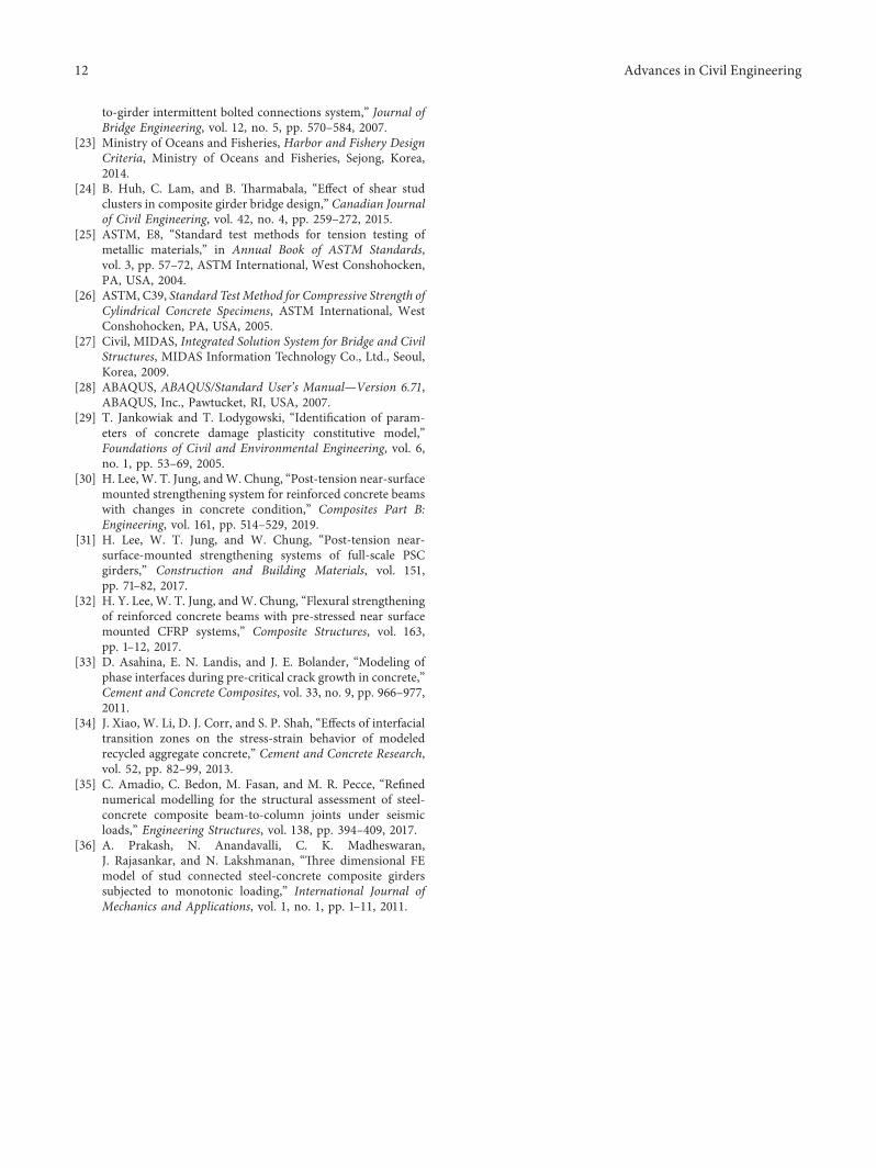
Figure 8 shows the load-strain relationship in the con-crete at the center. *e concrete strain increased as thetensile stress increased in the lower part of the specimen upto approximately 133.0 kN. As cracks formed in the concrete,
nonlinear behavior occurred. At stresses greater than 165.0 kN,the strain decreased. *is is because the concrete could nolonger withstand tensile stresses due to cracking. *e load-crack displacement results at the joint between the cast-in-placepart and the precast girder are shown in Figure 9. In this study,the expected crack initiation load was predicted to be ap-proximately 65.0 kN, based on equation (5). At approximately130.0 kN load, cracks formed and the cracks increased linearly.*e final crack width was estimated to be approximately2.9mm. It is concluded that the precast concrete connectionand the concrete connection at the site have an appropriatecomposite behavior owing to the crack load being higher than65kN, which is the calculated crack load in the design.
Steel
Concrete
(a)
Rigid link
Spring
(b)
(c)
Figure 5: Finite element analysis. (a) Part modeling, (b) joint setup of analysis model, and (c) boundary condition.
0 20 40 60 80 100 120
Design load
0
200
400
600
800
1000
Displacement (mm)
Load
(kN
)
TestAnalysis
Figure 6: Load-displacement relationship at center.
0 500 1000 1500 2000 2500 30000
200
400
600
800
1000
Strain (10–6)
Load
(kN
)
TestAnalysis
Design load
Figure 7: Load-strain relationship of the reinforcing bars at joint.
8 Advances in Civil Engineering
In this study, a FE model was used to study the tensilestress in concrete, the existence of cracks was examined, andthe results were compared with the crack pattern of thespecimen. Table 3 illustrates the stress distribution in the FEmodel for each loading step. High initial tensile stress oc-curred at the lower part of the joint between the girder andthe cast-in-place part. As the load increased, stress wasconcentrated intensively toward the center at the bottom ofthe FEmodel.*e stress distribution was concentrated at thelocation between the joint and the center of the specimenwhen the maximum load was applied. Table 3 presents thecrack pattern predicted based on the stress distribution inthe FE model. *e initial crack occurred at the joint of thegirder and the cast-in-place part, and cracks expanded to-ward the upper part of the center as the load increased.Cracks occurred throughout the lower part, and cracks weremostly distributed at the joints and the center when themaximum load was applied. *e cracks formed at the centerhave similar shapes to those in the cast-in-place part.
Figure 10 illustrates the crack pattern of the test specimen.Figure 10(a) displays a schematic presentation of the crackpattern under the maximum load, while Figure 10(b) showsthe final cracks present in the specimen. Cracks mostly oc-curred in a shape similar to that of the cast-in-place part. *isis because the cracks were mainly present in the discontin-uous surfaces of the concrete. Additionally, flexural crackscaused by the principal tensile stress occurred in the lowerpart of the specimen. FE analysis shows that the developmentof the flexural cracks was due to the composite behavior of thespecimen even though cracks primarily emerged at the joints.It is concluded that the proposed finite element model canaccurately predict the discontinuity of the concrete connec-tion when the nonlinear spring element is used.
6. Conclusion
In this study, a full-scale specimen of the connection of abridge with a 10.0m span was fabricated and its structuralbehavior was analyzed by conducting a performance test ofthe connection for negative moment. Moreover, the be-havior of each loading step was compared and analyzedusing a finite element model. *e following conclusions canbe drawn:
(1) In this test, the maximum load of the test specimenwas evaluated to be approximately 711.0 kN, whichwas 155% of the design load. *e final failure modewas the reinforcing bars yielding at the joints. It wasconcluded that the internal connection part did not failwhen the maximum load was applied. It is alsoconcluded that the proposed bridge ensures the propercomposite behavior of internal connection device,bent cap, and girder in the bent cap. *e compositebehavior of the proposed bridge reduces the crosssection of the girder, which reduces the constructioncost and greatly improves the appearance.
(2) *e first crack that was physically observed occurredat the joint of the girder and the cast-in-place partunder a load of about 130.0 kN. It is concluded thatthe precast concrete connection and the concreteconnection at the site have a sufficient compositebehavior due to the crack load higher than 65 kN,which is the calculated crack load in the design.Cracks gradually grew in a shape similar to that ofthe cast-in-place part, and typical flexural cracksoccurred in the entire lower part.
(3) *e FE analysis results showed an error of ap-proximately 5.7% when referenced to the measuredvalue in terms of strength. Also, the proposed FEmodel is similar to the nonlinear behavior of rein-forcing bars. *e proposed FE analysis predicted thebehavior of the negative moment part similar to thatof the test results.
(4) *e crack pattern of the analysis model was predicted.In this analysis model, tensile stress was mainly dis-tributed at the joints of the girder, in the cast-in-placepart, and in the lower portion. Cracks were observed
–150 –100 –50 0 50 100 1500
200
400
600
800
1000
Strain (10–6)
Load
(kN
)
Figure 8: Load-strain relationship of the concrete at center.
0 1 2 3 40
200
400
600
800
1000
Displacement (mm)
Load
(kN
)
TestDesign load
Figure 9: Load-crack displacement relationship at joint.
Advances in Civil Engineering 9

at the joints and throughout the lower part, and theproposed finite element model can predict the dis-continuity of the concrete connection similar to theactual behavior by using the nonlinear spring element.
Data Availability
*e data used to support the findings of this study are in-cluded within the article.
Table 3: Stress distribution and crack pattern from FE model.
Load step (kN) Stress distribution Crack pattern
200
S, max. principal(avg: 75%)
+3.421e + 00+3.037e + 00+2.654e + 00+2.271e + 00+1.887e + 00+1.504e + 00+1.121e + 00+7.376e – 01+3.543e – 01–2.899e – 02–4.123e – 01–7.956e – 01–1.179e + 00
300
S, max. principal(avg: 75%)
+3.491e + 00+3.081e + 00+2.671e + 00+2.262e + 00+1.852e + 00+1.442e + 00+1.032e + 00+6.221e – 00+2.122e – 00–1.976e – 01–6.075e – 01–1.017e + 00–1.427e + 00
500
S, max. principal(avg: 75%)
+3.887e + 00+3.374e + 00+2.860e + 00+2.346e + 00+1.833e + 00+1.319e + 00+8.055e – 01+2.918e – 01–2.218e – 01–7.354e – 01–1.249e + 00–1.763e + 00–2.276e + 00
Maximum load
S, max. principal(avg: 75%)
+4.002e + 00+3.346e + 00+2.690e + 00+2.034e + 00+1.378e + 00+7.218e – 01+6.567e – 02–5.904e – 01–1.247e + 00–1.903e + 00–2.559e + 00–3.215e + 00–3.871e + 00
(a) (b)
Figure 10: Crack pattern of the specimen. (a) Crack pattern under the maximum load and (b) final cracks.
10 Advances in Civil Engineering

Additional Points
(i) Construction of conventional concrete marine structureson site is difficult and can cause environmental pollution. (ii)A new bridge system is proposed to minimize the amount ofconstruction on site using precast structures. (iii) A full-scaleconnection specimen with a 10.0m span is fabricated andtested to investigate the composite behavior of the negativemoment region. (iv) A finite element model wasalso developed and verified against experimental results. (v)*e proposed bridge ensures the composite behavior andhas 155% higher capacity than the designed load at thenegative moment connection region.
Conflicts of Interest
*e authors declare that they have no conflicts of interest.
Acknowledgments
*is study is a basic research project conducted with supportfrom the National Research Foundation of Korea throughgovernment funds (Ministry of Science, ICT and FuturePlanning, South Korea). *e project numbers are2017R1A2B4010467 and 2017R1C1B1006732.
Supplementary Materials
Construction of conventional concrete marine structures onsite is difficult and can cause environmental pollution. A newbridge system is proposed to minimize the amount ofconstruction on-site using precast structures. A full-scaleconnection specimen with a 10.0m span is fabricated andtested to investigate the composite behavior of the negativemoment region. A finite element model was also developedand verified against experimental results. *e proposedbridge ensures the composite behavior and has 155% highercapacity than the designed load at the negative momentconnection region. (Supplementary Materials)
References
[1] S. D. Cramer, B. S. Covino Jr., S. J. Bullard et al., “Corrosionprevention and remediation strategies for reinforced concretecoastal bridges,” Cement and Concrete Composites, vol. 24,no. 1, pp. 101–117, 2002.
[2] M. G. Stewart and D. V. Rosowsky, “Time-dependent re-liability of deteriorating reinforced concrete bridge decks,”Structural Safety, vol. 20, no. 1, pp. 91–109, 1998.
[3] J. E. Padgett, A. Spiller, and C. Arnold, Statistical Analysis ofCoastal Bridge Vulnerability Based on Empirical Evidence fromHurricane Katrina, CRC Press, Boca Raton, FL, USA, 2012.
[4] K. A. T. Vu and M. G. Stewart, “Structural reliability ofconcrete bridges including improved chloride-induced cor-rosion models,” Structural Safety, vol. 22, no. 4, pp. 313–333,2000.
[5] C. Perea, J. Alcala, V. Yepes, F. Gonzalez-Vidosa, andA. Hospitaler, “Design of reinforced concrete bridge framesby heuristic optimization,” Advances in Engineering Software,vol. 39, no. 8, pp. 676–688, 2008.
[6] C. H. E. N. Zhaoyuan, “Durability design of concrete struc-tures,” Architecture Technology, vol. 5, 2003.
[7] C. Andrade, J. L. Sagrera, and M. A. Sanjuan, “Several yearsstudy on chloride ion penetration into concrete exposed toAtlantic Ocean water,” in Proceedings of the RILEM Proc. 19:2nd International Rilem Workshop on Testing and Modelingthe Chloride Ingress into Concrete, C. Andrade and J. Kropp,Eds., vol. 19, pp. 121–134, pp. 121–134, RILEM PublicationsSARL, Cachan, France, 2000.
[8] P. K. Mehta, Concrete in the Marine Environment, CRC Press,Boca Raton, FL, USA, 2002.
[9] M. B. Anoop and K. Balaji Rao, “Application of fuzzy sets forremaining life assessment of corrosion affected reinforcedconcrete bridge girders,” Journal of Performance of Con-structed Facilities, vol. 21, no. 2, pp. 166–171, 2007.
[10] J. R. Zhang and L. Wang, “Estimated approach to carryingcapacity of existing reinforced concrete bridge member,”China Journal of Highway and Transport, vol. 2, p. 8, 2006.
[11] C. G. Soares, Y. Garbatov, A. Zayed, and G. Wang, “Influenceof environmental factors on corrosion of ship structures inmarine atmosphere,” Corrosion Science, vol. 51, no. 9,pp. 2014–2026, 2009.
[12] Z. Zhang, X. Yao, and H. Zhu, “Potential application ofgeopolymers as protection coatings for marine concreteII.Microstructure and anticorrosion mechanism,” Applied ClayScience, vol. 49, no. 1-2, pp. 7–12, 2010.
[13] J. D. Garcia-Espinel, D. Castro-Fresno, P. Parbole Gayo, andF. Ballester-Muñoz, “Effects of sea water environment on glassfiber reinforced plastic materials used for marine civil engi-neering constructions,”Materials &Design, vol. 66, pp. 46–50,2015.
[14] C. Bradner, T. Schumacher, D. Cox, and C. Higgins, “Ex-perimental setup for a large-scale bridge superstructure modelsubjected to waves,” Journal of Waterway, Port, Coastal, andOcean Engineering, vol. 137, no. 1, pp. 3–11, 2010.
[15] A. Caner and P. Zia, “Behavior and design of link slabs forjointless bridge decks,” PCI Journal, vol. 43, no. 3, pp. 68–80,1998.
[16] A. de la Fuente, A. Aguado, C. Molins, and J. Armengou,“Numerical model for the analysis up to failure of precastconcrete sections,” Computers & Structures, vol. 106-107,pp. 105–114, 2012.
[17] K. Baskar, N. E. Shanmugam, and V. *evendran, “Finite-element analysis of steel–concrete composite plate girder,”Journal of Structural Engineering, vol. 128, no. 9, pp. 1158–1168, 2002.
[18] M. A. Issa and H. A. Abdalla, “Structural behavior of singlekey joints in precast concrete segmental bridges,” Journal ofBridge Engineering, vol. 12, no. 3, pp. 315–324, 2007.
[19] H. Lee, D. Cho, Z. An, andW. Chung, “Composite behavior ofsteel I-girders connected to inverted-T bent cap,” In-ternational Journal of Steel Structures, vol. 14, no. 4,pp. 711–721, 2014.
[20] Z. G. Ko, H. Lee, W. Bin, Z. An, and W. Chung, “An ex-perimental study on joint performance of steel I-girdersconnected to inverted-T bent cap in fatigue testing,” KSCEJournal of Civil Engineering, vol. 21, no. 7, pp. 2828–2836,2014.
[21] A. R. Marı andM. Valdes, “Long-term behavior of continuousprecast concrete girder bridge model,” Journal of BridgeEngineering, vol. 5, no. 1, pp. 22–30, 2000.
[22] B. N. Shah, K. Sennah, M. R. Kianoush, S. Tu, and C. Lam,“Experimental study on prefabricated concrete bridge girder-
Advances in Civil Engineering 11
to-girder intermittent bolted connections system,” Journal ofBridge Engineering, vol. 12, no. 5, pp. 570–584, 2007.
[23] Ministry of Oceans and Fisheries, Harbor and Fishery DesignCriteria, Ministry of Oceans and Fisheries, Sejong, Korea,2014.
[24] B. Huh, C. Lam, and B. *armabala, “Effect of shear studclusters in composite girder bridge design,” Canadian Journalof Civil Engineering, vol. 42, no. 4, pp. 259–272, 2015.
[25] ASTM, E8, “Standard test methods for tension testing ofmetallic materials,” in Annual Book of ASTM Standards,vol. 3, pp. 57–72, ASTM International, West Conshohocken,PA, USA, 2004.
[26] ASTM, C39, Standard Test Method for Compressive Strength ofCylindrical Concrete Specimens, ASTM International, WestConshohocken, PA, USA, 2005.
[27] Civil, MIDAS, Integrated Solution System for Bridge and CivilStructures, MIDAS Information Technology Co., Ltd., Seoul,Korea, 2009.
[28] ABAQUS, ABAQUS/Standard User’s Manual—Version 6.71,ABAQUS, Inc., Pawtucket, RI, USA, 2007.
[29] T. Jankowiak and T. Lodygowski, “Identification of param-eters of concrete damage plasticity constitutive model,”Foundations of Civil and Environmental Engineering, vol. 6,no. 1, pp. 53–69, 2005.
[30] H. Lee, W. T. Jung, andW. Chung, “Post-tension near-surfacemounted strengthening system for reinforced concrete beamswith changes in concrete condition,” Composites Part B:Engineering, vol. 161, pp. 514–529, 2019.
[31] H. Lee, W. T. Jung, and W. Chung, “Post-tension near-surface-mounted strengthening systems of full-scale PSCgirders,” Construction and Building Materials, vol. 151,pp. 71–82, 2017.
[32] H. Y. Lee, W. T. Jung, andW. Chung, “Flexural strengtheningof reinforced concrete beams with pre-stressed near surfacemounted CFRP systems,” Composite Structures, vol. 163,pp. 1–12, 2017.
[33] D. Asahina, E. N. Landis, and J. E. Bolander, “Modeling ofphase interfaces during pre-critical crack growth in concrete,”Cement and Concrete Composites, vol. 33, no. 9, pp. 966–977,2011.
[34] J. Xiao, W. Li, D. J. Corr, and S. P. Shah, “Effects of interfacialtransition zones on the stress-strain behavior of modeledrecycled aggregate concrete,” Cement and Concrete Research,vol. 52, pp. 82–99, 2013.
[35] C. Amadio, C. Bedon, M. Fasan, and M. R. Pecce, “Refinednumerical modelling for the structural assessment of steel-concrete composite beam-to-column joints under seismicloads,” Engineering Structures, vol. 138, pp. 394–409, 2017.
[36] A. Prakash, N. Anandavalli, C. K. Madheswaran,J. Rajasankar, and N. Lakshmanan, “*ree dimensional FEmodel of stud connected steel-concrete composite girderssubjected to monotonic loading,” International Journal ofMechanics and Applications, vol. 1, no. 1, pp. 1–11, 2011.
12 Advances in Civil Engineering

International Journal of
AerospaceEngineeringHindawiwww.hindawi.com Volume 2018
RoboticsJournal of
Hindawiwww.hindawi.com Volume 2018
Hindawiwww.hindawi.com Volume 2018
Active and Passive Electronic Components
VLSI Design
Hindawiwww.hindawi.com Volume 2018
Hindawiwww.hindawi.com Volume 2018
Shock and Vibration
Hindawiwww.hindawi.com Volume 2018
Civil EngineeringAdvances in
Acoustics and VibrationAdvances in
Hindawiwww.hindawi.com Volume 2018
Hindawiwww.hindawi.com Volume 2018
Electrical and Computer Engineering
Journal of
Advances inOptoElectronics
Hindawiwww.hindawi.com
Volume 2018
Hindawi Publishing Corporation http://www.hindawi.com Volume 2013Hindawiwww.hindawi.com
The Scientific World Journal
Volume 2018
Control Scienceand Engineering
Journal of
Hindawiwww.hindawi.com Volume 2018
Hindawiwww.hindawi.com
Journal ofEngineeringVolume 2018
SensorsJournal of
Hindawiwww.hindawi.com Volume 2018
International Journal of
RotatingMachinery
Hindawiwww.hindawi.com Volume 2018
Modelling &Simulationin EngineeringHindawiwww.hindawi.com Volume 2018
Hindawiwww.hindawi.com Volume 2018
Chemical EngineeringInternational Journal of Antennas and
Propagation
International Journal of
Hindawiwww.hindawi.com Volume 2018
Hindawiwww.hindawi.com Volume 2018
Navigation and Observation
International Journal of
Hindawi
www.hindawi.com Volume 2018
Advances in
Multimedia
Submit your manuscripts atwww.hindawi.com