Embed Size (px)
Citation preview

FULL-SCALE SINGLE FUEL PACKAGE FIRE PATTERN STUDY
William Hicks, MS, CFO, CFPS, CFEI, IAAI-CFI, MIFireE Eastern Kentucky University, USA
and
Gregory E. Gorbett, MS, CFEI, CFPS, IAAI-CFI, MIFireE
Eastern Kentucky University, USA
Michael C. Hopkins, CFEI, CVFI Sadie Fire & Safety, LLC, USA
Patrick M. Kennedy, CFEI, CFPS, MIFireE
John A. Kennedy & Associates, USA
Ronald L. Hopkins, MS, CFEI, CFPS TRACE Fire Protection and Safety Consultants, Ltd., USA
James T. Thurman, MS, CFEI, CVFI Eastern Kentucky University, USA
ABSTRACT This research project is a continuation of a previous study (Hicks, et al., 2006), which analyzed
fire patterns produced from wood cribs. The current study continued this fire patterns research by burning ten commercially available polyurethane (PU) foam chairs and documenting the fire patterns. The reproducibility of fire patterns was analyzed to compare one PU foam chair test to the next, as well as in association to those produced by burning wood cribs. Two aspects of fire pattern production were examined. The first aspect focuses on the reproducibility of a conical shaped fire pattern formed on standard gypsum wallboard surfaces. Second, this study analyzed the effects of the upper layer and its role in the production of a conical shaped fire pattern. This study showed that although the time to reach the fire pattern differed, a duplicate fire pattern was reproduced from a similar loss of mass. The results of this study illustrates that similar fuel packages will reproduce a similar conical shaped fire pattern. Additionally, lowering of the upper layer was found to affect the resulting conical shaped fire pattern. A subsequent aspect of this research is the implication that these patterns can be utilized by fire investigators in determining an area of origin. INTRODUCTION For the last sixty years, fire patterns have been used to determine the origin of fires. Although initially lacking scientific support, and being attached to some “Old Wives’ Tales” or myths, fire pattern interpretation remains an essential part of the investigative process. This study will review the reproducibility of fire patterns to analyze the overall use of fire patterns in the origin determination. This fire pattern study represents another step in the ongoing series to analyze the reproducibility of fire patterns. There have been five pairs of identical full-scale test burns that analyzed fire pattern production, fire patterns persistence through flashover, and the use of fire patterns in origin determination (Gorbett, et al., 2006; Hopkins, 2008). In conjunction with these full-scale tests, an independent study of fire patterns utilizing individual fuel packages consisting of wood

cribs was performed (Hicks, et al., 2006). The current study continued this research by burning ten commercially available polyurethane foam chairs and documenting the resulting fire patterns. This research analyzed the reproducibility of fire patterns from one test to the next, as well as comparing those fire patterns produced from the polyurethane chairs to those produced by burning wood cribs. The reproducibility of fire patterns from single fuel packages will assist in the understanding and use of fire patterns in origin determination. FIRE PATTERN DEVELOPMENT The flame plume consists of the luminous portion of the combustion process, while the fire plume consists of the luminous portion, heated gases, smoke, particulates, and incomplete combustion products. The flame plume generates fire patterns on witness surfaces that result in a triangular, columnar and possibly a conical shaped fire pattern due to direct impingement (i.e. convection, radiation, conduction). The fire plume also consists of heated gases and particulates which are collected and contained in the upper portions of a compartment where they form an upper layer that will radiate heat to exposed surfaces and may also affect the production of fire patterns.
Figure 1: Flame Plume and Fire Plume
Figure 2: Flame Plume Generated Fire Patterns-Triangular (left), Columnar (center), Conical (right) The fire pattern imparted by the fire plume generally has six variables.
1. Heat release rate and exposure time. 2. The effects of ventilation. 3. Witness surface properties (wall lining), such as the thermal inertia and responses to
heating. 4. The effects of the intersecting horizontal surfaces (ceiling lining), and its properties. 5. The fuel packages proximity to the witness surface.
Fire Plume
Flame Plume
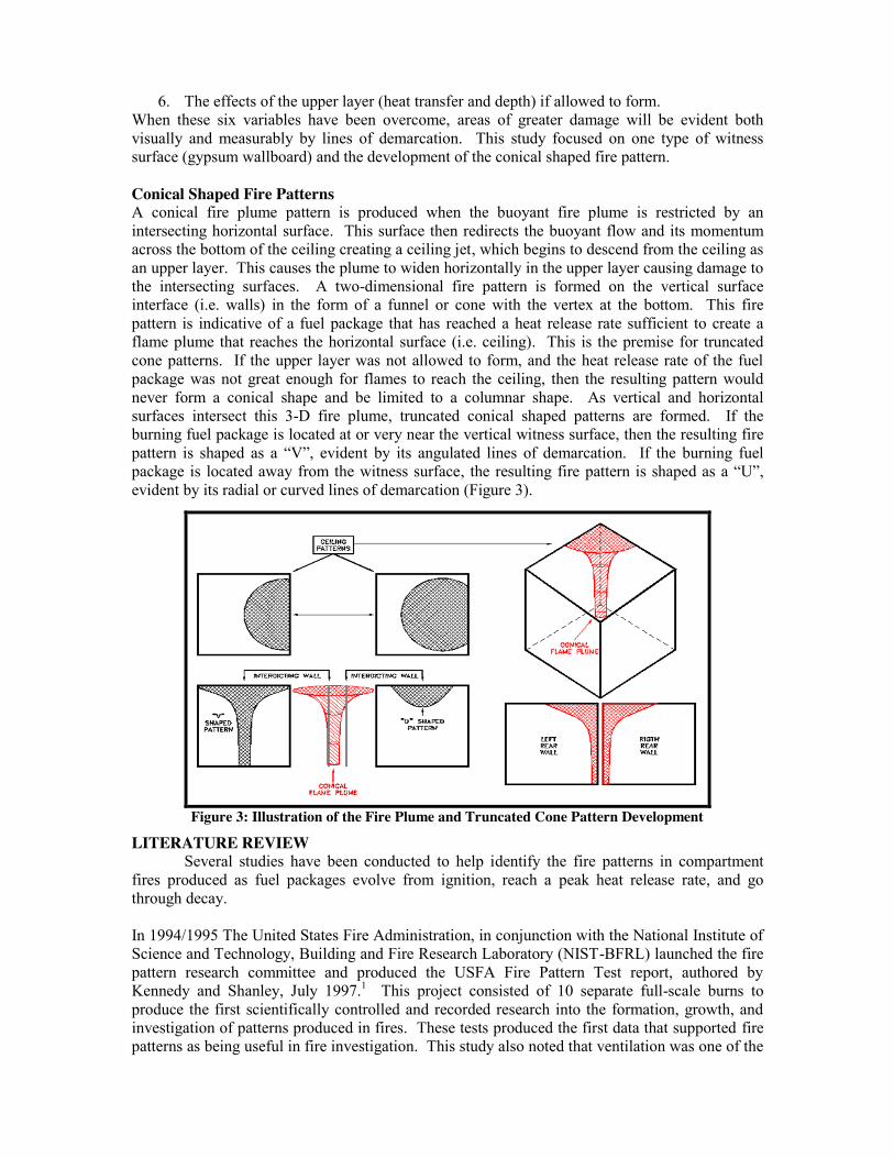
6. The effects of the upper layer (heat transfer and depth) if allowed to form. When these six variables have been overcome, areas of greater damage will be evident both visually and measurably by lines of demarcation. This study focused on one type of witness surface (gypsum wallboard) and the development of the conical shaped fire pattern. Conical Shaped Fire Patterns A conical fire plume pattern is produced when the buoyant fire plume is restricted by an intersecting horizontal surface. This surface then redirects the buoyant flow and its momentum across the bottom of the ceiling creating a ceiling jet, which begins to descend from the ceiling as an upper layer. This causes the plume to widen horizontally in the upper layer causing damage to the intersecting surfaces. A two-dimensional fire pattern is formed on the vertical surface interface (i.e. walls) in the form of a funnel or cone with the vertex at the bottom. This fire pattern is indicative of a fuel package that has reached a heat release rate sufficient to create a flame plume that reaches the horizontal surface (i.e. ceiling). This is the premise for truncated cone patterns. If the upper layer was not allowed to form, and the heat release rate of the fuel package was not great enough for flames to reach the ceiling, then the resulting pattern would never form a conical shape and be limited to a columnar shape. As vertical and horizontal surfaces intersect this 3-D fire plume, truncated conical shaped patterns are formed. If the burning fuel package is located at or very near the vertical witness surface, then the resulting fire pattern is shaped as a “V”, evident by its angulated lines of demarcation. If the burning fuel package is located away from the witness surface, the resulting fire pattern is shaped as a “U”, evident by its radial or curved lines of demarcation (Figure 3).
Figure 3: Illustration of the Fire Plume and Truncated Cone Pattern Development
LITERATURE REVIEW Several studies have been conducted to help identify the fire patterns in compartment fires produced as fuel packages evolve from ignition, reach a peak heat release rate, and go through decay. In 1994/1995 The United States Fire Administration, in conjunction with the National Institute of Science and Technology, Building and Fire Research Laboratory (NIST-BFRL) launched the fire pattern research committee and produced the USFA Fire Pattern Test report, authored by Kennedy and Shanley, July 1997.1 This project consisted of 10 separate full-scale burns to produce the first scientifically controlled and recorded research into the formation, growth, and investigation of patterns produced in fires. These tests produced the first data that supported fire patterns as being useful in fire investigation. This study also noted that ventilation was one of the
most prevalent variables, having the influence to alter or hinder normal fire pattern production. This set the stage for a series of tests in the documentation of the patterns produced in a fire. In June of 1996, two full-scale room fire experiments were performed by Milke & Hill at the University of Maryland.2 The purpose of these tests was to see if duplicate fire pattern formations would evolve from duplicate fuel packages, with a similar ignition point. This resulted in unspecified differences that were attributed to ventilation. In March of 1997, McGarry & Hill, in conjunction with the University of Maryland, continued the full-scale room experiments.3 Two full-size furnished bedrooms were burned at the University of Maryland Fire Rescue Institute Facilities. It was intended that these two burns be identical, to determine if close analysis of the results would discover differences. In both cases, ignition of a gasoline spill next to an upholstered chair was used to initiate the fire. The researchers noted differences, and again attributed these to small variations in the inflow of ventilation air. In December 1997, a full scale room burn fire pattern study was conducted by Putorti at the University of Maryland Fire Rescue Institute.4 This study consisted of four full-scale compartments with similar furniture and flooring, but with two different ignition scenarios (accelerated and non-accelerated). The conclusions of this study were that, while many similarities existed, some differences occurred which were the result of variables beyond control, such as ventilation, oxygen content and the number of experiments conducted. The results were considered inconclusive by the author who called for further study. Beginning in March of 2005, a series of ten full-scale fire pattern studies were conducted by Eastern Kentucky University and the National Association of Fire Investigators (Gorbett, et al., 2006; Hopkins, 2007; Hopkins, 2008). These studies have focused on fire patterns reproducibility, patterns persistence through flashover, and the use of fire patterns in origin determination. In 2006 (Hicks, et al., 2006) embarked upon a fire pattern reproduction study using American National Standards Institute/Underwriters Laboratories (ANSI/UL) Wood Crib for testing of 1-A fire extinguisher rating as a base design. It was during this study that the necessity of a header to form an upper layer, and hence a conical fire pattern, was documented. TEST PROCEDURES Location All burns in this study were conducted at Eastern Kentucky University’s Fire and Explosion Building, located in Richmond, KY. This Building contains a configurable floor plan, with a fixed width American Society for Testing and Materials (ASTM) fire test room for such fire experiments. The burn cells discussed later in the procedures were set up inside this room. Ventilation In almost all previous studies, ventilation was mentioned as being a varying factor affecting the production of fire patterns. By building a test cell inside of one of the Burn Building burn rooms, we were able to limit its effects upon the flame movement. This resulted in a test environment that could be reproduced without extravagant measures or large sums of money, yet allowing us to alleviate much of the air movement that would divert the natural convective fire patterns produced by the fuel package itself. Photography & Film Digital photographs were taken of all the activities. Photographs were taken of each burn prior to and immediately after each burn to document the fire pattern created. Each panel of

drywall was subjected to a depth of calcination study. Then each cell was re-photographed. Video was recorded using a Digital Video Camera. This film was transferred over to Digital Video Disk. Video of all test burns was retained. Depth of Calcination Depth of calcination studies of each cell was performed by a depth caliper with a blunt ended probe. All surveys were performed by the same team to ensure comparable results. This information was documented and graphed and transferred to a spreadsheet. Surveys were performed on all walls and the ceiling. Burn Cell The burn cell for the burns was constructed of 2x4 members, configured to be a 8’wide x 8’2” tall x 8’ deep cell, with 1/2 inch thick drywall wall. One side remained open to facilitate observations, and this is the location where the “header” was placed to facilitate upper layer development. All walls were replaced after each burn. Burn Cell Header (Soffit) Header placement or soffit was lowered 2 times. Initially the soffit extended down from the ceiling 18”, then it was lowered to 30” from the ceiling, and finally placed at 42”. Fuel Package Ten duplicate overstuffed polyurethane foam recliners were utilized in this study. Other researchers would be able to reproduce this study by utilizing similar overstuffed polyurethane recliners. Protocol Burns A single Protocol burn was conducted to determine at what point (loss of mass) in each fuel package the desired fire pattern was produced. This fuel package was allowed to burn to the point at which a visible conical shaped fire pattern was produced. During this test burn, a definable conical fire pattern was achieved and the mass consumption relative to the point of pattern production was noted. Surface Materials Standard grade, 1/2 inch drywall was used for these test cells. This surface material was chosen because it is the most commonly used interior finish for all types of structures. This drywall was purchased and allowed to season to ensure each piece held similar moisture content. It was secured to the test cells by ¼ inch course drywall screws. Weight Measurement Weight measurements were obtained by a commercially available load cell. This load cell was protected by insulation and drywall pieces cut to fit the top of the scale. These weights were tarred (set to zero) each time a new test was performed. The measurements were obtained in ounces, as this was the smallest measurement scale available. Ignition Ignition was provided by the application of a handheld torch until established flame was visible. Each ignition, the source was aimed in a central location of the fuel package, at the middle where the back rest and the seat cushion meet. Temperature Measurement All test burns were monitored with thermocouples, set to log temperature measurement units in Fahrenheit. The rear walls of the cell were prepared with twelve holes drilled for thermocouples. Starting six inches from the top, a whole was drilled. Another was placed 2’ between the second and third, and then 1’on the bottom, 2’ evenly spaced horizontal (fig. 4).

These were centered in the 4’x8’ sheet and off set as mentioned above to facilitate entry of thermocouple probes. This sheet was documented after every burn. This data was collected in Excel spreadsheets and later converted into a line graph form. During each burn, twelve thermocouples were used, with a spacing of three rows of four were used, The rear wall of the cell were prepared with twelve holes drilled for thermocouples (starting six inches from the top, then 2’ between the second and third, and then 1’on the bottom, vertically, with probes spaced 2’ evenly spaced horizontal, see fig. 4). Thermocouple probes were changed out after each test to ensure proper function.
Figure 4: Conical Test - Thermocouple Arrangement
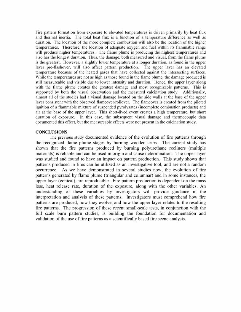
RESULTS This study was able to reproduce similar patterns given duplicate fuel packages (Figures 6-15). The protocol burn was performed to determine a set mass loss associated with producing a conical fire pattern. This allowed researchers to easily reproduce similar patterns based on a set mass loss. Additionally, during the protocol burn a set mass loss of 487 ounces was used for extinguishment. Table 1 lists the starting mass for each chair, the mass loss, and the duration of each test. Another focus of this study was to determine the effects of the upper layer on pattern production. In this study, a varying header height was used to analyze the development of the upper layer and its effects on the resulting pattern. The influence of the upper layer became more pronounced as the header was lowered. An 18” header resulted in a conical pattern with distinct widening in the lines of demarcation at approximately the 4’ level from the ceiling (Figures 5-7). When the header was lowered to 30” from the ceiling, the conical pattern begins to expand at the 4’ 2” mark from the ceiling (Figures 8-10). The next header was lowered to 42” from the ceiling, which resulted in the extension of the conical pattern at the 4’4” mark from the ceiling. This demonstrates that the upper layer development is an important variable in the expansion of the lines of demarcation that are developed.
Figure 5: Pattern Formation
Depth of calcination measurements were taken and recorded using a depth gauge on a one foot by one foot grid. These depths of calcination readings have been transferred onto depth of calcination diagrams for additional pattern comparison (Figures 6-15). Figures 6-15 are
Flame Plume
Eddies Upper Layer
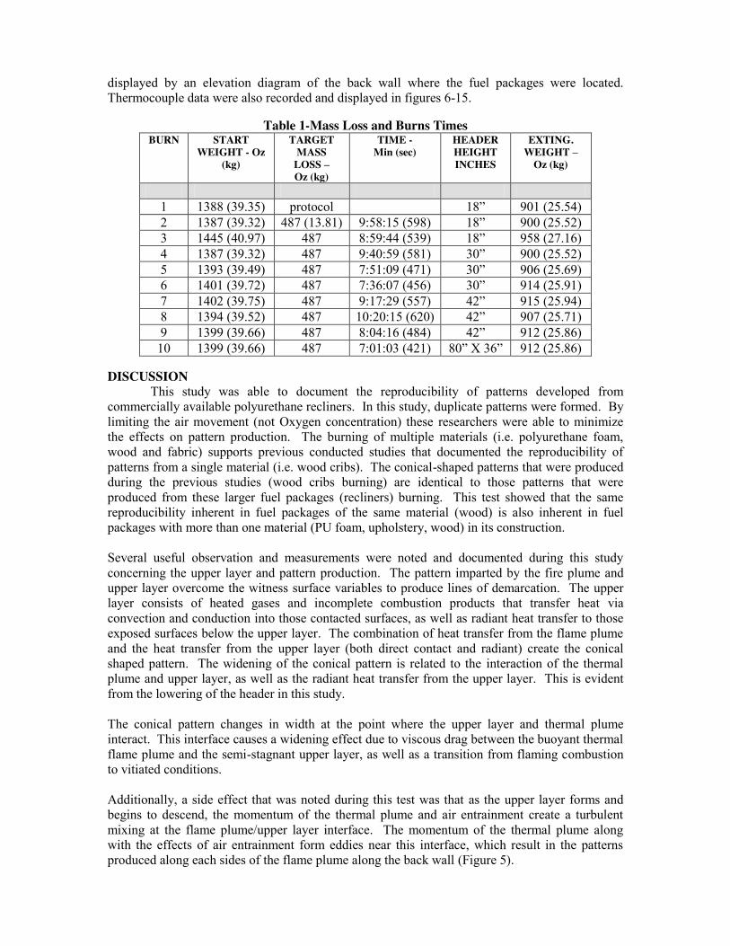
displayed by an elevation diagram of the back wall where the fuel packages were located. Thermocouple data were also recorded and displayed in figures 6-15.
Table 1-Mass Loss and Burns Times BURN
START WEIGHT - Oz
(kg)
TARGET MASS
LOSS – Oz (kg)
TIME - Min (sec)
HEADER HEIGHT INCHES
EXTING. WEIGHT –
Oz (kg)
1 1388 (39.35) protocol 18” 901 (25.54) 2 1387 (39.32) 487 (13.81) 9:58:15 (598) 18” 900 (25.52) 3 1445 (40.97) 487 8:59:44 (539) 18” 958 (27.16) 4 1387 (39.32) 487 9:40:59 (581) 30” 900 (25.52) 5 1393 (39.49) 487 7:51:09 (471) 30” 906 (25.69) 6 1401 (39.72) 487 7:36:07 (456) 30” 914 (25.91) 7 1402 (39.75) 487 9:17:29 (557) 42” 915 (25.94) 8 1394 (39.52) 487 10:20:15 (620) 42” 907 (25.71) 9 1399 (39.66) 487 8:04:16 (484) 42” 912 (25.86) 10 1399 (39.66) 487 7:01:03 (421) 80” X 36” 912 (25.86)
DISCUSSION
This study was able to document the reproducibility of patterns developed from commercially available polyurethane recliners. In this study, duplicate patterns were formed. By limiting the air movement (not Oxygen concentration) these researchers were able to minimize the effects on pattern production. The burning of multiple materials (i.e. polyurethane foam, wood and fabric) supports previous conducted studies that documented the reproducibility of patterns from a single material (i.e. wood cribs). The conical-shaped patterns that were produced during the previous studies (wood cribs burning) are identical to those patterns that were produced from these larger fuel packages (recliners) burning. This test showed that the same reproducibility inherent in fuel packages of the same material (wood) is also inherent in fuel packages with more than one material (PU foam, upholstery, wood) in its construction. Several useful observation and measurements were noted and documented during this study concerning the upper layer and pattern production. The pattern imparted by the fire plume and upper layer overcome the witness surface variables to produce lines of demarcation. The upper layer consists of heated gases and incomplete combustion products that transfer heat via convection and conduction into those contacted surfaces, as well as radiant heat transfer to those exposed surfaces below the upper layer. The combination of heat transfer from the flame plume and the heat transfer from the upper layer (both direct contact and radiant) create the conical shaped pattern. The widening of the conical pattern is related to the interaction of the thermal plume and upper layer, as well as the radiant heat transfer from the upper layer. This is evident from the lowering of the header in this study. The conical pattern changes in width at the point where the upper layer and thermal plume interact. This interface causes a widening effect due to viscous drag between the buoyant thermal flame plume and the semi-stagnant upper layer, as well as a transition from flaming combustion to vitiated conditions. Additionally, a side effect that was noted during this test was that as the upper layer forms and begins to descend, the momentum of the thermal plume and air entrainment create a turbulent mixing at the flame plume/upper layer interface. The momentum of the thermal plume along with the effects of air entrainment form eddies near this interface, which result in the patterns produced along each sides of the flame plume along the back wall (Figure 5).
Fire pattern formation from exposure to elevated temperatures is driven primarily by heat flux and thermal inertia. The total heat flux is a function of a temperature difference as well as duration. The location of the more complete combustion will also be the location of the higher temperatures. Therefore, the location of adequate oxygen and fuel within its flammable range will produce higher temperatures. The flame plume is producing the highest temperatures and also has the longest duration. Thus, the damage, both measured and visual, from the flame plume is the greatest. However, a slightly lower temperature at a longer duration, as found in the upper layer pre-flashover, will also affect pattern production. The upper layer has an elevated temperature because of the heated gases that have collected against the intersecting surfaces. While the temperatures are not as high as those found in the flame plume, the damage produced is still measureable and visible due to lower intensity and duration. Hence, the upper layer along with the flame plume creates the greatest damage and most recognizable patterns. This is supported by both the visual observation and the measured calcination study. Additionally, almost all of the studies had a visual damage located on the side walls at the base of the upper layer consistent with the observed flameover/rollover. The flameover is created from the piloted ignition of a flammable mixture of suspended pyrolyzates (incomplete combustion products) and air at the base of the upper layer. This short-lived event creates a high temperature, but short duration of exposure. In this case, the subsequent visual damage and thermocouple data documented this effect, but the measureable effects were not present in the calcination study. CONCLUSIONS
The previous study documented evidence of the evolution of fire patterns through the recognized flame plume stages by burning wooden cribs. The current study has shown that the fire patterns produced by burning polyurethane recliners (multiple materials) is reliable and can be used in origin and cause determination. The upper layer was studied and found to have an impact on pattern production. This study shows that patterns produced in fires can be utilized as an investigative tool, and are not a random occurrence. As we have demonstrated in several studies now, the evolution of fire patterns generated by flame plume (triangular and columnar) and in some instances, the upper layer (conical), are reproducible. Fire pattern production is dependent on the mass loss, heat release rate, duration of the exposure, along with the other variables. An understanding of these variables by investigators will provide guidance in the interpretation and analysis of these patterns. Investigators must comprehend how fire patterns are produced, how they evolve, and how the upper layer relates to the resulting fire patterns. The progression of these recent small-scale tests, in conjunction with the full scale burn pattern studies, is building the foundation for documentation and validation of the use of fire patterns as a scientifically based fire scene analysis.
Figure 6: Chair 1 18" Header - Actual Damage (left); Calcination Measurements (center); Thermocouple Data (right)
Figure 7: Chair 2 18" Header - Actual Damage (left); Calcination Measurements (center); Thermocouple Data (right)
Figure 8: Chair 3 18" - Actual Damage (left); Calcination Measurements (center); Thermocouple Data (right)
Figure 9: Chair 4 30" Header - Actual Damage (left); Calcination Measurements (center); Thermocouple Data (right)
8' 7' 6' 5' 4' 3' 2' 1' 7' .01 .02 .02 .02 .03 .06 .04 6' 0 .04 .03 .05 .05 .04 .03 5' 0 .01 .02 .04 .05 0 0 4' 0 0 .05 .08 .06 0 0 3' 0 0 .04 .08 .05 0 0 2' 0 0 .08 .07 0 0 0 1' 0 0 .09 1.1 0 0 0
8' 7' 6' 5' 4' 3' 2' 1' 7' .01 .09 .05 .08 .04 .06 .03 6' .01 .05 .06 .05 .04 .05 .03 5' .01 .01 .05 .05 .04 .01 0 4' 0 0 .06 .11 .03 0 0 3' 0 0 .03 .09 .05 0 0 2' 0 0 .09 .15 .10 0 0 1' 0 0 .02 .12 0 0 0
8' 7' 6' 5' 4' 3' 2' 1' 7' .04 .08 .07 .11 .06 .07 .06 6' .03 .08 .06 .12 .06 .09 .03 5' .01 .05 .05 .13 .05 .08 .01 4' 0 0 .05 .08 .06 .01 0 3' 0 0 .04 .10 .18 0 0 2' 0 0 .13 .20 .14 0 0 1' 0 0 0 .12 .08 0 0
8' 7' 6' 5' 4' 3' 2' 1' 7' .10 .09 .14 .16 .10 .13 .10 6' .09 .11 .13 .15 .08 .08 .07 5' .02 .10 .13 .12 .08 .07 .01 4' 0 0 .12 .18 .10 0 0 3' 0 0 .14 .18 .11 0 0 2' 0 0 .18 .18 .12 0 0 1' 0 0 .01 .16 .07 0 0
Figure 10: Chair 5 30" Header - Actual Damage (left); Calcination Measurements (center); Thermocouple Data (right)
Figure 11: Chair 6 30" Header - Actual Damage (left); Calcination Measurements (center); Thermocouple Data (right)
Figure 12: Chair 7 42" Header - Actual Damage (left); Calcination Measurements (center); Thermocouple Data (right)
Figure 13: Chair 8 42" Header - Actual Damage (left); Calcination Measurements (center); Thermocouple Data (right)
8' 7' 6' 5' 4' 3' 2' 1' 7' .13 .15 .14 .17 .09 .14 .13 6' .11 .12 .09 .17 .11 .12 .10 5' .07 .10 .08 .16 .13 .10 .08 4' 0 .07 .13 .13 .11 .08 0 3' 0 0 .08 .18 .13 0 0 2' 0 0 .12 .18 .13 0 0 1' 0 0 .02 .17 .12 0 0
8' 7' 6' 5' 4' 3' 2' 1' 7' .13 .13 .16 .18 .18 1.5 1.3 6' .11 .11 .15 .18 .18 1.4 1.2
5' .09 .09 .13 .19 2.1 .14 1.2 4' .01 .05 .14 .23 2.2 .11 .01 3' 0 0 .14 .20 1.8 .1 0
2' 0 0 .15 2.0 1.7 .08 0 1' 0 0 .12 1.6 1.6 .06 0
8' 7' 6' 5' 4' 3' 2' 1' 7' .15 .18 .19 .21 .20 .15 .15 6' .13 .14 .12 .20 .19 .15 .14 5' .10 .14 .08 .20 .18 .15 .10 4' .08 .08 .15 .20 .15 .09 .08 3' 0 .01 .12 .19 .15 0 0 2' 0 0 .12 .19 .15 0 0 1' 0 0 .02 .15 .10 0 0
8' 7' 6' 5' 4' 3' 2' 1' 7' .12 .10 .17 .16 .14 .12 .1 6' .10 .10 .14 .14 .14 .09 .1 5' .06 .08 .12 .15 .13 .08 .06 4' .05 .05 .11 .15 .12 .06 0 3' 0 0 .19 .15 .12 0 0 2' 0 0 0 .10 .10 0 0 1' 0 0 0 .11 .05 0 0
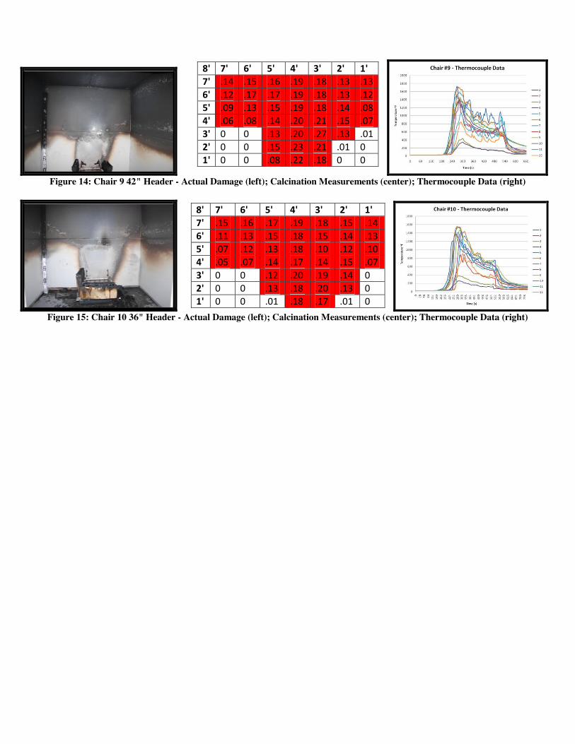
Figure 14: Chair 9 42" Header - Actual Damage (left); Calcination Measurements (center); Thermocouple Data (right)
Figure 15: Chair 10 36" Header - Actual Damage (left); Calcination Measurements (center); Thermocouple Data (right)
8' 7' 6' 5' 4' 3' 2' 1' 7' .14 .15 .16 .19 .18 .13 .13 6' .12 .17 .17 .19 .18 .13 .12 5' .09 .13 .15 .19 .18 .14 .08 4' .06 .08 .14 .20 .21 .15 .07 3' 0 0 .13 .20 .27 .13 .01 2' 0 0 .15 .23 .21 .01 0 1' 0 0 .08 .22 .18 0 0
8' 7' 6' 5' 4' 3' 2' 1' 7' .15 .16 .17 .19 .18 .15 .14 6' .11 .13 .15 .18 .15 .14 .13 5' .07 .12 .13 .18 .10 .12 .10 4' .05 .07 .14 .17 .14 .15 .07 3' 0 0 .12 .20 .19 .14 0 2' 0 0 .13 .18 .20 .13 0 1' 0 0 .01 .18 .17 .01 0

ABOUT THE AUTHORS William D. Hicks, MS, CFEI, CFPS, IAAI-CFI, CFO, MIFireE, Eastern Kentucky University (EKU). Mr. Hicks is employed as Visiting Assistant Professor for the Fire and Safety Engineering Technology Program at EKU. He also serves as the Assistant Chief of the White Hall Fire Department in Madison County, KY. He has completed a Bachelor of Science Degree in Fire & Safety Engineering Technology, with an option in Fire, Arson & Explosion Investigation, and a Master’s of Science Degree in Loss Prevention & Safety, and is in his final year attending the National Fire Academy’s Executive Fire Officer Program. Gregory E. Gorbett, MS, CFEI, CFPS, IAAI-CFI, MIFireE, Eastern Kentucky University (EKU). Mr. Gorbett is employed as an Assistant Professor for the Fire and Safety Engineering Technology Program at EKU. Mr. Gorbett holds two Bachelor of Science degrees, one in Fire Science, and the other in Forensic Science. He holds a MS degree in Executive Fire Service Leadership and is currently pursuing a MS degree in Fire Protection Engineering from WPI. He is also an associate expert with John A. Kennedy & Associates. Michael C. Hopkins, CFEI, CFII, Sadie Fire and Safety, LLC. Mr. Hopkins is Senior Partner with Sadie Fire and Safety Consultants, LLC, and currently serves as a Director of the National Association of Fire Investigators. He has ten years of service with the City of Virginia Beach, with two years as a professional fire investigator. Mr. Hopkins is also a member of the research committee for the Full-Scale Room Burn Pattern Study and is currently pursuing a BS degree in Fire and Safety Engineering Technology. Patrick M. Kennedy, CFEI, CFPS, MIFireE, John A. Kennedy & Associates, USA. Mr. Kennedy is the principle expert for John A. Kennedy & Associates. He holds three Bachelor of Science degrees, including a summa cum laude degree in Fire and Safety Engineering Technology from the University of Cincinnati. He serves as the Chairman of the Board of NAFI, is a member of the NFPA Technical Committee on Fire Investigations, and is Chairman of the NFPA’s Fire Science & Technology Educators Section. Ronald L. Hopkins, MS, CFEI, CFPS, Trace Fire Protection and Safety Consultants, Ltd, USA. Mr. Hopkins is a principle in TRACE Fire Protection and Safety Consultants, Ltd. and retired Associate Professor of the Fire & Safety Engineering Technology program at EKU. He is a member of the NFPA Technical Committee on Fire Investigations and the Technical Committee on Fire Service Professional Qualifications. Mr. Hopkins is Chair of the NAFI National Certification Board, past Chairman of the NFPA’s Fire Science & Technology Educators Section and the ISFSI. James T. Thurman, MS, CFEI, CVFI, Eastern Kentucky University, USA. Mr. Thurman is an Associate Professor in the Fire & Safety Engineering Technology Program at EKU. He is also retired from the Federal Bureau of Investigations, where he served as the Chief of the Bomb Data Center. END NOTES 1 Kennedy, P., and J. Shanley. “USFA Fire Burn Pattern Tests — Program for the Study of Fire Patterns.” FA 178, 7/97 (Federal Emergency Management Agency, United States Fire Administration, Emmitsburg, MD, 1997). 2 Milke, J.A., and Hill, S.M. “Full-Scale Room Fire Experiments Conducted at the University of
Maryland.”, NIST GCR-96-703, National Institute of Standards and Technology, October 1996. 3 McGarry, A.J., and Milke, J.A. “Full-Scale Room Fire Experiments Conducted at the University
of Maryland.”, NIST GCR-97-716, National Institue of Standards and Technology, March 1997 4 Putorti, A.D. “Full-Scale Room Burn Patern Study.”, NIJ Report 601-97, National Institute of
Justice, December 1997. 6 Babrauskas, V., Grayson, S.J. “Heat Release Rates”, Elsevier Applied Science, 1992. p. 370. 7 Hicks, W. Gorbett, G., Hopkins, R., Kennedy, P., and Abney, W., “Advanced Fire Pattern Research Project: Single Fuel Package Fire Pattern Study, ISFSI 2005 Proceedings, 8 Gorbett, G., Hicks, W., Hopkins, R., Kennedy, P., (2006). Full-Scale Burn Patterns Study. ISFSI:
Cincinnati, OH.