Embed Size (px)
Citation preview

COPYRIGHTFujitsu PC Corporation has made every effort to ensure the accuracy and completeness of this document.However, as ongoing development efforts are contin-ually improving the capabilities of our products, we cannot guarantee the accuracy of the contents of thisdocument. We disclaim liability for errors, omissions,or future changes.
Fujitsu and the Fujitsu logo are registered trademarksand LifeBook is a trademark of Fujitsu Limited.
ErgoTrac is a trademark of Fujitsu PC Corporation.
The following are registered trademarks ofIBM Corporation: IBM, IBM PC AT, IBM PS/2.
The following are registered trademarks ofMicrosoft Corporation: MS, MS-DOS, Windows 98.
PCMCIA is a trademark of the Personal ComputerMemory Card International Association.
Phoenix and the Phoenix logo are registered trademarks of Phoenix Technologies, Ltd.
Pentium is a registered trademark and Celeron is a trademark of Intel Corporation.
PC-Doctor is a trademark of Watergate Software, Inc.
LapLink is a registered trademark ofTraveling Software Inc.
All other trademarks mentioned herein are the property of their respective owners.
© Copyright 1999 Fujitsu PC Corporation. All rightsreserved. No part of this publication may be copied,reproduced, or translated, without prior written consent of Fujitsu PC Corporation. No part of thispublication may be stored or transmitted in any electronic form without the written consent ofFujitsu PC Corporation.
For general information, please call:1-888-4-ON-THE-GO.
For Technical Support, please call:1-800-8-FUJITSU.
DECLARATION OF CONFORMITYaccording to FCC Part 15
Responsible Party Name: Fujitsu PC Corporation
Address: 598 Gibraltar DriveMilpitas, CA 95035
Telephone: (408) 935-8800
Declares that product: Model: LifeBook C352LifeBook C360.
Complies with Part 15 of the FCC Rules.
This device complies with Part 15 of the FCC rules.Operations is subject to the following two conditions:(1) This device must not be allowed to cause harmfulinterference, (2) This device must accept any interfer-ence received, including interference that may causeundesired operation.
David Woo Fujitsu 4/11/99
C A U T I O N
Changes or modifications not expresslyapproved by Fujitsu PC Corporation could voidthis user’s authority to operate the equipment.
Shielded interconnect cables must be employed withthis equipment to ensure compliance with the perti-nent RF emission limits governing this device.
Notice to Users of the US Telephone NetworkThe LifeBook™ C Series notebook computers aresupplied with an internal modem which complies
with Part 68 of the FCC rules. On this notebook is a label that contains the FCC Registration Numberand the Ringer Equivalence Number (REN) for thisequipment among other information. If requested,the user must provide their telephone company withthe following information:
1. The telephone number to which the notebook is connected.
2. The Ringer Equivalence Number (REN) for this equipment.
3. That the equipment requires a standard modularjack type USOC RJ-11C which is FCC Part 68 compliant.
4. The FCC Registration Number.
This equipment is designed to be connected to the telephone network or premises wiring using a standardmodular jack type USOC RJ-11C which is FCC Part 68compliant and a line cord between the modem and thetelephone network with a minimum of 26AWG.
The REN is used to determine the number of devicesthat you may connect to your telephone line and stillhave all of those devices ring when your number iscalled. Too many devices on one line may result in failure to ring in response to an incoming call. In most, but not all, areas the sum of the RENs of all ofthe devices should not exceed five (5.0). To be certainof the number of devices you may connect to your line, as determined by the RENs, contact your local telephone company.
If this equipment causes harm to the telephone net-work, your telephone company may discontinue yourservice temporarily. If possible, they will notify you in advance. If advance notice is not practical they willnotify you as soon as possible. You will also be advisedof your right to file a complaint with the FCC.
This fax modem also complies with fax brandingrequirements per FCC Part 68.
Your telephone company will probably ask you to dis-connect this equipment from the telephone networkuntil the problem is corrected and you are sure thatthe equipment is not malfunctioning. This equipmentmay not be used on coin service telephones providedby your telephone company. Connection to party linesis subject to state tariffs. Contact your state’s publicutility commission, public service commission orcorporation commission for more information.
FCC NOTICESNotice to Users of Radios and TelevisionThese limits are designed to provide reasonable protec-tion against harmful interference in a residential instal-lation. This equipment generates, uses, and can radiateradio frequency energy and, if not installed and used in accordance with the instructions, may cause harmfulinterference to radio communications. However, thereis no guarantee that interference will not occur in aparticular installation. If this equipment does causeharmful interference to radio or television reception,which can be determined by turning the equipment off and on, the user is encouraged to try to correct theinterference by one or more of the following measures:
■ Reorient or relocate the receiving antenna.
■ Increase the separation between the equipment and receiver.
■ Connect the equipment into an outlet that is on a different circuit than the receiver.
■ Consult the dealer or an experienced radio/TVtechnician for help.

This equipment includes automatic dialing capability.When programming and/or making test calls to emergency numbers:
■ Remain on the line and briefly explain to the dispatcher the reason for the call.
■ Perform such activities in off-peak hours, such as early morning or late evening.
FCC rules prohibit the use of non-hearing aid compatible telephones in the following locations or applications:
■ All public or semipublic coin-operated or creditcard telephones.
■ Elevators, highways, tunnels (automobile, subway,railroad or pedestrian) where a person withimpaired hearing might be isolated in an emergency.
■ Places where telephones are specifically installed to alert emergency authorities such as fire, police or medical assistance personnel.
■ Hospital rooms, residential health care facilities,convalescent homes and prisons.
■ Workstations for the hearing impaired.
■ Hotel, motel or apartment lobbies.
■ Stores where telephones are used by patrons to order merchandise.
■ Public transportation terminals where telephonesare used to call taxis or to reserve lodging or rental cars.
■ In hotel and motel rooms as at least ten percent of the rooms must contain hearing aid compatibletelephones or jacks for plug-in hearing aid compat-ible telephones which will be provided to hearingimpaired customers on request.
DOC (INDUSTRY CANADA) NOTICESNotice to Users of Radios and TelevisionThis Class B digital apparatus meets all requirements of the Canadian Interference-Causing EquipmentRegulations.
CET appareil numérique de la class B respecte toutes les exigence du Réglement sur le matérial brouilleur du Canada.
Notice to Users of the Canadian Telephone Network The Canadian Industry Canada label identifies certi-fied equipment. This certification means that theequipment meets certain telecommunications net-work protective, operational and safety requirements.The Department does not guarantee the equipmentwill operate to the user’s satisfaction.
The LifeBook C Series notebook computers are supplied with an internal modem which complies with the Industry Canada certification standards fortelecommunication network protection and safetyrequirements. Before connecting this equipment to a telephone line the user should ensure that it is per-missible to connect this equipment to the local tele-communication facilities. The user should be awarethat compliance with the certification standards doesnot prevent service degradation in some situations.
Repairs to telecommunication equipment should bemade by a Canadian authorized maintenance facility. Anyrepairs or alterations not expressly approved by Fujitsu™
PC Corporation or any equipment failures may give thetelecommunication company cause to request the user todisconnect the equipment from the telephone line.
The connecting arrangement code for this equipment is CA11A.
The Load Number is 1.3.
The Load Number assigned to each telephone terminaldevice denotes the percentage of the total load to beconnected to a telephone loop or circuit which is usedby the device to prevent overloading. The terminationon a loop may consist of any combination of devicessuch that the total of the load numbers of all devicesdoes not exceed 100.

Avis Aux Utilisateurs Du Réseau Téléphonique CanadienL’étiquette canadienne Industrie Canada identifiel’équipement certifié. Cette certification signifie que l’équipement satisfait certaines normes de protection, d’exploitation et de sécurité des réseaux de télécommunications. Le département ne garantitpas le fonctionnement de l’équipement à la satisfaction de l’utilisateur.
La série LifeBook C possède un modem interne conforme aux normes de certificationd’Industrie Canada pour protéger les réseaux de télécommunications et satisfaire aux normes de sécurité. Avant de connecter cet équipement à uneligne téléphonique, l’utilisateur doit vérifier s’il est permis de connecter cet équipement aux installationsde télécommunications locales. L’utilisateur est avertique même la conformité aux normes de certification ne peut dans certains cas empêcher la dégradation du service.
Les réparations de l’équipement de télécommunicationsdoivent être effectuées par un service de maintenanceagréé au Canada. Toute réparation ou modification, quin’est pas expressément approuvée par Fujitsu PC Corp.,
C A U T I O N
For safety, users should ensure that theelectrical ground of the power utility, thetelephone lines and the metallic waterpipes are connected together. Usersshould NOT attempt to make suchconnections themselves but shouldcontact the appropriate electric inspectionauthority or electrician. This may beparticularly important in rural areas.
ou toute défaillance de l’équipement peut entraîner la compagnie de télécommunications à exiger que l’utilisateur déconnecte l’équipement de la ligne téléphonique.
Le code d’arrangement de connexion de cetéquipement est CA11A.
Le numéro de charge est 1.3.
Le numéro de charge assigné à chaque terminal téléphonique indique le pourcentage de la charge totale pouvant être connecté à une boucle ou à un circuit téléphonique, utilisé par ce périphérique afin deprévenir toute surcharge. La terminaison d’une bouclepeut être constituée de n’importe quelle combinaisonde périphériques de sorte que le total de numéros decharge de tous les périphériques n’excède pas 100.

UL NOTICE (FOR AUTHORIZED REPAIR TECHNICIANS ONLY)CAUTION: For continued protection against risk of fire, replace only
with the same type and rating fuse.
CAUTION: Danger of explosion if CMOS battery is incorrectly
replaced. Replace only with the same or equivalent type recommended
by the manufacturer. Dispose of used batteries according to the
manufacturer’s instruction.
WARNING: CMOS and NiCAD batteries may explode if mistreated.
Do not recharge, disassemble or dispose of in fire.
A V E R T I S S E M E N T
Pour assurer la sécurité, les utilisateurs doivent vérifier que la prise de terre duservice d’électricité, les lignes télphoniqueset les conduites d’eau métalliques sontconnectées ensemble. Les utilisateurs NEdoivent PAS tenter d’établir ces connexionseux-mêmes, mais doivent contacterles services d’inspection d’installationsélectriques appropriés ou un électricien.Ceci peut être particulièrement importanten régions rurales.

T a b l e o f C o n t e n t s

T a b l e o f C o n t e n t s
ii
PREFACE . . . . . . . . . . . . . . . . . . vi
SECTION ONESETTING UP YOUR LIFEBOOK C SERIES FROM FUJITSU
Unpacking. . . . . . . . . . . . . . . . . . . . 2
Overview of LifeBook C Series Features . . . . 3
Component Identification . . . . . . . . . . . 5
Top and Front Components . . . . . . . . . . 6
Left-side Panel Components . . . . . . . . . . 7
Right-side Panel Components . . . . . . . . . 7
Rear Panel Components . . . . . . . . . . . . 8
Bottom Components . . . . . . . . . . . . . . 9
SECTION TWOSTARTING YOUR LIFEBOOK C SERIESFOR THE FIRST TIME
Power Sources . . . . . . . . . . . . . . . . . 12
Display Panel . . . . . . . . . . . . . . . . . 13
Starting your LifeBook for the First Time . . 13
Registering your LifeBook . . . . . . . . . . 16
Learning About Your Operating System
and Application Software . . . . . . . . . . 17
SECTION THREEUSING YOUR LIFEBOOK C SERIESFROM FUJITSU
Power Button . . . . . . . . . . . . . . . . . 20
Restarting the System . . . . . . . . . . . . . 21
Status Indicator Panel . . . . . . . . . . . . . 22
Batteries . . . . . . . . . . . . . . . . . . . . 26
Integrated ErgoTrac Pointing Device . . . . . 29
Using the Keyboard . . . . . . . . . . . . . . 31
Volume Control . . . . . . . . . . . . . . . . 33
Floppy Disk Drive . . . . . . . . . . . . . . . 33
CD-ROM Drive . . . . . . . . . . . . . . . . 35
Hard Drive . . . . . . . . . . . . . . . . . . . 36
Internal Modem . . . . . . . . . . . . . . . . 37
Power Management . . . . . . . . . . . . . . 38
Data Security . . . . . . . . . . . . . . . . . 43
Pre-installed Software . . . . . . . . . . . . . 44
SECTION FOURCONFIGURING YOUR LIFEBOOK C SERIES FROM FUJITSU
Boot Sequence . . . . . . . . . . . . . . . . . 48
Identifying the Drives . . . . . . . . . . . . . 48
BIOS Setup Utility. . . . . . . . . . . . . . . 49
Navigating Through the Setup Utility . . . . 51
Main Menu – Setting Standard
System Parameters. . . . . . . . . . . . . . 52
Advanced Menu – Setting Device
Feature Controls. . . . . . . . . . . . . . . 62
Security Menu – Setting the
Security Features . . . . . . . . . . . . . . 80
T a b l e o f C o n t e n t sL i f e B o o k C S e r i e s f r o m F u j i t s u
iii
Power Menu – Setting Power
Management Feature Controls . . . . . . . 85
Boot Menu – Selecting the
Operating System Source . . . . . . . . . . 93
Info Menu – Displaying Basic
System Information. . . . . . . . . . . . . 97
Exit Menu – Leaving the Setup Utility . . . . 99
Setting Up Your Save-To-Disk
File Allocation . . . . . . . . . . . . . . . 102
SECTION FIVEUSER INSTALLABLE FEATURES
Lithium ion Battery . . . . . . . . . . . . . 106
PC Cards . . . . . . . . . . . . . . . . . . . 108
Parallel Port Devices . . . . . . . . . . . . . 110
Serial Port Devices . . . . . . . . . . . . . . 110
USB Devices . . . . . . . . . . . . . . . . . 110
Microphone . . . . . . . . . . . . . . . . . 110
Stereo Line In Devices . . . . . . . . . . . . 110
Headphones . . . . . . . . . . . . . . . . . 110
Telephone Lines . . . . . . . . . . . . . . . 111
Mouse, Keyboard, or Keypad . . . . . . . . 111
External Monitor . . . . . . . . . . . . . . . 111
Theft Prevention Lock . . . . . . . . . . . . 112
Memory Upgrade Module . . . . . . . . . . 112
SECTION SIXTROUBLESHOOTING
Identifying the Problem . . . . . . . . . . . 118
Specific Problems . . . . . . . . . . . . . . 119
Power On Self Test Messages . . . . . . . . 138
Emergency CD-ROM
Tray Release . . . . . . . . . . . . . . . . 141
Modem Setup and Commands . . . . . . . 141
Recovery CD-ROM . . . . . . . . . . . . . 142
SECTION SEVENCARE AND MAINTENANCE
Caring for Your Notebook . . . . . . . . . . 146
Increasing Battery Life . . . . . . . . . . . . 147
Caring for Your Batteries . . . . . . . . . . 147
APPENDIX A SPECIFICATIONSWarranty . . . . . . . . . . . . . . . . . . . 150
LifeBook C Series Specifications . . . . . . 150
Approvals . . . . . . . . . . . . . . . . . . . 153
Popular Accessories . . . . . . . . . . . . . 153
APPENDIX B GLOSSARYGlossary. . . . . . . . . . . . . . . . . . . . 154
INDEXIndex . . . . . . . . . . . . . . . . . . . . . 161

L i f e B o o k C S e r i e s f r o m F u j i t s uP r e f a c e

P r e f a c e
vi
PREFACEThe LifeBook C Series from Fujitsu PCCorporation is a powerful notebook computer.It is powered by an Intel Pentium® II or Celeronmicroprocessor, has an XGA or SVGA colorTFT display, a built-in floppy drive, a CD-ROMdrive and an internal 56K modem with v.90support. The LifeBook C Series brings thecomputing power of desktop personal comput-ers (PCs) to a portable environment.
This manual explains how to operate yourLifeBook C Series’ hardware and built-insystem software. The LifeBook C Series iscompatible with the IBM® PC AT. It comeswith Windows 98 pre-installed.
A LifeBook C Series notebook has a powerfulinterface that enables it to support a variety ofoptional features and software. (Figure P-1.)
CONVENTIONS USED IN THE GUIDEScreen examples in this manual are intended asexamples only, and screen and file names maydiffer in actual use.
Messages displayed by the LifeBook C Seriesappear in Courier type.Example: Shutdown the computer?
Keyboard keys are shown in boldface Helvetica type.Example: Fn, F1, Esc, and Ctrl.
Pages with additional information about a spe-cific topic are cross-referenced within the text.Example: (See page xx.)
P O I N T
The point icon highlights informationthat will enhance your understandingof the subject material.
C A U T I O N
The caution icon highlights informationthat is important for your safety, the safe operation of your computer, or theintegrity of your files. Please read all caution information carefully.

L i f e B o o k C S e r i e s f r o m F u j i t s uL i f e B o o k C S e r i e s f r o m F u j i t s u
vii
Figure P-1 LifeBook C Series with Samples of Fujitsu and
Third Party Options and Accessories

Sett ing Up Your L i feBook C Ser iesS e c t i o n O n e
Unpacking . . . . . . . . . . . . . . . . . . . 2
Overview of LifeBook C Series Features . . . . 3
Component Identification . . . . . . . . . . . 5
Top and Front Components . . . . . . . . . . 6
Left-side Panel Components . . . . . . . . . . 7
Right-side Panel Components . . . . . . . . . 7
Rear Panel Components . . . . . . . . . . . . 8
Bottom Components . . . . . . . . . . . . . . 9
S e c t i o n O n e
2
Section OneSETTING UP YOUR LIFEBOOK C SERIES FROM FUJITSUThis section describes how to set up yourLifeBook C Series from Fujitsu. We stronglyrecommend that you read it before using yournotebook – even if you are already familiar withnotebook computers.
UNPACKINGWhen you receive your notebook, unpack itcarefully, and compare the parts you havereceived with the items listed below.
For a standard configuration you should have:
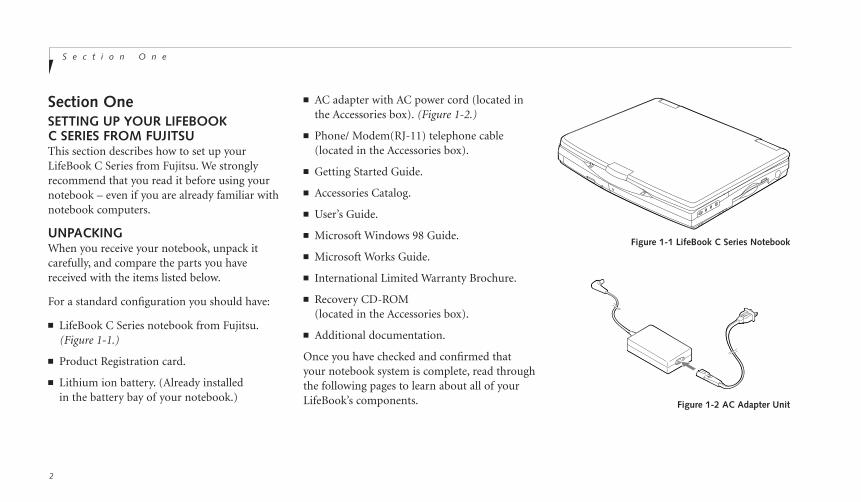
■ LifeBook C Series notebook from Fujitsu.(Figure 1-1.)
■ Product Registration card.
■ Lithium ion battery. (Already installed in the battery bay of your notebook.)
■ AC adapter with AC power cord (located inthe Accessories box). (Figure 1-2.)
■ Phone/ Modem(RJ-11) telephone cable(located in the Accessories box).
■ Getting Started Guide.
■ Accessories Catalog.
■ User’s Guide.
■ Microsoft Windows 98 Guide.
■ Microsoft Works Guide.
■ International Limited Warranty Brochure.
■ Recovery CD-ROM(located in the Accessories box).
■ Additional documentation.
Once you have checked and confirmed thatyour notebook system is complete, read throughthe following pages to learn about all of yourLifeBook’s components.
Figure 1-1 LifeBook C Series Notebook
Figure 1-2 AC Adapter Unit

On
e
S e t t i n g U p Y o u r L i f e B o o k C S e r i e sL i f e B o o k C S e r i e s f r o m F u j i t s u
3
OVERVIEW OF LIFEBOOK C SERIES FEATURESThe LifeBook C Series is a compact, yet powerful notebook computer available withstandard features including: (See Appendix A,pages 150–153, for detailed information on individual models.)
■ 333MHz Intel Pentium II processor (C360)or 333MHz Intel Celeron processor (C352).
■ 64MB SDRAM standard, expandable to128MB(C360) or 32MB SDRAM standard,expandable to 96MB(C352).
■ 13.3" XGA TFT color display(C360), or 12.1" SVGA TFT color display(C352).
■ 2MB video RAM.
■ Built-in 4.3 GB hard drive.
■ Lithium ion battery.
■ Internal 56K fax/data/voice modem with v.90 support.
■ Full audio and video features:
■ 16-bit SoundBlaster Pro-compatible sound chip.
■ Zoomed Video support for full motionvideo acceleration.
■ Built-in stereo speakers.
■ Built-in mono microphone.
■ Stereo line in jack.
■ Stereo headphone jack.
■ Microphone jack.
■ Combination PC card slot accommodates 2 Type II or 1 Type III Cards.
■ Integrated ErgoTrac™ pointing device forsuperb cursor control and comfort.
■ External monitor support with simultaneousdisplay capabilities.
■ Full-size keyboard with three dedicatedWindows keys.
■ Hot swappable PS/2 port forexternal components.
C A U T I O N
The internal modem is designed to theITU-T V.90 standard. Its maximum speedof 53000bps is the highest allowed byFCC, and its actual connection ratedepends on the line conditions. Themaximum speed is 33600bpd at upload.
C A U T I O N
The internal modem is not intended foruse with Digital PBX systems. Do notconnect the internal modem to a digitalPBX as it may cause serious damage tothe internal modem or your entire note-book. Consult your PBX manufacturer’sdocumentation for details. Some hotelshave Digital PBX systems. Be sure to findout BEFORE you connect your modem.
S e c t i o n O n e
4
■ Standard user install software:
■ AOL Free Trial.
■ CompuServe.™
■ AT&T WorldNet.™
■ Prodigy Internet
■ Netscape® Communicator.
■ USB device support.
■ Standard pre-installed software:
■ Microsoft Windows 98 operating system.
■ LapLink for file transfers.(Cable not provided.)
■ Microsoft Works for business applicationsincluding word processing, spreadsheets and databases.
■ Quicken Basic 99 for money management.
■ PC-Doctor for system diagnostics.
■ PMSet 98 for system power management.
■ McAfee VirusScan for virus protection.
■ Adobe Acrobat Reader.
■ ESS AudioRack™ for playback of Audio CDand other Audio Controls.
P O I N T
This unit does not come pre-installedwith the Windows 95 or Windows NToperating systems. Windows 98 is theonly operating system supported onyour notebook.
P O I N T
Windows 98 comes pre-installed withInternet Explorer 4.01.

On
e
S e t t i n g U p Y o u r L i f e B o o k C S e r i e sL i f e B o o k C S e r i e s f r o m F u j i t s u
5
Figure 1-3 LifeBook C352 with Display Open
Display Panel
Status Indicator Panel
Keyboard
ErgoTrac Pointing Device
CD-ROM Drive
Closed Cover Switch
Built-in Microphone
Display Panel Latch
COMPONENT IDENTIFICATIONFor detailed specifications refer to Appendix A on pages 150–153.
Brightness Control
Power and Suspend/Resume Button
Floppy Disk Drive
Left Speaker
Right Speaker
S e c t i o n O n e
6
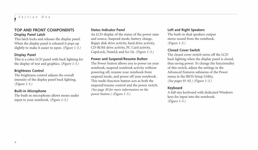
TOP AND FRONT COMPONENTSDisplay Panel LatchThis latch locks and releases the display panel.When the display panel is released it pops upslightly to make it easier to open. (Figure 1-3.)
Display PanelThis is a color LCD panel with back lighting forthe display of text and graphics. (Figure 1-3.)
Brightness ControlThe brightness control adjusts the overallintensity of the display panel back lighting.(Figure 1-3.)
Built-in MicrophoneThe built-in microphone allows mono audioinput to your notebook. (Figure 1-3.)
Status Indicator PanelAn LCD display of the status of the power stateand source, Suspend mode, battery charge,floppy disk drive activity, hard drive activity,CD-ROM drive activity, PC Card activity,CapsLock, NumLk and Scr Lk. (Figure 1-3.)
Power and Suspend/Resume ButtonThe Power button allows you to power on yournotebook, suspend notebook activity withoutpowering off, resume your notebook from suspend mode, and power off your notebook.This multi-function button acts as both thesuspend/resume control and the power switch.(See page 20 for more information on the power button.) (Figure 1-3.)
Left and Right SpeakersThe built-in dual speakers output stereo sound from the notebook.(Figure 1-3.)
Closed Cover SwitchThe closed cover switch turns off the LCD back lighting when the display panel is closed,thus saving power. To change the functionalityof this switch, adjust the settings in theAdvanced Features submenu of the Powermenu in the BIOS Setup Utility.(See pages 91-92.) (Figure 1-3.)
KeyboardA full-size keyboard with dedicated Windowskeys for input into the notebook.(Figure 1-3.)

On
e
S e t t i n g U p Y o u r L i f e B o o k C S e r i e sL i f e B o o k C S e r i e s f r o m F u j i t s u
7
ErgoTrac Pointing DeviceThe integrated ErgoTrac pointing device iscomposed of a short, comfortable, dish-shapedfinger mouse and two buttons. Its button-likeshape is both responsive and comfortable foryour finger when rocked gently. (Figure 1-3.)
CD-ROM driveA 24x maximum CD-ROM drive.(Figure 1-3.)
LEFT-SIDE PANEL COMPONENTS
PC Card SlotsThe PC Card Slots allow you to install two TypeII PC Cards or one Type III PC Card. (See pages108-110 for more information on PC Cards.)The button to the left of the card slots locksthe card(s) in place, and the buttons to the right of the slots eject the card(s) from the slots.(Figure 1-4.)
RIGHT-SIDE PANEL COMPONENTSVolume ControlThe volume control is a knob which providesmanual control of the sound level of all audiooutput from your notebook. (Figure 1-5.)
Headphone JackYou can connect headphones or powered external speakers to the headphone jack.(Figure 1-5.)
Stereo Line In JackThe stereo line in jack allows you to connect anexternal audio source to your notebook, like anaudio cassette player. This jack will not supportan external microphone. (Figure 1-5.)
Figure 1-4 LifeBook C Series Left-side Panel
PC Card Eject Buttons
PC Card SlotsPC Card Lock
Figure 1-5 LifeBook C Series Right-side Panel
Stereo LineIn Jack
MicrophoneJack
PS/2Port
Volume Control
Headphone Jack FloppyDisk Drive

S e c t i o n O n e
8
C A U T I O N
The internal modem is not intended foruse with Digital PBX systems. Do notconnect the internal modem to a digitalPBX as it may cause serious damage tothe internal modem or your entire note-book. Consult your PBX manufacturer’sdocumentation for details. Some hotelshave Digital PBX systems. Be sure to findout BEFORE you connect your modem.
Parallel PortThe parallel port allows you to connectparallel devices, such as a parallel printer toyour notebook. (This is also sometimesreferred to as an LPT port.) (Figure 1-6.)
Microphone JackThe microphone jack allows you to connect anexternal mono microphone. (Figure 1-5.)
Floppy Disk DriveThe floppy disk drive provides removable datastorage. (Figure 1-5.)
PS/2 PortThe port allows you to connect an externalPS/2 keyboard, mouse, or numeric keypad.(Figure 1-5.)
REAR PANEL COMPONENTSReset ButtonThe Reset button is for restarting your note-book in the event that your operating systemhas halted and cannot be restarted by the CTRL+ALT+DEL keys. (Figure 1-6.)
C A U T I O N
There are also software volume controls.The knob setting and the software settingswill interact. Be sure to check both thesoftware volume control and the knob onyour notebook if you are experiencingproblems. (See Volume Control on page33 for more information.)
Figure 1-6 LifeBook C Series Rear Panel
Reset Button
Parallel Port
Serial Port
Cooling Fan
External Monitor Port
Modem(RJ-11) Jack
DC Power Jack
USB Port Anti-theftLock Slot
DC Power JackThe DC power jack allows you to plug in theAC adapter or the optional auto/airline adapterto power the notebook and charge the internalLithium ion Battery. (Figure 1-6.)
On
e
S e t t i n g U p Y o u r L i f e B o o k C S e r i e sL i f e B o o k C S e r i e s f r o m F u j i t s u
9
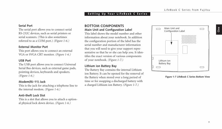
BOTTOM COMPONENTSMain Unit and Configuration LabelThis label shows the model number and otherinformation about your notebook. In additionthe configuration portion of the label has theserial number and manufacturer informationthat you will need to give your support repre-sentative so that he or she can help you. It iden-tifies the exact version of various componentsof your notebook. (Figure 1-7.)
Lithium ion Battery Bay The Battery Bay contains the internal Lithiumion Battery. It can be opened for the removal ofthe Battery when stored over a long period oftime or for swapping a discharged battery witha charged Lithium ion Battery. (Figure 1-7.)
Serial PortThe serial port allows you to connect serial RS-232C devices, such as serial printers or serial scanners. (This is also sometimes referred to as a COM port.) (Figure 1-6.)
External Monitor PortThis port allows you to connect an externalVGA or SVGA CRT monitor. (Figure 1-6.)
USB PortThe USB port allows you to connect UniversalSerial Bus devices, such as external game pads,pointing devices, keyboards and speakers.(Figure 1-6.)
Modem(RJ-11) JackThis is the jack for attaching a telephone line tothe internal modem. (Figure 1-6.)
Anti-theft Lock SlotThis is a slot that allows you to attach a option-al physical lock down device. (Figure 1-6.)
Lithium ionBattery Bay
Main Unit andConfiguration Label
Figure 1-7 LifeBook C Series Bottom View
Starting Your LifeBook C Series from FujitsuS e c t i o n T w o
Power Sources . . . . . . . . . . . . . . . . 12
Display Panel . . . . . . . . . . . . . . . . . 13
Starting your LifeBook for the First Time . . . 13
Registering your LifeBook . . . . . . . . . . 16
Learning About Your Operating Systemand Application Software. . . . . . . . . . 17
S e c t i o n T w o
12
SECTION TWOSTARTING YOUR LIFEBOOK C SERIESFROM FUJITSUThis section describes the initial power on andsetup of your notebook. It provides informa-tion on power sources, powering on, shuttingdown, initial software setup and the registrationof your LifeBook C Series.
POWER SOURCESYour notebook has three possible powersources: the internal Lithium ion battery; theAC adapter; or an optional auto/airline adapter.
Connecting the Power AdaptersThe AC adapter or an optional auto/airlineadapter provides power for operating yournotebook and charging the battery.(Figure 1-2.)
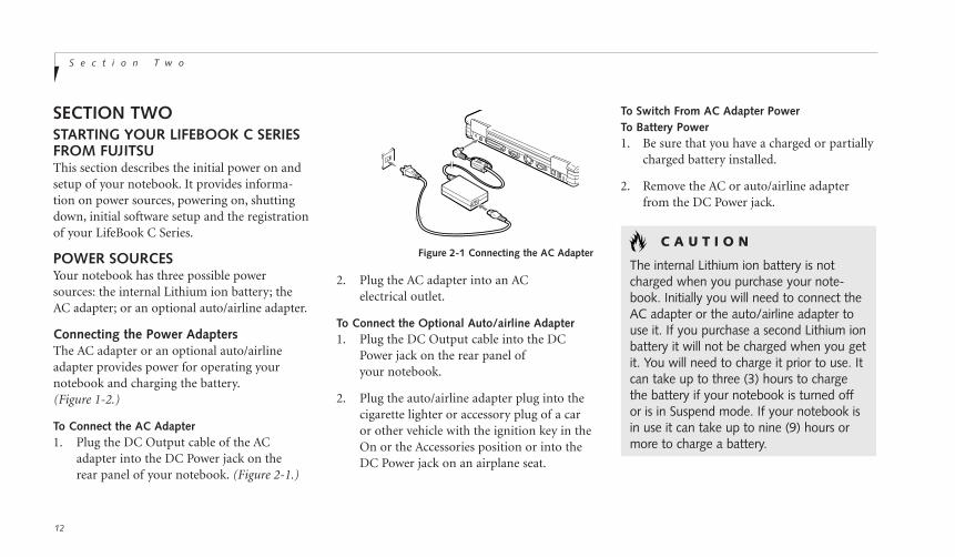
To Connect the AC Adapter1. Plug the DC Output cable of the AC
adapter into the DC Power jack on the rear panel of your notebook. (Figure 2-1.)
Figure 2-1 Connecting the AC Adapter
2. Plug the AC adapter into an ACelectrical outlet.
To Connect the Optional Auto/airline Adapter1. Plug the DC Output cable into the DC
Power jack on the rear panel ofyour notebook.
2. Plug the auto/airline adapter plug into thecigarette lighter or accessory plug of a caror other vehicle with the ignition key in theOn or the Accessories position or into theDC Power jack on an airplane seat.
To Switch From AC Adapter Power To Battery Power1. Be sure that you have a charged or partially
charged battery installed.
2. Remove the AC or auto/airline adapterfrom the DC Power jack.
C A U T I O N
The internal Lithium ion battery is notcharged when you purchase your note-book. Initially you will need to connect theAC adapter or the auto/airline adapter touse it. If you purchase a second Lithium ionbattery it will not be charged when you getit. You will need to charge it prior to use. Itcan take up to three (3) hours to chargethe battery if your notebook is turned offor is in Suspend mode. If your notebook isin use it can take up to nine (9) hours ormore to charge a battery.

Two
S t a r t i n g Y o u r L i f e B o o k C S e r i e sL i f e B o o k C S e r i e s f r o m F u j i t s u
13
DISPLAY PANELOpening the Display PanelLifting the latch releases the top of the displaypanel from the front of the notebook body.When the display panel is released it pops upslightly to make it easier to open. Lift the dis-play panel backward until the screen is at acomfortable viewing angle. (Figure 2-2.)
P O I N T
The higher the brightness level, the morepower the notebook will consume andthe faster your battery will discharge. Formaximum battery life, make sure that thebrightness is set as low as possible.
STARTING YOUR LIFEBOOK FOR THE FIRST TIMEPower OnThe Power Button is located above your key-board to the right of the Status Indicator Panel.This button is always used to Power On yournotebook from its Off state. Once you haveconnected your AC adapter or have chargedyour internal Lithium ion Battery, you can pressthis button to Power On your notebook.
Figure 2-2 Opening the Display Panel
C A U T I O N
When you turn on your notebook besure you have a power source. Thismeans that the internal Lithium ionBattery is installed and charged, or thatthe AC adapter or the auto/airlineadapter is connected and has power.
S e c t i o n T w o
14
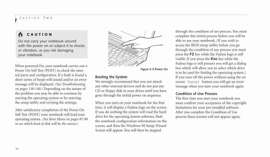
When powered On, your notebook carries out aPower On Self Test (POST) to check the inter-nal parts and configuration. If a fault is found ashort series of beeps will sound and/or an errormessage will be displayed. (See Troubleshootingon pages 138-140.) Depending on the nature ofthe problem you may be able to continue bystarting the operating system or by entering the setup utility and revising the settings.
After satisfactory completion of the Power OnSelf Test (POST) your notebook will load youroperating system. (See Boot Menu on pages 87-90to see which kind of disk will be the source.)
Figure 2-3 Power On
C A U T I O N
Do not carry your notebook around with the power on or subject it to shocksor vibration, as you risk damaging your notebook.
through the condition of use process. You mustcomplete this initial process before you will beable to use your notebook. (If you wish toaccess the BIOS setup utility before you gothrough the condition of use process you mustpress the F2 key while the Fujitsu logo is stillvisible. If you press the Esc key while theFujitsu logo is still present you will get a dialogbox which will allow you to select which driveis to be used for finding the operating system.)If you turn off the power without using the onscreen Cancel button you will get an errormessage when you start your notebook again.
Condition of Use ProcessThe first time you start your notebook youmust confirm your acceptance of the copyrightlimitations for your pre-installed software.After you complete the Condition of Useprocess these screens will not appear again.
Booting the SystemWe strongly recommend that you not attachany other external devices and do not put anyCD or floppy disk in your drives until you havegone through the initial power on sequence.
When you turn on your notebook for the firsttime, it will display a Fujitsu logo on the screen.If you do nothing the system will read the harddrive for the operating system software, flashthe notebook configuration information on thescreen, and then the Windows 98 Setup WizardScreen will appear. You will then be stepped

Two
S t a r t i n g Y o u r L i f e B o o k C S e r i e sL i f e B o o k C S e r i e s f r o m F u j i t s u
15
You cannot use your notebook until thisCondition of Use process is completed. Thebottom of each screen has a <Back button, aNext> Button and a Cancel button whichare activated by the integrated ErgoTrac cursorcontrol and button click. The <Back buttonwill return you to the previous screen. TheNext> button activates any choices or information you have entered and takes you onto the next screen. The Cancel button allowsyou to stop the setup process.
If you stop the process your notebook will start up at the beginning of the Windows 98Setup Wizard.
The screens you will be required to respond toare described with the required action.
User InformationFill in your name and your company name asyou want the software licensed. To step from thename field to the company field press the Tabkey. When the information has been entered clickon the Next> button. You will not be allowedto continue until you make an entry.
License AgreementRead the license agreement carefully. You canscroll through the text using the integratedErgoTrac or TouchPad pointing device to acti-vate the scroll bar or use the up arrow Õ anddown arrow Ô keys to move up and down thetext one line at a time, or use the Page Up andPage Down keys to move the text one screen ata time. When you finish reading you mustaccept or reject the terms of the agreement and then click on the Next> button.
Product KeyLook in the box that your notebook came inand you will find a Windows 98 Certificate ofAuthenticity shrink wrapped with the Windows98 Users manual. On the certificate you willfind a bar-code with a number above it. This isyour product key and the number you shouldenter on the Product Key screen. When youhave entered the number exactly as shown thenclick on the Next> button.
Start WizardThe Start Wizard screen will appear when youhave entered a valid product key. When youclick on the Finish button the display will flashvarious screens as the system identifies whathardware is installed.
Time ZoneWhen your notebook has completely identifiedall of the installed hardware, it will display adialog box for entering which time zone youwish to set the clock to.
P O I N T
If you reject the terms of the licenseagreement you will be asked to reviewthe license agreement for information onreturning Windows 98 or to shut downyour notebook.

How do I register?By modem, fax, mail, telephone, or on the web.With Windows 98, you can access the Softbank E-Registration program by selecting theRegister Now option in the Welcome toWindows 98 wizard menu. This menu appearsthe first time you start Windows 98 after com-pleting the Condition of Use process. To accessthe Welcome to Windows 98 wizard anytime,double-click on the Welcome to Windows 98icon on your desktop.
You may also complete the pre-printedregistration form and either:
fax it to 1-949-450-9140
or mail it to:Fujitsu PC Corporation 15355 Barranca PkwyIrvine, CA 92618-9520
or call: 1-800-8fujitsu (1-800-838-5487)
You may also register on our website:www.8fujitsu.com. You will need to be set up with an Internet Service Provider(ISP) to usethis option.
S e c t i o n T w o
16
Printer SetupWhen the time zone setup is complete, a dialogbox will appear for selecting which printer is tobe attached to your notebook. You do not haveto select a printer at this time. If you do notwish to select a printer, click on the Cancelbutton. If you do wish to select a printerclick on the Next button and answerthe questions.
Welcome to Windows 98When you boot into Windows 98 for the firsttime, you will see a Welcome to Windows 98dialog box with several options. Select the firstoption, Register Now, to register yourLifeBook C Series notebook.
P O I N T
You will find a Emergency Recovery CD-ROM packet in your accessoriesbox. Please store the packet in a safeplace in case there is a loss of dataand it becomes necessary to re-installyour operating system and/or applicationprograms. (See Restoring Your Pre-installed Software from the RecoveryCD-ROM on page 142.)
REGISTERING YOUR LIFEBOOKWhat are the benefits of registering?You will receive an identification label for yourLifeBook, which, if your LifeBook is ever lost,may help in getting it returned to you. You alsoreceive priority Personal Identification Number(PIN), technical support access and usefulproduct mailings. Proof of purchase is notrequired if you register within 30 days ofyour purchase.
P O I N T
Windows 98 will briefly initialize a systemdevice before displaying the Windowsdesktop for the first time.
Two
S t a r t i n g Y o u r L i f e B o o k C S e r i e sL i f e B o o k C S e r i e s f r o m F u j i t s u
17
LEARNING ABOUT YOUR OPERATINGSYSTEM AND APPLICATION SOFTWARE
TutorialsAll operating systems and most software appli-cations have tutorials built-in. We highly rec-ommend that you step through the tutorialbefore you use an application even if youare familiar with the same application ona different machine, an earlier version ofthe application, or a similar product.
ManualsIn the accessories box you will find manualsfor Windows 98.
Software manuals of pre-installed softwareare available online. See the help screens of yourpre-installed software. We recommend that youreview the on-line documentation for generalinformation on the use of these applicationsand to get a basic understanding of what is covered and how it is organized, should questions arise as you use the applications.
Links to Fujitsu On-lineYou can go directly to the Fujitsu Accessoriescatalog for your notebook by clicking on theLifeBook Accessories Website option from theWindows Start menu. This will take you to theWeb site for Fujitsu Lifebook accessories.
You can also reach the Fujitsu Service andSupport Web site on-line by choosing theService & Support option in the Service andSupport folder in the Windows Start menu.Alternately, you may call: 1-800-8fujitsu(1-800-838-5487)
Using Your LifeBook C Series from FujitsuS e c t i o n T h r e e
Power Button . . . . . . . . . . . . . . . . . 20
Restarting the System . . . . . . . . . . . . 21
Status Indicator Panel. . . . . . . . . . . . . 22
Batteries . . . . . . . . . . . . . . . . . . . 26
Integrated ErgoTrac Pointing Device . . . . . 29
Using the Keyboard. . . . . . . . . . . . . . 31
Volume Control . . . . . . . . . . . . . . . . 33
Floppy Disk Drive. . . . . . . . . . . . . . . 33
CD-ROM Drive . . . . . . . . . . . . . . . . 35
Hard Drive . . . . . . . . . . . . . . . . . . 36
Internal Modem . . . . . . . . . . . . . . . 37
Power Management . . . . . . . . . . . . . 38
Data Security . . . . . . . . . . . . . . . . . 43
Pre-installed Software . . . . . . . . . . . . 44
SECTION THREEUSING YOUR LIFEBOOK C SERIESFROM FUJITSUThis section describes the indicators, buttons,connections, operating modes, and software ofyour LifeBook C Series and their uses.
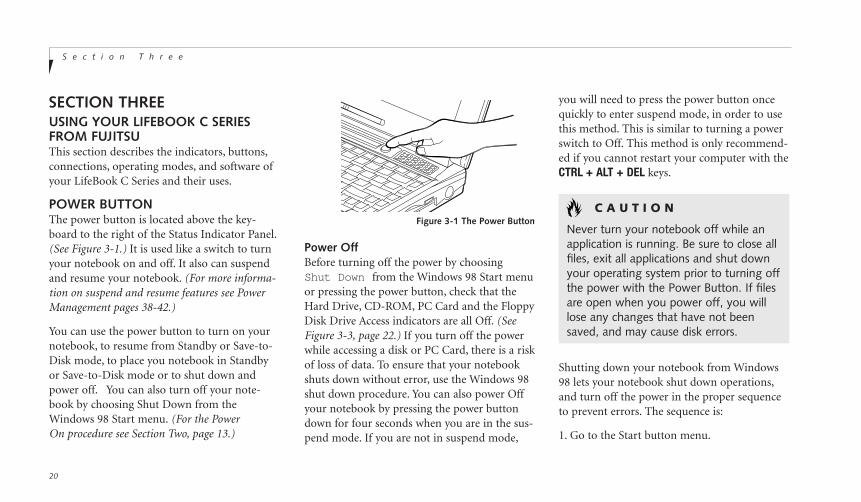
POWER BUTTONThe power button is located above the key-board to the right of the Status Indicator Panel.(See Figure 3-1.) It is used like a switch to turnyour notebook on and off. It also can suspendand resume your notebook. (For more informa-tion on suspend and resume features see PowerManagement pages 38-42.)
You can use the power button to turn on yournotebook, to resume from Standby or Save-to-Disk mode, to place you notebook in Standbyor Save-to-Disk mode or to shut down andpower off. You can also turn off your note-book by choosing Shut Down from theWindows 98 Start menu. (For the PowerOn procedure see Section Two, page 13.)
S e c t i o n T h r e e
20
Shutting down your notebook from Windows98 lets your notebook shut down operations,and turn off the power in the proper sequenceto prevent errors. The sequence is:
1. Go to the Start button menu.
Power OffBefore turning off the power by choosingShut Down from the Windows 98 Start menuor pressing the power button, check that theHard Drive, CD-ROM, PC Card and the FloppyDisk Drive Access indicators are all Off. (SeeFigure 3-3, page 22.) If you turn off the powerwhile accessing a disk or PC Card, there is a riskof loss of data. To ensure that your notebookshuts down without error, use the Windows 98shut down procedure. You can also power Offyour notebook by pressing the power buttondown for four seconds when you are in the sus-pend mode. If you are not in suspend mode,
you will need to press the power button oncequickly to enter suspend mode, in order to usethis method. This is similar to turning a powerswitch to Off. This method is only recommend-ed if you cannot restart your computer with theCTRL + ALT + DEL keys.
C A U T I O N
Never turn your notebook off while anapplication is running. Be sure to close allfiles, exit all applications and shut downyour operating system prior to turning offthe power with the Power Button. If filesare open when you power off, you willlose any changes that have not beensaved, and may cause disk errors.
Figure 3-1 The Power Button
Th
ree
U s i n g Y o u r L i f e B o o k C S e r i e sL i f e B o o k C S e r i e s f r o m F u j i t s u
21
P O I N T
If you are going to store your notebookfor an extended period of time, take thefollowing precautions:1. Remove any CD and/or floppy disk.2. Shut down with Windows 98 to
power Off your notebook.3. Close your notebook display panel.4. Disconnect the AC adapter.5. Remove the battery and store it
separately in a cool dry place.
1. Go to the Start button menu.
2. Click on Shut Down.
3. Click on Restart.
4. Verify that Restart is selected and clickon Yes.
Windows 98 will shutdown and restartyour notebook.
P O I N T
In Windows 98 pressing the Ctrl+Alt+Delkeys simultaneously triggers the ShutDown submenu of the Start menu.
C A U T I O N
Turning off the power without exitingWindows 98 may cause an error whenyou start the next time. Turning thepower to On when it has been Off forless than 10 seconds may also cause anerror when you start the next time.
Figure 3-2 Using the reset button
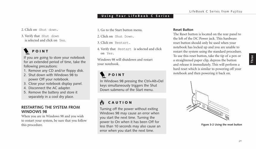
Reset ButtonThe Reset button is located on the rear panel tothe left of the DC Power jack. This hardwarereset button should only be used when yournotebook has locked up and you are unable torestart the system using the standard procedure.To use this reset button, take the tip of a pen ora straightened paper clip, depress the buttonand release it immediately. This will perform ahard reset which is similar to powering off yournotebook and then powering it back on.
2. Click on Shut down.
3. Verify that Shut downis selected and click on Yes .
RESTARTING THE SYSTEM FROMWINDOWS 98When you are in Windows 98 and you wish to restart your system, be sure that you followthis procedure.

S e c t i o n T h r e e
22
STATUS INDICATOR PANELThe Status Indicator panel is located in therecess just above the keyboard. (Figure 3-3.)The appropriate icon will appear to indicate the activity of the corresponding component in your notebook.
Power Indicator
The Power indicator tells you when the systemis operational. It is on steady when there ispower to your notebook, and blinks when thesystem is in Suspend mode. It goes off whenthe system has entered Save-to-Disk mode orhas been powered down by Windows 98 or the Power Button.
AC Adapter Indicator
The AC Adapter indicator tells you whether thesystem is operating on an AC or auto/airlineadapter, or the battery alone. The indicator isOn when either of the adapters is active and Offwhen power comes from the battery alone.
Figure 3-3 Status Indicator Panel
Power CD-ROM Drive Access
Hard Drive AccessAC Adapter BatteryLevel
PCCardSlot
IdentifierFloppy Disk Drive Access
NumLk
CapsLock
Scr LkBattery Charging
PC Card Access Indicator
Th
ree
U s i n g Y o u r L i f e B o o k C S e r i e sL i f e B o o k C S e r i e s f r o m F u j i t s u
23
If a battery is charging, the Power Adapterindicator is active regardless of whether yournotebook is On or Off. If there is no batterycharging, and your notebook is powered Off,then the AC Adapter indicator and the Battery indicators will all be Off.
Battery Indicator
The battery indicator shows whether or not theLithium ion battery is installed, and indicatesit's condition. (Figure 3-3.)
A small arrow icon (Battery Charging indica-tor) appears to the left of the Battery Levelindicator and above the number (Battery iden-tifier) if the battery is charging. The BatteryCharging indicator flashes if the battery is toohot or too cold to charge. (Figure 3-3.) TheBattery Charging indicators operate whetherthe notebook is Off or On.
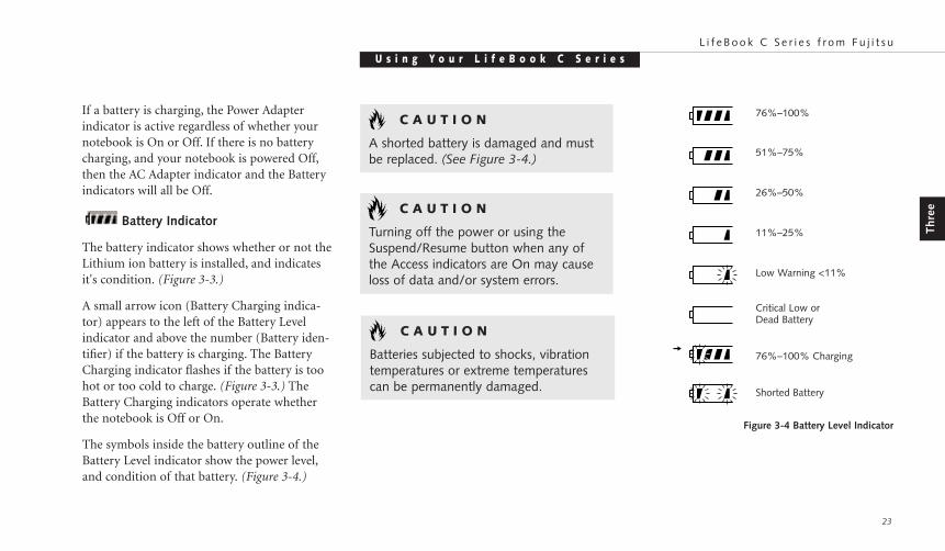
The symbols inside the battery outline of theBattery Level indicator show the power level,and condition of that battery. (Figure 3-4.)
C A U T I O N
A shorted battery is damaged and mustbe replaced. (See Figure 3-4.)
Figure 3-4 Battery Level Indicator
C A U T I O N
Turning off the power or using theSuspend/Resume button when any ofthe Access indicators are On may causeloss of data and/or system errors.
76%–100%
51%–75%
26%–50%
11%–25%
Low Warning <11%
Critical Low or Dead Battery
76%–100% Charging
Shorted Battery
C A U T I O N
Batteries subjected to shocks, vibrationtemperatures or extreme temperaturescan be permanently damaged.
To disable the CD automatic insertion function:
1. Save all data and close all applications.
2. Click on the Start button.
3. Point to Settings.
4. Click on the Control Panel. The controlpanel window will be displayed.
5. Double click on the System icon. The systemproperties dialogue box will be displayed.
6. Click on the Device Manager tab. The devicelist will be displayed.
7. Click on the + to the left of the CD-ROMicon. The CD-ROM drive manufacturer’sname and model will be displayed.
S e c t i o n T h r e e
24
P O I N T
The Windows 98 CD automatic insertionfunction will periodically check for aCD inserted in the drive, causing theCD-ROM Access indicator to flash. TheCD automatic insertion function allowsyour system to automatically start a CDas soon as it is inserted in the drive andthe tray is closed. It will begin playingan audio CD or will start an applicationif the CD includes an auto run file.
CD-ROM Drive Access Indicator
The CD-ROM Access indicator tells you thatthe CD-ROM drive is being accessed. TheCD-ROM Access indicator will flash whenthe software tries to access a CD even if no CD is inserted.
P O I N T
You can disable the CD automatic insertion function if you wish.
8. Double click on the CD-ROM drive manu-facturer’s name and model.
9. The CD-ROM drive manufacturer’s nameand model properties dialogue box willbe displayed.
10. Click on the Settings tab.
11. Click on the automatic insertionnotification box to turn it off.
12. Click on OK.
13. Click on Close in the system propertiesdialogue box.
14. Click on Yes in the system settingschange pop-up to restart the computer andactivate this change.
You can re-activate the function by repeating the process, except that step 11 will change thesetting to on.
Th
ree
U s i n g Y o u r L i f e B o o k C S e r i e sL i f e B o o k C S e r i e s f r o m F u j i t s u
25
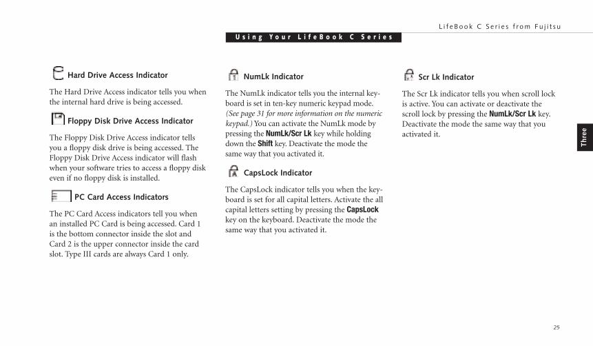
NumLk Indicator
The NumLk indicator tells you the internal key-board is set in ten-key numeric keypad mode.(See page 31 for more information on the numerickeypad.) You can activate the NumLk mode bypressing the NumLk/Scr Lk key while holdingdown the Shift key. Deactivate the mode thesame way that you activated it.
CapsLock Indicator
The CapsLock indicator tells you when the key-board is set for all capital letters. Activate the allcapital letters setting by pressing the CapsLockkey on the keyboard. Deactivate the mode thesame way that you activated it.
Hard Drive Access Indicator
The Hard Drive Access indicator tells you whenthe internal hard drive is being accessed.
Floppy Disk Drive Access Indicator
The Floppy Disk Drive Access indicator tellsyou a floppy disk drive is being accessed. TheFloppy Disk Drive Access indicator will flashwhen your software tries to access a floppy diskeven if no floppy disk is installed.
PC Card Access Indicators
The PC Card Access indicators tell you whenan installed PC Card is being accessed. Card 1is the bottom connector inside the slot andCard 2 is the upper connector inside the cardslot. Type III cards are always Card 1 only.
Scr Lk Indicator
The Scr Lk indicator tells you when scroll lockis active. You can activate or deactivate thescroll lock by pressing the NumLk/Scr Lk key.Deactivate the mode the same way that youactivated it.
S e c t i o n T h r e e
26
BATTERIESThe Lithium ion battery is rechargeable with anoperating time of up to 2.5 hours (C352) or 2hours (C360) depending on active power man-agement features and user activity levels. If theinternal Lithium ion Battery goes dead, youmust install the AC adapter or shut down andinstall a charged battery. (See page 107 for replacing the battery.)
The Lithium ion battery operating time maybecome shorter than the reference value if it isused under the following conditions:
■ When used at temperatures that exceed a lowof 5°C or a high of 35°C. High temperaturesnot only reduce charging efficiency, but canalso cause battery deterioration. (The Charg-ing icon on the Status Indicator panel willflash when you try to charge a battery that isoutside its operating temperature range.)
C A U T I O N
Actual battery life will vary basedon screen brightness, applications,features, power management settings,battery condition, and other customerpreferences. CD-ROM drive, hard drive,and modem usage may also have a significant impact on battery life.
■ The battery charging capacity is reduced as thebattery ages. If your battery is running lowquickly, you should replace it with a new one.
■ When using a high current device such as amodem, a LAN card, the CD-ROM drive, orthe hard drive frequently.
Using the AC adapter will conserve your batterywhen using a high current device such as amodem, a LAN card, the CD-ROM drive, orthe hard drive frequently.
C A U T I O N
Do not leave a faulty battery in yournotebook. It might damage your ACadapter, optional auto/airline adapter,another battery, or your notebook itself.It may also prevent operation of yournotebook by draining all available currentinto the bad battery.
C A U T I O N
Under federal, state or local law itmay be illegal to dispose of batteries byputting them in the trash. Please takecare of our environment and disposeof batteries properly. Check with yourlocal government authority for detailsregarding recycling or disposing ofold batteries. If you cannot find thisinformation elsewhere, contact yoursupport representative at 1-800-8FUJITSU(1-800-838-5487).
Th
ree
U s i n g Y o u r L i f e B o o k C S e r i e sL i f e B o o k C S e r i e s f r o m F u j i t s u
27
Shorted BatteriesIf your Status Indicator panel shows a shortedbattery, check the installation for that battery byremoving and re-installing it. If it still showsthat it is shorted, replace it with a new battery.
C A U T I O N
A shorted battery is damaged and mustbe replaced so that it does not damageanything else.
The Lithium ion battery is recharged internallyusing the AC adapter or auto/airline adapter.To recharge a battery:
■ Make sure the battery to be charged isinstalled in the battery bay of your notebookand the notebook is connected to apower source.
■ Make sure that the Battery Charging indica-tor to the left of the Battery Level indicatoris visible on the Status Indicator panel.
■ Make sure the percentage charge is showninside the Battery Level icon.(Figure 3-4 on page 23.)
Recharging the BatteryIf you want to check the condition of theLithium ion battery check the Battery Levelindicator located on the Status Indicator panel. This indicator changes as the battery level changes.
There is no memory effect on the Lithium ionbatteries, which means that you do not need todischarge them completely before recharging. Asingle fully discharged Lithium ion battery willcharge in approximately three (3) hours whenyour notebook is Off or in Suspend mode. Thecharging time will be significantly longer if yournotebook is in use when the battery is charging,(approximately nine (9) hours.)
C A U T I O N
Using heavy current devices such as LANcards or frequent CD-ROM accesses mayprevent charging completely.
C A U T I O N
When you are in Suspend mode theremust always be at least one power sourceactive. If you turn off the power withthe power button, or remove all powersources, battery, AC adapter or auto/airline adapter, while your notebook is inSuspend mode any data which has notbeen saved to the hard drive will be lost.
S e c t i o n T h r e e
28
Low Battery StateWhen the battery is running low, your note-book beeps about every 15 seconds and theBattery Level indicator flashes. If you do notrespond to the low battery alarm, the batterywill continue to discharge until it is too low tooperate. When this happens there will be a mul-tiple beep alarm, the Battery Level indicator willshow dead battery, and your notebook will gointo Suspend mode to try and protect your dataas long as possible. Your power managementsettings do not effect what happens at the deadbattery alarm level. Your notebook will go toSuspend mode. (Figure 3-4 on page 23.)
C A U T I O N
There is no guarantee that data will notbe lost once your notebook enters theDead Battery Suspend mode.
C A U T I O N
You may not be able to hear the audioalarms if the volume control is set toolow or is turned off by either hardware orsoftware but you will still be able to seethe Battery Level indicator flash.
When the low battery alarm occurs, you need tosave all your active data and put your notebookinto Suspend mode until you can provide a newpower source. You should provide this power assoon as possible. The new power source can bea charged battery or a power adapter, either ACor auto/airline.
Critical Low Battery Suspend mode shows onthe Status indicator just like the normalSuspend mode. Once you have providedpower, you will need to press the Suspend/-0Resume button to resume operation. In theSuspend mode, your data can be maintainedfor sometime. If a power source is not providedpromptly, the Power indicator will stop flashingand go out, and you will have lost the data thatwas not stored.
Once you provide power, you can continue touse your notebook while an adapter is chargingthe battery. However, this charges the batterymore slowly. If you want to charge the batteryquickly, put your notebook into Suspend Mode,or turn it off while the adapter is charging thebattery. (See Power Off on pages 20-21 for shutdown procedures.)
Once your notebook goes into Critical LowBattery Suspend mode, you will be unable toresume operation until you provide a source ofpower either from an AC adapter, an optionalauto/airline adapter, or a charged battery.

Th
ree
U s i n g Y o u r L i f e B o o k C S e r i e sL i f e B o o k C S e r i e s f r o m F u j i t s u
29
INTEGRATED ERGOTRAC POINTING DEVICEThe ErgoTrac pointing device is composed ofa short, comfortable, dish-shaped pointingdevice and two buttons located in front of thekeyboard. The ErgoTrac pointing device has the function of a mouse, and moves the cursoraround on the screen – up, down, left and right.A light pressure with the tip of your finger is allthat is required to operate the ErgoTrac. Themore pressure you use, the faster the cursor willmove. The second part of the ErgoTrac point-ing device – the buttons – function as mousebuttons, and the functions they performdepend on the application you are running.Figure 3-5 shows the position of the ErgoTracpointing device and buttons.
P O I N T
An external mouse can be connected to the PS/2 port on the right side of the notebook.
Figure 3-5 ErgoTrac pointing device
Right Button
Left Button
Cursor ControlCursor

ErgoTrac Pointing Device Control AdjustmentThe Mouse Properties in your WindowsControl Panel provides customization of yourErgoTrac pointing device. There are four (4)aspects of the ErgoTrac pointing device opera-tion which you can adjust.
S e c t i o n T h r e e
30
P O I N T
The interval between presses for doubleclicking, and other parameters of pointingand selecting, can be adjusted with theselections in the dialog box of the mouseicon in your Windows Control Panel.
DraggingDragging means moving the cursor over anobject, pressing the left button – and keeping itpressed – while moving the cursor to thedesired new location, then releasing the button.(Figure 3-7.)
ClickingClicking means pushing and releasing a button.To left-click move the screen cursor to the itemyou wish to select, press the left pointing devicebutton once, and then immediately release it. Toright-click, move the mouse cursor to the itemyou wish to select, press the right pointingdevice button once, and then immediatelyrelease it. (Figure 3-6.)
Double-ClickingDouble-clicking means following the precedingClicking procedure, but pressing the pointingdevice button twice in rapid succession.Double-clicking can only be done with the left button.
C A U T I O N
If the interval between clicks is too long,double-clicking will not be executed.
Figure 3-6 Clicking
Figure 3-7 Dragging
P O I N T
These instructions are for the right-hand-ed setting of the ErgoTrac. Changing toleft-handed in the Windows ControlPanel will reverse the functions of thetwo buttons.

Th
ree
U s i n g Y o u r L i f e B o o k C S e r i e sL i f e B o o k C S e r i e s f r o m F u j i t s u
31
■ Buttons – This lets you set up the buttons forright or left handed operation and set thetime interval for double clicking.
■ Pointers – This lets you set up the size andshape of the cursor for different functions.
■ Motion – This lets you set up the relation ofthe speed of motion of your finger to themotion of the cursor and to enable a trailingtail for the cursor arrow.
You may want to try practicing with differentadjustments until you find a combination thatis comfortable for you.
USING THE KEYBOARDYour notebook has an integral 87-key keyboard.(Figure 3-8.) The keys perform all the standardfunctions of a 101-key keyboard and alsoinclude Windows keys and other special func-tion keys. This section describes only those
items specific to your notebook. They are thenumeric keypad, the cursor keys, the functionkeys, the function extension key (Fn) and theWindows keys.
Numeric KeypadCertain keys on the keyboard perform dualfunctions as both standard character keys andnumeric keypad keys. Figure 3-8 highlightsthese keys. To switch into numeric keypadmode, press the NumLk/Scr Lk while holdingdown the Shift key. You can now enter numer-als 0 through 9, perform addition ( + ), sub-traction ( – ), multiplication ( * ), or division ( / ), and enter decimal points ( . ) using thekeys designated as ten-key function keys. Thekeys in the numeric keypad are marked on the front edge of the key to indicate their secondary functions.
To return these keys to their normal characterfunction, press the NumLk/Scr Lk while holdingdown the Shift key again.
P O I N T
When an external numeric keypad is con-nected to the notebook the NumLk modeenables the external keypad. The built-inkeyboard numeric keypad can be used byholding down the Fn key while using thedesignated keys.
Cursor KeysThe cursor keys are the four arrow keys on thekeyboard which allow you to move the cursorup Õ, down Ô, left Ó and right È as yourapplication allows.
P O I N T
The integrated ErgoTrac pointing deviceand/or external mouse are also used formoving the cursor around the screen.

S e c t i o n T h r e e
32
Function KeysYour notebook has 12 function keys, F1 throughF12. The functions assigned to these keys differfor each application. You should refer to yoursoftware documentation to find out how thesekeys are used. (Figure 3-8.)
Fn KeyThe Fn key provides extended functions for thenotebook and is always used in conjunctionwith another key. (Figure 3-8.)
Pressing F5 while holding down the Fn keyallows you to toggle between video compensa-tion and no compensation. (Video compensa-tion controls spacing on the display. When it isenabled, displays with less than 800 x 600 pixelresolution will still cover the entire screen.)
Pressing F10 while holding down the Fn keyallows you to change your selection of where tosend your display video. Each time you press thecombination of keys you will step to the nextchoice. The choices, in order, are: built-in dis-play panel only, external monitor only, or bothbuilt-in display panel and external monitor.
Figure 3-8 Keyboard
Function Keys Numeric Keypad
Fn Key Start Key Start Key Application Key Cursor Keys
Th
ree
U s i n g Y o u r L i f e B o o k C S e r i e sL i f e B o o k C S e r i e s f r o m F u j i t s u
33
Windows KeysYour notebook has three Windows keys, twoStart keys and an Application key. The Start keydisplays the Start menu. This is the same as thebutton on the toolbar which is typically at thebottom of your Windows 98 desktop. TheApplication key has the same function inWindows 98 as the right mouse button, it dis-plays the Shortcut menu for whatever item isselected. See your Windows 98 documentationfor additional information. (Figure 3-8.)
VOLUME CONTROLAll system and application functions have mul-tiple volume controls which interact with eachother. There is the hardware volume control onthe right side panel of your notebook. There isalso a volume control in the your operating system Sound Control panel and any otherapplication with sound.
Each setting source puts an upper limit on thevolume which can be set by the other sources.For example if the hardware volume control isturned all the way down, your software volume
C A U T I O N
The operating system volume settingsets the maximum volume level of thehardware volume control knob.
control settings have no effect. By the sametoken, if the operating system has the soundturned off, adjusting the hardware or otherapplication software volume settings will notproduce sound. One easy operating method isto use the hardware and operating system volume controls to set an upper limit on sound level and then make fine adjustmentswith other application software.
FLOPPY DISK DRIVEThe floppy disk drive is a 3.5" drive which canread and write on 1.44MB and 720KB floppydisks. Floppy disk format is controlled fromyour operating system. (See your softwaredocumentation for more information.)
Loading a Floppy DiskInsert a floppy disk into the floppy disk drive –shutter side first and label up – until the Ejectbutton pops out. (Figure 3-9.)
P O I N T
When there is no floppy disk in thedrive, the Eject button is flush with theright-side of your notebook.
S e c t i o n T h r e e
34
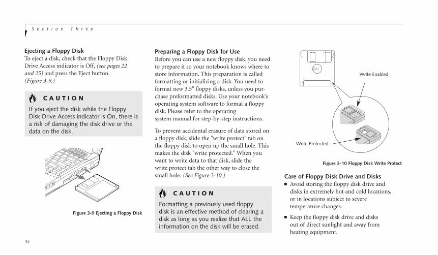
Ejecting a Floppy DiskTo eject a disk, check that the Floppy DiskDrive Access indicator is Off, (see pages 22 and 25) and press the Eject button.(Figure 3-9.)
C A U T I O N
Formatting a previously used floppydisk is an effective method of clearing adisk as long as you realize that ALL theinformation on the disk will be erased.
C A U T I O N
If you eject the disk while the FloppyDisk Drive Access indicator is On, there isa risk of damaging the disk drive or thedata on the disk.
Preparing a Floppy Disk for UseBefore you can use a new floppy disk, you needto prepare it so your notebook knows where tostore information. This preparation is calledformatting or initializing a disk. You need toformat new 3.5" floppy disks, unless you pur-chase preformatted disks. Use your notebook’soperating system software to format a floppydisk. Please refer to the operatingsystem manual for step-by-step instructions.
To prevent accidental erasure of data stored ona floppy disk, slide the "write protect" tab onthe floppy disk to open up the small hole. Thismakes the disk "write protected." When youwant to write data to that disk, slide the write protect tab the other way to close thesmall hole. (See Figure 3-10.)
Figure 3-9 Ejecting a Floppy Disk
Figure 3-10 Floppy Disk Write Protect
Write Enabled
Write Protected
Care of Floppy Disk Drive and Disks■ Avoid storing the floppy disk drive and
disks in extremely hot and cold locations,or in locations subject to severetemperature changes.
■ Keep the floppy disk drive and disksout of direct sunlight and away fromheating equipment.

Th
ree
U s i n g Y o u r L i f e B o o k C S e r i e sL i f e B o o k C S e r i e s f r o m F u j i t s u
35
C A U T I O N
Do not operate your CD-ROM driveunless your notebook is sitting on a flat surface. Using a CD when the driveis not level may damage the drive orprevent proper operation.
■ Avoid storing the floppy disk drive inlocations subject to shock and vibration.
■ Avoid using the floppy disk drive and disks in damp and dusty locations.
■ Never use the floppy disk drive with any liquid, metal, or other foreign matter insidethe floppy disk drive or disk.
■ Never store a floppy disk near a magnet ormagnetic field.
■ Never disassemble or dismantle your floppydisk drive. This may cause damage to yoursystem and will void your warranty.
Loading a CD■ Make sure there is power to your notebook.
■ Push, gently but firmly, and release the ejectbutton on the front of the CD-ROM drive toopen the CD-ROM holder tray, the tray willcome out a short distance. (See Figure 3-11.)
■ Gently pull the tray out until a CD-ROM canbe easily placed in the tray.
CD-ROM DRIVEThe CD-ROM drive is a 24x maximumCD-ROM reader.
Figure 3-11 Loading the CD-ROM Tray
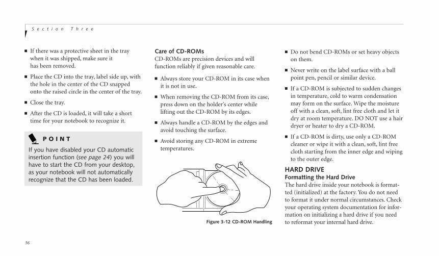
Care of CD-ROMsCD-ROMs are precision devices and willfunction reliably if given reasonable care.
■ Always store your CD-ROM in its case whenit is not in use.
■ When removing the CD-ROM from its case,press down on the holder’s center whilelifting out the CD-ROM by its edges.
■ Always handle a CD-ROM by the edges andavoid touching the surface.
■ Avoid storing any CD-ROM in extremetemperatures.
S e c t i o n T h r e e
36
■ If there was a protective sheet in the traywhen it was shipped, make sure ithas been removed.
■ Place the CD into the tray, label side up, withthe hole in the center of the CD snappedonto the raised circle in the center of the tray.
■ Close the tray.
■ After the CD is loaded, it will take a shorttime for your notebook to recognize it.
P O I N T
If you have disabled your CD automaticinsertion function (see page 24) you willhave to start the CD from your desktop,as your notebook will not automaticallyrecognize that the CD has been loaded.
■ Do not bend CD-ROMs or set heavy objectson them.
■ Never write on the label surface with a ballpoint pen, pencil or similar device.
■ If a CD-ROM is subjected to sudden changesin temperature, cold to warm condensationmay form on the surface. Wipe the moistureoff with a clean, soft, lint free cloth and let itdry at room temperature. DO NOT use a hairdryer or heater to dry a CD-ROM.
■ If a CD-ROM is dirty, use only a CD-ROMcleaner or wipe it with a clean, soft, lint freecloth starting from the inner edge and wipingto the outer edge.
HARD DRIVEFormatting the Hard DriveThe hard drive inside your notebook is format-ted (initialized) at the factory. You do not needto format it under normal circumstances. Checkyour operating system documentation for infor-mation on initializing a hard drive if you needto reformat your internal hard drive.Figure 3-12 CD-ROM Handling

Th
ree
U s i n g Y o u r L i f e B o o k C S e r i e sL i f e B o o k C S e r i e s f r o m F u j i t s u
37
C A U T I O N
The internal modems on all Fujitsunotebooks from Fujitsu PC Corporationare not qualified for use with telephone systems outside the United States andCanada and may not operate inother countries.
C A U T I O N
If you reformat the internal hard driveALL data including the operating system,applications software and data will beerased. Unless data is copied to floppydisks or other data storage media it willbe permanently lost. All software will beneed to be re-installed and data filesrestored from your back-up disks. See theoperating system manual for more infor-mation on backing-up your data files. Thefactory installed software, including theoperating system, can be restored fromthe Recovery CD-ROM which came inthe accessories box when you purchasedyour notebook. (See Recovery CD-ROMon page 142 for more information.) Anyapplication software which you have pur-chased and installed will have to be re-installed from the original source. Whendoing a recovery remember that you mustallocate space for the Save-to-Disk func-tion if you have it enabled. (See SettingUp Your Save-to-Disk File Allocation onpages 102-103 for more information.)
C A U T I O N
The internal modem is designed tothe ITU-T V.90 standard. Its maximumspeed of 53000bps is the highest allowedby FCC, and its actual connection ratedepends on the line conditions. Themaximum speed is 33600bps at upload.
C A U T I O N
The internal modem is not intended foruse with Digital PBX systems. Do notconnect the internal modem to a digitalPBX as it may cause serious damage tothe internal modem or your entire note-book. Consult your PBX manufacturer’sdocumentation for details. Some hotelshave digital PBX systems. Be sure to findout BEFORE you connect your modem.
INTERNAL MODEMYour internal modem is a 56K fax/data/voicemodem with v.90 support that is controlled byWindows 98, LapLink, or other software.

POWER MANAGEMENTYour LifeBook C Series has many features forconserving power. Some power savings featuresare automatic and have no user control, suchas those for the internal modem, while othersdepend on the parameters you set to best suityour operating conditions. Other power savingfeatures turn the display brightness down, limitthe use of high power devices, activate anappropriate power savings profile, and put yournotebook in Suspend mode when not actuallyperforming an operation. As with all mobile,battery-powered computers, there is a trade-offbetween performance and power savings.
Internal power management for your notebookmay be controlled from settings made in theBIOS setup utility, or from settings made inyour operating system.
Using the Suspend/Resume FeaturesWhen your notebook is active, the Power but-ton, (Figure 1-3 on page 5), can be used to man-ually put your notebook into Suspend mode.The Power button is located next to the Status
S e c t i o n T h r e e
38
Indicator panel above the keyboard of yournotebook. (Figure 3-13.) Push the Power but-ton, when your notebook is active but noAccess indicators are on and release the button(immediately). You will hear two short beepsand then your system will enter Suspend mode.
If your notebook is suspended, pushing thePower button will return your notebook toactive operation at the point where it went intosuspension. You can tell whether or not yoursystem is in Suspend mode by looking at thePower indicator. (See page 22.) If it is visibleand not flashing, your notebook is fully opera-tional. If it is visible and flashing, your note-book is in Suspend mode. If it is not visible, thepower is Off or your notebook is in Save-to-Disk mode. (See page 40.) When you receiveyour LifeBook C Series it will be set to thedefault in BIOS, which is Suspend mode.
P O I N T
You can also power Off your notebookby pressing the power button down for
P O I N T
Disabling the Suspend/Resume functionprevents it from being used to put yournotebook in Standby or Save-to-Diskmode. The resume function of the buttoncannot be disabled. (See the PowerMenu of the BIOS setup utility, pages91-92, for more information.)
Figure 3-13 The Power Button
four seconds when you are in the sus-pend mode. If you are not in suspendmode, you will need to press the powerbutton once quickly to enter suspendmode, in order to use this method.
Th
ree
U s i n g Y o u r L i f e B o o k C S e r i e sL i f e B o o k C S e r i e s f r o m F u j i t s u
39
C A U T I O N
The Standby or Save-to-Disk mode should not be used with certain PC Cards.Check your PC Card documentation formore information.
P O I N T
If your notebook is active when youenter the Standby or Save-to-Disk mode,changes to open files are not lost. Thefiles are left open and memory is keptactive during Standby mode or thememory is transferred to the internalhard drive during Save-to-Disk mode.
C A U T I O N
If you are running your notebook on battery power, be aware that the batterycontinues to discharge while your note-book is in Suspend mode, though not asfast as when fully operational. With afully charged internal Lithium ion batterythe suspend mode will maintain your status for 24 hours or more.
■ Pressing the Power button when your systemis in the On state.
■ Selecting Standby from the Windows ShutDown menu.
■ Timing out from lack of activity.
■ Battery level reaching the Dead BatteryWarning condition.
Your notebook’s system memory typicallystores the file(s) on which you are working,the open application(s) and any other datarequired to support the operation(s) inprogress. When you resume operation fromStandby mode, it returns to the point in theoperation where it left off. You must use thePower button to resume operation, and theremust be an adequate power source available,or your notebook will not resume.
Standby ModeStandby mode, in Windows 98, saves the con-tents of your notebook’s system memory dur-ing periods of inactivity by maintaining powerto critical parts while turning off the CPU, thedisplay, the hard drive and all of the otherinternal components except those necessary tomaintain system memory, recognize the Powerbutton and restart. Your notebook can be put inSuspend mode by:

S e c t i o n T h r e e
40
Using the Power Button to Perform Save-to-DiskWhen your notebook is active, the Power but-ton, (Figure 3-13.), can be used to manually putyour notebook into Save-To-Disk mode.However, you must first enable Save-to-Diskmode by enabling Save-to-Disk mode in theBIOS Setup utility Power menu. (See pages 85-89 for more information on the Power menu ofthe BIOS Setup utility.)
Push the Power button, when your notebookis active but no Access indicators are on andrelease the button (immediately). You willhear two short beeps and then your systemwill flash the Save-to-Disk screen, and enterSave-to-Disk mode.
C A U T I O N
Loss of all power sources, including batteries, while in the Standby mode willcause lost data and inability to return to operation with the Power button.
P O I N T
If power is lost during Save-to-Disk modethe data will be retrieved automatically assoon as power is returned.
If your notebook is in Save-to-Disk mode,pushing the Power button will return yournotebook to active operation at the point whereit went into Save-to-Disk mode. You can tellwhether or not your system is in Save-to-Diskmode by looking at the Power indicator. (Seepage 22.) If it is visible and not flashing, yournotebook is fully operational. If it is visible andflashing, your notebook is in Suspend mode.If it is not visible, the power is Off or yournotebook is in Save-to-Disk mode.
P O I N T
When PC Cards or external devices are in use, Save-to-Disk mode cannot returnto the exact state prior to suspension,because all of the peripheral devices willbe re-initialized when the system restarts.
P O I N T
The main advantage of using the Save-to-Disk function is that power is not required to maintain your data. This is particularly important if you will beleaving your notebook in a suspendedstate for a prolonged period of time. Thedrawback of using Save-to-Disk mode is that it lengthens the power down andpower up sequences and resets peripheral devices.
Th
ree
U s i n g Y o u r L i f e B o o k C S e r i e sL i f e B o o k C S e r i e s f r o m F u j i t s u
41
P O I N T
Save-to-Disk mode requires allocating asignificant amount of hard drive capacityfor saving all system memory, whichreduces your usable disk space. Whenyou purchase your notebook it will havespace allocated for the memory installed.If you increase the system memory witha memory Upgrade module, you willneed to change the size of your Save-to-Disk allocation. Use the PHDISK Utility toincrease the size of the Save-to-Disk file,SAVE2DSK.BIN. (Refer to Setting UpYour Save-to-Disk File Allocation on
pages 102-103 for more information.)If you need help contact your supportrepresentative for recommendations.
Save-to-Disk ModeThe Save-to-Disk function saves the contents ofthe notebook’s system memory to the harddrive as a part of the Suspend/Resume func-tion. Your notebook is setup to perform thisfunction in one way and can be configuredthrough the system BIOS to do it in other ways.
Default Method for using Save-to Disk Mode:■ Press the Fn key together with the
Suspend/Resume button when activating theSuspend mode. The Save-to-Disk pop-upwill appear on your screen, simply wait untilit has finished and your notebook will gointo Save-to-Disk mode.
C A U T I O N
Be sure you know which settings areactive for the Power Button before youuse it; misuse can result in data loss. (Seethe Power Menu of the BIOS setup utility,pages 85-92, for more information.)
Customer configured BIOS methods:■ Press the Power Button until acknowledged
with Save-to-Disk mode enabled from thePower menu of the BIOS setup utility.
■ Select Standby from the Windows ShutDown menu with Save-to-Disk enabled bythe BIOS Setup Utility.
■ Time out from lack of activity with Save-To-Disk mode enabled from the Power Savingsmenu of the BIOS setup utility.
Your notebook’s system memory typically storesthe file(s) on which you are working, the openapplication(s) and any other data required tosupport the operation(s) in progress. When theSave-to-Disk function is activated your notebooksaves the contents of the system memory to a fileon the internal hard drive, and then automatical-ly shuts off power to your notebook. When youresume operation by pressing the Power button,you return to the point in the operationwhere you left off, before going intoSave-to-Disk mode.
P O I N T
Save-to-Disk mode will not operatewhen Resume On Modem Ring hasbeen selected in the BIOS.
S e c t i o n T h r e e
42
Video TimeoutThe Video Timeout is one of the power man-agement parameters which saves power byturning off the display if there is no keyboardor pointer activity for the user selected timeoutperiod. Any keyboard or pointer activity willcause the display to restart automatically. Thisfeature is independent of the Power button.This parameter is enabled and disabled in theBIOS setup utility. (See pages 85-86.)
Hard Disk TimeoutThe Hard Disk Timeout is one of the powermanagement parameters which saves power by turning off the hard drive if there is no harddrive access for the timeout period which hasbeen set in the BIOS setup utility. (See pages85-86.) Any attempt to access the hard drive willcause the hard drive to restart automatically.This feature is independent of the Suspend/Resume button. This parameter is enabled and disabled in the BIOS setup utility.
Idle ModeIdle mode is one of the power managementparameters. When Idle mode is enabled theCPU is put into low-speed operation whenthere is no activity (keystroke, pointer action,sound generation, video display change,modem transmission or reception, etc.) onyour notebook for 16 seconds. Any activitywill cause the normal operation to restart|automatically. This feature is independentof the Suspend/Resume modes. This parameteris enabled and disabled in the BIOSsetup utility. (See pages 85-86.)
Standby ModeStandby mode is one of the power managementparameters. When Standby mode is activated,your notebook puts the CPU in low-speedoperation, shuts off the display and turns offthe hard drive when there is no activity (key-stroke, pointer action, sound generation, videodisplay change, modem transmission or recep-tion, etc.) on your notebook for the user select-ed time-out period. (See page 80.) Any activitywill cause your notebook to return to normaloperation automatically. This feature is inde-pendent of the Power button. This parameter isenabled and disabled in the BIOS setup utility.
P O I N T
Windows 98 has its own integratedpower management features that includethe functionality of those listed above.(Idle and Standby Mode)
P O I N T
By holding down the Fn key while pressing the Power Button, it is possibleto enter Save-to-Disk mode withoutenabling it in the BIOS Setup utility.
Th
ree
U s i n g Y o u r L i f e B o o k C S e r i e sL i f e B o o k C S e r i e s f r o m F u j i t s u
43
Windows Power Management Control PanelsThe Power Management icon in the Windows98 Control Panel allows you to configure someof the power management settings that arenormally controlled by the BIOS. For instance,you can set timeout values in the PowerManagement Control Panel for turning off thedisplay and for turning off hard disks. You canspecify these timeout values based on whetheryou are running on batteries or AC.
DATA SECURITYYour LifeBook C Series has a built-in hardwarecontrol password security feature that allowsyou to protect the data stored in the notebookfrom unauthorized access. Your operatingsystem and some applications have softwarecontrol password security features that allow youto protect all or portions of the data stored in thenotebook from unauthorized access.
C A U T I O N
Make sure you memorize your passwords,both hardware and software. If youforget, you may not be able to use thenotebook, and you will have to contactyour service provider and arrange tohave them reset the hardware systempassword. See your software documen-tation for what to do if you forget yoursoftware security password(s).
C A U T I O N
Software security feature passwords maynot be the same as the hardware securitypasswords. Be sure you know which features are controlled from softwareand which from hardware or you maylock yourself out of your own data orlock up your hardware and not be ableto operate your notebook.
Hardware Data Security FeaturesWhen you are using your notebook's built-inhardware control password to gain access to thenotebook the actual password will not appearon the screen. This is a safety precaution. Thehardware control security parameters are setfrom the BIOS setup utility. (See Security Menuon pages 80-84 for more information on settingand clearing passwords and enabling and disabling built-in security features.)
Software Data Security FeaturesThe operating system and some applicationshave security features that are independent ofthe built-in hardware protection features thatare controlled from the BIOS. See your softwaredocumentation for more information aboutthese features.
S e c t i o n T h r e e
44
McAfee VirusScanRunning your McAfee VirusScan program after loading data or programs from a floppydisk, CD-ROM or modem data transfer is aprecaution that will protect the data on yourhard drive from contamination or destruction.See your VirusScan online help screens forinformation on how and when to run this program. (Located in the Service and SupportSoftware folder.)
PC DoctorPC Doctor by Watergate Software is primarilyfor use by your support representative whenhelping you with trouble shooting. (See page119 for more information.) (Located in theService and Support Software folder.)
PRE-INSTALLED SOFTWAREYour LifeBook C Series comes with pre-installed software for playing audio and videofiles of various formats. In addition there is filetransfer and virus protection software.
All of the pre-installed software can be accessedfrom the Program folder of the Windows 98Start menu or the following folders above theProgram folder in the Start menu: SystemManagement Software, CommunicationsSoftware, Internet Software, Multi-mediaSoftware, Service and Support Software, andBusiness Software.
LapLinkLapLink by Traveling Software provides directfile transfers to other computers; data transfersvia internal modem, a PC Card modem, a serial cable, or a parallel cable (cables are notincluded). See the LapLink online help screensfor operating instructions. (Located in theCommunications Software folder.)
Quicken 99 BasicQuicken 99 Basic by Intuit is a personal moneymanagement program. It has features such asportfolio management, account registries, on-line banking, and bill paying features. (Locatedin the Business Software folder.)
Microsoft WorksMicrosoft Works is a suite of software containingthe basic tools to write letters and reports, trackfamily and friends with address books, managehome finances, and create a home inventory.(Located in the Business Software folder.)
ESS AudioRack™
The control of the AudioRack player software(AudioRack32) resembles the front panels ofa rack of stereo equipment and is operated inmuch the same way. There is also AudioRackrecorder software (AudioRecorder). Onlinehelp screens are accessible from the AudioDrivepanel of AudioRack32, click on the Help buttonfor more information. In the AudioRecorderdialog box, click on Help in the top taskbar.

U s i n g Y o u r L i f e B o o k C S e r i e sL i f e B o o k C S e r i e s f r o m F u j i t s u
45
In AudioRack32 the AudioDrive panel lets you turn on and off the available functions.When you left-click on a button it will activate.When a function is active, its button on theAudioDrive shows a green dot and its controlpanel is in the equipment rack. When it is offthe dot on the button is black and the controlpanel is not in the rack. You activate a slider orknob on a control panel by dragging it. Thefunctions available are DAT (Digital Audio Tapeplayer), 3D (3D-Stereo sound control), MIDI,Mixer and CD (Audio CD player).
Th
ree
P O I N T
Your LIfeBook C Series does not supportLCD Backlighting control or CPU Clockcontrol, these options are not selectablein the Power Control tab of PMSet 98.
P O I N T
For maximum frequency response andbandwidth, leave the graphic equalizerlevels at the mid-point (zero level). Tocustomize the frequency response toyour personal taste, adjust accordingly.
C A U T I O N
The ESS AudioRack volume settings set the maximum volume level of thehardware volume control knob forthat function.
C A U T I O N
If you use a speakerphone function, besure that the microphone setting in theESS AudioRack is disabled.
PMSet 98PMSet 98 is a power management applicationwhich allows you to monitor battery status.(Located in the System Management Software folder.)
Adobe® Acrobat® ReaderThe Adobe Acrobat Reader allows you to view,navigate, and print PDF files across all majorcomputing platforms. (Located in the Serviceand Support Software folder.)
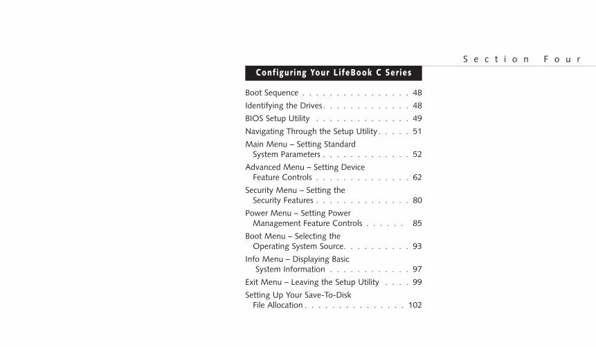
Configuring Your LifeBook C SeriesS e c t i o n F o u r
Boot Sequence . . . . . . . . . . . . . . . . 48
Identifying the Drives . . . . . . . . . . . . . 48
BIOS Setup Utility . . . . . . . . . . . . . . 49
Navigating Through the Setup Utility . . . . . 51
Main Menu – Setting Standard System Parameters . . . . . . . . . . . . . 52
Advanced Menu – Setting Device Feature Controls . . . . . . . . . . . . . . 62
Security Menu – Setting the Security Features . . . . . . . . . . . . . . 80
Power Menu – Setting Power Management Feature Controls . . . . . . 85
Boot Menu – Selecting the Operating System Source. . . . . . . . . . 93
Info Menu – Displaying BasicSystem Information . . . . . . . . . . . . 97
Exit Menu – Leaving the Setup Utility . . . . 99
Setting Up Your Save-To-Disk File Allocation . . . . . . . . . . . . . . . 102
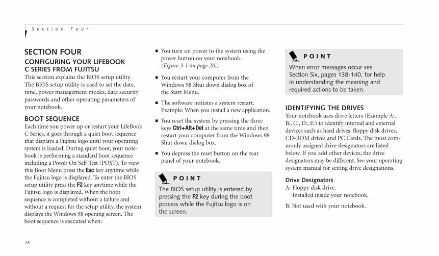
S e c t i o n F o u r
48
SECTION FOURCONFIGURING YOUR LIFEBOOKC SERIES FROM FUJITSUThis section explains the BIOS setup utility.The BIOS setup utility is used to set the date,time, power management modes, data securitypasswords and other operating parameters ofyour notebook.
BOOT SEQUENCEEach time you power up or restart your LifeBookC Series, it goes through a quiet boot sequencethat displays a Fujitsu logo until your operatingsystem is loaded. During quiet boot, your note-book is performing a standard boot sequenceincluding a Power On Self Test (POST). To viewthis Boot Menu press the Esc key anytime whilethe Fujitsu logo is displayed. To enter the BIOSsetup utility press the F2 key anytime while theFujitsu logo is displayed. When the bootsequence is completed without a failure andwithout a request for the setup utility, the systemdisplays the Windows 98 opening screen. Theboot sequence is executed when:
IDENTIFYING THE DRIVESYour notebook uses drive letters (Example A:,B:, C:, D:, E:) to identify internal and externaldevices such as hard drives, floppy disk drives,CD-ROM drives and PC Cards. The most com-monly assigned drive designators are listedbelow. If you add other devices, the drivedesignators may be different. See your operatingsystem manual for setting drive designations.
Drive DesignatorsA: Floppy disk drive.
Installed inside your notebook.
B: Not used with your notebook.
P O I N T
The BIOS setup utility is entered bypressing the F2 key during the bootprocess while the Fujitsu logo is onthe screen.
■ You turn on power to the system using thepower button on your notebook.(Figure 3-1 on page 20.)
■ You restart your computer from theWindows 98 Shut down dialog box ofthe Start Menu.
■ The software initiates a system restart.Example: When you install a new application.
■ You reset the system by pressing the threekeys Ctrl+Alt+Del at the same time and thenrestart your computer from the Windows 98Shut down dialog box.
■ You depress the reset button on the rearpanel of your notebook.
P O I N T
When error messages occur seeSection Six, pages 138-140, for help in understanding the meaning andrequired actions to be taken.

Fou
r
C o n f i g u r i n g Y o u r L i f e B o o k C S e r i e sL i f e B o o k C S e r i e s f r o m F u j i t s u
49
C: Hard drive.Installed inside your notebook.
D: CD-ROM drive.Installed inside your notebook.
BIOS SETUP UTILITYThe BIOS setup utility is a program that setsthe operating environment for your notebook.It is referred to in this publication as the setuputility. Normally, there is no need to change theenvironment, it is set at the factory for normaloperating conditions.
The setup utility configures:
■ Standard system parameters, such as dateand time.
■ Device control feature parameters, such asI/O addresses and boot devices.
■ Power Management parameters that help toconserve your notebook’s batteries.
■ System Data Security feature parameters,such as passwords.
You will only have to change the utility settingsif you want to:
■ Change the date or time. (You can alsodo this without entering the setup utility,through your operating system. See youroperating system manual.)
■ Change the primary boot device.
■ Change the power management parameter settings. (Can also be changed inthe operating system control panel.)
■ Change a port address or other parameter.
■ Change an audio parameter setting.
■ Change the selection of whether to use thebuilt-in display, an external monitor or both.(Can also be changed in the operating systemcontrol panel.)
■ Change the system data security settings.
Routinely Entering the Setup UtilityYou can enter the setup utility whenever youturn on or reset the system. To do this:
1. Allow the system to start booting.
2. As soon as the Fujitsu logo appears on thescreen, press the F2 key.
3. The Main menu of the setup utility thenappears with the current settings of theparameters displayed.
4. If you wish to go to one of the other setupmenus, press the Ó or the È key to find themenu you require.
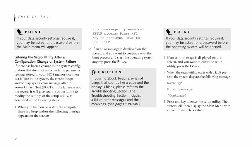
S e c t i o n F o u r
50
Error message - please runSETUP program Press <F1>key to continue, <F2> torun SETUP
2. If an error message is displayed on thescreen, and you want to continue with theboot process and start the operating systemanyway, press the F1 key.
P O I N T
If your data security settings require it,you may be asked for a password beforethe operating system will be opened.
P O I N T
If your data security settings require it,you may be asked for a password beforethe Main menu will appear.
C A U T I O N
If your notebook beeps a series of beeps that sounds like a code and thedisplay is blank, please refer to theTroubleshooting Section. TheTroubleshooting Section includesa list of error messages and theirmeanings. (See pages 138-140.)
3. If an error message is displayed on thescreen, and you want to enter the setuputility, press the F2 key.
4. When the setup utility starts with a fault pre-sent, the system displays the following message:
Warning!
Error message
[Continue]
5. Press any key to enter the setup utility. Thesystem will then display the Main Menu withcurrent parameters values.
Entering the Setup Utility After aConfiguration Change or System FailureIf there has been a change in the system config-uration that does not agree with the parametersettings stored in your BIOS memory, or thereis a failure in the system, the system beepsand/or displays an error message after thePower On Self Test (POST). If the failure is nottoo severe, it will give you the opportunity tomodify the settings of the setup utility, asdescribed in the following steps:
1. When you turn on or restart the computerthere is a beep and/or the following messageappears on the screen:
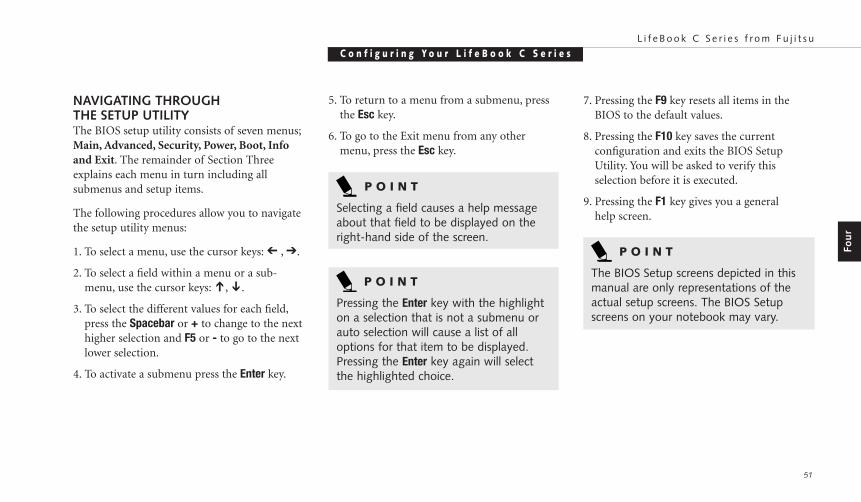
Fou
r
C o n f i g u r i n g Y o u r L i f e B o o k C S e r i e sL i f e B o o k C S e r i e s f r o m F u j i t s u
51
NAVIGATING THROUGHTHE SETUP UTILITYThe BIOS setup utility consists of seven menus;Main, Advanced, Security, Power, Boot, Infoand Exit. The remainder of Section Threeexplains each menu in turn including allsubmenus and setup items.
The following procedures allow you to navigatethe setup utility menus:
1. To select a menu, use the cursor keys: Ó , È.
2. To select a field within a menu or a sub-menu, use the cursor keys: Õ, Ô.
3. To select the different values for each field,press the Spacebar or + to change to the nexthigher selection and F5 or - to go to the nextlower selection.
4. To activate a submenu press the Enter key.
P O I N T
Selecting a field causes a help messageabout that field to be displayed on theright-hand side of the screen.
P O I N T
Pressing the Enter key with the highlighton a selection that is not a submenu orauto selection will cause a list of alloptions for that item to be displayed.Pressing the Enter key again will selectthe highlighted choice.
7. Pressing the F9 key resets all items in theBIOS to the default values.
8. Pressing the F10 key saves the currentconfiguration and exits the BIOS SetupUtility. You will be asked to verify thisselection before it is executed.
9. Pressing the F1 key gives you a generalhelp screen.
5. To return to a menu from a submenu, pressthe Esc key.
6. To go to the Exit menu from any othermenu, press the Esc key.
P O I N T
The BIOS Setup screens depicted in thismanual are only representations of theactual setup screens. The BIOS Setupscreens on your notebook may vary.
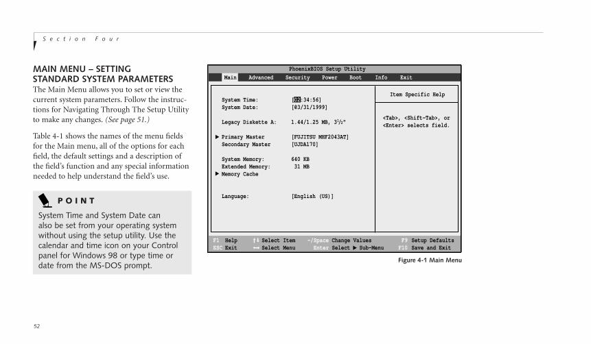
S e c t i o n F o u r
52
PhoenixBIOS Setup Utility
F1 HelpESC Exit
Select ItemSelect Menu
-/Space Change Values Enter Select Sub-Menu
F9 Setup Defaults F10 Save and Exit
▲
Main Advanced Security Power Boot Info Exit
Item Specific Help
<Tab>, <Shift-Tab>, or<Enter> selects field.
▲
System Time: [02:34:56]System Date: [03/31/1999]
Legacy Diskette A: 1.44/1.25 MB, 31/2"
Primary Master [FUJITSU MHF2043AT]Secondary Master [UJDA170]
System Memory: 640 KBExtended Memory: 31 MBMemory Cache
Language: [English (US)]
▲
Figure 4-1 Main Menu
MAIN MENU – SETTINGSTANDARD SYSTEM PARAMETERSThe Main Menu allows you to set or view thecurrent system parameters. Follow the instruc-tions for Navigating Through The Setup Utilityto make any changes. (See page 51.)
Table 4-1 shows the names of the menu fieldsfor the Main menu, all of the options for eachfield, the default settings and a description ofthe field’s function and any special informationneeded to help understand the field’s use.
P O I N T
System Time and System Date canalso be set from your operating systemwithout using the setup utility. Use thecalendar and time icon on your Controlpanel for Windows 98 or type time ordate from the MS-DOS prompt.
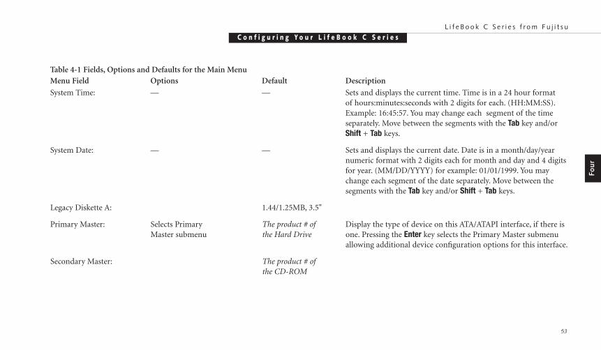
C o n f i g u r i n g Y o u r L i f e B o o k C S e r i e sL i f e B o o k C S e r i e s f r o m F u j i t s u
53
Menu Field Options Default Description
System Time: — — Sets and displays the current time. Time is in a 24 hour format of hours:minutes:seconds with 2 digits for each. (HH:MM:SS).Example: 16:45:57. You may change each segment of the time separately. Move between the segments with the Tab key and/or Shift + Tab keys.
System Date: — — Sets and displays the current date. Date is in a month/day/yearnumeric format with 2 digits each for month and day and 4 digitsfor year. (MM/DD/YYYY) for example: 01/01/1999. You maychange each segment of the date separately. Move between thesegments with the Tab key and/or Shift + Tab keys.
Legacy Diskette A: 1.44/1.25MB, 3.5"
Primary Master: Selects Primary The product # of Display the type of device on this ATA/ATAPI interface, if there is Master submenu the Hard Drive one. Pressing the Enter key selects the Primary Master submenu
allowing additional device configuration options for this interface.
Secondary Master: The product # ofthe CD-ROM
Fou
r
Table 4-1 Fields, Options and Defaults for the Main Menu
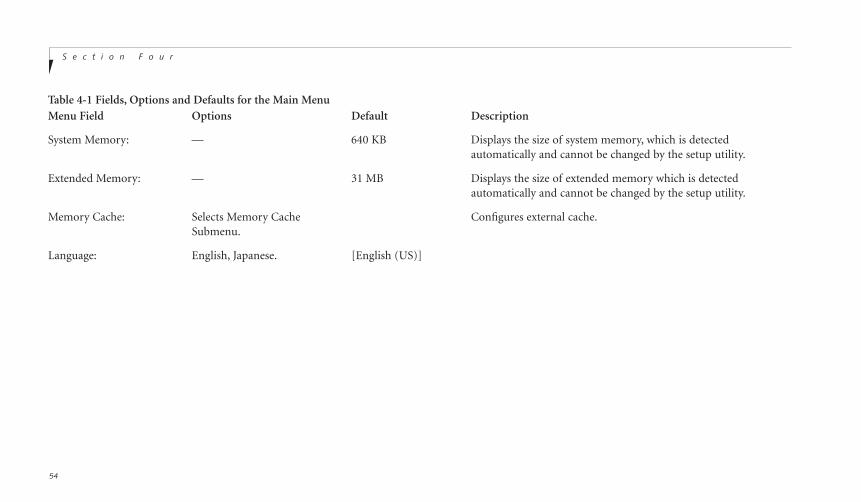
S e c t i o n F o u r
54
Table 4-1 Fields, Options and Defaults for the Main Menu
System Memory: — 640 KB Displays the size of system memory, which is detectedautomatically and cannot be changed by the setup utility.
Extended Memory: — 31 MB Displays the size of extended memory which is detectedautomatically and cannot be changed by the setup utility.
Memory Cache: Selects Memory Cache Configures external cache.Submenu.
Language: English, Japanese. [English (US)]
Menu Field Options Default Description

Fou
r
C o n f i g u r i n g Y o u r L i f e B o o k C S e r i e sL i f e B o o k C S e r i e s f r o m F u j i t s u
55
Primary Master – SubmenuThe Primary Master submenu is for the inter-nal hard drive. The drive type is displayed onthis menu as well as the Main menu. Your note-book auto-senses the characteristics of theHard Disk Drive installed. You will not need to modify these settings, they are displayed foryour reference. (See page 51.)
Table 4-2 shows the names of the menu fieldsfor the Primary Master submenu, all of theoptions for each field, the default settings anda description of the field’s function and anyspecial information needed to help understandthe field’s use.
Note – actual hard drive label shown may vary.
PhoenixBIOS Setup Utility
F1 HelpESC Exit
Select ItemSelect Menu
-/SpaceEnter
F9 Setup DefaultsF10 Save and Exit
Change ValuesSelect Sub-Menu
Main
Item Specific Help
User = you enterparameters of hard-diskdrive installed at thisconnection.Auto = autotypesATA/ATAPI driveinstalled here.CD-ROM = a CD-ROMdrive is installed here.
Primary Master [UJDA170]
Type: [Auto]Cylinders: [8944]Heads: [15]Sectors: [63]Maximum Capacity: 4327 MB
Multi-Sector Transfers: [16 Sectors]LBA Mode Control: [Enabled]Transfer Mode: [Fast PIO 4]Ultra DMA Mode: [Mode 2]
▲
Figure 4-2 Primary Master Submenu
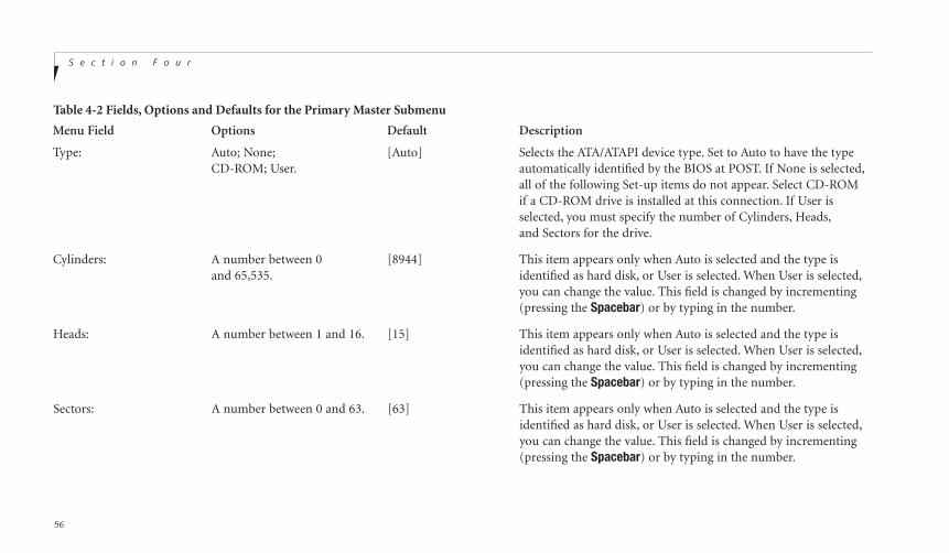
S e c t i o n F o u r
56
Menu Field Options Default Description
Type: Auto; None; [Auto] Selects the ATA/ATAPI device type. Set to Auto to have the type CD-ROM; User. automatically identified by the BIOS at POST. If None is selected,
all of the following Set-up items do not appear. Select CD-ROMif a CD-ROM drive is installed at this connection. If User is selected, you must specify the number of Cylinders, Heads,and Sectors for the drive.
Cylinders: A number between 0 [8944] This item appears only when Auto is selected and the type is and 65,535. identified as hard disk, or User is selected. When User is selected,
you can change the value. This field is changed by incrementing (pressing the Spacebar) or by typing in the number.
Heads: A number between 1 and 16. [15] This item appears only when Auto is selected and the type is identified as hard disk, or User is selected. When User is selected,you can change the value. This field is changed by incrementing (pressing the Spacebar) or by typing in the number.
Sectors: A number between 0 and 63. [63] This item appears only when Auto is selected and the type is identified as hard disk, or User is selected. When User is selected,you can change the value. This field is changed by incrementing (pressing the Spacebar) or by typing in the number.
Table 4-2 Fields, Options and Defaults for the Primary Master Submenu

C o n f i g u r i n g Y o u r L i f e B o o k C S e r i e sL i f e B o o k C S e r i e s f r o m F u j i t s u
57
Menu Field Options Default Description
Maximum Capacity: Display only. — Displays the maximum capacity of the drive calculated from the parameters of the hard disk when Auto is selected and the type is identified as hard disk, or User is selected.
Multi-Sector Transfers: Disabled; 2; 4; 8; 16. 16 Sectors Specify the number of sectors per block for multiple sector MAX 32; MAX 64; MAX 128. transfer. MAX refers to the size the disk returns when required.
This option cannot be changed when Auto is selected.
LBA Mode Control: Enabled; Disabled. Enabled Enables or disables logical Block Addressing in place of Cylinder,Head, Sector addressing. This option cannot be changed when Auto is selected.
Transfer Mode: Standard, Fast PIO 1; Fast PIO 2; Fast PIO 4/DMA Selects the method for moving data to/from the drive. Autotype Fast PIO 3; Fast PIO 4; the drive to select the optimum transfer mode. This option Fast PIO 3 / DMA; cannot be changed when Auto is selected.Fast PIO 4 / DMA.
Ultra DMA Mode: Disabled; Mode 0; Disabled Selects the method for moving data to/from the drive. Autotype Mode 1; Mode 2. the drive to select the optimum transfer mode. This option
cannot be changed when Auto is selected.
Fou
r
Table 4-2 Fields, Options and Defaults for the Primary Master Submenu

S e c t i o n F o u r
58
Secondary Master – SubmenuThe Primary Master submenu is for the internalhard drive. The drive type is displayed on thismenu as well as the Main menu. Your notebookauto-senses the characteristics of the Hard DiskDrive installed. You will not need to modifythese settings, they are displayed for yourreference. (See page 51.)
Table 4-3 shows the names of the menu fieldsfor the Secondary Master submenu, all of theoptions for each field, the default settings anda description of the field’s function and anyspecial information needed to help understandthe field’s use.
Note – actual hard drive label shown may vary.
Figure 4-3 Secondary Master Submenu
PhoenixBIOS Setup Utility
F1 HelpESC Exit
Select ItemSelect Menu
-/SpaceEnter
F9 Setup DefaultsF10 Save and Exit
Change ValuesSelect Sub-Menu
Main
Item Specific Help
User = you enterparameters of hard-diskdrive installed at thisconnection.Auto = autotypesATA/ATAPI driveinstalled here.CD-ROM = a CD-ROMdrive is installed here.
Primary Master [UJDA170]
Type: [Auto]
Multi-Sector Transfers: [Disabled]LBA Mode Control: [Disabled]Transfer Mode: [Fast PIO 4 DMA]Ultra DMA Mode: [Disabled]
▲
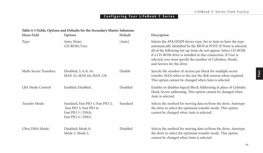
C o n f i g u r i n g Y o u r L i f e B o o k C S e r i e sL i f e B o o k C S e r i e s f r o m F u j i t s u
59
Menu Field Options Default Description
Type: Auto; None; [Auto] Selects the ATA/ATAPI device type. Set to Auto to have the type CD-ROM; User. automatically identified by the BIOS at POST. If None is selected,
all of the following Set-up items do not appear. Select CD-ROMif a CD-ROM drive is installed at this connection. If User is selected, you must specify the number of Cylinders, Heads,and Sectors for the drive.
Multi-Sector Transfers: Disabled; 2; 4; 8; 16. Disable Specify the number of sectors per block for multiple sector MAX 32; MAX 64; MAX 128. transfer. MAX refers to the size the disk returns when required.
This option cannot be changed when Auto is selected.
LBA Mode Control: Enabled; Disabled. Disabled Enables or disables logical Block Addressing in place of Cylinder,Head, Sector addressing. This option cannot be changed when Auto is selected.
Transfer Mode: Standard, Fast PIO 1; Fast PIO 2; Standard Selects the method for moving data to/from the drive. Autotype Fast PIO 3; Fast PIO 4; the drive to select the optimum transfer mode. This option
Fast PIO 3 / DMA; cannot be changed when Auto is selected.Fast PIO 4 / DMA.
Ultra DMA Mode: Disabled; Mode 0; Disabled Selects the method for moving data to/from the drive. Autotype Mode 1; Mode 2. the drive to select the optimum transfer mode. This option
cannot be changed when Auto is selected.
Fou
r
Table 4-3 Fields, Options and Defaults for the Secondary Master Submenu
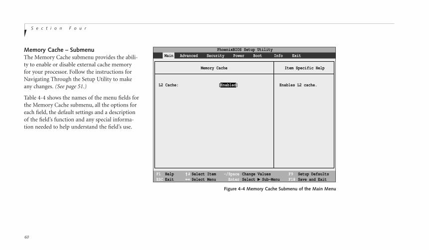
S e c t i o n F o u r
60
Memory Cache – SubmenuThe Memory Cache submenu provides the abili-ty to enable or disable external cache memoryfor your processor. Follow the instructions forNavigating Through the Setup Utility to makeany changes. (See page 51.)
Table 4-4 shows the names of the menu fields forthe Memory Cache submenu, all the options foreach field, the default settings and a descriptionof the field’s function and any special informa-tion needed to help understand the field’s use.
PhoenixBIOS Setup Utility
F1 HelpESC Exit
Select ItemSelect Menu
-/SpaceEnter
F9 Setup DefaultsF10 Save and Exit
Change ValuesSelect Sub-Menu
▲
Main Advanced Security Power Boot Info Exit
Item Specific Help
Enables L2 cache.
Memory Cache
L2 Cache: [Enabled]
Figure 4-4 Memory Cache Submenu of the Main Menu
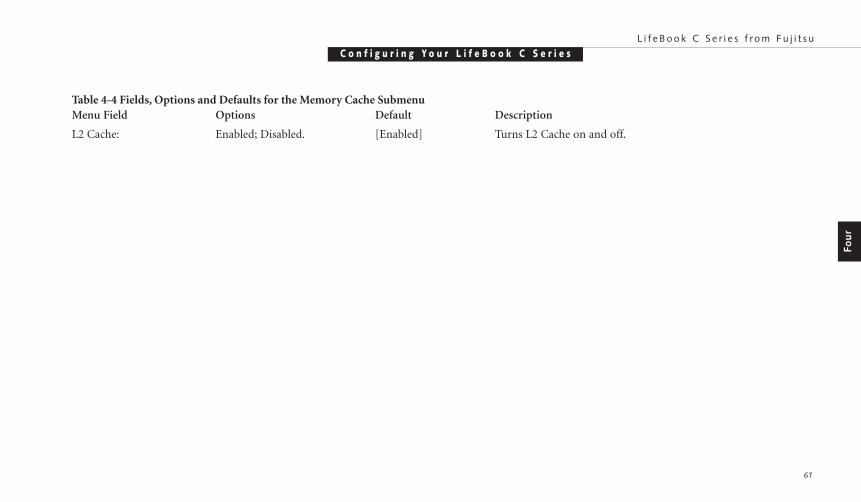
C o n f i g u r i n g Y o u r L i f e B o o k C S e r i e sL i f e B o o k C S e r i e s f r o m F u j i t s u
61
Fou
r
Menu Field Options Default Description
L2 Cache: Enabled; Disabled. [Enabled] Turns L2 Cache on and off.
Table 4-4 Fields, Options and Defaults for the Memory Cache Submenu
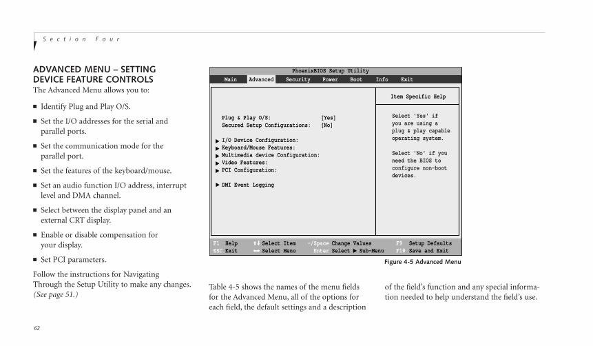
S e c t i o n F o u r
62
Table 4-5 shows the names of the menu fieldsfor the Advanced Menu, all of the options foreach field, the default settings and a description
of the field’s function and any special informa-tion needed to help understand the field’s use.
ADVANCED MENU – SETTING DEVICE FEATURE CONTROLSThe Advanced Menu allows you to:
■ Identify Plug and Play O/S.
■ Set the I/O addresses for the serial and parallel ports.
■ Set the communication mode for the parallel port.
■ Set the features of the keyboard/mouse.
■ Set an audio function I/O address, interruptlevel and DMA channel.
■ Select between the display panel and anexternal CRT display.
■ Enable or disable compensation for your display.
■ Set PCI parameters.
Follow the instructions for Navigating Through the Setup Utility to make any changes.(See page 51.)
PhoenixBIOS Setup Utility
F1 HelpESC Exit
Select ItemSelect Menu
-/SpaceEnter
F9 Setup DefaultsF10 Save and Exit
Change ValuesSelect Sub-Menu
▲
Main Advanced Security Power Boot Info Exit
Item Specific Help
▲ ▲
▲ ▲
▲
Plug & Play O/S: [Yes]Secured Setup Configurations: [No]
I/O Device Configuration:Keyboard/Mouse Features:Multimedia device Configuration:Video Features:PCI Configuration:
DMI Event Logging
Select 'Yes' if you are using a plug & play capableoperating system.
Select 'No' if youneed the BIOS toconfigure non-bootdevices.
▲
Figure 4-5 Advanced Menu

C o n f i g u r i n g Y o u r L i f e B o o k C S e r i e sL i f e B o o k C S e r i e s f r o m F u j i t s u
63
Fou
r
Menu Field Options Default Description
Plug & Play O/S: Yes; No. [Yes] Identifies whether installed operating system is plug and play.
Secured Setup Yes; No. [No] This allows the Plug and Play operating system to change default Configuration: settings. When Yes is selected it will not allow the Plug and Play
operating system to override.
I/O Device Configuration: When selected, opens the I/O Device Configuration submenu which allows the user to modify settings for parallel and serial ports, the floppy disk controller, and the local bus IDE adapter.
Keyboard/Mouse Features: When selected, opens the Keyboard/Mouse Features submenu,with Numlock parameters.
Multimedia Device When selected, opens the Multimedia Device ConfigurationConfiguration: submenu, which allows setting the hardware address and
interrupt levels of audio functions.
Video Features: When selected, opens the Video Features submenu, which allowssetting of the display parameters, including routing of videosignals to different displays.
PCI Configuration: When selected, opens the PCI Configuration submenu, which allows setting of the PCI devices.
Table 4-5 Field Names, Options and Defaults for the Advanced Menu
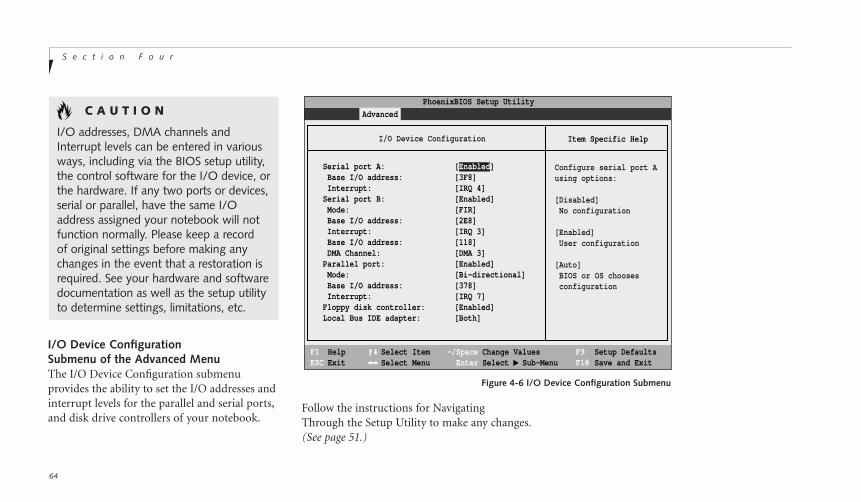
S e c t i o n F o u r
64
I/O Device ConfigurationSubmenu of the Advanced MenuThe I/O Device Configuration submenu provides the ability to set the I/O addresses andinterrupt levels for the parallel and serial ports,and disk drive controllers of your notebook.
PhoenixBIOS Setup Utility
F1 HelpESC Exit
Select ItemSelect Menu
-/SpaceEnter
F9 Setup DefaultsF10 Save and Exit
Change ValuesSelect Sub-Menu
▲
Advanced
Item Specific Help
Serial port A: [Enabled] Base I/O address: [3F8] Interrupt: [IRQ 4]Serial port B: [Enabled] Mode: [FIR] Base I/O address: [2E8] Interrupt: [IRQ 3] Base I/O address: [118] DMA Channel: [DMA 3]Parallel port: [Enabled] Mode: [Bi-directional] Base I/O address: [378] Interrupt: [IRQ 7]Floppy disk controller: [Enabled]Local Bus IDE adapter: [Both]
Configure serial port Ausing options:
[Disabled] No configuration
[Enabled] User configuration
[Auto] BIOS or OS chooses configuration
I/O Device Configuration
Figure 4-6 I/O Device Configuration Submenu
C A U T I O N
I/O addresses, DMA channels andInterrupt levels can be entered in variousways, including via the BIOS setup utility,the control software for the I/O device, orthe hardware. If any two ports or devices,serial or parallel, have the same I/Oaddress assigned your notebook will notfunction normally. Please keep a record of original settings before making anychanges in the event that a restoration isrequired. See your hardware and softwaredocumentation as well as the setup utilityto determine settings, limitations, etc.
Follow the instructions for Navigating Through the Setup Utility to make any changes.(See page 51.)

C o n f i g u r i n g Y o u r L i f e B o o k C S e r i e sL i f e B o o k C S e r i e s f r o m F u j i t s u
65
Fou
r
Table 4-6 shows the names of the menufields for the I/O Device Configuration sub-menu, all of the options for each field, thedefault settings and a description of thefield’s function and any special informationneeded to help understand the field’s use.
P O I N T
All I/O addresses in Table 4-6 arein hexadecimal.
P O I N T
To prevent IRQ and address conflicts,avoid changing the default settings. If you must change the settings, you can call 1-800-8FUJITSU for technical assistance.
C A U T I O N
The BIOS will warn you if there is aresource conflict by placing a yellow asterisk next to the device(s) reporting a conflict.
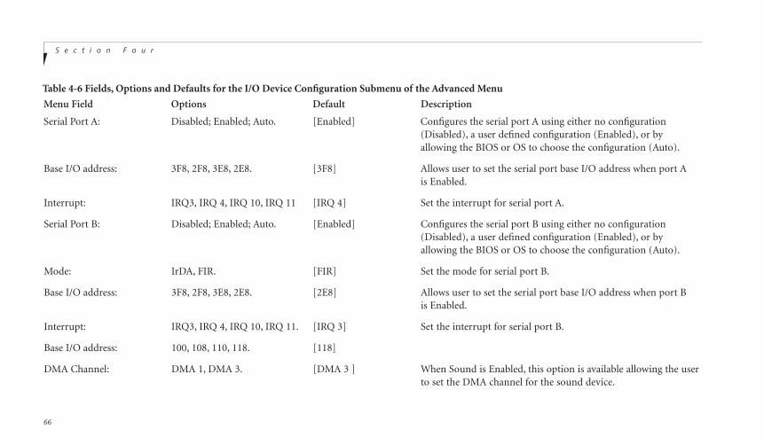
S e c t i o n F o u r
66
Table 4-6 Fields, Options and Defaults for the I/O Device Configuration Submenu of the Advanced Menu
Menu Field Options Default Description
Serial Port A: Disabled; Enabled; Auto. [Enabled] Configures the serial port A using either no configuration (Disabled), a user defined configuration (Enabled), or by allowing the BIOS or OS to choose the configuration (Auto).
Base I/O address: 3F8, 2F8, 3E8, 2E8. [3F8] Allows user to set the serial port base I/O address when port A is Enabled.
Interrupt: IRQ3, IRQ 4, IRQ 10, IRQ 11 [IRQ 4] Set the interrupt for serial port A.
Serial Port B: Disabled; Enabled; Auto. [Enabled] Configures the serial port B using either no configuration (Disabled), a user defined configuration (Enabled), or by allowing the BIOS or OS to choose the configuration (Auto).
Mode: IrDA, FIR. [FIR] Set the mode for serial port B.
Base I/O address: 3F8, 2F8, 3E8, 2E8. [2E8] Allows user to set the serial port base I/O address when port B is Enabled.
Interrupt: IRQ3, IRQ 4, IRQ 10, IRQ 11. [IRQ 3] Set the interrupt for serial port B.
Base I/O address: 100, 108, 110, 118. [118]
DMA Channel: DMA 1, DMA 3. [DMA 3 ] When Sound is Enabled, this option is available allowing the userto set the DMA channel for the sound device.

C o n f i g u r i n g Y o u r L i f e B o o k C S e r i e sL i f e B o o k C S e r i e s f r o m F u j i t s u
67
Fou
r
Table 4-6 Fields, Options and Defaults for the I/O Device Configuration Submenu of the Advanced MenuMenu Field Options Default Description
Parallel port: Disabled; Enabled; Auto. [Enabled] Configures the parallel port using either no configuration (Disabled), a user defined configuration (Enabled), or by allowing the BIOS or OS to choose the configuration (Auto).
Mode: Output Only; [Bi-directiona1] When the parallel port is enabled this option is available allowing Bi-directional; ECP. the user to set the mode for the parallel port. Bi-directional
allows two-way transfer of information between your notebook and a connected parallel device. Output Only (Half Duplex) allows information to be transferred in only one direction, from your notebook to the printer or similar device. ECP Mode allowscommunication with the ECP class of parallel I/O devices.
Base I/O address: 378; 278; 3BC. [378] Allows user to set the parallel port base I/O address when the parallel port is Enabled.
Interrupt: IRQ 5; IRQ 7. [IRQ 7] Allows user to set the parallel port interrupt when the parallelport is Enabled.
Floppy disk controller: Disabled; Enabled. [Enabled] Enables and disables the floppy disk drive controller for fixedfloppy disk drive port.
Local BusIDE adapter: Both; Disabled; [Both] Enables and disables the integrated IDE controller.Primary; Secondary.
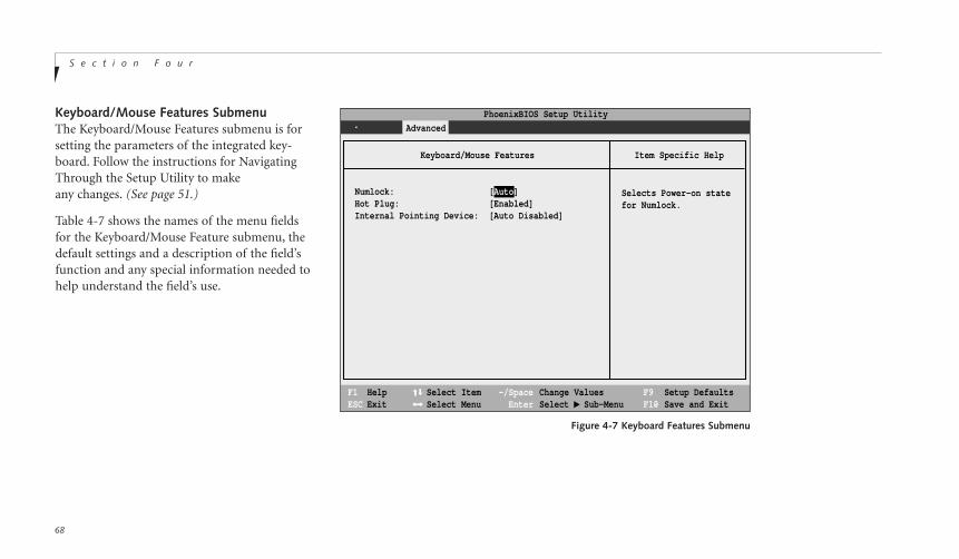
S e c t i o n F o u r
68
Keyboard/Mouse Features SubmenuThe Keyboard/Mouse Features submenu is forsetting the parameters of the integrated key-board. Follow the instructions for Navigating Through the Setup Utility to make any changes. (See page 51.)
Table 4-7 shows the names of the menu fieldsfor the Keyboard/Mouse Feature submenu, thedefault settings and a description of the field’sfunction and any special information needed tohelp understand the field’s use.
F1 HelpESC Exit
Select ItemSelect Menu
-/SpaceEnter
F9 Setup DefaultsF10 Save and Exit
Change ValuesSelect Sub-Menu
▲
Advanced Security Power Savings Exit
Item Specific Help
PhoenixBIOS Setup Utility
Selects Power-on statefor Numlock.
Keyboard/Mouse Features
Numlock:Hot Plug:Internal Pointing Device:
[Auto][Enabled][Auto Disabled]
Figure 4-7 Keyboard Features Submenu

C o n f i g u r i n g Y o u r L i f e B o o k C S e r i e sL i f e B o o k C S e r i e s f r o m F u j i t s u
69
Fou
r
Table 4-7 Fields, Options and Defaults of the Keyboard Submenu of the Advanced Menu
Menu Field Options Default Description
Numlock: Auto; On; Off. [Auto] Sets the NumLock function state when the computercompletes booting.
Hot Plug: Disabled, Enabled. [Enabled] Enables or disables the Keyboard/Mouse Hot Plug functions.
Internal Pointing [Always Enabled, [Auto Disabled] If Always Enabled is selected, the internal pointing device is Device: Auto Disabled]. always enabled. If Auto Disabled is selected, the internal pointing
device is disabled when an external pointing device is connectedwith the PS/2 port. However, if no external pointing device isconnected, the internal pointing device is enabled.
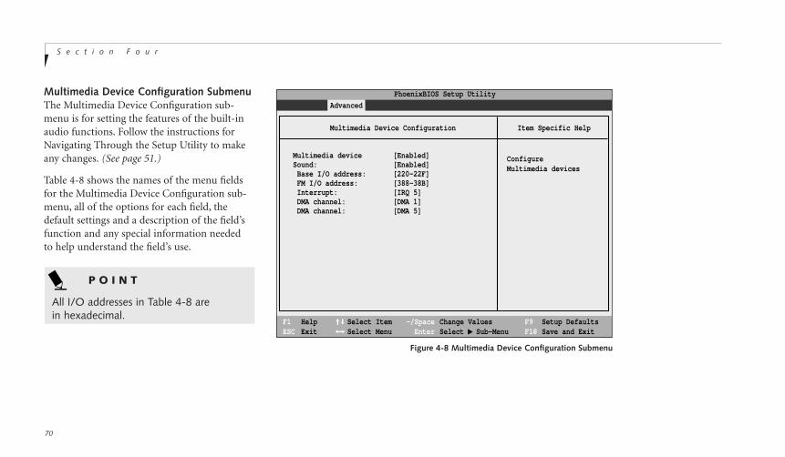
S e c t i o n F o u r
70
Multimedia Device Configuration SubmenuThe Multimedia Device Configuration sub-menu is for setting the features of the built-inaudio functions. Follow the instructions forNavigating Through the Setup Utility to makeany changes. (See page 51.)
Table 4-8 shows the names of the menu fieldsfor the Multimedia Device Configuration sub-menu, all of the options for each field, thedefault settings and a description of the field’sfunction and any special information needed to help understand the field’s use.
F1 HelpESC Exit
Select ItemSelect Menu
-/SpaceEnter
F9 Setup DefaultsF10 Save and Exit
Change ValuesSelect Sub-Menu
▲
Main Advanced Security Power Savings Exit
Item Specific Help
PhoenixBIOS Setup Utility
Configure Multimedia devices
Multimedia Device Configuration
Multimedia device [Enabled]Sound: [Enabled] Base I/O address: [220-22F] FM I/O address: [388-38B] Interrupt: [IRQ 5] DMA channel: [DMA 1] DMA channel: [DMA 5]
Figure 4-8 Multimedia Device Configuration Submenu
P O I N T
All I/O addresses in Table 4-8 arein hexadecimal.
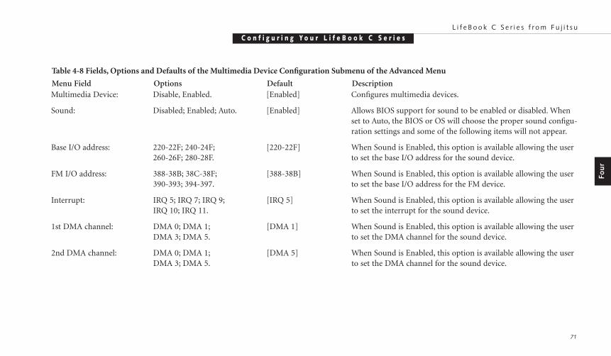
C o n f i g u r i n g Y o u r L i f e B o o k C S e r i e sL i f e B o o k C S e r i e s f r o m F u j i t s u
71
Fou
r
Table 4-8 Fields, Options and Defaults of the Multimedia Device Configuration Submenu of the Advanced Menu
Menu Field Options Default DescriptionMultimedia Device: Disable, Enabled. [Enabled] Configures multimedia devices.
Sound: Disabled; Enabled; Auto. [Enabled] Allows BIOS support for sound to be enabled or disabled. When set to Auto, the BIOS or OS will choose the proper sound configu-ration settings and some of the following items will not appear.
Base I/O address: 220-22F; 240-24F; [220-22F] When Sound is Enabled, this option is available allowing the user260-26F; 280-28F. to set the base I/O address for the sound device.
FM I/O address: 388-38B; 38C-38F; [388-38B] When Sound is Enabled, this option is available allowing the user390-393; 394-397. to set the base I/O address for the FM device.
Interrupt: IRQ 5; IRQ 7; IRQ 9; [IRQ 5] When Sound is Enabled, this option is available allowing the userIRQ 10; IRQ 11. to set the interrupt for the sound device.
1st DMA channel: DMA 0; DMA 1; [DMA 1] When Sound is Enabled, this option is available allowing the userDMA 3; DMA 5. to set the DMA channel for the sound device.
2nd DMA channel: DMA 0; DMA 1; [DMA 5] When Sound is Enabled, this option is available allowing the userDMA 3; DMA 5. to set the DMA channel for the sound device.
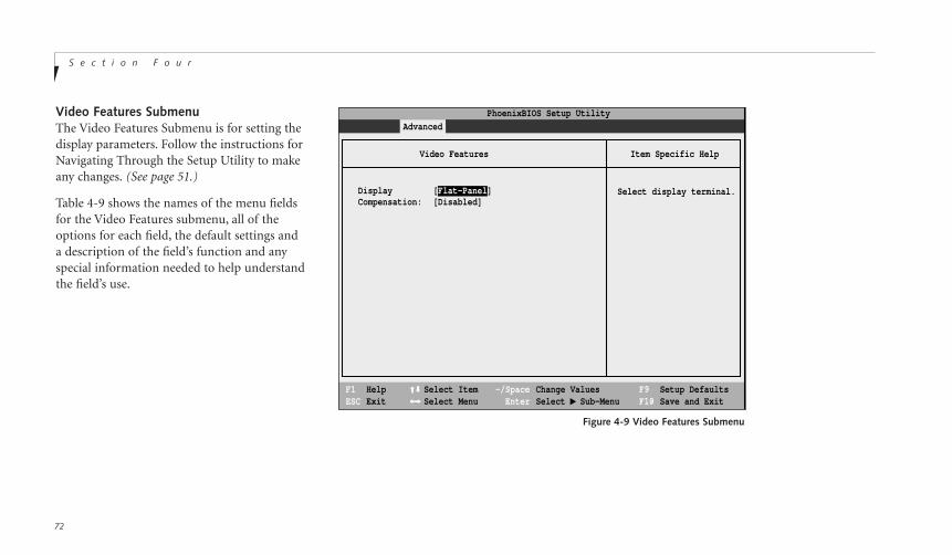
S e c t i o n F o u r
72
Video Features SubmenuThe Video Features Submenu is for setting thedisplay parameters. Follow the instructions forNavigating Through the Setup Utility to makeany changes. (See page 51.)
Table 4-9 shows the names of the menu fieldsfor the Video Features submenu, all of theoptions for each field, the default settings and a description of the field’s function and anyspecial information needed to help understandthe field’s use.
F1 HelpESC Exit
Select ItemSelect Menu
-/SpaceEnter
F9 Setup DefaultsF10 Save and Exit
Change ValuesSelect Sub-Menu
▲
Main Advanced Security Power Savings Exit
Item Specific Help
Select display terminal.
Video Features
Display [Flat-Panel]Compensation: [Disabled]
PhoenixBIOS Setup Utility
Figure 4-9 Video Features Submenu

C o n f i g u r i n g Y o u r L i f e B o o k C S e r i e sL i f e B o o k C S e r i e s f r o m F u j i t s u
73
Fou
r
Table 4-9 Fields, Options and Defaults for the Video Features Submenu of the Advanced Menu
Menu Field Options Default Description
Display: Flat-Panel; CRT; [Flat-Panel] Selects where the video signal will be routed.Simultaneous.
Compensation: Enabled; Disabled. [Disabled] Enables or disables compensation which controls spacing on the display.
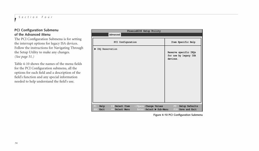
S e c t i o n F o u r
74
PCI Configuration Submenu of the Advanced MenuThe PCI Configuration Submenu is for settingthe interrupt options for legacy ISA devices.Follow the instructions for Navigating Throughthe Setup Utility to make any changes.(See page 51.)
Table 4-10 shows the names of the menu fieldsfor the PCI Configuration submenu, all theoptions for each field and a description of thefield’s function and any special informationneeded to help understand the field’s use.
F1 HelpESC Exit
Select ItemSelect Menu
-/SpaceEnter
F9 Setup DefaultsF10 Save and Exit
Change ValuesSelect Sub-Menu
▲
Main Advanced Security Power Savings Exit
Item Specific Help
Reserve specific IRQsfor use by legacy ISAdevices.
PCI Configuration
IRQ Reservation
PhoenixBIOS Setup Utility
▲
Figure 4-10 PCI Configuration Submenu

C o n f i g u r i n g Y o u r L i f e B o o k C S e r i e sL i f e B o o k C S e r i e s f r o m F u j i t s u
75
Fou
r
Menu Field Options Default Description
IRQ Reservation: Selects the IRQ — This menu allows you to set aside interrupt levels forReservation Submenu. legacy ISA devices.
Table 4-10 Fields, Options and Defaults for the PCI Configuration Submenu
Exiting from the Advanced MenuWhen you have finished setting the parameterson the Advanced Menu, you can either exitfrom setup utility or move to another menu.If you wish to exit from setup utility, press theEsc key to go to the Exit menu. If you wish tomove to another menu, use the cursor keys.
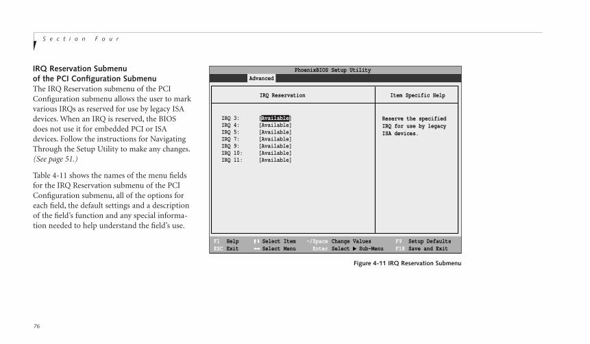
S e c t i o n F o u r
76
IRQ Reservation Submenuof the PCI Configuration SubmenuThe IRQ Reservation submenu of the PCIConfiguration submenu allows the user to markvarious IRQs as reserved for use by legacy ISAdevices. When an IRQ is reserved, the BIOSdoes not use it for embedded PCI or ISAdevices. Follow the instructions for NavigatingThrough the Setup Utility to make any changes.(See page 51.)
Table 4-11 shows the names of the menu fieldsfor the IRQ Reservation submenu of the PCIConfiguration submenu, all of the options foreach field, the default settings and a descriptionof the field’s function and any special informa-tion needed to help understand the field’s use.
Figure 4-11 IRQ Reservation Submenu
F1 HelpESC Exit
Select ItemSelect Menu
-/SpaceEnter
F9 Setup DefaultsF10 Save and Exit
Change ValuesSelect Sub-Menu
▲
Main Advanced Security Power Savings Exit
Item Specific Help
Reserve the specifiedIRQ for use by legacyISA devices.
IRQ Reservation
PhoenixBIOS Setup Utility
IRQ 3: [Available]IRQ 4: [Available]IRQ 5: [Available]IRQ 7: [Available]IRQ 9: [Available]IRQ 10: [Available]IRQ 11: [Available]

C o n f i g u r i n g Y o u r L i f e B o o k C S e r i e sL i f e B o o k C S e r i e s f r o m F u j i t s u
77
Table 4-11 Fields, Options and Defaults for the IRQ Reservation Submenu of the of the PCI Configuration Submenu of the Advanced Menu
Menu Field Options Default Description
IRQ 3: Available; Reserved. [Available] Reserves IRQ 3. If Reserved is selected, the BIOS reserves IRQ 3 for use by legacy ISA devices and does not use it for embedded PCI or ISA devices. IRQ 3 is removed from the IRQ bitmap in the PCI IRQ routing table.
IRQ 4: Available; Reserved. [Available] Reserves IRQ 4.
IRQ 5: Available; Reserved. [Available] Reserves IRQ 5.
IRQ 7: Available; Reserved. [Available] Reserves IRQ 7.
IRQ 9: Available; Reserved. [Available] Reserves IRQ 9.
IRQ 10: Available; Reserved. [Available] Reserves IRQ 10.
IRQ 11: Available; Reserved. [Available] Reserves IRQ 11.
Fou
r
C A U T I O N
Only IRQ's 9, 10, & 11 can be reservedwithout conflict.

S e c t i o n F o u r
78
DMI Event Logging Submenu of the Advanced MenuThe DMI Event Logging Submenu is for settingup the logs DMI event logging. Follow theinstructions for Navigating Through the SetupUtility to make any changes. (See page 51.)
Table 4-12 shows the names of the menu fieldsfor the DMI Event Logging submenu, all theoptions for each field, the default settings and a description of the field’s function and anyspecial information needed to help understandthe field’s use.
F1 HelpESC Exit
Select ItemSelect Menu
-/SpaceEnter
F9 Setup DefaultsF10 Save and Exit
Change ValuesSelect Sub-Menu
▲
Main Advanced Security Power Savings Exit
Item Specific Help
'Yes' clears all DMIevent logs at next boot.The value is reset to'No' after clearinglogs.
DMI Event Logging
PhoenixBIOS Setup Utility
Event log capacity: Space AvailableEvent log validity: Valid
Clear all DMI event logs: [No]
Event Logging: [Enabled] System Boot Event: [Disabled]
Figure 4-12 DMI Event Logging Submenu

C o n f i g u r i n g Y o u r L i f e B o o k C S e r i e sL i f e B o o k C S e r i e s f r o m F u j i t s u
79
Menu Field Options Default Description
Event log capacity: Display only. [Space Available]
Event log validity: Display only. [Valid]
Clear all DMI event logs: Yes; No. [No] A Yes selection causes the event logs to clear at the next boot.Once the logs are cleared this automatically sets to No until resetto yes by selecting yes here.
Event Logging: Enabled; Disabled. [Enabled] Turns event logging on and off for all DMI events.
System Boot Event: Enabled; Disabled. [Disabled] Turns event logging on and off for DMI system boot events.
Fou
r
Table 4-12 Fields, options and Defaults for the DMI Event Logging Submenu
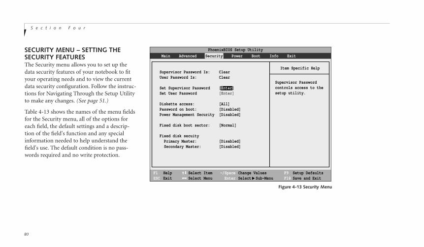
S e c t i o n F o u r
80
SECURITY MENU – SETTING THESECURITY FEATURESThe Security menu allows you to set up thedata security features of your notebook to fityour operating needs and to view the currentdata security configuration. Follow the instruc-tions for Navigating Through the Setup Utilityto make any changes. (See page 51.)
Table 4-13 shows the names of the menu fieldsfor the Security menu, all of the options foreach field, the default settings and a descrip-tion of the field's function and any specialinformation needed to help understand thefield's use. The default condition is no pass-words required and no write protection.
F1 HelpESC Exit
Select ItemSelect Menu
-/SpaceEnter
F9 Setup DefaultsF10 Save and Exit
Change ValuesSelect Sub-Menu
▲
Main Advanced Security Power Boot Info Exit
Item Specific Help
Supervisor Passwordcontrols access to the setup utility.
PhoenixBIOS Setup Utility
Supervisor Password Is: ClearUser Password Is: Clear
Set Supervisor Password [Enter]Set User Password [Enter] Diskette access: [All]Password on boot: [Disabled]Power Management Security [Disabled]
Fixed disk boot sector: [Normal]
Fixed disk secuity Primary Master: [Disabled] Secondary Master: [Disabled]
Figure 4-13 Security Menu
C o n f i g u r i n g Y o u r L i f e B o o k C S e r i e sL i f e B o o k C S e r i e s f r o m F u j i t s u
81
Fou
r
P O I N T
If you set a password, write it down andkeep it in a safe place. If you forget thepassword you will have to contact yoursupport representative to regain accessto your secured functions and data.
C A U T I O N
Entering a password incorrectly 3 times in a row will cause the keyboard andmouse to be locked out and the warning[System Disabled] to be displayed. Ifthis happens restart the computer byturning off and on the power with thepower button and use the correctpassword on reboot.
P O I N T
If you make an error when re-enteringthe password a [Warning] will be displayed on the screen. To try againpress the Enter key and then retype thepassword. Press the Esc key to abort the password setting process.
C A U T I O N
If the Power Management Security isEnabled and the Password on Boot isDisabled you will not be able to resumeoperation from the Suspend or Save-to-Disk modes.
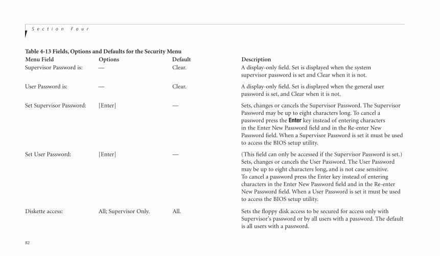
S e c t i o n F o u r
82
Menu Field Options Default DescriptionSupervisor Password is: — Clear. A display-only field. Set is displayed when the system
supervisor password is set and Clear when it is not.
User Password is: — Clear. A display-only field. Set is displayed when the general userpassword is set, and Clear when it is not.
Set Supervisor Password: [Enter] — Sets, changes or cancels the Supervisor Password. The SupervisorPassword may be up to eight characters long. To cancel a password press the Enter key instead of entering characters in the Enter New Password field and in the Re-enter New Password field. When a Supervisor Password is set it must be usedto access the BIOS setup utility.
Set User Password: [Enter] — (This field can only be accessed if the Supervisor Password is set.)Sets, changes or cancels the User Password. The User Passwordmay be up to eight characters long, and is not case sensitive.To cancel a password press the Enter key instead of enteringcharacters in the Enter New Password field and in the Re-enter New Password field. When a User Password is set it must be used to access the BIOS setup utility.
Diskette access: All; Supervisor Only. All. Sets the floppy disk access to be secured for access only withSupervisor's password or by all users with a password. The defaultis all users with a password.
Table 4-13 Fields, Options and Defaults for the Security Menu

C o n f i g u r i n g Y o u r L i f e B o o k C S e r i e sL i f e B o o k C S e r i e s f r o m F u j i t s u
83
Fou
r
Menu Field Options Default Description
Password on boot: Enabled; Disabled. Disabled. When set to Enabled, a password (User or Supervisor) is requiredafter the Power On Self Test (POST) before the operating systemwill be read from a disk. When set to Disabled no password isrequired. If no Supervisor Password is set this feature is notavailable and no password is required.
Power Management Enabled; Disabled. Disabled. When set to Enabled, a password, is required upon Resume from Security: Suspend or Save-to-Disk Mode.
Fixed disk boot sector: Normal; Write Protect. [Normal] Write protects boot sector on hard disk to protect against viruses.
Fixed disk security:
Primary Master: Enabled; Disabled. [Disabled] When set to Enabled, a password (User or Supervisor) is requiredto access data on the disk drive on the Primary Master interface.
Secondary Master: Enabled; Disabled. [Disabled] When set to Enabled, a password (User or Supervisor) is requiredto access data on the Secondary Master interface.
Table 4-13 Fields, Options and Defaults for the Security Menu
S e c t i o n F o u r
84
P O I N T
Boot sector protection must be set to[Normal] to install or upgrade an operating system.
Exiting from the Security MenuWhen you have finished setting the parameterson the Security Menu, you can either exit fromsetup utility or move to another menu. If youwish to exit from setup utility, press the Esc keyto go to the Exit Menu. If you wish to move toanother menu, use the cursor keys.
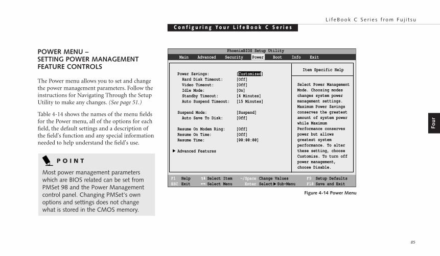
C o n f i g u r i n g Y o u r L i f e B o o k C S e r i e sL i f e B o o k C S e r i e s f r o m F u j i t s u
85
Fou
r
POWER MENU – SETTING POWER MANAGEMENTFEATURE CONTROLS
The Power menu allows you to set and changethe power management parameters. Follow theinstructions for Navigating Through the SetupUtility to make any changes. (See page 51.)
Table 4-14 shows the names of the menu fieldsfor the Power menu, all of the options for eachfield, the default settings and a description ofthe field's function and any special informationneeded to help understand the field's use.
F1 HelpESC Exit
Select ItemSelect Menu
-/SpaceEnter
F9 Setup DefaultsF10 Save and Exit
Change ValuesSelect Sub-Menu
▲
Item Specific Help
Select Power ManagementMode. Choosing modeschanges system powermanagement settings.Maximum Power Savingsconserves the greatestamount of system powerwhile MaximumPerformance conservespower but allowsgreatest systemperformance. To alterthese setting, chooseCustomize. To turn offpower management,choose Disable.
PhoenixBIOS Setup Utility
Power Savings: [Customized] Hard Disk Timeout: [Off] Video Timeout: [Off] Idle Mode: [On] Standby Timeout: [4 Minutes] Auto Suspend Timeout: [15 Minutes]
Suspend Mode: [Suspend] Auto Save To Disk: [Off]
Resume On Modem Ring: [Off]Resume On Time: [Off]Resume Time: [00:00:00]
Advanced Features
▲
Main Advanced Security Power Boot Info Exit
Figure 4-14 Power Menu
P O I N T
Most power management parameterswhich are BIOS related can be set fromPMSet 98 and the Power Managementcontrol panel. Changing PMSet's ownoptions and settings does not changewhat is stored in the CMOS memory.

S e c t i o n F o u r
86
S e c t i o n F o u r
Menu Field Options Default DescriptionPower Savings: Customized; Maximum [Customized] Sets the power savings parameters to a factory installed
Power Savings; Maximum combination of parameters, a custom set of parameters set byPerformance, Disabled. you or no power saving features.
Hard Disk Timeout: 30 seconds to [Off] Sets the length of time that the hard drive can be inactive before 20 minutes; Off. your notebook automatically turns off the power to the hard
drive controller and drive motor. If you choose a factory installedcombination of parameters this field will display the setting. Ifyou choose to customize the parameters you will be able to setthis yourself. The options available vary from Off, which has noinactivity shutoff, to 20 minutes.
Video Timeout: 2 minutes to [Off] Sets the length of time without any user input device activity 20 minutes; Off. before the display is turned off. If you choose a factory combina
tion of parameters, this field will display the setting. If you choose to customize the parameters, you will be able to set this yourself.Off has no inactivity shutoff.
Idle Mode: On; Off. [On] Turns on and off the slow down of the CPU during periods ofinactivity. When this is turned on the CPU clock slows by theamount set in the Advanced submenu when there is no activityfor 16 seconds or more. Normal speed resumes automatically assoon as there is any activity.
Table 4-14 Fields, Options and Defaults for the Power Menu
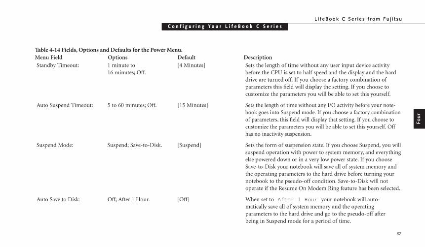
C o n f i g u r i n g Y o u r L i f e B o o k C S e r i e sL i f e B o o k C S e r i e s f r o m F u j i t s u
87
Fou
r
C o n f i g u r i n g Y o u r L i f e B o o k C S e r i e sL i f e B o o k C S e r i e s f r o m F u j i t s u
Menu Field Options Default DescriptionStandby Timeout: 1 minute to [4 Minutes] Sets the length of time without any user input device activity
16 minutes; Off. before the CPU is set to half speed and the display and the harddrive are turned off. If you choose a factory combination ofparameters this field will display the setting. If you choose tocustomize the parameters you will be able to set this yourself.
Auto Suspend Timeout: 5 to 60 minutes; Off. [15 Minutes] Sets the length of time without any I/O activity before your note-book goes into Suspend mode. If you choose a factory combinationof parameters, this field will display that setting. If you choose tocustomize the parameters you will be able to set this yourself. Offhas no inactivity suspension.
Suspend Mode: Suspend; Save-to-Disk. [Suspend] Sets the form of suspension state. If you choose Suspend, you willsuspend operation with power to system memory, and everythingelse powered down or in a very low power state. If you chooseSave-to-Disk your notebook will save all of system memory andthe operating parameters to the hard drive before turning yournotebook to the pseudo-off condition. Save-to-Disk will notoperate if the Resume On Modem Ring feature has been selected.
Auto Save to Disk: Off; After 1 Hour. [Off] When set to After 1 Hour your notebook will auto-matically save all of system memory and the operating parameters to the hard drive and go to the pseudo-off after being in Suspend mode for a period of time.
Table 4-14 Fields, Options and Defaults for the Power Menu.
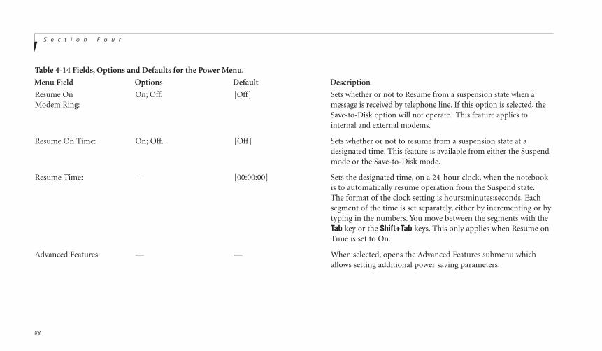
S e c t i o n F o u r
88
Menu Field Options Default Description
Resume On On; Off. [Off] Sets whether or not to Resume from a suspension state when aModem Ring: message is received by telephone line. If this option is selected, the
Save-to-Disk option will not operate. This feature applies tointernal and external modems.
Resume On Time: On; Off. [Off] Sets whether or not to resume from a suspension state at adesignated time. This feature is available from either the Suspendmode or the Save-to-Disk mode.
Resume Time: — [00:00:00] Sets the designated time, on a 24-hour clock, when the notebookis to automatically resume operation from the Suspend state.The format of the clock setting is hours:minutes:seconds. Eachsegment of the time is set separately, either by incrementing or bytyping in the numbers. You move between the segments with theTab key or the Shift+Tab keys. This only applies when Resume onTime is set to On.
Advanced Features: — — When selected, opens the Advanced Features submenu whichallows setting additional power saving parameters.
Table 4-14 Fields, Options and Defaults for the Power Menu.
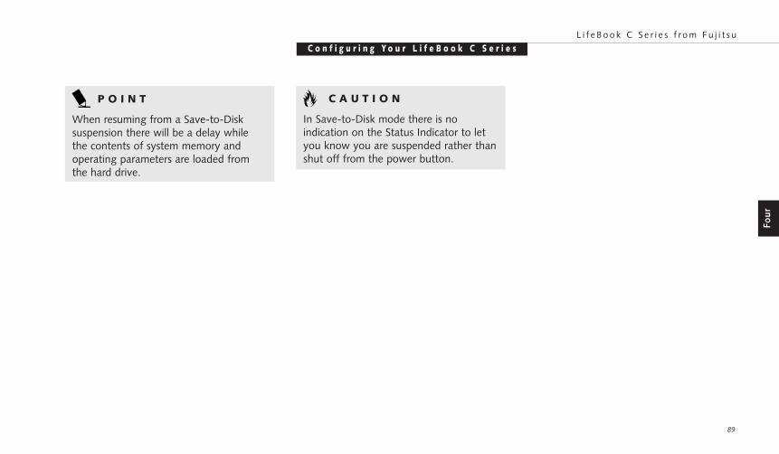
C o n f i g u r i n g Y o u r L i f e B o o k C S e r i e sL i f e B o o k C S e r i e s f r o m F u j i t s u
89
Fou
r
P O I N T
When resuming from a Save-to-Disksuspension there will be a delay whilethe contents of system memory andoperating parameters are loaded fromthe hard drive.
C A U T I O N
In Save-to-Disk mode there is no indication on the Status Indicator to letyou know you are suspended rather thanshut off from the power button.
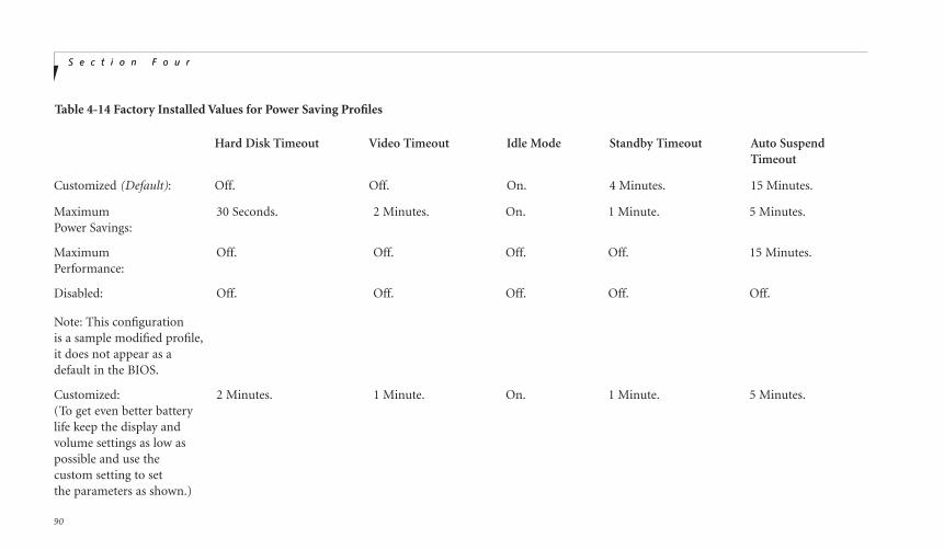
S e c t i o n F o u r
90
S e c t i o n F o u r
Hard Disk Timeout Video Timeout Idle Mode Standby Timeout Auto Suspend Timeout
Customized (Default): Off. Off. On. 4 Minutes. 15 Minutes.
Maximum 30 Seconds. 2 Minutes. On. 1 Minute. 5 Minutes.Power Savings:
Maximum Off. Off. Off. Off. 15 Minutes.Performance:
Disabled: Off. Off. Off. Off. Off.
Note: This configurationis a sample modified profile,it does not appear as adefault in the BIOS.
Customized: 2 Minutes. 1 Minute. On. 1 Minute. 5 Minutes.(To get even better batterylife keep the display andvolume settings as low aspossible and use thecustom setting to setthe parameters as shown.)
Table 4-14 Factory Installed Values for Power Saving Profiles

C o n f i g u r i n g Y o u r L i f e B o o k C S e r i e sL i f e B o o k C S e r i e s f r o m F u j i t s u
91
Fou
r
Advanced Features Submenu of the Power MenuThe Advanced Features submenu is for settingsome non-time related power saving parame-ters. Follow the instructions for NavigatingThrough the Setup Utility to make anychanges. (See page 51.)
Table 4-15 shows the names of the menu fieldsfor the Video Features submenu, all of theoptions for each field, the default settings and a description of the field's function and anyspecial information needed to help understandthe field's use.
PhoenixBIOS Setup Utility
F1 HelpESC Exit
Select ItemSelect Menu
-/SpaceEnter
F9 Setup DefaultsF10 Save and Exit
Change ValuesSelect Sub-Menu
Item Specific Help
Set the SUS/RES Switch.
▲
Power
SUS/RES Switch: [Enabled]Lid Closure Suspend: [On]Lid Open Resume: [On]APM CPU Idle Mode: [Low Power]Serial Mouse Activity: [Disabled]
Advanced Features
Figure 4-15 Advanced Features Submenu
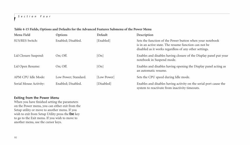
S e c t i o n F o u r
92
S e c t i o n F o u r
Menu Field Options Default Description
SUS/RES Switch: Enabled; Disabled. [Enabled] Sets the function of the Power button when your notebookis in an active state. The resume function can not bedisabled as it works regardless of any other settings.
Lid Closure Suspend: On; Off. [On] Enables and disables having closure of the Display panel put yournotebook in Suspend mode.
Lid Open Resume: On; Off. [On] Enables and disables having opening the Display panel acting asan automatic resume.
APM CPU Idle Mode: Low Power; Standard. [Low Power] Sets the CPU speed during Idle mode.
Serial Mouse Activity: Enabled; Disabled. [Disabled] Enables and disables having activity on the serial port cause thesystem to reactivate from inactivity timeouts.
Table 4-15 Fields, Options and Defaults for the Advanced Features Submenu of the Power Menu
Exiting from the Power MenuWhen you have finished setting the parameterson the Power menu, you can either exit from theSetup utility or move to another menu. If youwish to exit from Setup Utility press the Esc keyto go to the Exit menu. If you wish to move toanother menu, use the cursor keys.
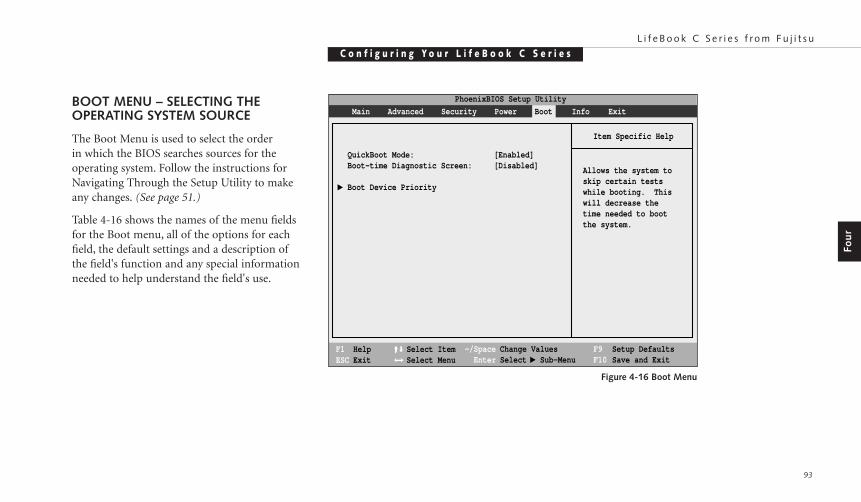
C o n f i g u r i n g Y o u r L i f e B o o k C S e r i e sL i f e B o o k C S e r i e s f r o m F u j i t s u
93
Fou
r
BOOT MENU – SELECTING THEOPERATING SYSTEM SOURCE
The Boot Menu is used to select the orderin which the BIOS searches sources for theoperating system. Follow the instructions forNavigating Through the Setup Utility to makeany changes. (See page 51.)
Table 4-16 shows the names of the menu fieldsfor the Boot menu, all of the options for eachfield, the default settings and a description ofthe field's function and any special informationneeded to help understand the field's use.
PhoenixBIOS Setup Utility
F1 HelpESC Exit
Select ItemSelect Menu
Main Advanced Security Power Boot Info Exit
Item Specific Help
Allows the system toskip certain testswhile booting. Thiswill decrease the time needed to bootthe system.
QuickBoot Mode: [Enabled]Boot-time Diagnostic Screen: [Disabled]
Boot Device Priority
▲
-/SpaceEnter
F9 Setup DefaultsF10 Save and Exit
Change ValuesSelect Sub-Menu
▲
Figure 4-16 Boot Menu
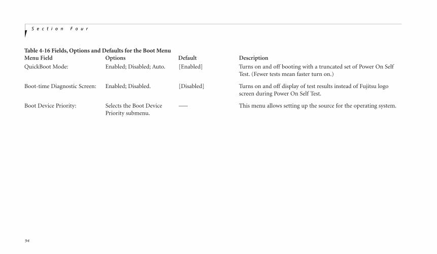
S e c t i o n F o u r
94
S e c t i o n F o u r
Menu Field Options Default Description
QuickBoot Mode: Enabled; Disabled; Auto. [Enabled] Turns on and off booting with a truncated set of Power On SelfTest. (Fewer tests mean faster turn on.)
Boot-time Diagnostic Screen: Enabled; Disabled. [Disabled] Turns on and off display of test results instead of Fujitsu logoscreen during Power On Self Test.
Boot Device Priority: Selects the Boot Device –— This menu allows setting up the source for the operating system.Priority submenu.
Table 4-16 Fields, Options and Defaults for the Boot Menu
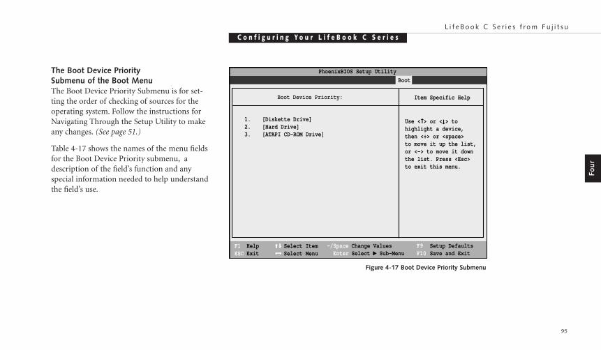
C o n f i g u r i n g Y o u r L i f e B o o k C S e r i e sL i f e B o o k C S e r i e s f r o m F u j i t s u
95
Fou
r
The Boot Device Priority Submenu of the Boot MenuThe Boot Device Priority Submenu is for set-ting the order of checking of sources for theoperating system. Follow the instructions forNavigating Through the Setup Utility to makeany changes. (See page 51.)
Table 4-17 shows the names of the menu fieldsfor the Boot Device Priority submenu, adescription of the field’s function and anyspecial information needed to help understandthe field’s use.
PhoenixBIOS Setup Utility
F1 HelpESC Exit
Select ItemSelect Menu
Main Advanced Security Power Savings Boot
Item Specific Help
Use < > or < > tohighlight a device,then <+> or <space> to move it up the list,or <-> to move it downthe list. Press <Esc>to exit this menu.
1. [Diskette Drive]2. [Hard Drive]3. [ATAPI CD-ROM Drive]
➞
➞
-/SpaceEnter
F9 Setup DefaultsF10 Save and Exit
Change ValuesSelect Sub-Menu
▲
Boot Device Priority:
Figure 4-17 Boot Device Priority Submenu
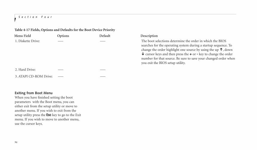
S e c t i o n F o u r
96
S e c t i o n F o u r
Menu Field Options Default Description
1. Diskette Drive: –— –— The boot selections determine the order in which the BIOSsearches for the operating system during a startup sequence. Tochange the order highlight one source by using the up Õ, down Ô cursor keys and then press the + or - key to change the ordernumber for that source. Be sure to save your changed order whenyou exit the BIOS setup utility.
2. Hard Drive: –— –—
3. ATAPI CD-ROM Drive: –— –—
Table 4-17 Fields, Options and Defaults for the Boot Device Priority
Exiting from Boot MenuWhen you have finished setting the bootparameters with the Boot menu, you caneither exit from the setup utility or move toanother menu. If you wish to exit from thesetup utility press the Esc key to go to the Exitmenu. If you wish to move to another menu,use the cursor keys.

C o n f i g u r i n g Y o u r L i f e B o o k C S e r i e sL i f e B o o k C S e r i e s f r o m F u j i t s u
97
Fou
r
INFO MENU – DISPLAYING BASICSYSTEM INFORMATIONThe Info menu is a display only menu that provides the configuration information for your notebook. Follow the instructions forNavigating Through the Setup Utility to makeany changes. (See page 51.)
Table 4-18 shows the names of the menu fieldsfor the Info menu, the default settings and adescription of the field’s function and anyspecial information needed to help understandthe field’s use.
PhoenixBIOS Setup Utility
F1 HelpESC Exit
Select ItemSelect Menu
-/Space Change Values Enter Select Sub-Menu
F9 Setup Defaults F10 Save and Exit
Main Advanced Security Power Savings Boot Info
Item Specific HelpBIOS Version: 1.20BIOS Date: 03/10/1999BIOS Area: E800h - FFFFh
CPU Type: Pentium II(R) OR Intel(R) Celeron(TM) processor
CPU Speed: 333 MHzL1 Cache: 32 KBL2 Cache: 256 KB OR 128 KB
Total Memory: 64 MB OR 32 MB On Board: 64 MB SDRAM OR 32 MB SDRAM DIMM: Not Installed
Asset Number: None
▲
Figure 4-18 Info Menu

S e c t i o n F o u r
98
S e c t i o n F o u r
Menu Field Options Default
BIOS Version: –— 1.20.
BIOS Date: –— 03/10/1999.
BIOS Area: –— E800h – FFFFh.
CPU Type: –— Pentium II (R)(C360) or Intel(R) Celeron(TM)(C352).
CPU Speed: –— 333 MHz.
L1 Cache: –— 32 KB.
L2 Cache: –— 256 KB(C360) or 128 KB(C352).
Total Memory: –— 64 MB(C360) or 32 MB(C352).
On Board: –— 64 MB(C360) or 32 MB SDRAM(C352).
DIMM: –— Not Installed.
Asset Number: –— None.
Table 4-18 Fields, Options and Defaults for the Info Menu

C o n f i g u r i n g Y o u r L i f e B o o k C S e r i e sL i f e B o o k C S e r i e s f r o m F u j i t s u
99
Fou
r
EXIT MENU – LEAVING THE SETUP UTILITYThe Exit Menu is used to leave the setuputility. Follow the instructions for NavigatingThrough the Setup Utility to make anychanges. (See page 51.)
Table 4-19 shows the names of the menu fieldsfor the Exit menu, a description of the field'sfunction and any special information neededto help understand the field's use.
PhoenixBIOS Setup Utility
F1 HelpESC Exit
Select ItemSelect Menu
-/Space Change Values Enter Select Sub-Menu
F9 Setup Defaults F10 Save and Exit
Main Advanced Security Power Savings Boot Exit
Item Specific Help
Exit System Setup andsave your changes toCMOS.
Exit Saving ChangesExit Discarding ChangesLoad Setup DefaultsDiscard Changes Save Changes
▲
Figure 4-19 Exit Menu
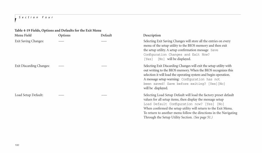
S e c t i o n F o u r
100
Table 4-19 Fields, Options and Defaults for the Exit Menu
S e c t i o n F o u r
Menu Field Options Default Description
Exit Saving Changes: –— –— Selecting Exit Saving Changes will store all the entries on everymenu of the setup utility to the BIOS memory and then exit the setup utility. A setup confirmation message Save Configuration Changes and Exit Now? [Yes] [No] will be displayed.
Exit Discarding Changes: –— –— Selecting Exit Discarding Changes will exit the setup utility without writing to the BIOS memory. When the BIOS recognizes thisselection it will load the operating system and begin operation.A message setup warning: Configuration has not been saved! Save before exiting? [Yes][No]will be displayed.
Load Setup Default: –— –— Selecting Load Setup Default will load the factory preset defaultvalues for all setup items, then display the message setupLoad Default Configuration now? [Yes] [No]When confirmed the setup utility will return to the Exit Menu.To return to another menu follow the directions in the NavigatingThrough the Setup Utility Section. (See page 51.)

C o n f i g u r i n g Y o u r L i f e B o o k C S e r i e sL i f e B o o k C S e r i e s f r o m F u j i t s u
101
Fou
r
Discard Changes: –— –— Load previous values from CMOS for all setup items. Display the following message: Load previous confi guration now? [Yes] [No]
Save Changes: –— –— Selecting Save Changes will cause the new settings in all menus to be written to the BIOS memory. Save Confi guration Changes now? [Yes] [No] When confirmed the setup
utility will return to the Exit menu. To return to another menu,follow the directions in the Navigating Through the Setup Utility section. (See page 51.)
Table 4-19 Fields, Options and Defaults for the Exit Menu
Menu Field Options Default Description

S e c t i o n F o u r
102
SETTING UP YOUR SAVE-TO-DISK FILE ALLOCATIONYour notebook comes with an allocation of spaceon the internal hard drive adequate to operate theSave-to-Disk function for the amount of memoryinstalled at the factory. If you add a memoryupgrade module or do not use the Save-to-Diskfunction and wish to free up the disk space, youwill need to change your allocation. The utility tochange the allocations is PHDISK.EXE and isactivated from the MS-DOS prompt.
PHDISK allows you to perform five differentfunctions related to the Save-to-Disk space onyour internal hard drive. They are:
1. Allocate a space for the Save-to-Disk function.
2. Remove all space allocation for theSave-to-Disk function.
3. Find out details about the hard drive and thecurrent Save-to-Disk space allocation.
4. Re-allocate space and mark bad blocks in thespace allocated to the Save-to-Disk functionwhen a disk error has occurred.
5. Find out how much space is needed toperform the Save-to-Disk function withDiscard Charges: Load previous values fromCMOS for all setup items.
To find out how much space is needed to per-form the Save-to-Disk function with the cur-rent memory configuration and how muchunused space is available on the internal harddrive, do the following:
1. Restart your notebook in MS-DOS mode.
2. At the DOS prompt typeCD C:\Fujitsu
3. Type PHDISK
4. Press the Enter key.
The screen will display the amount disk spaceneeded to perform the Save-to-Disk functionwith the current memory configuration andhow much unused space is available on theinternal hard drive.
To find out details about the hard drive andthe current Save-to-Disk space allocation, dothe following:
1. Restart your notebook in MS-DOS mode.
2. At the DOS prompt typeCD C:\Fujitsu
3. Type PHDISK /INFO
4. Press the Enter key.
5. The screen will display the size of the spacecurrently allocated to the Save-to-Disk func-tion and other parameters about the spaceand the hard drive.
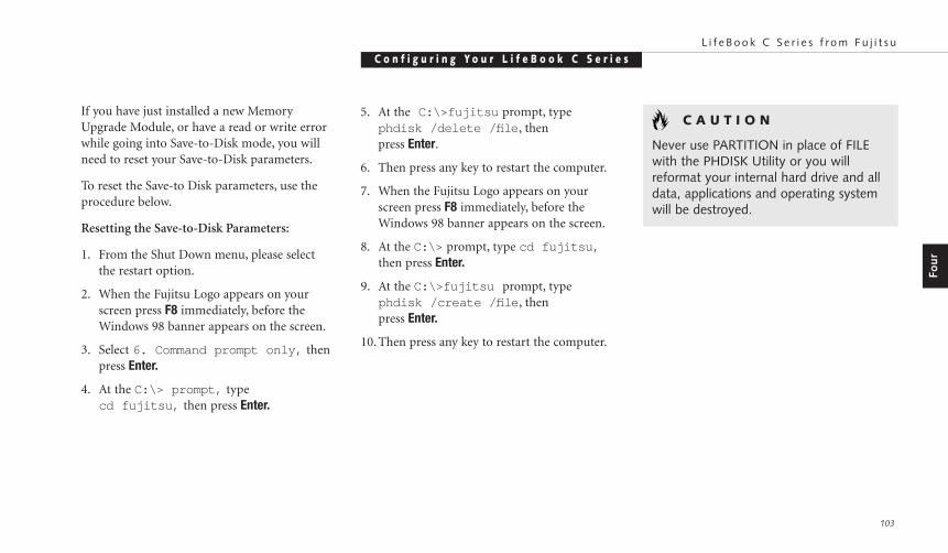
C o n f i g u r i n g Y o u r L i f e B o o k C S e r i e sL i f e B o o k C S e r i e s f r o m F u j i t s u
103
Fou
r
C A U T I O N
Never use PARTITION in place of FILEwith the PHDISK Utility or you will reformat your internal hard drive and alldata, applications and operating systemwill be destroyed.
If you have just installed a new MemoryUpgrade Module, or have a read or write errorwhile going into Save-to-Disk mode, you willneed to reset your Save-to-Disk parameters.
To reset the Save-to Disk parameters, use theprocedure below.
Resetting the Save-to-Disk Parameters:
1. From the Shut Down menu, please selectthe restart option.
2. When the Fujitsu Logo appears on yourscreen press F8 immediately, before theWindows 98 banner appears on the screen.
3. Select 6. Command prompt only, thenpress Enter.
4. At the C:\> prompt, typecd fujitsu, then press Enter.
5. At the C:\>fujitsu prompt, typephdisk /delete /fi le , thenpress Enter.
6. Then press any key to restart the computer.
7. When the Fujitsu Logo appears on yourscreen press F8 immediately, before theWindows 98 banner appears on the screen.
8. At the C:\> prompt, type cd fujitsu,then press Enter.
9. At the C:\>fujitsu prompt, typephdisk /create /fi le , thenpress Enter.
10. Then press any key to restart the computer.

U s e r I n s t a l l a b l e F e a t u r e sS e c t i o n F i v e
Lithium ion Battery . . . . . . . . . . . . . 106
PC Cards . . . . . . . . . . . . . . . . . . 108
Parallel Port Devices . . . . . . . . . . . . . 110
Serial Port Devices. . . . . . . . . . . . . . 110
USB Devices . . . . . . . . . . . . . . . . . 110
Microphone . . . . . . . . . . . . . . . . . 110
Stereo Line In Devices . . . . . . . . . . . . 110
Headphones. . . . . . . . . . . . . . . . . 110
Telephone Lines . . . . . . . . . . . . . . . 111
Mouse, Keyboard, or Keypad . . . . . . . . 111
External Monitor . . . . . . . . . . . . . . 111
Theft Prevention Lock . . . . . . . . . . . . 112
Memory Upgrade Module . . . . . . . . . 112
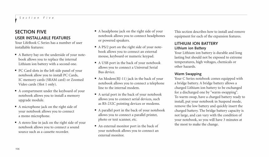
S e c t i o n F i v e
106
SECTION FIVEUSER INSTALLABLE FEATURESYour LifeBook C Series has a number of userinstallable features:
■ A Battery bay on the underside of your note-book allows you to replace the internalLithium ion battery with a second one.
■ PC Card slots in the left side panel of yournotebook allow you to install PC Cards,IC memory cards (SRAM card) or ZoomedVideo cards (Slot 1 only).
■ A compartment under the keyboard of your notebook allows you to install a memoryupgrade module.
■ A microphone jack on the right side ofyour notebook allows you to connect a mono microphone.
■ A stereo line in jack on the right side of yournotebook allows you to connect a soundsource such as a cassette recorder.
■ A headphone jack on the right side of yournotebook allows you to connect headphonesor powered speakers.
■ A PS/2 port on the right side of your note-book allows you to connect an externalmouse, keyboard or numeric keypad.
■ A USB port in the back of your notebookallows you to connect a Universal Serial Bus device.
■ An Modem(RJ-11) jack in the back of yournotebook allows you to connect a telephoneline to the internal modem.
■ A serial port in the back of your notebookallows you to connect serial devices, such as RS-232C pointing devices or modems.
■ A parallel port in the back of your notebookallows you to connect a parallel printer,photo or text scanner, etc.
■ An external monitor port in the back ofyour notebook allows you to connect anexternal monitor.
This section describes how to install and removeequipment for each of the expansion features.
LITHIUM ION BATTERYLithium ion BatteryYour Lithium ion battery is durable and longlasting but should not be exposed to extremetemperatures, high voltages, chemicals or other hazards.
Warm SwappingYour C Series notebook comes equipped witha bridge battery. A bridge battery allows acharged Lithium ion battery to be exchangedfor a discharged one by "warm-swapping".To warm-swap, have a charged battery ready toinstall, put your notebook in Suspend mode,remove the low battery and quickly insert thecharged battery. The bridge battery capacity isnot large, and can vary with the condition ofyour notebook, so you will have 3 minutes atthe most to make the change.
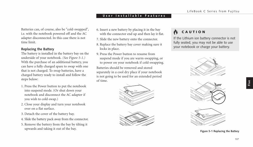
Five
U s e r I n s t a l l a b l e F e a t u r e sL i f e B o o k C S e r i e s f r o m F u j i t s u
107
Batteries can, of course, also be "cold-swapped",i.e. with the notebook powered off and the ACadapter disconnected. In this case there is nottime limit.
Replacing the BatteryThe battery is installed in the battery bay on theunderside of your notebook. (See Figure 5-1.)With the purchase of an additional battery, youcan have a fully charged spare to swap with onethat is not charged. To swap batteries, have acharged battery ready to install and follow thesteps below:
1. Press the Power button to put the notebookinto suspend mode. (Or shut down yournotebook and disconnect the AC adapter ifyou wish to cold-swap.)
2. Close your display and turn your notebookover on a flat surface.
3. Detach the cover of the battery bay.
4. Slide the battery pack away from the connector.
5. Remove the battery from the bay by tilting itupwards and taking it out of the bay.
Figure 5-1 Replacing the Battery
6. Insert a new battery by placing it in the baywith the connector end up and then lay it flat.
7. Slide the new battery onto the connector.
8. Replace the battery bay cover making sure itlocks in place.
9. Press the Power button to resume fromsuspend mode if you are warm-swapping, orto power on your notebook if cold-swapping.
Batteries should be removed and storedseparately in a cool dry place if your notebookis not going to be used for an extended period of time.
C A U T I O N
If the Lithium ion battery connector is notfully seated, you may not be able to useyour notebook or charge your battery.
S e c t i o n F i v e
108
C A U T I O N
Do not insert a PC Card into a slot if thereis water or any other substance on thecard; you may permanently damage thecard, your notebook, or both.
■ Do not force cards into the slot.
■ Avoid dropping cards, or subjecting them to excessive vibration.
Installing PC Cards in Your NotebookPC cards are installed in the PC Card slots in theleft side panel of your notebook. Some PC Cardswill not work when all possible devices are enabled. If a PC Card is not recognized, you may need to open the Control panel, the Systemfolder, and then the Device Manager, and choosea device to disable so that the resources can beused by the PC Card.
PC CARDSPC Cards perform a wide variety of functions,and are ideal for mobile computers.
Some available PC Cards:
■ Fax/data modem cards (Type II).
■ Local area network (LAN) cards (Type II).
■ Wireless LAN cards (Type II).
■ IDE solid-state disk cards (Type II).
■ SCSI cards (Type II).
■ Zoomed Video cards (Type II, bottomslot only).
■ ATA cards (Type III).
■ Other PC Cards that conform to PCMCIA2.1 or CardBus standards.
For further information, refer to the instruc-tions supplied with your PC Card.
Caring for PC Cards PC Cards are durable; however, you must treatthem with care. The documentation suppliedwith your PC Card will provide specific infor-mation but you should pay attention to the following points:
■ To keep out dust and dirt, store PC Cards in their protective sleeves when they are notinstalled in your notebook.
■ Avoid prolonged exposure to direct sunlightor excessive heat.
■ Keep the cards dry.
■ Do not flex or bend the cards, and do notplace heavy objects on top of them.
P O I N T
Under federal, state or local law it may beillegal to dispose of batteries by puttingthem in the trash. Please take care of ourenvironment and dispose of batteriesproperly. Check with your local govern-ment authority for details regarding recy-cling or disposing of your old battery, orcontact your support representative at1-800-8FUJITSU (1-800-838-5487).

Five
U s e r I n s t a l l a b l e F e a t u r e sL i f e B o o k C S e r i e s f r o m F u j i t s u
109
To install a PC Card:1. See your PC Card manual for instructions on
installation of that specific card.
2. Make sure that there is not already a PCCard in the slot. If there is, eject it, asdescribed in Removing PC Cards.
C A U T I O N
Some PC Cards can only be installed orremoved with the power Off. Please checkthe card documentation for correct usage.
3. Insert the PC Card in the card slot, with theproduct name label facing up. (Figure 5-2.)
4. When the PC Card is fully inserted, the ejectbutton will pop out.
5. Flip this button toward the front of yournotebook to fold it out of the way.
6. When the card is installed, lock it in place by sliding the Lock button toward the frontof your notebook. (Figure 5-2.)
Figure 5-2 Installing and Removing a PC Card
C A U T I O N
Installing or removing a card while yournotebook is in the process of goingthrough the power on or power offsequence may damage the card and/oryour notebook.
C A U T I O N
Windows 98 has a shutdown procedurefor PC Cards that must be followedbefore beginning to remove a card.

S e c t i o n F i v e
110
PARALLEL PORT DEVICESTo connect a parallel interface device to the par-allel port, be sure that the connector is the rightsize and aligned, then push in until it is fullyseated. When it is seated, tighten the hold-downscrew on each end of the connector.(See Figure 1-6 on page 8.)
SERIAL PORT DEVICESTo connect an RS-232C device to the serialport, be sure that the connector is the right sizeand aligned, then push in until it is fully seated.When it is seated, tighten the hold-down screwon each end of the connector.(See Figure 1-6 on page 8.)
USB DEVICESWhen installing a device on the USB Port, besure that the connector is the right size, aligned,and fully seated. (See Figure 1-6 on page 8.)
Removing PC CardsIf you wish to remove or replace the PC Card,use the following procedure:
1. Close applications that are using the PC Card.
2. Double-click on the PC Card indicator onthe Windows taskbar.
From the PC Card Properties Window:
3. Select the card to be removed and click on the Stop button.
4. Verify that the You can safely removeyour card message appears.
5. Remove the card.
6. If the device cannot be removedmessage appears, save all files, close all applications, and exit Windows 98 thenshutoff the power with the power switch.(See Power Off on pages 20-21.)
7. Remove the card.
C A U T I O N
If the PC Card has an external connectorand cable, do not pull on this cable whenremoving the card.
MICROPHONEMake sure that your mono microphone isequipped with an 1/8" (3.5 mm) mono mini-plug. Make sure the plug is aligned and push itinto the jack until fully seated. (See Figure 1-5on page 7.)
STEREO LINE IN DEVICEMake sure that your stereo line in audio device,a cassette recorder, for example, is equippedwith an 1/8" (3.5 mm) stereo mini-plug. Makesure the plug is aligned and push it into the jackuntil fully seated. (See Figure 1-5 on page 7.)
HEADPHONESMake sure that your stereo headphones areequipped with an 1/8" (3.5 mm) stereo mini-plug. Make sure the plug is aligned and push it into the jack until fully seated.(See Figure 1-5 on page 7.)
P O I N T
Plugging in headphones disables thebuilt-in stereo speakers.
Five
U s e r I n s t a l l a b l e F e a t u r e sL i f e B o o k C S e r i e s f r o m F u j i t s u
111
C A U T I O N
The internal modem is not intended foruse with Digital PBX systems. Do notconnect the internal modem to a digitalPBX as it may cause serious damage tothe internal modem or your entire note-book. Consult your PBX manufacturer’sdocumentation for details. Some hotelshave Digital PBX systems. Be sure to findout BEFORE you connect your modem.
TELEPHONE LINESTo attach a telephone line to the internalmodem open the rear panel connector cover orwith the cover closed slide the panel in the con-nector cover slightly opened to reveal theModem(RJ-11) jack. Plug one end of the tele-phone cable into the telephone line outlet.Orient the telephone cable with the release latchon the connector up. Push it into the jack untilit clicks and latches. (See Figure 1-6 on page 8.)
MOUSE, KEYBOARD OR KEYPADMake sure the connector on your device is the correct PS/2 type. Align the arrow on theconnector to point to the bottom of your note-book and push it in until the connector seats.A mouse, keyboard or keypad may be installedand automatically recognized by your notebookwithout restarting or changing setups.(See Figure 1-5 on page 7.)
EXTERNAL MONITORYou may install an external monitor on theexternal monitor port on the rear panel of yournotebook. Make sure that the wide side of theconnector is up and attach it to the port bypushing in until it is seated, then tighten thehold-down screw on each end of the connector.(See Figure 1-6 on page 8.)
C A U T I O N
Pressing F10 while holding down the Fnkey allows you to change your selection of where to send your display video. Eachtime you press the combination of keysyou will step to the next choice. Thechoices, in order, are: built-in display panelonly, external monitor only, or both built-indisplay panel and external monitor.
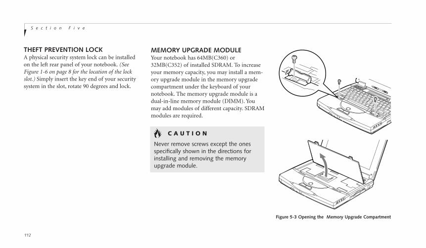
S e c t i o n F i v e
112
MEMORY UPGRADE MODULEYour notebook has 64MB(C360) or32MB(C352) of installed SDRAM. To increaseyour memory capacity, you may install a mem-ory upgrade module in the memory upgradecompartment under the keyboard of yournotebook. The memory upgrade module is adual-in-line memory module (DIMM). Youmay add modules of different capacity. SDRAMmodules are required.
C A U T I O N
Never remove screws except the onesspecifically shown in the directions forinstalling and removing the memoryupgrade module.
Figure 5-3 Opening the Memory Upgrade Compartment
THEFT PREVENTION LOCKA physical security system lock can be installedon the left rear panel of your notebook. (SeeFigure 1-6 on page 8 for the location of the lockslot.) Simply insert the key end of your security system in the slot, rotate 90 degrees and lock.

Five
U s e r I n s t a l l a b l e F e a t u r e sL i f e B o o k C S e r i e s f r o m F u j i t s u
113
C A U T I O N
The memory upgrade module can beseverely damaged by electro-staticdischarge (ESD). Be sure you areproperly grounded when handlingand installing the module.
4. Align the memory upgrade module with thechip side up. Align the connector edge of thememory upgrade module with the connectorslot in the compartment. The connector willbe pointing toward you. (Figure 5-4.)
5. Insert the memory upgrade module at a 45° angle. (Figure 5-4.) Press the connectoredge of the module firmly down and intothe connector.
6. Press the memory upgrade module downinto the compartment until it lodges underthe retaining clip. You will hear a click whenit is properly in place.
7. Close the keyboard –making sure that thetabs at the back seat properly into their slots–until flush with your notebook. (Figure 5-5.)
8. Replace the screws and the keyboardlock covers.
To Install a Memory Upgrade Module:1. Shut Down your notebook (see Power Off on
pages 20-21) and remove any power adapter(AC or auto/airline).
2. Open and remove the keyboard lock coverson both sides of the keyboard, and removethe screws. (Figure 5-3.)
3. Open the keyboard slowly, using the lift tabson either side, which were uncovered inStep two. (Figure 5-3.) Figure 5-4 Installing a Memory Upgrade Module
Figure 5-5 Closing the Memory Upgrade Compartment

S e c t i o n F i v e
114
To Remove a Memory Upgrade Module:1. Perform steps 1 through 3 of To Install a
Memory Upgrade Module.
2. Pull the clips sideways away from eachside of the memory upgrade module atthe same time.
3. While holding the clips out, remove themodule from the slot by lifting it up andpulling towards the front of your notebook.
4. Store the memory upgrade module in a staticguarded sleeve.
5. Close the keyboard by following the instruc-tions in steps 7 and 8 of the instructions for To Install a Memory Upgrade Module.
The memory upgrade module is not somethingyou routinely remove from your notebook.Once it is installed, you should leave it in place unless you want to increase system memory capacity.
C A U T I O N
Before you install or remove the memoryupgrade module, save changes and closeall files and turn power off to your note-book. (See Power Off on pages 20-21.)
Checking the Computer Recognition of New Memory CapacityWhen you have changed system memorycapacity by adding or removing a memoryupgrade module, be sure to check that yournotebook has recognized all of the memory.You can check memory capacity by looking atthe Main menu of the setup utility:
1. Turn on power using the power switch.
2. Enter the setup utility by pressing the F2 keyas soon as the Fujitsu logo appears on thescreen. (See page 49.)
3. The System Memory and the ExtendedMemory capacity, as detected by your note-book during the Power On Self Test (POST),are displayed at the bottom of the Mainmenu screen.
Example: A system with 32MB of memory will display 640K System Memory, 31MExtended Memory.
P O I N T
After installing your added memory mod-ule, you must complete the Resetting theSave-to-Disk Parameters procedure inorder for the Save-to-Disk mode to operate properly on your LifeBook.(See page 115)

Five
U s e r I n s t a l l a b l e F e a t u r e sL i f e B o o k C S e r i e s f r o m F u j i t s u
115
When you have installed additional memory,the display should change. For example for:
Total RAM System ExtendedInstalled Memory Memory32 MB 640 K 31M48 MB 640 K 47M64 MB 640 K 63M96 MB 640 K 95M128MB 640 K 127M
If the total memory displayed is not what youbelieve it should be, check that your memoryupgrade module is properly installed. If it isproperly installed and the capacity is notcorrectly recognized, see the TroubleshootingSection starting on page 118.
T r o u b l e s h o o t i n gS e c t i o n S i x
Identifying the Problem . . . . . . . . . . . 118
Specific Problems . . . . . . . . . . . . . . 119
Power On Self Test Messages . . . . . . . . 138
Emergency CD-ROMTray Release . . . . . . . . . . . . . . . 141
Modem Setup and Commands . . . . . . . 141
Recovery CD-ROM . . . . . . . . . . . . . 142
S e c t i o n S i x
118
SECTION SIXTROUBLESHOOTINGThe LifeBook C Series from Fujitsu is sturdy and subject to few problems in the field.However, you may encounter simple setup oroperating problems that you can solve on thespot, or problems with peripheral devices, thatyou can solve by replacing the device. The infor-mation in this section helps you isolate andresolve some of these straightforward problems,and identify failures that require service.
IDENTIFYING THE PROBLEMIf you encounter a problem, go through the following procedure before pursuingcomplex troubleshooting:
1. Make sure the AC adapter is plugged into your notebook and to an active ACpower source.
2. Make sure that any card installed in the PC Card slot is seated properly. You can
also remove the card from the slot, thus eliminating it as a possible cause of failure.
3. Make sure that any devices connected to the external connectors are plugged in properly. You can also disconnect suchdevices, thus eliminating them as possiblecauses of failure.
4. Go through the boot sequence.(See Section 2, pages 14-15.)
5. If the problem has not been resolved, refer to the problem guide table, which follows, formore detailed troubleshooting information.(See page 119.)
C A U T I O N
Do not return a failed notebook to your supplier until you have talked to a support representative.
P O I N T
If you keep notes about what you havetried, your support representative may beable to help you more quickly by givingadditional suggestions over the phone.
6. If you have tried the solutions suggested inSpecific Problems without success, contactyour support representative:toll free 1-800-8FUJITSU (1-800-838-5487)fax 1-901-259-5700 e-mail [email protected] Web Site http://www.8fujitsu.com.
Before you place the call, you should have the following information ready so that the customer support representative can provideyou with the fastest possible solution:
■ Product name.
■ Product configuration number.
■ Product serial number.
■ Purchase date.
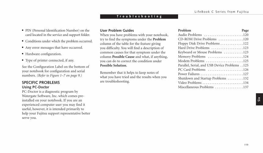
Six
T r o u b l e s h o o t i n gL i f e B o o k C S e r i e s f r o m F u j i t s u
119
■ PIN (Personal Identification Number) on thecard located in the service and support folder.
■ Conditions under which the problem occurred.
■ Any error messages that have occurred.
■ Hardware configuration.
■ Type of printer connected, if any.
See the Configuration Label on the bottom ofyour notebook for configuration and serialnumbers. (Refer to Figure 1–7 on page 9.)
SPECIFIC PROBLEMSUsing PC-DoctorPC-Doctor is a diagnostic program by Watergate Software, Inc. which comes pre-installed on your notebook. If you are an experienced computer user you may find it useful, however, it is intended primarily to help your Fujitsu support representative betterserve you.
User Problem GuidesWhen you have problems with your notebook,try to find the symptoms under the Problemcolumn of the table for the feature giving you difficulty. You will find a description ofcommon causes for that symptom under thecolumn Possible Cause and what, if anything,you can do to correct the condition underPossible Solution.
Remember that it helps to keep notes ofwhat you have tried and the results when youare troubleshooting.
Problem PageAudio Problems . . . . . . . . . . . . . . . . . . . . . .120CD-ROM Drive Problems . . . . . . . . . . . . . .120Floppy Disk Drive Problems . . . . . . . . . . . . .122Hard Drive Problems . . . . . . . . . . . . . . . . . .123Keyboard or Mouse Problems . . . . . . . . . . .123Memory Problems . . . . . . . . . . . . . . . . . . . .124Modem Problems . . . . . . . . . . . . . . . . . . . . .125Parallel, Serial, and USB Device Problems . .125PC Card Problems . . . . . . . . . . . . . . . . . . . .126Power Failures . . . . . . . . . . . . . . . . . . . . . . . .127Shutdown and Startup Problems . . . . . . . . .132Video Problems . . . . . . . . . . . . . . . . . . . . . . .134Miscellaneous Problems . . . . . . . . . . . . . . . .137
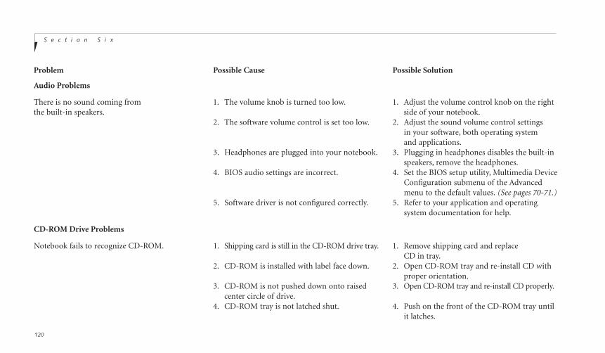
S e c t i o n S i x
120
Audio Problems
There is no sound coming from 1. The volume knob is turned too low. 1. Adjust the volume control knob on the rightthe built-in speakers. side of your notebook.
2. The software volume control is set too low. 2. Adjust the sound volume control settings in your software, both operating systemand applications.
3. Headphones are plugged into your notebook. 3. Plugging in headphones disables the built-inspeakers, remove the headphones.
4. BIOS audio settings are incorrect. 4. Set the BIOS setup utility, Multimedia Device Configuration submenu of the Advanced menu to the default values. (See pages 70-71.)
5. Software driver is not configured correctly. 5. Refer to your application and operating system documentation for help.
CD-ROM Drive Problems
Notebook fails to recognize CD-ROM. 1. Shipping card is still in the CD-ROM drive tray. 1. Remove shipping card and replace CD in tray.
2. CD-ROM is installed with label face down. 2. Open CD-ROM tray and re-install CD with proper orientation.
3. CD-ROM is not pushed down onto raised 3. Open CD-ROM tray and re-install CD properly.center circle of drive.
4. CD-ROM tray is not latched shut. 4. Push on the front of the CD-ROM tray untilit latches.
Problem Possible Cause Possible Solution

T r o u b l e s h o o t i n gL i f e B o o k C S e r i e s f r o m F u j i t s u
121
Notebook fails to recognize CD-ROM (continued). 5. Setup utility is set to something other than 5. Revise BIOS settings to set the SecondaryCD-ROM or Auto for the Secondary Master correctly. (See Main menu andMaster Controller. Primary Master submenu pages 52-57 for
more information.)6. Wrong drive designator was used for 6. Verify the drive designator used by the
CD-ROM in the application. application is the same as the one used bythe operating system. When the operatingsystem is booted from a CD-ROM drivedesignations are automatically adjusted.(See Boot Options submenu on pages 95-96.)
7. Windows CD auto insertion function 7. Start the CD from the desktop or is disabled. application software or re-enable the
Windows CD auto insertion function.(See CD-ROM Access Indicator on pages 22-24 for more information.)
The CD-ROM Access indicator on the Status 1. The Windows CD auto insertion function 1. This is normal. You can disable this functionIndicator panel blinks at regular intervals when is active and is checking to see if a CD is if you wish. (See CD-ROM Access Indicatorno CD is in the tray or the CD-ROM drive is ready to run. on pages 22-24 for more information.)not installed.
Problem Possible Cause Possible Solution
Six
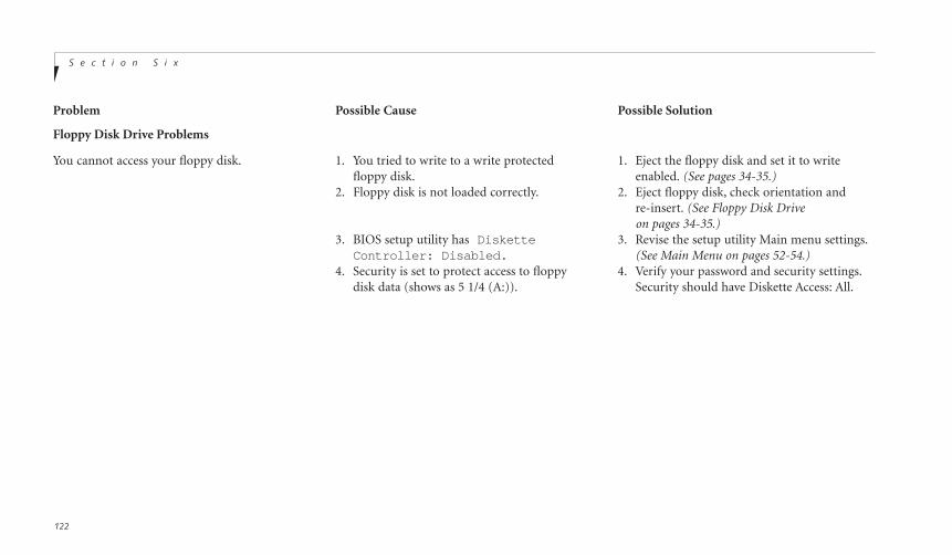
S e c t i o n S i x
122
Problem Possible Cause Possible Solution
Floppy Disk Drive Problems
You cannot access your floppy disk. 1. You tried to write to a write protected 1. Eject the floppy disk and set it to writefloppy disk. enabled. (See pages 34-35.)
2. Floppy disk is not loaded correctly. 2. Eject floppy disk, check orientation and re-insert. (See Floppy Disk Drive on pages 34-35.)
3. BIOS setup utility has Diskette 3. Revise the setup utility Main menu settings.Controller: Disabled. (See Main Menu on pages 52-54.)
4. Security is set to protect access to floppy 4. Verify your password and security settings.disk data (shows as 5 1/4 (A:)). Security should have Diskette Access: All.

T r o u b l e s h o o t i n gL i f e B o o k C S e r i e s f r o m F u j i t s u
123
Problem Possible Cause Possible Solution
Six
Hard Drive Problems
You can not access your hard drive. 1. The setup utility is set to something other 1. Revise BIOS settings to set both Primarythan the characteristics of your internal Master and Primary Slave correctly.hard drive. (See Main Menu and Primary Master
Submenu on pages 52-57 for moreinformation.)
2. The wrong drive designator was used by an 2. Verify drive designator used by application application when a bootable CD-ROM was is in use by the operating system. When the used to start the notebook. operating system is booted from a CD-ROM,
drive designations are automatically adjusted.(See Primary Master Submenu on pages 55-57.)
3. Security is set so operating system can not 3. Verify your password and security settings.be started without a password. (See Security menu on pages 80-84.)
Keyboard or Mouse Problems
The built-in keyboard does not seem to work. 1. The notebook has gone into Suspend mode. 1. Push the Suspend/Resume button.2. Your application has locked out 2. Try to use the ErgoTrac pointing device
your keyboard. to access the Start menu and then theShutDown menu and restart the System.If this fails, then reset your notebook using the reset button located on the rear panel. (See Reset button on page 21.)
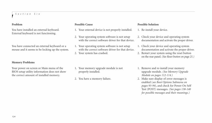
S e c t i o n S i x
124
Problem Possible Cause Possible Solution
You have installed an external keyboard. 1. Your external device is not properly installed. 1. Re-install your device.External keyboard is not functioning.
2. Your operating system software is not setup 2. Check your device and operating system with the correct software driver for that device. documentation and activate the proper driver.
You have connected an external keyboard or a 1. Your operating system software is not setup 1. Check your device and operating systemmouse and it seems to be locking up the system. with the correct software driver for that device. documentation and activate the proper driver.
2. Your system has crashed. 2. Restart your system using the reset button on the rear panel. (See Reset button on page 21.)
Memory Problems
Your power on screen or Main menu of the 1. Your memory upgrade module is not 1. Remove and re-install your memory BIOS setup utility information does not show properly installed. upgrade module. (See Memory Upgrade the correct amount of installed memory. Module on pages 112-114.)
2. You have a memory failure. 2. Make sure display of error messages is enabled (see Boot Options Submenu on pages 93-94), and check for Power On SelfTest (POST) messages. (See pages 138-140 for possible messages and their meanings.)

T r o u b l e s h o o t i n gL i f e B o o k C S e r i e s f r o m F u j i t s u
125
Problem Possible Cause Possible Solution
Six
Modem Problems
Messages about modem operation. 1. Messages about modem operation are 1. See your application software documenta-generated by whichever modem application tion for additional information.is in use.
Parallel, Serial, and USB Device Problems
You have installed a parallel-port device, 1. The device is not properly installed. 1. Remove and re-install the device.a serial-port device or a USB device. Your (See Parallel Port Devices, Serial Port Devicesnotebook does not recognize the device, or or USB Devices on page 110.) the device does not seem to work properly. 2. The device may have been installed with an 2. Close your application and restart
application running and your notebook your notebook.doesn’t know it’s there.
3. Your software may not have the correct 3. See your software documentation andsoftware driver active. activate the correct driver.
4. You may have the wrong I/O address 4. See your device documentation andselected for your device. software documentation to determine the
required I/O address.5. Your device and another device are 5. Check all I/O addresses in the BIOS Setup
assigned the same I/O address. Utility and your other installed hardware and software and make sure there are no duplications.
6. Parallel port is set to output only. 6. Check Parallel port settings in BIOS, and set to Bi-directional or Ecp.
C A U T I O N
Due to ongoing changes in USB technology and standards, not all USBdevices and/or drivers are guaranteed to work.
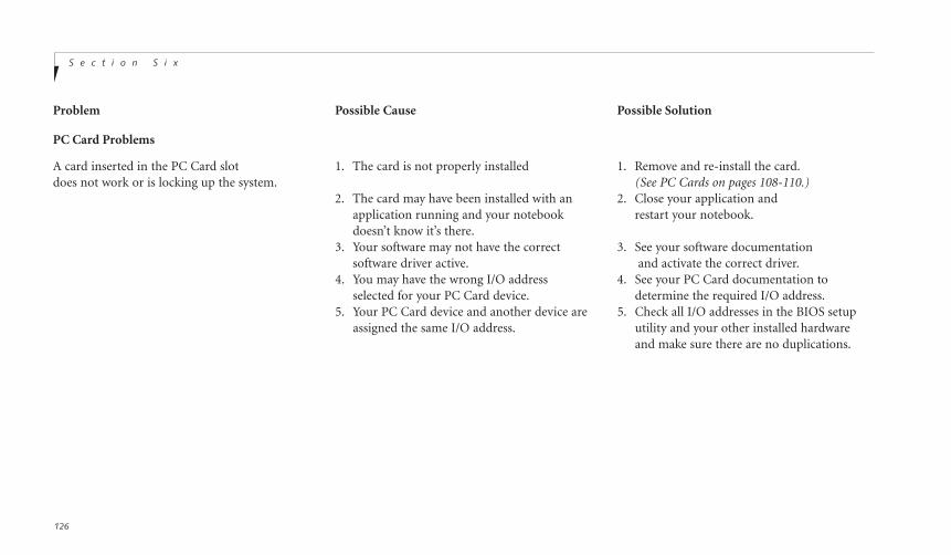
S e c t i o n S i x
126
Problem Possible Cause Possible Solution
PC Card Problems
A card inserted in the PC Card slot 1. The card is not properly installed 1. Remove and re-install the card.does not work or is locking up the system. (See PC Cards on pages 108-110.)
2. The card may have been installed with an 2. Close your application and application running and your notebook restart your notebook.doesn’t know it’s there.
3. Your software may not have the correct 3. See your software documentationsoftware driver active. and activate the correct driver.
4. You may have the wrong I/O address 4. See your PC Card documentation toselected for your PC Card device. determine the required I/O address.
5. Your PC Card device and another device are 5. Check all I/O addresses in the BIOS setupassigned the same I/O address. utility and your other installed hardware
and make sure there are no duplications.

T r o u b l e s h o o t i n gL i f e B o o k C S e r i e s f r o m F u j i t s u
127
Problem Possible Cause Possible Solution
Six
Power Failures
You turn on your notebook and 1. The installed battery is completely 1. When the battery is dead there will benothing seems to happen. discharged, and there is no Power a beep when the power is turned on
adapter (AC or auto/airline) installed. and the notebook will immediately go into Dead Battery Suspend mode. (See page 28.) Check the Status Indicator panel to determine the presence and condition ofthe battery. (See pages 22-23.) Install the battery if it is not installed or a Poweradapter if all batteries are dead orunavailable. (See pages 107-108 and 12-13.)
2. The battery is installed but is 2. When the battery is dead there will be acompletely discharged and the Power beep when the power is turned on and adapter (AC or auto/airline) is not the notebook will immediately go intoplugged in properly. Dead Battery Suspend mode. (See page 28.)
Check the Status Indicator panel to determine the presence and condition of the battery and adapter. (See Figures 3-3 and 3-4 on pages 22-23.) Verify that your adapter is connected correctly. (See pages 12-13.)
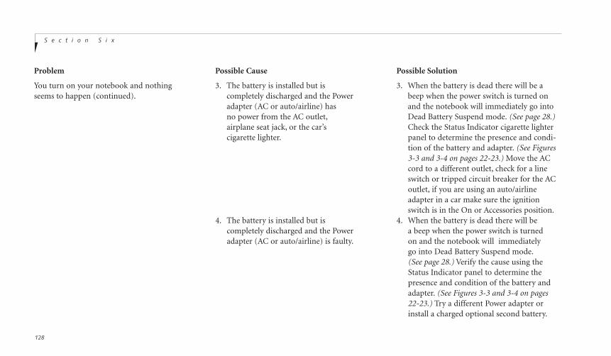
S e c t i o n S i x
128
Problem Possible Cause Possible Solution
You turn on your notebook and nothing 3. The battery is installed but is 3. When the battery is dead there will be aseems to happen (continued). completely discharged and the Power beep when the power switch is turned on
adapter (AC or auto/airline) has and the notebook will immediately go into no power from the AC outlet, Dead Battery Suspend mode. (See page 28.)airplane seat jack, or the car’s Check the Status Indicator cigarette lighter cigarette lighter. panel to determine the presence and condi-
tion of the battery and adapter. (See Figures3-3 and 3-4 on pages 22-23.) Move the AC cord to a different outlet, check for a line switch or tripped circuit breaker for the AC outlet, if you are using an auto/airline adapter in a car make sure the ignition switch is in the On or Accessories position.
4. The battery is installed but is 4. When the battery is dead there will be completely discharged and the Power a beep when the power switch is turned adapter (AC or auto/airline) is faulty. on and the notebook will immediately
go into Dead Battery Suspend mode.(See page 28.) Verify the cause using the Status Indicator panel to determine the presence and condition of the battery and adapter. (See Figures 3-3 and 3-4 on pages 22-23.) Try a different Power adapter orinstall a charged optional second battery.
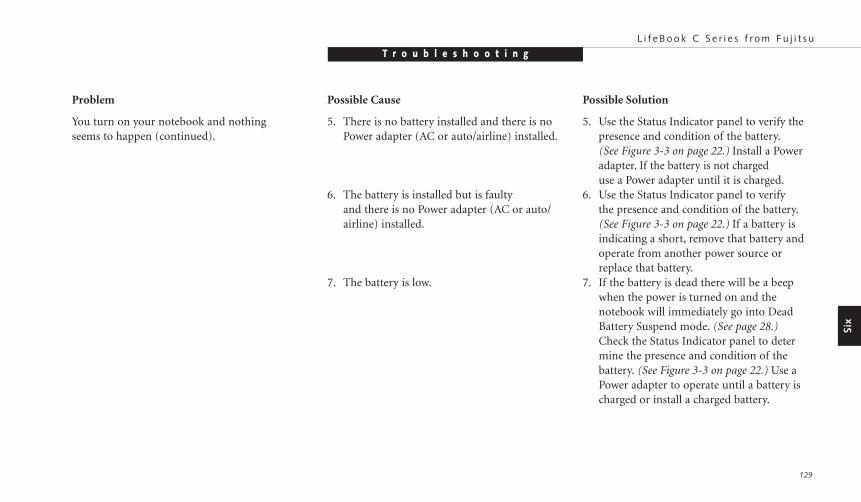
T r o u b l e s h o o t i n gL i f e B o o k C S e r i e s f r o m F u j i t s u
129
Problem Possible Cause Possible Solution
Six
You turn on your notebook and nothing 5. There is no battery installed and there is no 5. Use the Status Indicator panel to verify theseems to happen (continued). Power adapter (AC or auto/airline) installed. presence and condition of the battery.
(See Figure 3-3 on page 22.) Install a Power adapter. If the battery is not charged use a Power adapter until it is charged.
6. The battery is installed but is faulty 6. Use the Status Indicator panel to verify and there is no Power adapter (AC or auto/ the presence and condition of the battery.airline) installed. (See Figure 3-3 on page 22.) If a battery is
indicating a short, remove that battery and operate from another power source or replace that battery.
7. The battery is low. 7. If the battery is dead there will be a beep when the power is turned on and the notebook will immediately go into Dead Battery Suspend mode. (See page 28.)Check the Status Indicator panel to determine the presence and condition of the battery. (See Figure 3-3 on page 22.) Use a Power adapter to operate until a battery is charged or install a charged battery.
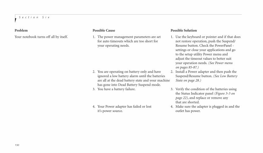
S e c t i o n S i x
130
Problem Possible Cause Possible Solution
Your notebook turns off all by itself. 1. The power management parameters are set 1. Use the keyboard or pointer and if that doesfor auto timeouts which are too short for not restore operation, push the Suspend/ your operating needs. Resume button. Check the PowerPanel -
settings or close your applications and go to the setup utility Power menu andadjust the timeout values to better suit your operation needs. (See Power menu on pages 85-87.)
2. You are operating on battery only and have 2. Install a Power adapter and then push theignored a low battery alarm until the batteries Suspend/Resume button. (See Low Batteryare all at the dead battery state and your machine State on page 28.)has gone into Dead Battery Suspend mode.
3. You have a battery failure. 3. Verify the condition of the batteries using the Status Indicator panel (Figure 3-3 on page 22), and replace or remove any that are shorted.
4. Your Power adapter has failed or lost 4. Make sure the adapter is plugged in and theit’s power source. outlet has power.
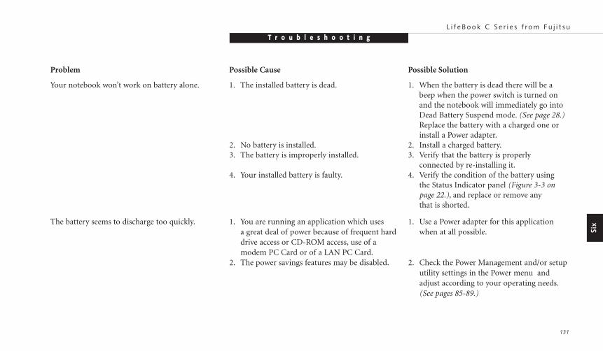
T r o u b l e s h o o t i n gL i f e B o o k C S e r i e s f r o m F u j i t s u
131
Problem Possible Cause Possible Solution
Six
Your notebook won’t work on battery alone. 1. The installed battery is dead. 1. When the battery is dead there will be a beep when the power switch is turned onand the notebook will immediately go intoDead Battery Suspend mode. (See page 28.)Replace the battery with a charged one or install a Power adapter.
2. No battery is installed. 2. Install a charged battery.3. The battery is improperly installed. 3. Verify that the battery is properly
connected by re-installing it.4. Your installed battery is faulty. 4. Verify the condition of the battery using
the Status Indicator panel (Figure 3-3 on page 22.), and replace or remove any that is shorted.
The battery seems to discharge too quickly. 1. You are running an application which uses 1. Use a Power adapter for this application a great deal of power because of frequent hard when at all possible.drive access or CD-ROM access, use of a modem PC Card or of a LAN PC Card.
2. The power savings features may be disabled. 2. Check the Power Management and/or setup utility settings in the Power menu and adjust according to your operating needs.(See pages 85-89.)

S e c t i o n S i x
132
Problem Possible Cause Possible Solution
The battery seems to discharge 3. The brightness is turned all the way up. 3. Turn down the brightness adjustment. The too quickly (continued). higher the brightness the more power your
display uses.4. The battery has been exposed to 4. Replace the battery.
high temperatures.5. The battery is too hot or too cold. 5. Restore the notebook to normal operating
(See Batteries on page 26.) temperature. (The Charging icon on the Status Indicator panel will flash when the battery is outside its operating range.)
Shutdown and Startup Problems
The Power button does not work. 1. The Power button is disabled from 1. Enable the button from the setup utility.the Advanced submenu of the Power menu (See page 91.)of the setup utility.
2. You did not hold the button in long enough. 2. Hold the button longer. This may need to be a very long time if your application is preventing the CPU from checking for button pushes.
3. There may be a conflict with the 3. Close all applications, and try the application software. button again.

Six
T r o u b l e s h o o t i n gL i f e B o o k C S e r i e s f r o m F u j i t s u
133
Problem Possible Cause Possible Solution
The system powers up, and displays 1. The boot sequence settings of the setup utility 1. Set the operating source by pressing the Escpower on information, but fails to load are not compatible with your configuration. key while the Fujitsu logo is on screen or usethe operating system. the F2 key and enter the setup utility and
adjust the source settings from the Boot menu on page 94.
2. You have a secured system requiring a 2. Make sure you have the right password.password to load your operating system. Enter the setup utility and verify the
Security settings and modify them as appro-priate. (See Security Menu on pages 80-84.)
3. Internal hard drive was not detected. 3. Use the BIOS setup utility Main menu,Primary Master submenu to try to auto detect the internal hard drive.
An error message is displayed on the screen 1. Power On Self Test (POST) has detected 1. See the Power On Self Test (POST) Messagesduring the notebook turn on (boot) sequence. a problem. (See pages 138-140), to determine the meaning
and severity of the problem. Not all messagesare errors; some are simply status indicators.
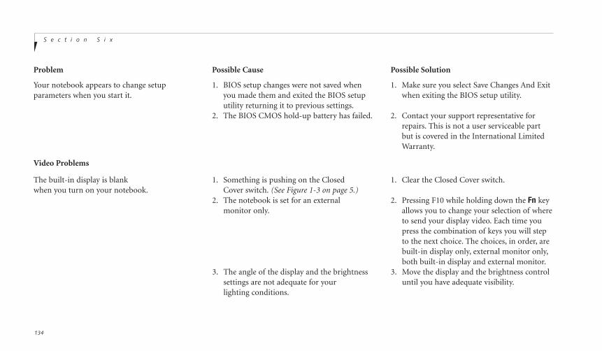
S e c t i o n S i x
134
Problem Possible Cause Possible Solution
Your notebook appears to change setup 1. BIOS setup changes were not saved when 1. Make sure you select Save Changes And Exit parameters when you start it. you made them and exited the BIOS setup when exiting the BIOS setup utility.
utility returning it to previous settings.2. The BIOS CMOS hold-up battery has failed. 2. Contact your support representative for
repairs. This is not a user serviceable part but is covered in the International Limited Warranty.
Video Problems
The built-in display is blank 1. Something is pushing on the Closed 1. Clear the Closed Cover switch.when you turn on your notebook. Cover switch. (See Figure 1-3 on page 5.)
2. The notebook is set for an external 2. Pressing F10 while holding down the Fn keymonitor only. allows you to change your selection of where
to send your display video. Each time you press the combination of keys you will step to the next choice. The choices, in order, are built-in display only, external monitor only,both built-in display and external monitor.
3. The angle of the display and the brightness 3. Move the display and the brightness controlsettings are not adequate for your until you have adequate visibility.lighting conditions.
T r o u b l e s h o o t i n gL i f e B o o k C S e r i e s f r o m F u j i t s u
135
Problem Possible Cause Possible Solution
Six
The built-in display is blank 4. The power management timeouts may be 4. Press any key or move the pointer, if thisparameters when you start it (continued.) set for very short intervals and you failed to doesn’t work press the Suspend/Resume
notice the display come on and go off again. button. (The display may be shut offby Standby mode, Auto Suspend, or Video Timeout.)
5. The notebook turned on with a series of beeps. 5. Power On Self Test (POST) has detected a failure which does not allow the display to operate. Contact your support representative.
The display goes blank by itself after you 1. The notebook has gone into Video timeout, 1. Use the keyboard or pointer and ifhave been using it. Standby mode, Suspend mode or Save-to-Disk that does not restore operation, push the
mode because you have not used it for a Suspend/Resume button. You may want period of time. to close your application and go
to the setup utility Power menu (See pages 85-87), and adjust the timeoutvalues to better suit your operation needs.
2. Something is pushing on the Closed 2. Clear the Closed Cover switch.Cover switch. (See Figure 1-3 on page 5.)
3. The power management timeouts may be set 3. Press any key or move the pointer,for very short intervals and you failed to notice if this doesn’t work press the the display come on and go off again. Suspend/Resume button.
S e c t i o n S i x
136
Problem Possible Cause Possible Solution
The Built-in Display does not close. 1. A foreign object, such as a paper clip, is stuck 1. Remove all foreign objects frombetween the display and the keyboard. the keyboard.
The Built-in Display has bright or dark spots. 1. If the spots are very tiny and few in number, 1. This is normal; do nothing.this is normal for a large LCD display.
2. If the spots are numerous or large enough to 2. Display may be faulty; contact your interfere with your operation needs. support representative.
The application display uses only a portion 1. You are running an application that does not 1. Display compression gives a clearer but of your screen and is surrounded by a dark band. support 800 x 600 pixel resolution display smaller display for applications that do not
and display compression is enabled. support 800 x 600 pixel resolution. You can fill the screen but have less resolution by changing your display compression setting,(See Video Features Submenu of the Advanced Menu on pages 72-73.)
You have connected an external monitor 1. Your BIOS setup is not set to enable your 1. Try toggling the video destination by and it does not come on. external monitor. pressing Fn and F10 together or check your
BIOS setup and enable your external moni-tor. (See the Video Features Submenu of the Advanced Menu on pages 72-73.)
2. Your external monitor is not 2. Reinstall your device.properly installed. (See External Monitor on page 111.)
T r o u b l e s h o o t i n gL i f e B o o k C S e r i e s f r o m F u j i t s u
137
You have connected an external monitor 3. Your operating system software is not setup 3 Check your device and operating systemand it does not come on (continued). with the correct software driver for that device. documentation and activate the proper driver.
4. Your external monitor is not compatible 4. See your monitor documentation and thewith your notebook. External Monitor Support portions of
Appendix A on pages 150.
Miscellaneous Problems
An error message is displayed on the screen 1. Application software often has its own 1. See your application manual and helpduring the operation of an application. set of error message displays. displays screens for more information.
Not all messages are errors; some may simply be status.
Problem Possible Cause Possible Solution
Six
S e c t i o n S i x
138
POWER ON SELF TEST MESSAGESThe following is an alphabetic list of error-and-status messages that Phoenix BIOS and/or youroperating system can generate and an explana-tion of each message. Error messages aremarked with an *. Comments in italics are sug-gestions of possible actions for you to consider,or risks resulting from ignoring the message.The most common errors are marked with a #.If an error message is displayed that is not inthis list, write it down and check your operatingsystem documentation both on screen and inthe manual. If you can find no reference to themessage and its meaning is not clear, contactyour support representative for assistance.
nnnn Cache SRAM Passed Where nnnn is theamount of system cache in kilobytes success-fully tested by the Power On Self Test. (Thiscan only appear if you have an SRAM PCCard installed.)
*Diskette drive A error or Diskette drive B error Drive A: or B: is present but fails theBIOS Power On Self Test diskette tests. Check
to see that the drive is defined with the properdiskette type in the Utility Setup (see page 53).If the disk drive is properly defined andinstalled, avoid using it and contact your support representative.
*Extended RAM Failed at offset: nnnnExtended memory not working or not config-ured properly. If you have an installed memoryupgrade module, verify that the module isproperly installed. If it is properly installed, youmay want to check your Windows Setup to besure it is not using unavailable memory untilyou can contact your support representative.
nnnn Extended RAM Passed Where nnnnis the amount of memory in kilobytessuccessfully tested.
*Failing Bits: nnnn The hex number nnnnis a map of the bits at the memory address (inSystem, Extended, or Shadow memory) whichfailed the memory test. Each 1 (one) in the mapindicates a failed bit. This is a serious fault thatmight cause you to lose data if you continue.Contact your support representative.
*Fixed Disk x Failure or Fixed Disk ControllerFailure (where x = 1-4) Fixed disk is not work-ing or not configured properly. This may meanthat the hard drive type identified in your SetupUtility does not agree with the type detected bythe Power On Self Test. Run the Setup Utilityto check for the hard drive type settings andcorrect them if necessary. If the settings are OK and the message appears when you restartthe system, there may be a serious fault whichmight cause you to lose data if you continue.Contact your support representative.
*Incorrect Drive A type – run SETUP Type offloppy drive A: not correctly identified in Setup.This means that the floppy disk drive type iden-tified in your Setup Utility does not agree withthe type detected by the Power On Self Test. Runthe Setup Utility to correct the inconsistency.
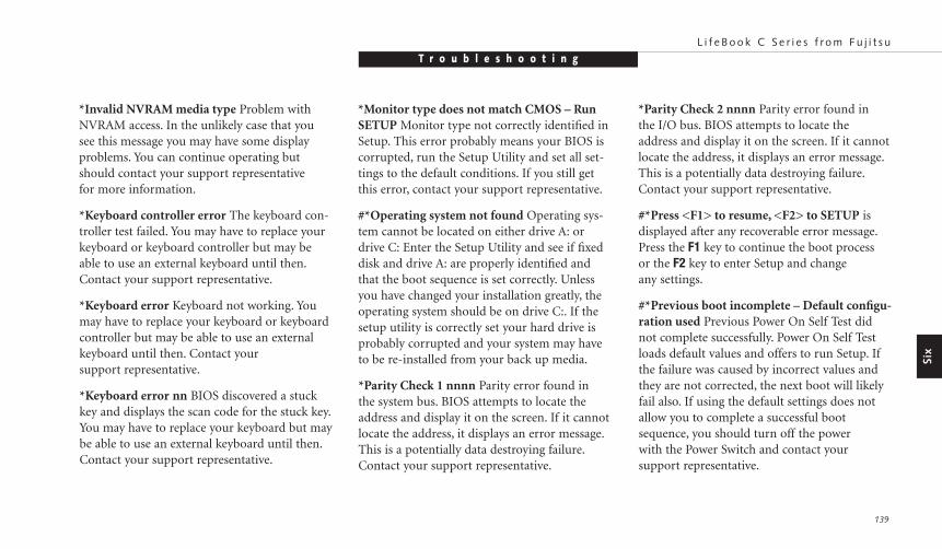
T r o u b l e s h o o t i n gL i f e B o o k C S e r i e s f r o m F u j i t s u
139
Six
*Monitor type does not match CMOS – RunSETUP Monitor type not correctly identified inSetup. This error probably means your BIOS iscorrupted, run the Setup Utility and set all set-tings to the default conditions. If you still getthis error, contact your support representative.
#*Operating system not found Operating sys-tem cannot be located on either drive A: ordrive C: Enter the Setup Utility and see if fixeddisk and drive A: are properly identified andthat the boot sequence is set correctly. Unlessyou have changed your installation greatly, theoperating system should be on drive C:. If thesetup utility is correctly set your hard drive isprobably corrupted and your system may haveto be re-installed from your back up media.
*Parity Check 1 nnnn Parity error found in the system bus. BIOS attempts to locate theaddress and display it on the screen. If it cannotlocate the address, it displays an error message.This is a potentially data destroying failure.Contact your support representative.
*Invalid NVRAM media type Problem withNVRAM access. In the unlikely case that yousee this message you may have some displayproblems. You can continue operating butshould contact your support representative for more information.
*Keyboard controller error The keyboard con-troller test failed. You may have to replace yourkeyboard or keyboard controller but may beable to use an external keyboard until then.Contact your support representative.
*Keyboard error Keyboard not working. Youmay have to replace your keyboard or keyboardcontroller but may be able to use an externalkeyboard until then. Contact your support representative.
*Keyboard error nn BIOS discovered a stuckkey and displays the scan code for the stuck key.You may have to replace your keyboard but maybe able to use an external keyboard until then.Contact your support representative.
*Parity Check 2 nnnn Parity error found in the I/O bus. BIOS attempts to locate the address and display it on the screen. If it cannotlocate the address, it displays an error message.This is a potentially data destroying failure.Contact your support representative.
#*Press <F1> to resume, <F2> to SETUP isdisplayed after any recoverable error message.Press the F1 key to continue the boot process or the F2 key to enter Setup and change any settings.
#*Previous boot incomplete – Default configu-ration used Previous Power On Self Test didnot complete successfully. Power On Self Testloads default values and offers to run Setup. Ifthe failure was caused by incorrect values andthey are not corrected, the next boot will likelyfail also. If using the default settings does notallow you to complete a successful bootsequence, you should turn off the powerwith the Power Switch and contact yoursupport representative.
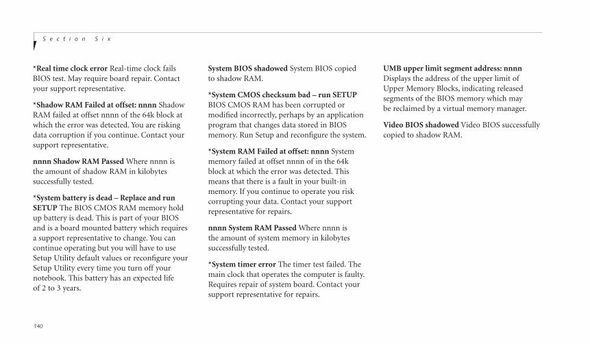
S e c t i o n S i x
140
*Real time clock error Real-time clock failsBIOS test. May require board repair. Contactyour support representative.
*Shadow RAM Failed at offset: nnnn ShadowRAM failed at offset nnnn of the 64k block atwhich the error was detected. You are riskingdata corruption if you continue. Contact yoursupport representative.
nnnn Shadow RAM Passed Where nnnn is the amount of shadow RAM in kilobytes successfully tested.
*System battery is dead – Replace and runSETUP The BIOS CMOS RAM memory holdup battery is dead. This is part of your BIOSand is a board mounted battery which requiresa support representative to change. You cancontinue operating but you will have to useSetup Utility default values or reconfigure yourSetup Utility every time you turn off yournotebook. This battery has an expected lifeof 2 to 3 years.
System BIOS shadowed System BIOS copied to shadow RAM.
*System CMOS checksum bad – run SETUPBIOS CMOS RAM has been corrupted ormodified incorrectly, perhaps by an applicationprogram that changes data stored in BIOSmemory. Run Setup and reconfigure the system.
*System RAM Failed at offset: nnnn Systemmemory failed at offset nnnn of in the 64kblock at which the error was detected. Thismeans that there is a fault in your built-inmemory. If you continue to operate you riskcorrupting your data. Contact your supportrepresentative for repairs.
nnnn System RAM Passed Where nnnn is the amount of system memory in kilobytes successfully tested.
*System timer error The timer test failed. Themain clock that operates the computer is faulty.Requires repair of system board. Contact yoursupport representative for repairs.
UMB upper limit segment address: nnnnDisplays the address of the upper limit ofUpper Memory Blocks, indicating releasedsegments of the BIOS memory which maybe reclaimed by a virtual memory manager.
Video BIOS shadowed Video BIOS successfullycopied to shadow RAM.

T r o u b l e s h o o t i n gL i f e B o o k C S e r i e s f r o m F u j i t s u
141
Six
EMERGENCY CD-ROM TRAY RELEASEIf for some reason the eject button fails, youcan open the CD-ROM tray with a paper clipor similar tool inserted into the eject hole in thefar right side of the front of the tray. Straightenone side of a paper clip and push it gently intothe hole. The tray will pop out a short distance.
Examples of result codes are:
OKNO CARRIERNO DIALTONECONNECT 56000
(Connection complete at 56,000 bps.)ERRORFAXRING (This means an incoming call.)BUSYNO ANSWER
When using the internal modem with applica-tions which are not factory installed see theapplication documentation.
Figure 6-1 Emergency CD-ROM Tray Release
MODEM SETUP AND COMMANDS
The operating system and application softwarethat is factory installed detects the modemcharacteristics and provides the necessary com-mand strings to operate the modem. The inter-nal modem operation is controlled by genericAT commands from the operating system andapplication software. The standard long formresult codes may, in some cases, be displayed onyour screen to keep you informed of the actionsof your modem. The operating system andapplication software may suppress display ofthe result codes.

C A U T I O N
User data and user installed softwareCAN NOT be recovered from theEmergency Recovery CD.
S e c t i o n S i x
142
tents as they were originally shipped from thefactory. Most often this is necessary if files orsoftware programs (only those files/programsthat came pre-installed) become corrupt oraccidentally erased.
You have two options available when performing recovery:
1. Recover Hard Drive without Format. Thischoice replaces all the original factoryinstalled files and program structures withouteliminating your data files. You will have tore-install any software that was not includedwith the computer when you bought it (butyour data will be intact as long as the installa-tion of the additional programs is performedin the same manner).
2. Format and Recover Hard Drive. This choiceremoves all the information on the hard disk.If you choose this option, you will lose anysoftware you have installed and any otherfiles you created since you setup your com-puter. You will have to re-install any softwarethat was not included with the computerwhen you bought it.
P O I N T
It is recommended that you back-up alldata files prior to performing either ofthe recovery options.
RECOVERY CD-ROMIncluded with your notebook (in theAccessories box) is an Emergency Recovery CD-ROM with the following content:
A backup copy of the software originallyinstalled by Fujitsu on your new FujitsuLifeBook (can only be used on the listedLifeBook models).
Sets of device drivers and utilities (in specificdirectories) that are unique to your notebookconfiguration for use as documented below.
Read-me files that provide additional usefulinformation for items on this CD-ROM.
If you have access to the internet, visit the Fujitsu PC Corporation Web Site atwww.8fujitsu.com to check for the most current information and hints on how to perform recovery and system updates.
Restoring Your Pre-installed Software from CD-ROMThe Emergency Recovery CD-ROM enablesrestoration of your notebook disk drive con-
P O I N T
Make certain you have your OperatingSystem Product ID # available (from theCertificate of Authenticity) prior to per-forming recovery. Once the process iscomplete and you re-start your note-book, you will be required to perform allthe setup steps as when the computerwas first bought. (See the section StartingYour LifeBook for the First Time).
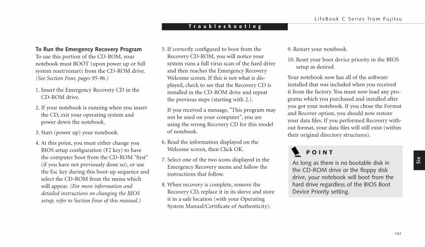
T r o u b l e s h o o t i n gL i f e B o o k C S e r i e s f r o m F u j i t s u
143
To Run the Emergency Recovery ProgramTo use this portion of the CD-ROM, your notebook must BOOT (upon power up or fullsystem reset/restart) from the CD-ROM drive.(See Section Four, pages 95-96.)
1. Insert the Emergency Recovery CD in theCD-ROM drive.
2. If your notebook is running when you insertthe CD, exit your operating system andpower down the notebook.
3. Start (power up) your notebook.
4. At this point, you must either change youBIOS setup configuration (F2 key) to havethe computer boot from the CD-ROM "first"(if you have not previously done so), or usethe Esc key during this boot-up sequence andselect the CD-ROM from the menu whichwill appear. (For more information anddetailed instructions on changing the BIOSsetup, refer to Section Four of this manual.)
5. If correctly configured to boot from theRecovery CD-ROM, you will notice your system runs a full virus scan of the hard driveand then reaches the Emergency RecoveryWelcome screen. If this is not what is dis-played, check to see that the Recovery CD isinstalled in the CD-ROM drive and repeatthe previous steps (starting with 2.).
If you received a message, "This program maynot be used on your computer", you areusing the wrong Recovery CD for this modelof notebook.
6. Read the information displayed on theWelcome screen, then Click OK.
7. Select one of the two icons displayed in theEmergency Recovery menu and follow theinstructions that follow.
8. When recovery is complete, remove theRecovery CD, replace it in its sleeve and storeit in a safe location (with your OperatingSystem Manual/Certificate of Authenticity).
Six
9. Restart your notebook.
10. Reset your boot device priority in the BIOS setup as desired.
Your notebook now has all of the softwareinstalled that was included when you received it from the factory. You must now load any pro-grams which you purchased and installed afteryou got your notebook. If you chose the Formatand Recover option, you should now restoreyour data files. If you performed Recovery with-out format, your data files will still exist (withintheir original directory structures).
P O I N T
As long as there is no bootable disk inthe CD-ROM drive or the floppy diskdrive, your notebook will boot from thehard drive regardless of the BIOS BootDevice Priority setting.

S e c t i o n S i x
144
Device Drivers, Utilities and Read-me FilesThe Emergency Recovery CD also includesdevice driver files/directories and specificLifebook model utilities that give you addition-al flexibility and functionality for using yourFujitsu notebook.
This section of the CD is only available if yournotebook is already functioning from eitheryour hard drive boot/operating system or as aresult of using a bootable floppy disk that isconfigured to recognize the CD-ROM drive.
Please locate and read any of the Read-Me filesthat are included on the CD. These files willprovide information that pertains specifically tothe additional files and utilities that are providedon the Recovery CD for your particularLifebook model.
P O I N T
As long is there is no boot disk in theCD-ROM drive or the floppy disk driveyour notebook will boot from the harddrive, regardless of the operating systemsource setting.
Your notebook now has all of the softwareinstalled that was installed when you received itfrom the factory. You must now set up the filefor your Save-to-Disk function (see Setting UpYour Save-To-Disk File Allocation starting onpage 102.), load any programs which you pur-chased and installed after you got your note-book, and restore your data files. If you did notchoose the format and recover option your datafiles will still exist. You are now ready to operate.
P O I N T
Look for and open files with theextensions .DOC and .TXT.

C a r e a n d M a i n t e n a n c eS e c t i o n S e v e n
Caring for Your Notebook. . . . . . . . . . 146
Increasing Battery Life . . . . . . . . . . . . 147
Caring for Your Batteries . . . . . . . . . . 147
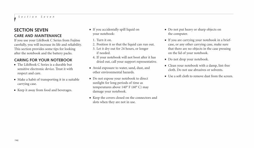
■ Do not put heavy or sharp objects on the computer.
■ If you are carrying your notebook in a brief-case, or any other carrying case, make surethat there are no objects in the case pressingon the lid of your notebook.
■ Do not drop your notebook.
■ Clean your notebook with a damp, lint-freecloth. Do not use abrasives or solvents.
■ Use a soft cloth to remove dust from the screen.
S e c t i o n S e v e n
146
SECTION SEVENCARE AND MAINTENANCEIf you use your LifeBook C Series from Fujitsucarefully, you will increase its life and reliability.This section provides some tips for lookingafter the notebook and the battery packs.
CARING FOR YOUR NOTEBOOK■ The LifeBook C Series is a durable but
sensitive electronic device. Treat it withrespect and care.
■ Make a habit of transporting it in a suitablecarrying case.
■ Keep it away from food and beverages.
■ If you accidentally spill liquid on your notebook:
1. Turn it on.2. Position it so that the liquid can run out.3. Let it dry out for 24 hours, or longer
if needed.4. If your notebook will not boot after it has
dried out, call your support representative.
■ Avoid exposure to water, sand, dust, andother environmental hazards.
■ Do not expose your notebook to direct sunlight for long periods of time as temperatures above 140° F (60° C) may damage your notebook.
■ Keep the covers closed on the connectors andslots when they are not in use.
Seve
n
C a r e a n d M a i n t e n a n c eL i f e B o o k C S e r i e s f r o m F u j i t s u
INCREASING BATTERY LIFETo increase battery life:
1. Power your notebook through the AC or optional auto/airline adapter whenever possible.
2. If your notebook is running on battery powerall day, connect it to the AC adapterovernight to recharge the battery.
3. Keep brightness to the lowest level comfortable.
4. Set the power management for maximumbattery life.
5. Put your notebook in Suspend mode when itis turned on and you are not actually using it.
6. Limit your CD-ROM and modem usage.
7. Disable the Windows 98 CD automatic insertion function. (See page 24.)
8. Always use fully charged batteries.
CARING FOR YOUR BATTERIES
If your notebook is to be stored for a month or longer, turn the machine on and remove the internal Lithium ion battery. Store yournotebook and batteries separately in a cool, drylocation. If you store your notebook with a bat-tery installed, the battery will discharge, andbattery life will be reduced. In addition, a faultybattery might damage your notebook.
147

S p e c i f i c a t i o n s a n d G l o s s a r yA p p e n d i c e s
Appendix A Specifications . . . . . . . . . 150
Warranty . . . . . . . . . . . . . . . . . . 150
LifeBook C Series Specifications . . . . . . . 150
Approvals . . . . . . . . . . . . . . . . . . 153
Popular Accessories . . . . . . . . . . . . . 153
Appendix B Glossary . . . . . . . . . . . . 154

A p p e n d i c e s
150
APPENDIX A SPECIFICATIONSAppendix A provides the hardware andenvironmental specifications and the modeland part numbers for your LifeBook C Seriesand its peripherals.
WARRANTYYour notebook is backed by a one yearInternational Limited Warranty andincludes toll-free technical support;call 1-800-8FUJITSU (1-800-838-5487.)Check the service kit that came with yournotebook for warranty terms and conditions.
LIFEBOOK C SERIES SPECIFICATIONSMicroprocessorC360Intel Pentium II 333 MHz, 256KB L2 cache,PCI bus architecture, and CardBus architecture.
C352Intel Celeron 333MHz, 128KB L2 cache,PCI bus architecture, and CardBus architecture.
MEMORYSystem Memory64MB SDRAM(C360) or32MB SDRAM(C352).
L2 Cache Memory256KB On-die(C360) or 128KB On-die(C352).
BIOS Memory512KB Flash ROM.256 Bytes CMOS-RAM with back-up battery.
Video RAM2MB SDRAM.
Floppy Disk DriveOne 3.5" floppy disk drive which accommo-dates a 1.44MB or a 720KB floppy disk.
Hard DriveC360/C352One factory installed 4.3GB, 2.5", 9.5 mmheight fixed hard drive unit.
CD-ROM DriveOne 24x maximum, 5.25", 12.7 mm height fixed drive.
AudioSoundBlaster Pro-compatible 16-bit stereo
PCM/FM sound chip.Stereo headphone jack, 1 Vrms, or less,
minimum impedance 32 Ohms.Stereo line in jack, 880 mVrms or less,
minimum impedance 10K Ohms.Mono microphone jack, 125 mVp-p or less,
minimum impedance 10K Ohms.Two built-in speakers, 28 mm diameter
(Stereo).One built-in monaural microphone.
CommunicationInternal 56K fax/data/voice modem, with V. 90
support (56 Kbps data transmission;14.4 Kbps fax transmission).
VideoZoomed Video support via PC Card Slot 1.
A p p e n d i c e sL i f e B o o k C S e r i e s f r o m F u j i t s u
151
Pre-Installed SoftwareMicrosoft Windows 98.Quicken 99 Basic by Intuit.Microsoft Works by Microsoft.AudioRack 32LapLink by Traveling Software.Adobe Acrobat ReaderMcAfee VirusScan by Network Associates, Inc.PMSet 98PC Doctor
Input/Output ConnectionsOne Type III/two Type II PC Card slots:
PCMCIA Standard 2.1 with CardBus support; Zoomed Video support via Slot 1.
One 6-pin mini DIN PS/2 compatible connec-tor, for external keyboard, external mouse orexternal numeric keypad.
One 25-pin D-SUB two-way Centronics typeconnector for parallel input/output devices;Bi-directional, output only or ECP.
One 15-pin D-SUB connector for VGA externalmonitor. (See Display specifications.)
One 9-pin D-SUB connector for RS-232C serialinput/output devices.
One connector for USB (Universal Serial Bus)input/output devices.
One modular RJ-11 telephone line connector.One stereo headphone jack.
(See Audio specifications.)One mono microphone jack.
(See Audio specifications.)One stereo line in jack. (See Audio specifications.)
DisplaysBuilt-in color flat-panel TFT LCD display with simultaneous display capability.C352
Diagonal dimension: 12.1"800 x 600 pixel resolution, 256K colors.SVGA and VGA compatible.
C360Diagonal dimension: 13.3"1024 x 768 pixel resolution, 64k colorsXGA, SVGA, and VGA compatible.
External Monitor Support.XGA, SVGA, and VGA compatible CRT displays.
1280 x 1024 pixel resolution, 256 colors.1024 x 768 pixel resolution, 64K colors.800 x 600 pixel resolution, 16M colors.640 x 480 pixel resolution, 16M colors.
KeyboardsBuilt-in keyboard with all functions of 101 keyPS/2 compatible keyboards.
Total number of keys: 87.Function keys: 12, F1 through F12.Feature extension key: Fn.Windows keys: 3, two Start keys and
one Application key.Key pitch: 19 mm.Key stroke: 3 mm.Built-in ErgoTrac pointing device with
left and right buttons.Built-in palmrest.
App
endi
ces
C A U T I O N
Your internal modem is designed toallow faster downloads from v.90 ITU-Tcompliant digital sources. Maximumachievable download transmission ratesmay not reach 56kbps and will varywith line conditions.
A p p e n d i c e s
152
External Keyboard SupportPS/2 compatible.
External Numeric Keypad SupportPS/2 compatible.
External Mouse SupportPS/2 compatible.
PowerBatteriesOne Lithium ion battery, Fujitsu ModelFPCBP19. Rechargeable, 10.8V, 2800mAh.Operating time of up to 2.5 hours(C352) or 2hours(C360). Rapid charge (notebook off or insuspend mode) in about three (3) hours.Standard charge (normal use with limited CDand hard drive access) in about nine (9) hours.
Bridge BatteryYour C Series notebook comes equipped witha bridge battery. A bridge battery allows acharged Lithium ion battery to be replaced
C A U T I O N
Actual battery life will vary based onscreen brightness, applications, features,power management settings, batteryconditioning, and other customer preferences. CD-ROM or hard driveusage may also have a significant impacton battery life.
AC AdapterAutosensing 100-240V AC, 44.8W, supplying 16V DC to the Notebook,
Power ManagementSave-to-Disk, Suspend, Idle and Standby powersavings modes. When the battery is fullycharged the computer can remain in Suspendmode for approximately 24 hours or more.
Dimensions and WeightOverall DimensionsApproximately 12.3" x 10.2" x 1.95".(313.5 mm x 258 mm x 49.5 mm.)
WeightC360/C352 = 7.9 lbs (3.6kg)
without shutting down the system. The bridgebattery capacity is not large, and can vary withthe condition of your notebook, so you will have3 minutes at the most to make the change.
A p p e n d i c e sL i f e B o o k C S e r i e s f r o m F u j i t s u
153
Environmental RequirementsTemperatureOperating: 5° to 35° C (41° to 95° F).Non-operating: –15° to 60° C (5° to 140° F).
HumidityOperating: 20% to 85%, relative, non-condensing.Non-operating; 8% to 85%, relative,
non-condensing.
AltitudeOperating: 10,000 feet (3,048 m) maximum.
Electro-Static Discharge (ESD)9 kV.
Theft Prevention LockLock slot on the left rear panel for use withphysical restraining security systems.
APPROVALSEmissionsFCC Part 15, FCC Part 68, CSO3
SafetyUL, C-UL, TUV
FCC CertificationSee statement at the front of this User's Guide.
DOC (Industry Canada) CertificationSee statement at the front of this User's Guide.
POPULAR ACCESSORIES
Optional Expansion Memory16MB, 32MB and 64MB SDRAM Modulesextend system memory up to 128MB(C360)or 96MB(C352); installable in a singleDIMM (dual in-line memory module) slot ina compartment under the keyboard of thenotebook. SDRAM Modules are required.
Fujitsu product numbers:16MB SDRAM, FPCEM05.32MB SDRAM, FPCEM06.64MB SDRAM, FPCEM07.
App
endi
ces
Optional second modular Lithium ion battery,Fujitsu Model FPCBP19.
Optional Fujitsu Model FPCAC07 whichincludes an AC cable.
Optional Auto/Airline Adapter Autosensing 12/24V DC, 60W supplying 16V DC to the Notebook, Fujitsu Model FPCCAA02.
Other accessories are available, contact yourauthorized Fujitsu reseller or check our Web site at www.fujitsu-pc.com or call 1-800-733-0884 for a catalog.
A p p e n d i c e s
154
APPENDIX B GLOSSARY
AC AdapterA device which converts the AC voltage from awall outlet to the DC voltage needed to poweryour computer.
Active-Matrix DisplayA type of technology for making flat-paneldisplays which has a transistor or similardevice for every pixel on the screen.
Auto/Airline AdapterA device which converts the DC voltage froman automobile cigarette lighter or aircraft DCpower outlet to the DC voltage needed to poweryour notebook.
BIOSBasic Input-Output System. A computer pro-gram and set of default parameters stored inROM which tests and operates your computerwhen you turn it on until it loads your installedoperating system from disk. Information from
the BIOS is transferred to the installed operat-ing system to provide it with information onthe configuration and status of the hardware.
BitAn abbreviation for binary digit. A single piece ofinformation which is either a one (1) or a zero (0).
bpsAn abbreviation for bits per second. Used todescribe data transfer rates.
BootTo start-up a computer and load its operatingsystem from disk, ROM or other storage mediainto RAM.
BusAn electrical circuit which passes data betweenthe CPU and the sub-assemblies inside your computer.
Byte8 bits of parallel binary information.
Cache MemoryA block of memory built into the micro-proces-sor which is much faster to access than your sys-tem RAM and used in specially structured waysto make your overall data handling time faster.
CardBusA faster, 32-bit version of the PC Card interfacewhich offers performance similar to the 32-bitPCI architecture.
CD-ROMCompact disc read-only memory. This is a formof digital data storage which is read opticallywith a laser rather than a magnetic head. A typical CD-ROM can contain about 600MB of data.
App
endi
ces
A p p e n d i c e sL i f e B o o k C S e r i e s f r o m F u j i t s u
155
CHS TranslationCylinder, head and sector translation.Conversion of hard drive access addressing tothe cylinder, head and sector form. The termi-nology is historical, left from the days whendata was stored on a series of cylindrical drums.The head designates the reading device, similarto the head on a cassette recorder only mountedon a movable arm. Another addressing method is LBA.
CMOS RAMComplementary metal oxide semiconductor random access memory. This is a technology formanufacturing random access memory whichrequires very low levels of power to operate.
COM PortAbbreviation for communication port.This is your serial interface connection.
CommandAn instruction which you give your operatingsystem. Example: run a particular applicationor format a floppy disk.
ConfigurationThe combination of hardware and software thatmakes up your system and how it is allocatedfor use.
CRTCathode Ray Tube. A display device which usesa beam of electronic particles striking a lumi-nescent screen. It produces a visual image byvarying the position and intensity of the beam.
DataThe information a system stores and processes.
DCDirect current. A voltage or current that doesnot fluctuate periodically with time.
Default ValueA preprogrammed value to be used if you fail toset your own.
DIMMDual In-line Memory Module.
DiskA spinning platter of magnetic data storagemedia. If the platter is very stiff it is a harddrive, if it is highly flexible it is a floppy disk,if it is a floppy disk in a hard housing with a shutter it is commonly called a diskette.
Disk DriveThe hardware which spins the disk and has theheads and control circuitry for reading andwriting the data on the disk.
DisketteA floppy disk in a hard housing with a shutter.
DMADirect Memory Access. Special circuitry formemory to memory transfers of data which donot require CPU action.
DMIDesktop Management Interface. A standard thatprovides PC management applications with acommon method of locally or remotely query-ing and configuring PC computer systems, hard-ware and software components, and peripherals.
Extended MemoryAll memory more than the 640KB recognizedby MS-DOS as system memory.
FCCFederal Communication Commission.
Floppy DiskA spinning platter of magnetic data storagemedia which is highly flexible.
GBGigabyte.
Hard driveA spinning platter of magnetic data storagemedia where the platter is very stiff.
HexadecimalA decimal notation for the value of a 4 bit binary number. (0-9, A, B, C, D, E, F) Example:2F in hexadecimal = 00101111 in binary = 47 in decimal.
I/OInput/Output. Data entering and leaving yourcomputer in electronic form.
A p p e n d i c e s
156
DOSDisk Operating System (MS-DOS is a MicrosoftDisk Operating System).
DriverA computer program which converts applica-tion and operating system commands to exter-nal devices into the exact form required by a specific brand and model of device in order to produce the desired results from that particular equipment.
ECPExtended Capability Port. A set of standards forhigh speed data communication and intercon-nection between electronic devices.
ESDElectro-Static Discharge. The sudden dischargeof electricity from a static charge which hasbuilt-up slowly. Example: the shock you getfrom a doorknob on a dry day or the sparksyou get from brushing hair on a dry day.
I/O PortThe connector and associated control circuitsfor data entering and leaving your computer in electronic form.
IDEIntelligent Drive Electronics. A type of controlinterface for a hard drive which is inside thehard drive unit.
ImpedanceThe amount of resistance to the flow ofelectric current.
InfraredLight just beyond the red portion of the visiblelight spectrum which is invisible to humans.
IRAn abbreviation for infrared.
IrDAInfrared Data Association. An organizationwhich produces standards for communicationusing infrared as the carrier.
App
endi
ces
A p p e n d i c e sL i f e B o o k C S e r i e s f r o m F u j i t s u
157
IRQInterrupt Request. An acronym for the hard-ware signal to the CPU that an external eventhas occurred which needs to be processed.
KB Kilobyte.
LANLocal Area Network. An interconnection ofcomputers and peripherals within a single limited geographic location which can pass programs and data amongst themselves.
LBALogical Block Addressing. A method of locatingdata stored on a disk.
LCDLiquid Crystal Display. A type of display whichmakes images by controlling the orientation ofcrystals in a crystalline liquid.
Lithium ion BatteryA type of rechargeable battery which has a highpower-time life for its size and is not subject tothe memory effect as Nickel Cadmium batteries.
LPT PortLine Printer Port. A way of referring to parallelinterface ports because historically line printerswere the first and latter the most commondevice connected to parallel ports.
MBMegabyte.
MemoryA repository for data and applications which isreadily accessible to your computer CPU.
MHzMegahertz.
MIDIMusical Instrument Digital Interface. A stan-dard communication protocol for exchange ofinformation between computers and soundproducers such as synthesizers.
ModemA contraction for MOdulator-DEModulator.The equipment which connects a computer orother data terminal to a communication line.
MonauralA system using one channel to process soundfrom all sources.
MPU-401A standard for MIDI interfaces and connectors.
NTSCNational TV Standards Commission. The standard for TV broadcast and reception for the USA.
Operating SystemA group of control programs that convertapplication commands, including driver pro-grams, into the exact form required by a spe-cific brand and model of microprocessor inorder to produce the desired results from thatparticular equipment.
PALPhase Alternation by Line. The standard forcolor television in Western Europe and most ofAsia and Africa.

PS/2An IBM series of personal computers whichestablished a number of standards for con-necting external devices such as keyboards and monitors.
RAMRandom Access Memory. A hardware compo-nent of your computer that holds binary infor-mation (both program and data) as long as ithas the proper power applied to it.
RAM ModuleA printed circuit card with memory and associ-ated circuitry which allows the user to addadditional memory to the computer withoutspecial tools.
ResetThe act of reloading the operating system.A reset erases all information stored in RAM.
RestartSee Reset.
A p p e n d i c e s
158
Parallel PortA connection to another device through whichdata is transferred as a block of bits simultane-ously with a wire for each bit in the block andwith other wires only for control of the devicenot for transfer of data.
PartitionA block of space on a hard drive which is setaside and made to appear to the operating sys-tem as if it were a separate disk, and addressedby the operating system accordingly.
PCMCIAA trademark of the Personal ComputerMemory Card International Association. ThePersonal Computer Memory Card InternationalAssociation is an organization that sets stan-dards for add-in cards for personal computers.
Peripheral DeviceA piece of equipment which performs a specificfunction associated with but not integral to a computer. Examples: a printer, a modem,a CD-ROM.
PIOParallel Input/Output.
Pitch (keyboard)The distance between the centers of the letterkeys of a keyboard.
PixelThe smallest element of a display, a dot of coloron your display screen. The more pixels perarea the clearer your image will appear.
POSTPower On Self Test. A program which is part ofthe BIOS which checks the configuration andoperating condition of your hardware wheneverpower is applied to your Computer. Status anderror messages may be displayed before the oper-ating system is loaded. If the self test detects fail-ures that are so serious that operation can notcontinue, the operating system will not be loaded.
ProgramAn integrated set of coded commands to yourcomputers telling your hardware what to doand how and when to do it.
App
endi
ces
A p p e n d i c e sL i f e B o o k C S e r i e s f r o m F u j i t s u
159
Serial PortA connection to another device through whichdata is transferred one bit at a time on a singlewire with any other wires only for control ofthe device not for transfer of data.
Shadow RAMA technique of copying data or applicationsstored in ROM (Read Only Memory) into RAM(Random Access Memory) for access duringactual operation. RAM is much faster to accessthan ROM, however ROM contents are not lostwhen power is removed. Shadowing allows permanently stored information to be rapidly accessed.
SRAMStatic random access memory. A specifictechnology of making RAM which does notrequire periodic data refreshing.
Status IndicatorA display which reports the condition of someportion of your hardware. On your Computerthis is an LCD screen just above the keyboard.
ResumeTo proceed after interruption. In yourComputer this refers to returning to activeoperation after having been in one of the suspension states.
ROMRead Only Memory. A form of memory inwhich information is stored by physicallyaltering the material. Data stored in this waycan not be changed by your Computer anddoes not require power to maintain it.
SCSISmall Computer Systems Interface (pronounced scuzzy). An American NationalStandards Institute (ANSI) standard for con-necting multiple (up to 7) high speed devices to a computer.
SDRAMSynchronous Dynamic Random Access Memory.
Stereo (audio)A system using two channels to process soundfrom two different sources.
Stroke (keyboard)The amount of travel of a key when it is pressedfrom resting to fully depressed.
SuspendTo make inoperative for a period of time. Yournotebook uses various suspension states toreduce power consumption and prolong thecharge of your battery.
SVGASuper VGA.
S-VideoSuper Video. A component video system fordriving a TV or computer monitor.
System ClockAn oscillator of fixed precise frequency whichsynchronizes the operation of the system and is counted to provide time of day and date.

A p p e n d i c e s
160
TFTThin Film Transistor – A technology for flatdisplay panels which uses a thin film matrix oftransistors to control each pixel of the displayscreen individually.
ULUnderwriters Laboratories – An independentorganization that tests and certifies theelectrical safety of devices.
VGAVideo Graphics Array. A video display standardoriginally introduced by IBM with the PS/2series of personal computers.
VRAMVideo Random Access Memory. A memorydedicated to video display data and control.
Write ProtectPrevent alteration of the binary state of all bitsin a storage media. Example: all information on a device such as a floppy diskette; a block of space in a storage media such as a partitionof a hard drive; a file or directory of floppydiskette or hard drive.
XGAExtended VGA.
Zoomed VideoA PC Card port which allows notebook PCs to deliver full screen broadcast quality videothrough third party PC Cards, including TV tuners, video capture, and MPEG full-motion video.


![Elber Usermanuals Mobile Systems - Cpm [en]](https://img.dokumen.tips/doc/110x75/577ce4e71a28abf1038f5cab/elber-usermanuals-mobile-systems-cpm-en.jpg)


