Embed Size (px)
Citation preview

Fuel oil quality and combustion of fast pyrolysis bio-oilsJani Lehto | Anja Oasmaa | Yrjö Solantausta | Matti Kytö | David Chiaramonti
•VISIONS•S
CIE
NC
E•T
ECHNOLOGY•R
ES
EA
RC
HHIGHLIGHTS
87


VTT TECHNOLOGY 87
Fuel oil quality and combustion of fast pyrolysis bio-oils
Jani Lehto, Anja Oasmaa & Yrjö Solantausta VTT
Matti Kytö Metso Power
David Chiaramonti University of Florence

ISBN 978-951-38-7929-7 (Soft back ed.) ISBN 978-951-38-7930-3 (URL: http://www.vtt.fi/publications/index.jsp)
VTT Technology 87
ISSN-L 2242-1211 ISSN 2242-1211 (Print) ISSN 2242-122X (Online)
Copyright © VTT 2013
JULKAISIJA – UTGIVARE – PUBLISHER
VTT PL 1000 (Tekniikantie 4 A, Espoo) 02044 VTT Puh. 020 722 111, faksi 020 722 7001
VTT PB 1000 (Teknikvägen 4 A, Esbo) FI-02044 VTT Tfn +358 20 722 111, telefax +358 20 722 7001
VTT Technical Research Centre of Finland P.O. Box 1000 (Tekniikantie 4 A, Espoo) FI-02044 VTT, Finland Tel. +358 20 722 111, fax + 358 20 722 7001
Cover picture: Environmentally sustainable heating energy – pyrolysis bio-oil flame in hot water district heating boiler.
Kopijyvä Oy, Kuopio 2013

3
Fuel oil quality and combustion of fast pyrolysis bio-oils Jani Lehto, Anja Oasmaa, Yrjö Solantausta, Matti Kytö & David Chiaramonti. Espoo 2013. VTT Technology 87. 79 p.
Abstract Fast pyrolysis bio-oils are supposed to replace fuel oils in many stationary applica-tions including boilers and furnaces. However, these bio-oils are completely differ-ent from petroleum fuels and other bio-oils in the market, like biodiesels, as re-gards both their physical properties and chemical composition. When the unusual properties of these bio-oils are carefully taken into account, their combustion with-out a pilot flame or support fuel is possible on an industrial scale. Even blending of these oils with alcohols in order to improve combustion is not necessarily required.
In the recent industrial scale bio-oil combustion tests, bio-oil has been found to be technically suitable for replacing heavy fuel oil in district heating applications. This kind of replacement, however, needs some modifications to be made to the existing units, which need to be engineered carefully. For example, all the parts in contact with bio-oil should be replaced with parts made of stainless steel or better, and the suitability of all gaskets and instruments needs to be checked.
In general, the emissions in the bio-oil combustion are very dependent on the original levels of solids, water and nitrogen in the oil being combusted. Typically, the emissions levels are between those of light fuel oil and the lightest heavy fuel oil, but particulate emission may be higher. On the other hand, there are practically no SOx-emissions generated in the bio-oil combustion. The NOx-emission in bio-oil combustion mainly originates from fuel-bound nitrogen. Staged combustion for NOx-reduction may be recommended, as successful air staging in natural gas, heavy and light fuel oil combustion has already been done.
The recent bio-oil combustion tests have also shown that bio-oil combustion technology works well, and there are not many possibilities of further lowering particulate emissions, since the majority of the particulates are typically incombus-tible matter. Therefore, it is recommended to reduce the solids content of the bio-oil to < 0.1 wt% if possible, and to ensure that inorganics in the form of ash and sand are present at as low a concentration as possible.
Current burner designs are quite sensitive to the changes in the quality of the bio-oil, which may cause problems in ignition, flame detection and flame stabiliza-tion. Therefore, in order to be able to create reliable bio-oil combustion systems that operate at high efficiency, bio-oil grades should be standardized for combus-tion applications. Consequently, international standards, norms, specifications and guidelines should be defined and created urgently. ASTM standardisation is al-ready going on and CEN standardisation should be initiated 2013.
4
Careful quality control, combined with standards and specifications, all the way from feedstock harvesting through production to end-use is recommended in order to make sure that emission targets and limits in combustion applications are achieved.
The authors would like to indicate that there are possibilities for all the burner technologies and models described in this publication to be further developed to meet the challenges generally caused by the nature, quality and characteristics of the bio-oils. So far, relatively few burner manufacturers have developed commercially available burner models for fast pyrolysis bio-oils. Environmental requirements affect the commercialization of the burner technologies and the quality of the oil required for the combustion applications. Naturally, the end-user of the oil is interested in the total costs of the combustion concept compared to those of fossil fuels. There-fore, the cost-effectiveness of the total package is extremely important.
The authors are involved in developing further cost-efficient fast pyrolysis bio-oil combustion and flue gas handling applications in the future.
Keywords fast pyrolysis, fast pyrolysis bio-oil, bio-oil, pyrolysis oil, physical properties, chemical properties, fuel oil, fuel oil properties, combustion, specifications

5
Preface The focus in this publication is on the fuel oil use of fast pyrolysis bio-oils in com-bustion applications, especially in boiler use. One aim has been to collect data for the CEN standardisation work, starting in 2013. Hopefully, this publication will provide valuable information, insight and ideas for anyone considering using fast pyrolysis bio-oils in these kinds of applications. Espoo, March 2013 Authors

6
Contents Abstract ........................................................................................................... 3
Preface ............................................................................................................. 5
1. Introduction ............................................................................................... 8
2. Markets for fast pyrolysis bio-oil .............................................................. 9
3. Fast pyrolysis bio-oil production ............................................................ 11 3.1 Production plants .............................................................................. 11 3.2 Yields ............................................................................................... 14
4. Physico-chemical properties of fast pyrolysis bio-oils .......................... 15 4.1 Homogeneity .................................................................................... 15
4.1.1 Phase-separation due to chemical composition ......................... 15 4.1.2 Phase separation due to high water content .............................. 15
4.2 Solubility .......................................................................................... 16 4.3 Chemical composition ....................................................................... 16 4.4 Acidity of fast pyrolysis bio-oils .......................................................... 18 4.5 Stability of fast pyrolysis bio-oils ........................................................ 19
5. Properties affecting the combustion of fast pyrolysis bio-oil ................ 21 5.1 Water ............................................................................................... 21 5.2 Solids, ash, carbon residue, metals ................................................... 22 5.3 Particle size distribution .................................................................... 23 5.4 Density, viscosity, and surface tension .............................................. 24 5.5 Oxygen content ................................................................................ 26 5.6 Heating value ................................................................................... 26 5.7 Volatility and ignition properties ......................................................... 27 5.8 Thermal and electrical conductivity, specific heat capacity.................. 28
6. Fuel oil specifications ............................................................................. 30
7. Fast pyrolysis bio-oil combustion systems and burner technologies ..... 32 7.1 Burner technologies .......................................................................... 33 7.2 Fundamentals of bio-oil combustion .................................................. 36

7
7.3 Atomization ...................................................................................... 44 7.4 Preheating and additives................................................................... 50 7.5 Ignition ............................................................................................. 52 7.6 Combustion ...................................................................................... 53 7.7 Emissions......................................................................................... 54
8. Use of fast pyrolysis bio-oils for heat or CHP ........................................ 57 8.1 Bio-oil co-firing.................................................................................. 57 8.2 Commercial combustion of bio-oil at Red Arrow, USA ........................ 58 8.3 Bio-oil combustion for district heat in Stockholm, Sweden....................... 58 8.4 Combustion tests in an industrial boiler at Oilon, Finland .................... 60 8.5 Fortum’s field tests to replace light fuel oil using a modified burner ........ 60 8.6 Replacing heavy fuel oil at Fortum’s district heating plant ................... 61
9. Health, safety, handling and transport ................................................... 64 9.1 Material and Safety Data Sheets (MSDS) .......................................... 64 9.2 Handling ........................................................................................... 64 9.3 Guidelines for transportation ............................................................. 66
10. Conclusions ............................................................................................ 69
References ..................................................................................................... 71

1. Introduction
8
1. Introduction
Biomass fast pyrolysis bio-oils (subsequently called also as bio-oil or pyrolysis oil) are completely different from petroleum fuels with regard to both their physical properties (Table 1.1) and chemical composition (Table 4.1, Figure 4.1). These liquids typically have high water content and may have substantial levels of sus-pended solids, they have a density higher than conventional fossil fuels; they are acidic; they have a heating value of less than half of that of mineral oils and they polymerise when heated. Chemically, they are highly polar, containing about 35–40 wt% oxygen (dry basis), while mineral oils contain oxygen only at ppm levels. Hence, bio-oils are not soluble in mineral oils or other bio-oils, like biodiesels. The unusual properties of bio-oil must, therefore, be given careful consideration in a range of different applications (Oasmaa & Peacocke 2010).
Table 1.1. Physical properties of fast pyrolysis bio-oils and mineral oils.
Analysis Typical bio-oil
HFO 180 / 420 LFO Motor/heating summer quality
Water, wt% Water and sediment, vol%
20–30 ~ 0 0.5 max
~ 0 0.02 max
Solids, wt% Below 0.5 Ash, wt% 0.01–0.1a 0.08 max 0.01 max Nitrogen, wt% Below 0.4 0.4 0.02 Sulphur, wt% Below 0.05 1.0 max 0.001 max Stability Unstableb Viscosity (40 °C), cSt 15–35c 180 / 420 max @50 °C 2.0–4.5 Density (15 °C), kg/dm3 1.10–1.30c 0.99 / 0.995 max 0.845 max Flash point, °C 40–110d 65 min 60 min Pour point, °C LHV, MJ/kg
-9–36 13–18c
15 max 40.6 min
-5 min 42.6
pH 2–3 Distillability Non-distillable Distillable Distillable
a Note that metals form oxides during ashing, and may yield ash values that are larger than the total solids in the liquid. b Polymerizes when heated and for prolonged periods of time. c Depends on water content. d Flash point method unsuitable for pyrolysis oils. Pyrolysis oils do not sustain combustion.

2. Markets for fast pyrolysis bio-oil
9
2. Markets for fast pyrolysis bio-oil
It is estimated that the initial uses for bio-oil will be in replacing heavy fuel oil (HFO) in industrial or district heating boilers (Oasmaa et al. 2010b). Heavy fuel oil boilers are typically larger and more robust that light fuel oil (LFO) fired boilers and thus less demanding as regards the quality of the fuel used.
Forest industry is the main user of biomass and bioenergy in Europe and North America. New bioenergy technologies are often developed to operate in parallel with existing forest industry operations. The integration with forest industry has many benefits, for example in raw material sourcing, the integration of energy flows and the use of existing infrastructure and personnel. In particular, biomass sourcing and integration are usually the main challenges for the industry in trying to create new bioenergy business either in fossil fuel replacement or in production of liquid biofuels. Integrating bio-oil production into fluidized-bed boilers offers investment opportunities for industry to produce forest-based bioenergy carriers.
VTT has, together with Pöyry Consulting (Sipilä et al. 2007, Pöyry 2010) esti-mated that a considerable production potential for bio-oil is available within Euro-pean forest product industries. In 2007 an estimate for the European pulp and paper industry was carried out, in which the objective was to evaluate the techno-economic potential for biomass-based integrated bio-oil production and use in the European pulp and paper industry by the year 2020. The existing boilers were analysed in the EU 25 member states using the Pöyry boiler database and VTT pyrolyser design data. In total, there are more than 300 solid fuel boilers and more than 200 solid biomass boilers today within the European pulp and paper industry. The boilers were analysed by age and size.
The investment potential was estimated for two age categories, boilers older than l5 and 25 years, and for three size categories, < 50, 50–100 and > 100 MW fuel effect. A 40 MWfuel pyrolyser was proposed as an investment for each boiler with 2% and 50% penetration degrees. Overall, 58 boilers were estimated to be potentially open to new investments up to 2015. The corresponding bio-oil output would be 0.9 Mtoe/a or 11 TWh/a.
Integrated bio-oil production potential in the North American forest industry was evaluated in 2010. For this study, in addition to the pulp and paper industry, sawmills were also included. Similar criteria as in the European study were em-ployed, taking into consideration the major differences in these industries.

2. Markets for fast pyrolysis bio-oil
10
This study shows that there is potential for producing more than 9.5 million toe of bio-oil annually in the North American pulp and paper (5.7 Mtoe/a) and sawmill industry (3.9 Mtoe/a). This potential requires investments in 147 bio-oil production units, with the total investments amounting to up to 13 billion US dollars (9.5 billion euros). The total revenue from the potential units at the current fuel oil price is 4 billion US dollars annually, excluding the sales of by-products for energy utilisa-tion. The bio-oil potential requires 86 million solid cubic meters (m3sob) or 3 000 million solid cubic feet (ft3sob) of forest biomass, which corresponds to almost all of the forest residue potential from North American industrial wood harvests. As in all bioenergy concepts, sourcing the biomass will play a crucial role in investments in new production units, and that is why the integration into current forest industry operations will become even more important.
Replacing LFO rather than HFO with bio-oil would be more attractive due to its higher value. Obviously, the technical challenges will also be greater, and a great deal of further development is needed in order to make this alternative possible. In Finland, about 1.8 million tonnes of LFO, and about 650 000 tonnes of HFO are used annually. About 60% of the LFO consumed in Finland (total of about 500 000 t/a) is used in residential houses. However, detached houses are not considered to be prime candidates for bio-oil, as their boiler capacities are typically small (20–30 kW), and potential modification costs may be high as regards the heat produced. Apartment buildings are considered potentially feasible for bio-oil, as well as ser-vice buildings and industrial buildings. The total amount of LFO used in these buildings is about 400 000 tonnes annually. The total number of buildings of these types is about 9 000. However, it should also be noted that the amount of LFO used in heating in Finland is declining continuously. Hence, current bio-oil upgrading research work is aiming to produce more valuable fuels, like transportation fuels.

3. Fast pyrolysis bio-oil production
11
3. Fast pyrolysis bio-oil production 3.1 Production plants
Developments in fast pyrolysis may be traced back to a development programme by Occidental Petroleum carried out in the US during the 1970s. The most im-portant development work in this field is, however, the result of development at the University of Waterloo, Canada by Professor Scott and his co-workers (Scott & Piskorz 1982). Another important development started at the University of Western Ontario and eventually led to the establishment of Ensyn Technologies (Freel & Graham 1991). A great deal of basic work was also carried out at an early date at NREL (former SERI) in the US (Diebold & Power 1988). In Europe, development work that was initiated at the University of Twente, the Netherlands has led to process development at the Biomass Technology Group (BTG).
To date, commercial operation has only been achieved for food and flavouring products (Underwood & Graham 1989). A few companies are currently pushing for the commercialisation of bio-oil for energy applications. Ensyn/Envergent Tech-nologies, Forschungszentrum Karlsruhe (KIT), BTG, Fortum together with Metso and Green Fuel Nordic (GFN) probably have the most advanced initiatives in pursuing larger scale operations.
Metso, Fortum, UPM, and VTT have been developing an integrated bio-oil produc-tion concept in which the heat for pyrolysis is transferred from the hot sand of a fluid-ized-bed boiler (Lehto et al. 2010). This concept makes for both high bio-oil yield and high overall efficiency, as by-products from bio-oil production such as char and non-condensable gases are utilized in an adjacent boiler in order to produce heat and electricity. Proof-of-concept has been carried out at a pilot scale: since 2009 more than 100 tonnes of bio-oil have been produced from sawdust and forest residues at high availability. Around 40 tonnes of the bio-oil produced has been combusted in Fortum’s 1.5 MW district heating plant in Masala, Finland, with high efficiency.
Fortum is currently investing in the commercialisation of integrated fast pyroly-sis technology combining CFB (Circulating Fluid Bed) pyrolyzer and BFB (Bub-bling Fluid Bed) boiler by building a bio-oil plant (Figure 3.1) connected to the Joensuu combined heat and power production plant (CHP) in Finland concept delivered by Metso Power. The plant will produce heat, electricity and 50 000 tonnes of bio-oil per year. The bio-oil raw materials will include forest residues and other wood-based biomass. The plant is expected to be in production by late 2013.

3. Fast pyrolysis bio-oil production
12
Figure 3.1. Industrial-scale integrated bio-oil plant in Joensuu, Finland. © Fortum Power and Heat.
GFN in Finland has announced an investment roadmap for the production of sec-ond-generation bio-oil from sustainable, forest-based feedstocks using fast pyroly-sis technology. Envergent Technologies LLC, a Honeywell company, has signed a memorandum of understanding with GFN, by which the two companies would collaborate on projects to convert biomass to renewable fuel for use in district heating systems in Finland. The companies will evaluate the installation of new facilities to convert forest residues into liquid biofuel using Envergent’s rapid ther-mal processing technology (RTP™). The liquid biofuel may be used in industrial burners for heat, replacing petroleum-based fuel.
GFN expects to build multiple RTP facilities in Finland over the next few years in order to supply biofuel for district heating systems heating residential and com-mercial buildings from a central location. The first biorefinery is planned to be built to IIsalmi and it should start bio-oil production in 2014. All the GFN biorefineries are going to be built in Eastern and Northern Finland (Starck 2012).
BTG BioLiquids BV (BTG-BTL) is a subsidiary company of BTG, and was es-tablished to commercialize the fast pyrolysis technology as developed by BTG. A 25 MWth polygeneration pyrolysis plant will be built to produce electricity, process steam and fuel oil from woody biomass. The installation will be owned and operat-ed by the company Empyro BV, a joint venture of BTG Bioliquids and Tree Power BV. The plant will be built in Hengelo, the Netherlands, on the premises of Akzo-Nobel. The feedstock can be either clean wood or slightly contaminated wood. Excess heat will be converted into process steam to drive a steam turbine for

3. Fast pyrolysis bio-oil production
13
electricity generation. Part of the low-pressure steam will be used to dry the bio-mass, while excess steam will be sent to AkzoNobel.
The pyrolysis processes already in operation, commissioning or under design (2012) are listed with capacities and applications in Table 3.1. Note that this is an indicative list and not a complete list of all the plants operating worldwide.
Table 3.1. Pyrolysis bio-oils production processes in 2012 (above 10 kg/h), *white wood as feedstock.
Host organisation Country Technology Capacity
kg feed/h Capacity kg bio-oil*/h Applications Status
ABRITech/ Advanced Biorefinery Inc., Forespect
Canada Auger 70–700 2 000
Fuel Operational commissioning
Agri-Therm/ University of Western Ontario
Canada Fluid bed 420 Fuel Upgrade
Biomass Engineering Ltd.
UK Fluid bed 250 Fuel and products Construction
BTG Netherlands Rotating cone
250 200 Fuel and chemicals Operational
BTG BioLiquids EMPYRO
Netherlands Rotating 6 500 5 000 Fuel In design phase
Ensyn several
Canada & USA
Circulating fluidised bed
3–3 100 2–2 350 Fuel and chemicals Operational
Fraunhofer UMSICHT
Germany Ablative 250 Fuel Commissioning
Fortum Finland Fluid bed 10 000 Fuel Construction Genting Malaysia Rotating cone 2 000 Fuel Dormant GTI USA Hydropyrolysis 50 Transportation fuel Iowa State University
USA Fluidized bed 10 Fractionated oils for fuels and products
Operational
KiOR USA Catalytic fast pyrolysis
21 000 Transportation fuel Commissioning
KIT Germany Twin auger 1 000 Transportation fuel Operational Metso Finland Fluid bed 300 Fuel Operational Mississippi State University
USA Auger 200 150 Fuel Construction
National Renew-able Energy Laboratory
USA Fluid bed 12 10 Fuels and chemicals Operational
Pytec Germany Ablative 250 Fuel Commissioning Red Arrow/ Ensyn several
USA Circulating fluidised bed
125–1 250 Food products and fuel
Operational
Renewable Oil International LLC
USA Auger/ moving bed
105 Fuel Operational
RTI International USA Catalytic fast pyrolysis
40 Transportation fuel Construction
UDT Chile Fluid bed 15 Fuel and chemicals Operational UOP USA Circulating
fluidised bed 40 Transportation fuel Construction
University of Science and Technology of China, Hefei
China Fluid bed 120 Fuel Operational
Virginia Tech USA Fluid bed 250 Fuel Operational VTT Finland Fluidised bed 20 Fuel Operational

3. Fast pyrolysis bio-oil production
14
3.2 Yields
Typical product yields from clean, white wood (wood without bark) under fast py-rolysis conditions are approximately 64 wt% organic liquid, 12 wt% product water (chemically dissolved in organic liquids), 12 wt% char and 12 wt% non-condensable gases (CO2, CO, H2, CH4, trace C3+'s). Variation in organic liquid yields are mainly due to differences in the physical and chemical composition of feedstock, and amount of inorganics and their composition when operated within a normal fast pyrolysis regime (fast heat-up of feed, short residence time of solids, rapid cooling of product vapours). Reactor configuration plays a minor role in the quality and composition of product liquid, if all other process parameters remain constant. Liquid yields from pyrolysis of biomass are shown in Figure 3.2.
Figure 3.2. Approximate organic liquid yields from pyrolysis of wood and agro-biomasses (Oasmaa & Peacocke 2010).
Clean wood
Forest residue
Bagasse/straws
Husks, shells
Reactor temperature, °C
80
60
40
20
0450425 475 500 525 550
Org
anic
s, w
t%dr
yfe
edba
sis Clean wood
Forest residue
Bagasse/straws
Husks, shells
Reactor temperature, °C
80
60
40
20
0450425 475 500 525 550450425 475 500 525 550
Org
anic
s, w
t%dr
yfe
edba
sis

4. Physico-chemical properties of fast pyrolysis bio-oils
15
4. Physico-chemical properties of fast pyrolysis bio-oils
4.1 Homogeneity
Even though bio-oils are typically considered to be homogenous single-phase liquids, there are a number of reasons why two or more phases might be gone through during product recovery, handling or storage. If ignored, this phenomenon may cause serious problems in combustion applications.
4.1.1 Phase-separation due to chemical composition
The amount and type of neutral extractives (lipids, resin acids, etc.) in the wood feedstock causes the separation out of a distinct top layer from highly polar bio-oils (Oasmaa et al. 2003a, b, Oasmaa et al. 2004, Garcìa-Pérez et al. 2006a, Oasmaa & Peacocke 2010). Forest residues, in particular, yield a liquid with a 5–20 wt% top phase that is low in polarity. The amount of top phase depends on the feedstock composition, as well as on the process and product collection conditions. Compared with the bottom phase, the top phase is low in water, oxygen, and density and high in heating value and solids content. Extractives (e.g., C18–C26 fatty acids) can appear as dissolved in bio-oil, as oily droplets, or as crystals in the bio-oil.
4.1.2 Phase separation due to high water content
Bio-oils can be considered as microemulsions of water and water-soluble organic compounds with water-insoluble, mostly oligomeric, lignin-derived material (Table 4.1 and Figure 4.1). The ratio of these fractions depends on the feedstock, process conditions, and production and storage conditions. The water-insoluble fraction, mainly lignin-derived oligomers, usually accounts for about 20–25 wt% of the liquid (wet basis), while the water concentration typically ranges from 20 to 30 wt%.
Two-phase product with a larger aqueous phase and viscous oily phase may be produced if high-moist (> 10 wt%) feedstock is used. Alkaline metals, especially potassium, catalyse pyrolysis reaction, producing more water (Agblevor et al. 1995). Hence, agro-biomass containing high amounts of potassium typically yields two-

4. Physico-chemical properties of fast pyrolysis bio-oils
16
phase product. Also, ageing reactions produce water, which might lead to the sepa-ration of an aqueous phase when the total water content of bio-oil exceeds 30 wt%. The phase separation of bio-oil can also be induced by adding water intentionally.
4.2 Solubility
The solubility of bio-oils in organic solvents is affected by the degree of polarity. Good solvents for highly polar bio-oils are low molecular weight alcohols, such as methanol, ethanol and iso-propanol. These solvents dissolve practically all the bio-oil, excluding solids (char) and some extractives. Acetone is also a good solvent for wood bio-oils but may cause reactions yielding to sedimentation with straw pyrolysis bio-oils.
Polar bio-oils do not dissolve in hydrocarbons such as hexane, diesel fuels or polyolefins. However, neutral and mainly aliphatic substances in forest residue and bark oils (< 10 wt%) are soluble in n-hexane. In order to dissolve forest resi-due oils, a mixture of a polar (e.g., alcohol) and a neutral (e.g. dichloromethane) solvent is needed.
An increase in the pH of the bio-oils can, in principle, be carried out by adding basic organic solvents, such as amines or alkali hydroxides. The introduction of nitrogen or alkali metals is not recommended, however, if the final application of bio-oil is fuel. Use of strong inorganic bases may lead to rapid reactions and cause high instability, leading to a dramatic increase in viscosity and the temperature of the liquid. Addition of organic amines may not lead to phase-separation, but addi-tional nitrogen is not desirable in combustion applications.
For cleaning equipment and washing, solvents such as methanol, ethanol, ace-tone and mixtures of these are effective on fresh liquids, though material compati-bility must also be taken into account so as not to damage seals in pumps and gaskets in flanges. Lignin-based deposits and heavy liquids can be solubilised with 5–10 wt% NaOH (sodium hydroxide) or machine washing agents. For large-scale cleaning of equipment, a dilute, i.e., 3–5 wt%, NaOH or KOH (potassium hydroxide), solution is recommended, subject to material compatibility and the use of other cleaning agents, reagents or other liquid media. (Oasmaa et al. 1997, Oasmaa & Peacocke 2001.)
4.3 Chemical composition
The chemical composition of bio-oil is difficult to analyse using only conventional methods like GC/MSD (Gas Chromatography/Mass Selective Detector) due to its low volatility resulting from the polarity and high molecular mass of the compounds in the liquid. Using solvent fractionation at a moderate temperature, fast pyrolysis bio-oil can be divided into water-soluble (WS) and water-insoluble (WIS) fractions. The WS fraction is composed of four main groups: water, acids, carbonyl com-pounds (aldehydes and ketones), and “sugars”.

4. Physico-chemical properties of fast pyrolysis bio-oils
17
These fractions are not pure, but their main compound types determine their prop-erties. The solvent fractionation method can be used to monitor the main differ-ences in the composition of various biomass-based pyrolysis bio-oils (Figure 4.1) and to follow changes occurring in the liquids during storage (Oasmaa & Kuoppala 2003, Oasmaa & Kuoppala 2008, Oasmaa et al. 2012.)
Figure 4.1. Follow-up of the main changes in the chemical composition of a pine pyrolysis bio-oil over one year of storage at various temperatures. A is the long (Oasmaa & Kuoppala 2003) and B the short (Oasmaa & Kuoppala 2008) solvent fractionation method.
The results of solvent fractionation and GC/MSD complement each other, as shown in Table 4.1.
0102030405060708090
100
A - fre
sh
A - 12
mon
ths -5
C
A - 12
mon
ths +2
2C
A - 24 h
ours
at 80
C
B - fre
sh
B - 12
mon
ths -5
C
B - 12
mon
ths +2
2C
B - 24 h
ours
at 80
C
Volatile acids
Aldehydes, ketones
'Sugars' by Brix
'Sugars' as ether-insolubles
Water
WIS
LMM lignin + extractives +pol.productHMM lignin + pol.products +solids

4. Physico-chemical properties of fast pyrolysis bio-oils
18
Table 4.1. Composition of a pine pyrolysis bio-oil (CHNO of dry matter), combined results of solvent fractionation and GC-MSD*.
* Analysed at the vTI (Germany) LMM = Dichloromethane soluble lower-molecular mass fraction of water-insolubles (WIS) HMM = Dichloromethane insoluble higher-molecular mass fraction of WIS
4.4 Acidity of fast pyrolysis bio-oils
The acidity of bio-oil is mainly due to volatile acids, mainly acetic and formic acid. There are no strong acids, like HCl or H2SO4, in wood fast pyrolysis bio-oils (Oasmaa et al. 2010a). However, phenolic compounds also increase the acidity of bio-oils. The acidity can be determined as pH or as TAN (total acid number). The pH is a representation of how corrosive the oil may be. The pH of bio-oils from untreated biomass is low, typically 2.5–3. According to ASTM D 664, the TAN for bio-oils is typically around 100 (Agblevor & Foster 2010, Oasmaa et al. 2010a).
Acids with water are the main reason for the corrosiveness of pyrolysis bio-oils, especially at elevated temperatures (Aubin & Roy 1980). Stainless steels 304L, 316L, 430 and 20M04, most of the plastics (PTFE, HDPE, PE, PP), and copper are suitable for use with pyrolysis bio-oils. For gaskets, silicon, EPDM, and Viton

4. Physico-chemical properties of fast pyrolysis bio-oils
19
have been found to be fairly resistant. Unsuitable materials include, for example, mild steel, aluminium, and nickel. (Oasmaa & Peacocke 2010.)
4.5 Stability of fast pyrolysis bio-oils
Bio-oil is chemically and thermally less stable than conventional petroleum fuels because of its high content of reactive oxygen-containing compounds. The insta-bility of bio-oil can be observed as increased viscosity over time, i.e., “ageing”, particularly when heated. The principal changes during ageing include a reduction in carbonyl compounds, aldehydes and ketones, and an increase in the heavy water-insoluble (WIS) fraction. There is no change in the content of volatile acids.
Ageing reactions are fastest within the first weeks after liquid production and slow down with time. The reaction rates increase with increased temperature. The viscosity change and rate of change vary to some extent for different bio-oils. At VTT, bio-oils are stored at between -5 and -10 °C, where no significant changes in liquid composition or properties have been observed (Oasmaa & Kuoppala 2003). A comprehensive overview of the stability of bio-oils is given by Diebold (2000).
When pyrolysis bio-oil is heated, four stages are observed:
1. Thickening. The viscosity of the liquid increases mainly as a result of polymerisation reactions.
2. Phase separation. Water is formed as a by-product in ageing reactions. An aqueous phase separates out the heavy lignin-rich phase.
3. Viscous gummy-like “tar” formation from the heavy lignin-rich-phase if the temperature is raised above 100 °C for a long time.
4. Char/coke formation from the “tar” phase at higher temperatures, i.e., over 100 °C for a long time.
Due to the instability of bio-oils, special care has to be taken in handling, transporting, storing and using the liquids.
There is no standard method for measuring the stability of bio-oils. A simple test has been developed for a quick comparison of the stability of different pyrolysis bio-oils (Diebold & Czernik 1997, Oasmaa et al. 1997, Elliott et al. 2012a, b). In this test, the bio-oil (45 ml in a 50 ml bottle) is kept at a fixed temperature for a set time (80 °C for 24 hours), and the increase in viscosity is measured (measurement temperature 40 °C). As bio-oils have a water content of about 25 wt%, the in-crease in viscosity under test conditions for 24 hours at 80 °C correlates approxi-mately to the increase over a period of one year stored at room temperature. Fig-ure 4.2 represents the stability of various bio-oils produced at VTT from different softwoods (pine sawdust, forest residues). It can clearly be seen that the water content of the pyrolysis bio-oil has a major influence on the stability.

4. Physico-chemical properties of fast pyrolysis bio-oils
20
There is a correlation with the viscosity increase-based stability test, with a change in the WIS content, and molecular weight distribution. Also, the change in the carbonyl content of bio-oil correlates with the viscosity increase-based stability test (Oasmaa & Peacocke 2010, Oasmaa et al. 2011).
Figure 4.2. Stability of the VTT bio-oils from various softwoods.
0
20
40
60
80
100
120
140
160
15 20 25 30 35
Water content, wt-%
Visc
osity
incr
ease
, %

5. Properties affecting the combustion of fast pyrolysis bio-oil
21
5. Properties affecting the combustion of fast pyrolysis bio-oil
5.1 Water
The amount of water in petroleum fuels is regulated because it forms a separate phase that can cause corrosion, emulsion formation and problems in burners. In fast pyrolysis bio-oils, water is either dissolved or else it exists as a microemulsion. It cannot be removed by physical methods such as centrifugation (Oasmaa et al. 1997). Typically, the water content of the bio-oils is high (> 20 wt%), and it needs to be regulated because of its influence on other bio-oil properties as well as on the phase stability.
Fast pyrolysis bio-oils contain low-boiling (below 100 °C) and water-soluble compounds, and for this reason, conventional drying methods or xylene distillation (ASTM D 95) cannot be used without a significant loss of organics (Oasmaa & Peacocke 2001, Qiang et al. 2008). The water content of bio-oils can be analysed by Karl Fischer titration, according to ASTM E 203: Standard test method to water using volumetric Karl Fischer Titration.
Water affects physical properties of bio-oils. The density, viscosity, and heating value increase (Figures 5.2 and 5.3). when water content decreases. The increase in water content improves the stability of the bio-oil until it starts to separate out, typically at above 30 wt% water content level.
With regard to the combustion applications of bio-oil, the most relevant feature in the bio-oil composition is the high water content, which has both positive and negative effects on these applications. The high water content of the bio-oil con-tributes to their low energy density, lowers the adiabatic flame temperature and local combustion temperatures as well as lowers the combustion reaction rates due to its relatively high vaporization temperature and high specific heat in the vapour phase.
In addition, the high water content causes difficulties in ignition and increases the ignition delay time by reducing the vaporisation rate of the droplet, which is problematical as regards the use of bio-oil in compression ignition engine applica-tions. Also, too heavy preheating may lead to the premature evaporation of water and other low-boiling components, resulting in increased difficulties in fuel line (Shaddix & Hardesty 1999, Shihadeh & Hochgreb 2002, Moloodi 2011).

5. Properties affecting the combustion of fast pyrolysis bio-oil
22
On the other hand, the presence of water enhances the atomization properties of the bio-oil by reducing its viscosity. It also reduces the thermal NOX-emissions by lowering the flame and local temperatures inside the combustor (Williams 1990). What is more, in certain conditions water can reduce the amount of un-burned particulate emissions. However, too high water content in bio-oil may put at risk the flame stability and controllability of the combustion, which might lead to higher total emissions of unburned particles.
Pyrolysis oil droplet combustion studies indicate that water addition to bio-oil delays the onset of the microexplosions (see Chapter 7.1), but at the same time it intensifies the dispersive power of the explosion (Shaddix & Tennison 1998, Shaddix & Hardesty 1999).
5.2 Solids, ash, carbon residue, metals
There are varying amounts of solids in fast pyrolysis bio-oils. Typical bio-oils contain less than 0.5 wt% solids having an average particle size of approximately 5–10 µm, when cyclone(s) are used to remove the char from the hot vapours during pyrolysis.
The solids present in the bio-oil may contain condensed carbon residual mate-rial, elutriated sand and metals. The inorganic solid content generally has several negative effects on bio-oil as a fuel. For example, particles can agglomerate dur-ing storage and form a sludge layer on the bottom of the container, as well as promoting the ageing of the oil. Also, they can affect erosion in the pumps, and are problematical both in atomizing nozzles due to their erosion and clogging potential, and in combustion devices, where they can be deposited on hot surfaces and cause erosion or corrosion, as well as increasing particulate emissions (Hallgren 1996, Suppes et al. 1996, Gust 1997, Shaddix & Tennison 1998, Oasmaa et al. 2001a, Oasmaa et al. 2005).
The effect of char content on single droplet combustion has been found to ac-celerate the occurrence of microexplosions, but these early micro-explosions are not very effective at shattering the original bio-oil droplet (Shaddix & Tennison 1998).
When considering the areas of bio-oil handling, storage, stability, atomization quality and combustion behaviour, the presence of char is not desirable and low-char oils should be favoured.
The solids content of bio-oil is determined according to ASTM D 7579, ash ac-cording to DIN EN 7, and residual carbon as micro carbon residue (MCR) accord-ing to ASTM D 4530. For metal analyses, ICP-MS/AES/OES (Inductively Coupled Plasma – Mass Spectrometry/Atomic Emission Spectrometry/Optical Emission Spectrometry) and AAS (Atomic Absorption Spectrometer) can be used. Wet oxidation is suggested as an easy and fast method for sample pre-treatment (Oasmaa & Peacocke 2010).

5. Properties affecting the combustion of fast pyrolysis bio-oil
23
5.3 Particle size distribution
Optical microscopy or particle size laser analysis can be used for determination of particle size distribution of bio-oil. At VTT, two optical methods have been tested earlier (Oasmaa et al. 1997, Oasmaa & Peacocke 2001): a particle counter and an image analyser. In the former method, the sample is diluted in ethanol (1:500) and led through an automatic particle counter which detects particles larger than 5 μm. The drawbacks of the method include: a dark colour of the pyrolysis liquid may disturb the detection, overlapping of several particles can be detected as one large particle and the flow rate may have some effect on the particle size distribution. In the image analysis, the sample is placed between two glass plates, and photos are taken using a video camera connected to a polarisation microscope. Photos are transferred to an image analyser, and the two dimensional shape and amounts of particles are analysed for particle size distribution.
Figure 5.1 presents particle size distribution of one pyrolysis bio-oil measured using two different particle counters having two dilutions. Similar results were obtained with both of the equipments. Most particles are below 10 μm.
Figure 5.1. The particle size distribution for one fast pyrolysis bio-oil (solids con-tent 0.33 wt%) using two optical particle counters and two dilutions.
1,E+00
1,E+01
1,E+02
1,E+03
1,E+04
1,E+05
1,E+06
1,E+07
1,E+08
1,E+09
1,E+10
1 10 100 1000
Amou
nt o
f par
ticle
s, d
iffer
entia
l
Diameters, µm
VTT Pamas, dilution 1/1000
VTT Pamas, dilution 1/100
VTT particle counter, dilution 1/100

5. Properties affecting the combustion of fast pyrolysis bio-oil
24
5.4 Density, viscosity, and surface tension
Physical properties of the bio-oil such as density, viscosity and surface tension are important parameters in combustion as they, for example, affect pump and pipe-line design. However, most importantly, they have a significant effect on the atomiza-tion quality of the spray injectors, with subsequent impacts on the efficiency of the combustion and emissions. This is because these parameters mostly determine the droplet diameter distribution issuing from the injector nozzle, and therefore impact the vaporization, ignition and combustion of the droplets. The droplet size from the spray increases with the viscosity, surface tension and density of the liquid.
The specific gravity is used in calculating weight/volume relationships, e.g. the heating value. The density is measured according to ASTM D 4052 at 15 °C using a digital density meter. The density of bio-oil is about 1.2 kg/dm3 for water contents of approx. 25 wt%. Figure 5.2 shows the densities of various pine and forest resi-due bio-oils as a function of water content.
Figure 5.2. Density and heating value of pine and forest residue pyrolysis bio-oils as a function of water content.
Viscosity is a measure of the resistance of the liquid to flow. The viscosity of standard fuel is typically measured as kinematic viscosity according to ASTM D 445. The viscosity of bio-oils can also be determined as dynamic viscosity, using rotational viscometers. The correlation between the kinematic and dynamic viscosity can be presented by the following equation:
ρην = (1)
0
5
10
15
20
25
1,15
1,20
1,25
1,30
1,35
0 5 10 15 20 25 30 35
LHV,
MJ/
kg
Den
sity
(15C
), kg
/dm
3
Water, wt%
Density (15°C), kg/dm3
LHV, MJ/kg

5. Properties affecting the combustion of fast pyrolysis bio-oil
25
where
n kinematic viscosity (cSt) at temperature T h dynamic viscosity (mPa s) at temperature T r density (kg/l) of the liquid at temperature T.
The viscosities of some bio-oils as a function of water content are presented in Figure 5.3.
Figure 5.3. Viscosity of pyrolysis bio-oils from pine and forest residue as a function of water content.
The pour point of a fuel is an indication of the lowest temperature at which the fuel can be pumped (Dyroff 1993). The recommended upper limit for pumpability is about 600 cSt (Rick & Vix 1991). The pour point can be determined according to ASTM D 97. The setting point is the temperature at which the oil cannot be pumped, and it is typically 2–4 K lower than the pour point. The pour point of bio-mass pyrolysis bio-oils is typically below -30 °C.
The surface tension of the liquid is a property that allows it to resist an external force. The relatively high surface tension of bio-oil presumably results from the high amount of water which has a high surface tension due to its strong hydrogen bonding (Shaddix & Tennison 1998). For bio-oils, surface tension values of 28–40 mN/m at room temperature have been measured, whereas typical gas turbine fuels have surface tensions of 23–26 mN/m and No. 2 diesel has a value of 28 mN/m. Table 5.1 shows the surface tension for some bio-oils measured using the pendant drop imaging technique. The equilibrium values were obtained by averaging measurements over a 30 s period once equilibrium was reached and then by aver-aging between successive drops at a given temperature. Non-equilibrium values
1
10
100
1000
10000
1 2 4 8 16 32 64
Visc
osity
(40C
), cS
t
Water, wt%

5. Properties affecting the combustion of fast pyrolysis bio-oil
26
measured 15 s after the beginning of image capture (once pendant drops were fully formed) are compared to the equilibrium values of specific drops. Only drops that did not exhibit volume fluctuations were considered. The data demonstrates that there are minimal differences between the equilibrium and non-equilibrium sur-face tension of this oil. These differences decrease as the temperature is raised (Tzanetakis et al. 2008).
Table 5.1. Equilibrium surface tension for bio-oil (Tzanetakis et al. 2008).
Temperature (°C) Drop run Surface tension
(mN/m) at 15 s Equilibrium surface
tension (mN/m) Change (mN/m)
25 3 36.29 34.66 1.63
50 4 32.99 32.67 0.32
80 4 30.91 30.84 0.07
5.5 Oxygen content
The oxygen content of fast pyrolysis bio-oil is 35–40% (dry basis) and it is embod-ied in most (Table 4.1) of the more than 300 compounds that have been identified in the bio-oil. The distribution of these compounds depends on the type of feed-stock and on the severity of the production process used.
In comparison to other fuel oils, the high oxygen content of bio-oil is the primary reason for differences in its properties and behaviour. This results in immiscibility with hydrocarbon fuels and a very low energy density both on a wet and dry basis. As a result, in combustion applications the volumetric firing rate of bio-oils must be significantly higher in order to maintain a given thermal output. Most importantly, the presence of oxygen has a major contribution to the inherent instability of the bio-oils, which is discussed in Chapter 4.5.
The oxygen content of the bio-oil helps the combustion due to the lower need for combustion air (Chapter 7.6). This will also reduce the amount of flue gases generated.
5.6 Heating value
The combustion heat of fuel is the amount of heat produced when the fuel is burned completely. Two heating values are defined. They are referred to as the gross (or HHV, higher heating value) and net (or LHV, lower heating value) heats of combustion. The difference between the two calorific values is equal to the heat of vaporisation of the water formed by the combustion of the fuel.
Heating value of bio-oil can be measured as HHV by DIN 51900. LHV is calculated from the HHV and hydrogen content (ASTM D 5291-92) by equation (2). No sub-traction of free water has to be made (Rick & Vix 1991) because the water in bio-oil cannot be removed by physical methods, as is the case for heavy petroleum fuel oils.

5. Properties affecting the combustion of fast pyrolysis bio-oil
27
LHV (J/g) = HHV (J/g) – 218.13 x H(wt%) (2)
where
H = hydrogen content (wt%)
The heating value of fast pyrolysis bio-oils correlates with the water content (Figure 5.2). The heating value of the bio-oil is less than half (of a dry organics basis) that of petroleum fuels. Heating value on a volumetric basis is higher due to the higher density of bio-oil than petroleum fuels.
The most important consequence of the low heating value of bio-oil with re-spect to the combustion systems that normally operate with petroleum fuels is that a higher flow rate of bio-oil is needed for a given throughput. This could lead to a change in spray characteristics such as atomizing quality, and potentially necessi-tates modifications to the nozzle and combustion chamber design (Shaddix & Hardesty 1999, Tzanetakis 2011). In addition, the sizing of tanks and piping as well as the solutions for transport needs to be reconsidered in order to meet the properties of the bio-oil.
The adiabatic flame temperature of bio-oil is typically around 1 700–2 000 K (1 400–1 700 °C) which is slightly lower than that of traditional petroleum fuels 2 000–2 300 K (1 700–2 000 °C) (Shaddix & Hardesty 1999). The best quality bio-oils with low moisture content may even produce adiabatic flame temperature of around 1 900 °C (2 200 K) which is in the same level as the adiabatic flame tem-perature of the worst grades of heavy fuel oil.
5.7 Volatility and ignition properties
Unlike mineral oils, fast pyrolysis bio-oils are non-flammable, non-distillable, pos-sess only limited volatility, and ignite only at high temperatures.
The flash point of petroleum oil is measured to indicate the maximum tempera-ture at which it can be stored and handled without serious fire hazard. The flash point of pyrolysis liquids has been determined according to ASTM D 93 using a Pensky-Martens closed-cup tester (ASTM D 93 / IP 34). Flash points from 40 °C to above 100 °C have been measured (Oasmaa et al. 1997). However, even for one pyrolysis liquid the flash point may range from 40 to 110 °C depending on the laboratory. The reason for this is in the chemical composition of bio-oils. Bio-oils contain some light compounds (typically below 5 wt%) that evaporate at near-ambient temperatures, and may cause a small short-duration flash in the presence of air and heat. These compounds include acetaldehyde (boiling point, bp 21 °C, flash point, fp -39 °C), furane (bp 31 °C, fp -69 °C), acetone (bp 56 °C, fp -17 °C), and methanol (bp 65 °C, fp 11 °C). However, the flash is rapidly suppressed by a large amount of evaporated water. With fast pyrolysis bio-oils the low-boiling vola-tile compounds flash slightly before the evaporated water suppresses ignition. The flash may be too difficult to distinguish. The method for flash point has been proven (Oasmaa et al. 2012b) not to be suitable for fast pyrolysis bio-oils.

5. Properties affecting the combustion of fast pyrolysis bio-oil
28
The flammability of bio-oils was tested by a sustained combustibility test. Various bio-oils were tested by this method, and during the tests it was shown that bio-oils are incapable of sustaining combustion and can be classified as non-flammable liquids.
Fast pyrolysis bio-oils are thermally not as stable as mineral oils. Cracking of bio-oil starts already below 100 °C and enhances by temperature. Coke formation in distillation of bio-oil can be up to 50 wt%. This behaviour is in stark contrast to conventional petroleum fuels, such as diesel or gas turbine fuels, that have a 10–90 wt% distillation between 220–300 °C and 190–240 °C, respectively.
5.8 Thermal and electrical conductivity, specific heat capacity
Thermal conductivity and specific heat capacity are essential in the design and evaluation of transport units and sizing process equipment, i.e. heat exchangers, atomizers and combustors. There are two methods for measuring thermal conduc-tivity (Jamieson et al. 1975): absolute and comparative. In the absolute method, the heat conducted across a film of the test fluid located in the annular space between two vertical copper cylinders is measured. The thermal conductivity of bio-oil was determined using the more common comparative method, in which the heat conducted across a thin film of the test fluid in the space between a nickel-coated sphere and a surrounding block using a relative method is measured.
An average thermal conductivity of 0.386 W/mK over the temperature range 44–63 °C for mixed hardwood-derived bio-oil was determined by Peacocke et al. (1994). Work by Qiang et al. (2008) on rice husk-derived bio-oil gave a similar value: 0.389 W/mK. The chemical reactivity of pyrolysis bio-oils leads to erroneous results when a heat flow occurs across the sample (Peacocke et al. 1994).
Electrical conductivity is a property that is of no direct use to fuel applications, but is required by some instruments for level measurement and control purposes. There is not much published data available on the electrical conductivity of bio-oil. However, Wellman Process Engineering Ltd. has provided some data, as indicated in Table 5.2.
Table 5.2. Electrical conductivity of some bio-oils.
Sample code Water content wt% Char content wt% Conductivity µS/cm DYN1002 28.5 1.49 50
BTG2G 23.0 0.77 60
BK40/90W7 21.3 – 200
Data supplied by Wellman Process Engineering Ltd. (measured using a standard electrical conductivity meter). The water and char content data were supplied by Aston University.

5. Properties affecting the combustion of fast pyrolysis bio-oil
29
Measurements of the specific heat capacity of bio-oil were carried out using a test rig (Peacocke et al. 1994) in which bio-oil was pumped around a closed loop at approximately 0.1 g/s. The liquid passed through the cell where it was heated and returned to the reservoir. Heat losses were minimised by sealing the cell body under high vacuum and covering it with aluminium. The bio-oil temperature change across the heater was measured. The power input was calculated by measuring the potential difference across the heater and a thermally stable resistor connected in series with the heater. The mass flow rate was measured at intervals of 2 °C by sampling the oil flow rate for two minutes. The system was calibrated using Shell Thermia B oil. The results of the work give an average value of 3.2 kJ/kgK (±300 J/kgK) over the temperature range of 26–61 °C. Recent work by Qiang et al. (2008) reports a similar value, 2.8 kJ/kgK, for fast pyrolysis bio-oils derived from rice husk.

6. Fuel oil specifications
30
6. Fuel oil specifications
Bio-oils are supposed to replace fuel oils in many stationary applications including boilers, furnaces, engines and turbines in energy generation in the future. Also a range of chemicals including food flavourings, specialities, resins, agro-chemicals, fertilisers, and emissions control agents can be extracted or derived from bio-oils.
Looking at the market situation in 2013, bio-oil is becoming available to energy markets. Several consortia in Europe and North America have plans for commer-cialisation of bio-oil production. Market assessments for integrated pyrolysis plants (i.e. fast pyrolysis connected to boilers in forest industries) have been carried out both for EU and for North-America. Initial economically viable applications are replacing heavy and light fuel oil in heating. The use of bio-oil to replace heavy fuel oil has already been proven, and the next step is to replace light fuel oil. Other applications include gas turbines, diesel engines, and eventually transportation fuels through upgrading and co-production at a mineral oil refinery.
Specifications are needed in order to standardise bio-oil quality on the market and to promote its acceptance as a fuel. The methodology for this should be as similar as possible to that used for mineral oils. Specifications for standard fuel oils have been laid down by ASTM and similar organisations (Diebold et al. 1997, Oasmaa et al. 2009) in their respective countries. Presently, two sets of burner fuel standard, ASTM D 7544, are available (Table 6.1).
Table 6.1. ASTM burner fuel standard D 7544 for fast pyrolysis bio-oil.
Property Grade G Grade D Gross heat of combustion, MJ/kg, min 15 15 Water content, % mass, max 30 30 Pyrolysis solids content, % mass, max 2.5 0.25 Kinematic viscosity at 40 °C, mm2/s, max 125 125 Density at 20 °C, kg/dm3 1.1–1.3 1.1–1.3 Sulphur content, % mass, max 0.05 0.05 Ash content, % mass, max 0.25 0.15 pH Report Report Flash point, °C, min 45 45 Pour point, °C, max -9 -9

6. Fuel oil specifications
31
In 2012 a mandate was suggested to CEN (The European Committee for Standardiza-tion) to develop standards on bio-oils produced from biomass feedstock to be used in various energy applications or intermediate products for subsequent processing. In order to achieve the ambitious targets of the Renewable Energy and Fuel Quality Directives, it is necessary to maximise the production and use of bio-oils. Owing to the current low exploitation of bio-oils in the European Union (EU), their desired accelerated deployment necessitates the development and adoption of standards in order to ensure the high quality of fuels used in the EU market. Given the very large unexploited potential of feedstock materials for fast pyrolysis bio-oils production, their increased production and use will also facilitate the energy security of EU and contribute significantly to meeting the Kyoto objectives.
This has led to the EU requesting CEN to develop quality specifications for fast pyrolysis bio-oil:
a) replacing heavy fuel oil in boilers
b) replacing light fuel oil in boilers
c) replacing fuel oil in internal combustion engines (excluding vehicle engines)
d) suitable for gasification feedstock for production of syngas and synthetic biofuels
e) suitable for mineral oil refinery co-processing.
The CEN standardisation has been pushed forward in recent years. Since the planning meeting held in Brussels in February 2012, the mandate has been passed through several formal steps, including consultation by CEN/TC (Technical Committee) 19 and the EU Member States. Final approval by CEN is expected in spring 2013.
The secretariat of this standardisation work has been offered to the Finnish Pe-troleum Federation. The work will be undertaken in one or more so-called working groups. It is predicted that CEN/TC 19 will establish all necessary work plans and groups at its plenary meeting on 30th May 2013 in Helsinki. After that, the drafting work on standards can effectively begin. The elaboration of the standards should be undertaken in co-operation with the broadest possible range of interest groups, including international and European associations. Experts, including those from outside Europe, with experience of producing, using, transporting and testing the product, are invited to join. Active participation is requested.

7. Fast pyrolysis bio-oil combustion systems and burner technologies
32
7. Fast pyrolysis bio-oil combustion systems and burner technologies
In general, the quality of the combustion is directly comparable to the properties of the fuel. The fuel properties that have the biggest impact on the atomization quality and combustion are density, viscosity, and surface tension (Lefebvre 1989). Other important characteristics as regards bio-oil combustion are fuel stability, pH, heating value, water content and levels of ash and char in the oil. While viscosity and solids levels are easier to adjust, fuel stability and reactivity issues are more difficult to control. For the boilers completing several on/off cycles per day, issues regarding the ignition, flame stability and nozzle clogging are also critical.
Fast pyrolysis bio-oil is completely different from mineral oils or other bio-oils such as biodiesel. It is chemically unstable, and its properties can vary greatly depending on the feedstock and process used in production. When compared to mineral oils, the differences in the ignition and combustion properties are mainly due to the significant differences in chemical composition and physical properties of these fuels. Furthermore, bio-oil is typically inherently low in sulphur, which is a clear advantage compared to petroleum fuels.
On the other hand, bio-oils may contain a significant amount of fuel-bound ni-trogen, which can ultimately lead to high NOx-emissions. However, the high water content of bio-oil evens the temperature gradient in the combustion and effectively reduces the formation of thermal-NOx. As a result, fuel-bound nitrogen is the main mechanism for NOx-emissions of bio-oil combustion.
Due to these unique properties, bio-oil as such is not infrastructure-ready fuel. This means that the whole fuel chain from transportation, storage and piping to the gaskets, burner and combustion chamber must be designed to meet its special characteristics.
In combustion applications, the physical and chemical properties of the bio-oil such as its high water and oxygen contents, high viscosity and surface tension, wide volatility distribution, char content and it not being fully distillable, have mainly negative impacts on atomization quality, ignition, droplet vaporization and burning rate, clogging, coking tendency and emissions. These above-mentioned properties of the bio-oil make the design of the combustion unit more complicated as well as more expensive than the units designed for mineral oil combustion.

7. Fast pyrolysis bio-oil combustion systems and burner technologies
33
7.1 Burner technologies
Industrial burner technologies for mineral oils can be classified into two main standard types, based on the principal of the construction, which both have their positive and negative characteristics. So-called “mono-block” burners (Figure 7.1) are burners in which the air blower is integrated into the burner and sometimes also all the other burner-related accessories including pumps and valve-units as well. Some of them also have instrumentation and electrification and control units. These kinds of burners are simple, cheap and compact, and do not typically need any auxiliary media for the operation.
Figure 7.1. Mono-block burner test rig for bio-oil combustion adjusted and operated by Jari Alin, Fortum Power and Heat, Finland.
The most common technology used for atomization is high-pressure atomization. On the other hand, these kinds of burners are prone to nozzle erosion and blocking and therefore, especially in the case of bio-oil, the level of the solid matter in the oil has to be low. The high-pressure level needed for the atomization is especially challenging for the operation of the pump in the bio-oil applications. Also, the turn-down ratio of these kinds of burners is rather low. Mono-block burners can also be constructed to use air assisted atomization principle like illustrated in Figure 7.2. Typically, mono-block burners are used in fire tube boilers of up to 15 MWfuel. Mono-block burner technology for bio-oils has been developed by Oilon Finland

7. Fast pyrolysis bio-oil combustion systems and burner technologies
34
since the 1990’s. Other bio-oil combustion tests with mono-block burners has, for example, been conducted by Canmet (Preto et al. 2012) and by Dreizler (Rinket & Toussaint 2012). For the latest developments, see Chapter 8.
Figure 7.2. Atomization of liquid fuels with steam or air atomization (Oilon 2013).
The second main group is so called “dual-block” burner systems (Figure 7.3), which have a separate air blower. Typically, these kinds of burners are used in larger (> 10 MWth) combustion systems, and they can utilize both pressure and auxiliary medium technologies for atomization. When the auxiliary medium such as compressed air or steam is used for atomization, the pressure level needed for operation is lower than in the case of pressure atomization, which reduces the stress on the pump and nozzle. Compressed air is preferred as medium because lower heating effect in the fuel lance. In addition, auxiliary medium type burners are not very prone for the solids content of the oil used or for the conditions inside the combustion chamber. They also have a wide turndown ratio, and the proper-ties of the atomization medium can be varied. On the other hand, the need for auxiliary media can make the arrangement of the combustion system more com-plicated. Also, the consumption of the auxiliary media may be significant. Air as-sisted dual block burners are most suitable for medium and large size boilers and for boilers with multiburner installations. They can also work as start-up and load burners in larger boilers.

7. Fast pyrolysis bio-oil combustion systems and burner technologies
35
Figure 7.3. On the left, dual-block burner with air assisted atomization principle for bio-oil combustion. On the right, safety shut-off valve unit with all necessary ac-cessories including gas and air valve set-up for gas-electric igniter (Metso).
Air assisted atomization burner technology can be scaled up to 50 MWfuel without major problems and it can be used in large multiburner boiler installations. In these kind of boilers also secondary means of emission control can be used. There are many installations for other types of bio-oils already in use in large combustion boiler plants, but due to the lack of large scale fast pyrolysis bio-oil production capacity no large installations are yet running with fast pyrolysis bio-oil. However, Metso Power will install “a multifuel bioburner” for Joensuu BFB boiler (see Chapter 3.1) and it will be capable of combusting fast pyrolysis bio-oils, non-condensable pyrolysis gases, landfill bio gases and bio slurries.
As of today, there are currently commercial projects in development, where dual block burners have been quoted to be used for bio-oils. For example Metso Power will deliver a fully automated 10 MWfuel firetube boiler bio-oil burner (Figure 7.3) with emission guarantees and oil grade change adaption technology for Joensuu district heating facility. Other potential burner manufacturers capable of providing this technology include, among others, Oilon (Finland), Enviroburners (Finland) and Stork (The Netherlands).
The third main atomization principle is a so-called “rotating cup” (Figure 7.4). These are typically constructed as dual blocks, and they are normally used in a wide range of systems ranging from 5–40 MWth. The pressure level needed for the operation is very small, and therefore the requirements for pumping are easier.

7. Fast pyrolysis bio-oil combustion systems and burner technologies
36
When compared to other atomization technologies, they are not as prone to changes in the viscosity of the oil used. They can also be used with higher viscosi-ties, and therefore the pre-heating requirement for the oil is not as high. They also have a wide turndown ratio. On the other hand, the rotating cup is a moving, sen-sitive part that is prone to deposits. Deposits in the rotating cup usually lead to reduced atomization quality and even to vibration in the cup. Therefore, rotating cup burners usually need more maintenance than other types of burners, and they are rather sensitive to the operating conditions inside the combustion chamber. For bio-oil combustion tests, the rotating cup burner has, for example, been used by Birka Energy in Sweden (Chapter 8.3).
Rotary cup atomization technology is widely used in medium size boilers and is suitable for several kinds of oils. However, it has also challenges to manage some grades of bio pyrolysis oils with low maintenance needs. The SAACKE rotary cup atomizer shown in the Figure 7.4. is one of the most common to represent this technology.
Figure 7.4. The SAACKE rotary cup atomizer.
It may also be possible to atomize bio-oil with so called low-pressure air technology. It is unknown if this kind of approach has been tested for fast pyrolysis bio-oils.
7.2 Fundamentals of bio-oil combustion
While the combustion of a traditional fuel oils droplet exhibits only a quiescent sooty burning throughout the droplet’s lifetime, the fast pyrolysis bio-oil droplet undergoes several distinct and peculiar stages of combustion (Wornat et al. 1994, D’Alessio et al. 1998, Branca et al. 2005, Garcìa-Pèrez et al. 2006b). The combus-tion process of a pyrolysis oil droplet starts with the evaporation of water, followed by the heating of light compounds, with selective vaporization and liquid-phase

7. Fast pyrolysis bio-oil combustion systems and burner technologies
37
pyrolysis of heavy fractions. During this phase, pyrolysis oil shows its very peculiar behaviour (swelling, shrinking and microexplosions), with ejection of mass from the droplet (Figure 7.5). A blue flame is observed, followed by a yellow one of increasing size. The final step, after the flame is extinguished, is the solid residual char burnout, whose size is comparable to the diameter of the initial droplet (D’Alessio et al. 1998). The formation of a glass-like cenosphere was in fact ob-served for both small (d < 100 mm) and large (d ~ 500 mm) droplets. Given the low amount of inorganics, no ash residual is observed.
Figure 7.5. Sequences of frames from high-speed movies describing microexplosion cycles typical of pine oil (left) and poplar oil (right). Time between the frames is 2.5 ms (D’Alessio et al. 1998).
After the evaporation of water and other substances with a similar, low boiling point, the first stage of combustion takes place as the volatile oxygenated com-pounds evaporating from the droplet surface burn quiescently in a spherical blue flame around the droplet. During this stage, the dimension of the droplet remains almost unchanged, while its shape is increasingly distorted (Wornat et al. 1994, D’Alessio et al. 1998).
In the second stage, bubbles of fuel vapour build up within the droplet, leading to the swelling and distortion of the droplet. At the same time, as the volatile material

7. Fast pyrolysis bio-oil combustion systems and burner technologies
38
burns and evaporates from the surface, an outer crust is left with mostly viscous heavy molecular weight compounds, which tend to polymerize and form a shell structure around the droplet acting as a mechanical resistance to any change in droplet size (Shaddix & Tennison 1998, Tzanetakis et al. 2011). Increasing vapour pressure inside the droplet eventually leads to the rupture of the droplet surface. This is accompanied by the microexplosions, which release fuel vapours and disperse the original droplet mass into a number of droplet fragments. This “sec-ondary atomization” phenomenon plays an important part in reducing the overall burnout times as well as eliminating the production of coke cenospheres. The driving force behind the microexplosions is the very fast thermal diffusion within the droplet compared to the mass transport. Microexplosion occurs when a char-acteristic superheat temperature limit is reached by the liquid mixture at some location within the droplet (Shaddix & Hardesty 1999).
Next, droplet coalescence follows back to around the original droplet size due to the surface tension. The flame surrounding the droplet occurs in a faint blue colour and shrinks to the surface, showing a significant decrease in evaporation and fuel vapour pressure (Figure 7.6). Eventually, the flame extinguishes and the last stage of combustion begins. The porous cenosphere consisting mostly of the non-evaporative fraction of the pyrolysis oil droplet burns with a yellow flame, indicating the presence of soot. Ultimately, only the ash remains if the combustion is complete (Wornat et al. 1994, D’Alessio et al. 1998, Garcìa-Pèrez et al. 2006b).
Figure 7.6. Temperature-time curve for a pyrolysis oil droplet made from pine (D’Alessio et al. 1998).

7. Fast pyrolysis bio-oil combustion systems and burner technologies
39
Similar general combustion behaviour has also been detected for pyrolysis oil emulsions with commercial diesel oil, for example by Calabria et al. (2006). How-ever, under their test conditions the microexplosions were less effective in destroying the droplets.
In fact, emulsification of bio-oil with diesel/LFO has been tested as a possible upgrading method. Droplet combustion tests were carried out as well on emulsi-fied fuels in a drop tube furnace (DTF) and single droplet combustion chamber (SDCC) by IM-CNR (Calabria et al. 2006) in collaboration with the University of Florence. Figure 7.7 shows the temperature of droplets of pure PO and emulsion having almost the same diameter.
Figure 7.7. Temperature of PO (green on right) and emulsion (red on left) in a droplet combustion test. Blue (smooth) correlation shows reference temperature. (Calabria et al. 2006).
Figure 7.8 shows the image sequences of the combustion of pure pyrolysis oil and its emulsions.
0 1 2 3 4ELAPSED TIME (sec)
0100
200
300400
500
600
700800
9001000
1100
1200
1300
TEM
PER
ATU
RE
(°C
)

7. Fast pyrolysis bio-oil combustion systems and burner technologies
40
Figure 7.8. Images sequences relative to the combustion of pure PO (a), an emulsion 30% of PO in diesel oil (b), and diesel oil (c), respectively (Calabria et al. 2006).
It must be noted that the intensity of the microexplosions and particle distortion has been found to depend on the droplet particle size and on heating rates. The use of large droplets and high heating rates leads to the formation of multiple bubbles inside droplets which again promotes the intensity of the microexplosions (Garcìa-Pèrez et al. 2006b). Therefore, the intensity and effectiveness of the mi-croexplosions and the distortion of the droplet is not necessary very dramatic in the case of smaller droplets (< 100 µm) which are commonly used in practical applications of pyrolysis oil combustion.
Pyrolysis oil droplet formation in a drop tube reactor was tested both in cold and hot conditions while a high-speed digital video camera recorded the tests (Figure 7.9). The cold reactor photo series show that the bio-oil droplet first forms a tail which later,

7. Fast pyrolysis bio-oil combustion systems and burner technologies
41
due to surface tension, melts into a droplet, increasing the final droplet size. On the other hand, the 700 °C reactor photo series shows that the droplet’s tail starts to break into smaller pieces before it can reach the droplet. The resulting bio-oil droplets are much smaller than the droplets created in cold conditions (Pääkkönen 2011).
Figure 7.9. The effects of the surface tension and temperature on the pyrolysis oil droplet formation. Cold reactor on the left, hot reactor on the right (Pääkkönen 2011).
In combustion tests sometimes the droplet may fly outside of the hot flame environ-ment and then it is likely that “sparks” can be seen (Figure 7.10) and coke formation on the walls of the boiler may occur (Figure 7.11). If combustion system is adjusted correctly, droplets will remain in “hot” environment and breakup is likely to happen as explained above and flame is uniform (Figures 7.10 and 7.12) and emissions are low. To summarize, it can be concluded that the atomization of bio-oil is more difficult than that of mineral oil due to its significantly higher density, viscosity and surface tension.
Figure 7.10. Sparking bio-oil flame before burner fine-tuning on the left, sparkles flame after.

7. Fast pyrolysis bio-oil combustion systems and burner technologies
42
Figure 7.11. Small boiler tested with low quality bio-oil. Coke formation on the walls of the boiler and spill of oil can be seen.
In industrial scale bio-oil combustion, the flame can be seen to be divided into two different stages. In general, the first stage is similar to the above-mentioned first stage of evaporation and combustion of the light compounds. The second stage includes the combustion of heavier compounds. In industrial applications, both stages have to be combined into one flame in order to provide stable combustion. For bio-oil, this is challenging, since it contains both low- and high-volatile com-pounds with a cap between. Typically, it can also be seen from the flame that some sparks are generated and these escape from the uniform flame front. Just as illustrated in Figure 7.12, with good burner design and adjustment the number of these sparks can be minimized.

7. Fast pyrolysis bio-oil combustion systems and burner technologies
43
Figure 7.12. Uniform stable flame of a bio-oil combustion set-up. CO < 20 ppm when O2 < 3.5 vol%.
Also, the atomization technology and water content of the oil affect the amount of sparks generated. These sparks tend to increase the level of particulate emissions and in the worst case even form deposits on the furnace walls.
When combustion conditions are good and burner correctly adjusted the flame of the bio-oil is uniform, symmetrical and stable (Figure 7.12.) and emissions are low at the same time. Particles will combust practically 100% and only ash will be transported from furnace area to the convection tubes of the boiler (Figure 7.13). In small combustors, however, it is sometimes challenging to adjust the flame shape to be correct in the furnace and achieve good combustion with poor oil quality. In those cases relatively big amount of oil may not be combusted properly and there is a lot of unburned dirt in the furnace and tubes (Figure 7.11). That is one example why expertise of bio-oil combustion is needed when designing burner-boiler installations of different size, technology and oil grades.

7. Fast pyrolysis bio-oil combustion systems and burner technologies
44
Figure 7.13. Some particle contamination may be seen on the fire tubes of the bio-oil boiler. However, the amount of unburnt in solids is very low.
These challenges usually lead the bio-oil system suppliers to optimize the equipment for the highest availability, lowest maintenance and cheapest equipment prize. However, the end user of the bio-oil should be able to evaluate the technology well enough so that his requirements will be fulfilled while the costs of an installation are low. Authors have experience to evaluate the total set-up performance and prizing of the equipment supply for these challenging bio-oil combustion installa-tions as well as to evaluate also emission reduction technology and equipment for bio-oil fired boiler plants.
7.3 Atomization
The spray properties have a strong influence on the performance of the combus-tion unit. Atomization is the process whereby liquid is split up into small droplets for spray combustion, and it has been studied since the end of 1800’s (Giffen & Muraszew 1953, Plateau 1873, Lord Rayleigh 1879). Spray atomization is typically characterized by Sauter Mean Diameter (SMD, also called D32), which physically represents the ratio of fluid volume to surface area in a given spray, even if vari-ous other mean diameters can be defined, such as the Volume Mean Diameter (VMD or Dv0.5, which indicates the diameter where 50% of the total volume of the spray is constituted by droplets with a diameter greater than the mean value, and 50% with a smaller diameter), or the Mass Mean Diameter (MMD), the De Brouckere Mean Diameter (D43), and the surface mean diameter D20 (Table 7.1).

7. Fast pyrolysis bio-oil combustion systems and burner technologies
45
The SMD is equal to a droplet having a diameter equivalent to the volume/surface ratio of the entire spray.
Table 7.1. Mean diameters considered for different fields (source: http://www. thermopedia.com/content/1108/).
Mean diameter Name Field of application D10 Arithmetic or linear Evaporation
D20 Surface Surface area controlling (e.g. absorption)
D30 Volume Volume controlling (e.g., hydrology)
D21 Surface Diameter Adsorption
D31 Volume Diameter Evaporation, molecular diffusion
D32 Sauter Efficiency studies, mass transfer, reaction
D43 De Brouke Combustion equilibrium
SMD expressions are typically functions of fuel viscosity, surface tension and density and atomizer pressure ratio (in case of pressure swirl atomizers). There are several different SMD correlations suitable for bio-oil presented in the literature, for example, the ones presented by Lefebvre (1989) and Chiaramonti et al. (2005). Experimental SMD correlations depend on both the fuel type and the atomizer characteristics. In addition, not only the droplet size is important, but also the dis-tribution of the droplets along the spray volume, where these must be vaporized.
There are several different ways of generating the spray, with the basic princi-ple of having a high relative velocity between the liquid and the surrounding medi-um. As discussed before, the most common technologies used for atomization are pressure swirl, air and steam-assisted atomizers, and rotating cup atomization.
Pressure swirl atomizers: these types of injectors (Figure 7.14) are normally used in burners and diesel engines (Yang et al. 2003). The operating principle of pressure swirl atomizers is based on the injection of a fluid at high pressure with a tangential speed component. Thus, all pressure energy is converted into kinetic energy in the atomizer. The cone angle depends on the shape of the injector outlet and on the tangential speed component of the fluid. A small amount of fluid can also be drawn off the injector to obtain the desired spray geometry. The atomizer normally consists of a casing, a filter, and a conical needle.

7. Fast pyrolysis bio-oil combustion systems and burner technologies
46
Figure 7.14. Working principle of a pressure swirl atomizer.
As has been said above, the main components of the atomizer are casing (1), conical needle (2), and filters (3–4), as shown in Figure 7.15.
Figure 7.15. A pressure swirl atomizer.
Air-assisted (airblast) atomizers: these atomizers are largely used to inject and atomize liquid fuels in gas turbine combustion chambers. The working principle is based on the aerodynamic breakup caused by the shear stresses at the liquid-gas interface. The breakup of the liquid is thus achieved by means of a high-velocity pressurised air flow, which is directed towards the low-velocity liquid jet. Steam can also be used. Three main types of airblast atomizers exist: prefilming, piloted and plain-jet atomizers. A scheme for prefilming and plain-jet atomizers is given in Figure 7.16.

7. Fast pyrolysis bio-oil combustion systems and burner technologies
47
Figure 7.16. Schemes of prefilming (left) and plain-jet (right) atomizers.
In plain-jet atomizers, the liquid jet is surrounded by a high velocity pressurised air stream, while in prefilming the fuel is injected in the form of a thin sheet of liquid. Pure airblast atomizers show poor atomization at low velocities. The piloted atom-izers use a pressure swirl atomizer when velocities are low, achieving a good atomization also under these conditions.
The average diameter of droplets formed in airblast atomizers is generally lower than that achievable in pressure swirl atomizers. However, the costs and complexity of air-assisted atomizers are greater, and obtaining good atomization during start-up is a critical issue due to low velocities under these circumstances.
Air assisted atomizers are widely used for light fuel oil and with steam for heavy fuel oil atomization (Figure 7.17). They are simple, proven and have flexibility to be tailored in a certain extent for every combustion process. That is why droplet size and size distributions as well as spray characteristics can be modified to meet the special needs of a combustion solution.
Figure 7.17. Atomization test on-going at the Oilon laboratory in Lahti (Oilon 2013).

7. Fast pyrolysis bio-oil combustion systems and burner technologies
48
Also Y-jet principle, for example shown in Figure 7.18, has low maintenance needs and it can easily be cleaned and have the nozzle changed. Due to the relatively low surface area of the oil passage to the body, the nozzle is not very prone for internal blockages. One extra feature for this type of nozzles is that they can be doubled so that with the same nozzle two different liquid fuels can be atomized independently to each other. This feature is very useful when availability and reliability of a combus-tion set-up needs to be maximized.
Air assisted atomizers can be either selected or dimensioned to be exactly suit-able for the targeted combustion solutions. They typically can also be fine-tuned to meet the special requirements of the combustion behaviour and emission perfor-mance. A Y-jet nozzle is very suitable for this purpose because it is basically pretty simple and very proven construction. Also the characteristics of atomization medi-um can be fine-tuned to optimize combustion result.
Figure 7.18. Typical Y-jet nozzle used for liquid fuel combustion in industrial burners. These kinds of nozzles have successfully been used in many bio-oil combustion tests.
Rotary cup atomizers: these systems (Figure 7.19) use mechanical (centrifugal) energy to atomize the fuel. A high-speed spinning cup is normally used for this purpose. The fuel is brought onto the back of the cup. It flows down the sides of the cup and is discharged in the form of a thin sheet. An air stream flows outside and concentrically to the cup, breaking the liquid film and forming small droplets. Rotating/rotary disk atomizers have also been developed based on a similar con-cept. Rotating speeds are of the order of 6–30 m/s for rotating cup atomizers, and 30–180 m/s for rotating disk atomizers. These provide a very sturdy system with a good turndown ratio, able to handle very viscous fuels, but require appropriate and frequent maintenance, and are expensive and complex to service.

7. Fast pyrolysis bio-oil combustion systems and burner technologies
49
Figure 7.19. Schemes of the rotary cup (left) and rotating disk (right) atomizer.
Other important parameters, especially for pressure swirl atomizers, are the ge-ometry, spray angle, dispersion and penetration. Pressure swirl atomizers generate conical sprays, which can be full-cone, hollow-cone, all-purpose or customized. The first corresponds to a spray of uniform distribution along the cross-section, while the second generates a circular spray and the third generates an intermediate between the first two, with a denser pattern moving from the centre to the external part of the spray.
As regards the spray angle, this depends on the atomizer geometry, fuel jet and surrounding air stream velocities as well as the fuel type and injection conditions (particularly the fuel viscosity). Generally higher fuel viscosity causes a reduction in the spray angle, while the angle increases with injection pressure.
The droplet distribution (also called “dispersion”) is a parameter which de-scribes the distribution of the droplets in a spray volume. It mainly depends on the characteristics of the atomizers and the properties of the fuel being injected, as previously discussed. Dispersion generally increases with spray angle. A well-formed droplet distribution promotes fuel evaporation, flame stability, improves fuel combustion and reduces emissions.
Penetration is instead the maximum distance achieved by the spray in calm conditions, when droplets have no kinetic energy remaining and their movement is only governed by gravity. Penetration can be increased by reducing the spray angle or increasing the fuel flow rate (Figure 7.20).
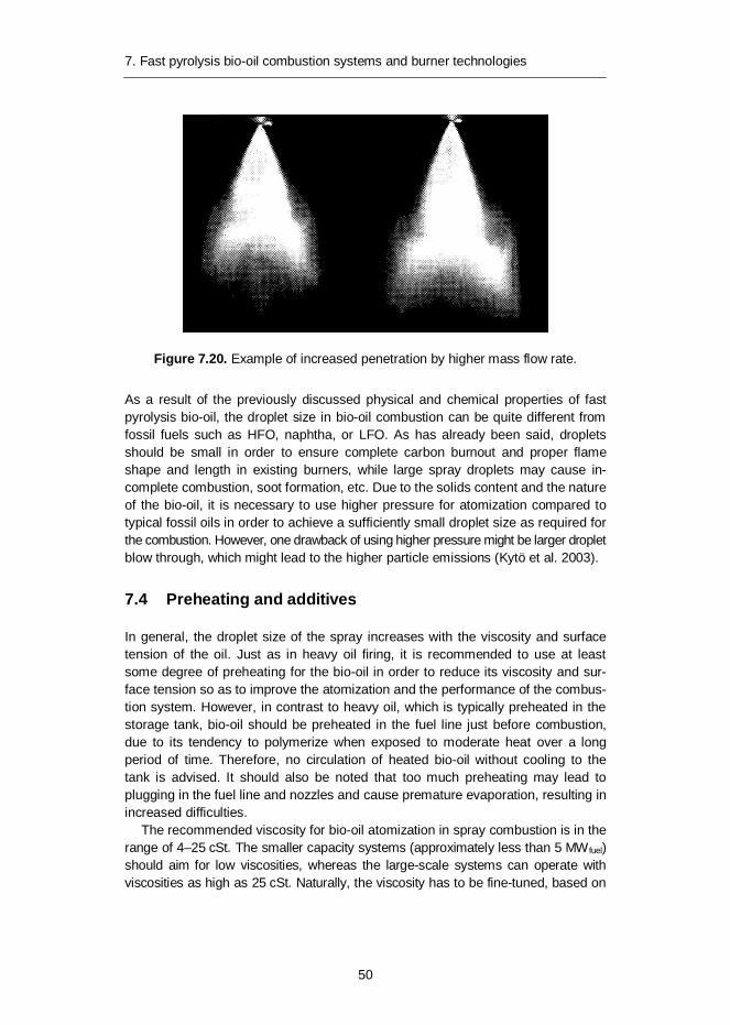
7. Fast pyrolysis bio-oil combustion systems and burner technologies
50
Figure 7.20. Example of increased penetration by higher mass flow rate.
As a result of the previously discussed physical and chemical properties of fast pyrolysis bio-oil, the droplet size in bio-oil combustion can be quite different from fossil fuels such as HFO, naphtha, or LFO. As has already been said, droplets should be small in order to ensure complete carbon burnout and proper flame shape and length in existing burners, while large spray droplets may cause in-complete combustion, soot formation, etc. Due to the solids content and the nature of the bio-oil, it is necessary to use higher pressure for atomization compared to typical fossil oils in order to achieve a sufficiently small droplet size as required for the combustion. However, one drawback of using higher pressure might be larger droplet blow through, which might lead to the higher particle emissions (Kytö et al. 2003).
7.4 Preheating and additives
In general, the droplet size of the spray increases with the viscosity and surface tension of the oil. Just as in heavy oil firing, it is recommended to use at least some degree of preheating for the bio-oil in order to reduce its viscosity and sur-face tension so as to improve the atomization and the performance of the combus-tion system. However, in contrast to heavy oil, which is typically preheated in the storage tank, bio-oil should be preheated in the fuel line just before combustion, due to its tendency to polymerize when exposed to moderate heat over a long period of time. Therefore, no circulation of heated bio-oil without cooling to the tank is advised. It should also be noted that too much preheating may lead to plugging in the fuel line and nozzles and cause premature evaporation, resulting in increased difficulties.
The recommended viscosity for bio-oil atomization in spray combustion is in the range of 4–25 cSt. The smaller capacity systems (approximately less than 5 MW fuel) should aim for low viscosities, whereas the large-scale systems can operate with viscosities as high as 25 cSt. Naturally, the viscosity has to be fine-tuned, based on

7. Fast pyrolysis bio-oil combustion systems and burner technologies
51
the burner and atomizer manufacturer’s instructions. The viscosity of the bio-oil decreases rapidly with temperature (Figure 7.21). Thus, depending on the bio-oil properties it would be favourable to preheat bio-oil to around 40–80 °C just prior to combustion in order to improve the atomization properties of the oil. The fuel de-livery system itself should be constructed from corrosion-resistant materials in order to tackle the low pH of the bio-oil (Krumdieck & Daily 1998, Shaddix & Hardesty 1999, Kirk et al. 2001, Oasmaa et al. 2005).
Figure 7.21. Temperature effect on viscosity of bio-oil.
Preheating primary and atomizing airs is also recommended in order to improve combustion quality. The increase in the temperature of atomizing air reduces its density, which leads to higher relative velocities between air and oil in the nozzle. Preheating of combustion air also increases the flame and flue gas temperatures, as well as promoting the evaporation of the spray droplets, leading to more thorough burnout of the fuel and reduced THC and CO emissions (Tzanetakis et al. 2010). In addition, in diesel engine applications it has been found that bio-oils could not be ignited without proper primary air preheating (Shihadeh & Hochgreb 2000).
Another way to improve the combustibility of bio-oil in spray combustion is to blend it with lighter fuels such as ethanol and methanol. Blending with a lighter fuel decreases the surface tension and density of the bio-oil and increases the overall volatility, heating value and air/fuel ratio in combustion. Alcohols, such as metha-nol and ethanol, are miscible in bio-oil. However, in most cases the addition of lighter fuels to the bio-oil is not the most lucrative solution.
The addition of methanol to bio-oil has been found to accelerate the timing of microexplosions, but it did not increase their effectiveness. On the other hand, addition of water to bio-oil delayed the onset of microexplosion, but enhanced its
1
10
100
1000
10000
0 20 40 60 80 100
Visc
osity
, mPa
s
Temperature, °C
HFO180
LFO heating
PO (water 24wt%)

7. Fast pyrolysis bio-oil combustion systems and burner technologies
52
effectiveness (Shaddix & Tennison 1998). Adding alcohol and/or water to bio-oil also improves its stability.
In conclusion, a combination of moderate preheating of fuel and airs, and if still needed, a minor amount of additive is recommended in order to reduce the viscosity of the bio-oil to the level needed for the combustion application in hand.
7.5 Ignition
Ignition of bio-oil is more difficult than that of hydrocarbon fuel, but once ignited it can be burned steadily. Ignition difficulties related to bio-oils are mainly due to the very high heat of evaporation of water which means that more energy is needed to ignite bio-oils than hydrocarbon fuels. Therefore, the most important issue regard-ing the ignition of bio-oil is to provide enough heat to the area immediate next to the flame holder. Bio-oils can be ignited with the help of pilot flames, or after the addition of ignition improvers, or with the preheating of combustion chambers or combustion air (Lu et al. 2009).
A gas-electric igniter (Figure 7.22) is recommended to be used with bio-oil. The gas-electric igniter is the most suitable and reliable way to ignite the main flame of a bio-oil burner. If the capacity of the main burner is higher than 10 MW, it is practically the only sensible way. A typical gas-electric igniter has a capacity of 45–120 kW and is proved to ignite the main flame of bio-oil with propane or natural gas fuel.
Figure 7.22. High quality gas-electric igniter can also be used as pilot burner if needed.
A gas-electric igniter creates a continuous flame which is easy to aim towards the cloud of atomized bio-oil droplets. This flame provides the capacity needed for the ignition of bio-oil. Such igniters are not prone to the impurities and in “emergency” cases they can also be used as pilot flames for short periods of time.

7. Fast pyrolysis bio-oil combustion systems and burner technologies
53
7.6 Combustion
The evaporation and combustion rates of a bio-oil droplet are slower than the same rates of a mineral oil droplet, mainly because of its high mass density and the significant latent heat of vaporization of water included in the oil.
In general, bio-oils must be fired at higher flow rates than mineral oils due to their low heating value. Nevertheless, this difference is mostly offset by the low air/fuel ratio needed, due to the high oxygen content of the bio-oils. The stoichio-metric mass air/fuel ratio for bio-oil is about 5–7, which is roughly a half that of mineral oils. This same effect accounts for the similarities in adiabatic flame tem-peratures between bio-oil and mineral oil flames (Shaddix & Hardesty 1999).
However, in the bio-oil firing in fire-tube boilers the heat release rate per volume (kW/m3) of the furnace should not be as high as in mineral oil combustion (in which it is normally in the range of 800…1 000 kW/m3) due to the slower droplet burning times and because the bio-oil flame of equivalent power is physically larger. Hence, the power output of existing mineral oil boilers diminishes when bio-oil is used. Bio-oil flames are also very luminous, suggesting the presence of sig-nificant amounts of radiating particles.
If existing burners are used, it is very likely that those should be at least slightly modified, since those burners are optimized to operate with higher heating value fuels such as heavy and light oils, which have completely different characteristics than bio-oil, as discussed above. For example, all the parts in contact with bio-oil should be replaced with parts made of stainless steel or better, and the suitability of the all gaskets and instruments needs to be checked.
One of the key issues in good design for a bio-oil combustion system is to have good atomization and thorough mixing of fuel and air in the system. The atomiza-tion viscosity of the bio-oil should be adjusted suitably via preheating and/or add-ing alcohol so that the size and size distribution of oil droplets are correct and their penetration into the air pattern of the burner is optimal. In earlier bio-oil combus-tion tests, pressure atomization has been found to be more problematic than auxil-iary medium atomization. This is mainly due to problems encountered in pressuriz-ing bio-oil due to its low pH and high solids content, leading to blocking and ero-sion. In this context, it should also be noted that bio-oil possesses only some lubri-cation properties (Oasmaa et al. 2001a).
The high water content of the bio-oil makes the heat production to the adjacent area next to the flame holder harder and expands the physical size of the flame, making flame stabilization harder. Flame blow off should be avoided. Flame stabi-lization can be achieved by utilizing a flame holder or by swirl. However, swirl stabilization has been found to be problematic in some earlier bio-oil combustion test cases. In the future, bio-oil grades used for spray combustion should be standardized, so that a suitable flame stabilization technique can be selected on that basis. Some of the negative properties of the high water content can be com-pensated with the refractory lining put into the front chamber of the boiler.

7. Fast pyrolysis bio-oil combustion systems and burner technologies
54
In the design, it is also necessary to allow higher residence times for bio-oil droplets compared to the mineral oils that distil completely to ensure complete combustion. What is more, different temperature and oxygen distributions inside the combustor are to be expected. The combustor should be designed so that the bio-oil flame does not touch its surfaces at any stage to prevent coking and im-pinging to furnace wall, which can ultimately lead to erosion and emission prob-lems (Krumdieck & Daily 1998, Shaddix & Hardesty 1999, Oasmaa et al. 2001a, Garcìa-Pèrez et al. 2006b, Tzanetakis et al. 2010). The bio-oil flame size with same thermal capacity is typically larger than a fossil oil flame due to the chemical properties of bio-oil. Due to the low pH of the bio-oil no carbon steel can be used in pumps, fuel lines or in burner.
A support fuel or pilot flame may be needed at cold start up or in cases when bio-oil is of poor quality in order to maintain stable combustion. A gas-electric igniter is recommended to be used.
After the burner shut-down, bio-oil must be rinsed from the nozzles in order to avoid clogging (Oasmaa et al. 2001a, Kytö et al. 2003).
With intelligent engineering within these specific constraints, it is possible to design an industrial size combustion system that achieves thorough fuel burnout, good combustion quality and operates reliably with bio-oil (Krumdieck & Daily 1998, Oasmaa et al. 2001a, Tzanetakis 2011).
7.7 Emissions
In general, the emissions in the bio-oil combustion are between those of light oil and the lightest heavy oil, but particulate emissions might be higher and there is practically no SOx-emission (Oasmaa et al. 2001a). Naturally, the emissions from pyrolysis oil combustion are very dependent on the original levels of solids, met-als, water and nitrogen in the oil being combusted.
The NOx-emission is mainly due to the conversion of fuel-bound nitrogen, as the lower flame temperature of pyrolysis oil combustion reduces the production of thermal-NOx. However, total-NOx is a combination of those oxides produced by thermal and fuel bound nitrogen mechanisms (Shaddix & Hardesty 1999, Kytö et al. 2003, Tzanetakis et al. 2010). In order to reduce the NOx-emissions without refining the fuel, the use of staged combustion is one alternative and may be rec-ommended. Other means can also be used, but so far successful references of those are few for bio-oils.
Typical curves for NOx-emissions of fast pyrolysis bio-oil combustion for air-assisted atomization burners are shown in Figure 7.23 with two conversion rates. Most of the combustion set-ups done in firetube boilers are between the presented curves.
High conversion is probable when: target is to minimize CO and unburnt parti-cle emissions, set-up uses high excess air, steam boiler is selected, furnace load is maximized and oil has low water content / high LHV.

7. Fast pyrolysis bio-oil combustion systems and burner technologies
55
Low conversion is probable when: target is to minimize NOx and unburnt parti-cle emissions are not in main focus, set-up uses low excess air, hot water boiler is selected, furnace load is minimized and oil has high water content / low LHV
Figure 7.23. Typical curves for air-assisted atomization burners with two conver-sion rates. N-content is in wt% and as received condition (Metso Power).
NOx-measurements were completed for two pyrolysis oils produced by the same process but differing in fuel nitrogen content. The combustion data indicated that (1) fuel nitrogen conversion efficiency increases with increasing oxygen concentra-tion if flame temperature is held constant, (2) fuel nitrogen conversion efficiencies decrease with increasing fuel nitrogen content (NO levels increase, but conversion efficiencies decrease), and (3) NOx-emissions are dominated by NO, which is primarily formed from fuel nitrogen (Baxter et al. 1995).
Depending on the design of the burner and combustion system and the bio-oil quality, the carbon monoxide emissions may be somewhat higher than those of mineral oils, but in general they should be within acceptable limits (Shaddix & Hardesty 1999).
Solid particle emissions from bio-oil combustion tests indicate relatively big dif-ference from case by case. That is mainly due to several kinds of oils used. Par-ticulate emissions might be high depending on the original levels of incombustible solids in the bio-oil. In order to prevent fouling of heat transfer surfaces in the boiler and to reduce erosion in the nozzles, valves and pumps and to reduce the particulate emissions, it is recommended to reduce the solids content of the bio-oil to < 0.1 wt% if possible and to ensure that inorganics in the form of ash and sand left over from the feedstock are present at as low concentrations as possible (Oasmaa et al. 2005). Also combustion set-up and burner types and adjustments are very different. Furthermore, more difficult atomization of the bio-oil might lead

7. Fast pyrolysis bio-oil combustion systems and burner technologies
56
to incomplete particle burnout. However, under good operating conditions, the particulates are mainly ash. Target is typically to optimize flame into the furnace and avoid operational problems. When system is optimized levels like 100 mg/m3n (3% O2) can be possible with medium quality bio-oil. On the other hand levels like 300 mg/m3n (3% O2) can be measured if conditions are different. The particles are typically very small in size (< 10 µm) and the amount of unburnt in solids is low (see also Figure 7.13). The consortium of Metso-Fortum-UPM-VTT carries out also a study how to optimize the most sensible and cost-effective particle emission reduction technology and filters for small and medium size of boilers.
The soot number measured by the Bacharac method for bio-oil is different from the ones measured for mineral oils. This is because the colouring browning agents are already present in the bio-oil. Thus, brown colour is typically obtained with bio-oils. Therefore, another method than Bacharac should be used with bio-oils as the darkness of the sample does not give indication of sooting.
There is not much published data on VOC’s, PAH’s or other analysis of the flue gas. Fortum Wärme combusted pyrolysis oil (solids 0.04 wt%, water 22 wt%, vis-cosity 24 cSt at 40 °C) in a modified boiler (Arimax Eetta 500 kW) with a modified burner (Oilon KP 38 H). Flue gas samples were analysed with different gas ana-lysers. Analysers were calibrated with calibration gas. Isokinetic dust sampling was performed by withdrawing flue gas through a quartz fibre filter. Filter was dried before and after the sample. Typical combustion tests are shown in the Ta-ble 7.2 during combustion various gases were monitored on-line continuously. Due to the very low levels of carbon monoxide, a second measuring device was used, which confirmed this result. Since both the carbon monoxide and the hydro-carbon emissions are simultaneously very low, it is apparent that there is very clean combustion. Both tar and PAH (poly aromatic hydrocarbons) have been measured from various pyrolysis oils during the development of the combustion system with Oilon. Tar compounds were measured by Swedish SP-1686 method and PAH in a modified method. Values for tar have been decreased from about 3 mg/MJ to under the detection limit of the system while PAHs from 1 000 mi-crogram/MJ to under 12 (Gust 2004).
Table 7.2. Exhaust gas measurements.
Time O2 %
CO ppm
NOx ppm
CxHy ppm
09:30 4,7 15 103 0 09:40 4,7 10 100 0 10:10 4,4 9 101 1 10:20 4,4 7 100 1 10:30 4,3 6 102 0 10:40 4,3 6 102 0 10:50 4,3 6 103 0 Average 4,4 8,4 101,6 ~0

8. Use of fast pyrolysis bio-oils for heat or CHP
57
8. Use of fast pyrolysis bio-oils for heat or CHP
8.1 Bio-oil co-firing
Bio-oil may be co-fired in natural gas-fired power plants. The advantages gained by co-firing biomass in fossil fuel power plants are well-known and include high overall plant efficiencies, and reduced investment costs compared to 100% bio-mass plants, and already existing industrial sites (advantages in terms of authori-zations and permissions). These plants are also typically not equipped with dust collection devices, and hence an ash-free fuel, such as bio-oil, is of special inter-est to these producers.
Bio-oil has been co-fired in a 350 MWe natural gas fired power station in Harculo, the Netherlands, by BTG, where 15 tons of bio-oil (> 1% bio-oil of the feed) was co-fired with minimal retrofitting and high system reliability. Bio-oil was converted into 25 MWh of electricity (Venderbosch et al. 2002, Wagenar et al. 2004). Wagenar et al. (2002) have also reported bio-oil co-firing in a coal-fired power plant.
Bio-oil produced by Red Arrow Products Company by the RTPTM process was co-fired in a coal station at the Manitowoc public utilities power station, Wisconsin, in a 20 MWe low-sulphur Kentucky coal-fired stocker boiler. A total of 370 h of operation have been accumulated, feeding 5% of thermal input by pyrolysis oil, corresponding to 1 MWe power output. The plant was operated without significant problems after cost-effective modification of the boiler to allow for co-firing. No adverse effects were observed on emission levels (sulphur emissions were re-duced by 5%), maintenance programs or ash handling (Sturzl 1997).
Industrial ovens are also potential users of bio-oil. At least short duration lime kiln tests have been carried out, although results have not been published. Canmet has studied the use of pyrolysis oils in drying kilns. Pyrolysis oils per-formed well in a hot furnace (approx. 500 °C). At ambient temperatures start-up with 50% natural gas was necessary in order to sustain ignition. Addition of 10–20% natural gas improved emissions and stabilized the flame. A CLM nozzle with external mix air assist atomiser worked well, but improved nozzles to achieve a “cold” start are required (Preto et al. 2012).

8. Use of fast pyrolysis bio-oils for heat or CHP
58
Recently two burner manufactures, Stork Technical Services (Netherlands) and Dreizler GmbH (Germany), carried out a test programme to research the operating window and performance of a standard oil-gas burner firing bio-oil (Rinket & Tous-saint 2012). Using a standard burner design makes it possible to directly imple-ment the burners at the customer’s site.
The tests performed by Dreizler were done with a standard Marathon gas-oil burner on a test fire tube. Tests were carried out at various loads and bio-oil co-firing rates. The maximum firing rate was 600 kWth, with a maximum achievable oil co-firing rate of 65%.
It was found that the burner co-firing bio-oil could be operated fully automatically and in a stable way. The emissions of dust and NOx were found to meet the limits in the Netherlands for combustion systems using biomass with a heat capacity smaller than 1 MWth. The tested burner (type) can be delivered in a range of 300 kWth up to 10 MWth.
The tests by Stork were conducted on the test boiler in Hengelo, a 9 MWth wa-ter tube boiler. A standard Stork Low NOx Double Register gas and oil burner was used for the tests. The bio-oil was preheated to a temperature of 60˚C to enhance the atomization, and an optimized Y-jet steam-assisted atomizer was used.
Successful tests were carried out at a burner capacity of 2.6 MW th, with a bio-oil co-firing rate of nearly 80%. The flame of the bio-oil stabilized at a greater distance from the impeller than the HFO flame. Also, a small natural gas pilot flame of 0.6 MW was required for flame stabilization while combusting bio-oil. However, it is believed that this pilot flame can be reduced or even omitted when preheating the combustion air (Rinket & Toussaint 2012).
Dust (13–20 mg/Nm3@3%O2) and NOx (133 mg/Nm3@3%O2) emissions of used pine bio-oils were found to meet the Dutch emission limits for combustion systems firing (liquid) biomass up to a heat input of 5 MWth. Additionally, these tests have generated valuable information on the handling and combustion of wood-based bio-oil for heat generation. As a result, both suppliers are able to offer burner systems with performance guarantees.
8.2 Commercial combustion of bio-oil at Red Arrow, USA
The only commercial system that has been operating for over 10 years, in which bio-oil is used for heat generation, is located at the Red Arrow Products pyrolysis plant in the United States. A 5 MWth swirl burner is used for combustion of the pyrolysis bio-oil fractions and char and gas from the plant, with average emissions of 17% CO, 1.2% NOx, and 0.2% formaldehyde of the permitted levels (Sturzl 1997).
8.3 Bio-oil combustion for district heat in Stockholm, Sweden
The first encouraging large-scale bio-oil utilization tests with published results (Hallgren 1996, Hägerstedt & Jakobssen 1999) were carried out at Årsta District Heating Plant in Sweden. Årsta District Heating Plant is one of several production

8. Use of fast pyrolysis bio-oils for heat or CHP
59
plants in the south district heating net of Stockholm. The plant is used as a peak load and stand-by plant within the net. Årsta District Heating Plant is equipped with four hot water boilers and one boiler producing steam for soot blowers. The plant is operating from October until the middle of May. The 9 MW boiler was originally designed for heavy fossil fuel, but it has later adapted to different bio-oils. The boiler has forced circulation with a temperature regulated at 160 °C and no flue gas cleaning equipment. The burner is a rotating cup burner manufactured by Petrokraft AB. Fuel is added inside a rotating cone (5 000 rpm), and the rotation together with the primary air added outside the cone, atomises the fuel. When using different fuels, it helps to mix them.
Several different fast pyrolysis bio-oils (10–15 m3) were subsequently tested. Fuels were produced in the Fortum’s pilot-scale production plant in Porvoo, Fin-land, during the autumn of 2003, shipped to Stockholm in September 2003 and stored for 8 months in 1m3 plastic containers.
Before testing, fuel was pumped from the containers into a storage tank. There was no sediment layer and viscosity was good at room temperature. The liquid was pumped easily, but a problem was the characteristic smell. Having a low heating value it was necessary to co-fire the pyrolysis oil with a support fuel. In this test, fatty acid was used, but it could also have been tall pitch oil or heavy oil (heat-ing value 45 MJ/kg). The experiments indicated that pyrolysis oil can be burnt, but further practical information is required about storage, handling and combustion.
Support fuel was delivered to the mass flow meter and then filtered and pre-heated in the normal fuel system. Pyrolysis oil was handled in a separate test unit – an airtight, stainless, 10 m3 tank with a stirring device. The bio-oil was led from the tank to a loop-rotor pump with controlled rpm and on to a 400 micrometer filter, a pre-heater and through a mass flow meter.
The boiler was started up with 100% support fuel. After a while, fast pyrolysis bio-oil was added. During the test, burning bio-oil was mixed with a decreasing amount of fatty acid. When the combustion began to be unstable, the flame started to pulsate and the CO-level to increase. The amount of PO was then reduced until stable conditions appeared again. The emissions measurement was started up (Solantausta 2004).
It was noticed that the combustion was stabilized from a higher O2 level. Over the two days, the boiler was operating with bio-oil for approximately six hours, and the total consumption of PO was about 4 m3. The result of the measurements in the flue gas are shown in Table 8.1.

8. Use of fast pyrolysis bio-oils for heat or CHP
60
Table 8.1. Bio-oil combustion emissions (Solantausta 2004).
Parameter Unit Average O2 content vol % dg 4,5 CO2 content calculated vol % dg 12,7 CO content ppm dg 13 Dust content mg/m3ndg 158 Spec dust emission mg/MJ 68 NOx content ppm 71 NOx mg/m3ndg 145 NOx emission mg/MJ 62 SO2 content ppm < 2 Spec. gas flow* m3ndg/MJ fuel 0,43 * Theoretically from oil analysis and measured O2 content. dg = dry gas
It was observed that handling bio-oil was easy and the test worked out well; emissions measurements indicated dust content higher than expected, while the NOx-level was more or less the same as with pure fatty acid, and further tests are needed.
8.4 Combustion tests in an industrial boiler at Oilon, Finland
In the late 1990s, VTT carried out (Oasmaa et al. 2001a) combustion tests at Oilon in an industrial boiler having a 4 MW nominal heat output with one pyrolysis oil. First, the combustion conditions were tested and optimised. Next, various pyrolysis oils were combusted at the same conditions for comparison. Finally, a batch of poor-quality, high-water content oil was combusted. It was concluded that proper handling and pumping of bio-oils is essential. Extra cooling air for the noz-zle could be useful for combustion and to keep them clean and in good condition. With all oils, the flame was larger and combustion took longer than with mineral oils. Clear differences were reported in combustibility and emissions using various pyrolysis oils. High solids content, very high (> 30 wt%) water content, and inho-mogeneity caused higher particulate emissions. Quality specifications should include at least water and solids content, and viscosity.
8.5 Fortum’s field tests to replace light fuel oil using a modified burner
In 2003, Fortum (formerly Neste Oil) successfully performed field tests with their pyrolysis product Forestera in a 400 kWth heating fuel boiler. Their aim was to replace light fuel oil in heating. Field tests were performed in order to verify critical components and to determine the required fuel quality.
The burner was provided by Oilon Oy of Finland, which was the result of their joint development work during the period 2000–2002 (Martin & Gust 2003, Kytö et

8. Use of fast pyrolysis bio-oils for heat or CHP
61
al. 2003). Existing light fuel oil burner equipment has been optimized with a much higher heating value fuel than pyrolysis liquid. To achieve an adequate fuel/air mixtures and velocities, much less air was required for combustion, which caused the flame to expand and extend to the end of the combustion chamber. Internal heating was not adequate to combust particulates and high molecular tars, which increased emissions. This required a new burner retention head to be developed. Because of the high viscosity of pyrolysis oil compared to light fuel oil, a higher pressure for atomisation was necessary in order to achieve the small drop size required for efficient combustion. One drawback of this was large droplet blow through, which is caused by a small fraction of the drops being larger than the average size and leaving the flame centre before they were combusted. This led to high emissions. The low pH meant that normal carbon steels could not be used in pumps and fuel lines. Stainless steel pumps are considerably more expensive than normal fuel pumps. Since pyrolysis liquids contain significant amounts of water and have a low heating value, they are difficult to ignite. This has meant that the combustion chamber must first be warmed up to ignition temperatures by a separate fuel. This temperature was found to depend on the type of burner head solution adopted. In practise, this is possible in less than 30 seconds. Finally, it was found that after burner shut-down, pyrolysis liquids must be rinsed out of nozzles in order to prevent clogging (Kytö et al. 2003).
In the field tests more than 12m3 of Forestera bio-oil was combusted, in over 1 500 cycles. The combustion system was fully automated and operated under the control of a thermostat. One of the more important findings of the work was the necessity to reduce solids to < 0.1 wt%, and to ensure that inorganics in the form of ash and sand left over from the feedstock are present in concentrations of < 0.03 wt%. The conclusion of these tests was that emissions could be reduced to acceptable levels, provided that a fuel of sufficient quality is used, and that flame characteristics are modified using a modified burner. It was also found that the combustion system is more complex and costly than for conventional heating fuels. This would require a lower-cost pyrolysis bio-oil to compensate for the high-er installation costs to get customers to be willing to test this option.
8.6 Replacing heavy fuel oil at Fortum’s district heating plant
Significant amounts of bio-oil have been combusted in Fortum Power and Heat’s 1.5 MW district heating plant in Masala (Figure 8.1), Finland since 2010. The bio-oil was produced at Metso’s pilot plant, and it was whole oil including extractive-rich top phase. No additives were used. The existing burner was replaced with a new bio-oil burner consisting of a modified mono block heavy fuel oil burner origi-nally designed for high-pressure atomization. The modifications to the existing burner included, for example, burner head configuration. Also the piping, pumping and valve systems including pre-heating of the oil were specially designed for bio-oil.
The total amount of bio-oil combusted is currently above 40 tons. Two main topics for the tests were the overall functionality of the bio-oil receiving, storing,

8. Use of fast pyrolysis bio-oils for heat or CHP
62
and pumping system and the function of the burner. Both topics were successfully addressed. The receiving system and oil tank were located outside the boiler building. The system worked well, despite the outside temperatures, which varied from -20 to +10 °C during the test periods. As a result, good reliability and a satis-factory turn-down ratio of 1:3 were achieved. The unit has even been operated unmanned for 1 night. Flue gas emissions were close to those of heavy fuel oil. No odour emissions occurred (Solantausta et al. 2012).
Figure 8.1. Fortum’s district heating plant in Masala firing bio-oil in 2010.
Table 8.2 below shows data on emissions from pyrolysis oil boiler combustion from various sources.
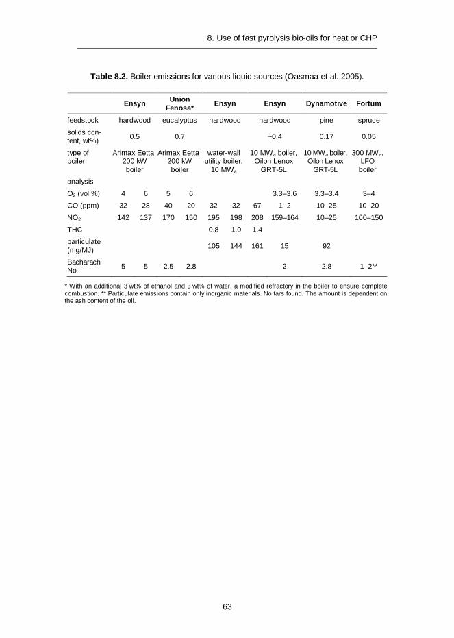
8. Use of fast pyrolysis bio-oils for heat or CHP
63
Table 8.2. Boiler emissions for various liquid sources (Oasmaa et al. 2005).
Ensyn Union Fenosa* Ensyn Ensyn Dynamotive Fortum
feedstock hardwood eucalyptus hardwood hardwood pine spruce
solids con-tent, wt%) 0.5 0.7 ~0.4 0.17 0.05
type of boiler
Arimax Eetta 200 kW boiler
Arimax Eetta 200 kW boiler
water-wall utility boiler,
10 MWa
10 MWa boiler, Oilon Lenox
GRT-5L
10 MWa boiler, Oilon Lenox
GRT-5L
300 MWa, LFO boiler
analysis
O2 (vol %) 4 6 5 6 3.3–3.6 3.3–3.4 3–4
CO (ppm) 32 28 40 20 32 32 67 1–2 10–25 10–20
NO2 142 137 170 150 195 198 208 159–164 10–25 100–150
THC 0.8 1.0 1.4
particulate (mg/MJ) 105 144 161 15 92
Bacharach No. 5 5 2.5 2.8 2 2.8 1–2**
* With an additional 3 wt% of ethanol and 3 wt% of water, a modified refractory in the boiler to ensure complete combustion. ** Particulate emissions contain only inorganic materials. No tars found. The amount is dependent on the ash content of the oil.

9. Health, safety, handling and transport
64
9. Health, safety, handling and transport
REACH registration project of bio-oil is on-going under lead of Fortum Power and Heat. Registration of fast pyrolysis bio-oil to ECHA will be carried out by the end of May 2013. Data for REACH registration has so far been mainly provided by VTT and IEA Bioenergy Task 34. For example, original toxicological and ecotoxicological data created in EU Biotox project has been assigned to Fortum.
9.1 Material and Safety Data Sheets (MSDS)
During testing and utilisation of bio-oils, the oil must be handled, stored, trans-ferred and sampled. MSDSs are essential for the safe use, handling, storage and transportation of bio-oils. There are various MSDSs in use by various companies. The IEA Bioenergy Task 34 on Pyrolysis will prepare a new MSDS for fast pyrolysis bio-oils based on newly processed data (see: http://www.pyne.co.uk/?_id=116).
9.2 Handling
Fast pyrolysis bio-oils contain high amount of energy in solid phase components and therefore filtering them away is not the primary target. However, the fuel handling chain has to be designed so that it will not suffer (block, fill up) because of solid particle material. Also pumping and atomizing processes require suitable filtration.
It was reported in Fortum’s field trials that any inclusion of sand or any other hard solid (> 0.05 wt%) in the bio-oil would cause erosion in the pump and in the nozzles (Figure 9.1). Nozzles had to be replaced every 1 000 litres of fuel com-busted. Emissions were also affected with higher particulates found in the flue gas. The erosion is due to the high pressure, 17–20 bar, required to obtain small drop size and clean combustion (Gust 2004).

9. Health, safety, handling and transport
65
Figure 9.1. Erosion striations in nozzle.
Some grades of bio-oils must be heated up for proper atomization but still over-heating has to be avoided. Due to the instability of bio-oils, special care has to be taken in using these liquids. Heating should be carried out indirectly with a low-temperature surface (e.g. warm water heat exchanger, jacketed tanks). Direct heating can cause coking of the bio-oil due to overheating (Figure 9.2). Temperatures between 40–80 °C are recommended for pumping in order to keep the viscosity low and reduce the rate of decomposition. Prolonged recycling of liquids with thermal cycling leads to a significant deterioration in quality and increase in viscosity.

9. Health, safety, handling and transport
66
Figure 9.2. Coking in the supply line due to overheating of bio-oil (Preto et al. 2012).
9.3 Guidelines for transportation
As the demand for bio-oils increases, it is important that they are transported in a safe and environmentally secure manner. The appropriate national and interna-tional regulations need to be met during transport and may need to apply to more than one mode of transport.
Even though valid for several biomass-derived liquids and other fuels, the method for flash point is not suitable for bio-oils because they contain a high amount of water evaporating significantly below 100 °C and extinguishing the possible flame caused by volatiles with a low flash point. Therefore, another test method is needed in order to measure flammability appropriately for bio-oils. In some cases, the producer may be able to justify a case where the liquids are not subject to dangerous goods requirements for shipment. Various bio-oils were tested by the method, and it was proved that they are incapable of sustained com-bustion and can be classified as non-flammable liquids.
The EU-funded BIOTOX project (BIOTOX 2005) has provided data on the tox-icity of biomass-derived bio-oils. The data combined both fast and slow pyrolysis oils. In IEA Bioenergy Task 34, this data was forwarded to toxicity experts and con-clusions relevant for fast pyrolysis oils were drawn. The available data indicates that acute oral toxicity from a single dose is high (> 2 500 mg/kg) which puts it in the “slightly toxic” category. The most severe adverse effect was the irritation/corrosion changes observed when it was applied dermally to a rabbit. Because of the severi-ty of the dermal changes (erythema/oedema i.e. burns) and for ethical reasons, the eye irritation test was not run. These effects are probably due to phenols, aldehydes and/or ketones shown to be present in the test material. Thus, skin and eye protection will be necessary for plant workers. The mutagenic activity gave a slight positive response in the bacterial forward mutation assay, a modest re-

9. Health, safety, handling and transport
67
sponse in the mouse lymphoma cell culture assay in the absence of metabolic activation, but was negative in the mouse bone marrow micronucleus test. Based on these results, it is recommended that a life span skin painting assay be con-ducted to determine whether the test material is carcinogenic. This is especially important since the test material contains measureable amounts of PAHs including benzo(a)pyrene and benzo(a)anthracene, both known carcinogens. Additionally, around one half (46 wt%) of the test material has not been characterized with respect to chemical composition. These are important considerations since skin contact is a likely route of exposure for plant workers. It will also be important to consider additional toxicological testing as the technology progresses toward commercialization. This should include likely routes of exposure (probably dermal and inhalation) and endpoints such as neurotoxicity, reproductive effects, and teratogenicity.
At the moment, it seems that bio-oil should be classified as Class 8 (Corrosive) product. However, more testing is needed. In order to make a final classification, all required tests should be carried out according to relevant transport regulations, referring to the UN (United Nations) Manual of Tests and Criteria, OECD (The Organisation for Economic Co-operation and Development test), and others as applicable. It also appears that the variations between different products could lead to different classifications. It is the duty of each bio-oil producer to prove that the classification suggested in this paper is also valid for their product.
For bio-oils there is no UN number assigned at the moment. If further testing shows that the properties for bio-oils are mostly the same, it may be possible to suggest a new UN number for the product. This suggestion should be made to the UN, normally by a competent authority, or an association.
Suggestion for transport classification (material safety data sheet, Section 14 Transport Information): UN NUMBER:3265, PROPER SHIPPING NAME: CORROSIVE LIQUID, ACIDIC, ORGANIC, NOS (contains x, y *), CLASS: 8, PACKING GROUP: III, ENVIRONMENTAL HAZARDS NO (*) (Table 9.1). It is the oil producer’s responsi-bility to show that their bio-oil meets same classification as shown here. More research is needed on material testing using a standard or well-proven methods at relevant test conditions are needed (Oasmaa et al. 2012b).
(*) = relevant chemical/technical names which have affected to the classification (e.g., acetic acid)

9. Health, safety, handling and transport
68
Table 9.1. Summary table of transportation guidelines.


10. Conclusions
69
10. Conclusions
Biomass fast pyrolysis bio-oils are completely different from petroleum fuels as regards both their physical properties and chemical composition. When the unu-sual properties of these bio-oils are carefully taken into account, their combustion without a pilot flame or support fuel is possible on an industrial scale. Even blending these oils with alcohols in order to improve combustion is not necessarily required. However, preheating of combustion airs and mild preheating of bio-oil in the fuel line just prior to combustion are recommended.
In the recent industrial scale bio-oil combustion tests, bio-oil has been found to be technically suitable for replacing heavy fuel oil in district heating applications. This kind of replacement, however, needs some modifications to be made to the existing units, which need to be engineered carefully. For example, all the parts in contact with bio-oil should be replaced with parts made of stainless steel or better, and the suitability of all gaskets and instruments needs to be checked.
In general, the emissions in the bio-oil combustion are very dependent on the original levels of solids, water and nitrogen in the oil being combusted. Typically, the emissions levels are between those of light oil and the lightest heavy oil, but particulate emission may be higher. On the other hand, there are practically no SOx-emissions generated in the bio-oil combustion. The Bacharac method is not suitable for indicating soot formation in bio-oil combustion.
The NOx-emission in bio-oil combustion mainly originates from fuel-bound ni-trogen. Staged combustion for NOx-reduction may be recommended, as successful air staging in natural gas, heavy and light fuel oil combustion has already been done.
The recent bio-oil combustion tests have also shown that bio-oil combustion technology works well, and there are not many possibilities of further lowering particulate emissions, since the majority of the particulates are typically incombus-tible matter. Therefore, it is recommended to reduce the solids content of the bio-oil to < 0.1 wt% if possible, and to ensure that inorganics in the form of ash and sand are present at as low a concentration as possible.
Current burner designs are quite sensitive to changes in the quality of the bio-oil, which may cause problems in ignition, flame detection and flame stabilization. Therefore, in order to be able to create reliable bio-oil combustion systems that operate at high efficiency, bio-oil grades should be standardized for combustion

10. Conclusions
70
applications. Consequently, international standards, norms, specifications and guidelines should be defined and created urgently.
Careful quality control, combined with standards and specifications, all the way from feedstock harvesting through production to end-use is recommended in order to make sure that emission targets and limits in combustion applications are achieved.
In the earlier bio-oil combustion tests, pressure atomization had been found to be more problematic than auxiliary medium atomization. The problems experi-enced with pressure atomization were due to difficulties in bio-oil pressurizing and erosion and blocking.
Steam and air assisted atomization could be quite a natural choice in locations where it is possible. However, in those cases it should be borne in mind that too heavy preheating of bio-oil in fuel lines usually leads to blocking problems.
To summarise, the authors would like to indicate that there are possibilities for all the burner technologies and models described earlier to be further developed so as to meet the challenges generally caused by the nature, quality and charac-teristics of the bio-oils. So far, relatively few burner manufacturers have developed commercially available burner models for fast pyrolysis bio-oils. Environmental requirements affect the commercialization of the burner technologies and the quality of the oil required for the combustion applications. Naturally, the end-user of the oil is interested in the total costs of the combustion concept compared to those of fossil fuels. Therefore, the cost-effectiveness of the total package is ex-tremely important.
The authors are deeply involved in developing further cost-efficient fast pyroly-sis bio-oil combustion applications in the future.

71
References
Agblevor, F.A., Besler, S. & Evans R.J. 1995. Inorganic Compounds in Biomass Feedstocks: Their Role in Char Formation and Effect on the Quality of Fast Pyrolysis Oils. In: Proceedings, Biomass Pyrolysis Oil Properties and Combustion Meeting, September 26–28, Estes Park, Colorado. Milne, T. A. (Ed.). NREL-CP-430-7215, National Renewable Energy Laboratory, Golden, Colorado. Pp. 77–89.
Agblevor F.A. & Foster, A. 2010. Rapid Method for the Determination of Total Acid Number (TAN) of Biooils. AIChE 2010 Annual meeting, Salt Lake City, USA.
ASTM D 93. 1991. Standard test method for flash point by Pensky-Martens closed tester. Easton, MD: American Society for Testing and Materials.
ASTM D 95. 2010. Standard test method for water in petroleum products and bituminous materials by distillation. Easton, MD: American Society for Testing and Materials.
ASTM D 97. 1993. Standard test method for pour point of petroleum oils. Easton, MD: American Society for Testing and Materials.
ASTM D 445. 1988. Standard test method for kinematic viscosity of transparent and opaque liquids (and the calculation of dynamic viscosity). Easton, MD: American Society for Testing and Materials.
ASTM D 664. Standard test method for acid number of petroleum products by potentiometric titration. Easton, MD: American Society for Testing and Materials.
ASTM D 4052. 1988. Standard test method for density and relative density of liquids by digital density meter. Easton, MD: American Society for Testing and Materials.
ASTM D 4530. Standard test method for determination of carbon residue (Micro Method). Easton, MD: American Society for Testing and Materials.
ASTM D 5291-92. Standard test methods for instrumental determination of car-bon, hydrogen, and nitrogen in petroleum products and lubricants. Easton, MD: American Society for Testing and Materials.
ASTM D 7544. Standard specification for pyrolysis liquid biofuel. Easton, MD: American Society for Testing and Materials.

72
ASTM D 7579. Standard test method for pyrolysis solids content in pyrolysis liquids by filtration of solids in methanol. Easton, MD: American Society for Testing and Materials.
ASTM E 203. 1996. Standard test method to water using volumetric Karl Fischer Titration. Easton, MD: American Society for Testing and Materials.
Aubin, H. & Roy, C. 1980. Study on the corrosiveness of wood pyrolysis oils. Fuel Science & Technology International, Vol. 8, Issue 1, pp. 77–86.
Baxter, L.L, Jenkins, B.M & Winter, F. 1995. Baseline nox emissions during com-bustion of wood-derived pyrolysis oils. Sandia National Laboratories, Sandia Report SAND94-8780.
BIOTOX 2005. An assessment of bio-oil toxicity for safe handling and transportation. EU-BIOTOX. EU Contract no. NNE5-2001-00744-BIOTOX Part I: Publishable Final Report. September 200. http://ec.europa.eu/energy/renewables/ bioenergy/doc/pyrolysis/biotox_publishable_report.pdf.
Branca, C., Di Blasi, C. & Elefante, R. 2005. Devolatilization and heterogeneous combustion of wood fast pyrolysis oils. Industrial & Engineering Chemical Research, Vol. 44, No. 4, pp. 799–810.
Calabria, R., Chiariello, F. & Massoli, P. 2006. Combustion fundamentals of pyrolysis oil based fuels. Experimental Thermal and Fluid Science, Vol. 31, pp. 413–420.
Chiaramonti, D., Riccio, G., Baglioni, P., Bonini, M., Milani, S., Soldaini, I., Cala-bria, R. & Massoli, P. 2005. Sprays of biomass pyrolysis oil emulsions: modeling and experimental investigation. Preliminary results and modeling. In: Proceeding of the 14th European biomass conference & exhibition, Paris.
D’Alessio, J., Lazzaro, M., Massoli, P. & Moccia, V. 1998. Thermo-optical investigation of burning biomass pyrolysis oil droplets. In: Twenty- Seventh Symposium (International) on Combustion. The Combustion Institute. Pp. 1915–1922.
Diebold, J. 2000. A Review of the Chemical and Physical Mechanisms of the Storage Stability of Fast Pyrolysis Bio-Oils. January 2000. NREL/SR-570-27613.
Diebold, J.P. & Czernik, S. 1997. Additives to lower and stabilize the viscosity of pyrolysis oils during storage. Energy & Fuels, Vol. 11, No. 5, pp. 1081–1091.
Diebold, J.P. & Power, A.J. 1988. Engineering Aspects of the Vortex Pyrolysis Reactor to Produce Primary Pyrolysis Oil Vapors for Use in Resins and

73
Adhesives. Research in Thermochemical Biomass Conversion, Conference Proceedings. Bridgwater, A.V. & Kuester, J.L. (eds.). Pp. 609–628.
Diebold, J.P., Milne, T., Czernik, S., Oasmaa, A., Bridgwater, A.V., Cuevas, A., Gust, S., Huffman, D. & Piskorz, J. 1997. Proposed specifications for various grades of pyrolysis oils. In: Bridgwater, A.V. & Boocock, D.G.B. (Eds.). Developments in Thermochemical Biomass Conversion, Banff, 20–24 May 1996. Glasgow: Blackie Academic & Professional. Vol. 1. Pp. 33–447.
DIN 51900. 1977. Testing of solid and liquid fuels; determination of gross calorific value by the bomb calorimeter and calculation of net calorific value; method with the adiabatic jacket. Berlin: DIN Deutsches Institut für Normung e.V.
DIN EN 7. 1975. Determination of ash from petroleum products. Berlin: DIN Deutsches Institut für Normung e.V.
Dyroff, G.V. 1993. Manual on significance of tests for petroleum products. 6. ed. Phila-delphia: ASTM.
Elliott, D.C., Oasmaa, A., Preto, F., Meier, D. & Bridgwater, A.V. 2012a. Results of the IEA Round Robin on Viscosity and Aging of Fast Pyrolysis Bio-oils. Energy & Fuels, Vol. 26, No. 6, pp. 3769–3776.
Elliott, D.C., Oasmaa, A., Meier, D., Preto, F. & Bridgewater, A.V. 2012b. Results of the IEA Round Robin on Viscosity and Aging of Fast Pyrolysis Bio-oils: Long-Term Tests and Repeatability. Energy & Fuels, Vol. 26, No. 12, pp. 7362–7366.
Freel, B. & Graham, R.G. 1991. Method and apparatus for a circulated bed transport fast pyrolysis reactor system. US Patent WO/1991/011499. 08.08.1991.
García-Pérez, M., Chaala, A., Pakdel, H., Kretschmer, D., Rodrigue, D. & Roy, C. 2006a. Multiphase Structure of Bio-Oils. Energy Fuels, 20, pp. 364–375.
Garcìa-Pèrez, M., Lappas, P., Hugher, P., Dell, L., Chaala, A., Kretscmer, D. & Roy, C. 2006b. Evaporation and combustion characteristics of biomass vacuum pyrolysis oils, IFRF Combustion Journal, Article Number 200601.
Giffen, E. & Muraszew, A. 1953. Atomization of liquid fuels. Chapman and Hall, London.
Gust, S. 1997. Combustion experiences of flash pyrolysis fuel in intermediate size boilers. In: Bridgwater, A.V. & Boocock, D.G.B. Developments in thermo-chemical biomass conversion. Vol. 1. Pp. 481–488.

74
Gust, S. 2004. Contract N°: ENK5-CT-2002-00690, Project N°: NNE5-CT-2001-00604. A New Competitive Liquid Biofuel for Heating, Combio, Date of issue of this report: 25.6.2004.
Hägerstedt, L.-E. & Jakobsson, A. 1999. Bio fuel oil for power plants and boilers. Final report: Handling, storage and transport of bio fuel oil. Stockholm: Birka Teknik och Miljö AB. EC Contract JOR3-CT95-0025.
Hallgren, B. 1996. Test report of Metlab Miljö AB. Skelleftehamn: Metlab Miljö AB. Reg. no. ALL1668, 1996 02 0809. 17 p.
Jamieson, D.T., Irving, J.B. & Tudhope, J.S. 1975. Liquid thermal conductivity: a data survey to 1973. Edinburgh: H.M. Stationery Off.
Kirk, D.W., Li, Z.R., Fuleki, D. & Patnaik, P.C. 2001. Materials compatibility with pyrolysis Biofuel. Paper 2001-GT-0006. Presented at ASME Turbo Expo 2001, New Orleans, Louisiana, June 4–7, 2001.
Krumdieck, S.P, & Daily J.W. 1998. Evaluation the Feasibility of Biomass Pyrolysis Oil for Spray Combustion Applications. Combust. Sci. and Tech., Vol. 134, pp. 351–365.
Kytö, M., Martin, P. & Gust, S. 2003. Development of combustors for pyrolysis liquids. In: Pyrolysis and Gasification of Biomass and Waste, Strasbourg, France, September 30 – October 1, 2002. Bridgwater, A. (Ed.). CPL Press: Newbury, U.K. Pp. 187–190.
Lefebvre, A.H. 1989. Atomization and Sprays, Hemisphere Publishing, New York.
Lehto, J., Jokela, P., Alin, J., Solantausta, Y. & Oasmaa, A. 2010. Bio-oil Production Integrated with a Fluidized Bed Boiler – Experiences from a Pilot Project: PennWell. PEI Power Engineering. Best paper awards 2010. Pp. 182–187. http://www.powerscenarios.wartsila.com/upload/articles/BestPaperAwards_2010.pdf.
Lord Rayleigh. 1879. Proc. London Math. Soc. 10, 4. (Appeared in the volume of 1878).
Lu, Q., Li, W.-Z. & Zhu, X.-F. 2009. Overview of fuel properties of biomass fast pyrolysis oils. Energy Conversion and Management, Vol. 50, Issue 5, pp. 1376–1383.
Martin, P. & Gust, S. 2003. Development of combustors for pyrolysis bio-oils. In: Pyrolysis and Gasification of Biomass and Waste. Bridgwater, A.V. (Ed.) CPL Press, Vol. 1. Pp. 187–190.

75
Moloodi, S. 2011. Experimental investigation of the effects of fuel properties on combustion performance and emissions of biomass fast pyrolysis bio-oil-ethanol blends in a swirl burner. Master of Applied Science Thesis, Uni-versity of Toronto.
Oasmaa, A. & Kuoppala, E. 2003. Fast Pyrolysis of Forestry Residue. 3. Storage stability of liquid fuel. Energy & Fuels, Vol. 17, No. 4, pp. 1075–1084. Doi:10.1021/ef030011o.
Oasmaa, A. & Kuoppala, E. 2008. Solvent fractionation method with brix for rapid characterization of wood fast pyrolysis bio-oils. Energy Fuels, Vol. 22, No. 6, pp. 4245–4248.
Oasmaa, A. & Peacocke, C. 2001. A guide to physical property characterisation of biomass-derived fast pyrolysis liquids. Espoo, VTT Energy. VTT Publica-tions 450. 65 p. + app. 34 p. ISBN 951-38-5878-2; 951-38-6365-4. http://www.vtt.fi/inf/pdf/publications/2001/P450.pdf.
Oasmaa, A. & Peacocke, C. 2010. A guide to physical property characterisation of biomass-derived fast pyrolysis liquids. A guide. Espoo: VTT. VTT Publica-tions 731. http://www.vtt.fi/inf/pdf/publications/2010/P731.pdf.
Oasmaa, A., Leppämäki, E., Koponen, P., Levander, J. & Tapola, E. 1997. Physical characterisation of biomass-based pyrolysis bio-oils. Applica-tion of standard fuel oil analyses. Espoo, VTT. VTT Publications 306. http://www.vtt.fi/inf/pdf/publications/1997/P306.pdf.
Oasmaa, A., Kytö, M. & Sipilä, K. 2001a. pyrolysis liquid combustion tests in an industrial boiler. In: Progress in Thermochemical Biomass Conversion; Bridgwater, A. (Ed.). Blackwell Science: Oxford, U.K. Vol. 2. Pp. 1468–1481.
Oasmaa, A., Kuoppala, E. & Solantausta, Y. 2003a. Fast pyrolysis of forestry residue. 2. Physicochemical composition of product liquid. Energy and fuels, Vol. 17, No. 2, pp. 433–443.
Oasmaa, A., Kuoppala, E., Solantausta, Y. & Gust, S. 2003b. Fast pyrolysis of forestry residue. 1. Effect of extractives on phase separation of pyrolysis bio-oils. Energy & Fuels, Vol. 17, No. 1, pp. 1–12.
Oasmaa, A., Kuoppala, E., Selin, J.-F., Gust, S. & Solantausta, Y. 2004. Fast Pyrolysis of Forestry Residue and Pine. 4. Improvement of the Product Qual-ity by Solvent Addition. Energy & Fuels, Vol. 18, No. 5, pp. 1578–1583.

76
Oasmaa, A., Peacocke, C., Gust, S., Meier, D. & McLellan, R. 2005. Norms and standards for pyrolysis bio-oils. End-User Requirements and Specifica-tions. Energy & Fuels, Vol. 19, No. 5, pp. 2155–2163.
Oasmaa, A., Elliott, D. C. & Müller, S. 2009. Quality Control in Fast Pyrolysis Bio-Oil Production and Use. Environmental Progress & Sustainable Energy, Vol. 28, No. 3, pp. 404–409.
Oasmaa, A., Elliott, D.C. & Korhonen, J. 2010a. Acidity of biomass fast pyrolysis bio-oils. Energy & Fuels. American Chemical Society, Vol. 24, No. 12, pp. 6548–6554. Doi:10.1021/ef100935r.
Oasmaa, A., Solantausta, Y., Arpiainen, V., Kuoppala, E. & Sipilä, K. 2010b. Fast Pyrolysis Bio-Oils from Wood and Agricultural Residues. Energy & Fuels, Vol. 24, No. 2, pp. 1380–1388. Doi:10.1021/ef901107f.
Oasmaa, A., Korhonen, J. & Kuoppala, E. 2011. An approach for stability meas-urement of wood-based fast pyrolysis bio-oils: ACS Publications. Energy & Fuels, Vol. 25, No. 7, pp. 3307–3313. Doi:10.1021/ef2006673.
Oasmaa, A., Kuoppala, E. & Elliott, D.C. 2012a. Development of the basis for an analytical protocol for feeds and products of bio-oil hydrotreatment. Energy & Fuels. ACS, Vol. 26, No. 4, pp. 2454–2460. Doi: 10.1021/ef300252y.
Oasmaa, A., Källi, A., Lindfors, C., Elliott, D.C., Springer, D., Peacocke, C. & Chi-aramonti, D. 2012b. Guidelines for transportation, handling, and use of fast pyrolysis bio-oil. 1. Flammability and toxicity. Energy & Fuels, Vol. 26, No. 6, pp. 3864–3873.
Oilon 2013. Material received from Tero Tulokas, 20.3.2013.
Peacocke, G.V.C., Russell, P.A., Jenkins, J.D. & Bridgwater, A.V. 1994. Physical properties of flash pyrolysis bio-oils. Biomass & Bioenergy, Vol. 7, No. 16, pp. 169–177.
Plateau, J. Statique Experimentale et Theorique des Liquids Soumise aux Seules. Forces Moleculaire, Vols. 1, 2. Paris: Cauthier Villars, 1873.
Preto, F., Wong, J., Zhang, F., Coyle, I., Bethune, S. & Allard, R.-P. 2012. Pyrolysis Oil Combustion at CanmetENERGY.
Pääkkönen, A. 2011. Feasibility study – suitability of the drop tube reactor and droplet generator for pyrolysis oil. Tampere university of technology. Confidential research report for Metso Power.

77
Pöyry 2010. Market potential of bio-oil production in North American forest industry. Pöyry Management Consulting Oy: Vantaa, Finland, Nov. 11, 2010.
Qiang, L., Xu-lai, Y., & Xi-Feng, Z. 2008. Analysis on chemical and physical prop-erties of bio-oil pyrolyzed from rice husk. Journal of Analytical and Ap-plied Pyrolysis, Vol. 82, No. 2, pp. 191–198.
Rick, F. & Vix, U. 1991. Product standards for pyrolysis products for use as fuel in industrial firing plants. In: Bridgwater, A. V. & Grassi, G. (Eds.). Biomass pyrolysis bio-oils upgrading and utilization. London & New York: Elsevier Applied Science. Pp. 177–218.
Rinket, M. & Toussaint, A. 2012. Experience with firing pyrolysis oil on industrial scale. IEA Bioenergy Agreement Task 34 Newsletter – PyNe 31, pp. 3–4.
Scott, D.S. & Piskorz, J. 1982. The flash pyrolysis of aspen-poplar wood. Can. J. Chem. Eng., Vol. 60, Issue 5, pp. 666–674.
Shaddix, C.R. & Hardesty, D.R. 1999. Combustion properties of biomass flash pyrolysis oils: Final project report. Sandia National Laboratories, Tech. Rep. SAND99-8238.
Shaddix, C.R. & Tennison, P.J. 1998. Effects of char content and simple additives on biomass pyrolysis oil droplet combustion. In: Twenty-Seventh Symposium (International) on Combustion, The Combustion Institute. Pp. 1907–1914.
Shihadeh, A. & Hochgreb, S. 2000. Diesel engine combustion of biomass pyrolysis oils. Energy & Fuels, Vol. 14, No. 2, pp. 260–274.
Shihadeh A. & Hochgreb S. 2002. Impact of biomass pyrolysis oil process condi-tions on ignition delay in compression ignition engines. Energy & Fuels, Vol. 16, No. 3, pp. 552-561.
Sipilä, E., Vasara, P., Sipilä, K. & Solantausta, Y. 2007. Feasibility and market potential of pyrolysis oils in the European pulp and paper industry. Pro-ceedings of the 15th European Biomass Conference and Exhibition, Berlin, Germany, May 7–11, 2007.
Solantausta, Y. 2004. http://www.combio-project.com/.
Solantausta, Y., Oasmaa, A., Sipilä, K., Lindfors, C., Lehto, J., Autio, J., Jokela, P., Alin, J. & Heiskanen, J. 2012. Bio-oil production from biomass: Steps to-ward demonstration: ACS. Energy & Fuels, Vol. 26, No. 1, pp. 233–240.

78
Starck, J. 2012. Green Fuel Nordic. IEA Bioenergy Agreement Task 34 Newsletter – PyNe 31, pp. 5–6. http://www.pyne.co.uk/Resources/user/PyNe%20 July%202012%20-%20Issue%2031.pdf.
Sturzl R. 1997 The commercial co-firing of RTP bio-oil at the Manitowoc Public Utilities power generation station. Available at http://www.ensyn.com.
Suppes, G.J., Natarajan, V.P. & Chen, Z. 2006. Autoignition of select oxygenate fuels in a simulated diesel engine environment. Paper (74 e) presented at AIChE National Meeting, New Orleans, LA, 26 February 1996.
Tzanetakis, T. 2011. Spray combustion characteristics and emissions of a wood derived fast pyrolysis bio-oil-ethanol blend in a pilot stabilized swirl burner. Doctor of Philosophy Thesis, University of Toronto.
Tzanetakis, T., Ashgriz, N., James, D.F. & Thomson, M.J. 2008. Liquid Fuel Prop-erties of a Hardwood-Derived Bio-oil Fraction. Energy & Fuels, Vol. 22, No. 4, pp. 2725–2733.
Tzanetakis, T., Farra, N., Moloodi, S., Lamont, W., McGrath, A. & Thomson, M.J. 2010. Spray combustion characteristics and gaseous emissions of a wood derived fast pyrolysis bio-oil-ethanol blend in a pilot stabilized swirl burner. Energy & Fuels, Vol. 24, No. 10, pp. 5331–5348.
Tzanetakis, T., Moloodi, S., Farra, N., Nguyen, B., McGrath, A. & Thomson, M.J. 2011. Comparison of the spray combustion characteristics and emissions of a wood-derived fast pyrolysis liquid-ethanol blend with number 2 and number 4 fuel oils in a pilot-stabilized swirl burner. Energy Fuels, Vol. 25, No. 10, pp. 4305–4321.
Underwood, G. & Graham, R.G. 1989. Method of using fast pyrolysis bio-oils as liquid smoke. US Patent 4,876,108. October 24, 1989.
Wagenaar, B.M., Venderbosch, R.H., Prins, W. & Penninks, F.W.M. 2002. Bio-oil as a coal substitute in a 600MWe Power Station. In: 12th European con-ference and technology exhibition on biomass for energy, industry and climate protection, 17–21 June 2002, Amsterdam, The Netherlands.
Wagenaar, B.M., Gansekoele, E., Florijn, J., Venderbosch, R.H., Penninks, F.W.M. & Stellingwerf, A. 2004. Bio-oil as natural gas substitute in a 350MWe power station. In: Second world conference on biomass for energy, in-dustry and climate protection, 10–14 May 2004, Rome, Italy.

79
Venderbosch, R.H., van de Beld, L. & Prins, W. 2002. Entrained flow gasification of bio-oil for synthesis gas. In: 12th European Conference and Technology Exhibition on Biomass for Energy, Industry and Climate Protection, Am-sterdam, The Netherlands, June 17–21, 2002.
Williams, A. 1990. Combustion of Liquid Fuel Sprays Butterworth Publishers, London. ISBN 0-408-04113-7.
Wornat, M.J., Porter, B.G. & Yang, N.Y.C. 1994. Single droplet combustion of biomass pyrolysis oils. Energy & Fuels, Vol. 8, No. 5, pp. 1131–1142.
Yang, J.T., Chen, A.C., Yang, S.H. & Huang, K.J. 2003. Flow analysis of spray patterns of pressure-swirl micro atomizers. Proceedings of PSFVIP-4, June 3–5, 2003, Chamonix, France.

Series title and number VTT Technology 87
Title Fuel oil quality and combustion of fast pyrolysis bio-oils
Author(s) Jani Lehto, Anja Oasmaa, Yrjö Solantausta, Matti Kytö & David Chiaramonti
Abstract Fast pyrolysis bio-oils are supposed to replace fuel oils in many stationary applications including boilers and furnaces. However, these bio-oils are completely different from petroleum fuels and other bio-oils in the market, like biodiesels, as regards both their physical properties and chemical composition. When the unusual properties of these bio-oils are carefully taken into account, their combustion without a pilot flame or support fuel is possible on an industrial scale. Even blending of these oils with alcohols in order to improve combustion is not necessarily required.
In the recent industrial scale bio-oil combustion tests, bio-oil has been found to be technically suitable for replacing heavy fuel oil in district heating applications. This kind of replacement, however, needs some modifications to be made to the existing units, which need to be engineered carefully. For example, all the parts in contact with bio-oil should be replaced with parts made of stainless steel or better, and the suitability of all gaskets and instruments needs to be checked.
In general, the emissions in the bio-oil combustion are very dependent on the original levels of solids, water and nitrogen in the oil being combusted. Typically, the emissions levels are between those of light fuel oil and the lightest heavy fuel oil, but particulate emission may be higher. On the other hand, there are practically no SOx-emissions generated in the bio-oil combustion. The NOx-emission in bio-oil combustion mainly originates from fuel-bound nitrogen. Staged combustion for NOx-reduction may be recommended, as successful air staging in natural gas, heavy and light fuel oil combustion has already been done.
The recent bio-oil combustion tests have also shown that bio-oil combustion technology works well, and there are not many possibilities of further lowering particulate emissions, since the majority of the particulates are typically incombustible matter. Therefore, it is recommended to reduce the solids content of the bio-oil to < 0.1 wt% if possible, and to ensure that inorganics in the form of ash and sand are present at as low a concentration as possible.
Current burner designs are quite sensitive to the changes in the quality of the bio-oil, which may cause problems in ignition, flame detection and flame stabilization. Therefore, in order to be able to create reliable bio-oil combustion systems that operate at high efficiency, bio-oil grades should be standardized for combustion applications. Consequently, international standards, norms, specifications and guidelines should be defined and created urgently. ASTM standardisation is already going on and CEN standardisation should be initiated 2013.
Careful quality control, combined with standards and specifications, all the way from feedstock harvesting through production to end-use is recommended in order to make sure that emission targets and limits in combustion applications are achieved.
The authors would like to indicate that there are possibilities for all the burner technologies and models described in this publication to be further developed to meet the challenges generally caused by the nature, quality and characteristics of the bio-oils. So far, relatively few burner manufacturers have developed commercially available burner models for fast pyrolysis bio-oils. Environmental requirements affect the commercialization of the burner technologies and the quality of the oil required for the combustion applications. Naturally, the end-user of the oil is interested in the total costs of the combustion concept compared to those of fossil fuels. There-fore, the cost-effectiveness of the total package is extremely important.
The authors are involved in developing further cost-efficient fast pyrolysis bio-oil combustion and flue gas handling applications in the future.
ISBN, ISSN ISBN 978-951-38-7929-7 (Soft back ed.) ISBN 978-951-38-7930-3 (URL: http://www.vtt.fi/publications/index.jsp) ISSN-L 2242-1211 ISSN 2242-1211 (Print) ISSN 2242-122X (Online)
Date April 2013
Language English
Pages 79 p.
Keywords Fast pyrolysis, bio-oil, pyrolysis oil, physical properties, chemical properties, fuel oil, fuel oil properties, combustion, specifications
Publisher VTT Technical Research Centre of Finland P.O. Box 1000, FI-02044 VTT, Finland, Tel. 020 722 111

VT
T T
EC
HN
OL
OG
Y 8
7
Fu
el o
il qu
ality a
nd
co
mb
ustio
n o
f fast p
yrolysis b
io-o
ils
ISBN 978-951-38-7929-7 (Soft back ed.)ISBN 978-951-38-7930-3 (URL: http://www.vtt.fi/publications/index.jsp)ISSN-L 2242-1211ISSN 2242-1211 (Print)ISSN 2242-122X (Online)
Fuel oil quality and combustion of fast pyrolysis bio-oils
Fast pyrolysis bio-oils may replace fossil fuel oils in many stationary applications including boilers and furnaces in the future. These bio-oils are completely different from petroleum fuels and other bio-oils in the market. When the properties of these bio-oils are carefully taken into account, their combustion without a support fuel or any other supporting means is possible on an industrial scale. In order to be able to create reliable bio-oil combustion systems that operate at high efficiency, bio-oil grades should be standardized for combustion applications. Consequently, international standards, norms, specifications and guidelines should be defined and created urgently. Careful quality control, all the way from feedstock harvesting through production to end-use is recommended in order to make sure that emission targets and limits in combustion applications are achieved. So far, relatively few burner manufacturers have developed commercially available burner models for fast pyrolysis bio-oils. The authors are involved in developing further cost-efficient fast pyrolysis bio-oil combustion and flue gas handling applications in the future.


![Intermediate pyrolysis of organic fraction of municipal ......Bridgwater provided a comprehensive review relating pyrolysis oils’ characteristics and application pathways [6]. The](https://img.dokumen.tips/doc/110x75/60b5ff0f35b692606859c53b/intermediate-pyrolysis-of-organic-fraction-of-municipal-bridgwater-provided.jpg)