Embed Size (px)
Citation preview

Chambre de fermentation Toutes Gammes en Anglais FCHF‐F000004‐GB FM:05/16 ‐Rev12/18 Instal.,Caractéristiques,FInst p: 1/16
Pictures are not contractual.The company reserves the right to change any specifications without notice ‐ Copying forbidden.
SPEC SHEET
Prover chamber ‐ Range A, B, C, D, E
Chambre de fermentation Toutes Gammes en Anglais FCHF‐F000004‐GB FM:05/16 ‐Rev12/18 Instal.,Caractéristiques,FInst p: 2/16
WARNINGS
1. General points
You have just acquired an appliance from us and we would like to thank you for placing your trust in us.
The purchase of this equipment constitutes acceptance of our general terms and conditions of sale.
This document has been written for the exclusive attention of the buyer.The data in it is strictly confidential and must not be disclosed to third party under any circumstances.Any transmission, communication of its contents or reproduction (even partial) of this document is prohibited unlessauthorised in writing by the manufacturer.Any infringement shall give rise to claims for damages before the courts.
This notice is an integral part of the product and we recommend that you keep it near the machine so that you canread it easily and quickly.
This document was first written in French (ORIGINAL MANUAL) then translated into English.If you have any doubts about the accuracy of the translation, please refer to the original French document whichsupersedes all other documents.
Please follow the advice contained in this documentation so that you are fully satisfied.
The manufacturer cannot guarantee the technical & legal predisposition of the installation room and support servicesused for the equipment, although it provides all the instructions for correct installation in the special section of thismanual.
In this respect, we advise users to consult a professional technician with experience in the field to ensure compliancewith the law or any local regulations.
Our company cannot be held responsible under any circumstances for the loss of goods or operating losses due to anykind of malfunctioning particularly in the event of incorrect and careless use such as, for example:
‐ Improper use not in accordance with these instructions by an untrained member of staff.
‐ Unapproved modifications or work.
‐ Use of non‐original spare parts or parts not specific to the model.
‐ Non‐compliance, even partial, of maintenance or adjustment work.
These losses can be covered by insurance cover taken out the user and his insurance provider.
Any installation and / or use which is at variance with our recommendations will automatically void the manufacture’swarranty.
Our equipment has been designed and manufactured with care. We hope you are 100% happy with it and are here foryou if you require any information.
The machine has been designed for the food industry (baked goods, pastries and Viennese pastries) and must beoperated in accordance with the manufacturer's instructions.
This machine is designed for professional use and thererefore must be installed in a work space which is NOTACCESSIBLE TO THE PUBLIC for obvious safety reasons.
Any other use will be considered improper and therefore careless.

Chambre de fermentation Toutes Gammes en Anglais FCHF‐F000004‐GB FM:05/16 ‐Rev12/18 Instal.,Caractéristiques,FInst p: 3/16
2. Technical warnings
Improper installation or adjustments to the settings, usage or maintenance can cause material damage, injury ordeath. Read the installation, operating and maintenance instructions thoroughly before installing or servicing thisequipment.
The equipment must be installed by a qualified and authorised technician.Before starting the installation of the equipment, the technician must check that the various site connections(electrics, water supply and drains to sewers) are completed and in accordance with the technical specifications of theequipment and the laws in force.
There are no user‐serviceable parts inside.Repairs must be performed by specialised service personnel only.
For your safety : Do not store or use fuel or any other flammable gases or liquids near this or any other appliance.
For continued protection against fire and electric shock, replace a defective fuse with the same type and rating fuse.
Fuses are supplementary overcurrent‐protective devices and are not intended to be serviced when live.Disconnect the power supply before servicing.
The stainless steel surfaces are delivered with a plastic film to protect them from scratches. Before commissioning, donot forget to remove the plastic film.
This installation contains fluorinated greenhouse gases covered by the Kyoto Protocol.
European regulations on the protection of the ozone layer and the fight against the greenhouse effect requires from all companies whose staff conducts refrigerant handling operations to have a CERTIFICATE OF ABILITY issued for 5 years by a organization approved by the Ministry of Ecology.
BEFORE UNDERTAKING ANY WORK ON THE EQUIPMENT
Before undertaking any work on electrical parts, disconnect the supply to the appliance at the externaldisconnecting switch.Beware of residual voltage.
To disconnect the appliance from the electric plug, never pull the wire.
Do not touch the appliance : ‐ With any wet or damp body parts. ‐ If you are barefoot.
Do not touch the refrigerant pipes with bare hands during operation. The refrigerant pipes are hot or colddepending on the condition of the flowing refrigerant. If you touch the pipes, burns or frostbite may result.
All work on the equipment must be done by a qualified and approved professional.In the event of false alarm in the safety system, you must contact your supplier.
Chambre de fermentation Toutes Gammes en Anglais FCHF‐F000004‐GB FM:05/16 ‐Rev12/18 Instal.,Caractéristiques,FInst p: 4/16
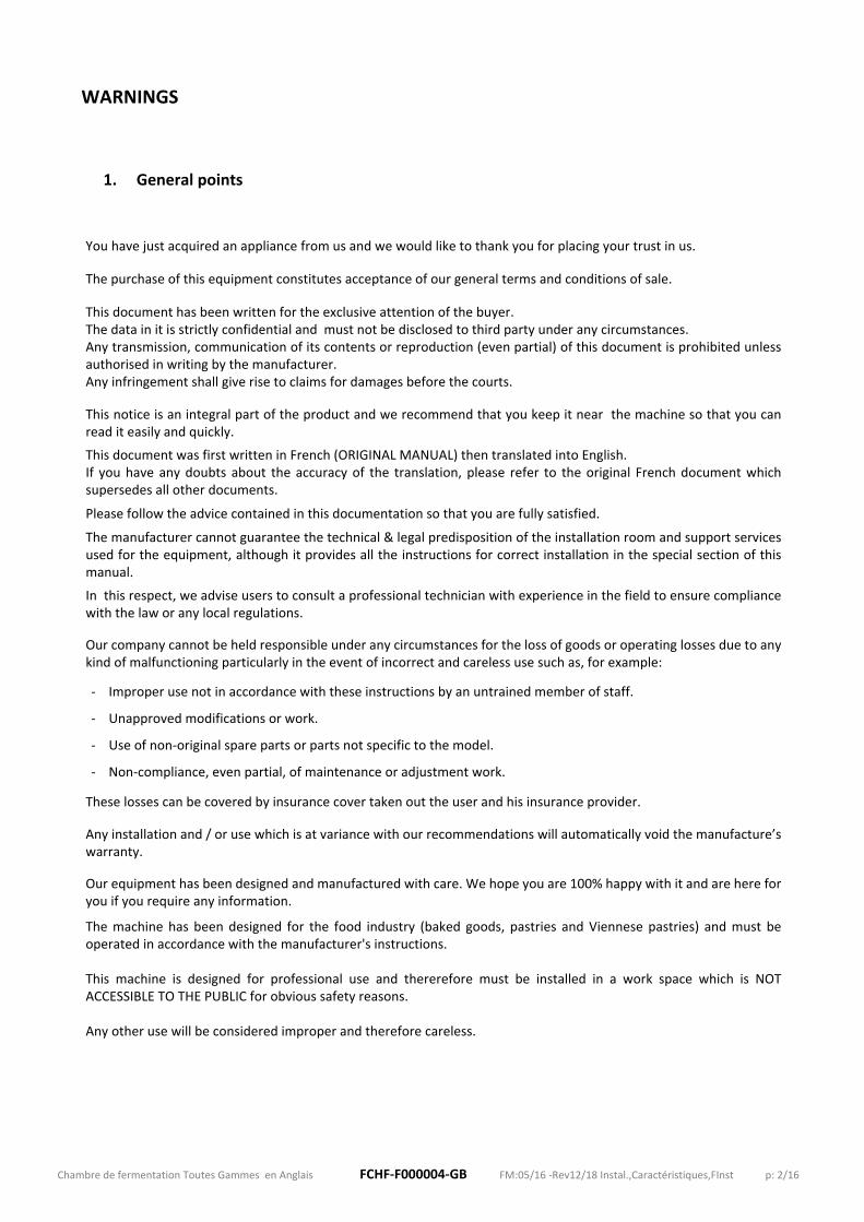
INSTALLATION
This machine is designed for professional use and thererefore must be installed in a work space which is NOTACCESSIBLE TO THE PUBLIC for obvious safety reasons.
Before the installation, make sure that :
The equipment must be set up on a flat floor, with a sufficient safety allowable load (The maximum allowable slope is5 mm/m).
The equipment shouldn’t be in touch with any wall. Keep at least 10 mm to avoid condensation problems.
The room lay‐out and the ventilation must comply with the legal standards.
The wall clearance at rear of the machine is at least 100 mm.
Important service area : service access to the technical part must be provided.
An adequate natural airflow must be provided around the equipment.
The appliance must be aerated in an ambient atmosphere below 32°C to ensure its proper operating.
Electric and hydraulic connections must comply with the applicable regulations and must be done by qualified workers.
1. Power supply
Each appliance must be individually protected with a system close to the appliance, easily accessible and in conformity with legislation.
Note : the EARTH continuity circuit must be provided between the appliance and its electrical connection.The customer must install a differential circuit breaker (1 per appliance). Be sure to ground the appliance. Do not connect the ground wire to gas or water pipes, lightning rods, or telephonegrounding lines. If the appliance is not properly grounded, electric shock may result.
The power supply voltage must match the indicated voltage specified on the nameplate.
Connection directly on the terminal block at customer’s charge.
2. Water supply
Appliances connected to drinking water supply must be equipped with means of protection against return to the drinking water circuit, and installed according to the national regulations in force.
Valve Ø 3/4” to 1 m above the floor, close to the equipment and easily accessible.Water pressure : 3 bars mini ‐ 5 bars maxiAt the output of this valve, pipes and connection need to be prepared.
Appliance supplied with a 2 m flexible stainless steel hose for water supply.
In case the water analysis results are critical, it is highly recommended to apply water treatment in order to avoid scaling
problems.
If your water does not meet the quality criteria indicated in the section «Water quality», it may cause a malfunction even the
degradation of the appliance. Non complying with our requirements may result in voiding the warranty.
Chambre de fermentation Toutes Gammes en Anglais FCHF‐F000004‐GB FM:05/16 ‐Rev12/18 Instal.,Caractéristiques,FInst p: 5/16
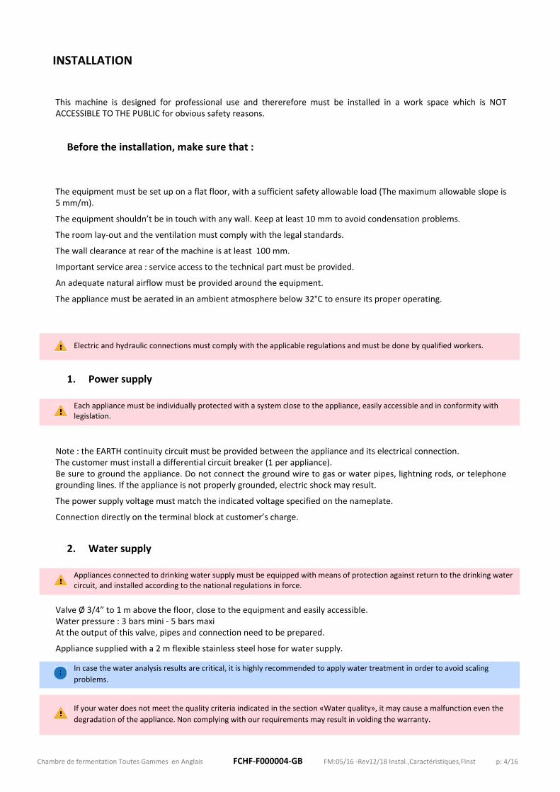
3. Safety thermostat
1 not adjustable safety thermostat located above the chamber.
4. Condensation Drain
Condensation Drain Ø 32mm to drill on the rear or side panel during the installation (length of drain tube supplied : 4m ). Condensate draining to the sewer by a tube Ø 40mm minimum or a channel in the floor of 100x100 mm.
Water coming from a condensation process is not drinkable because it is devoid of minerals and may contain bacteria. It is therefore unfit for human or animal consumption.
5. Panels
Injected sandwich panels in galvanised metal plate, white lacquered (stainless steel possible in option).Panels thickness : 68 mm. Inside and outside cladding scheduled for an easy cleaning and to resist to blows and scratches.
6. Hot air
Air diffusion by fans.Maximum temperature : 35°C (95°F).Normal using temperature: from 17 to 25°C (63°F to 77°F). This temperature has an influence on the finished productquality.
7. Hygrometry
Control panel eDrive : Hygrometry controlled by probe. Thermoregulator with digital display : Hygrostat adjustable from 30 to 100%.
8. Refrigeration unit
The refrigeration unit is cooled by air and use R452A as gas.
Cooling couplings : ‐ 1/2 ‐ 3/8 for the models : 1A ‐ 2A ‐ 1B ‐ 7/8 ‐ 1/2 for the models : 6C ‐ 6D ‐ 5/8 ‐ 3/8 for all others models
If the refrigeration unit is located remotely, it must be more powerful and pipes must be adapted accordingly (look at the paragraph : Remote refrigeration unit). In the case of a remote refrigeration unit, the specialist technician responsible for the refrigeration system will have to charge the refrigerant into the circuit according to the distance of the unit (the refrigeration unit is then delivered empty).
From factory, the refrigeration unit is loaded with R452A аs gas and the entire refrigerant line is set to operate with this gas. However, the unit remains compatible with R404A but under two conditions :‐ modifying of the different settings of the refrigeration line (adjustment for overheating)‐ the unit and the entire refrigeration line must be empty (gas mixing is forbidden).Before any gas change during a service intervention or when filling a remote unit, please contact your distributor to inquire about the procedure to be followed. Any change of gas during an intervention must be clearly identified on the machine (label) and the maintenance booklet must imperativeley stipulate this change of gas.

Chambre de fermentation Toutes Gammes en Anglais FCHF‐F000004‐GB FM:05/16 ‐Rev12/18 Instal.,Caractéristiques,FInst p: 6/16
WATER QUALITY
Although if clean and safe for consumption, the water supplied can have a bad taste (caused by the chlorine), becorrosive or cause calcareous deposits.
After analysis, when the water characteristics reach critical levels, it is imperative to install a water treatment systemupstream to increase the life duration of your equipment.
Depending on the concentrations of chloride, carbonate and the pH value, it may also be necessary to treat water toreduce the corrosion risks.
A system of water treatment is strongly recommended in the following cases :
‐ if the water hardness is greater than or equal to 15°f : Hard water. It is a calcareous water that generates a very important scale deposit especially in hot condition ( 60°C).
‐ if it is a very soft water (TH<9°f) and a pH more than or equal to 7 : Corrosive water termed aggressive. Aggressive water involves the metal rustThe soft water corrosiveness is increased when its pH is acidic.
‐ if the pH is less than 6,8 or more than 7,5
‐ for high concentrations of chlorides or nitrates.
Depending on water analysis results , various solutions are possible : neutralizing filters , water softener, activatedcarbon filters, ... A water treatment specialist will be able to propose you a solution in compliance with yourinstallation and based on the water analysis results.
Once the treatment system installed, check its effectiveness through further analysis of the water.
The regular system maintenance as per the manufacturer's recommendations is imperative to maintain permanently awater quality suitable with the equipment.
The sediments presence in water is another factor to take into consideration. In such a case, a mud filter has to beadded to the system.
If your water does not meet these quality criteria it may cause a malfunction even the degradation of the appliance. Non
complying with the above mentioned requirements may result in voiding the warranty.
N.B : The water hardness is its calcium and magnesium content. The hydrotimetric title (TH) is measured in French degrees (°f): 1°f = 4 mg of calcium + 2.4 mg of magnesium per liter.

Chambre de fermentation Toutes Gammes en Anglais FCHF‐F000004‐GB FM:05/16 ‐Rev12/18 Instal.,Caractéristiques,FInst p: 7/16
APPLIANCE CHARACTERISTICS
The chamber is composed as follows :
‐ Injected sandwich panels in galvanised metal plate, white lacquered (stainless steel possible in option) ‐ A door ‐ 1 Water solenoid valve ‐ 1 Safety thermostat (not adjustable) ‐ ‐‐‐ Evaporators (according to the chamber dimensions) ‐ 1 Refrigeration unit ‐ A touchscreen control panel (Hygrometry controlled by probe)
Options :
‐ Lighting ‐ Remote refrigeration unit ‐ Tropicalized unit ‐ Double door (Not possible on some models. Consult us) ‐ A control panel constituted by 3 controllers with digital displays + An hygrostat adjustable from 30 to 100%
Control of the following functions :
PreblockingBlockingProvingEnd of ProvingHoldingLighting (option)9 possible registered programs : ‐ 1 program «Direct cold» ‐ 1 program «Direct proving» ‐ 7 adaptable programs
+Switch (3 positions)
Blocking
Timer
Proving
Hygrostat (option)
Chambre de fermentation Toutes Gammes en Anglais FCHF‐F000004‐GB FM:05/16 ‐Rev12/18 Instal.,Caractéristiques,FInst p: 8/16
‐ Electrical protection :
‐‐> CHF‐PROTELECM (~1x230V+N+G)‐‐> CHF‐PROTELECT (~3x400V+N+G)
Electrical protection : This function is intended to protect the electrical equipment by ensuring a constant voltage regardless of
fluctuations in the mains voltage. The voltage control relay on the power supply line of the regulator trips if the mains voltage is outside the adjustment range for 6 seconds and automatically resets when the line voltage returns to its normal state.
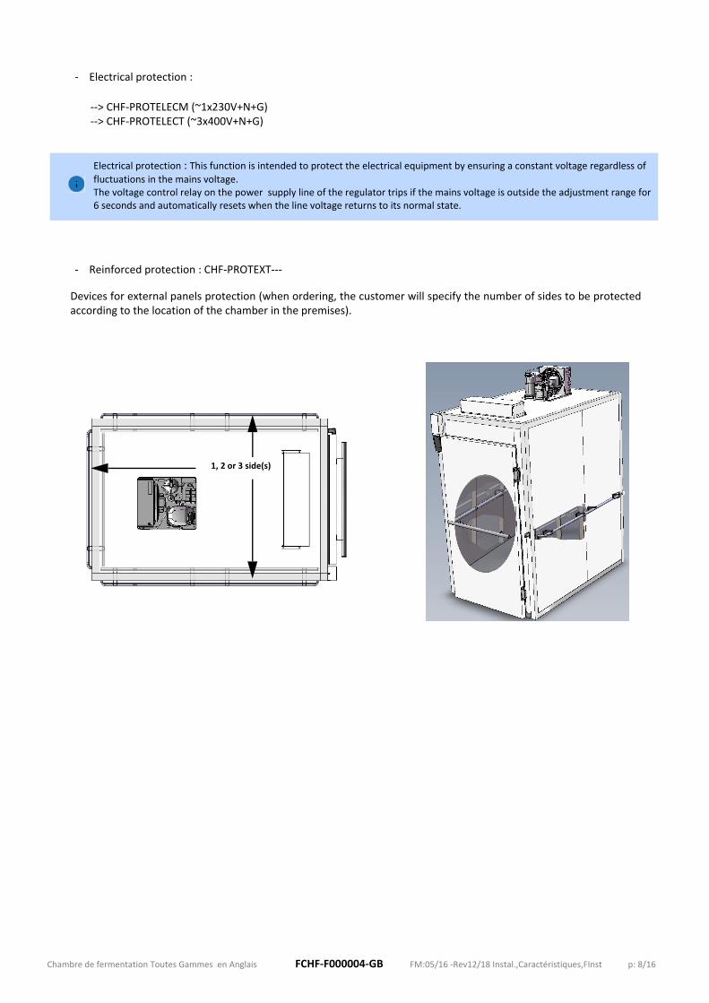
‐ Reinforced protection : CHF‐PROTEXT‐‐‐
Devices for external panels protection (when ordering, the customer will specify the number of sides to be protectedaccording to the location of the chamber in the premises).
1, 2 or 3 side(s)

Chambre de fermentation Toutes Gammes en Anglais FCHF‐F000004‐GB FM:05/16 ‐Rev12/18 Instal.,Caractéristiques,FInst p: 9/16
SPEC SHEET
Prover chamber ‐ Range A
Electric supply (must be connected directly on the terminal block)
Water solenoid valve Ø3/4M (2m of hose supplied)
Safety thermostat
Condensation Drain (4m of drain tube supplied)
Compressor location depends of prover type
Evaporator
a Touchscreen regulator ‐ E‐Drive
b Electro mechanical control panel
MODEL
CHF‐01A1
CHF‐02A1
CHF‐02A2
CHF‐03A1
CHF‐03A2
CHF‐04A1
CHF‐04A2
CHF‐05A1
CHF‐06A1
CHF‐06A2
8x10 12x10 8x18 16x10 8x26 20x10 12x18 12x24 12x32 16x18
Number of trolleys : 1 2 3 4 5 6
Voltage (V) / Frequency (Hz) : ~1x230V+N+G / 50 ~3x400V+N+G / 50
Intensity (A) : 13,4 14,7 23,2 23,5 23,2 19,4 21
Electrical power (kW) : 3,08 3,38 5,33 5,4 5,33 13,41 14,42
Heating power (kW) : 2x0,75 2x0,75 2x1,5 4x0,75 2x1,5 4x1,5
Power of the refrigeration unit (CV) : 1/2 5/8 1 1 1/4 1 1/2
Cooling capacity of the unit (W)*: 1112 1250 1516 2166 2752
Sound power (dB(A)) : 70 70 69 76
Cooling couplings (Ø) : 3/8 ‐ 1/4 1/2 ‐ 3/8 5/8 ‐ 3/8
Weight of the group (Kg) : 27,6 36 38 44
Gaz charge R‐452A (Kg) : 0,84 1,05 1,26 1,89 1,26 1,575 2,1
* these cooling capacities are given for an evaporation temperature of ‐10°C and intake and ambient temperatures of 32°C
DIMENSIONS mm
HT : 2613 2615 2720
L : 920 1320 920 1720 920 2120 1320 1320 1320 1720
P : 1120 1920 1120 2720 1120 1920 2520 3320 1920
Door : P1 P3 P1 P3
PO : 1889 2269 2684 1884 3484 1884 3064 3664 4464 3064
PF : 1272 1272 2072 1272 2872 1272 2072 2672 3472 2072
Li : 620 1000 620 1450 620 1900 1000 1400
Pi : 950 1750 850 2550 850 1700 2350 3150 1700
PG : 496 485 490 607
LG : 433 430 430 512
HG : 338 340 340 445
Unit centre‐to‐centre fixing distance : 310x385 310x385 310x385 326x190
R452A is a Fluorinated Greenhouse gas, covered by the Kyoto Protocol, with a Global Warming Potential (GWP) = 2141.
to drill on the rear or side panel during the installation.
Door :
Option : Double door
if Lpi = 1020 : PO=P+619if Lpi = 1420 : PO=P+819if Lpi = 1670 : PO=P+944
Not possible on some models. Consult us
Inlets and outlets are at customer’s charge and have to be in‐service the day of installation.
To avoid any scaling problems, it is IMPERATIVE to treat the water if the analysis results are critical.

Chambre de fermentation Toutes Gammes en Anglais FCHF‐F000004‐GB FM:05/16 ‐Rev12/18 Instal.,Caractéristiques,FInst p: 10/16
SPEC SHEET
Prover chamber ‐ Range B
Electric supply (must be connected directly on the terminal block)
Water solenoid valve Ø3/4M (2m of hose supplied)
Safety thermostat
Condensation Drain (4m of drain tube supplied)
Compressor location depends of prover type
Evaporator
a Touchscreen regulator ‐ E‐Drive
b Electro mechanical control panel
MODEL
CHF‐01B1
CHF‐02B1
CHF‐02B2
CHF‐03B1
CHF‐03B2
CHF‐04B1
CHF‐04B2
CHF‐04B3
CHF‐05B1
CHF‐05B2
CHF‐06B1
CHF06B2
CHF‐06B3
10x10 16x10 10x18 24x10 10x26 32x10 10x36 16x18 12x36 10x44 12x44 10x50 24x18
Number of trolleys : 1 2 3 4 5 6
Voltage (V) / Frequency (Hz) : ~1x230V+N+G / 50 ~3x400V+N+G / 50
Intensity (A) : 14,7 18,6 25,4 13,3 20,8
Electrical power (kW) : 3,38 4,28 5,84 9,24 14,4 12,7
Heating power (kW) : 2x0,75 2 2x1,5 4x0,75 4x1,5
Power of the refrigeration unit (CV) : 5/8 1 1 1/8 1 1/2 2
Cooling capacity of the unit (W)*: 1250 1516 1758 2752 3009
Sound power (dB(A)) : 70 69 69 76 77
Cooling couplings (Ø) : 1/2‐3/8 5/8 ‐ 3/8
Weight of the group (Kg) : 36 38 41 44 53
Gaz charge R‐452A (Kg) : 1,05 1,26 1,89 2,1
* these cooling capacities are given for an evaporation temperature of ‐10°C and intake and ambient temperatures of 32°C
DIMENSIONS mm
HT : 2615 2720 2721
L : 1120 1720 1120 2520 1120 3320 1120 1720 1320 1120 1320 1120 2520
P : 1120 1120 1920 1120 2720 1120 3720 1920 3720 4520 4520 5120 1920
Door : P2 P3 P2 P3 P2 P3 P2 P3 P2 P3 P2 P3
PO : 2064 2264 2864 2964 3664 2264 4664 3064 4864 5464 5464 6264 3064
PF : 1272 2072 1272 2872 1272 3872 2072 3872 4672 4672 5272 2072
Li : 800 1450 800 2250 800 3050 800 1400 1000 800 1000 800 2200
Pi : 950 850 1750 850 2550 850 3550 1700 3550 4350 4350 4950 1700
PG : 485 490 607 615
LG : 430 430 512 512
HG : 340 340 445 446
Unit centre‐to‐centre fixing distance : 310x385 310x385 326x190 430x190
R452A is a Fluorinated Greenhouse gas, covered by the Kyoto Protocol, with a Global Warming Potential (GWP) = 2141.
to drill on the rear or side panel during the installation
Door :
Option : Double door
if Lpi = 1020 : PO=P+619if Lpi = 1420 : PO=P+819if Lpi = 1670 : PO=P+944
Not possible on some models. Consult us
Inlets and outlets are at customer’s charge and have to be in‐service the day of installation.
To avoid any scaling problems, it is IMPERATIVE to treat the water if the analysis results are critical.
Chambre de fermentation Toutes Gammes en Anglais FCHF‐F000004‐GB FM:05/16 ‐Rev12/18 Instal.,Caractéristiques,FInst p: 11/16
SPEC SHEET
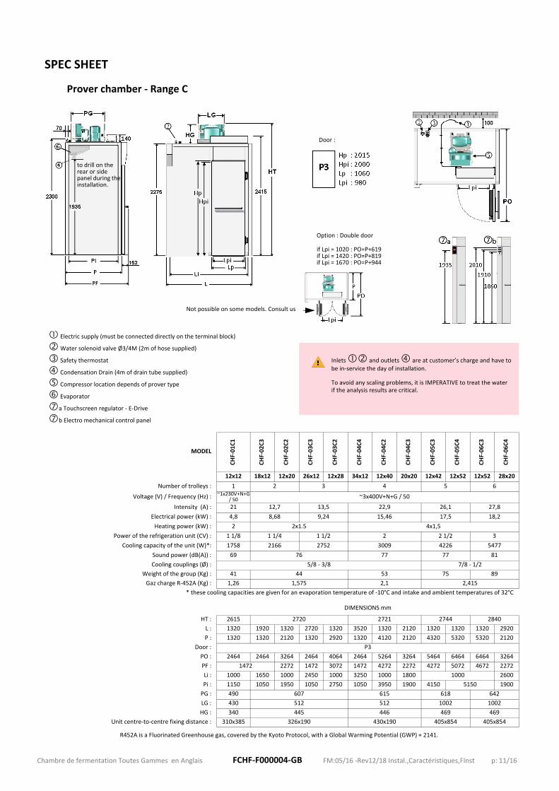
Prover chamber ‐ Range C
Electric supply (must be connected directly on the terminal block)
Water solenoid valve Ø3/4M (2m of hose supplied)
Safety thermostat
Condensation Drain (4m of drain tube supplied)
Compressor location depends of prover type
Evaporator
a Touchscreen regulator ‐ E‐Drive
b Electro mechanical control panel
MODEL
CHF‐01C1
CHF‐02C3
CHF‐02C2
CHF‐03C3
CHF‐03C2
CHF‐04C4
CHF‐04C2
CHF‐04C3
CHF‐05C3
CHF‐05C4
CHF‐06C3
CHF‐06C4
12x12 18x12 12x20 26x12 12x28 34x12 12x40 20x20 12x42 12x52 12x52 28x20
Number of trolleys : 1 2 3 4 5 6
Voltage (V) / Frequency (Hz) : ~1x230V+N+G / 50 ~3x400V+N+G / 50
Intensity (A) : 21 12,7 13,5 22,9 26,1 27,8
Electrical power (kW) : 4,8 8,68 9,24 15,46 17,5 18,2
Heating power (kW) : 2 2x1.5 4x1,5
Power of the refrigeration unit (CV) : 1 1/8 1 1/4 1 1/2 2 2 1/2 3
Cooling capacity of the unit (W)*: 1758 2166 2752 3009 4226 5477
Sound power (dB(A)) : 69 76 77 77 81
Cooling couplings (Ø) : 5/8 ‐ 3/8 7/8 ‐ 1/2
Weight of the group (Kg) : 41 44 53 75 89
Gaz charge R‐452A (Kg) : 1,26 1,575 2,1 2,415
* these cooling capacities are given for an evaporation temperature of ‐10°C and intake and ambient temperatures of 32°C
DIMENSIONS mm
HT : 2615 2720 2721 2744 2840
L : 1320 1920 1320 2720 1320 3520 1320 2120 1320 1320 1320 2920
P : 1320 1320 2120 1320 2920 1320 4120 2120 4320 5320 5320 2120
Door : P3
PO : 2464 2464 3264 2464 4064 2464 5264 3264 5464 6464 6464 3264
PF : 1472 2272 1472 3072 1472 4272 2272 4272 5072 4672 2272
Li : 1000 1650 1000 2450 1000 3250 1000 1800 1000 2600
Pi : 1150 1050 1950 1050 2750 1050 3950 1900 4150 5150 1900
PG : 490 607 615 618 642
LG : 430 512 512 1002 1002
HG : 340 445 446 469 469
Unit centre‐to‐centre fixing distance : 310x385 326x190 430x190 405x854 405x854
R452A is a Fluorinated Greenhouse gas, covered by the Kyoto Protocol, with a Global Warming Potential (GWP) = 2141.
to drill on the rear or side panel during the installation.
Door :
Option : Double door
if Lpi = 1020 : PO=P+619if Lpi = 1420 : PO=P+819if Lpi = 1670 : PO=P+944
Not possible on some models. Consult us
Inlets and outlets are at customer’s charge and have to be in‐service the day of installation.
To avoid any scaling problems, it is IMPERATIVE to treat the water if the analysis results are critical.

Chambre de fermentation Toutes Gammes en Anglais FCHF‐F000004‐GB FM:05/16 ‐Rev12/18 Instal.,Caractéristiques,FInst p: 12/16
SPEC SHEET
Prover chamber ‐ Range D
Electric supply (must be connected directly on the terminal block)
Water solenoid valve Ø3/4M (2m of hose supplied)
Safety thermostat
Condensation Drain (4m of drain tube supplied)
Compressor location depends of prover type
Evaporator
a Touchscreen regulator ‐ E‐Drive
b Electro mechanical control panel
MODEL
CHF‐02D1
CHF‐02D2
CHF‐03D1
CHF‐03D2
CHF‐04D1
CHF‐04D2
CHF‐04D3
CHF‐05D1
CHF‐05D2
CHF‐06D1
CHF06D2
CHF‐06D3
16x10 10x18 24x10 10x26 32x10 10x36 16x18 12x36 10x44 12x44 10x50 24x18
Number of trolleys : 2 3 4 5 6
Voltage (V) / Frequency (Hz) : ~3x400V+N+G / 50
Intensity (A) : 12,7 13,5 22,9 26,1 27,8
Electrical power (kW) : 8,68 9,24 15,46 17,5 18,2
Heating power (kW) : 2x1.5 4x1,5
Power of the refrigeration unit (CV) : 1 1/4 1 1/2 2 2 1/2 3
Cooling capacity of the unit (W)*: 2166 2752 3009 4226 5477
Sound power (dB(A)) : 76 77 77 81
Cooling couplings (Ø) : 5/8 ‐ 3/8 7/8 ‐ 1/2
Weight of the group (Kg) : 44 53 75 89
Gaz charge R‐452A (Kg) : 1,575 2,1 2,31 2,415
* these cooling capacities are given for an evaporation temperature of ‐10°C and intake and ambient temperatures of 32°C
DIMENSIONS mm
HT : 2720 2721 2744 2840
L : 1720 1120 2520 1120 3320 1120 1720 1320 1120 1320 1120 2520
P : 1120 1920 1120 2720 1120 3720 1920 3720 4520 4520 5120 1920
Door : P3 P2 P3 P2 P3 P2 P3 P2 P3 P2 P3
PO : 2264 2864 2964 3664 2264 4664 3064 4864 5464 5464 6264 3064
PF : 1272 2072 1272 2872 1272 3872 2072 3872 4672 4672 5272 2072
Li : 1450 800 2250 800 3050 800 1400 1000 800 1000 800 2200
Pi : 850 1750 850 2550 850 3550 1700 3550 4350 4350 4950 1700
PG : 607 615 618 642
LG : 512 512 1002 1002
HG : 445 446 469 469
Unit centre‐to‐centre fixing distance : 326x190 430x190 405x854 405x854
R452A is a Fluorinated Greenhouse gas, covered by the Kyoto Protocol, with a Global Warming Potential (GWP) = 2141.
to drill on the rear or side panel during the installation.
Door :
Option : Double door
if Lpi = 1020 : PO=P+619if Lpi = 1420 : PO=P+819if Lpi = 1670 : PO=P+944
Not possible on some models. Consult us
Inlets and outlets are at customer’s charge and have to be in‐service the day of installation.
To avoid any scaling problems, it is IMPERATIVE to treat the water if the analysis results are critical.

Chambre de fermentation Toutes Gammes en Anglais FCHF‐F000004‐GB FM:05/16 ‐Rev12/18 Instal.,Caractéristiques,FInst p: 13/16
SPEC SHEET
Prover chamber ‐ Range E
Electric supply (must be connected directly on the terminal block)
Water solenoid valve Ø3/4M (2m of hose supplied)
Safety thermostat
Condensation Drain (4m of drain tube supplied)
Compressor location depends of prover type
Evaporator
a Touchscreen regulator ‐ E‐Drive
b Electro mechanical control panel
MODEL
CHF‐01E1
CHF‐01E2
CHF‐02E1
CHF‐02E2
CHF‐02E3
CHF‐03E1
CHF‐03E2
CHF‐03E3
CHF‐04E1
CHF‐04E2
CHF‐04E3
CHF‐05E1
CHF05E2
CHF‐05E3
CHF‐06E1
CHF06E2
CHF‐06E3
8x8 10x8 8x16 10x12 14x10 8x22 10x18 18x10 8x30 10x24 24x10 8x36 10x28 30x10 8x44 10x34 36x10
Number of trolleys : 1 2 3 4 5 6
Voltage (V) / Frequency (Hz) : ~1x230V+N+G / 50 ~3x400V+N+G / 50
Intensity (A) : 14,7 18,6 25,6 13,5 12,7 15,6 13,3 22,3
Electrical power (kW) : 3,38 4,28 5,84 9,24 8,69 10,82 9,24 15,46
Heating power (kW) : 2x0,75 2 2x1,5 4x0,75 2x1,5 2x2 4x0,75 4x1,5
Power of the refrigeration unit (CV) : 5/8 1 1 1/8 1 1/2 1 1/4 1 1/2 2
Cooling capacity of the unit (W)*: 1250 1516 1758 2752 2166 2752 3009
Sound power (dB(A)) : 70 69 76 77
Cooling couplings (Ø) : 1/2‐3/8 5/8 ‐ 3/8
Weight of the group (Kg) : 36 38 41 44 53
Gaz charge R‐452A (Kg) : 1,05 1,26 1,89 1,575 1,89 2,1
* these cooling capacities are given for an evaporation temperature of ‐10°C and intake and ambient temperatures of 32°C
DIMENSIONS mm
HT : 2615 2720 2721
L : 920 1120 920 1120 1520 920 1120 1920 920 1120 2520 920 1120 3120 920 1120 3720
P : 920 920 1720 1320 1120 2320 1920 1120 3120 2520 1120 3720 2920 1120 4520 3520 1120
Door : P1 P2 P1 P2 P2 P1 P2 P3 P1 P2 P3 P1 P2 P3 P1 P2 P3
PO : 1740 1920 2540 2320 2120 3140 2920 2320 3940 3520 2320 4540 3920 2320 5340 4520 2320
PF : 1072 1072 1872 1472 1272 2472 2072 1272 3272 2672 1272 3872 3072 1272 4672 3672 1272
Li : 620 800 620 800 1250 620 800 1650 620 800 2250 620 800 2850 620 800 3450
Pi : 750 750 1550 1157 867 2150 1750 850 2950 2350 850 3550 2750 850 4350 3350 850
PG : 485 490 607 615
LG : 430 430 512 512
HG : 340 340 445 446
Unit centre‐to‐centre fixing distance : 385x310 310x385 326x190 430x190
R452A is a Fluorinated Greenhouse gas, covered by the Kyoto Protocol, with a Global Warming Potential (GWP) = 2141.
to drill on the rear or side panel during the installation.
Door :
Option : Double doorif Lpi = 1020 : PO=P+619if Lpi = 1420 : PO=P+819if Lpi = 1670 : PO=P+944
Not possible on some models. Consult us
Inlets and outlets are at customer’s charge and have to be in‐service the day of installation.
To avoid any scaling problems, it is IMPERATIVE to treat the water if the analysis results are critical.

Chambre de fermentation Toutes Gammes en Anglais FCHF‐F000004‐GB FM:05/16 ‐Rev12/18 Instal.,Caractéristiques,FInst p: 14/16
REAR VIEW / CONNECTIONS PRINCIPLE
① Electric supply
② Safety thermostat
③ Water solenoid valve
④ Condensation Drain
⑤ Refrigeration unit
Not supplied with the chamber : must be connected directly on the terminal block
1x2m (15‐21 / 20‐27)
Supplied with the chamber

Chambre de fermentation Toutes Gammes en Anglais FCHF‐F000004‐GB FM:05/16 ‐Rev12/18 Instal.,Caractéristiques,FInst p: 15/16
JUXTAPOSITION OF SEVERAL CHAMBERS
These chambers can be juxtaposed with a shared panel

Chambre de fermentation Toutes Gammes en Anglais FCHF‐F000004‐GB FM:05/16 ‐Rev12/18 Instal.,Caractéristiques,FInst p: 16/16
577, rue Célestin Hennion CS 7002959144 Gommegnies ‐ France
Tel : +33.(0)3.27.28.18.18Fax : +33.(0)3.27.49.80.41