Embed Size (px)
Citation preview
Revision A 9/2011
FTE-6000 Hand Held Tuneable Laser Source
USER’S MANUAL
Avoid Exposure Laser Radiation Emitted
From The Aperture This product conforms to CDRH standards for laser product
Per 21 CFR 1040.10 & 1040.11

Revision A 9/2011

Revision A 9/2011
Table of Contents SECTION PAGE 1.0 Safety………..…………………...……………..……….……………….......……………………………1 1.1 General Safety 1.2 Laser Safety 1.3 Fiber Optic Connection 1.4 Power Supply 2.0 FTE-6000 Quick Start……………………..………….…………...........................……………………2 3.0 Introduction ……………………………………..………………………………………….……………..3 4.0 Preparation for Use ………………………………………………………………………………...……4 4.1 Inspection 4.2 Instrument Identification / Configuration 4.3 Power Requirements 5.0 Description……………......……….………………………………….…………...………..……………..5 5.1 Mechanical Instrument Enclosure 5.2 Physical Front Panel Top Plate Bottom Plate 5.3 Display 5.4 Icon Definitions 6.0 Feature/Preference Description and Settings ………….………………..……...……….……..……...8 6.1 Feature Description and Operations Battery Level/Power Indicator Help USB Flash Drive USB/PC Operating Temperature 6.1 User Preferences Brightness Setting Speaker
I

Revision A 9/2011
7.0 Operation…………………………..………………………………...……….……………..…………..…9 7.1 Key Pad 7.2 Power On 7.3 Display Units 7.4 Setting 1st Channel 7.5 Setting Sweep Parameters Step Size Power Level (dBm) Dwell Time Sweep Span Continuous / Single Sweep 7.6 Start Sweep Laser Activity Indicator Pause Sweep Temporary Change of Start Channel
7.7 Single Channel Operation Manual Adjust Method Lambda Button Method
8.0 Maintenance ……………………………………………………………………..…….…………………… 14 10.1 Battery Replacement 10.2 Recalibration and Verification 10.3 Adapter Replacement 9.0 Specifications …………………….………….……………………..……….……….……………………..15 10.0 Warranty and Repair………………………………….…………………….….....….…………………...16 11.0 Warranty Information Repair Information 11.0 Trouble Shooting………………………………...………….……………..………………….……..……17 12.0 Version Control………….….…………….………………………….....………………………..………..18
II

Revision A 9/2011
1.0 Safety
CAUTION: Please Read This Prior To Operation
1.1 General Safety This product has been designed and tested in accordance with the Manufacturer’s safety standards and has been supplied in a safe condition.
This document contains information and warnings that must be followed by the user to ensure safe operation and to maintain the product in a safe condition.
1.2 Laser Safety The Tuneable Laser Source has been configured to provide laser radiation at wavelengths from 1520nm to 1608nm. See warning label in figure 1.1 (also displayed in the upper middle section of the back panel on the FTE-6000). The unit has been designed to comply with 21 CFR (Code of Federal Regulations) 1040.10 and 1040.11, for Class 1M emission limits. Although Class 1 levels are not considered to be hazardous, we suggest limiting exposure by never looking directly into the Fig 1.1 laser aperture. Also, do not under any circumstance view or inspect the laser output fibers, connectors or the fiber under test through collimating or focusing optics unless the unit is turned off, batteries are removed and the power adapter is disconnected.
1.3 Fiber Optic Connection Fiber-optic connectors are easily contaminated or damaged. The connection to the FTE-6000 is a physical contact type of connection and dirty or damaged connectors will impair the instrument’s capabilities at the minimum and at worst result in the need to return the equipment to the factory for expensive repairs.
1.4 Power Supply To Prevent Fire or Shock Hazard: Do not install battery types other than those supplied by the manufacturer; Do not use the charger without the batteries installed. Do not expose the battery charger to rain or excessive moisture. Do not use the AC adapter when there are signs of damage to the enclosure or cord. Do not use any other charger than the one provided with this instrument. Any other condition will void the warranty.
1
WARNING: Never clean or look directly into the fiber optic connector or the end of fiber attached to the Tunable Laser Source while it is energized, to do so will expose the user to laser radiation and could result in personal injury or instrument damage. Never activate the laser without attaching a fiber to the fiber output port.
WARNING: Before connecting a fiber to the TLS, be certain the fiber has no other active optical sources or sensitive instruments connected to the other end. Feeding power back into the TLS could result in damage or the TLS could damage equipment not designed to receive its signal. This action could result in voiding the warranty.
Caution: Prior to making any connection to the unit ensure that all proper cleaning procedures have been followed.
Revision A 9/2011
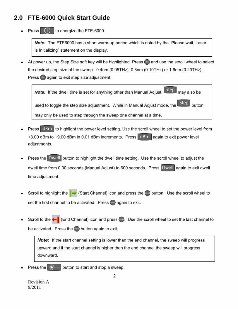
2.0 FTE-6000 Quick Start Guide
Press to energize the FTE-6000.
At power up, the Step Size soft key will be highlighted. Press and use the scroll wheel to select
the desired step size of the sweep. 0.4nm (0.05THz), 0.8nm (0.10THz) or 1.6nm (0.20THz).
Press again to exit step size adjustment.
Press to highlight the power level setting. Use the scroll wheel to set the power level from
+3.00 dBm to +9.00 dBm in 0.01 dBm increments. Press again to exit power level
adjustments.
Press the button to highlight the dwell time setting. Use the scroll wheel to adjust the
dwell time from 0.00 seconds (Manual Adjust) to 600 seconds. Press again to exit dwell
time adjustment.
Scroll to highlight the (Start Channel) icon and press the button. Use the scroll wheel to
set the first channel to be activated. Press again to exit.
Scroll to the (End Channel) icon and press . Use the scroll wheel to set the last channel to
be activated. Press the button again to exit.
Press the button to start and stop a sweep.
2
Note: The FTE6000 has a short warm-up period which is noted by the “Please wait, Laser
is Initializing” statement on the display.
Note: If the start channel setting is lower than the end channel, the sweep will progress
upward and if the start channel is higher than the end channel the sweep will progress
downward.
Note: If the dwell time is set for anything other than Manual Adjust, may also be
used to toggle the step size adjustment. While in Manual Adjust mode, the button
may only be used to step through the sweep one channel at a time.

Revision A 9/2011
3.0 Introduction The TTI FTE-6000 Series Hand Held Tuneable Laser Source is offered in two versions, “C” Band (1529–
1563nm) and “L”-band (1569 -1607nm). It has adjustable output power with a resolution of 0.01 dB.
Power levels range from +3 dBm to +9 dBm. Step size, power level and dwell time are adjustable
settings to optimize sweep parameters. Single or continuous sweeps may be programmed. Selection of
the first and last channels to be activated may also be programmed. The channels may be displayed in
either wavelength or frequency and the wavelength/frequency associated with the first channel is user
settable. The unit has a 4 inch color TFT Display and the FTE-6000 may be operated as a virtual
instrument using the TTI CertSoft Windows™ compatible certification software suite. The FTE-6000 is
housed in a rugged metal enclosure with a robust protective boot. These units are designed for field use
and are extremely user friendly.
3

Revision A 9/2011
4.0 Preparation for Use 4.1 Inspection Before shipment, this instrument has been inspected and found to be in perfect working order and free of defects. The shipping carton contains the following:
1. Hand Held Tuneable Laser Source, with protective boot and 8-AA NiMH batteries installed 2. Universal AC/DC charger with interchangeable mains plugs 3. USB cable 4. Manual and software on CD 5. Set of interchangeable adapters, SC and FC. (Shipped with FC adapter installed)
4.2 Instrument Identification/ Configuration The instrument’s Model, Part Number, Serial Number and Date of Manufacture are indicated on a label located on the bottom plate of the unit. The instrument’s history is filed at the factory by part number and serial number.
4.3 Power Requirements Fig 4.1
The FTE-6000 is equipped with a 100-240V-0.4A input universal battery charger with 13.6V, 0.75A, (center positive output). The charger is supplied with interchangeable mains plugs for North America, Great Britain, Europe and Australia. The unit’s internal power pack is comprised of eight AA NiMH cells with a capacity of 2700mA hours. Depending on usage, a fully charged battery pack will provide approximately 4 hrs of operation. Typically, fully discharged batteries require 6 - 8 hours of recharging. Battery replacement is not recommended. However if you must replace the batteries follow the following procedure. Unplug the external power supply and carefully remove unit from its protective boot. Remove two screws each from the top and bottom plates. These retain the back cover. Carefully remove the back cover and remove the two screws that hold the two battery covers in place. Replace only with high quality AA NiMH batteries. If you install NiMH batteries that are discharged, charge these batteries for at least one hour before using the FTE-6000. For maintenance, batteries require a monthly periodic recharge.
4
WARNING: To Prevent Fire or Shock Hazard: Do not install other battery types. Do not use the charger without the batteries installed. Do not expose the battery charger to rain or excessive moisture. Do not use the AC adapter when there are signs of damage to the enclosure or cord. Do not use any charger other than the one provided with this instrument. Any other condition will void the warranty.

Revision A 9/2011
5.0 Description
5.1 Mechanical Instrument Enclosure
The TLS is packaged in a rugged aluminum housing which is further protected with a rubberized boot. Although the front panel is weather resistant, reasonable care should be taken to avoid liquids and contaminants around the fragile optical and electrical connectors, and the LCD display. Use a mild cleaning agent and damp soft cloth to clean the panels and the outside case. Refer to the maintenance section to clean the optical connector. NEVER open the instrument for cleaning. Return to the factory for servicing if necessary.
5.2 Physical Front Panel Charge Indicator Display Key Pad Scroll Wheel
Fig 5.1
5

Revision A 9/2011
Top Plate
Bottom Plate
Fig 5.2 5.3 Display
Fig 5.3 6
Temperature Status
Channel Information
Battery Indicator
Sweep Parameters
Icon Bar
Laser Status
Active Wavelength/Frequency
Soft Keys
USB Flash
USB PC
Power Jack
Optical Signal Output
Revision A 9/2011
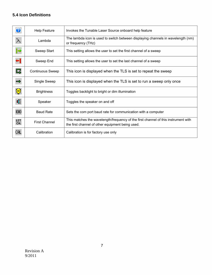
5.4 Icon Definitions
7
Help Feature Invokes the Tunable Laser Source onboard help feature
Lambda The lambda icon is used to switch between displaying channels in wavelength (nm) or frequency (THz)
Sweep Start This setting allows the user to set the first channel of a sweep
Sweep End This setting allows the user to set the last channel of a sweep
Continuous Sweep This icon is displayed when the TLS is set to repeat the sweep
Single Sweep This icon is displayed when the TLS is set to run a sweep only once
Brightness Toggles backlight to bright or dim illumination
Speaker Toggles the speaker on and off
Baud Rate Sets the com port baud rate for communication with a computer
First Channel This matches the wavelength/frequency of the first channel of this instrument with the first channel of other equipment being used.
Calibration Calibration is for factory use only
Revision A 9/2011
6.0 Feature / Preference Description and Settings
6.1 Feature Description and Operation The scroll wheel is used to select soft keys and/or icons unless a sweep parameter is highlighted. Battery Level/Power Indicator The bottom right hand corner of the screen shows the battery level and charge indicator. In the final hour of operation the battery will change to red. A warning indicator will sound a few minutes before the instrument automatically turns off. Ensure that the unit is turned off when plugging in the Battery Charger. Help The Tunable Laser Source has an onboard help feature. To access this help feature, use the scroll wheel to highlight the help icon and press Select to display the help menu. Scroll to the desired topic and press Select. Use the scroll wheel to move down the help page. To exit the help feature, scroll to exit at the bottom of the topic list and press Select. USB Flash Drive USB Flash drive is non-operational and included for future enhancements. USB/PC Located on the bottom panel is the USB/PC port which may be used to connect the TLS to a computer in order to operate in virtual mode with the CertSoft Windows™ compatible software suite. Operating Temperature The FTE-6000 is designed to operate at ambient temperatures from -10 to 40 C. On the left side of the display is a temperature gauge. This monitors the temperature of the laser. The unit should not be operated if the temperature rises into the red zone. If the temperature does rise out of the green zone of the scale, power down the instrument and allow it to cool prior to continuing.
6.2 User Preference Settings Brightness Setting Scroll to the Backlight icon. Press the Select button to toggle the back light to either bright or dim. Speaker Scroll to the Speaker icon. Press the Select button to toggle the speaker on and off.
8
Revision A 9/2011
7.0 FTE-6000 Operation
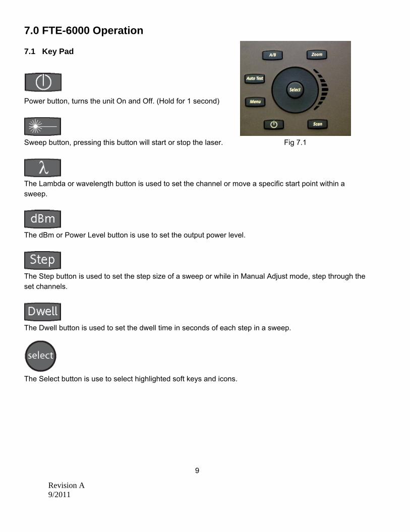
7.1 Key Pad
Power button, turns the unit On and Off. (Hold for 1 second)
Sweep button, pressing this button will start or stop the laser. Fig 7.1
The Lambda or wavelength button is used to set the channel or move a specific start point within a sweep.
The dBm or Power Level button is use to set the output power level.
The Step button is used to set the step size of a sweep or while in Manual Adjust mode, step through the set channels.
The Dwell button is used to set the dwell time in seconds of each step in a sweep.
The Select button is use to select highlighted soft keys and icons.
9
Revision A 9/2011
7.2 Power On Press the power button for one second to energize the FTE6000. 7.3 Display Units The output channel may be displayed in wavelength or frequency. To set the units, use the scroll wheel to highlight the Lambda (λ) Icon, press Select to toggle between wavelength (nm) and frequency (THz). This also changes the units display for step size, sweep begin and sweep end. 7.4 Setting the 1st Channel The wavelength/frequency of the first channel on the FTE-6000 may be set to match the first channels of other test equipment. Use the scroll wheel to highlight the 1st channel icon and press Select. Set the wavelength/frequency to be shown as channel number one. Press the Select button, use the scroll wheel to select desire action and press Select again. 7.5 Setting Sweep Parameters Step Size
There are three available step sizes, 0.4nm (0.05THz), 0.8nm (0.10THz) and 1.6nm (0.20THz). To set the step size, press the Step button and use the scroll wheel to make your selection. Press the Step button a second time to exit. The step size may also be adjusted by means of the Step Size soft key. Use the scroll wheel to highlight the Step Size soft key, press select and use the scroll wheel to set the desired step size. Press Select a second time to exit.
When the dwell time is set to Manual Adjust, the Step button increases the channel up or down the scale, depending on the start and end channel settings.
10
Note: When the dwell time is set to Manual Adjust, the soft key method is the only method available for setting step size.
WARNING: Fiber-optic connectors are easily contaminated or damaged. The connection
to the FTE-6000 is a physical contact type of connection and dirty or damaged connectors may impair the instrument’s capabilities at the minimum and at worst result in the need to return the FTE-6000 to the factory for repairs. Prior to making any connection to the unit, ensure that all proper cleaning procedures have been followed.

Revision A 9/2011
Power Level (dBm)
The power level of the signal is adjustable from +3.00 to +9.00 dBm in increments of 0.01 dBm. To set the power level, press the dBm button, use the scroll wheel to adjust the power and press the select button a second time to exit. This may also be accomplished by using the Power Level soft key. Use the scroll wheel to highlight the Power Level Soft Key, press select, use the scroll wheel to set the power and press Select a second time to exit.
Dwell Time
The duration of each step may be adjusted with the Dwell button. The dwell time range ranges from 0.00 seconds (Manual Adjust) to 600 seconds. To set the dwell time, press the Dwell button, use the scroll wheel to set the time and press the Dwell button a second time to exit. This may also be accomplished by using the Dwell Time soft key. Use the scroll wheel to highlight the Dwell Time Soft Key, press select, use the scroll wheel to set the power level and press Select a second time to exit. Sweep Span
The span of a sweep may be limited with the Sweep Begin and Sweep End icons. The sweep start channel is indicated in the lower left corner of the display in green and the sweep end channel is indicated in the lower right corner of the display in red. To set the start and end channels use the scroll wheel to highlight the span start or end icon, press the Select button to highlight the appropriate indicator, use the scroll wheel to adjust the setting and press the Select button again to exit. Continuous / Single Sweep
A sweep may be set to run continuously or to run though one time and stop. This is indicated in the icon bar by the continuous or single sweep icons. To change this setting, use the scroll wheel to high the indicated icon and press Select to switch to the opposite setting.
7.6 Start Sweep Once the desire parameters have been established the Sweep button may be pressed to start and stop a sweep. The progression of the sweep is indicated in the lower middle of the display with a progress bar.
11
Note: If the start channel setting is lower than the end channel, the sweep will progress
upward and if the start channel is higher than the end channel the sweep will progress downward.
Revision A 9/2011
Laser Activity Indicator
Laser activity is indicated by the blinking laser symbol just below the active wavelength/frequency in the center of the display. When the laser is off, the red octagon with “OFF” is displayed in the place of the Laser symbol.
Pause a sweep
Press the Lambda button at any point in a sweep to pause at that channel. The scroll wheel may be used in this state to move up or down the channels. Press the Lambda button again to continue the sweep. Temporary Change of Start Channel
To temporarily change the start channel with the laser inactive, press the Lambda button and use the scroll wheel to set the first channel to be output. When the laser is turned on, the sweep will start at the channel selected. 7.7 Single Channel Operation There are two methods to operate at a single channel. Manual Adjust
Set the Dwell to Manual Adjust. Press the Lambda button to highlight the wavelength/frequency. Use the scroll wheel to select a channel and press the Lambda button to exit. Press the Laser button to fire the laser.
12
WARNING: Before connecting to a patch cord or fiber under test, be certain the fiber has no active optical sources or instruments connected to the other end. Skin or eye damage could result from other high power sources e.g. EDFAs, or instrument damage could occur voiding the warranty.
WARNING: Even if the indicator shows the laser to be off never looking into the end of a fiber connected to the TLS or directly into the connector port. Do not under any circumstance view or inspect the laser output fibers, connectors or the fiber under test through collimating or focusing optics unless the unit is turned off, batteries are removed and the power adapter is disconnected.
Note: The wavelength/frequency displayed in the center of the display is an absolute value. The Channel number associated with the wavelength is a user settable value by using the 1st Channel Selection icon. This setting is stored in nonvolatile memory.
WARNING: Never clean or look directly into the fiber optic connector or the end of fiber attached to the Tunable Laser Source while it is energized, to do so will expose the user to laser radiation and could result in personal injury or instrument damage.
Revision A 9/2011
Lambda Button
Press the Lambda button to highlight the wavelength/frequency. Use the scroll wheel to through the channels within the parameters of the start and end sweep settings. Leave the wavelength/frequency highlighted and press the laser button. The selected channel will be output. Use the scroll wheel to cycle through the channels or select another channel while the laser is firing. The sweep function is halted when wavelength/frequency is highlighted. 13

Revision A 9/2011
8.0 Maintenance
8.1 Battery Replacement Battery replacement is not recommended. However if you must replace the batteries follow the following procedure. Unplug the external power supply and carefully remove unit from its protective boot. Remove two screws each from the top and bottom plates. These retain the back cover. Carefully remove back cover and remove the two screws that hold the two battery covers in place. Replace only with high quality AA NiMH batteries. If you install NiMH batteries that are discharged, charge these batteries for at least one hour before using the FTE-6000. For maintenance, batteries require a monthly periodic recharge. For maintenance, the batteries require a monthly periodic recharge.
8.2 Recalibration and Verification Periodic verification of the TLS is recommended to ensure that your instrument remains within specification. Although not imperative, we recommend a verification and optical connector check once a year to make certain the instrument is functioning properly and performing to its rated specifications. Consult the factory for service.
8.3 Adapter Replacement The FTE-6000 is supplied with two easily interchangeable adapters per port, SC/FC. To change an adapter, remove the two screws that hold the adapter in place, pull the adapter straight up from ferrule. It is suggested that you clean the exposed ferrule with an appropriate cleaner and lint free wipes anytime you replace the ferrule.
14
WARNING: To Prevent Fire or Shock Hazard: Do not install other battery types. Do not use the charger without the batteries installed. Do not expose the battery charger to rain or excessive moisture. Do not use the AC adapter when there are signs of damage to the enclosure or cord. Do not use any charger other than the one provided with this instrument. Any other condition will void the warranty.
Note: In order to maintain a low loss fiber connection, care should be taken to adequately clean the ferrule of any connector to be connected to the FTE-6000. In the event that the port needs to be cleaned, the first step is to be certain the instrument is off. We suggest the use of isopropyl alcohol and foam swabs specifically designed for cleaning connectors accepting 2.5 mm ferrules.
NOTE: When replacing the adapter with one that does not have a chained protective cap,
use the small screw in place of the larger screw that retains the end of the chain to the adapter base.
Revision A 9/2011
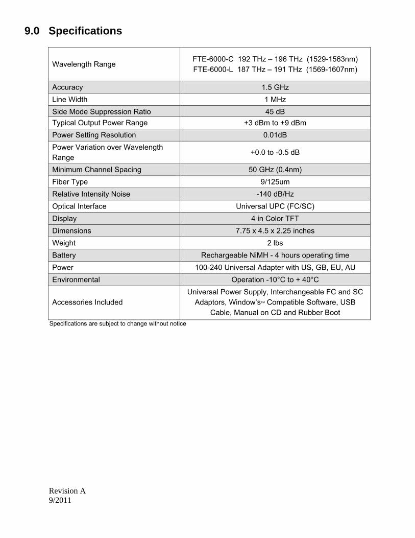
9.0 Specifications
Wavelength Range FTE-6000-C 192 THz – 196 THz (1529-1563nm) FTE-6000-L 187 THz – 191 THz (1569-1607nm)
Accuracy 1.5 GHz
Line Width 1 MHz
Side Mode Suppression Ratio 45 dB
Typical Output Power Range +3 dBm to +9 dBm
Power Setting Resolution 0.01dB
Power Variation over Wavelength Range
+0.0 to -0.5 dB
Minimum Channel Spacing 50 GHz (0.4nm)
Fiber Type 9/125um
Relative Intensity Noise -140 dB/Hz
Optical Interface Universal UPC (FC/SC)
Display 4 in Color TFT
Dimensions 7.75 x 4.5 x 2.25 inches
Weight 2 lbs
Battery Rechargeable NiMH - 4 hours operating time
Power 100-240 Universal Adapter with US, GB, EU, AU
Environmental Operation -10°C to + 40°C
Accessories Included
Universal Power Supply, Interchangeable FC and SC Adaptors, Window’sTM Compatible Software, USB
Cable, Manual on CD and Rubber Boot
Specifications are subject to change without notice

Revision A 9/2011
15
10.0 Warranty and Repair
10.1 Warranty Information This product, including all mechanical, electrical, and optical parts and assemblies are unconditionally warranted to be free of defects in workmanship and material for a period of one (1) year from the date of delivery. This warranty does not apply to expendable parts such as batteries, nor to any instrument or component which has been subjected to misuse, alteration, or fiber connector damage. It is the customer’s responsibility to understand all the instructions and specifications prior to operating this instrument. This warranty does not extend to any loss or damage consequent to the failure of the warranted product.
10.2 Repair Information If repair is required, contact Terahertz Technologies Inc. at +1 315-736-3642 or [email protected] for return instructions and a RMA number.

Revision A 9/2011
16
11.0 Trouble Shooting
Symptom Possible Cause Solution
LCD dark
Power not on Batteries require recharging Batteries are missing, in backwards or need replacement
Press ON/OFF key Recharge batteries Check polarity, replace batteries, or contact factory for servicing
LCD white Power cycled too quickly Turn off wait 5 seconds – turn on
Instrument locked Up
Unexpected Operational Mode
Turn off (hold ON/OFF button in for 1 second) wait 5 seconds – then depress On/Off again button to turn the unit on.
Low or no power being displayed
Defective cord or dirty connector Fiber Output port requires cleaning Angle polish mated with UPC polish
Replace or clean cord Clean and inspect port Examine connector ends
USB connection to PC not functioning properly
USB baud rate not set properly or too quick for computer PC drivers not set properly
Set port baud rate properly or decrease Baud rate in instrument and certification software Uninstall & reinstall certification software and drivers

Revision A 9/2011
17
12.0 Version Control Through a program of continuous improvement, we upgrade the features and performance of the instrument in an on going process. The instrument firmware version is accessible at “turn-on” on the bottom right-hand corner of the display. The version changes and approximate release dates are as follows. V1.0 – 9/2011 - Original release - Requires version 1.0 software ©TTI 2011

Revision A 9/2011
18