Embed Size (px)
Citation preview
Use of FTDI devices in life support and/or safety applications is entirely at the user’s risk, and the user agrees to defend, indemnify and hold FTDI harmless from any and all damages, claims, suits
or expense resulting from such use.
Future Technology Devices International Limited (FTDI) Unit 1, 2 Seaward Place, Glasgow G41 1HH, United Kingdom Tel.: +44 (0) 141 429 2777 Fax: + 44 (0) 141 429 2758
Web Site: http://ftdichip.com Copyright © 2013 Future Technology Devices International Limited
Application Note
AN_275
FT800 Example with Arduino
Version 1.0
Issue Date: 2013-11-25
The FTDI FT800 video controller offers a low cost solution for embedded graphics requirements. In addition to the graphics, resistive touch inputs and an audio output provide a complete human machine interface to the outside
world.
This application note will provide a simple example of developing Arduino Sketch code to control the FT800 over SPI. The principles demonstrated can then be used to produce more complex applications.
Application Note
AN_275 FT800 Example with Arduino Version 1.0
Document Reference No.: FT_000936 Clearance No.: FTDI# 367
1 Copyright © 2013 Future Technology Devices International Limited
Table of Contents
1 Introduction .................................................................................................................................... 2
2 Software Architecture ..................................................................................................................... 3
2.1 FT800.h .................................................................................................................................... 3
2.2 AN_275.ino ............................................................................................................................. 3
3 User Application .............................................................................................................................. 4
3.1 FT800 Graphics Rendering ...................................................................................................... 4
3.1.1 Display List ...................................................................................................................... 4
3.1.2 Co-Processor ................................................................................................................... 4
3.2 Arduino Sketch ........................................................................................................................ 5
3.2.1 setup() ............................................................................................................................. 5
3.2.2 loop() ............................................................................................................................... 6
3.2.3 Other functions ............................................................................................................... 7
4 Hardware ........................................................................................................................................ 8
5 Conclusion ..................................................................................................................................... 10
6 Contact Information ...................................................................................................................... 11
Appendix A – References ...................................................................................................................... 12
Document References ....................................................................................................................... 12
Acronyms and Abbreviations ............................................................................................................ 12
Appendix B – List of Tables & Figures ................................................................................................... 13
List of Tables ..................................................................................................................................... 13
List of Figures .................................................................................................................................... 13
Appendix C – Revision History .............................................................................................................. 14

Application Note
AN_275 FT800 Example with Arduino Version 1.0
Document Reference No.: FT_000936 Clearance No.: FTDI# 367
2 Copyright © 2013 Future Technology Devices International Limited
1 Introduction
The FT800 is a peripheral to a main system processor which provides a low-cost, yet complete, human interface experience by the incorporation of graphics rendering, touch screen sensing and audio capabilities. It is controlled over a low-bandwidth SPI or I2C interface allowing practically any microcontroller to be used.
For this application, an Arduino board is coupled with the VM800C43A-D,
FT800 development kit and the Arduino Sketch development environment. The target application demonstrates the use of the standard Arduino libraries to initialize and display different elements on the LCD of the VM800C. The design flow follows concepts introduced in application note AN_240 FT800 From the Ground Up.
Once these concepts are mastered, this example can be used as a basis for
larger and more complex applications that the FT800 has to offer:
graphics primitives (e.g. lines, shapes, text), inbuilt widgets (e.g. sliders, switches, dials), touch events and audio output.
Note: It is recommended to view the code while reading this application note.
Application Note
AN_275 FT800 Example with Arduino Version 1.0
Document Reference No.: FT_000936 Clearance No.: FTDI# 367
3 Copyright © 2013 Future Technology Devices International Limited
2 Software Architecture
This project consists of two files:
FT800.h – a header file containing all of the FT800-specific values for memory locations, command values, etc.
AN_275.ino – the main program file
An “abstraction layer” concept was explicitly avoided in this example. Rather, direct use of the Arduino libraries demonstrates the simplicity of sending and receiving data through the FT800
while producing a graphic output.
Source code for the Arduino Sketch used in this application note can be found here: http://www.ftdichip.com/Support/SoftwareExamples/EVE/AN_275.zip
FT800.h
This header file contains all of the information that is specific to the FT800 and assigns meaningful
names to each value or address. The file is separated into the following sections:
Memory Map – base addresses of the sections of memory within the FT800
o RAM_CMD = 4KB ring buffer to place Co-Processor commands o RAM_DL = 8KB buffer to place display lists o RAM_G = 256KB general element memory for images, fonts and audio data o RAM_PAL = 1KB color palette o RAM_REG = FT800 registers
Register Addresses
o Each of the FT800 registers is named and associated with its address. Refer to the FT800 Datasheet for register sizes.
Graphic Engine Commands o Each command associated with the FT800 graphics engine is assigned a value
according to the FT800 Programmers Guide. Many of the Co-Processor commands require additional arguments.
Display List Commands
o Each display list command is assigned a value according to the FT800
Programmers Guide. All display list commands are 4-bytes in length. The first byte is the actual command. The remaining three bytes contain the necessary arguments.
Command and register value options o Assorted named values useful for the main program.
Useful Macros
o Assorted macros to perform basic calculations.
2.1 AN_275.ino
This is the main Arduino Sketch program file. In addition to standard C-language, the following
standard Arduino libraries are used:
Arduino – This is the base Arduino functionality. Serial – Serial is used to send debug messages to the UART monitor port within the
Arduino environment. Serial is integral to Arduino and does not require a separate header reference. The Serial port is configured for 9600bps, no parity, 8 data bits, one stop bit
and no handshake. Digital – GPIO pins are defined for FT800 reset (PD#), SPI chip select (CS#) and
Interrupt (INT# - not used in this example). Digital is integral to Arduino and does not require a separate header reference.
SPI – SPI is used to provide the actual clocked data into and out of the FT800. Although the SPI library can directly handle the chip select pin (CS#), it does so on a byte-by-byte basis. Since FT800 accesses consist of multiple bytes written and/or read, manipulation of the CS# is handled through the Arduino digitalWrite call. The SPI library is configured
for Mode 0 (CPOL = 0, CPHA = 0), most significant bit (MSB) first.
Application Note
AN_275 FT800 Example with Arduino Version 1.0
Document Reference No.: FT_000936 Clearance No.: FTDI# 367
4 Copyright © 2013 Future Technology Devices International Limited
3 User Application
The intent of the user application is to render a circle on the LCD. The initial circle is white, then each time through the loop, the color toggles between red and white. Touch and audio are not covered.
3.1 FT800 Graphics Rendering
There are two methods available for rendering graphics elements, playing audio and sensing touch events.
- The first way is to write display list commands directly to the RAM_DL (Display List RAM). Note: This method is illustrated when blanking the screen as part of the initialization of the FT800.
- The second way is to write a series of Co-Processor commands or display list commands to the RAM_CMD (Command FIFO). The Co-Processor then creates the display list in RAM_DL based on the commands which it is given in the RAM_CMD FIFO. This method makes it easier to combine the drawing of graphics objects (lines etc.) and Widgets (slider etc.) on the same screen. Note: This method is illustrated when creating the main screen.
Although it is in theory possible to mix both methods when creating a new display list (screen) it is recommended that only one of the two methods is used in any given screen. This is because the RAM_DL would be written by both the MCU and the Co-Processor within the FT800.
3.1.1 Display List
With the Display List, the FT800 can draw several primitives (points, lines, edge and line strips, rectangles and images), manipulate the screen LCD parameters, read and write registers, etc. It can also play synthesized sounds and audio files and work with the raw touch screen activity (X-Y
coordinates, touch pressure).
There is an 8K Display List buffer. All display list commands are 4-bytes in length, allowing for up to 2K commands. A display list command is constructed by logically combining the command byte with the necessary parameters. For example, this application uses the POINTS primitive. A BEGIN command is used coupled with the type of object associated with following commands - in this case, POINTS. The value for BEGIN is 0x1F, located in bits 31 through 24 of the command. Bits
23 through 4 are not used (reserved). Bits 3 through 0 indicate the primitive type. POINTS is type 2. The full command is then 0x1F000002.
Each display list command is constructed in a similar fashion. When sending these values to the FT800, they are sent in “little-endian” format, or least significant byte first: 0x02, 0x00, 0x00, 0x1F.
Commands are sent to successive locations in the RAM_DL (0x100000) memory of the FT800. The last Display List command of every list is “DISPLAY” to instruct the FT800 to draw process the
commands and draw the screen. Processing is started when the register REG_DLSWAP is written with a value of 1 (swap after the current line) or 2 (swap after the current screen).
At this point, the list made “active”, and a new list can now be written starting at RAM_DL again.
3.1.2 Co-Processor
While the Display List covers basic screen manipulation, the Co-Processor allows more advanced rendering using inbuilt widgets, memory management and touch tags. The command memory for the Co-Processor is located at RAM_CMD (0x108000). While the display list always starts at the
beginning of RAM_DL, the Co-Processor uses a 4K FIFO ring buffer.

Application Note
AN_275 FT800 Example with Arduino Version 1.0
Document Reference No.: FT_000936 Clearance No.: FTDI# 367
5 Copyright © 2013 Future Technology Devices International Limited
Note: This FIFO is mapped at FT800 memory addresses 108000h (RAM_CMD) to 108FFFh (RAM_CMD + 4095)
Figure 3.1 - Co-Processor Ring Buffer
The index of the last command executed is held in the register REG_CMD_READ, while the index of the last command written is in REG_CMD_WRITE. The process for adding commands is:
1) Read REG_CMD_READ and REG_CMD_WRITE. Loop here until they’re equal.
2) Write new commands starting at REG_CMD_WRITE. 3) Update REG_CMD_WRITE with the next address following the last command in the list (4-
byte aligned). 4) With the new value in REG_CMD_WRITE, the Co-Processor will start executing each
command and updating REG_CMD_READ until it reaches REG_CMD_WRITE.
While only one type of rendering is recommended; display list commands can be embedded into
the command list. This allows mixing of the primitive graphics elements with widgets allowing the
full capabilities of the FT800 to be utilized. The loop() function utilizes this method of embedding display list commands into the command list.
3.2 Arduino Sketch
A standard Arduino Sketch application consists of two standard functions: setup() and loop().
void setup(void)
o This code is executed once after reset of the Arduino. void loop(void)
o This code is continually executed after setup() completes.
3.2.1 setup()
All FT800 and Arduino initialization and configuration requirements are handled in setup():
Initial FT800 Configuration
MCU Configuration Configures the Arduino I/O Ports and SPI Interface through the Arduino libraries.
Powers up the FT800 and then sends commands over SPI to configure the FT800’s oscillator settings and reset the FT800. This is followed by reading the FT800’s ID register – reading the expected value of 0x7C confirms that the FT800 is ready and responding correctly.

Application Note
AN_275 FT800 Example with Arduino Version 1.0
Document Reference No.: FT_000936 Clearance No.: FTDI# 367
6 Copyright © 2013 Future Technology Devices International Limited
3.2.2 loop()
The generated images are shown while executing loop().
Figure 3.2 - Sketch Program Output
The Draw Screen block above performs the following steps:
1. Check the Co-Processor command buffer pointers. Wait until they’re equal. 2. Alternate active colors between white and red (start with white). 3. Start the display list. 4. Clear the screen to black to eliminate any artifacts from the previous screen.
5. Clear the color, stencil and tag buffers. 6. Set the active color. 7. Define a point location and size. 8. Display the screen. 9. Swap display lists.
Set display setting registers
Set touch screen and audio registers
Send Display list for initial blank screen
Set FT800 GPIO to enable screen and turn on backlight
Write the display registers of the FT800 to configure it for the particular display which is attached. Each register is configured with a write of a 16-bit value to its address.
The touch screen threshold is set here. The touch screen and audio functionality is not used in this application note but some the later code examples will use these features.
Create an initial display list which simply blanks the screen. This code writes three 4-byte commands to successive locations in the Display list RAM.
- [RAM_DL + 0] Specify the colour which will be used when the screen is cleared - [RAM_DL + 4] Specify that the Colour, Stencil and Tag buffers should be cleared - [RAM_DL + 8] Display command which signifies the end of the Display List - Writing to the DL_Swap register then tells the FT800 to render the above display
The FT800 has its own GPIO port which can be controlled by writing to the FT800’s GPIO_DIR and GPIO registers over SPI. This part of the code writes to these registers to assert the display’s enable pin which is connected to the FT800 GPIO. The FT800 backlight PWM is also ramped up to turn on the LCD panel’s LED backlight.
To loop() function
Set color
Draw Screen
Delay
From setup()

Application Note
AN_275 FT800 Example with Arduino Version 1.0
Document Reference No.: FT_000936 Clearance No.: FTDI# 367
7 Copyright © 2013 Future Technology Devices International Limited
3.2.3 Other functions
Several functions provide basic read and write capabilities for accessing the FT800:
void ft800memWrite8(unsigned long ftAddress, unsigned char ftData8)
void ft800memWrite16(unsigned long ftAddress, unsigned int ftData16)
void ft800memWrite32(unsigned long ftAddress, unsigned long ftData32)
o This function writes a value from the Arduino through the SPI port to the FT800. o Available in three “sizes”: 8-bits (unsigned char), 16-bits (unsigned int) and 32-
bits (unsigned long). o The sequence of events is:
Set CS# active Send the MEM_WRITE command combined with the 3-byte address Send the data, least significant byte first Set CS# inactive
unsigned char ft800memRead8(ftAddress)
unsigned int ft800memRead16(ftAddress)
unsigned long ft800memRead32(ftAddress)
o This function reads a value from the FT800 through the SPI port to the Arduino. o Available in three “sizes”: 8-bits (unsigned char), 16-bits (unsigned int) and 32-
bits (unsigned long). o The sequence of events is:
Set CS# active Send the MEM_READ command combined with the 3-byte address Send one dummy byte Read the data, least significant byte first and construct the return value Set CS# inactive Return the read data
void ft800cmdWrite(unsigned char ftCommand)
o This function sends specific commands from the Arduino through the SPI port to the FT800.
o A command is one of 8 3-byte values as noted in section 4 of the FT800 Datasheet. Since the second and third bytes are always zero, an 8-bit value is passed to the function.
o The sequence of events is: Set CS# active Send the command byte
Send two bytes with the value 0x00 Set CS# inactive
void incCMDOffset(unsigned int currentOffset, unsigned char commandSize)
o This function ensures the command offset of the graphics processor command buffer rolls over within the 4KB ring buffer size.

Application Note
AN_275 FT800 Example with Arduino Version 1.0
Document Reference No.: FT_000936 Clearance No.: FTDI# 367
8 Copyright © 2013 Future Technology Devices International Limited
4 Hardware
Any of the FT800 LCD module kits can be used with this application.
Any currently available Arduino can be used to interface with the FT800. The code has been tested with the Arduino Uno and Arduino Pro. In addition, this example operates with the FTDI VM800P (“FT800 Plus” module).
This application uses compiler directives to select the platform type and LCD size. // Set LCD display resolution here
//#define LCD_QVGA // QVGA = 320 x 240 (VM800B/C 3.5")
#define LCD_WQVGA // WQVGA = 480 x 272 (VM800B/C 4.3" and 5.0")
// Set Arduino platform here
//#define VM800B // FTDI FT800 "Plus" board with AT328P (CS# on I/O 9)
#define ARDUINO // Arduino Pro, Uno, etc. (CS# on I/O 10)
The connection between the Arduino board and either the VM800B or VM800C is made with seven wires:
Signal Arduino (Digital I/O) VM800B/ VM800C
SCLK 13 1 (SCLK)
MOSI 11 2 (MOSI)
MISO 12 3 (MISO)
CS# 10 4 (CS#)
INT# 3 5 (INT#)
PD# 4 6 (PD#)
Ground GND 7 (GND)
Table 4.1 - Arduino Pin Definitions

Application Note
AN_275 FT800 Example with Arduino Version 1.0
Document Reference No.: FT_000936 Clearance No.: FTDI# 367
9 Copyright © 2013 Future Technology Devices International Limited
For the VM800P, the Atmega AT328P is embedded into the module, so only a power connection and a USB connection for loading the firmware are necessary. The Chip Select (CS#) pin assignment change is required in order to accommodate the multiple SPI devices on the module:
Signal Arduino (Digital I/O) VM800P
SCLK 13 SCLK
MOSI 11 MOSI
MISO 12 MISO
CS# 9 CS#
INT# 3 INT#
PD# 4 PD#
Ground GND GND
Table 4.2 - VM800P Pin Definitions

Application Note
AN_275 FT800 Example with Arduino Version 1.0
Document Reference No.: FT_000936 Clearance No.: FTDI# 367
10 Copyright © 2013 Future Technology Devices International Limited
5 Conclusion
This application note presented a simple example utilizing an Arduino platform with the standard Sketch IDE and libraries to initialize the FT800. This was followed by the creation of different
displays using the graphics processor commands. Low-level SPI function calls were created to allow convenient methods of sending and receiving data to the FT800.
Other display screens that contain other graphics objects, images and widgets, as well as audio output and touch events can be implemented through changing the code within the Arduino loop() function.
The SPI transfer calls could also be expanded to include more complex, multi-byte transfers useful
for image and audio file transfers to and from the FT800 memory. Interrupts can also be enabled to indicate touch events, completion of display lists, etc. Any Arduino-compatible circuit can be used.

Application Note
AN_275 FT800 Example with Arduino Version 1.0
Document Reference No.: FT_000936 Clearance No.: FTDI# 367
11 Copyright © 2013 Future Technology Devices International Limited
6 Contact Information
Head Office – Glasgow, UK Future Technology Devices International Limited Unit 1, 2 Seaward Place, Centurion Business Park Glasgow G41 1HH United Kingdom Tel: +44 (0) 141 429 2777 Fax: +44 (0) 141 429 2758 E-mail (Sales) [email protected] E-mail (Support) [email protected] E-mail (General Enquiries) [email protected]
Branch Office – Taipei, Taiwan Future Technology Devices International Limited (Taiwan) 2F, No. 516, Sec. 1, NeiHu Road
Taipei 114 Taiwan , R.O.C. Tel: +886 (0) 2 8791 3570 Fax: +886 (0) 2 8791 3576 E-mail (Sales) [email protected] E-mail (Support) [email protected] E-mail (General Enquiries) [email protected]
Branch Office – Tigard, Oregon, USA Future Technology Devices International Limited (USA) 7130 SW Fir Loop Tigard, OR 97223-8160 USA Tel: +1 (503) 547 0988 Fax: +1 (503) 547 0987 E-Mail (Sales) [email protected] E-Mail (Support) [email protected] E-Mail (General Enquiries) [email protected]
Branch Office – Shanghai, China Future Technology Devices International Limited (China) Room 1103, No. 666 West Huaihai Road,
Shanghai, 200052 China Tel: +86 21 62351596 Fax: +86 21 62351595 E-mail (Sales) [email protected] E-mail (Support) [email protected] E-mail (General Enquiries) [email protected]
Web Site http://ftdichip.com
System and equipment manufacturers and designers are responsible to ensure that their systems, and any Future Technology
Devices International Ltd (FTDI) devices incorporated in their systems, meet all applicable safety, regulatory and system-level
performance requirements. All application-related information in this document (including application descriptions, suggested
FTDI devices and other materials) is provided for reference only. While FTDI has taken care to assure it is accurate, this
information is subject to customer confirmation, and FTDI disclaims all liability for system designs and for any applications assistance provided by FTDI. Use of FTDI devices in life support and/or safety applications is entirely at the user’s risk, and the
user agrees to defend, indemnify and hold harmless FTDI from any and all damages, claims, suits or expense resulting from
such use. This document is subject to change without notice. No freedom to use patents or other intellectual property rights is
implied by the publication of this document. Neither the whole nor any part of the information contained in, or the product
described in this document, may be adapted or reproduced in any material or electronic form without the prior written consent
of the copyright holder. Future Technology Devices International Ltd, Unit 1, 2 Seaward Place, Centurion Business Park,
Glasgow G41 1HH, United Kingdom. Scotland Registered Company Number: SC136640
Application Note
AN_275 FT800 Example with Arduino Version 1.0
Document Reference No.: FT_000936 Clearance No.: FTDI# 367
12 Copyright © 2013 Future Technology Devices International Limited
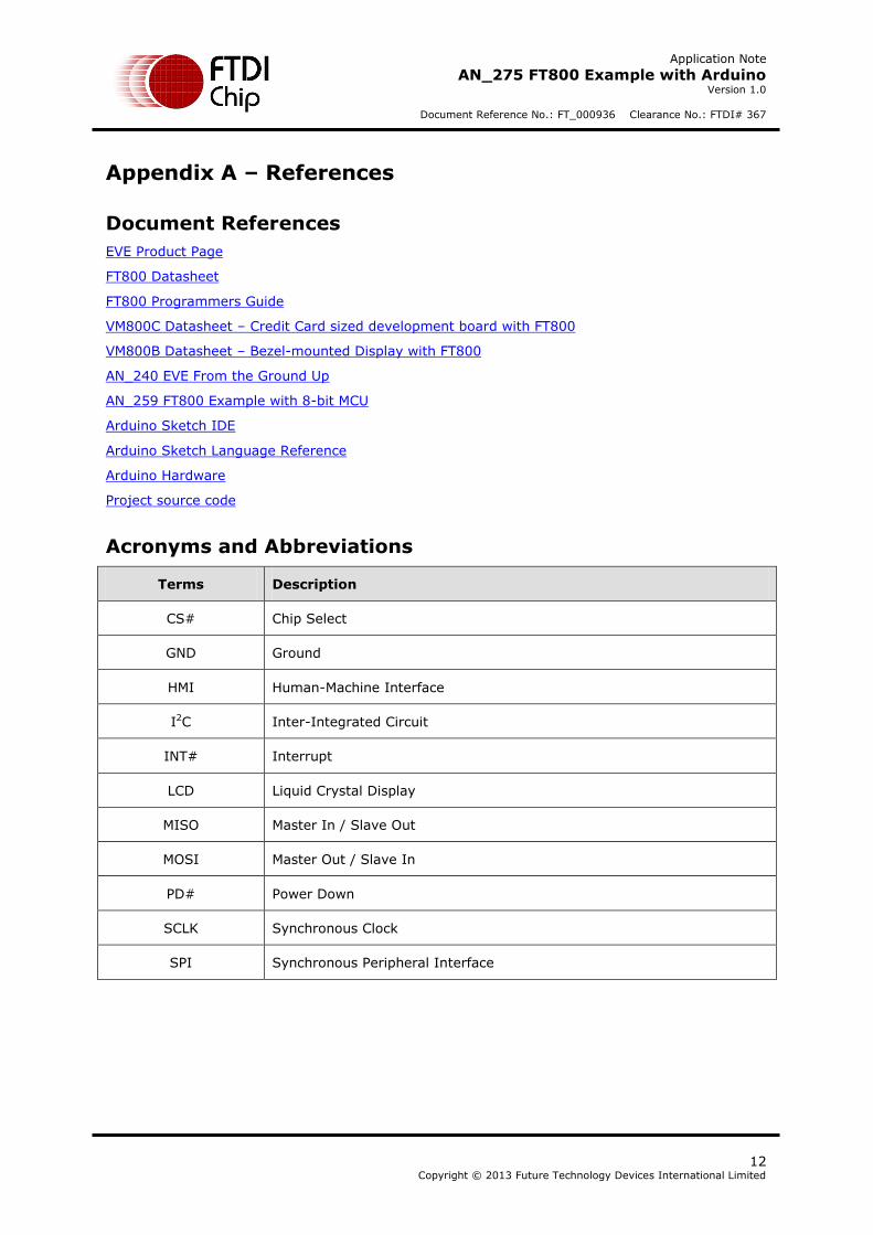
Appendix A – References
Document References
EVE Product Page
FT800 Datasheet
FT800 Programmers Guide
VM800C Datasheet – Credit Card sized development board with FT800
VM800B Datasheet – Bezel-mounted Display with FT800
AN_240 EVE From the Ground Up
AN_259 FT800 Example with 8-bit MCU
Arduino Sketch IDE
Arduino Sketch Language Reference
Arduino Hardware
Project source code
Acronyms and Abbreviations
Terms Description
CS# Chip Select
GND Ground
HMI Human-Machine Interface
I2C Inter-Integrated Circuit
INT# Interrupt
LCD Liquid Crystal Display
MISO Master In / Slave Out
MOSI Master Out / Slave In
PD# Power Down
SCLK Synchronous Clock
SPI Synchronous Peripheral Interface
Application Note
AN_275 FT800 Example with Arduino Version 1.0
Document Reference No.: FT_000936 Clearance No.: FTDI# 367
13 Copyright © 2013 Future Technology Devices International Limited
Appendix B – List of Tables & Figures
List of Tables
Table 4.1 - Arduino Pin Definitions ........................................................................................ 8
Table 4.2 - VM800P Pin Definitions ........................................................................................ 9
List of Figures
Figure 3.1 - Co-Processor Ring Buffer .................................................................................... 5
Figure 3.2 - Sketch Program Output ...................................................................................... 6
Application Note
AN_275 FT800 Example with Arduino Version 1.0
Document Reference No.: FT_000936 Clearance No.: FTDI# 367
14 Copyright © 2013 Future Technology Devices International Limited
Appendix C – Revision History
Document Title: AN_275 FT800 Example with Arduino
Document Reference No.: FT_000936
Clearance No.: FTDI# 367
Product Page: http://www.ftdichip.com/EVE.htm
Document Feedback: Send Feedback
Revision Changes Date
1.0 Initial Release 2013-11-25