Embed Size (px)
Citation preview
FT001M12C
Freqtime
Time and Frequency Remote
Calibration Terminal
FT-001
User’s Guide
Ver.2.02
Aug. 29, 2012
Freqtime Corporation Ltd.

Freqtime 2
Time and Frequency Remote Calibration Terminal
FT-001

Freqtime 3
Contents
1. Before use
2. Introduction
3. Rated Value and Recommended operating conditions
4. Appearance
5. Setup information
6. Quick start
7. Operation Modes
8. Front panel LED
9. Installing the USB driver and Controller Program
(for Win32bitmachine only)
10. Initial Settings by using Controller Program
Appendix
A-1 Introduction of CGGTTS format
A-2 CGGTTS header
A-3 CGGTTS Data part
A-4 Schedule for CGGTTS format Data
A-5 Install Lantronix software “Device Installer”

Freqtime 4
1. Before use
WARNING
The following precautions are intended to avoid danger of the user's body and life, and
damage and deterioration of the product. It may cause a serious accident or malfunction,
be sure to follow them.
Make sure the current and voltage of AC power source apply the rated of product. Use only
the supplied AC power cord, or it may cause the risk of electric shock or fire.
To avoid electrical shock and to protect the product, ground GND terminal of AC power cord.
Do not input the reference signal which exceeds the specification of the product. It may
cause malfunction.
Do not input other signal or DC voltage to outputs. It may cause malfunction.
Use the product within the range of operating temperature and humidity, or it may cause the
risk of electric shock or fire.
Do not use the product in a place where inflammable gas, explosive gas, or steam are
generated/stored and near them. It may cause the risk of fire.
Do not use the product in a place where corrosive gas is generated or is filled. It may cause
serious damage to the product.
Do not put any metals, inflammable substances, or water in the vent of the product. It may
cause the risk of electric shock, fire, or serious damage to the product.
When smoke, fire, and odor emits from the product, or any abnormalities are noticed, stop
using the product immediately and unplug the power cord. Make sure that there is no risk of
fire around the product, and then contact us or the distributor.
Freqtime Corporation shall not be liable for any other use which is not mentioned herein, and
shall not be liable for technical or editorial errors or omissions contained herein.
The product is intended for use in Japan. When used in a foreign country, be sure to contact
the distributor.
Freqtime 5
2. Introduction
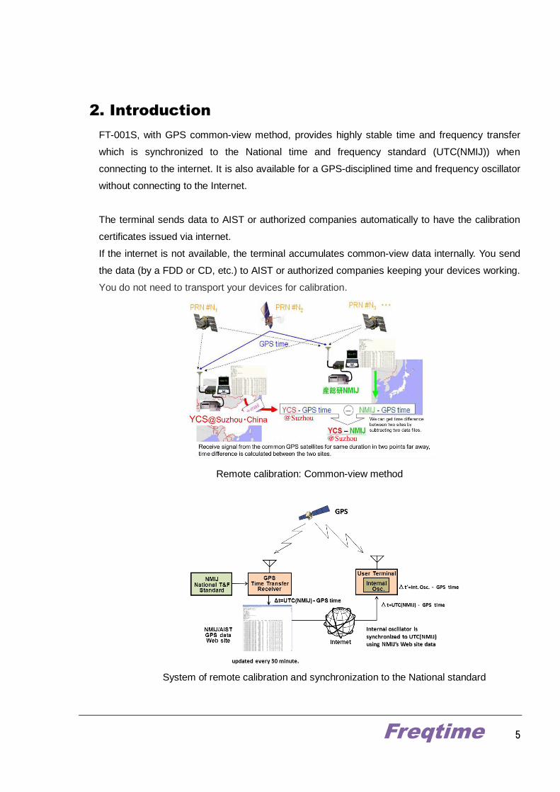
FT-001S, with GPS common-view method, provides highly stable time and frequency transfer
which is synchronized to the National time and frequency standard (UTC(NMIJ)) when
connecting to the internet. It is also available for a GPS-disciplined time and frequency oscillator
without connecting to the Internet.
The terminal sends data to AIST or authorized companies automatically to have the calibration
certificates issued via internet.
If the internet is not available, the terminal accumulates common-view data internally. You send
the data (by a FDD or CD, etc.) to AIST or authorized companies keeping your devices working.
You do not need to transport your devices for calibration.
Remote calibration: Common-view method
System of remote calibration and synchronization to the National standard

Freqtime 6
3. Specifications and Recommended operating conditions
Specifications of FT-001S, FT-001S/H
Specification
GPS receiver unit
Receiving signal L1(1574.42 MHz), C/A code
Number of receiving channels 50 channels
Sensitivity -160 dBm
Reference signal
Input (for time transfer mode) 1 pps or 10 MHz
Output (for Internal oscillator mode)
10 MHz/1 port +13 dBm± 1 dBm @ 50 Ω
1 pps/1 port
Time and frequency Transfer function
Data exchange format CGGTTS format ( 1 s and 15 s output interval also available)
Synchronization function NMI(J)-DO or GPS-DO
Data transmission protocol HTTP protocol
Internal Oscillator
Standard version TCXO
SSB Phase noise < -80 dBc@10 Hz, < -110 dBc@1 kHz Allan deviation < 2×10
-10@1 s
Option #01 OCXO
SSB Phase noise <-105 dBc@10 Hz, < -135 dBc@1 kHz Allan deviation < 5×10
-11@1 s
Option #02 Double oven type OCXO
SSB Phase noise < -115 dBc@10 Hz, < -135 dBc@1 kHz Allan deviation < 2×10
-12@1 s
Option #03 BVA type OCXO SSB Phase noise < -137 dBc@10 Hz, -145 dBc@1 kHz
Allan deviation < 3×10-13
@1 - 30 s
Option #04 Rubidium Oscillator SSB Phase noise < -130 dBc@10 Hz, < -150 dBc@1 kHz
Allan deviation < 2×10-11
@1 s, 2×10-12
@ 100 s
Option #05 CSAC(Chip Scale Atomic Clock) SSB Phase noise < -78 dBc@10 Hz, < -128 dBc@1 kHz
Allan deviation < 1.5×10⁻¹⁰
@1 s, 1.5×10⁻¹¹
@ 100 s
Data communication Interface
Standard type Ethernet (10/100 BASE-T) and USB
Option #11 Blue tooth (Under development)
Option #12 Zigbee (Under development)
Option #13 RS232C
NTP function Option #31 Precision <1 μs ; Maximum access <50
Distribution amplifier
Option #41 10 MHz 8 ports
Option #42 10 MHz 4 ports
Option #43 1 pps 8 ports
Option #44 1 pps 4 ports
Receiving antenna
Option #51 Small size antenna with 5 m cable
Option #52 Out side mount type
Time display and time code
Option #61 Yyyymmdd hhmmdd (Under development)
Option #62 IRIG-B (Under development)
Synchronization to UTC(NMIJ) *2 Uncertainty < 50 ns (Preliminary value)

Freqtime 7
Frequency transfer *2 < 1 ×10-13
@ 1 day
Dimension 19 inches EIA rack 2U size (88(H) ×430(W)×350(D) mm)
Power supply 100-240 Vac, < 50 W
Operational temperature 0~+50 ℃
Specifications of FT-001A
Specification
GPS receiver unit
Receiving signal L1(1574.42 MHz), C/A code
Number of receiving channels 50 channels
Sensitivity -160 dBm
Reference signal
Input (for time transfer mode) 1 pps or 10 MHz
Output (for Internal oscillator mode)
10 MHz/1 port +13 dBm± 1 dBm @ 50 Ω
1 pps/1 port
Time and frequency Transfer function
Data exchange format CGGTTS format ( 1 s and 15 s output interval also available)
Synchronization function NMI(J)-DO or GPS-DO
Data transmission protocol HTTP protocol
Internal Oscillator
Standard version TCXO SSB Phase noise < -80 dBc@10 Hz, < -110 dBc@1 kHz
Allan deviation < 2×10⁻¹⁰
@1 s
Option #01 OCXO SSB Phase noise <-105 dBc@10 Hz, < -135 dBc@1 kHz
Allan deviation < 5×10-11
@1 s
Option #05 CSAC(Chip Scale Atomic Clock) SSB Phase noise < -78 dBc@10 Hz, < -128 dBc@1 kHz
Allan deviation < 1.5×10⁻¹⁰
@1 s, 1.5×10⁻¹¹
@ 100 s
Data communication Interface
Standard type Ethernet (10/100 BASE-T) and USB
Option #11
Option #12
Option #13 RS232C
Receiving antenna
Option #51 Small size antenna with 5 m cable
Option #52 Out side mount type
Synchronization to UTC(NMIJ) *2 Uncertainty < 50 ns (Preliminary value)
Frequency transfer *2 < 1 ×10-13
@ 1 day
Dimension < 40(H) ×95(W)×140(D) mm)
Power supply 5 Vdc, < 3 W (AC adapter or USB bus power can be used)
Operational temperature and humidity 0~+50 ℃ and 20~70 %
*1: Rated value indicates the value in the recommended operating conditions.
*2: Data transmission depends on the user's network environment, contact us for more information.
Freqtime 8
*3: The performance of time synchronization and frequency comparison depend on the status of GPS reception.
Specifications subject to change without notice.
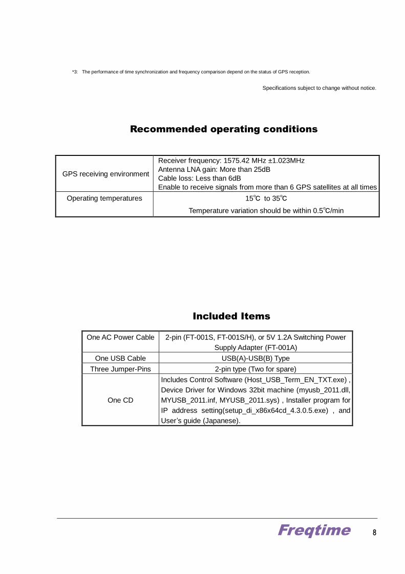
Recommended operating conditions
Included Items
GPS receiving environment
Receiver frequency: 1575.42 MHz ±1.023MHz
Antenna LNA gain: More than 25dB
Cable loss: Less than 6dB
Enable to receive signals from more than 6 GPS satellites at all times
Operating temperatures 15℃ to 35℃
Temperature variation should be within 0.5℃/min
One AC Power Cable 2-pin (FT-001S, FT-001S/H), or 5V 1.2A Switching Power
Supply Adapter (FT-001A)
One USB Cable USB(A)-USB(B) Type
Three Jumper-Pins 2-pin type (Two for spare)
One CD
Includes Control Software (Host_USB_Term_EN_TXT.exe) ,
Device Driver for Windows 32bit machine (myusb_2011.dll,
MYUSB_2011.inf, MYUSB_2011.sys) , Installer program for
IP address setting(setup_di_x86x64cd_4.3.0.5.exe) , and
User’s guide (Japanese).
Freqtime 9
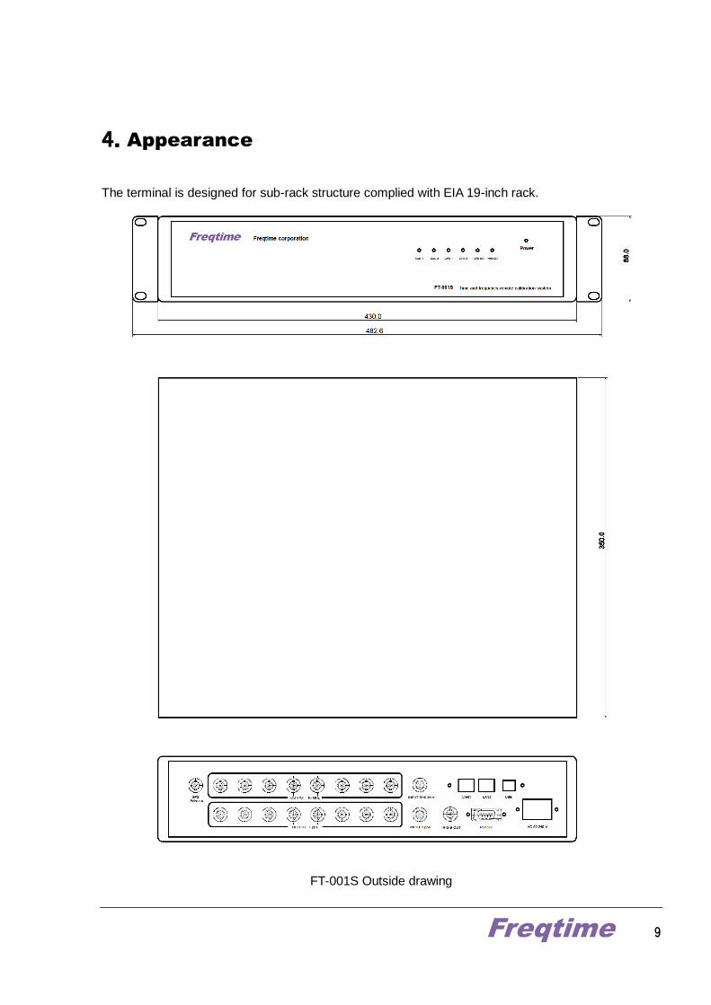
4.Appearance
The terminal is designed for sub-rack structure complied with EIA 19-inch rack.
FT-001S Outside drawing

Freqtime 10
FT-001S/H Half size version Outside drawing
Freqtime 11
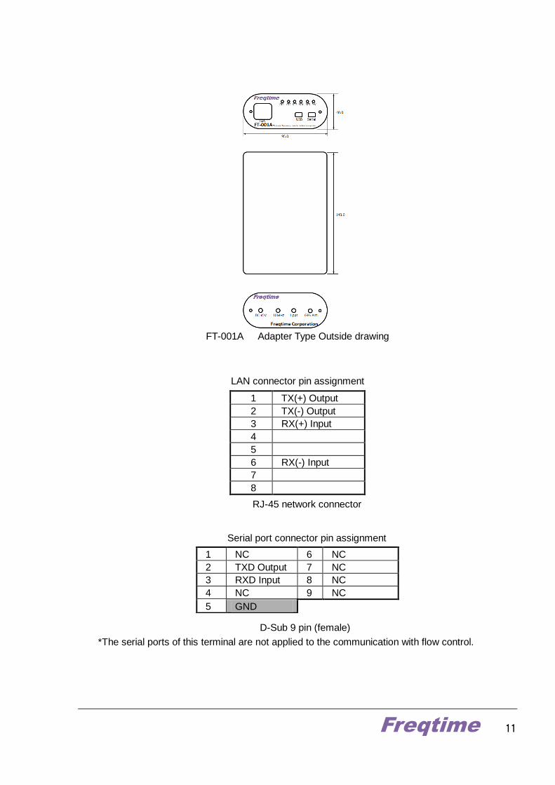
FT-001A Adapter Type Outside drawing
LAN connector pin assignment
RJ-45 network connector
Serial port connector pin assignment
D-Sub 9 pin (female)
*The serial ports of this terminal are not applied to the communication with flow control.
1 TX(+) Output
2 TX(-) Output
3 RX(+) Input
4
5
6 RX(-) Input
7
8
1 NC 6 NC
2 TXD Output 7 NC
3 RXD Input 8 NC
4 NC 9 NC
5 GND
Freqtime 12
5.Notification for Settings
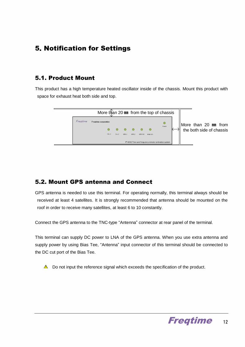
5.1. Product Mount
This product has a high temperature heated oscillator inside of the chassis. Mount this product with
space for exhaust heat both side and top.
5.2. Mount GPS antenna and Connect
GPS antenna is needed to use this terminal. For operating normally, this terminal always should be
received at least 4 satellites. It is strongly recommended that antenna should be mounted on the
roof in order to receive many satellites, at least 6 to 10 constantly.
Connect the GPS antenna to the TNC-type “Antenna” connector at rear panel of the terminal.
This terminal can supply DC power to LNA of the GPS antenna. When you use extra antenna and
supply power by using Bias Tee, “Antenna” input connector of this terminal should be connected to
the DC cut port of the Bias Tee.
Do not input the reference signal which exceeds the specification of the product.
More than 20 ㎜ from the top of chassis
More than 20 ㎜ from
the both side of chassis

Freqtime 13
5.3. Network Connection
To use this terminal in NMIJ-DO mode, Internet connection should be needed. Connect “LAN” port of the
rear panel to it and establish connection to NMIJ server. For more details, see ”10. Initial Settings by
using Controller Program” .
5.4. USB Connection
The setting of this terminal and/or data logging is made via USB port or optional serial port on the rear
panel. For more details, see ”9. Installing the USB driver and Controller Program ( for
Win32bitmachine only)”.
5.5. Power-on
This terminal doesn’t have any power switch to prevent the power-off from miss-operation while it’s
working. Connect AC cable to the terminal and it starts to work.
5.6. Initial Setting
Information about running mode of this terminal and how to set are described in chapter 10 ”Initial
Settings by using Controller Program” of this document, in detail.
Freqtime 14
6. Quick start
Things to prepare
PC (32-bit Windows)
USB cable (supplied)
Power cord (FT-001S, FT-001S/H), (supplied)
or 5V 1.2A Switching Power Supply Adapter (FT-001A) (supplied)
Control software “FT-USB_Term”
1. Install control software “FT-USB_Term” in the PC beforehand.
( How to install FT-USB_Term, see “ 9. Configuration with USB port ”. )
2. Plug the power cord into the terminal, and then turn on the power.
3. Connect the PC and the terminal with the USB cable to let the terminal detect
the PC.
4. Start up FT-USB_Term.
5. Click Connect button.
At first, initialize the terminal for data acquisition.
6. Set up “Server Settings”.
・To set NMIJ-DO mode, enter the referring URL to the text box of “GET Address” and press
the “Set” buton.
・To upload the calibrated data automatically to NMIJ, enter the URL issued from NMI to the
text box of “GET Address” and press the “Set” buton.
・To access the Internet via a proxy, enter proxy name, user account, etc… and press “Set”
button. After that, press “Enable” button of the text box of “Use Proxy Server”. When you do
not use a proxy server, you can leave this field blank.
7. Set up “Discipline Mode Settings”.
・To start in NMI-DO mode, click NMI-DO.
・To start in GPS-DO mode, click GPS-DO.
・If you do not select either, the terminal will select GPS-DO mode automatically.

Freqtime 15
8. Set up “Position Mode Settings”.
・When you know the antenna coordinates, enter the values of coordinates at Fix mode, and
then click Set.
・When you do not know the antenna coordinates, select Survey-In mode.
You can set the time for calculating the coordinates and accuracy of the coordinates. When
the terminal achieves either of time or accuracy, they will be fixed and the terminal will be set
to Fix mode automatically.
However, if the values you set are too small, or the coordinates do not converge during the
time for calculating the coordinates, please note that the terminal will accept the optimum
coordinates obtained during the searching time, and will start to measure with them.
9. Set up “Data settings”.
・Input the values of internal delay, cable delay and reference delay.
・To send the data for calibration to NMI automatically, click Start at Auto Data Sending.
10. Set up “Saving the settings”.
・To save the settings to the internal SD card of the terminal, click Save Settings. The
terminal will start with the previous settings from the next you turn on the power.
The terminal outputs data format complied with CGGTTS Format in every second. Although you can
monitor the data immediately, the 1-second data is not saved in the terminal.
If you need to store the 1-second data, check Log at Data logging, and then the data will be saved in
PC by the control software. 1-second data will be saved in C: drive as a file named “Receive.txt”.
For more details on how to use the control software, see chapter 10.
Freqtime 16
7. Operation Modes
The terminal has the following operating modes. Select the mode before operation.
7.1. Time Comparison Mode
Time Comparison Mode is consisted of two modes, internal sync mode and external sync mode.
Internal sync mode can be further classified into two modes; NMI-DO mode and GPS-DO mode.
NMI-DO mode
This mode lets the internal oscillator synchronize to NMI standard by downloading CGGTTS
data from NMI via the Internet.
For example, if you set to download CGGTTS data from AIST/NMIJ, the terminal executes
phase synchronization to UTC(NMIJ). To operate the terminal in this mode, internet
connection and various settings are required.
GPS-DO mode
This mode lets the internal oscillator synchronize to GPS system clock. Any particular
settings are not required to operate the terminal in this mode. The terminal will be set to this
mode from NMI-DO mode automatically when the terminal is not connected to the Internet
for a while. To operate the terminal in this mode, connect a GPS antenna, and turn on the
power of the terminal.
Time comparison mode by the external oscillator
This mode lets the external oscillator execute time comparison by inputting signals to the
terminal. To operate the terminal in this mode, replace the jumper pins on built-in circuit
board. For more information, please contact to us ([email protected]).
7.2. Coordinates Mode
The synchronization control of the reference signal using GPS, the coordinates of the receiver
antenna will be an important factor.
The terminal has three modes, NAV Mode, FIX Mode, and Survey-in Mode.
Freqtime 17
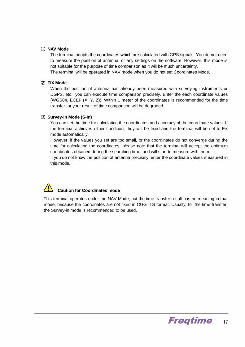
① NAV Mode
The terminal adopts the coordinates which are calculated with GPS signals. You do not need
to measure the position of antenna, or any settings on the software. However, this mode is
not suitable for the purpose of time comparison as it will be much uncertainty.
The terminal will be operated in NAV mode when you do not set Coordinates Mode.
② FIX Mode
When the position of antenna has already been measured with surveying instruments or
DGPS, etc., you can execute time comparison precisely. Enter the each coordinate values
(WGS84, ECEF (X, Y, Z)). Within 1 meter of the coordinates is recommended for the time
transfer, or your result of time comparison will be degraded.
③ Survey-In Mode (S-In)
You can set the time for calculating the coordinates and accuracy of the coordinate values. If
the terminal achieves either condition, they will be fixed and the terminal will be set to Fix
mode automatically.
However, if the values you set are too small, or the coordinates do not converge during the
time for calculating the coordinates, please note that the terminal will accept the optimum
coordinates obtained during the searching time, and will start to measure with them.
If you do not know the position of antenna precisely, enter the coordinate values measured in
this mode.
Caution for Coordinates mode
This terminal operates under the NAV Mode, but the time transfer result has no meaning in that
mode, because the coordinates are not fixed in CGGTTS format. Usually, for the time transfer,
the Survey-in mode is recommended to be used.
Freqtime 18
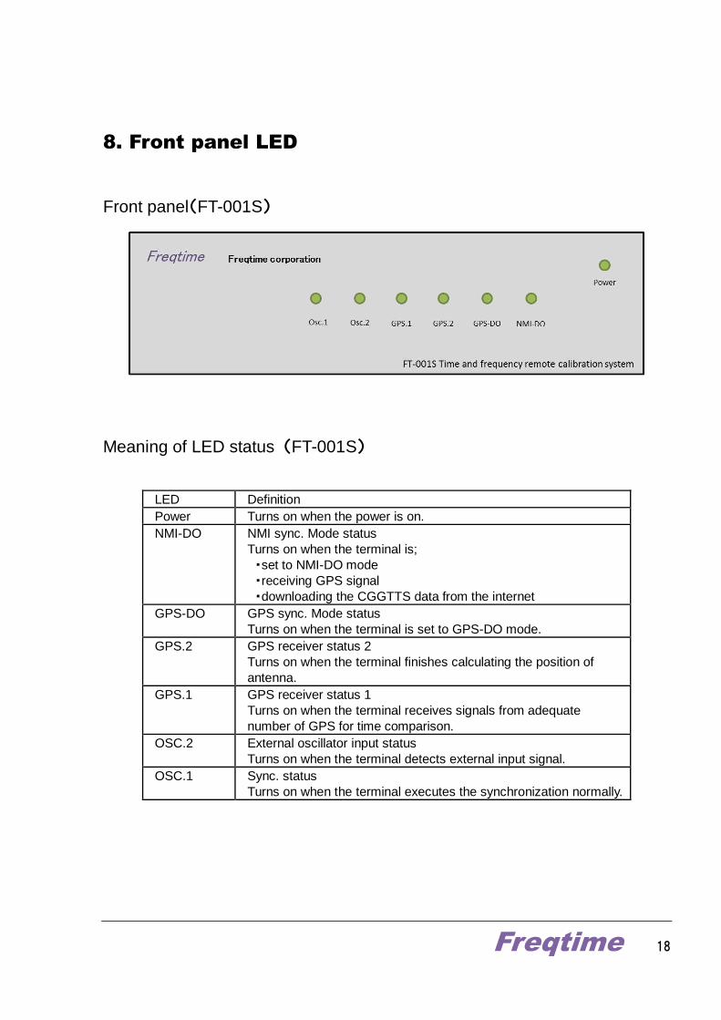
8. Front panel LED
Front panel(FT-001S)
Meaning of LED status (FT-001S)
LED Definition
Power Turns on when the power is on.
NMI-DO NMI sync. Mode status
Turns on when the terminal is;
・set to NMI-DO mode
・receiving GPS signal
・downloading the CGGTTS data from the internet
GPS-DO GPS sync. Mode status
Turns on when the terminal is set to GPS-DO mode.
GPS.2 GPS receiver status 2
Turns on when the terminal finishes calculating the position of
antenna.
GPS.1 GPS receiver status 1
Turns on when the terminal receives signals from adequate
number of GPS for time comparison.
OSC.2 External oscillator input status
Turns on when the terminal detects external input signal.
OSC.1 Sync. status
Turns on when the terminal executes the synchronization normally.
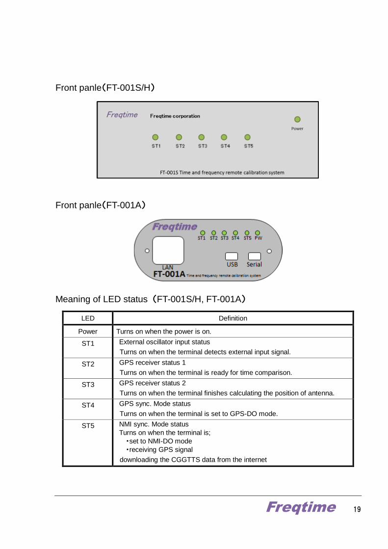
Freqtime 19
Front panle(FT-001S/H)
Front panle(FT-001A)
Meaning of LED status (FT-001S/H, FT-001A)
LED Definition
Power Turns on when the power is on.
ST1 External oscillator input status
Turns on when the terminal detects external input signal.
ST2 GPS receiver status 1
Turns on when the terminal is ready for time comparison.
ST3 GPS receiver status 2
Turns on when the terminal finishes calculating the position of antenna.
ST4 GPS sync. Mode status
Turns on when the terminal is set to GPS-DO mode.
ST5 NMI sync. Mode status
Turns on when the terminal is;
・set to NMI-DO mode
・receiving GPS signal
downloading the CGGTTS data from the internet
Freqtime 20
9. Configuration with USB port
You can operate the terminal, confirm the status of configuration, and retrieve log information by
connecting a PC installed the control software to a USB port on the rear of the terminal.
9.1 Installing the USB driver and FT-USB_Term sortware
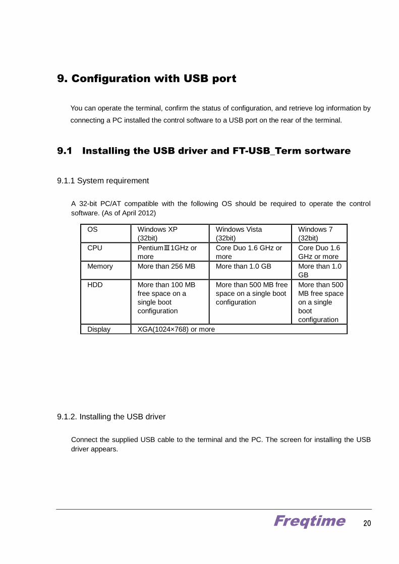
9.1.1 System requirement
A 32-bit PC/AT compatible with the following OS should be required to operate the control
software. (As of April 2012)
9.1.2. Installing the USB driver
Connect the supplied USB cable to the terminal and the PC. The screen for installing the USB
driver appears.
OS Windows XP
(32bit)
Windows Vista
(32bit)
Windows 7
(32bit)
CPU PentiumⅢ1GHz or
more
Core Duo 1.6 GHz or
more
Core Duo 1.6
GHz or more
Memory More than 256 MB More than 1.0 GB More than 1.0
GB
HDD More than 100 MB
free space on a
single boot
configuration
More than 500 MB free
space on a single boot
configuration
More than 500
MB free space
on a single
boot
configuration
Display XGA(1024×768) or more
Freqtime 21
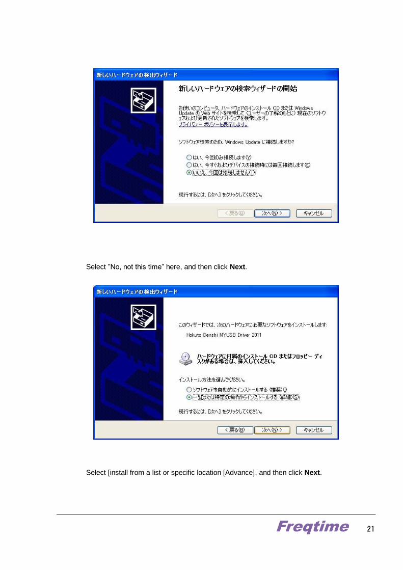
Select ”No, not this time” here, and then click Next.
Select [install from a list or specific location [Advance], and then click Next.
Freqtime 22
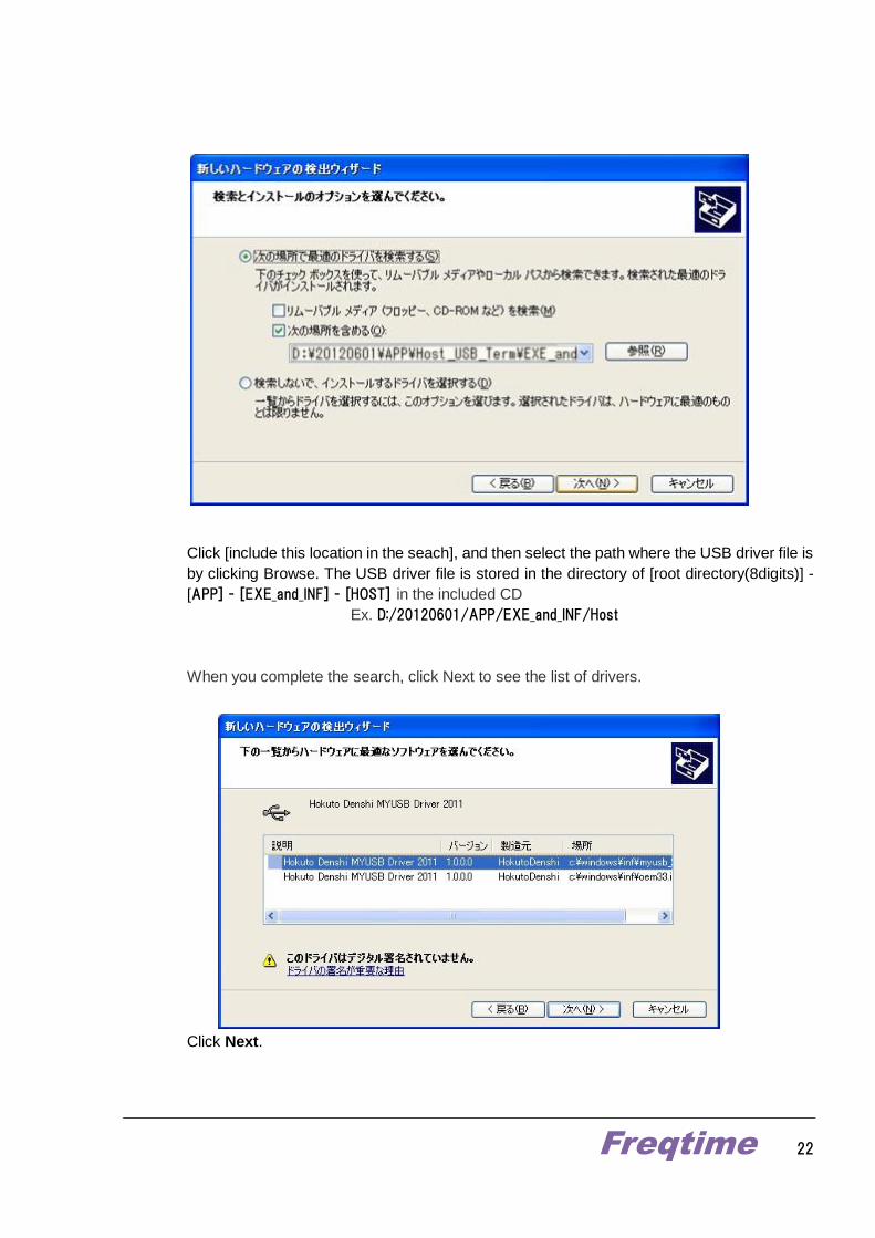
Click [include this location in the seach], and then select the path where the USB driver file is
by clicking Browse. The USB driver file is stored in the directory of [root directory(8digits)] -
[APP] - [EXE_and_INF] - [HOST] in the included CD
Ex. D:/20120601/APP/EXE_and_INF/Host
When you complete the search, click Next to see the list of drivers.
Click Next.
Freqtime 23
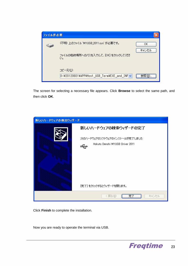
The screen for selecting a necessary file appears. Click Browse to select the same path, and
then click OK.
Click Finish to complete the installation.
Now you are ready to operate the terminal via USB.
Freqtime 24
9.1.3 Starting up the control software “Host_USB_Term_EN_TXT.exe”
The control software is stored in the directory of [root directory (8digits)] - [APP] -
[Host_USB_Term] - [EXE_and_INF] in the included CD
Ex. D:/20120601/APP/Host_USB_Term/EXE_and_INF/Host_USB_Term_EN_TXT.exe
This control software does not need to be installed to your system, because it can work single
software unit. Copy it to your specified directory for your convenience.
The software will easily star up by double clicking.
Freqtime 25
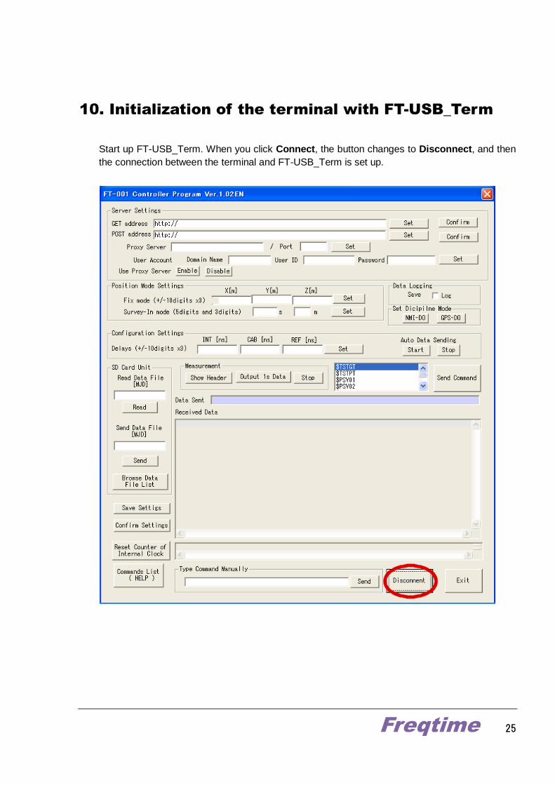
10. Initialization of the terminal with FT-USB_Term
Start up FT-USB_Term. When you click Connect, the button changes to Disconnect, and then
the connection between the terminal and FT-USB_Term is set up.
Freqtime 26
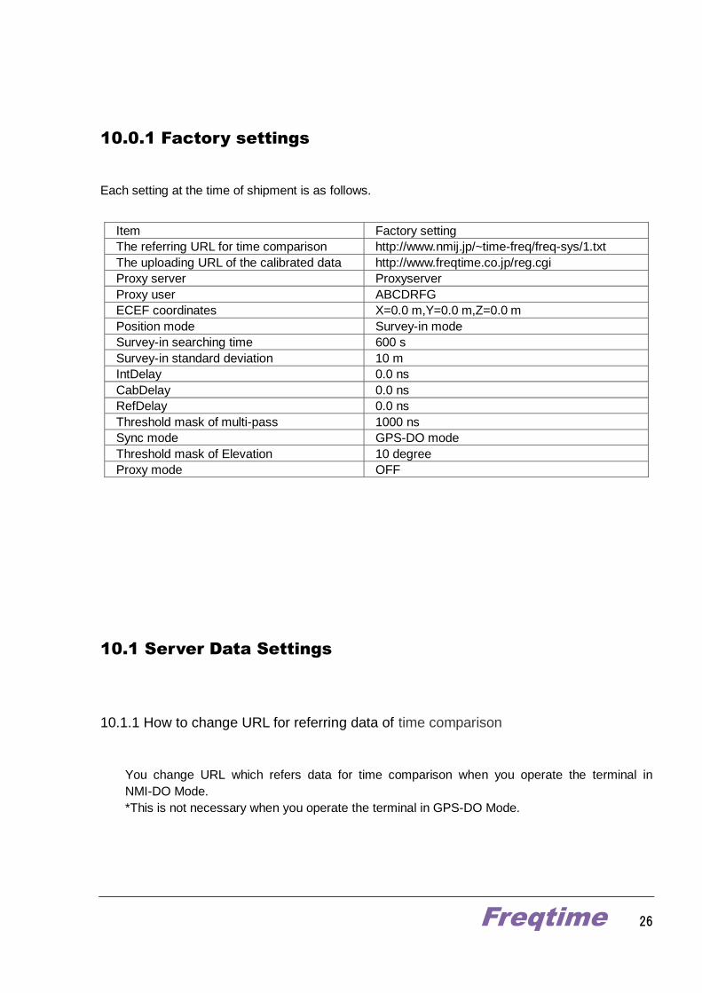
10.0.1 Factory settings
Each setting at the time of shipment is as follows.
Item Factory setting
The referring URL for time comparison http://www.nmij.jp/~time-freq/freq-sys/1.txt
The uploading URL of the calibrated data http://www.freqtime.co.jp/reg.cgi
Proxy server Proxyserver
Proxy user ABCDRFG
ECEF coordinates X=0.0 m,Y=0.0 m,Z=0.0 m
Position mode Survey-in mode
Survey-in searching time 600 s
Survey-in standard deviation 10 m
IntDelay 0.0 ns
CabDelay 0.0 ns
RefDelay 0.0 ns
Threshold mask of multi-pass 1000 ns
Sync mode GPS-DO mode
Threshold mask of Elevation 10 degree
Proxy mode OFF
10.1 Server Data Settings
10.1.1 How to change URL for referring data of time comparison
You change URL which refers data for time comparison when you operate the terminal in
NMI-DO Mode.
*This is not necessary when you operate the terminal in GPS-DO Mode.

Freqtime 27
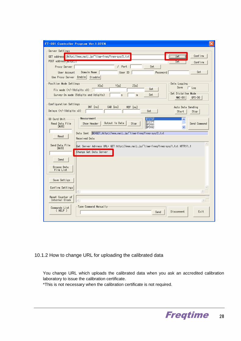
Click Confirm on the right of GET address field while the connection has been set up, and then
you can confirm the referring URL that is currently configured.
To change the referring URL, enter another URL to GET address field, and then click Set.
The terminal will return the message of ‘Change Get Data Server’.
Freqtime 28
10.1.2 How to change URL for uploading the calibrated data
You change URL which uploads the calibrated data when you ask an accredited calibration
laboratory to issue the calibration certificate.
*This is not necessary when the calibration certificate is not required.
Freqtime 29
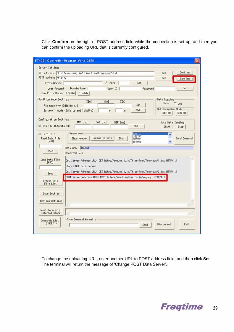
Click Confirm on the right of POST address field while the connection is set up, and then you
can confirm the uploading URL that is currently configured.
To change the uploading URL, enter another URL to POST address field, and then click Set.
The terminal will return the message of ‘Change POST Data Server’.
Freqtime 30
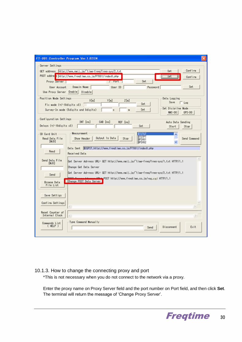
10.1.3. How to change the connecting proxy and port
*This is not necessary when you do not connect to the network via a proxy.
Enter the proxy name on Proxy Server field and the port number on Port field, and then click Set.
The terminal will return the message of ‘Change Proxy Server’.

Freqtime 31
10.1.4. How to change proxy user
* This is not necessary when you do not connect to the network via a proxy.
This terminal is compatible with Basic Authentication to the proxy server.
When you need Basic Authentication, set up a user account. You can enter each field of ‘Domain
name’, ‘User ID’, and ‘Password’. If a domain name is not necessary, you can leave this field
blank.
Enter the appropriate user account, and then click Set. The terminal will return the message of
‘Change Proxy User’.
Freqtime 32
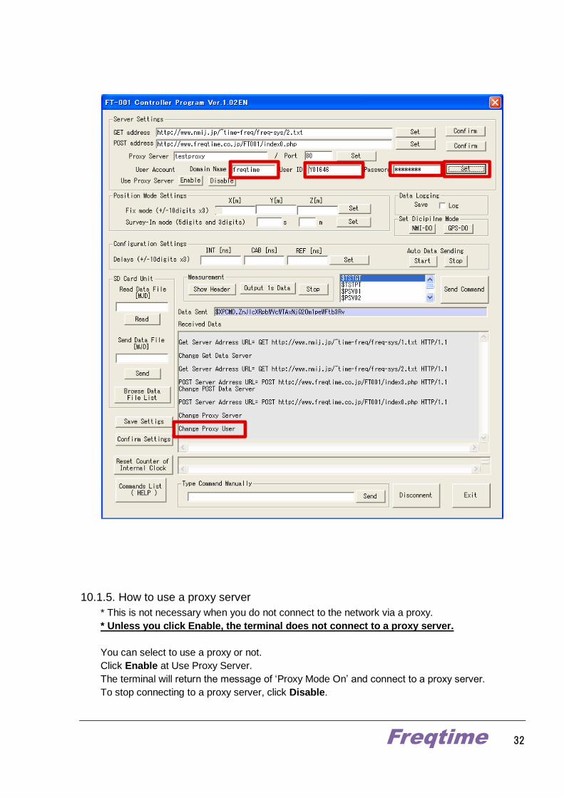
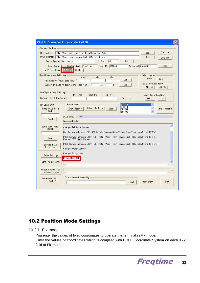
10.1.5. How to use a proxy server
* This is not necessary when you do not connect to the network via a proxy.
* Unless you click Enable, the terminal does not connect to a proxy server.
You can select to use a proxy or not.
Click Enable at Use Proxy Server.
The terminal will return the message of ‘Proxy Mode On’ and connect to a proxy server.
To stop connecting to a proxy server, click Disable.
Freqtime 33
10.2 Position Mode Settings
10.2.1. Fix mode
You enter the values of fixed coordinates to operate the terminal in Fix mode.
Enter the values of coordinates which is complied with ECEF Coordinate System on each XYZ
field at Fix mode.
Freqtime 34
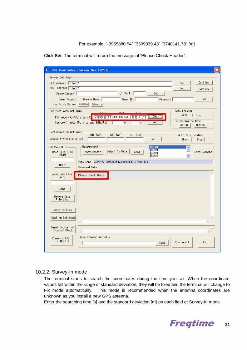
For example: “-3955880.54” “3309039.43” “3740141.78” [m]
Click Set. The terminal will return the message of ‘Please Check Header’.
10.2.2. Survey-In mode
The terminal starts to search the coordinates during the time you set. When the coordinate
values fall within the range of standard deviation, they will be fixed and the terminal will change to
Fix mode automatically. This mode is recommended when the antenna coordinates are
unknown as you install a new GPS antenna.
Enter the searching time [s] and the standard deviation [m] on each field at Survey-In mode.

Freqtime 35
For example: “86400” [s] “5” [m]
Click Set. The terminal will return the message of ‘Change Survey-In MODE’.
10.3. Data Logging
You can save the log output from the terminal. Check Log at Save.
“Receive.txt” will be created in C: drive in the PC, and the log will be written to it.
When you stop data logging, uncheck Log.
*When you see the “Receive.txt” file, please uncheck Log first and open it.
Freqtime 36
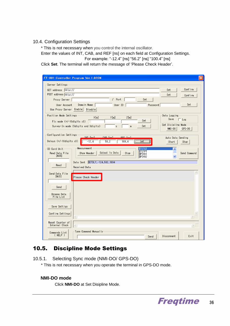
10.4. Configuration Settings
* This is not necessary when you control the internal oscillator.
Enter the values of INT, CAB, and REF [ns] on each field at Configuration Settings.
For example: “-12.4” [ns] “56.2” [ns] “100.4” [ns]
Click Set. The terminal will return the message of ‘Please Check Header’.
10.5. Discipline Mode Settings
10.5.1. Selecting Sync mode (NMI-DO/ GPS-DO)
* This is not necessary when you operate the terminal in GPS-DO mode.
NMI-DO mode
Click NMI-DO at Set Disipline Mode.

Freqtime 37
The terminal will return the message of ‘START GET DATA’.
Now the terminal starts to retrieve data according to CGGTTS format and you operate
the terminal in NMI-DO mode.
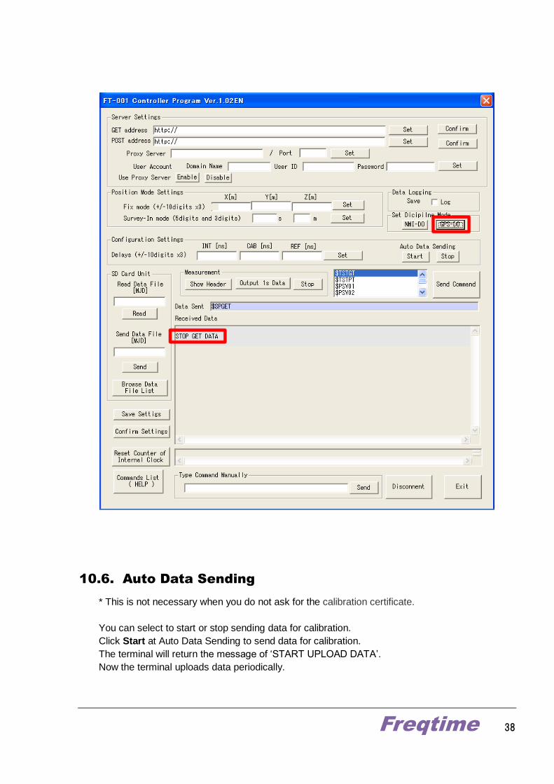
GPS-DO mode
Click GPS-DO at Set Disipline Mode.
The terminal will return the message of ‘STOP GET DATA’.
Now the terminal stops retrieving data, and you operate the terminal in GPS-DO mode.
Freqtime 38
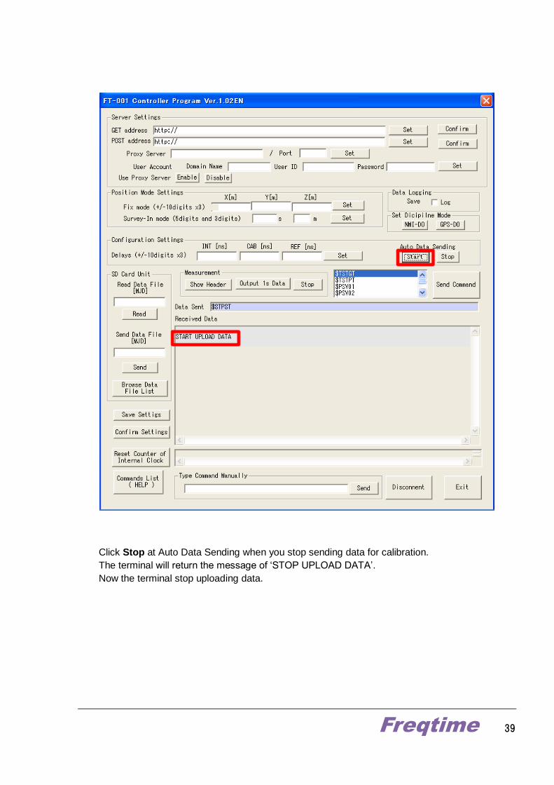
10.6. Auto Data Sending
* This is not necessary when you do not ask for the calibration certificate.
You can select to start or stop sending data for calibration.
Click Start at Auto Data Sending to send data for calibration.
The terminal will return the message of ‘START UPLOAD DATA’.
Now the terminal uploads data periodically.
Freqtime 39
Click Stop at Auto Data Sending when you stop sending data for calibration.
The terminal will return the message of ‘STOP UPLOAD DATA’.
Now the terminal stop uploading data.

Freqtime 40
10.7. Measurement
You can monitor the header of CGGTTS format and the result of time comparison in every
second complied with the format.
10.7.1. Checking CGGTTS Header
Click Show Header at Measurement to check the header.
The terminal will return the information of current header.

Freqtime 41
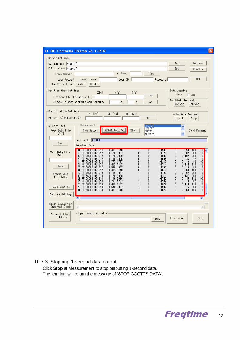
10.7.2. 1-second Data output
Click Output 1s Data at Measurement to start outputting 1-second data.
The terminal will return the result of time comparison in every second.
Freqtime 42
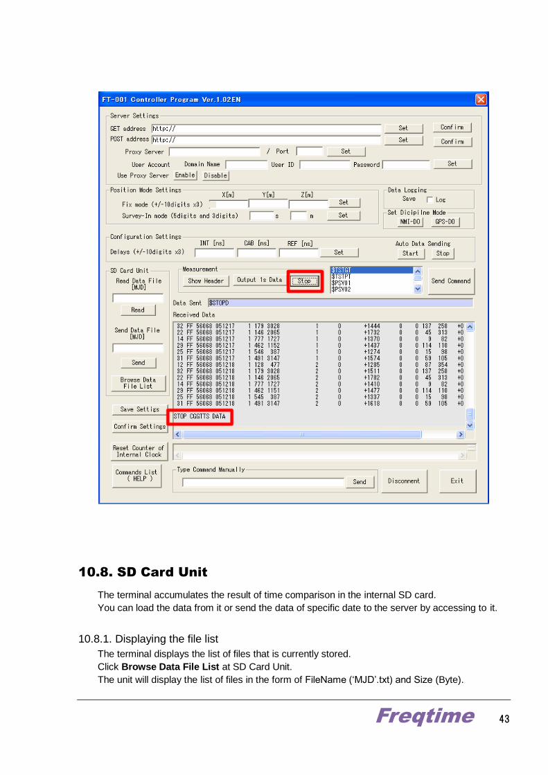
10.7.3. Stopping 1-second data output
Click Stop at Measurement to stop outputting 1-second data.
The terminal will return the message of ‘STOP CGGTTS DATA’.
Freqtime 43
10.8. SD Card Unit
The terminal accumulates the result of time comparison in the internal SD card.
You can load the data from it or send the data of specific date to the server by accessing to it.
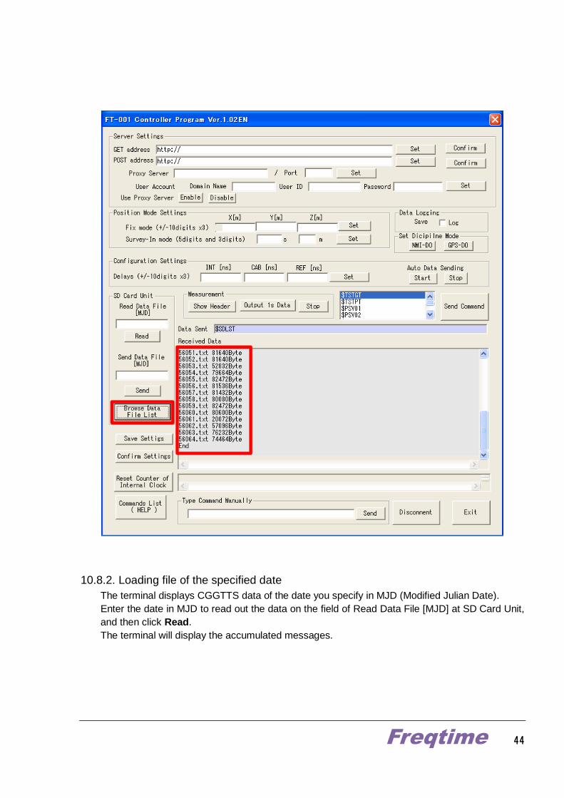
10.8.1. Displaying the file list
The terminal displays the list of files that is currently stored.
Click Browse Data File List at SD Card Unit.
The unit will display the list of files in the form of FileName (‘MJD’.txt) and Size (Byte).
Freqtime 44
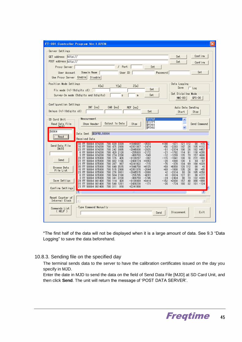
10.8.2. Loading file of the specified date
The terminal displays CGGTTS data of the date you specify in MJD (Modified Julian Date).
Enter the date in MJD to read out the data on the field of Read Data File [MJD] at SD Card Unit,
and then click Read.
The terminal will display the accumulated messages.
Freqtime 45
*The first half of the data will not be displayed when it is a large amount of data. See 9.3 “Data
Logging” to save the data beforehand.
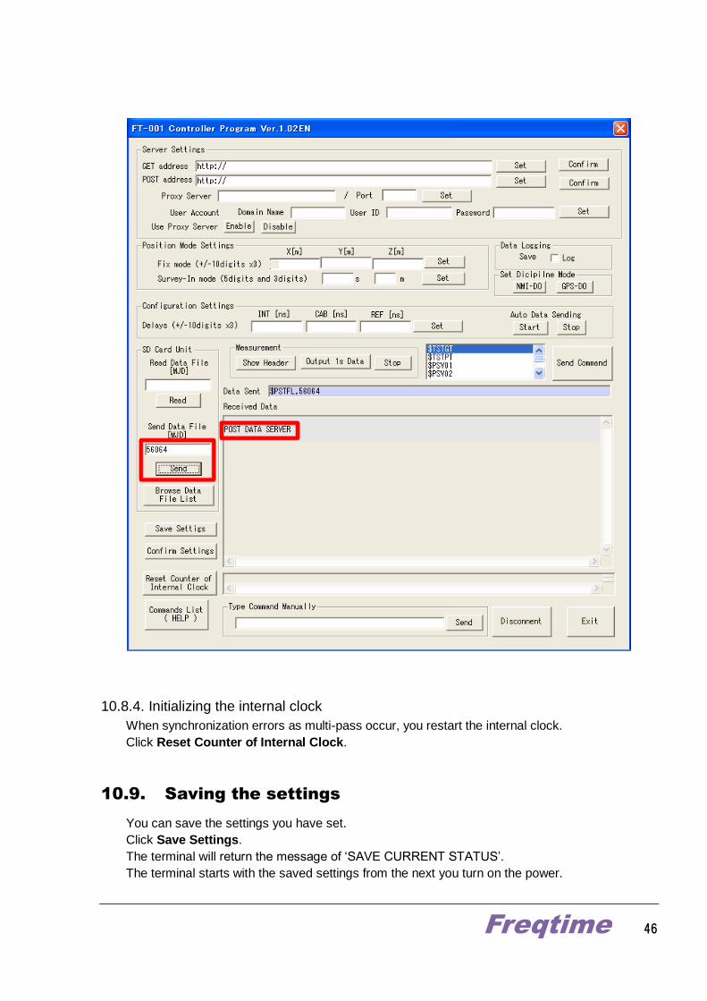
10.8.3. Sending file on the specified day
The terminal sends data to the server to have the calibration certificates issued on the day you
specify in MJD.
Enter the date in MJD to send the data on the field of Send Data File [MJD] at SD Card Unit, and
then click Send. The unit will return the message of ‘POST DATA SERVER’.
Freqtime 46
10.8.4. Initializing the internal clock
When synchronization errors as multi-pass occur, you restart the internal clock.
Click Reset Counter of Internal Clock.
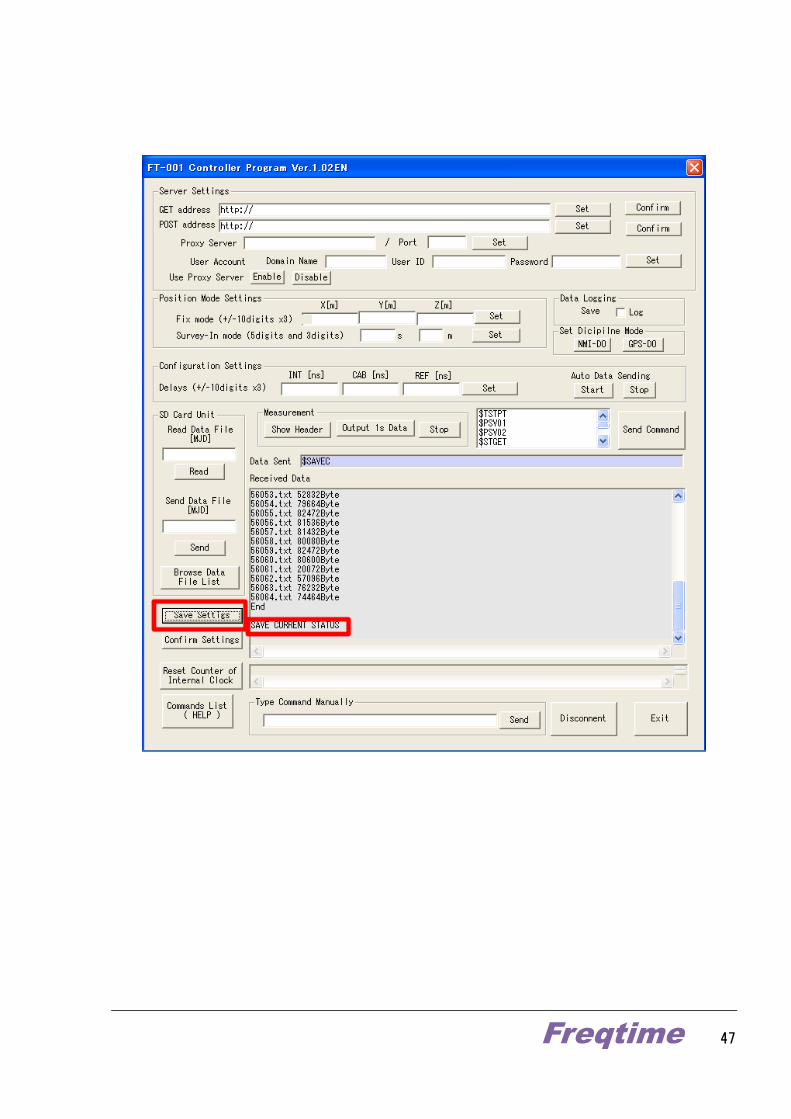
10.9. Saving the settings
You can save the settings you have set.
Click Save Settings.
The terminal will return the message of ‘SAVE CURRENT STATUS’.
The terminal starts with the saved settings from the next you turn on the power.
Freqtime 47
Freqtime 48
10.10. Setting IP address
The terminal is set to obtain IP address automatically via DHCP by default.
To change IP address, the followings are required;
・PC for setting
(Win32 OS which is installed “DeviceInstaller” software
manufactured by Lantronix)
・DHCP
・Network hub
*To install DeviceInstaller, see Appendix A-4.
There are two situations when IP address should be changed. One is to change to fix a new
IP address “from the mode of default settings or of automatically assigned IP address”.
Another is to do “from the mode of already fixed your IP address”.
1. How to fix your IP address from the mode of default settings or of automatically assigned IP address
The terminal is set to obtain IP address automatically via DHCP by default. You can change
the configuration to static IP address as follows.
Connect the hub to DHCP, and then connect the terminal already powered up to the hub.
DHCP will assign IP address to the terminal.
Then connect the PC for setting to the same DHCP to obtain the same IP address as the
terminal.
Next, click Start of Windows on the PC for setting and select “All Programs”
→“Lantronix”→”DeviceInstaller4.3”→”DeviceInstaller” to start the program.

Freqtime 49
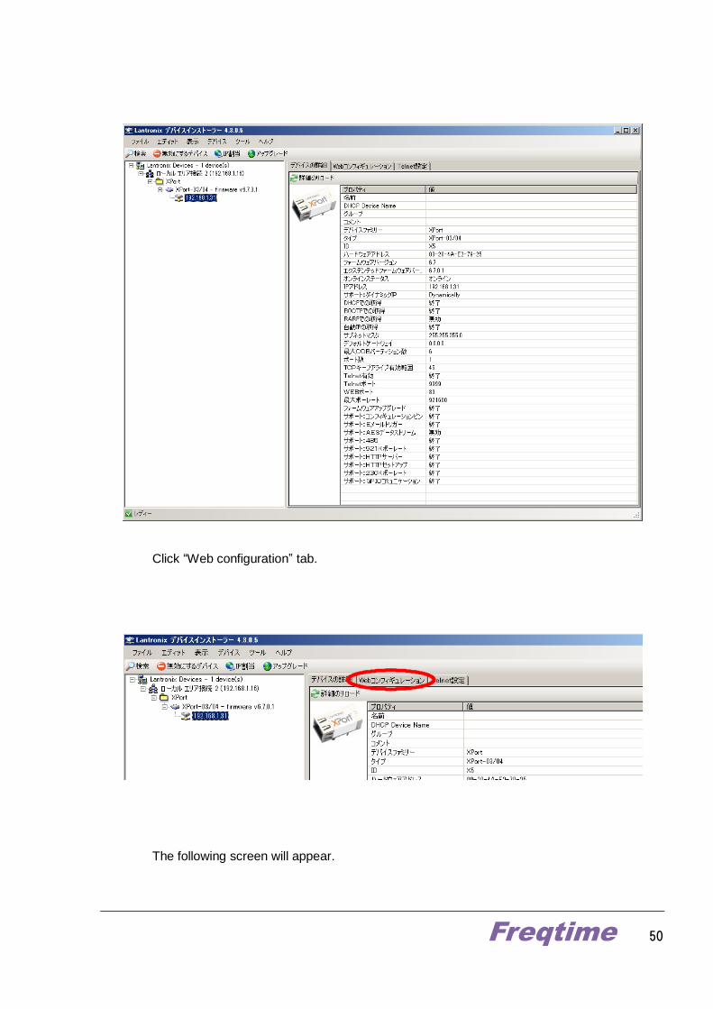
You can find the device named “Xport”.
Click Xport to select IP address.
You can see the list of current settings on the right side of the screen of DeviceInstaller.
Freqtime 50
Click “Web configuration” tab.
The following screen will appear.

Freqtime 51
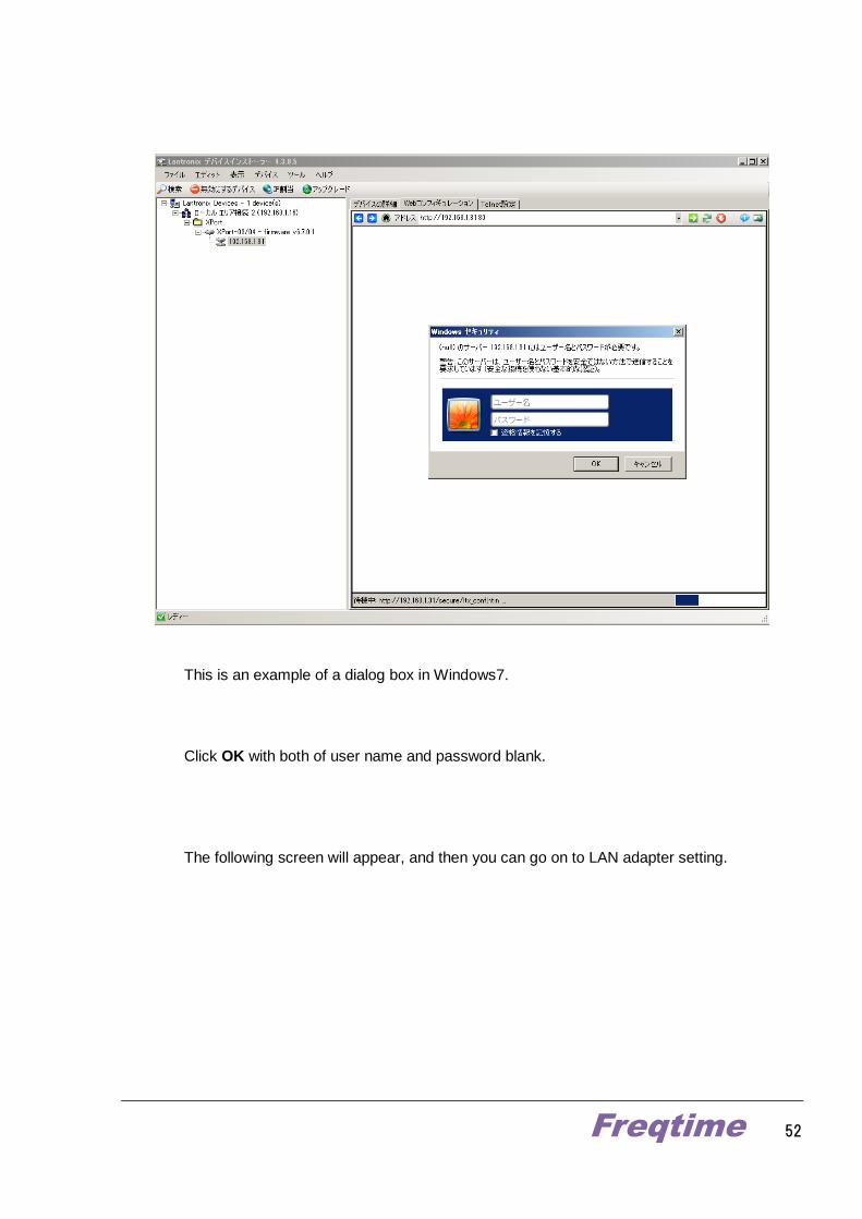
On this screen, click the arrow on the right of the address bar.
A dialog box asking for user name and password will appear.
Freqtime 52
This is an example of a dialog box in Windows7.
Click OK with both of user name and password blank.
The following screen will appear, and then you can go on to LAN adapter setting.
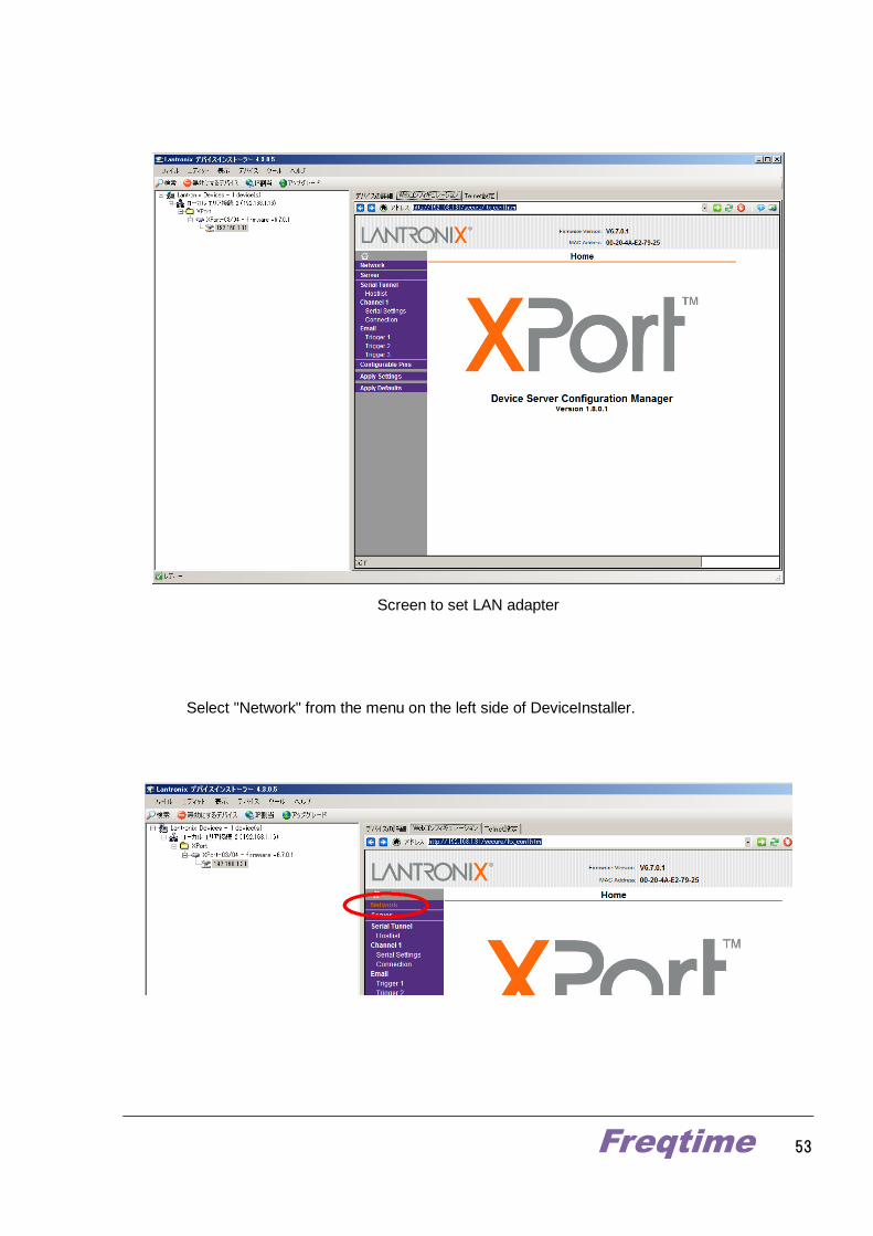
Freqtime 53
Screen to set LAN adapter
Select "Network" from the menu on the left side of DeviceInstaller.
Freqtime 54
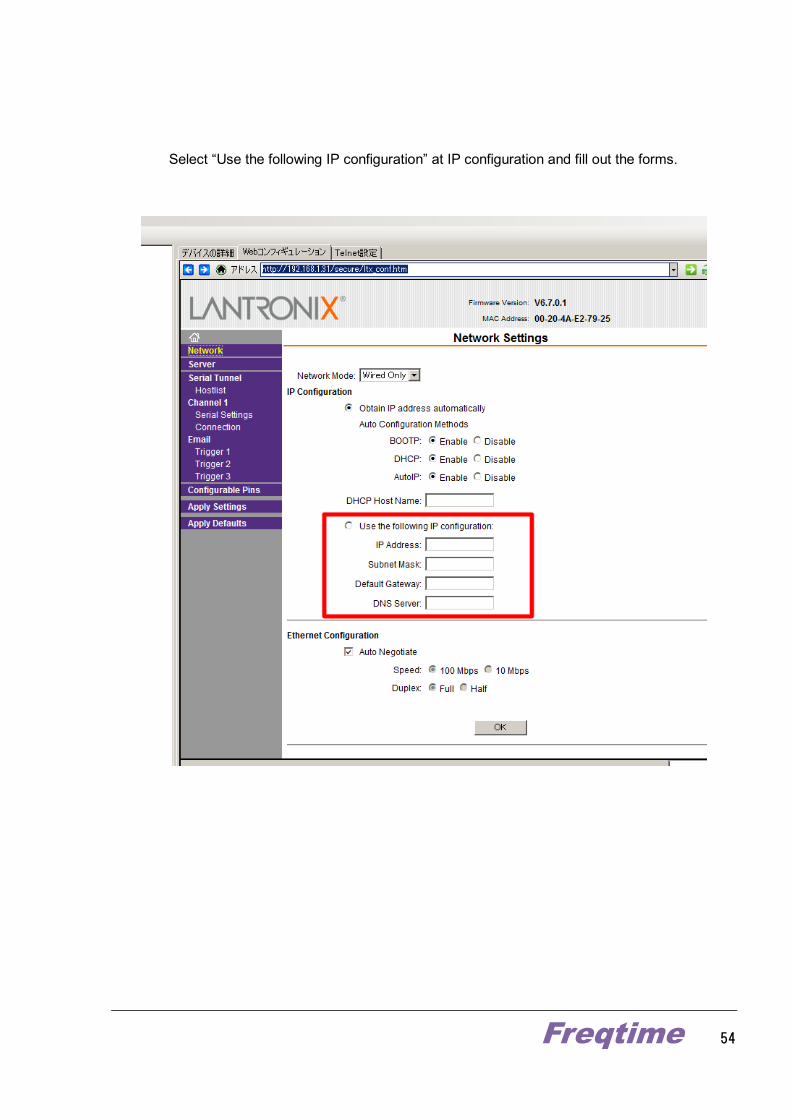
Select “Use the following IP configuration” at IP configuration and fill out the forms.
Freqtime 55
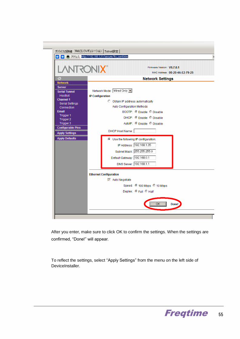
After you enter, make sure to click OK to confirm the settings. When the settings are
confirmed, “Done!” will appear.
To reflect the settings, select “Apply Settings” from the menu on the left side of
DeviceInstaller.

Freqtime 56
Then, LAN adapter will reboot.
Freqtime 57
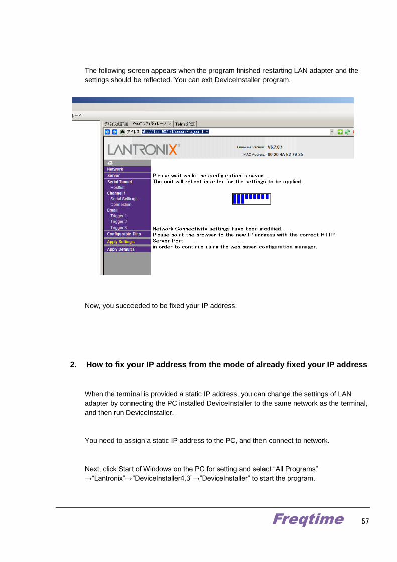
The following screen appears when the program finished restarting LAN adapter and the
settings should be reflected. You can exit DeviceInstaller program.
Now, you succeeded to be fixed your IP address.
2. How to fix your IP address from the mode of already fixed your IP address
When the terminal is provided a static IP address, you can change the settings of LAN
adapter by connecting the PC installed DeviceInstaller to the same network as the terminal,
and then run DeviceInstaller.
You need to assign a static IP address to the PC, and then connect to network.
Next, click Start of Windows on the PC for setting and select “All Programs”
→“Lantronix”→”DeviceInstaller4.3”→”DeviceInstaller” to start the program.

Freqtime 58
You can find the device named “Xport”. See previous section of “How to fix your IP address
from the mode of default settings or of automatically assigned IP address” and follow the steps
to change IP address.
Freqtime 59
Appendix
A-1 Introduction of CGGTTS Format
A-2 CGGTTS Header
A-3 CGGTTS Data part
A-4 Schedule of CGGTTS Format
A-5 Install Lantronix software “DeviceInstaller”
Freqtime 60
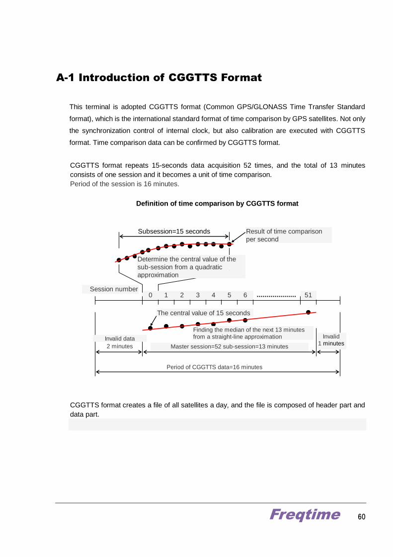
A-1 Introduction of CGGTTS Format
This terminal is adopted CGGTTS format (Common GPS/GLONASS Time Transfer Standard
format), which is the international standard format of time comparison by GPS satellites. Not only
the synchronization control of internal clock, but also calibration are executed with CGGTTS
format. Time comparison data can be confirmed by CGGTTS format.
CGGTTS format repeats 15-seconds data acquisition 52 times, and the total of 13 minutes
consists of one session and it becomes a unit of time comparison.
Period of the session is 16 minutes.
Definition of time comparison by CGGTTS format
Subsession=15 seconds
0 1 2 3 4 5 6 51 Session number
Determine the central value of the
sub-session from a quadratic
approximation
Master session=52 sub-session=13 minutes
Invalid 1 minutes
Finding the median of the next 13 minutes from a straight-line approximation
Result of time comparison
per second
Period of CGGTTS data=16 minutes
The central value of 15 seconds
Invalid data
2 minutes
CGGTTS format creates a file of all satellites a day, and the file is composed of header part and
data part.
Freqtime 61
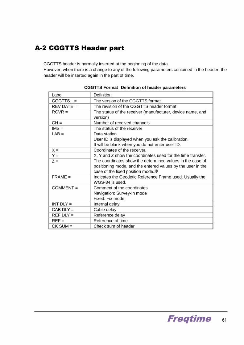
A-2 CGGTTS Header part
CGGTTS header is normally inserted at the beginning of the data.
However, when there is a change to any of the following parameters contained in the header, the
header will be inserted again in the part of time.
CGGTTS Format Definition of header parameters
Label Definition
CGGTTS…= The version of the CGGTTS format
REV DATE = The revision of the CGGTTS header format
RCVR = The status of the receiver (manufacturer, device name, and
version)
CH = Number of received channels
IMS = The status of the receiver
LAB = Data station
User ID is displayed when you ask the calibration.
It will be blank when you do not enter user ID.
X = Coordinates of the receiver.
X, Y and Z show the coordinates used for the time transfer.
The coordinates show the determined values in the case of
positioning mode, and the entered values by the user in the
case of the fixed position mode.測
Y =
Z =
FRAME = Indicates the Geodetic Reference Frame used. Usually the
WGS-84 is used.
COMMENT = Comment of the coordinates
Navigation: Survey-In mode
Fixed: Fix mode
INT DLY = Internal delay
CAB DLY = Cable delay
REF DLY = Reference delay
REF = Reference of time
CK SUM = Check sum of header
Freqtime 62
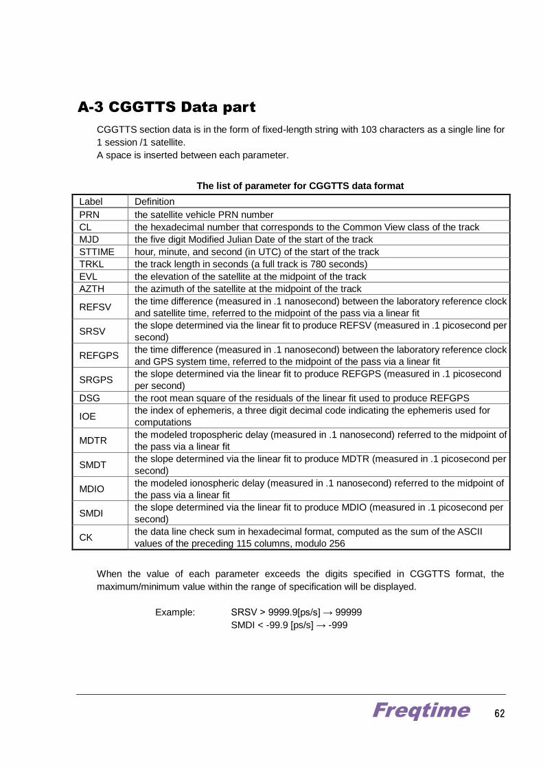
A-3 CGGTTS Data part
CGGTTS section data is in the form of fixed-length string with 103 characters as a single line for
1 session /1 satellite.
A space is inserted between each parameter.
The list of parameter for CGGTTS data format
Label Definition
PRN the satellite vehicle PRN number
CL the hexadecimal number that corresponds to the Common View class of the track
MJD the five digit Modified Julian Date of the start of the track
STTIME hour, minute, and second (in UTC) of the start of the track
TRKL the track length in seconds (a full track is 780 seconds)
EVL the elevation of the satellite at the midpoint of the track
AZTH the azimuth of the satellite at the midpoint of the track
REFSV the time difference (measured in .1 nanosecond) between the laboratory reference clock
and satellite time, referred to the midpoint of the pass via a linear fit
SRSV the slope determined via the linear fit to produce REFSV (measured in .1 picosecond per
second)
REFGPS the time difference (measured in .1 nanosecond) between the laboratory reference clock
and GPS system time, referred to the midpoint of the pass via a linear fit
SRGPS the slope determined via the linear fit to produce REFGPS (measured in .1 picosecond
per second)
DSG the root mean square of the residuals of the linear fit used to produce REFGPS
IOE the index of ephemeris, a three digit decimal code indicating the ephemeris used for
computations
MDTR the modeled tropospheric delay (measured in .1 nanosecond) referred to the midpoint of
the pass via a linear fit
SMDT the slope determined via the linear fit to produce MDTR (measured in .1 picosecond per
second)
MDIO the modeled ionospheric delay (measured in .1 nanosecond) referred to the midpoint of
the pass via a linear fit
SMDI the slope determined via the linear fit to produce MDIO (measured in .1 picosecond per
second)
CK the data line check sum in hexadecimal format, computed as the sum of the ASCII
values of the preceding 115 columns, modulo 256
When the value of each parameter exceeds the digits specified in CGGTTS format, the
maximum/minimum value within the range of specification will be displayed.
Example: SRSV > 9999.9[ps/s] → 99999
SMDI < -99.9 [ps/s] → -999
Freqtime 63
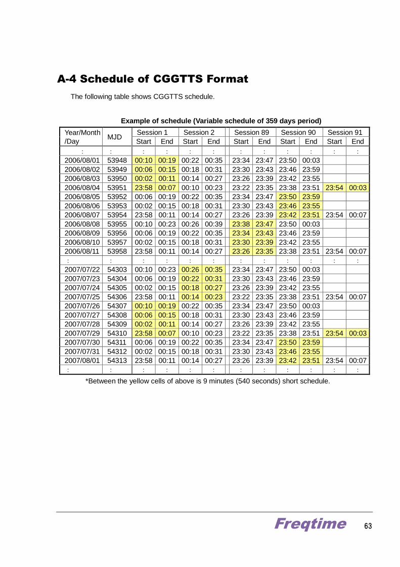
A-4 Schedule of CGGTTS Format
The following table shows CGGTTS schedule.
Example of schedule (Variable schedule of 359 days period)
Year/Month
/Day MJD
Session 1 Session 2 Session 89 Session 90 Session 91
Start End Start End Start End Start End Start End
: : : : : : : : : : : :
2006/08/01 53948 00:10 00:19 00:22 00:35 23:34 23:47 23:50 00:03
2006/08/02 53949 00:06 00:15 00:18 00:31 23:30 23:43 23:46 23:59
2006/08/03 53950 00:02 00:11 00:14 00:27 23:26 23:39 23:42 23:55
2006/08/04 53951 23:58 00:07 00:10 00:23 23:22 23:35 23:38 23:51 23:54 00:03
2006/08/05 53952 00:06 00:19 00:22 00:35 23:34 23:47 23:50 23:59
2006/08/06 53953 00:02 00:15 00:18 00:31 23:30 23:43 23:46 23:55
2006/08/07 53954 23:58 00:11 00:14 00:27 23:26 23:39 23:42 23:51 23:54 00:07
2006/08/08 53955 00:10 00:23 00:26 00:39 23:38 23:47 23:50 00:03
2006/08/09 53956 00:06 00:19 00:22 00:35 23:34 23:43 23:46 23:59
2006/08/10 53957 00:02 00:15 00:18 00:31 23:30 23:39 23:42 23:55
2006/08/11 53958 23:58 00:11 00:14 00:27 23:26 23:35 23:38 23:51 23:54 00:07
: : : : : : : : : : : :
2007/07/22 54303 00:10 00:23 00:26 00:35 23:34 23:47 23:50 00:03
2007/07/23 54304 00:06 00:19 00:22 00:31 23:30 23:43 23:46 23:59
2007/07/24 54305 00:02 00:15 00:18 00:27 23:26 23:39 23:42 23:55
2007/07/25 54306 23:58 00:11 00:14 00:23 23:22 23:35 23:38 23:51 23:54 00:07
2007/07/26 54307 00:10 00:19 00:22 00:35 23:34 23:47 23:50 00:03
2007/07/27 54308 00:06 00:15 00:18 00:31 23:30 23:43 23:46 23:59
2007/07/28 54309 00:02 00:11 00:14 00:27 23:26 23:39 23:42 23:55
2007/07/29 54310 23:58 00:07 00:10 00:23 23:22 23:35 23:38 23:51 23:54 00:03
2007/07/30 54311 00:06 00:19 00:22 00:35 23:34 23:47 23:50 23:59
2007/07/31 54312 00:02 00:15 00:18 00:31 23:30 23:43 23:46 23:55
2007/08/01 54313 23:58 00:11 00:14 00:27 23:26 23:39 23:42 23:51 23:54 00:07
: : : : : : : : : : : :
*Between the yellow cells of above is 9 minutes (540 seconds) short schedule.
Freqtime 64
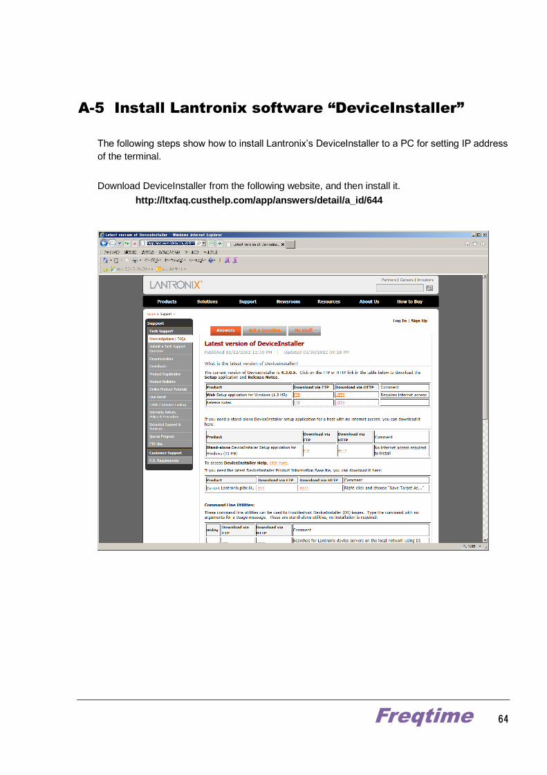
A-5 Install Lantronix software “DeviceInstaller”
The following steps show how to install Lantronix’s DeviceInstaller to a PC for setting IP address
of the terminal.
Download DeviceInstaller from the following website, and then install it.
http://ltxfaq.custhelp.com/app/answers/detail/a_id/644
Freqtime 65
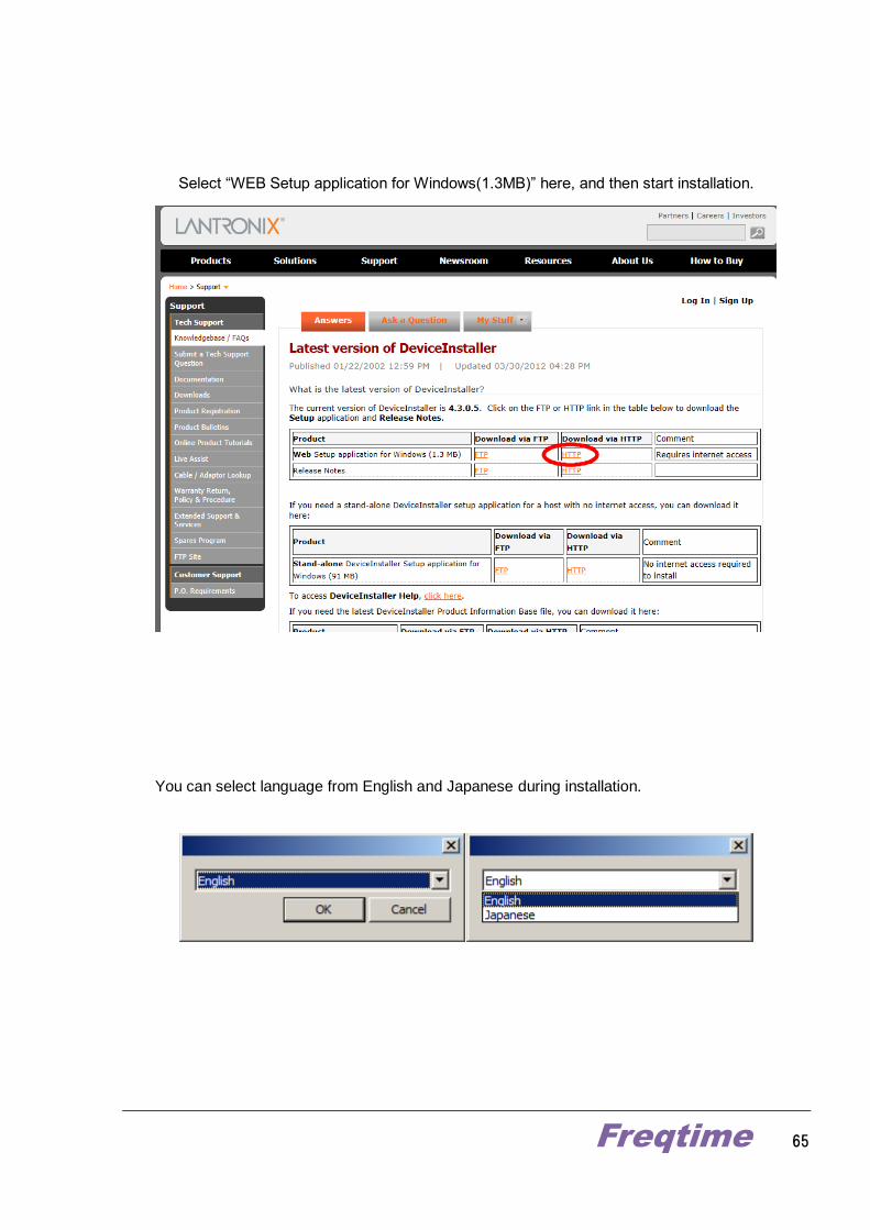
Select “WEB Setup application for Windows(1.3MB)” here, and then start installation.
You can select language from English and Japanese during installation.
Freqtime 66
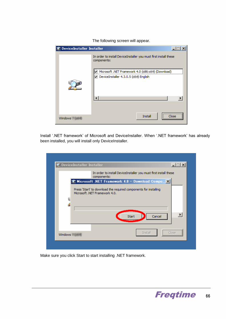
The following screen will appear.
Install ‘.NET framework’ of Microsoft and DeviceInstaller. When ‘.NET framework’ has already
been installed, you will install only DeviceInstaller.
Make sure you click Start to start installing .NET framework.
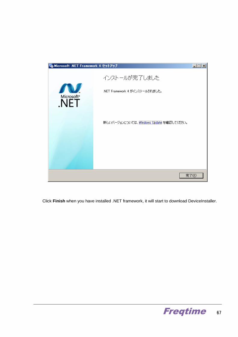
Freqtime 67
Click Finish when you have installed .NET framework, it will start to download DeviceInstaller.
Freqtime 68
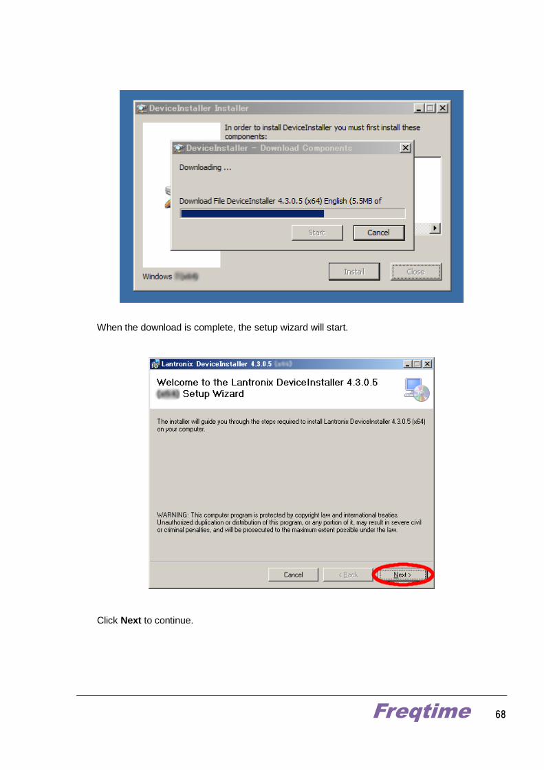
When the download is complete, the setup wizard will start.
Click Next to continue.
Freqtime 69
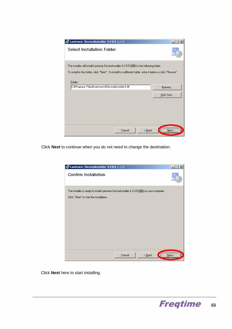
Click Next to continue when you do not need to change the destination.
Click Next here to start installing.
Freqtime 70
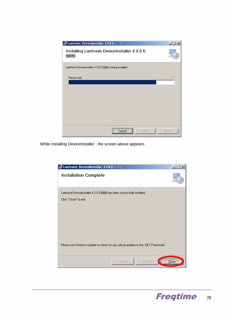
While Installing DeviceInstaller , the screen above appears.
Freqtime 71
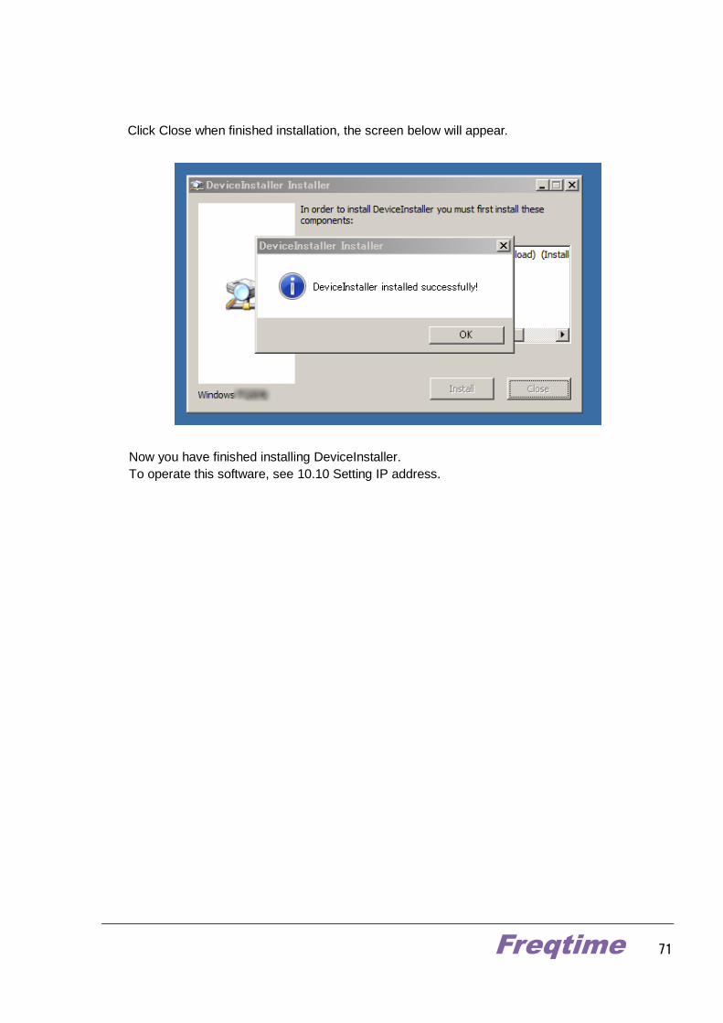
Click Close when finished installation, the screen below will appear.
Now you have finished installing DeviceInstaller.
To operate this software, see 10.10 Setting IP address.
Freqtime 72
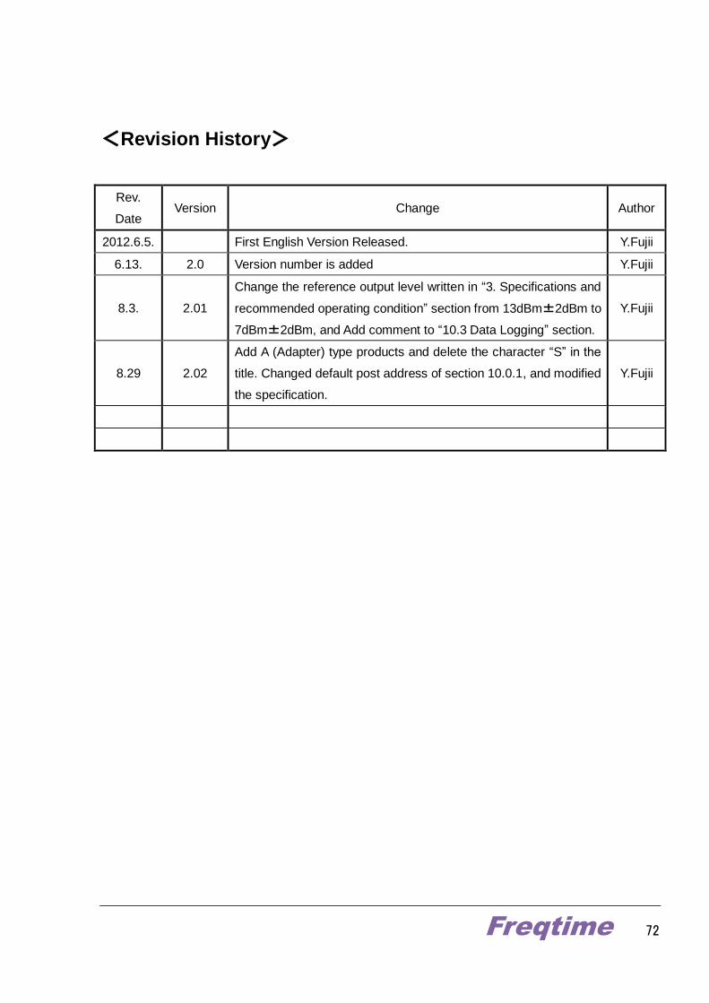
<Revision History>
Rev.
Date Version Change Author
2012.6.5. First English Version Released. Y.Fujii
6.13. 2.0 Version number is added Y.Fujii
8.3. 2.01
Change the reference output level written in “3. Specifications and
recommended operating condition” section from 13dBm±2dBm to
7dBm±2dBm, and Add comment to “10.3 Data Logging” section.
Y.Fujii
8.29 2.02
Add A (Adapter) type products and delete the character “S” in the
title. Changed default post address of section 10.0.1, and modified
the specification.
Y.Fujii