Embed Size (px)
Citation preview
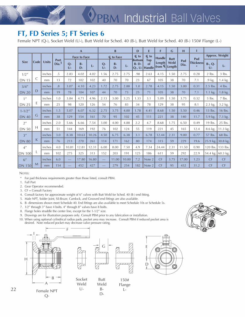
notes: * For pad thickness requirements greater than those listed, consult PBM. 1. Full Port 2. Gear Operator recommended. 3. CF = Consult Factory 4. Consult factory for approximate weight of 6” valves with Butt Weld for Sched. 40 (B-) end fitting. 5. Male NPT, Solder Joint, Sil-Braze, Camlock, and Grooved end fittings are also available. 6. B- dimensions shown meet Schedule 40. End fittings are also available to meet Schedule 10s or Schedule 5s. 7. 1/2” through 3” have 4 bolts. 4” through 8” valves have 8 bolts. 8. Flange holes straddle the center line, except for the 1-1/2” size. 9. Drawings are for illustration purposes only. Consult PBM prior to any fabrication or installation.10. When using optional cylindrical radius pads, pocket area may increase. Consult PBM if reduced pocket area is
desired. Note reduced pocket may decrease valve pressure rating.
FT, FD Series 5; FT Series 6
SK-A053
Female NPT (Q-), Socket Weld (U-), Butt Weld for Sched. 40 (B-), Butt Weld for Sched. 40 (B-) 150# Flange (L-)
A B D E F G H I
Size Code UnitsPortDia.1
Face to Face CL to Face CL toBottomB- D-Q-, U-
CL toTopof
Handle
HandleLengthfrom CL
Butt Weld
Length
Pad Dia.
PadThickness
*
Approx. Weight
Q-U-
B-D-
L-Q-U-
B-D-
L-B-, Q-
U-L-
1/2”
DN 15 Cinches .5 2.83 4.02 4.02 1.56 2.75 2.75 .98 2.63 4.15 1.50 2.75 0.28 2 lbs. 3 lbs.
mm 13 72 102 102 40 70 70 23 67 105 38 70 7.1 .9 kg. 1.4 kg.
3/4”
DN 20 Dinches .8 3.07 4.10 4.23 1.72 2.75 2.88 1.0 2.78 4.15 1.50 3.00 0.31 2.5 lbs. 4 lbs.
mm 19 78 104 107 44 70 73 25 71 105 38 70 7.1 1.1 kg. 1.8 kg.
1”
DN 25 Einches 1.0 3.84 4.71 4.96 2.13 3.00 3.25 1.33 3.1 5.09 1.50 3.75 0.32 5 lbs. 7 lbs.
mm 25 98 120 126 54 76 83 34 78 129 38 95 8.1 2.3 kg. 3.2 kg.
1-1/2”
DN 40 Ginches 1.5 5.07 6.07 6.32 2.75 3.75 4.00 1.78 4.41 8.68 1.50 5.50 0.46 13 lbs. 16 lbs.
mm 38 129 154 161 70 95 102 45 111 221 38 140 11.7 5.9 kg. 7.3 kg.
2”
DN 50 Hinches 2.0 5.66 6.66 7.54 3.00 4.00 4.88 2.2 4.7 8.68 1.75 6.50 0.49 19 lbs. 25 lbs.
mm 51 144 169 192 76 102 124 55 119 221 45 165 12.4 8.6 kg. 11.3 kg.
3”
DN 80 Kinches 3.0 8.38 10.63 10.26 4.50 6.75 6.38 3.1 6.78 12.44 2.31 9.00 0.77 57 lbs. 68 lbs.
mm 76 213 270 261 114 171 162 80 174 315 59 229 19.6 25.9 kg. 30.8 kg.
4”
DN 100 Linches 4.0 10.81 12.81 12.31 6.00 8.00 7.50 4.9 7.34 24.44 2.31 11.50 0.90 120 lbs. 133 lbs.
mm 102 275 325 313 152 203 191 125 186 611 59 292 22.9 54.4 kg. 60.3 kg.
6”
DN 150 Minches 6.0 — 17.80 16.80 — 11.00 10.00 7.2 Note 2 CF 3.75 17.00 1.23 CF CF
mm 154 — 452 427 — 279 254 182 Note 2 CF 95 432 31.2 CF CF
A B
G
F
E
D
I
H
Female NPT Q-
150# Flange
L-
Butt Weld
B-D-
SocketWeld
U-22
TFMTM OR VTFE SEAT MATERIAL
Size Actuator Type Air Supply A B C D E F
psig barg inches mm inches mm inches mm inches mm NPT inches mm
1/2”DN 15
Double Acting 60, 80 4.1/5.5 5.55 141 2.80 71 5.84 148 1.61 41 1/8 0.09 2
Spring Return 80 5.5 5.55 141 2.80 71 5.84 148 1.61 41 1/8 0.09 2
Spring Return 60 4.1 6.46 164 3.17 81 6.29 160 1.77 45 1/8 -0.13 -3
3/4”DN 20
Double Acting 60, 80 4.1/5.5 5.55 141 2.80 71 5.99 152 1.61 41 1/8 0.17 4
Spring Return 60, 80 4.1/5.5 6.46 164 3.17 81 6.44 164 1.77 46 1/8 -0.05 -1
1”DN 25
Double Acting 60, 80 4.1/5.5 5.55 141 2.80 71 6.64 169 1.61 41 1/8 0.53 13
Spring Return 60, 80 4.1/5.5 8.27 210 3.72 94 7.8 198 2.07 53 1/8 0.06 2
1-1/2”DN 40
Double Acting 80 5.5 6.46 164 3.17 81 8.39 213 1.77 45 1/8 0.92 23
Double Acting 60 4.1 8.27 210 3.72 94 9.1 231 2.07 53 1/8 0.67 17
Spring Return 60, 80 4.1/5.5 10.83 275 4.84 123 10.15 258 2.68 68 1/4 0.15 4
2”DN 50
Double Acting 60, 80 4.1/5.5 8.27 210 3.72 94 9.41 239 2.07 53 1/8 1.01 26
Spring Return 80 5.5 10.83 275 4.84 123 10.46 266 2.68 68 1/4 0.49 12
Spring Return 60 4.1 13.11 333 5.39 137 11.82 300 2.87 73 1/4 0.14 4
3”DN 80
Double Acting 60, 80 4.1/5.5 13.11 333 5.39 137 13.81 351 2.87 73 1/4 1.36 35
Spring Return 80 5.5 14.65 372 5.83 148 14.29 363 3.15 80 1/4 1.20 30
Spring Return 60 4.1 17.15 436 6.46 164 15.18 386 3.44 87 1/4 0.85 22
4”DN 100
Double Acting 60, 80 4.1/5.5 17.15 436 6.46 164 17.34 440 3.44 87 1/4 1.78 45
Spring Return 60, 80 4.1/5.5 19.69 500 7.36 187 18.28 464 3.94 100 1/4 1.38 35
6”DN 150
Double Acting 60, 80 4.1/5.5 22.78 579 8.58 218 24.13 613 4.29 109 1/4 2.51 64
Spring Return 80 5.5 22.78 579 8.58 218 24.13 613 4.29 109 1/4 2.51 64
Spring Return 60 4.1 26.46 672 11.42 290 28.89 734 5.71 145 1/4 1.09 28
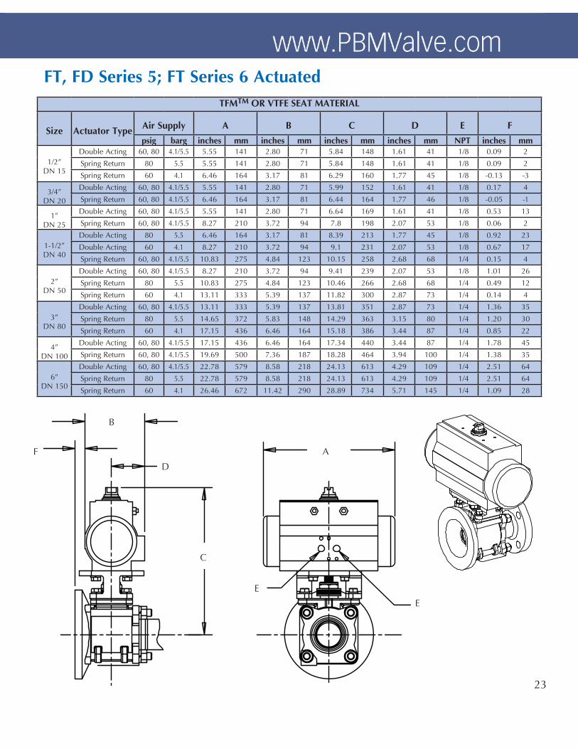
FT, FD Series 5; FT Series 6 Actuated
A
B
E
F
E
C
23
D

B C D H I J
Size Units PortFace-to-Face CL to End
Pad Diameter
PadThickness
HandleLengthQ-, B-, U- L- Q-, B-, U- L-
1”DN 25
inches 1.00 3.58 4.14 1.94 2.50 3.70 0.53 6.09
mm 25 91 105 49 64 94 13 155
1-1/2”DN 40
inches 1.50 4.97 5.53 2.69 3.25 5.50 0.62 8.07
mm 38 126 140 68 83 140 16 205
2”DN 50
inches 2.00 5.53 6.17 2.86 3.50 7.00 0.68 8.07
mm 51 140 157 73 89 178 17 205
3”DN 80
inches 2.75 8.38 9.19 4.31 5.12 10.00 0.79 12.06
mm 70 213 233 109 130 254 20 306
4”DN 100
inches 3.50 9.52 10.48 5.24 6.20 11.50 0.91 12.06
mm 89 242 266 133 157 292 23 306
6”DN 150
inches 5.25 12.12 15.61 6.56 10.05 15.00 1.04 15.06
mm 133 308 396 167 255 381 26 383
AF Series 1 & 3
A_14A_15
1”, 1-1/2”, & 8” = 10º2”, 3”, 4”, & 6” = 15º
Q- = Female NPT OutletU- = Socket Weld OutletL- = 150# ANSI Flange Outlet
H
C
< degrees
I D
*Buttweld end; Q and U not available in 6” size.
J
24
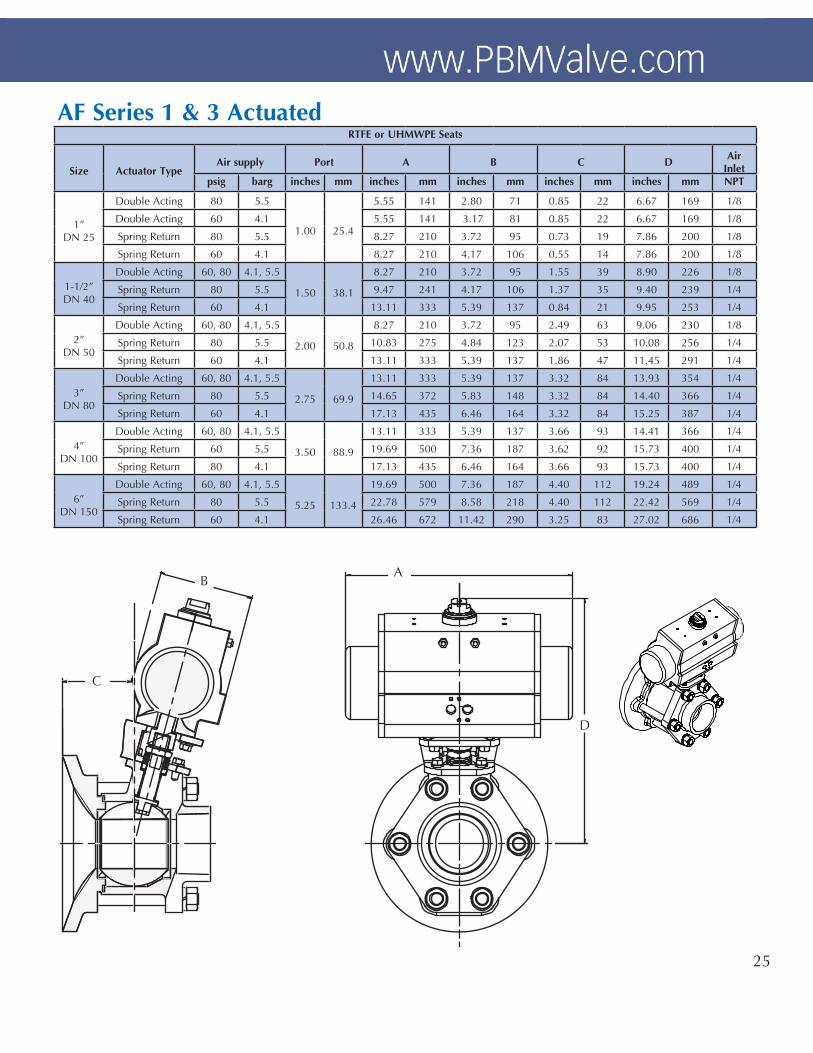
AF Series 1 & 3 ActuatedRTFE or UHMWPE Seats
Size Actuator TypeAir supply Port A B C D
AirInlet
psig barg inches mm inches mm inches mm inches mm inches mm NPT
1”DN 25
Double Acting 80 5.5
1.00 25.4
5.55 141 2.80 71 0.85 22 6.67 169 1/8
Double Acting 60 4.1 5.55 141 3.17 81 0.85 22 6.67 169 1/8
Spring Return 80 5.5 8.27 210 3.72 95 0.73 19 7.86 200 1/8
Spring Return 60 4.1 8.27 210 4.17 106 0.55 14 7.86 200 1/8
1-1/2”DN 40
Double Acting 60, 80 4.1, 5.5
1.50 38.1
8.27 210 3.72 95 1.55 39 8.90 226 1/8
Spring Return 80 5.5 9.47 241 4.17 106 1.37 35 9.40 239 1/4
Spring Return 60 4.1 13.11 333 5.39 137 0.84 21 9.95 253 1/4
2”DN 50
Double Acting 60, 80 4.1, 5.5
2.00 50.8
8.27 210 3.72 95 2.49 63 9.06 230 1/8
Spring Return 80 5.5 10.83 275 4.84 123 2.07 53 10.08 256 1/4
Spring Return 60 4.1 13.11 333 5.39 137 1.86 47 11.45 291 1/4
3”DN 80
Double Acting 60, 80 4.1, 5.5
2.75 69.9
13.11 333 5.39 137 3.32 84 13.93 354 1/4
Spring Return 80 5.5 14.65 372 5.83 148 3.32 84 14.40 366 1/4
Spring Return 60 4.1 17.13 435 6.46 164 3.32 84 15.25 387 1/4
4”DN 100
Double Acting 60, 80 4.1, 5.5
3.50 88.9
13.11 333 5.39 137 3.66 93 14.41 366 1/4
Spring Return 60 5.5 19.69 500 7.36 187 3.62 92 15.73 400 1/4
Spring Return 80 4.1 17.13 435 6.46 164 3.66 93 15.73 400 1/4
6”DN 150
Double Acting 60, 80 4.1, 5.5
5.25 133.4
19.69 500 7.36 187 4.40 112 19.24 489 1/4
Spring Return 80 5.5 22.78 579 8.58 218 4.40 112 22.42 569 1/4
Spring Return 60 4.1 26.46 672 11.42 290 3.25 83 27.02 686 1/4
A B
C
D
25

Designation Description Color Purpose
TFMTM
Chemically Modified PTFE
PBM Standard for Series 4, 5 6, & 7
White
Suitable for applications under 400˚F. This chemically modified PTFE material is PBM’s standard seat and seal material. It combines the ruggedness of a filled PTFE with the low coefficient of friction of virgin PTFE. TFMTM also has much improved porosity control and deformation under load when compared to PTFE grades. FDA and USP Class VI compliant. Meets bubbletight seat leakage.
RTFE Glass Reinforced PTFE Slightly Off White
Suitable for applications under 400˚F. Used in a variety of applications. Bubbletight leakage.
VTFE Virgin PTFE White Suitable for applications under 350˚F. A low stem torque material ideal for sanitary use. FDA and USP Class VI compliant. Meets bubbletight seat leakage.
S-TEF® Stainless Steel Reinforced PTFE
Charcoal Gray
Suitable for applications under 450˚F. A suitable material for higher pressure/temperature applications. Higher stem torque than virgin grades and TFMTM. USP Class VI compliant. Meets bubbletight seat leakage.
CARBON Carbon/Graphite BlackSuitable for applications under 750˚F (400˚C). A hard material impervious to high temperatures. It is used for heat transfer fluid applications and other high temperature applications. Meets Class V seat leakage.
UHMWPEUltra High Molecular Weight Polyethylene Off White
Suitable for applications under 200˚F. An extremely wear resistant material having a wear rate about 1/10th that of PTFE. FDA compliant and is used in high cycle applications where possible. Meets bubbletight seat leakage.
PEEK® Poly ether ether ketone PuttySuitable for applications under 500˚F. PEEK® is a rugged, high strength material having fairly high stem torque. PBM’s PEEK® is 10 weight percent PTFE to reduce the hardness of virgin PEEK®. FDA compliant and meets Class V seat leakage.
KYNAR® Polyvinylidene FluorideSlightly
Transparent White
Suitable for applications under 250˚F. Kynar® has been used successfully in abrasive service and is suitable for radiation environments where gamma levels accumulate to 1,000 megarads. FDA and USP Class VI compliant. Meets bubbletight seat leakage.
NOTES:1. PTFE is Polytetrafluorethylene.2. Seat and seal materials may be mixed in a valve in order to provide media-compatibility and the appropriate torque, temperature and pressure ratings.3. Temperature ratings above based on 0 psi. See Pressure & Temperature charts on page 8.
Stainless Steel316 S/S complies with ASTM A 351-CF8M or A479, S31600316L S/S complies with ASTM A 351-CF3M or A479, S31603• Is exceptionally corrosion-resistant to acidic and basic environments and does not pit easily.• Can be polished to a near-mirror finish for easy cleanability.• Weld fittings have a carbon content of <.03% to facilitate welding.
Carbon Steel, A216-WCB• This versatile material handles mildly corrosive media.
Bronze, Alloy 922• Excellent resistance to sea water environments and good steam resistance. Also, suitable for sub-zero temperature applications.
Hastelloy® C-276• Very good corrosion in reducing and mildly oxidizing environments. Very good resistance to localized attack and very
good resistance to stress corrosion cracking. Alloy CW-12MW in cast form. Others • Additional materials are available, including Alloy 20, Bronze, Duplex Stainless Steels, Hastelloys, Titanium, and
Inconel®.
Materials
Seat and Seal Materials
6
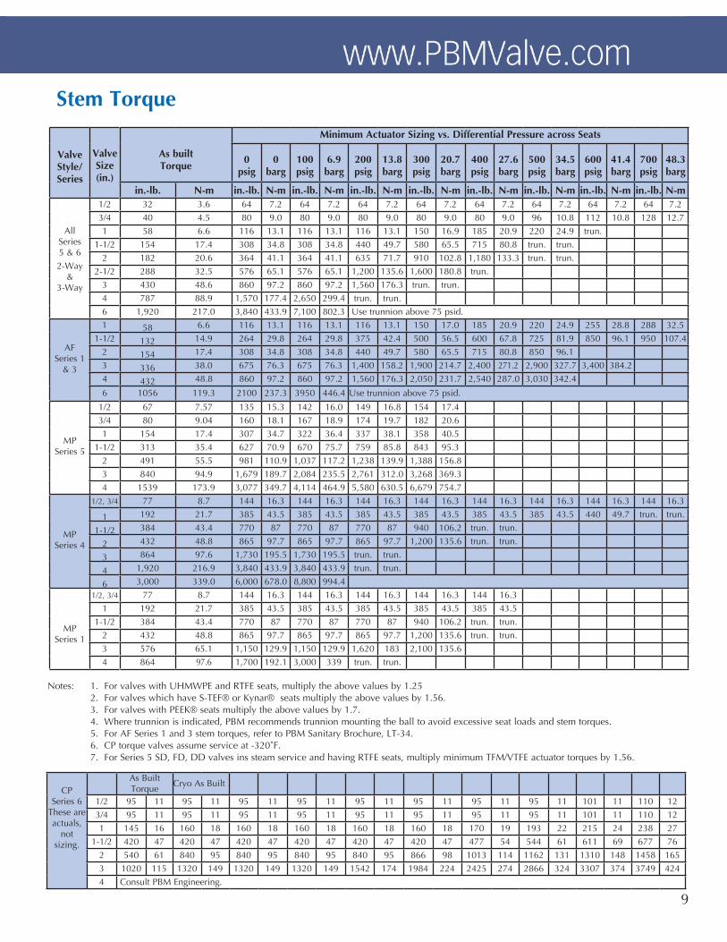
ValveStyle/Series
Valve Size(in.)
As builtTorque
Minimum Actuator Sizing vs. Differential Pressure across Seats
0psig
0barg
100psig
6.9barg
200psig
13.8barg
300psig
20.7barg
400psig
27.6barg
500psig
34.5barg
600psig
41.4barg
700psig
48.3barg
in.-lb. N-m in.-lb. N-m in.-lb. N-m in.-lb. N-m in.-lb. N-m in.-lb. N-m in.-lb. N-m in.-lb. N-m in.-lb. N-m
AllSeries 5 & 62-Way
&3-Way
1/2 32 3.6 64 7.2 64 7.2 64 7.2 64 7.2 64 7.2 64 7.2 64 7.2 64 7.2
3/4 40 4.5 80 9.0 80 9.0 80 9.0 80 9.0 80 9.0 96 10.8 112 10.8 128 12.7
1 58 6.6 116 13.1 116 13.1 116 13.1 150 16.9 185 20.9 220 24.9 trun.
1-1/2 154 17.4 308 34.8 308 34.8 440 49.7 580 65.5 715 80.8 trun. trun.
2 182 20.6 364 41.1 364 41.1 635 71.7 910 102.8 1,180 133.3 trun. trun.
2-1/2 288 32.5 576 65.1 576 65.1 1,200 135.6 1,600 180.8 trun.
3 430 48.6 860 97.2 860 97.2 1,560 176.3 trun. trun.
4 787 88.9 1,570 177.4 2,650 299.4 trun. trun.
6 1,920 217.0 3,840 433.9 7,100 802.3 Use trunnion above 75 psid.
AFSeries 1
& 3
1 58 6.6 116 13.1 116 13.1 116 13.1 150 17.0 185 20.9 220 24.9 255 28.8 288 32.5
1-1/2 132 14.9 264 29.8 264 29.8 375 42.4 500 56.5 600 67.8 725 81.9 850 96.1 950 107.4
2 154 17.4 308 34.8 308 34.8 440 49.7 580 65.5 715 80.8 850 96.1
3 336 38.0 675 76.3 675 76.3 1,400 158.2 1,900 214.7 2,400 271.2 2,900 327.7 3,400 384.2
4 432 48.8 860 97.2 860 97.2 1,560 176.3 2,050 231.7 2,540 287.0 3,030 342.4
6 1056 119.3 2100 237.3 3950 446.4 Use trunnion above 75 psid.
MPSeries 5
1/2 67 7.57 135 15.3 142 16.0 149 16.8 154 17.43/4 80 9.04 160 18.1 167 18.9 174 19.7 182 20.6
1 154 17.4 307 34.7 322 36.4 337 38.1 358 40.5
1-1/2 313 35.4 627 70.9 670 75.7 759 85.8 843 95.3
2 491 55.5 981 110.9 1,037 117.2 1,238 139.9 1,388 156.8
3 840 94.9 1,679 189.7 2,084 235.5 2,761 312.0 3,268 369.3
4 1539 173.9 3,077 349.7 4,114 464.9 5,580 630.5 6,679 754.7
MP Series 4
1/2, 3/4 77 8.7 144 16.3 144 16.3 144 16.3 144 16.3 144 16.3 144 16.3 144 16.3 144 16.3
1 192 21.7 385 43.5 385 43.5 385 43.5 385 43.5 385 43.5 385 43.5 440 49.7 trun. trun.
1-1/2 384 43.4 770 87 770 87 770 87 940 106.2 trun. trun.
2 432 48.8 865 97.7 865 97.7 865 97.7 1,200 135.6 trun. trun.
3 864 97.6 1,730 195.5 1,730 195.5 trun. trun.
4 1,920 216.9 3,840 433.9 3,840 433.9 trun. trun.
6 3,000 339.0 6,000 678.0 8,800 994.4
MP Series 1
1/2, 3/4 77 8.7 144 16.3 144 16.3 144 16.3 144 16.3 144 16.3
1 192 21.7 385 43.5 385 43.5 385 43.5 385 43.5 385 43.5
1-1/2 384 43.4 770 87 770 87 770 87 940 106.2 trun. trun.
2 432 48.8 865 97.7 865 97.7 865 97.7 1,200 135.6 trun. trun.
3 576 65.1 1,150 129.9 1,150 129.9 1,620 183 2,100 135.6
4 864 97.6 1,700 192.1 3,000 339 trun. trun.
Notes: 1. For valves with UHMWPE and RTFE seats, multiply the above values by 1.25 2. For valves which have S-TEF® or Kynar® seats multiply the above values by 1.56. 3. For valves with PEEK® seats multiply the above values by 1.7. 4. Where trunnion is indicated, PBM recommends trunnion mounting the ball to avoid excessive seat loads and stem torques. 5. For AF Series 1 and 3 stem torques, refer to PBM Sanitary Brochure, LT-34. 6. CP torque valves assume service at -320˚F. 7. For Series 5 SD, FD, DD valves ins steam service and having RTFE seats, multiply minimum TFM/VTFE actuator torques by 1.56.
Stem Torque
9
CPSeries 6
These are actuals,
not sizing.
As Built Torque
Cryo As Built
1/2 95 11 95 11 95 11 95 11 95 11 95 11 95 11 95 11 101 11 110 12
3/4 95 11 95 11 95 11 95 11 95 11 95 11 95 11 95 11 101 11 110 12
1 145 16 160 18 160 18 160 18 160 18 160 18 170 19 193 22 215 24 238 27
1-1/2 420 47 420 47 420 47 420 47 420 47 420 47 477 54 544 61 611 69 677 76
2 540 61 840 95 840 95 840 95 840 95 866 98 1013 114 1162 131 1310 148 1458 165
3 1020 115 1320 149 1320 149 1320 149 1542 174 1984 224 2425 274 2866 324 3307 374 3749 424
4 Consult PBM Engineering.
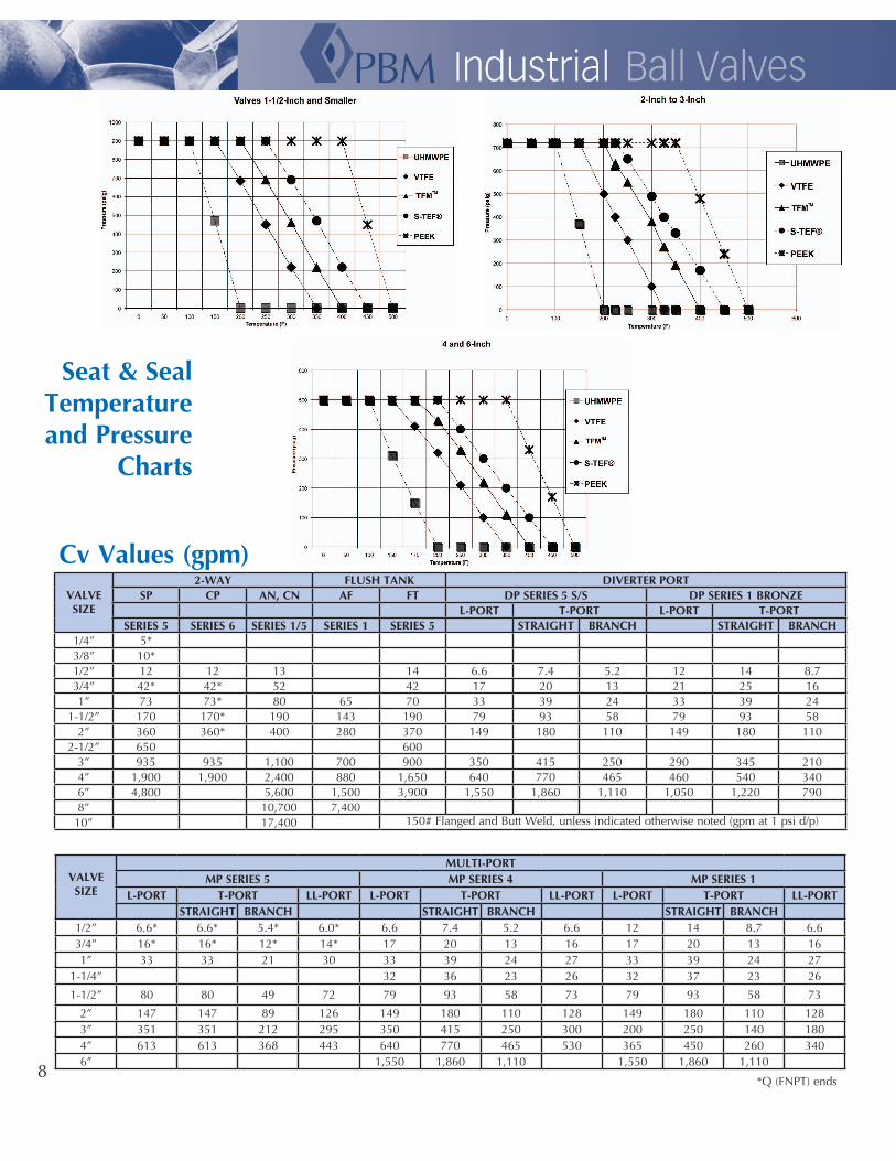
VALVE SIZE
2-WAY FLUSH TANK DIVERTER PORTSP CP AN, CN AF FT DP SERIES 5 S/S DP SERIES 1 BRONZE
L-PORT T-PORT L-PORT T-PORTSERIES 5 SERIES 6 SERIES 1/5 SERIES 1 SERIES 5 STRAIGHT BRANCH STRAIGHT BRANCH
1/4” 5*3/8” 10*1/2” 12 12 13 14 6.6 7.4 5.2 12 14 8.73/4” 42* 42* 52 42 17 20 13 21 25 161” 73 73* 80 65 70 33 39 24 33 39 24
1-1/2” 170 170* 190 143 190 79 93 58 79 93 582” 360 360* 400 280 370 149 180 110 149 180 110
2-1/2” 650 6003” 935 935 1,100 700 900 350 415 250 290 345 2104” 1,900 1,900 2,400 880 1,650 640 770 465 460 540 3406” 4,800 5,600 1,500 3,900 1,550 1,860 1,110 1,050 1,220 7908” 10,700 7,40010” 17,400 150# Flanged and Butt Weld, unless indicated otherwise noted (gpm at 1 psi d/p)
VALVE SIZE
MULTI-PORTMP SERIES 5 MP SERIES 4 MP SERIES 1
L-PORT T-PORT LL-PORT L-PORT T-PORT LL-PORT L-PORT T-PORT LL-PORTSTRAIGHT BRANCH STRAIGHT BRANCH STRAIGHT BRANCH
1/2” 6.6* 6.6* 5.4* 6.0* 6.6 7.4 5.2 6.6 12 14 8.7 6.63/4” 16* 16* 12* 14* 17 20 13 16 17 20 13 161” 33 33 21 30 33 39 24 27 33 39 24 27
1-1/4” 32 36 23 26 32 37 23 26
1-1/2” 80 80 49 72 79 93 58 73 79 93 58 73
2” 147 147 89 126 149 180 110 128 149 180 110 1283” 351 351 212 295 350 415 250 300 200 250 140 1804” 613 613 368 443 640 770 465 530 365 450 260 3406” 1,550 1,860 1,110 1,550 1,860 1,110
Cv Values (gpm)
*Q (FNPT) ends
Seat & Seal Temperature and Pressure
Charts
8
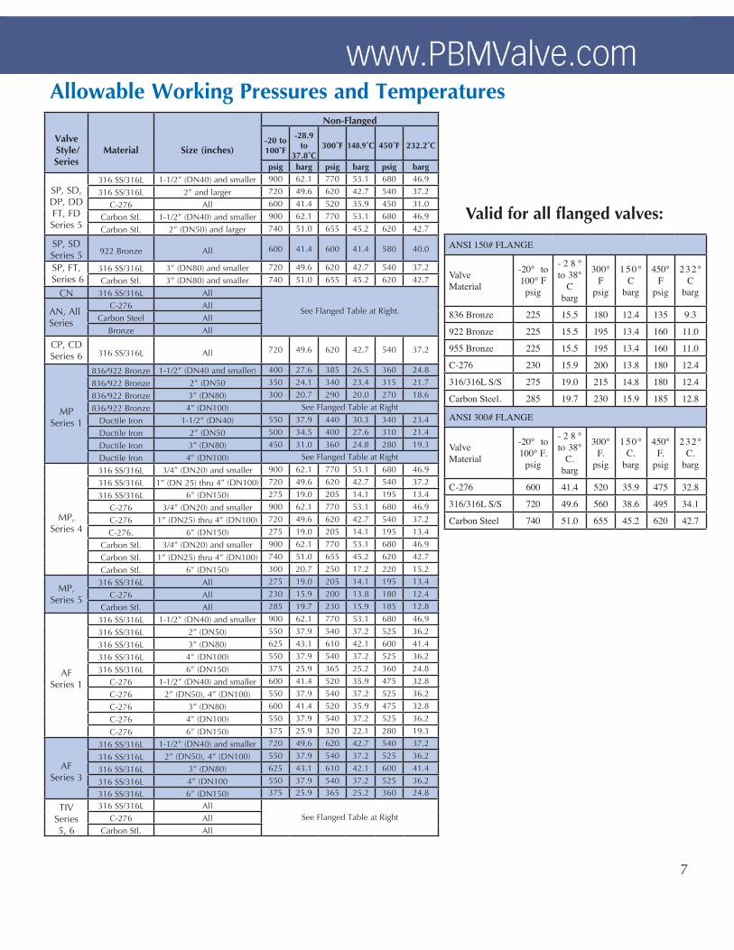
Allowable Working Pressures and Temperatures
7
Valve Style/Series
Material Size (inches)
Non-Flanged
-20 to 100˚F
-28.9 to
37.8˚C300˚F 148.9˚C 450˚F 232.2˚C
psig barg psig barg psig barg
SP, SD,DP, DDFT, FDSeries 5
316 SS/316L 1-1/2” (DN40) and smaller 900 62.1 770 53.1 680 46.9
316 SS/316L 2” and larger 720 49.6 620 42.7 540 37.2
C-276 All 600 41.4 520 35.9 450 31.0
Carbon Stl. 1-1/2” (DN40) and smaller 900 62.1 770 53.1 680 46.9
Carbon Stl. 2” (DN50) and larger 740 51.0 655 45.2 620 42.7
SP, SDSeries 5 922 Bronze All 600 41.4 600 41.4 580 40.0
SP, FT, Series 6
316 SS/316L 3” (DN80) and smaller 720 49.6 620 42.7 540 37.2
Carbon Stl. 3” (DN80) and smaller 740 51.0 655 45.2 620 42.7
CN 316 SS/316L All
See Flanged Table at Right.AN, AllSeries
C-276 AllCarbon Steel All
Bronze All
CP, CD Series 6 316 SS/316L All 720 49.6 620 42.7 540 37.2
MPSeries 1
836/922 Bronze 1-1/2” (DN40 and smaller) 400 27.6 385 26.5 360 24.8
836/922 Bronze 2” (DN50 350 24.1 340 23.4 315 21.7
836/922 Bronze 3” (DN80) 300 20.7 290 20.0 270 18.6
836/922 Bronze 4” (DN100) See Flanged Table at Right
Ductile Iron 1-1/2” (DN40) 550 37.9 440 30.3 340 23.4
Ductile Iron 2” (DN50 500 34.5 400 27.6 310 21.4
Ductile Iron 3” (DN80) 450 31.0 360 24.8 280 19.3
Ductile Iron 4” (DN100) See Flanged Table at Right
MP, Series 4
316 SS/316L 3/4” (DN20) and smaller 900 62.1 770 53.1 680 46.9
316 SS/316L 1” (DN 25) thru 4” (DN100) 720 49.6 620 42.7 540 37.2
316 SS/316L 6” (DN150) 275 19.0 205 14.1 195 13.4
C-276 3/4” (DN20) and smaller 900 62.1 770 53.1 680 46.9
C-276 1” (DN25) thru 4” (DN100) 720 49.6 620 42.7 540 37.2
C-276. 6” (DN150) 275 19.0 205 14.1 195 13.4
Carbon Stl. 3/4” (DN20) and smaller 900 62.1 770 53.1 680 46.9
Carbon Stl. 1” (DN25) thru 4” (DN100) 740 51.0 655 45.2 620 42.7
Carbon Stl. 6” (DN150) 300 20.7 250 17.2 220 15.2
MP, Series 5
316 SS/316L All 275 19.0 205 14.1 195 13.4
C-276 All 230 15.9 200 13.8 180 12.4
Carbon Stl. All 285 19.7 230 15.9 185 12.8
AF Series 1
316 SS/316L 1-1/2” (DN40) and smaller 900 62.1 770 53.1 680 46.9
316 SS/316L 2” (DN50) 550 37.9 540 37.2 525 36.2
316 SS/316L 3” (DN80) 625 43.1 610 42.1 600 41.4
316 SS/316L 4” (DN100) 550 37.9 540 37.2 525 36.2
316 SS/316L 6” (DN150) 375 25.9 365 25.2 360 24.8
C-276 1-1/2” (DN40) and smaller 600 41.4 520 35.9 475 32.8
C-276 2” (DN50), 4” (DN100) 550 37.9 540 37.2 525 36.2
C-276 3” (DN80) 600 41.4 520 35.9 475 32.8
C-276 4” (DN100) 550 37.9 540 37.2 525 36.2
C-276 6” (DN150) 375 25.9 320 22.1 280 19.3
AF Series 3
316 SS/316L 1-1/2” (DN40) and smaller 720 49.6 620 42.7 540 37.2
316 SS/316L 2” (DN50), 4” (DN100) 550 37.9 540 37.2 525 36.2
316 SS/316L 3” (DN80) 625 43.1 610 42.1 600 41.4
316 SS/316L 4” (DN100 550 37.9 540 37.2 525 36.2
316 SS/316L 6” (DN150) 375 25.9 365 25.2 360 24.8
TIVSeries 5, 6
316 SS/316L AllSee Flanged Table at RightC-276 All
Carbon Stl. All
ANSI 150# FLANGE
ValveMaterial
-20° to 100° F
psig
- 2 8 ° to 38°
Cbarg
300° F
psig
1 5 0 ° C
barg
450° F
psig
2 3 2 ° C
barg
836 Bronze 225 15.5 180 12.4 135 9.3
922 Bronze 225 15.5 195 13.4 160 11.0
955 Bronze 225 15.5 195 13.4 160 11.0
C-276 230 15.9 200 13.8 180 12.4
316/316L S/S 275 19.0 215 14.8 180 12.4
Carbon Steel. 285 19.7 230 15.9 185 12.8
ANSI 300# FLANGE
Valve Material
-20° to 100° F.
psig
- 2 8 ° to 38°
C.barg
300° F.
psig
1 5 0 ° C.
barg
450° F.
psig
2 3 2 ° C.
barg
C-276 600 41.4 520 35.9 475 32.8
316/316L S/S 720 49.6 560 38.6 495 34.1
Carbon Steel 740 51.0 655 45.2 620 42.7
Valid for all flanged valves:
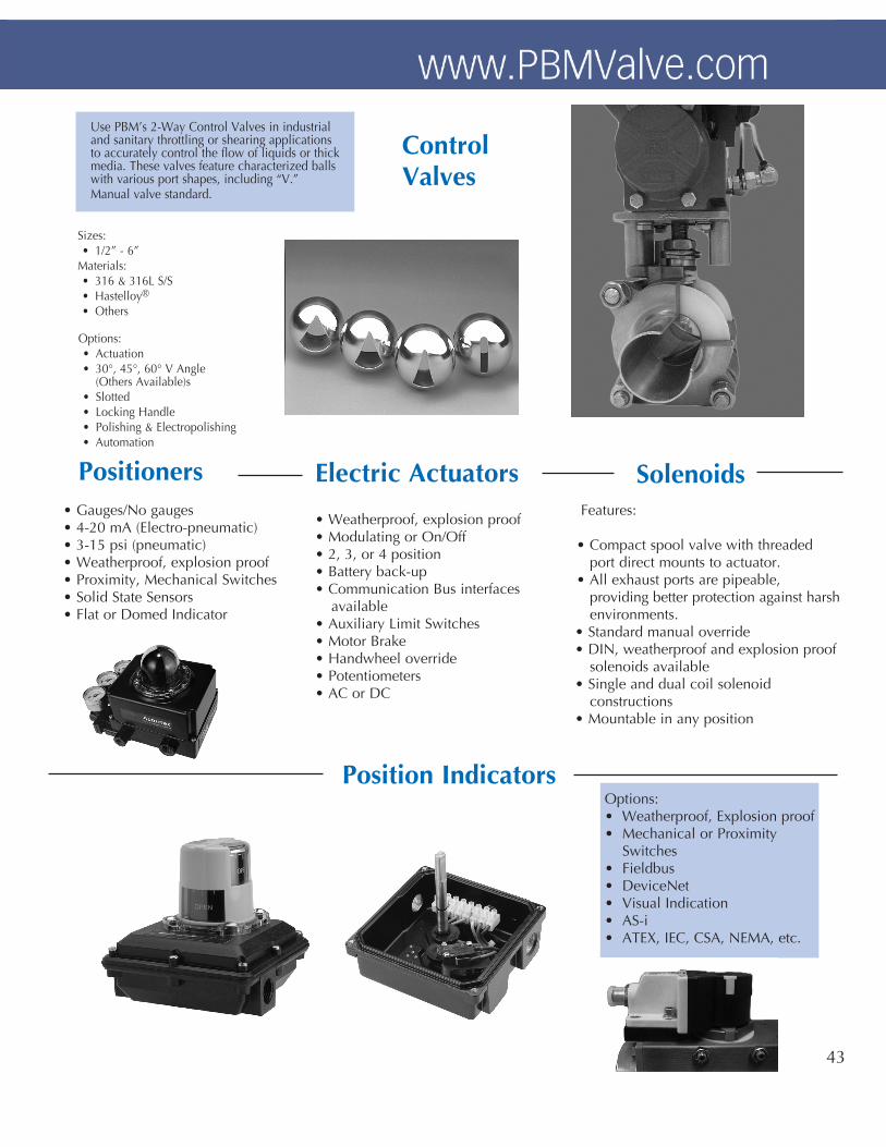
Features:
• Compact spool valve with threaded port direct mounts to actuator.• All exhaust ports are pipeable, providing better protection against harsh environments.• Standard manual override• DIN, weatherproof and explosion proof solenoids available• Single and dual coil solenoid constructions• Mountable in any position
Positioners Electric Actuators
Position Indicators
Solenoids
Options:• Weatherproof, Explosion proof• Mechanical or Proximity Switches• Fieldbus• DeviceNet• Visual Indication• AS-i• ATEX, IEC, CSA, NEMA, etc.
Use PBM’s 2-Way Control Valves in industrial and sanitary throttling or shearing applications to accurately control the flow of liquids or thick media. These valves feature characterized balls with various port shapes, including “V.” Manual valve standard.
Sizes: • 1/2” - 6”Materials: • 316 & 316L S/S • Hastelloy®
• Others
Options: • Actuation • 30°, 45°, 60° V Angle (Others Available)s • Slotted • Locking Handle • Polishing & Electropolishing • Automation
Control Valves
• Weatherproof, explosion proof• Modulating or On/Off• 2, 3, or 4 position• Battery back-up• Communication Bus interfaces available• Auxiliary Limit Switches• Motor Brake• Handwheel override• Potentiometers• AC or DC
• Gauges/No gauges• 4-20 mA (Electro-pneumatic)• 3-15 psi (pneumatic)• Weatherproof, explosion proof• Proximity, Mechanical Switches• Solid State Sensors• Flat or Domed Indicator
43

Actuator Model
Air pressure at actuator (psig)
60 psig 80 psig
Constant Torque Output (in-lbs)
PAVCL453D - - 0052 133 179
PAVCL453D - - 0063 238 321
PAVCL453D - - 0075 435 586
PAVCL453D - - 0085 629 851
PAVCL453D - - 0100 991 1,336
PAVCL453D - - 0115 1,640 2,210
PAVCL453D - - 0125 2,157 2,906
PAVCL453D - - 0140 3,013 4,018
PAVCL453D - - 0160 4,394 5,859
PAVCL453D - - 0200 8,239 10,981
PAVCL453D - - 0270 19,097 25,469
Actuator Model Rotate CCW Rotate CW PAVC series
Volume (cu.in.) Volume (cu.in.) Approx. wgt (lbs)
PAVCL453D - - 0052 6.1 7.9 2.47
PAVCL453S - - 0052 6.1 6.7 2.87
PAVCL453D - - 0063 12 14 3.66
PAVCL453S - - 0063 12 11.6 4.35
PAVCL453D - - 0075 22 27 6.13
PAVCL453S - - 0075 22 22 7.48
PAVCL453D - - 0085 31 39 8.60
PAVCL453S - - 0085 31 32 10.60
PAVCL453D - - 0100 48 61 12.13
PAVCL453S - - 0100 48 49 15.44
PAVCL453D - - 0115 79 104 19.51
PAVCL453S - - 0115 79 84 25.25
PAVCL453D - - 0125 99 135 23.81
PAVCL453S - - 0125 99 109 31.04
PAVCL453D - - 0140 138 193 35.94
PAVCL453S - - 0140 138 146 48.06
PAVCL453D - - 0160 220 306 47.95
PAVCL453S - - 0160 220 215 65.04
PAVCL453D - - 0200 348 644 81.57
PAVCL453S - - 0200 348 463 121.26
PAVCL453D - - 0270 915 1,086 182.23
PAVCL453S - - 0270 915 946 221.06
All published torque values areguaranteed minimum values.
Torque Ratings for PBM Actuators
Weights and Volumes
Spring Return Actuators
Double Acting ActuatorsActuator Model Spring Set
Spring Torque OutputAir Pressure at Actuator (psig)
(in-lbs) 60 80
Torque Output from Pressure (in-lbs)
Start End Start End Start End
PAVCL253S - -0052 03 66 46 80 47 N/A N/A
PAVCL453S - -0052 05 105 72 N/A N/A 101 55
PAVCL253S - -0063 03 128 71 149 79 N/A N/A
PAVCL453S - -0063 05 196 111 N/A N/A 193 95
PAVCL253S - -0075 03 249 133 275 137 N/A N/A
PAVCL453S - -0075 05 380 205 N/A N/A 354 157
PAVCL253S - -0085 03 361 215 387 211 N/A N/A
PAVCL453S - -0085 05 536 321 N/A N/A 503 257
PAVCL253S - -0100 03 564 318 628 329 N/A N/A
PAVCL453S - -0100 05 860 489 N/A N/A 802 378
PAVCL253S - -0115 03 957 538 1,044 541 N/A N/A
PAVCL453S - -0115 05 1,432 800 N/A N/A 1,352 637
PAVCL253S - -0125 03 1,313 718 1,351 640 N/A N/A
PAVCL453S - -0125 05 1,913 1,055 N/A N/A 1,762 789
PAVCL253S - -0140 03 1,958 1,036 1,910 856 N/A N/A
PAVCL453S - -0140 05 2,728 1,453 N/A N/A 2,481 1,017
PAVCL253S - -0160 04 2,841 1,770 2,447 1,350 N/A N/A
PAVCL453S - -0160 05 3,327 2,230 N/A N/A 3,452 2,240
PAVCL253S - -0200 04 4,699 3,124 4,788 3,080 N/A N/A
PAVCL453S - -0200 06 6,867 4,664 N/A N/A 5,893 3,539
PAVCL253S - -0270 05 12,549 8,044 11,495 6,884 N/A N/A
PAVCL453S - -0270 08 16,735 10,735 N/A N/A 15,360 9,220