Embed Size (px)
Citation preview

This is an electronic reprint of the original article.This reprint may differ from the original in pagination and typographic detail.
Powered by TCPDF (www.tcpdf.org)
This material is protected by copyright and other intellectual property rights, and duplication or sale of all or part of any of the repository collections is not permitted, except that material may be duplicated by you for your research use or educational purposes in electronic or print form. You must obtain permission for any other use. Electronic or print copies may not be offered, whether for sale or otherwise to anyone who is not an authorised user.
Lourenco Sorger, Goncalo; Wang, Hao; Santos Vilaca da Silva, Pedro; Santos, Telmo G.
FSW of Aluminium AA5754 to Steel DX54 with Innovative Overlap Joint
Published in:WELDING IN THE WORLD
DOI:10.1007/s40194-016-0412-y
Published: 01/01/2017
Document VersionPublisher's PDF, also known as Version of record
Please cite the original version:Sorger, G., Wang, H., Vilaça, P., & Santos, T. G. (2017). FSW of Aluminium AA5754 to Steel DX54 withInnovative Overlap Joint. WELDING IN THE WORLD, 61(2), 257-268. DOI: 10.1007/s40194-016-0412-y
RESEARCH PAPER
FSW of aluminum AA5754 to steel DX54 with innovativeoverlap joint
Gonçalo Sorger1 & Hao Wang1 & Pedro Vilaça1 & Telmo G. Santos2
Received: 7 September 2016 /Accepted: 9 December 2016# The Author(s) 2017. This article is published with open access at Springerlink.com
Abstract An innovative overlap joint concept was tested toevaluate the quality improvement of welds between aluminumalloy AA5754-H22 (2 mm) and steel DX54 (1.5 mm). Theinnovation is a wave-shaped interface produced on the steelbeing directly processed by the tip of the probe, generatinglocalized heat, extensive chemically active surfaces, and addi-tional mechanical interlocking. Welds with different parame-ters were evaluated by metallographic analysis and mechani-cal tests. The best set of parameters was then implemented in aconventional overlap joint, plus in two- and three-passeswelding, with the innovative overlap joint concept, to evaluatethe effect on microstructure and mechanical efficiency. With asingle-pass weld, the new concept presented lower strength intensile shear tests, but higher strength in peeling tests. Themain mechanism governing this behavior was the reductionof effective thickness in the aluminum alloy sheet, due to theflow of steel into the aluminum alloy. The characterization anddistribution of the intermetallic compounds were evaluatedvia SEM-EDX. The two-passes weld resulted in the beststrength values in tensile shear tests, reaching about 50% ofthe ultimate tensile strength of the aluminum alloy basematerial.
Keywords (IIW Thesaurus) Friction stir welding .
Dissimilar materials . AlMg alloys . Steels . Intermetallics .
Mechanical tests
1 Introduction
Energy saving and minimizing environmental impact are impor-tant challenges for automotive industries. One efficient solutionfor these challenges is to use car body structures sharing light-weight and corrosion resistance aluminum alloy (AA) in con-junction with tough steel. The main difficulty in the manufactur-ing of car body structures with dissimilar materials is the joiningof these two materials, mainly due to the differences in physicaland chemical properties as stated by Kenevisi and Khoie [1].Mechanical joiningmethods, such as clinching, riveting, and boltjoining, are well established in many car manufacturing compa-nies for joining dissimilar materials [2, 3]. Nonetheless, theinterlocking effectiveness of these mechanical joining methodsis limited by either materials anisotropy or stress concentration atthe joining zone. According to Abe et al. [4], the high strength ofsteels results in the deformation of fasteners when piercing theoverlapped materials and the stress concentration leads to thedistortion of joints, thereby decreasing the interlocking effective-ness. Compared to these mechanical joining methods, weldingallows a continuous joint between the materials. Fusion weldingmethods, such as laser welding and gas tungsten arc welding(GTAW), operate above the melting point of the base materials.Dehghani et al. [5]mentioned that the high heat input can create alarge amount of brittle intermetallic compounds (IMCs) in theweld zone, which is detrimental to the mechanical resistance ofthe welds. To reduce the formation of IMCs, solid-state weldingmethods such as ultrasonic welding and friction stir welding(FSW) can be employed because of their low heat input [6]. Inorder to obtain a more reliable AA to steel joint for automotive
Recommended for publication by Commission III - Resistance Welding,Solid State Welding, and Allied Joining Process
* Pedro Vilaç[email protected]
1 Department of Mechanical Engineering, School of Engineering,Aalto University, Espoo, Finland
2 UNIDEMI, Departamento de Engenharia Mecânica e Industrial,Faculdade de Ciências e Tecnologia, Universidade Nova de Lisboa,2829-516 Caparica, Portugal
Weld WorldDOI 10.1007/s40194-016-0412-y

applications, an innovative friction stir overlap joint concept wasdeveloped and tested in this investigation.
Leitão et al. [7] studied AA5000 and AA6000 series, whichare very popular in automotive industry for car skin sheetapplications. Extensive research has been done on weldingsteel, such as SS400 [8] and St52 [5], to AA5083 [8],AA5186 [5], AA5754 [9], AA6013 [10], AA6061 [11–13],and AA6181 [11]. These steels have relatively low yieldstrength but excellent formability, making them well suitedfor vehicle inner panel applications. The thickness of the in-vestigated plates ranged from 2 to 4 mm. Little research wasreported on very thin plates, less than 2 mm thick [13, 14].
Some authors tested conventional FSW of AA to steel. Liuet al. [12] studied the effects of process parameters on the micro-structure evolution in joints of butt welded 1.5 mm AA6061-T651 to TRIP780/800 steel. The results show that the joint ex-hibited 85% of the ultimate tensile strength of the AA with thefracture occurring in the heat-affected zone (HAZ) of theAA. Thereason suggested for the location of the fracture in the HAZ is dueto the overagingwith dissolution of the fine precipitateswithin theAA due to the extra heat transfer from the mechanical processingof the steel surface. Coelho et al. [11] reported the characterizationof the microstructure formation of 1.5 mm AA6181-T4 andHC340LA steel sheet by FSW of overlap joints. Their researchshowed that the maximum force obtained in shear tests reached73% of the AA6181-T4 base material. Fracture occurred on theretreating side of the AA6181-T4 stir zone where steel fragmentswere present. To improve weld quality, some authors proposedmodifications of the conventional FSW method. Sur Bang et al.[13] utilized hybrid friction stir welding (HFSW) assisted withGTAW to butt weld 3-mm-thick AA6061-T6 AA and STS304
stainless steel. The GTAW was used for preheating the stainlesssteel, which increased material flow of the steel, resulting in im-proved mechanical resistance. The maximum tensile strength ofthe HFSW joint reported was 93% of the AA base metal.Similarly, Liu et al. [14] employed electrically assisted FSW forbutt welding 1.4-mm-thick AA6061 to TRIP780 steel. Two elec-trodes were positioned close to the FSW tool, on the steel side.The steel softened via the electro-plastic effect, which lead toenhanced formation of thin layers of IMC. The synergic effectof both the electro-plastic effect and Joule heating can help reduceaxial welding force and facilitate the initial plunge stage.
The aim of the present work is to evaluate a new overlap jointconcept for dissimilar FSW of typical automotive sheet metalaluminum alloy AA5754-H22 to steel DX54. The innovationis a wave-shaped interface produced on the steel being directlyprocessed by the tip of the probe, generating localized heat, ex-tensive chemically active surfaces in a layered structure, andadditional mechanical interlocking. The effect on microstructureand mechanical efficiency of the process parameters was inves-tigated for single pass welding. For comparison, the best set ofparameters were implemented in a conventional overlap jointand two- and three-pass welds with the new joint concept.
2 Joint design
In the present investigation, two FSW overlap joint configu-rations (symmetric and asymmetric) were tested for weldingAA to steel with conventional and innovative concepts.Figure 1 depicts the symmetric and asymmetric overlap jointconfigurations. Unlike the planar interfaces of conventional
Fig. 1 Geometrical arrangementand details on the symmetric (fortensile shear test) and asymmetric(for peeling test) overlap jointconfigurations
Weld World

overlap joint configurations, the weld interface in the innova-tive overlap joint configurations have a wave-shaped geome-try embossed in the steel side, as shown in Fig. 2. This featurewas produced on the steel sheet using a roller, with the nega-tive profile of the wave feature, over a planar anvil with thesteel sheet in the middle. During the welding, the probe willprocess the central and lateral vertices of the wave-like feature,resulting in localized intense plastic deformation and heat gen-eration. This action results in chemically active surfaces pro-moting localized solid-state joining mechanisms via interfa-cial diffusion and atomic bonding. When traveling, the probepushes the AA into the concavities of the wave-shaped featurecontributing to a mechanical locking effect.
3 Experimental plan
The experimental plan to evaluate the innovative FSWoverlapjoint design is established in Table 1. In the first step, three setsof parameters were tested, for both the symmetrical and asym-metrical innovative overlap joint configurations. Specimens foroptical microscopic observation, tensile shear tests, and peelingtests were extracted. For each mechanical test, four specimenswere tested for each condition. The set of parameters that pro-duced the joint with the best mechanical properties were thenused in the next steps, namely in step 2 with conventionaloverlap joint, and step 3 with the multipass innovative overlapjoint. Peeling tests were not carried out in step 3. Step 4 wasfurther investigation of the single-pass welds, implementedwiththe best set of parameters from step 1; they underwent micro-hardness testing and scanning electron microscopy (SEM) ex-amination with energy-dispersive X-ray (EDX) analysis.
4 Experimental conditions
TheAA5754-H22 and DX54 steel were used as basematerialsfor all experiments. The sheets of both metals had a length of300 mm and a width of 150 mm. The thickness of the AAsheets was 2 mm, whereas that of the steel sheets was 1.5 mm.The welding direction was always along the rolling direction
of the base materials, which corresponds to the direction alongthe length of the sheets. The chemical compositions and me-chanical properties of the base materials are presented inTables 2 and 3, respectively.
The modular FSW tool is composed of a smooth shoulder,conical probe, and tool body, as shown in Fig. 3. The shoulderdiameter was 17 mm, with 3.6° concavity. The length of theprobe was 2.7 mm. The largest diameter of the conical probewas 5 mm, and the smallest diameter of the probe was 4 mm.Moreover, the conical probe has left-handed threaded with1.5-mm pitch and 1-mm depth. The left-handed (LH) orienta-tion of the threads was used with a clockwise rotation direc-tion to generate a vertical flow of the AA towards the steel.Both the shoulder and the probe were made fromH13 steel, asin previous studies from other authors [5, 15]. The mainwelding parameters for the single-pass welding of the innova-tive overlap joint (step 1) are shown in Table 4.
5 Analysis of results
5.1 Analysis of step 1
Optical macrographs of the three different weld parameters forthe innovative symmetric overlap joint are shown in Fig. 4.The left column shows the locations and features of voids. Alarge void was found in weld 1, and a number of smaller voidsare found in the steel stir zone of weld 3. These voids canreduce the strength of the welds. In comparison, weld 2 hasthe smallest voids. The right column shows the macrographsof these welds after chemical etching. The yellow circles high-light the interlocking regions. The most relevant mechanicalinterlocking feature is formed in Weld 3.
The optical micrographs in position 1 and position 2 showthat layered structures exist in the steel stir zone of weld 2 andweld 3. These structures are the mixture of AA and steel,which facilitate the atomic bonding of the overlapped mate-rials. Authors Coelho et al. [10] mentioned that these layeredstructures can also provide an additional bonding mechanism,thereby increasing the strength of the welds. The axial forgingforce during weld 1 was smaller than for other the welds,
Fig. 2 Representation of theBinnovative overlap joint^ designconfiguration with the wave-shaped geometry embossed in thesteel side semi-processed by thetip of the probe of the FSW tool
Weld World

which may explain why no distinct layered structure wasobserved.
Swirl-like patterns, visible in weld 1 and weld 2, are notformed in weld 3. These patterns are the outcome of thethermomechanical history and disappear when travel speedis increased. According to Kimapong et al. [16] and Elrefaeyet al. [17], the decreased of the travel speed results in increasedheat input. Excessive heat input could have accelerated theformation of IMCs in weld 1, which is detrimental to its me-chanical resistance.
Cantin et al. [18] described that a threaded probe led to theformation of a steel hook within the AA. The hook size canaffect the mechanical strength of the joint by causing a reduc-tion in the effective thickness of the AA sheet. Figure 5 showsthe effective thickness of the AA sheets at the flow side, i.e.,the retreating side for the welds. Weld 2 presents the lowestreduction in effective thickness due to the hook formationeffect. Weld 1 has 1.29 mm and weld 3 has only 0.9 mm of
Table 2 Chemical composition (wt.%) of the base materials
AA5754-H22 Mg Si Fe Cu Mn Cr Zn Ti Al
2.6–3.6 0.4 0.4 0.1 0.5 0.3 0.2 0.15 Remaining
DX54 C Si Mn P S Ti Fe
0.12 0.5 0.6 0.1 0.045 0.3 Remaining
Table 3 Mechanical properties of the base materials
Material Yieldstrength(MPa)
Ultimatetensilestrength(MPa)
Elongation(%)
Hardness(HV02)
AA5754-H22 192 257 14.8 68
DX54 165 287 52.4 107
Table 1 Experimental plan
Step 1
Innovative overlap joint (single pass)
Weld 1
Optical Microscopic
Analysis
Tensile Shear TestPeeling Test
Weld 2
Weld 3
Establishment of the best set of parameters for further analysis in the following
steps: new1,..,3i
FSWi)(WeldBest
Step 2
Conventional overlap joint (single pass)
with the best set of parameters found in Step 1: conv
FSW
Optical Microscopic Analysis
Tensile Shear TestPeeling Test
Step 3
Innovative Overlap Joint (multi-pass):
passes3 with FSW;passes2withFSWnewnew
2 PassesOptical Microscopic Analysis
Tensile Shear Test
3 Passes
Step 4Further analysis of innovative overlap joint (single pass)
Microhardness Test SEM + EDX Analysis
Weld World

effective thickness, both of which are thinner than in weld 2with 1.44 mm.
Figure 6a shows the results of the tensile shear test for theinnovative joint in symmetric overlap configuration. Weld 2exhibits the best tensile shear strength at 177 N/mm, which is
35% of the UTS of the unwelded AA sheet. Weld 3 exhibits atensile shear strength of 169 N/mm. The failure load of weld 1is 124 N/mm, the worst result, only 25% of the UTS of the AAsheet. Furthermore, two distinct fracture modes were identi-fied, as shown in Fig. 6b. In the tensile shear test, all thespecimens from weld 1, and half the specimens from weld 3,fractured through the weld interface (mode 1). The mode 1failure is presumably due to the voids present in the stir zoneof the steel, which is consistent with previous microstructureobservations. Alternatively, all specimens from weld 2 andhalf from weld 3 fractured at the AA base material (mode 2).
The force-displacement curves of the innovative asymmet-ric overlap joints, which display the history of the peelingstrength, are shown in Fig. 7.Weld 1 exhibits the worst results,with a maximum load of 453 N. In agreement with the micro-structure analysis, insufficient axial forging force, absence ofthe layered structured and excessive heat input (leading to
Table 4 The main welding parameters for the single pass welding ofthe innovative overlap joint
Identification Travelspeed(mm/min)
Axialforce(kN)
Rotationspeed(rpm)
Initial plungedepthof probe(mm)
Weld 1 100 3.5 800 2.7Weld 2 200 7.5
Weld 3 400 12
Fig. 4 Optical macrographs of weld 1, weld 2, and weld 3. Also included are the optical micrographs emphasizing the layered structure from position 1and position 2 of the Bafter etching^ condition
Fig. 3 The friction stir weldingtool: a shoulder (smooth with 3.6°concavity and 17-mm diameter);b probe (conical with LH threadsof 1.5-mm pitch); c shoulder andprobe assembled in tool body
Weld World

thicker IMCs along the weld interface) should be the reasonswhy weld 1 had the lowest strength. In addition, the force-displacement curve for weld 1 exhibits a step-shape variationafter reaching maximum load, which is consistent with thepresence of voids on the weld interface, as seen in Fig. 4.The maximum peeling test loads of weld 2 and weld 3 were
1150 and 1000 N, respectively. Out of the three welds, weld 2achieved the highest displacement while the value for weld 1was the lowest. Welds 2 and 3 did not exhibit the step-shapebehavior since the final fracture happened at the AA sheet,similar to the failure mode in the tensile shear test. The bond-ing strength of weld 2 and weld 3 drops gradually after
Fig. 5 The effective thickness of aluminum alloy (AA) of weld 1, weld 2, and weld 3
Fig. 6 Results of the tensile sheartest of the innovative overlapjoints. a Failure load; b the twomain modes of fracture: mode1—shear fracture, and mode2—tensile fracture with the crackinitiating from the hook. Formode 2, a distinct fracture pathmay exist
Weld World
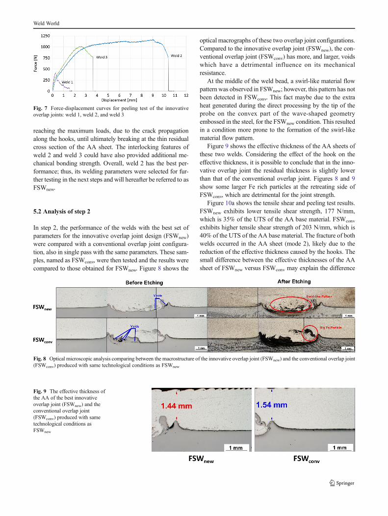
reaching the maximum loads, due to the crack propagationalong the hooks, until ultimately breaking at the thin residualcross section of the AA sheet. The interlocking features ofweld 2 and weld 3 could have also provided additional me-chanical bonding strength. Overall, weld 2 has the best per-formance; thus, its welding parameters were selected for fur-ther testing in the next steps and will hereafter be referred to asFSWnew.
5.2 Analysis of step 2
In step 2, the performance of the welds with the best set ofparameters for the innovative overlap joint design (FSWnew)were compared with a conventional overlap joint configura-tion, also in single pass with the same parameters. These sam-ples, named as FSWconv, were then tested and the results werecompared to those obtained for FSWnew. Figure 8 shows the
optical macrographs of these two overlap joint configurations.Compared to the innovative overlap joint (FSWnew), the con-ventional overlap joint (FSWconv) has more, and larger, voidswhich have a detrimental influence on its mechanicalresistance.
At the middle of the weld bead, a swirl-like material flowpattern was observed in FSWnew; however, this pattern has notbeen detected in FSWconv. This fact maybe due to the extraheat generated during the direct processing by the tip of theprobe on the convex part of the wave-shaped geometryembossed in the steel, for the FSWnew condition. This resultedin a condition more prone to the formation of the swirl-likematerial flow pattern.
Figure 9 shows the effective thickness of the AA sheets ofthese two welds. Considering the effect of the hook on theeffective thickness, it is possible to conclude that in the inno-vative overlap joint the residual thickness is slightly lowerthan that of the conventional overlap joint. Figures 8 and 9show some larger Fe rich particles at the retreating side ofFSWconv, which are detrimental for the joint strength.
Figure 10a shows the tensile shear and peeling test results.FSWnew exhibits lower tensile shear strength, 177 N/mm,which is 35% of the UTS of the AA base material. FSWconv
exhibits higher tensile shear strength of 203 N/mm, which is40% of the UTS of the AA base material. The fracture of bothwelds occurred in the AA sheet (mode 2), likely due to thereduction of the effective thickness caused by the hooks. Thesmall difference between the effective thicknesses of the AAsheet of FSWnew versus FSWconv may explain the difference
Fig. 7 Force-displacement curves for peeling test of the innovativeoverlap joints: weld 1, weld 2, and weld 3
Fig. 8 Optical microscopic analysis comparing between the macrostructure of the innovative overlap joint (FSWnew) and the conventional overlap joint(FSWconv) produced with same technological conditions as FSWnew
Fig. 9 The effective thickness ofthe AA of the best innovativeoverlap joint (FSWnew) and theconventional overlap joint(FSWconv) produced with sametechnological conditions asFSWnew
Weld World

in the maximum tensile shear strength between these twowelds.
Figure 10b presents the force-displacement history of theforce along the joint opening in the peeling test. Both weldingconditions exhibit a long propagation period under the maxi-mum load plateau. At the limit conditions, the fractures oc-curred in the AA base material. In contrast with the tensileshear test results, the maximum strength during the peelingtest of FSWnew is higher than that of FSWconv. This may bedue to the presence of larger Fe particles at the retreating sideof FSWconv. The large Fe particles act as imperfections,resulting in the reduction of the effective thickness of theAA base material.
5.3 Analysis of step 3
Figure 11 shows the optical macrographs of the single andmultipass FSWnew welds. The multipass welds exhibit fewervoids. This can be attributed to higher stirring efficiency,which improves material flow within the processing zone,eliminating the voids. The multipass welds also present fewermixture layers since they produce more heat and, therefore, agreater amount of steel is stirred and distributed into the pro-cessing zone of the AA sheet. On the bottom of Fig. 11, mi-crographs of positions 1 and 2 show details of the mixturelayers. The yellow curve highlights a hook-shapedinterlocking feature that is present in the weld with two passes.
Fig. 10 Comparative test results of FSWnew and FSWconv: a tensile sheartest results with fracture initiated from the hook (mode 2); b history of theresults for the peeling tests
Fig. 11 Optical microscopicanalysis comparing the single-pass weld with the multipasswelds (two passes and threepasses) for the innovative overlapjoint, where the multipass weldswere implemented with the samewelding parameters as FSWnew.Also included, micrographsemphasizing the accumulated Feparticles in position 1 (twopasses) and position 2 (threepasses)
Weld World
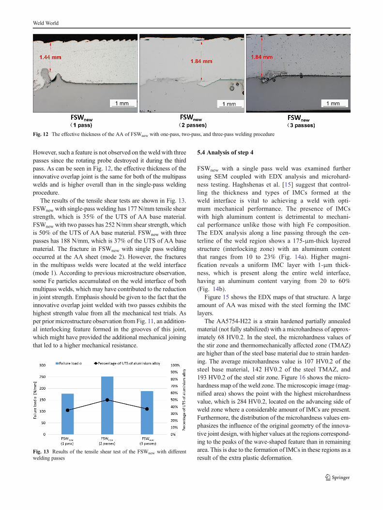
However, such a feature is not observed on the weld with threepasses since the rotating probe destroyed it during the thirdpass. As can be seen in Fig. 12, the effective thickness of theinnovative overlap joint is the same for both of the multipasswelds and is higher overall than in the single-pass weldingprocedure.
The results of the tensile shear tests are shown in Fig. 13.FSWnew with single-pass welding has 177 N/mm tensile shearstrength, which is 35% of the UTS of AA base material.FSWnew with two passes has 252 N/mm shear strength, whichis 50% of the UTS of AA base material. FSWnew with threepasses has 188 N/mm, which is 37% of the UTS of AA basematerial. The fracture in FSWnew with single pass weldingoccurred at the AA sheet (mode 2). However, the fracturesin the multipass welds were located at the weld interface(mode 1). According to previous microstructure observation,some Fe particles accumulated on the weld interface of bothmultipass welds, which may have contributed to the reductionin joint strength. Emphasis should be given to the fact that theinnovative overlap joint welded with two passes exhibits thehighest strength value from all the mechanical test trials. Asper prior microstructure observation from Fig. 11, an addition-al interlocking feature formed in the grooves of this joint,which might have provided the additional mechanical joiningthat led to a higher mechanical resistance.
5.4 Analysis of step 4
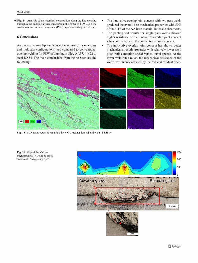
FSWnew with a single pass weld was examined furtherusing SEM coupled with EDX analysis and microhard-ness testing. Haghshenas et al. [15] suggest that control-ling the thickness and types of IMCs formed at theweld interface is vital to achieving a weld with opti-mum mechanical performance. The presence of IMCswith high aluminum content is detrimental to mechani-cal performance unlike those with high Fe composition.The EDX analysis along a line passing through the cen-terline of the weld region shows a 175-μm-thick layeredstructure (interlocking zone) with an aluminum contentthat ranges from 10 to 23% (Fig. 14a). Higher magni-fication reveals a uniform IMC layer with 1-μm thick-ness, which is present along the entire weld interface,having an aluminum content varying from 20 to 60%(Fig. 14b).
Figure 15 shows the EDX maps of that structure. A largeamount of AA was mixed with the steel forming the IMClayers.
The AA5754-H22 is a strain hardened partially annealedmaterial (not fully stabilized) with a microhardness of approx-imately 68 HV0.2. In the steel, the microhardness values ofthe stir zone and thermomechanically affected zone (TMAZ)are higher than of the steel base material due to strain harden-ing. The average microhardness value is 107 HV0.2 of thesteel base material, 142 HV0.2 of the steel TMAZ, and193 HV0.2 of the steel stir zone. Figure 16 shows the micro-hardness map of the weld zone. The microscopic image (mag-nified area) shows the point with the highest microhardnessvalue, which is 284 HV0.2, located on the advancing side ofweld zone where a considerable amount of IMCs are present.Furthermore, the distribution of the microhardness values em-phasizes the influence of the original geometry of the innova-tive joint design, with higher values at the regions correspond-ing to the peaks of the wave-shaped feature than in remainingarea. This is due to the formation of IMCs in these regions as aresult of the extra plastic deformation.
Fig. 12 The effective thickness of the AA of FSWnew with one-pass, two-pass, and three-pass welding procedure
Fig. 13 Results of the tensile shear test of the FSWnew with differentwelding passes
Weld World

Weld World
6 Conclusions
An innovative overlap joint concept was tested, in single-passand multipass configurations, and compared to conventionaloverlap welding for FSWof aluminum alloy AA5754-H22 tosteel DX54. The main conclusions from the research are thefollowing:
& The innovative overlap joint concept with two-pass weldsproduced the overall best mechanical properties with 50%of the UTS of the AA base material in tensile shear tests.
& The peeling test results for single pass welds showedhigher resistance of the innovative overlap joint conceptwhen compared with the conventional joint concept.
& The innovative overlap joint concept has shown bettermechanical strength properties with relatively lower weldpitch ratios (rotation speed versus travel speed). At thelower weld pitch ratios, the mechanical resistance of thewelds was mainly affected by the reduced residual effec-
�Fig. 14 Analysis of the chemical composition along the line crossingthrough a the multiple layered structures at the center of FSWnew; b thecontinuous intermetallic compound (IMC) layer across the joint interface
Fig. 15 EDX maps across the multiple layered structures located at the joint interface
Fig. 16 Map of the Vickersmicrohardness (HV0.2) on crosssection of FSWnew single pass
Weld World

tive thickness of the AA base material due to flow of thesteel into the aluminum (formation of the hook imperfec-tion), mainly at the flow side, i.e., the retreating side of thewelds.
& The innovative overlap joint with one pass produced alarger hook compared to the conventional overlap joint.The larger hook reduced the effective thickness of the AAsheet which considerably influenced the mechanical resis-tance of the welds.
& Voids were found at the Al-Fe interface, which can beobserved in the optical macrographs. The intermediatetravel speed conditions presented the lowest level of voidformation in terms of size and quantity. Multipass weldingincreased the material flow within the processing zone,which was helpful to eliminate the voids.
& The layered structure was dependent on the axial forgingforce. Higher axial forging force generated larger layeredstructures and higher internal pressure, which facilitatedthe consolidation of the joining. Moreover, the layeredstructure provided extra solid-state joining mechanisms,which increased the mechanical resistance of the welds.
& The optical micrographs showed that swirl-like patterns,and IMCs were preferentially formed at higher weld pitchratios as a result of higher heat input.
& The two-pass joint exhibited the best mechanical proper-ties compared with single-pass or three-pass welds, due tohigher stirring efficiency with a more uniform mechanicalinterlocking region.
& EDX analysis showed a uniform IMC layer with thicknessof 1 μm present along the entire weld interface, the alu-minum content of these IMCs ranged from 20 to 60%.
& The microhardness distribution closely follows the origi-nal geometry of the innovative overlap joint.
Open Access This article is distributed under the terms of the CreativeCommons At t r ibut ion 4 .0 In te rna t ional License (h t tp : / /creativecommons.org/licenses/by/4.0/), which permits unrestricted use,distribution, and reproduction in any medium, provided you give appro-priate credit to the original author(s) and the source, provide a link to theCreative Commons license, and indicate if changes were made.
References
1. Kenevisi MS, Khoie SM (2012) A study on the effect of bondingtime on the properties of Al7075 to Ti–6Al–4V diffusion bondedjoint. Mater Lett 76:144–146
2. Lee CJ, Kim JY, Lee SK, Ko DC, Kim BM (2010)Parametric study on mechanical clinching process for join-ing aluminum alloy and high-strength steel sheets. J MechSci Technol 24(1):123–126
3. Figner G, Vallant R, Weinberger T, Enzinger N, SchröttnerH, Paśič H (2009) Friction stir spot welds between alumin-ium and steel automotive sheets: influence of welding pa-rameters on mechanical properties and microstructure weldworld (2009) 53(1): R13-R23
4. Abe Y, Mori K, Kato T (2012) Joining of high strength steeland aluminium alloy sheets by mechanical clinching withdies for control of metal flow. J Mater Process Tech212(4):884–889
5. Dehghani M, Amadeh A, Mousavi SA (2013) Investigations on theeffects of friction stir welding parameters on intermetallic and de-fect formation in joining aluminum alloy to mild steel. MaterDesign 49:433–441
6. Thomas WM, Nicholas ED (1997) Friction stir welding for thetransportation industries. Mater Design 18(4–6):269–273
7. Leitao C, Leal RM, Rodrigues DM, Loureiro A, Vilaça P (2009)Mechanical behaviour of similar and dissimilar AA5182-H111 andAA6016-T4 thin friction stir welds. Mater Design 30(1):101–108
8. Kimapong K,Watanabe T (2004) Friction stir welding of aluminumalloy to steel. Weld J 83(10):277–282
9. Haghshenas M, Abdel-Gwad A, Omran AM, Gökçe B,Sahraeinejad S, Gerlich AP (2014) Friction stir weld assisted dif-fusion bonding of 5754 aluminum alloy to coated high strengthsteels. Mater Design 55:442–449
10. Uzun H, Dalle Donne C, Argagnotto A, Ghidini T, Gambaro C(2005) Friction stir welding of dissimilar Al 6013-T4 toX5CrNi18-10 stainless steel. Mater Design 26(1):41–46
11. Coelho RS, Kostka A, Sheikhi S, dos Santos J, Pyzalla AR (2008)Microstructure andmechanical properties of an AA6181-t4 alumin-ium alloy to HC340LA high strength steel friction stir overlap weld.Adv Eng Mater 10(10):961–972
12. Liu X, Lan S, Ni J (2014) Analysis of process parameters effects onfriction stir welding of dissimilar aluminum alloy to advanced highstrength steel. Mater Design 59(7):50–62
13. Sur Bang H, Seon Bang H, Hong Jeon G, Hyun Oh I, Seung Ro C(2012) Gas tungsten arc welding assisted hybrid friction stirwelding of dissimilar materials Al6061-T6 aluminum alloy andSTS304 stainless steel. Mater Design 37:48–55
14. Liu X, Lan S, Ni J (2015) Electrically assisted friction stir weldingfor joining Al 6061 to TRIP 780 steel. J Mater Process Tech 219:112–123
15. Chen ZW, Yazdanian S, Littlefair G (2012) Effects of toolpositioning on joint interface microstructure and fracturestrength of friction stir lap Al-to-steel welds. J Mater Sci48(6):2624–2634
16. Kimapong K, Watanabe T (2005) Lap joint of A5083 aluminumalloy and SS400 steel by friction stir welding. Mater Trans 46(4):835–841
17. Elrefaey A, Gouda M, Takahashi M, Ikeuchi K (2005)Characterization of aluminum/steel lap joint by friction stirwelding. J Mater Eng Perform 44(1):10–17
18. Cantin GMD, David SA, Thomas WM, Lara-Curzio E, Babu SS(2005) Sci Technol Weld Joi 10(3):269–280
Weld World


![FSW of aluminum AA5754 to steel DX54 with innovative ......joining, are well established in many car manufacturing compa-nies for joining dissimilar materials [ 2, 3]. Nonetheless,](https://img.dokumen.tips/doc/110x75/60b8621796d9c07cdf4e0d31/fsw-of-aluminum-aa5754-to-steel-dx54-with-innovative-joining-are-well-established.jpg)