Embed Size (px)
Citation preview
SERVICEMANUAL
Published in June 2009842JN111
2JNSM061Rev.1
FS-1128MFP
CAUTION
RISK OF EXPLOSION IF BATTERY IS REPLACED BY AN INCORRECT TYPE. DISPOSE OF USED BATTERIES ACCORDING TO THE INSTRUCTIONS.
It may be illegal to dispose of this battery into the municipal waste stream. Check with your local solid waste officials for details in your area for proper disposal.
ATTENTION
IL Y A UN RISQUE D’EXPLOSION SI LA BATTERIE EST REMPLACEE PAR UN MODELE DE TYPE INCORRECT. METTRE AU REBUT LES BATTERIES UTILISEES SELON LES INSTRUC-TIONS DONNEES.
Il peut être illégal de jeter les batteries dans des eaux d’égout municipales. Vérifiez avec les fonc-tionnaires municipaux de votre région pour les détails concernant des déchets solides et une mise au rebut appropriée.

Revision history
Revision Date Replaced pages Remarks
1 24 June 2009 1-3-37, 1-4-7, 1-4-8, 1-4-9, 1-4-11, 1-5-3, 1-5-21,1-5-22, 1-5-23, 1-5-24, 1-5-25, 1-5-26, 1-5-29,1-5-30, 1-5-49, 2-1-8, 2-2-2

This page is intentionally left blank.

Safety precautions
This booklet provides safety warnings and precautions for our service personnel to ensure the safety oftheir customers, their machines as well as themselves during maintenance activities. Service personnelare advised to read this booklet carefully to familiarize themselves with the warnings and precautionsdescribed here before engaging in maintenance activities.
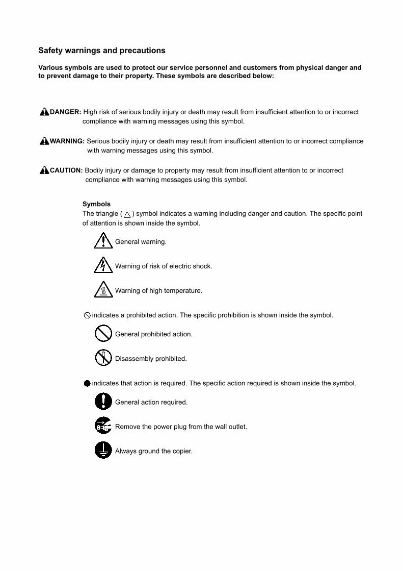
Safety warnings and precautions
Various symbols are used to protect our service personnel and customers from physical danger and to prevent damage to their property. These symbols are described below:
DANGER: High risk of serious bodily injury or death may result from insufficient attention to or incorrectcompliance with warning messages using this symbol.
WARNING: Serious bodily injury or death may result from insufficient attention to or incorrect compliancewith warning messages using this symbol.
CAUTION: Bodily injury or damage to property may result from insufficient attention to or incorrectcompliance with warning messages using this symbol.
SymbolsThe triangle ( ) symbol indicates a warning including danger and caution. The specific point of attention is shown inside the symbol.
General warning.
Warning of risk of electric shock.
Warning of high temperature.
indicates a prohibited action. The specific prohibition is shown inside the symbol.
General prohibited action.
Disassembly prohibited.
indicates that action is required. The specific action required is shown inside the symbol.
General action required.
Remove the power plug from the wall outlet.
Always ground the copier.
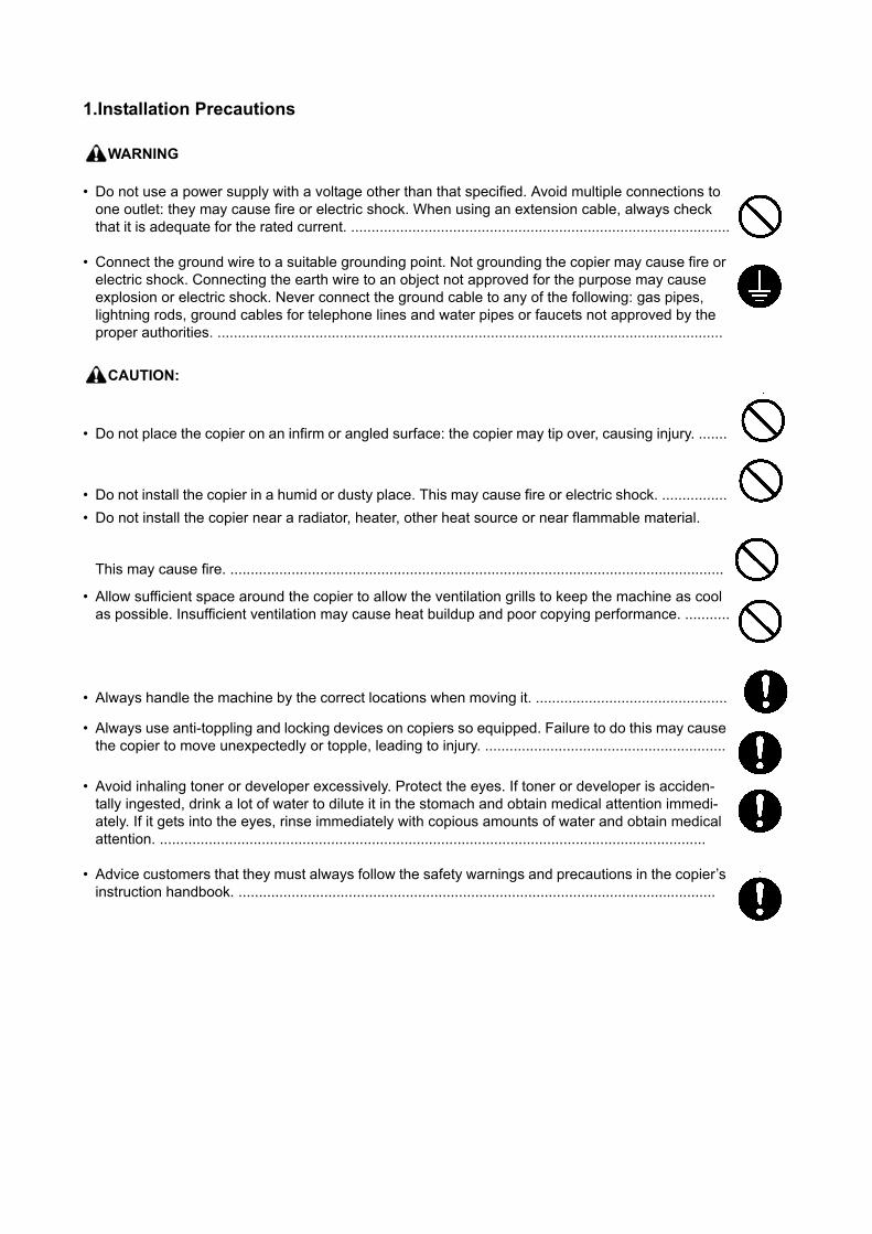
1.Installation Precautions
WARNING
• Do not use a power supply with a voltage other than that specified. Avoid multiple connections to one outlet: they may cause fire or electric shock. When using an extension cable, always check that it is adequate for the rated current. .............................................................................................
• Connect the ground wire to a suitable grounding point. Not grounding the copier may cause fire or electric shock. Connecting the earth wire to an object not approved for the purpose may cause explosion or electric shock. Never connect the ground cable to any of the following: gas pipes, lightning rods, ground cables for telephone lines and water pipes or faucets not approved by the proper authorities. ............................................................................................................................
CAUTION:
• Do not place the copier on an infirm or angled surface: the copier may tip over, causing injury. .......
• Do not install the copier in a humid or dusty place. This may cause fire or electric shock. ................• Do not install the copier near a radiator, heater, other heat source or near flammable material.
This may cause fire. .........................................................................................................................
• Allow sufficient space around the copier to allow the ventilation grills to keep the machine as cool as possible. Insufficient ventilation may cause heat buildup and poor copying performance. ...........
• Always handle the machine by the correct locations when moving it. ...............................................
• Always use anti-toppling and locking devices on copiers so equipped. Failure to do this may cause the copier to move unexpectedly or topple, leading to injury. ...........................................................
• Avoid inhaling toner or developer excessively. Protect the eyes. If toner or developer is acciden-tally ingested, drink a lot of water to dilute it in the stomach and obtain medical attention immedi-ately. If it gets into the eyes, rinse immediately with copious amounts of water and obtain medical attention. ......................................................................................................................................
• Advice customers that they must always follow the safety warnings and precautions in the copier’s instruction handbook. .....................................................................................................................
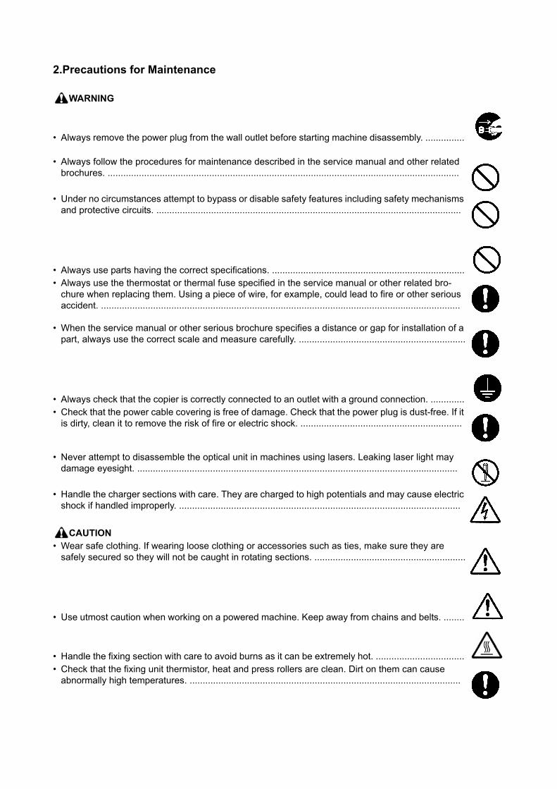
2.Precautions for Maintenance
WARNING
• Always remove the power plug from the wall outlet before starting machine disassembly. ...............
• Always follow the procedures for maintenance described in the service manual and other related brochures. .......................................................................................................................................
• Under no circumstances attempt to bypass or disable safety features including safety mechanisms and protective circuits. .....................................................................................................................
• Always use parts having the correct specifications. ..........................................................................• Always use the thermostat or thermal fuse specified in the service manual or other related bro-
chure when replacing them. Using a piece of wire, for example, could lead to fire or other serious accident. ..........................................................................................................................................
• When the service manual or other serious brochure specifies a distance or gap for installation of a part, always use the correct scale and measure carefully. ................................................................
• Always check that the copier is correctly connected to an outlet with a ground connection. .............• Check that the power cable covering is free of damage. Check that the power plug is dust-free. If it
is dirty, clean it to remove the risk of fire or electric shock. ..............................................................
• Never attempt to disassemble the optical unit in machines using lasers. Leaking laser light may damage eyesight. ...........................................................................................................................
• Handle the charger sections with care. They are charged to high potentials and may cause electric shock if handled improperly. ............................................................................................................
CAUTION• Wear safe clothing. If wearing loose clothing or accessories such as ties, make sure they are
safely secured so they will not be caught in rotating sections. ..........................................................
• Use utmost caution when working on a powered machine. Keep away from chains and belts. ........
• Handle the fixing section with care to avoid burns as it can be extremely hot. ..................................• Check that the fixing unit thermistor, heat and press rollers are clean. Dirt on them can cause
abnormally high temperatures. ........................................................................................................
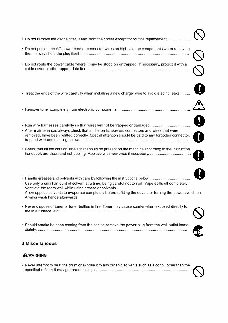
• Do not remove the ozone filter, if any, from the copier except for routine replacement. ....................
• Do not pull on the AC power cord or connector wires on high-voltage components when removing them; always hold the plug itself. .....................................................................................................
• Do not route the power cable where it may be stood on or trapped. If necessary, protect it with a cable cover or other appropriate item. .............................................................................................
• Treat the ends of the wire carefully when installing a new charger wire to avoid electric leaks. ........
• Remove toner completely from electronic components. ...................................................................
• Run wire harnesses carefully so that wires will not be trapped or damaged. ....................................• After maintenance, always check that all the parts, screws, connectors and wires that were
removed, have been refitted correctly. Special attention should be paid to any forgotten connector, trapped wire and missing screws. ...................................................................................................
• Check that all the caution labels that should be present on the machine according to the instruction handbook are clean and not peeling. Replace with new ones if necessary. ......................................
• Handle greases and solvents with care by following the instructions below: .....................................Use only a small amount of solvent at a time, being careful not to spill. Wipe spills off completely.Ventilate the room well while using grease or solvents.Allow applied solvents to evaporate completely before refitting the covers or turning the power switch on.Always wash hands afterwards.
• Never dispose of toner or toner bottles in fire. Toner may cause sparks when exposed directly to fire in a furnace, etc. .......................................................................................................................
• Should smoke be seen coming from the copier, remove the power plug from the wall outlet imme-diately. ............................................................................................................................................
3.Miscellaneous
WARNING
• Never attempt to heat the drum or expose it to any organic solvents such as alcohol, other than the specified refiner; it may generate toxic gas. .....................................................................................

This page is intentionally left blank.
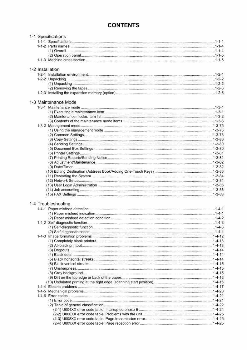
CONTENTS
1-1 Specifications1-1-1 Specifications..........................................................................................................................................1-1-11-1-2 Parts names............................................................................................................................................1-1-4
(1) Overall ...............................................................................................................................................1-1-4(2) Operation panel.................................................................................................................................1-1-5
1-1-3 Machine cross section ............................................................................................................................1-1-6
1-2 Installation1-2-1 Installation environment ..........................................................................................................................1-2-11-2-2 Unpacking ...............................................................................................................................................1-2-2
(1) Unpacking .........................................................................................................................................1-2-2(2) Removing the tapes ..........................................................................................................................1-2-3
1-2-3 Installing the expansion memory (option) ...............................................................................................1-2-6
1-3 Maintenance Mode1-3-1 Maintenance mode .................................................................................................................................1-3-1
(1) Executing a maintenance item ..........................................................................................................1-3-1(2) Maintenance modes item list.............................................................................................................1-3-2(3) Contents of the maintenance mode items.........................................................................................1-3-6
1-3-2 Management mode ...............................................................................................................................1-3-75(1) Using the management mode .........................................................................................................1-3-75(2) Common Settings............................................................................................................................1-3-76(3) Copy Settings..................................................................................................................................1-3-80(4) Sending Settings .............................................................................................................................1-3-80(5) Document Box Settings...................................................................................................................1-3-80(6) Printer Settings................................................................................................................................1-3-81(7) Printing Reports/Sending Notice .....................................................................................................1-3-81(8) Adjustment/Maintenance.................................................................................................................1-3-82(9) Date/Timer.......................................................................................................................................1-3-82
(10) Editing Destination (Address Book/Adding One-Touch Keys) ........................................................1-3-83(11) Restarting the System.....................................................................................................................1-3-84(12) Network Setup.................................................................................................................................1-3-84(13) User Login Administration ...............................................................................................................1-3-86(14) Job accounting ................................................................................................................................1-3-86(15) FAX Settings ...................................................................................................................................1-3-88
1-4 Troubleshooting1-4-1 Paper misfeed detection .........................................................................................................................1-4-1
(1) Paper misfeed indication ...................................................................................................................1-4-1(2) Paper misfeed detection condition ....................................................................................................1-4-2
1-4-2 Self-diagnostic function...........................................................................................................................1-4-3(1) Self-diagnostic function .....................................................................................................................1-4-3(2) Self diagnostic codes ........................................................................................................................1-4-4
1-4-3 Image formation problems ....................................................................................................................1-4-12(1) Completely blank printout................................................................................................................1-4-13(2) All-black printout..............................................................................................................................1-4-13(3) Dropouts..........................................................................................................................................1-4-14(4) Black dots........................................................................................................................................1-4-14(5) Black horizontal streaks. .................................................................................................................1-4-14(6) Black vertical streaks.......................................................................................................................1-4-15(7) Unsharpness. ..................................................................................................................................1-4-15(8) Gray background.............................................................................................................................1-4-15(9) Dirt on the top edge or back of the paper........................................................................................1-4-16
(10) Undulated printing at the right edge (scanning start position). ........................................................1-4-161-4-4 Electric problems ..................................................................................................................................1-4-171-4-5 Mechanical problems ............................................................................................................................1-4-201-4-6 Error codes ...........................................................................................................................................1-4-21
(1) Error code........................................................................................................................................1-4-21(2) Table of general classification .........................................................................................................1-4-22
(2-1) U004XX error code table: Interrupted phase B .......................................................................1-4-24 (2-2) U006XX error code table: Problems with the unit ...................................................................1-4-25 (2-3) U008XX error code table: Page transmission error.................................................................1-4-25 (2-4) U009XX error code table: Page reception error ......................................................................1-4-25
(2-5) U010XX error code table: G3 transmission.............................................................................1-4-26 (2-6) U011XX error code table: G3 reception ..................................................................................1-4-28 (2-7) U017XX error code table: V.34 transmission ..........................................................................1-4-30 (2-8) U018XX error code table: V.34 reception................................................................................1-4-30 (2-9) U023XX error code table: Relay command abnormal reception .............................................1-4-30
(2-10) U044XX error code table: Encrypted transmission .................................................................1-4-301-4-7 Send error code ....................................................................................................................................1-4-31
(1) Scan to SMB error codes ................................................................................................................1-4-31(2) Scan to FTP error codes .................................................................................................................1-4-32(3) Scan to E-mail error codes..............................................................................................................1-4-33(4) Network Twain error codes .............................................................................................................1-4-34(5) Software trouble error codes ...........................................................................................................1-4-34
1-5 Assembly and Disassembly1-5-1 Precautions for assembly and disassembly............................................................................................1-5-1
(1) Precautions .......................................................................................................................................1-5-1(2) Drum..................................................................................................................................................1-5-1(3) Toner .................................................................................................................................................1-5-1(4) How to tell a genuine Kyocera Mita toner container..........................................................................1-5-2
1-5-2 Outer covers ...........................................................................................................................................1-5-3(1) Detaching and refitting the left cover and right cover ........................................................................1-5-3
1-5-3 Paper feed section ..................................................................................................................................1-5-6(1) Detaching and refitting the paper feed assembly (paper feed roller and pickup roller) .....................1-5-6(2) Detaching and refitting the retard roller assembly.............................................................................1-5-8(3) Detaching and refitting the MP paper feed roller.............................................................................1-5-10(4) Note on removing and Installing the upper registration roller and lower registration roller .............1-5-12
1-5-4 Optical section ......................................................................................................................................1-5-13(1) Detaching and refitting the DP ........................................................................................................1-5-13(2) Detaching and refitting the scanner unit..........................................................................................1-5-14(3) Detaching and refitting the laser scanner unit (LSU).......................................................................1-5-17(4) Replacing the image scanner unit (ISU)..........................................................................................1-5-21(5) Detaching and refitting the exposure lamp and inverter PWB.........................................................1-5-27
1-5-5 Developing section................................................................................................................................1-5-29(1) Detaching and refitting the developing unit .....................................................................................1-5-29
1-5-6 Drum section.........................................................................................................................................1-5-30(1) Detaching and refitting the drum unit ..............................................................................................1-5-30(2) Detaching and refitting the main charger unit..................................................................................1-5-31
1-5-7 Transfer/separation section ..................................................................................................................1-5-32(1) Detaching and refitting the transfer roller ........................................................................................1-5-32
1-5-8 Fuser section ........................................................................................................................................1-5-34(1) Detaching and refitting the fuser unit...............................................................................................1-5-34(2) Switching the fuser pressure ...........................................................................................................1-5-38
1-5-9 PWBs ....................................................................................................................................................1-5-39(1) Detaching and refitting the control PWB .........................................................................................1-5-39(2) Detaching and refitting the power source PWB...............................................................................1-5-42(3) Detaching and refitting the high voltage PWB.................................................................................1-5-45(4) Detaching and refitting the scanner PWB .......................................................................................1-5-49(5) Detaching and refitting the FAX PWB .............................................................................................1-5-50
1-5-10 Others ...................................................................................................................................................1-5-51(1) Detaching and refitting the main motor ...........................................................................................1-5-51(2) Direction of installing the left cooling fan motor, right cooling fan motor and power source
fan motor .........................................................................................................................................1-5-521-5-11 DP.........................................................................................................................................................1-5-53
1-6 Requirements on PWB Replacement1-6-1 Upgrading the firmware...........................................................................................................................1-6-11-6-2 Remarks on control PWB replacement...................................................................................................1-6-2
2-1 Mechanical Construction2-1-1 Paper feed/conveying section.................................................................................................................2-1-1
(1) Cassette paper feed section..............................................................................................................2-1-1(2) MP tray paper feed section ...............................................................................................................2-1-2(3) Paper conveying section ...................................................................................................................2-1-3
2-1-2 Drum section...........................................................................................................................................2-1-4(1) Drum section .....................................................................................................................................2-1-4
(2) Main charger unit...............................................................................................................................2-1-52-1-3 Optical section ........................................................................................................................................2-1-6
(1) Scanner unit ......................................................................................................................................2-1-6(2) Image scanner unit (ISU) ..................................................................................................................2-1-7(3) Laser scanner unit.............................................................................................................................2-1-9
2-1-4 Developing section................................................................................................................................2-1-112-1-5 Transfer/separation section ..................................................................................................................2-1-122-1-6 Cleaning section ...................................................................................................................................2-1-132-1-7 Fuser section ........................................................................................................................................2-1-142-1-8 Paper exit section .................................................................................................................................2-1-162-1-9 Duplex/conveying section .....................................................................................................................2-1-18
2-1-10 DP section.............................................................................................................................................2-1-19
2-2 Electrical Parts Layout2-2-1 Electrical parts layout..............................................................................................................................2-2-1
(1) PWBs ................................................................................................................................................2-2-1(2) Switches and sensors .......................................................................................................................2-2-3(3) Other electrical components..............................................................................................................2-2-4(4) DP .....................................................................................................................................................2-2-5
2-3 Operation of the PWBs2-3-1 Power source PWB.................................................................................................................................2-3-12-3-2 Control PWB ...........................................................................................................................................2-3-32-3-3 Scanner PWB .........................................................................................................................................2-3-92-3-4 DP driver PWB......................................................................................................................................2-3-12
2-4 Appendixes2-4-1 Appendixes .............................................................................................................................................2-4-1
(1) Wiring diagram ..................................................................................................................................2-4-1(2) Repetitive defects gauge...................................................................................................................2-4-3(3) Maintenance parts list .......................................................................................................................2-4-4

This page is intentionally left blank.
2JN
1-1 Specifications
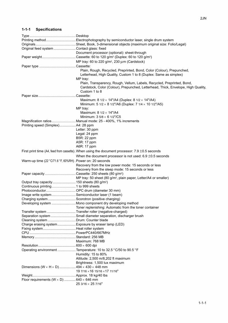
1-1-1 SpecificationsType ................................................DesktopPrinting method...............................Electrophotography by semiconductor laser, single drum systemOriginals..........................................Sheet, Book, 3-dimensional objects (maximum original size: Folio/Legal)Original feed system .......................Contact glass: fixed
Document processor (optional): sheet-throughPaper weight...................................Cassette: 60 to 120 g/m2 (Duplex: 60 to 120 g/m2)
MP tray: 60 to 220 g/m2, 230 µm (Cardstock)Paper type ......................................Cassette:
Plain, Rough, Recycled, Preprinted, Bond, Color (Colour), Prepunched, Letterhead, High Quality, Custom 1 to 8 (Duplex: Same as simplex)
MP tray: Plain, Transparency, Rough, Vellum, Labels, Recycled, Preprinted, Bond,Cardstock, Color (Colour), Prepunched, Letterhead, Thick, Envelope, High Quality,Custom 1 to 8
Paper size.......................................Cassette: Maximum: 8 1/2 × 14"/A4 (Duplex: 8 1/2 × 14"/A4)Minimum: 5 1/2 × 8 1/2"/A6 (Duplex: 7 1/4 × 10 1/2"/A5)
MP tray: Maximum: 8 1/2 × 14"/A4Minimum: 3 5/8 × 6 1/2"/C5
Magnification ratios.........................Manual mode: 25 - 400%, 1% incrementsPrinting speed (Simplex).................A4: 28 ppm
Letter: 30 ppmLegal: 24 ppmB5R: 22 ppmA5R: 17 ppmA6R: 17 ppm
First print time (A4, feed from cassette) .When using the document processor: 7.9 ±0.5 secondsWhen the document processor is not used: 6.9 ±0.5 seconds
Warm-up time (22 °C/71.6 °F, 60%RH) .Power on: 20 secondsRecovery from the low power mode: 15 seconds or lessRecovery from the sleep mode: 15 seconds or less
Paper capacity ................................Cassette: 250 sheets (80 g/m2)MP tray: 50 sheet (80 g/m2, plain paper, Letter/A4 or smaller)
Output tray capacity........................150 sheets (80 g/m2)Continuous printing.........................1 to 999 sheetsPhotoconductor...............................OPC drum (diameter 30 mm)Image write system.........................Semiconductor laser (1 beam)Charging system.............................Scorotron (positive charging)Developing system .........................Mono component dry developing method
Toner replenishing: Automatic from the toner containerTransfer system ..............................Transfer roller (negative-charged)Separation system ..........................Small diameter separation, discharger brushCleaning system .............................Drum: Counter bladeCharge erasing system...................Exposure by eraser lamp (LED)Fixing system..................................Heat roller systemCPU ................................................PowerPC440/667MHzMemory...........................................Standard: 256 MB
Maximum: 768 MBResolution.......................................600 × 600 dpiOperating environment ...................Temperature: 10 to 32.5 °C/50 to 90.5 °F
Humidity: 15 to 80%Altitude: 2,500 m/8,202 ft maximumBrightness: 1,500 lux maximum
Dimensions (W × H × D) .................494 × 430 × 448 mm19 7/16 ×16 15/16 ×17 11/16"
Weight.............................................Approx. 18 kg/40 lbsFloor requirements (W × D) ............640 × 646 mm
25 3/16 × 25 7/16"
1-1-1
2JN
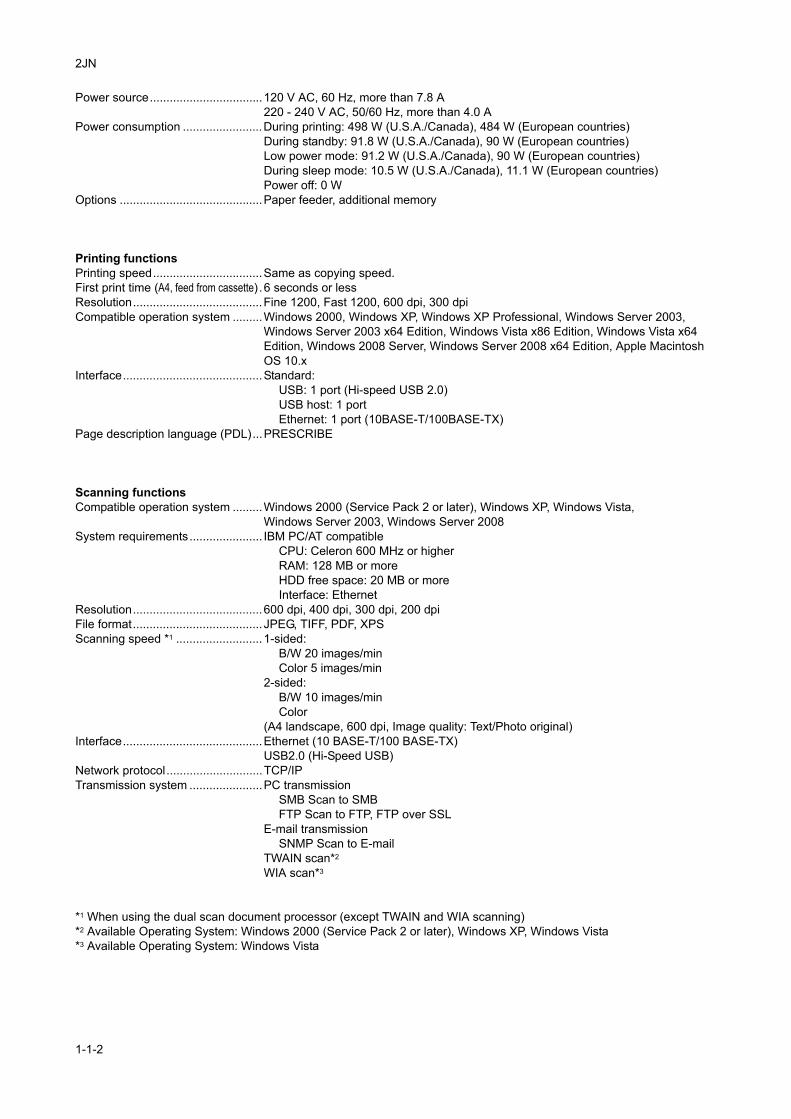
Power source..................................120 V AC, 60 Hz, more than 7.8 A220 - 240 V AC, 50/60 Hz, more than 4.0 A
Power consumption ........................During printing: 498 W (U.S.A./Canada), 484 W (European countries)During standby: 91.8 W (U.S.A./Canada), 90 W (European countries)Low power mode: 91.2 W (U.S.A./Canada), 90 W (European countries)During sleep mode: 10.5 W (U.S.A./Canada), 11.1 W (European countries)Power off: 0 W
Options ...........................................Paper feeder, additional memory
Printing functionsPrinting speed.................................Same as copying speed.First print time (A4, feed from cassette) .6 seconds or lessResolution.......................................Fine 1200, Fast 1200, 600 dpi, 300 dpiCompatible operation system .........Windows 2000, Windows XP, Windows XP Professional, Windows Server 2003,
Windows Server 2003 x64 Edition, Windows Vista x86 Edition, Windows Vista x64 Edition, Windows 2008 Server, Windows Server 2008 x64 Edition, Apple Macintosh OS 10.x
Interface..........................................Standard:USB: 1 port (Hi-speed USB 2.0)USB host: 1 portEthernet: 1 port (10BASE-T/100BASE-TX)
Page description language (PDL)...PRESCRIBE
Scanning functionsCompatible operation system .........Windows 2000 (Service Pack 2 or later), Windows XP, Windows Vista,
Windows Server 2003, Windows Server 2008System requirements...................... IBM PC/AT compatible
CPU: Celeron 600 MHz or higherRAM: 128 MB or moreHDD free space: 20 MB or moreInterface: Ethernet
Resolution.......................................600 dpi, 400 dpi, 300 dpi, 200 dpiFile format.......................................JPEG, TIFF, PDF, XPSScanning speed *1 ..........................1-sided:
B/W 20 images/minColor 5 images/min
2-sided:B/W 10 images/minColor
(A4 landscape, 600 dpi, Image quality: Text/Photo original)Interface..........................................Ethernet (10 BASE-T/100 BASE-TX)
USB2.0 (Hi-Speed USB)Network protocol.............................TCP/IPTransmission system ......................PC transmission
SMB Scan to SMBFTP Scan to FTP, FTP over SSL
E-mail transmissionSNMP Scan to E-mail
TWAIN scan*2 WIA scan*3
*1 When using the dual scan document processor (except TWAIN and WIA scanning)*2 Available Operating System: Windows 2000 (Service Pack 2 or later), Windows XP, Windows Vista*3 Available Operating System: Windows Vista
1-1-2
2JN
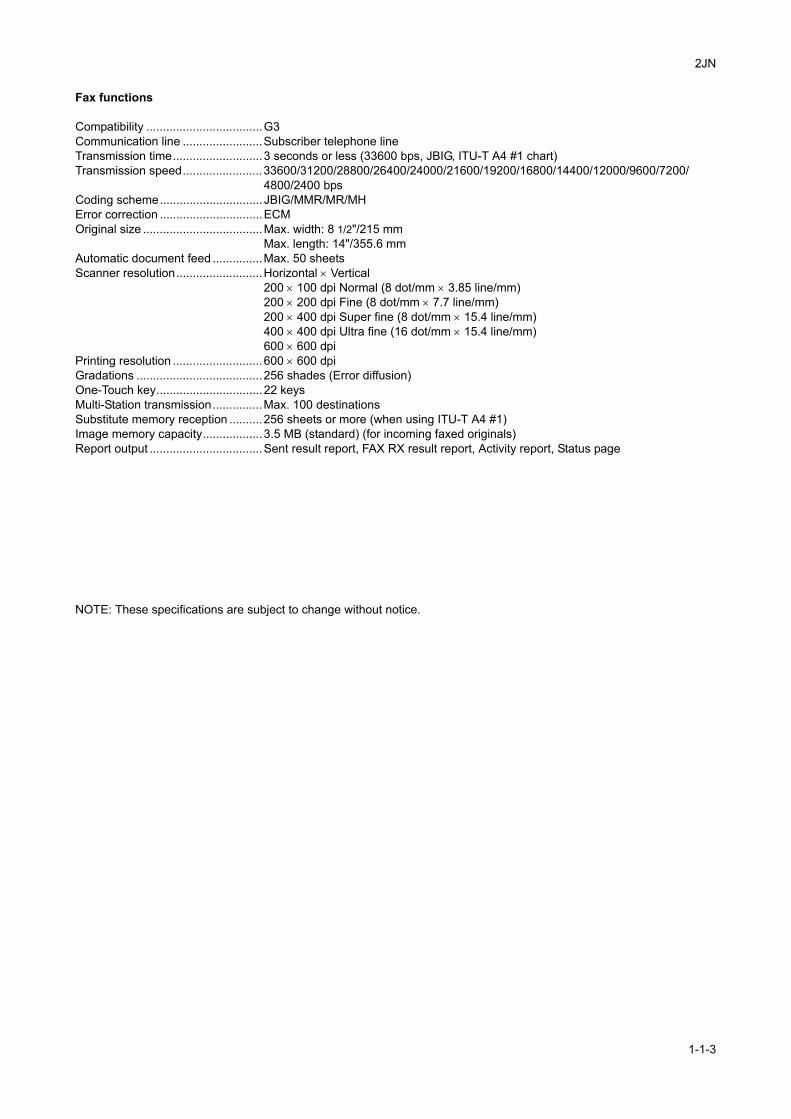
Fax functions
Compatibility ...................................G3Communication line ........................Subscriber telephone lineTransmission time...........................3 seconds or less (33600 bps, JBIG, ITU-T A4 #1 chart)Transmission speed........................33600/31200/28800/26400/24000/21600/19200/16800/14400/12000/9600/7200/
4800/2400 bpsCoding scheme...............................JBIG/MMR/MR/MHError correction ...............................ECMOriginal size ....................................Max. width: 8 1/2"/215 mm
Max. length: 14"/355.6 mmAutomatic document feed ...............Max. 50 sheetsScanner resolution..........................Horizontal × Vertical
200 × 100 dpi Normal (8 dot/mm × 3.85 line/mm)200 × 200 dpi Fine (8 dot/mm × 7.7 line/mm)200 × 400 dpi Super fine (8 dot/mm × 15.4 line/mm)400 × 400 dpi Ultra fine (16 dot/mm × 15.4 line/mm)600 × 600 dpi
Printing resolution ...........................600 × 600 dpiGradations ......................................256 shades (Error diffusion)One-Touch key................................22 keysMulti-Station transmission...............Max. 100 destinationsSubstitute memory reception ..........256 sheets or more (when using ITU-T A4 #1)Image memory capacity..................3.5 MB (standard) (for incoming faxed originals)Report output ..................................Sent result report, FAX RX result report, Activity report, Status page
NOTE: These specifications are subject to change without notice.
1-1-3
2JN
1-1-2 Parts names
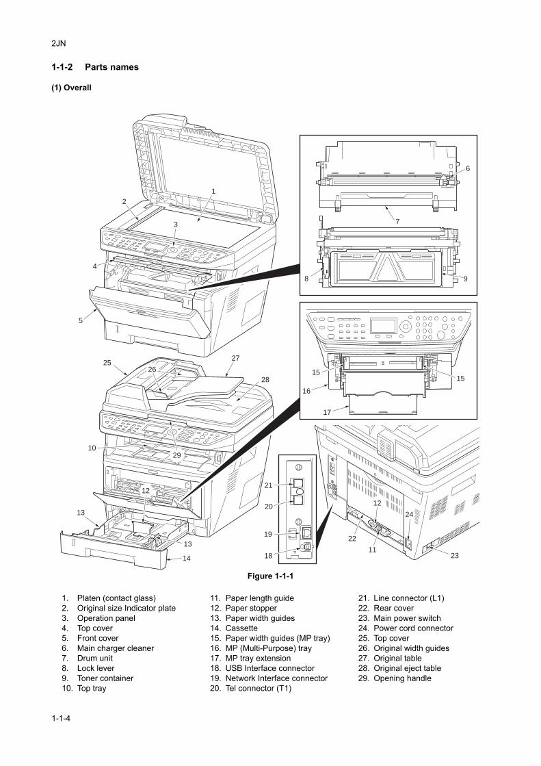
(1) Overall
Figure 1-1-1
25
6
8
7
1
2
4
5
9
10
12
11
13
13
17
18
22
24
23
19
20
21
16
1515
14
3
12
26
27
28
29
1. Platen (contact glass)2. Original size Indicator plate3. Operation panel4. Top cover5. Front cover6. Main charger cleaner7. Drum unit8. Lock lever9. Toner container10. Top tray
11. Paper length guide12. Paper stopper13. Paper width guides14. Cassette15. Paper width guides (MP tray)16. MP (Multi-Purpose) tray17. MP tray extension18. USB Interface connector19. Network Interface connector20. Tel connector (T1)
21. Line connector (L1)22. Rear cover23. Main power switch24. Power cord connector25. Top cover26. Original width guides27. Original table28. Original eject table29. Opening handle
1-1-4
2JN
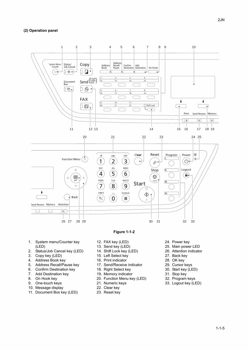
(2) Operation panel
Figure 1-1-2
1
11 12 13 14 15 16 17 18 19
20 21 22 23 24 25
29 30 31 32 33282726
32 4 5 6 7 9 108
1. System menu/Counter key (LED)
2. Status/Job Cancel key (LED)3. Copy key (LED)4. Address Book key5. Address Recall/Pause key6. Confirm Destination key7. Add Destination key8. On Hook key9. One-touch keys10. Message display11. Document Box key (LED)
12. FAX key (LED)13. Send key (LED)14. Shift Lock key (LED)15. Left Select key16. Print indicator17. Send/Receive indicator18. Right Select key19. Memory indicator20. Function Menu key (LED)21. Numeric keys22. Clear key23. Reset key
24. Power key25. Main power LED26. Attention indicator27. Back key28. OK key29. Cursor keys30. Start key (LED)31. Stop key32. Program keys33. Logout key (LED)
1-1-5
2JN
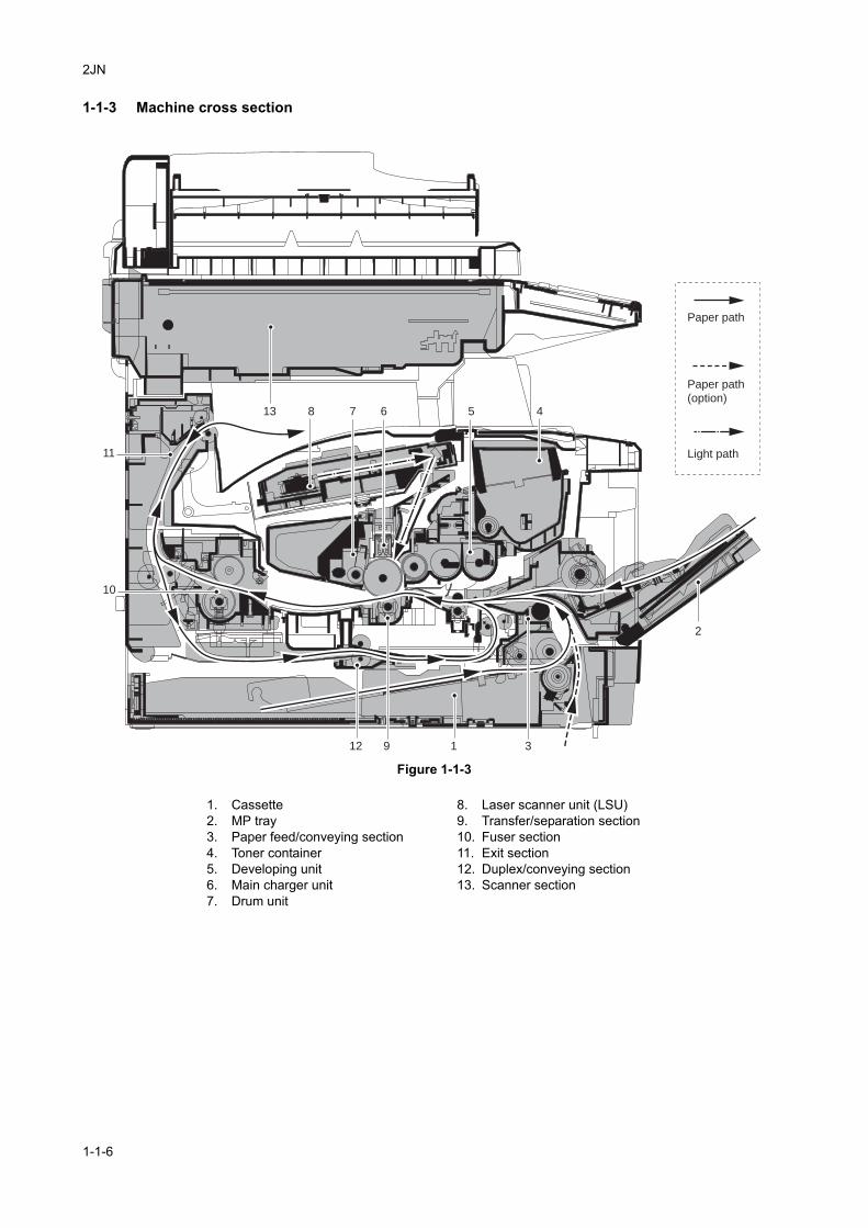
1-1-3 Machine cross section
Figure 1-1-3
13
1912 3
2
45678
10
11
Paper path
Paper path
(option)
Light path
1. Cassette2. MP tray3. Paper feed/conveying section4. Toner container5. Developing unit6. Main charger unit7. Drum unit
8. Laser scanner unit (LSU)9. Transfer/separation section10. Fuser section11. Exit section12. Duplex/conveying section13. Scanner section
1-1-6
2JN
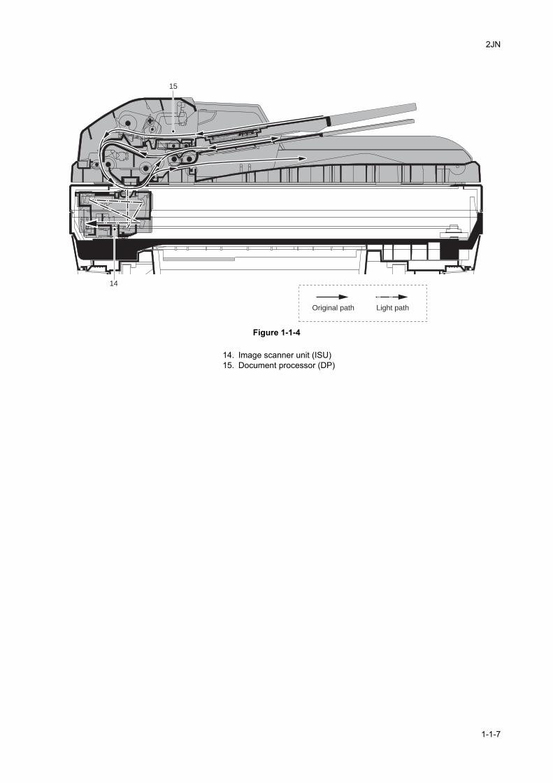
Figure 1-1-4
14
15
Original path Light path
14. Image scanner unit (ISU)15. Document processor (DP)
1-1-7

2JN
This page is intentionally left blank.
1-1-8
2JN
1-2 Installation
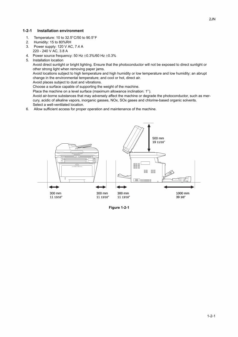
1-2-1 Installation environment1. Temperature: 10 to 32.5°C/50 to 90.5°F2. Humidity: 15 to 80%RH3. Power supply: 120 V AC, 7.4 A
220 - 240 V AC, 3.8 A4. Power source frequency: 50 Hz ±0.3%/60 Hz ±0.3%5. Installation location
Avoid direct sunlight or bright lighting. Ensure that the photoconductor will not be exposed to direct sunlight or other strong light when removing paper jams.Avoid locations subject to high temperature and high humidity or low temperature and low humidity; an abrupt change in the environmental temperature; and cool or hot, direct air.Avoid places subject to dust and vibrations.Choose a surface capable of supporting the weight of the machine.Place the machine on a level surface (maximum allowance inclination: 1°).Avoid air-borne substances that may adversely affect the machine or degrade the photoconductor, such as mer-cury, acidic of alkaline vapors, inorganic gasses, NOx, SOx gases and chlorine-based organic solvents.Select a well-ventilated location.
6. Allow sufficient access for proper operation and maintenance of the machine.
Figure 1-2-1
300 mm
11 13/16"
300 mm
11 13/16"
300 mm
11 13/16"
300 mm
11 13/16"
300 mm
11 13/16"
300 mm
11 13/16"
500 mm
19 11/16"
500 mm
19 11/16"
1000 mm
39 3/8"
1000 mm
39 3/8"
1-2-1
2JN
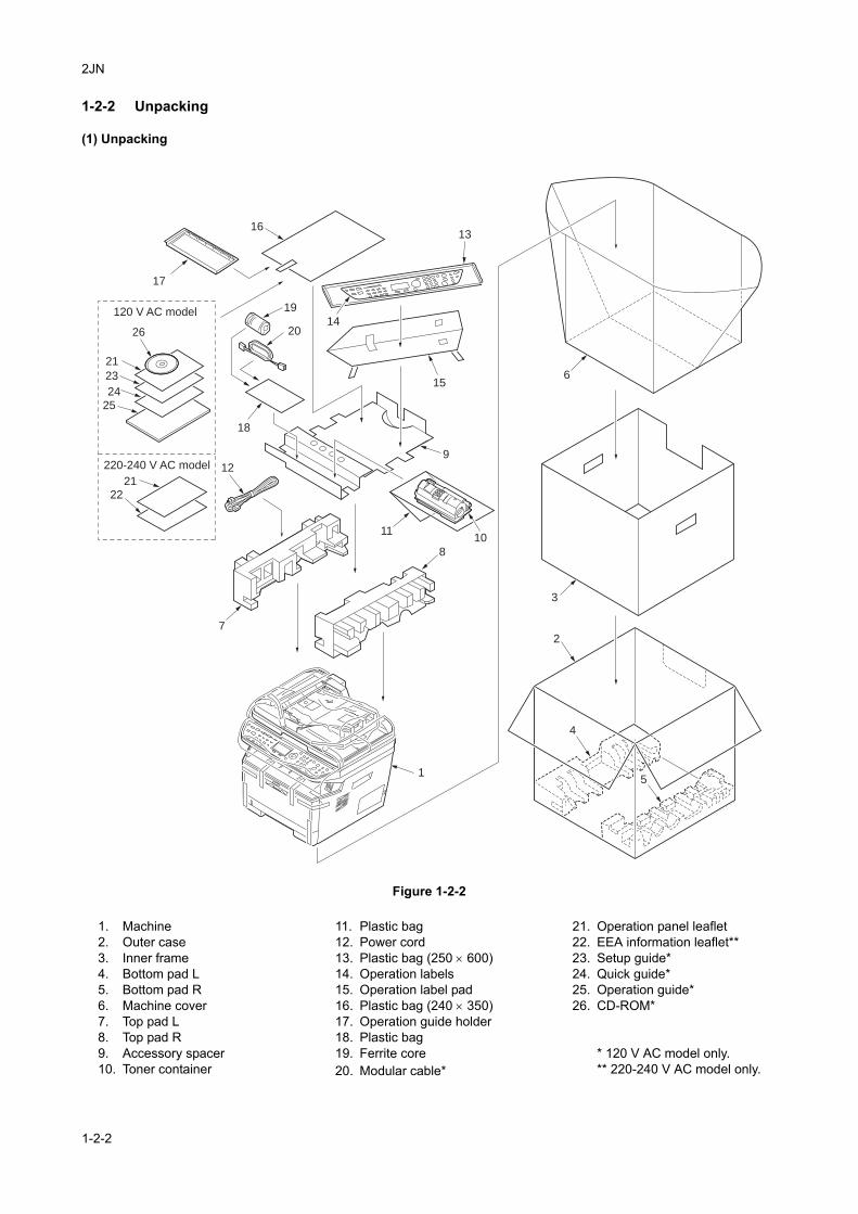
1-2-2 Unpacking
(1) Unpacking
Figure 1-2-2
4
2
15
3
6
8
1011
12
13
14
16
17
18
19
20
15
7
9
21
2122
23
24
25
26
120 V AC model
220-240 V AC model
1. Machine2. Outer case3. Inner frame4. Bottom pad L5. Bottom pad R6. Machine cover7. Top pad L8. Top pad R9. Accessory spacer10. Toner container
11. Plastic bag12. Power cord13. Plastic bag (250 × 600)14. Operation labels15. Operation label pad16. Plastic bag (240 × 350)17. Operation guide holder18. Plastic bag19. Ferrite core20. Modular cable*
21. Operation panel leaflet22. EEA information leaflet**23. Setup guide*24. Quick guide*25. Operation guide*26. CD-ROM*
* 120 V AC model only.** 220-240 V AC model only.
1-2-2
2JN
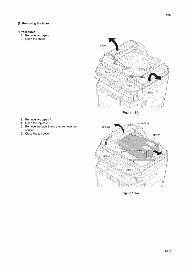
(2) Removing the tapes
<Procedure>1. Remove two tapes.2. Open the sheet.
Figure 1-2-3
3. Remove two tapes A.4. Open the top cover.5. Remove the tape B and then remove the
spacer.6. Close the top cover.
Figure 1-2-4
Sheet
Tape
Tape
Sheet
Tape B
Tape A
Top cover
Tape A
Spacer
1-2-3
2JN
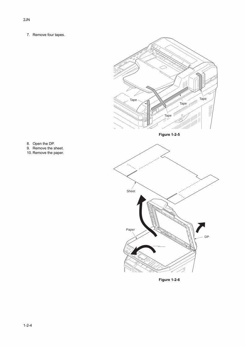
7. Remove four tapes.
Figure 1-2-5
8. Open the DP.9. Remove the sheet.10. Remove the paper.
Figure 1-2-6
Tape
Tape
Tape
Tape
DP
Sheet
Paper
1-2-4
2JN
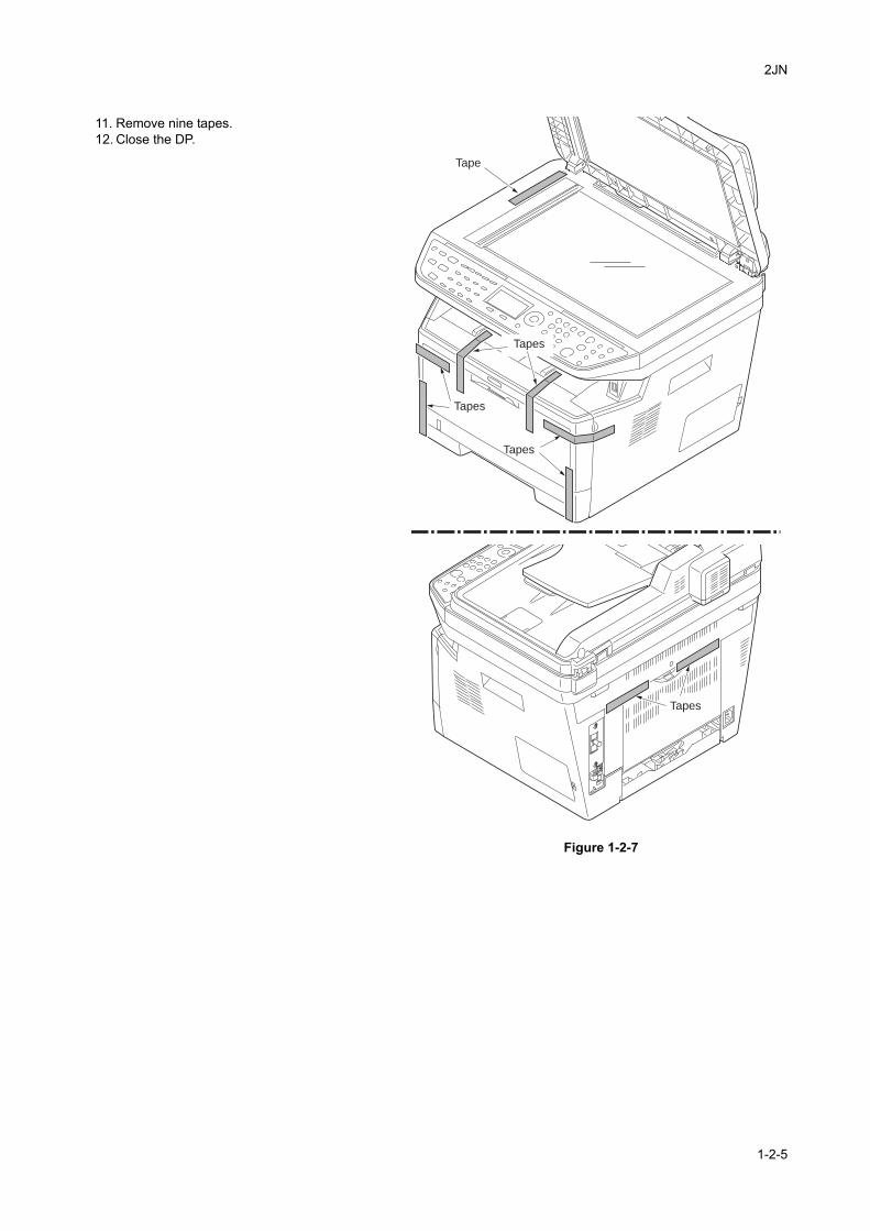
11. Remove nine tapes.12. Close the DP.
Figure 1-2-7
Tape
Tapes
Tapes
Tapes
Tapes
1-2-5
2JN
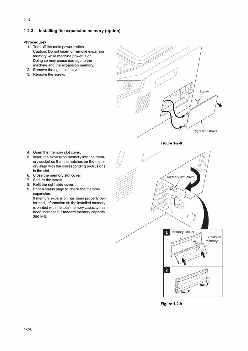
1-2-3 Installing the expansion memory (option)
<Procedure>1. Turn off the main power switch.
Caution: Do not insert or remove expansion memory while machine power is on.Doing so may cause damage to the machine and the expansion memory.
2. Remove the right side cover.3. Remove the screw.
Figure 1-2-8
4. Open the memory slot cover.5. Insert the expansion memory into the mem-
ory socket so that the notches on the mem-ory align with the corresponding protrusions in the slot.
6. Close the memory slot cover.7. Secure the screw.8. Refit the right side cover.9. Print a status page to check the memory
expansion.If memory expansion has been properly per-formed, information on the installed memory is printed with the total memory capacity has been increased. Standard memory capacity 256 MB.
Figure 1-2-9
Right side cover
Screw
1
2
Expansion
memory
Memory socket
Memory slot cover
1-2-6
2JN
1-3 Maintenance Mode
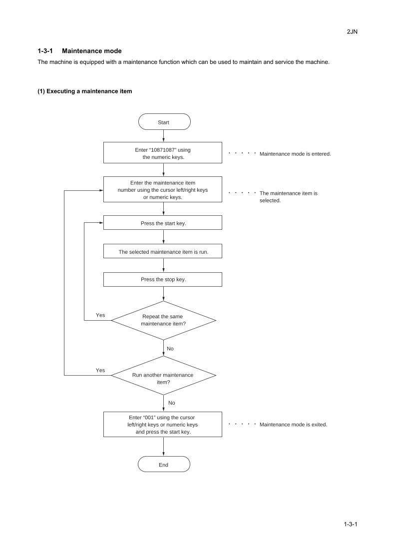
1-3-1 Maintenance modeThe machine is equipped with a maintenance function which can be used to maintain and service the machine.
(1) Executing a maintenance item
Enter “10871087” using
the numeric keys.
Enter “001” using the cursor
left/right keys or numeric keys
and press the start key.
Enter the maintenance item
number using the cursor left/right keys
or numeric keys.
The selected maintenance item is run.
Press the stop key.
Press the start key.
Start
End
Maintenance mode is entered.
The maintenance item is
selected.
Maintenance mode is exited.
Repeat the same
maintenance item?
Run another maintenance
item?
No
No
Yes
Yes
1-3-1
2JN
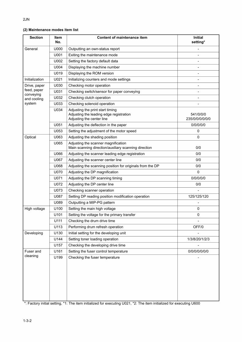
(2) Maintenance modes item list
Section ItemNo.
Content of maintenance item Initialsetting*
General U000 Outputting an own-status report -
U001 Exiting the maintenance mode -
U002 Setting the factory default data -
U004 Displaying the machine number -
U019 Displaying the ROM version -
Initialization U021 Initializing counters and mode settings -
Drive, paper feed, paper conveying and cooling system
U030 Checking motor operation -
U031 Checking switch/sensor for paper conveying -
U032 Checking clutch operation -
U033 Checking solenoid operation -
U034 Adjusting the print start timingAdjusting the leading edge registrationAdjusting the center line
541/0/0/0235/0/0/0/0/0/0
U051 Adjusting the deflection in the paper 0/0/0/0/0
U053 Setting the adjustment of the motor speed 0
Optical U063 Adjusting the shading position 0
U065 Adjusting the scanner magnificationMain scanning direction/auxiliary scanning direction 0/0
U066 Adjusting the scanner leading edge registration 0/0
U067 Adjusting the scanner center line 0/0
U068 Adjusting the scanning position for originals from the DP 0/0
U070 Adjusting the DP magnification 0
U071 Adjusting the DP scanning timing 0/0/0/0/0
U072 Adjusting the DP center line 0/0
U073 Checking scanner operation -
U087 Setting DP reading position modification operation 125/125/120
U089 Outputting a MIP-PG pattern -
High voltage U100 Setting the main high voltage 0
U101 Setting the voltage for the primary transfer 0
U111 Checking the drum drive time -
U113 Performing drum refresh operation OFF/0
Developing U130 Initial setting for the developing unit -
U144 Setting toner loading operation 1/3/8/20/1/2/3
U157 Checking the developing drive time -
Fuser and cleaning
U161 Setting the fuser control temperature 0/0/0/0/0/0/0
U199 Checking the fuser temperature -
*: Factory initial setting, *1: The item initialized for executing U021, *2: The item initialized for executing U600
1-3-2
2JN
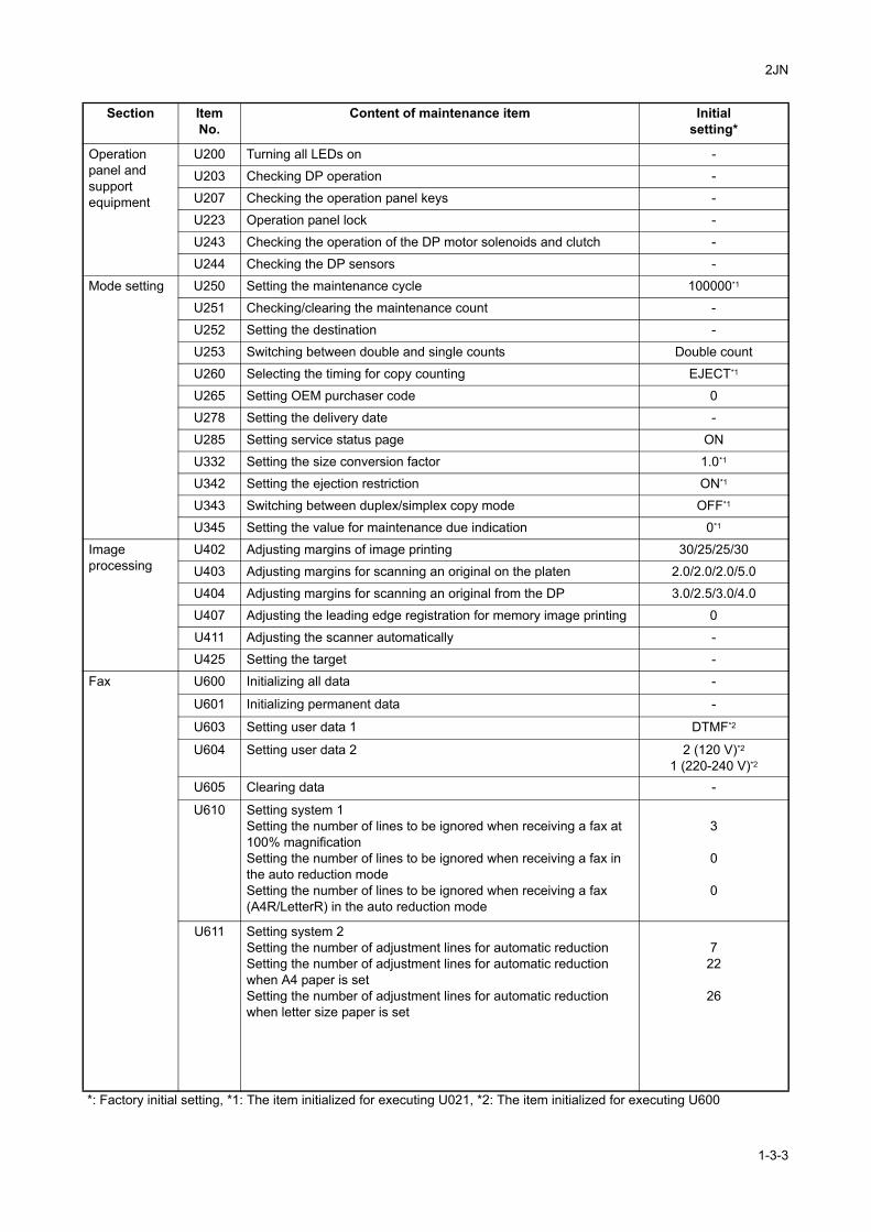
Operationpanel andsupportequipment
U200 Turning all LEDs on -
U203 Checking DP operation -
U207 Checking the operation panel keys -
U223 Operation panel lock -
U243 Checking the operation of the DP motor solenoids and clutch -
U244 Checking the DP sensors -
Mode setting U250 Setting the maintenance cycle 100000*1
U251 Checking/clearing the maintenance count -
U252 Setting the destination -
U253 Switching between double and single counts Double count
U260 Selecting the timing for copy counting EJECT*1
U265 Setting OEM purchaser code 0
U278 Setting the delivery date -
U285 Setting service status page ON
U332 Setting the size conversion factor 1.0*1
U342 Setting the ejection restriction ON*1
U343 Switching between duplex/simplex copy mode OFF*1
U345 Setting the value for maintenance due indication 0*1
Imageprocessing
U402 Adjusting margins of image printing 30/25/25/30
U403 Adjusting margins for scanning an original on the platen 2.0/2.0/2.0/5.0
U404 Adjusting margins for scanning an original from the DP 3.0/2.5/3.0/4.0
U407 Adjusting the leading edge registration for memory image printing 0
U411 Adjusting the scanner automatically -
U425 Setting the target -
Fax U600 Initializing all data -
U601 Initializing permanent data -
U603 Setting user data 1 DTMF*2
U604 Setting user data 2 2 (120 V)*2
1 (220-240 V)*2
U605 Clearing data -
U610 Setting system 1Setting the number of lines to be ignored when receiving a fax at 100% magnificationSetting the number of lines to be ignored when receiving a fax in the auto reduction modeSetting the number of lines to be ignored when receiving a fax (A4R/LetterR) in the auto reduction mode
3
0
0
U611 Setting system 2Setting the number of adjustment lines for automatic reductionSetting the number of adjustment lines for automatic reduction when A4 paper is setSetting the number of adjustment lines for automatic reduction when letter size paper is set
722
26
Section ItemNo.
Content of maintenance item Initialsetting*
*: Factory initial setting, *1: The item initialized for executing U021, *2: The item initialized for executing U600
1-3-3
2JN
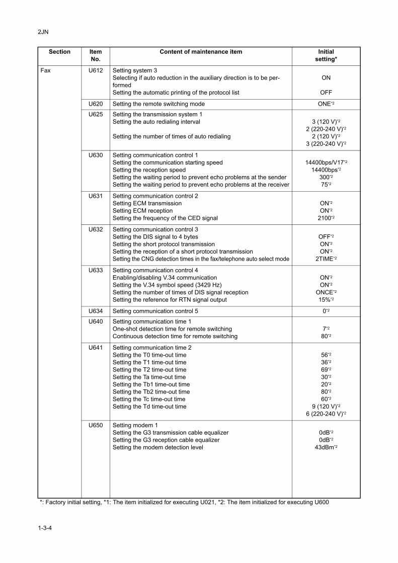
Fax U612 Setting system 3Selecting if auto reduction in the auxiliary direction is to be per-formedSetting the automatic printing of the protocol list
ON
OFF
U620 Setting the remote switching mode ONE*2
U625 Setting the transmission system 1Setting the auto redialing interval
Setting the number of times of auto redialing
3 (120 V)*2
2 (220-240 V)*2
2 (120 V)*2
3 (220-240 V)*2
U630 Setting communication control 1Setting the communication starting speedSetting the reception speedSetting the waiting period to prevent echo problems at the senderSetting the waiting period to prevent echo problems at the receiver
14400bps/V17*2
14400bps*2
300*2
75*2
U631 Setting communication control 2Setting ECM transmissionSetting ECM receptionSetting the frequency of the CED signal
ON*2
ON*2
2100*2
U632 Setting communication control 3Setting the DIS signal to 4 bytesSetting the short protocol transmissionSetting the reception of a short protocol transmissionSetting the CNG detection times in the fax/telephone auto select mode
OFF*2
ON*2
ON*2
2TIME*2
U633 Setting communication control 4Enabling/disabling V.34 communicationSetting the V.34 symbol speed (3429 Hz)Setting the number of times of DIS signal receptionSetting the reference for RTN signal output
ON*2
ON*2
ONCE*2
15%*2
U634 Setting communication control 5 0*2
U640 Setting communication time 1One-shot detection time for remote switchingContinuous detection time for remote switching
7*2
80*2
U641 Setting communication time 2Setting the T0 time-out timeSetting the T1 time-out timeSetting the T2 time-out timeSetting the Ta time-out timeSetting the Tb1 time-out timeSetting the Tb2 time-out timeSetting the Tc time-out timeSetting the Td time-out time
56*2
36*2
69*2
30*2
20*2
80*2
60*2
9 (120 V)*2
6 (220-240 V)*2
U650 Setting modem 1Setting the G3 transmission cable equalizerSetting the G3 reception cable equalizerSetting the modem detection level
0dB*2
0dB*2
43dBm*2
Section ItemNo.
Content of maintenance item Initialsetting*
*: Factory initial setting, *1: The item initialized for executing U021, *2: The item initialized for executing U600
1-3-4
2JN
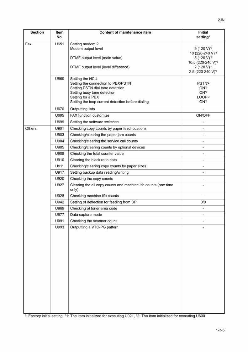
Fax U651 Setting modem 2Modem output level
DTMF output level (main value)
DTMF output level (level difference)
9 (120 V)*2
10 (220-240 V)*2
5 (120 V)*2
10.5 (220-240 V)*2
2 (120 V)*2
2.5 (220-240 V)*2
U660 Setting the NCUSetting the connection to PBX/PSTNSetting PSTN dial tone detectionSetting busy tone detectionSetting for a PBXSetting the loop current detection before dialing
PSTN*2
ON*2
ON*2
LOOP*2
ON*2
U670 Outputting lists -
U695 FAX function customize ON/OFF
U699 Setting the software switches -
Others U901 Checking copy counts by paper feed locations -
U903 Checking/clearing the paper jam counts -
U904 Checking/clearing the service call counts -
U905 Checking/clearing counts by optional devices -
U908 Checking the total counter value -
U910 Clearing the black ratio data -
U911 Checking/clearing copy counts by paper sizes -
U917 Setting backup data reading/writing -
U920 Checking the copy counts -
U927 Clearing the all copy counts and machine life counts (one time only)
-
U928 Checking machine life counts -
U942 Setting of deflection for feeding from DP 0/0
U969 Checking of toner area code -
U977 Data capture mode -
U991 Checking the scanner count -
U993 Outputting a VTC-PG pattern -
Section ItemNo.
Content of maintenance item Initialsetting*
*: Factory initial setting, *1: The item initialized for executing U021, *2: The item initialized for executing U600
1-3-5
2JN
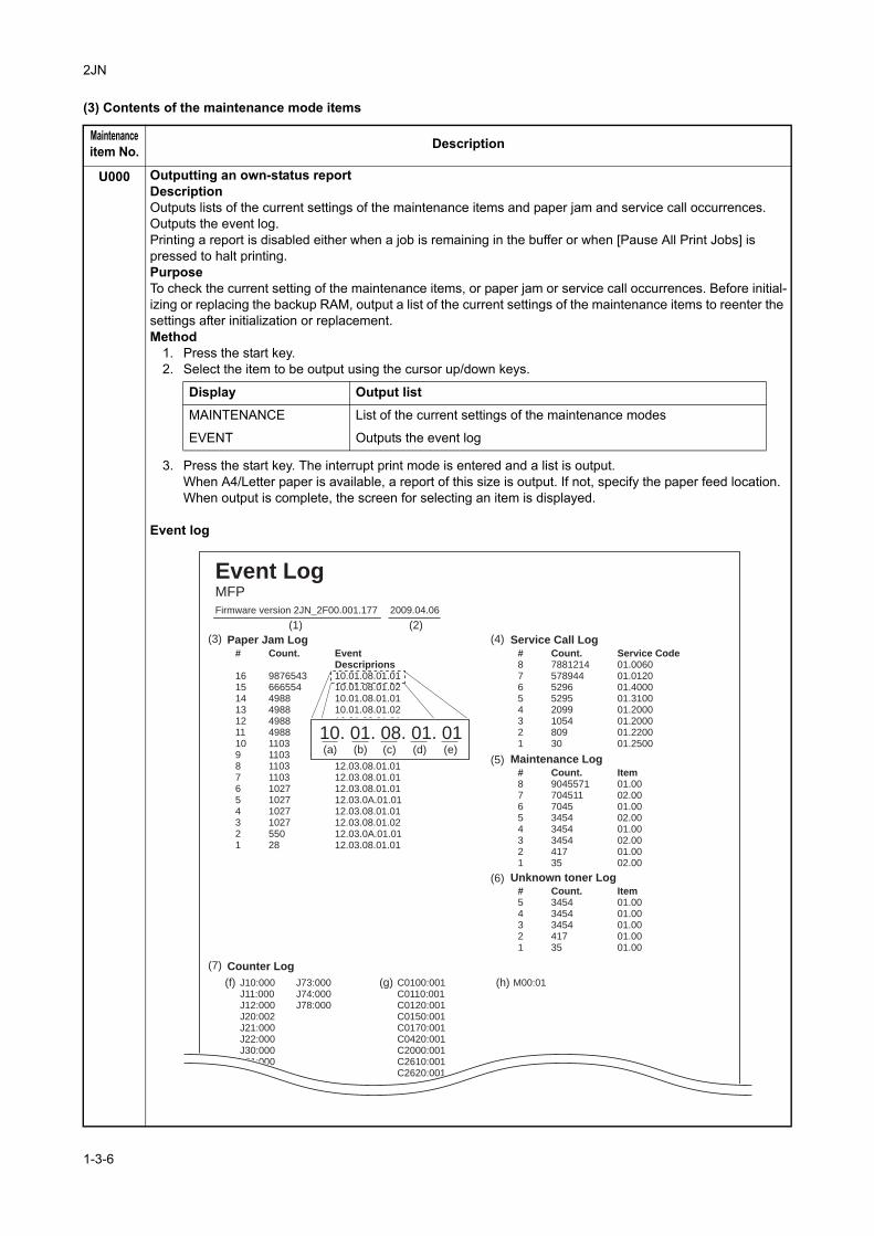
(3) Contents of the maintenance mode items
Maintenanceitem No. Description
U000 Outputting an own-status reportDescriptionOutputs lists of the current settings of the maintenance items and paper jam and service call occurrences. Outputs the event log.Printing a report is disabled either when a job is remaining in the buffer or when [Pause All Print Jobs] is pressed to halt printing.PurposeTo check the current setting of the maintenance items, or paper jam or service call occurrences. Before initial-izing or replacing the backup RAM, output a list of the current settings of the maintenance items to reenter the settings after initialization or replacement.Method
1. Press the start key.2. Select the item to be output using the cursor up/down keys.
3. Press the start key. The interrupt print mode is entered and a list is output.When A4/Letter paper is available, a report of this size is output. If not, specify the paper feed location.When output is complete, the screen for selecting an item is displayed.
Event log
Display Output list
MAINTENANCE List of the current settings of the maintenance modes
EVENT Outputs the event log
Firmware version 2JN_2F00.001.177
Paper Jam Log
Counter Log
2009.04.06
J10:000J11:000J12:000J20:002J21:000J22:000J30:000J31:000
J73:000J74:000J78:000
C0100:001C0110:001C0120:001C0150:001C0170:001C0420:001C2000:001C2610:001C2620:001
M00:01
#
16151413121110987654321
Count.
987654366655449884988498849881103110311031103102710271027102755028
EventDescriprions10.01.08.01.0110.01.08.01.0210.01.08.01.0110.01.08.01.0210.01.08.01.0110.01.08.01.0210.01.08.01.0110.01.08.01.0112.03.08.01.0112.03.08.01.0112.03.08.01.0112.03.0A.01.0112.03.08.01.0112.03.08.01.0212.03.0A.01.0112.03.08.01.01
Service Call Log#87654321
Count.7881214578944529652952099105480930
Service Code01.006001.012001.400001.310001.200001.200001.220001.2500
Maintenance Log#87654321
Count.9045571704511704534543454345441735
Item01.0002.0001.0002.0001.0002.0001.0002.00
Unknown toner Log#54321
Count.34543454345441735
Item01.0001.0001.0001.0001.00
Event LogMFP
(f) (g) (h)
(a) (b) (c) (d) (e)
10. 01. 08. 01. 01
(1)
(3)
(7)
(4)
(5)
(6)
(2)
1-3-6
2JN
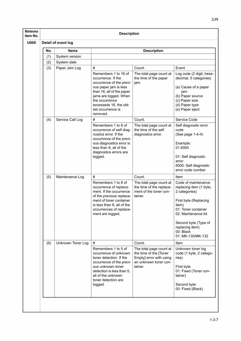
U000 Detail of event log
Maintenanceitem No. Description
No. Items Description(1) System version(2) System date(3) Paper Jam Log # Count. Event
Remembers 1 to 16 of occurrence. If the occurrence of the previ-ous paper jam is less than 16, all of the paper jams are logged. When the occurrence excesseds 16, the old-est occurrence is removed.
The total page count at the time of the paper jam.
Log code (2 digit, hexa-decimal, 5 categories)
(a) Cause of a paper jam
(b) Paper source(c) Paper size(d) Paper type(e) Paper eject
(4) Service Call Log # Count. Service CodeRemembers 1 to 8 of occurrence of self diag-nostics error. If the occurrence of the previ-ous diagnostics error is less than 8, all of the diagnostics errors are logged.
The total page count at the time of the self diagnostics error.
Self diagnostic error code(See page 1-4-4)
Example:01.6000
01: Self diagnostic error6000: Self diagnostic error code number
(5) Maintenance Log # Count. ItemRemembers 1 to 8 of occurrence of replace-ment. If the occurrence of the previous replace-ment of toner container is less than 8, all of the occurrences of replace-ment are logged.
The total page count at the time of the replace-ment of the toner con-tainer.
Code of maintenance replacing item (1 byte, 2 categories)
First byte (Replacing item)01: Toner container02: Maintenance kit
Second byte (Type of replacing item)00: Black01: MK-130/MK-132
(6) Unknown Toner Log # Count. ItemRemembers 1 to 5 of occurrence of unknown toner detection. If the occurrence of the previ-ous unknown toner detection is less than 5, all of the unknown toner detection are logged.
The total page count at the time of the [Toner Empty] error with using an unknown toner con-tainer.
Unknown toner log code (1 byte, 2 catego-ries)
First byte01: Fixed (Toner con-tainer)
Second byte00: Fixed (Black)
1-3-7
2JN
U000
CompletionPress the stop key. The screen for selecting a maintenance item No. is displayed.
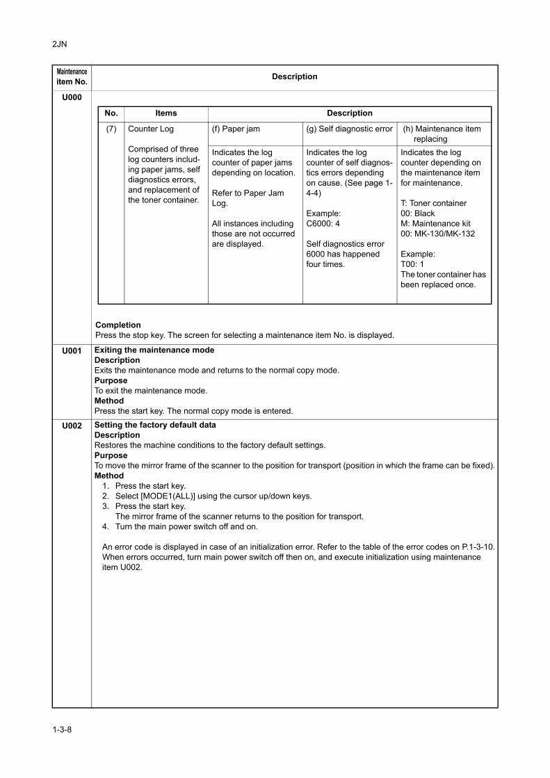
U001 Exiting the maintenance modeDescriptionExits the maintenance mode and returns to the normal copy mode. PurposeTo exit the maintenance mode.MethodPress the start key. The normal copy mode is entered.
U002 Setting the factory default dataDescriptionRestores the machine conditions to the factory default settings.PurposeTo move the mirror frame of the scanner to the position for transport (position in which the frame can be fixed).Method
1. Press the start key.2. Select [MODE1(ALL)] using the cursor up/down keys.3. Press the start key.
The mirror frame of the scanner returns to the position for transport.4. Turn the main power switch off and on.
An error code is displayed in case of an initialization error. Refer to the table of the error codes on P.1-3-10.When errors occurred, turn main power switch off then on, and execute initialization using maintenance item U002.
Maintenanceitem No. Description
No. Items Description
(7) Counter Log
Comprised of three log counters includ-ing paper jams, self diagnostics errors, and replacement of the toner container.
(f) Paper jam (g) Self diagnostic error (h) Maintenance item replacing
Indicates the log counter of paper jams depending on location.
Refer to Paper Jam Log.
All instances including those are not occurred are displayed.
Indicates the log counter of self diagnos-tics errors depending on cause. (See page 1-4-4)
Example: C6000: 4
Self diagnostics error 6000 has happened four times.
Indicates the log counter depending on the maintenance item for maintenance.
T: Toner container00: BlackM: Maintenance kit00: MK-130/MK-132
Example:T00: 1The toner container has been replaced once.
1-3-8
2JN
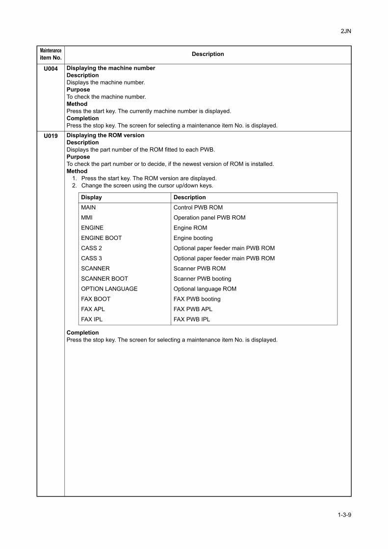
U004 Displaying the machine numberDescriptionDisplays the machine number.PurposeTo check the machine number.MethodPress the start key. The currently machine number is displayed.CompletionPress the stop key. The screen for selecting a maintenance item No. is displayed.
U019 Displaying the ROM versionDescriptionDisplays the part number of the ROM fitted to each PWB.PurposeTo check the part number or to decide, if the newest version of ROM is installed.Method
1. Press the start key. The ROM version are displayed.2. Change the screen using the cursor up/down keys.
Completion Press the stop key. The screen for selecting a maintenance item No. is displayed.
Maintenanceitem No. Description
Display Description
MAIN Control PWB ROM
MMI Operation panel PWB ROM
ENGINE Engine ROM
ENGINE BOOT Engine booting
CASS 2 Optional paper feeder main PWB ROM
CASS 3 Optional paper feeder main PWB ROM
SCANNER Scanner PWB ROM
SCANNER BOOT Scanner PWB booting
OPTION LANGUAGE Optional language ROM
FAX BOOT FAX PWB booting
FAX APL FAX PWB APL
FAX IPL FAX PWB IPL
1-3-9
2JN
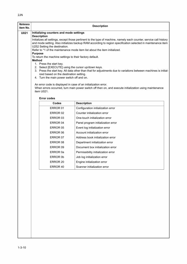
U021 Initializing counters and mode settingsDescriptionInitializes all settings, except those pertinent to the type of machine, namely each counter, service call history and mode setting. Also initializes backup RAM according to region specification selected in maintenance item U252 Setting the destination.Refer to *1 of the maintenance mode item list about the item initialized.PurposeTo return the machine settings to their factory default.Method
1. Press the start key.2. Select [EXECUTE] using the cursor up/down keys.3. Press the start key. All data other than that for adjustments due to variations between machines is initial-
ized based on the destination setting.4. Turn the main power switch off and on.
An error code is displayed in case of an initialization error.When errors occurred, turn main power switch off then on, and execute initialization using maintenance item U021.
Error codes
Maintenanceitem No. Description
Codes Description
ERROR 01 Configuration initialization error
ERROR 02 Counter initialization error
ERROR 03 One-touch initialization error
ERROR 04 Panel program initialization error
ERROR 05 Event log initialization error
ERROR 06 Account initialization error
ERROR 07 Address book initialization error
ERROR 08 Department initialization error
ERROR 09 Document box initialization error
ERROR 0a Permissibility initialization error
ERROR 0b Job log initialization error
ERROR 20 Engine initialization error
ERROR 40 Scanner initialization error
1-3-10
2JN
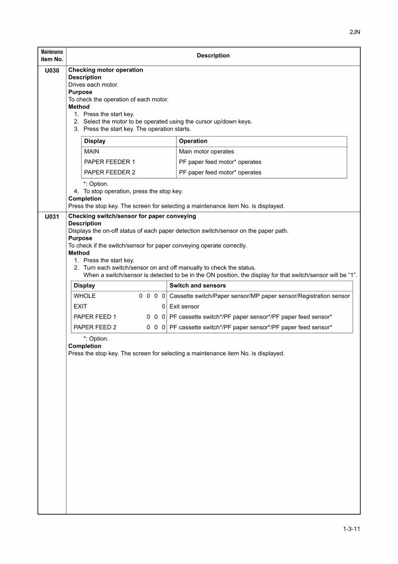
U030 Checking motor operationDescriptionDrives each motor.PurposeTo check the operation of each motor.Method
1. Press the start key.2. Select the motor to be operated using the cursor up/down keys.3. Press the start key. The operation starts.
*: Option.4. To stop operation, press the stop key.
Completion Press the stop key. The screen for selecting a maintenance item No. is displayed.
U031 Checking switch/sensor for paper conveyingDescriptionDisplays the on-off status of each paper detection switch/sensor on the paper path.PurposeTo check if the switch/sensor for paper conveying operate correctly.Method
1. Press the start key.2. Turn each switch/sensor on and off manually to check the status.
When a switch/sensor is detected to be in the ON position, the display for that switch/sensor will be “1”.
*: Option.Completion Press the stop key. The screen for selecting a maintenance item No. is displayed.
Maintenanceitem No. Description
Display Operation
MAIN Main motor operates
PAPER FEEDER 1 PF paper feed motor* operates
PAPER FEEDER 2 PF paper feed motor* operates
Display Switch and sensors
WHOLE 0 0 0 0 Cassette switch/Paper sensor/MP paper sensor/Registration sensor
EXIT 0 Exit sensor
PAPER FEED 1 0 0 0 PF cassette switch*/PF paper sensor*/PF paper feed sensor*
PAPER FEED 2 0 0 0 PF cassette switch*/PF paper sensor*/PF paper feed sensor*
1-3-11
2JN
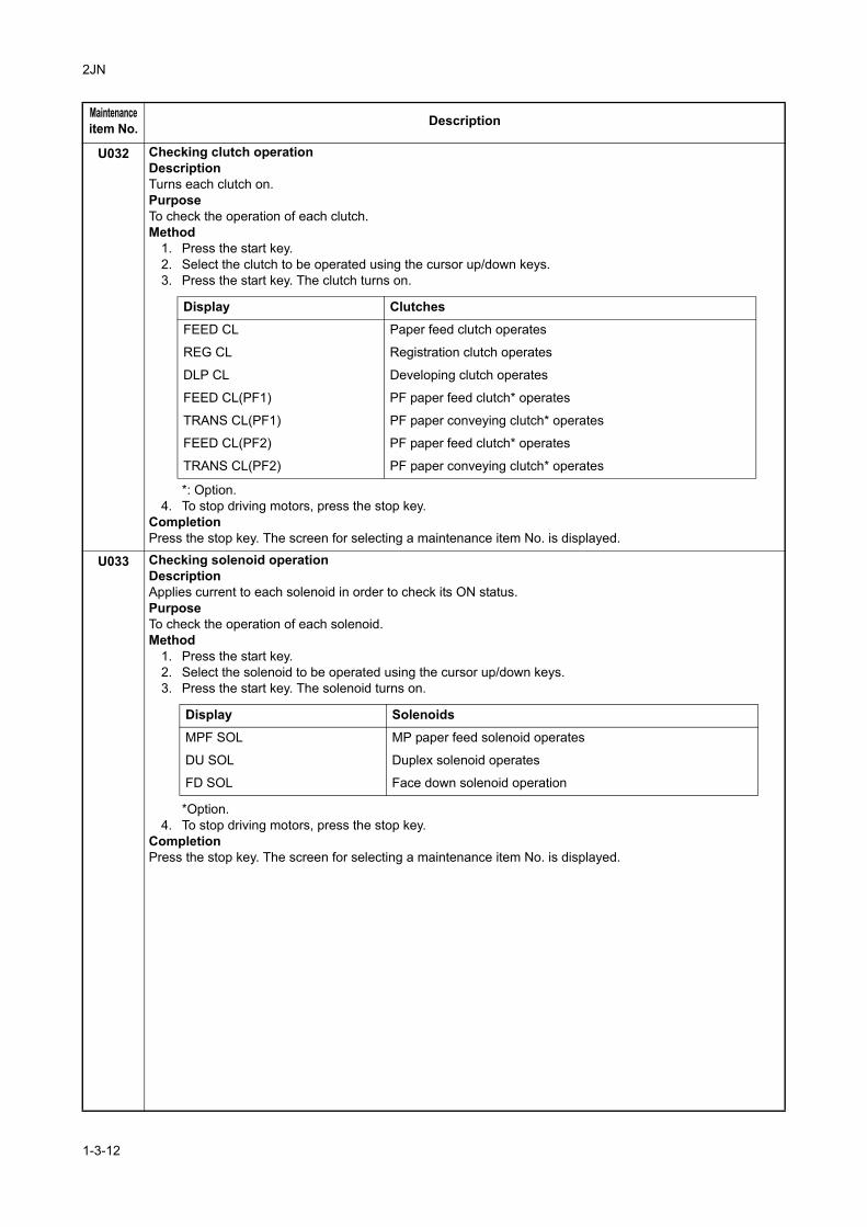
U032 Checking clutch operationDescriptionTurns each clutch on.PurposeTo check the operation of each clutch.Method
1. Press the start key.2. Select the clutch to be operated using the cursor up/down keys.3. Press the start key. The clutch turns on.
*: Option.4. To stop driving motors, press the stop key.
Completion Press the stop key. The screen for selecting a maintenance item No. is displayed.
U033 Checking solenoid operationDescriptionApplies current to each solenoid in order to check its ON status.PurposeTo check the operation of each solenoid.Method
1. Press the start key.2. Select the solenoid to be operated using the cursor up/down keys.3. Press the start key. The solenoid turns on.
*Option.4. To stop driving motors, press the stop key.
CompletionPress the stop key. The screen for selecting a maintenance item No. is displayed.
Maintenanceitem No. Description
Display Clutches
FEED CL Paper feed clutch operates
REG CL Registration clutch operates
DLP CL Developing clutch operates
FEED CL(PF1) PF paper feed clutch* operates
TRANS CL(PF1) PF paper conveying clutch* operates
FEED CL(PF2) PF paper feed clutch* operates
TRANS CL(PF2) PF paper conveying clutch* operates
Display Solenoids
MPF SOL MP paper feed solenoid operates
DU SOL Duplex solenoid operates
FD SOL Face down solenoid operation
1-3-12
2JN
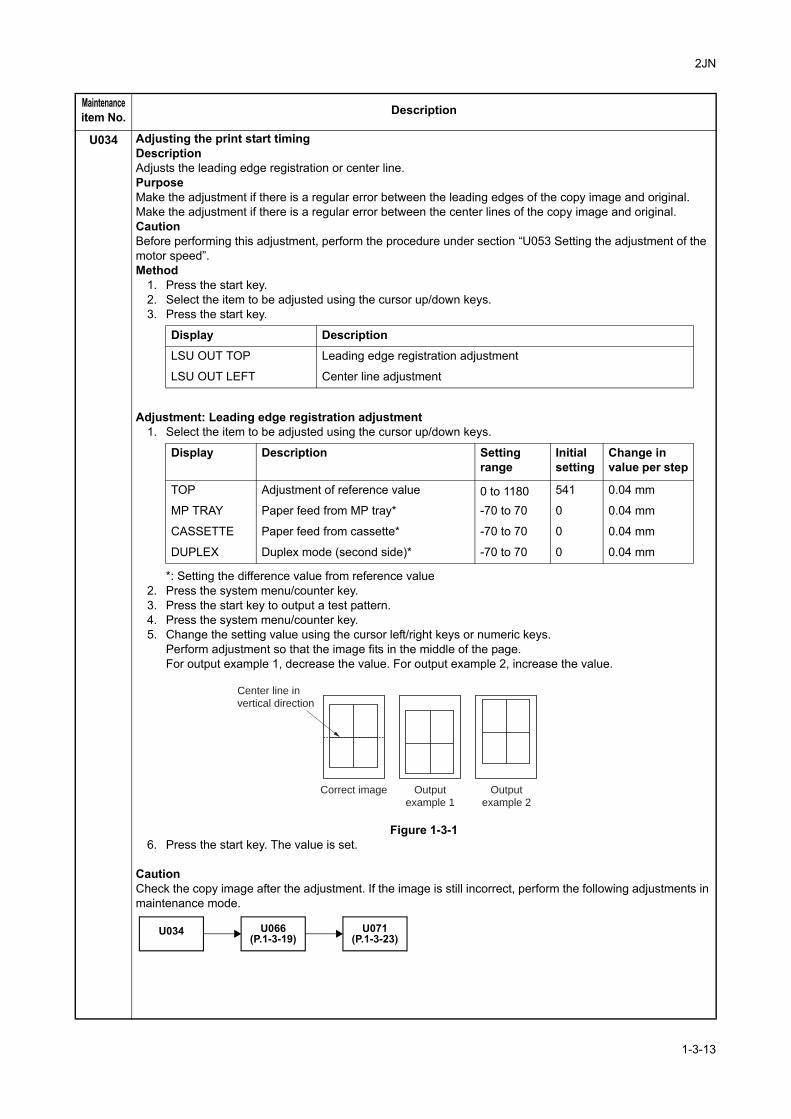
U034 Adjusting the print start timingDescriptionAdjusts the leading edge registration or center line.PurposeMake the adjustment if there is a regular error between the leading edges of the copy image and original.Make the adjustment if there is a regular error between the center lines of the copy image and original.CautionBefore performing this adjustment, perform the procedure under section “U053 Setting the adjustment of the motor speed”.Method
1. Press the start key.2. Select the item to be adjusted using the cursor up/down keys.3. Press the start key.
Adjustment: Leading edge registration adjustment1. Select the item to be adjusted using the cursor up/down keys.
*: Setting the difference value from reference value2. Press the system menu/counter key.3. Press the start key to output a test pattern.4. Press the system menu/counter key.5. Change the setting value using the cursor left/right keys or numeric keys.
Perform adjustment so that the image fits in the middle of the page.For output example 1, decrease the value. For output example 2, increase the value.
Figure 1-3-16. Press the start key. The value is set.
CautionCheck the copy image after the adjustment. If the image is still incorrect, perform the following adjustments in maintenance mode.
Maintenanceitem No. Description
Display Description
LSU OUT TOP Leading edge registration adjustment
LSU OUT LEFT Center line adjustment
Display Description Settingrange
Initialsetting
Change invalue per step
TOP Adjustment of reference value 0 to 1180 541 0.04 mm
MP TRAY Paper feed from MP tray* -70 to 70 0 0.04 mm
CASSETTE Paper feed from cassette* -70 to 70 0 0.04 mm
DUPLEX Duplex mode (second side)* -70 to 70 0 0.04 mm
Center line in
vertical direction
Correct image Output
example 1
Output
example 2
U034 U066(P.1-3-19)
U071(P.1-3-23)
1-3-13
2JN
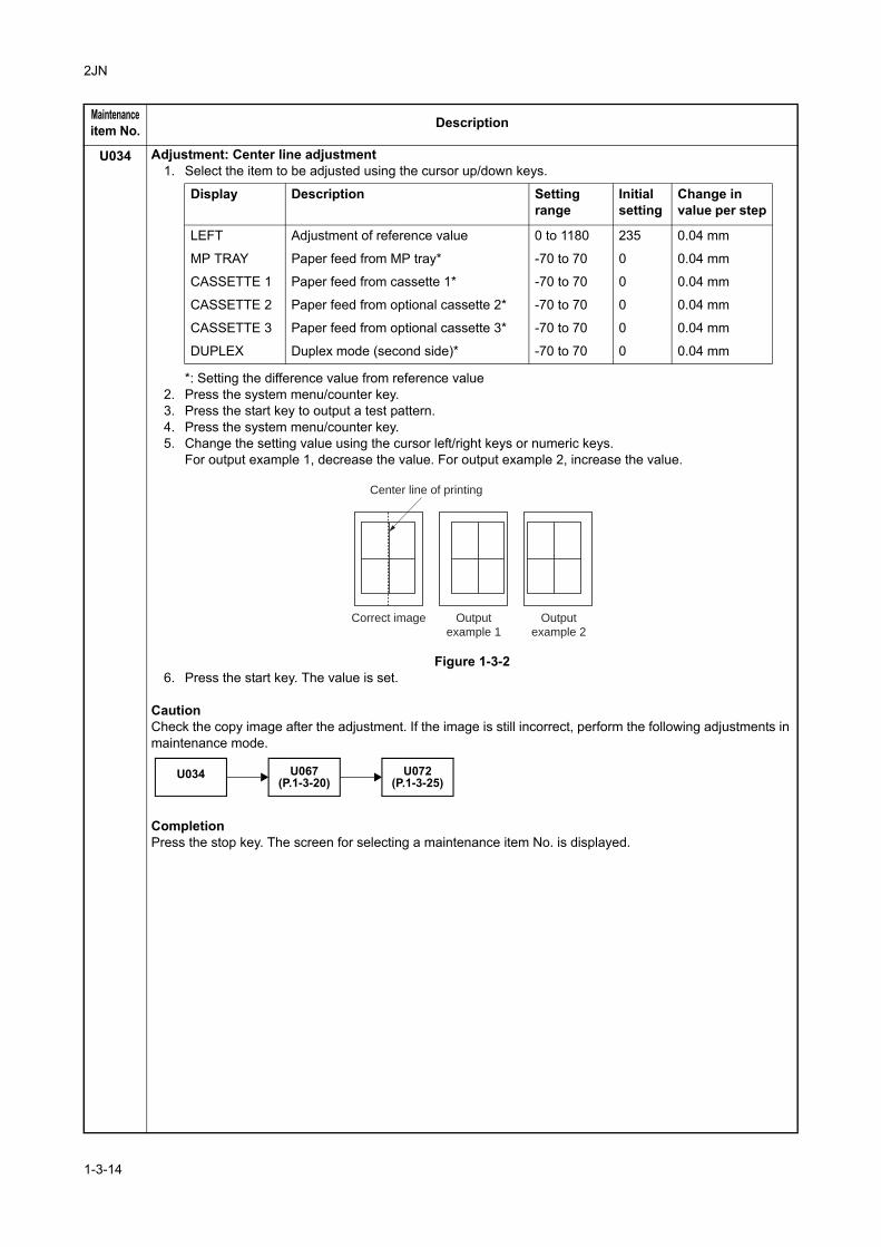
U034 Adjustment: Center line adjustment1. Select the item to be adjusted using the cursor up/down keys.
*: Setting the difference value from reference value2. Press the system menu/counter key.3. Press the start key to output a test pattern.4. Press the system menu/counter key.5. Change the setting value using the cursor left/right keys or numeric keys.
For output example 1, decrease the value. For output example 2, increase the value.
Figure 1-3-26. Press the start key. The value is set.
CautionCheck the copy image after the adjustment. If the image is still incorrect, perform the following adjustments in maintenance mode.
CompletionPress the stop key. The screen for selecting a maintenance item No. is displayed.
Maintenanceitem No. Description
Display Description Settingrange
Initialsetting
Change invalue per step
LEFT Adjustment of reference value 0 to 1180 235 0.04 mm
MP TRAY Paper feed from MP tray* -70 to 70 0 0.04 mm
CASSETTE 1 Paper feed from cassette 1* -70 to 70 0 0.04 mm
CASSETTE 2 Paper feed from optional cassette 2* -70 to 70 0 0.04 mm
CASSETTE 3 Paper feed from optional cassette 3* -70 to 70 0 0.04 mm
DUPLEX Duplex mode (second side)* -70 to 70 0 0.04 mm
Center line of printing
Correct image Output
example 1
Output
example 2
U034 U067(P.1-3-20)
U072(P.1-3-25)
1-3-14
2JN
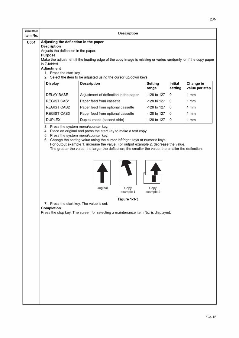
U051 Adjusting the deflection in the paperDescriptionAdjusts the deflection in the paper.PurposeMake the adjustment if the leading edge of the copy image is missing or varies randomly, or if the copy paper is Z-folded.Adjustment
1. Press the start key.2. Select the item to be adjusted using the cursor up/down keys.
3. Press the system menu/counter key.4. Place an original and press the start key to make a test copy.5. Press the system menu/counter key.6. Change the setting value using the cursor left/right keys or numeric keys.
For output example 1, increase the value. For output example 2, decrease the value.The greater the value, the larger the deflection; the smaller the value, the smaller the deflection.
Figure 1-3-37. Press the start key. The value is set.
CompletionPress the stop key. The screen for selecting a maintenance item No. is displayed.
Maintenanceitem No. Description
Display Description Settingrange
Initialsetting
Change invalue per step
DELAY BASE Adjustment of deflection in the paper -128 to 127 0 1 mm
REGIST CAS1 Paper feed from cassette -128 to 127 0 1 mm
REGIST CAS2 Paper feed from optional cassette -128 to 127 0 1 mm
REGIST CAS3 Paper feed from optional cassette -128 to 127 0 1 mm
DUPLEX Duplex mode (second side) -128 to 127 0 1 mm
Original Copy
example 1
Copy
example 2
1-3-15
2JN
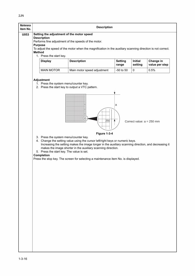
U053 Setting the adjustment of the motor speedDescriptionPerforms fine adjustment of the speeds of the motor.PurposeTo adjust the speed of the motor when the magnification in the auxiliary scanning direction is not correct.Method
1. Press the start key.
Adjustment1. Press the system menu/counter key.2. Press the start key to output a VTC pattern.
Figure 1-3-43. Press the system menu/counter key.4. Change the setting value using the cursor left/right keys or numeric keys.
Increasing the setting makes the image longer in the auxiliary scanning direction, and decreasing it makes the image shorter in the auxiliary scanning direction.
5. Press the start key. The value is set.CompletionPress the stop key. The screen for selecting a maintenance item No. is displayed.
Maintenanceitem No. Description
Display Description Settingrange
Initialsetting
Change invalue per step
MAIN MOTOR Main motor speed adjustment -50 to 50 0 0.5%
100
150
200
250
250 Correct value: a = 250 mm
a
1-3-16
2JN
U063 Adjusting the shading positionDescriptionChanges the shading position of the scanner.PurposeUsed when white lines continue to appear longitudinally on the image after the shading plate is cleaned. This is due to flaws or stains inside the shading plate. To prevent this problem, the shading position should be changed so that shading is possible without being affected by the flaws or stains.Method
1. Press the start key.2. Change the setting using the cursor left/right keys or numeric keys.
Increasing the setting moves the shading position toward the machine left, and decreasing it moves the position toward the machine right.
3. Press the start key. The value is set.SupplementWhile this maintenance item is being executed, copying from an original is available in interrupt copying mode (which is activated by pressing the system menu/counter key).CompletionPress the stop key. The screen for selecting a maintenance item No. is displayed.
Maintenanceitem No. Description
Description Setting range Initial setting Change in value per step
Shading position -32 to 20 0 0.086 mm
1-3-17
2JN
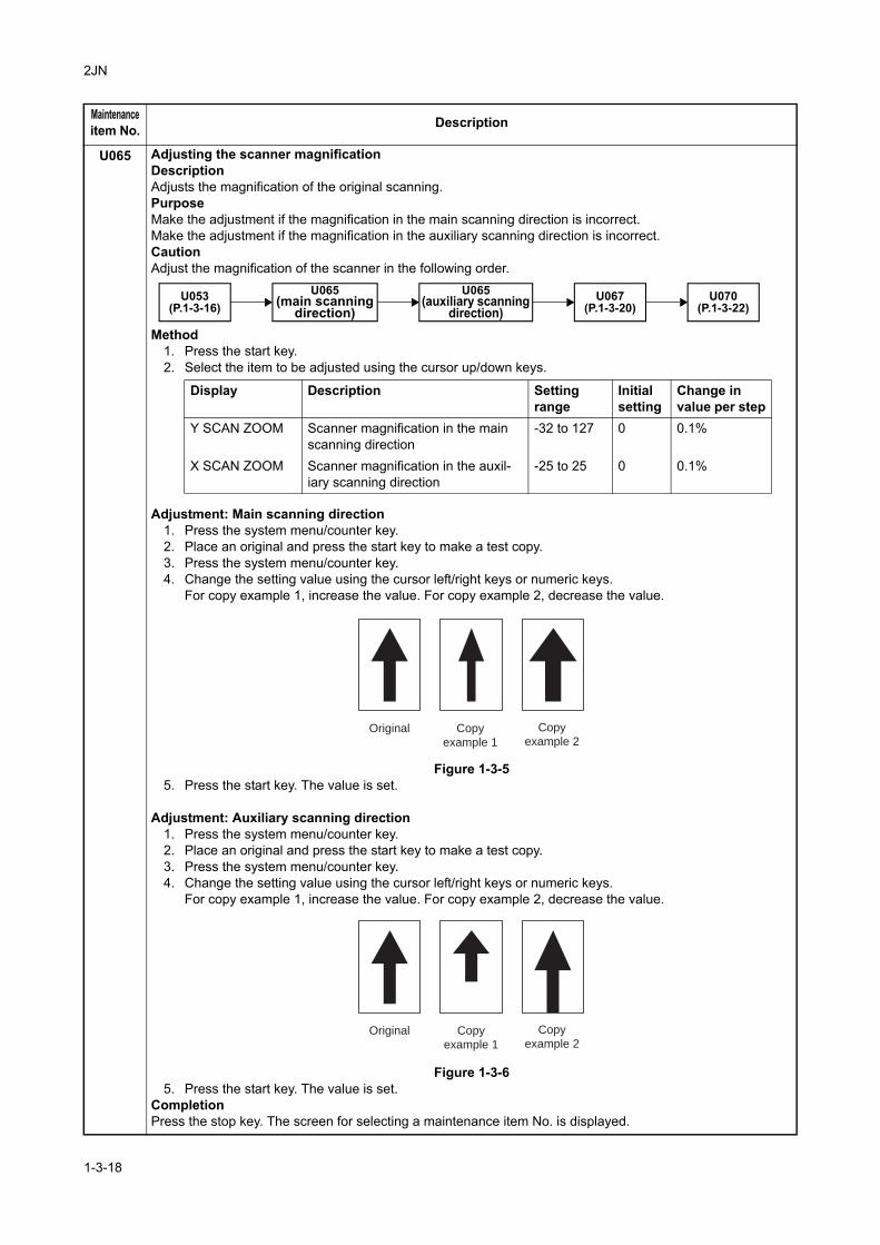
U065 Adjusting the scanner magnificationDescriptionAdjusts the magnification of the original scanning.PurposeMake the adjustment if the magnification in the main scanning direction is incorrect.Make the adjustment if the magnification in the auxiliary scanning direction is incorrect.CautionAdjust the magnification of the scanner in the following order.
Method1. Press the start key.2. Select the item to be adjusted using the cursor up/down keys.
Adjustment: Main scanning direction1. Press the system menu/counter key.2. Place an original and press the start key to make a test copy.3. Press the system menu/counter key.4. Change the setting value using the cursor left/right keys or numeric keys.
For copy example 1, increase the value. For copy example 2, decrease the value.
Figure 1-3-55. Press the start key. The value is set.
Adjustment: Auxiliary scanning direction1. Press the system menu/counter key.2. Place an original and press the start key to make a test copy.3. Press the system menu/counter key.4. Change the setting value using the cursor left/right keys or numeric keys.
For copy example 1, increase the value. For copy example 2, decrease the value.
Figure 1-3-65. Press the start key. The value is set.
CompletionPress the stop key. The screen for selecting a maintenance item No. is displayed.
Maintenanceitem No. Description
U065(main scanning
direction)U053
(P.1-3-16)U067
(P.1-3-20)U065
(auxiliary scanning direction)
U070(P.1-3-22)
Display Description Settingrange
Initialsetting
Change invalue per step
Y SCAN ZOOM Scanner magnification in the main scanning direction
-32 to 127 0 0.1%
X SCAN ZOOM Scanner magnification in the auxil-iary scanning direction
-25 to 25 0 0.1%
Original Copy
example 1
Copy
example 2
Original Copy
example 1
Copy
example 2
1-3-18
2JN
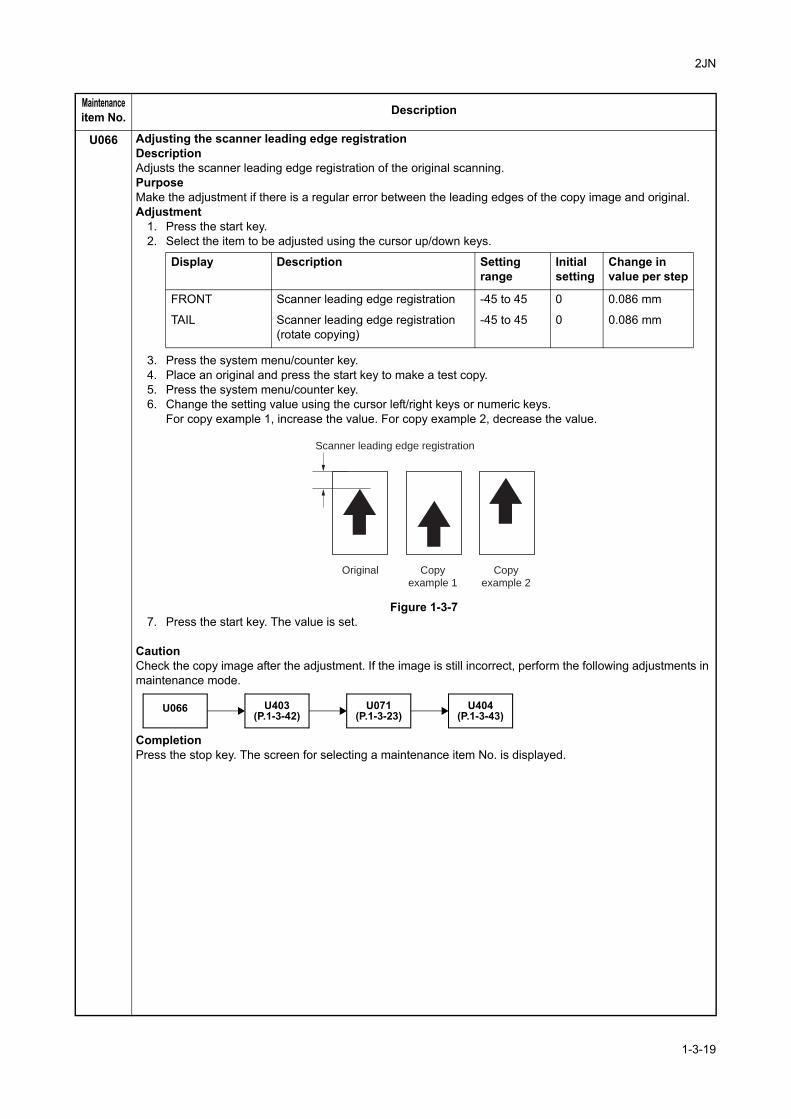
U066 Adjusting the scanner leading edge registrationDescriptionAdjusts the scanner leading edge registration of the original scanning.PurposeMake the adjustment if there is a regular error between the leading edges of the copy image and original.Adjustment
1. Press the start key.2. Select the item to be adjusted using the cursor up/down keys.
3. Press the system menu/counter key.4. Place an original and press the start key to make a test copy.5. Press the system menu/counter key.6. Change the setting value using the cursor left/right keys or numeric keys.
For copy example 1, increase the value. For copy example 2, decrease the value.
Figure 1-3-77. Press the start key. The value is set.
CautionCheck the copy image after the adjustment. If the image is still incorrect, perform the following adjustments in maintenance mode.
CompletionPress the stop key. The screen for selecting a maintenance item No. is displayed.
Maintenanceitem No. Description
Display Description Settingrange
Initialsetting
Change invalue per step
FRONT Scanner leading edge registration -45 to 45 0 0.086 mm
TAIL Scanner leading edge registration (rotate copying)
-45 to 45 0 0.086 mm
Original
Scanner leading edge registration
Copy
example 1
Copy
example 2
U066 U403(P.1-3-42)
U071(P.1-3-23)
U404(P.1-3-43)
1-3-19
2JN
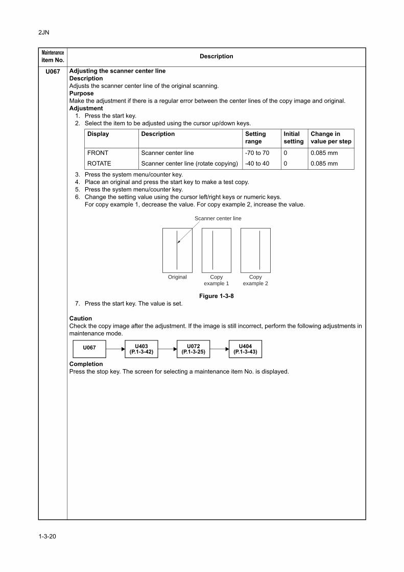
U067 Adjusting the scanner center lineDescriptionAdjusts the scanner center line of the original scanning.PurposeMake the adjustment if there is a regular error between the center lines of the copy image and original.Adjustment
1. Press the start key.2. Select the item to be adjusted using the cursor up/down keys.
3. Press the system menu/counter key.4. Place an original and press the start key to make a test copy.5. Press the system menu/counter key.6. Change the setting value using the cursor left/right keys or numeric keys.
For copy example 1, decrease the value. For copy example 2, increase the value.
Figure 1-3-87. Press the start key. The value is set.
CautionCheck the copy image after the adjustment. If the image is still incorrect, perform the following adjustments in maintenance mode.
CompletionPress the stop key. The screen for selecting a maintenance item No. is displayed.
Maintenanceitem No. Description
Display Description Settingrange
Initialsetting
Change invalue per step
FRONT Scanner center line -70 to 70 0 0.085 mm
ROTATE Scanner center line (rotate copying) -40 to 40 0 0.085 mm
Original Copy
example 1
Copy
example 2
Scanner center line
U067 U403(P.1-3-42)
U072(P.1-3-25)
U404(P.1-3-43)
1-3-20
2JN
U068 Adjusting the scanning position for originals from the DPDescriptionAdjusts the position for scanning originals from the DP. Performs the test copy at the four scanning positions after adjusting.PurposeUsed when the image fogging occurs because the scanning position is not proper when the DP is used. Run U071 to adjust the timing of DP leading edge when the scanning position is changed.Setting
1. Press the start key.
2. Select [DP READ].3. Change the setting using the cursor left/right keys or numeric keys.
When the setting value is increased, the scanning position moves to the right and it moves to the left when the setting value is decreased.
4. Press the start key. The value is set.5. Select [BLACK LINE] using the cursor up/down keys.6. Select the scanning position using the cursor left/right keys or numeric keys.7. Press the start key. The value is set.8. Set the original (the one which density is known) in the DP and press the system menu/counter key. The
screen for the test copy mode is displayed.9. Press the start key. Test copy is executed.10. Perform the test copy at each scanning position with the setting value from 0 to 3 and check that no
black line appears and the image is normally scanned.CompletionPress the stop key. The screen for selecting a maintenance item No. is displayed.
Maintenanceitem No. Description
Display Description Settingrange
Initialsetting
Change invalue per step
DP READ Starting position adjustment for scanning originals
-33 to 33 0 0.086 mm
BLACK LINE Scanning position for the test copy originals
0 to 3 0 0.22 mm
1-3-21
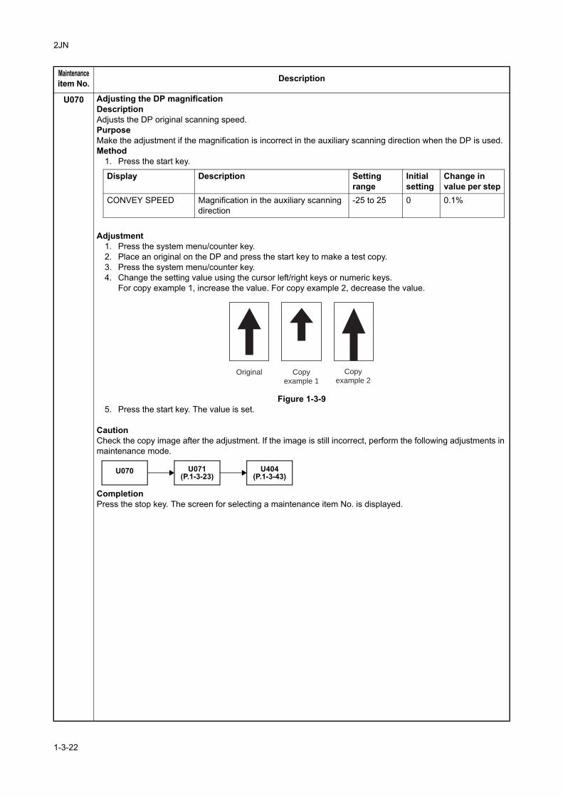
2JN
U070 Adjusting the DP magnificationDescriptionAdjusts the DP original scanning speed.PurposeMake the adjustment if the magnification is incorrect in the auxiliary scanning direction when the DP is used.Method
1. Press the start key.
Adjustment1. Press the system menu/counter key.2. Place an original on the DP and press the start key to make a test copy.3. Press the system menu/counter key.4. Change the setting value using the cursor left/right keys or numeric keys.
For copy example 1, increase the value. For copy example 2, decrease the value.
Figure 1-3-95. Press the start key. The value is set.
CautionCheck the copy image after the adjustment. If the image is still incorrect, perform the following adjustments in maintenance mode.
CompletionPress the stop key. The screen for selecting a maintenance item No. is displayed.
Maintenanceitem No. Description
Display Description Settingrange
Initialsetting
Change invalue per step
CONVEY SPEED Magnification in the auxiliary scanning direction
-25 to 25 0 0.1%
Original Copy
example 1
Copy
example 2
U070 U071(P.1-3-23)
U404(P.1-3-43)
1-3-22
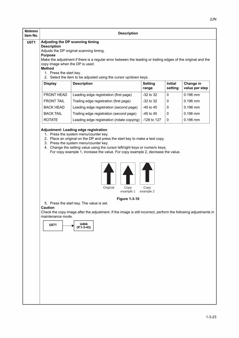
2JN
U071 Adjusting the DP scanning timingDescriptionAdjusts the DP original scanning timing.PurposeMake the adjustment if there is a regular error between the leading or trailing edges of the original and the copy image when the DP is used.Method
1. Press the start key.2. Select the item to be adjusted using the cursor up/down keys.
Adjustment: Leading edge registration1. Press the system menu/counter key.2. Place an original on the DP and press the start key to make a test copy.3. Press the system menu/counter key.4. Change the setting value using the cursor left/right keys or numeric keys.
For copy example 1, increase the value. For copy example 2, decrease the value.
Figure 1-3-105. Press the start key. The value is set.
CautionCheck the copy image after the adjustment. If the image is still incorrect, perform the following adjustments in maintenance mode.
Maintenanceitem No. Description
Display Description Settingrange
Initialsetting
Change invalue per step
FRONT HEAD Leading edge registration (first page) -32 to 32 0 0.196 mm
FRONT TAIL Trailing edge registration (first page) -32 to 32 0 0.196 mm
BACK HEAD Leading edge registration (second page) -45 to 45 0 0.196 mm
BACK TAIL Trailing edge registration (second page) -45 to 45 0 0.196 mm
ROTATE Leading edge registration (rotate copying) -128 to 127 0 0.196 mm
Original Copy
example 1
Copy
example 2
U071 U404(P.1-3-43)
1-3-23
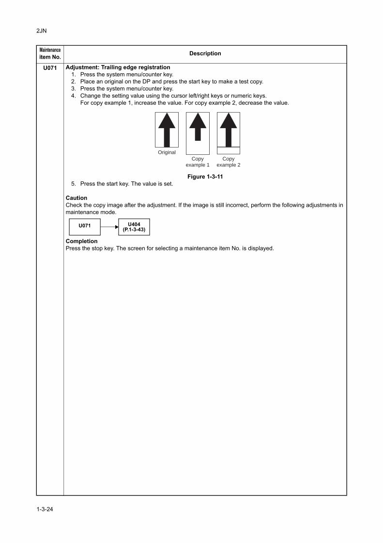
2JN
U071 Adjustment: Trailing edge registration1. Press the system menu/counter key.2. Place an original on the DP and press the start key to make a test copy.3. Press the system menu/counter key.4. Change the setting value using the cursor left/right keys or numeric keys.
For copy example 1, increase the value. For copy example 2, decrease the value.
Figure 1-3-115. Press the start key. The value is set.
CautionCheck the copy image after the adjustment. If the image is still incorrect, perform the following adjustments in maintenance mode.
CompletionPress the stop key. The screen for selecting a maintenance item No. is displayed.
Maintenanceitem No. Description
Original
Copy
example 1
Copy
example 2
U071 U404(P.1-3-43)
1-3-24
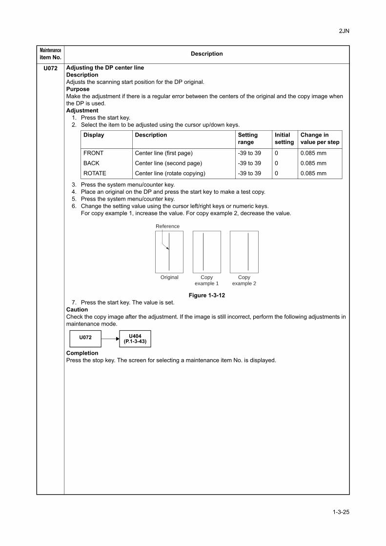
2JN
U072 Adjusting the DP center lineDescriptionAdjusts the scanning start position for the DP original.PurposeMake the adjustment if there is a regular error between the centers of the original and the copy image when the DP is used.Adjustment
1. Press the start key.2. Select the item to be adjusted using the cursor up/down keys.
3. Press the system menu/counter key.4. Place an original on the DP and press the start key to make a test copy.5. Press the system menu/counter key.6. Change the setting value using the cursor left/right keys or numeric keys.
For copy example 1, increase the value. For copy example 2, decrease the value.
Figure 1-3-127. Press the start key. The value is set.
CautionCheck the copy image after the adjustment. If the image is still incorrect, perform the following adjustments in maintenance mode.
CompletionPress the stop key. The screen for selecting a maintenance item No. is displayed.
Maintenanceitem No. Description
Display Description Settingrange
Initialsetting
Change invalue per step
FRONT Center line (first page) -39 to 39 0 0.085 mm
BACK Center line (second page) -39 to 39 0 0.085 mm
ROTATE Center line (rotate copying) -39 to 39 0 0.085 mm
Original Copy
example 1
Copy
example 2
Reference
U072 U404(P.1-3-43)
1-3-25
2JN
U073 Checking scanner operationDescriptionSimulates the scanner operation under arbitrary conditions.PurposeTo check scanner operation.Start
1. Press the start key.2. Select the item to be operated using the cursor up/down keys.
Setting: SCANNER MOTOR1. Select [SCANNER MOTOR].2. Select the item to be set using the cursor up/down keys.3. Change the setting using the cursor left/right keys.
Original sizes for each setting in SIZE
4. Select [EXECUTE] using the cursor up/down keys.5. Press the start key. Scanning starts under the selected conditions.6. To stop operation, press the stop key.
Method: HOME POSITION1. Select [HOME POSITION].2. Press the start key.
The mirror frame of the scanner moves to the home position.Method: DUST CHECK
1. Select [DUST CHECK].2. Press the start key. The exposure lamp lights.3. To turn the exposure lamp off, press the stop key.
Method: DP READING1. Select [DP READING].2. Press the start key.
The mirror frame of the scanner moves to the reading position.CompletionPress the stop key when scanning stops. The screen for selecting a maintenance item No. is displayed.
Maintenanceitem No. Description
Display Description
SCANNER MOTOR Scanner operation
HOME POSITION Home position operation
DUST CHECK Dust adhesion check operation with lamp on
DP READING DP scanning position operation
Display Operating conditions Setting rangeZOOM Magnification 25 to 400%
SIZE Original size See below.
LAMP On and off of the exposure lamp 0 (off) or 1 (on)
Setting Paper size Setting Paper size
5000 A4 7800 Folio
6100 B5R 8400 8 1/2" x 14"
5000 A5R 6600 8 1/2" x 11"
1-3-26
2JN
U087 Setting DP reading position modification operationDescriptionThe presence or absence of dust is determined by comparing the scan data of the original trailing edge and that taken after the original is conveyed past the DP original scanning position. If dust is identified, the DP original scanning position is adjusted for the following originals.PurposeWhen using DP, to solve the problem when black lines occurs due to the dust with respect to original reading position.Method
1. Press the start key. 2. Select the item to be set using the cursor up/down keys.
Setting: Standard data when dust is detected1. Select the item to be set using the cursor up/down keys.2. Change the value using the cursor left/right keys or numeric keys.
3. Press the start key. The value is set.
Setting: Initialization of original reading position1. Select [CLEAR] using the cursor up/down keys.2. Press the start key. The setting is cleared.
CompletionPress the stop key. The screen for selecting a maintenance item No. is displayed.
Maintenanceitem No. Description
Display Description
CCD Setting of standard data when dust is detected.
BLACK LINE Initialization of original reading position.
Display Description Setting range Initial setting
CCD R Lowest density of the R regard as the dust 0 to 255 125
CCD G Lowest density of the G regard as the dust 0 to 255 125
CCD B Lowest density of the B regard as the dust 0 to 255 120
1-3-27
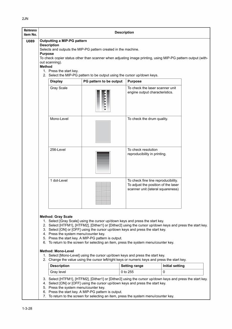
2JN
U089 Outputting a MIP-PG patternDescriptionSelects and outputs the MIP-PG pattern created in the machine.PurposeTo check copier status other than scanner when adjusting image printing, using MIP-PG pattern output (with-out scanning).Method
1. Press the start key.2. Select the MIP-PG pattern to be output using the cursor up/down keys.
Method: Gray Scale1. Select [Gray Scale] using the cursor up/down keys and press the start key.2. Select [HTFM1], [HTFM2], [Dither1] or [Dither2] using the cursor up/down keys and press the start key.3. Select [ON] or [OFF] using the cursor up/down keys and press the start key.4. Press the system menu/counter key.5. Press the start key. A MIP-PG pattern is output.6. To return to the screen for selecting an item, press the system menu/counter key.
Method: Mono-Level1. Select [Mono-Level] using the cursor up/down keys and press the start key.2. Change the value using the cursor left/right keys or numeric keys and press the start key.
3. Select [HTFM1], [HTFM2], [Dither1] or [Dither2] using the cursor up/down keys and press the start key.4. Select [ON] or [OFF] using the cursor up/down keys and press the start key.5. Press the system menu/counter key.6. Press the start key. A MIP-PG pattern is output.7. To return to the screen for selecting an item, press the system menu/counter key.
Maintenanceitem No. Description
Display PG pattern to be output Purpose
Gray Scale To check the laser scanner unit engine output characteristics.
Mono-Level To check the drum quality.
256-Level To check resolutionreproducibility in printing.
1 dot-Level To check fine line reproducibility.To adjust the position of the laser scanner unit (lateral squareness)
Description Setting range Initial settingGray level 0 to 255 0
1-3-28
2JN
U089 Method: 256-Level1. Select [256-Level] using the cursor up/down keys and press the start key.2. Select [HTFM1], [HTFM2], [Dither1] or [Dither2] using the cursor up/down keys and press the start key.3. Select [ON] or [OFF] using the cursor up/down keys and press the start key.4. Press the system menu/counter key.5. Press the start key. A MIP-PG pattern is output.6. To return to the screen for selecting an item, press the system menu/counter key.
Method: 1 dot-Level1. Select [1 dot-Level] using the cursor up/down keys and press the start key.2. Change the value using the cursor left/right keys or numeric keys and press the start key.
3. Press the system menu/counter key.4. Press the start key. A MIP-PG pattern is output.5. To return to the screen for selecting an item, press the system menu/counter key.
CompletionPress the stop key. The screen for selecting a maintenance item No. is displayed.
Maintenanceitem No. Description
Description Setting range Initial setting
Dot pattern 0 to 15 0
1-3-29
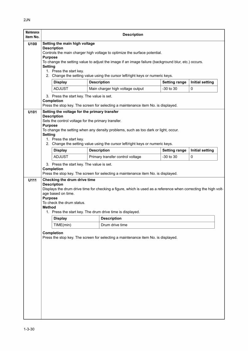
2JN
U100 Setting the main high voltageDescriptionControls the main charger high voltage to optimize the surface potential.PurposeTo change the setting value to adjust the image if an image failure (background blur, etc.) occurs.Setting
1. Press the start key.2. Change the setting value using the cursor left/right keys or numeric keys.
3. Press the start key. The value is set.CompletionPress the stop key. The screen for selecting a maintenance item No. is displayed.
U101 Setting the voltage for the primary transferDescriptionSets the control voltage for the primary transfer.PurposeTo change the setting when any density problems, such as too dark or light, occur.Setting
1. Press the start key.2. Change the setting value using the cursor left/right keys or numeric keys.
3. Press the start key. The value is set.CompletionPress the stop key. The screen for selecting a maintenance item No. is displayed.
U111 Checking the drum drive timeDescriptionDisplays the drum drive time for checking a figure, which is used as a reference when correcting the high volt-age based on time.PurposeTo check the drum status.Method
1. Press the start key. The drum drive time is displayed.
CompletionPress the stop key. The screen for selecting a maintenance item No. is displayed.
Maintenanceitem No. Description
Display Description Setting range Initial setting
ADJUST Main charger high voltage output -30 to 30 0
Display Description Setting range Initial settingADJUST Primary transfer control voltage -30 to 30 0
Display Description
TIME(min) Drum drive time
1-3-30
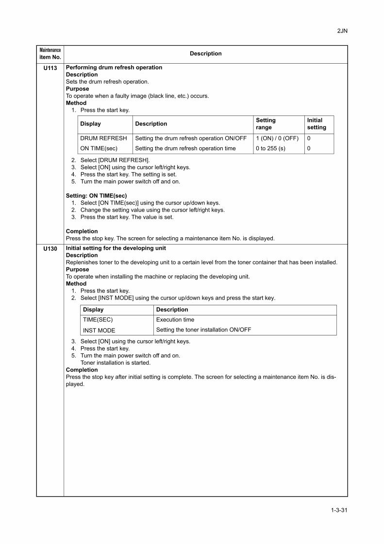
2JN
U113 Performing drum refresh operationDescriptionSets the drum refresh operation.PurposeTo operate when a faulty image (black line, etc.) occurs.Method
1. Press the start key.
2. Select [DRUM REFRESH].3. Select [ON] using the cursor left/right keys.4. Press the start key. The setting is set.5. Turn the main power switch off and on.
Setting: ON TIME(sec)1. Select [ON TIME(sec)] using the cursor up/down keys.2. Change the setting value using the cursor left/right keys.3. Press the start key. The value is set.
CompletionPress the stop key. The screen for selecting a maintenance item No. is displayed.
U130 Initial setting for the developing unitDescriptionReplenishes toner to the developing unit to a certain level from the toner container that has been installed.PurposeTo operate when installing the machine or replacing the developing unit.Method
1. Press the start key.2. Select [INST MODE] using the cursor up/down keys and press the start key.
3. Select [ON] using the cursor left/right keys.4. Press the start key.5. Turn the main power switch off and on.
Toner installation is started.CompletionPress the stop key after initial setting is complete. The screen for selecting a maintenance item No. is dis-played.
Maintenanceitem No. Description
Display Description Settingrange
Initialsetting
DRUM REFRESH Setting the drum refresh operation ON/OFF 1 (ON) / 0 (OFF) 0
ON TIME(sec) Setting the drum refresh operation time 0 to 255 (s) 0
Display Description
TIME(SEC) Execution time
INST MODE Setting the toner installation ON/OFF
1-3-31
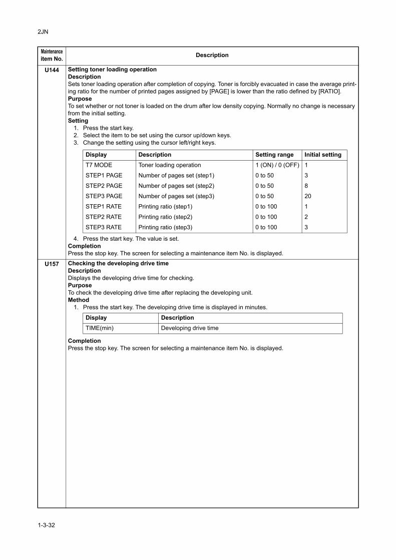
2JN
U144 Setting toner loading operationDescriptionSets toner loading operation after completion of copying. Toner is forcibly evacuated in case the average print-ing ratio for the number of printed pages assigned by [PAGE] is lower than the ratio defined by [RATIO].PurposeTo set whether or not toner is loaded on the drum after low density copying. Normally no change is necessary from the initial setting.Setting
1. Press the start key.2. Select the item to be set using the cursor up/down keys.3. Change the setting using the cursor left/right keys.
4. Press the start key. The value is set.CompletionPress the stop key. The screen for selecting a maintenance item No. is displayed.
U157 Checking the developing drive timeDescriptionDisplays the developing drive time for checking.PurposeTo check the developing drive time after replacing the developing unit.Method
1. Press the start key. The developing drive time is displayed in minutes.
CompletionPress the stop key. The screen for selecting a maintenance item No. is displayed.
Maintenanceitem No. Description
Display Description Setting range Initial setting
T7 MODE Toner loading operation 1 (ON) / 0 (OFF) 1
STEP1 PAGE Number of pages set (step1) 0 to 50 3
STEP2 PAGE Number of pages set (step2) 0 to 50 8
STEP3 PAGE Number of pages set (step3) 0 to 50 20
STEP1 RATE Printing ratio (step1) 0 to 100 1
STEP2 RATE Printing ratio (step2) 0 to 100 2
STEP3 RATE Printing ratio (step3) 0 to 100 3
Display DescriptionTIME(min) Developing drive time
1-3-32
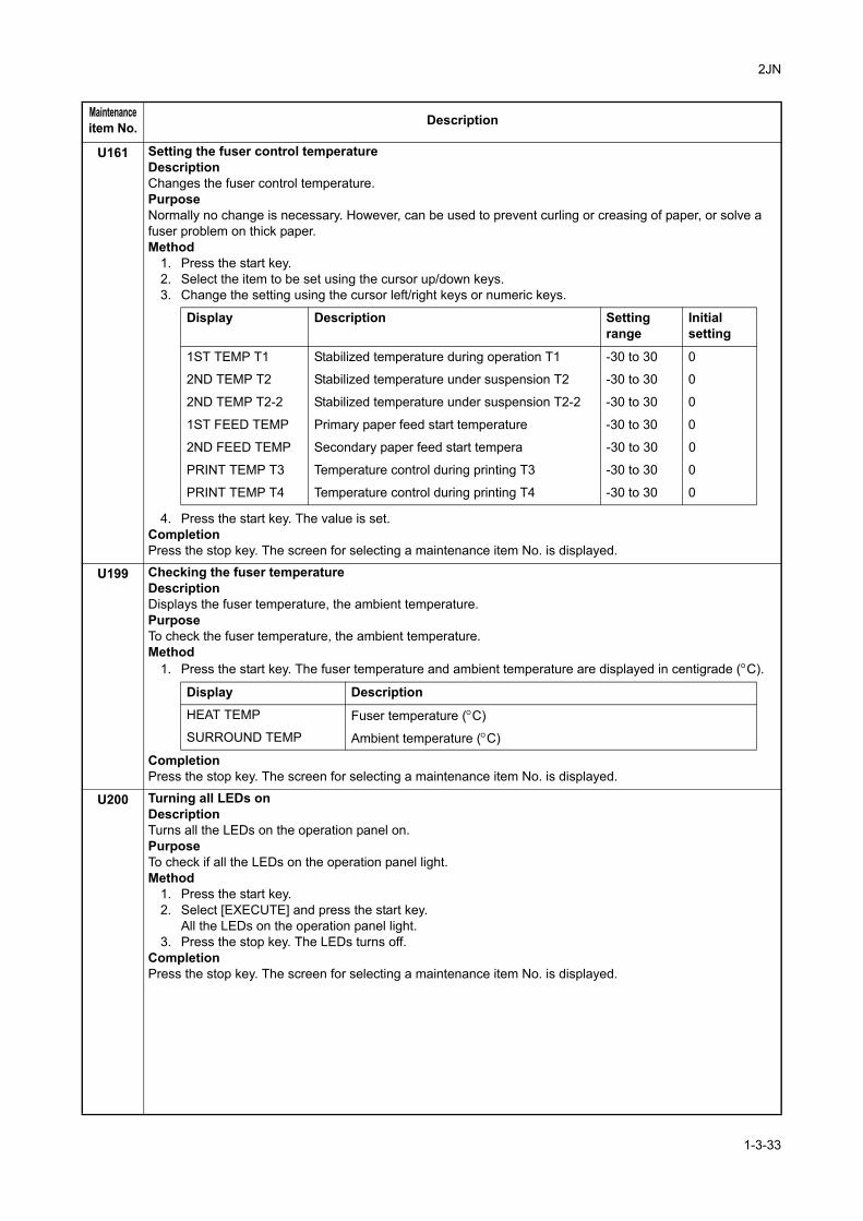
2JN
U161 Setting the fuser control temperatureDescriptionChanges the fuser control temperature.PurposeNormally no change is necessary. However, can be used to prevent curling or creasing of paper, or solve a fuser problem on thick paper.Method
1. Press the start key.2. Select the item to be set using the cursor up/down keys.3. Change the setting using the cursor left/right keys or numeric keys.
4. Press the start key. The value is set.CompletionPress the stop key. The screen for selecting a maintenance item No. is displayed.
U199 Checking the fuser temperatureDescriptionDisplays the fuser temperature, the ambient temperature. PurposeTo check the fuser temperature, the ambient temperature. Method
1. Press the start key. The fuser temperature and ambient temperature are displayed in centigrade (°C).
Completion Press the stop key. The screen for selecting a maintenance item No. is displayed.
U200 Turning all LEDs onDescriptionTurns all the LEDs on the operation panel on.PurposeTo check if all the LEDs on the operation panel light.Method
1. Press the start key. 2. Select [EXECUTE] and press the start key.
All the LEDs on the operation panel light.3. Press the stop key. The LEDs turns off.
Completion Press the stop key. The screen for selecting a maintenance item No. is displayed.
Maintenanceitem No. Description
Display Description Setting range
Initial setting
1ST TEMP T1 Stabilized temperature during operation T1 -30 to 30 0
2ND TEMP T2 Stabilized temperature under suspension T2 -30 to 30 0
2ND TEMP T2-2 Stabilized temperature under suspension T2-2 -30 to 30 0
1ST FEED TEMP Primary paper feed start temperature -30 to 30 0
2ND FEED TEMP Secondary paper feed start tempera -30 to 30 0
PRINT TEMP T3 Temperature control during printing T3 -30 to 30 0
PRINT TEMP T4 Temperature control during printing T4 -30 to 30 0
Display DescriptionHEAT TEMP Fuser temperature (°C) SURROUND TEMP Ambient temperature (°C)
1-3-33
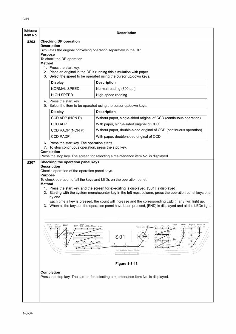
2JN
U203 Checking DP operationDescriptionSimulates the original conveying operation separately in the DP.PurposeTo check the DP operation.Method
1. Press the start key.2. Place an original in the DP if running this simulation with paper.3. Select the speed to be operated using the cursor up/down keys.
4. Press the start key.5. Select the item to be operated using the cursor up/down keys.
6. Press the start key. The operation starts. 7. To stop continuous operation, press the stop key.
CompletionPress the stop key. The screen for selecting a maintenance item No. is displayed.
U207 Checking the operation panel keysDescriptionChecks operation of the operation panel keys.PurposeTo check operation of all the keys and LEDs on the operation panel.Method
1. Press the start key. and the screen for executing is displayed. [S01] is displayed2. Starting with the system menu/counter key in the left most column, press the operation panel keys one
by one. Each time a key is pressed, the count will increase and the corresponding LED (if any) will light up.
3. When all the keys on the operation panel have been pressed, [END] is displayed and all the LEDs light.
Figure 1-3-13
CompletionPress the stop key. The screen for selecting a maintenance item No. is displayed.
Maintenanceitem No. Description
Display Description
NORMAL SPEED Normal reading (600 dpi)
HIGH SPEED High-speed reading
Display Description
CCD ADP (NON P) Without paper, single-sided original of CCD (continuous operation)
CCD ADP With paper, single-sided original of CCD
CCD RADP (NON P) Without paper, double-sided original of CCD (continuous operation)
CCD RADP With paper, double-sided original of CCD
1-3-34
2JN
U223 Operation panel lockDescriptionSets the operation panel lock function to ON or OFF.PurposeTo restrict operation in the system menu on the operation panel.Setting
1. Press the start key. 2. Select the item using the cursor up/down keys.
Initial setting: UNLOCK3. Press the start key. The setting is set.
CompletionPress the stop key. The screen for selecting a maintenance item No. is displayed.
U243 Checking the operation of the DP motor solenoids and clutchDescriptionTurns the motor, solenoids and clutch in the DP on.PurposeTo check the operation of the DP motor, solenoids and clutch.Method
1. Press the start key.2. Select the item to be operated using the cursor up/down keys.3. Press the start key. The operation starts.
4. To stop operation, press the stop key.Completion Press the stop key when operation stops. The screen for selecting a maintenance item No. is displayed.
Maintenanceitem No. Description
Display Description
UNLOCK Release the lock of the operation from the system menu
PARTIAL LOCK Partially lock the operation from the system menu
LOCK Entirely lock the operation from the system menu
Display Motor, solenoids and clutch
DP FEED MOT DP paper feed motor is turned on.
DP REV PRS SOL DP switchback pressure solenoid is turned on.
DP REV BRCH SOL DP switchback feedshift solenoid is turned on.
DP FEED CL DP paper feed clutch is turned on.
1-3-35
2JN
U244 Checking the DP sensorsDescriptionDisplays the status of the respective sensors in the DP.PurposeTo check if respective sensors in the DP operate correctly.Method
1. Press the start key.2. Turn the respective sensors on and off manually to check the status.
When a sensor is detected to be in the ON position, the display for that sensor will be highlighted.
CompletionPress the stop key. The screen for selecting a maintenance item No. is displayed.
U250 Setting the maintenance cycleDescriptionDisplays and changes the maintenance cycle.PurposeTo check and change the maintenance cycle.Method
1. Press the start key. The currently set maintenance cycle is displayed.Setting
1. Select [M.CNT A] using the cursor up/down keys.2. Change the setting using the cursor left/right keys or numeric keys.
3. Press the start key. The value is set.Clearing
1. Select [CLEAR] using the cursor up/down keys.2. Press the start key. The count is cleared.
CompletionPress the stop key. The screen for selecting a maintenance item No. is displayed.
U251 Checking/clearing the maintenance countDescriptionDisplays, clears and changes the maintenance count.PurposeTo check the maintenance count. Also to clear the count during maintenance service (replacing the maintenance kit).(See page 2-4-4, page 1-5-29 and page 1-5-30)
Method1. Press the start key. The maintenance count is displayed.
Setting1. Select [M.CNT A] using the cursor up/down keys.2. Enter a count using the cursor left/right keys or numeric keys.3. Press the start key. The count is set.
Clearing1. Select [CLEAR] using the cursor up/down keys.2. Press the start key. The count is cleared.
CompletionPress the stop key. The screen for selecting a maintenance item No. is displayed.
Maintenanceitem No. Description
Display Sensors
TMG SW DP timing sensor
SET SW DP original sensor
DP OP SW DP open/close sensor
Description Setting range Initial setting
Maintenance cycle 0 to 9999999 100000
1-3-36
2JN-1
U252 Setting the destinationDescriptionSwitches the operations and screens of the machine according to the destination.PurposeTo be executed after initializing the backup RAM, in order to return the setting to the value before replacement or initialization.Setting
1. Press the start key.2. Select the destination using the cursor up/down keys.
3. Press the start key. The setting is set.4. After turning the main power switch off, wait a while and turn it on.
(If fax is not detected, try turning the main power switch on and off again.)SupplementThe specified initial settings are provided according to the destinations in the maintenance items below. To change the initial settings in those items, be sure to run maintenance item U021 after changing the destina-tion.Initial setting according to the destinations
U253 Switching between double and single countsDescriptionSwitches the count system for the total counter and other counters.PurposeUsed to select, according to the preference of the user (copy service provider), if folio size paper is to be counted as one sheet (single count) or two sheets (double count).Setting
1. Press the start key.2. Select the count system using the cursor up/down keys.
Initial setting: DBL COUNT(FOLIO)3. Press the start key. The setting is set.
CompletionPress the stop key. The screen for selecting a maintenance item No. is displayed.
Maintenanceitem No. Description
Display Description
INCH Inch (North America) specifications
EUROPE METRIC Metric (Europe) specifications
ASIA PACIFIC Metric (Asia Pacific) specifications
AUSTRALIA Australia specifications
CHINA China specifications
Maintenanceitem No.
Title Japan Inch Europe Metric,Asia Pacific
253 Switching between double and single counts
Single Double Double
Display Description
SGL COUNT(ALL) Single count for all size paper
DBL COUNT(FOLIO) Double count for Folio size or larger
1-3-37
2JN
U260 Selecting the timing for copy countingDescriptionChanges the copy count timing for the total counter and other counters.PurposeTo be set according to user request.Setting
1. Press the start key.2. Select the copy count timing using the cursor up/down keys.
Initial setting: EJECT3. Press the start key. The setting is set.
CompletionPress the stop key. The screen for selecting a maintenance item No. is displayed.
U265 Setting OEM purchaser codeDescriptionSets the OEM purchaser code.PurposeSets the code when replacing the control PWB and the like.Setting
1. Press the start key.2. Change the preset value using the cursor left/right keys or numeric keys.3. Press the start key. The setting is set.
CompletionPress the stop key. The screen for selecting a maintenance item No. is displayed.
U278 Setting the delivery dateDescriptionEnter delivery date in month, day, and year.PurposePerform this to confirm the delivery date.Method
1. Press the start key.2. Select [TODAY] using the cursor up/down keys.3. Press the start key. The delivery date is set.
Clearing1. Select [CLEAR] using the cursor up/down keys.2. Press the start key. The delivery date is cleared.
CompletionPress the stop key. The screen for selecting a maintenance item No. is displayed.
Maintenanceitem No. Description
Display Description
FEED When secondary paper feed starts
EJECT When the paper is ejected
1-3-38
2JN
U285 Setting service status pageDescriptionDetermines displaying the digital dot coverage report on reporting.PurposeAccording to user request, changes the setting.Setting
1. Press the start key.2. Select ON or OFF using the cursor up/down keys.
Initial setting: ON3. Press the start key. The setting is set.
CompletionPress the stop key. The screen for selecting a maintenance item No. is displayed.
U332 Setting the size conversion factor Sets the coefficient of nonstandard sizes in relation to the A4/Letter size. The coefficient set here is used to convert the black ratio in relation to the A4/Letter size and to display the result in user simulation.PurposeTo set the coefficient for converting the black ratio for nonstandard sizes in relation to the A4/Letter size.Setting
1. Press the start key.2. Change the setting using the cursor left/right keys or numeric keys.
3. Press the start key. The value is set.CompletionPress the stop key. The screen for selecting a maintenance item No. is displayed.
U342 Setting the ejection restrictionDescriptionSets or cancels the restriction on the number of sheets to be ejected continuously.PurposeAccording to user request, sets or cancels restriction on the number of sheets.Setting
1. Press the start key.2. Select [ON] or [OFF] using the cursor up/down keys.
Initial setting: ON3. Press the start key. The setting is set.
CompletionPress the stop key. The screen for selecting a maintenance item No. is displayed.
Maintenanceitem No. Description
Display Description
ON Displays the digital dot coverage
OFF Not to display the digital dot coverage
Display Description Setting range Initial setting
Calc. Rate Size parameter 0.1 to 3.0 1.0
Display Description
ON Sets restriction on the number of sheets
OFF Cancels restriction on the number of sheets
1-3-39
2JN
U343 Switching between duplex/simplex copy modeDescriptionSwitches the initial setting between duplex and simplex copy.PurposeTo be set according to frequency of use: set to the more frequently used mode.Setting
1. Press the start key.2. Select [ON] or [OFF] using the cursor up/down keys.
Initial setting: OFF 3. Press the start key. The setting is set.
CompletionPress the stop key. The screen for selecting a maintenance item No. is displayed.
U345 Setting the value for maintenance due indicationDescriptionSets when to display a message notifying that the time for maintenance is about to be reached, by setting the number of copies that can be made before the current maintenance cycle ends.When the difference between the number of copies of the maintenance cycle and that of the maintenance count reaches the set value, the message is displayed.PurposeTo change the time for maintenance due indication.Setting
1. Press the start key.2. Select [COUNT] using the cursor up/down keys.3. Change the setting using the cursor left/right keys.
Initial setting: 0 4. Press the start key. The value is set.
CompletionPress the stop key. The screen for selecting a maintenance item No. is displayed.
Maintenanceitem No. Description
Display Description
ON Duplex copy
OFF Simplex copy
Display Description Setting range
COUNT Time for maintenance due indication (Remaining number of copies that can be made before the current maintenance cycle ends)
0 to 9999
1-3-40
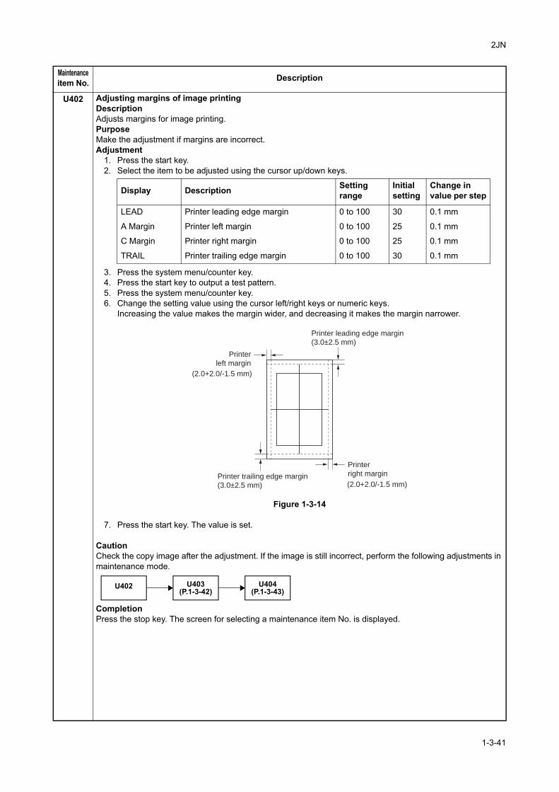
2JN
U402 Adjusting margins of image printingDescriptionAdjusts margins for image printing.PurposeMake the adjustment if margins are incorrect.Adjustment
1. Press the start key.2. Select the item to be adjusted using the cursor up/down keys.
3. Press the system menu/counter key.4. Press the start key to output a test pattern.5. Press the system menu/counter key.6. Change the setting value using the cursor left/right keys or numeric keys.
Increasing the value makes the margin wider, and decreasing it makes the margin narrower.
Figure 1-3-14
7. Press the start key. The value is set.
CautionCheck the copy image after the adjustment. If the image is still incorrect, perform the following adjustments in maintenance mode.
CompletionPress the stop key. The screen for selecting a maintenance item No. is displayed.
Maintenanceitem No. Description
Display Description Settingrange
Initialsetting
Change invalue per step
LEAD Printer leading edge margin 0 to 100 30 0.1 mm
A Margin Printer left margin 0 to 100 25 0.1 mm
C Margin Printer right margin 0 to 100 25 0.1 mm
TRAIL Printer trailing edge margin 0 to 100 30 0.1 mm
(2.0+2.0/-1.5 mm)
(2.0+2.0/-1.5 mm)
Printer leading edge margin
(3.0±2.5 mm)
Printer
left margin
Printer
right marginPrinter trailing edge margin
(3.0±2.5 mm)
U402 U403(P.1-3-42)
U404(P.1-3-43)
1-3-41
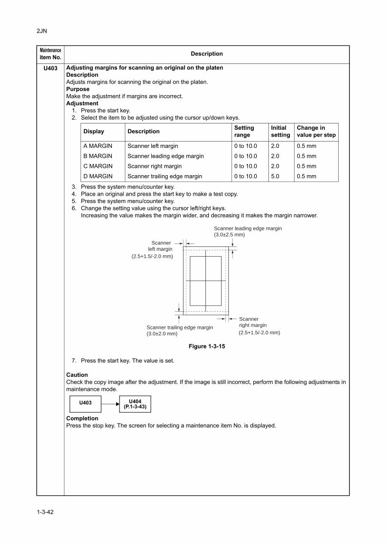
2JN
U403 Adjusting margins for scanning an original on the platenDescriptionAdjusts margins for scanning the original on the platen.PurposeMake the adjustment if margins are incorrect.Adjustment
1. Press the start key.2. Select the item to be adjusted using the cursor up/down keys.
3. Press the system menu/counter key.4. Place an original and press the start key to make a test copy.5. Press the system menu/counter key.6. Change the setting value using the cursor left/right keys.
Increasing the value makes the margin wider, and decreasing it makes the margin narrower.
Figure 1-3-15
7. Press the start key. The value is set.
CautionCheck the copy image after the adjustment. If the image is still incorrect, perform the following adjustments in maintenance mode.
CompletionPress the stop key. The screen for selecting a maintenance item No. is displayed.
Maintenanceitem No. Description
Display Description Settingrange
Initialsetting
Change invalue per step
A MARGIN Scanner left margin 0 to 10.0 2.0 0.5 mm
B MARGIN Scanner leading edge margin 0 to 10.0 2.0 0.5 mm
C MARGIN Scanner right margin 0 to 10.0 2.0 0.5 mm
D MARGIN Scanner trailing edge margin 0 to 10.0 5.0 0.5 mm
(2.5+1.5/-2.0 mm)
(2.5+1.5/-2.0 mm)
Scanner leading edge margin
(3.0±2.5 mm)
Scanner
left margin
Scanner
right marginScanner trailing edge margin
(3.0±2.0 mm)
U403 U404(P.1-3-43)
1-3-42
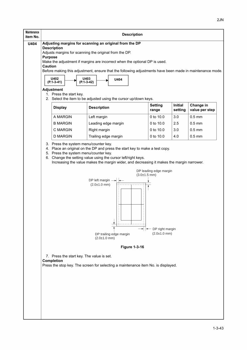
2JN
U404 Adjusting margins for scanning an original from the DPDescriptionAdjusts margins for scanning the original from the DP.PurposeMake the adjustment if margins are incorrect when the optional DP is used.CautionBefore making this adjustment, ensure that the following adjustments have been made in maintenance mode.
Adjustment1. Press the start key.2. Select the item to be adjusted using the cursor up/down keys.
3. Press the system menu/counter key.4. Place an original on the DP and press the start key to make a test copy.5. Press the system menu/counter key.6. Change the setting value using the cursor left/right keys.
Increasing the value makes the margin wider, and decreasing it makes the margin narrower.
Figure 1-3-16
7. Press the start key. The value is set.CompletionPress the stop key. The screen for selecting a maintenance item No. is displayed.
Maintenanceitem No. Description
U403(P.1-3-42)
U402(P.1-3-41)
U404
Display Description Settingrange
Initialsetting
Change invalue per step
A MARGIN Left margin 0 to 10.0 3.0 0.5 mm
B MARGIN Leading edge margin 0 to 10.0 2.5 0.5 mm
C MARGIN Right margin 0 to 10.0 3.0 0.5 mm
D MARGIN Trailing edge margin 0 to 10.0 4.0 0.5 mm
(2.0±1.0 mm)
(2.0±1.0 mm)
DP leading edge margin
(3.0±1.5 mm)
DP left margin
DP right margin
DP trailing edge margin
(2.0±1.0 mm)
1-3-43
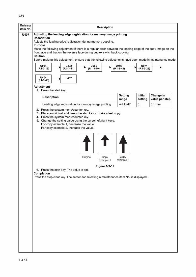
2JN
U407 Adjusting the leading edge registration for memory image printingDescriptionAdjusts the leading edge registration during memory copying.PurposeMake the following adjustment if there is a regular error between the leading edge of the copy image on the front face and that on the reverse face during duplex switchback copying.CautionBefore making this adjustment, ensure that the following adjustments have been made in maintenance mode.
Adjustment1. Press the start key.
2. Press the system menu/counter key.3. Place an original and press the start key to make a test copy.4. Press the system menu/counter key.5. Change the setting value using the cursor left/right keys.
For copy example 1, decrease the value.For copy example 2, increase the value.
Figure 1-3-176. Press the start key. The value is set.
CompletionPress the stop/clear key. The screen for selecting a maintenance item No. is displayed.
Maintenanceitem No. Description
U402(P.1-3-41)
U034(P.1-3-13)
U066(P.1-3-19)
U403(P.1-3-42)
U071(P.1-3-23)
U407U404(P.1-3-43)
Description Settingrange
Initialsetting
Change invalue per step
Leading edge registration for memory image printing -47 to 47 0 0.1 mm
Original Copy
example 1
Copy
example 2
1-3-44
2JN
U411 Adjusting the scanner automaticallyDescriptionUses the adjustment original suppled with DP and automatically adjusts the following items in the scanner and the DP scanning sections.PurposeTo perform automatic adjustment of various items in the scanner and the DP scanning sections.Method
1. Press the start key.
Method: TABLE1. Enter the target values which are shown on the specified original (P/N: 302FZ56990) executing mainte-
nance item U425.2. Set a specified original (P/N: 302FZ56990) on the platen.3. Enter maintenance item U411.4. Select [ADJUST TABLE] using the cursor up/down keys.5. Press the start key. Auto adjustment starts.
When automatic adjustment has normally completed, [OK] is displayed. If a problem occurs during auto adjustment, [NG XX] (XX is replaced by an error code) is displayed and operation stops. Should this happen, determine the details of the problem and either repeat the procedure from the beginning, or adjust the remaining items manually by running the corresponding maintenance items.
6. To return to the screen for selecting an item, press the stop key.
Method: DP1. Select [ADJUST DP] using the cursor up/down keys.2. Set a specified original (P/N: 303LJ57010) in the DP.3. Press the start key. Auto adjustment starts.
When automatic adjustment has normally completed, [OK] is displayed. If a problem occurs during auto adjustment, [NG XX] (XX is replaced by an error code) is displayed and operation stops. Should this happen, determine the details of the problem and either repeat the procedure from the beginning, or adjust the remaining items manually by running the corresponding maintenance items.
4. To return to the screen for selecting an item, press the stop key.
CompletionPress the stop key. The screen for selecting a maintenance item is displayed.
Maintenanceitem No. Description
Display Description Original to be used for adjustment (P/N)
ADJUST TABLE Automatic adjustment in the scanner section: Original size magnification, leading edge timing, center line, input gamma, input gamma in mono-chrome mode and matrix
302FZ56990
ADJUST DP Automatic adjustment in the DP scanning section: Original size magnification, leading edge timing, center line
303LJ57010(Adjustment original suppled with DP)
1-3-45
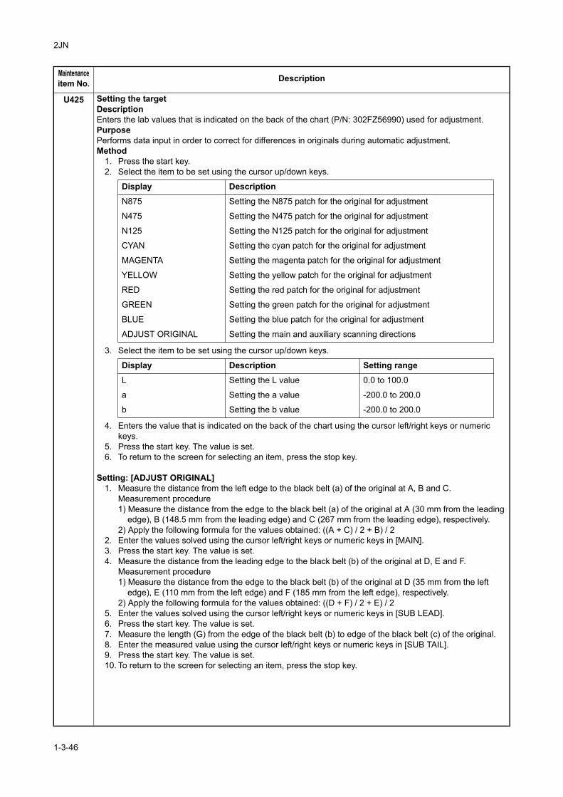
2JN
U425 Setting the targetDescriptionEnters the lab values that is indicated on the back of the chart (P/N: 302FZ56990) used for adjustment.PurposePerforms data input in order to correct for differences in originals during automatic adjustment.Method
1. Press the start key.2. Select the item to be set using the cursor up/down keys.
3. Select the item to be set using the cursor up/down keys.
4. Enters the value that is indicated on the back of the chart using the cursor left/right keys or numeric keys.
5. Press the start key. The value is set.6. To return to the screen for selecting an item, press the stop key.
Setting: [ADJUST ORIGINAL]1. Measure the distance from the left edge to the black belt (a) of the original at A, B and C.
Measurement procedure1) Measure the distance from the edge to the black belt (a) of the original at A (30 mm from the leading
edge), B (148.5 mm from the leading edge) and C (267 mm from the leading edge), respectively.2) Apply the following formula for the values obtained: ((A + C) / 2 + B) / 2
2. Enter the values solved using the cursor left/right keys or numeric keys in [MAIN].3. Press the start key. The value is set.4. Measure the distance from the leading edge to the black belt (b) of the original at D, E and F.
Measurement procedure1) Measure the distance from the edge to the black belt (b) of the original at D (35 mm from the left
edge), E (110 mm from the left edge) and F (185 mm from the left edge), respectively.2) Apply the following formula for the values obtained: ((D + F) / 2 + E) / 2
5. Enter the values solved using the cursor left/right keys or numeric keys in [SUB LEAD].6. Press the start key. The value is set.7. Measure the length (G) from the edge of the black belt (b) to edge of the black belt (c) of the original.8. Enter the measured value using the cursor left/right keys or numeric keys in [SUB TAIL].9. Press the start key. The value is set.10. To return to the screen for selecting an item, press the stop key.
Maintenanceitem No. Description
Display Description
N875 Setting the N875 patch for the original for adjustment
N475 Setting the N475 patch for the original for adjustment
N125 Setting the N125 patch for the original for adjustment
CYAN Setting the cyan patch for the original for adjustment
MAGENTA Setting the magenta patch for the original for adjustment
YELLOW Setting the yellow patch for the original for adjustment
RED Setting the red patch for the original for adjustment
GREEN Setting the green patch for the original for adjustment
BLUE Setting the blue patch for the original for adjustment
ADJUST ORIGINAL Setting the main and auxiliary scanning directions
Display Description Setting range
L Setting the L value 0.0 to 100.0
a Setting the a value -200.0 to 200.0
b Setting the b value -200.0 to 200.0
1-3-46
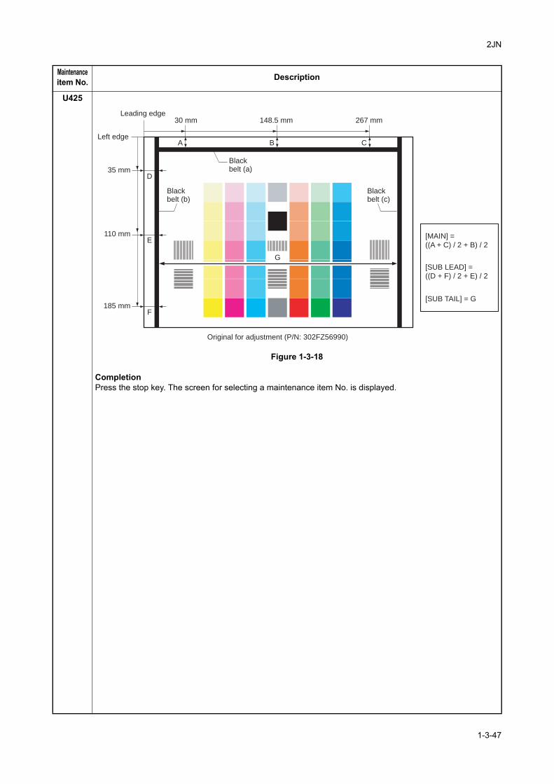
2JN
U425
Figure 1-3-18
CompletionPress the stop key. The screen for selecting a maintenance item No. is displayed.
Maintenanceitem No. Description
30 mm
D
A C
E
F
35 mm
Leading edge
Left edge
Blackbelt (b)
Blackbelt (a)
110 mm
185 mm
148.5 mm 267 mm
Original for adjustment (P/N: 302FZ56990)
B
Blackbelt (c)
G
[MAIN] =
((A + C) / 2 + B) / 2
[SUB LEAD] =
((D + F) / 2 + E) / 2
[SUB TAIL] = G
1-3-47
2JN
U600 Initializing all dataDescriptionInitializes software switches and all data in the backup data on the FAX PWB, according to the destination and OEM.Executes the check of the file system, when abnormality of the file system is detected, initializes the file sys-tem, communication past record and register setting contents.PurposeTo initialize the FAX PWB.Method
1. Press the start key.2. Select [Execute]. The screen for entering the destination code and OEM code is displayed.3. Select [Country Code] and enter a destination code using the numeric keys (refer to the destination
code list on following for the destination code).4. Press the start key.
There is no operation necessary on this screen.The destination code and the OEM code are displayed with the values currently set.
5. Press the start key. Data initialization starts. To cancel data initialization, press the stop key.6. After data initialization, the entered destination, OEM codes and ROM version are displayed. A ROM
version displays three kinds, application, boot, and IPL.
Destination code list
U601 Initializing permanent dataDescriptionInitializes software switches on the FAX PWB according to the destination and OEM.PurposeTo initialize the FAX PWB without changing user registration data.Method
1. Press the start key.2. Select [Execute]. The screen for entering the destination code and OEM code is displayed.3. Select [Country Code] and enter a destination code using the numeric keys (refer to the destination
code list for the destination code).4. Press the start key.
There is no operation necessary on this screen.The destination code and the OEM code are displayed with the values currently set.
5. Press the start key. Data initialization starts. To cancel data initialization, press the back key.6. After data initialization, the entered destination, OEM codes and ROM version are displayed. A ROM
version displays three kinds, application, boot, and IPL.
Maintenanceitem No. Description
Code Destination Code Destination Code Destination
000 Japan 156 Singapore 253 Sweden
009 Australia 159 South Africa France
038 China 169 Thailand Austria
080 Hong Kong 181 U.S.A. Switzerland
084 Indonesia 242 South America Belgium
088 Israel 253 CTR21 (European nations) Denmark
108 Malaysia Italy Finland
126 New Zealand Germany Portugal
136 Peru Spain Ireland
137 Philippines U.K. Norway
152 Saudi Arabia Netherlands 254 Taiwan
1-3-48
2JN
U603 Setting user data 1DescriptionMakes user settings to enable the use of the machine as a fax.PurposeTo be run after installation of the facsimile kit if necessary.Method
1. Press the start key.2. Select [LINE TYPE]. The current setting is displayed in reverse.3. Select the setting using the cursor up/down keys.
Initial setting: DTMF4. Press the start key. The value is set.
CompletionPress the stop key. The screen for selecting a maintenance item No. is displayed.
U604 Setting user data 2DescriptionMakes user settings to enable the use of the machine as a fax.PurposeUse this if the user wishes to adjust the number of rings that occur before the unit switches into fax receiving mode when fax/telephone auto-select is enabled.Method
1. Press the start key. The current setting is displayed.2. Select [RINGS(F/P)#].3. Change the setting using the cursor left/right keys or numeric keys.
If you set this to 0, the unit will start fax reception without any ringing.4. Press the start key. The value is set.
CompletionPress the stop key. The screen for selecting a maintenance item No. is displayed.
U605 Clearing dataDescriptionInitializes data related to the fax transmission such as transmission history.PurposeTo clear the transmission history.Method
1. Press the start key.2. Select [CLEAR COM.REC.].3. Press the start key. Initialization processing starts. When processing is finished, the screen for selecting
a maintenance item No. is displayed.CompletionPress the stop key. The screen for selecting a maintenance item No. is displayed.
Maintenanceitem No. Description
Display Description
DTMF DTMF
10PPS 10 PPS
20PPS 20 PPS
Description Setting range Initial setting
Number of fax/telephone rings 0 to 15 2 (120 V)/1 (220-240 V)
1-3-49
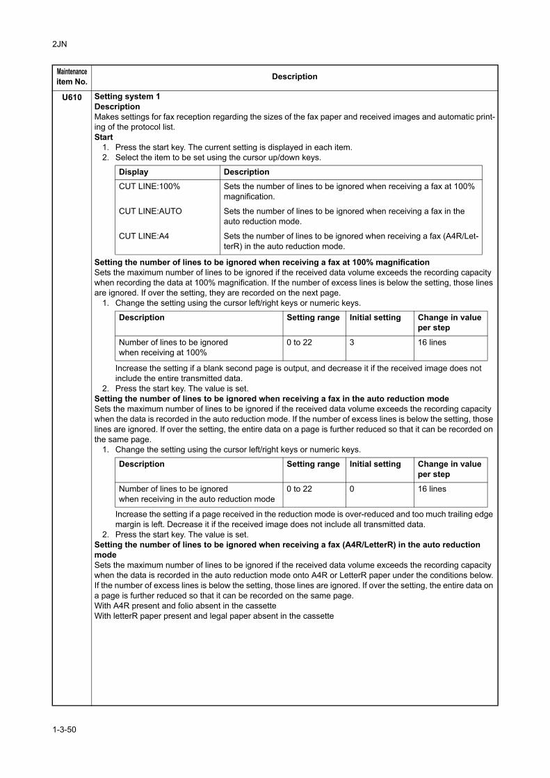
2JN
U610 Setting system 1DescriptionMakes settings for fax reception regarding the sizes of the fax paper and received images and automatic print-ing of the protocol list.Start
1. Press the start key. The current setting is displayed in each item.2. Select the item to be set using the cursor up/down keys.
Setting the number of lines to be ignored when receiving a fax at 100% magnificationSets the maximum number of lines to be ignored if the received data volume exceeds the recording capacity when recording the data at 100% magnification. If the number of excess lines is below the setting, those lines are ignored. If over the setting, they are recorded on the next page.
1. Change the setting using the cursor left/right keys or numeric keys.
Increase the setting if a blank second page is output, and decrease it if the received image does not include the entire transmitted data.
2. Press the start key. The value is set.Setting the number of lines to be ignored when receiving a fax in the auto reduction modeSets the maximum number of lines to be ignored if the received data volume exceeds the recording capacity when the data is recorded in the auto reduction mode. If the number of excess lines is below the setting, those lines are ignored. If over the setting, the entire data on a page is further reduced so that it can be recorded on the same page.
1. Change the setting using the cursor left/right keys or numeric keys.
Increase the setting if a page received in the reduction mode is over-reduced and too much trailing edge margin is left. Decrease it if the received image does not include all transmitted data.
2. Press the start key. The value is set.Setting the number of lines to be ignored when receiving a fax (A4R/LetterR) in the auto reduction modeSets the maximum number of lines to be ignored if the received data volume exceeds the recording capacity when the data is recorded in the auto reduction mode onto A4R or LetterR paper under the conditions below.If the number of excess lines is below the setting, those lines are ignored. If over the setting, the entire data on a page is further reduced so that it can be recorded on the same page.With A4R present and folio absent in the cassetteWith letterR paper present and legal paper absent in the cassette
Maintenanceitem No. Description
Display Description
CUT LINE:100% Sets the number of lines to be ignored when receiving a fax at 100% magnification.
CUT LINE:AUTO Sets the number of lines to be ignored when receiving a fax in the auto reduction mode.
CUT LINE:A4 Sets the number of lines to be ignored when receiving a fax (A4R/Let-terR) in the auto reduction mode.
Description Setting range Initial setting Change in valueper step
Number of lines to be ignoredwhen receiving at 100%
0 to 22 3 16 lines
Description Setting range Initial setting Change in valueper step
Number of lines to be ignoredwhen receiving in the auto reduction mode
0 to 22 0 16 lines
1-3-50
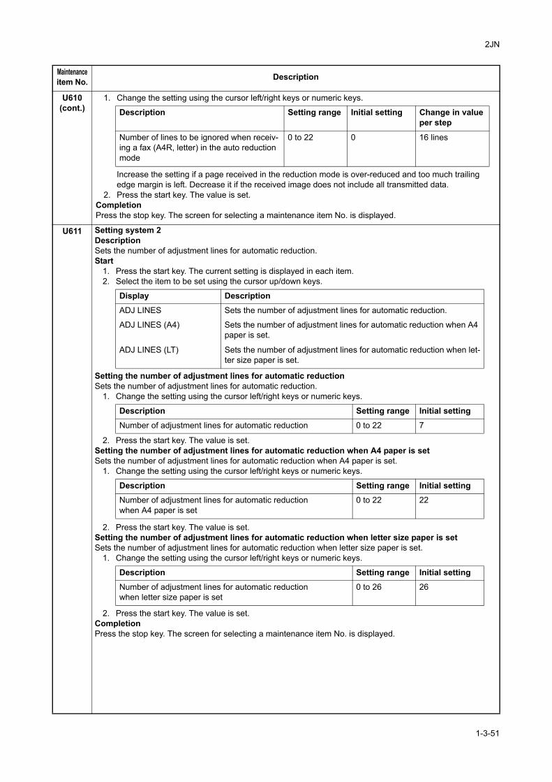
2JN
U610(cont.)
1. Change the setting using the cursor left/right keys or numeric keys.
Increase the setting if a page received in the reduction mode is over-reduced and too much trailing edge margin is left. Decrease it if the received image does not include all transmitted data.
2. Press the start key. The value is set.CompletionPress the stop key. The screen for selecting a maintenance item No. is displayed.
U611 Setting system 2DescriptionSets the number of adjustment lines for automatic reduction.Start
1. Press the start key. The current setting is displayed in each item.2. Select the item to be set using the cursor up/down keys.
Setting the number of adjustment lines for automatic reductionSets the number of adjustment lines for automatic reduction.
1. Change the setting using the cursor left/right keys or numeric keys.
2. Press the start key. The value is set.Setting the number of adjustment lines for automatic reduction when A4 paper is setSets the number of adjustment lines for automatic reduction when A4 paper is set.
1. Change the setting using the cursor left/right keys or numeric keys.
2. Press the start key. The value is set.Setting the number of adjustment lines for automatic reduction when letter size paper is setSets the number of adjustment lines for automatic reduction when letter size paper is set.
1. Change the setting using the cursor left/right keys or numeric keys.
2. Press the start key. The value is set.CompletionPress the stop key. The screen for selecting a maintenance item No. is displayed.
Maintenanceitem No. Description
Description Setting range Initial setting Change in valueper step
Number of lines to be ignored when receiv-ing a fax (A4R, letter) in the auto reduction mode
0 to 22 0 16 lines
Display Description
ADJ LINES Sets the number of adjustment lines for automatic reduction.
ADJ LINES (A4) Sets the number of adjustment lines for automatic reduction when A4 paper is set.
ADJ LINES (LT) Sets the number of adjustment lines for automatic reduction when let-ter size paper is set.
Description Setting range Initial setting
Number of adjustment lines for automatic reduction 0 to 22 7
Description Setting range Initial settingNumber of adjustment lines for automatic reductionwhen A4 paper is set
0 to 22 22
Description Setting range Initial setting
Number of adjustment lines for automatic reductionwhen letter size paper is set
0 to 26 26
1-3-51
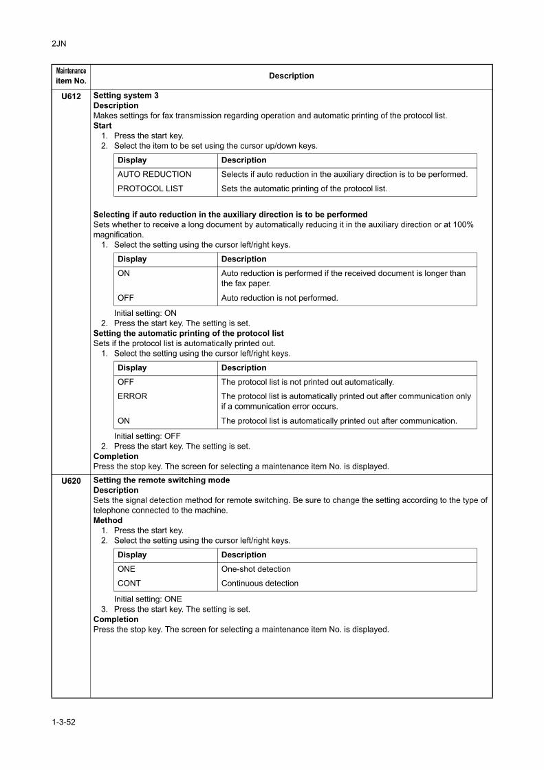
2JN
U612 Setting system 3DescriptionMakes settings for fax transmission regarding operation and automatic printing of the protocol list.Start
1. Press the start key.2. Select the item to be set using the cursor up/down keys.
Selecting if auto reduction in the auxiliary direction is to be performedSets whether to receive a long document by automatically reducing it in the auxiliary direction or at 100% magnification.
1. Select the setting using the cursor left/right keys.
Initial setting: ON2. Press the start key. The setting is set.
Setting the automatic printing of the protocol listSets if the protocol list is automatically printed out.
1. Select the setting using the cursor left/right keys.
Initial setting: OFF 2. Press the start key. The setting is set.
CompletionPress the stop key. The screen for selecting a maintenance item No. is displayed.
U620 Setting the remote switching modeDescriptionSets the signal detection method for remote switching. Be sure to change the setting according to the type of telephone connected to the machine.Method
1. Press the start key.2. Select the setting using the cursor left/right keys.
Initial setting: ONE 3. Press the start key. The setting is set.
CompletionPress the stop key. The screen for selecting a maintenance item No. is displayed.
Maintenanceitem No. Description
Display Description
AUTO REDUCTION Selects if auto reduction in the auxiliary direction is to be performed.
PROTOCOL LIST Sets the automatic printing of the protocol list.
Display Description
ON Auto reduction is performed if the received document is longer than the fax paper.
OFF Auto reduction is not performed.
Display Description
OFF The protocol list is not printed out automatically.
ERROR The protocol list is automatically printed out after communication only if a communication error occurs.
ON The protocol list is automatically printed out after communication.
Display Description
ONE One-shot detection
CONT Continuous detection
1-3-52
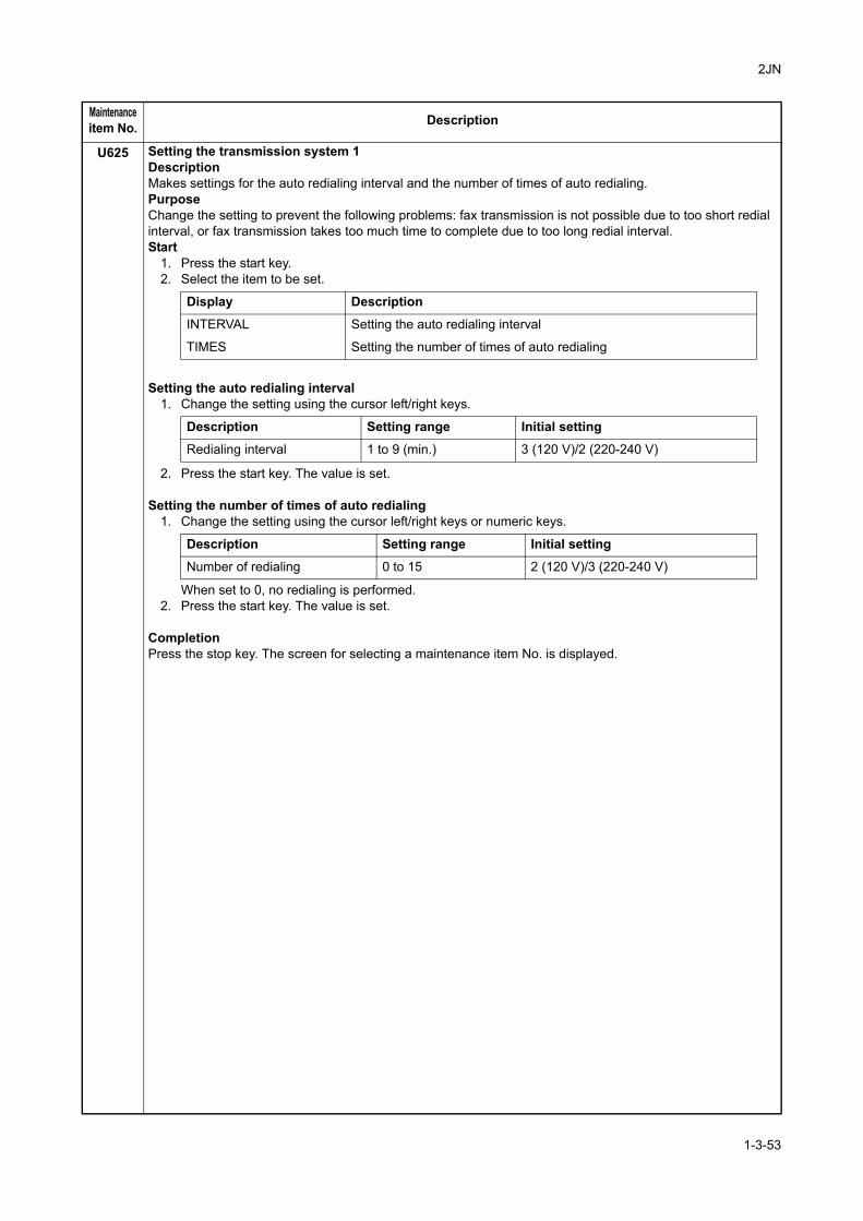
2JN
U625 Setting the transmission system 1DescriptionMakes settings for the auto redialing interval and the number of times of auto redialing.PurposeChange the setting to prevent the following problems: fax transmission is not possible due to too short redial interval, or fax transmission takes too much time to complete due to too long redial interval.Start
1. Press the start key.2. Select the item to be set.
Setting the auto redialing interval1. Change the setting using the cursor left/right keys.
2. Press the start key. The value is set.
Setting the number of times of auto redialing1. Change the setting using the cursor left/right keys or numeric keys.
When set to 0, no redialing is performed.2. Press the start key. The value is set.
CompletionPress the stop key. The screen for selecting a maintenance item No. is displayed.
Maintenanceitem No. Description
Display Description
INTERVAL Setting the auto redialing interval
TIMES Setting the number of times of auto redialing
Description Setting range Initial setting
Redialing interval 1 to 9 (min.) 3 (120 V)/2 (220-240 V)
Description Setting range Initial setting
Number of redialing 0 to 15 2 (120 V)/3 (220-240 V)
1-3-53
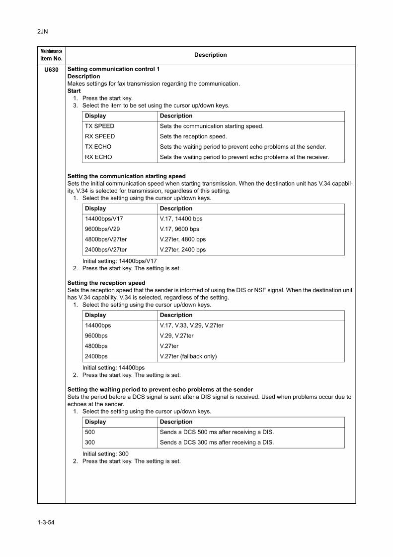
2JN
U630 Setting communication control 1DescriptionMakes settings for fax transmission regarding the communication.Start
1. Press the start key.3. Select the item to be set using the cursor up/down keys.
Setting the communication starting speedSets the initial communication speed when starting transmission. When the destination unit has V.34 capabil-ity, V.34 is selected for transmission, regardless of this setting.
1. Select the setting using the cursor up/down keys.
Initial setting: 14400bps/V172. Press the start key. The setting is set.
Setting the reception speedSets the reception speed that the sender is informed of using the DIS or NSF signal. When the destination unit has V.34 capability, V.34 is selected, regardless of the setting.
1. Select the setting using the cursor up/down keys.
Initial setting: 14400bps2. Press the start key. The setting is set.
Setting the waiting period to prevent echo problems at the senderSets the period before a DCS signal is sent after a DIS signal is received. Used when problems occur due to echoes at the sender.
1. Select the setting using the cursor up/down keys.
Initial setting: 3002. Press the start key. The setting is set.
Maintenanceitem No. Description
Display Description
TX SPEED Sets the communication starting speed.
RX SPEED Sets the reception speed.
TX ECHO Sets the waiting period to prevent echo problems at the sender.
RX ECHO Sets the waiting period to prevent echo problems at the receiver.
Display Description
14400bps/V17 V.17, 14400 bps
9600bps/V29 V.17, 9600 bps
4800bps/V27ter V.27ter, 4800 bps
2400bps/V27ter V.27ter, 2400 bps
Display Description
14400bps V.17, V.33, V.29, V.27ter
9600bps V.29, V.27ter
4800bps V.27ter
2400bps V.27ter (fallback only)
Display Description
500 Sends a DCS 500 ms after receiving a DIS.
300 Sends a DCS 300 ms after receiving a DIS.
1-3-54
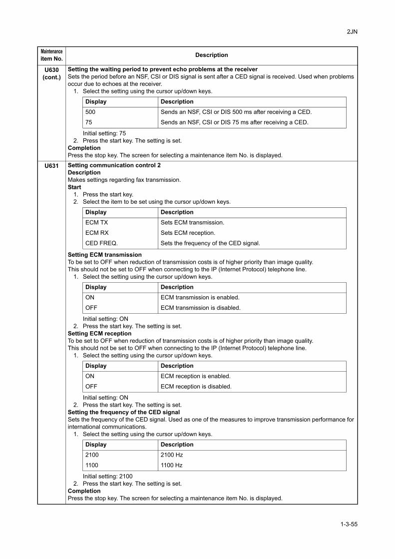
2JN
U630(cont.)
Setting the waiting period to prevent echo problems at the receiverSets the period before an NSF, CSI or DIS signal is sent after a CED signal is received. Used when problems occur due to echoes at the receiver.
1. Select the setting using the cursor up/down keys.
Initial setting: 752. Press the start key. The setting is set.
CompletionPress the stop key. The screen for selecting a maintenance item No. is displayed.
U631 Setting communication control 2DescriptionMakes settings regarding fax transmission.Start
1. Press the start key.2. Select the item to be set using the cursor up/down keys.
Setting ECM transmissionTo be set to OFF when reduction of transmission costs is of higher priority than image quality.This should not be set to OFF when connecting to the IP (Internet Protocol) telephone line.
1. Select the setting using the cursor up/down keys.
Initial setting: ON2. Press the start key. The setting is set.
Setting ECM receptionTo be set to OFF when reduction of transmission costs is of higher priority than image quality.This should not be set to OFF when connecting to the IP (Internet Protocol) telephone line.
1. Select the setting using the cursor up/down keys.
Initial setting: ON2. Press the start key. The setting is set.
Setting the frequency of the CED signalSets the frequency of the CED signal. Used as one of the measures to improve transmission performance for international communications.
1. Select the setting using the cursor up/down keys.
Initial setting: 21002. Press the start key. The setting is set.
CompletionPress the stop key. The screen for selecting a maintenance item No. is displayed.
Maintenanceitem No. Description
Display Description
500 Sends an NSF, CSI or DIS 500 ms after receiving a CED.
75 Sends an NSF, CSI or DIS 75 ms after receiving a CED.
Display Description
ECM TX Sets ECM transmission.
ECM RX Sets ECM reception.
CED FREQ. Sets the frequency of the CED signal.
Display Description
ON ECM transmission is enabled.
OFF ECM transmission is disabled.
Display Description
ON ECM reception is enabled.
OFF ECM reception is disabled.
Display Description
2100 2100 Hz
1100 1100 Hz
1-3-55
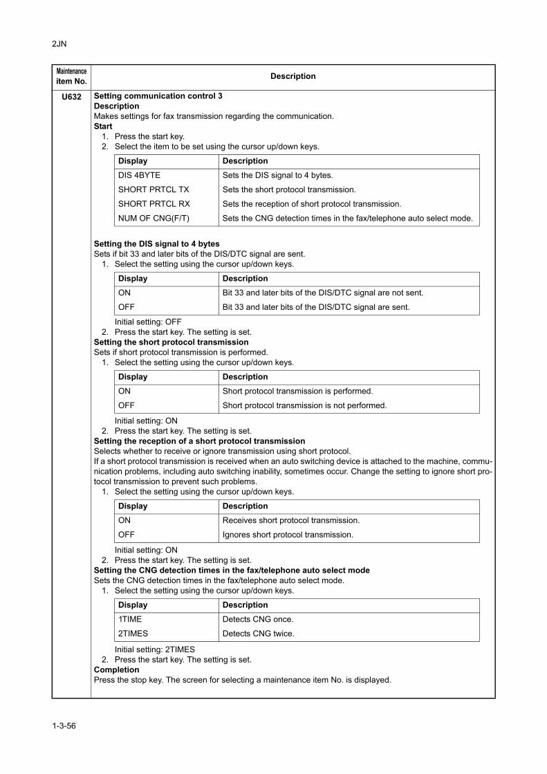
2JN
U632 Setting communication control 3DescriptionMakes settings for fax transmission regarding the communication.Start
1. Press the start key.2. Select the item to be set using the cursor up/down keys.
Setting the DIS signal to 4 bytesSets if bit 33 and later bits of the DIS/DTC signal are sent.
1. Select the setting using the cursor up/down keys.
Initial setting: OFF2. Press the start key. The setting is set.
Setting the short protocol transmissionSets if short protocol transmission is performed.
1. Select the setting using the cursor up/down keys.
Initial setting: ON2. Press the start key. The setting is set.
Setting the reception of a short protocol transmissionSelects whether to receive or ignore transmission using short protocol.If a short protocol transmission is received when an auto switching device is attached to the machine, commu-nication problems, including auto switching inability, sometimes occur. Change the setting to ignore short pro-tocol transmission to prevent such problems.
1. Select the setting using the cursor up/down keys.
Initial setting: ON2. Press the start key. The setting is set.
Setting the CNG detection times in the fax/telephone auto select modeSets the CNG detection times in the fax/telephone auto select mode.
1. Select the setting using the cursor up/down keys.
Initial setting: 2TIMES2. Press the start key. The setting is set.
CompletionPress the stop key. The screen for selecting a maintenance item No. is displayed.
Maintenanceitem No. Description
Display Description
DIS 4BYTE Sets the DIS signal to 4 bytes.
SHORT PRTCL TX Sets the short protocol transmission.
SHORT PRTCL RX Sets the reception of short protocol transmission.
NUM OF CNG(F/T) Sets the CNG detection times in the fax/telephone auto select mode.
Display DescriptionON Bit 33 and later bits of the DIS/DTC signal are not sent.
OFF Bit 33 and later bits of the DIS/DTC signal are sent.
Display Description
ON Short protocol transmission is performed.
OFF Short protocol transmission is not performed.
Display DescriptionON Receives short protocol transmission.
OFF Ignores short protocol transmission.
Display Description
1TIME Detects CNG once.
2TIMES Detects CNG twice.
1-3-56
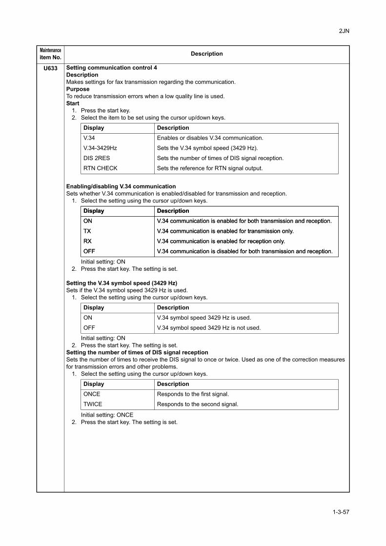
2JN
U633 Setting communication control 4DescriptionMakes settings for fax transmission regarding the communication.PurposeTo reduce transmission errors when a low quality line is used.Start
1. Press the start key.2. Select the item to be set using the cursor up/down keys.
Enabling/disabling V.34 communicationSets whether V.34 communication is enabled/disabled for transmission and reception.
1. Select the setting using the cursor up/down keys.
Initial setting: ON2. Press the start key. The setting is set.
Setting the V.34 symbol speed (3429 Hz)Sets if the V.34 symbol speed 3429 Hz is used.
1. Select the setting using the cursor up/down keys.
Initial setting: ON2. Press the start key. The setting is set.
Setting the number of times of DIS signal receptionSets the number of times to receive the DIS signal to once or twice. Used as one of the correction measures for transmission errors and other problems.
1. Select the setting using the cursor up/down keys.
Initial setting: ONCE2. Press the start key. The setting is set.
Maintenanceitem No. Description
Display Description
V.34 Enables or disables V.34 communication.
V.34-3429Hz Sets the V.34 symbol speed (3429 Hz).
DIS 2RES Sets the number of times of DIS signal reception.
RTN CHECK Sets the reference for RTN signal output.
Display Description
ON V.34 communication is enabled for both transmission and reception.
TX V.34 communication is enabled for transmission only.
RX V.34 communication is enabled for reception only.
OFF V.34 communication is disabled for both transmission and reception.
Display Description
ON V.34 communication is enabled for both transmission and reception.
TX V.34 communication is enabled for transmission only.
RX V.34 communication is enabled for reception only.
OFF V.34 communication is disabled for both transmission and reception.
Display Description
ON V.34 symbol speed 3429 Hz is used.
OFF V.34 symbol speed 3429 Hz is not used.
Display Description
ONCE Responds to the first signal.
TWICE Responds to the second signal.
1-3-57
2JN
U633(cont.)
Setting the reference for RTN signal outputSets the error line rate as the reference for RTN signal output. If transmission errors occur frequently due to the quality of the line, they can be reduced by lowering this setting.
1. Select the setting using the cursor up/down keys.
Initial setting: 15%2. Press the start key. The setting is set.
CompletionPress the stop key. The screen for selecting a maintenance item No. is displayed.
U634 Setting communication control 5DescriptionSets the maximum number of error bytes judged acceptable when receiving a TCF signal. Used as a measure to ease transmission conditions if transmission errors occur.Method
1. Press the start key.2. Change the setting using the cursor left/right keys or numeric keys.
3. Press the start key. The value is set.CompletionPress the stop key. The screen for selecting a maintenance item No. is displayed.
U640 Setting communication time 1DescriptionSets the detection time when one-shot detection is selected for remote switching. (This setting item will be dis-played, but the setting made is ineffective.)Sets the detection time when continuous detection is selected for remote switching. (This setting item will be displayed, but the setting made is ineffective.)Method
1. Press the start key.2. Select the item to be set using the cursor up/down keys.
3. Change the setting using the cursor left/right keys or numeric keys.4. Press the start key. The value is set.
CompletionPress the stop key. The screen for selecting a maintenance item No. is displayed.
Maintenanceitem No. Description
Display Description
5% Error line rate of 5%
10% Error line rate of 10%
15% Error line rate of 15%
20% Error line rate of 20%
Description Setting range Initial setting
Number of allowed error bytes when detecting TCF 0 to 255 0
Display Description Settingrange
Initialsetting
TIME (ONE) Sets the one-shot detection time for remote switching.
0 to 255 7
TIME (CONT) Sets the continuous detection time for remote switching.
0 to 255 80
1-3-58
2JN
U641 Setting communication time 2DescriptionSets the time-out time for fax transmission.PurposeTo improve transmission performance for international communications mainly.Start
1. Press the start key.2. Select the item to be set using the cursor up/down keys.
Setting the T0 time-out timeSets the time before detecting a CED or DIS signal after a dialing signal is sent.Depending on the quality of the exchange, or when the auto select function is selected at the destination unit, a line can be disconnected. Change the setting to prevent this problem.
1. Change the setting using the cursor left/right keys.
2. Press the start key. The value is set.
Setting the T1 time-out timeSets the time before receiving the correct signal after call reception. No change is necessary for this mainte-nance item.
1. Change the setting using the cursor left/right keys.
2. Press the start key. The value is set.3. To return to the screen for selecting an item, press the stop/clear key.
Setting the T2 time-out timeThe T2 time-out time decides the following.From CFR signal output to image data receptionFrom image data reception to the next signal receptionIn ECM, from RNR signal detection to the next signal reception
1. Change the setting using the cursor left/right keys.
2. Press the start key. The value is set.
Maintenanceitem No. Description
Display Description
T0 TIME OUT Sets the T0 time-out time.
T1 TIME OUT Sets the T1 time-out time.
T2 TIME OUT Sets the T2 time-out time.
Ta TIME OUT Sets the Ta time-out time.
Tb1 TIME OUT Sets the Tb1 time-out time.
Tb2 TIME OUT Sets the Tb2 time-out time.
Tc TIME OUT Sets the Tc time-out time.
Td TIME OUT Sets the Td time-out time.
Description Setting range Initial settingT0 time-out time 30 to 90 s 56
Description Setting range Initial setting
T1 time-out time 30 to 90 s 36
Description Setting range Initial setting Change in value per step
T2 time-out time 1 to 255 69 100 ms
1-3-59
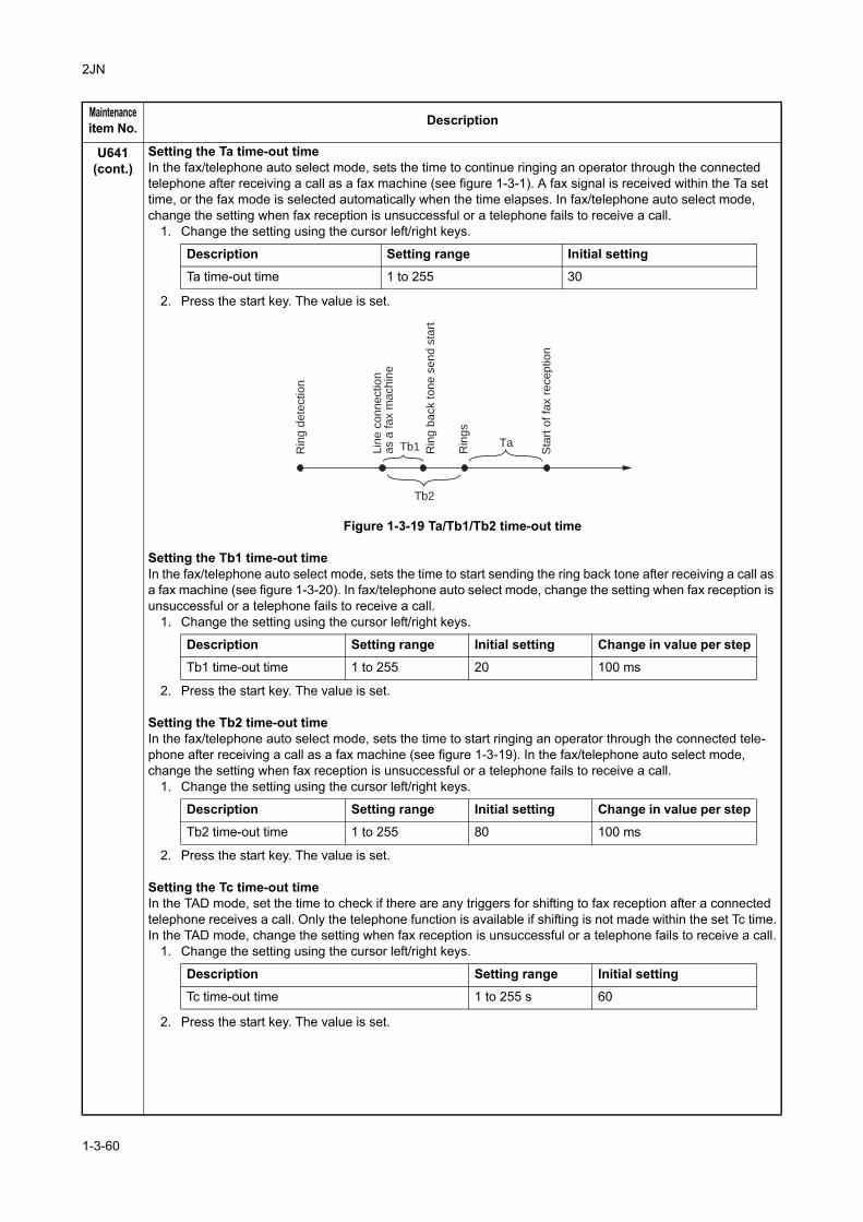
2JN
U641(cont.)
Setting the Ta time-out timeIn the fax/telephone auto select mode, sets the time to continue ringing an operator through the connected telephone after receiving a call as a fax machine (see figure 1-3-1). A fax signal is received within the Ta set time, or the fax mode is selected automatically when the time elapses. In fax/telephone auto select mode, change the setting when fax reception is unsuccessful or a telephone fails to receive a call.
1. Change the setting using the cursor left/right keys.
2. Press the start key. The value is set.
Figure 1-3-19 Ta/Tb1/Tb2 time-out time
Setting the Tb1 time-out timeIn the fax/telephone auto select mode, sets the time to start sending the ring back tone after receiving a call as a fax machine (see figure 1-3-20). In fax/telephone auto select mode, change the setting when fax reception is unsuccessful or a telephone fails to receive a call.
1. Change the setting using the cursor left/right keys.
2. Press the start key. The value is set.
Setting the Tb2 time-out timeIn the fax/telephone auto select mode, sets the time to start ringing an operator through the connected tele-phone after receiving a call as a fax machine (see figure 1-3-19). In the fax/telephone auto select mode, change the setting when fax reception is unsuccessful or a telephone fails to receive a call.
1. Change the setting using the cursor left/right keys.
2. Press the start key. The value is set.
Setting the Tc time-out timeIn the TAD mode, set the time to check if there are any triggers for shifting to fax reception after a connected telephone receives a call. Only the telephone function is available if shifting is not made within the set Tc time.In the TAD mode, change the setting when fax reception is unsuccessful or a telephone fails to receive a call.
1. Change the setting using the cursor left/right keys.
2. Press the start key. The value is set.
Maintenanceitem No. Description
Description Setting range Initial setting
Ta time-out time 1 to 255 30
Ta
Tb2
Tb1Rin
g d
ete
ctio
n
Lin
e c
on
ne
ctio
n
as a
fa
x m
ach
ine
Rin
gs
Rin
g b
ack t
on
e s
en
d s
tart
Sta
rt o
f fa
x r
ece
ptio
n
Description Setting range Initial setting Change in value per step
Tb1 time-out time 1 to 255 20 100 ms
Description Setting range Initial setting Change in value per step
Tb2 time-out time 1 to 255 80 100 ms
Description Setting range Initial setting
Tc time-out time 1 to 255 s 60
1-3-60
2JN
U641(cont.)
Setting the Td time-out timeSets the length of the time required to determine silent status (fax), one of the triggers for Tc time check. In the TAD mode, change the setting when fax reception is unsuccessful or a telephone fails to receive a call. Be sure not to set it too short; otherwise, the mode may be shifted to fax while the unit is being used as a tele-phone.
1. Change the setting using the cursor left/right keys.
2. Press the start key. The value is set.CompletionPress the stop key. The screen for selecting a maintenance item No. is displayed.
U650 Setting modem 1DescriptionSets the G3 cable equalizer.Sets the modem detection level.Start
1. Press the start key.2. Select the item to be set using the cursor up/down keys.
Setting the G3 transmission cable equalizerPerform the following adjustment to make the equalizer compatible with the line characteristics.
1. Select [0dB], [4dB], [8dB] or [12dB] using the cursor up/down keys.Initial setting: 0dB
2. Press the start key. The setting is set.
Setting the G3 reception cable equalizerPerform the following adjustment to make the equalizer compatible with the line characteristics.
1. Select [0dB], [4dB], [8dB] or [12dB] using the cursor up/down keys.Initial setting: 0dB
2. Press the start key. The setting is set.
Setting the modem detection levelTo improve the transmission performance when a low quality line is used.
1. Select [33dBm], [38dBm], [43dBm] or [48dBm] using the cursor up/down keys.Initial setting: 43dBm
2. Press the start key. The setting is set.
CompletionPress the stop key. The screen for selecting a maintenance item No. is displayed.
Maintenanceitem No. Description
Description Setting range Initial setting
Td time-out time 1 to 255 s 9 (120 V)/6 (220-240 V)
Display Description
REG. G3 TX EQR Sets the G3 transmission cable equalizer.
REG. G3 RX EQR Sets the G3 reception cable equalizer.
RX MODEM LEVEL Sets the modem detection level.
1-3-61
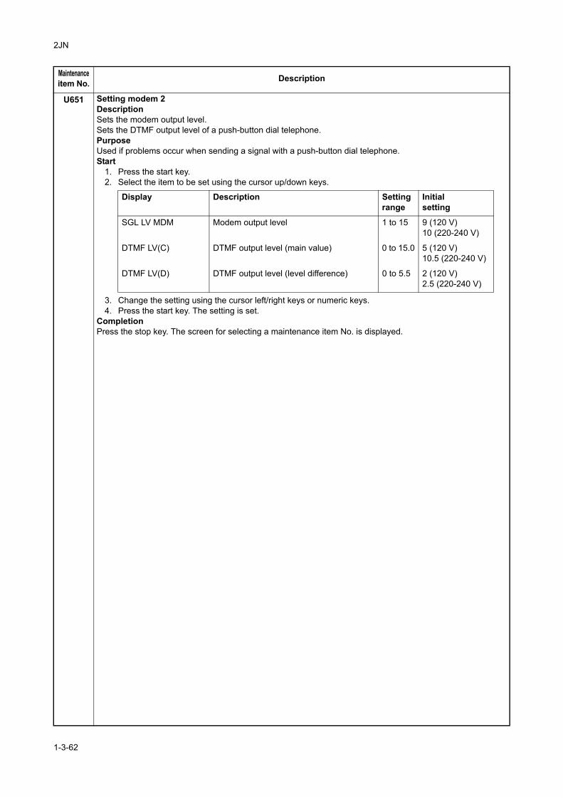
2JN
U651 Setting modem 2DescriptionSets the modem output level.Sets the DTMF output level of a push-button dial telephone.PurposeUsed if problems occur when sending a signal with a push-button dial telephone.Start
1. Press the start key.2. Select the item to be set using the cursor up/down keys.
3. Change the setting using the cursor left/right keys or numeric keys.4. Press the start key. The setting is set.
CompletionPress the stop key. The screen for selecting a maintenance item No. is displayed.
Maintenanceitem No. Description
Display Description Settingrange
Initialsetting
SGL LV MDM Modem output level 1 to 15 9 (120 V)10 (220-240 V)
DTMF LV(C) DTMF output level (main value) 0 to 15.0 5 (120 V)10.5 (220-240 V)
DTMF LV(D) DTMF output level (level difference) 0 to 5.5 2 (120 V)2.5 (220-240 V)
1-3-62
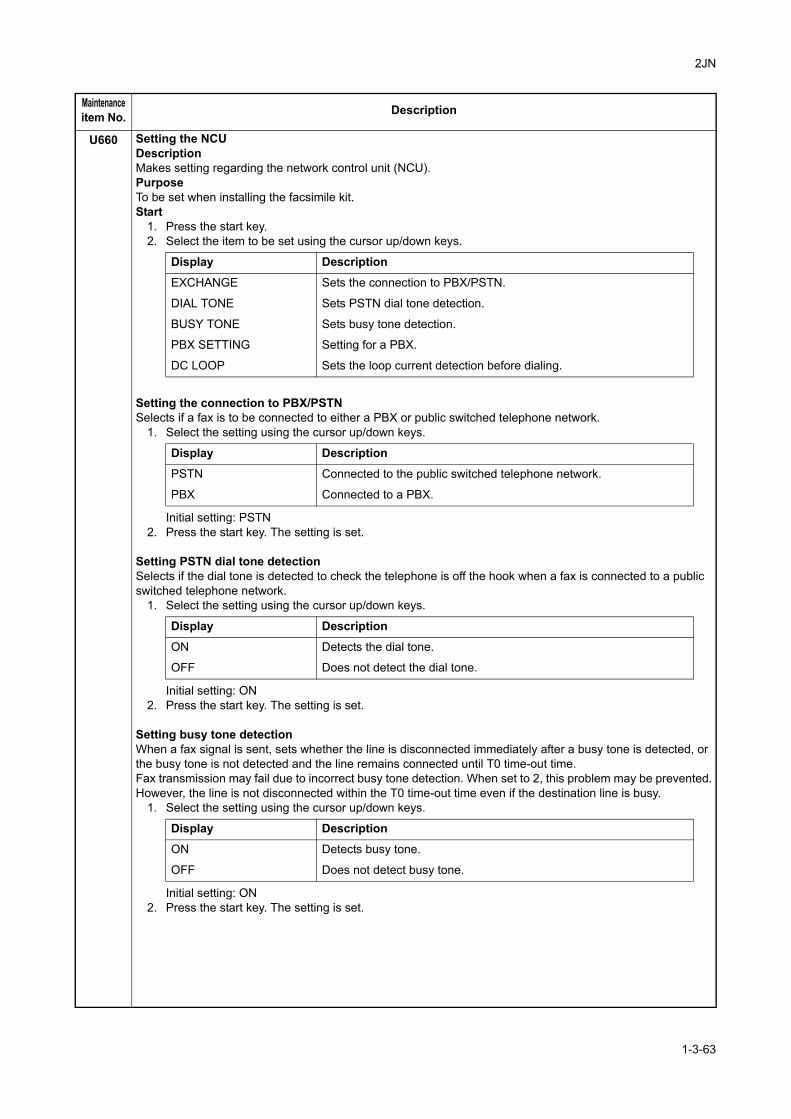
2JN
U660 Setting the NCUDescriptionMakes setting regarding the network control unit (NCU).PurposeTo be set when installing the facsimile kit.Start
1. Press the start key.2. Select the item to be set using the cursor up/down keys.
Setting the connection to PBX/PSTNSelects if a fax is to be connected to either a PBX or public switched telephone network.
1. Select the setting using the cursor up/down keys.
Initial setting: PSTN2. Press the start key. The setting is set.
Setting PSTN dial tone detectionSelects if the dial tone is detected to check the telephone is off the hook when a fax is connected to a public switched telephone network.
1. Select the setting using the cursor up/down keys.
Initial setting: ON2. Press the start key. The setting is set.
Setting busy tone detectionWhen a fax signal is sent, sets whether the line is disconnected immediately after a busy tone is detected, or the busy tone is not detected and the line remains connected until T0 time-out time.Fax transmission may fail due to incorrect busy tone detection. When set to 2, this problem may be prevented.However, the line is not disconnected within the T0 time-out time even if the destination line is busy.
1. Select the setting using the cursor up/down keys.
Initial setting: ON2. Press the start key. The setting is set.
Maintenanceitem No. Description
Display Description
EXCHANGE Sets the connection to PBX/PSTN.
DIAL TONE Sets PSTN dial tone detection.
BUSY TONE Sets busy tone detection.
PBX SETTING Setting for a PBX.
DC LOOP Sets the loop current detection before dialing.
Display Description
PSTN Connected to the public switched telephone network.
PBX Connected to a PBX.
Display Description
ON Detects the dial tone.
OFF Does not detect the dial tone.
Display Description
ON Detects busy tone.
OFF Does not detect busy tone.
1-3-63
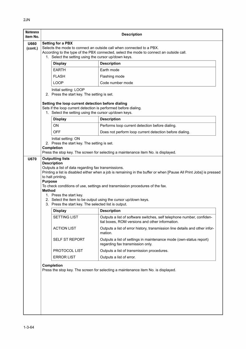
2JN
U660(cont.)
Setting for a PBXSelects the mode to connect an outside call when connected to a PBX.According to the type of the PBX connected, select the mode to connect an outside call.
1. Select the setting using the cursor up/down keys.
Initial setting: LOOP2. Press the start key. The setting is set.
Setting the loop current detection before dialingSets if the loop current detection is performed before dialing.
1. Select the setting using the cursor up/down keys.
Initial setting: ON2. Press the start key. The setting is set.
CompletionPress the stop key. The screen for selecting a maintenance item No. is displayed.
U670 Outputting listsDescriptionOutputs a list of data regarding fax transmissions.Printing a list is disabled either when a job is remaining in the buffer or when [Pause All Print Jobs] is pressed to halt printing.PurposeTo check conditions of use, settings and transmission procedures of the fax.Method
1. Press the start key.2. Select the item to be output using the cursor up/down keys.3. Press the start key. The selected list is output.
CompletionPress the stop key. The screen for selecting a maintenance item No. is displayed.
Maintenanceitem No. Description
Display Description
EARTH Earth mode
FLASH Flashing mode
LOOP Code number mode
Display Description
ON Performs loop current detection before dialing.
OFF Does not perform loop current detection before dialing.
Display DescriptionSETTING LIST Outputs a list of software switches, self telephone number, confiden-
tial boxes, ROM versions and other information.
ACTION LIST Outputs a list of error history, transmission line details and other infor-mation.
SELF ST REPORT Outputs a list of settings in maintenance mode (own-status report) regarding fax transmission only.
PROTOCOL LIST Outputs a list of transmission procedures.
ERROR LIST Outputs a list of error.
1-3-64
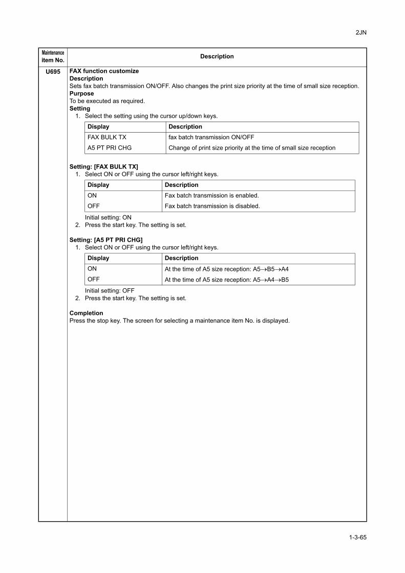
2JN
U695 FAX function customizeDescriptionSets fax batch transmission ON/OFF. Also changes the print size priority at the time of small size reception.PurposeTo be executed as required.Setting
1. Select the setting using the cursor up/down keys.
Setting: [FAX BULK TX]1. Select ON or OFF using the cursor left/right keys.
Initial setting: ON2. Press the start key. The setting is set.
Setting: [A5 PT PRI CHG]1. Select ON or OFF using the cursor left/right keys.
Initial setting: OFF2. Press the start key. The setting is set.
CompletionPress the stop key. The screen for selecting a maintenance item No. is displayed.
Maintenanceitem No. Description
Display Description
FAX BULK TX fax batch transmission ON/OFF
A5 PT PRI CHG Change of print size priority at the time of small size reception
Display Description
ON Fax batch transmission is enabled.
OFF Fax batch transmission is disabled.
Display Description
ON At the time of A5 size reception: A5→B5→A4OFF At the time of A5 size reception: A5→A4→B5
1-3-65
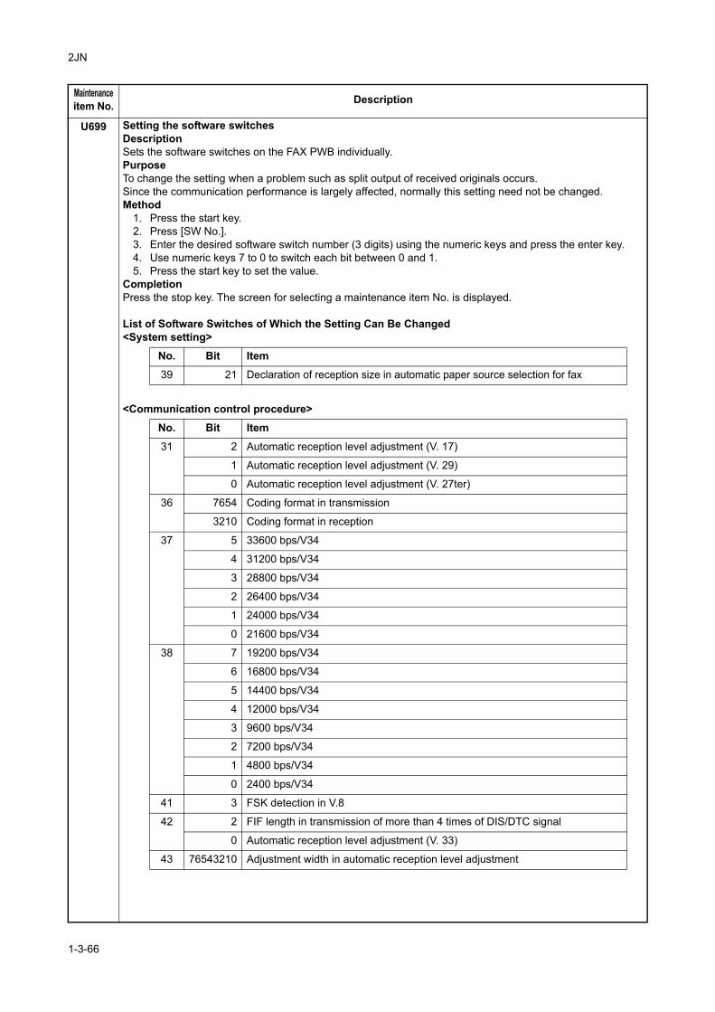
2JN
U699 Setting the software switchesDescriptionSets the software switches on the FAX PWB individually.PurposeTo change the setting when a problem such as split output of received originals occurs. Since the communication performance is largely affected, normally this setting need not be changed.Method
1. Press the start key.2. Press [SW No.].3. Enter the desired software switch number (3 digits) using the numeric keys and press the enter key.4. Use numeric keys 7 to 0 to switch each bit between 0 and 1.5. Press the start key to set the value.
CompletionPress the stop key. The screen for selecting a maintenance item No. is displayed.
List of Software Switches of Which the Setting Can Be Changed<System setting>
<Communication control procedure>
Maintenanceitem No. Description
No. Bit Item
39 21 Declaration of reception size in automatic paper source selection for fax
No. Bit Item
31 2 Automatic reception level adjustment (V. 17)
1 Automatic reception level adjustment (V. 29)
0 Automatic reception level adjustment (V. 27ter)
36 7654 Coding format in transmission
3210 Coding format in reception
37 5 33600 bps/V34
4 31200 bps/V34
3 28800 bps/V34
2 26400 bps/V34
1 24000 bps/V34
0 21600 bps/V34
38 7 19200 bps/V34
6 16800 bps/V34
5 14400 bps/V34
4 12000 bps/V34
3 9600 bps/V34
2 7200 bps/V34
1 4800 bps/V34
0 2400 bps/V34
41 3 FSK detection in V.8
42 2 FIF length in transmission of more than 4 times of DIS/DTC signal
0 Automatic reception level adjustment (V. 33)
43 76543210 Adjustment width in automatic reception level adjustment
1-3-66
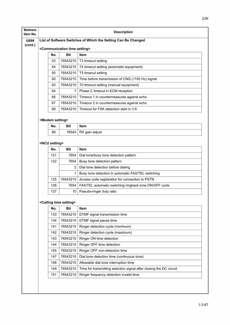
2JN
U699(cont.)
List of Software Switches of Which the Setting Can Be Changed
<Communication time setting>
<Modem setting>
<NCU setting>
<Calling time setting>
Maintenanceitem No. Description
No. Bit Item
53 76543210 T3 timeout setting
54 76543210 T4 timeout setting (automatic equipment)
55 76543210 T5 timeout setting
60 76543210 Time before transmission of CNG (1100 Hz) signal
63 76543210 T0 timeout setting (manual equipment)
64 7 Phase C timeout in ECM reception
66 76543210 Timeout 1 in countermeasures against echo
67 76543210 Timeout 2 in countermeasures against echo
68 76543210 Timeout for FSK detection start in V.8
No. Bit Item
89 76543 RX gain adjust
No. Bit Item
121 7654 Dial tone/busy tone detection pattern
122 7654 Busy tone detection pattern
2 Dial tone detection before dialing
1 Busy tone detection in automatic FAX/TEL switching
125 76543210 Access code registration for connection to PSTN
126 7654 FAX/TEL automatic switching ringback tone ON/OFF cycle
127 10 Pseudo-ringer duty ratio
No. Bit Item
133 76543210 DTMF signal transmission time
134 76543210 DTMF signal pause time
141 76543210 Ringer detection cycle (minimum)
142 76543210 Ringer detection cycle (maximum)
143 76543210 Ringer ON time detection
144 76543210 Ringer OFF time detection
145 76543210 Ringer OFF non-detection time
147 76543210 Dial tone detection time (continuous tone)
148 76543210 Allowable dial tone interruption time
149 76543210 Time for transmitting selection signal after closing the DC circuit
151 76543210 Ringer frequency detection invalid time
1-3-67
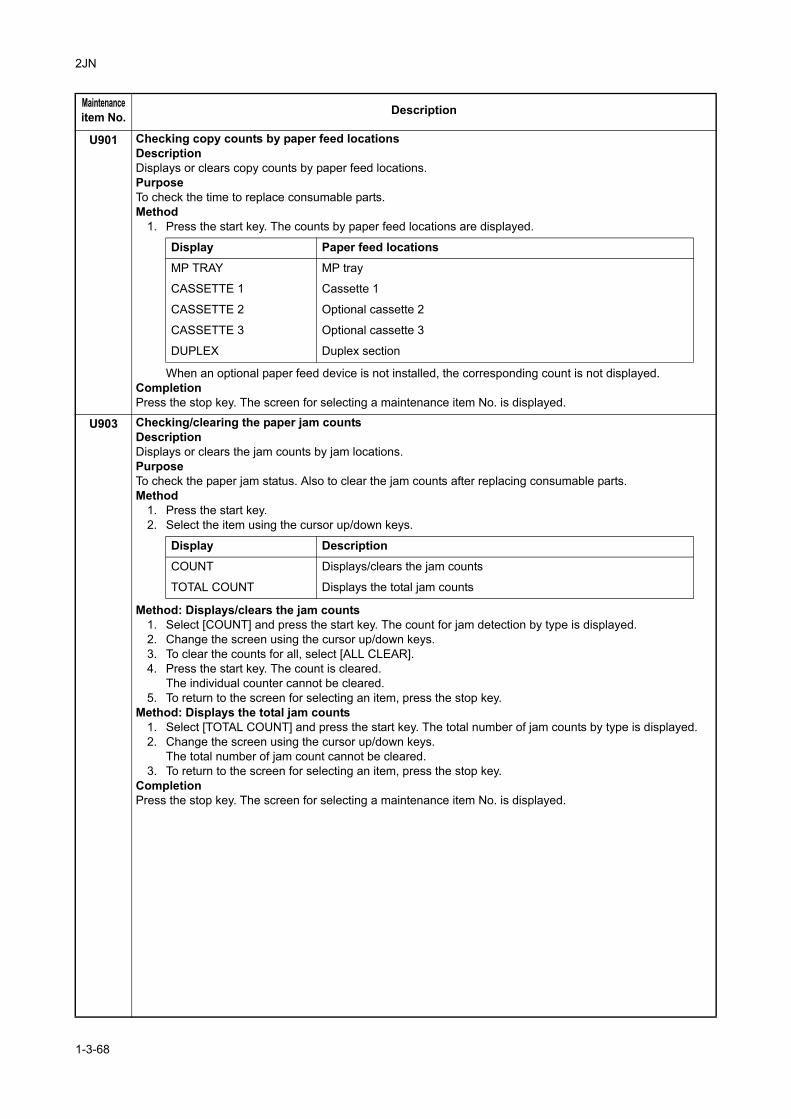
2JN
U901 Checking copy counts by paper feed locationsDescriptionDisplays or clears copy counts by paper feed locations.PurposeTo check the time to replace consumable parts.Method
1. Press the start key. The counts by paper feed locations are displayed.
When an optional paper feed device is not installed, the corresponding count is not displayed.CompletionPress the stop key. The screen for selecting a maintenance item No. is displayed.
U903 Checking/clearing the paper jam countsDescriptionDisplays or clears the jam counts by jam locations.PurposeTo check the paper jam status. Also to clear the jam counts after replacing consumable parts.Method
1. Press the start key.2. Select the item using the cursor up/down keys.
Method: Displays/clears the jam counts1. Select [COUNT] and press the start key. The count for jam detection by type is displayed.2. Change the screen using the cursor up/down keys.3. To clear the counts for all, select [ALL CLEAR].4. Press the start key. The count is cleared.
The individual counter cannot be cleared.5. To return to the screen for selecting an item, press the stop key.
Method: Displays the total jam counts1. Select [TOTAL COUNT] and press the start key. The total number of jam counts by type is displayed.2. Change the screen using the cursor up/down keys.
The total number of jam count cannot be cleared.3. To return to the screen for selecting an item, press the stop key.
CompletionPress the stop key. The screen for selecting a maintenance item No. is displayed.
Maintenanceitem No. Description
Display Paper feed locations
MP TRAY MP tray
CASSETTE 1 Cassette 1
CASSETTE 2 Optional cassette 2
CASSETTE 3 Optional cassette 3
DUPLEX Duplex section
Display Description
COUNT Displays/clears the jam counts
TOTAL COUNT Displays the total jam counts
1-3-68
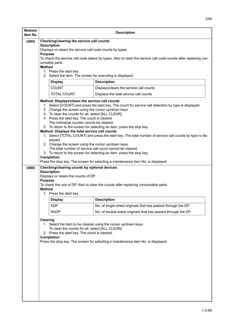
2JN
U904 Checking/clearing the service call countsDescriptionDisplays or clears the service call code counts by types.PurposeTo check the service call code status by types. Also to clear the service call code counts after replacing con-sumable parts.Method
1. Press the start key.2. Select the item. The screen for executing is displayed.
Method: Displays/clears the service call counts1. Select [COUNT] and press the start key. The count for service call detection by type is displayed.2. Change the screen using the cursor up/down keys.3. To clear the counts for all, select [ALL CLEAR].4. Press the start key. The count is cleared.
The individual counter cannot be cleared.5. To return to the screen for selecting an item, press the stop key.
Method: Displays the total service call counts1. Select [TOTAL COUNT] and press the start key. The total number of service call counts by type is dis-
played.2. Change the screen using the cursor up/down keys.
The total number of service call count cannot be cleared.3. To return to the screen for selecting an item, press the stop key.
CompletionPress the stop key. The screen for selecting a maintenance item No. is displayed.
U905 Checking/clearing counts by optional devicesDescriptionDisplays or clears the counts of DP.PurposeTo check the use of DP. Also to clear the counts after replacing consumable parts.Method
1. Press the start key.
Clearing1. Select the item to be cleared using the cursor up/down keys.
To clear the counts for all, select [ALL CLEAR].2. Press the start key. The count is cleared.
CompletionPress the stop key. The screen for selecting a maintenance item No. is displayed.
Maintenanceitem No. Description
Display Description
COUNT Displays/clears the service call counts
TOTAL COUNT Displays the total service call counts
Display Description
ADP No. of single-sided originals that has passed through the DP
RADP No. of double-sided originals that has passed through the DP
1-3-69
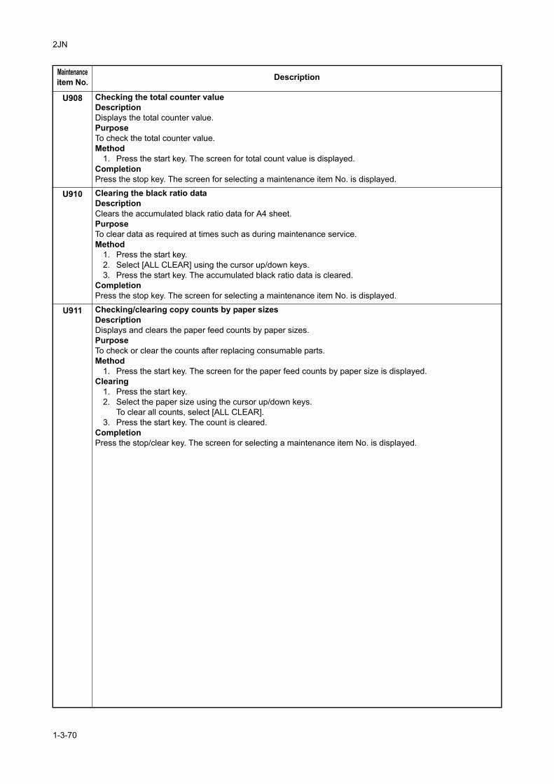
2JN
U908 Checking the total counter valueDescriptionDisplays the total counter value.PurposeTo check the total counter value.Method
1. Press the start key. The screen for total count value is displayed.CompletionPress the stop key. The screen for selecting a maintenance item No. is displayed.
U910 Clearing the black ratio dataDescriptionClears the accumulated black ratio data for A4 sheet.PurposeTo clear data as required at times such as during maintenance service.Method
1. Press the start key.2. Select [ALL CLEAR] using the cursor up/down keys.3. Press the start key. The accumulated black ratio data is cleared.
CompletionPress the stop key. The screen for selecting a maintenance item No. is displayed.
U911 Checking/clearing copy counts by paper sizesDescriptionDisplays and clears the paper feed counts by paper sizes.PurposeTo check or clear the counts after replacing consumable parts.Method
1. Press the start key. The screen for the paper feed counts by paper size is displayed.Clearing
1. Press the start key.2. Select the paper size using the cursor up/down keys.
To clear all counts, select [ALL CLEAR].3. Press the start key. The count is cleared.
CompletionPress the stop/clear key. The screen for selecting a maintenance item No. is displayed.
Maintenanceitem No. Description
1-3-70
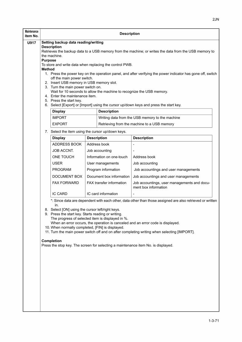
2JN
U917 Setting backup data reading/writingDescriptionRetrieves the backup data to a USB memory from the machine; or writes the data from the USB memory to the machine.PurposeTo store and write data when replacing the control PWB.Method
1. Press the power key on the operation panel, and after verifying the power indicator has gone off, switch off the main power switch.
2. Insert USB memory in USB memory slot.3. Turn the main power switch on.
Wait for 10 seconds to allow the machine to recognize the USB memory.4. Enter the maintenance item.5. Press the start key.6. Select [Export] or [Import] using the cursor up/down keys and press the start key.
7. Select the item using the cursor up/down keys.
*: Since data are dependent with each other, data other than those assigned are also retrieved or written in.
8. Select [ON] using the cursor left/right keys.9. Press the start key. Starts reading or writing.
The progress of selected item is displayed in %.When an error occurs, the operation is canceled and an error code is displayed.
10. When normally completed, [FIN] is displayed.11. Turn the main power switch off and on after completing writing when selecting [IMPORT].
CompletionPress the stop key. The screen for selecting a maintenance item No. is displayed.
Maintenanceitem No. Description
Display Description
IMPORT Writing data from the USB memory to the machine
EXPORT Retrieving from the machine to a USB memory
Display Description Description
ADDRESS BOOK Address book -
JOB ACCNT. Job accounting -
ONE TOUCH Information on one-touch Address book
USER User managements Job accounting
PROGRAM Program information Job accountings and user managements
DOCUMENT BOX Document box information Job accountings and user managements
FAX FORWARD FAX transfer information Job accountings, user managements and docu-ment box information
IC CARD IC card information -
1-3-71
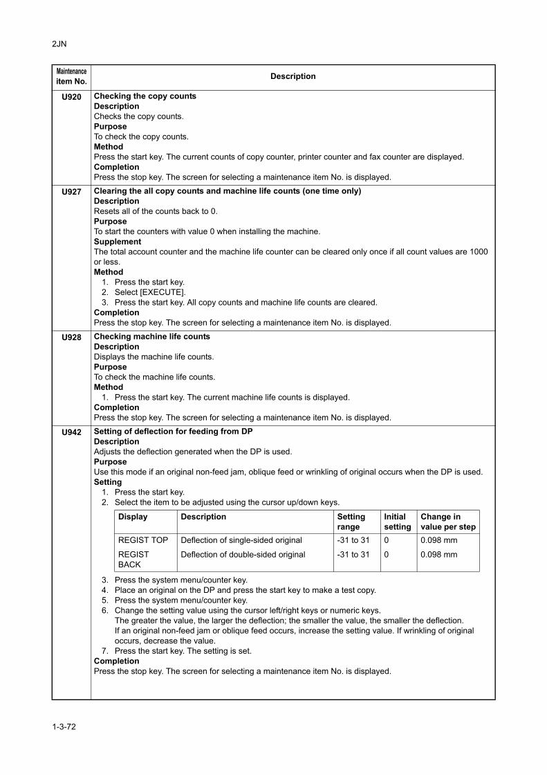
2JN
U920 Checking the copy countsDescriptionChecks the copy counts.PurposeTo check the copy counts.MethodPress the start key. The current counts of copy counter, printer counter and fax counter are displayed.CompletionPress the stop key. The screen for selecting a maintenance item No. is displayed.
U927 Clearing the all copy counts and machine life counts (one time only)DescriptionResets all of the counts back to 0.PurposeTo start the counters with value 0 when installing the machine.SupplementThe total account counter and the machine life counter can be cleared only once if all count values are 1000 or less.Method
1. Press the start key.2. Select [EXECUTE].3. Press the start key. All copy counts and machine life counts are cleared.
CompletionPress the stop key. The screen for selecting a maintenance item No. is displayed.
U928 Checking machine life countsDescriptionDisplays the machine life counts.PurposeTo check the machine life counts.Method
1. Press the start key. The current machine life counts is displayed.CompletionPress the stop key. The screen for selecting a maintenance item No. is displayed.
U942 Setting of deflection for feeding from DPDescriptionAdjusts the deflection generated when the DP is used.PurposeUse this mode if an original non-feed jam, oblique feed or wrinkling of original occurs when the DP is used.Setting
1. Press the start key.2. Select the item to be adjusted using the cursor up/down keys.
3. Press the system menu/counter key.4. Place an original on the DP and press the start key to make a test copy.5. Press the system menu/counter key.6. Change the setting value using the cursor left/right keys or numeric keys.
The greater the value, the larger the deflection; the smaller the value, the smaller the deflection.If an original non-feed jam or oblique feed occurs, increase the setting value. If wrinkling of original occurs, decrease the value.
7. Press the start key. The setting is set.CompletionPress the stop key. The screen for selecting a maintenance item No. is displayed.
Maintenanceitem No. Description
Display Description Settingrange
Initialsetting
Change invalue per step
REGIST TOP Deflection of single-sided original -31 to 31 0 0.098 mm
REGIST BACK
Deflection of double-sided original -31 to 31 0 0.098 mm
1-3-72
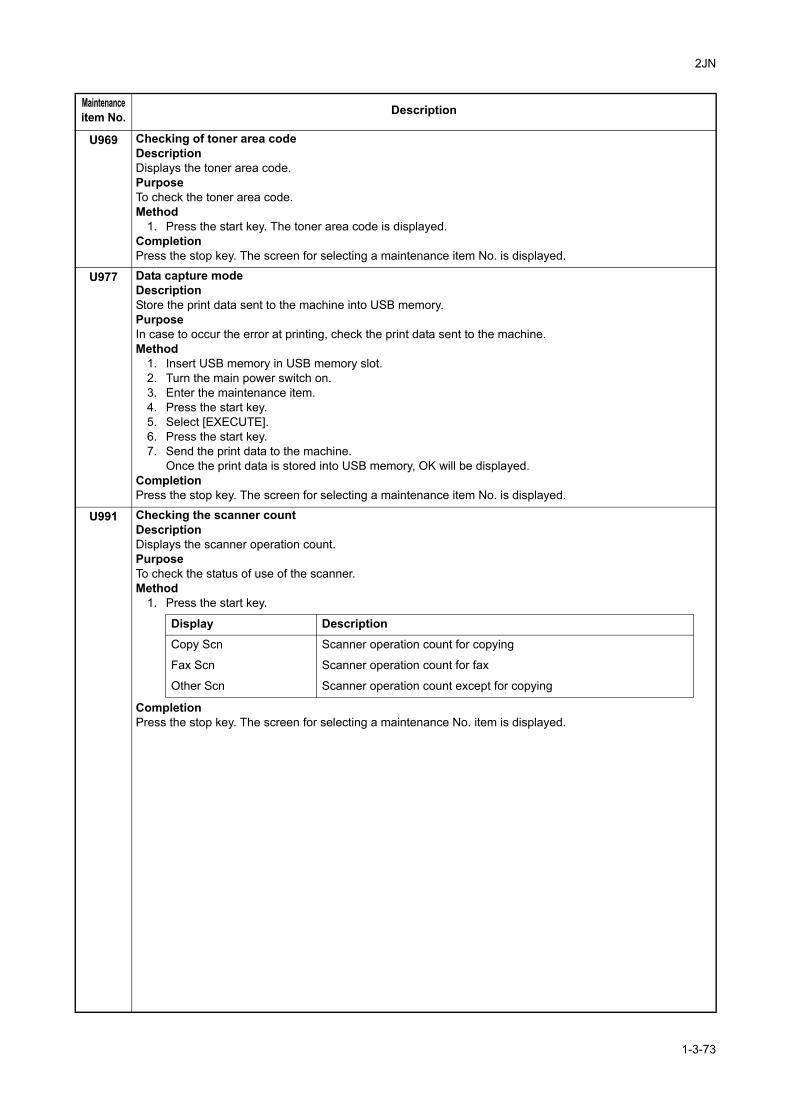
2JN
U969 Checking of toner area codeDescriptionDisplays the toner area code.PurposeTo check the toner area code.Method
1. Press the start key. The toner area code is displayed.CompletionPress the stop key. The screen for selecting a maintenance item No. is displayed.
U977 Data capture modeDescriptionStore the print data sent to the machine into USB memory.PurposeIn case to occur the error at printing, check the print data sent to the machine.Method
1. Insert USB memory in USB memory slot.2. Turn the main power switch on.3. Enter the maintenance item.4. Press the start key.5. Select [EXECUTE].6. Press the start key.7. Send the print data to the machine.
Once the print data is stored into USB memory, OK will be displayed.CompletionPress the stop key. The screen for selecting a maintenance item No. is displayed.
U991 Checking the scanner countDescriptionDisplays the scanner operation count.PurposeTo check the status of use of the scanner.Method
1. Press the start key.
CompletionPress the stop key. The screen for selecting a maintenance No. item is displayed.
Maintenanceitem No. Description
Display DescriptionCopy Scn Scanner operation count for copying
Fax Scn Scanner operation count for fax
Other Scn Scanner operation count except for copying
1-3-73
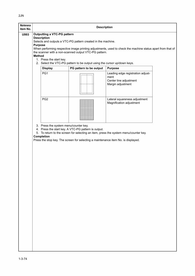
2JN
U993 Outputting a VTC-PG patternDescriptionSelects and outputs a VTC-PG pattern created in the machine.PurposeWhen performing respective image printing adjustments, used to check the machine status apart from that of the scanner with a non-scanned output VTC-PG pattern.Method
1. Press the start key.2. Select the VTC-PG pattern to be output using the cursor up/down keys.
3. Press the system menu/counter key.4. Press the start key. A VTC-PG pattern is output.5. To return to the screen for selecting an item, press the system menu/counter key.
CompletionPress the stop key. The screen for selecting a maintenance item No. is displayed.
Maintenanceitem No. Description
Display PG pattern to be output Purpose
PG1 Leading edge registration adjust-mentCenter line adjustmentMargin adjustment
PG2 Lateral squareness adjustmentMagnification adjustment
1-3-74
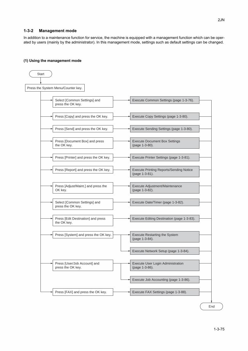
2JN
1-3-2 Management modeIn addition to a maintenance function for service, the machine is equipped with a management function which can be oper-ated by users (mainly by the administrator). In this management mode, settings such as default settings can be changed.
(1) Using the management mode
End
Press the System Menu/Counter key.
Select [Common Settings] and
press the OK key.
Select [Common Settings] and
press the OK key.
Execute Common Settings (page 1-3-76).
Press [Copy] and press the OK key. Execute Copy Settings (page 1-3-80).
Press [Send] and press the OK key. Execute Sending Settings (page 1-3-80).
Press [FAX] and press the OK key. Execute FAX Settings (page 1-3-88).
Press [Document Box] and press
the OK key.
Execute Document Box Settings
(page 1-3-80).
Press [Printer] and press the OK key. Execute Printer Settings (page 1-3-81).
Press [Report] and press the OK key. Execute Printing Reports/Sending Notice
(page 1-3-81).
Press [Adjust/Maint.] and press the
OK key.
Execute Adjustment/Maintenance
(page 1-3-82).
Execute Date/Timer (page 1-3-82).
Press [Edit Destination] and press
the OK key.
Execute Editing Destination (page 1-3-83).
Press [System] and press the OK key. Execute Restarting the System
(page 1-3-84).
Execute Network Setup (page 1-3-84).
Press [User/Job Account] and
press the OK key.
Execute User Login Administration
(page 1-3-86).
Execute Job Accounting (page 1-3-86).
Start
1-3-75
2JN
(2) Common Settings
Switching the Language for Display [Language]1. Select [Language] using the cursor up/down keys.2. Press the OK key.3. Select the language you want to use.4. Press the OK key.
Default Screen1. Select [Default Screen] using the cursor up/down
keys.2. Press the OK key.3. Select the screen to be displayed as the default
screen.4. Press the OK key.
Sound1. Select [Sound] using the cursor up/down keys.2. Press the OK key.3. Select [Buzzer] using the cursor up/down keys.4. Press the OK key.5. Select [Key Confirmation], [Job Finish], [Ready] or
[Warning] using the cursor up/down keys.6. Select [On] or [Off]7. Press the OK key.
Display Bright.1. Select [Display Bright.] using the cursor up/down
keys.2. Press the OK key.3. Select the display brightness.
[Darker -3] to [Lighter +3]4. Press the OK key.
Custom Original Size Setup1. Select [Orig./Paper Set.] using the cursor up/down
keys.2. Press the OK key.3. Select [Custom Orig.Size] using the cursor up/
down keys.4. Press the OK key.5. Enter the paper length (Y) using the numeric keys.6. Press the OK key.7. Enter the paper width (X) using the numeric keys.8. Press the OK key.
Default Original Size Setup1. Select [Orig./Paper Set.] using the cursor up/down
keys.2. Press the OK key.3. Select [Def. Orig. Size] using the cursor up/down
keys.4. Press the OK key.5. Select the paper size to be used as the default
value.6. Press the OK key.
Adding a Custom Size and Media Type for Paper to Print
1. Select [Orig./Paper Set.] using the cursor up/down keys.
2. Press the OK key.3. Select [Custom PaperSize] using the cursor up/
down keys.4. Press the OK key.5. Select the paper source and press the OK key.6. Enter the paper length (Y) using the numeric keys.7. Press the OK key.8. Enter the paper width (X) using the numeric keys.9. Press the OK key.10. Select the media type for which you want to set the
custom size.11. Press the OK key.
Paper Size and Media Type Setup for Cassettes1. Select [Orig./Paper Set.] using the cursor up/down
keys.2. Press the OK key.3. Select [Cassette 1 ( to 3) Set.] using the cursor up/
down keys.4. Press the OK key.5. Select [Cassette 1 ( to 3) Size] using the cursor up/
down keys.6. Select the paper size.7. Press the OK key.8. Select [Cassette 1 ( to 3) Type] using the cursor up/
down keys.9. Select the paper type.10. Press the OK key.
Paper Size and Media Type Setup for Multi Purpose Tray
1. Select [Orig./Paper Set.] using the cursor up/down keys.
2. Press the OK key.3. Select [MP Tray Set.] using the cursor up/down
keys.4. Press the OK key.5. Select [MP Tray Size] using the cursor up/down
keys.6. Select the paper size.
If you select [Others], you can select from addi-tional paper sizes.If you select [Size Entry], you can register a custom size.
7. Press the OK key.8. Select [MP Tray Type] and press the OK key.9. Select the paper type.10. Press the OK key.
1-3-76
2JN
Paper Weight1. Select [Orig./Paper Set.] using the cursor up/down
keys.2. Press the OK key.3. Select [MP Tray Set.] using the cursor up/down
keys.4. Press the OK key.5. Select the paper type and press the OK key.6. Select [Paper Weight] and press the OK key.7. Select the weight of paper.8. Press the OK key.9. Select [Print Density] and press the OK key.10. Select the print density.11. Press the OK key.
Default Paper Source1. Select [Orig./Paper Set.] using the cursor up/down
keys.2. Press the OK key.3. Select [Def. PaperSource] using the cursor up/
down keys.4. Press the OK key.5. Select the paper source to be used preferentially.6. Press the OK key.
Media for Auto Selection1. Select [Orig./Paper Set.] using the cursor up/down
keys.2. Press the OK key.3. Select [Media for Auto] using the cursor up/down
keys.4. Press the OK key.5. Select [All Media Type] or the paper type to be used
for paper selection.6. Press the OK key.
Special Paper Action1. Select [Orig./Paper Set.] using the cursor up/down
keys.2. Press the OK key.3. Select [SpcialPaper Act.] using the cursor up/down
keys.4. Press the OK key.5. Select [Adj. PrintDirect] or [Speed Priority].6. Press the OK key.
Preset Limit1. Select [Preset Limit] using the cursor up/down
keys.2. Press the OK key.3. Enter the number of copies.4. Press the OK key.
Switching Unit of Measurement1. Select [Measurement] using the cursor up/down
keys.2. Press the OK key.3. Select [inch] or [mm].4. Press the OK key.
Error Handling1. Select [Error Handling] using the cursor up/down
keys.2. Press the OK key.3. Select [DuplexPagerError] using the cursor up/
down keys.4. Press the OK key.5. Select the method to handle if duplex is disabled.6. Press the OK key.7. Select [PagerMismatchErr] using the cursor up/
down keys.8. Press the OK key.9. Select the method to handle paper mismatch.10. Press the OK key.
Orig.Orientation1. Select [Function Default] using the cursor up/down
keys.2. Press the OK key.3. Select [Orig.Orientation] using the cursor up/down
keys.4. Press the OK key.5. Select [Top Edge Top] or [Top Edge Left].6. Press the OK key.
Continuous Scan1. Select [Function Default] using the cursor up/down
keys.2. Press the OK key.3. Select [Continuous Scan] using the cursor up/down
keys.4. Press the OK key.5. Select [Off] or [On].6. Press the OK key.
Original Image1. Select [Function Default] using the cursor up/down
keys.2. Press the OK key.3. Select [Original Image] using the cursor up/down
keys.4. Press the OK key.5. Select [Text+Photo], [Photo], [Text] or [for OCR].6. Press the OK key.
1-3-77
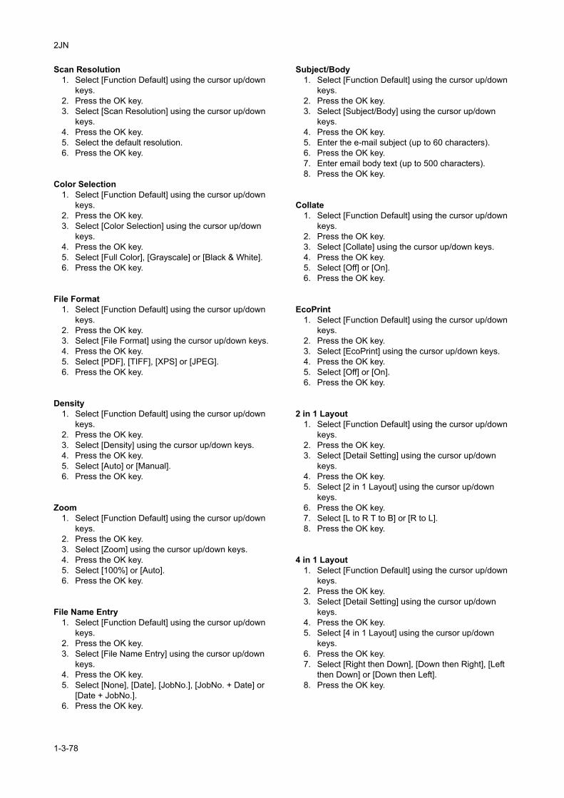
2JN
Scan Resolution1. Select [Function Default] using the cursor up/down
keys.2. Press the OK key.3. Select [Scan Resolution] using the cursor up/down
keys.4. Press the OK key.5. Select the default resolution.6. Press the OK key.
Color Selection1. Select [Function Default] using the cursor up/down
keys.2. Press the OK key.3. Select [Color Selection] using the cursor up/down
keys.4. Press the OK key.5. Select [Full Color], [Grayscale] or [Black & White].6. Press the OK key.
File Format1. Select [Function Default] using the cursor up/down
keys.2. Press the OK key.3. Select [File Format] using the cursor up/down keys.4. Press the OK key.5. Select [PDF], [TIFF], [XPS] or [JPEG].6. Press the OK key.
Density1. Select [Function Default] using the cursor up/down
keys.2. Press the OK key.3. Select [Density] using the cursor up/down keys.4. Press the OK key.5. Select [Auto] or [Manual].6. Press the OK key.
Zoom1. Select [Function Default] using the cursor up/down
keys.2. Press the OK key.3. Select [Zoom] using the cursor up/down keys.4. Press the OK key.5. Select [100%] or [Auto].6. Press the OK key.
File Name Entry1. Select [Function Default] using the cursor up/down
keys.2. Press the OK key.3. Select [File Name Entry] using the cursor up/down
keys.4. Press the OK key.5. Select [None], [Date], [JobNo.], [JobNo. + Date] or
[Date + JobNo.].6. Press the OK key.
Subject/Body1. Select [Function Default] using the cursor up/down
keys.2. Press the OK key.3. Select [Subject/Body] using the cursor up/down
keys.4. Press the OK key.5. Enter the e-mail subject (up to 60 characters).6. Press the OK key.7. Enter email body text (up to 500 characters).8. Press the OK key.
Collate1. Select [Function Default] using the cursor up/down
keys.2. Press the OK key.3. Select [Collate] using the cursor up/down keys.4. Press the OK key.5. Select [Off] or [On].6. Press the OK key.
EcoPrint1. Select [Function Default] using the cursor up/down
keys.2. Press the OK key.3. Select [EcoPrint] using the cursor up/down keys.4. Press the OK key.5. Select [Off] or [On].6. Press the OK key.
2 in 1 Layout1. Select [Function Default] using the cursor up/down
keys.2. Press the OK key.3. Select [Detail Setting] using the cursor up/down
keys.4. Press the OK key.5. Select [2 in 1 Layout] using the cursor up/down
keys.6. Press the OK key.7. Select [L to R T to B] or [R to L].8. Press the OK key.
4 in 1 Layout1. Select [Function Default] using the cursor up/down
keys.2. Press the OK key.3. Select [Detail Setting] using the cursor up/down
keys.4. Press the OK key.5. Select [4 in 1 Layout] using the cursor up/down
keys.6. Press the OK key.7. Select [Right then Down], [Down then Right], [Left
then Down] or [Down then Left].8. Press the OK key.
1-3-78
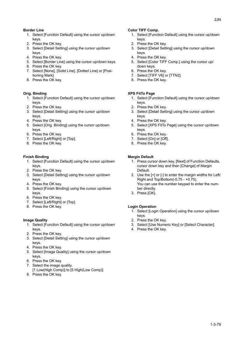
2JN
Border Line1. Select [Function Default] using the cursor up/down
keys.2. Press the OK key.3. Select [Detail Setting] using the cursor up/down
keys.4. Press the OK key.5. Select [Border Line] using the cursor up/down keys.6. Press the OK key.7. Select [None], [Solid Line], [Dotted Line] or [Posi-
tioning Mark].8. Press the OK key.
Orig. Binding1. Select [Function Default] using the cursor up/down
keys.2. Press the OK key.3. Select [Detail Setting] using the cursor up/down
keys.4. Press the OK key.5. Select [Orig. Binding] using the cursor up/down
keys.6. Press the OK key.7. Select [Left/Right] or [Top].8. Press the OK key.
Finish Binding1. Select [Function Default] using the cursor up/down
keys.2. Press the OK key.3. Select [Detail Setting] using the cursor up/down
keys.4. Press the OK key.5. Select [Finish Binding] using the cursor up/down
keys.6. Press the OK key.7. Select [Left/Right] or [Top].8. Press the OK key.
Image Quality1. Select [Function Default] using the cursor up/down
keys.2. Press the OK key.3. Select [Detail Setting] using the cursor up/down
keys.4. Press the OK key.5. Select [Image Quality] using the cursor up/down
keys.6. Press the OK key.7. Select the image quality.
[1 Low(High Comp)] to [5 High(Low Comp)]8. Press the OK key.
Color TIFF Comp.1. Select [Function Default] using the cursor up/down
keys.2. Press the OK key.3. Select [Detail Setting] using the cursor up/down
keys.4. Press the OK key.5. Select [Color TIFF Comp.] using the cursor up/
down keys.6. Press the OK key.7. Select [TIFF V6] or [TTN2].8. Press the OK key.
XPS FitTo Page1. Select [Function Default] using the cursor up/down
keys.2. Press the OK key.3. Select [Detail Setting] using the cursor up/down
keys.4. Press the OK key.5. Select [XPS FitTo Page] using the cursor up/down
keys.6. Press the OK key.7. Select [On] or [Off].8. Press the OK key.
Margin Default1. Press cursor down key, [Next] of Function Defaults,
cursor down key and then [Change] of Margin Default.
2. Use the [+] or [-] to enter the margin widths for Left/Right and Top/Bottom(-0.75 - +0.75).You can use the number keypad to enter the num-ber directly.
3. Press [OK].
Login Operation1. Select [Login Operation] using the cursor up/down
keys.2. Press the OK key.3. Select [Use Numeric Key] or [Select Character].4. Press the OK key.
1-3-79
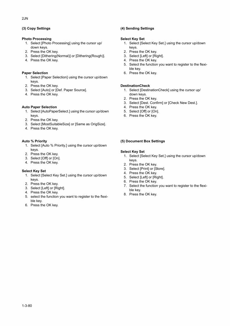
2JN
(3) Copy Settings
Photo Processing1. Select [Photo Processing] using the cursor up/
down keys.2. Press the OK key.3. Select [Dithering(Normal)] or [Dithering(Rough)].4. Press the OK key.
Paper Selection1. Select [Paper Selection] using the cursor up/down
keys.2. Press the OK key.3. Select [Auto] or [Def. Paper Source].4. Press the OK key.
Auto Paper Selection1. Select [AutoPaperSelect.] using the cursor up/down
keys.2. Press the OK key.3. Select [MostSuitableSize] or [Same as OrigSize].4. Press the OK key.
Auto % Priority1. Select [Auto % Priority.] using the cursor up/down
keys.2. Press the OK key.3. Select [Off] or [On].4. Press the OK key.
Select Key Set1. Select [Select Key Set.] using the cursor up/down
keys.2. Press the OK key.3. Select [Left] or [Right].4. Press the OK key.5. select the function you want to register to the flexi-
ble key.6. Press the OK key.
(4) Sending Settings
Select Key Set1. Select [Select Key Set.] using the cursor up/down
keys.2. Press the OK key.3. Select [Left] or [Right].4. Press the OK key.5. Select the function you want to register to the flexi-
ble key.6. Press the OK key.
DestinationCheck1. Select [DestinationCheck] using the cursor up/
down keys.2. Press the OK key.3. Select [Dest. Confirm] or [Check New Dest.].4. Press the OK key.5. Select [Off] or [On].6. Press the OK key.
(5) Document Box Settings
Select Key Set1. Select [Select Key Set.] using the cursor up/down
keys.2. Press the OK key.3. Select [Print] or [Store].4. Press the OK key.5. Select [Left] or [Right].6. Press the OK key.7. Select the function you want to register to the flexi-
ble key.8. Press the OK key.
1-3-80
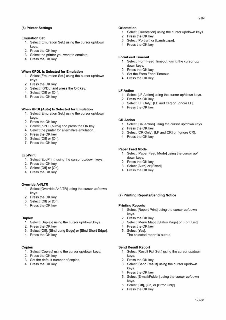
2JN
(6) Printer Settings
Emuration Set1. Select [Emuration Set.] using the cursor up/down
keys.2. Press the OK key.3. Select the printer you want to emulate.4. Press the OK key.
When KPDL Is Selected for Emulation1. Select [Emuration Set.] using the cursor up/down
keys.2. Press the OK key.3. Select [KPDL] and press the OK key.4. Select [Off] or [On].5. Press the OK key.
When KPDL(Auto) Is Selected for Emulation1. Select [Emuration Set.] using the cursor up/down
keys.2. Press the OK key.3. Select [KPDL(Auto)] and press the OK key.4. Select the printer for alternative emulation.5. Press the OK key.6. Select [Off] or [On].7. Press the OK key.
EcoPrint1. Select [EcoPrint] using the cursor up/down keys.2. Press the OK key.3. Select [Off] or [On].4. Press the OK key.
Override A4/LTR1. Select [Override A4/LTR] using the cursor up/down
keys.2. Press the OK key.3. Select [Off] or [On].4. Press the OK key.
Duplex1. Select [Duplex] using the cursor up/down keys.2. Press the OK key.3. Select [Off], [Bind Long Edge] or [Bind Short Edge].4. Press the OK key.
Copies1. Select [Copies] using the cursor up/down keys.2. Press the OK key.3. Set the default number of copies.4. Press the OK key.
Orientation1. Select [Orientation] using the cursor up/down keys.2. Press the OK key.3. Select [Portrait] or [Landscape].4. Press the OK key.
FormFeed Timeout1. Select [FormFeed Timeout] using the cursor up/
down keys.2. Press the OK key.3. Set the Form Feed Timeout.4. Press the OK key.
LF Action1. Select [LF Action] using the cursor up/down keys.2. Press the OK key.3. Select [LF Only], [LF and CR] or [Ignore LF].4. Press the OK key.
CR Action1. Select [CR Action] using the cursor up/down keys.2. Press the OK key.3. Select [CR Only], [LF and CR] or [Ignore CR].4. Press the OK key.
Paper Feed Mode1. Select [Paper Feed Mode] using the cursor up/
down keys.2. Press the OK key.3. Select [Auto] or [Fixed].4. Press the OK key.
(7) Printing Reports/Sending Notice
Printing Reports1. Select [Report Print] using the cursor up/down
keys.2. Press the OK key.3. Select [Menu Map], [Status Page] or [Font List].4. Press the OK key.5. Select [Yes].
The selected report is output.
Send Result Report1. Select [Result Rpt Set.] using the cursor up/down
keys.2. Press the OK key.3. Select [Send Result] using the cursor up/down
keys.4. Press the OK key.5. Select [E-mail/Folder] using the cursor up/down
keys.6. Select [Off], [On] or [Error Only].7. Press the OK key.
1-3-81
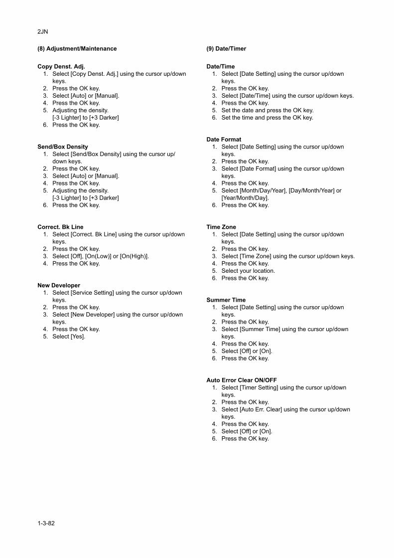
2JN
(8) Adjustment/Maintenance
Copy Denst. Adj.1. Select [Copy Denst. Adj.] using the cursor up/down
keys.2. Press the OK key.3. Select [Auto] or [Manual].4. Press the OK key.5. Adjusting the density.
[-3 Lighter] to [+3 Darker]6. Press the OK key.
Send/Box Density1. Select [Send/Box Density] using the cursor up/
down keys.2. Press the OK key.3. Select [Auto] or [Manual].4. Press the OK key.5. Adjusting the density.
[-3 Lighter] to [+3 Darker]6. Press the OK key.
Correct. Bk Line1. Select [Correct. Bk Line] using the cursor up/down
keys.2. Press the OK key.3. Select [Off], [On(Low)] or [On(High)].4. Press the OK key.
New Developer1. Select [Service Setting] using the cursor up/down
keys.2. Press the OK key.3. Select [New Developer] using the cursor up/down
keys.4. Press the OK key.5. Select [Yes].
(9) Date/Timer
Date/Time1. Select [Date Setting] using the cursor up/down
keys.2. Press the OK key.3. Select [Date/Time] using the cursor up/down keys.4. Press the OK key.5. Set the date and press the OK key.6. Set the time and press the OK key.
Date Format1. Select [Date Setting] using the cursor up/down
keys.2. Press the OK key.3. Select [Date Format] using the cursor up/down
keys.4. Press the OK key.5. Select [Month/Day/Year], [Day/Month/Year] or
[Year/Month/Day].6. Press the OK key.
Time Zone1. Select [Date Setting] using the cursor up/down
keys.2. Press the OK key.3. Select [Time Zone] using the cursor up/down keys.4. Press the OK key.5. Select your location.6. Press the OK key.
Summer Time1. Select [Date Setting] using the cursor up/down
keys.2. Press the OK key.3. Select [Summer Time] using the cursor up/down
keys.4. Press the OK key.5. Select [Off] or [On].6. Press the OK key.
Auto Error Clear ON/OFF1. Select [Timer Setting] using the cursor up/down
keys.2. Press the OK key.3. Select [Auto Err. Clear] using the cursor up/down
keys.4. Press the OK key.5. Select [Off] or [On].6. Press the OK key.
1-3-82
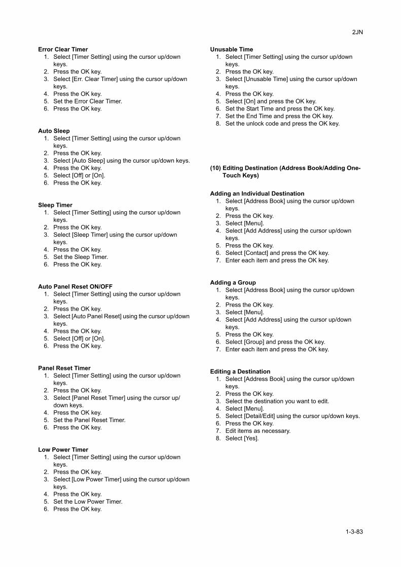
2JN
Error Clear Timer1. Select [Timer Setting] using the cursor up/down
keys.2. Press the OK key.3. Select [Err. Clear Timer] using the cursor up/down
keys.4. Press the OK key.5. Set the Error Clear Timer.6. Press the OK key.
Auto Sleep1. Select [Timer Setting] using the cursor up/down
keys.2. Press the OK key.3. Select [Auto Sleep] using the cursor up/down keys.4. Press the OK key.5. Select [Off] or [On].6. Press the OK key.
Sleep Timer1. Select [Timer Setting] using the cursor up/down
keys.2. Press the OK key.3. Select [Sleep Timer] using the cursor up/down
keys.4. Press the OK key.5. Set the Sleep Timer.6. Press the OK key.
Auto Panel Reset ON/OFF1. Select [Timer Setting] using the cursor up/down
keys.2. Press the OK key.3. Select [Auto Panel Reset] using the cursor up/down
keys.4. Press the OK key.5. Select [Off] or [On].6. Press the OK key.
Panel Reset Timer1. Select [Timer Setting] using the cursor up/down
keys.2. Press the OK key.3. Select [Panel Reset Timer] using the cursor up/
down keys.4. Press the OK key.5. Set the Panel Reset Timer.6. Press the OK key.
Low Power Timer1. Select [Timer Setting] using the cursor up/down
keys.2. Press the OK key.3. Select [Low Power Timer] using the cursor up/down
keys.4. Press the OK key.5. Set the Low Power Timer.6. Press the OK key.
Unusable Time1. Select [Timer Setting] using the cursor up/down
keys.2. Press the OK key.3. Select [Unusable Time] using the cursor up/down
keys.4. Press the OK key.5. Select [On] and press the OK key.6. Set the Start Time and press the OK key.7. Set the End Time and press the OK key.8. Set the unlock code and press the OK key.
(10) Editing Destination (Address Book/Adding One-Touch Keys)
Adding an Individual Destination1. Select [Address Book] using the cursor up/down
keys.2. Press the OK key.3. Select [Menu].4. Select [Add Address] using the cursor up/down
keys.5. Press the OK key.6. Select [Contact] and press the OK key.7. Enter each item and press the OK key.
Adding a Group1. Select [Address Book] using the cursor up/down
keys.2. Press the OK key.3. Select [Menu].4. Select [Add Address] using the cursor up/down
keys.5. Press the OK key.6. Select [Group] and press the OK key.7. Enter each item and press the OK key.
Editing a Destination1. Select [Address Book] using the cursor up/down
keys.2. Press the OK key.3. Select the destination you want to edit.4. Select [Menu].5. Select [Detail/Edit] using the cursor up/down keys.6. Press the OK key.7. Edit items as necessary.8. Select [Yes].
1-3-83

2JN
(11) Restarting the System
Restarting the System1. Select [Restart] using the cursor up/down keys.2. Press the OK key.3. Select [Yes].
The machine is restarted.
(12) Network Setup
LAN Interface Setup1. Select [Network Setting] using the cursor up/down
keys.2. Press the OK key.3. Select [LAN Interface] using the cursor up/down
keys.4. Press the OK key.5. Select the desired LAN interface.6. Press the OK key.
TCP/IP (IPv4) Setup1. Select [Network Setting] using the cursor up/down
keys.2. Press the OK key.3. Select [TCP/IP Settings] using the cursor up/down
keys.4. Press the OK key.5. Select [TCP/IP] using the cursor up/down keys.6. Press the OK key.7. Select [On] and press the OK key.8. Select [IPv4 Setting] using the cursor up/down
keys.9. Press the OK key.10. Select [DHCP] using the cursor up/down keys.11. Press the OK key.12. Select [Off] and press the OK key.13. Select [Bonjour] using the cursor up/down keys.14. Press the OK key.15. Select [Off] and press the OK key.16. Select [IP Address] using the cursor up/down keys.17. Press the OK key.18. Enter the IP address and press the OK key.19. Select [Subnet Mask] using the cursor up/down
keys.20. Press the OK key.21. Enter the Subnet Mask and press the OK key.22. Select [Default Gateway] using the cursor up/down
keys.23. Press the OK key.24. Enter the Default Gateway and press the OK key.
TCP/IP (IPv6) Setup1. Select [Network Setting] using the cursor up/down
keys.2. Press the OK key.3. Select [TCP/IP Settings] using the cursor up/down
keys.4. Press the OK key.5. Select [IPv6 Setting] using the cursor up/down
keys.6. Press the OK key.7. Select [On] or [Off].8. Press the OK key.
NetWare Setup1. Select [Network Setting] using the cursor up/down
keys.2. Press the OK key.3. Select [NetWare] using the cursor up/down keys.4. Press the OK key.5. Select [On] or [Off].6. Press the OK key.7. Select the desired frame type.8. Press the OK key.
AppleTalk Setup1. Select [Network Setting] using the cursor up/down
keys.2. Press the OK key.3. Select [AppleTalk] using the cursor up/down keys.4. Press the OK key.5. Select [On] or [Off].6. Press the OK key.
WSD Scan Setup1. Select [Network Setting] using the cursor up/down
keys.2. Press the OK key.3. Select [WSD-SCAN] using the cursor up/down
keys.4. Press the OK key.5. Select [On] or [Off].6. Press the OK key.
WSD Print Setup1. Select [Network Setting] using the cursor up/down
keys.2. Press the OK key.3. Select [WSD-PRINT] using the cursor up/down
keys.4. Press the OK key.5. Select [On] or [Off].6. Press the OK key.
1-3-84
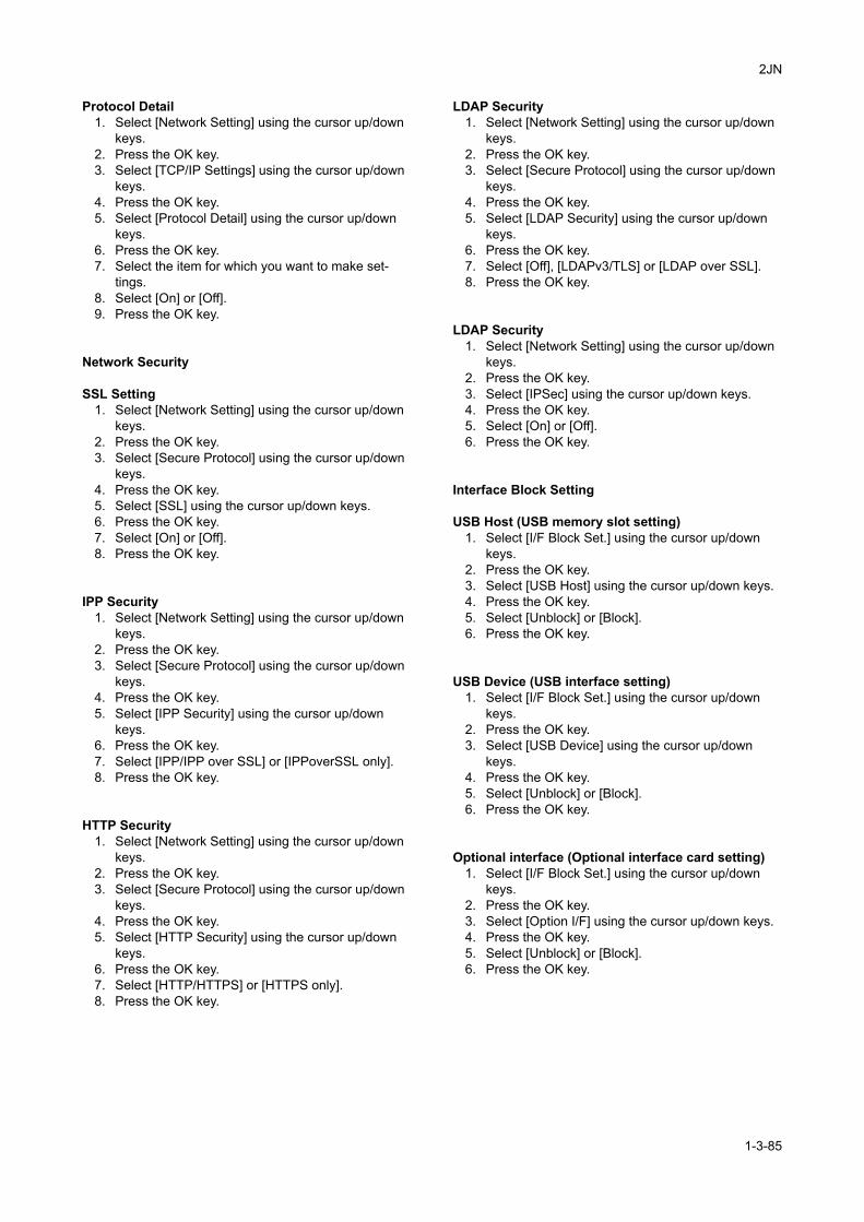
2JN
Protocol Detail1. Select [Network Setting] using the cursor up/down
keys.2. Press the OK key.3. Select [TCP/IP Settings] using the cursor up/down
keys.4. Press the OK key.5. Select [Protocol Detail] using the cursor up/down
keys.6. Press the OK key.7. Select the item for which you want to make set-
tings.8. Select [On] or [Off].9. Press the OK key.
Network Security
SSL Setting1. Select [Network Setting] using the cursor up/down
keys.2. Press the OK key.3. Select [Secure Protocol] using the cursor up/down
keys.4. Press the OK key.5. Select [SSL] using the cursor up/down keys.6. Press the OK key.7. Select [On] or [Off].8. Press the OK key.
IPP Security1. Select [Network Setting] using the cursor up/down
keys.2. Press the OK key.3. Select [Secure Protocol] using the cursor up/down
keys.4. Press the OK key.5. Select [IPP Security] using the cursor up/down
keys.6. Press the OK key.7. Select [IPP/IPP over SSL] or [IPPoverSSL only].8. Press the OK key.
HTTP Security1. Select [Network Setting] using the cursor up/down
keys.2. Press the OK key.3. Select [Secure Protocol] using the cursor up/down
keys.4. Press the OK key.5. Select [HTTP Security] using the cursor up/down
keys.6. Press the OK key.7. Select [HTTP/HTTPS] or [HTTPS only].8. Press the OK key.
LDAP Security1. Select [Network Setting] using the cursor up/down
keys.2. Press the OK key.3. Select [Secure Protocol] using the cursor up/down
keys.4. Press the OK key.5. Select [LDAP Security] using the cursor up/down
keys.6. Press the OK key.7. Select [Off], [LDAPv3/TLS] or [LDAP over SSL].8. Press the OK key.
LDAP Security1. Select [Network Setting] using the cursor up/down
keys.2. Press the OK key.3. Select [IPSec] using the cursor up/down keys.4. Press the OK key.5. Select [On] or [Off].6. Press the OK key.
Interface Block Setting
USB Host (USB memory slot setting)1. Select [I/F Block Set.] using the cursor up/down
keys.2. Press the OK key.3. Select [USB Host] using the cursor up/down keys.4. Press the OK key.5. Select [Unblock] or [Block].6. Press the OK key.
USB Device (USB interface setting)1. Select [I/F Block Set.] using the cursor up/down
keys.2. Press the OK key.3. Select [USB Device] using the cursor up/down
keys.4. Press the OK key.5. Select [Unblock] or [Block].6. Press the OK key.
Optional interface (Optional interface card setting)1. Select [I/F Block Set.] using the cursor up/down
keys.2. Press the OK key.3. Select [Option I/F] using the cursor up/down keys.4. Press the OK key.5. Select [Unblock] or [Block].6. Press the OK key.
1-3-85
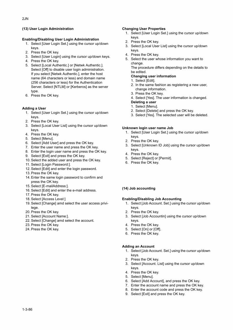
2JN
(13) User Login Administration
Enabling/Disabling User Login Administration1. Select [User Login Set.] using the cursor up/down
keys.2. Press the OK key.3. Select [User Login] using the cursor up/down keys.4. Press the OK key.5. Select [Local Authentic.] or [Netwk Authentic.].
Select [Off] to disable user login administration.If you select [Netwk Authentic.], enter the host name (64 characters or less) and domain name (256 characters or less) for the Authentication Server. Select [NTLM] or [Kerberos] as the server type.
6. Press the OK key.
Adding a User1. Select [User Login Set.] using the cursor up/down
keys.2. Press the OK key.3. Select [Local User List] using the cursor up/down
keys.4. Press the OK key.5. Select [Menu].6. Select [Add User] and press the OK key.7. Enter the user name and press the OK key.8. Enter the login user name and press the OK key.9. Select [Exit] and press the OK key.10. Select the added user and press the OK key.11. Select [Login Password:].12. Select [Edit] and enter the login password.13. Press the OK key.14. Enter the same login password to confirm and
press the OK key.15. Select [E-mailAddress:].16. Select [Edit] and enter the e-mail address.17. Press the OK key.18. Select [Access Level:]19. Select [Change] amd select the user access privi-
lege.20. Press the OK key.21. Select [Account Name:].22. Select [Change] amd select the account.23. Press the OK key.24. Press the OK key.
Changing User Properties1. Select [User Login Set.] using the cursor up/down
keys.2. Press the OK key.3. Select [Local User List] using the cursor up/down
keys.4. Press the OK key.5. Select the user whose information you want to
change.The procedure differs depending on the details to be edited.Changing user information1. Select [Edit].2. In the same fashion as registering a new user,
change information.3. Press the OK key.4. Select [Yes]. The user information is changed.Deleting a user1. Select [Menu].2. Select [Delete] and press the OK key.3. Select [Yes]. The selected user will be deleted.
Unknown login user name Job1. Select [User Login Set.] using the cursor up/down
keys.2. Press the OK key.3. Select [Unknown ID Job] using the cursor up/down
keys.4. Press the OK key.5. Select [Reject] or [Permit].6. Press the OK key.
(14) Job accounting
Enabling/Disabling Job Accounting1. Select [Job Account. Set.] using the cursor up/down
keys.2. Press the OK key.3. Select [Job Accountin] using the cursor up/down
keys.4. Press the OK key.5. Select [On] or [Off].6. Press the OK key.
Adding an Account1. Select [Job Account. Set.] using the cursor up/down
keys.2. Press the OK key.3. Select [Account. List] using the cursor up/down
keys.4. Press the OK key.5. Select [Menu].6. Select [Add Account], and press the OK key.7. Enter the account name and press the OK key.8. Enter the account code and press the OK key.9. Select [Exit] and press the OK key.
1-3-86
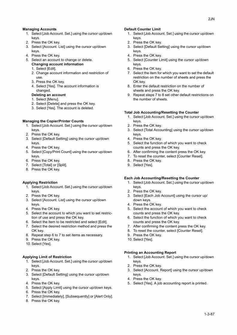
2JN
Managing Accounts1. Select [Job Account. Set.] using the cursor up/down
keys.2. Press the OK key.3. Select [Account. List] using the cursor up/down
keys.4. Press the OK key.5. Select an account to change or delete.
Changing account information1. Select [Edit].2. Change account information and restriction of
use.3. Press the OK key.4. Select [Yes]. The account information is
changed.Deleting an account1. Select [Menu].2. Select [Delete] and press the OK key.3. Select [Yes]. The account is deleted.
Managing the Copier/Printer Counts1. Select [Job Account. Set.] using the cursor up/down
keys.2. Press the OK key.3. Select [Default Setting] using the cursor up/down
keys.4. Press the OK key.5. Select [Copy/Print Count] using the cursor up/down
keys.6. Press the OK key.7. Select [Total] or [Split].8. Press the OK key.
Applying Restriction1. Select [Job Account. Set.] using the cursor up/down
keys.2. Press the OK key.3. Select [Account. List] using the cursor up/down
keys.4. Press the OK key.5. Select the account to which you want to set restric-
tion of use and press the OK key.6. Select the item to be restricted and select [Edit].7. Select the desired restriction method and press the
OK key.8. Repeat step 6 to 7 to set items as necessary.9. Press the OK key.10. Select [Yes].
Applying Limit of Restriction1. Select [Job Account. Set.] using the cursor up/down
keys.2. Press the OK key.3. Select [Default Setting] using the cursor up/down
keys.4. Press the OK key.5. Select [Apply Limit] using the cursor up/down keys.6. Press the OK key.7. Select [Immediately], [Subsequently] or [Alert Only].8. Press the OK key.
Default Counter Limit1. Select [Job Account. Set.] using the cursor up/down
keys.2. Press the OK key.3. Select [Default Setting] using the cursor up/down
keys.4. Press the OK key.5. Select [Counter Limit] using the cursor up/down
keys.6. Press the OK key.7. Select the item for which you want to set the default
restriction on the number of sheets and press the OK key.
8. Enter the default restriction on the number of sheets and press the OK key.
9. Repeat steps 7 to 8 set other default restrictions on the number of sheets.
Total Job Accounting/Resetting the Counter1. Select [Job Account. Set.] using the cursor up/down
keys.2. Press the OK key.3. Select [Total Accounting] using the cursor up/down
keys.4. Press the OK key.5. Select the function of which you want to check
counts and press the OK key.6. After confirming the content press the OK key.7. To reset the counter, select [Counter Reset].8. Press the OK key.9. Select [Yes].
Each Job Accounting/Resetting the Counter1. Select [Job Account. Set.] using the cursor up/down
keys.2. Press the OK key.3. Select [Each Job Account] using the cursor up/
down keys.4. Press the OK key.5. Select the account of which you want to check
counts and press the OK key.6. Select the function of which you want to check
counts and press the OK key.7. After confirming the content press the OK key.8. To reset the counter, select [Counter Reset].9. Press the OK key.10. Select [Yes].
Printing an Accounting Report1. Select [Job Account. Set.] using the cursor up/down
keys.2. Press the OK key.3. Select [Account. Report] using the cursor up/down
keys.4. Press the OK key.5. Select [Yes]. A job accounting report is printed.
1-3-87
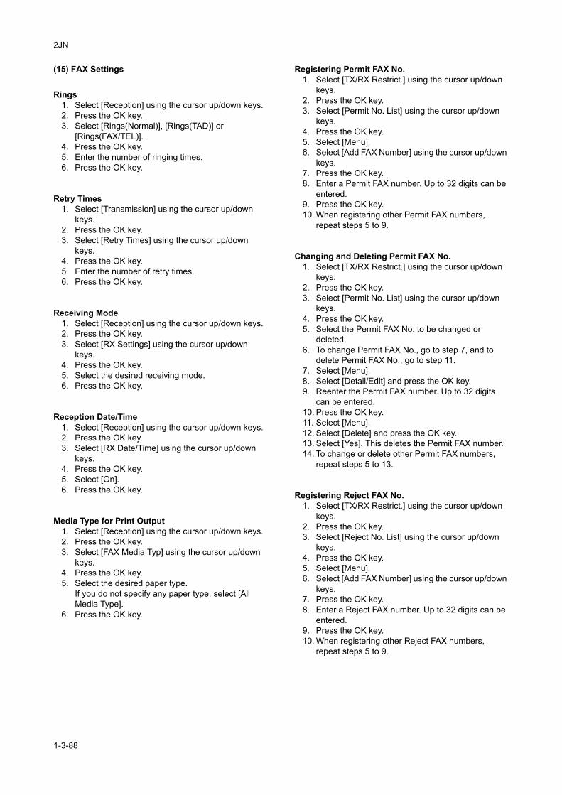
2JN
(15) FAX Settings
Rings1. Select [Reception] using the cursor up/down keys.2. Press the OK key.3. Select [Rings(Normal)], [Rings(TAD)] or
[Rings(FAX/TEL)].4. Press the OK key.5. Enter the number of ringing times.6. Press the OK key.
Retry Times1. Select [Transmission] using the cursor up/down
keys.2. Press the OK key.3. Select [Retry Times] using the cursor up/down
keys.4. Press the OK key.5. Enter the number of retry times.6. Press the OK key.
Receiving Mode1. Select [Reception] using the cursor up/down keys.2. Press the OK key.3. Select [RX Settings] using the cursor up/down
keys.4. Press the OK key.5. Select the desired receiving mode.6. Press the OK key.
Reception Date/Time1. Select [Reception] using the cursor up/down keys.2. Press the OK key.3. Select [RX Date/Time] using the cursor up/down
keys.4. Press the OK key.5. Select [On].6. Press the OK key.
Media Type for Print Output1. Select [Reception] using the cursor up/down keys.2. Press the OK key.3. Select [FAX Media Typ] using the cursor up/down
keys.4. Press the OK key.5. Select the desired paper type.
If you do not specify any paper type, select [All Media Type].
6. Press the OK key.
Registering Permit FAX No.1. Select [TX/RX Restrict.] using the cursor up/down
keys.2. Press the OK key.3. Select [Permit No. List] using the cursor up/down
keys.4. Press the OK key.5. Select [Menu].6. Select [Add FAX Number] using the cursor up/down
keys.7. Press the OK key.8. Enter a Permit FAX number. Up to 32 digits can be
entered.9. Press the OK key.10. When registering other Permit FAX numbers,
repeat steps 5 to 9.
Changing and Deleting Permit FAX No.1. Select [TX/RX Restrict.] using the cursor up/down
keys.2. Press the OK key.3. Select [Permit No. List] using the cursor up/down
keys.4. Press the OK key.5. Select the Permit FAX No. to be changed or
deleted.6. To change Permit FAX No., go to step 7, and to
delete Permit FAX No., go to step 11.7. Select [Menu].8. Select [Detail/Edit] and press the OK key.9. Reenter the Permit FAX number. Up to 32 digits
can be entered.10. Press the OK key.11. Select [Menu].12. Select [Delete] and press the OK key.13. Select [Yes]. This deletes the Permit FAX number.14. To change or delete other Permit FAX numbers,
repeat steps 5 to 13.
Registering Reject FAX No.1. Select [TX/RX Restrict.] using the cursor up/down
keys.2. Press the OK key.3. Select [Reject No. List] using the cursor up/down
keys.4. Press the OK key.5. Select [Menu].6. Select [Add FAX Number] using the cursor up/down
keys.7. Press the OK key.8. Enter a Reject FAX number. Up to 32 digits can be
entered.9. Press the OK key.10. When registering other Reject FAX numbers,
repeat steps 5 to 9.
1-3-88
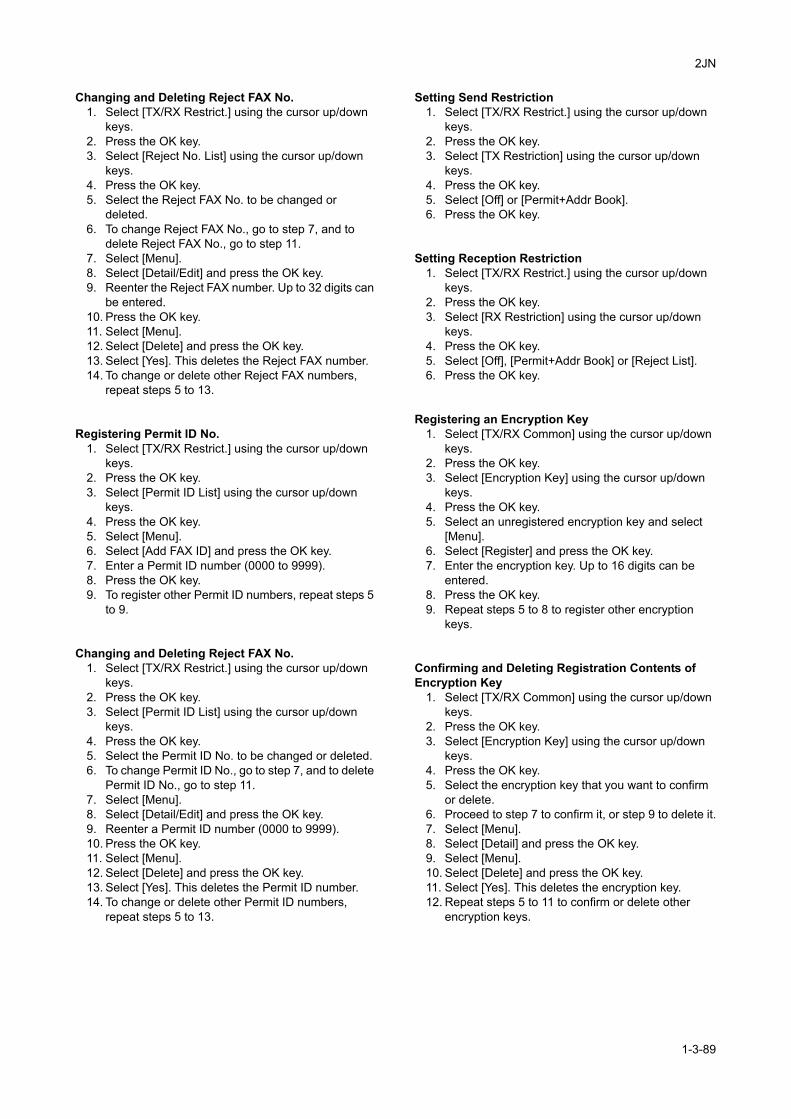
2JN
Changing and Deleting Reject FAX No.1. Select [TX/RX Restrict.] using the cursor up/down
keys.2. Press the OK key.3. Select [Reject No. List] using the cursor up/down
keys.4. Press the OK key.5. Select the Reject FAX No. to be changed or
deleted.6. To change Reject FAX No., go to step 7, and to
delete Reject FAX No., go to step 11.7. Select [Menu].8. Select [Detail/Edit] and press the OK key.9. Reenter the Reject FAX number. Up to 32 digits can
be entered.10. Press the OK key.11. Select [Menu].12. Select [Delete] and press the OK key.13. Select [Yes]. This deletes the Reject FAX number.14. To change or delete other Reject FAX numbers,
repeat steps 5 to 13.
Registering Permit ID No.1. Select [TX/RX Restrict.] using the cursor up/down
keys.2. Press the OK key.3. Select [Permit ID List] using the cursor up/down
keys.4. Press the OK key.5. Select [Menu].6. Select [Add FAX ID] and press the OK key.7. Enter a Permit ID number (0000 to 9999).8. Press the OK key.9. To register other Permit ID numbers, repeat steps 5
to 9.
Changing and Deleting Reject FAX No.1. Select [TX/RX Restrict.] using the cursor up/down
keys.2. Press the OK key.3. Select [Permit ID List] using the cursor up/down
keys.4. Press the OK key.5. Select the Permit ID No. to be changed or deleted.6. To change Permit ID No., go to step 7, and to delete
Permit ID No., go to step 11.7. Select [Menu].8. Select [Detail/Edit] and press the OK key.9. Reenter a Permit ID number (0000 to 9999).10. Press the OK key.11. Select [Menu].12. Select [Delete] and press the OK key.13. Select [Yes]. This deletes the Permit ID number.14. To change or delete other Permit ID numbers,
repeat steps 5 to 13.
Setting Send Restriction1. Select [TX/RX Restrict.] using the cursor up/down
keys.2. Press the OK key.3. Select [TX Restriction] using the cursor up/down
keys.4. Press the OK key.5. Select [Off] or [Permit+Addr Book].6. Press the OK key.
Setting Reception Restriction1. Select [TX/RX Restrict.] using the cursor up/down
keys.2. Press the OK key.3. Select [RX Restriction] using the cursor up/down
keys.4. Press the OK key.5. Select [Off], [Permit+Addr Book] or [Reject List].6. Press the OK key.
Registering an Encryption Key1. Select [TX/RX Common] using the cursor up/down
keys.2. Press the OK key.3. Select [Encryption Key] using the cursor up/down
keys.4. Press the OK key.5. Select an unregistered encryption key and select
[Menu].6. Select [Register] and press the OK key.7. Enter the encryption key. Up to 16 digits can be
entered.8. Press the OK key.9. Repeat steps 5 to 8 to register other encryption
keys.
Confirming and Deleting Registration Contents of Encryption Key
1. Select [TX/RX Common] using the cursor up/down keys.
2. Press the OK key.3. Select [Encryption Key] using the cursor up/down
keys.4. Press the OK key.5. Select the encryption key that you want to confirm
or delete.6. Proceed to step 7 to confirm it, or step 9 to delete it.7. Select [Menu].8. Select [Detail] and press the OK key.9. Select [Menu].10. Select [Delete] and press the OK key.11. Select [Yes]. This deletes the encryption key.12. Repeat steps 5 to 11 to confirm or delete other
encryption keys.
1-3-89
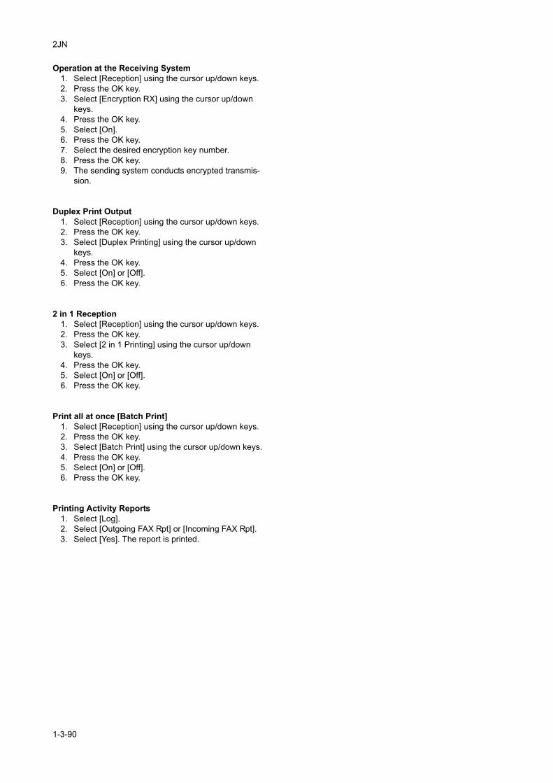
2JN
Operation at the Receiving System1. Select [Reception] using the cursor up/down keys.2. Press the OK key.3. Select [Encryption RX] using the cursor up/down
keys.4. Press the OK key.5. Select [On].6. Press the OK key.7. Select the desired encryption key number.8. Press the OK key.9. The sending system conducts encrypted transmis-
sion.
Duplex Print Output1. Select [Reception] using the cursor up/down keys.2. Press the OK key.3. Select [Duplex Printing] using the cursor up/down
keys.4. Press the OK key.5. Select [On] or [Off].6. Press the OK key.
2 in 1 Reception1. Select [Reception] using the cursor up/down keys.2. Press the OK key.3. Select [2 in 1 Printing] using the cursor up/down
keys.4. Press the OK key.5. Select [On] or [Off].6. Press the OK key.
Print all at once [Batch Print]1. Select [Reception] using the cursor up/down keys.2. Press the OK key.3. Select [Batch Print] using the cursor up/down keys.4. Press the OK key.5. Select [On] or [Off].6. Press the OK key.
Printing Activity Reports1. Select [Log].2. Select [Outgoing FAX Rpt] or [Incoming FAX Rpt].3. Select [Yes]. The report is printed.
1-3-90
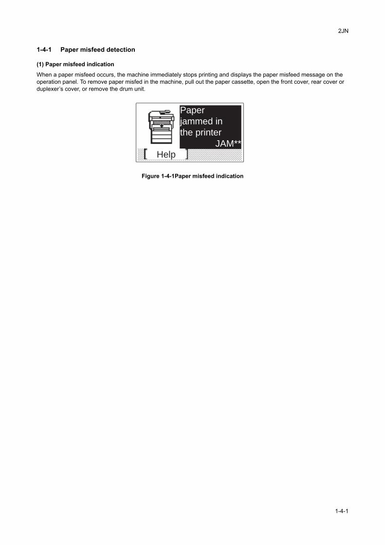
2JN
1-4 Troubleshooting
1-4-1 Paper misfeed detection
(1) Paper misfeed indication
When a paper misfeed occurs, the machine immediately stops printing and displays the paper misfeed message on the operation panel. To remove paper misfed in the machine, pull out the paper cassette, open the front cover, rear cover or duplexer’s cover, or remove the drum unit.
Figure 1-4-1Paper misfeed indication
Help
Paper
jammed in
the printer
JAM**
1-4-1
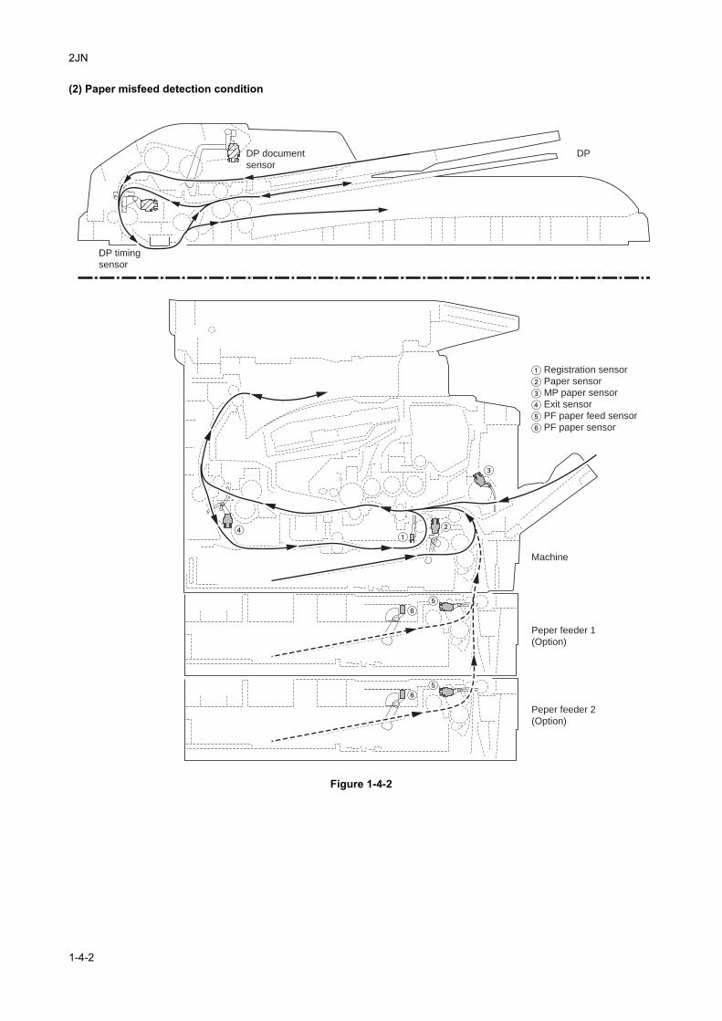
2JN
(2) Paper misfeed detection condition
Figure 1-4-2
Peper feeder 1
(Option)
Peper feeder 2
(Option)
Machine
DP
� Registration sensor
� Paper sensor
� MP paper sensor
� Exit sensor
� PF paper feed sensor
� PF paper sensor
�
�
��
��
��
DP timing
sensor
DP document
sensor
1-4-2
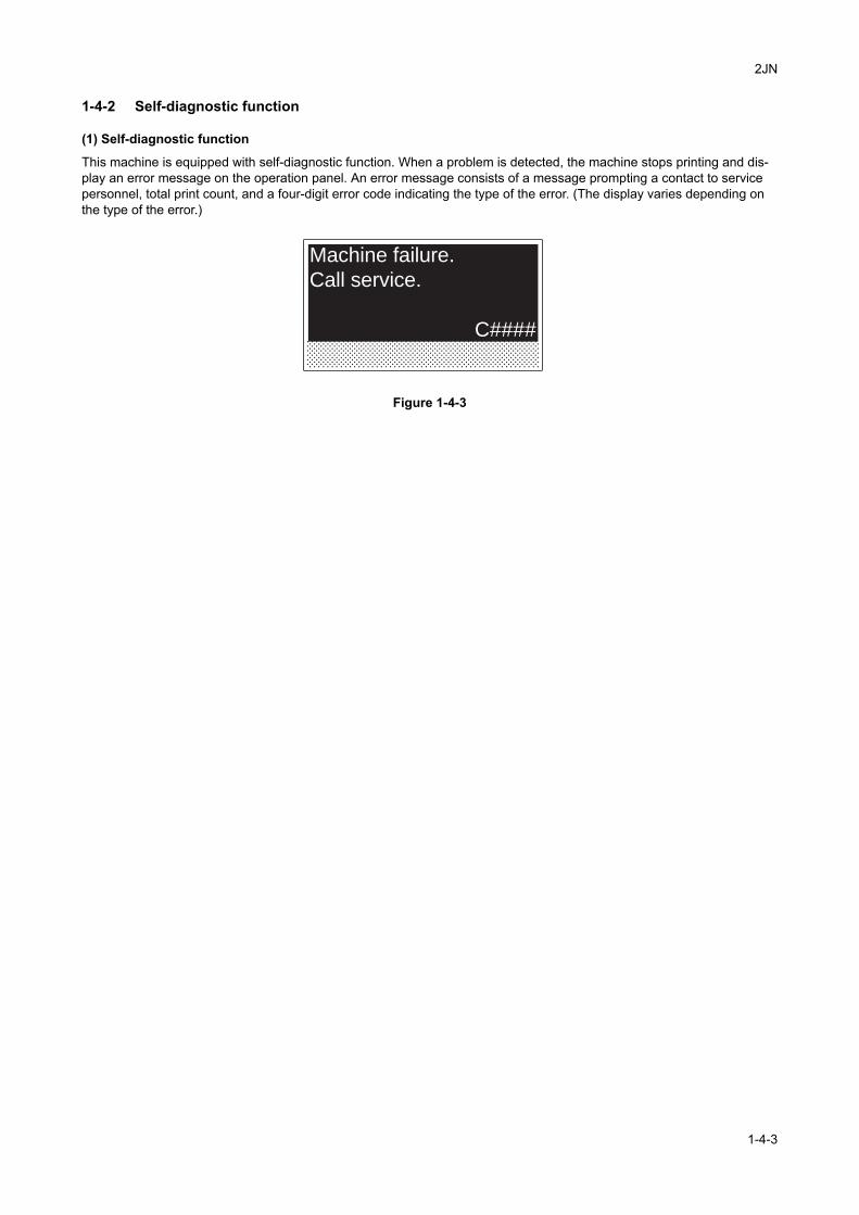
2JN
1-4-2 Self-diagnostic function
(1) Self-diagnostic function
This machine is equipped with self-diagnostic function. When a problem is detected, the machine stops printing and dis-play an error message on the operation panel. An error message consists of a message prompting a contact to service personnel, total print count, and a four-digit error code indicating the type of the error. (The display varies depending on the type of the error.)
Figure 1-4-3
Machine failure.
Call service.
C####
1-4-3
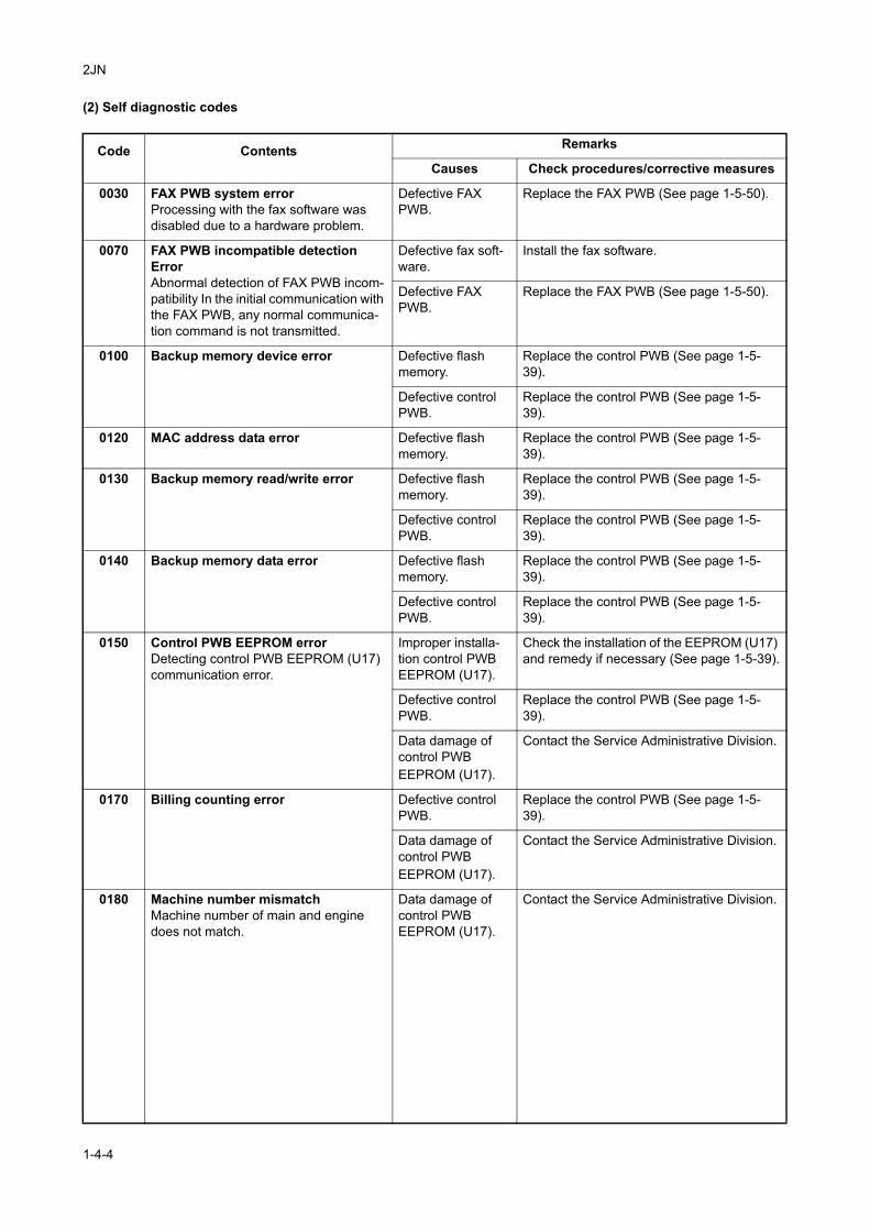
2JN
(2) Self diagnostic codes
Code Contents Remarks
Causes Check procedures/corrective measures
0030 FAX PWB system errorProcessing with the fax software was disabled due to a hardware problem.
Defective FAX PWB.
Replace the FAX PWB (See page 1-5-50).
0070 FAX PWB incompatible detection ErrorAbnormal detection of FAX PWB incom-patibility In the initial communication with the FAX PWB, any normal communica-tion command is not transmitted.
Defective fax soft-ware.
Install the fax software.
Defective FAX PWB.
Replace the FAX PWB (See page 1-5-50).
0100 Backup memory device error Defective flash memory.
Replace the control PWB (See page 1-5-39).
Defective control PWB.
Replace the control PWB (See page 1-5-39).
0120 MAC address data error Defective flash memory.
Replace the control PWB (See page 1-5-39).
0130 Backup memory read/write error Defective flash memory.
Replace the control PWB (See page 1-5-39).
Defective control PWB.
Replace the control PWB (See page 1-5-39).
0140 Backup memory data error Defective flash memory.
Replace the control PWB (See page 1-5-39).
Defective control PWB.
Replace the control PWB (See page 1-5-39).
0150 Control PWB EEPROM errorDetecting control PWB EEPROM (U17) communication error.
Improper installa-tion control PWB EEPROM (U17).
Check the installation of the EEPROM (U17) and remedy if necessary (See page 1-5-39).
Defective control PWB.
Replace the control PWB (See page 1-5-39).
Data damage of control PWB EEPROM (U17).
Contact the Service Administrative Division.
0170 Billing counting error Defective control PWB.
Replace the control PWB (See page 1-5-39).
Data damage of control PWB EEPROM (U17).
Contact the Service Administrative Division.
0180 Machine number mismatchMachine number of main and engine does not match.
Data damage of control PWB EEPROM (U17).
Contact the Service Administrative Division.
1-4-4
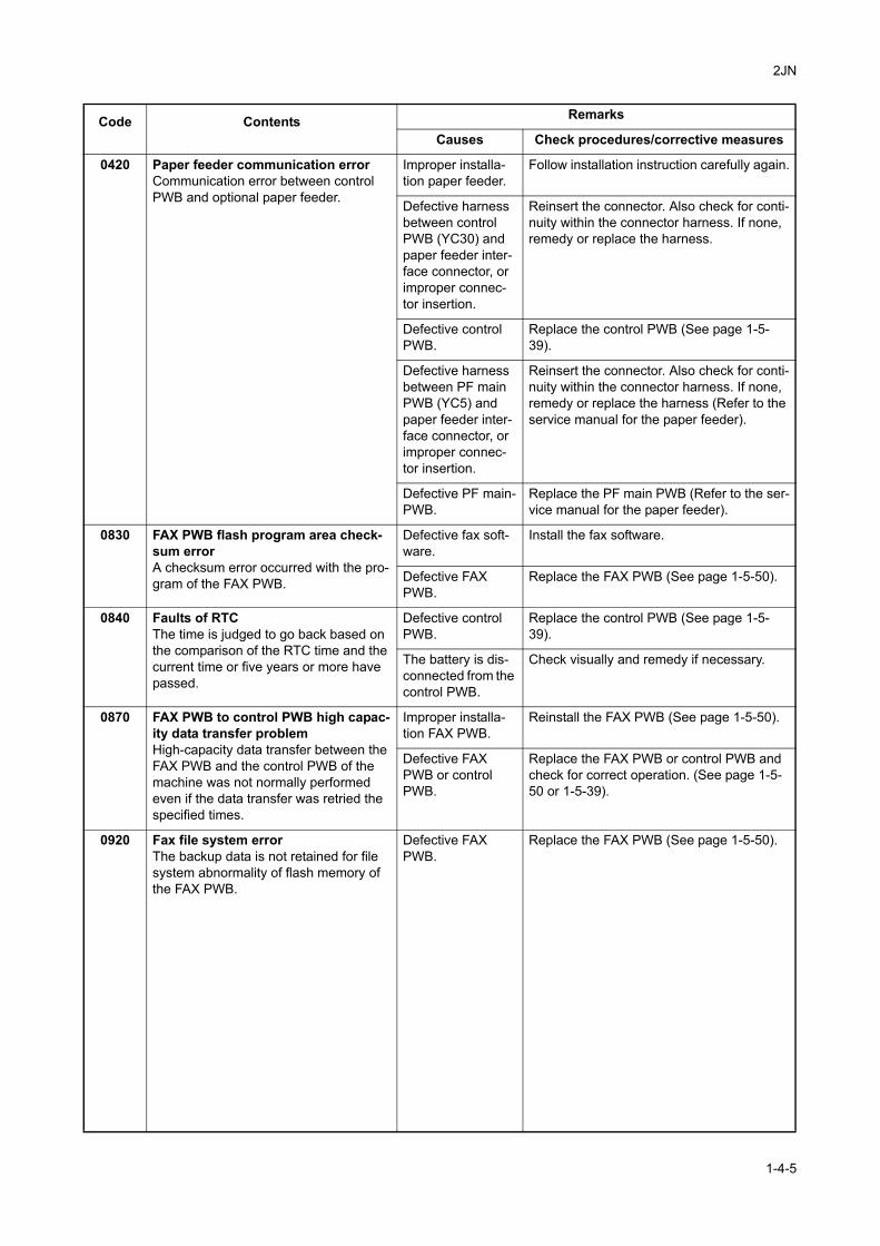
2JN
0420 Paper feeder communication errorCommunication error between control PWB and optional paper feeder.
Improper installa-tion paper feeder.
Follow installation instruction carefully again.
Defective harness between control PWB (YC30) and paper feeder inter-face connector, or improper connec-tor insertion.
Reinsert the connector. Also check for conti-nuity within the connector harness. If none, remedy or replace the harness.
Defective control PWB.
Replace the control PWB (See page 1-5-39).
Defective harness between PF main PWB (YC5) and paper feeder inter-face connector, or improper connec-tor insertion.
Reinsert the connector. Also check for conti-nuity within the connector harness. If none, remedy or replace the harness (Refer to the service manual for the paper feeder).
Defective PF main-PWB.
Replace the PF main PWB (Refer to the ser-vice manual for the paper feeder).
0830 FAX PWB flash program area check-sum errorA checksum error occurred with the pro-gram of the FAX PWB.
Defective fax soft-ware.
Install the fax software.
Defective FAX PWB.
Replace the FAX PWB (See page 1-5-50).
0840 Faults of RTCThe time is judged to go back based on the comparison of the RTC time and the current time or five years or more have passed.
Defective control PWB.
Replace the control PWB (See page 1-5-39).
The battery is dis-connected from the control PWB.
Check visually and remedy if necessary.
0870 FAX PWB to control PWB high capac-ity data transfer problemHigh-capacity data transfer between the FAX PWB and the control PWB of the machine was not normally performed even if the data transfer was retried the specified times.
Improper installa-tion FAX PWB.
Reinstall the FAX PWB (See page 1-5-50).
Defective FAX PWB or control PWB.
Replace the FAX PWB or control PWB and check for correct operation. (See page 1-5-50 or 1-5-39).
0920 Fax file system errorThe backup data is not retained for file system abnormality of flash memory of the FAX PWB.
Defective FAX PWB.
Replace the FAX PWB (See page 1-5-50).
Code Contents Remarks
Causes Check procedures/corrective measures
1-4-5
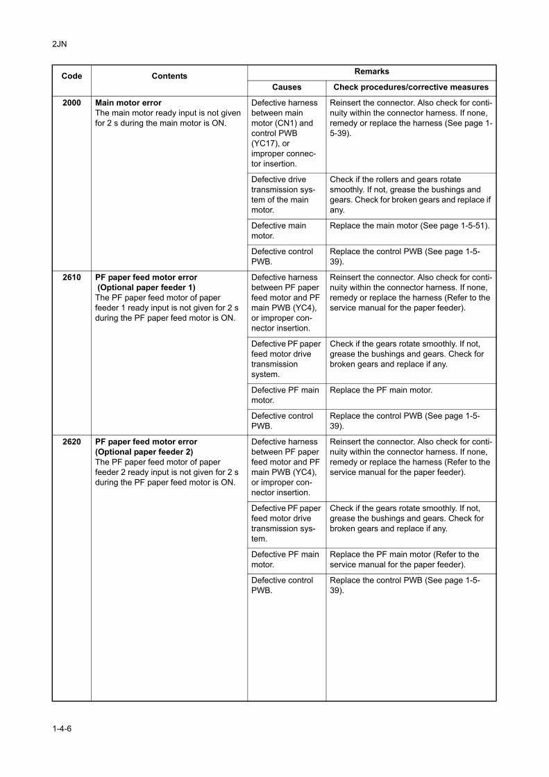
2JN
2000 Main motor errorThe main motor ready input is not given for 2 s during the main motor is ON.
Defective harness between main motor (CN1) and control PWB (YC17), or improper connec-tor insertion.
Reinsert the connector. Also check for conti-nuity within the connector harness. If none, remedy or replace the harness (See page 1-5-39).
Defective drive transmission sys-tem of the main motor.
Check if the rollers and gears rotate smoothly. If not, grease the bushings and gears. Check for broken gears and replace if any.
Defective main motor.
Replace the main motor (See page 1-5-51).
Defective control PWB.
Replace the control PWB (See page 1-5-39).
2610 PF paper feed motor error (Optional paper feeder 1)The PF paper feed motor of paper feeder 1 ready input is not given for 2 s during the PF paper feed motor is ON.
Defective harness between PF paper feed motor and PF main PWB (YC4), or improper con-nector insertion.
Reinsert the connector. Also check for conti-nuity within the connector harness. If none, remedy or replace the harness (Refer to the service manual for the paper feeder).
Defective PF paper feed motor drive transmission system.
Check if the gears rotate smoothly. If not, grease the bushings and gears. Check for broken gears and replace if any.
Defective PF main motor.
Replace the PF main motor.
Defective control PWB.
Replace the control PWB (See page 1-5-39).
2620 PF paper feed motor error(Optional paper feeder 2)The PF paper feed motor of paper feeder 2 ready input is not given for 2 s during the PF paper feed motor is ON.
Defective harness between PF paper feed motor and PF main PWB (YC4), or improper con-nector insertion.
Reinsert the connector. Also check for conti-nuity within the connector harness. If none, remedy or replace the harness (Refer to the service manual for the paper feeder).
Defective PF paper feed motor drive transmission sys-tem.
Check if the gears rotate smoothly. If not, grease the bushings and gears. Check for broken gears and replace if any.
Defective PF main motor.
Replace the PF main motor (Refer to the service manual for the paper feeder).
Defective control PWB.
Replace the control PWB (See page 1-5-39).
Code Contents Remarks
Causes Check procedures/corrective measures
1-4-6
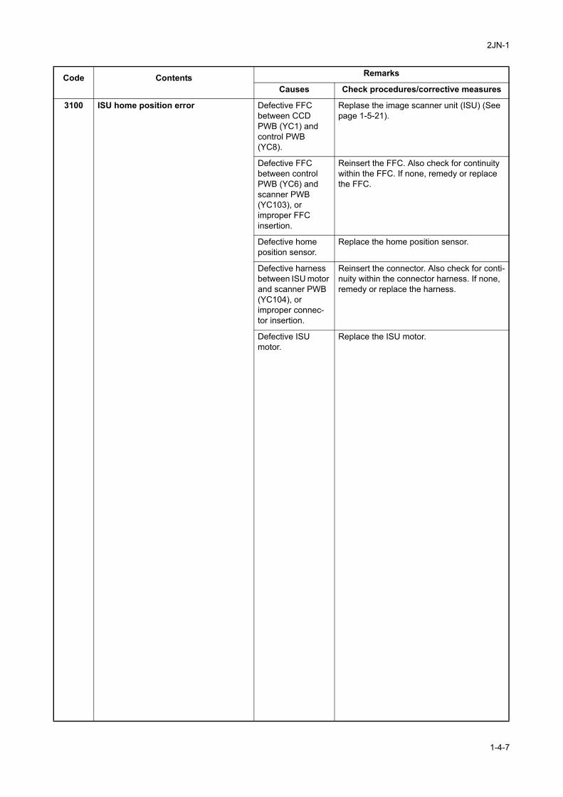
2JN-1
3100 ISU home position error Defective FFC between CCD PWB (YC1) and control PWB (YC8).
Replase the image scanner unit (ISU) (See page 1-5-21).
Defective FFC between control PWB (YC6) and scanner PWB (YC103), or improper FFC insertion.
Reinsert the FFC. Also check for continuity within the FFC. If none, remedy or replace the FFC.
Defective home position sensor.
Replace the home position sensor.
Defective harness between ISU motor and scanner PWB (YC104), or improper connec-tor insertion.
Reinsert the connector. Also check for conti-nuity within the connector harness. If none, remedy or replace the harness.
Defective ISU motor.
Replace the ISU motor.
Code Contents Remarks
Causes Check procedures/corrective measures
1-4-7
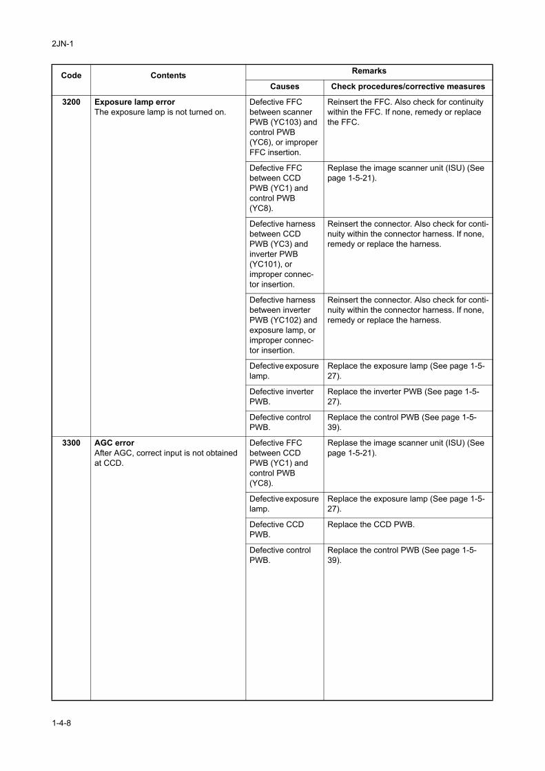
2JN-1
3200 Exposure lamp errorThe exposure lamp is not turned on.
Defective FFC between scanner PWB (YC103) and control PWB (YC6), or improper FFC insertion.
Reinsert the FFC. Also check for continuity within the FFC. If none, remedy or replace the FFC.
Defective FFC between CCD PWB (YC1) and control PWB (YC8).
Replase the image scanner unit (ISU) (See page 1-5-21).
Defective harness between CCD PWB (YC3) and inverter PWB (YC101), or improper connec-tor insertion.
Reinsert the connector. Also check for conti-nuity within the connector harness. If none, remedy or replace the harness.
Defective harness between inverter PWB (YC102) and exposure lamp, or improper connec-tor insertion.
Reinsert the connector. Also check for conti-nuity within the connector harness. If none, remedy or replace the harness.
Defective exposure lamp.
Replace the exposure lamp (See page 1-5-27).
Defective inverter PWB.
Replace the inverter PWB (See page 1-5-27).
Defective control PWB.
Replace the control PWB (See page 1-5-39).
3300 AGC errorAfter AGC, correct input is not obtained at CCD.
Defective FFC between CCD PWB (YC1) and control PWB (YC8).
Replase the image scanner unit (ISU) (See page 1-5-21).
Defective exposure lamp.
Replace the exposure lamp (See page 1-5-27).
Defective CCD PWB.
Replace the CCD PWB.
Defective control PWB.
Replace the control PWB (See page 1-5-39).
Code Contents Remarks
Causes Check procedures/corrective measures
1-4-8
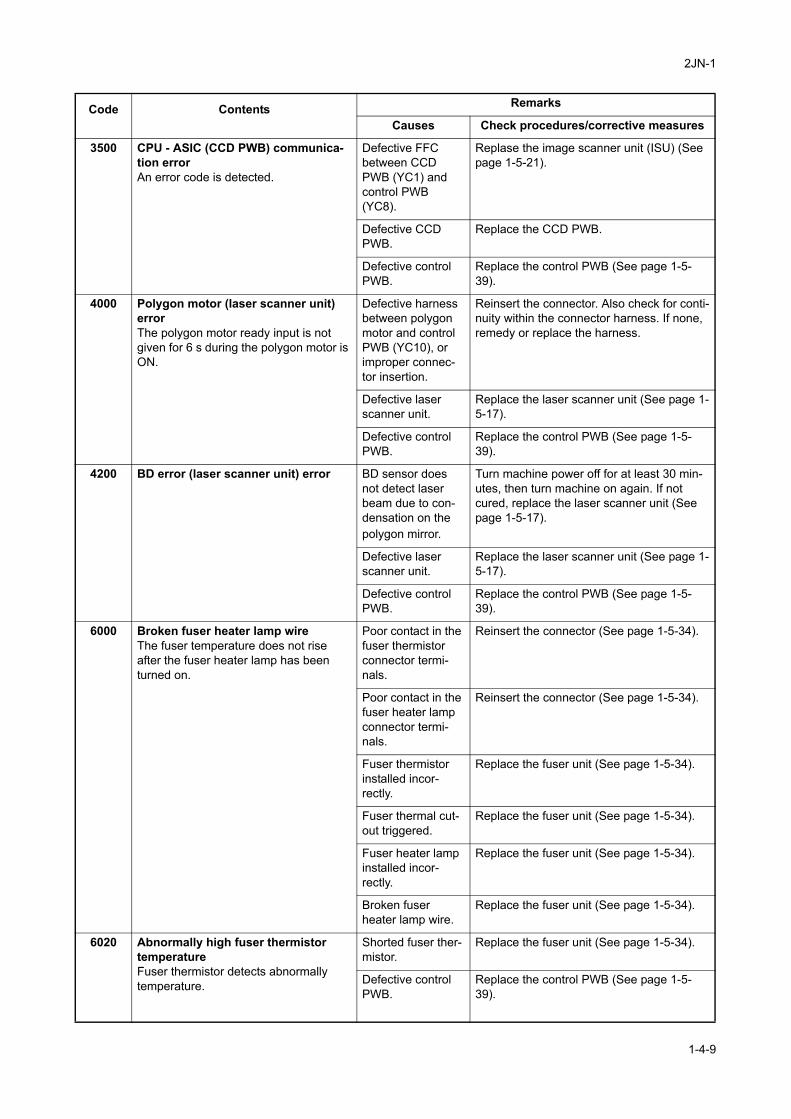
2JN-1
3500 CPU - ASIC (CCD PWB) communica-tion errorAn error code is detected.
Defective FFC between CCD PWB (YC1) and control PWB (YC8).
Replase the image scanner unit (ISU) (See page 1-5-21).
Defective CCD PWB.
Replace the CCD PWB.
Defective control PWB.
Replace the control PWB (See page 1-5-39).
4000 Polygon motor (laser scanner unit) errorThe polygon motor ready input is not given for 6 s during the polygon motor is ON.
Defective harness between polygon motor and control PWB (YC10), or improper connec-tor insertion.
Reinsert the connector. Also check for conti-nuity within the connector harness. If none, remedy or replace the harness.
Defective laser scanner unit.
Replace the laser scanner unit (See page 1-5-17).
Defective control PWB.
Replace the control PWB (See page 1-5-39).
4200 BD error (laser scanner unit) error BD sensor does not detect laser beam due to con-densation on the polygon mirror.
Turn machine power off for at least 30 min-utes, then turn machine on again. If not cured, replace the laser scanner unit (See page 1-5-17).
Defective laser scanner unit.
Replace the laser scanner unit (See page 1-5-17).
Defective control PWB.
Replace the control PWB (See page 1-5-39).
6000 Broken fuser heater lamp wireThe fuser temperature does not rise after the fuser heater lamp has been turned on.
Poor contact in the fuser thermistor connector termi-nals.
Reinsert the connector (See page 1-5-34).
Poor contact in the fuser heater lamp connector termi-nals.
Reinsert the connector (See page 1-5-34).
Fuser thermistor installed incor-rectly.
Replace the fuser unit (See page 1-5-34).
Fuser thermal cut-out triggered.
Replace the fuser unit (See page 1-5-34).
Fuser heater lamp installed incor-rectly.
Replace the fuser unit (See page 1-5-34).
Broken fuser heater lamp wire.
Replace the fuser unit (See page 1-5-34).
6020 Abnormally high fuser thermistor temperatureFuser thermistor detects abnormally temperature.
Shorted fuser ther-mistor.
Replace the fuser unit (See page 1-5-34).
Defective control PWB.
Replace the control PWB (See page 1-5-39).
Code Contents Remarks
Causes Check procedures/corrective measures
1-4-9
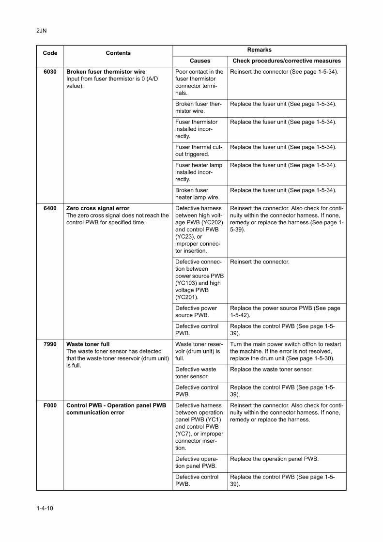
2JN
6030 Broken fuser thermistor wireInput from fuser thermistor is 0 (A/D value).
Poor contact in the fuser thermistor connector termi-nals.
Reinsert the connector (See page 1-5-34).
Broken fuser ther-mistor wire.
Replace the fuser unit (See page 1-5-34).
Fuser thermistor installed incor-rectly.
Replace the fuser unit (See page 1-5-34).
Fuser thermal cut-out triggered.
Replace the fuser unit (See page 1-5-34).
Fuser heater lamp installed incor-rectly.
Replace the fuser unit (See page 1-5-34).
Broken fuser heater lamp wire.
Replace the fuser unit (See page 1-5-34).
6400 Zero cross signal errorThe zero cross signal does not reach the control PWB for specified time.
Defective harness between high volt-age PWB (YC202) and control PWB (YC23), or improper connec-tor insertion.
Reinsert the connector. Also check for conti-nuity within the connector harness. If none, remedy or replace the harness (See page 1-5-39).
Defective connec-tion between power source PWB (YC103) and high voltage PWB (YC201).
Reinsert the connector.
Defective power source PWB.
Replace the power source PWB (See page 1-5-42).
Defective control PWB.
Replace the control PWB (See page 1-5-39).
7990 Waste toner fullThe waste toner sensor has detected that the waste toner reservoir (drum unit) is full.
Waste toner reser-voir (drum unit) is full.
Turn the main power switch off/on to restart the machine. If the error is not resolved, replace the drum unit (See page 1-5-30).
Defective waste toner sensor.
Replace the waste toner sensor.
Defective control PWB.
Replace the control PWB (See page 1-5-39).
F000 Control PWB - Operation panel PWB communication error
Defective harness between operation panel PWB (YC1) and control PWB (YC7), or improper connector inser-tion.
Reinsert the connector. Also check for conti-nuity within the connector harness. If none, remedy or replace the harness.
Defective opera-tion panel PWB.
Replace the operation panel PWB.
Defective control PWB.
Replace the control PWB (See page 1-5-39).
Code Contents Remarks
Causes Check procedures/corrective measures
1-4-10
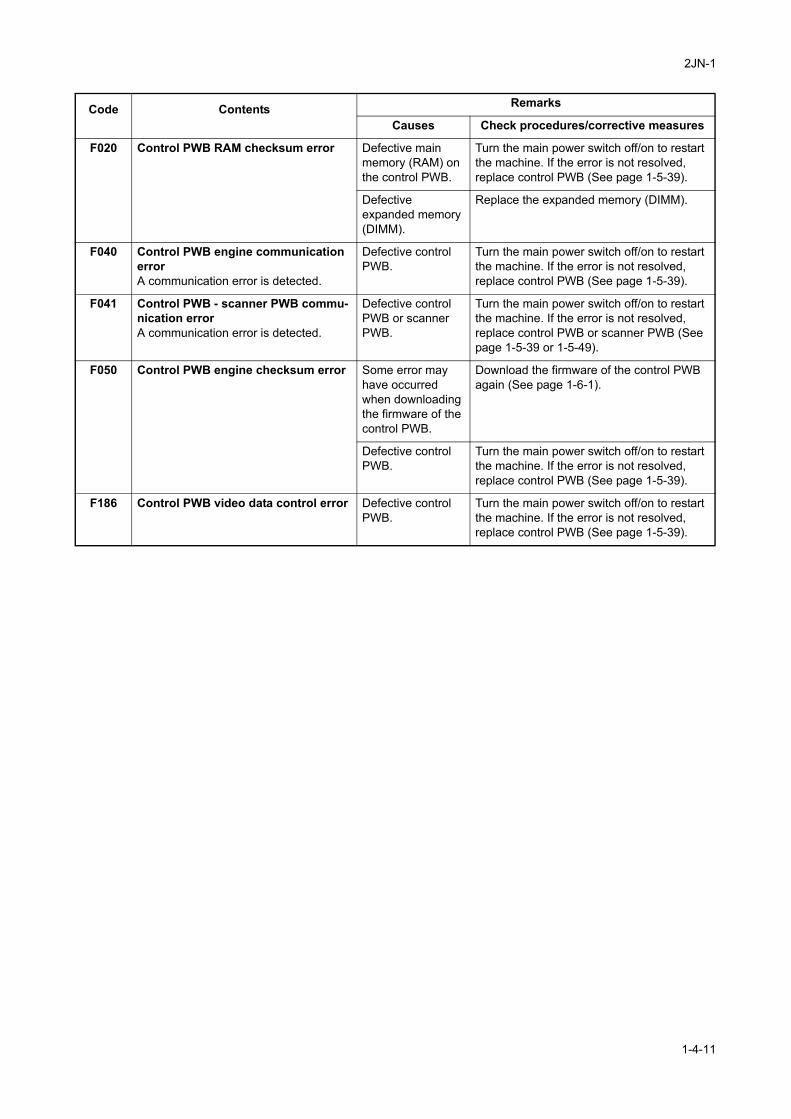
2JN-1
F020 Control PWB RAM checksum error Defective main memory (RAM) on the control PWB.
Turn the main power switch off/on to restart the machine. If the error is not resolved, replace control PWB (See page 1-5-39).
Defective expanded memory (DIMM).
Replace the expanded memory (DIMM).
F040 Control PWB engine communication errorA communication error is detected.
Defective control PWB.
Turn the main power switch off/on to restart the machine. If the error is not resolved, replace control PWB (See page 1-5-39).
F041 Control PWB - scanner PWB commu-nication errorA communication error is detected.
Defective control PWB or scanner PWB.
Turn the main power switch off/on to restart the machine. If the error is not resolved, replace control PWB or scanner PWB (See page 1-5-39 or 1-5-49).
F050 Control PWB engine checksum error Some error may have occurred when downloading the firmware of the control PWB.
Download the firmware of the control PWB again (See page 1-6-1).
Defective control PWB.
Turn the main power switch off/on to restart the machine. If the error is not resolved, replace control PWB (See page 1-5-39).
F186 Control PWB video data control error Defective control PWB.
Turn the main power switch off/on to restart the machine. If the error is not resolved, replace control PWB (See page 1-5-39).
Code Contents Remarks
Causes Check procedures/corrective measures
1-4-11
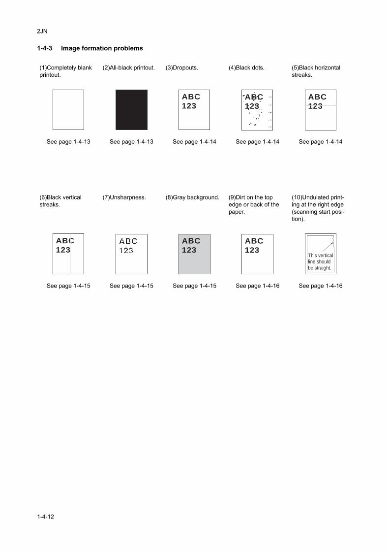
2JN
1-4-3 Image formation problems
(1)Completely blank printout.
(2)All-black printout. (3)Dropouts. (4)Black dots. (5)Black horizontal streaks.
See page 1-4-13 See page 1-4-13 See page 1-4-14 See page 1-4-14 See page 1-4-14
(6)Black vertical streaks.
(7)Unsharpness. (8)Gray background. (9)Dirt on the top edge or back of the paper.
(10)Undulated print-ing at the right edge (scanning start posi-tion).
See page 1-4-15 See page 1-4-15 See page 1-4-15 See page 1-4-16 See page 1-4-16
ABC
123ABC
123
ABC
123
ABC
123ABC
123ABC
123This vertical
line should
be straight.
1-4-12
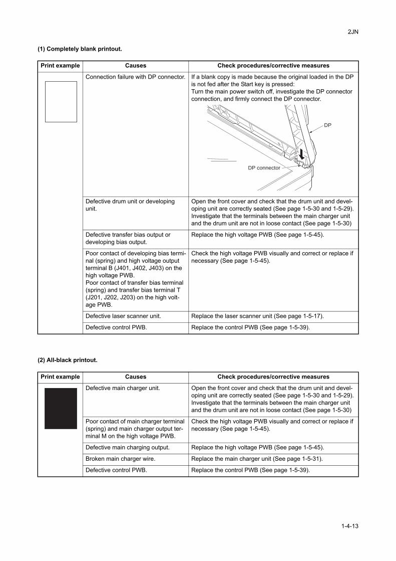
2JN
(1) Completely blank printout.
(2) All-black printout.
Print example Causes Check procedures/corrective measures
Connection failure with DP connector. If a blank copy is made because the original loaded in the DP is not fed after the Start key is pressed:Turn the main power switch off, investigate the DP connector connection, and firmly connect the DP connector.
Defective drum unit or developing unit.
Open the front cover and check that the drum unit and devel-oping unit are correctly seated (See page 1-5-30 and 1-5-29). Investigate that the terminals between the main charger unit and the drum unit are not in loose contact (See page 1-5-30)
Defective transfer bias output or developing bias output.
Replace the high voltage PWB (See page 1-5-45).
Poor contact of developing bias termi-nal (spring) and high voltage output terminal B (J401, J402, J403) on the high voltage PWB.Poor contact of transfer bias terminal (spring) and transfer bias terminal T (J201, J202, J203) on the high volt-age PWB.
Check the high voltage PWB visually and correct or replace if necessary (See page 1-5-45).
Defective laser scanner unit. Replace the laser scanner unit (See page 1-5-17).
Defective control PWB. Replace the control PWB (See page 1-5-39).
Print example Causes Check procedures/corrective measures
Defective main charger unit. Open the front cover and check that the drum unit and devel-oping unit are correctly seated (See page 1-5-30 and 1-5-29). Investigate that the terminals between the main charger unit and the drum unit are not in loose contact (See page 1-5-30)
Poor contact of main charger terminal (spring) and main charger output ter-minal M on the high voltage PWB.
Check the high voltage PWB visually and correct or replace if necessary (See page 1-5-45).
Defective main charging output. Replace the high voltage PWB (See page 1-5-45).
Broken main charger wire. Replace the main charger unit (See page 1-5-31).
Defective control PWB. Replace the control PWB (See page 1-5-39).
DP connector
DP
1-4-13
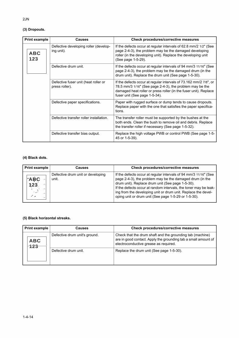
2JN
(3) Dropouts.
(4) Black dots.
(5) Black horizontal streaks.
Print example Causes Check procedures/corrective measures
Defective developing roller (develop-ing unit).
If the defects occur at regular intervals of 62.8 mm/2 1/2" (See page 2-4-3), the problem may be the damaged developing roller (in the developing unit). Replace the developing unit (See page 1-5-29).
Defective drum unit. If the defects occur at regular intervals of 94 mm/3 11/16" (See page 2-4-3), the problem may be the damaged drum (in the drum unit). Replace the drum unit (See page 1-5-30).
Defective fuser unit (heat roller or press roller).
If the defects occur at regular intervals of 73.162 mm/2 7/8", or 78.5 mm/3 1/16" (See page 2-4-3), the problem may be the damaged heat roller or press roller (in the fuser unit). Replace fuser unit (See page 1-5-34).
Defective paper specifications. Paper with rugged surface or dump tends to cause dropouts. Replace paper with the one that satisfies the paper specifica-tions.
Defective transfer roller installation. The transfer roller must be supported by the bushes at the both ends. Clean the bush to remove oil and debris. Replace the transfer roller if necessary (See page 1-5-32).
Defective transfer bias output. Replace the high voltage PWB or control PWB (See page 1-5-45 or 1-5-39).
Print example Causes Check procedures/corrective measures
Defective drum unit or developing unit.
If the defects occur at regular intervals of 94 mm/3 11/16" (See page 2-4-3), the problem may be the damaged drum (in the drum unit). Replace drum unit (See page 1-5-30).If the defects occur at random intervals, the toner may be leak-ing from the developing unit or drum unit. Replace the devel-oping unit or drum unit (See page 1-5-29 or 1-5-30).
Print example Causes Check procedures/corrective measures
Defective drum unit's ground. Check that the drum shaft and the grounding tab (machine) are in good contact. Apply the grounding tab a small amount of electroconductive grease as required.
Defective drum unit. Replace the drum unit (See page 1-5-30).
ABC
123
ABC
123
ABC
123
1-4-14
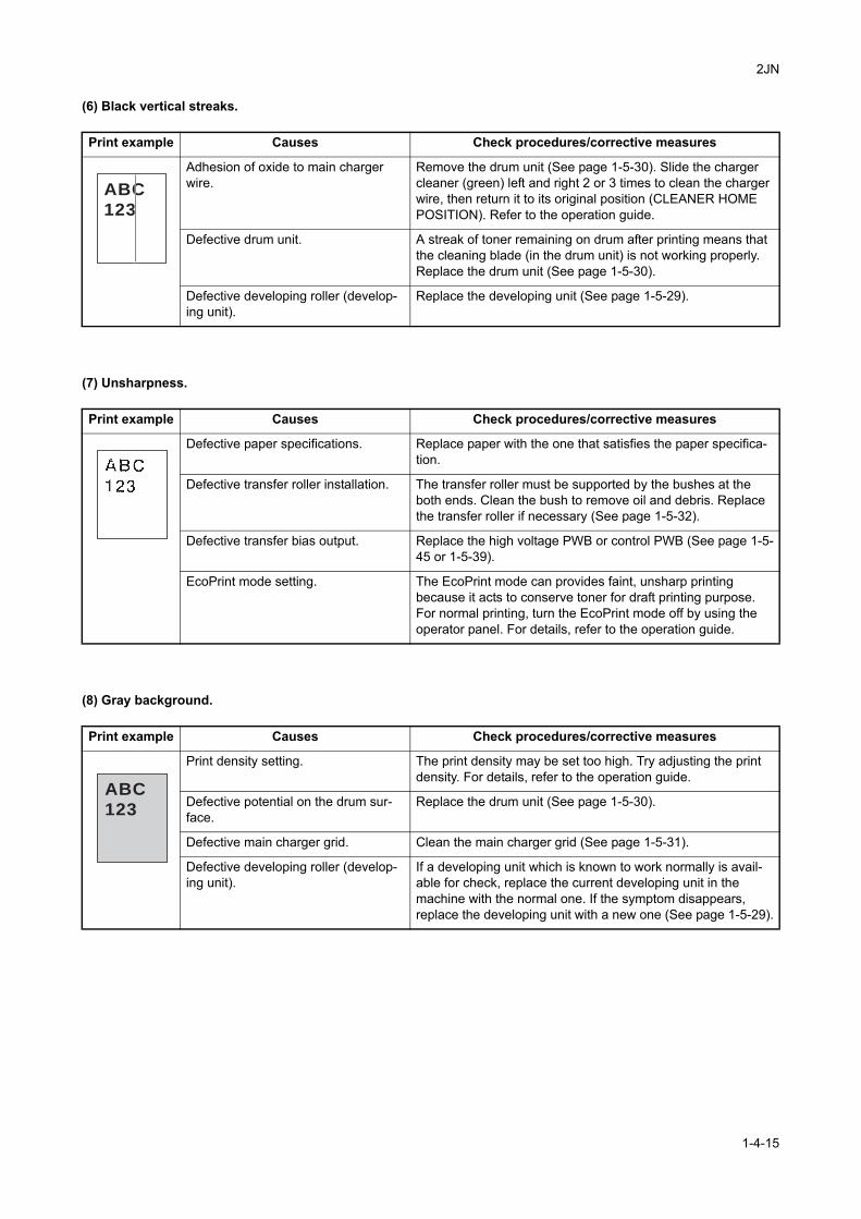
2JN
(6) Black vertical streaks.
(7) Unsharpness.
(8) Gray background.
Print example Causes Check procedures/corrective measures
Adhesion of oxide to main charger wire.
Remove the drum unit (See page 1-5-30). Slide the charger cleaner (green) left and right 2 or 3 times to clean the charger wire, then return it to its original position (CLEANER HOME POSITION). Refer to the operation guide.
Defective drum unit. A streak of toner remaining on drum after printing means that the cleaning blade (in the drum unit) is not working properly. Replace the drum unit (See page 1-5-30).
Defective developing roller (develop-ing unit).
Replace the developing unit (See page 1-5-29).
Print example Causes Check procedures/corrective measures
Defective paper specifications. Replace paper with the one that satisfies the paper specifica-tion.
Defective transfer roller installation. The transfer roller must be supported by the bushes at the both ends. Clean the bush to remove oil and debris. Replace the transfer roller if necessary (See page 1-5-32).
Defective transfer bias output. Replace the high voltage PWB or control PWB (See page 1-5-45 or 1-5-39).
EcoPrint mode setting. The EcoPrint mode can provides faint, unsharp printing because it acts to conserve toner for draft printing purpose. For normal printing, turn the EcoPrint mode off by using the operator panel. For details, refer to the operation guide.
Print example Causes Check procedures/corrective measures
Print density setting. The print density may be set too high. Try adjusting the print density. For details, refer to the operation guide.
Defective potential on the drum sur-face.
Replace the drum unit (See page 1-5-30).
Defective main charger grid. Clean the main charger grid (See page 1-5-31).
Defective developing roller (develop-ing unit).
If a developing unit which is known to work normally is avail-able for check, replace the current developing unit in the machine with the normal one. If the symptom disappears, replace the developing unit with a new one (See page 1-5-29).
ABC
123
ABC
123
1-4-15
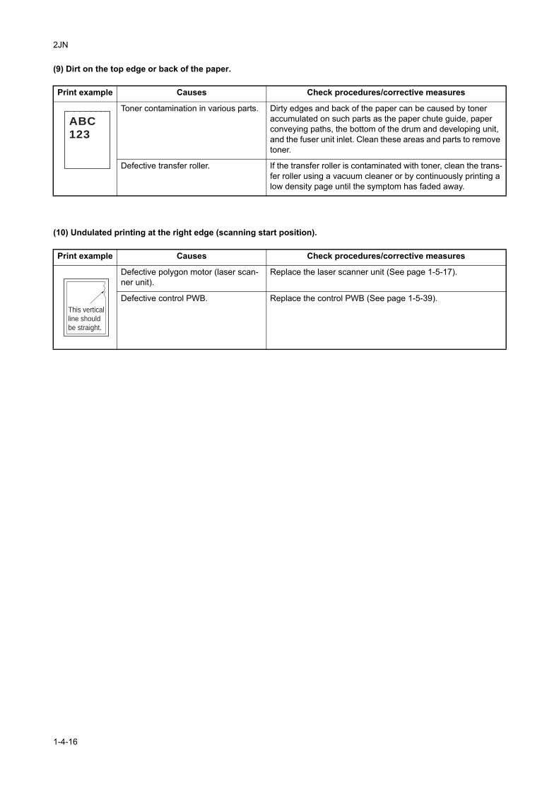
2JN
(9) Dirt on the top edge or back of the paper.
(10) Undulated printing at the right edge (scanning start position).
Print example Causes Check procedures/corrective measures
Toner contamination in various parts. Dirty edges and back of the paper can be caused by toner accumulated on such parts as the paper chute guide, paper conveying paths, the bottom of the drum and developing unit, and the fuser unit inlet. Clean these areas and parts to remove toner.
Defective transfer roller. If the transfer roller is contaminated with toner, clean the trans-fer roller using a vacuum cleaner or by continuously printing a low density page until the symptom has faded away.
Print example Causes Check procedures/corrective measures
Defective polygon motor (laser scan-ner unit).
Replace the laser scanner unit (See page 1-5-17).
Defective control PWB. Replace the control PWB (See page 1-5-39).
ABC
123
This vertical
line should
be straight.
1-4-16
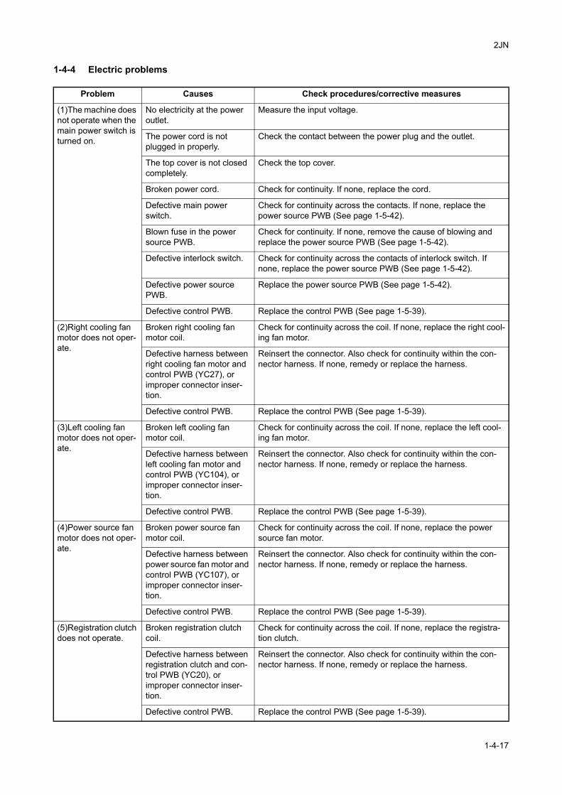
2JN
1-4-4 Electric problems
Problem Causes Check procedures/corrective measures
(1)The machine does not operate when the main power switch is turned on.
No electricity at the power outlet.
Measure the input voltage.
The power cord is not plugged in properly.
Check the contact between the power plug and the outlet.
The top cover is not closed completely.
Check the top cover.
Broken power cord. Check for continuity. If none, replace the cord.
Defective main power switch.
Check for continuity across the contacts. If none, replace the power source PWB (See page 1-5-42).
Blown fuse in the power source PWB.
Check for continuity. If none, remove the cause of blowing and replace the power source PWB (See page 1-5-42).
Defective interlock switch. Check for continuity across the contacts of interlock switch. If none, replace the power source PWB (See page 1-5-42).
Defective power source PWB.
Replace the power source PWB (See page 1-5-42).
Defective control PWB. Replace the control PWB (See page 1-5-39).
(2)Right cooling fan motor does not oper-ate.
Broken right cooling fan motor coil.
Check for continuity across the coil. If none, replace the right cool-ing fan motor.
Defective harness between right cooling fan motor and control PWB (YC27), or improper connector inser-tion.
Reinsert the connector. Also check for continuity within the con-nector harness. If none, remedy or replace the harness.
Defective control PWB. Replace the control PWB (See page 1-5-39).
(3)Left cooling fan motor does not oper-ate.
Broken left cooling fan motor coil.
Check for continuity across the coil. If none, replace the left cool-ing fan motor.
Defective harness between left cooling fan motor and control PWB (YC104), or improper connector inser-tion.
Reinsert the connector. Also check for continuity within the con-nector harness. If none, remedy or replace the harness.
Defective control PWB. Replace the control PWB (See page 1-5-39).
(4)Power source fan motor does not oper-ate.
Broken power source fan motor coil.
Check for continuity across the coil. If none, replace the power source fan motor.
Defective harness between power source fan motor and control PWB (YC107), or improper connector inser-tion.
Reinsert the connector. Also check for continuity within the con-nector harness. If none, remedy or replace the harness.
Defective control PWB. Replace the control PWB (See page 1-5-39).
(5)Registration clutch does not operate.
Broken registration clutch coil.
Check for continuity across the coil. If none, replace the registra-tion clutch.
Defective harness between registration clutch and con-trol PWB (YC20), or improper connector inser-tion.
Reinsert the connector. Also check for continuity within the con-nector harness. If none, remedy or replace the harness.
Defective control PWB. Replace the control PWB (See page 1-5-39).
1-4-17
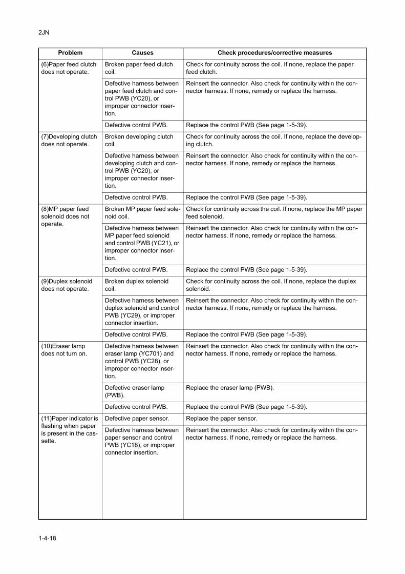
2JN
(6)Paper feed clutch does not operate.
Broken paper feed clutch coil.
Check for continuity across the coil. If none, replace the paper feed clutch.
Defective harness between paper feed clutch and con-trol PWB (YC20), or improper connector inser-tion.
Reinsert the connector. Also check for continuity within the con-nector harness. If none, remedy or replace the harness.
Defective control PWB. Replace the control PWB (See page 1-5-39).
(7)Developing clutch does not operate.
Broken developing clutch coil.
Check for continuity across the coil. If none, replace the develop-ing clutch.
Defective harness between developing clutch and con-trol PWB (YC20), or improper connector inser-tion.
Reinsert the connector. Also check for continuity within the con-nector harness. If none, remedy or replace the harness.
Defective control PWB. Replace the control PWB (See page 1-5-39).
(8)MP paper feed solenoid does not operate.
Broken MP paper feed sole-noid coil.
Check for continuity across the coil. If none, replace the MP paper feed solenoid.
Defective harness between MP paper feed solenoid and control PWB (YC21), or improper connector inser-tion.
Reinsert the connector. Also check for continuity within the con-nector harness. If none, remedy or replace the harness.
Defective control PWB. Replace the control PWB (See page 1-5-39).
(9)Duplex solenoid does not operate.
Broken duplex solenoid coil.
Check for continuity across the coil. If none, replace the duplex solenoid.
Defective harness between duplex solenoid and control PWB (YC29), or improper connector insertion.
Reinsert the connector. Also check for continuity within the con-nector harness. If none, remedy or replace the harness.
Defective control PWB. Replace the control PWB (See page 1-5-39).
(10)Eraser lamp does not turn on.
Defective harness between eraser lamp (YC701) and control PWB (YC28), or improper connector inser-tion.
Reinsert the connector. Also check for continuity within the con-nector harness. If none, remedy or replace the harness.
Defective eraser lamp (PWB).
Replace the eraser lamp (PWB).
Defective control PWB. Replace the control PWB (See page 1-5-39).
(11)Paper indicator is flashing when paper is present in the cas-sette.
Defective paper sensor. Replace the paper sensor.
Defective harness between paper sensor and control PWB (YC18), or improper connector insertion.
Reinsert the connector. Also check for continuity within the con-nector harness. If none, remedy or replace the harness.
Problem Causes Check procedures/corrective measures
1-4-18
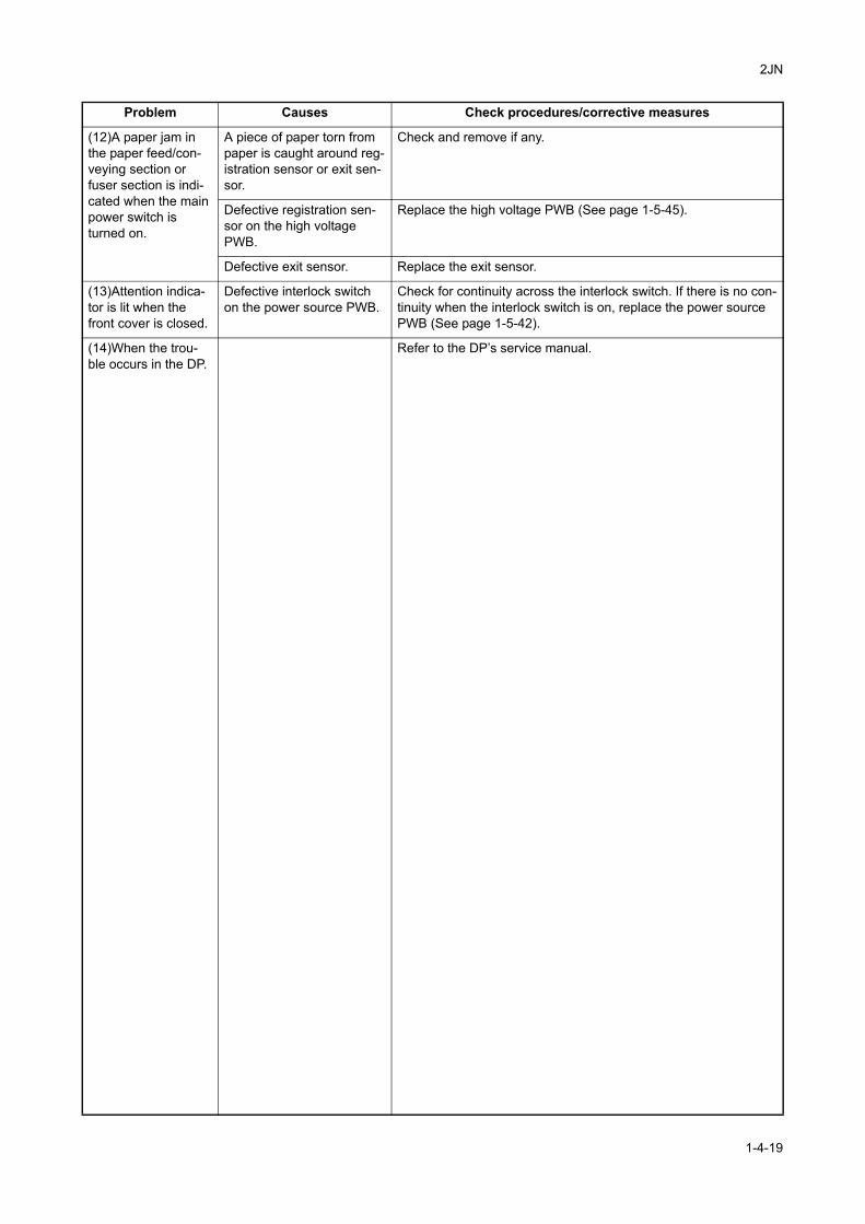
2JN
(12)A paper jam in the paper feed/con-veying section or fuser section is indi-cated when the main power switch is turned on.
A piece of paper torn from paper is caught around reg-istration sensor or exit sen-sor.
Check and remove if any.
Defective registration sen-sor on the high voltage PWB.
Replace the high voltage PWB (See page 1-5-45).
Defective exit sensor. Replace the exit sensor.
(13)Attention indica-tor is lit when the front cover is closed.
Defective interlock switch on the power source PWB.
Check for continuity across the interlock switch. If there is no con-tinuity when the interlock switch is on, replace the power source PWB (See page 1-5-42).
(14)When the trou-ble occurs in the DP.
Refer to the DP’s service manual.
Problem Causes Check procedures/corrective measures
1-4-19
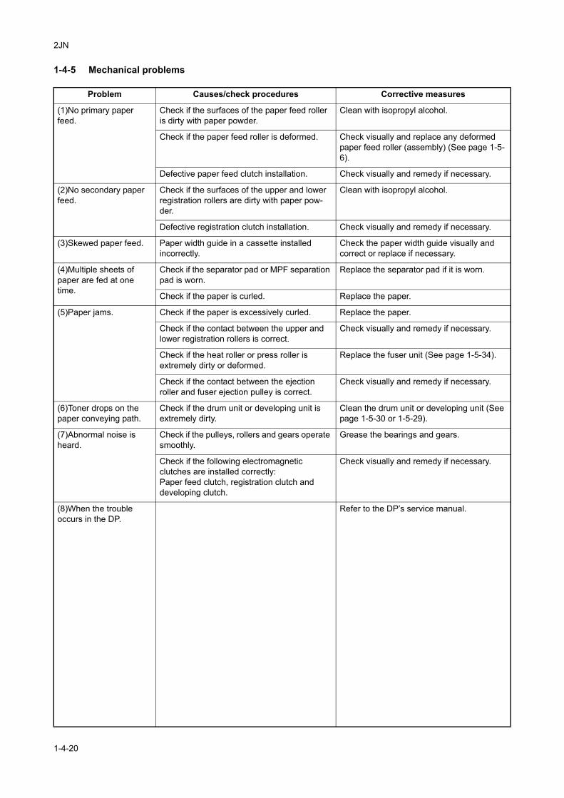
2JN
1-4-5 Mechanical problems
Problem Causes/check procedures Corrective measures
(1)No primary paper feed.
Check if the surfaces of the paper feed roller is dirty with paper powder.
Clean with isopropyl alcohol.
Check if the paper feed roller is deformed. Check visually and replace any deformed paper feed roller (assembly) (See page 1-5-6).
Defective paper feed clutch installation. Check visually and remedy if necessary.
(2)No secondary paper feed.
Check if the surfaces of the upper and lower registration rollers are dirty with paper pow-der.
Clean with isopropyl alcohol.
Defective registration clutch installation. Check visually and remedy if necessary.
(3)Skewed paper feed. Paper width guide in a cassette installed incorrectly.
Check the paper width guide visually and correct or replace if necessary.
(4)Multiple sheets of paper are fed at one time.
Check if the separator pad or MPF separation pad is worn.
Replace the separator pad if it is worn.
Check if the paper is curled. Replace the paper.
(5)Paper jams. Check if the paper is excessively curled. Replace the paper.
Check if the contact between the upper and lower registration rollers is correct.
Check visually and remedy if necessary.
Check if the heat roller or press roller is extremely dirty or deformed.
Replace the fuser unit (See page 1-5-34).
Check if the contact between the ejection roller and fuser ejection pulley is correct.
Check visually and remedy if necessary.
(6)Toner drops on the paper conveying path.
Check if the drum unit or developing unit is extremely dirty.
Clean the drum unit or developing unit (See page 1-5-30 or 1-5-29).
(7)Abnormal noise is heard.
Check if the pulleys, rollers and gears operate smoothly.
Grease the bearings and gears.
Check if the following electromagnetic clutches are installed correctly:Paper feed clutch, registration clutch and developing clutch.
Check visually and remedy if necessary.
(8)When the trouble occurs in the DP.
Refer to the DP’s service manual.
1-4-20
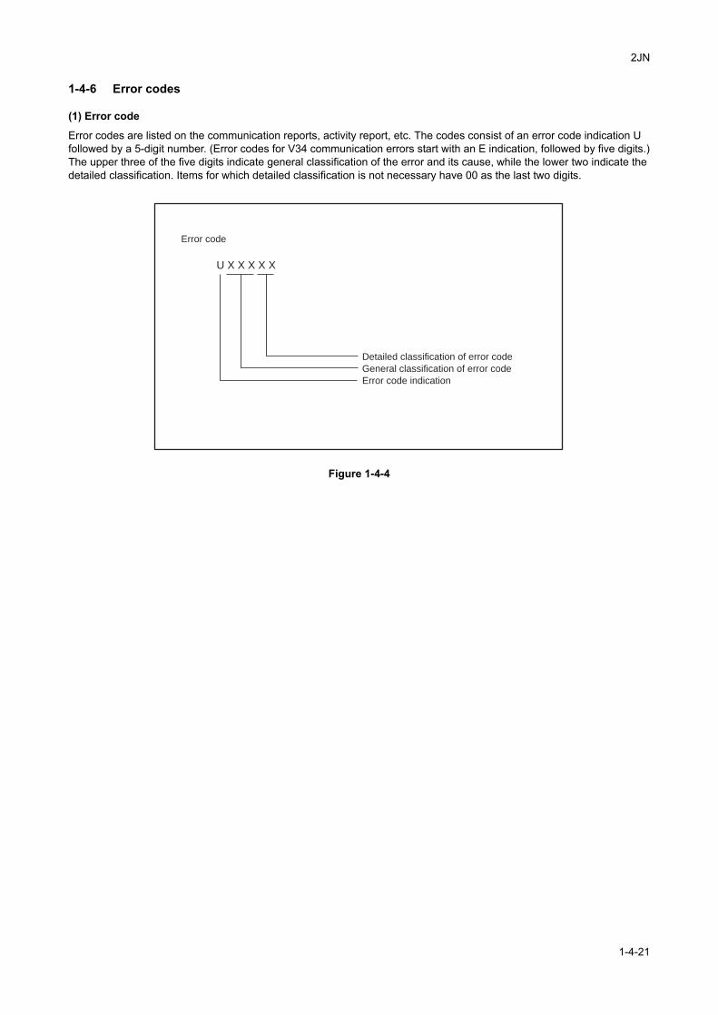
2JN
1-4-6 Error codes
(1) Error code
Error codes are listed on the communication reports, activity report, etc. The codes consist of an error code indication U followed by a 5-digit number. (Error codes for V34 communication errors start with an E indication, followed by five digits.)The upper three of the five digits indicate general classification of the error and its cause, while the lower two indicate the detailed classification. Items for which detailed classification is not necessary have 00 as the last two digits.
Figure 1-4-4
Error code
U X X X X X
Detailed classification of error code
General classification of error code
Error code indication
1-4-21
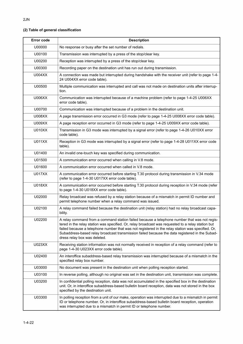
2JN
(2) Table of general classification
Error code Description
U00000 No response or busy after the set number of redials.
U00100 Transmission was interrupted by a press of the stop/clear key.
U00200 Reception was interrupted by a press of the stop/clear key.
U00300 Recording paper on the destination unit has run out during transmission.
U004XX A connection was made but interrupted during handshake with the receiver unit (refer to page 1-4-24 U004XX error code table).
U00500 Multiple communication was interrupted and call was not made on destination units after interrup-tion.
U006XX Communication was interrupted because of a machine problem (refer to page 1-4-25 U006XX error code table).
U00700 Communication was interrupted because of a problem in the destination unit.
U008XX A page transmission error occurred in G3 mode (refer to page 1-4-25 U008XX error code table).
U009XX A page reception error occurred in G3 mode (refer to page 1-4-25 U009XX error code table).
U010XX Transmission in G3 mode was interrupted by a signal error (refer to page 1-4-26 U010XX error code table).
U011XX Reception in G3 mode was interrupted by a signal error (refer to page 1-4-28 U011XX error code table).
U01400 An invalid one-touch key was specified during communication.
U01500 A communication error occurred when calling in V.8 mode.
U01600 A communication error occurred when called in V.8 mode.
U017XX A communication error occurred before starting T.30 protocol during transmission in V.34 mode (refer to page 1-4-30 U017XX error code table).
U018XX A communication error occurred before starting T.30 protocol during reception in V.34 mode (refer to page 1-4-30 U018XX error code table).
U02000 Relay broadcast was refused by a relay station because of a mismatch in permit ID number and permit telephone number when a relay command was issued.
U02100 A relay command failed because the destination unit (relay station) had no relay broadcast capa-bility.
U02200 A relay command from a command station failed because a telephone number that was not regis-tered in the relay station was specified. Or, relay broadcast was requested to a relay station but failed because a telephone number that was not registered in the relay station was specified. Or, Subaddress-based relay broadcast transmission failed because the data registered in the Subad-dress relay box was deleted.
U023XX Receiving station information was not normally received in reception of a relay command (refer to page 1-4-30 U023XX error code table).
U02400 An interoffice subaddress-based relay transmission was interrupted because of a mismatch in the specified relay box number.
U03000 No document was present in the destination unit when polling reception started.
U03100 In reverse polling, although no original was set in the destination unit, transmission was complete.
U03200 In confidential polling reception, data was not accumulated in the specified box in the destination unit. Or, in interoffice subaddress-based bulletin board reception, data was not stored in the box specified by the destination unit.
U03300 In polling reception from a unit of our make, operation was interrupted due to a mismatch in permit ID or telephone number. Or, in interoffice subaddress-based bulletin board reception, operation was interrupted due to a mismatch in permit ID or telephone number.
1-4-22
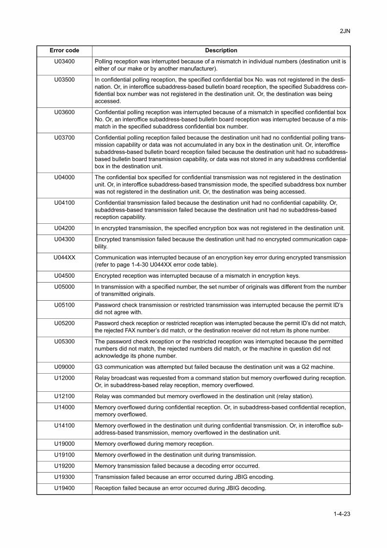
2JN
U03400 Polling reception was interrupted because of a mismatch in individual numbers (destination unit is either of our make or by another manufacturer).
U03500 In confidential polling reception, the specified confidential box No. was not registered in the desti-nation. Or, in interoffice subaddress-based bulletin board reception, the specified Subaddress con-fidential box number was not registered in the destination unit. Or, the destination was being accessed.
U03600 Confidential polling reception was interrupted because of a mismatch in specified confidential box No. Or, an interoffice subaddress-based bulletin board reception was interrupted because of a mis-match in the specified subaddress confidential box number.
U03700 Confidential polling reception failed because the destination unit had no confidential polling trans-mission capability or data was not accumulated in any box in the destination unit. Or, interoffice subaddress-based bulletin board reception failed because the destination unit had no subaddress-based bulletin board transmission capability, or data was not stored in any subaddress confidential box in the destination unit.
U04000 The confidential box specified for confidential transmission was not registered in the destination unit. Or, in interoffice subaddress-based transmission mode, the specified subaddress box number was not registered in the destination unit. Or, the destination was being accessed.
U04100 Confidential transmission failed because the destination unit had no confidential capability. Or, subaddress-based transmission failed because the destination unit had no subaddress-based reception capability.
U04200 In encrypted transmission, the specified encryption box was not registered in the destination unit.
U04300 Encrypted transmission failed because the destination unit had no encrypted communication capa-bility.
U044XX Communication was interrupted because of an encryption key error during encrypted transmission (refer to page 1-4-30 U044XX error code table).
U04500 Encrypted reception was interrupted because of a mismatch in encryption keys.
U05000 In transmission with a specified number, the set number of originals was different from the number of transmitted originals.
U05100 Password check transmission or restricted transmission was interrupted because the permit ID’s did not agree with.
U05200 Password check reception or restricted reception was interrupted because the permit ID’s did not match, the rejected FAX number’s did match, or the destination receiver did not return its phone number.
U05300 The password check reception or the restricted reception was interrupted because the permitted numbers did not match, the rejected numbers did match, or the machine in question did not acknowledge its phone number.
U09000 G3 communication was attempted but failed because the destination unit was a G2 machine.
U12000 Relay broadcast was requested from a command station but memory overflowed during reception. Or, in subaddress-based relay reception, memory overflowed.
U12100 Relay was commanded but memory overflowed in the destination unit (relay station).
U14000 Memory overflowed during confidential reception. Or, in subaddress-based confidential reception, memory overflowed.
U14100 Memory overflowed in the destination unit during confidential transmission. Or, in interoffice sub-address-based transmission, memory overflowed in the destination unit.
U19000 Memory overflowed during memory reception.
U19100 Memory overflowed in the destination unit during transmission.
U19200 Memory transmission failed because a decoding error occurred.
U19300 Transmission failed because an error occurred during JBIG encoding.
U19400 Reception failed because an error occurred during JBIG decoding.
Error code Description
1-4-23
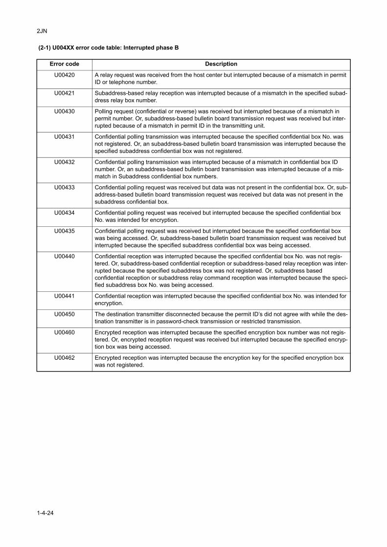
2JN
(2-1) U004XX error code table: Interrupted phase B
Error code Description
U00420 A relay request was received from the host center but interrupted because of a mismatch in permit ID or telephone number.
U00421 Subaddress-based relay reception was interrupted because of a mismatch in the specified subad-dress relay box number.
U00430 Polling request (confidential or reverse) was received but interrupted because of a mismatch in permit number. Or, subaddress-based bulletin board transmission request was received but inter-rupted because of a mismatch in permit ID in the transmitting unit.
U00431 Confidential polling transmission was interrupted because the specified confidential box No. was not registered. Or, an subaddress-based bulletin board transmission was interrupted because the specified subaddress confidential box was not registered.
U00432 Confidential polling transmission was interrupted because of a mismatch in confidential box ID number. Or, an subaddress-based bulletin board transmission was interrupted because of a mis-match in Subaddress confidential box numbers.
U00433 Confidential polling request was received but data was not present in the confidential box. Or, sub-address-based bulletin board transmission request was received but data was not present in the subaddress confidential box.
U00434 Confidential polling request was received but interrupted because the specified confidential box No. was intended for encryption.
U00435 Confidential polling request was received but interrupted because the specified confidential box was being accessed. Or, subaddress-based bulletin board transmission request was received but interrupted because the specified subaddress confidential box was being accessed.
U00440 Confidential reception was interrupted because the specified confidential box No. was not regis-tered. Or, subaddress-based confidential reception or subaddress-based relay reception was inter-rupted because the specified subaddress box was not registered. Or, subaddress based confidential reception or subaddress relay command reception was interrupted because the speci-fied subaddress box No. was being accessed.
U00441 Confidential reception was interrupted because the specified confidential box No. was intended for encryption.
U00450 The destination transmitter disconnected because the permit ID’s did not agree with while the des-tination transmitter is in password-check transmission or restricted transmission.
U00460 Encrypted reception was interrupted because the specified encryption box number was not regis-tered. Or, encrypted reception request was received but interrupted because the specified encryp-tion box was being accessed.
U00462 Encrypted reception was interrupted because the encryption key for the specified encryption box was not registered.
1-4-24
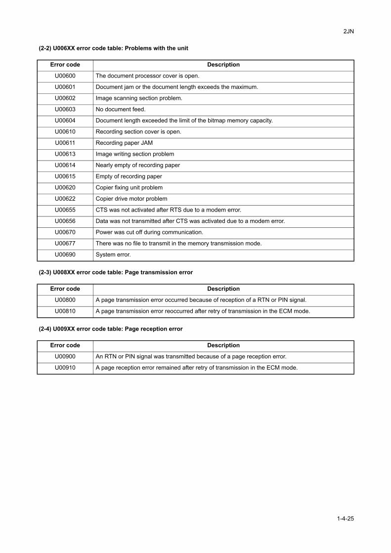
2JN
(2-2) U006XX error code table: Problems with the unit
(2-3) U008XX error code table: Page transmission error
(2-4) U009XX error code table: Page reception error
Error code Description
U00600 The document processor cover is open.
U00601 Document jam or the document length exceeds the maximum.
U00602 Image scanning section problem.
U00603 No document feed.
U00604 Document length exceeded the limit of the bitmap memory capacity.
U00610 Recording section cover is open.
U00611 Recording paper JAM
U00613 Image writing section problem
U00614 Nearly empty of recording paper
U00615 Empty of recording paper
U00620 Copier fixing unit problem
U00622 Copier drive motor problem
U00655 CTS was not activated after RTS due to a modem error.
U00656 Data was not transmitted after CTS was activated due to a modem error.
U00670 Power was cut off during communication.
U00677 There was no file to transmit in the memory transmission mode.
U00690 System error.
Error code Description
U00800 A page transmission error occurred because of reception of a RTN or PIN signal.
U00810 A page transmission error reoccurred after retry of transmission in the ECM mode.
Error code Description
U00900 An RTN or PIN signal was transmitted because of a page reception error.
U00910 A page reception error remained after retry of transmission in the ECM mode.
1-4-25
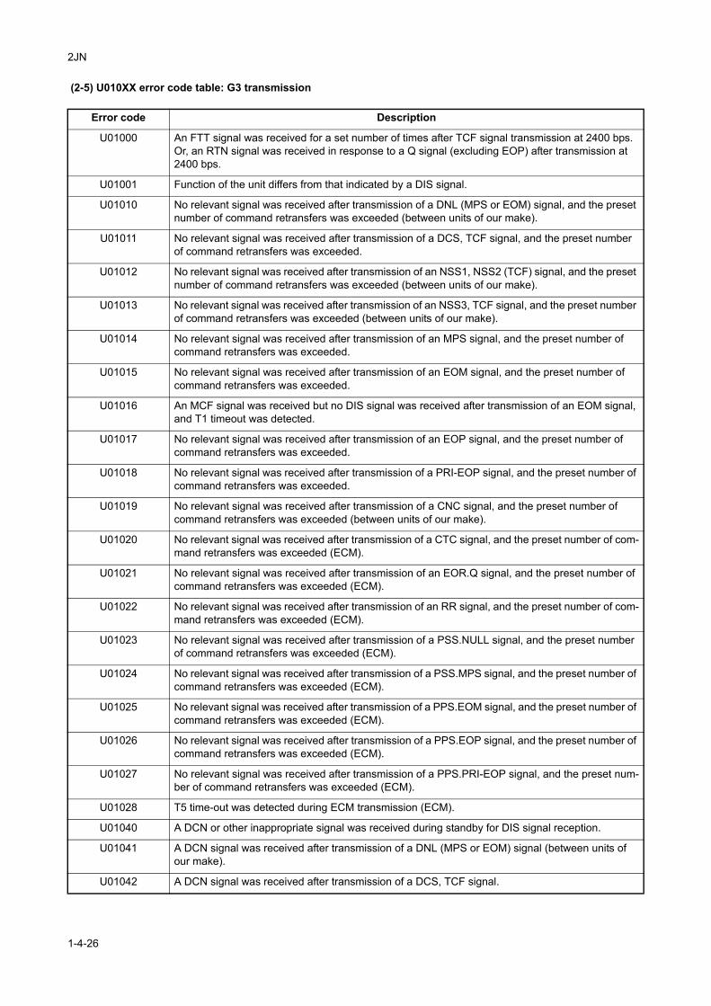
2JN
(2-5) U010XX error code table: G3 transmission
Error code Description
U01000 An FTT signal was received for a set number of times after TCF signal transmission at 2400 bps. Or, an RTN signal was received in response to a Q signal (excluding EOP) after transmission at 2400 bps.
U01001 Function of the unit differs from that indicated by a DIS signal.
U01010 No relevant signal was received after transmission of a DNL (MPS or EOM) signal, and the preset number of command retransfers was exceeded (between units of our make).
U01011 No relevant signal was received after transmission of a DCS, TCF signal, and the preset number of command retransfers was exceeded.
U01012 No relevant signal was received after transmission of an NSS1, NSS2 (TCF) signal, and the preset number of command retransfers was exceeded (between units of our make).
U01013 No relevant signal was received after transmission of an NSS3, TCF signal, and the preset number of command retransfers was exceeded (between units of our make).
U01014 No relevant signal was received after transmission of an MPS signal, and the preset number of command retransfers was exceeded.
U01015 No relevant signal was received after transmission of an EOM signal, and the preset number of command retransfers was exceeded.
U01016 An MCF signal was received but no DIS signal was received after transmission of an EOM signal, and T1 timeout was detected.
U01017 No relevant signal was received after transmission of an EOP signal, and the preset number of command retransfers was exceeded.
U01018 No relevant signal was received after transmission of a PRI-EOP signal, and the preset number of command retransfers was exceeded.
U01019 No relevant signal was received after transmission of a CNC signal, and the preset number of command retransfers was exceeded (between units of our make).
U01020 No relevant signal was received after transmission of a CTC signal, and the preset number of com-mand retransfers was exceeded (ECM).
U01021 No relevant signal was received after transmission of an EOR.Q signal, and the preset number of command retransfers was exceeded (ECM).
U01022 No relevant signal was received after transmission of an RR signal, and the preset number of com-mand retransfers was exceeded (ECM).
U01023 No relevant signal was received after transmission of a PSS.NULL signal, and the preset number of command retransfers was exceeded (ECM).
U01024 No relevant signal was received after transmission of a PSS.MPS signal, and the preset number of command retransfers was exceeded (ECM).
U01025 No relevant signal was received after transmission of a PPS.EOM signal, and the preset number of command retransfers was exceeded (ECM).
U01026 No relevant signal was received after transmission of a PPS.EOP signal, and the preset number of command retransfers was exceeded (ECM).
U01027 No relevant signal was received after transmission of a PPS.PRI-EOP signal, and the preset num-ber of command retransfers was exceeded (ECM).
U01028 T5 time-out was detected during ECM transmission (ECM).
U01040 A DCN or other inappropriate signal was received during standby for DIS signal reception.
U01041 A DCN signal was received after transmission of a DNL (MPS or EOM) signal (between units of our make).
U01042 A DCN signal was received after transmission of a DCS, TCF signal.
1-4-26
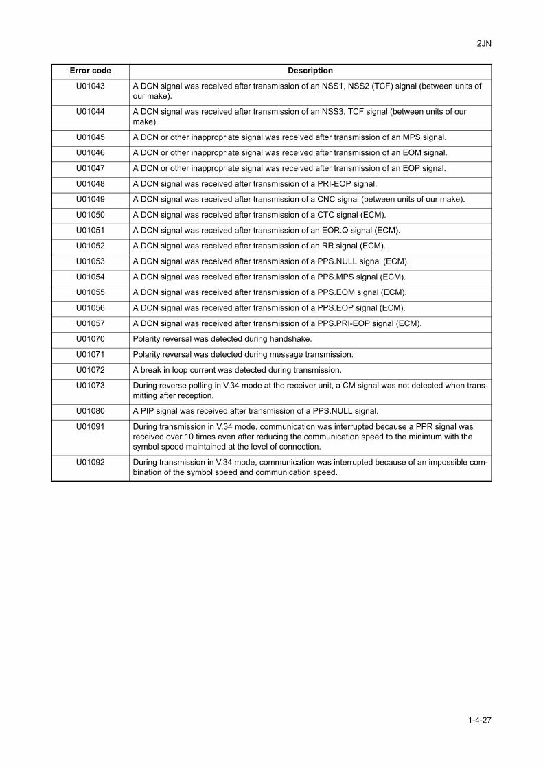
2JN
U01043 A DCN signal was received after transmission of an NSS1, NSS2 (TCF) signal (between units of our make).
U01044 A DCN signal was received after transmission of an NSS3, TCF signal (between units of our make).
U01045 A DCN or other inappropriate signal was received after transmission of an MPS signal.
U01046 A DCN or other inappropriate signal was received after transmission of an EOM signal.
U01047 A DCN or other inappropriate signal was received after transmission of an EOP signal.
U01048 A DCN signal was received after transmission of a PRI-EOP signal.
U01049 A DCN signal was received after transmission of a CNC signal (between units of our make).
U01050 A DCN signal was received after transmission of a CTC signal (ECM).
U01051 A DCN signal was received after transmission of an EOR.Q signal (ECM).
U01052 A DCN signal was received after transmission of an RR signal (ECM).
U01053 A DCN signal was received after transmission of a PPS.NULL signal (ECM).
U01054 A DCN signal was received after transmission of a PPS.MPS signal (ECM).
U01055 A DCN signal was received after transmission of a PPS.EOM signal (ECM).
U01056 A DCN signal was received after transmission of a PPS.EOP signal (ECM).
U01057 A DCN signal was received after transmission of a PPS.PRI-EOP signal (ECM).
U01070 Polarity reversal was detected during handshake.
U01071 Polarity reversal was detected during message transmission.
U01072 A break in loop current was detected during transmission.
U01073 During reverse polling in V.34 mode at the receiver unit, a CM signal was not detected when trans-mitting after reception.
U01080 A PIP signal was received after transmission of a PPS.NULL signal.
U01091 During transmission in V.34 mode, communication was interrupted because a PPR signal was received over 10 times even after reducing the communication speed to the minimum with the symbol speed maintained at the level of connection.
U01092 During transmission in V.34 mode, communication was interrupted because of an impossible com-bination of the symbol speed and communication speed.
Error code Description
1-4-27
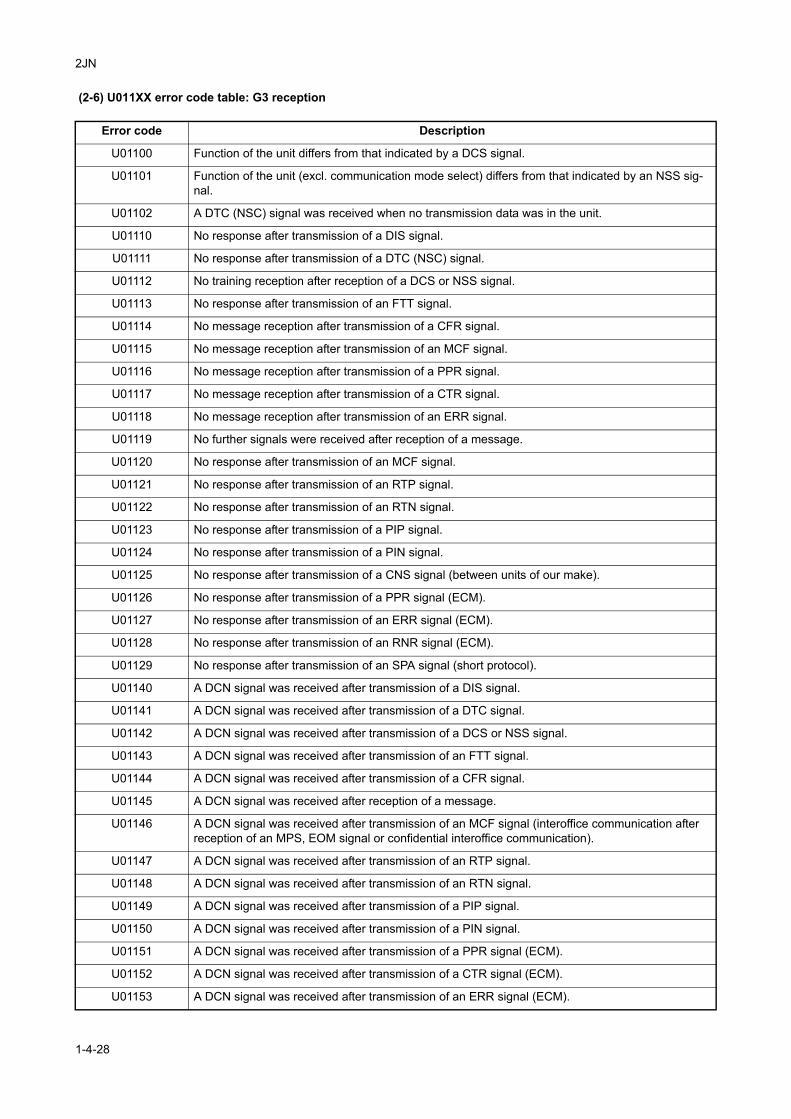
2JN
(2-6) U011XX error code table: G3 reception
Error code Description
U01100 Function of the unit differs from that indicated by a DCS signal.
U01101 Function of the unit (excl. communication mode select) differs from that indicated by an NSS sig-nal.
U01102 A DTC (NSC) signal was received when no transmission data was in the unit.
U01110 No response after transmission of a DIS signal.
U01111 No response after transmission of a DTC (NSC) signal.
U01112 No training reception after reception of a DCS or NSS signal.
U01113 No response after transmission of an FTT signal.
U01114 No message reception after transmission of a CFR signal.
U01115 No message reception after transmission of an MCF signal.
U01116 No message reception after transmission of a PPR signal.
U01117 No message reception after transmission of a CTR signal.
U01118 No message reception after transmission of an ERR signal.
U01119 No further signals were received after reception of a message.
U01120 No response after transmission of an MCF signal.
U01121 No response after transmission of an RTP signal.
U01122 No response after transmission of an RTN signal.
U01123 No response after transmission of a PIP signal.
U01124 No response after transmission of a PIN signal.
U01125 No response after transmission of a CNS signal (between units of our make).
U01126 No response after transmission of a PPR signal (ECM).
U01127 No response after transmission of an ERR signal (ECM).
U01128 No response after transmission of an RNR signal (ECM).
U01129 No response after transmission of an SPA signal (short protocol).
U01140 A DCN signal was received after transmission of a DIS signal.
U01141 A DCN signal was received after transmission of a DTC signal.
U01142 A DCN signal was received after transmission of a DCS or NSS signal.
U01143 A DCN signal was received after transmission of an FTT signal.
U01144 A DCN signal was received after transmission of a CFR signal.
U01145 A DCN signal was received after reception of a message.
U01146 A DCN signal was received after transmission of an MCF signal (interoffice communication after reception of an MPS, EOM signal or confidential interoffice communication).
U01147 A DCN signal was received after transmission of an RTP signal.
U01148 A DCN signal was received after transmission of an RTN signal.
U01149 A DCN signal was received after transmission of a PIP signal.
U01150 A DCN signal was received after transmission of a PIN signal.
U01151 A DCN signal was received after transmission of a PPR signal (ECM).
U01152 A DCN signal was received after transmission of a CTR signal (ECM).
U01153 A DCN signal was received after transmission of an ERR signal (ECM).
1-4-28
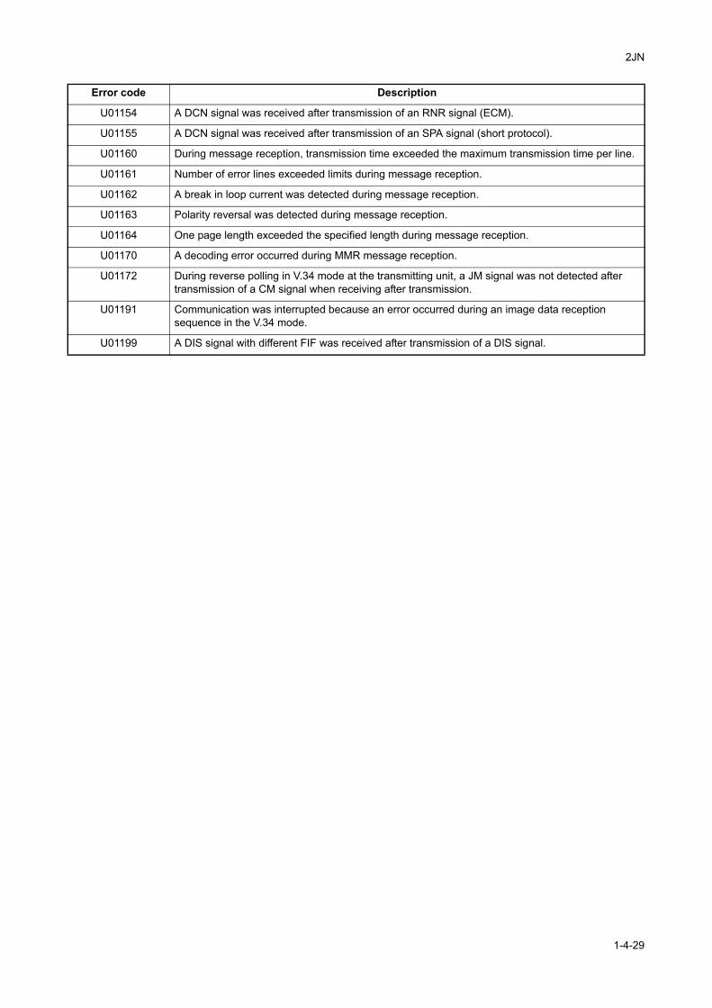
2JN
U01154 A DCN signal was received after transmission of an RNR signal (ECM).
U01155 A DCN signal was received after transmission of an SPA signal (short protocol).
U01160 During message reception, transmission time exceeded the maximum transmission time per line.
U01161 Number of error lines exceeded limits during message reception.
U01162 A break in loop current was detected during message reception.
U01163 Polarity reversal was detected during message reception.
U01164 One page length exceeded the specified length during message reception.
U01170 A decoding error occurred during MMR message reception.
U01172 During reverse polling in V.34 mode at the transmitting unit, a JM signal was not detected after transmission of a CM signal when receiving after transmission.
U01191 Communication was interrupted because an error occurred during an image data reception sequence in the V.34 mode.
U01199 A DIS signal with different FIF was received after transmission of a DIS signal.
Error code Description
1-4-29
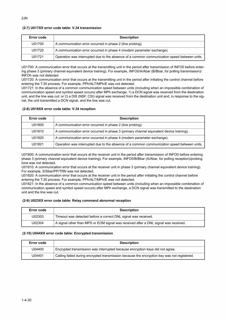
2JN
(2-7) U017XX error code table: V.34 transmission
U01700: A communication error that occurs at the transmitting unit in the period after transmission of INFO0 before enter-ing phase 3 (primary channel equivalent device training). For example, INFO0/A/Abar (B/Bbar, for polling transmission)/INFOh was not detected.U01720: A communication error that occurs at the transmitting unit in the period after initiating the control channel before entering the T.30 process. For example, PPh/ALT/MPh/E was not detected.U01721: In the absence of a common communication speed between units (including when an impossible combination of communication speed and symbol speed occurs) after MPh exchange; 1) a DCN signal was received from the destination unit, and the line was cut; or 2) a DIS (NSF, CSI) signal was received from the destination unit and, in response to the sig-nal, the unit transmitted a DCN signal, and the line was cut.
(2-8) U018XX error code table: V.34 reception
U01800: A communication error that occurs at the receiver unit in the period after transmission of INFO0 before entering phase 3 (primary channel equivalent device training). For example, INFO0/B/Bbar (A/Abar, for polling reception)/probing tone was not detected.U01810: A communication error that occurs at the receiver unit in phase 3 (primary channel equivalent device training).For example, S/Sbar/PP/TRN was not detected.U01820: A communication error that occurs at the receiver unit in the period after initiating the control channel before entering the T.30 process. For example, PPh/ALT/MPh/E was not detected.U01821: In the absence of a common communication speed between units (including when an impossible combination of communication speed and symbol speed occurs) after MPh exchange, a DCN signal was transmitted to the destination unit and the line was cut.
(2-9) U023XX error code table: Relay command abnormal reception
(2-10) U044XX error code table: Encrypted transmission
Error code Description
U01700 A communication error occurred in phase 2 (line probing).
U01720 A communication error occurred in phase 4 (modem parameter exchange).
U01721 Operation was interrupted due to the absence of a common communication speed between units.
Error code Description
U01800 A communication error occurred in phase 2 (line probing).
U01810 A communication error occurred in phase 3 (primary channel equivalent device training).
U01820 A communication error occurred in phase 4 (modem parameter exchange).
U01821 Operation was interrupted due to the absence of a common communication speed between units.
Error code Description
U02303 Timeout was detected before a correct DNL signal was received.
U02304 A signal other than MPS or EOM signal was received after a DNL signal was received.
Error code Description
U04400 Encrypted transmission was interrupted because encryption keys did not agree.
U04401 Calling failed during encrypted transmission because the encryption key was not registered.
1-4-30
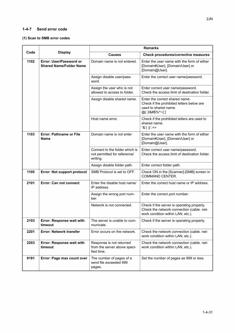
2JN
1-4-7 Send error code
(1) Scan to SMB error codes
Code DisplayRemarks
Causes Check procedures/corrective measures
1102 Error: User/Password or Shared Name/Folder Name
Domain name is not entered. Enter the user name with the form of either [Domain¥User], [Domain/User] or [Domain@User].
Assign disable user/pass-word.
Enter the correct user name/password.
Assign the user who is not allowed to access to folder.
Enter correct user name/password.Check the access limit of destination folder.
Assign disable shared name. Enter the correct shared name.Check if the prohibited letters below are used to shared name.@( )!&#$%^~[ ]`
Host name error. Check if the prohibited letters are used to shared name.“&’( )|`;<>
1103 Error: Pathname or File Name
Domain name is not enter Enter the user name with the form of either [Domain¥User], [Domain/User] or [Domain@User].
Connect to the folder which is not permitted for reference/writing.
Enter correct user name/password.Check the access limit of destination folder.
Assign disable folder path. Enter correct folder path.
1105 Error: Not support protocol SMB Protocol is set to OFF. Check ON in the [Scanner]-[SMB] screen in COMMAND CENTER.
2101 Error: Can not connect Enter the disable host name/IP address.
Enter the correct host name or IP address.
Assign the wrong port num-ber.
Enter the correct port number.
Network is not connected. Check if the server is operating properly.Check the network connection (cable. net-work condition within LAN, etc.).
2103 Error: Response wait with timeout
The server is unable to com-municate.
Check if the server is operating properly.
2201 Error: Network transfer Error occurs on the network. Check the network connection (cable. net-work condition within LAN, etc.).
2203 Error: Response wait with timeout
Response is not returned from the server above speci-fied time.
Check the network connection (cable. net-work condition within LAN, etc.).
9181 Error: Page max count over The number of pages of a send file exceeded 999 pages.
Set the number of pages as 999 or less.
1-4-31
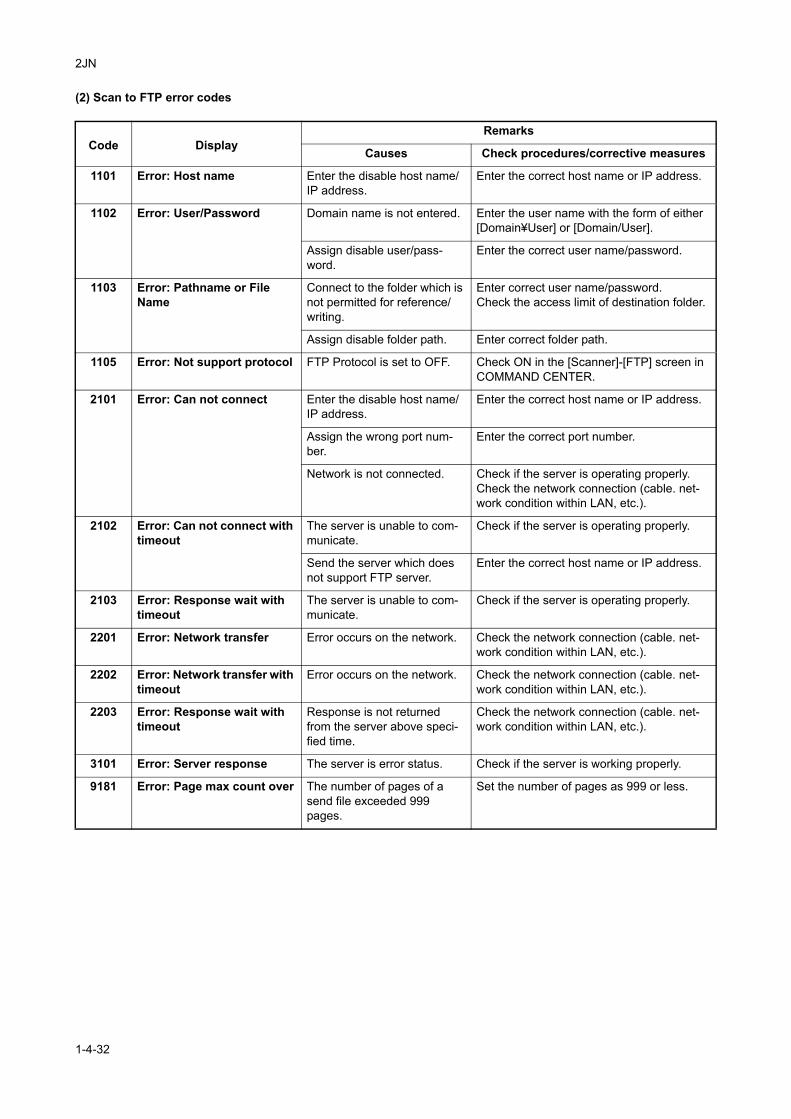
2JN
(2) Scan to FTP error codes
Code DisplayRemarks
Causes Check procedures/corrective measures
1101 Error: Host name Enter the disable host name/IP address.
Enter the correct host name or IP address.
1102 Error: User/Password Domain name is not entered. Enter the user name with the form of either [Domain¥User] or [Domain/User].
Assign disable user/pass-word.
Enter the correct user name/password.
1103 Error: Pathname or File Name
Connect to the folder which is not permitted for reference/writing.
Enter correct user name/password.Check the access limit of destination folder.
Assign disable folder path. Enter correct folder path.
1105 Error: Not support protocol FTP Protocol is set to OFF. Check ON in the [Scanner]-[FTP] screen in COMMAND CENTER.
2101 Error: Can not connect Enter the disable host name/IP address.
Enter the correct host name or IP address.
Assign the wrong port num-ber.
Enter the correct port number.
Network is not connected. Check if the server is operating properly.Check the network connection (cable. net-work condition within LAN, etc.).
2102 Error: Can not connect with timeout
The server is unable to com-municate.
Check if the server is operating properly.
Send the server which does not support FTP server.
Enter the correct host name or IP address.
2103 Error: Response wait with timeout
The server is unable to com-municate.
Check if the server is operating properly.
2201 Error: Network transfer Error occurs on the network. Check the network connection (cable. net-work condition within LAN, etc.).
2202 Error: Network transfer with timeout
Error occurs on the network. Check the network connection (cable. net-work condition within LAN, etc.).
2203 Error: Response wait with timeout
Response is not returned from the server above speci-fied time.
Check the network connection (cable. net-work condition within LAN, etc.).
3101 Error: Server response The server is error status. Check if the server is working properly.
9181 Error: Page max count over The number of pages of a send file exceeded 999 pages.
Set the number of pages as 999 or less.
1-4-32
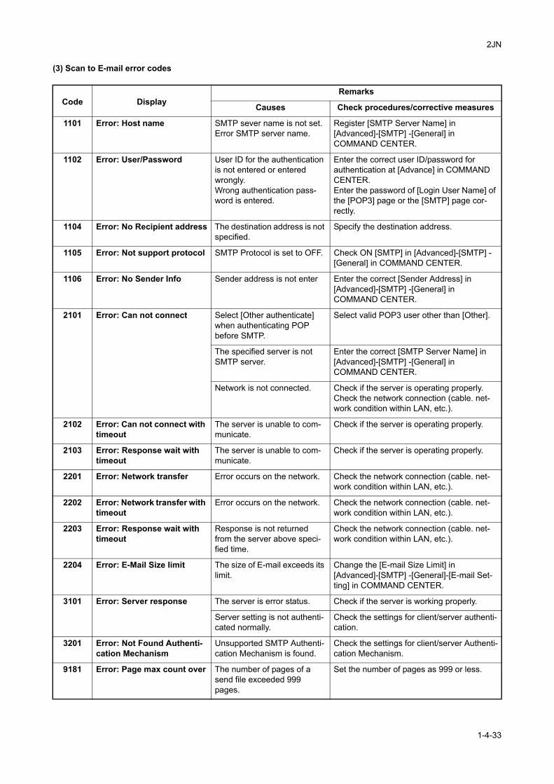
2JN
(3) Scan to E-mail error codes
Code DisplayRemarks
Causes Check procedures/corrective measures
1101 Error: Host name SMTP sever name is not set. Error SMTP server name.
Register [SMTP Server Name] in [Advanced]-[SMTP] -[General] in COMMAND CENTER.
1102 Error: User/Password User ID for the authentication is not entered or entered wrongly.Wrong authentication pass-word is entered.
Enter the correct user ID/password for authentication at [Advance] in COMMAND CENTER.Enter the password of [Login User Name] of the [POP3] page or the [SMTP] page cor-rectly.
1104 Error: No Recipient address The destination address is not specified.
Specify the destination address.
1105 Error: Not support protocol SMTP Protocol is set to OFF. Check ON [SMTP] in [Advanced]-[SMTP] -[General] in COMMAND CENTER.
1106 Error: No Sender Info Sender address is not enter Enter the correct [Sender Address] in [Advanced]-[SMTP] -[General] in COMMAND CENTER.
2101 Error: Can not connect Select [Other authenticate] when authenticating POP before SMTP.
Select valid POP3 user other than [Other].
The specified server is not SMTP server.
Enter the correct [SMTP Server Name] in [Advanced]-[SMTP] -[General] in COMMAND CENTER.
Network is not connected. Check if the server is operating properly.Check the network connection (cable. net-work condition within LAN, etc.).
2102 Error: Can not connect with timeout
The server is unable to com-municate.
Check if the server is operating properly.
2103 Error: Response wait with timeout
The server is unable to com-municate.
Check if the server is operating properly.
2201 Error: Network transfer Error occurs on the network. Check the network connection (cable. net-work condition within LAN, etc.).
2202 Error: Network transfer with timeout
Error occurs on the network. Check the network connection (cable. net-work condition within LAN, etc.).
2203 Error: Response wait with timeout
Response is not returned from the server above speci-fied time.
Check the network connection (cable. net-work condition within LAN, etc.).
2204 Error: E-Mail Size limit The size of E-mail exceeds its limit.
Change the [E-mail Size Limit] in [Advanced]-[SMTP] -[General]-[E-mail Set-ting] in COMMAND CENTER.
3101 Error: Server response The server is error status. Check if the server is working properly.
Server setting is not authenti-cated normally.
Check the settings for client/server authenti-cation.
3201 Error: Not Found Authenti-cation Mechanism
Unsupported SMTP Authenti-cation Mechanism is found.
Check the settings for client/server Authenti-cation Mechanism.
9181 Error: Page max count over The number of pages of a send file exceeded 999 pages.
Set the number of pages as 999 or less.
1-4-33
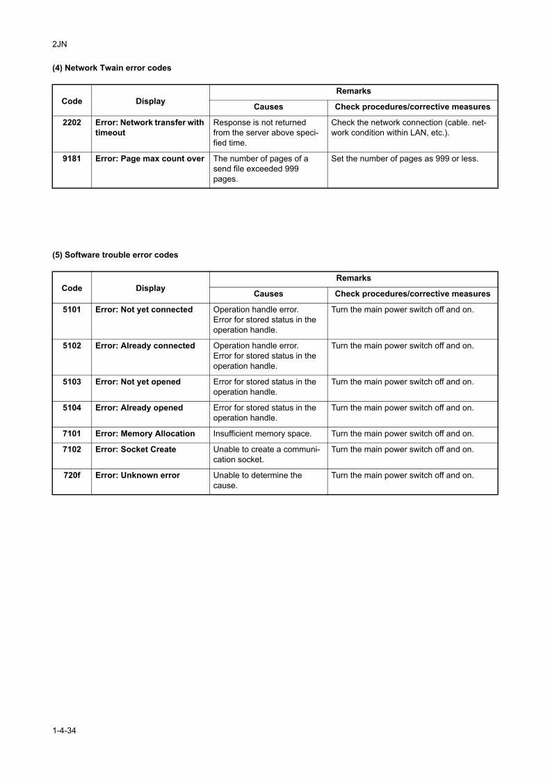
2JN
(4) Network Twain error codes
(5) Software trouble error codes
Code DisplayRemarks
Causes Check procedures/corrective measures
2202 Error: Network transfer with timeout
Response is not returned from the server above speci-fied time.
Check the network connection (cable. net-work condition within LAN, etc.).
9181 Error: Page max count over The number of pages of a send file exceeded 999 pages.
Set the number of pages as 999 or less.
Code DisplayRemarks
Causes Check procedures/corrective measures
5101 Error: Not yet connected Operation handle error.Error for stored status in the operation handle.
Turn the main power switch off and on.
5102 Error: Already connected Operation handle error.Error for stored status in the operation handle.
Turn the main power switch off and on.
5103 Error: Not yet opened Error for stored status in the operation handle.
Turn the main power switch off and on.
5104 Error: Already opened Error for stored status in the operation handle.
Turn the main power switch off and on.
7101 Error: Memory Allocation Insufficient memory space. Turn the main power switch off and on.
7102 Error: Socket Create Unable to create a communi-cation socket.
Turn the main power switch off and on.
720f Error: Unknown error Unable to determine the cause.
Turn the main power switch off and on.
1-4-34
2JN
1-5 Assembly and Disassembly
1-5-1 Precautions for assembly and disassembly
(1) Precautions
Before starting disassembly, press the Power key on the operation panel to off. Make sure that the Power lamp is off before turning off the main power switch. And then unplug the power cable from the wall outlet.When the fax kit is installed, be sure to disconnect the modular code before starting disassembly.When handling PWBs (printed wiring boards), do not touch parts with bare hands.The PWBs are susceptible to static charge.Do not touch any PWB containing ICs with bare hands or any object prone to static charge.When removing the hook of the connector, be sure to release the hook.Take care not to get the cables caught.To reassemble the parts, use the original screws. If the types and the sizes of screws are not known, refer to the PARTS LIST.
(2) Drum
Note the following when handling or storing the drum.When removing the drum unit, never expose the drum surface to strong direct light.Keep the drum at an ambient temperature between -20°C/-4°F and 40°C/104°F and at a relative humidity not higher than 90% RH. Avoid abrupt changes in temperature and humidity.Avoid exposure to any substance which is harmful to or may affect the quality of the drum.Do not touch the drum surface with any object. Should it be touched by hands or stained with oil, clean it.
(3) Toner
Store the toner container in a cool, dark place.Avoid direct light and high humidity.
1-5-1
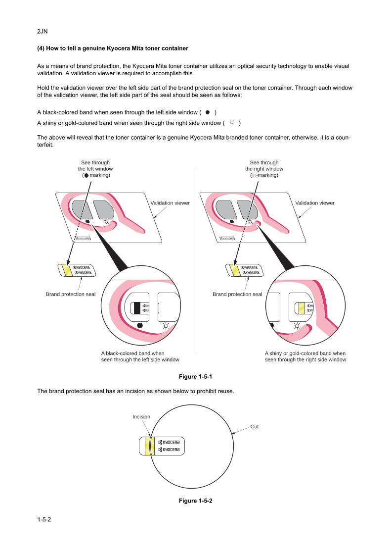
2JN
(4) How to tell a genuine Kyocera Mita toner container
As a means of brand protection, the Kyocera Mita toner container utilizes an optical security technology to enable visual validation. A validation viewer is required to accomplish this.
Hold the validation viewer over the left side part of the brand protection seal on the toner container. Through each window of the validation viewer, the left side part of the seal should be seen as follows:
A black-colored band when seen through the left side window ( )
A shiny or gold-colored band when seen through the right side window ( )
The above will reveal that the toner container is a genuine Kyocera Mita branded toner container, otherwise, it is a coun-terfeit.
Figure 1-5-1
The brand protection seal has an incision as shown below to prohibit reuse.
Figure 1-5-2
Validation viewerValidation viewer
Brand protection seal Brand protection seal
See through
the left window
( marking)
See through
the right window
( marking)
A shiny or gold-colored band when
seen through the right side window
A black-colored band when
seen through the left side window
Incision
Cut
1-5-2
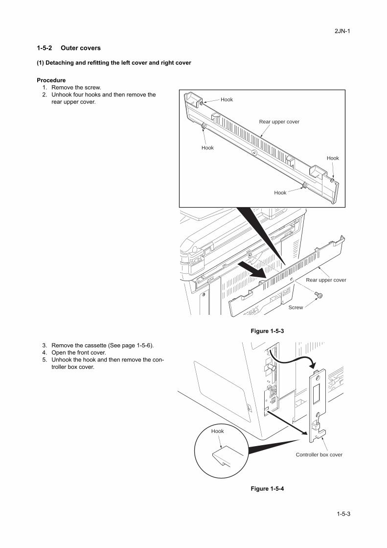
2JN-1
1-5-2 Outer covers
(1) Detaching and refitting the left cover and right cover
Procedure1. Remove the screw.2. Unhook four hooks and then remove the
rear upper cover.
Figure 1-5-3
3. Remove the cassette (See page 1-5-6).4. Open the front cover.5. Unhook the hook and then remove the con-
troller box cover.
Figure 1-5-4
Screw
Hook
Hook
Hook
Hook
Rear upper cover
Rear upper cover
Controller box cover
Hook
1-5-3
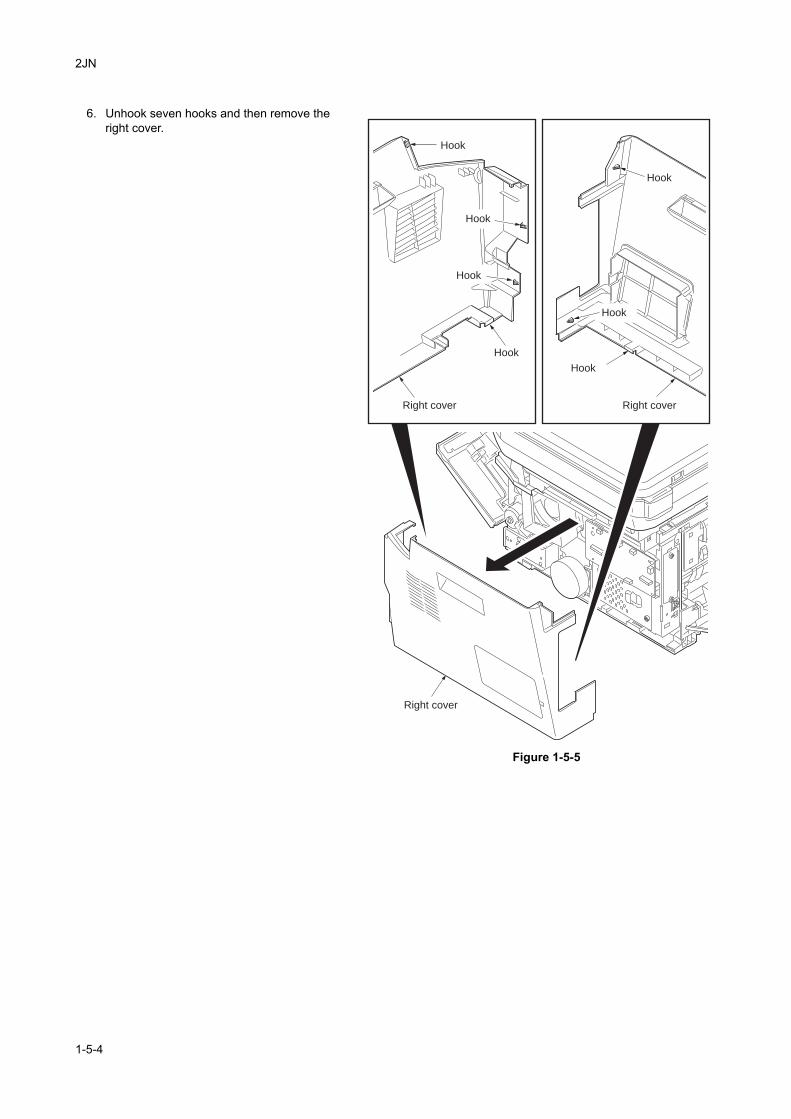
2JN
6. Unhook seven hooks and then remove the right cover.
Figure 1-5-5
Right cover
Right cover
Right cover
Hook
Hook
Hook
Hook
Hook
Hook
Hook
1-5-4
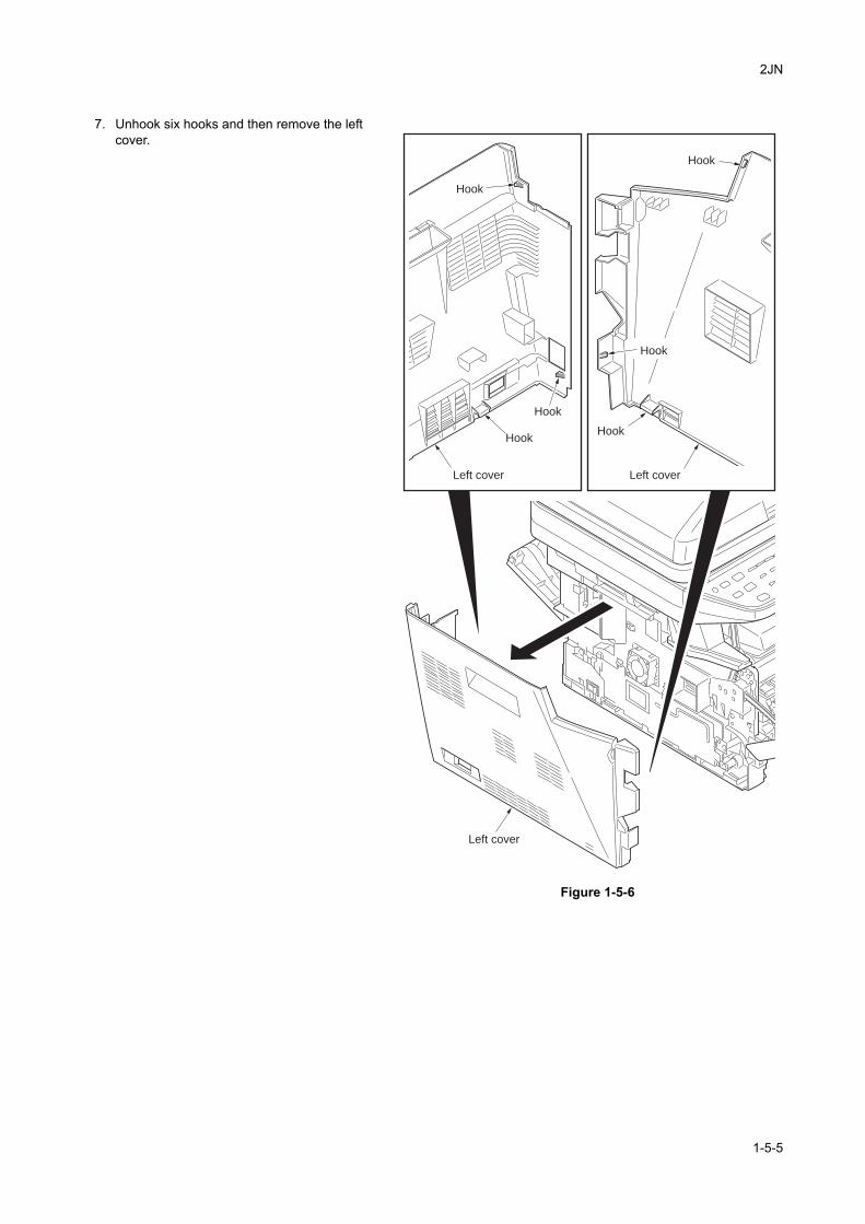
2JN
7. Unhook six hooks and then remove the left cover.
Figure 1-5-6
Left cover
Left cover
Left cover
HookHook
Hook
Hook
Hook
Hook
1-5-5
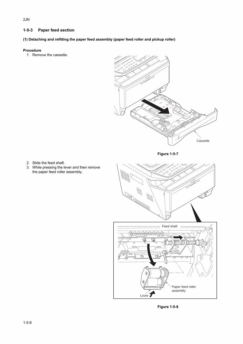
2JN
1-5-3 Paper feed section
(1) Detaching and refitting the paper feed assembly (paper feed roller and pickup roller)
Procedure1. Remove the cassette.
Figure 1-5-7
2. Slide the feed shaft.3. While pressing the lever and then remove
the paper feed roller assembly.
Figure 1-5-8
Cassette
Lever
Feed shaft
Paper feed roller
assembly
1-5-6
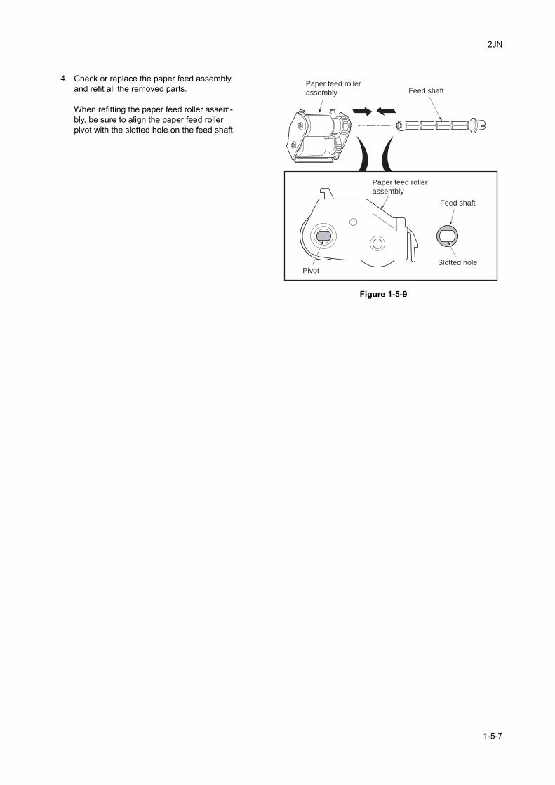
2JN
4. Check or replace the paper feed assembly and refit all the removed parts.
When refitting the paper feed roller assem-bly, be sure to align the paper feed roller pivot with the slotted hole on the feed shaft.
Figure 1-5-9
Paper feed roller
assembly
Paper feed roller
assembly
Feed shaft
Feed shaft
PivotSlotted hole
1-5-7
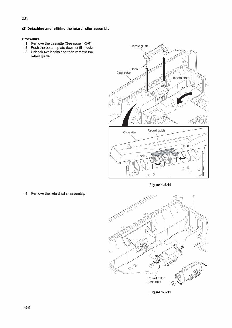
2JN
(2) Detaching and refitting the retard roller assembly
Procedure1. Remove the cassette (See page 1-5-6).2. Push the bottom plate down until it locks.3. Unhook two hooks and then remove the
retard guide.
Figure 1-5-10
4. Remove the retard roller assembly.
Figure 1-5-11
Retard guide
Retard guide
Cassestte
Cassette
Hook
Hook
Hook
Hook
Bottom plate
�
�Retard roller
Assembly
1-5-8
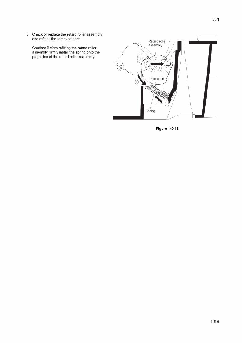
2JN
5. Check or replace the retard roller assembly and refit all the removed parts.
Caution: Before refitting the retard roller assembly, firmly install the spring onto the projection of the retard roller assembly.
Figure 1-5-12
Spring
Retard roller
assembly
Projection
1-5-9
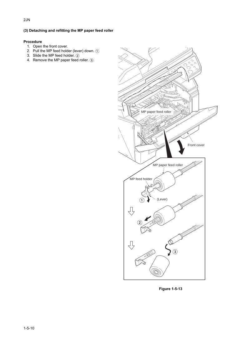
2JN
(3) Detaching and refitting the MP paper feed roller
Procedure1. Open the front cover.2. Pull the MP feed holder (lever) down. �3. Slide the MP feed holder. �4. Remove the MP paper feed roller. �
Figure 1-5-13
�
�
�
MP feed holder
(Lever)
Front cover
MP paper feed roller
MP paper feed roller
1-5-10
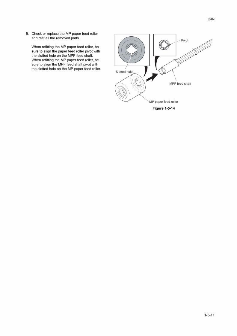
2JN
5. Check or replace the MP paper feed roller and refit all the removed parts.
When refitting the MP paper feed roller, be sure to align the paper feed roller pivot with the slotted hole on the MPF feed shaft.When refitting the MP paper feed roller, be sure to align the MPF feed shaft pivot with the slotted hole on the MP paper feed roller.
Figure 1-5-14
MPF feed shaft
Pivot
MP paper feed roller
Slotted hole
1-5-11
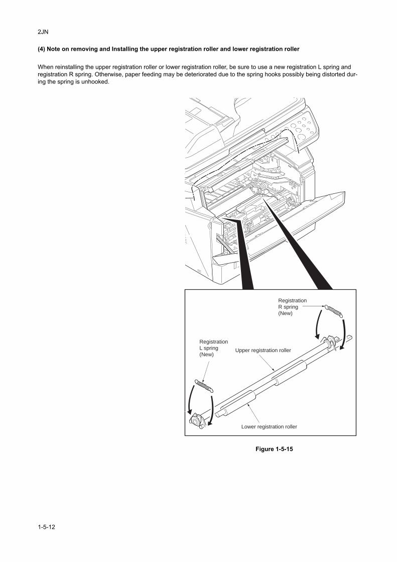
2JN
(4) Note on removing and Installing the upper registration roller and lower registration roller
When reinstalling the upper registration roller or lower registration roller, be sure to use a new registration L spring and registration R spring. Otherwise, paper feeding may be deteriorated due to the spring hooks possibly being distorted dur-ing the spring is unhooked.
Figure 1-5-15
Upper registration roller
Lower registration roller
Registration
L spring
(New)
Registration
R spring
(New)
1-5-12
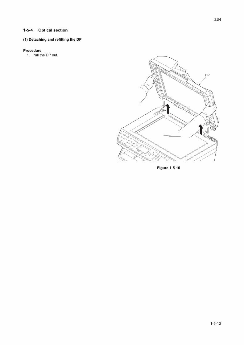
2JN
1-5-4 Optical section
(1) Detaching and refitting the DP
Procedure1. Pull the DP out.
Figure 1-5-16
DP
1-5-13
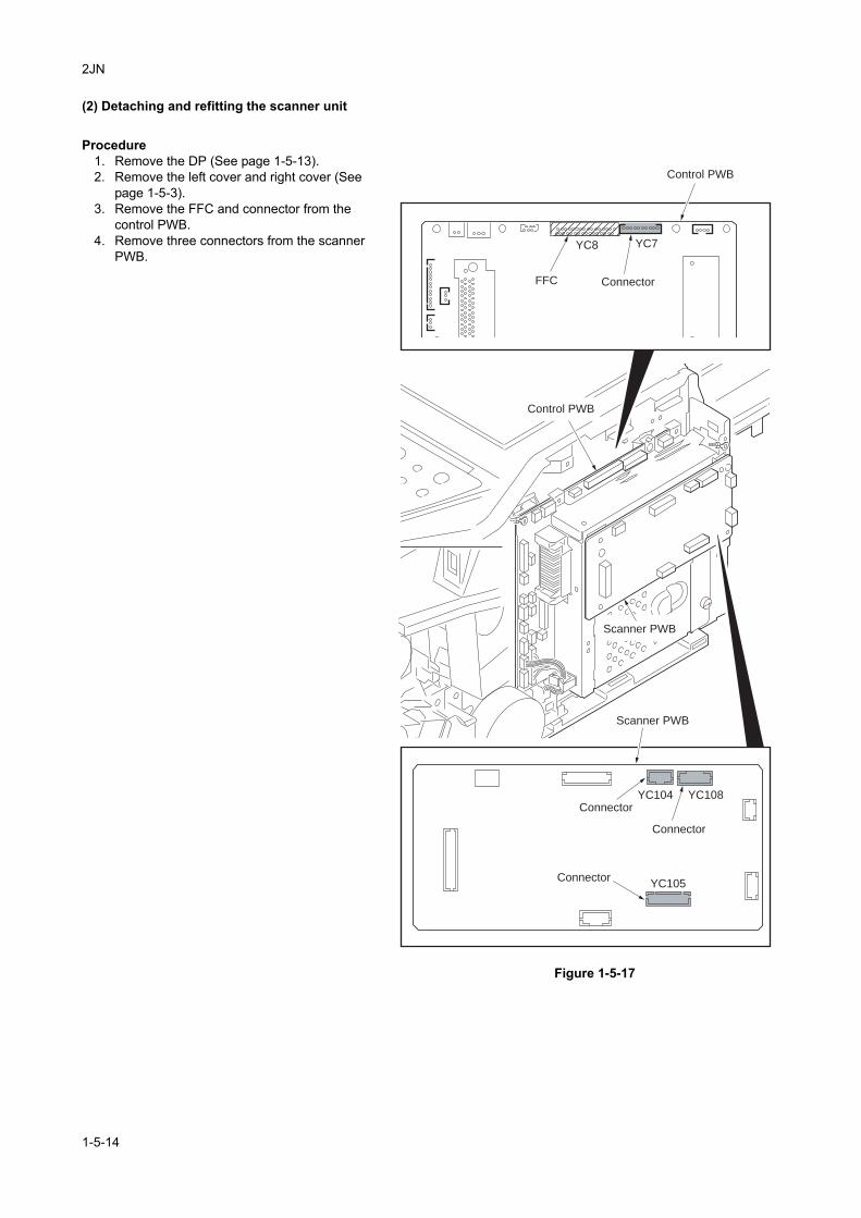
2JN
(2) Detaching and refitting the scanner unit
Procedure1. Remove the DP (See page 1-5-13).2. Remove the left cover and right cover (See
page 1-5-3).3. Remove the FFC and connector from the
control PWB.4. Remove three connectors from the scanner
PWB.
Figure 1-5-17
ConnectorFFC
Scanner PWB
Scanner PWB
Connector
Connector
Connector
YC8 YC7
YC108YC104
YC105
Control PWB
Control PWB
1-5-14
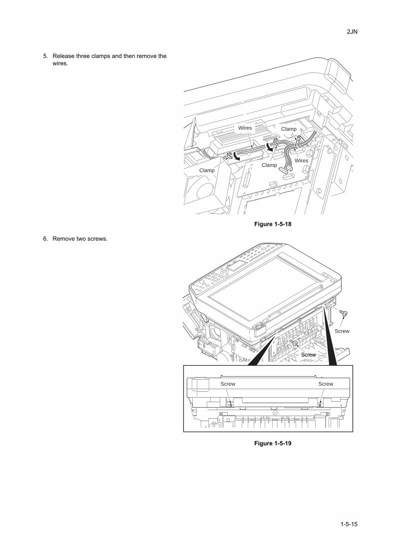
2JN
5. Release three clamps and then remove the wires.
Figure 1-5-18
6. Remove two screws.
Figure 1-5-19
Wires
Wires
Clamp
ClampClamp
Screw Screw
Screw
ScrewScrew
1-5-15
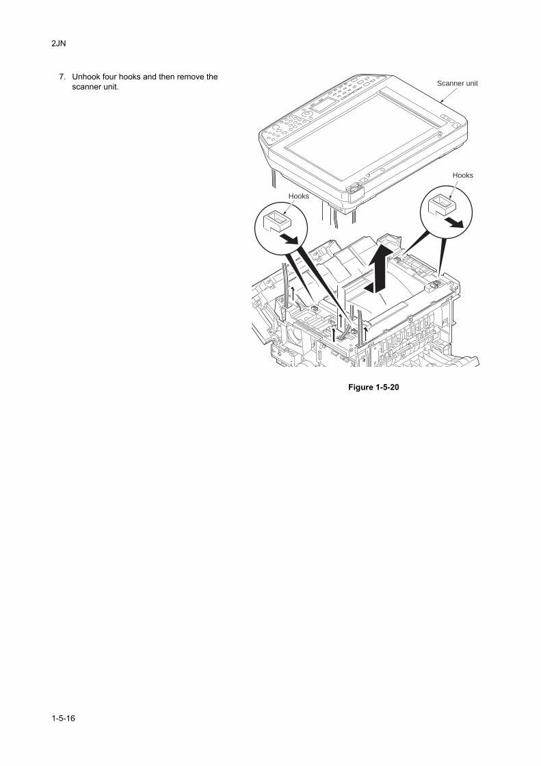
2JN
7. Unhook four hooks and then remove the scanner unit.
Figure 1-5-20
Scanner unit
Hooks
Hooks
1-5-16
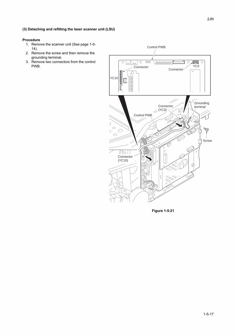
2JN
(3) Detaching and refitting the laser scanner unit (LSU)
Procedure1. Remove the scanner unit (See page 1-5-
14).2. Remove the screw and then remove the
grounding terminal.3. Remove two connectors from the control
PWB.
Figure 1-5-21
Control PWB
ConnectorConnector
YC3
YC10
Screw
Grounding
terminal
Connector
(YC10)
Connector
(YC3)
Control PWB
1-5-17
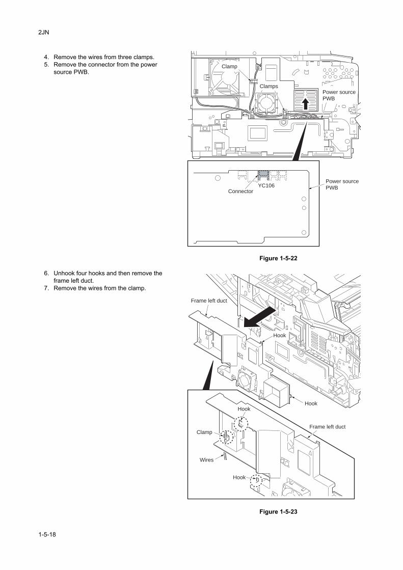
2JN
4. Remove the wires from three clamps.5. Remove the connector from the power
source PWB.
Figure 1-5-22
6. Unhook four hooks and then remove the frame left duct.
7. Remove the wires from the clamp.
Figure 1-5-23
Clamp
Clamps
Connector
Power source
PWB
Power source
PWBYC106
Frame left duct
Frame left duct
HookHook
Clamp
Wires
Hook
Hook
1-5-18
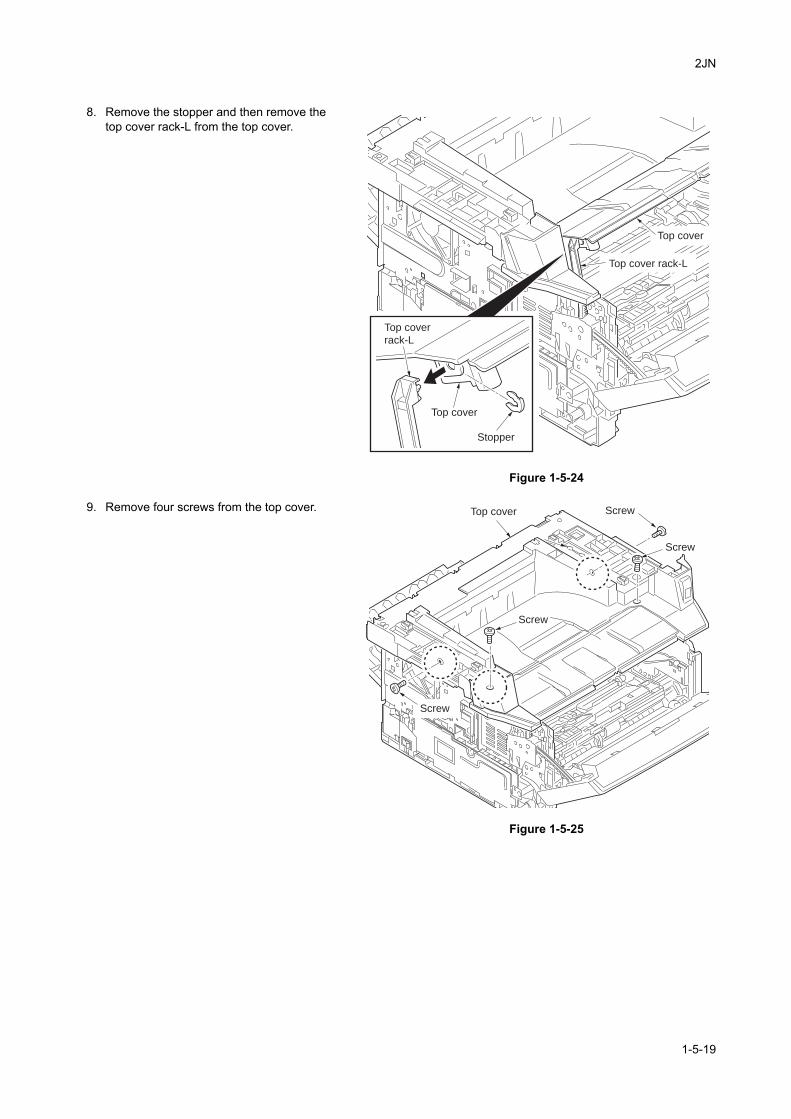
2JN
8. Remove the stopper and then remove the top cover rack-L from the top cover.
Figure 1-5-24
9. Remove four screws from the top cover.
Figure 1-5-25
Top cover
rack-L
Stopper
Top cover
Top cover
Top cover rack-L
Top cover Screw
Screw
Screw
Screw
1-5-19
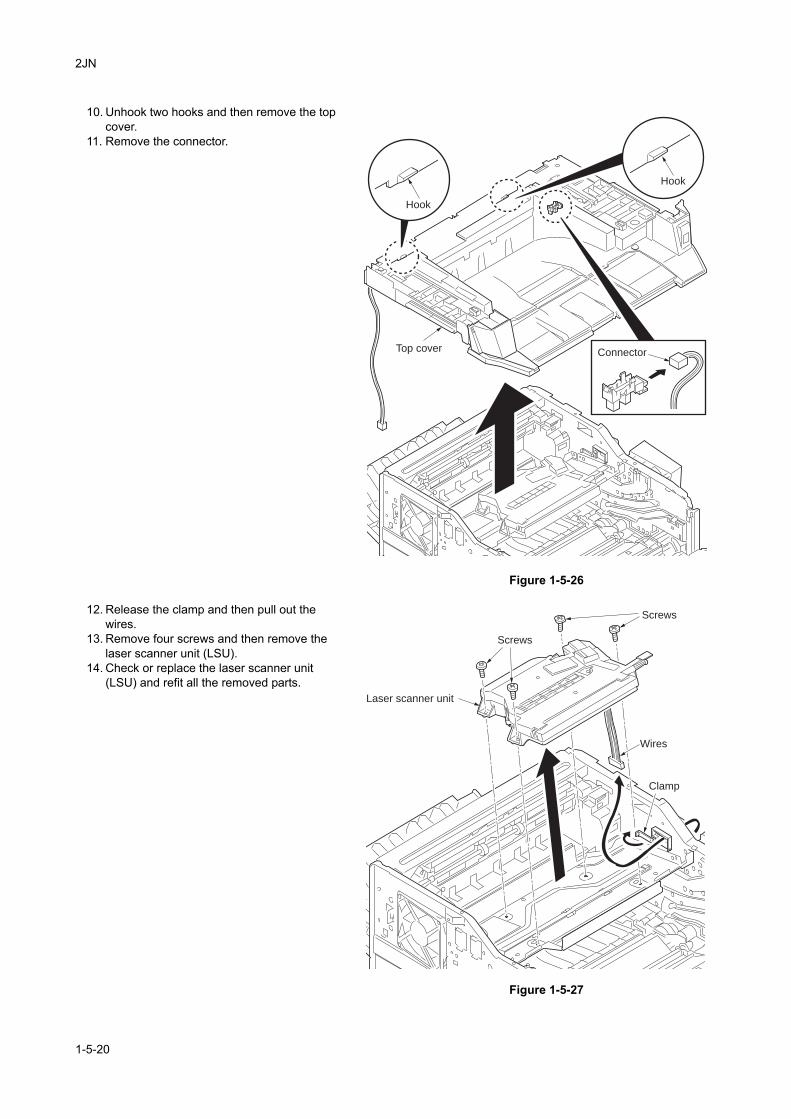
2JN
10. Unhook two hooks and then remove the top cover.
11. Remove the connector.
Figure 1-5-26
12. Release the clamp and then pull out the wires.
13. Remove four screws and then remove the laser scanner unit (LSU).
14. Check or replace the laser scanner unit (LSU) and refit all the removed parts.
Figure 1-5-27
Top cover Connector
Hook
Hook
Laser scanner unit
Wires
Clamp
Screws
Screws
1-5-20
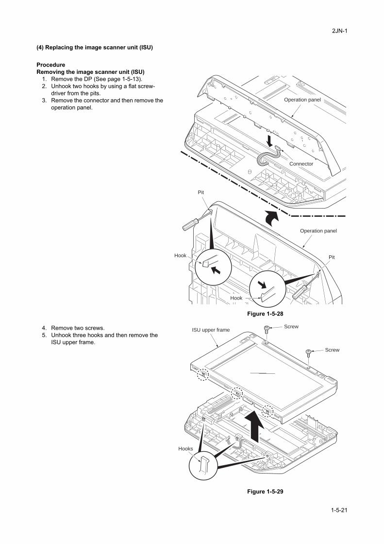
2JN-1
(4) Replacing the image scanner unit (ISU)
ProcedureRemoving the image scanner unit (ISU)
1. Remove the DP (See page 1-5-13).2. Unhook two hooks by using a flat screw-
driver from the pits.3. Remove the connector and then remove the
operation panel.
Figure 1-5-28
4. Remove two screws.5. Unhook three hooks and then remove the
ISU upper frame.
Figure 1-5-29
Hook
Pit
Pit
Connector
Operation panel
Operation panel
Hook
ISU upper frameScrew
Screw
Hooks
1-5-21
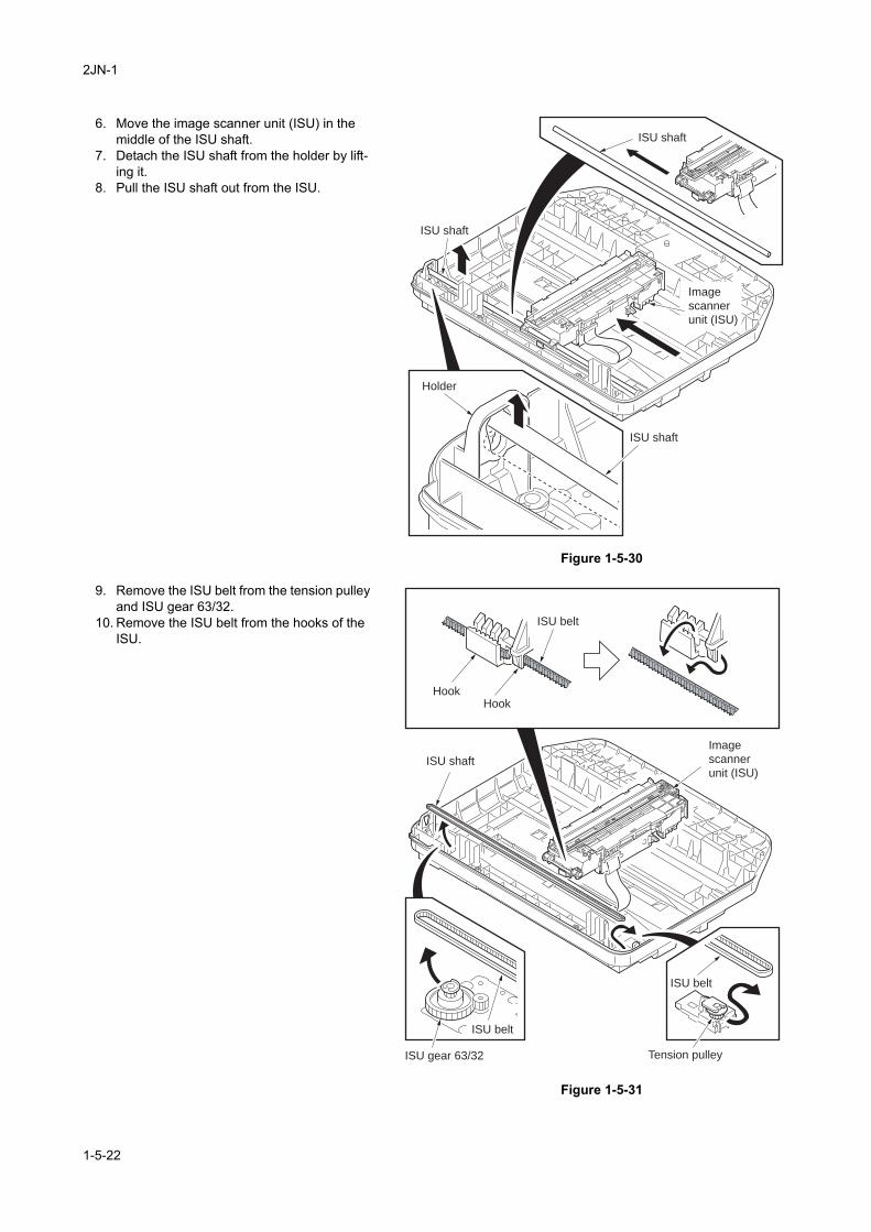
2JN-1
6. Move the image scanner unit (ISU) in the middle of the ISU shaft.
7. Detach the ISU shaft from the holder by lift-ing it.
8. Pull the ISU shaft out from the ISU.
Figure 1-5-30
9. Remove the ISU belt from the tension pulley and ISU gear 63/32.
10. Remove the ISU belt from the hooks of the ISU.
Figure 1-5-31
ISU shaft
ISU shaft
ISU shaft
Holder
Image
scanner
unit (ISU)
ISU gear 63/32 Tension pulley
Image
scanner
unit (ISU)ISU shaft
ISU belt
ISU belt
ISU belt
HookHook
1-5-22
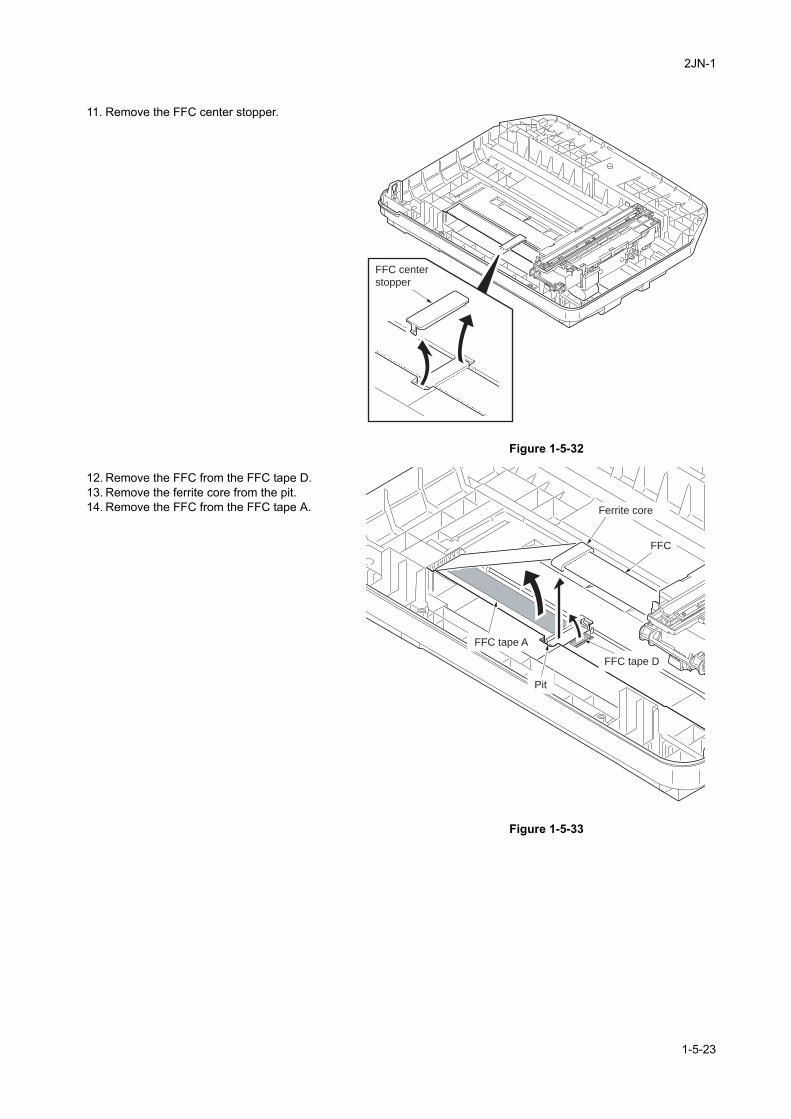
2JN-1
11. Remove the FFC center stopper.
Figure 1-5-32
12. Remove the FFC from the FFC tape D.13. Remove the ferrite core from the pit.14. Remove the FFC from the FFC tape A.
Figure 1-5-33
FFC center
stopper
Ferrite core
FFC tape A
Pit
FFC
FFC tape D
1-5-23
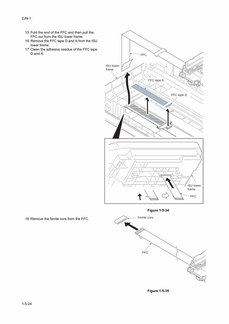
2JN-1
15. Fold the end of the FFC and then pull the FFC out from the ISU lower frame.
16. Remove the FFC tape D and A from the ISU lower frame.
17. Clean the adhesive residue of the FFC tape D and A.
Figure 1-5-34
18. Remove the ferrite core from the FFC.
Figure 1-5-35
FFC
FFC
ISU lower
frame
ISU lower
frame
FFC tape A
FFC tape D
Ferrite core
FFC
1-5-24
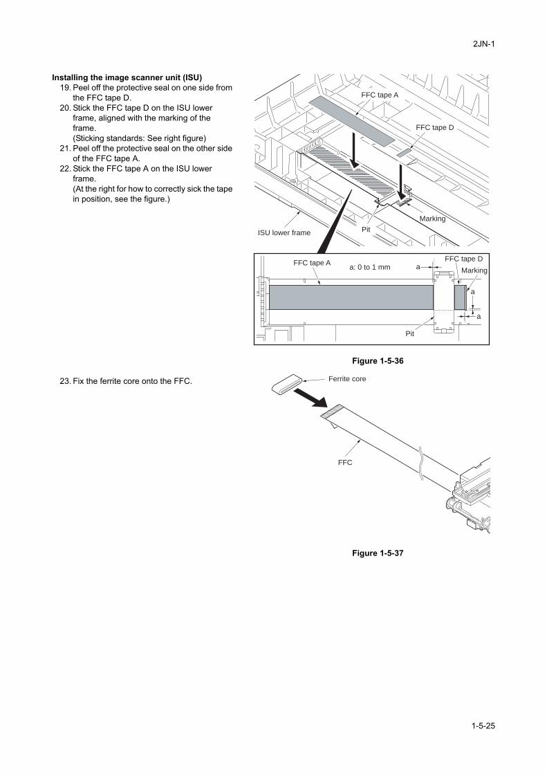
2JN-1
Installing the image scanner unit (ISU)19. Peel off the protective seal on one side from
the FFC tape D.20. Stick the FFC tape D on the ISU lower
frame, aligned with the marking of the frame.(Sticking standards: See right figure)
21. Peel off the protective seal on the other side of the FFC tape A.
22. Stick the FFC tape A on the ISU lower frame.(At the right for how to correctly sick the tape in position, see the figure.)
Figure 1-5-36
23. Fix the ferrite core onto the FFC.
Figure 1-5-37
a
aa: 0 to 1 mm
a
FFC tape A
FFC tape A
FFC tape D
Pit
Pit
FFC tape D
Marking
Marking
ISU lower frame
Ferrite core
FFC
1-5-25
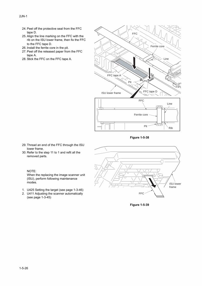
2JN-1
24. Peel off the protective seal from the FFC tape D.
25. Align the line marking on the FFC with the rib on the ISU lower frame, then fix the FFC to the FFC tape D.
26. Install the ferrite core in the pit.27. Peel off the released paper from the FFC
tape A.28. Stick the FFC on the FFC tape A.
Figure 1-5-38
29. Thread an end of the FFC through the ISU lower frame.
30. Refer to the step 11 to 1 and refit all the removed parts.
NOTE:When the replacing the image scanner unit (ISU), perform following maintenance modes.
1. U425 Setting the target (see page 1-3-46)2. U411 Adjusting the scanner automatically
(see page 1-3-45)
Figure 1-5-39
Ferrite core
Ferrite core
FFC tape A
Pit
Pit
FFC
FFC tape DISU lower frame
FFCLine
Rib
Line
FFC
ISU lower
frame
1-5-26
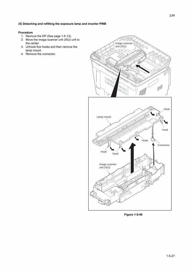
2JN
(5) Detaching and refitting the exposure lamp and inverter PWB
Procedure1. Remove the DP (See page 1-5-13).2. Move the image scanner unit (ISU) unit to
the center.3. Unhook five hooks and then remove the
lamp mount.4. Remove the connector.
Figure 1-5-40
HookHook
Hook
Hook
Hook
Lamp mount
Connector
Image scanner
unit (ISU)
Image scanner
unit (ISU)
1-5-27
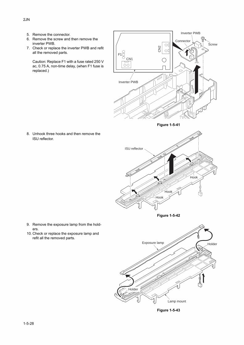
2JN
5. Remove the connector.6. Remove the screw and then remove the
inverter PWB.7. Check or replace the inverter PWB and refit
all the removed parts.
Caution: Replace F1 with a fuse rated 250 V ac, 0.75 A, non-time delay, (when F1 fuse is replaced.)
Figure 1-5-41
8. Unhook three hooks and then remove the ISU reflector.
Figure 1-5-42
9. Remove the exposure lamp from the hold-ers.
10. Check or replace the exposure lamp and refit all the removed parts.
Figure 1-5-43
Inverter PWB
Inverter PWB
ScrewConnector
CN
2
CN1
F1
ISU reflector
Hook
Hook
Hook
Holder
Holder
Exposure lamp
Lamp mount
1-5-28
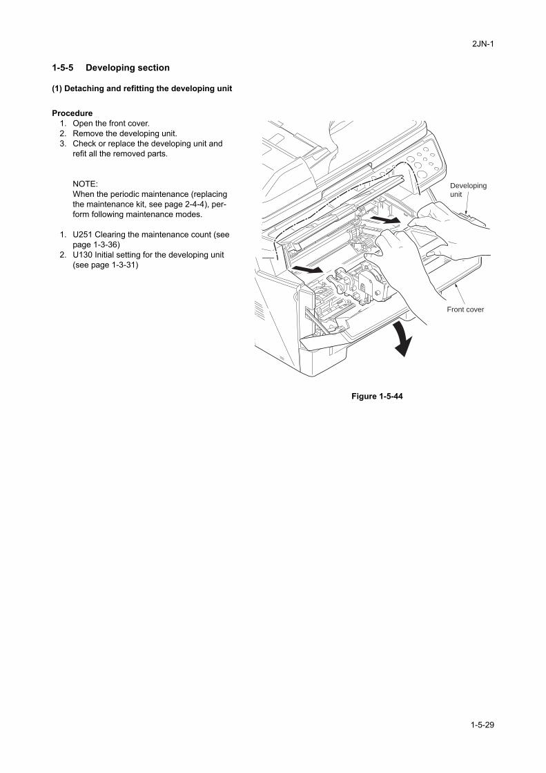
2JN-1
1-5-5 Developing section
(1) Detaching and refitting the developing unit
Procedure1. Open the front cover.2. Remove the developing unit.3. Check or replace the developing unit and
refit all the removed parts.
NOTE:When the periodic maintenance (replacing the maintenance kit, see page 2-4-4), per-form following maintenance modes.
1. U251 Clearing the maintenance count (see page 1-3-36)
2. U130 Initial setting for the developing unit (see page 1-3-31)
Figure 1-5-44
Developing
unit
Front cover
1-5-29
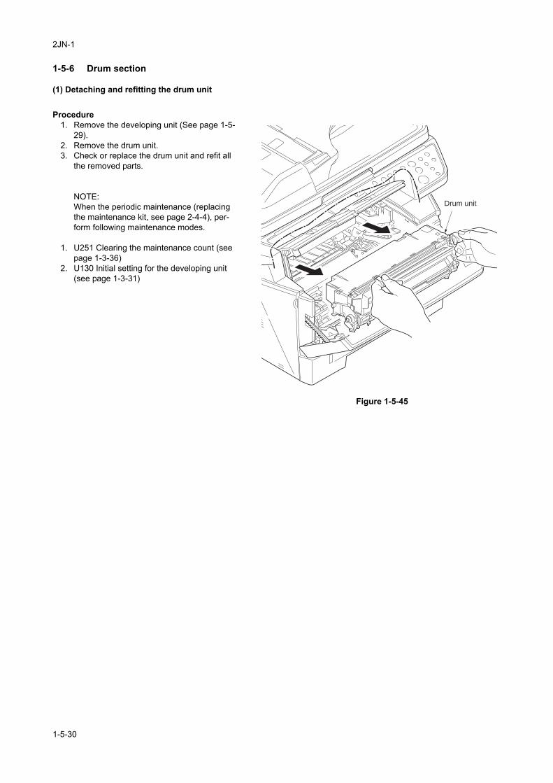
2JN-1
1-5-6 Drum section
(1) Detaching and refitting the drum unit
Procedure1. Remove the developing unit (See page 1-5-
29).2. Remove the drum unit.3. Check or replace the drum unit and refit all
the removed parts.
NOTE:When the periodic maintenance (replacing the maintenance kit, see page 2-4-4), per-form following maintenance modes.
1. U251 Clearing the maintenance count (see page 1-3-36)
2. U130 Initial setting for the developing unit (see page 1-3-31)
Figure 1-5-45
Drum unit
1-5-30
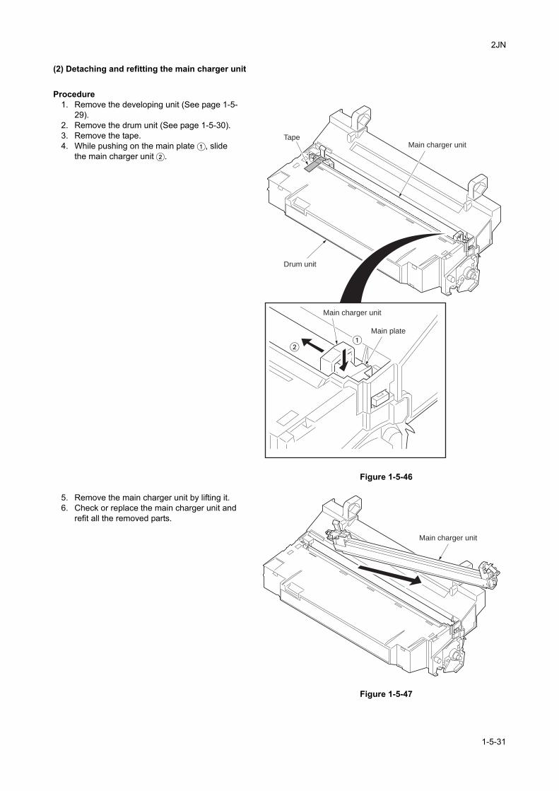
2JN
(2) Detaching and refitting the main charger unit
Procedure1. Remove the developing unit (See page 1-5-
29).2. Remove the drum unit (See page 1-5-30).3. Remove the tape.4. While pushing on the main plate �, slide
the main charger unit �.
Figure 1-5-46
5. Remove the main charger unit by lifting it.6. Check or replace the main charger unit and
refit all the removed parts.
Figure 1-5-47
Main charger unit
Main charger unit
Tape
Main plate
Drum unit
��
Main charger unit
1-5-31
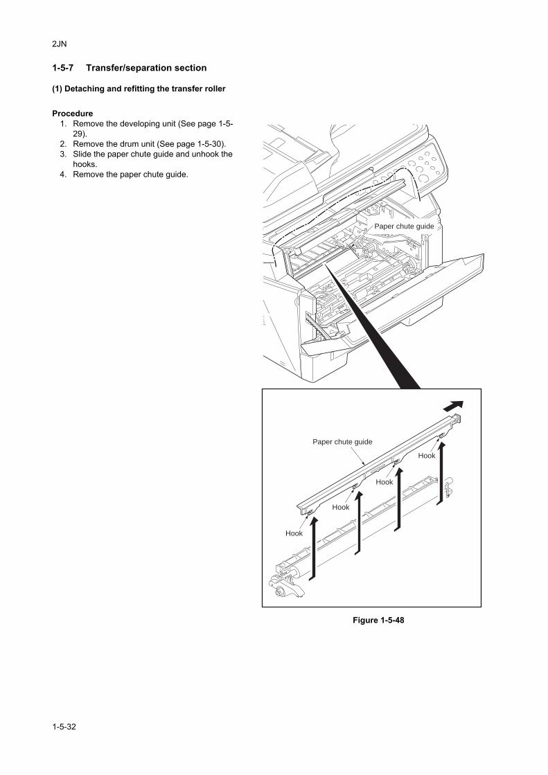
2JN
1-5-7 Transfer/separation section
(1) Detaching and refitting the transfer roller
Procedure1. Remove the developing unit (See page 1-5-
29).2. Remove the drum unit (See page 1-5-30).3. Slide the paper chute guide and unhook the
hooks.4. Remove the paper chute guide.
Figure 1-5-48
Paper chute guide
Paper chute guide
Hook
Hook
Hook
Hook
1-5-32
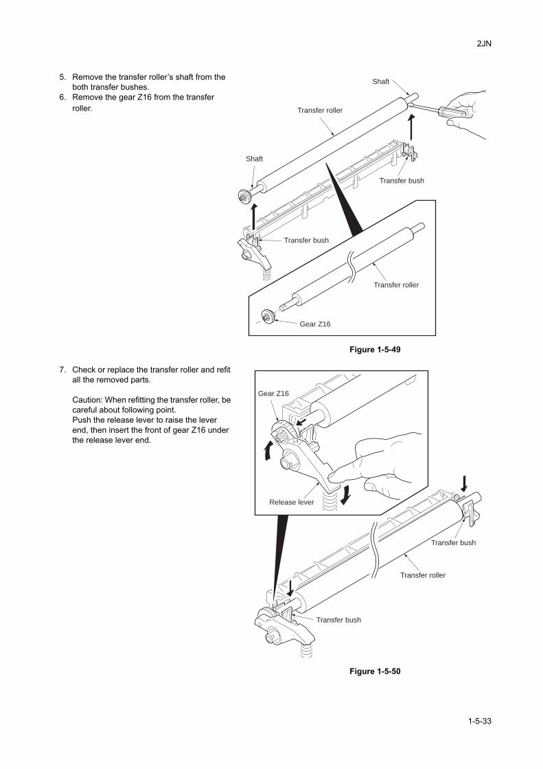
2JN
5. Remove the transfer roller’s shaft from the both transfer bushes.
6. Remove the gear Z16 from the transfer roller.
Figure 1-5-49
7. Check or replace the transfer roller and refit all the removed parts.
Caution: When refitting the transfer roller, be careful about following point.Push the release lever to raise the lever end, then insert the front of gear Z16 under the release lever end.
Figure 1-5-50
Transfer roller
Shaft
Shaft
Transfer roller
Transfer bush
Transfer bush
Gear Z16
Release lever
Gear Z16
Transfer bush
Transfer bush
Transfer roller
1-5-33
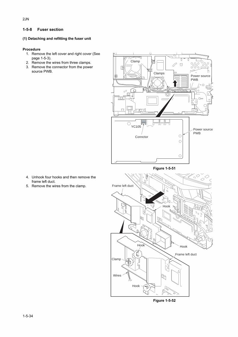
2JN
1-5-8 Fuser section
(1) Detaching and refitting the fuser unit
Procedure1. Remove the left cover and right cover (See
page 1-5-3).2. Remove the wires from three clamps.3. Remove the connector from the power
source PWB.
Figure 1-5-51
4. Unhook four hooks and then remove the frame left duct.
5. Remove the wires from the clamp.
Figure 1-5-52
YC105
Clamp
Clamps
Connctor
Power source
PWB
Power source
PWB
Frame left duct
Frame left duct
Hook
Clamp
Wires
Hook
Hook
Hook
1-5-34
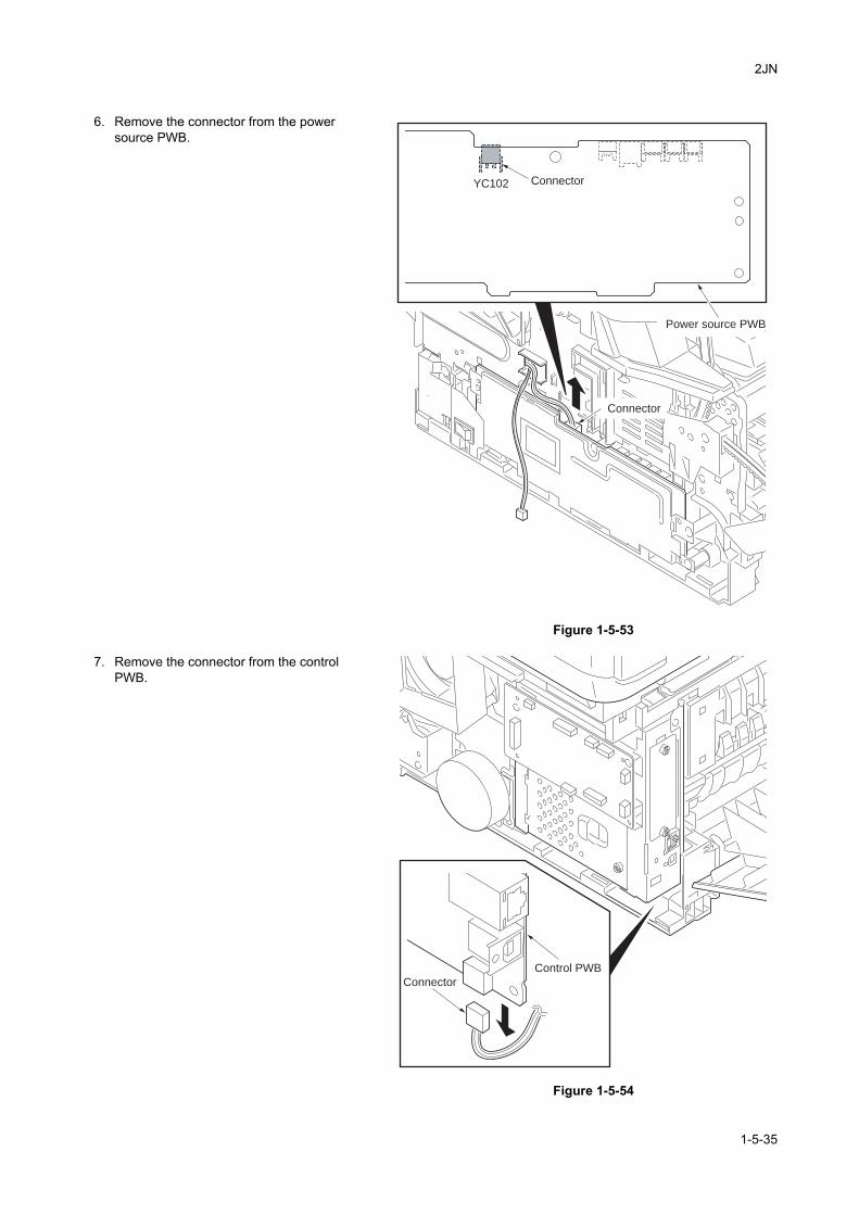
2JN
6. Remove the connector from the power source PWB.
Figure 1-5-53
7. Remove the connector from the control PWB.
Figure 1-5-54
YC102
Connector
Connector
Power source PWB
Connector
Control PWB
1-5-35
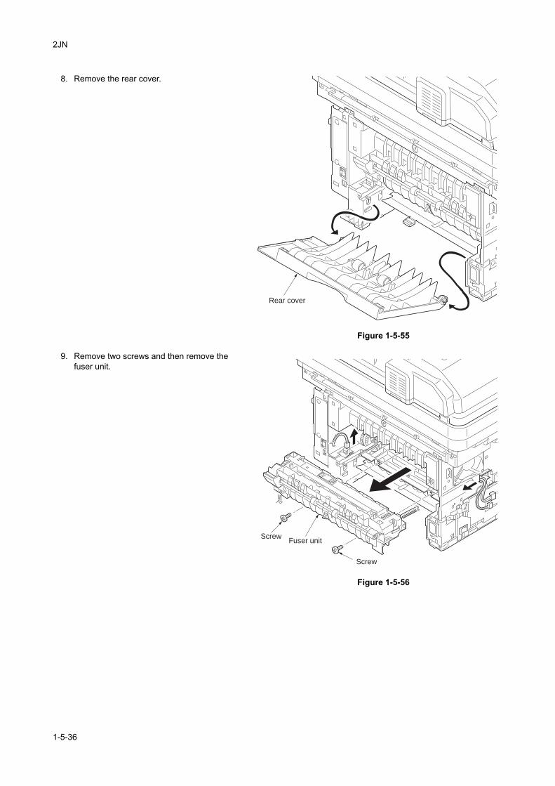
2JN
8. Remove the rear cover.
Figure 1-5-55
9. Remove two screws and then remove the fuser unit.
Figure 1-5-56
Rear cover
Fuser unit
Screw
Screw
1-5-36
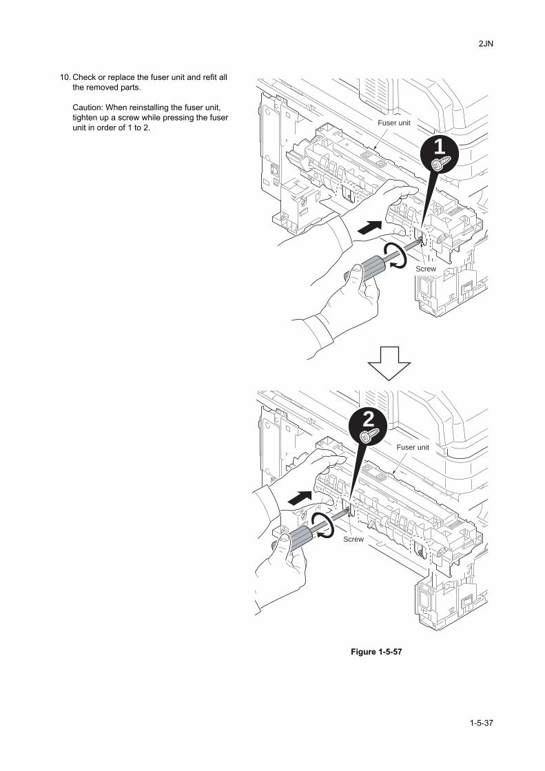
2JN
10. Check or replace the fuser unit and refit all the removed parts.
Caution: When reinstalling the fuser unit, tighten up a screw while pressing the fuser unit in order of 1 to 2.
Figure 1-5-57
1
2
Fuser unit
Screw
Screw
Fuser unit
1-5-37
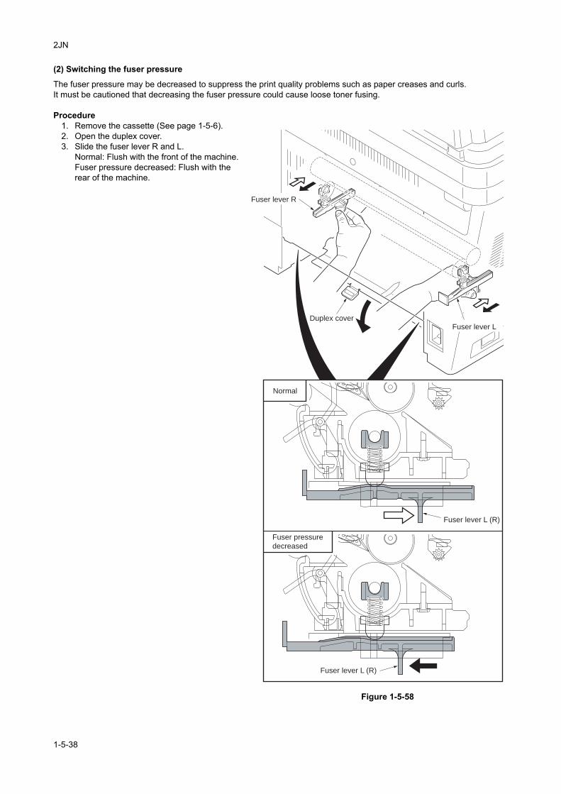
2JN
(2) Switching the fuser pressure
The fuser pressure may be decreased to suppress the print quality problems such as paper creases and curls.It must be cautioned that decreasing the fuser pressure could cause loose toner fusing.
Procedure1. Remove the cassette (See page 1-5-6).2. Open the duplex cover.3. Slide the fuser lever R and L.
Normal: Flush with the front of the machine.Fuser pressure decreased: Flush with the rear of the machine.
Figure 1-5-58
Fuser lever R
Duplex cover
Fuser lever L (R)
Fuser lever L (R)
Fuser lever L
Normal
Fuser pressure
decreased
1-5-38
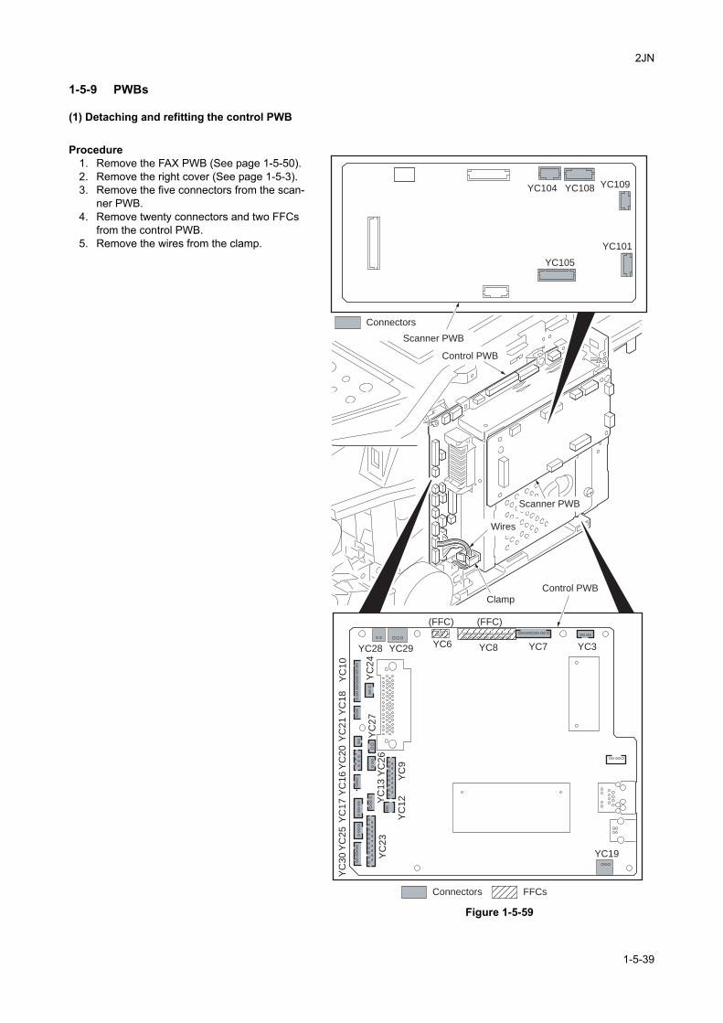
2JN
1-5-9 PWBs
(1) Detaching and refitting the control PWB
Procedure1. Remove the FAX PWB (See page 1-5-50).2. Remove the right cover (See page 1-5-3).3. Remove the five connectors from the scan-
ner PWB.4. Remove twenty connectors and two FFCs
from the control PWB.5. Remove the wires from the clamp.
Figure 1-5-59
Scanner PWB
Wires
Clamp
YC29YC28 YC6 YC8 YC7
(FFC)(FFC)
YC3
YC19
YC
30 Y
C23
YC
25
YC
17 Y
C13
YC
16
YC
20
YC
27
YC
21
YC
18
YC
24
YC
10
YC
26
YC
9Y
C12
YC101
YC109YC108YC104
YC105
Connectors
FFCsConnectors
Control PWB
Scanner PWB
Control PWB
1-5-39
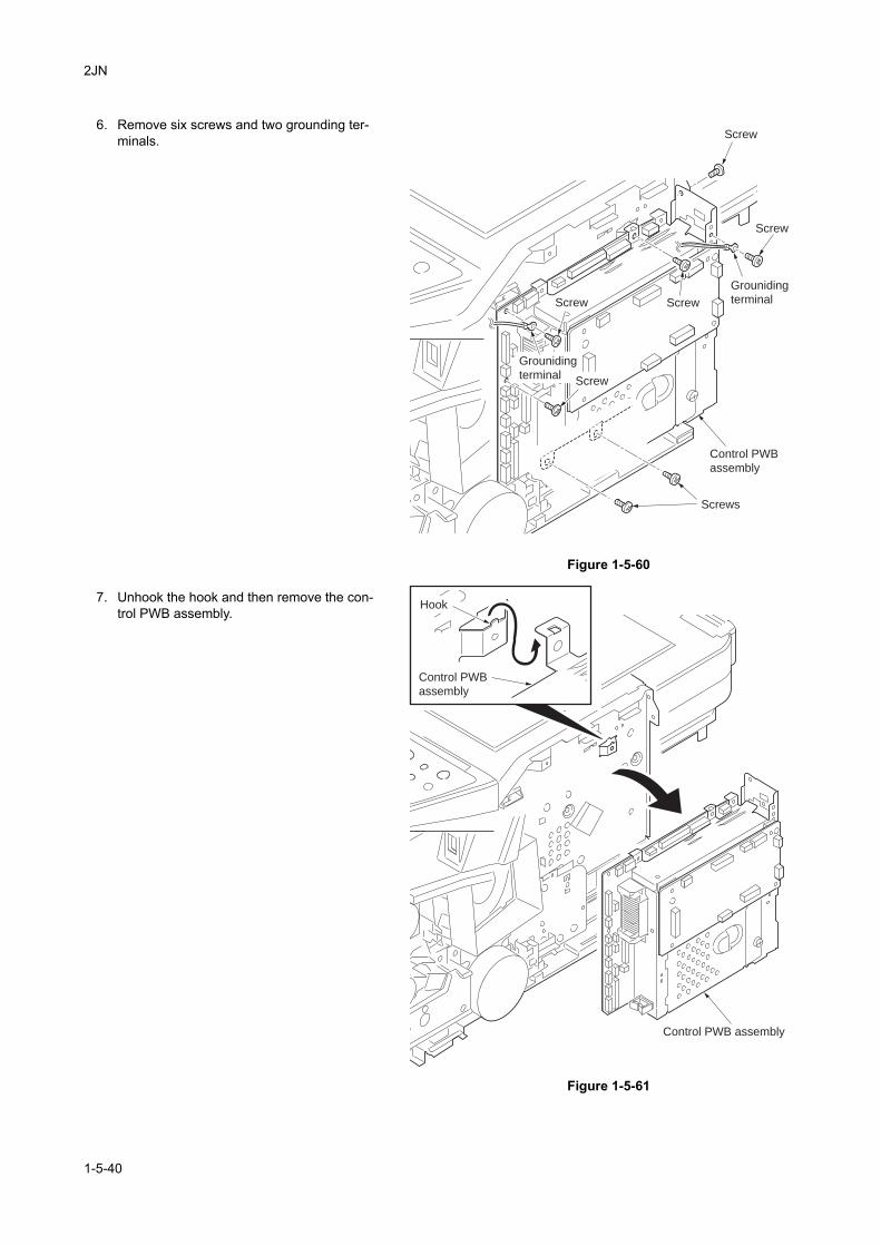
2JN
6. Remove six screws and two grounding ter-minals.
Figure 1-5-60
7. Unhook the hook and then remove the con-trol PWB assembly.
Figure 1-5-61
Control PWB
assembly
Screw
Screw
Screw Screw
Screws
Grouniding
terminal
Screw
Grouniding
terminal
Control PWB assembly
Control PWB
assembly
Hook
1-5-40
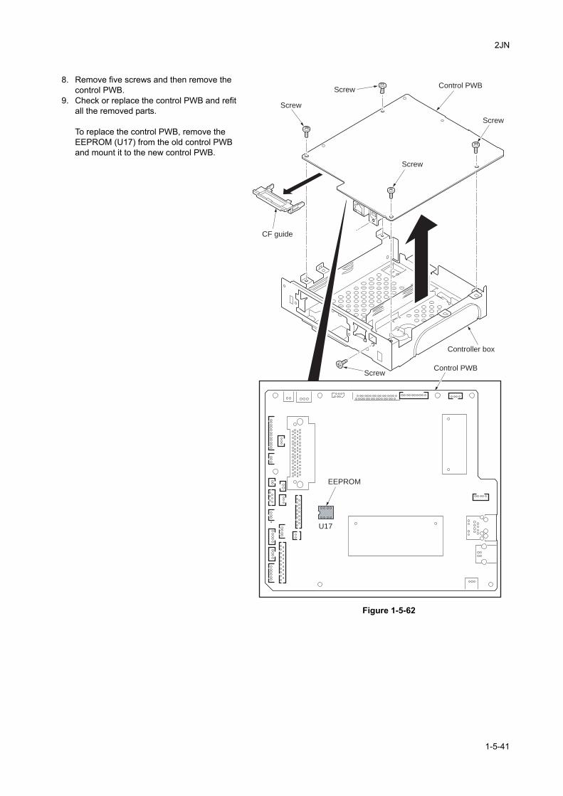
2JN
8. Remove five screws and then remove the control PWB.
9. Check or replace the control PWB and refit all the removed parts.
To replace the control PWB, remove the EEPROM (U17) from the old control PWB and mount it to the new control PWB.
Figure 1-5-62
Controller box
Screw
EEPROM
U17
Screw
ScrewControl PWB
Control PWB
Screw
Screw
CF guide
1-5-41
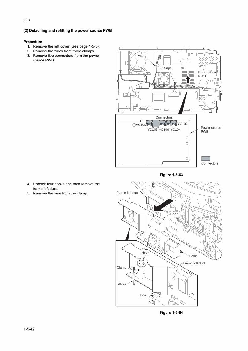
2JN
(2) Detaching and refitting the power source PWB
Procedure1. Remove the left cover (See page 1-5-3).2. Remove the wires from three clamps.3. Remove five connectors from the power
source PWB.
Figure 1-5-63
4. Unhook four hooks and then remove the frame left duct.
5. Remove the wire from the clamp.
Figure 1-5-64
YC107
YC104YC106YC108
YC105
Clamp
Clamps
Connectors
Power source
PWB
Connectors
Power source
PWB
Frame left duct
Frame left duct
HookHook
Hook
Clamp
Wires
Hook
1-5-42
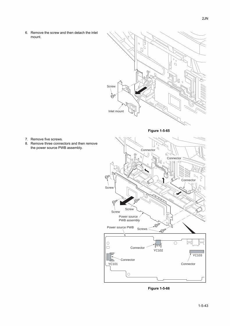
2JN
6. Remove the screw and then detach the inlet mount.
Figure 1-5-65
7. Remove five screws.8. Remove three connectors and then remove
the power source PWB assembly.
Figure 1-5-66
Inlet mount
Screw
YC103
YC102
YC101
Power source PWB
Power source
PWB assembly
Connector
Connector
Connector
Screw
Screw
Screw
Screws
Connector
Connector
Connector
1-5-43
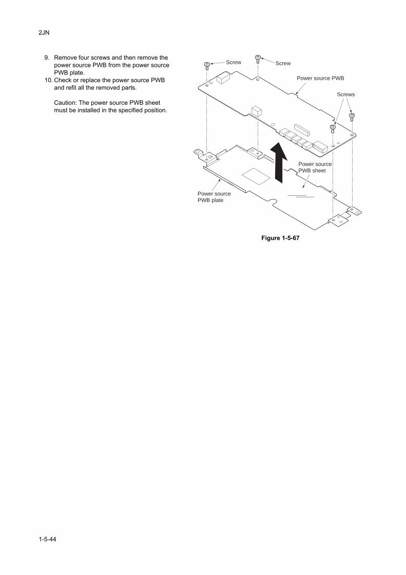
2JN
9. Remove four screws and then remove the power source PWB from the power source PWB plate.
10. Check or replace the power source PWB and refit all the removed parts.
Caution: The power source PWB sheet must be installed in the specified position.
Figure 1-5-67
Screws
Screw
Power source PWB
Power source
PWB plate
Power source
PWB sheet
Screw
1-5-44
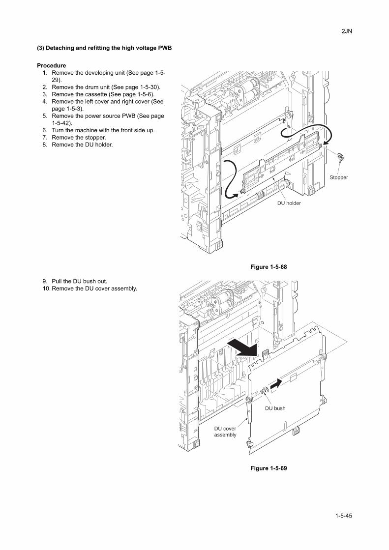
2JN
(3) Detaching and refitting the high voltage PWB
Procedure1. Remove the developing unit (See page 1-5-
29).2. Remove the drum unit (See page 1-5-30).3. Remove the cassette (See page 1-5-6).4. Remove the left cover and right cover (See
page 1-5-3).5. Remove the power source PWB (See page
1-5-42).6. Turn the machine with the front side up.7. Remove the stopper.8. Remove the DU holder.
Figure 1-5-68
9. Pull the DU bush out.10. Remove the DU cover assembly.
Figure 1-5-69
DU holder
Stopper
DU bush
DU cover
assembly
1-5-45
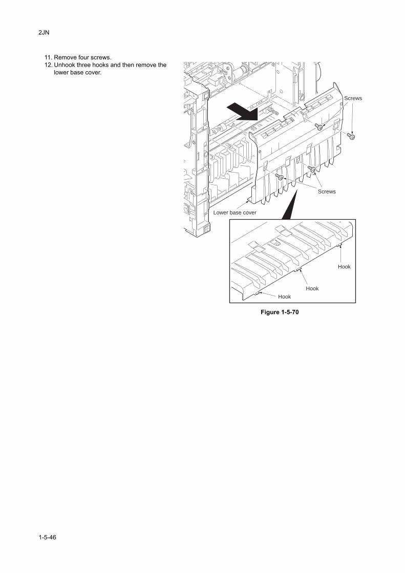
2JN
11. Remove four screws.12. Unhook three hooks and then remove the
lower base cover.
Figure 1-5-70
Screws
Screws
Hook
Hook
Hook
Lower base cover
1-5-46
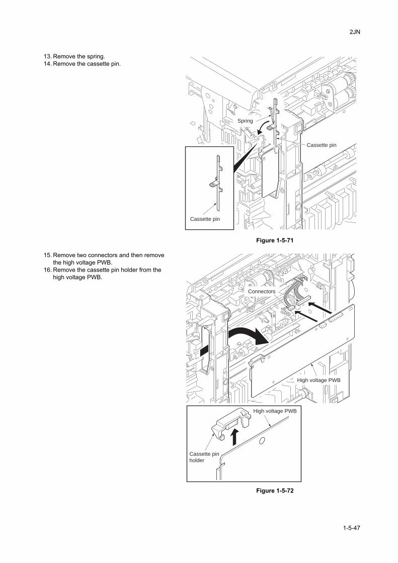
2JN
13. Remove the spring.14. Remove the cassette pin.
Figure 1-5-71
15. Remove two connectors and then remove the high voltage PWB.
16. Remove the cassette pin holder from the high voltage PWB.
Figure 1-5-72
Spring
Cassette pin
Cassette pin
Cassette pin
holder
High voltage PWB
High voltage PWB
Connectors
1-5-47
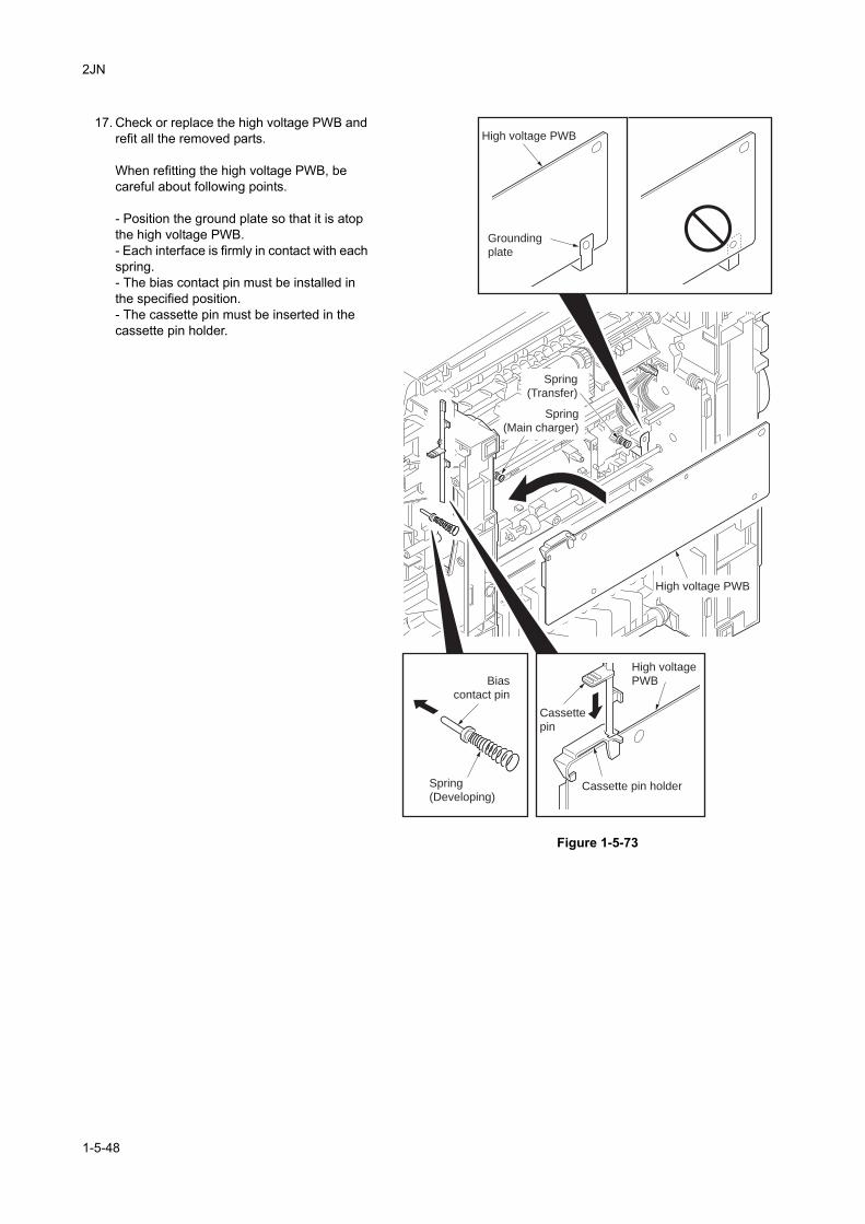
2JN
17. Check or replace the high voltage PWB and refit all the removed parts.
When refitting the high voltage PWB, be careful about following points.
- Position the ground plate so that it is atop the high voltage PWB.- Each interface is firmly in contact with each spring.- The bias contact pin must be installed in the specified position.- The cassette pin must be inserted in the cassette pin holder.
Figure 1-5-73
Cassette
pin
Cassette pin holder
High voltage PWB
High voltage
PWB
High voltage PWB
Grounding
plate
Bias
contact pin
Spring
(Main charger)
Spring
(Developing)
Spring
(Transfer)
1-5-48
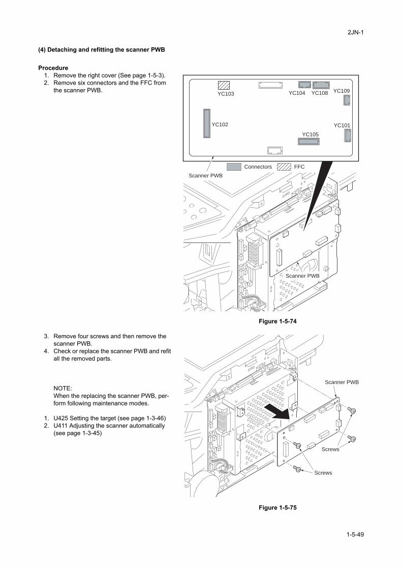
2JN-1
(4) Detaching and refitting the scanner PWB
Procedure1. Remove the right cover (See page 1-5-3).2. Remove six connectors and the FFC from
the scanner PWB.
Figure 1-5-74
3. Remove four screws and then remove the scanner PWB.
4. Check or replace the scanner PWB and refit all the removed parts.
NOTE:When the replacing the scanner PWB, per-form following maintenance modes.
1. U425 Setting the target (see page 1-3-46)2. U411 Adjusting the scanner automatically
(see page 1-3-45)
Figure 1-5-75
YC102
YC103
FFCConnectors
Scanner PWB
Scanner PWB
YC101
YC109YC108YC104
YC105
Scanner PWB
Screws
Screws
1-5-49
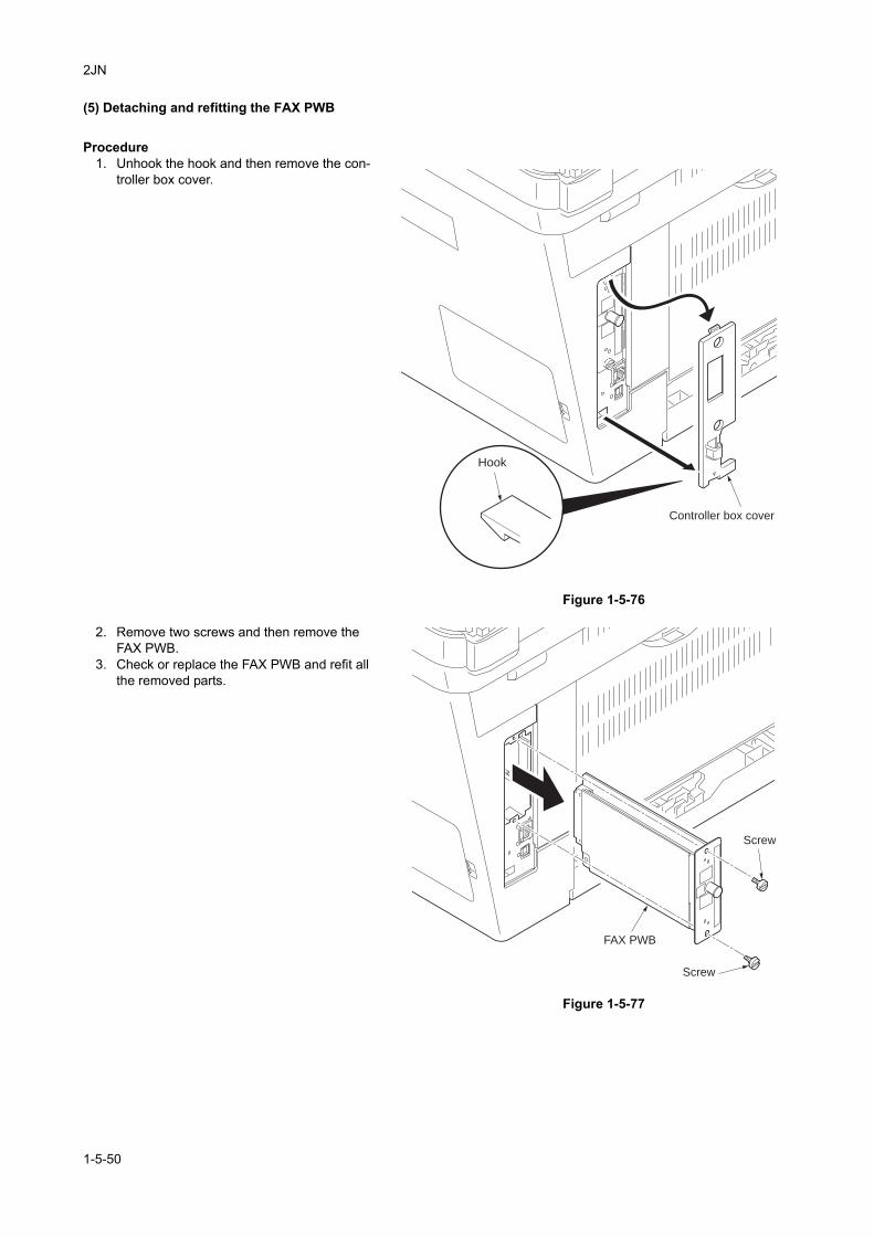
2JN
(5) Detaching and refitting the FAX PWB
Procedure1. Unhook the hook and then remove the con-
troller box cover.
Figure 1-5-76
2. Remove two screws and then remove the FAX PWB.
3. Check or replace the FAX PWB and refit all the removed parts.
Figure 1-5-77
Controller box cover
Hook
FAX PWB
Screw
Screw
1-5-50
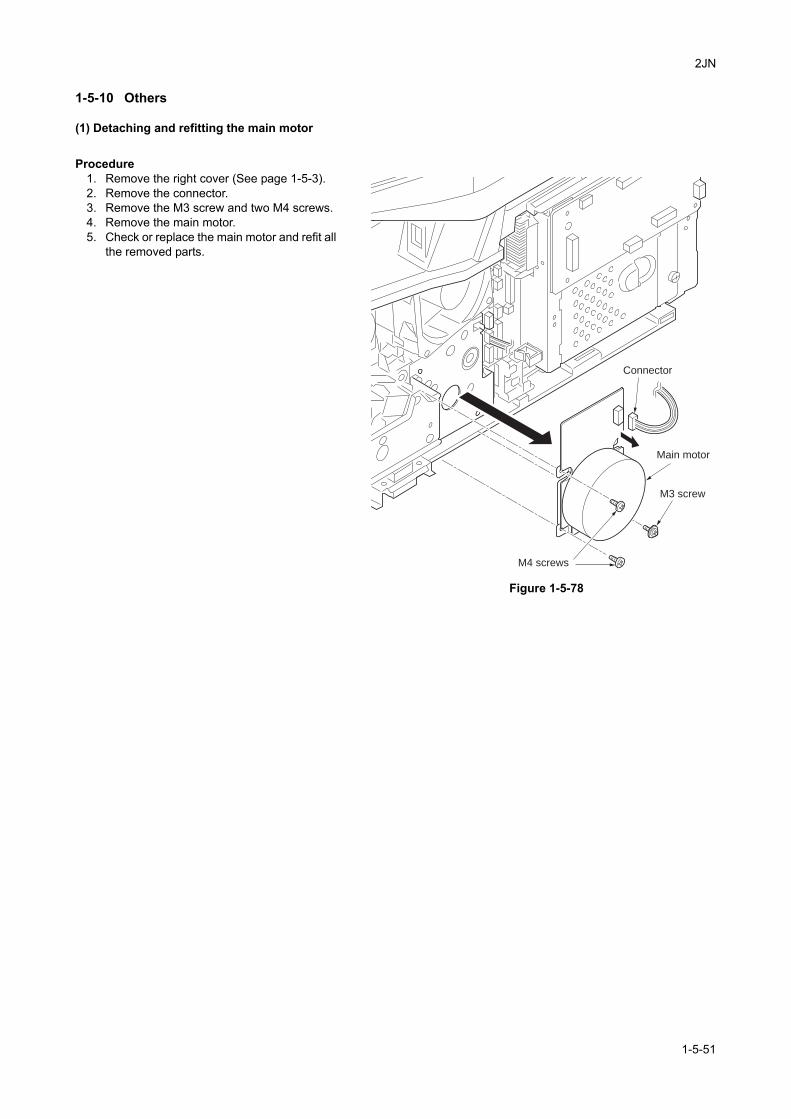
2JN
1-5-10 Others
(1) Detaching and refitting the main motor
Procedure1. Remove the right cover (See page 1-5-3).2. Remove the connector.3. Remove the M3 screw and two M4 screws.4. Remove the main motor.5. Check or replace the main motor and refit all
the removed parts.
Figure 1-5-78
Main motor
Connector
M3 screw
M4 screws
1-5-51
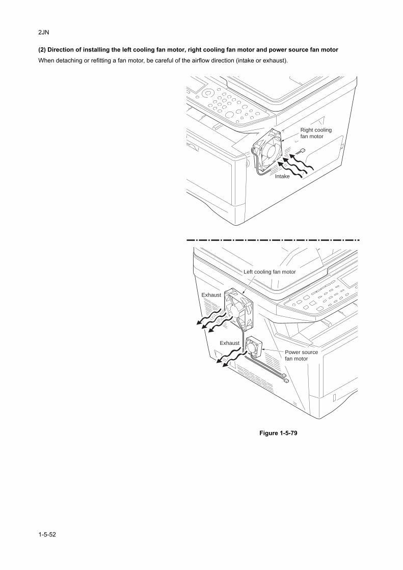
2JN
(2) Direction of installing the left cooling fan motor, right cooling fan motor and power source fan motor
When detaching or refitting a fan motor, be careful of the airflow direction (intake or exhaust).
Figure 1-5-79
Power source
fan motor
Right cooling
fan motor
Exhaust
Exhaust
Intake
Left cooling fan motor
1-5-52

2JN
1-5-11 DPRefer to the DP’s service manual.
1-5-53

2JN
This page is intentionally left blank.
1-5-54
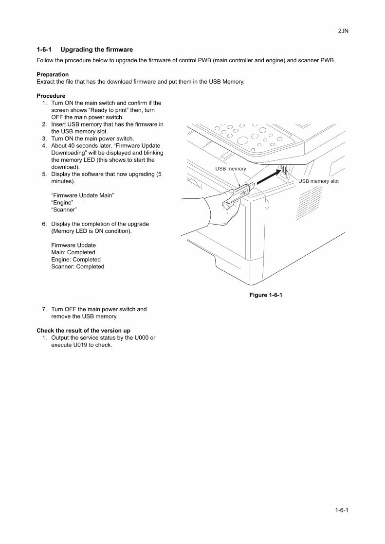
2JN
1-6 Requirements on PWB Replacement
1-6-1 Upgrading the firmwareFollow the procedure below to upgrade the firmware of control PWB (main controller and engine) and scanner PWB.
PreparationExtract the file that has the download firmware and put them in the USB Memory.
Procedure1. Turn ON the main switch and confirm if the
screen shows “Ready to print” then, turn OFF the main power switch.
2. Insert USB memory that has the firmware in the USB memory slot.
3. Turn ON the main power switch.4. About 40 seconds later, “Firmware Update
Downloading” will be displayed and blinking the memory LED (this shows to start the download).
5. Display the software that now upgrading (5 minutes).
“Firmware Update Main”“Engine”“Scanner”
6. Display the completion of the upgrade (Memory LED is ON condition).
Firmware UpdateMain: CompletedEngine: CompletedScanner: Completed
Figure 1-6-1
7. Turn OFF the main power switch and remove the USB memory.
Check the result of the version up1. Output the service status by the U000 or
execute U019 to check.
USB memory
USB memory slot
1-6-1
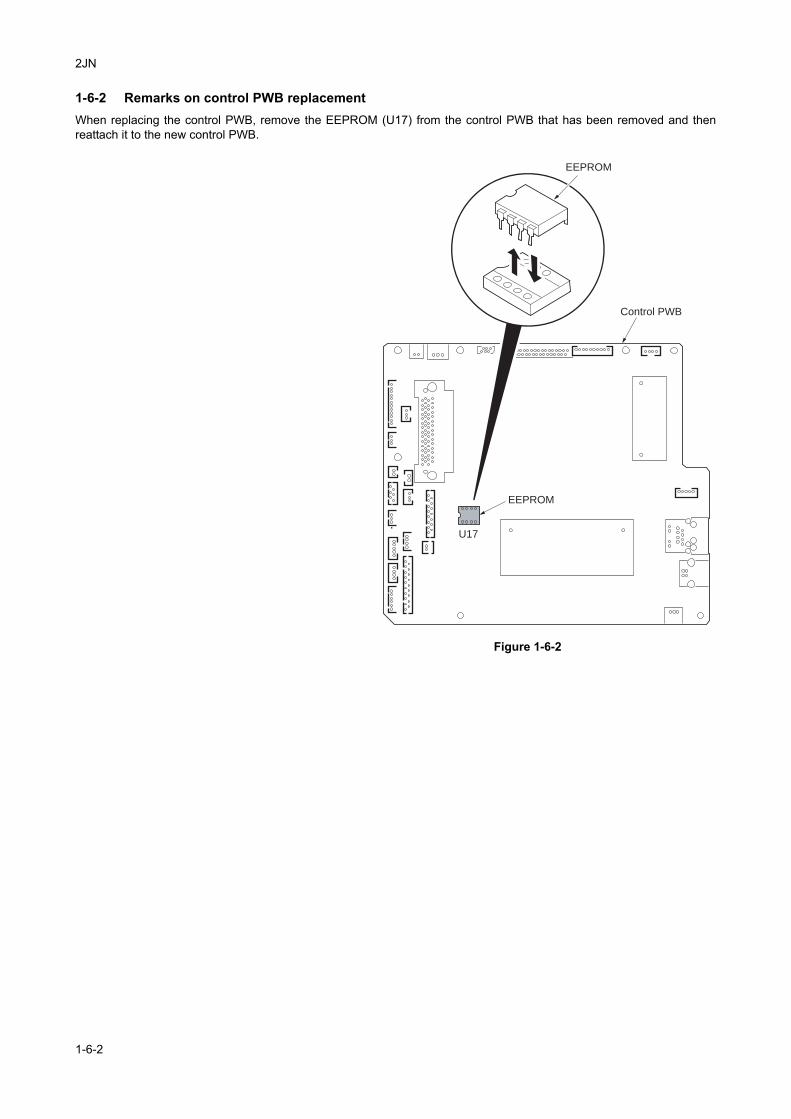
2JN
1-6-2 Remarks on control PWB replacementWhen replacing the control PWB, remove the EEPROM (U17) from the control PWB that has been removed and thenreattach it to the new control PWB.
Figure 1-6-2
EEPROM
U17
Control PWB
EEPROM
1-6-2
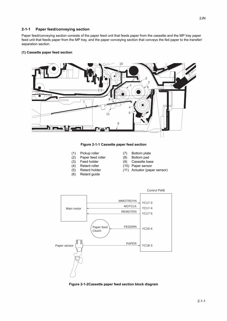
2JN
2-1 Mechanical Construction
2-1-1 Paper feed/conveying sectionPaper feed/conveying section consists of the paper feed unit that feeds paper from the cassette and the MP tray paper feed unit that feeds paper from the MP tray, and the paper conveying section that conveys the fed paper to the transfer/separation section.
(1) Cassette paper feed section
Figure 2-1-1 Cassette paper feed section
Figure 2-1-2Cassette paper feed section block diagram
1
9
7
3
4
5
2
6
8
10
11
(1) Pickup roller(2) Paper feed roller(3) Feed holder(4) Retard roller(5) Retard holder(6) Retard guide
(7) Bottom plate(8) Bottom pad(9) Cassette base(10) Paper sensor(11) Actuator (paper sensor)
FEDDRN
MMOTRDYN
YC18-3Paper sensor
Paper feed
Clutch
Main motor
Control PWB
PAPER
MOTCLK
REMOTEN
YC20-4
YC17-3
YC17-4
YC17-5
2-1-1
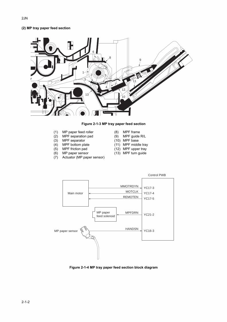
2JN
(2) MP tray paper feed section
Figure 2-1-3 MP tray paper feed section
Figure 2-1-4 MP tray paper feed section block diagram
12
6
8
5
9
47
10
11
12
3
13
(1) MP paper feed roller(2) MPF separation pad(3) MPF separator(4) MPF bottom plate(5) MPF friction pad(6) MP paper sensor(7) Actuator (MP paper sensor)
(8) MPF frame(9) MPF guide R/L(10) MPF base(11) MPF middle tray(12) MPF upper tray(13) MPF turn guide
MMOTRDYN
YC16-3
MPFDRN
MP paper sensor
MP paper
feed solenoid
Main motor
Control PWB
HANDSN
YC21-2
MOTCLK
REMOTEN
YC17-3
YC17-4
YC17-5
2-1-2
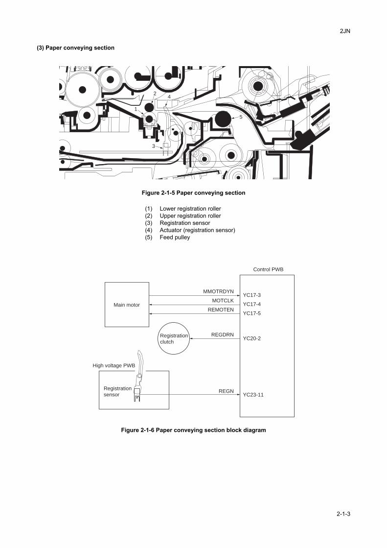
2JN
(3) Paper conveying section
Figure 2-1-5 Paper conveying section
Figure 2-1-6 Paper conveying section block diagram
1
4
3
5
2
(1) Lower registration roller(2) Upper registration roller(3) Registration sensor(4) Actuator (registration sensor)(5) Feed pulley
MMOTRDYN
REGDRNRegistration
clutch
Main motor
Control PWB
YC23-11
Registration
sensor
High voltage PWB
REGN
YC20-2
MOTCLK
REMOTEN
YC17-3
YC17-4
YC17-5
2-1-3
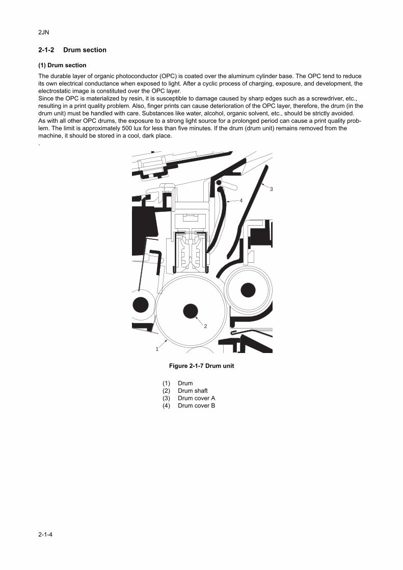
2JN
2-1-2 Drum section
(1) Drum section
The durable layer of organic photoconductor (OPC) is coated over the aluminum cylinder base. The OPC tend to reduce its own electrical conductance when exposed to light. After a cyclic process of charging, exposure, and development, the electrostatic image is constituted over the OPC layer.Since the OPC is materialized by resin, it is susceptible to damage caused by sharp edges such as a screwdriver, etc., resulting in a print quality problem. Also, finger prints can cause deterioration of the OPC layer, therefore, the drum (in the drum unit) must be handled with care. Substances like water, alcohol, organic solvent, etc., should be strictly avoided. As with all other OPC drums, the exposure to a strong light source for a prolonged period can cause a print quality prob-lem. The limit is approximately 500 lux for less than five minutes. If the drum (drum unit) remains removed from the machine, it should be stored in a cool, dark place..
Figure 2-1-7 Drum unit
1
2
3
4
(1) Drum(2) Drum shaft(3) Drum cover A(4) Drum cover B
2-1-4
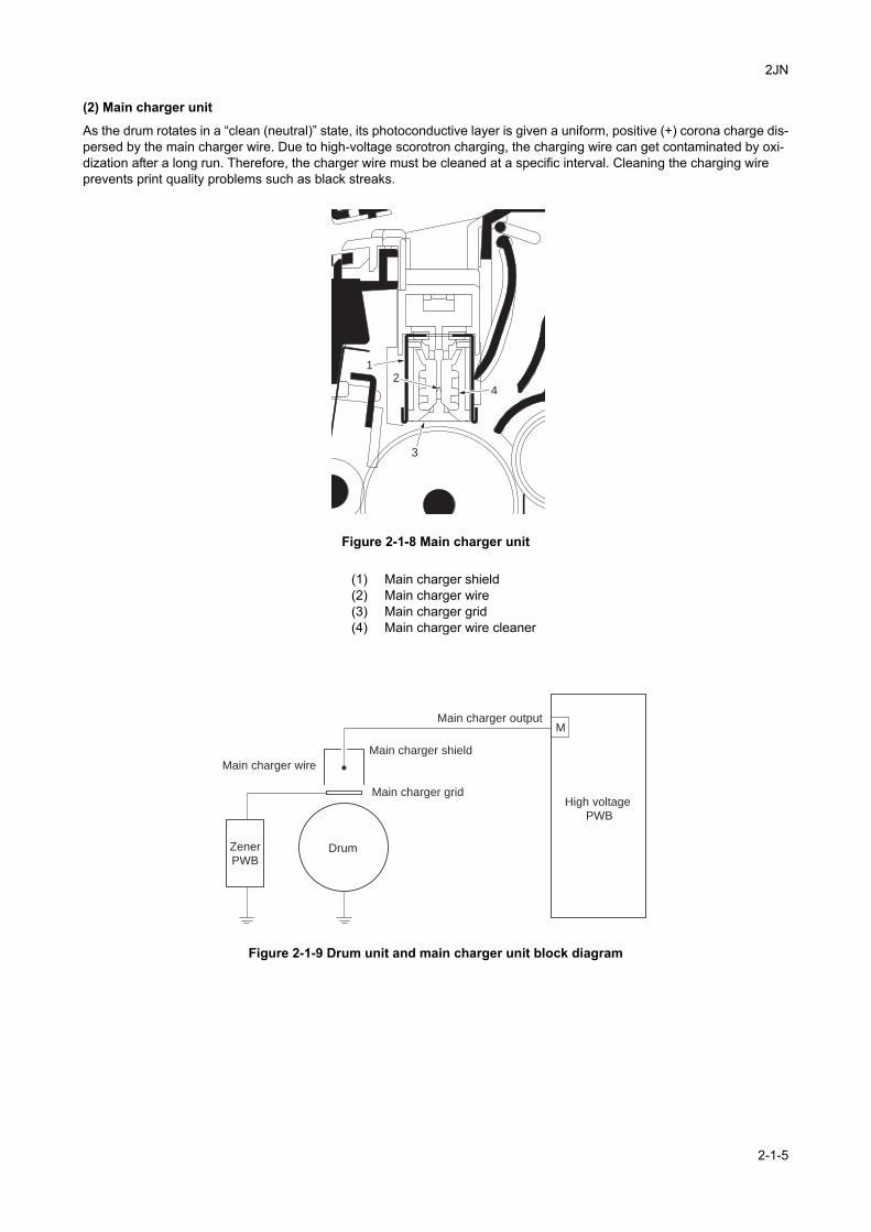
2JN
(2) Main charger unit
As the drum rotates in a “clean (neutral)” state, its photoconductive layer is given a uniform, positive (+) corona charge dis-persed by the main charger wire. Due to high-voltage scorotron charging, the charging wire can get contaminated by oxi-dization after a long run. Therefore, the charger wire must be cleaned at a specific interval. Cleaning the charging wire prevents print quality problems such as black streaks.
Figure 2-1-8 Main charger unit
Figure 2-1-9 Drum unit and main charger unit block diagram
1
42
3
(1) Main charger shield(2) Main charger wire(3) Main charger grid(4) Main charger wire cleaner
Main charger wire
Main charger shield
Main charger grid
Drum
High voltage
PWB
Main charger output
Zener
PWB
M
2-1-5
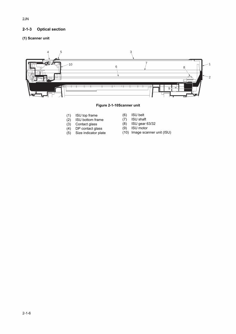
2JN
2-1-3 Optical section
(1) Scanner unit
Figure 2-1-10Scanner unit
1
3
7
8
9
5
10
4
6
2
(1) ISU top frame(2) ISU bottom frame(3) Contact glass(4) DP contact glass(5) Size indicator plate
(6) ISU belt(7) ISU shaft(8) ISU gear 63/32(9) ISU motor(10) Image scanner unit (ISU)
2-1-6
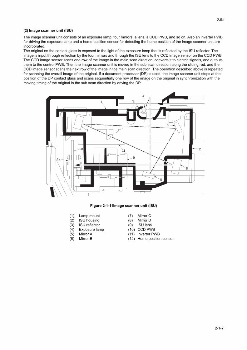
2JN
(2) Image scanner unit (ISU)
The image scanner unit consists of an exposure lamp, four mirrors, a lens, a CCD PWB, and so on. Also an inverter PWB for driving the exposure lamp and a home position sensor for detecting the home position of the image scanner unit are incorporated.The original on the contact glass is exposed to the light of the exposure lamp that is reflected by the ISU reflector. The image is input through reflection by the four mirrors and through the ISU lens to the CCD image sensor on the CCD PWB. The CCD image sensor scans one row of the image in the main scan direction, converts it to electric signals, and outputs them to the control PWB. Then the image scanner unit is moved in the sub scan direction along the sliding rod, and the CCD image sensor scans the next row of the image in the main scan direction. The operation described above is repeated for scanning the overall image of the original. If a document processor (DP) is used, the image scanner unit stops at the position of the DP contact glass and scans sequentially one row of the image on the original in synchronization with the moving timing of the original in the sub scan direction by driving the DP.
Figure 2-1-11Image scanner unit (ISU)
1 3
4
2
5
9
1011
12
6
7
8
(1) Lamp mount(2) ISU housing(3) ISU reflector(4) Exposure lamp(5) Mirror A(6) Mirror B
(7) Mirror C(8) Mirror D(9) ISU lens(10) CCD PWB(11) Inverter PWB(12) Home position sensor
2-1-7
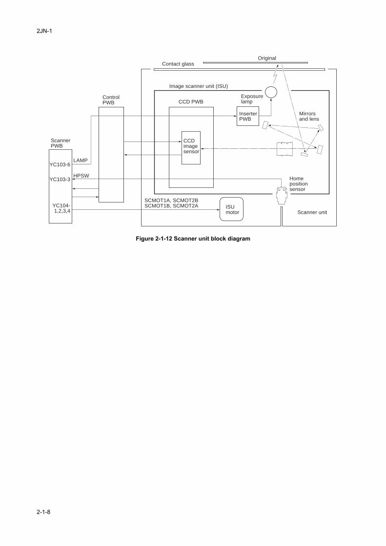
2JN-1
Figure 2-1-12 Scanner unit block diagram
CCDimagesensor
ControlPWB
ScannerPWB
CCD PWB
HPSW
LAMP
SCMOT1A, SCMOT2BSCMOT1B, SCMOT2A
Exposurelamp
InserterPWB
ISUmotor
Homepositionsensor
Scanner unit
Mirrorsand lens
Image scanner unit (ISU)
OriginalContact glass
YC103-6
YC103-3
YC104-1,2,3,4
2-1-8
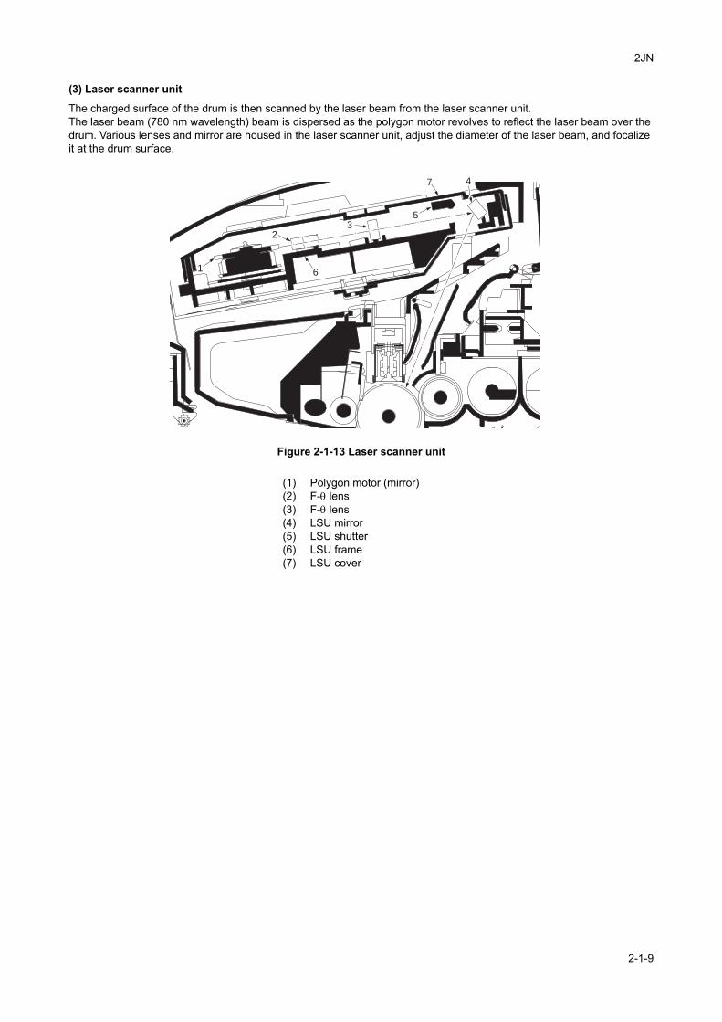
2JN
(3) Laser scanner unit
The charged surface of the drum is then scanned by the laser beam from the laser scanner unit.The laser beam (780 nm wavelength) beam is dispersed as the polygon motor revolves to reflect the laser beam over the drum. Various lenses and mirror are housed in the laser scanner unit, adjust the diameter of the laser beam, and focalize it at the drum surface.
Figure 2-1-13 Laser scanner unit
1
23
4
5
7
6
(1) Polygon motor (mirror)(2) F-θ lens(3) F-θ lens(4) LSU mirror(5) LSU shutter(6) LSU frame(7) LSU cover
2-1-9
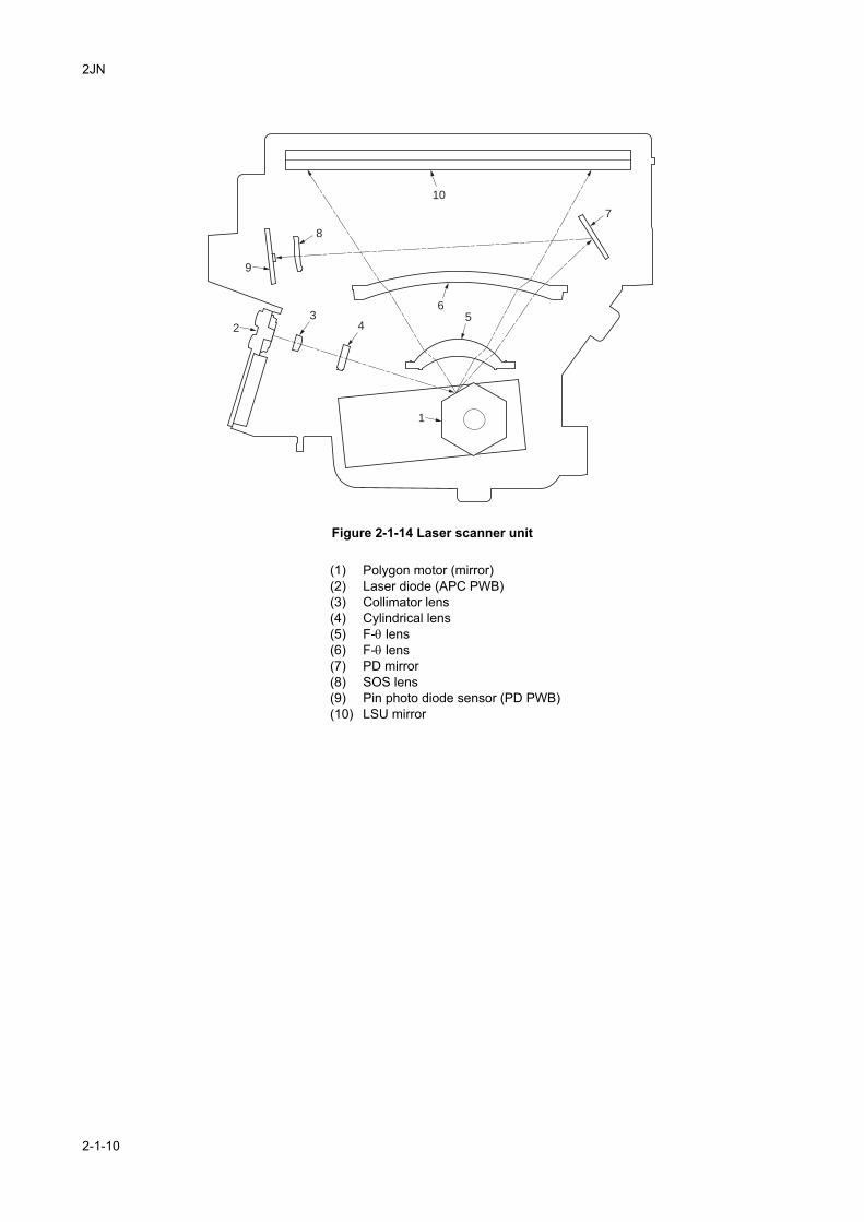
2JN
Figure 2-1-14 Laser scanner unit
1
23
8
9
10
45
6
7
(1) Polygon motor (mirror)(2) Laser diode (APC PWB)(3) Collimator lens(4) Cylindrical lens(5) F-θ lens(6) F-θ lens(7) PD mirror(8) SOS lens(9) Pin photo diode sensor (PD PWB)(10) LSU mirror
2-1-10
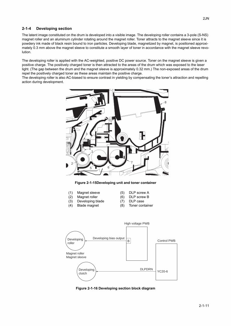
2JN
2-1-4 Developing sectionThe latent image constituted on the drum is developed into a visible image. The developing roller contains a 3-pole (S-NS) magnet roller and an aluminum cylinder rotating around the magnet roller. Toner attracts to the magnet sleeve since it is powdery ink made of black resin bound to iron particles. Developing blade, magnetized by magnet, is positioned approxi-mately 0.3 mm above the magnet sleeve to constitute a smooth layer of toner in accordance with the magnet sleeve revo-lution.
The developing roller is applied with the AC-weighted, positive DC power source. Toner on the magnet sleeve is given a positive charge. The positively charged toner is then attracted to the areas of the drum which was exposed to the laser light. (The gap between the drum and the magnet sleeve is approximately 0.32 mm.) The non-exposed areas of the drum repel the positively charged toner as these areas maintain the positive charge.The developing roller is also AC-biased to ensure contrast in yielding by compensating the toner’s attraction and repelling action during development.
Figure 2-1-15Developing unit and toner container
Figure 2-1-16 Developing section block diagram
1
3
4
6
7
8
5
2
(1) Magnet sleeve(2) Magnet roller(3) Developing blade(4) Blade magnet
(5) DLP screw A(6) DLP screw B(7) DLP case(8) Toner container
DLPDRNDeveloping
clutchYC20-6
BDeveloping
roller
Magnet roller
Magnet sleeve
Developing bias output
High voltage PWB
Control PWB
2-1-11
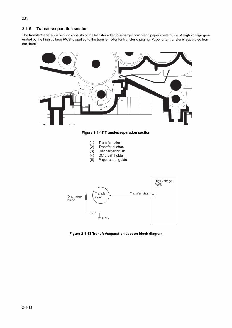
2JN
2-1-5 Transfer/separation sectionThe transfer/separation section consists of the transfer roller, discharger brush and paper chute guide. A high voltage gen-erated by the high voltage PWB is applied to the transfer roller for transfer charging. Paper after transfer is separated from the drum.
Figure 2-1-17 Transfer/separation section
Figure 2-1-18 Transfer/separation section block diagram
1
2
3
4
5
(1) Transfer roller(2) Transfer bushes(3) Discharger brush(4) DC brush holder(5) Paper chute guide
TTransfer
roller
GND
High voltage
PWB
Transfer biasDischarger
brush
2-1-12
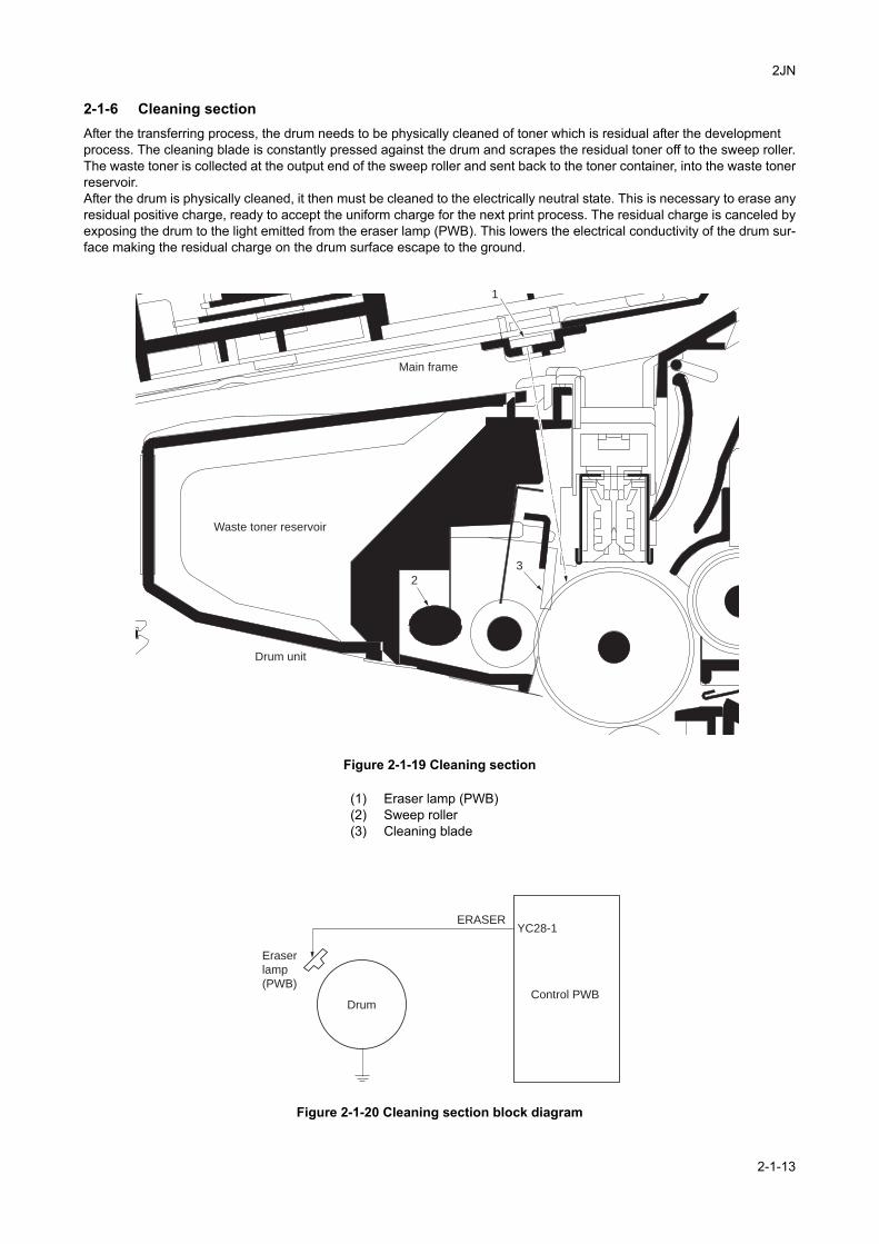
2JN
2-1-6 Cleaning sectionAfter the transferring process, the drum needs to be physically cleaned of toner which is residual after the developmentprocess. The cleaning blade is constantly pressed against the drum and scrapes the residual toner off to the sweep roller.The waste toner is collected at the output end of the sweep roller and sent back to the toner container, into the waste tonerreservoir.After the drum is physically cleaned, it then must be cleaned to the electrically neutral state. This is necessary to erase anyresidual positive charge, ready to accept the uniform charge for the next print process. The residual charge is canceled byexposing the drum to the light emitted from the eraser lamp (PWB). This lowers the electrical conductivity of the drum sur-face making the residual charge on the drum surface escape to the ground.
Figure 2-1-19 Cleaning section
Figure 2-1-20 Cleaning section block diagram
1
3
2
Main frame
Waste toner reservoir
Drum unit
(1) Eraser lamp (PWB)(2) Sweep roller(3) Cleaning blade
ERASERYC28-1
Drum
Eraser
lamp
(PWB)Control PWB
2-1-13
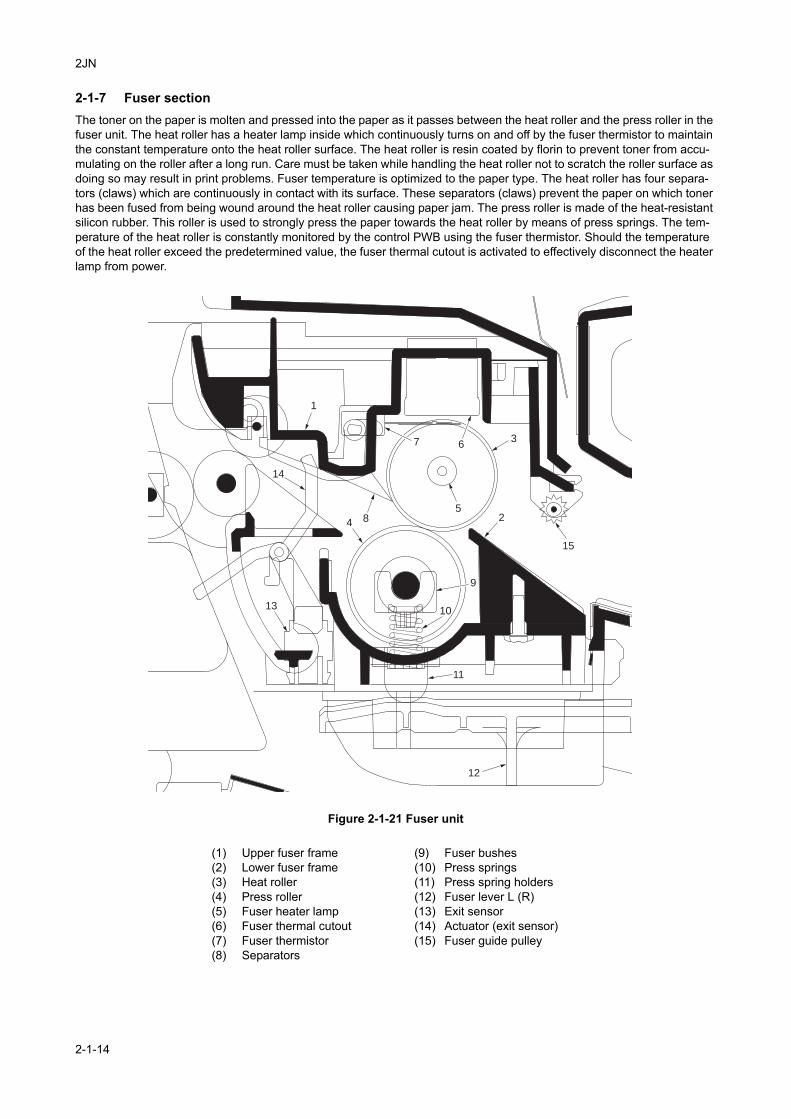
2JN
2-1-7 Fuser sectionThe toner on the paper is molten and pressed into the paper as it passes between the heat roller and the press roller in the fuser unit. The heat roller has a heater lamp inside which continuously turns on and off by the fuser thermistor to maintain the constant temperature onto the heat roller surface. The heat roller is resin coated by florin to prevent toner from accu-mulating on the roller after a long run. Care must be taken while handling the heat roller not to scratch the roller surface as doing so may result in print problems. Fuser temperature is optimized to the paper type. The heat roller has four separa-tors (claws) which are continuously in contact with its surface. These separators (claws) prevent the paper on which toner has been fused from being wound around the heat roller causing paper jam. The press roller is made of the heat-resistant silicon rubber. This roller is used to strongly press the paper towards the heat roller by means of press springs. The tem-perature of the heat roller is constantly monitored by the control PWB using the fuser thermistor. Should the temperature of the heat roller exceed the predetermined value, the fuser thermal cutout is activated to effectively disconnect the heater lamp from power.
Figure 2-1-21 Fuser unit
1
2
9
10
11
12
367
4
14
15
13
85
(1) Upper fuser frame(2) Lower fuser frame(3) Heat roller(4) Press roller(5) Fuser heater lamp(6) Fuser thermal cutout(7) Fuser thermistor(8) Separators
(9) Fuser bushes(10) Press springs(11) Press spring holders(12) Fuser lever L (R)(13) Exit sensor(14) Actuator (exit sensor)(15) Fuser guide pulley
2-1-14
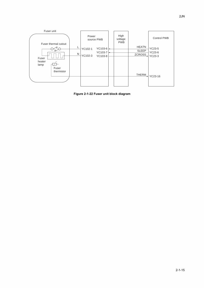
2JN
Figure 2-1-22 Fuser unit block diagram
N
L
THERM
HEATN
SLEEP
ZCROSS
YC102-1
YC102-3
YC103-6
YC103-7
YC103-8
YC23-5
YC23-6
YC23-3
YC23-16
Fuser unit
Fuser
thermistor
Fuser
heater
lamp
Fuser thermal cutout
Power
source PWBControl PWB
High
voltage
PWB
2-1-15
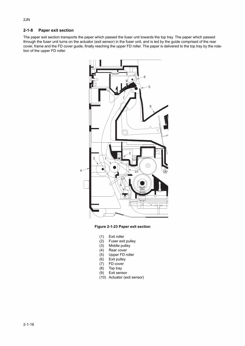
2JN
2-1-8 Paper exit sectionThe paper exit section transports the paper which passed the fuser unit towards the top tray. The paper which passed through the fuser unit turns on the actuator (exit sensor) in the fuser unit, and is led by the guide comprised of the rear cover, frame and the FD cover guide, finally reaching the upper FD roller. The paper is delivered to the top tray by the rota-tion of the upper FD roller.
Figure 2-1-23 Paper exit section
3
4 10
5
8
7
6
1
9
2
(1) Exit roller(2) Fuser exit pulley(3) Middle pulley(4) Rear cover(5) Upper FD roller(6) Exit pulley(7) FD cover(8) Top tray(9) Exit sensor(10) Actuator (exit sensor)
2-1-16
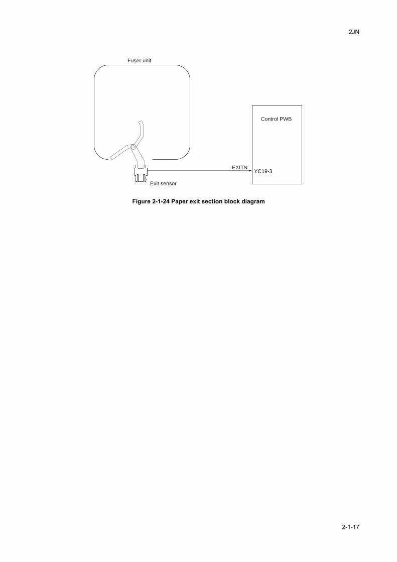
2JN
Figure 2-1-24 Paper exit section block diagram
EXITNYC19-3
Fuser unit
Exit sensor
Control PWB
2-1-17
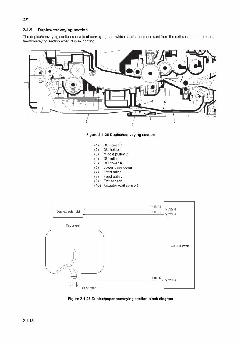
2JN
2-1-9 Duplex/conveying sectionThe duplex/conveying section consists of conveying path which sends the paper sent from the exit section to the paper feed/conveying section when duplex printing.
Figure 2-1-25 Duplex/conveying section
Figure 2-1-26 Duplex/paper conveying section block diagram
1
9
10
2
35
6
7
4
8
(1) DU cover B(2) DU holder(3) Middle pulley B(4) DU roller(5) DU cover A(6) Lower base cover(7) Feed roller(8) Feed pulley(9) Exit sensor(10) Actuator (exit sensor)
EXITN
DUDR1
DUDR2
YC19-3
YC29-1
YC29-3
Fuser unit
Exit sensor
Duplex solenoid
Control PWB
2-1-18

2JN
2-1-10 DP section
Refer to the DP’s service manual.
2-1-19

2JN
This page is intentionally left blank.
2-1-20
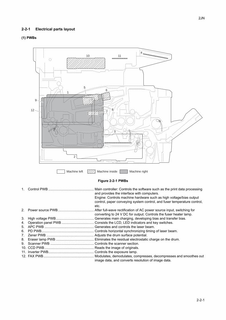
2JN
2-2 Electrical Parts Layout
2-2-1 Electrical parts layout
(1) PWBs
Figure 2-2-1 PWBs
1. Control PWB ................................................ Main controller: Controls the software such as the print data processing and provides the interface with computers.Engine: Controls machine hardware such as high voltage/bias output control, paper conveying system control, and fuser temperature control, etc.
2. Power source PWB...................................... After full-wave rectification of AC power source input, switching for converting to 24 V DC for output. Controls the fuser heater lamp.
3. High voltage PWB........................................ Generates main charging, developing bias and transfer bias.4. Operation panel PWB .................................. Consists the LCD, LED indicators and key switches.5. APC PWB .................................................... Generates and controls the laser beam.6. PD PWB....................................................... Controls horizontal synchronizing timing of laser beam.7. Zener PWB .................................................. Adjusts the drum surface potential.8. Eraser lamp PWB ........................................ Eliminates the residual electrostatic charge on the drum.9. Scanner PWB .............................................. Controls the scanner section.10. CCD PWB .................................................... Reads the image of originals.11. Inverter PWB................................................ Controls the exposure lamp.12. FAX PWB ..................................................... Modulates, demodulates, compresses, decompresses and smoothes out
image data, and converts resolution of image data.
Machine insideMachine left Machine right
1
2
4
5
78
6
9
10 11
12
3
2-2-1
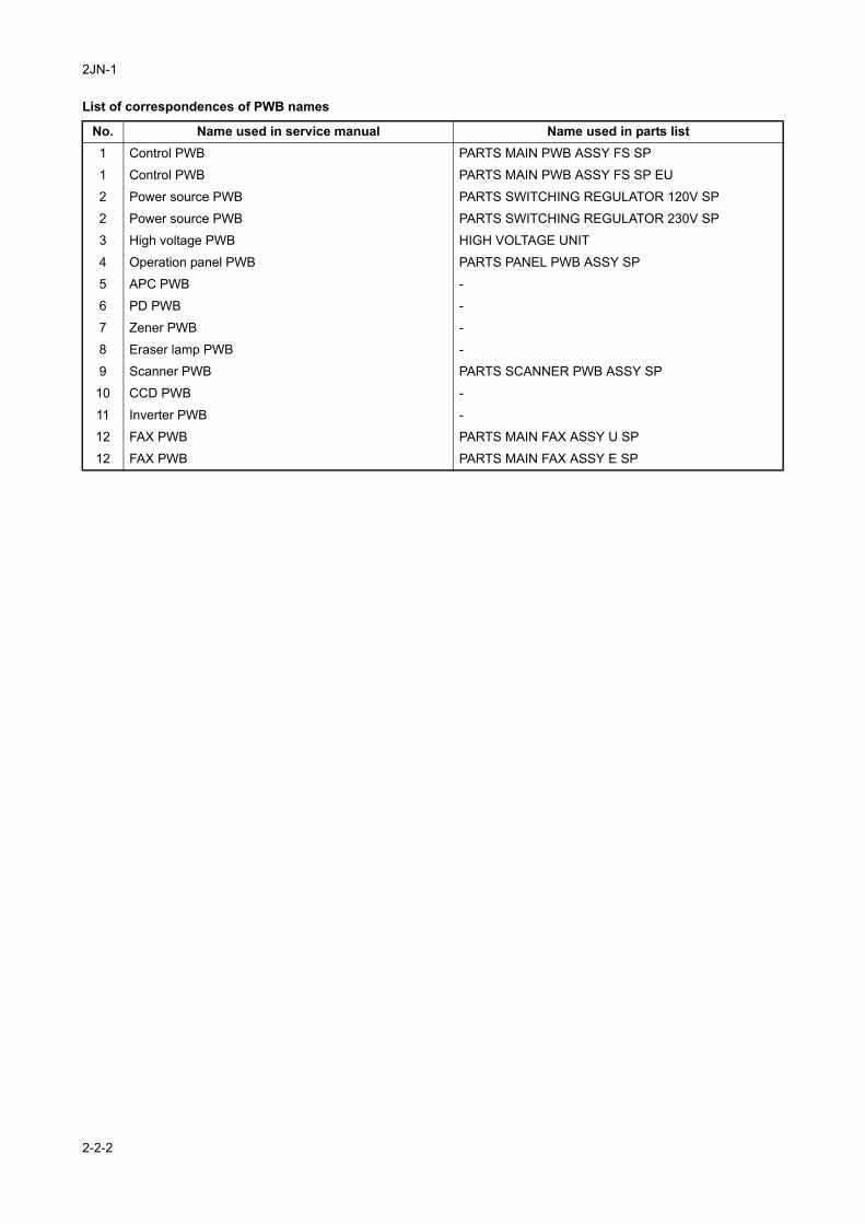
2JN-1
List of correspondences of PWB names
No. Name used in service manual Name used in parts list1 Control PWB PARTS MAIN PWB ASSY FS SP
1 Control PWB PARTS MAIN PWB ASSY FS SP EU
2 Power source PWB PARTS SWITCHING REGULATOR 120V SP
2 Power source PWB PARTS SWITCHING REGULATOR 230V SP
3 High voltage PWB HIGH VOLTAGE UNIT
4 Operation panel PWB PARTS PANEL PWB ASSY SP
5 APC PWB -
6 PD PWB -
7 Zener PWB -
8 Eraser lamp PWB -
9 Scanner PWB PARTS SCANNER PWB ASSY SP
10 CCD PWB -
11 Inverter PWB -
12 FAX PWB PARTS MAIN FAX ASSY U SP
12 FAX PWB PARTS MAIN FAX ASSY E SP
2-2-2
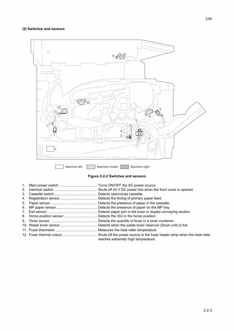
2JN
(2) Switches and sensors
Figure 2-2-2 Switches and sensors
1. Main power switch ....................................... Turns ON/OFF the AC power source.2. Interlock switch ............................................ Shuts off 24 V DC power line when the front cover is opened.3. Cassette switch............................................ Detects open/close cassette.4. Registration sensor ...................................... Detects the timing of primary paper feed.5. Paper sensor................................................ Detects the presence of paper in the cassette.6. MP paper sensor.......................................... Detects the presence of paper on the MP tray.7. Exit sensor ................................................... Detects paper jam in the fuser or duplex conveying section.8. Home position sensor .................................. Detects the ISU in the home position.9. Toner sensor ................................................ Detects the quantity of toner in a toner container.10. Waste toner sensor ...................................... Detects when the waste toner reservoir (Drum unit) is full.11. Fuser thermistor........................................... Measures the heat roller temperature.12. Fuser thermal cutout .................................... Shuts off the power source to the fuser heater lamp when the heat roller
reaches extremely high temperature.
1
2
6
8
3
4
5
7
9
12
10
11
Machine insideMachine left Machine right
2-2-3
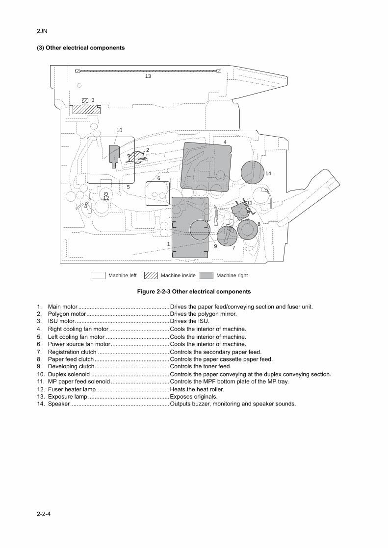
2JN
(3) Other electrical components
Figure 2-2-3 Other electrical components
1. Main motor ........................................................Drives the paper feed/conveying section and fuser unit.2. Polygon motor...................................................Drives the polygon mirror.3. ISU motor..........................................................Drives the ISU.4. Right cooling fan motor .....................................Cools the interior of machine.5. Left cooling fan motor .......................................Cools the interior of machine.6. Power source fan motor....................................Cools the interior of machine.7. Registration clutch ............................................Controls the secondary paper feed.8. Paper feed clutch ..............................................Controls the paper cassette paper feed.9. Developing clutch..............................................Controls the toner feed.10. Duplex solenoid ................................................Controls the paper conveying at the duplex conveying section.11. MP paper feed solenoid ....................................Controls the MPF bottom plate of the MP tray.12. Fuser heater lamp.............................................Heats the heat roller.13. Exposure lamp ..................................................Exposes originals.14. Speaker.............................................................Outputs buzzer, monitoring and speaker sounds.
1
2
4
3
5
6
79
12
10
13
14
8
11
Machine insideMachine left Machine right
2-2-4

2JN
(4) DP
Refer to the DP’s service manual.
2-2-5

2JN
This page is intentionally left blank.
2-2-6
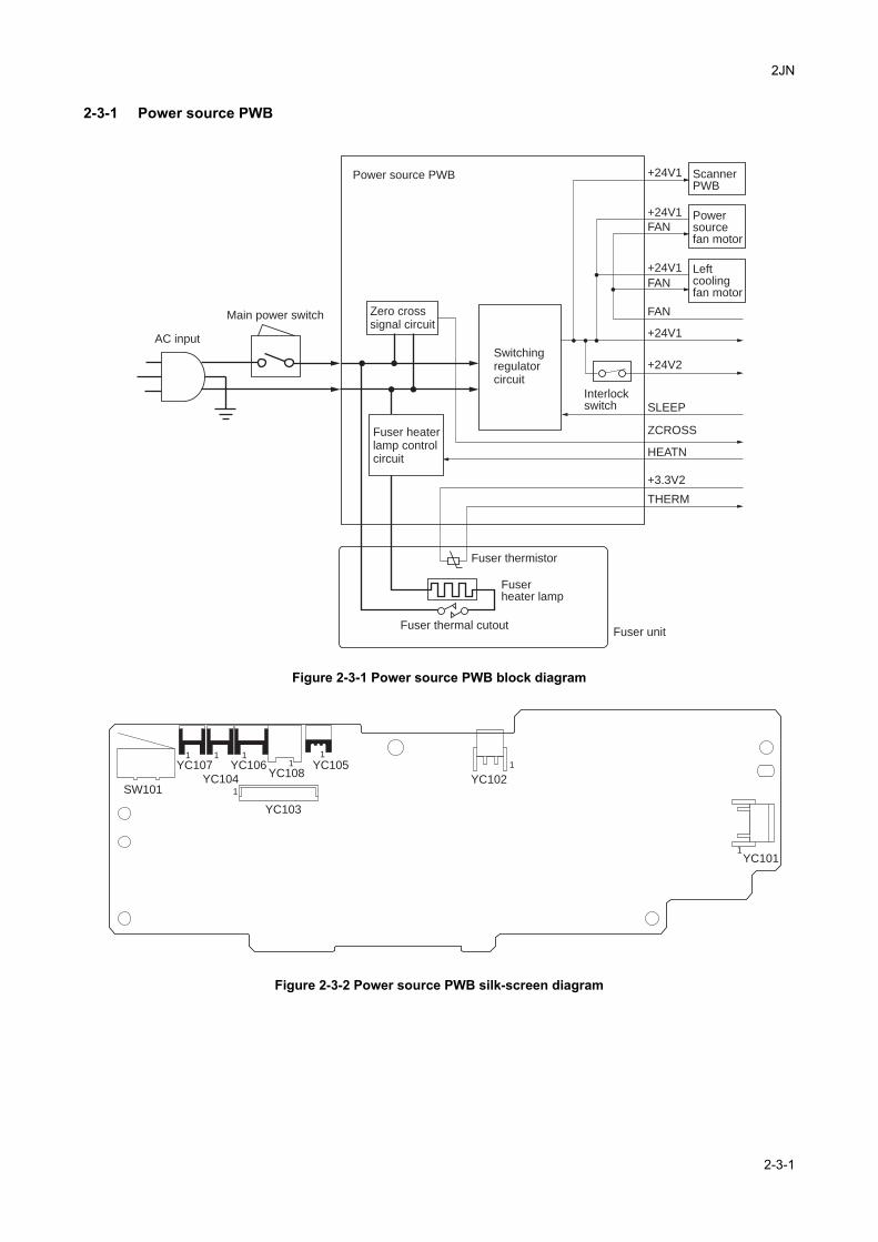
2JN
2-3 Operation of the PWBs
2-3-1 Power source PWB
Figure 2-3-1 Power source PWB block diagram
Figure 2-3-2 Power source PWB silk-screen diagram
SLEEP
+24V2
+24V1
+24V1
+24V1
+24V1
FAN
FAN
FAN
+3.3V2
ZCROSS
HEATN
THERM
Left coolingfan motor
Powersourcefan motor
ScannerPWB
Power source PWB
Fuser thermistor
Fuser thermal cutoutFuser unit
Switchingregulatorcircuit
Zero crosssignal circuit
AC input
Interlockswitch
Main power switch
Fuser heaterlamp controlcircuit
Fuserheater lamp
YC107
SW101
1 1 11
1
1
1
1
YC104
YC106YC108
YC103
YC105
YC102
YC101
2-3-1
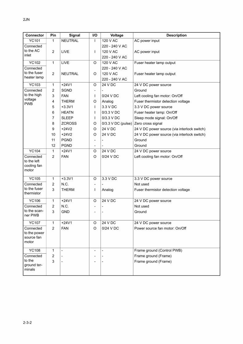
2JN
Connector Pin Signal I/O Voltage DescriptionYC101 1 NEUTRAL I 120 V AC AC power input
Connected to the AC inlet
220 - 240 V AC2 LIVE I 120 V AC AC power input
220 - 240 V ACYC102 1 LIVE O 120 V AC Fuser heater lamp output
Connected to the fuser heater lamp
220 - 240 V AC2 NEUTRAL O 120 V AC Fuser heater lamp output
220 - 240 V ACYC103 1 +24V1 O 24 V DC 24 V DC power source
Connected to the high voltage PWB
2 SGND - - Ground3 FAN I 0/24 V DC Left cooling fan motor: On/Off4 THERM O Analog Fuser thermistor detection voltage5 +3.3V1 I 3.3 V DC 3.3 V DC power source6 HEATN I 0/3.3 V DC Fuser heater lamp: On/Off7 SLEEP I 0/3.3 V DC Sleep mode signal: On/Off8 ZCROSS O 0/3.3 V DC (pulse) Zero cross signal9 +24V2 O 24 V DC 24 V DC power source (via interlock switch)10 +24V2 O 24 V DC 24 V DC power source (via interlock switch)11 PGND - - Ground12 PGND - - Ground
YC104 1 +24V1 O 24 V DC 24 V DC power sourceConnected to the left cooling fan motor
2 FAN O 0/24 V DC Left cooling fan motor: On/Off
YC105 1 +3.3V1 O 3.3 V DC 3.3 V DC power sourceConnected to the fuser thermistor
2 N.C. - - Not used3 THERM I Analog Fuser thermistor detection voltage
YC106 1 +24V1 O 24 V DC 24 V DC power sourceConnected to the scan-ner PWB
2 N.C. - - Not used3 GND - - Ground
YC107 1 +24V1 O 24 V DC 24 V DC power sourceConnected to the power source fan motor
2 FAN O 0/24 V DC Power source fan motor: On/Off
YC108 1 - - - Frame ground (Control PWB)Connected to the ground ter-minals
2 - - - Frame ground (Frame)3 - - - Frame ground (Frame)
2-3-2
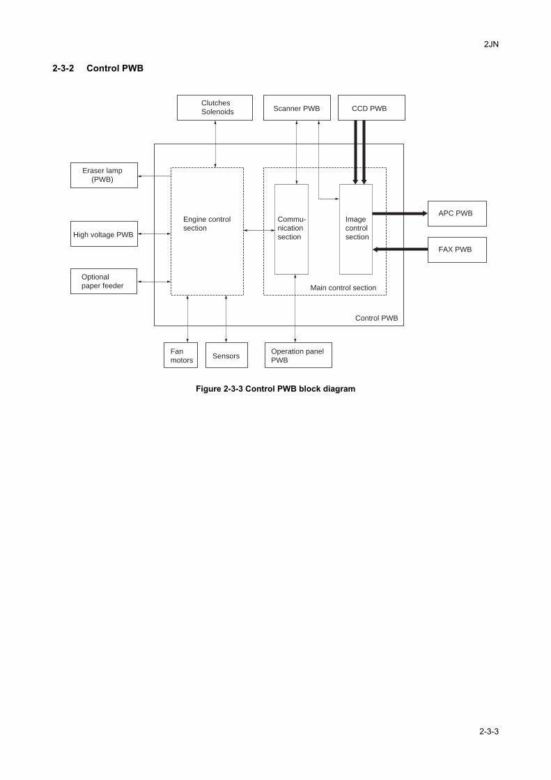
2JN
2-3-2 Control PWB
Figure 2-3-3 Control PWB block diagram
Clutches
Solenoids Scanner PWB CCD PWB
APC PWB
FAX PWB
Operation panel
PWBSensors
Fan
motors
Optional
paper feeder
Engine control
section
Main control section
Commu-
nication
section
Image
control
section
Control PWB
High voltage PWB
Eraser lamp
(PWB)
2-3-3
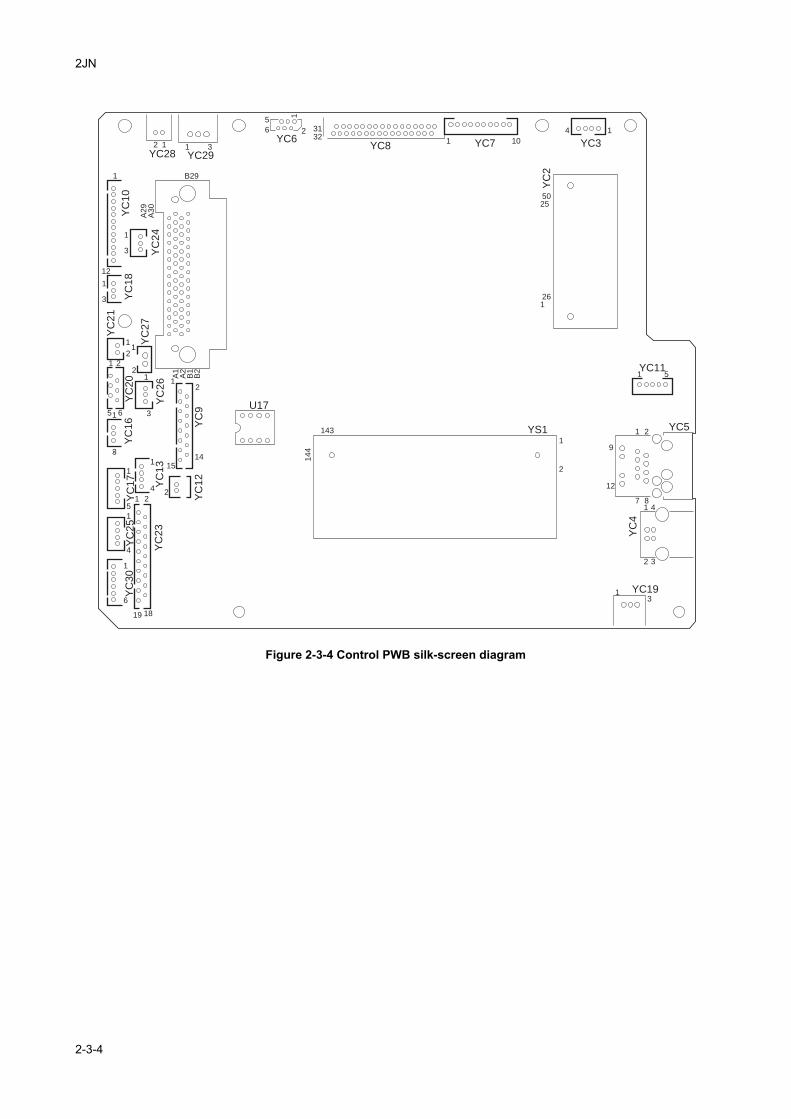
2JN
Figure 2-3-4 Control PWB silk-screen diagram
2 1 1YC29YC28
3
5
6
YC6YC8
2 3132
1 10
4 1
YC7 YC3
YC
2
5025
261
1
YC11
YC5
1
1
91
2
YS1143
U17
144
12
2
7
YC
4
841
32
1 YC193
5
19
YC
30
YC
23
YC
25
YC
17
YC
13
YC
16
YC
20
YC
27
A1
A2
B1
B2
YC
21
YC
18
YC
24
YC
10
A29
B29
A30
YC
26
YC
9Y
C12
6
1
1
11
12
1
1
1
1
3
1
1
3
12
1
2
2
5 6
1
3
3
2
24
1415
4
51 2
18
2-3-4
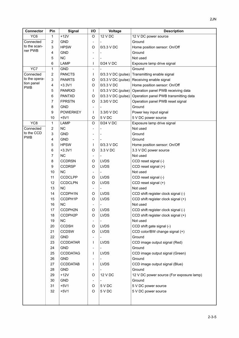
2JN
Connector Pin Signal I/O Voltage DescriptionYC6 1 +12V O 12 V DC 12 V DC power source
Connected to the scan-ner PWB
2 GND - - Ground3 HPSW O 0/3.3 V DC Home position sensor: On/Off4 GND - - Ground5 NC - - Not used6 LAMP I 0/24 V DC Exposure lamp drive signal
YC7 1 GND - - GroundConnected to the opera-tion panel PWB
2 PANCTS I 0/3.3 V DC (pulse) Transmitting enable signal3 PANRTS O 0/3.3 V DC (pulse) Receiving enable signal4 +3.3V1 O 0/3.3 V DC Home position sensor: On/Off5 PANRXD I 0/3.3 V DC (pulse) Operation panel PWB receiving data6 PANTXD O 0/3.3 V DC (pulse) Operation panel PWB transmitting data7 FPRSTN O 3.3/0 V DC Operation panel PWB reset signal8 GND - - Ground9 POWERKEY I 3.3/0 V DC Power key input signal10 +5V1 O 5 V DC 5 V DC power source
YC8 1 LAMP O 0/24 V DC Exposure lamp drive signalConnected to the CCD PWB
2 NC - - Not used3 GND - - Ground4 GND - - Ground5 HPSW I 0/3.3 V DC Home position sensor: On/Off6 +3.3V1 O 3.3 V DC 3.3 V DC power source7 NC - - Not used8 CCDRSN O LVDS CCD reset signal (-)9 CCDRSP O LVDS CCD reset signal (+)10 NC - - Not used11 CCDCLPP O LVDS CCD reset signal (-)12 CCDCLPN O LVDS CCD reset signal (+)13 NC - - Not used14 CCDPH1N O LVDS CCD shift register clock signal (-)15 CCDPH1P O LVDS CCD shift register clock signal (+)16 NC - - Not used17 CCDPH2N O LVDS CCD shift register clock signal (-)18 CCDPH2P O LVDS CCD shift register clock signal (+)19 NC - - Not used20 CCDSH O LVDS CCD shift gate signal (-)21 CCDSW O LVDS CCD color/BW change signal (+)22 GND - - Ground23 CCDDATAR I LVDS CCD image output signal (Red)24 GND - - Ground25 CCDDATAG I LVDS CCD image output signal (Green)26 GND - - Ground27 CCDDATAB I LVDS CCD image output signal (Blue)28 GND - - Ground29 +12V O 12 V DC 12 V DC power source (For exposure lamp)30 GND - - Ground31 +5V1 O 5 V DC 5 V DC power source32 +5V1 O 5 V DC 5 V DC power source
2-3-5
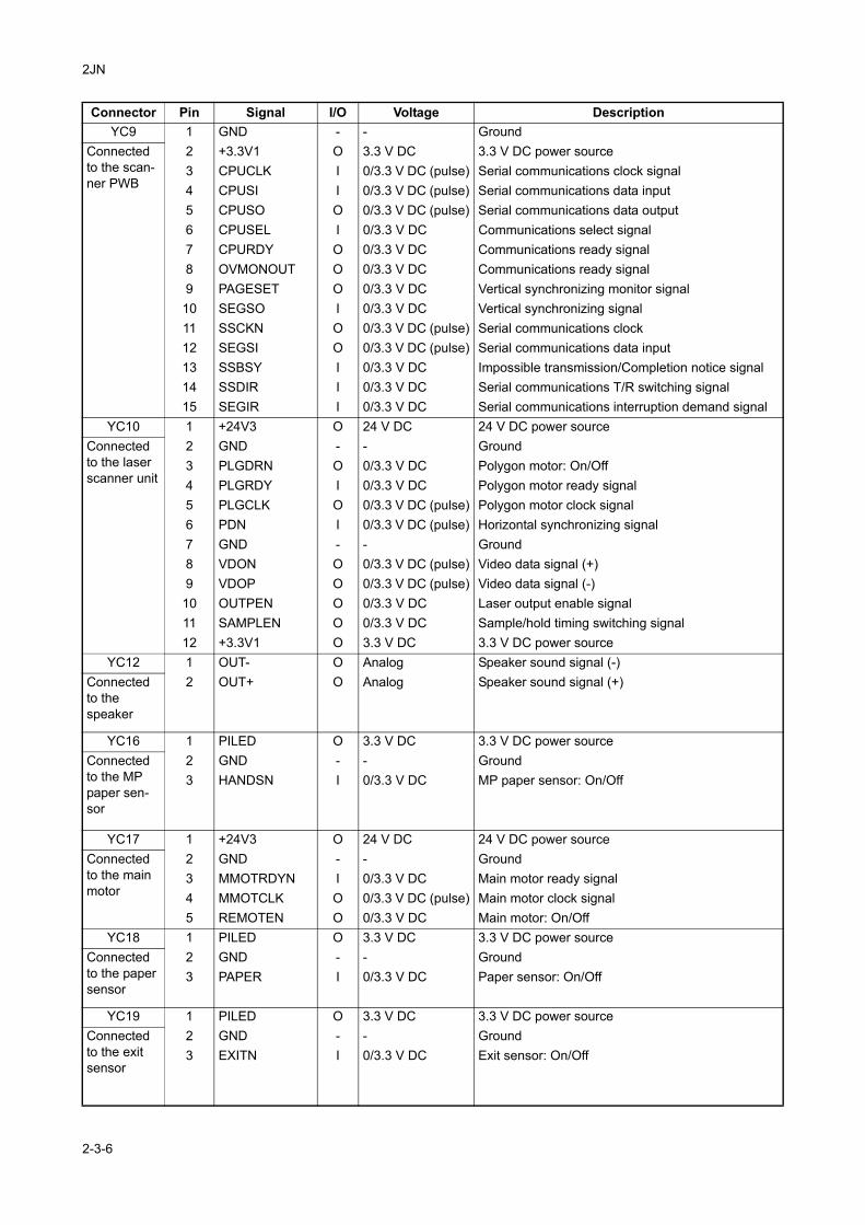
2JN
YC9 1 GND - - GroundConnected to the scan-ner PWB
2 +3.3V1 O 3.3 V DC 3.3 V DC power source3 CPUCLK I 0/3.3 V DC (pulse) Serial communications clock signal4 CPUSI I 0/3.3 V DC (pulse) Serial communications data input5 CPUSO O 0/3.3 V DC (pulse) Serial communications data output6 CPUSEL I 0/3.3 V DC Communications select signal7 CPURDY O 0/3.3 V DC Communications ready signal8 OVMONOUT O 0/3.3 V DC Communications ready signal9 PAGESET O 0/3.3 V DC Vertical synchronizing monitor signal10 SEGSO I 0/3.3 V DC Vertical synchronizing signal11 SSCKN O 0/3.3 V DC (pulse) Serial communications clock12 SEGSI O 0/3.3 V DC (pulse) Serial communications data input13 SSBSY I 0/3.3 V DC Impossible transmission/Completion notice signal14 SSDIR I 0/3.3 V DC Serial communications T/R switching signal15 SEGIR I 0/3.3 V DC Serial communications interruption demand signal
YC10 1 +24V3 O 24 V DC 24 V DC power sourceConnected to the laser scanner unit
2 GND - - Ground3 PLGDRN O 0/3.3 V DC Polygon motor: On/Off4 PLGRDY I 0/3.3 V DC Polygon motor ready signal5 PLGCLK O 0/3.3 V DC (pulse) Polygon motor clock signal6 PDN I 0/3.3 V DC (pulse) Horizontal synchronizing signal7 GND - - Ground8 VDON O 0/3.3 V DC (pulse) Video data signal (+)9 VDOP O 0/3.3 V DC (pulse) Video data signal (-)10 OUTPEN O 0/3.3 V DC Laser output enable signal11 SAMPLEN O 0/3.3 V DC Sample/hold timing switching signal12 +3.3V1 O 3.3 V DC 3.3 V DC power source
YC12 1 OUT- O Analog Speaker sound signal (-)Connected to the speaker
2 OUT+ O Analog Speaker sound signal (+)
YC16 1 PILED O 3.3 V DC 3.3 V DC power sourceConnected to the MP paper sen-sor
2 GND - - Ground3 HANDSN I 0/3.3 V DC MP paper sensor: On/Off
YC17 1 +24V3 O 24 V DC 24 V DC power sourceConnected to the main motor
2 GND - - Ground3 MMOTRDYN I 0/3.3 V DC Main motor ready signal4 MMOTCLK O 0/3.3 V DC (pulse) Main motor clock signal5 REMOTEN O 0/3.3 V DC Main motor: On/Off
YC18 1 PILED O 3.3 V DC 3.3 V DC power sourceConnected to the paper sensor
2 GND - - Ground3 PAPER I 0/3.3 V DC Paper sensor: On/Off
YC19 1 PILED O 3.3 V DC 3.3 V DC power sourceConnected to the exit sensor
2 GND - - Ground3 EXITN I 0/3.3 V DC Exit sensor: On/Off
Connector Pin Signal I/O Voltage Description
2-3-6
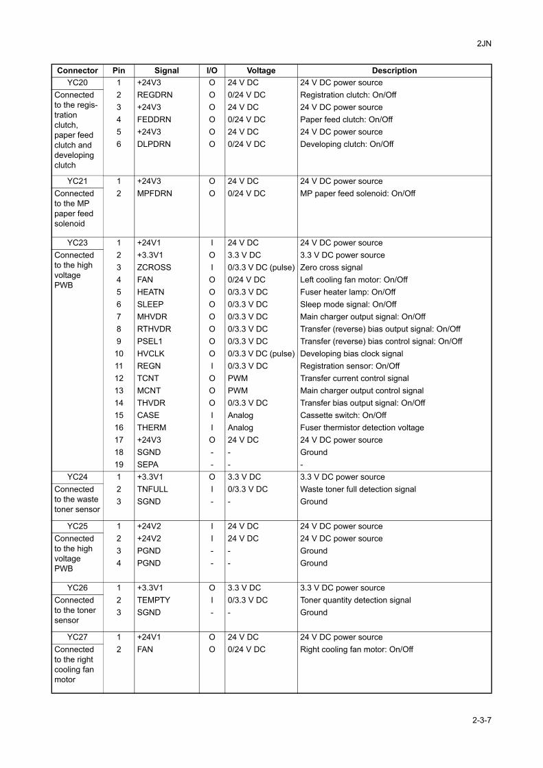
2JN
YC20 1 +24V3 O 24 V DC 24 V DC power sourceConnected to the regis-tration clutch, paper feed clutch and developing clutch
2 REGDRN O 0/24 V DC Registration clutch: On/Off3 +24V3 O 24 V DC 24 V DC power source4 FEDDRN O 0/24 V DC Paper feed clutch: On/Off5 +24V3 O 24 V DC 24 V DC power source6 DLPDRN O 0/24 V DC Developing clutch: On/Off
YC21 1 +24V3 O 24 V DC 24 V DC power sourceConnected to the MP paper feed solenoid
2 MPFDRN O 0/24 V DC MP paper feed solenoid: On/Off
YC23 1 +24V1 I 24 V DC 24 V DC power sourceConnected to the high voltage PWB
2 +3.3V1 O 3.3 V DC 3.3 V DC power source3 ZCROSS I 0/3.3 V DC (pulse) Zero cross signal4 FAN O 0/24 V DC Left cooling fan motor: On/Off5 HEATN O 0/3.3 V DC Fuser heater lamp: On/Off6 SLEEP O 0/3.3 V DC Sleep mode signal: On/Off7 MHVDR O 0/3.3 V DC Main charger output signal: On/Off8 RTHVDR O 0/3.3 V DC Transfer (reverse) bias output signal: On/Off9 PSEL1 O 0/3.3 V DC Transfer (reverse) bias control signal: On/Off10 HVCLK O 0/3.3 V DC (pulse) Developing bias clock signal11 REGN I 0/3.3 V DC Registration sensor: On/Off12 TCNT O PWM Transfer current control signal13 MCNT O PWM Main charger output control signal14 THVDR O 0/3.3 V DC Transfer bias output signal: On/Off15 CASE I Analog Cassette switch: On/Off16 THERM I Analog Fuser thermistor detection voltage17 +24V3 O 24 V DC 24 V DC power source18 SGND - - Ground19 SEPA - - -
YC24 1 +3.3V1 O 3.3 V DC 3.3 V DC power sourceConnected to the waste toner sensor
2 TNFULL I 0/3.3 V DC Waste toner full detection signal3 SGND - - Ground
YC25 1 +24V2 I 24 V DC 24 V DC power sourceConnected to the high voltage PWB
2 +24V2 I 24 V DC 24 V DC power source3 PGND - - Ground4 PGND - - Ground
YC26 1 +3.3V1 O 3.3 V DC 3.3 V DC power sourceConnected to the toner sensor
2 TEMPTY I 0/3.3 V DC Toner quantity detection signal3 SGND - - Ground
YC27 1 +24V1 O 24 V DC 24 V DC power sourceConnected to the right cooling fan motor
2 FAN O 0/24 V DC Right cooling fan motor: On/Off
Connector Pin Signal I/O Voltage Description
2-3-7
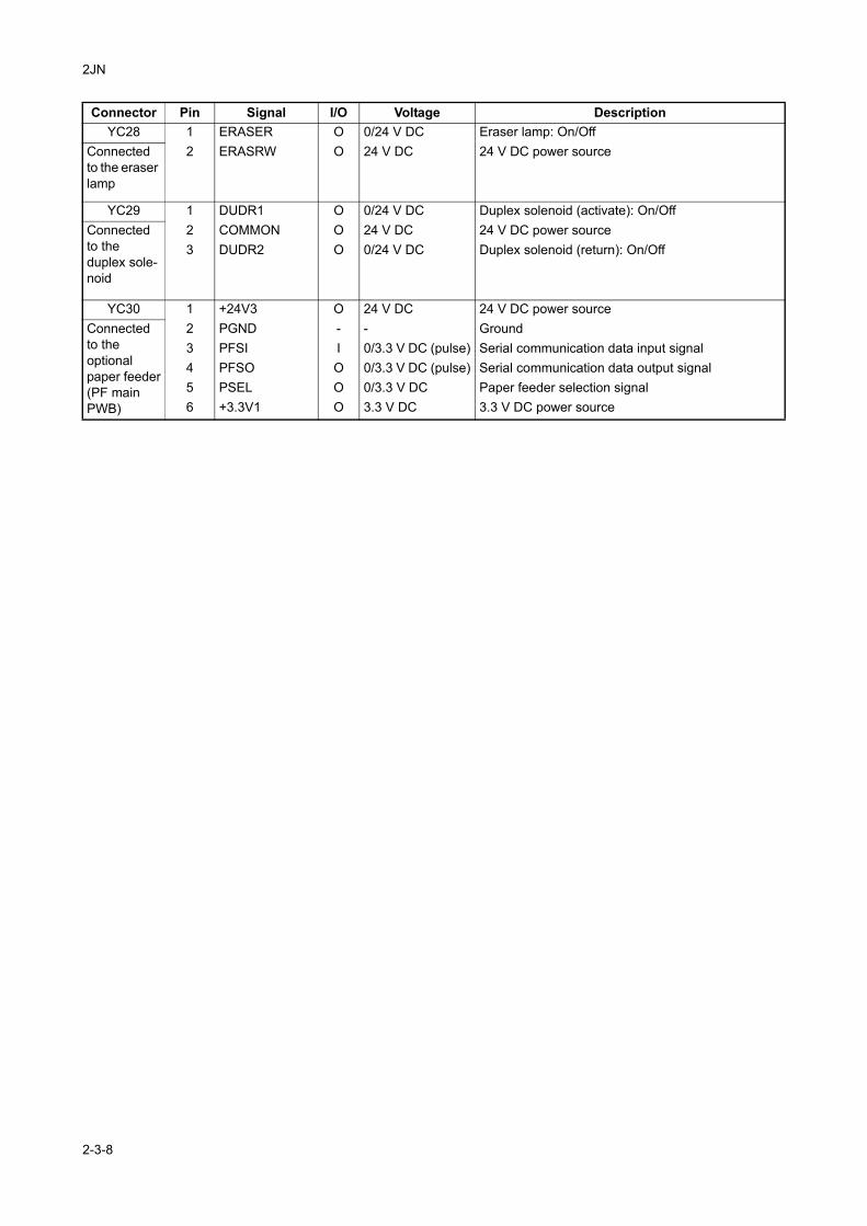
2JN
YC28 1 ERASER O 0/24 V DC Eraser lamp: On/OffConnected to the eraser lamp
2 ERASRW O 24 V DC 24 V DC power source
YC29 1 DUDR1 O 0/24 V DC Duplex solenoid (activate): On/OffConnected to the duplex sole-noid
2 COMMON O 24 V DC 24 V DC power source3 DUDR2 O 0/24 V DC Duplex solenoid (return): On/Off
YC30 1 +24V3 O 24 V DC 24 V DC power sourceConnected to the optional paper feeder(PF main PWB)
2 PGND - - Ground3 PFSI I 0/3.3 V DC (pulse) Serial communication data input signal4 PFSO O 0/3.3 V DC (pulse) Serial communication data output signal5 PSEL O 0/3.3 V DC Paper feeder selection signal6 +3.3V1 O 3.3 V DC 3.3 V DC power source
Connector Pin Signal I/O Voltage Description
2-3-8
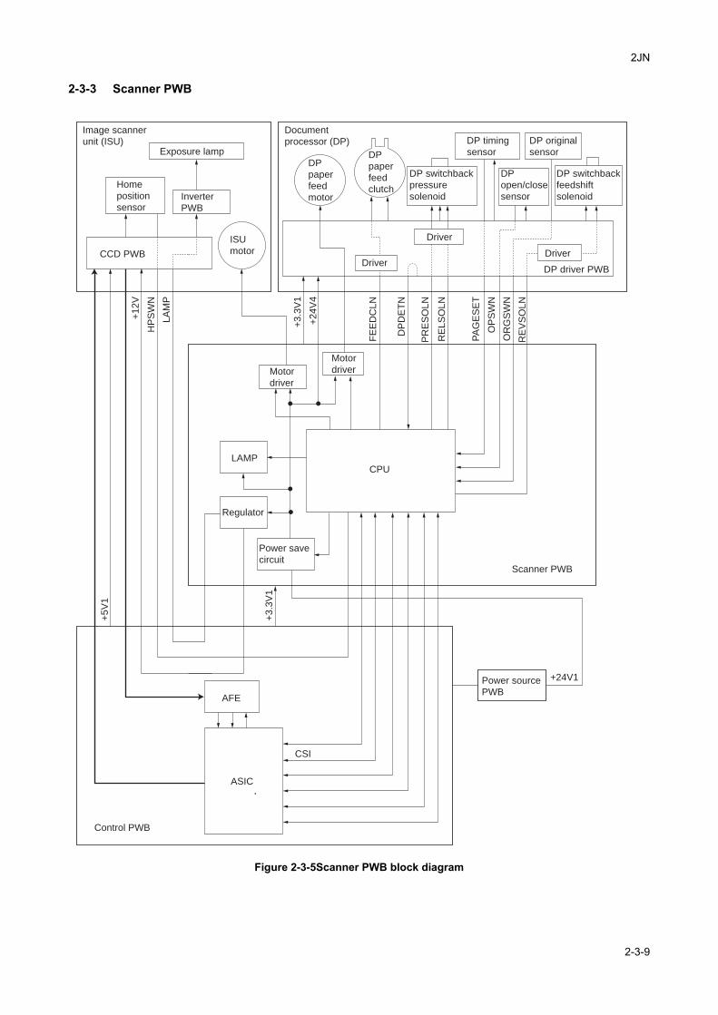
2JN
2-3-3 Scanner PWB
Figure 2-3-5Scanner PWB block diagram
Image scanner
unit (ISU)
Scanner PWB
Regulator
LAMPCPU
Control PWB
ASIC
AFE
Power save
circuit
Power source
PWB
Document
processor (DP)Exposure lamp
ISU
motorCCD PWB
Home
position
sensorInverter
PWB
Driver
Driver
Driver
Motor
driverMotor
driverF
EE
DC
LN
DP
DE
TN
PR
ES
OL
N
RE
LS
OL
N
PA
GE
SE
T
OP
SW
N
OR
GS
WN
RE
VS
OL
N
+3
.3V
1
+2
4V
4
LA
MP
HP
SW
N
+1
2V
CSI
+5
V1
+3
.3V
1
+24V1
DP driver PWB
DP timing
sensor
DP original
sensor
DP
open/close
sensor
DP
paper
feed
motor
DP
paper
feed
clutch
DP switchback
feedshift
solenoid
DP switchback
pressure
solenoid
2-3-9
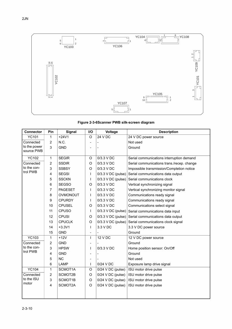
2JN
Figure 2-3-6Scanner PWB silk-screen diagram
Connector Pin Signal I/O Voltage DescriptionYC101 1 +24V1 O 24 V DC 24 V DC power source
Connected to the power source PWB
2 N.C. - - Not used3 GND - - Ground
YC102 1 SEGIR O 0/3.3 V DC Serial communications interruption demandConnected to the con-trol PWB
2 SSDIR O 0/3.3 V DC Serial communications trans./recep. change3 SSBSY O 0/3.3 V DC Impossible transmission/Completion notice4 SEGSI I 0/3.3 V DC (pulse) Serial communications data output5 SSCKN I 0/3.3 V DC (pulse) Serial communications clock6 SEGSO O 0/3.3 V DC Vertical synchronizing signal7 PAGESET I 0/3.3 V DC Vertical synchronizing monitor signal8 OVMONOUT I 0/3.3 V DC Communications ready signal9 CPURDY I 0/3.3 V DC Communications ready signal10 CPUSEL O 0/3.3 V DC Communications select signal11 CPUSO I 0/3.3 V DC (pulse) Serial communications data input12 CPUSI O 0/3.3 V DC (pulse) Serial communications data output13 CPUCLK O 0/3.3 V DC (pulse) Serial communications clock signal14 +3.3V1 I 3.3 V DC 3.3 V DC power source15 GND - - Ground
YC103 1 +12V I 12 V DC 12 V DC power sourceConnected to the con-trol PWB
2 GND - - Ground3 HPSW I 0/3.3 V DC Home position sensor: On/Off4 GND - - Ground5 NC - - Not used6 LAMP I 0/24 V DC Exposure lamp drive signal
YC104 1 SCMOT1A O 0/24 V DC (pulse) ISU motor drive pulseConnected to the ISU motor
2 SCMOT2B O 0/24 V DC (pulse) ISU motor drive pulse3 SCMOT1B O 0/24 V DC (pulse) ISU motor drive pulse4 SCMOT2A O 0/24 V DC (pulse) ISU motor drive pulse
YC
10
1Y
C1
09
YC108YC104
YC106
YC107
YC105
YC103
YC
10
2
11
1
11
15
9
10
1
2
71
5
6
14
15
2 1
2
4
6
23
2-3-10
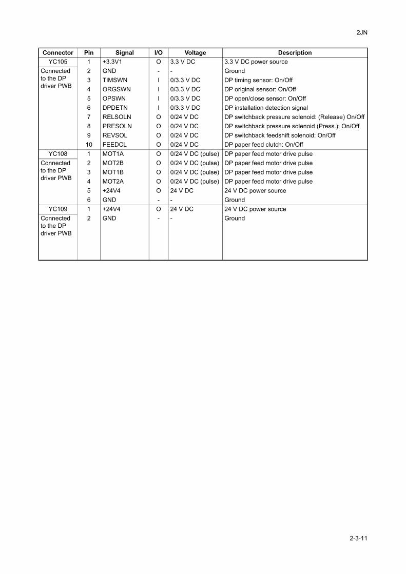
2JN
YC105 1 +3.3V1 O 3.3 V DC 3.3 V DC power sourceConnected to the DP driver PWB
2 GND - - Ground3 TIMSWN I 0/3.3 V DC DP timing sensor: On/Off4 ORGSWN I 0/3.3 V DC DP original sensor: On/Off5 OPSWN I 0/3.3 V DC DP open/close sensor: On/Off6 DPDETN I 0/3.3 V DC DP installation detection signal7 RELSOLN O 0/24 V DC DP switchback pressure solenoid: (Release) On/Off8 PRESOLN O 0/24 V DC DP switchback pressure solenoid (Press.): On/Off9 REVSOL O 0/24 V DC DP switchback feedshift solenoid: On/Off10 FEEDCL O 0/24 V DC DP paper feed clutch: On/Off
YC108 1 MOT1A O 0/24 V DC (pulse) DP paper feed motor drive pulseConnected to the DP driver PWB
2 MOT2B O 0/24 V DC (pulse) DP paper feed motor drive pulse3 MOT1B O 0/24 V DC (pulse) DP paper feed motor drive pulse4 MOT2A O 0/24 V DC (pulse) DP paper feed motor drive pulse5 +24V4 O 24 V DC 24 V DC power source6 GND - - Ground
YC109 1 +24V4 O 24 V DC 24 V DC power sourceConnected to the DP driver PWB
2 GND - - Ground
Connector Pin Signal I/O Voltage Description
2-3-11

2JN
2-3-4 DP driver PWBRefer to the DP’s service manual.
2-3-12
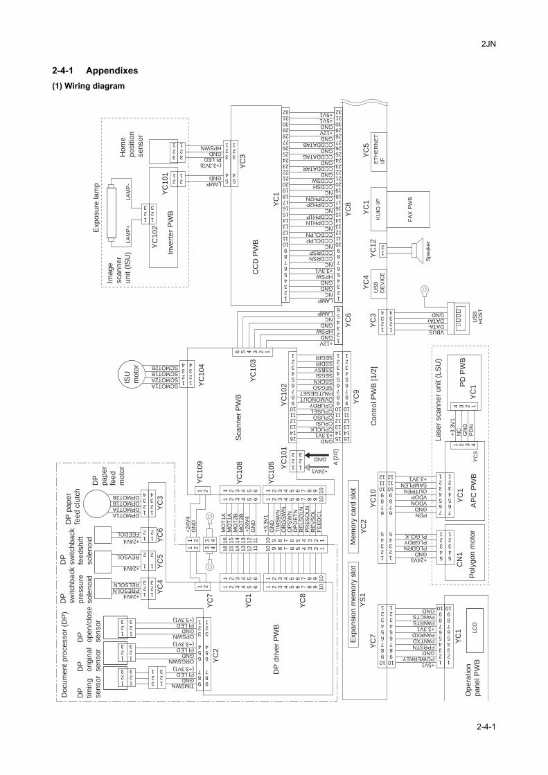
2JN
2-4 Appendixes
2-4-1 Appendixes(1) Wiring diagram
KU
IO I
/F
FA
X P
WB
+24V3 GND PLGDRNPLGRDYPLGCLK
PDN GND VDONVDOPOUTPENSAMPLEN+3.3V1
US
BD
EV
ICE
ET
HE
RN
ET
I/F
+5V1POWERKEYGND FPRSTNPANTXDPANRXD+3.3V1PANRTSPANCTSGND
YC
7
YC
1Y
C1
YC
1Y
C3
YC
10
12345678910
12345678910
CN
1
+3.3V1CPUCLKCPUSICPUSOCPUSELCPURDYOVMONOUTPAUTGESETSEGSOSSCKNSEGSISSBSYSSDIRSEGIR
LAMPGND
PI LEDGNDHPSWN
54
321
YC
6Y
C9
YC
3Y
C4
YC
12
YC
1Y
C5
YC
2Y
S1
YC
8
123
123
LAMPNC
GNDGND
HPSW+3.3V1
+24V1
GND
GND
GND
GND
123
123
YC
1
YC
3
YC
10
1
YC
10
2
10987654321
10987654321
7654321
7654321
54321
54321
12345
6789101112
12345
6789101112
VBUSDATA-DATA+GND
1234
1234
1 2 3 4
+3
.3V
1N
C
GN
D
PD
N
4 3 2 1
12
54
321
DPMOT1ADPMOT2ADPMOT1BDPMOT2B
OPSWNGND
GND
PI LED
PI LED
TIMSWNGNDPI LED
987
654
321
987
654
321
ORGSWN
1234
MO
T1
AM
OT
1A
MO
T2
BM
OT
2B
+24V
4G
ND
+3
.3V
1G
ND
TIM
SW
NO
RG
SW
NO
PS
WN
DP
DE
TN
RE
LS
OLN
PR
ES
OL
NR
EV
SO
LF
EE
DC
L
YC
2
YC
4Y
C5
YC
6Y
C3
YC
7
YC
1
YC
8+24V4PRESOLNRELSOLN
+24V4
REVSOL
+24V4
FEEDCL
123
123
123
151413121110987654321
151413121110987654321
151413121110987654321
21
21
321
321
123
123
123
US
B
HO
ST
SpeakerLA
MP
+LA
MP
-
1 21 2
3 43 4
321
123
(+3.3V3)
(+3.3V1)
(+3.3V1)
(+3.3V1)
1234567891011121314151617181920212223242526272829303132
1234567891011121314151617181920212223242526272829303132
NCCCDRSNCCDRSPNCCCDCLPPCCDCLPNNCCCDPH1NCCDPH1PNCCCDPH2PCCDPH2NNCCCDSHCCDSWGND
GND
GND
GND
GND
CCDDATAR
CCDDATAG
CCDDATAB
+12V
+5V1+5V1
123456
+12V
HPSW
NCLAMP
16
15
14
13
12
11
10 9 8 7 6 5 4 3 2 1
16
15
14
13
12
11
10 9 8 7 6 5 4 3 2 1
6 5 4 3 2 1
1 2 3 4 5 6 1 2 3 4 5 6 7 8 9 10
1 2 3 4 5 6
1 2 3 4 5 6
1 2 3 4 5 6
1 2 3 4 5 6 7 8 9 10
1 2 3 4 5 6 7 8 9 10
1 2 3 4 5 6 7 8 9 10
1 21 2
123
1
2
12
1234
SCMOT1ASCMOT2ASCMOT1BSCMOT2B
1234
1234
123
1
2
12
YC
10
5
YC
10
8
YC
10
9Y
C1
04
YC
10
3
YC
10
2Y
C1
01
+24V
4
GN
D
A [2/2
]
LC
D
Me
mo
ry c
ard
slo
tE
xp
an
sio
n m
em
ory
slo
t
Co
ntr
ol P
WB
[1
/2]
Sca
nn
er
PW
B
ISU
mo
tor
CC
D P
WB
Inve
rte
r P
WB
Exp
osu
re la
mp
Ho
me
po
sitio
n
se
nso
r
Ima
ge
sca
nn
er
un
it (
ISU
)
Po
lyg
on
mo
tor
Op
era
tio
n
pa
ne
l P
WB
DP
dri
ve
r P
WB
DP
tim
ing
se
nso
r
DP
ori
gin
al
se
nso
r
DP
op
en
/clo
se
se
nso
rD
P
pa
pe
r
fee
d
mo
tor
DP
pa
pe
r
fee
d c
lutc
h
DP
sw
itch
ba
ck
fee
dsh
ift
so
len
oid
DP
sw
itch
ba
ck
pre
ssu
re
so
len
oid
Do
cu
me
nt
pro
ce
sso
r (D
P)
AP
C P
WB
PD
PW
B
La
se
r sca
nn
er
un
it (
LS
U)
2-4-1
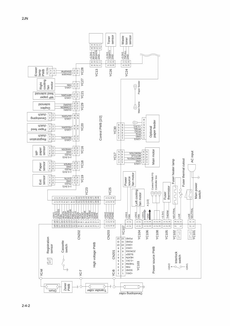
2JN
YC
102
YC
105
YC
108
YC
106
YC
104
YC
107
YC
103
YC
101
1
2
3
4
5
6
7
8
9
10
11
12
1
2
3
4
5
6
7
8
9
10
11
12
+24V1
SGND
FAN
THERM
+3.3V1
HEATN
SLEEP
ZCROSS
+24V2
+24V2
PGND
PGND
+24V
2
+24V
1
+24V3GNDMMOTRDYNMOTCLKREMOTEN
A [1/2
]
12345
12345
12345
12345
YC
20
YC
27
YC
18
YC
21
YC
29
YC
16
YC
19
YC
17
YC
30
YC
28
YC
25
YC
23
CN
202
CN
203
CN
201
PILED GND PAPER
+24V3REGDRN
+24V3FEDDRN
DUDR1COMMONDUDR2
+24V3DLPDRN
+24V3MPFDRN
PILED GNDHANDSN
12
34
56
12
34
56
+24V1FAN
+24V3 GND PFSIPFSOPFSEL+3.3V1
+24V
1+
3.3
V1
ZC
RO
SS
FA
NH
EA
TN
SL
EE
PM
HV
DR
RT
HV
DR
PS
EL1
HV
CLK
RE
GN
TC
NT
MC
NT
TH
VD
RC
AS
ET
HE
RM
+24V
3S
GN
DS
EP
A
ERASERERASPW
12
12
21
21
12
12
12
12
123
123
123
123
123
123
123
123
321
321
321
321
321
321
21
21
21
21
21
21
+24V
2+
24V
2P
GN
DP
GN
D
1 2 3 4
1 2 3 4
1 2 3 4
1 2 3 419
18
17
16
15
14
13
12
11
YC
-M
YC
-T
YC
-B
10 9 8 7 6 5 4 3 2 1
19
18
17
16
15
14
13
12
11
10 9 8 7 6 5 4 3 2 1
1 2 3 4 5 6 7 8 9 10
11
12
13
14
15
16
17
18
19
1 2 3 4 5 6 7 8 9 10
11
12
13
14
15
16
17
18
19
PILED GND EXITN
123456
123456
1 2 3
1 2 3
1 2 3
1 2 3
1 2 3
1 2 3
2 1
3 2 1L
IVE
+3
.3V
1
TH
ER
M
+24V
1
FA
N
+24V
1
FA
N
1 21 2
1 21 2
2 1
2 1
LIV
E
NE
UT
RA
L
NE
UT
RA
L
+3
.3V
1T
EM
PT
YG
ND
4 3 2 1
4 3 2 1
4 3 2 1
4 3 2 1
+3
.3V
1T
NF
ULL
GN
D
1 2 3
1 2 3
1 2 3
1 2 3
YC
24
YC
13
YC
26
+3
.3V
1R
FC
LK
RF
DA
TA
GN
D
YC
701
12345678
(+3.3V2)
(+3.3V2)
(+3.3V2)
+24V
1
GN
D
AC
in
pu
t
Drum Transfer rollerDeveloping roller
Le
ft c
oo
ling
fan
mo
tor
Po
we
r
so
urc
e
fan
mo
tor
Ma
in p
ow
er
sw
itch
Inte
rlo
ck
sw
itch
MP
pa
pe
r
se
nso
r
Pa
pe
r
se
nso
r
Registration
clutch
Paper feed
clutch
Developing
clutch
Duplex
solenoid
MP paper
feed solenoid
Hig
h v
olta
ge
PW
B
Ca
sse
tte
sw
itch
Re
gis
tra
tio
n
se
nso
r
Po
we
r so
urc
e P
WB
Ma
in m
oto
rO
ptio
na
l
pa
pe
r fe
ed
er
Co
ntr
ol P
WB
[2
/2]
Rig
ht
co
olin
g
fan
mo
tor
Fu
se
r
the
rmis
tor F
use
r th
erm
al cu
tou
t
Fu
se
r h
ea
ter
lam
p
Contr
ol P
WB
FG
Main
fra
me
Paper
feeder
Contr
olle
r box
To
ne
r
se
nso
r
Wa
ste
ton
er
se
nso
r
Era
se
r
lam
p
PW
BE
xit
se
nso
r
Ze
ne
r
PW
B
2-4-2
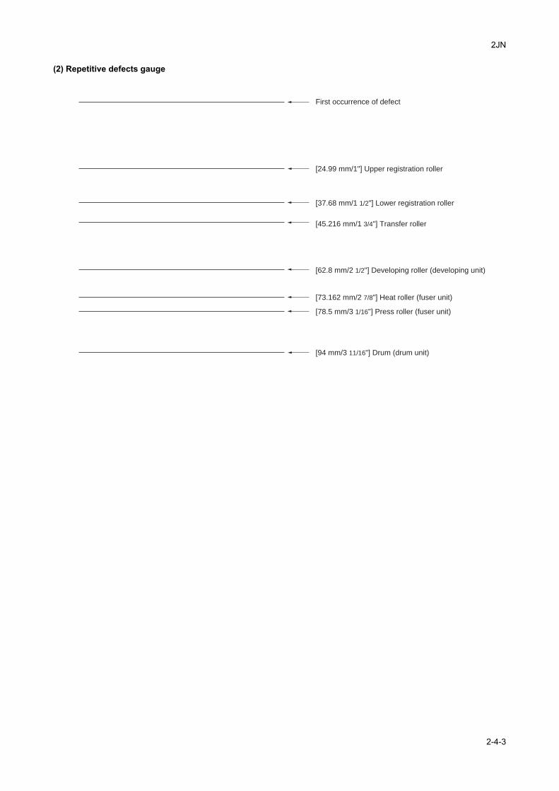
2JN
(2) Repetitive defects gauge
First occurrence of defect
[24.99 mm/1"] Upper registration roller
[37.68 mm/1 1/2"] Lower registration roller
[62.8 mm/2 1/2"] Developing roller (developing unit)
[45.216 mm/1 3/4"] Transfer roller
[73.162 mm/2 7/8"] Heat roller (fuser unit)
[78.5 mm/3 1/16"] Press roller (fuser unit)
[94 mm/3 11/16"] Drum (drum unit)
2-4-3
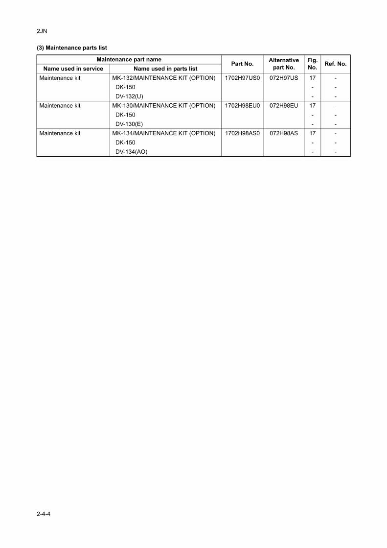
2JN
(3) Maintenance parts list
Maintenance part namePart No. Alternative
part No.Fig. No. Ref. No.
Name used in service Name used in parts listMaintenance kit MK-132/MAINTENANCE KIT (OPTION) 1702H97US0 072H97US 17 -
DK-150 - - DV-132(U) - -
Maintenance kit MK-130/MAINTENANCE KIT (OPTION) 1702H98EU0 072H98EU 17 - DK-150 - - DV-130(E) - -
Maintenance kit MK-134/MAINTENANCE KIT (OPTION) 1702H98AS0 072H98AS 17 - DK-150 - - DV-134(AO) - -
2-4-4


![Olevia 232-s12 Sm Rev1 [ET]](https://img.dokumen.tips/doc/110x75/545075d0b1af9f0d098b4be2/olevia-232-s12-sm-rev1-et.jpg)