Embed Size (px)
Citation preview

SERVICEMANUAL
Published in June 2006842FR116
2FRSM066Rev.6
FS-1920FS-3820NFS-3830N

Revision history
Revision Date Replaced pages Remarks
1.0
1.1
1.2
1.3
1.4
2
4
8-Jan-2004
15-Jan-2004
28-Jan-2004
14-Feb-2004
19-Mar-2004
28-May-2004
15 December 2005
-
1-4-9, 1-5-1, 1-5-5, 2-3-2, 2-3-3
Revised all
2-4-1 to 2-4-14
1-1-5
1-1-1, 1-1-3, 1-1-5, 1-4-1, 1-5-2, 1-5-3,1-5-11, 1-5-13, 1-5-20, 1-5-21, 1-6-24,1-6-25, 2-1-11, 2-3-5, 2-3-6
1-4-1, 1-4-9, 1-6-13, 1-6-14, 1-6-36
6 23 June 2006 1-4-2, 1-4-3, 1-4-4, 1-4-5, 1-4-7, 1-4-8,Address
5 9 May 2006 1-4-6, 1-4-7, 1-4-8, 1-4-9, Address
3 7 January 2005 1-1-2, 1-1-4, 1-1-5, 1-1-6
-
Corrected: Product code 2FP/2FR
Combined: FS-3820N model (2FY)

Safety precautions
This booklet provides safety warnings and precautions for our service personnel to ensure the safety oftheir customers, their machines as well as themselves during maintenance activities. Service personnelare advised to read this booklet carefully to familiarize themselves with the warnings and precautionsdescribed here before engaging in maintenance activities.
indicates that action is required. The specific action required is shown inside the symbol.
General action required.
Remove the power plug from the wall outlet.
Always ground the copier.
Safety warnings and precautions
Various symbols are used to protect our service personnel and customers from physical danger andto prevent damage to their property. These symbols are described below:
DANGER: High risk of serious bodily injury or death may result from insufficient attention to or incorrect
compliance with warning messages using this symbol.
WARNING:Serious bodily injury or death may result from insufficient attention to or incorrect compliancewith warning messages using this symbol.
CAUTION:Bodily injury or damage to property may result from insufficient attention to or incorrectcompliance with warning messages using this symbol.
Symbols
The triangle ( ) symbol indicates a warning including danger and caution. The specific pointof attention is shown inside the symbol.
General warning.
Warning of risk of electric shock.
Warning of high temperature.
indicates a prohibited action. The specific prohibition is shown inside the symbol.
General prohibited action.
Disassembly prohibited.

1. Installation Precautions
WARNING
• Do not use a power supply with a voltage other than that specified. Avoid multiple connections toone outlet: they may cause fire or electric shock. When using an extension cable, always checkthat it is adequate for the rated current. ............................................................................................
• Connect the ground wire to a suitable grounding point. Not grounding the copier may cause fire orelectric shock. Connecting the earth wire to an object not approved for the purpose may causeexplosion or electric shock. Never connect the ground cable to any of the following: gas pipes,lightning rods, ground cables for telephone lines and water pipes or faucets not approved by theproper authorities. .............................................................................................................................
CAUTION:
• Do not place the copier on an infirm or angled surface: the copier may tip over, causing injury. .....
• Do not install the copier in a humid or dusty place. This may cause fire or electric shock. ..............
• Do not install the copier near a radiator, heater, other heat source or near flammable material.This may cause fire. ..........................................................................................................................
• Allow sufficient space around the copier to allow the ventilation grills to keep the machine as coolas possible. Insufficient ventilation may cause heat buildup and poor copying performance. ..........
• Always handle the machine by the correct locations when moving it. ..............................................
• Always use anti-toppling and locking devices on copiers so equipped. Failure to do this maycause the copier to move unexpectedly or topple, leading to injury. .................................................
• Avoid inhaling toner or developer excessively. Protect the eyes. If toner or developer isaccidentally ingested, drink a lot of water to dilute it in the stomach and obtain medical attentionimmediately. If it gets into the eyes, rinse immediately with copious amounts of water and obtainmedical attention. ..............................................................................................................................
• Advice customers that they must always follow the safety warnings and precautions in the copier’sinstruction handbook. ........................................................................................................................

• Check that the power cable covering is free of damage. Check that the power plug is dust-free. Ifit is dirty, clean it to remove the risk of fire or electric shock. ............................................................
• Never attempt to disassemble the optical unit in machines using lasers. Leaking laser light maydamage eyesight. ..............................................................................................................................
• Handle the charger sections with care. They are charged to high potentials and may causeelectric shock if handled improperly. .................................................................................................
CAUTION
• Wear safe clothing. If wearing loose clothing or accessories such as ties, make sure they aresafely secured so they will not be caught in rotating sections. ..........................................................
• Use utmost caution when working on a powered machine. Keep away from chains and belts. .......
• Handle the fixing section with care to avoid burns as it can be extremely hot. .................................
• Check that the fixing unit thermistor, heat and press rollers are clean. Dirt on them can causeabnormally high temperatures. ..........................................................................................................
• Do not remove the ozone filter, if any, from the copier except for routine replacement. ...................
2. Precautions for Maintenance
WARNING
• Always remove the power plug from the wall outlet before starting machine disassembly. ..............
• Always follow the procedures for maintenance described in the service manual and other relatedbrochures. .........................................................................................................................................
• Under no circumstances attempt to bypass or disable safety features including safetymechanisms and protective circuits. .................................................................................................
• Always use parts having the correct specifications. ..........................................................................
• Always use the thermostat or thermal fuse specified in the service manual or other relatedbrochure when replacing them. Using a piece of wire, for example, could lead to fire or otherserious accident. ...............................................................................................................................
• When the service manual or other serious brochure specifies a distance or gap for installation of apart, always use the correct scale and measure carefully. ...............................................................
• Always check that the copier is correctly connected to an outlet with a ground connection. ............

• Do not pull on the AC power cord or connector wires on high-voltage components when removingthem; always hold the plug itself. ......................................................................................................
• Do not route the power cable where it may be stood on or trapped. If necessary, protect it with acable cover or other appropriate item. ..............................................................................................
• Treat the ends of the wire carefully when installing a new charger wire to avoid electric leaks. .......
• Remove toner completely from electronic components. ...................................................................
• Run wire harnesses carefully so that wires will not be trapped or damaged. ...................................
• After maintenance, always check that all the parts, screws, connectors and wires that wereremoved, have been refitted correctly. Special attention should be paid to any forgottenconnector, trapped wire and missing screws. ..................................................................................
• Check that all the caution labels that should be present on the machine according to theinstruction handbook are clean and not peeling. Replace with new ones if necessary. ...................
• Handle greases and solvents with care by following the instructions below: ....................................· Use only a small amount of solvent at a time, being careful not to spill. Wipe spills off completely.· Ventilate the room well while using grease or solvents.· Allow applied solvents to evaporate completely before refitting the covers or turning the mainswitch on.
· Always wash hands afterwards.
• Never dispose of toner or toner bottles in fire. Toner may cause sparks when exposed directly tofire in a furnace, etc. ..........................................................................................................................
• Should smoke be seen coming from the copier, remove the power plug from the wall outletimmediately. ......................................................................................................................................
3. Miscellaneous
WARNING
• Never attempt to heat the drum or expose it to any organic solvents such as alcohol, other thanthe specified refiner; it may generate toxic gas. ................................................................................

This page is intentionally left blank.

2FP/2FY/2FR
CONTENTS
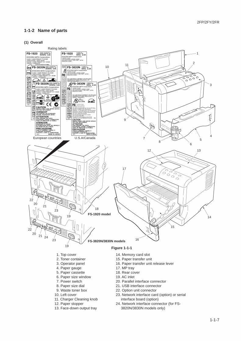
1-1 Specifications1-1-1 Specifications ....................................................................................................................................... 1-1-11-1-2 Name of parts ....................................................................................................................................... 1-1-7
(1) Overall ............................................................................................................................................ 1-1-7(2) Operator panel ................................................................................................................................ 1-1-8
1-1-3 Machine cross section .......................................................................................................................... 1-1-9
1-2 Handling Precautions1-2-1 Drum .................................................................................................................................................... 1-2-11-2-2 Installation environment ....................................................................................................................... 1-2-1
1-3 Installation1-3-1 Unpacking and installation ................................................................................................................... 1-3-1
(1) Installation procedure ..................................................................................................................... 1-3-11-3-2 Installing the optional expanding memory ............................................................................................ 1-3-81-3-3 Installing the optional memory card (CompactFlash) ......................................................................... 1-3-101-3-4 Installing the optional harddisk (Microdrive) ....................................................................................... 1-3-111-3-5 Installing the optional network interface card ..................................................................................... 1-3-12
1-4 Maintenance1-4-1 Service mode ....................................................................................................................................... 1-4-1
(1) Executing service mode ................................................................................................................. 1-4-11-4-2 Maintenance ....................................................................................................................................... 1-4-12
(1) Cleaning the paper transfer unit ................................................................................................... 1-4-12(2) Replacing the developer ............................................................................................................... 1-4-13
1-5 Troubleshooting1-5-1 Paper misfeed detection ...................................................................................................................... 1-5-1
(1) Paper misfeed indication ................................................................................................................ 1-5-1(2) Paper misfeed detection ................................................................................................................. 1-5-1
1-5-2 Self-diagnosis ....................................................................................................................................... 1-5-2(1) Self-diagnostic function .................................................................................................................. 1-5-2(2) Self-diagnostic indication ................................................................................................................ 1-5-2
1-5-3 Image formation problems ................................................................................................................... 1-5-15(1) Completely blank printout ............................................................................................................... 1-5-16(2) No image appears (entirely black). .................................................................................................. 1-5-16(3) Dropouts. ....................................................................................................................................... 1-5-17(4) Black dots. ..................................................................................................................................... 1-5-17(5) Black horizontal streaks. ................................................................................................................ 1-5-18(6) Black vertical streaks. ..................................................................................................................... 1-5-18(7) Unsharpness. ................................................................................................................................. 1-5-19(8) Gray background. ........................................................................................................................... 1-5-19(9) Dirt on the top edge or back of the paper. ....................................................................................... 1-5-20
(10) Undulated printing at the left edge (scanning start position). ............................................................ 1-5-201-5-4 Electrical problems .............................................................................................................................. 1-5-21
(1) Defective waste toner box detecting. .............................................................................................. 1-5-21(2) Defective paper jam detecting. ....................................................................................................... 1-5-21(3) Defective paper gauge sensing. ..................................................................................................... 1-5-21(4) Defective paper size detecting. ....................................................................................................... 1-5-22(5) Defective message displaying (LCD) [1] ......................................................................................... 1-5-22(6) Defective message displaying (LCD) [2] ......................................................................................... 1-5-22(7) Defective face up/down solenoid operating. .................................................................................... 1-5-23(8) False "Close paper transfer unit". ................................................................................................... 1-5-23(9) False "Close top cover". ................................................................................................................. 1-5-23
2FP/2FY2FR
1-5-5 Mechanical problems ........................................................................................................................... 1-5-24(1) No primary paper feed. ................................................................................................................... 1-5-24(2) No secondary paper feed. ............................................................................................................... 1-5-24(3) Skewed paper feed. ........................................................................................................................ 1-5-24(4) Multiple sheets of paper are fed at one time. .................................................................................... 1-5-24(5) Paper jams. .................................................................................................................................... 1-5-24(6) Abnormal noise is heard. ................................................................................................................ 1-5-24
1-6 Assembly and Disassembly1-6-1 Precautions for assembly and disassembly ......................................................................................... 1-6-1
(1) Precautions ..................................................................................................................................... 1-6-11-6-2 Removing the developer ...................................................................................................................... 1-6-2
(1) Removing the developer ................................................................................................................. 1-6-21-6-3 Removing the paper transfer unit ......................................................................................................... 1-6-41-6-4 Removing the main charger unit .......................................................................................................... 1-6-51-6-5 Removing the operator panel and outer covers ................................................................................... 1-6-6
(1) Removing the operator panel ......................................................................................................... 1-6-6(2) Removing the top cover/face-down output tray .............................................................................. 1-6-7(3) Removing the right cover ................................................................................................................ 1-6-8(4) Removing the left cover .................................................................................................................. 1-6-9
(1) Removing the MP tray paper feed unit ......................................................................................... 1-6-13(2) Removing the MP tray feed roller ............................................................................................... 1-6-14(3) Removing the retard holder (roller) .............................................................................................. 1-6-14
1-6-6 Removing the drum unit ..................................................................................................................... 1-6-101-6-7 Removing the pickup roller and feed roller ......................................................................................... 1-6-111-6-8 Removing the MP tray paper feed unit, MP tray feed roller and retard holder (roller) ....................... 1-6-13
1-6-9 Removing the transfer roller ............................................................................................................... 1-6-151-6-10 Removing the controller unit and the principal circuit board .............................................................. 1-6-16
(1) Removing and opening the controller unit .................................................................................... 1-6-16(2) Removing the engine board and power supply unit ..................................................................... 1-6-20(3) Removing the main board ............................................................................................................ 1-6-22(4) Removing the high voltage unit .................................................................................................... 1-6-23(5) Removing the sensor board ......................................................................................................... 1-6-24
1-6-11 Removing the drive unit and main motor ........................................................................................... 1-6-251-6-12 Removing and splitting the fuser unit ................................................................................................. 1-6-27
(1) Removing the separators ............................................................................................................. 1-6-30(2) Removing the heater lamp ........................................................................................................... 1-6-31(3) Removing the heat roller .............................................................................................................. 1-6-32(4) Removing the thermistor and thermal cutout ................................................................................ 1-6-33(5) Removing the press roller ............................................................................................................. 1-6-34
(1) Replacing the ozone filter B and ozone filter ............................................................................... 1-6-36
1-6-13 Removing the laser scanner unit ........................................................................................................ 1-6-351-6-14 Replacing the ozone filter B and ozone filter ...................................................................................... 1-6-36
1-7 Upgrading the Firmware1-7-1 Upgrading the firmware on the main board .......................................................................................... 1-7-1
(1) Firmware program data format ....................................................................................................... 1-7-2(2) Downloading the firmware from the parallel interface .................................................................... 1-7-3(3) Downloading the firmware from the memory card .......................................................................... 1-7-5(4) Downloading errors ........................................................................................................................ 1-7-7
2-1 Mechanical Construction2-1-1 Paper feeding system .......................................................................................................................... 2-1-1
(1) Paper feeding system ..................................................................................................................... 2-1-1(2) Paper feed control .......................................................................................................................... 2-1-2(3) Paper feeding mechanism .............................................................................................................. 2-1-3

2FP/2FY/2FR
2-2 Electrical Parts Layout2-2-1 Electrical parts layout ........................................................................................................................... 2-2-1
(1) Main frame (fuser, laser scanner unit, and controller unit) ............................................................. 2-2-1(2) Drum and developer ....................................................................................................................... 2-2-3
2-3 Operation of the PWBs2-3-1 Main board ........................................................................................................................................... 2-3-12-3-2 Engine board ........................................................................................................................................ 2-3-32-3-3 Power supply unit ................................................................................................................................. 2-3-8
2-4 AppendixesTiming chart No. 1 Paper cassette feeding, A4 size paper [For FS-1920/3820N models] ............................ 2-4-1Timing chart No. 2 Paper cassette feeding, Letter size paper [For FS-1920/3820N models] ....................... 2-4-2Timing chart No. 3 Paper cassette feeding, Legal size paper [For FS-1920/3820N models] ....................... 2-4-3Timing chart No. 4 MP tray feeding, A4 size paper [For FS-1920/3820N models] ....................................... 2-4-4Timing chart No. 5 MP tray feeding, A4 size paper [For FS-1920/3820N models] ....................................... 2-4-5Timing chart No. 6 MP tray feeding, A4 size paper [For FS-1920/3820N models] ....................................... 2-4-6Timing chart No. 7 Optional paper feeder feeding, A4 size paper [For FS-1920/3820N models] ................. 2-4-7Timing chart No. 8 Paper cassette feeding, A4 size paper [For FS-3830N model] ....................................... 2-4-8Timing chart No. 9 Paper cassette feeding, Letter size paper [For FS-3830N model] .................................. 2-4-9Timing chart No. 10 Paper cassette feeding, Legal size paper [For FS-3830N model] .............................. 2-4-10Timing chart No. 11 MP tray feeding, A4 size paper [For FS-3830N model] .............................................. 2-4-11Timing chart No. 12 MP tray feeding, A4 size paper [For FS-3830N model] .............................................. 2-4-12Timing chart No. 13 MP tray feeding, A4 size paper [For FS-3830N model] .............................................. 2-4-13Timing chart No. 14 Optional paper feeder feeding, A4 size paper [For FS-3830N model] ........................ 2-4-14Wiring diagram [For FS-1920 model] ........................................................................................................... 2-4-15Wiring diagram [For FS-3820N model] ......................................................................................................... 2-4-16Wiring diagram [For FS-3830N model] ......................................................................................................... 2-4-17Repetitive defects gauge .............................................................................................................................. 2-4-18
(4) Transfer ........................................................................................................................................ 2-1-16(5) Fusing ........................................................................................................................................... 2-1-17(6) Cleaning ....................................................................................................................................... 2-1-19
2-1-2 Electrophotographic cycle .................................................................................................................... 2-1-6(1) Main charging ................................................................................................................................. 2-1-7(2) Exposure ...................................................................................................................................... 2-1-10(3) Development ................................................................................................................................ 2-1-13

2FP/2FY2FR
This page is intentionally left blank.This page is intentionally left blank.

2FP/2FY/2FR-2
1-1-1
1-1-1 Specifications
FS-1920 model
Type ............................................... DesktopPrinting system .............................. Indirect electrostatic systemPaper type ...................................... Cassette: Plain paper (60 - 90 g/m2 [thick paper mode: 90 - 105 g/m2])
MP tray: Plain paper (60 - 90 g/m2 [thick paper mode: 90 - 200 g/m2])Special paper: Transparencies, letterhead, colored paper, recycled paperNote: Use the MP tray for special paper
Paper size ...................................... A4 (210 × 297 mm)B5 (182 × 257 mm)A5 (148 × 210 mm)Letter (81/2" × 11")Legal (81/2" × 14")Folio (210 × 330 mm)Non-standard size (148 to 215.9 mm × 210 to 355.6 mm: cassette), (148 to 215.9 mm × 210 to 355.6 mm: MP tray)
Printing speed ................................ [Cassette/MP tray ]: 28 pages//min. (A4, plain, 29 pages//min. (Letter, plain)[Duplexer DU-61]: 27 pages//min. (A4/Letter, plain)[Paper feeder PF-60]: 28 pages//min. (A4/Letter, plain)[Sorter SO-60]: 28 pages//min. (A4/Letter, plain)[Small size paper]: 18 pages/min. (A5, plain), 13 pages/min. (Post card)
First print ........................................ Approx. 9.5 s or less (A4/Letter), EcoFuser [OFF] and Ready, (room temperature23°C/73.4°F, humidity 60% RH) , depends on input dataApprox. 19.5 s or less (A4/Letter), EcoFuser [ON] or Sleep mode, (room temperature23°C/73.4°F, humidity 60% RH) , depends on input data
Warm-up time ................................. Approx. 10 s or less [from sleep mode]Approx. 18 s or less [from power on]
Paper feed system ......................... One universal cassette and one MP trayPaper loading capacity ................... Cassette: 500 sheets (80 g/m2, 0.11 µm)
MP tray: 100 sheets (80 g/m2, 0.11 µm)Paper eject system .........................Face down: 250 sheets (80 g/m2, 0.11 µm)
Face up: 250 sheets (80 g/m2, 0.11 µm)Face up: 100 sheets (80 g/m2, 0.11 µm), Optional paper tray PT-60
Standard memory ........................... 32 MB, expandable up to 288 MBAdditional memory ......................... 1 slot (16/32/64/128/256 MB DIMM)Resolution ...................................... Fast 1200 mode
600 × 600 dpi, with KIR (Kyocera Image Refinement)300 × 300 dpi, with KIR (Kyocera Image Refinement)
Photoconductor ............................. a-Si (drum diameter 30 mm)Charging system ............................ Single positive corona chargingDeveloping system ......................... Single element reversing processTransfer system ............................. Transfer rollerFixing system ................................. Heat roller
Heat source: Halogen heaters (750 W)Control temperature: 180°C/356°F (at normal ambient temperature)Abnormally high temperature protection device: thermal cutout
Charge erasing system .................. Exposure by eraser lamp (LED array)Cleaning system ............................ Cleaning bladeController hardware ....................... CPU: Power PC405 (266 MHz)
System ROM: 4 MB (32 Mbit × 1)Font ROM: 2 MB (16 Mbit × 1)Main RAM: 32 MB standard (on-board); expanding up to 288 MB (standard 32 MB +256 MB) at the maximum by adding optional expansion memoryOptional expansion RAM (DIMM): 1 slot

2FP/2FY/2FR-3
1-1-2
Controller software .......................... a) EmulationPCL6 (PCL5e+PCLXL)KPDL3 (PostScript 3 compatible)
b) Fonts:Bitmap font:1 Line Printer bitmap fontOutline fonts:35 PCL6 (PCL5e/PCL-XL) fonts45 KPDL2 fonts:
c) Graphic:(1) Raster graphic:
75, 100, 150, 200*, 300, 600* dpi(*200 dpi is supported when the resolution is 600 dpi.)
(2) Vector graphic:Line, Box, Circle, Arc, Fill pattern etc.
(3) Bar code:One-dimensional bar code: 45 typesTwo-dimensional bar code: 1 type (PDF-417)
d) ConnectivityPlug & play, Windows 95/98/Me/NT4.0/2000/XP
Interface ......................................... Parallel: High-speed (bi-directional), IEEE 1284 Nibble/ECP modeUSB: Full-Speed USB2.0Optional interface (KUIO-LV) × 1: Network interface card IB-20 (10 Base-TX/100Base-TX/10 Base-2), IB-21E (10 Base-TX/100 Base-TX), wireless LAN card IB-22must be installed.Optional serial interface: RS-232C (Max. 115.2 Kbps), Serial interface board IB-11must be installed.
Dimensions .................................... 345 (W)× 300 (H) × 390 (D) mm139/16" (W) × 1113/16" (H) × 181/4" (D)
Weight ............................................ Approx. 13.2 kg/299/16 lbsFloor requirements ......................... 496 (W) × 740 (D) mm
199/16" (W) × 293/16" (D)Power source ................................. 120 V AC, 60 Hz, 8.0 A
220 - 240 V AC, 50/60 Hz, 3.9 APower consumption ....................... Max.: 979 W (120 V AC), 987 W (220 - 240 V AC),
During printing: 422 W (120 V AC), 425 W (220 - 240 V AC)During sleep mode: 5.6 W (120 V AC), 5.3 W (220 - 240 V AC)
Noise .............................................. Printing: 55 dB(A)Ready: 33 dB(A)
Options ........................................... Paper feeder PF-60, Envelope feeder EF-60, Duplexer DU-61, Face-up tray PT-4 (forprinter), Face-up tray PT-60 (for duplexer), Sorter SO-60, Printer base unit PB-60,Additional memory (DIMM 16/32/64/128/256 MB), Memory card, Hard disk (IBMMicrodrive 340/512 MB/1 GB), Network interface card IB20/IB21E/IB-22, Serialinterface board IB-11

2FP/2FY/2FR-2
1-1-3
FS-3820N model
Type ............................................... DesktopPrinting system .............................. Indirect electrostatic systemPaper type ...................................... Cassette: Plain paper (60 - 90 g/m2 [thick paper mode: 90 - 105 g/m2])
MP tray: Plain paper (60 - 90 g/m2 [thick paper mode: 90 - 200 g/m2])Special paper: Transparencies, letterhead, colored paper, recycled paperNote: Use the MP tray for special paper
Paper size ...................................... A4 (210 × 297 mm)B5 (182 × 257 mm)A5 (148 × 210 mm)Letter (81/2" × 11")Legal (81/2" × 14")Folio (210 × 330 mm)Non-standard size (148 to 215.9 mm × 210 to 355.6 mm: cassette), (148 to 215.9 mm × 210 to 355.6 mm: MP tray)
Printing speed ................................ [Cassette/MP tray ]: 28 pages/min. (A4, plain), 29 pages/min. (Letter, plain)[Duplexer DU-61]: 27 pages/min. (A4/Letter, plain)[Paper feeder PF-8E]: 28 pages/min. (A4/Letter, plain)[Sorter SO-60]: 28 pages/min. (A4/Letter, plain)[Small size paper]: 20 pages/min. (A5, plain), 15 pages/min. (Post card)
First print ........................................ Approx. 9.5 s or less (A4/Letter), EcoFuser [OFF] and Ready, (room temperature23°C/73.4°F, humidity 60% RH) , depends on input dataApprox. 19.5 s or less (A4/Letter), EcoFuser [ON] or Sleep mode, (room temperature23°C/73.4°F, humidity 60% RH) , depends on input data
Warm-up time ................................. Approx. 10 s or less [from sleep mode]Approx. 18 s or less [from power on]
Paper feed system ......................... One universal cassette and one MP trayPaper loading capacity ................... Cassette: 500 sheets (80 g/m2, 0.11 µm)
MP tray: 100 sheets (80 g/m2, 0.11 µm)Paper eject system .........................Face down: 250 sheets (80 g/m2, 0.11 µm)
Face up: 250 sheets (80 g/m2, 0.11 µm)Face up: 100 sheets (80 g/m2, 0.11 µm), Optional paper tray PT-60
Standard memory ........................... 64 MB, expandable up to 320 MBAdditional memory ......................... 1 slot (16/32/64/128/256 MB DIMM)Resolution ...................................... Fast 1200 mode
600 × 600 dpi, with KIR (Kyocera Image Refinement)300 × 300 dpi, with KIR (Kyocera Image Refinement)
Photoconductor .............................. a-Si (drum diameter 30 mm)Charging system ............................ Single positive corona chargingDeveloping system ......................... Single element reversing processTransfer system ............................. Transfer rollerFixing system ................................. Heat roller
Heat source: Halogen heaters (750 W)Control temperature: 180°C/356°F (at normal ambient temperature)Abnormally high temperature protection device: thermal cutout
Charge erasing system .................. Exposure by eraser lamp (LED array)Cleaning system ............................ Cleaning bladeController hardware ....................... CPU: Power PC750CXe (300 MHz)
System ROM: 4 MB (16 Mbit × 2)Font ROM: 2 MB (16 Mbit × 1)Main RAM: [Standard] 64 MB (on-board); [Expanding] up to 320 MB (64 MB + 256MB × 1) at the maximum by adding optional expansion memoryOptional expansion RAM (DIMM): 1 slot

2FP/2FY/2FR-3
1-1-4
Controller software .......................... a) EmulationPCL6 (PCL5e+PCLXL)KPDL3 (PostScript 3 compatible)
b) Fonts:Bitmap font:1 Line Printer bitmap fontOutline fonts:35 PCL6 (PCL5e/PCL-XL) fonts45 KPDL2 fonts:
c) Graphic:(1) Raster graphic:
75, 100, 150, 200*, 300, 600* dpi(*200 dpi is supported when the resolution is 600 dpi.)
(2) Vector graphic:Line, Box, Circle, Arc, Fill pattern etc.
(3) Bar code:One-dimensional bar code: 45 typesTwo-dimensional bar code: 1 type (PDF-417)
d) ConnectivityPlug & play, Windows 95/98/Me/NT4.0/2000/XP
Interface ......................................... Parallel: High-speed (bi-directional), IEEE 1284 Nibble/ECP modeUSB: Hi-Speed USB 2.0 (480 Mbps)/Full-Speed USB 2.0 (12 Mbps)Network: Protocol support TCP/IP, IPX/SPX, NetBEUI, EtherTalkOptional interface (KUIO-LV) × 1: Network interface card IB-20 (10 Base-TX/100Base-TX/10 Base-2), IB-21E (10 Base-TX/100 Base-TX), wireless LAN card IB-22must be installed.Optional serial interface: RS-232C (Max. 115.2 Kbps), Serial interface board IB-11must be installed.
Dimensions .................................... 345 (W)× 300 (H) × 390 (D) mm139/16" (W) × 1113/16" (H) × 181/4" (D)
Weight ............................................ Approx. 13.2 kg/299/16 lbsFloor requirements .......................... 496 (W) × 740 (D) mm
199/16" (W) × 293/16" (D)Power source ................................. 120 V AC, 60 Hz, 8.0 A
220 - 240 V AC, 50/60 Hz, 4.0 APower consumption ........................ Max.: 1008 W
During printing: 425 WDuring sleep mode: 13 W
Noise .............................................. Printing: 55 dB(A)Ready: 33 dB(A)
Options ........................................... Paper feeder PF-60, Envelope feeder EF-60, Duplexer DU-61, Face-up tray PT-4 (forprinter), Face-up tray PT-60 (for duplexer), Sorter SO-60, Printer base unit PB-60,Additional memory (DIMM 16/32/64/128/256 MB), Memory card, Hard disk (IBMMicrodrive 340/512 MB/1 GB), Network interface card IB20/IB21E/IB-22, Serialinterface board IB-11

2FP/2FY/2FR-3
1-1-5
FS-3830N model
Type ............................................... DesktopPrinting system .............................. Indirect electrostatic systemPaper type ...................................... Cassette: Plain paper (60 - 90 g/m2 [thick paper mode: 90 - 105 g/m2])
MP tray: Plain paper (60 - 90 g/m2 [thick paper mode: 90 - 200 g/m2])Special paper: Transparencies, letterhead, colored paper, recycled paperNote: Use the MP tray for special paper
Paper size ...................................... A4 (210 × 297 mm)B5 (182 × 257 mm)A5 (148 × 210 mm)Letter (81/2" × 11")Legal (81/2" × 14")Folio (210 × 330 mm)Non-standard size (148 to 215.9 mm × 210 to 355.6 mm: cassette), (148 to 215.9 mm × 210 to 355.6 mm: MP tray)
Printing speed ................................. [Cassette/MP tray ]: 33 pages/min. (A4, plain), 35 pages/min. (Letter, plain)[Duplexer DU-61]: 30 pages/min. (A4/Letter, plain)[Paper feeder PF-8E]: 31 pages/min. (A4/Letter, plain)[Sorter SO-60]: 28 pages/min. (A4/Letter, plain)[Small size paper]: 20 pages/min. (A5, plain), 15 pages/min. (Post card)
First print ........................................ Approx. 11.5 s or less (A4/Letter), EcoFuser [OFF] and Ready, (room temperature23°C/73.4°F, humidity 60% RH) , depends on input dataApprox. 26.5 s or less (A4/Letter), EcoFuser [ON] or Sleep mode, (room temperature23°C/73.4°F, humidity 60% RH) , depends on input data
Warm-up time ................................. Approx. 15 s or less [from sleep mode]Approx. 20 s or less [from power on]
Paper feed system ......................... One universal cassette and one MP trayPaper loading capacity ................... Cassette: 500 sheets (80 g/m2, 0.11 µm)
MP tray: 100 sheets (80 g/m2, 0.11 µm)Paper eject system .........................Face down: 250 sheets (80 g/m2, 0.11 µm)
Face up: 250 sheets (80 g/m2, 0.11 µm)Face up: 100 sheets (80 g/m2, 0.11 µm), Optional paper tray PT-60
Standard memory ........................... 96 MB, expandable up to 576 MBAdditional memory ......................... 2 slots (16/32/64/128/256 MB DIMM)Resolution ...................................... Fast 1200 mode
600 × 600 dpi, with KIR (Kyocera Image Refinement)300 × 300 dpi, with KIR (Kyocera Image Refinement)
Photoconductor .............................. a-Si (drum diameter 30 mm)Charging system ............................ Single positive corona chargingDeveloping system ......................... Single element reversing processTransfer system ............................. Transfer rollerFixing system ................................. Heat roller
Heat source: Halogen heaters (750 W)Control temperature: 180°C/356°F (at normal ambient temperature)Abnormally high temperature protection device: thermal cutout
Charge erasing system .................. Exposure by eraser lamp (LED array)Cleaning system ............................ Cleaning bladeController hardware ....................... CPU: Power PC750CXe (300 MHz)
System ROM: 4 MB (16 Mbit × 2)Font ROM: 2 MB (16 Mbit × 1)Main RAM: [Standard] 64 MB (on-board) + 32 MB DIMM; [Expanding] up to 576 MB(64 MB + 256 MB × 2) at the maximum by adding optional expansion memoryOptional expansion RAM (DIMM): 2 slots

2FP/2FY/2FR-3
1-1-6
Controller software .......................... a) EmulationPCL6 (PCL5e+PCLXL)KPDL3 (PostScript 3 compatible)
b) Fonts:Bitmap font:1 Line Printer bitmap fontOutline fonts:35 PCL6 (PCL5e/PCL-XL) fonts45 KPDL2 fonts:
c) Graphic:(1) Raster graphic:
75, 100, 150, 200*, 300, 600* dpi(*200 dpi is supported when the resolution is 600 dpi.)
(2) Vector graphic:Line, Box, Circle, Arc, Fill pattern etc.
(3) Bar code:One-dimensional bar code: 45 typesTwo-dimensional bar code: 1 type (PDF-417)
d) ConnectivityPlug & play, Windows 95/98/Me/NT4.0/2000/XP
Interface ......................................... Parallel: High-speed (bi-directional), IEEE 1284 Nibble/ECP modeUSB: Hi-Speed USB 2.0 (480 Mbps)/Full-Speed USB 2.0 (12 Mbps)Network: Protocol support TCP/IP, IPX/SPX, NetBEUI, EtherTalkOptional interface (KUIO-LV) × 1: Network interface card IB-20 (10 Base-TX/100Base-TX/10 Base-2), IB-21E (10 Base-TX/100 Base-TX), wireless LAN card IB-22must be installed.Optional serial interface: RS-232C (Max. 115.2 Kbps), Serial interface board IB-11must be installed.
Dimensions .................................... 345 (W)× 300 (H) × 390 (D) mm139/16" (W) × 1113/16" (H) × 181/4" (D)
Weight ............................................ Approx. 13.2 kg/299/16 lbsFloor requirements ......................... 496 (W) × 740 (D) mm
199/16" (W) × 293/16" (D)Power source ................................. 120 V AC, 60 Hz, 8.0 A
220 - 240 V AC, 50/60 Hz, 4.0 APower consumption ....................... Max.: 1008 W
During sleep mode: 512 WDuring sleep mode: 13 W
Noise .............................................. Printing: 57 dB(A)Ready: 36 dB(A)
Options ........................................... Paper feeder PF-60, Envelope feeder EF-60, Duplexer DU-61, Face-up tray PT-4 (forprinter), Face-up tray PT-60 (for duplexer), Sorter SO-60, Printer base unit PB-60,Additional memory (DIMM 16/32/64/128/256 MB), Memory card, Hard disk (IBMMicrodrive 340/512 MB/1 GB), Network interface card IB20/IB21E/IB-22, Serialinterface board IB-11
2FP/2FY/2FR
1-1-7
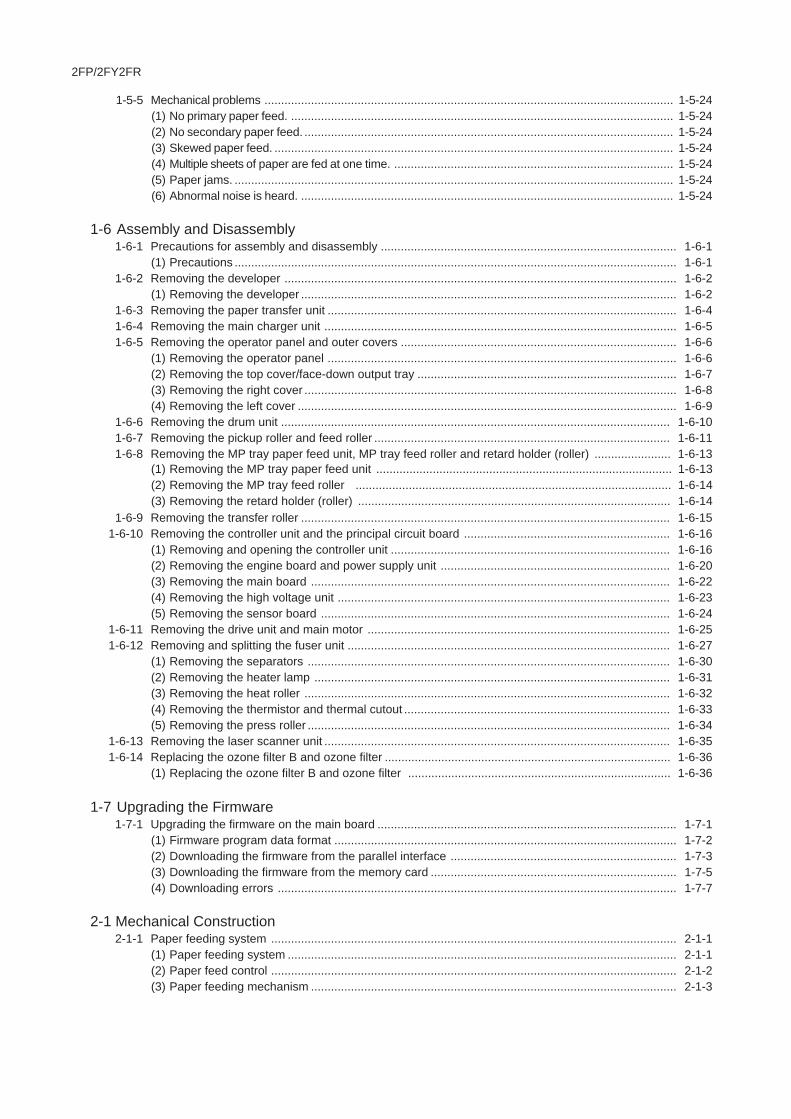
1-1-2 Name of parts
(1) Overall
Figure 1-1-1
1. Top cover 2. Toner container 3. Operator panel 4. Paper gauge 5. Paper cassette 6. Paper size window 7. Power switch 8. Paper size dial 9. Waste toner box10. Left cover11. Charger Cleaning knob12. Paper stopper13. Face-down output tray
14. Memory card slot15. Paper transfer unit16. Paper transfer unit release lever17. MP tray18. Rear cover19. AC inlet20. Parallel interface connector21. USB interface connector22. Option unit connector23. Network interface card (option) or serial
interface board (option)24. Network interface connector (for FS-
3820N/3830N models only)
1
10 11
9
87
15
17
1823
2021
22
19
13
14
2
3
23
20 21 24
22
19
FS-1920 model
FS-3820N/3830N models
6
16
54
Rating labels
U.S.A/CanadaEuropean countries
12
2FP/2FY/2FR
1-1-8
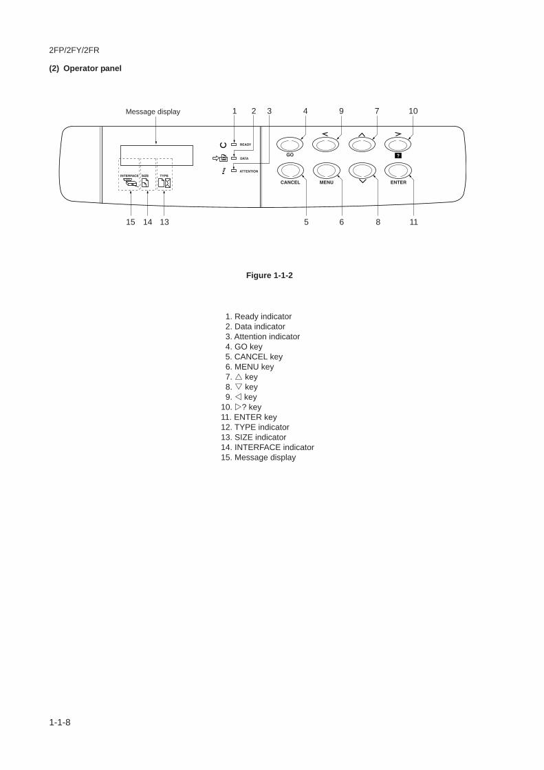
(2) Operator panel
1. Ready indicator 2. Data indicator 3. Attention indicator 4. GO key 5. CANCEL key 6. MENU key 7. key 8. key 9. key10. ? key11. ENTER key12. TYPE indicator13. SIZE indicator14. INTERFACE indicator15. Message display
Figure 1-1-2
Message display 3 94 7 1021
6 8 11515 14 13
2FP/2FY/2FR
1-1-9
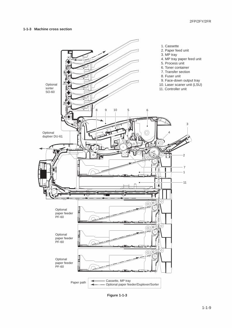
Cassette, MP tray
Optional paper feeder/Duplexer/SorterPaper path
Optional
duplxer DU-61
Optional
sorter
SO-60
Optional
paper feeder
PF-60
Optional
paper feeder
PF-60
Optional
paper feeder
PF-60
1
11
7
2
3
6
4
1098 5
1-1-3 Machine cross section
1. Cassette 2. Paper feed unit 3. MP tray 4. MP tray paper feed unit 5. Process unit 6. Toner container 7. Transfer section 8. Fuser unit 9. Face-down output tray10. Laser scaner unit (LSU)11. Controller unit
Figure 1-1-3

2FP/2FY/2FR
1-1-10
This page is intentionally left blank.

2FP/2FY/2FR
1-2-1
1-2-1 DrumNote the following when handling or storing the drum.• When removing the process unit, never expose the drum surface to strong direct light.• Keep the drum at an ambient temperature between 10°C/50°F and 32.5°C/90.5°F and at a relative humidity not higher
than 80% RH. Avoid abrupt changes in temperature and humidity.• Avoid exposure to any substance which is harmful to or may affect the quality of the drum.• Do not touch the drum surface with any object. Should it be touched by hands or stained with oil, clean it.
1-2-2 Installation environment
1. Temperature: 10 - 32.5°C/50 - 90.5°F 2. Humidity: 20 - 80%RH 3. Power supply: 120 V AC, 7.1 A
220 - 240 V AC, 3.8 A 4. Power source frequency: 50 Hz ±0.3%/60 Hz ±0.3% 5. Installation location• Avoid direct sunlight or bright lighting. Ensure that the photoconductor will not be exposed to direct sunlight or other
strong light when removing paper jams.Avoid extremes of temperature and humidity, abrupt ambient temperature changes, and hot or cold air directed onto themachine.
• Avoid dust and vibration.• Choose a surface capable of supporting the weight of the machine.• Place the machine on a level surface (maximum allowance inclination: 1°).• Avoid air-borne substances that may adversely affect the machine or degrade the photoconductor, such as
mercury, acidic of alkaline vapors, inorganic gasses, NOx, SOx gases and chlorine-based organic solvents. Select aroom with good ventilation.
6. Allow sufficient access for proper operation and maintenance of the machine.Machine front: 50 mm/1911/16" Machine rear: 40 mm/153/4"Machine right: 25 mm/97/8" Machine left: 25 mm/97/8"Machine above: 30 mm/1113/16"
a
b c
a: 300 mm/143/4"b: 345 mm/147/8"c: 390 mm/91/4"
Figure 1-2-1 Installation dimensions

2FP/2FY/2FR
1-2-2
This page is intentionally left blank.

1-3-1
2FP/2FY/2FR
1-3-1 Unpacking and installation
(1) Installation procedure
Unpacking.
Installing the toner container.
Installing the waste toner box.
Loading paper.
Installing the dust cover.
Start
Connect the printer cable and power cord.
Initializing the printer and make test page.
Completion of the machine installation.

1-3-2
2FP/2FY/2FR
1
2 4
3
5
6
7
8
12
3
[For U.S.A model only]
87
5 6
4
Unpack.
1. Printer 2. Waste toner box 3. Toner container 4. Power cord 5. CD-ROMs 6. Installation guide and other printed matter 7. Plastic bag for developer 8. Dust cover [For U.S.A model only]
Figure 1-3-1 Unpacking

1-3-3
2FP/2FY/2FR
1. With the label side down, thoroughly shake thetoner container (in the direction of the arrow) tentimes or more to loosen and mix the toner inside.
Installing the toner container.
Figure 1-3-2
Figure 1-3-4
Toner container
2. Carefully remove the protective seal.
Protective seal
Figure 1-3-3
Top cover Toner container 3. Open the printer top cover all the way. 4. Install the toner container into the printer.

1-3-4
2FP/2FY/2FR
Figure 1-3-5
5. Push firmly on the top of the toner container atthe positions marked PUSH HERE.
6. Close the top cover.
Figure 1-3-6
Figure 1-3-7
Toner container
Top cover
Install the waste toner box.
Waste toner box
Cap
Left cover
Waste toner box
1. Open the cap of the waste toner box.
2. Open the left cover on the left side of the printer. 3. Insert the waste toner box as shown in the figure.
The box will be locked when it fits into place.
1-3-5
2FP/2FY/2FR
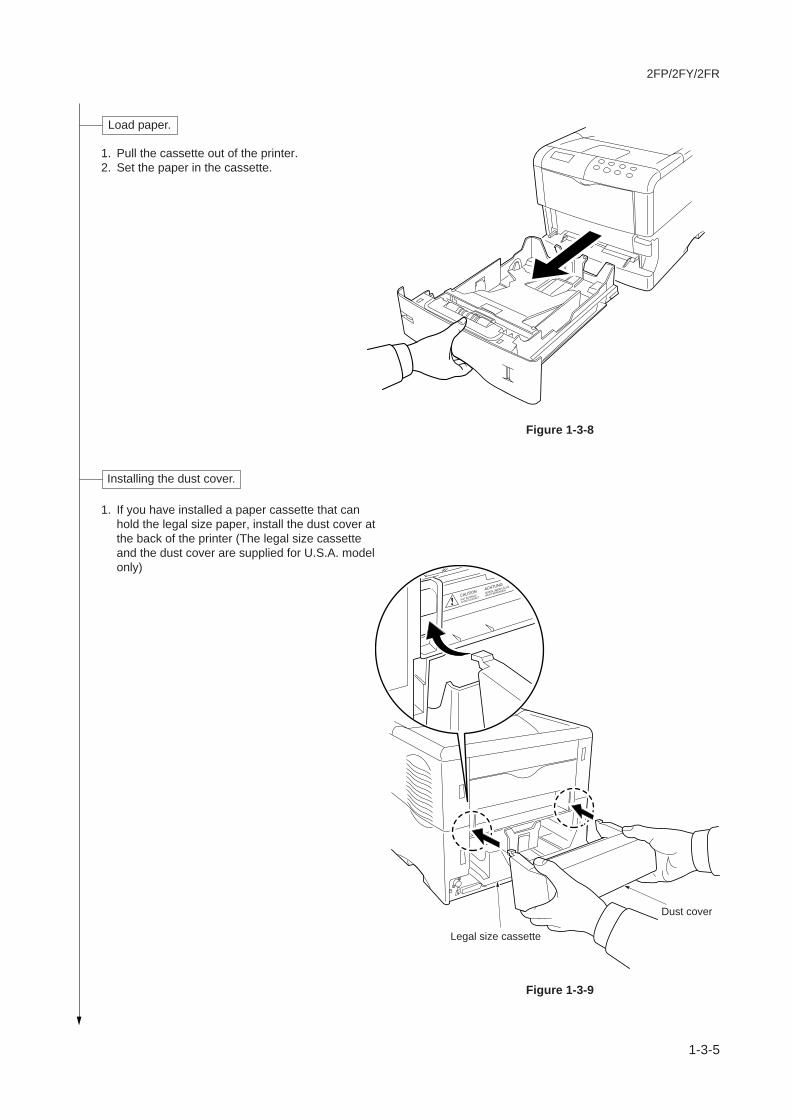
Figure 1-3-8
1. Pull the cassette out of the printer. 2. Set the paper in the cassette.
Figure 1-3-9
Load paper.
1. If you have installed a paper cassette that canhold the legal size paper, install the dust cover atthe back of the printer (The legal size cassetteand the dust cover are supplied for U.S.A. modelonly)
Dust cover
Legal size cassette
Installing the dust cover.

1-3-6
2FP/2FY/2FR
1. Connect the printer cable (parallel, USB ornetwork* interface).*: For FS-3820N/3830N models only.
Figure 1-3-11
Connect the printer cable and power cord.
Figure 1-3-10
Paprallelcable
USB cable
Network(ether)cable
Parallel
USBNetwork*
*: FS-3820N/3830Nmodels only
2. Connect the power cord to AC inlet.
Power cord
AC inlet

1-3-7
2FP/2FY/2FR
1. Turn on the printer's power switch. The messagedisplay should indicate [Self test].When the printer is first switched on afterinstallation, there will be a delay of approximately8 minutes before the printer gets ready to print asthe developer needs to be filled with toner. Duringthis period, the message display shows [Pleasewait (Adding toner)].
2. Wait until the READY indicator is also lit and themessage display indicates [Ready]. The printer isready to print.
3. The printer can print two different types of statuspage standard and service-purpose. A service-purpose status page contains more detailedinformation about printer settings than a standardstatus page.
To print standard status page(1) Press the MENU key on the operator panel.(2) Press the or key repeatedly until the
message display shows [>>Print Status Page].(3) Press the ENTER key twice. The message
display indicates [Processing] during printing ofthe standard status page, then returns to[Ready].
To print service status page(1) Press the MENU key on the operator panel.(2) Press the or key repeatedly until the
message display shows [Others >].(3) Press the key.(4) Press the or key repeatedly until the
message display shows [>Service >].(5) Press the key.(6) Press the or key repeatedly until the
message display shows [>>Print Status Page].(7) Press the ENTER key twice. The message
display indicates [Processing] during printing ofthe service status page, then returns to [Ready].
Initializing the printer and make test print.
Completion of machine installation.

1-3-8
2FP/2FY/2FR
1-3-2 Installing the optional expanding memory
The main board of the printer is equipped with one socket for memory expansion. Expansion memory is available in the formof DIMM (Dual In-line Memory Module).
CAUTIONTake precautions that no foreign substances such as metalchips or liquid get inside the printer during the installationprocess. Operation of the printer during the presence of aforeign substance may lead to fire or electric shock.
WARNINGTurn the printer's power switch off. Unplug the printer'spower cable.
Procedure 1. Remove the two screws and then pull the main board
all the way out of the printer.There are two DIMM sockets are provided on the FS-3830N model, and one DIMM socket on the FS-1920/3820N models for expanding the printer's memory.(The extra 32 MB of DIMM memory that comestandard with the FS-3830N model is installed in oneof the expanding DIMM sockets.)
Memory card slot
Memory card
Screw
Screw
One DIMM socket
One DIMM socket
FS-3820N model
Standard 32 MBDIMM memory installed
FS-1920 model
Two DIMM sockets
FS-3830N model
Figure 1-3-12 Removing the main board

1-3-9
2FP/2FY/2FR
Figure 1-3-13 Inserting the DIMM
2. Open the clips on both ends of the DIMM socket. 3. Insert the DIMM into the DIMM socket so that the
notches on the DIMM align with the correspondingprotrusions in the slot.
4. Close the clips on the DIMM slot to secure theDIMM.
DIMM memory
Clip
Clip
DIMM socket

1-3-10
2FP/2FY/2FR
1-3-3 Installing the optional memory card (CompactFlash)
The main board of the printer is equipped with oneslot for memory card.
CAUTIONTake precautions that no foreign substances such asmetal chips or liquid get inside the printer during theinstallation process. Operation of the printer during thepresence of a foreign substance may lead to fire orelectric shock.
WARNINGTurn the printer's power switch off. Unplug the printer'spower cable and disconnect the printer from thecomputer or the network. Never insert or remove amemory card while the printer power is ON.
Failure to turn the power switch OFF will immediatelyhalt the printer with a [Memory card err20] message(this message may not always appear). It also couldresult in any damage to the printer's electronic parts orthe memory card. Turn the power switch ON again torestart the printer.
Procedure 1. Turn the power switch off. 2. Insert the memory card in the memory card slot at
the right bottom of the printer. Insert it face up,connector end first. Push it in all the way.
Figure 1-3-14 Inserting the memory card
Memory card
Memory cardslot
1-3-11
2FP/2FY/2FR
FS-3820N/3830N models
FS-1920 model
Harddisk socket
Harddisk socket
Main board
Main board
Harddisk (Microdrive)
Harddisk (Microdrive)
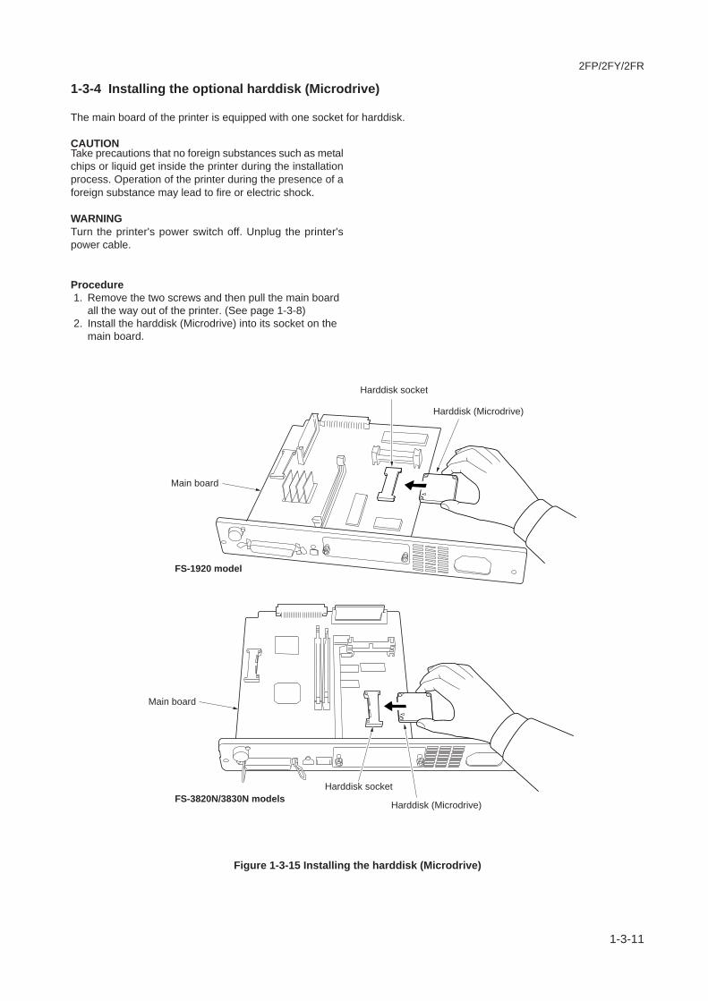
1-3-4 Installing the optional harddisk (Microdrive)
The main board of the printer is equipped with one socket for harddisk.
CAUTIONTake precautions that no foreign substances such as metalchips or liquid get inside the printer during the installationprocess. Operation of the printer during the presence of aforeign substance may lead to fire or electric shock.
WARNINGTurn the printer's power switch off. Unplug the printer'spower cable.
Procedure 1. Remove the two screws and then pull the main board
all the way out of the printer. (See page 1-3-8) 2. Install the harddisk (Microdrive) into its socket on the
main board.
Figure 1-3-15 Installing the harddisk (Microdrive)

1-3-12
2FP/2FY/2FR
1-3-5 Installing the optional network interface card
The main board of the printer is equipped with a network interface card slot (KUIO-LV type, 3.3 V).If the serial interface board kit is installed, remove it to use the network interface card.
Figure 1-3-16 Installing the optional network interface card
CAUTIONTake precautions that no foreign substances such asmetal chips or liquid get inside the printer during theinstallation process. Operation of the printer during thepresence of a foreign substance may lead to fire orelectric shock.
WARNINGTurn the printer's power switch off. Unplug the printer'spower cable.
Procedure 1. Turn the power switch off. 2. Remove the two screws then remove the option
interface card slot cover. 3. Insert the network interface card to the option
interface card slot. 4. Fix the network interface card by two screws. 5. Connect the network cable to the network interface
card. 6. Set the network address from the printer operator
panel. (Refer to the printer's user's manual)
Option interface slot cover
Option interface slot
Network interface card
Network interface card
Network (ether) cable
Screws

2FP/2FY/2FR-4
1-4-1
1-4-1 Service mode
The printer is equipped with the service mode that can be accessed in the menu system. The service mode is intendedfor use by the service person for maintenance and service for the items explained in the following sections.
(1) Executing service mode
Ready
––– A4 PLAIN
1. Press the MENU key.
Message display
To print a status page for service purpose.See page 1-4-2.
2. Press the q or p key several times until [Others >] is displayed.
Menu Map
Status Page
Service mode items
3. Press the u key.
5. Press the u key.
To performing a drum refreshing.See page 1-4-11.
>>DRUM-CTRL
00
Event Log
>>Developer
To performing a automatic drum refreshing.See page 1-4-11.
To initial setting for the developer.See page 1-4-10.
To print an event log (EVENT LOG)(Displayed when FRPO I1 is set to 1)See page 1-4-6.
To reset the counter after replacing the maintenance kit.See page 1-4-9.
>>Maintenance
>>Drum
>MSG Language
English
Others >
4. Press the q or p key several times until [>Service >] is displayed.
>Service >
To scrollthese items,press theq or p keyrepeatedly.

2FP/2FY/2FR-6
1-4-2
Service items Description
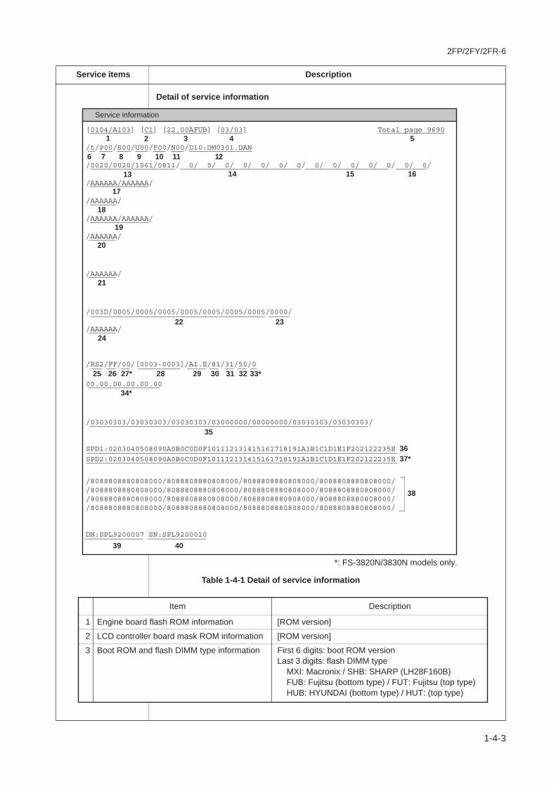
Printing a status page for service purposeDescriptionService information on the status page include various settings for the printer, servicestatistics, etc.PurposeTo understand the machine environments and general settings.Method1. Enter the service mode [>>Printing Status Page].2. Press the Enter key. [?] will be displayed.3. Press the Enter key. The status page is printed. (See the figure below)
Figure 1-4-1
Status Page
Firmware version: Released: Jan/9/2004
Controller firmware version Released date of the firmware
Service information (See the next page.)
Service information[0104/A103] [C1] [22.00AFUB] [03/03] Total page 9690
/t/P00/S00/U00/F00/N00/D10:DM0301.DAN
/0020/0020/1061/0811/ 0/ 0/ 0/ 0/ 0/ 0/ 0/ 0/ 0/ 0/ 0/ 0/ 0/ 0//AAAAAA/AAAAAA//AAAAAA//AAAAAA/AAAAAA//AAAAAA/
/AAAAAA/
/003D/0005/0005/0005/0005/0005/0005/0005/0000/
/RS2/FF/00/0003-0003]/AI.E/81/31/50/000.00.00.00.00.00
/03030303/03030303/03030303/03000000/00000000/03030303/03030303/
SPD1:0203040508090A0B0C0D0F101112131415161718191A1B1C1D1E1F202122235ESPD2:0203040508090A0B0C0D0F101112131415161718191A1B1C1D1E1F202122235E
/8088808880808000/8088808880808000/8088808880808000/8088808880808000//8088808880808000/8088808880808000/8088808880808000/8088808880808000//8088808880808000/8088808880808000/8088808880808000/8088808880808000//8088808880808000/8088808880808000/8088808880808000/8088808880808000/
DN:SPL9200007 SN:SPL9200010
2FP/2FY/2FR-6
1-4-3
Service items Description
Detail of service information
Item Description
1 Engine board flash ROM information [ROM version]
2 LCD controller board mask ROM information [ROM version]
3 Boot ROM and flash DIMM type information First 6 digits: boot ROM versionLast 3 digits: flash DIMM type MXI: Macronix / SHB: SHARP (LH28F160B) FUB: Fujitsu (bottom type) / FUT: Fujitsu (top type) HUB: HYUNDAI (bottom type) / HUT: (top type)
[0104/A103] [C1] [22.00AFUB] [03/03] Total page 9690
/t/P00/S00/U00/F00/N00/D10:DM0301.DAN
/0020/0020/1061/0811/ 0/ 0/ 0/ 0/ 0/ 0/ 0/ 0/ 0/ 0/ 0/ 0/ 0/ 0/
/AAAAAA/AAAAAA/
/AAAAAA/
/AAAAAA/AAAAAA/
/AAAAAA/
/AAAAAA/
/003D/0005/0005/0005/0005/0005/0005/0005/0000/
/RS2/FF/00/[0003-0003]/AI.E/81/31/50/0
/03030303/03030303/03030303/03000000/00000000/03030303/03030303/
SPD1:0203040508090A0B0C0D0F101112131415161718191A1B1C1D1E1F202122235E
/8088808880808000/8088808880808000/8088808880808000/8088808880808000//8088808880808000/8088808880808000/8088808880808000/8088808880808000//8088808880808000/8088808880808000/8088808880808000/8088808880808000//8088808880808000/8088808880808000/8088808880808000/8088808880808000/
DN:SPL9200007 SN:SPL9200010
1
17
19
20
21
18
8 9 10 11 12
14 15 1613
2 3 4 5
7
22 23
25 26 27* 28 29 30 31 32 33*
35
36
38
39
/AAAAAA/24
00.00.00.00.00.0034*
40
Service information
SPD2:0203040508090A0B0C0D0F101112131415161718191A1B1C1D1E1F202122235E 37*
6
Table 1-4-1 Detail of service information
*: FS-3820N/3830N models only.
2FP/2FY/2FR-6
1-4-4
Service items Description
Item Description
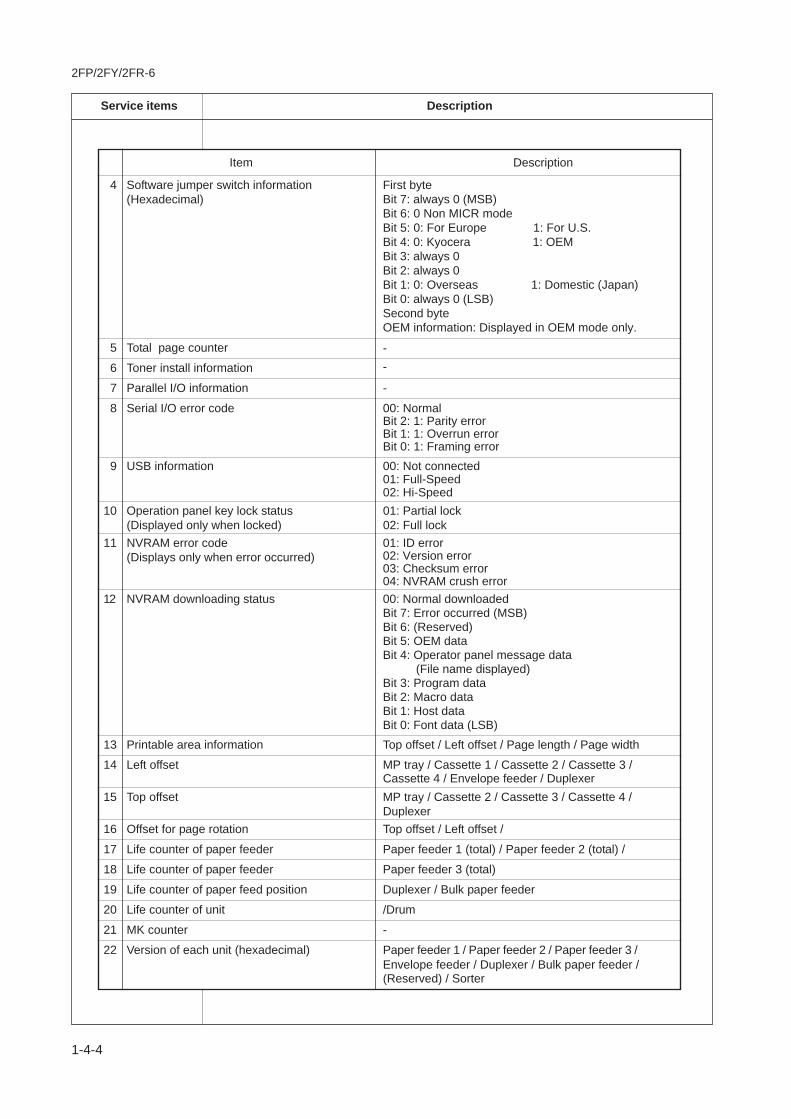
4 Software jumper switch information First byte (Hexadecimal) Bit 7: always 0 (MSB)
Bit 6: 0 Non MICR modeBit 5: 0: For Europe 1: For U.S.Bit 4: 0: Kyocera 1: OEMBit 3: always 0Bit 2: always 0Bit 1: 0: Overseas 1: Domestic (Japan)Bit 0: always 0 (LSB)Second byteOEM information: Displayed in OEM mode only.
5 Total page counter
6 Toner install information
7 Parallel I/O information
8 Serial I/O error code 00: NormalBit 2: 1: Parity errorBit 1: 1: Overrun errorBit 0: 1: Framing error
9 USB information 00: Not connected01: Full-Speed02: Hi-Speed
10 Operation panel key lock status 01: Partial lock(Displayed only when locked) 02: Full lock
11 NVRAM error code 01: ID error(Displays only when error occurred) 02: Version error
03: Checksum error04: NVRAM crush error
12 NVRAM downloading status 00: Normal downloadedBit 7: Error occurred (MSB)Bit 6: (Reserved)Bit 5: OEM dataBit 4: Operator panel message data (File name displayed)Bit 3: Program dataBit 2: Macro dataBit 1: Host dataBit 0: Font data (LSB)
13 Printable area information Top offset / Left offset / Page length / Page width
14 Left offset MP tray / Cassette 1 / Cassette 2 / Cassette 3 /Cassette 4 / Envelope feeder / Duplexer
15 Top offset MP tray / Cassette 2 / Cassette 3 / Cassette 4 /Duplexer
16 Offset for page rotation Top offset / Left offset /
17 Life counter of paper feeder Paper feeder 1 (total) / Paper feeder 2 (total) /
18 Life counter of paper feeder Paper feeder 3 (total)
19 Life counter of paper feed position Duplexer / Bulk paper feeder
20 Life counter of unit /Drum
21 MK counter -
--
-
22 Version of each unit (hexadecimal) Paper feeder 1 / Paper feeder 2 / Paper feeder 3 /Envelope feeder / Duplexer / Bulk paper feeder /(Reserved) / Sorter

2FP/2FY/2FR-6
1-4-5
Service items Description
Item Description
23 EEPROM error of each unit Bit 0: Ppaer feeder 1(Hexadecimal) Bit 1: Paper feeder 2
Bit 2: Paper feeder 3Bit 3: DuplexerBit 4: SorterBit 5: Bulk paper feederBit 6: (Reserved)Bit 7: Drum
25 Serial interface information RS2: RS-232C
24 Drum ID -
26 Drum sensitivity information -
Setting value (FRPO I4), Hexadecimal 27* Calibration table settings
28 Optional paper feeder information First 2 bytes
Bit 2 to 6: Paper feeder 1 to 5 (4 and 5 Reserved)Bit 1: Cassette 1Bit 0: MP tray
Bit 7: DuplexerBit 8: Bulk paper feederBit 9: Envelope feederBit 10 to 15: (Reserved)Second 2 bytesBit 0: Face-upBit 1: Face-downBit 2: (Reserved)Bit 3: SorterBit 4 to 15: (Reserved)
29 Average print density (%) 2 digits of integer part and 1 digit of fraction part(total print density from shipping from factory)
30 Operation panel message language PMSG command setting value (decimal)
31 Current temperature 0 to 80 °C("-" = Humidity/temperature sensor is abnormal.)
32 Current humidity 5 to 100 %RH (in 1% increment)
34* MAC address -
2 to 6 bytes, 8 to 36 bytes, 94 to 95 bytes (total 32 bytes)
2 to 6 bytes, 8 to 36 bytes, 94 to 95 bytes (total 32 bytes)
-
-
-
33* Number of rebooting for vertical distortioncheck
-
35 Media type attributes Media type 1 to 28 (14 to 20: Reserved)
36 SPD information (slot 1)
37* SPD information (slot 2)
38 Engine parameter setting
39 Drum serial number
40 Machine serial number
*1: FS-3820N/3830N models only.
2FP/2FY/2FR-5
1-4-6
Service items Description
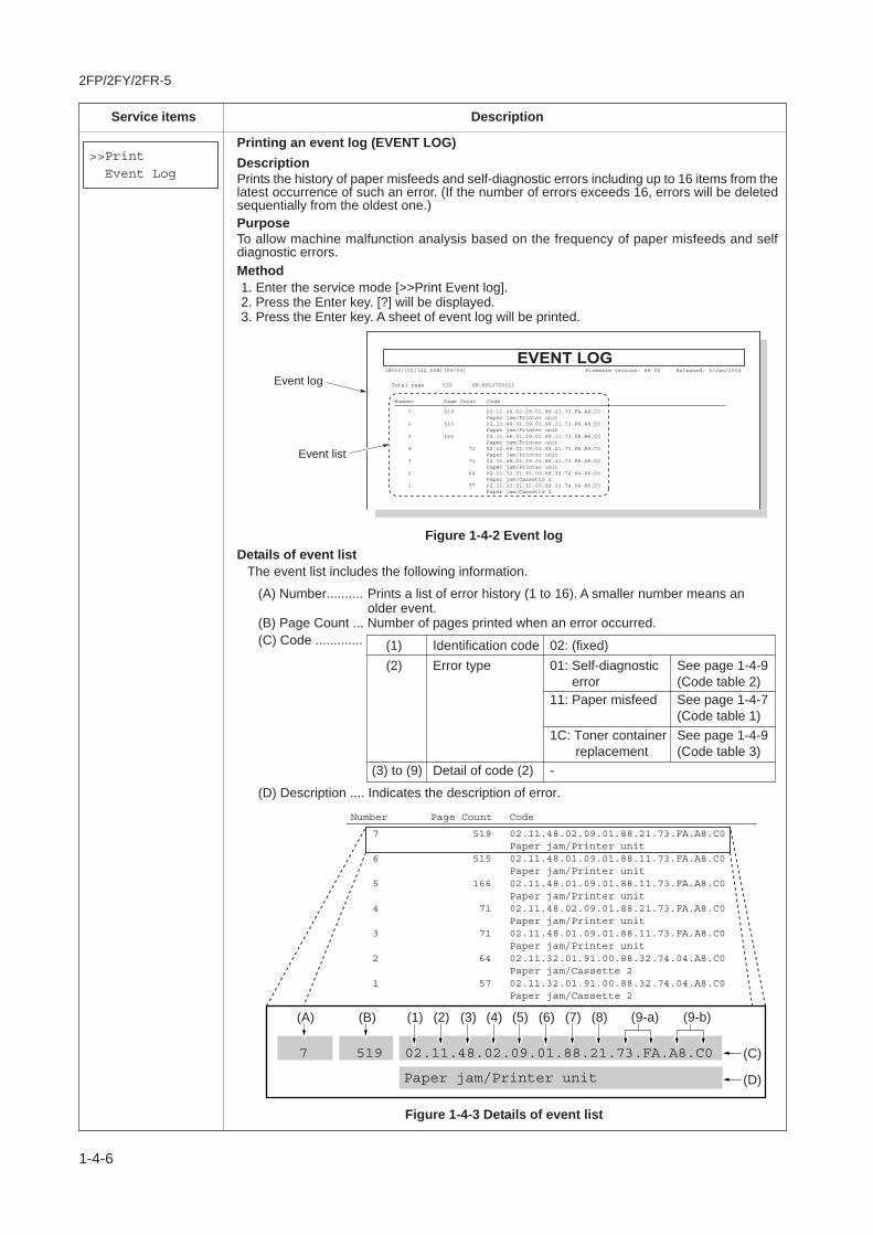
Printing an event log (EVENT LOG)DescriptionPrints the history of paper misfeeds and self-diagnostic errors including up to 16 items from thelatest occurrence of such an error. (If the number of errors exceeds 16, errors will be deletedsequentially from the oldest one.) PurposeTo allow machine malfunction analysis based on the frequency of paper misfeeds and selfdiagnostic errors.Method1. Enter the service mode [>>Print Event log].2. Press the Enter key. [?] will be displayed.3. Press the Enter key. A sheet of event log will be printed.
[A003][C1][22.00A][03/03] Firmware version: 88.00 Released: 9/Jan/2004
SN:SPL2700012
7 519 02.11.48.02.09.01.88.21.73.FA.A8.C0 Paper jam/Printer unit6 515 02.11.48.01.09.01.88.11.73.FA.A8.C0 Paper jam/Printer unit5 166 02.11.48.01.09.01.88.11.73.FA.A8.C0 Paper jam/Printer unit4 71 02.11.48.02.09.01.88.21.73.FA.A8.C0 Paper jam/Printer unit3 71 02.11.48.01.09.01.88.11.73.FA.A8.C0 Paper jam/Printer unit2 64 02.11.32.01.91.00.88.32.74.04.A8.C0 Paper jam/Cassette 21 57 02.11.32.01.91.00.88.32.74.04.A8.C0 Paper jam/Cassette 2
Number Page Count Code
Event list
Event log Total page 522
Figure 1-4-3 Details of event list
Event Log
Details of event listThe event list includes the following information.
(A) Number.......... Prints a list of error history (1 to 16). A smaller number means anolder event.
(B) Page Count ... Number of pages printed when an error occurred.(C) Code ............. (1) 02: (fixed)
-
(2)
1C: Toner container replacement
(3) to (9) Detail of code (2)
(D) Description .... Indicates the description of error.
7 519 02.11.48.02.09.01.88.21.73.FA.A8.C0Paper jam/Printer unit
6 515 02.11.48.01.09.01.88.11.73.FA.A8.C0Paper jam/Printer unit
5 166 02.11.48.01.09.01.88.11.73.FA.A8.C0Paper jam/Printer unit
4 71 02.11.48.02.09.01.88.21.73.FA.A8.C0Paper jam/Printer unit
3 71 02.11.48.01.09.01.88.11.73.FA.A8.C0Paper jam/Printer unit
2 64 02.11.32.01.91.00.88.32.74.04.A8.C0Paper jam/Cassette 2
1 57 02.11.32.01.91.00.88.32.74.04.A8.C0Paper jam/Cassette 2
Number Page Count Code
(D)
(C)
(A) (B) (1) (2) (3) (4) (5) (6) (7) (8) (9-a) (9-b)
7 519 02.11.48.02.09.01.88.21.73.FA.A8.C0
Paper jam/Printer unit
Figure 1-4-2 Event log
Error typeIdentification code
01: Self-diagnostic error
See page 1-4-9(Code table 2)See page 1-4-7(Code table 1)See page 1-4-9(Code table 3)
11: Paper misfeed

2FP/2FY/2FR-6
1-4-7
Service items Description
02: (fixed)
11: Paper misfeed
31: Cassette 1 (in the printer)32: Cassette 233: Cassette 334: Cassette 441: Envelope feeder42: MP tray46: Sorter48: Inside the printer49: Duplexer4A: Bulk paper feeder4B: (Reserved)
01: Registration sensor [48]Paper feed sensor [32]Paper feed sensor [33]Paper feed sensor [34]Vertical path sensor [49]Sorter [46]
02: Eject sensor [48]Switchback sensor [49]
03: Duplex refeed sensor [49]99: Not determined
Values within [ ] indicate paper misfeed locations.(hexadecimal)
01: Paper did not pass within a specified time.02: Paper did not arrive within a specified time.09: Paper remains longer than a specified time. (other than 01 and 02)11: Paper misfeed occurred when paper is being transported.91: Paper remains when power is turned on.99: Others (Paper stopped due to external cause such as opening of a cover during
printing.)
00: MP tray 04: Cassette 4 09: Duplexer01: Cassette 1 (in the printer) 05: (Reserved) 99: Envelope feeder02: Cassette 2 06: (Reserved)03: Cassette 3 08: Bulk paper feeder
Identificationcode
Error type(hexadecimal)
Paper misfeedlocations(hexadecimal)
Paper misfeedsensor loca-tion(hexadecimal)
Cause of pa-per misfeed(hexadecimal)
Paper source(hexadecimal)
(1)
(2)
(3)
(4)
(5)
(6)
Paper feeder 1
Paper feeder 2
Paper feeder 3
(Cassette 1)
(Cassette 2)
(Cassette 3)
(Cassette 4)
Duplexer
Sorter
Printer
42
46
48
49
31
32
33
34
(MP tray)(Inside the printer)
0102
02 03
01
01
01
01
01
41
4A
Envelopefeeder
Bulkpaperfeeder
Code digit anddescription
Details of code
Table 1-4-2 Code table 1

2FP/2FY/2FR-6
1-4-8
Service items Description
Paper size(hexadecimal)
Main cause ofpaper misfeed(hexadecimal)
(7)
(8)
01: Monarch
0D: A5
23: 216 x 316 (mm)
02: Business
0E: A6
24: A3 wide
03: International DL
0F: B6
25: Ledger wide
04: International C5
10: Commercial #9
27: 8K
05: Executive
11: Commercial #6
28: 16K
06: Letter
12: ISO B5
32: Statement
07: Legal
13: Custom size
33: Folio
08: A4
1E: C4
34: Western type 2
09: B5
1F: Postcard
35: Western type 4
0A: A3
20: Reply-paid postcard
86: Letter-R
0B: B4
21: Oficio II
88: A4R
0C: Ledger
22: 216 x 310 (mm)
89: B5R
10: Paper does not arrive at the registration sensor.11: Paper does not pass the registration sensor.12: Paper remains at the registration sensor when power is turned on.20: Paper does not arrive at the eject sensor.21: Paper does not pass the eject sensor.22: Paper remains at the eject sensor when power is turned on.30: Paper does not arrive at the paper feeder 1 feed sensor.31: Paper does not pass the paper feeder 1 feed sensor.32: Paper remains at the paper feeder 1 feed sensor when power is turned on.40: Paper does not arrive at the paper feeder 2 feed sensor.41: Paper does not pass the paper feeder 2 feed sensor.42: Paper remains at the paper feeder 2 feed sensor when power is turned on.50: Paper does not arrive at the paper feeder 3 feed sensor.51: Paper does not pass the paper feeder 3 feed sensor.52: Paper remains at the paper feeder 3 feed sensor when power is turned on.60: (Reserved)61: (Reserved)62: (Reserved)A1: Paper does not arrive at the vertical path sensor. (duplexer)A2: Paper does not arrive at the switchback sensor. (duplexer)A3: Paper does not pass the duplex refeed sensor. (duplexer)A4: Paper does not arrive at the duplexer refeed eject sensor.A5: Paper does not pass the duplexer refeed rear edge sensor.A6: Paper does not pass the duplexer refeed eject sensor.A7: Duplexer overflow (Third sheet is commanded when second sheet remains.)A8: Duplexer drive signal output from the printer while paper is transported turns off.A9: Paper remains in the duplexer when power is turned on.AA: The rear cover of the duplexer is opened while paper is transported.B1: Paper does not arrive at the tray paper sensor. (sorter)B2: Paper does not pass the tray paper sensor. (sorter)B3: Paper remains at the tray paper when power is turned on. (sorter)C1: (Reserved)E0: Paper misfeed occurs due to forced stop when an error occurs during printing. (such as opening of a cover)F0 to FF: Paper misfeed by another cause.
Code digit anddescription
Details of code
Table 1-4-2 Code table 1
Misfed paperwidth(hexadecimal)
Misfed paperlength(hexadecimal)
(9-a)
(9-b)
0000 to FFFF [in 0.1 mm]Example: 73FA (hexadecimal) = 29690 (decimal) = 296.9 mm
0000 to FFFF [in 0.1 mm]Example: A8C0 (hexadecimal) = 43200 (decimal) = 432.0 mm
2FP/2FY/2FR-5
1-4-9
Service items Description
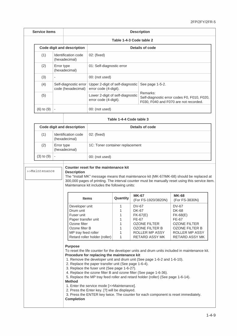
Identification code(hexadecimal)
Self-diagnostic errorcode (hexadecimal)
(1)
(4)
(6) to (9)
02: (fixed)
Error type(hexadecimal)
(2) 01: Self-diagnostic error
-
-
-
(3) 00: (not used)
00: (not used)
Upper 2-digit of self-diagnosticerror code (4-digit).
(5) Lower 2-digit of self-diagnosticerror code (4-digit).
Table 1-4-3 Code table 2
Table 1-4-4 Code table 3
Code digit and description Details of code
Code digit and description Details of code
Counter reset for the maintenance kitDescriptionThe "Install MK" message means that maintenance kit (MK-67/MK-68) should be replaced at 300,000 pages of printing. The interval counter must be manually reset using this service item.Maintenance kit includes the following units:
PurposeTo reset the life counter for the developer units and drum units included in maintenance kit.Procedure for replacing the maintenance kit 1. Remove the developer unit and drum unit (See page 1-6-2 and 1-6-10). 2. Replace the paper transfer unit (See page 1-6-4). 3. Replace the fuser unit (See page 1-6-27). 4. Replace the ozone filter B and ozone filter (See page 1-6-36). 5. Replace the MP tray feed roller and retard holder (roller) (See page 1-6-14).Method 1. Enter the service mode [>>Maintenance]. 2. Press the Enter key. [?] will be displayed. 3. Press the ENTER key twice. The counter for each component is reset immediately.Completion
>>Maintenance
Developer unitDrum unitFuser unitPaper transfer unitOzone filterOzone filter BMP tray feed rollerRetard roller holder (roller)
DV-67DK-67FK-67(E)FE-67OZONE FILTEROZONE FILTER BROLLER MP ASSYRETARD ASSY MK
11111111
DV-67DK-68FK-68(E)FE-67OZONE FILTEROZONE FILTER BROLLER MP ASSYRETARD ASSY MK
Items QuantityMK-67(For FS-1920/3820N)
MK-68(For FS-3830N)
Identification code(hexadecimal)
(1) 02: (fixed)
Error type(hexadecimal)
(2) 1C: Toner container replacement
(3) to (9) 00: (not used)-
See page 1-5-2.
Remarks:Self-diagnostic error codes F0, F010, F020, F030, F040 and F070 are not recorded.

2FP/2FY/2FR
1-4-10
Service items Description
>>Developer
Paper size switch
Figure 1-4-4
Initializing the developer unit (toner install mode)DescriptionThe new developer unit is shipped from the factory with no toner contained. The developer canbe automatically replete with toner when a toner container is installed onto it and the printer isturned on. However, because the toner reservoir in the developer has a large capacity, itrequires a lengthy period of time until a substantial amount of toner has been fed to get theprinter ready. (A new developer needs approximately 100 g for triggering the sensor inside.)PurposeTo execute when the developer unit has been replaced.Method1. Enter the service mode [>>Developer].2. Press the Enter key. [?] will be displayed.3. Press the Enter key.4. Turn off and on the printer. [Self test] [Please wait (Adding toner)] will displayed. The printer continually engages in
this mode for a period of approximately 8 minute, after which the printer reverts to the[Ready] state.
[Ready] will displayed. Developer initialization is finished.5. Make a test print by printing a status page.
NoteIf the printer is switched off in the middle of developer initialization, even after the printer isswitch on again, the printer will automatically resumes developer initialization. To cancel thetoner install mode in this case, first turn power off, press and hold all three paper size switches, and turn power on. Let go off of the switches when the unit message changes to [Ready].

2FP/2FY/2FR
1-4-11
Service items Description
Automatic drum surface refreshing
DescriptionThe drum surface refreshing operation is normally performed when the power is turned on tothe printer or during warm-up when the printer is recovering from the Sleep mode, but eventhen only at those times that the temperature/humidity sensor detects the drum surface to be ina state of dew condensation. By using this mode, it is possible to force the drum surfacerefreshing operation to be performed automatically at a predetermined period of time,regardless of the status detected by the temperature/humidity sensor.
PurposeTo prevent bleeding of the output image when the printer's operating environment is one ofhigh humidity.
Method1. Enter the service mode [>>DRUM-CTRL].2. Press the Enter key. [?] will be displayed.3. Press the Enter key.4. Press the or key and select the desire mode (from 00 to 02)
00 Mode turned OFF (default setting)
01 Refreshing operation time (short)
02 Refreshing operation time (long)
5. Press the Enter key. The new value is set.
Drum surface refreshing (drum cleaning mode)
DescriptionThis mode forces the printer to rotate the drum against the cleaning roller inside the drum unitfor a predetermined period of time.The printer automatically activates the drum cleaning mode based on the environmentalconditions that the temperature/humidity sensor detects. The time required to complete thedrum cleaning mode varies depending on the current setting for the sleep timer and will bedeactivated during developer initialization.
PurposeTo clean the drum surface when an image problem occurs.
Method1. Enter the service mode [>>Drum].2. Press the Enter key. [?] will be displayed.3. Press the Enter key. Drum surface refreshing will start. The drum is cleaned by the cleaning blade in the drum unit. If paper is present on the MP
tray, the drum is also cleaned by the paper that is fed automatically and stops at thetransfer roller.
>>Drum
>>DRUM-CTRL
00

2FP/2FY/2FR
1-4-12
1-4-2 Maintenance
(1) Cleaning the paper transfer unit
To avoid print quality problems due to paper dust and debris, clean the paper transfer unit in the following manner.
Pull the paper transfer unit release lever up and draw the paper transfer unit all the way out until it stops.Wipe the paper dust on the upper registration roller and the paper ramp using the wiper cloth included in the toner kit.
CAUTIONS Do not touch the transfer roller (black sponge roller) when wiping the paper ramp.
Area (A) below is factory-applied with lubricating oil. When cleaning the paper transfer unit, do not use alcohol to clean thisarea. If the oil is completely removed, an incorrect action of the MP tray paper sensor (actuator) will result.
Upper registrationroller
Paper transfer unit release lever
Transfer roller
Paper ramp
Wipercloth
(A)Paper
transfer
unit
MP tray paper
sensor (actuator)
Figure 1-4-5
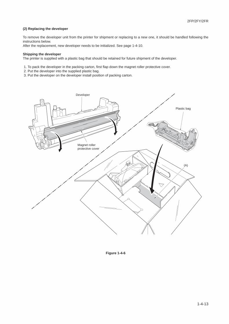
2FP/2FY/2FR
1-4-13
(2) Replacing the developer
To remove the developer unit from the printer for shipment or replacing to a new one, it should be handled following theinstructions below.After the replacement, new developer needs to be initialized. See page 1-4-10.
Shipping the developerThe printer is supplied with a plastic bag that should be retained for future shipment of the developer.
1. To pack the developer in the packing carton, first flap down the magnet roller protective cover. 2. Put the developer into the supplied plastic bag. 3. Put the developer on the developer install position of packing carton.
Magnet roller
protective cover
Developer
(A)
Plastic bag
Figure 1-4-6

2FP/2FY/2FR
1-4-14
This page is intentionally left blank.
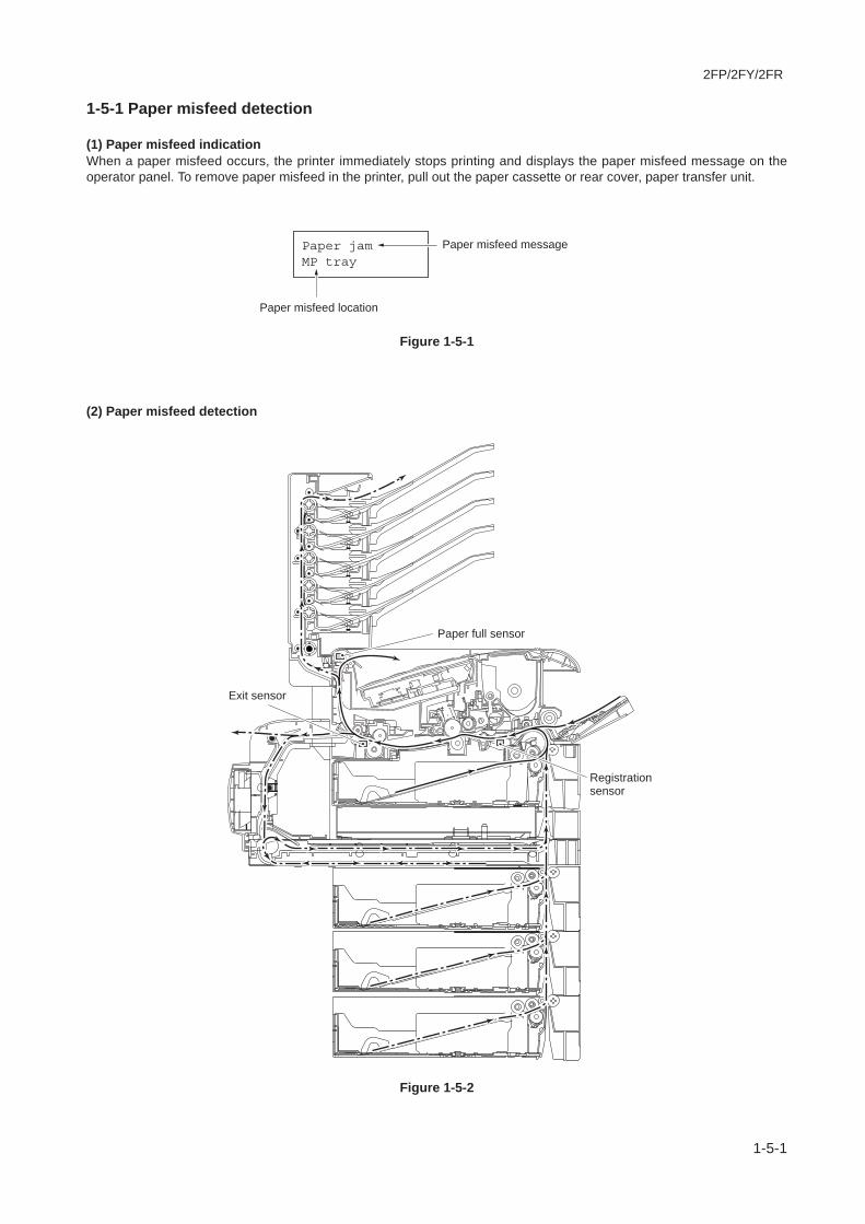
2FP/2FY/2FR
1-5-1
1-5-1 Paper misfeed detection
(1) Paper misfeed indicationWhen a paper misfeed occurs, the printer immediately stops printing and displays the paper misfeed message on theoperator panel. To remove paper misfeed in the printer, pull out the paper cassette or rear cover, paper transfer unit.
Figure 1-5-1
(2) Paper misfeed detection
Figure 1-5-2
Paper jamMP tray
Paper misfeed location
Paper misfeed message
Paper full sensor
Exit sensor
Registrationsensor
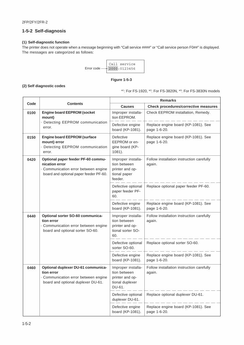
2FP/2FY/2FR-2
1-5-2
Engine board EEPROM (socketmount)
· Detecting EEPROM communicationerror.
Engine board EEPROM (surfacemount) error
· Detecting EEPROM communicationerror.
Optional paper feeder PF-60 commu-nication error
· Communication error between engineboard and optional paper feeder PF-60.
Optional sorter SO-60 communica-tion error
· Communication error between engineboard and optional sorter SO-60.
Optional duplexer DU-61 communica-tion error
· Communication error between engineboard and optional duplexer DU-61.
Improper installa-tion EEPROM.
Defective engineboard (KP-1081).
DefectiveEEPROM or en-gine board (KP-1081).
Improper installa-tion betweenprinter and op-tional paperfeeder.
Defective optionalpaper feeder PF-60.
Defective engineboard (KP-1081).
Improper installa-tion betweenprinter and op-tional sorter SO-60.
Defective optionalsorter SO-60.
Defective engineboard (KP-1081).
Improper installa-tion betweenprinter and op-tional duplexerDU-61.
Defective optionalduplexer DU-61.
Defective engineboard (KP-1081).
Check EEPROM installation, Remedy.
Replace engine board (KP-1081). Seepage 1-6-20.
Replace engine board (KP-1081). Seepage 1-6-20.
Follow installation instruction carefullyagain.
Replace optional paper feeder PF-60.
Replace engine board (KP-1081). Seepage 1-6-20.
Follow installation instruction carefullyagain.
Replace optional sorter SO-60.
Replace engine board (KP-1081). Seepage 1-6-20.
Follow installation instruction carefullyagain.
Replace optional duplexer DU-61.
Replace engine board (KP-1081). Seepage 1-6-20.
0100
0150
0420
0440
0460
(2) Self diagnostic codes*1: For FS-1920, *2: For FS-3820N, *3: For FS-3830N models
Code ContentsRemarks
Causes Check procedures/corrective measures
1-5-2 Self-diagnosis
(1) Self-diagnostic functionThe printer does not operate when a message beginning with “Call service ####” or “Call service person F0##” is displayed.The messages are categorized as follows:
Call service2000:0123456Error code
Figure 1-5-3

2FP/2FY/2FR-2
1-5-3
Code ContentsRemarks
Causes Check procedures/corrective measures
Non-supported duplexer is installed·Non-supported duplexer DU-60 is
installed
Paper feeder PF-60 [top] with wrongfirmware version is installed
·The code that identifies the firmwareversion was out of range.
Paper feeder PF-60 [middle] withwrong firmware version is installed
·The code that identifies the firmwareversion was out of range.
Bulk paper feeder PF-8E with wrongfirmware version is installed
·The code that identifies the firmwareversion was out of range.
Paper feeder PF-60 [bottom] withwrong firmware version is installed
·The code that identifies the firmwareversion was out of range.
Optional duplexer DU-61 side regis-tration error
· Side registration home position error ofoptional duplexer DU-61.
DU-60 is in-stalled.
Wrong firmwareversion is usedon the mainboard in paperfeeder PF-60.
Wrong firmwareversion is usedon the mainboard in paperfeeder PF-60 orbulk paper feederPF-8E.
Wrong firmwareversion is usedon the mainboard in paperfeeder PF-60.
Defective gatearray U7 on theengine board(KP-1081).
Improper installa-tion betweenprinter and op-tional duplexer, oreach optionalunit.
Defective har-ness (S03022)between engineboard and op-tional unit inter-face connector.
Improper connec-tor insertion.
Defective optionalduplexer DU-61.
Replace duplexer DU-60 for DU-61.
Change the main board with the one hav-ing the correct firmware in paper feederPF-60.
Change the main board with the one hav-ing the correct firmware in paper feederPF-60 or bulk paper feeder PF-8E.
Change the main board with the one hav-ing the correct firmware in paper feederPF-60.
Replace engine board (KP-1081). Seepage 1-6-20.
Follow installation instruction carefullyagain.
Replace harness (S03022).
Remedy.
Refer to the optional duplexer DU-61’sservice manual.
0550
0560
0570
0580
1200

2FP/2FY/2FR
1-5-4
Code ContentsRemarks
Causes Check procedures/corrective measures
Main motor error• The main motor is overloaded.
Overcurrent in themain motor cir-cuitry due to anexcessive torque.
Connector inser-tion error.
Defective gatearray U7 on theengine board (KP-1081).
Defective harnessbetween engineboard and enginerelay board (KP-1071).
Defective harnessbetween enginerelay board (KP-1071) and mainmotor.
Follow the flow chart below.2000
Print status page.
Yes
Yes
No
No
Replace engine board (KP-1081). See page 1-6-20.
Does pin #18 (MMOTRDY*)
of YC7 on engine board goes low, after pin #16
(MMOTON*) of YC7 goes
low?
Yes
Yes
No
No
Replace harness (S03012) between engine board (KP-1081) and engine relay board (KP-1071).
Replace engine relay board (KP-1071). See page 1-6-13.
OK?
START
Remove and check harness (S03012) between engine board (KP-1081) and engine relay board (KP-1071),or harness (S02401*1*3/S03026*2)between engine relay board (KP-1071) and main motor.
+24 V DC at #1 pin of YC802 on engine board
(KP-1081) ?
Does pin #16 (MMOTON*)
of YC7 on engine board (KP-1081) goes high,
then low?
Print status page.
Turn power switch off.
Turn power switch on.
Replace Main motor.See page 1-6-25.
NOTE:If the problem is not solved by this flow chart replace the following items:
Harness (S03012) between engine relay board (KP-1071) and engine board (KP-1081)
Drive unit (See page 1-6-25.)
Engine board (KP-1081) and main motor (replace at the same time)
*1: FS-1920 model*2: FS-3820N model*3: FS-3830N model

2FP/2FY/2FR
1-5-5
Code ContentsRemarks
Causes Check procedures/corrective measures
Optional bulk paper feeder PF-8Emotor error
• Motor error in the optional bulk paperfeeder PF-8E.
Optional paper feeder PF-60 (Top)paper feed motor error
• Paper feed motor error in the top optionalpaper feeder.
Optional paper feeder PF-60 (Middle)paper feed motor error
• Paper feed motor error in the middleoptional paper feeder.
Optional paper feeder PF-60 (bot-tom) paper feed motor error
• Paper feed motor error in the bottomoptional paper feeder.
Defective harness(S03022) betweenengine board andoptional unit inter-face connector.
Defective optionalbulk paper feeder.
Defective gatearray U7 on theengine board (KP-1081).
Defective harness(S03022) betweenengine board andoptional unit inter-face connector.
Defective paperfeeder PF-60.
Defective gatearray U7 on theengine board (KP-1081).
Defective harness(S03022) betweenengine board andoptional unit inter-face connector.
Defective optionalpaper feeder PF-60.
Defective gatearray U7 on theengine board (KP-1081).
Defective harness(S03022) betweenengine board andoptional unit inter-face connector.
Defective paperfeeder PF-60.
Replace engine board (KP-1081). Seepage 1-6-20.
Replace harness (S03022).
Replace engine board (KP-1081). Seepage 1-6-20.
Replace harness (S03022).
Refer to optional paper feeder PF-60’s ser-vice manual.
Replace engine board (KP-1081). Seepage 1-6-20.
Replace harness (S03022).
Refer to optional paper feeder PF-60’s ser-vice manual.
Replace engine board (KP-1081). Seepage 1-6-20.
Replace harness (S03022).
Refer to optional paper feeder PF-60’s ser-vice manual.
2600
2610
2620
2630

2FP/2FY/2FR
1-5-6
Code ContentsRemarks
Causes Check procedures/corrective measures
Laser scanner unit (Polygon motor)error
• POLRDY* does not go low within 20seconds after POLON* goes low (Whenstarting) or within 16 seconds afterREGPAP signal goes high (duringprinting).
Defective gatearray U7 on theengine board. Defective poly-gon motor.
Improper connec-tor insertion.
Defective har-ness between la-ser scanner unitand engine board.
Follow the flow chart below.4000
Yes
Yes
Yes
No
NoNo
NoDoes
pin #31 (POLON*) of YC7 on engine board (KP-1081) goes high
and then low?
Doespin #29 (POLCLK) of YC7 on engine board
(KP-1081) output square-wave*1
signal?
Call service4000:01234546
*1: 2.7165 KHz
Print status page.
Print status page.
Print status page.
Remove and check harness between engine board (KP-1081) and laser scanner unit.
Turn power switch off.
Turn power switch on.
+24 V DC at #33 pin of YC7 on engine board
(KP-1081) ?
Yes
Yes
No
Replace harness between engine board (KP-1081) and laser scanner unit.
OK?
START
Replace engine board (KP-1081). See page 1-6-20.
Replace engine board (KP-1081). See page 1-6-20.
Replace laser scanner unit. See page 1-6-35.
Does pin #30 (POLRDY*)
of YC7 on engine board goes low, after pin #31
(POLON*) of YC7 goes low?
NOTE:When If not solved this flow chart, try to replace below items.
Harness (S03012) scanner unit and engine board (KP-1081)
Engine board (KP-1081) and scanner unit (replace at the same time)
NOTE:Pins of YC7 connector are crowded and tiny. When if measuring signal, contact measurement probe with pins of YC7 connector accurately.

2FP/2FY/2FR
1-5-7
Code ContentsRemarks
Causes Check procedures/corrective measures
Laser scanner unit (Pin photo diodesensor) error
• Laser beam detection failed. The pinphoto diode sensor [board] (KP-1075)does not deliver a horizontal synchronoussignal (PD*).
No laser beamdue to the laserdiode defect(PD*).
Soiled or defec-tive pin photo di-ode sensor.
Defective gatearray U7 of en-gine board.
Improper connec-tor insertion.
Defective har-ness between en-gine board andlaser scanner unit.
Follow the flow chart below.4200
Yes
No
Yes
No
No
Print status page.
Turn power switch off.
Turn power switch on.
Print status page.Remove and check harness between engine board (KP-1081) and laser scanner unit.
+24 V DC at #1 pin of YC601
on APC board (KP-1062) ?
Yes
Yes
No
Replace harness between engine board (KP-1081) and laser scanner unit.
OK?
START
Replace engine board (KP-1081). See page 1-6-20.
Replace engine board (KP-1081). See page 1-6-20.
Replace laser scanner unit. See page 1-6-35.
Doespin #4 (LASER*) of
YC601 on APC board (KP-1062) goes high
and then low?
Pin #8 (_PDIN*) of YC601 on APC board (KP-1062) output pulse
signal*1 ?
*1: Pin photo diode sensor[board KP-1075] detecting horizontal synchronization signal
Frequency: 2.7 kHz, Low level width: 1.4 ms
NOTE:If the problem is not solved by this flow chart replace the following items:
Harness (S03012 ) laser scanner unit and engine board (KP-1081)
Engine board (KP-1081) and laser scanner unit (replace at the same time)

2FP/2FY/2FR
1-5-8
Code ContentsRemarks
Causes Check procedures/corrective measures
Eraser lamp error• The ERADEAD* signal (delivered from
the eraser lamp blown-out detectioncircuit on the engine board) goes lowcontinuously more than 1 second, whileeraser lamp is on.
Blown-out eraserlamp [board KP-1067].
Defective CPU U1on the engineboard.
Improper connec-tor insertion to theeraser lamp[board KP-1067].
Follow the flow chart below.5300
Remove and check harness (S02407) between engine board (KP-1081) and sensor board (KP-1077).
Yes
Yes
Yes
Yes
No
No
No
No
Replace sensor board (KP-1077) and linked harness (S02407).
Approximately14 to 15.5 V DC?
Approximately24 V DC?
Remove and check harness (S02412) between drum board (KP-1064) and eraser lamp [board KP-1067].
Check deformation pins of connector YC702 on sensor board.
Yes
Yes
No
No
Replace harness (S02412) between drum board (KP-1064) and eraser lamp [board KP-1067].
OK?
OK?
START
Turn power switch on and print status page.
Turn power switch off.
Measure voltage #1 pin (ERASEDR*) pins of connector YC701 on sensor board (KP-1077).
Remedy pins or replace sensor board (KP-1077). See page 1-6-24.
Replace engine board (KP-1081. See page 1-6-20.
Replace sensor board (KP-1077). See page 1-6-24.
Replace drum unit.See page 5-12.
Deformed ?
Engine board (KP-1081)Sensor board (KP-1077)Drum unit
Approximately0 V DC?
Replace drum unit.See page 1-6-10.
NOTE:If the problem is not solved by this flow chart replace the following items:

2FP/2FY/2FR
1-5-9
Code ContentsRemarks
Causes Check procedures/corrective measures
Fuser unit error• HTEMP* remains high for longer than 4
seconds since the heater lamp is on. Theheater lamp continues to be turn on forlonger than 60 seconds.
Blown-out ther-mistor.
Blown-out heaterlamp.
Defective CPU U1or comparator U9on the engineboard.
Improper connec-tor insertion.
Defective powersupply unit.
Defective harnessbetween fuser unitand power supplyunit.
Follow the flow chart below.6000
Yes
Yes
No
No
No
Remove and check harness (S02678) between fuser board (KP-1069) and power supply unit, orthermistor connector(YC834) on the fuser board (KP-1069).
0 V DC at pin #6 (THERM)
of YC831 on fuser board (KP-1069) ?
Yes
Yes
No
Replace harness (S02678) between fuser board (KP-1069) and power supply unit.
OK?
"6000"shown?
End.
Turn power switch on.
Turn power switch off, and remove power cable.
Turn power switch off.
Turn power switch on.
Detach connector CN2 (A) on power supply board.
Measure resistance between pins 1 and 3 of the detached connector.
Replace power supply unit. See page 1-6-20.
Replace engine board (KP-1081). See page 1-6-20.
Replace fuser unit. See page 1-6-27.
Open (infinite)?
CAUTION:Fuser unit is fed directly by AC power from primary circuit on power supply board. Be careful with electric shock.Fuser unit is extremely hot immediately after the printer was running. Allow substantial period of time until it cools down.
See figure right.
(A)
Heater lamp1
3
Replace fuser unit. See page 1-6-27.
START

2FP/2FY/2FR
1-5-10
Code ContentsRemarks
Causes Check procedures/corrective measures
Abnormal high temperature error• HTEMP* remains high for longer than 4
seconds since the heater lamp is on. Theheater lamp continues to be turn on forlonger than 60 seconds.
Defective CPU U1or comparator U9on the engineboard.
Defective engineboard (KP-1081).
Defective ther-mistor.
Defective photocoupler on thepower supply unitfor the heaterlamp.
Follow the flow chart below.6020
No
Remove and check harness (S02678) between fuser board (KP-1069) and power supply unit.
Yes
Yes
No
Replace harness (S02678) between fuser board (KP-1069) and power supply unit.
OK?
STRAT
Replace engine board (KP-1081). See page 1-6-20.
Replace fuser unit. See page 1-6-27.
CAUTION:Fuser unit is fed directly by AC power from primary circuit on power supply board. Be careful with electric shock.
Measure voltage at pin #6 (THERM) of YC831 on fuser board (KP-1069).
Turn power switch off.
Turn power switch on.
More than 3 V DC over 3
seconds?
NOTE:If the problem is not solved by this flow chart replace, the following items:
Engine board (KP-1081)Power supply unitFuser unit
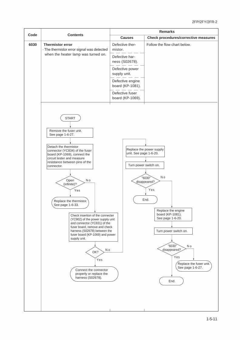
2FP/2FY/2FR-2
1-5-11
Code ContentsRemarks
Causes Check procedures/corrective measures
Thermistor error· The thermistor error signal was detected
when the heater lamp was turned on.
Defective ther-mistor.
Defective har-ness (S02678).
Defective powersupply unit.
Defective engineboard (KP-1081).
Defective fuserboard (KP-1069).
Follow the flow chart below.6030
N o
Replace the fuser unit.
See page 1-6-27.
N o
N o
Yes
Yes
OK?
N o
Yes
End.
Yes
"6030"
disappeared?
"6030"
disappeared?
End.
Turn power switch on.
Turn power switch on.
Replace the thermistor.
See page 1-6-33.
Replace the power supply
unit. See page 1-6-20.
Detach the thermistor
connector (YC834) of the fuser
board (KP-1069), connect the
circuit tester and measure
resistance between pins of the
connector.
Replace the engine
board (KP-1081).
See page 1-6-20.
Open
(infinite)?
Remove the fuser unit.
See page 1-6-27.
START
Connect the connector
properly or replace the
harness (S02678).
Check insertion of the connecter
(YC902) of the power supply unit
and connector (YC831) of the
fuser board, remove and check
harness (S02678) between the
fuser board (KP-1069) and power
supply unit.

2FP/2FY/2FR
1-5-12
Code ContentsRemarks
Causes Check procedures/corrective measures
Zero cross signal error• The ZCROSS signal does not reach
the engine board within 3 secondsafter power on.
Toner motor error• Toner motor is overloaded. TNMOC
is detected by sampling every other100 ms in 2 seconds since the mainand toner motors are activated follow-ing the Replace toner Clean printermessage after the “Toner low” is de-tected.
Defective powersupply unit.
Defective CPU U1on the engineboard.
Overcurrent in thetoner motor cir-cuitry due to anexcessive torque,caused by hard-ened toner.
Defective gatearray U7 on theengine board.
Improper connec-tor insertion.
Defective harnessbetween devel-oper and highvoltage unit.
Defective harnessbetween high volt-age unit and en-gine board.
Replace power supply unit. See page 1-6-20.
Replace engine board. See page 1-6-20.
Follow the flow chart below.
6400
7001
Replace with a new toner kit.
Yes
No
"7001"shown?
Replace engine board (KP-1081) and developer. See page 1-6-20 and 1-6-2.
High voltage unit
End.
START
Harness (S02416) [Between developer and high voltage unit]Harness (S02408) [Between engine board and high voltage unit]
NOTE:If the problem is not solved by this flow chart, replace the following items:

2FP/2FY/2FR-2
1-5-13
Code ContentsRemarks
Causes Check procedures/corrective measuresToner refreshing mode error
• Toner refreshing mode error.
The developer unit is not installed ornot installed properly
• Failed to detect the voltage to identifythe developer.
The drum unit is not installed or notinstalled properly
• EEPROM communication error or thedrum ID was not identified.
Non-supported device is installed asan optional exit
• Serial communication detected that anon-supported bulk paper stackerHS-8E has been installed.
Main board or LCD controller boarderror
• Communication is failed between theLCD controller board (KP-1079) and themain board.
System DIMM [board] error• Checksum failed with system DIMM
[board KP-1059*1/893*2*3] on the mainboard.
Defective highvoltage unit.
Defective tonerrefreshing.
The developer unitis not installed.
The developerconnector is notproperly insertedin the printer.
Defective devel-oper unit.
Defective engineboard (KP-1081).
The drum unit isnot installed.
The drum unitconnector is notproperly insertedin the printer.
Defective drumunit.
Defective engineboard (KP-1081).
A non-supportedbulk paper stackerHS-8E is in-stalled.
Defective systemDIMM [board KP-1059*1/893*2*3].
Defective mainboard (KP-1053*1/1033*2*3).
LCD controllerboard (KP-1079).
Defective systemDIMM [board KP-1059*1/893*2*3].
Improper systemDIMM [board KP-1059*1/893*2*3]insertion to sys-tem DIMM slot onthe main board(KP-1053*1/1033*2*3).
Replace high voltage unit. See page 1-6-23.
See page 1-4-10.
Install the developer unit. See page 1-6-2.
Follow installation instructions for devel-oper carefully again.
Replace the developer unit. See page 1-6-2.
Replace the engine board (KP-1081). Seepage 1-6-20.
Install the drum unit. See page 1-6-10.
Follow the installation instructions for thedrum unit carefully again.
Replace the drum unit. See page 1-6-10.
Replace the engine board (KP-1081). Seepage 1-6-20.
Remove the bulk paper stacker HS-8E.
Replace system DIMM [board KP-1059*1/893*2*3] or main board (KP-1053*1/1033*2*3).
Replace system DIMM [board KP-1059*1/893*2] or main board (KP-1053*1/1033*2*3).
Replace LCD controller board (KP-1079).
Replace system DIMM [board KP-1059*1/893*2*3] or main board (KP-1053*1/1033*2*3).
Reinsert the system DIMM [board KP-1059*1/893*2*3].
7350
7400
7410
8000
F0
F010

2FP/2FY/2FR
1-5-14
Code ContentsRemarks
Causes Check procedures/corrective measures
Main or expanded memory error• Checksum failed with main memory
(RAM) on the main board orexpanded memory (DIMM).
General failure• Miscellaneous failure with the main
board, other than F0, F010 and F020,above.
Communication error• Communication between the engine
board and the main board is failed.
Flash ROM error• CPU U1 of engine board could not
write data failed to flash ROM U2.Write sequence to flash ROM is notsuccessful. Verify error. (Written datadoes not match the original data.)
Defective systemmain memory(RAM) on themain board (KP-1059*1/893*2*3).
Defective mainboard (KP-1053*1/1033*2*3).
Defective expand-ing memory(DIMM) on themain board (KP-1053*1/1033*2*3).
Defective mainboard (KP-1053*1/1033*2*3).
Defective gatearray (U02) on themain board.
Connector failurebetween the en-gine board (KP-1081) and mainboard (KP-1053*1/1033*2*3).
Overrun in theengine system,deactivating theprogram flashROM (U2) on theengine board (KP-1081).
Defective CPU U1or gate array U7or flash ROM U2on the engineboard (KP-1081).
Defective system main memory (RAM) onthe main board (KP-1053*1/1033*2*3).
Defective main board (KP-1053*1/1033*2*3).
Defective expanding memory (DIMM) onthe main board (KP-1053*1/1033*2*3).
Replace main board (KP-1053*1/1033*2*3).
Replace the main board (KP-1053*1/1033*2*3). See page 1-6-24.
Verify connector connections.
Replace the engine board (KP-1081). Seepage 1-6-20.
Replace engine board (KP-1081).
F020
F030
F040
F070

2FP/2FY/2FR
1-5-15
1-5-3 Image formation problems
(1) Completely blank print-out.
See page 1-5-16
(2) All-black printout.
See page 1-5-16
(3) Dropouts.
ABC123
See page 1-1-6-17
(4) Black dots.
ABC123
See page 1-1-6-17
(5) Black horizontalstreaks.
ABC123
See page 1-1-6-18
(6) Black vertical streaks.
ABC123
See page 1-5-18
(7) Unsharpness.
See page 1-5-19
(8) Gray background.
ABC123
See page 1-5-19
(9) Dirt on the top edgeor back of the paper.
ABC123
See page 1-5-20
(10)Undulated printing atthe left edge (scan-ning start position).
This verticalline shouldbe straight.
See page 1-5-20

2FP/2FY/2FR
1-5-16
(1) Completely blankprintout.
Causes1. Defective developer2. Defective transfer bias potential3. Defective laser scanner unit4. Defective main board
Causes Check procedures/corrective measures1. Defective developer
2. Defective transfer bias potential
3. Defective laser scanner unit
4. Defective main board
Check that the developer is inserted correctly. See page 1-6-2.Check that the toner on the magnet roller surface. See page 1-6-2.Check the transfer bias output on the high voltage unit. This requiresremoval of the left cover and the test equipment. Replace the highvoltage unit if high voltage potential is not available on the board.See page 1-6-23.The scanner components within the scanner may be disordered.Replace the laser scanner unit. See page 1-6-35.Defective laser scanner unit control circuit in the main board (KP-1053*1/1033*2*3). See page 1-6-22.Defective laser scanner unit control circuit in the main board (KP-1053*1/1033*2*3). See page 1-6-22.
(2) No image appears(entirely black).
Causes1. Defective main charger unit2. Defective drum bias3. Defective high voltage unit4. Defective main board
Causes Check procedures/corrective measures1. Defective main charger unit
2. Defective drum bias
3. Defective high voltage unit
4. Defective main board
Open the printer side cover and check that the drum unit is correctlyseated. Check for poor contact of the main charger terminal betweenthe main charger unit and the drum unit.Make sure the bias from the high voltage unit correctly arrives at thedrum unit.Check the high voltage output on the high voltage unit. Replace thehigh voltage unit if high voltage potential is not available on theboard.Defective laser scanner unit control circuit in the main board (KP-1053*1/1033*2*3). See page 1-6-22.
*1: For FS-1920, *2: For FS-3820N, *3: For FS-3830N models
*1: For FS-1920, *2: For FS-3820N, *3: For FS-3830N models

2FP/2FY/2FR
1-5-17
Causes Check procedures/corrective measures1. Defective developing roller (in the developer)
2. Defective drum unit
3. Defective fuser unit
4. Defective paper specifications
5. Defective transfer roller installation
6. Defective high voltage unit (transfer biaspotential)
If the defects occur at regular intervals of 39 mm, the problem maybe the damaged developing roller (in the developer). Replace thedeveloper. See page 1-6-2.If the defects occur at regular intervals of 94 mm, the problem maybe the damaged drum (in the drum unit). Replace the drum unit.See page 1-6-10.If the defects occur at regular intervals of 72 mm (heat roller) or 79mm (press roller), the problem may be the damaged fuser unit.Replace the press roller or heat roller. See page 1-6-32 or 1-6-34.Paper with rugged surface or dump tends to cause dropouts.Replace paper with the one that satisfies the paper specifications.The transfer roller must be supported by the bushes at the bothends. Clean the bush to remove oil and debris. Replace the transferroller if necessary. See page 1-6-15.Check the transfer bias output on the high voltage unit. This requiresremoval of the left cover and the test equipment. Replace the highvoltage unit if high voltage potential is not available on the board.See page 1-6-23.
(3) Dropouts. Causes1. Defective developing roller (in the developer)2. Defective drum unit3. Defective fuser unit4. Defective paper specifications5. Defective transfer roller installation6. Defective high voltage unit (transfer bias potential)
Causes Check procedures/corrective measures1. Defective drum unit If the defects occur at regular intervals of 94 mm, the problem may
be the damaged drum (in the drum unit). Replace drum unit. Seepage 1-6-10.If the defects occur at random intervals, the toner may be leakingfrom the developer and drum unit. Replace developer and drum unit.See page 1-6-2 and 1-6-10.
(4) Black dots. Causes1. Defective drum unit
ABC123
ABC123

2FP/2FY/2FR
1-5-18
Causes Check procedures/corrective measures1. Contaminated main charger wire
2. Defective drum surface
3. Defective magnet roller (in the developer)
Clean the main charger wire by pulling the green colored cleaningknob in and out several times.A streak of toner remaining on drum after printing means that thecleaning blade (in the drum unit ) is not working properly. Replacethe drum unit. See page 1-6-10.Replace the developer. See page 1-6-2.
(6) Black verticalstreaks.
Causes1. Contaminated main charger wire2. Defective drum surface3. Defective magnet roller (in the developer)
Causes Check procedures/corrective measures1. Defective drum unit's ground
2. Defective drum unit
The drum axle in the drum unit and its counter part, the groundingtab in the printer, must be in a good contact. If necessary, apply asmall amount of electro-conductive grease onto the tab.Replace the drum unit. See page 1-6-10.
(5) Black horizontalstreaks.
Causes1. Defective drum unit's ground2. Defective drum unit
ABC123
ABC123

2FP/2FY/2FR
1-5-19
Causes Check procedures/corrective measures1. Defective paper specifications
2. Defective transfer roller installation
3. Defective transfer bias potential
4. EcoPrint setting
Paper with rugged surface or dump tends to cause unsharp printing.Replace paper with the one that satisfies the paper specifications.The transfer roller must be supported by the bushes at the bothends. Clean the bush to remove oil and debris. Replace the transferroller if necessary. See page 1-6-15.Check the transfer bias output on the high voltage unit. This requiresremoval of the left cover and the test equipment. Replace the highvoltage unit if high voltage potential is not available on the board.See page 1-6-23.The EcoPrint mode can provides faint, unsharp printing because itacts to conserve toner for draft printing purpose. For normal printing,turn the EcoPrint mode off by using the operator panel. For detailsrefer to the printer's user's manual.
(7) Unsharpness. Causes1. Defective paper specifications2. Defective transfer roller installation3. Defective transfer bias potential4. EcoPrint setting
Causes Check procedures/corrective measures1. Print density setting
2. Defective drum surface potential
3. Grid
4. Developing roller (in the developer)
The print density may be set too high. Try adjusting the print densityusing the Remote operation panel utility. For details refer to theprinter's user's manual.The drum surface potential should be approximately 230±15 V. Thismay vary depending on production lots. Measurement is possibleonly by using the jig and tool specifically designed for this purpose.The drum unit will have to be replaced if it bears values far out of theallowable range.Clean the grid by grid cleaner. For details refer to the printer's user'smanual.If a developer which is known to work normally is available for check,replace the current developer in the printer with the normal one. Ifthe symptom disappears, replace the developer with a new one.See page 1-6-2.
(8) Gray background. Causes1. Print density setting2. Defective drum surface potential3. Grid4. Developing roller (in the developer)
ABC123

2FP/2FY/2FR-2
1-5-20
Causes Check procedures/corrective measures1. Defective laser scanner unit
2. Defective engine controller circuit in theengine board
Defective polygon motor in the laser scanner unit. Replace the laserscanner unit. See page 1-6-35.Replace the engine board (KP-1081). See page 1-6-20.
(10) Undulated printing atthe left edge (scan-ning start position).
Causes1. Defective laser scanner unit2. Defective engine controller circuit in the engine board
Causes Check procedures/corrective measures1. Toner contamination in various parts
2. Defective transfer roller
Dirty edges and back of the paper can be caused by toneraccumulated on such parts as the paper chute, paper transportationpaths, the bottom of the drum and developer, and the fuser unit inlet.Clean these areas and parts to remove toner.If the transfer roller is contaminated with toner, clean the transferroller using a vacuum cleaner or by continuously printing a low-density page until the symptom has faded away.
(9) Dirt on the top edgeor back of the paper.
Causes1. Toner contamination in various parts2. Defective transfer roller
ABC123
This verticalline shouldbe straight.

2FP/2FY/2FR-2
1-5-21
(1) Defective wastetoner box detecting.• Although new
waste toner box isinstalled, Checkwaste toner box isdisplayed. Al-though wastetoner bottle is notinstalled, Ready isdisplayed.
(2) Defective paperjam detecting.
• Paper jam fre-quently occurs.
• False paper jammessage display.
(3) Defective papergauge sensing.• False paper gauge
indication.
Defective waste toner fullsensor [board] (KP-1065)or waste toner sensor (re-ceiver).
Deformed pins of connec-tor (YC702) on the sensorboard (KP-1077).
Defective engine board(KP-1081).
Surface of the registrationsensor (PH701) is dirtywith paper particles.
Actuators of registrationsensor (PH701) or exitsensor does not operatesmoothly.
Defective sensor board(KP-1077), fuser board(KP-1069) or engine board(KP-1081).
A piece of paper torn froma sheet is caught aroundactuator of registrationsensor or exit sensor.
Surface of the papergauge sensor 1 (PH702)and 2 (PH703) on the sen-sor board (KP-754) aredirty with paper particles.
A piece of paper torn froma sheet is caught aroundpaper gauge sensor 1(PH702) and 2 (PH703) onthe paper sensor board(KP-754).
Reflecting mirror has comeoff the actuator of papergauge sensor 1 (PH702)and 2 (PH703).
Defective paper gaugesensor 1 (PH702) and 2(PH703) on the sensorboard (KP-754).
Defective engine board(KP-1081).
Replace drum unit. See page 1-6-10.
Check and straighten pins of connector (YC702) on the sensorboard (KP-1077).
Replace engine board (KP-1081).
Clean with cloth.
Repair or replace.
Replace sensor board (KP-754), fuser board (KP-1069), or en-gine board (KP-1081). See page 5-26 and 1-6-20.
Check visually and remove it, if any.
Clean with cloth.
Check visually and remove it, if any.
Check visually and remove it, if any.
Replace sensor board (KP-1077). See page 1-6-24.
Replace engine board (KP-1081). See page 1-6-20.
1-5-4 Electrical problems
Problem Causes Check procedures/corrective measures
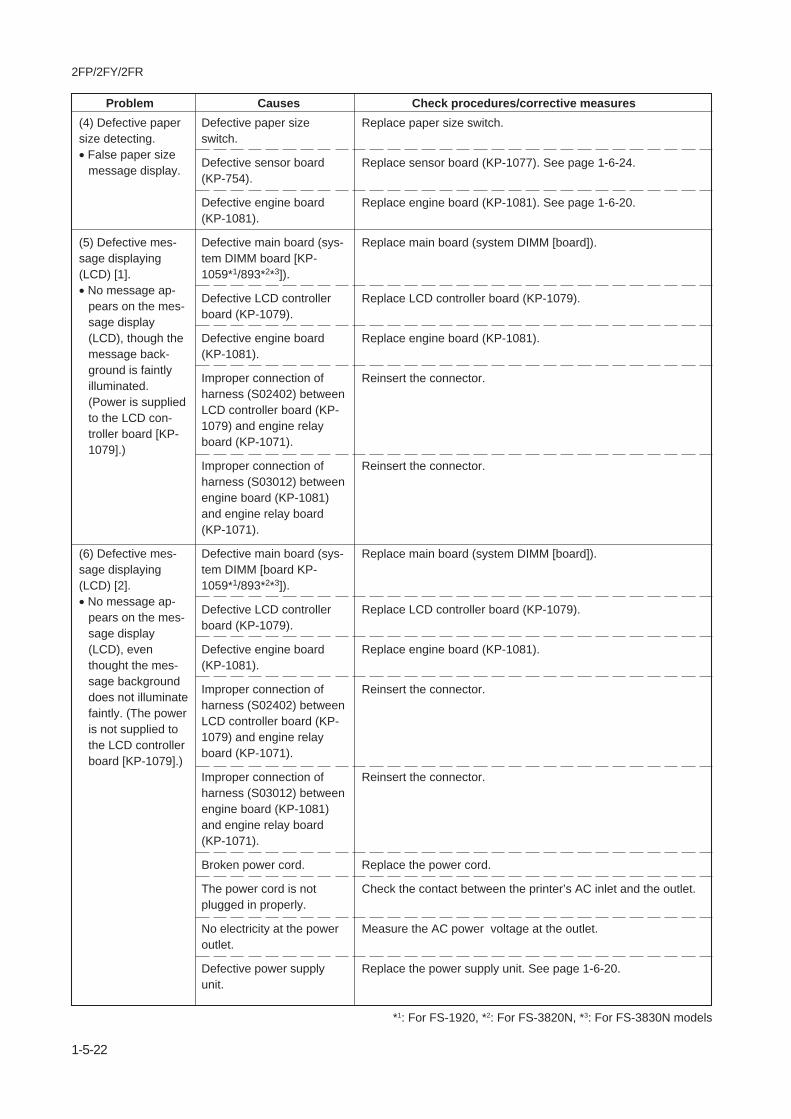
2FP/2FY/2FR
1-5-22
Problem Causes Check procedures/corrective measures
*1: For FS-1920, *2: For FS-3820N, *3: For FS-3830N models
(4) Defective papersize detecting.• False paper size
message display.
(5) Defective mes-sage displaying(LCD) [1].• No message ap-
pears on the mes-sage display(LCD), though themessage back-ground is faintlyilluminated.(Power is suppliedto the LCD con-troller board [KP-1079].)
(6) Defective mes-sage displaying(LCD) [2].• No message ap-
pears on the mes-sage display(LCD), eventhought the mes-sage backgrounddoes not illuminatefaintly. (The poweris not supplied tothe LCD controllerboard [KP-1079].)
Defective paper sizeswitch.
Defective sensor board(KP-754).
Defective engine board(KP-1081).
Defective main board (sys-tem DIMM board [KP-1059*1/893*2*3]).
Defective LCD controllerboard (KP-1079).
Defective engine board(KP-1081).
Improper connection ofharness (S02402) betweenLCD controller board (KP-1079) and engine relayboard (KP-1071).
Improper connection ofharness (S03012) betweenengine board (KP-1081)and engine relay board(KP-1071).
Defective main board (sys-tem DIMM [board KP-1059*1/893*2*3]).
Defective LCD controllerboard (KP-1079).
Defective engine board(KP-1081).
Improper connection ofharness (S02402) betweenLCD controller board (KP-1079) and engine relayboard (KP-1071).
Improper connection ofharness (S03012) betweenengine board (KP-1081)and engine relay board(KP-1071).
Broken power cord.
The power cord is notplugged in properly.
No electricity at the poweroutlet.
Defective power supplyunit.
Replace paper size switch.
Replace sensor board (KP-1077). See page 1-6-24.
Replace engine board (KP-1081). See page 1-6-20.
Replace main board (system DIMM [board]).
Replace LCD controller board (KP-1079).
Replace engine board (KP-1081).
Reinsert the connector.
Reinsert the connector.
Replace main board (system DIMM [board]).
Replace LCD controller board (KP-1079).
Replace engine board (KP-1081).
Reinsert the connector.
Reinsert the connector.
Replace the power cord.
Check the contact between the printer’s AC inlet and the outlet.
Measure the AC power voltage at the outlet.
Replace the power supply unit. See page 1-6-20.

2FP/2FY/2FR
1-5-23
Problem Causes Check procedures/corrective measures(7) Defective faceup/down solenoidoperating.• Change guide
does not operatein the fuser unit.
(8) False “Close pa-per transfer unit”.
(9) False “Close topcover”.
Improper insertion of theface up/down solenoidconnector into fuser board(KP-1069).
Broken face up/down sole-noid coil or blown-out fuse(ICP831) on the fuserboard (KP-1069).
Defective engine board(KP-1081) or power supplyunit.
Reinsert the connector.
Remove and then check for continuity across the face up/downsolenoid connector terminals; pin #1 and pin #2, pin #3 and pin#2. Remove and check for continuity of fuser board (KP-1069)connectors terminals; across the pin #2 of connector (YC832)and pin #2 of connector (YC831). If none, replace the face up/down solenoid and fuser board (KP-1069) at the same time. Orreplace fuser unit.See page 1-6-27.
Replace engine board (KP-1081) or power supply unit. See page1-6-20.
Measure voltage #12 pin of YC701 on sensor board (KP-1077).
Connect circuit tester to pin #20 of YC4 on engine board (KP-1081).
Yes
Yes
No
No
Replace engine board (KP-1081). See page 1-6-20.
Replace sensor board (KP-1077). See page 1-6-24.
When paper feed unit
close securely, does pin #12 voltage change
0 to 24 V DC?
Replace sensor board (KP-1077). See page 1-6-24.
When paper transfer unit
close securely, does pin #20 voltage change
0 to 24 V DC?
START
Measure logic level #11 pin of YC701 on sensor board (KP-1077). Yes
No
Replace engine board (KP-1081). See page 1-6-20.
Replace sensor board (KP-1077). See page 1-6-24.
When Top cover
close scurely, does pin #11 goes low
to high?
START

2FP/2FY/2FR
1-5-24
Check if the surfaces of the following rollersare dirty with paper powder: pickup roller,feed roller, and MP tray feed roller.
Check if the pickup roller, feed roller, andMP tray feed roller are deformed.
Electrical problem with the following electro-magnetic clutch (solenoid): feed clutch, andMP feed solenoid.
Check if the surfaces of the upper and lowerregistration rollers are dirty with paper pow-der.
Electrical problem with the registrationclutch.
Check if the paper is curled.
Check if the paper is excessively curled.
Deformed guides along the paper conveyingpath.
Check if the contact between the upper andlower registration rollers is correct.
Check if the press roller is extremely dirty ordeformed.
Check if the contact between the heat rollerand its separation claws is correct.
Check if the developing section of the imageformation unit is extremely dirty.
Check if the pulleys, rollers and gears oper-ate smoothly.
Check if the following electromagneticclutches (solenoid) are installed correctly:feed clutch, registration clutch, middleclutch, and MP feed solenoid.
Problem Causes/check procedures Corrective measures
1-5-5 Mechanical problems
(1)No primary paper feed.
(2)No secondary paperfeed.
(3)Skewed paper feed.
(4)Multiple sheets of paperare fed at one time.
(5)Paper jams.
(6)Toner drops on the pa-per conveying path.
(7)Abnormal noise isheard.
Clean with isopropyl alcohol.
Check visually and replace any deformedrollers (see page 1-6-11 and 1-6-14).
Check visually and replace any deformedelectromagnetic clutch.
Clean with isopropyl alcohol.
Check visually and replace any deformedregistration clutch.
Change the paper.
Change the paper.
Check visually and replace any deformedguides.
Check visually and remedy if necessary.Replace the pressure spring if it is de-formed.
Clean or replace the press roller.
Repair if any springs are off the separationclaws.
Clean the developing section of the imageformation unit.
Grease the bearings and gears.
Correct.

2FP/2FY/2FR
1-6-1
1-6-1 Precautions for assembly and disassembly
(1) Precautions• Be sure to turn the power switch off and disconnect the power plug before starting disassembly.• When handling PWBs (printed wiring boards), do not touch parts with bare hands. The PWBs are susceptible to static
charge.• Do not touch any PWB containing ICs with bare hands or any object prone to static charge.• Use only the specified parts to replace the fixing unit thermal cutout. Never substitute electric wires, as the printer may
be seriously damaged.• Use the following circuit testers when measuring voltages:
Hioki 3200Sanwa MD-180CSanwa YX-360TRBeckman TECH300Beckman DM45Beckman 330*Beckman 3030*Beckman DM850*Fluke 8060A*Arlec DMM1050Arlec YF1030C* Capable of measuring RMS values.
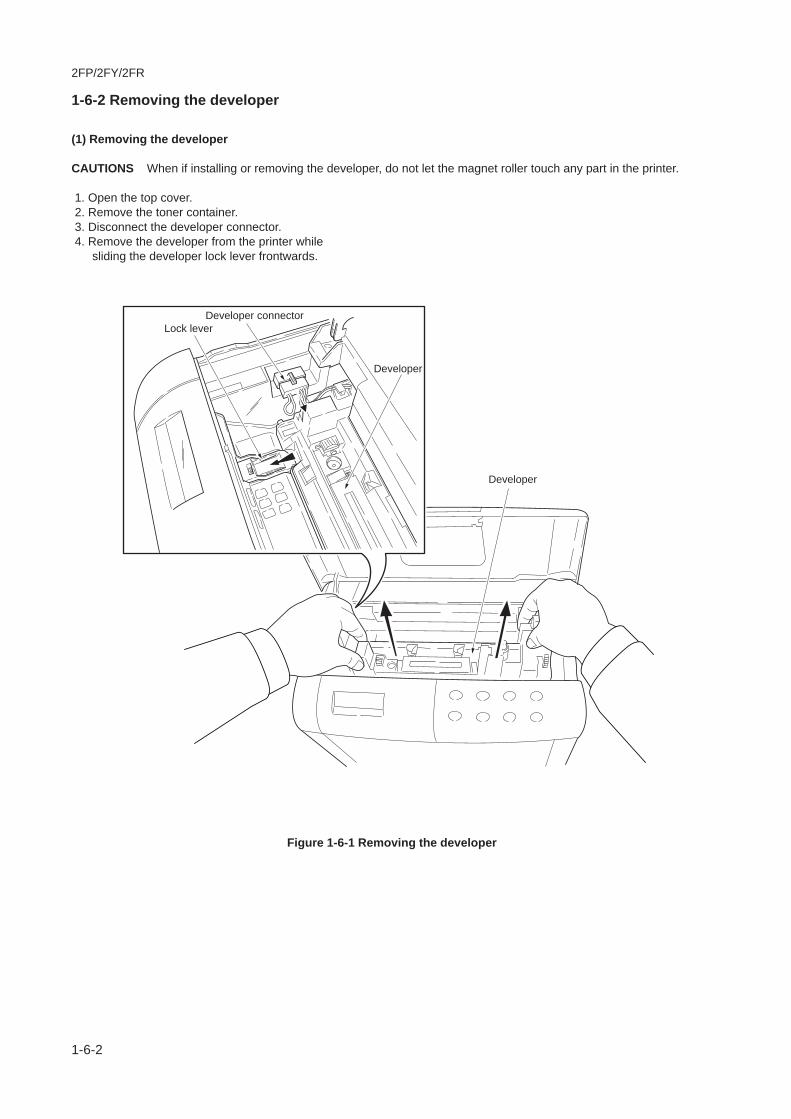
2FP/2FY/2FR
1-6-2
1-6-2 Removing the developer
(1) Removing the developer
CAUTIONS When if installing or removing the developer, do not let the magnet roller touch any part in the printer.
1. Open the top cover. 2. Remove the toner container. 3. Disconnect the developer connector. 4. Remove the developer from the printer while
sliding the developer lock lever frontwards.
Figure 1-6-1 Removing the developer
Developer connector
Developer
Developer
Lock lever

2FP/2FY/2FR
1-6-3
5. Gently flip down the magnet roller protectivecover.
Figure 1-6-2 Closing the magnet roller protective cover
NOTE After removing the developer, seal it in the protective bag and place it on a flat surface. Do not place thedeveloper in a dusty area. If you ship the developer, pack it in the shipping container specifically suppliedwith the printer. See page 1-4-13.
Magnet roller protective cover
Magnet roller

2FP/2FY/2FR
1-6-4
1-6-3 Removing the paper transfer unit
1. Draw the paper transfer unit while pressing thebuttons in the direction of arrow (A).
Figure 1-6-3 Removing the paper transfer unit
Paper transfer unit
(A)

2FP/2FY/2FR
1-6-5
1-6-4 Removing the main charger unit
1. Pull the main charger unit upwards whilepushing main charger release lever. Then,pull the main charger unit frontwards.
Figure 1-6-4 Removing the main charger unit
Main charger release lever
Main charger unit
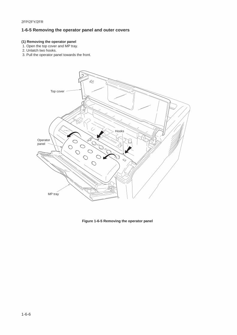
2FP/2FY/2FR
1-6-6
1-6-5 Removing the operator panel and outer covers
(1) Removing the operator panel 1. Open the top cover and MP tray. 2. Unlatch two hooks. 3. Pull the operator panel towards the front.
Figure 1-6-5 Removing the operator panel
Operatorpanel
MP tray
Top cover
Hooks
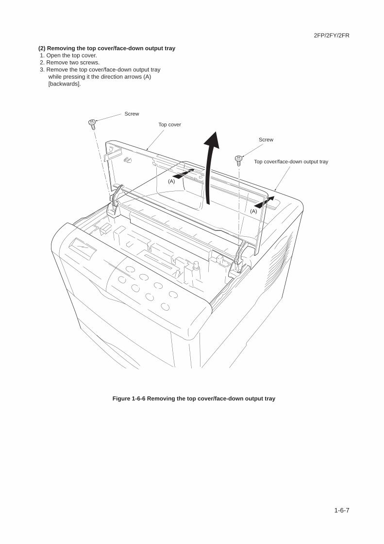
2FP/2FY/2FR
1-6-7
(2) Removing the top cover/face-down output tray 1. Open the top cover. 2. Remove two screws. 3. Remove the top cover/face-down output tray
while pressing it the direction arrows (A)[backwards].
Figure 1-6-6 Removing the top cover/face-down output tray
Screw
Screw
Top cover
Top cover/face-down output tray
(A)
(A)

2FP/2FY/2FR
1-6-8
(3) Removing the right cover 1. Remove the operator panel. See page 1-6-6. 2. Unlatch the four snaps (A) and three hooks (B)
on the chassis. Remove the right cover.
Figure 1-6-7 Removing the right cover
(A)
(A)
(A)
(B)
(B)
(B)
(A)
Right cover

2FP/2FY/2FR
1-6-9
(4) Removing the left cover 1. Unlatch the four snaps (A) and three hooks (B)
on the chassis. Remove the left cover.
Figure 1-6-8 Removing the left cover
(A)
(B)
(B)
(A)
(A)
(B)
Left cover
(A)

2FP/2FY/2FR
1-6-10
1-6-6 Removing the drum unit
1. Remove the paper cassette and the papertransfer unit. See page 1-6-4.
2. Remove the developer unit. See page 1-6-2. 3. Remove the waste toner bottle. 4. Remove the drum unit while pressing the drum
lock.
Figure 1-6-9 Removing the drum unit
Drum unit
Drum lock

2FP/2FY/2FR
1-6-11
1-6-7 Removing the pickup roller and feed roller
1. Remove the paper transfer unit. See page 1-6-4.
2. Turn the paper transfer unit over. 3. Detach the release holder by sliding it while
pressing the projections. 4. Remove the feed roller assembly while pressing
it in the direction of arrow (A).
Figure 1-6-10 Removing the feed roller assembly
Projection
Projection
Feed rollerassembly
Release holder
(A)
Paper transfer unit

2FP/2FY/2FR
1-6-12
5. Remove the feed bracket cover whileunlatching three snaps.
6. Remove the pickup roller and the feed roller.
Figure 1-6-11 Remove the pickup roller and feed roller
CAUTIONS Pickup gear Z32S is installed of the inside the one way clutch. When refitting pickup gear Z32S, face theone way clutch face to the feed bracket cover.
Feed bracket cover
Snap
Snap
SnapPickup gear Z32S
One wayclutch
Pickup roller
Feed roller
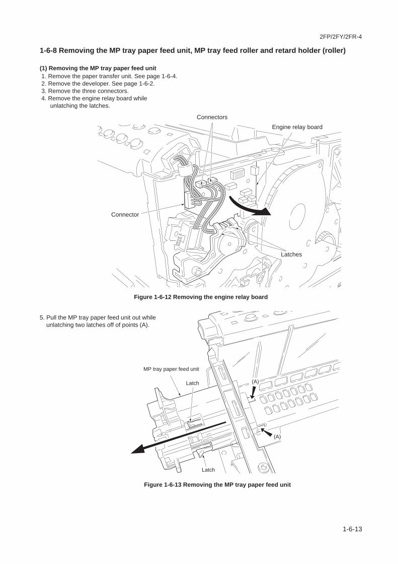
2FP/2FY/2FR-4
1-6-13
1-6-8 Removing the MP tray paper feed unit, MP tray feed roller and retard holder (roller)
(1) Removing the MP tray paper feed unit 1. Remove the paper transfer unit. See page 1-6-4. 2. Remove the developer. See page 1-6-2. 3. Remove the three connectors. 4. Remove the engine relay board while
5. Pull the MP tray paper feed unit out while unlatching two latches off of points (A).
unlatching the latches.
Figure 1-6-12 Removing the engine relay board
Figure 1-6-13 Removing the MP tray paper feed unit
Connectors
Connector
Latches
Engine relay board
MP tray paper feed unit
Latch
(A)
(A)
Latch
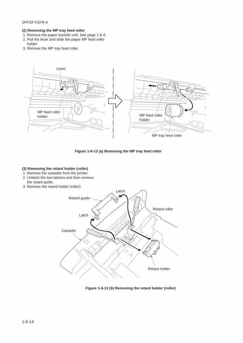
2FP/2FY/2FR-4
1-6-14
(2) Removing the MP tray feed roller 1. Remove the paper transfer unit. See page 1-6-4. 2. Pull the lever and slide the paper MP feed roller holder. 3. Remove the MP tray feed roller.
(3) Removing the retard holder (roller) 1. Remove the cassette from the printer. 2. Unlatch the two latches and then remove the retard guide. 3. Remove the retard holder (roller).
Figure 1-6-13 (a) Removing the MP tray feed roller
Figure 1-6-13 (b) Removing the retard holder (roller)
Lever
MP tray feed roller
Retard guide
Cassette
Latch
Latch
Retard roller
Retard holder
MP feed rollerholder MP feed roller
holder

2FP/2FY/2FR
1-6-15
1-6-9 Removing the transfer roller
CAUTIONS Do not touch the transfer roller (sponge) surface. Oil and dust (particles of paper, etc.) on the transfer rollercan significantly deteriorate the print quality (white spots, etc.).
1. Draw the paper transfer unit from the printer. 2. Remove the paper chute. 3. Remove the transfer roller.
Figure 1-6-14 Removing the transfer roller
Paper chute
Transfer roller

2FP/2FY/2FR
1-6-16
1-6-10 Removing the controller unit and the principal circuit boards
(1) Removing and opening the controller unit 1. Remove the top cover/face-down output tray.
See page 1-6-7. 2. Remove the right and left covers. See page 1-
6-8 and 1-6-9. 3. Remove the four connectors and one tab from
the controller unit left side.
Figure 1-6-15 Removing the connectors and tab from controller unit left side
CAUTIONS Draw the connector straight to remove. If you draw the connector while it is slanted, the receptacle may bedamaged.
Connector
Receptacle
Controller unit
Connectors
Tab
Connectors

2FP/2FY/2FR
1-6-17
4. Remove the two connectors from thecontroller unit right side.
Figure 1-6-16 Removing the connectors from controller unit right side
Connector
Receptacle
Connectors
Controller unit

2FP/2FY/2FR
1-6-18
5. Remove three screws. 6. Remove frame unit while releasing the
projections from the catches on the frameunit.
Figure 1-6-17 Removing the controller unit form the frame unit
Frame unit
ScrewScrew
Screw

2FP/2FY/2FR
1-6-19
7. Remove two screws. 8. Remove the main board. 9. Remove four screws.10. Remove the grounding terminal and controller
unit lid from the controller unit.
Figure 1-6-18 Opening the controller unit
Main board
Screw
Screw
Controller unit
Controller unit lid
ScrewScrew
Grounding terminal
ScrewScrew

2FP/2FY/2FR
1-6-20
(2) Removing the engine board and power supply unit 1. Remove and open the controller unit. See
pages 1-6-19. 2. Remove the connectors YC3 and YC6 from
the engine board. 3. Remove the connector YC10 from the engine
board. (For FS-3820N/3830N models only) 4. Remove five screws. 5. Remove the engine board.
Figure 1-6-19 Removing the engine board
Screws
Screws
Engine board
Connector(YC3) Connector
(YC6)
Connector(YC10)

2FP/2FY/2FR
1-6-21
6. Remove the power switch rod. 7. Remove one screw, grounding wire terminal,
and lock washer. 8. Remove three screws. 9. Remove the power supply unit from the power
supply unit cover.
Screw
Screws
Lock washer
Grounding wire terminal
Power supply unitPower switch rod
Power supply unit cover
Figure 5-2-20 Removing the power supply unit
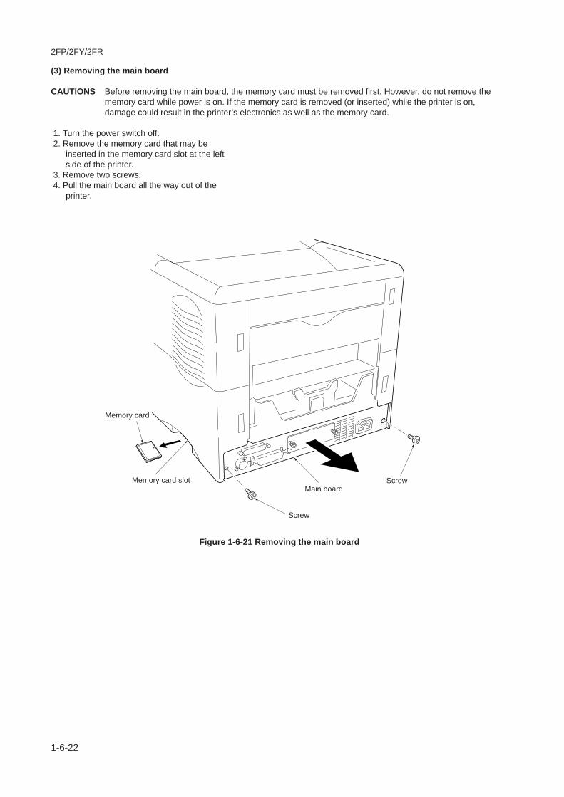
2FP/2FY/2FR
1-6-22
(3) Removing the main board
CAUTIONS Before removing the main board, the memory card must be removed first. However, do not remove thememory card while power is on. If the memory card is removed (or inserted) while the printer is on,damage could result in the printer’s electronics as well as the memory card.
1. Turn the power switch off. 2. Remove the memory card that may be
inserted in the memory card slot at the leftside of the printer.
3. Remove two screws. 4. Pull the main board all the way out of the
printer.
Main board
Screw
ScrewMemory card slot
Memory card
Figure 1-6-21 Removing the main board

2FP/2FY/2FR
1-6-23
(4) Removing the high voltage unit 1. Remove the top cover and left covers. See
pages 1-6-7 and 1-6-9. 2. Remove the high voltage unit while unlatching
two latches. 3. Remove two connectors from the high voltage
unit.
Figure 1-6-22 Removing the high voltage unit
Connector
Connector
Latch
Latch
High voltage unit

2FP/2FY/2FR-2
1-6-24
(5) Removing the sensor board
CAUTIONS Draw the connector straight to remove. If you draw the connector while it is slanted, the receptacle may bedamaged.
1. Remove the drum unit. See page 1-6-10. 2. Remove the high voltage unit. See previous
page. 3. Remove two connectors. 4. Remove the high voltage unit cover. 5. Remove the sensor board while unlatching
two latches.
Figure 1-6-23 Removing the sensor board
High voltage unit cover
Sensor board
Latch
Latch
Connector
Connector
Connector
Connector
Receptacle
Receptacle
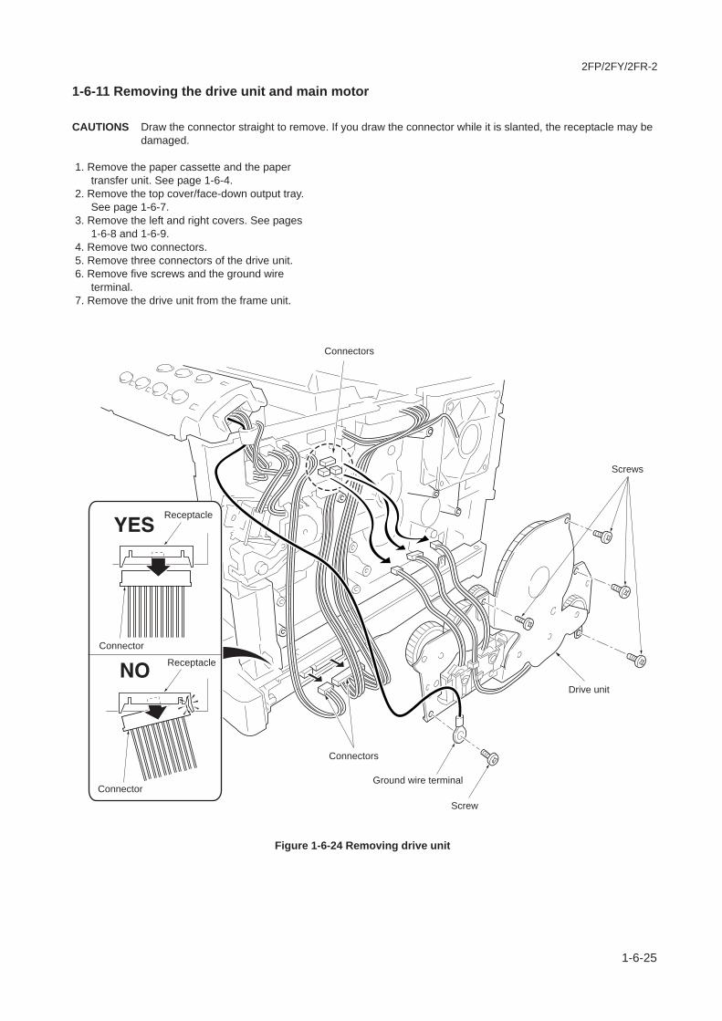
2FP/2FY/2FR-2
1-6-25
1-6-11 Removing the drive unit and main motor
CAUTIONS Draw the connector straight to remove. If you draw the connector while it is slanted, the receptacle may bedamaged.
1. Remove the paper cassette and the papertransfer unit. See page 1-6-4.
2. Remove the top cover/face-down output tray.See page 1-6-7.
3. Remove the left and right covers. See pages1-6-8 and 1-6-9.
4. Remove two connectors. 5. Remove three connectors of the drive unit. 6. Remove five screws and the ground wire
terminal. 7. Remove the drive unit from the frame unit.
Figure 1-6-24 Removing drive unit
Connector
Connectors
Connector
Receptacle
Receptacle
Screw
Ground wire terminal
Screws
Drive unit
Connectors
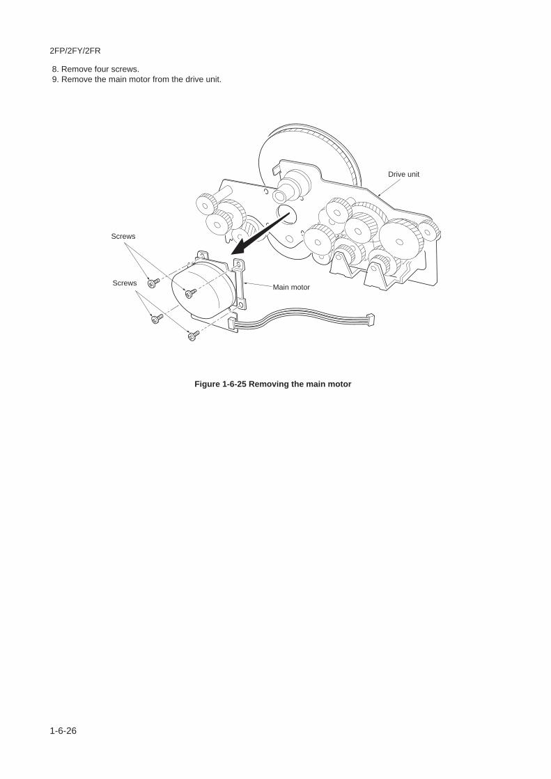
2FP/2FY/2FR
1-6-26
8. Remove four screws. 9. Remove the main motor from the drive unit.
Figure 1-6-25 Removing the main motor
Screws
Screws Main motor
Drive unit
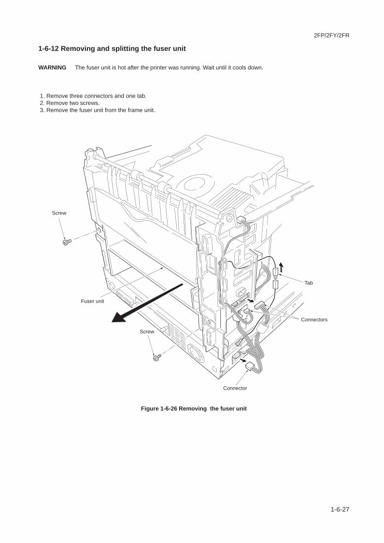
2FP/2FY/2FR
1-6-27
1-6-12 Removing and splitting the fuser unit
WARNING The fuser unit is hot after the printer was running. Wait until it cools down.
1. Remove three connectors and one tab. 2. Remove two screws. 3. Remove the fuser unit from the frame unit.
Figure 1-6-26 Removing the fuser unit
Screw
Screw
Connector
Connectors
Tab
Fuser unit

2FP/2FY/2FR
1-6-28
4. Remove the rear cover and the spring. 5. Remove the solenoid actuator. 6. Remove the change guide. 7. Remove one connector.
Figure 1-6-27 Removing the rear cover and change guide
ConnectorSolenoidactuator
Rear cover
Spring
Change guide

2FP/2FY/2FR
1-6-29
8. Remove two screws. 9. Split the fuser unit.
Figure 1-6-28 Splitting the fuser unit
Screw
ScrewFuser unit
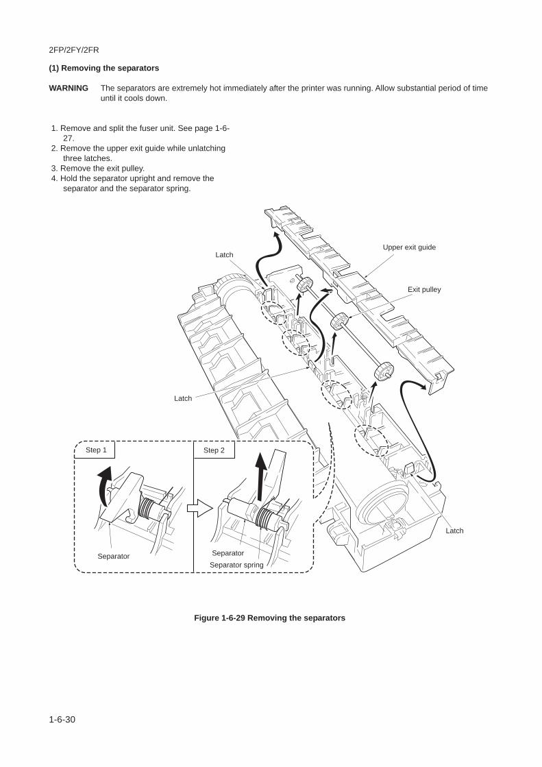
2FP/2FY/2FR
1-6-30
(1) Removing the separators
WARNING The separators are extremely hot immediately after the printer was running. Allow substantial period of timeuntil it cools down.
1. Remove and split the fuser unit. See page 1-6-27.
2. Remove the upper exit guide while unlatchingthree latches.
3. Remove the exit pulley. 4. Hold the separator upright and remove the
separator and the separator spring.
Figure 1-6-29 Removing the separators
Step 1 Step 2
SeparatorSeparator spring
Separator
Latch
Latch
LatchUpper exit guide
Exit pulley

2FP/2FY/2FR
1-6-31
(2) Removing the heater lamp
WARNING The heater lamp is extremely hot immediately after the printer was running. Allow substantial period oftime until it cools down.
CAUTIONS The heater lamps are fragile. Use extreme care when handling not to drop or break.Do not directly touch on the heater lamp. Finger prints on the heater lamp’s outer surface can preventproper fusing of toner on paper. When holding the heater lamp, hold the ceramic parts of heater lamp atboth ends.When refitting the heater lamp, direct the wattage making side facing the heat gear Z36 side.
1. Remove and split the fuser unit. See page 1-6-27.
2. Remove the lamp support. 3. Remove two screws and heater wire terminal. 4. Remove the heater lamp from the heat roller.
Figure 1-6-30 Removing the heater lamp
Screw
Heater lamp
Heat roller
Heater wireterminal
Heat gear Z36
Screw Wattage marking
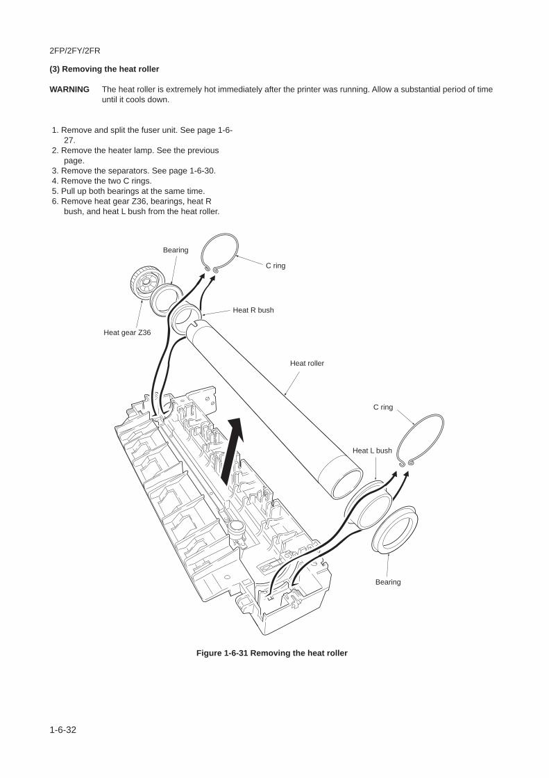
2FP/2FY/2FR
1-6-32
(3) Removing the heat roller
WARNING The heat roller is extremely hot immediately after the printer was running. Allow a substantial period of timeuntil it cools down.
1. Remove and split the fuser unit. See page 1-6-27.
2. Remove the heater lamp. See the previouspage.
3. Remove the separators. See page 1-6-30. 4. Remove the two C rings. 5. Pull up both bearings at the same time. 6. Remove heat gear Z36, bearings, heat R
bush, and heat L bush from the heat roller.
Figure 1-6-31 Removing the heat roller
Heat gear Z36
Bearing
Heat R bush
Bearing
Heat roller
Heat L bush
C ring
C ring

2FP/2FY/2FR
1-6-33
(4) Removing the thermistor and the thermal cutout 1. Remove and split the fuser unit. See page 1-6-
27. 2. Remove the heater lamp. See page 1-6-31. 3. Remove the heat roller. See previous page. 4. Remove one screw. 5. Remove the thermistor. 6. Remove two screws and then remove cord
plate. 7. Remove one screw and the heater wire
terminal. 8. Remove the thermal cutout.
Figure 1-6-32 Removing the thermistor and thermal cutout
Screws
Screw
Heater wire terminal
Thermal cutout
Thermistor
Cord plate

2FP/2FY/2FR
1-6-34
(5) Removing the press roller
WARNING The press roller is extremely hot immediately after the printer was running. Allow substantial period of timeuntil it cools down.
1. Remove and split the fuser unit. See page 1-6-27.
2. Remove the press roller from the fuser unit.
Figure 1-6-33 Removing the press roller
Press roller
Fuser unit

2FP/2FY/2FR
1-6-35
1-6-13 Removing the laser scanner unit
1. Remove the top cover/face-down output tray.See pages 1-6-7.
2. Remove two connectors. 3. Remove four screws. 4. Remove the laser scanner unit from the frame
unit.
CAUTIONS When refitting the laser scanner unit, fix the four screws in the order indicated above.
Figure 1-6-34 Removing the laser scanner unit
2
3
4
Order of fixing the laser scanner unit
1
Screws
Screws
Laser scanner unit
Connectors

2FP/2FY/2FR-4
1-6-36
1-6-14 Replacing the ozone filter B and ozone filter
(1) Replacing the ozone filter B and ozone filter 1. Remove the top cover/face-down output tray.
See page 1-6-7. 2. Remove the right cover. See page 1-6-8. 3. Replace the ozone filter B.
4. Remove the two screws and then remove the cooling fan motor.
5. Replace the ozone filter.
Figure 1-6-35 Replacing the ozone filter B
Figure 1-6-36
Figure 1-6-37 Replacing the ozone filter
Ozone filter B
Ozone filter
Cooling fan motor
ScrewScrew
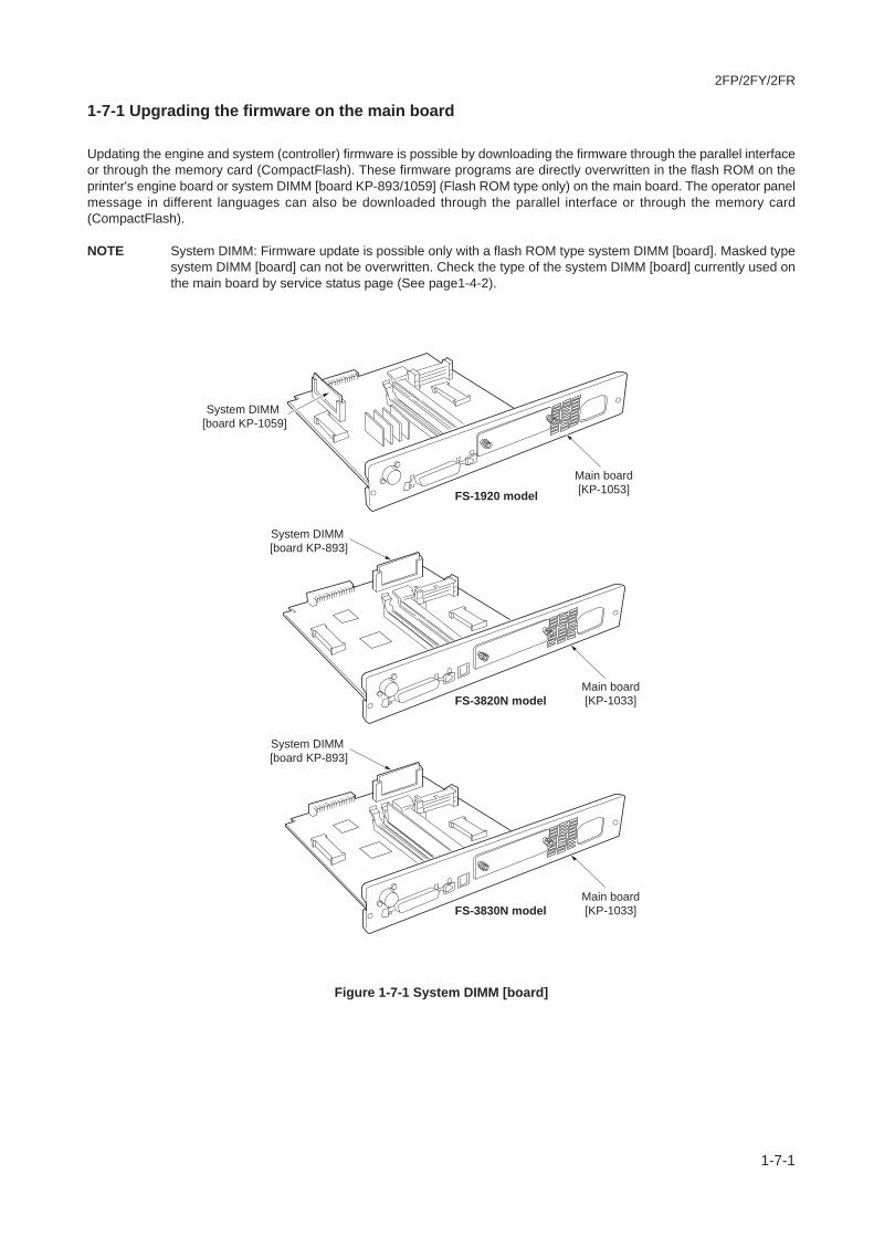
2FP/2FY/2FR
1-7-1
1-7-1 Upgrading the firmware on the main board
Updating the engine and system (controller) firmware is possible by downloading the firmware through the parallel interfaceor through the memory card (CompactFlash). These firmware programs are directly overwritten in the flash ROM on theprinter's engine board or system DIMM [board KP-893/1059] (Flash ROM type only) on the main board. The operator panelmessage in different languages can also be downloaded through the parallel interface or through the memory card(CompactFlash).
NOTE System DIMM: Firmware update is possible only with a flash ROM type system DIMM [board]. Masked typesystem DIMM [board] can not be overwritten. Check the type of the system DIMM [board] currently used onthe main board by service status page (See page1-4-2).
Figure 1-7-1 System DIMM [board]
Main board[KP-1033]
System DIMM [board KP-1059]
System DIMM [board KP-893]
Main board[KP-1053]
FS-3820N model
Main board[KP-1033]
System DIMM [board KP-893]
FS-3830N model
FS-1920 model
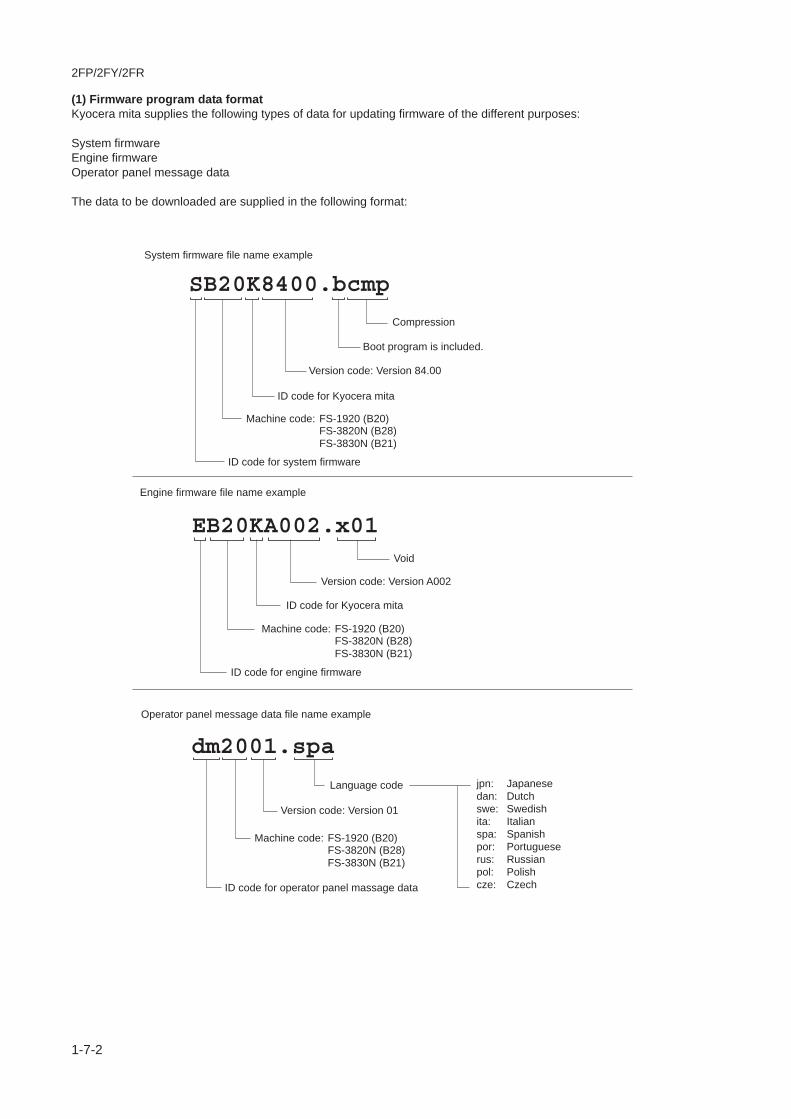
2FP/2FY/2FR
1-7-2
(1) Firmware program data formatKyocera mita supplies the following types of data for updating firmware of the different purposes:
System firmwareEngine firmwareOperator panel message data
The data to be downloaded are supplied in the following format:
SB20K8400.bcmp
Boot program is included.
ID code for Kyocera mita
ID code for Kyocera mita
EB20KA002.x01
dm2001.spa
jpn:dan:swe:ita:spa:por:rus:pol:cze:
JapaneseDutchSwedishItalianSpanishPortugueseRussianPolishCzech
Compression
Void
Version code: Version 84.00
Version code: Version A002
Version code: Version 01
ID code for engine firmware
ID code for system firmware
System firmware file name example
Engine firmware file name example
ID code for operator panel massage data
Operator panel message data file name example
Language code
Machine code:FS-3820N (B28)FS-3830N (B21)
FS-1920 (B20)
Machine code:FS-3820N (B28)FS-3830N (B21)
FS-1920 (B20)
Machine code:FS-3820N (B28)FS-3830N (B21)
FS-1920 (B20)

2FP/2FY/2FR
1-7-3
(2) Downloading the firmware from the parallel interface
This section explains how to download firmware data from the parallel interface. The printer system can automaticallyrecognize whether the data to be overwritten is for the engine firmware, the controller firmware or operator panel messagedata.
CAUTION Downloading the controller firmware takes several minutes. Do not turn power off during downloading.
NOTE MS-DOS is required for a downloading from the parallel interface. The computer must be connected to theprinter with a parallel cable.
1. Turn power switch on. 2. At the DOS prompt, send the command to the printer that engages the printer in the supervisor mode. 3. Copy the firmware data to the printer. (See the flow chart below) [System firmware ex. SB20KA8400.bcmp, Engine firmware ex. EB20KA002.x01, Operator panel message data ex.
dm2001.spa]
Message display
PC display
Self test
>Supervisor modeParallel waiting
>ECHO !R!UPGR'SYS';EXIT;>PRN
Power switch: On
>COPY/B SB20K8200.bcmp PRN>COPY/B EB20KA002.x01 PRN>COPY/B dm2001.spa PRN
SEM
1.
Start
2.
3.
Ready
To the next page
: System firmware: Engine firmware: Operator panel message data
SEM

2FP/2FY/2FR
1-7-4
4. Supervisor mode. The parallel interface is waiting for the firmware data. 5. Receiving the firmware data. 6. The system DIMM or flash ROM is overwritten with the new firmware data. 7. Firmware downloading is finished. (When more than one data are down loaded, the data display can be changed by
pressing any key.) 8. Turn power switch off and on. 9. Check the that printer gets Ready.
Confirm that the status page shows the new engine firmware, system firmware or operator panel message data version(See page 1-4-2). If the message display indicates download error, refer to section "Downloading errors" on page 1-7-7.
data receiving>>>>>>>>>>>
BootROMerase&write
engine download<<<<<<<<<<<
message download<<<<<<<<<<<
DIMM erasing #??
Ready
Power switch: Off/On
: System firmware: Engine firmware: Operator panel message data
Spanish 0404/01/18[1234] 2
B
A
BB GC
E FE F E F
DG G
20 A00204/01/18[1234] 2
84.00S04/01/18[1234] 2
A: u= Extracting W= Writing V= Verifying B: Version C: Machine codeD: LanguageE: Year/Month/DayF: [Checksum]G: Means more than one data
End
DIMM writing<<<<<<<<<<u
S
S
E
E
M
M
7. 7. 7.
8.
9.
4.
5.
6. 6. 6.
: Shows only included firmwareof boot program (".bcmp" extension file).
From the previous page
Supervisor modeparallel waiting
Message display

2FP/2FY/2FR
1-7-5
(3) Downloading the firmware from the memory card
To download data written in a memory card (CompactFlash) to the printer, proceed as explained inthis section.
CAUTION Downloading firmware takes several minutes. Do not turn power off during downloading. If downloading isinterrupted by an accidental power failure, etc., the system DIMM may have to be replaced.
NOTE The firmware program data must be stored to the root directory of the memory card (CompactFlash).
1. Turn power switch off. 2. Insert the memory card in the printer's memory card slot. 3. Turn power switch on. 4. The printer is automatically engaged in the supervisor mode. The parallel interface receives for the firmware data.
Message display
Self test
Power switch: On3
Power switch: Off
Start
1
2
To the next page
Memory card

2FP/2FY/2FR
1-7-6
5. Data are transferred to the RAM on the main board. 6. The system DIMM or Flash ROM is overwritten with the new firmware data. 7. Firmware download is finished. (When more than one data are down loaded, the data display can be changed by
pressing any key. 8. Turn power switch off. 9. Remove the memory card.10. Turn power switch on.11. Check the printer gets Ready.
Confirm that the status page shows the new engine firmware, system firmware or operator panel message data version(See page 1-4-2). If the message display indicates download error, refer to section "Downloading errors" on page 1-7-7.
Supervisor modeCF-CARD Reading
BootROMerase&write
engine download<<<<<<<<<<<
message download<<<<<<<<<<<
DIMM erasing #??
Ready
Power switch: Off
Power switch: On
Spanish 0404/01/18[1234] 2
B
A
BB GC
E FE F E F
DG G
20 A00204/01/18[1234] 2
84.00S04/01/18[1234] 2
A: u= Extracting W= Writing V= Verifying B: Version C: Machine codeD: LanguageE: Year/Month/DayF: [Checksum]G: Means more than one data
End
DIMM writing<<<<<<<<<<u
S E M
7. 7. 7.
8.
11.10.
4.
5.
6. 6. 6.
Memory card
9.
From the previous page
Supervisor mode
Message display: System firmware: Engine firmware: Operator panel message data
SEM
: Shows only included firmwareof boot program (".bcmp" extension file).

2FP/2FY/2FR
1-7-7
(4) Downloading errors
The following messages are indicated on the message display when an error occurred during downloading the firmwaredata.
If the corrective action above does not solve the problem, replace engine board (KP-1081). See page 1-6-20.
##: Error code 20 to 26.
##: Error code 40 to 59.
##: Error code 80 or 81.
##: Error code 60 or 69.
##: Error code 70 or 77.
Deficit of the file header
Deficit of the data header
File checksum error
Data checksum error
File header version error
Data header version error
Incompatibility of firmware andsystem DIMM board
Defective system DIMM board
Improper connection of parallelcable between PC and printer
Defective parallel cable
Improper connection of parallelcable between PC and printer
Incompatibility of firmware and en-gine board
Improper connection of parallelcable between PC and printer
Defective LCD controller board
Obtain the correct firmware.
Confirm whether the firmware is applicable tothis printer.
Replace the system DIMM board.
Check the contact between PC and the printer'sinterface connector.
Replace the parallel cable.
Check the contact between PC and the printer'sinterface connector.
Confirm whether the firmware conforms to thisprinter.
Check the contact between PC and the printer'sinterface connector.
Replace the LCD controller board
Error message Description Corrective action
download header
error [##]
system download
error [##]
receive
error [##]
Engine download
error [##]
Message download
error [##]

2FP/2FY/2FR
1-7-8
This page is intentionally left blank.

2FP/2FY/2FR
2-1-1
2-1-1 Paper feeding system
The paper feeding system picks up paper from the paper cassette, MP tray, or if installed, the paper feeder PF-60, feedsit in the printer and delivers in the output tray. Paper is feed at the precise timing in synchronization with data processing.The paper feeding system finally delivers the printed page to either the face-down or face-up output tray as manipulatedby the user.
(1) Paper feeding system
The figure below shows the components in the paper feeding system and the paths through which the paper travels. Thesensors, clutches, solenoids, motor etc., are described in the following pages.
Figure 2-1-1 Paper feeding components
56
87
9
1011
12
13
14
16
17
18
19
20
4
3
21
Paper from optionalpaper feeder PF-60or duplexer DU-61
15
1. Middle feed roller 2. MP tray feed roller 3. Guide pulley(s) 4. MP tray 5. Paper cassette 6. Feed pulley 7. Retard roller 8. Feed roller 9. Pickup roller10. Upper registration roller
11. Lower registration roller12. Transfer roller13. Drum14. Press roller15. Heat roller16. Exit roller17. Exit pulley(s)18. FD roller19. Pinch roller(s)20. Face-down output tray

2FP/2FY/2FR
2-1-2
(2) Paper feed controlThe following diagram shows interconnectivity of the feeding system components including the sensors and rollers. Theengine board issues various signals in synchronization with the electrophotographic process that is executed by the mainboard.
Figure 2-1-2 Paper feed control
Toner container
MP tray
Paper cassette
Fuser unit
Drum unit
Laser scanner unit
Developer
RE
GD
R*
MID
DR
*
MP
FSO
L*
FDD
R*
RE
GPA
P
PV
OLA
N2
PV
OLA
N1
HA
ND
S*
FDP
FUL*
EX
ITPA
P*
Fuser board
Power supply unitM
MO
TON
*
: Power train
FUD
R
FDD
RY
C2-
3
YC
2-4
YC
2-2
YC
2-6
YC
4-17
YC
4-22
YC
4-18
YC
7-16
YC
7-15
YC
5-13
YC
7-11
YC
7-5
YC
7-3
Sensorboard
Engine relay board High voltage unit
6
11 0 3
9
87
2
4
5
Engine board
1
1. Main motor 2. MP tray paper sensor 3. Registration sensor 4. Paper gauge sensor 1, 2 5. Exit sensor 6. Paper full sensor 7. MP tray feed solenoid 8. Middle feed clutch 9. Feed clutch10. Registration clutch11. Face up/down solenoid

2FP/2FY/2FR
2-1-3
(3) Paper feeding mechanism
Drive and paper transfer unit
Figure 2-1-3 Drive and paper transfer unit
To fuser unit
Drive unit
Paper transfer unit
Power train
8
1
2 3
4
5
AB
AB
67
1. Main motor 2. Registration clutch 3. Feed clutch 4. Pickup roller 5. Feed roller 6. Lower registration roller 7. Upper registration roller 8. Transfer roller

2FP/2FY/2FR
2-1-4
MP tray paper feed unit
Figure 2-1-4 MP tray paper feed unit
Drive unit
MP tray paper feed unit
MP tray
To paper transfer unit
DPower train
9
11
C
12
10
CD
9. Middle feed clutch10. MP tray feed solenoid11. MP tray feed roller12. Middle feed roller

2FP/2FY/2FR
2-1-5
Fuser unit and face up/down output
Figure 2-1-5 Fuser unit and face up/down output
To face-downoutput tray
To face-upoutput tray or option device
14
15
16
19
18
13
F Drive unit
Power train
Paper from paper transfer unit
FD gear bracket
Fuser unit
F
13. Heat roller14. Press roller15. Exit roller16. Exit pulley(s)17. FD roller18. Pinch roller(s)

2FP/2FY/2FR
2-1-6
2-1-2 Electrophotographic cycleThe electrophotographic system of the printer performs a cyclic action made of six steps as follows. Each step istechnically explained in the following sections.
Figure 2-1-6 Electrophotographic cycle
2 Exposure
3 Developing6 Cleaning
1 Main charging
4 Transfer
5 Fusing
Drum unitLaser scanner unit
Developer
Paper transfer unit
Fuser unit
Drum

2FP/2FY/2FR
2-1-7
(1) Main chargingComponents of drum and main charger unit
Figure 2-1-7 Components of drum and main charger unit
0
34
5 12
11
13
14
16
8
7
2
9Drum unit
Main charger unit
1. Eraser lamp [board] (KP-1067) 2. Zener board (KP-1073) 3. Drum board (KP-1064) 4. Waste toner full sensor [board] (KP-1065) 5. Waste toner full sensor (receiver) 6. Cleaning blade 7. Cleaning roller 8. Cleaner screw 9. Drum gear Z36H10. Drum11. Main charger shield12. Grid13. Main charger wire14. Charger wire cleaner

2FP/2FY/2FR
2-1-8
Amorphus-silicon drumThe printer use the long lasting amorphous silicon drum. The drum surface is a composite of five substances coated infive layers as shown below.
Figure 2-1-8 Amorphus silicon drum
The primary and secondary layers are for protecting the amorphous silicon layer underneath. The amorphus silicon layeris of photoconductive, meaning it can be electronically conductive when exposed to a (laser) light source to effectivelyground electrons charged on its outer surface to the ground. This layer is approximately 9 mm thick.
The carrier block layer lies between the amorphous silicon layer and the aluminum base cylinder and prevents thebackward electron flow, from the base cylinder to the drum’s outer surface, which might give adverse effect (possibly“ghost”) on the print quality.
12
34
5
Drum
1. Aluminum base 2. Carrier block (1 to 3 mm thick) 3. Photoconductor a-Si 4. Primary protection layer (1 mm thick) 5. Secondary protection layer

2FP/2FY/2FR
2-1-9
Charging the drumThe following shows a simplified diagram of the electrophotographic components in relation to the engine system.Charging the drum is done by the main charger wire.
Figure 2-1-9 Charging the drum
As the drum rotates in a “clean (neutral)” state, its photoconductive layer is given a uniform, positive (+) corona chargedispersed by the main charger wire. The grid regulates the main charging potential so that it is evenly and stablydispersed over the drum at a constant voltage level.
Due to being high-voltage scorotron charging, the main charger wire can get contaminated by oxidization after a long run.Therefore, it must be cleaned periodically from time to time using the charger wire cleaner (charger cleaning knob).Cleaning the main charger wire prevents print quality problems such as black streaks.
MCHON*
Main charging output Engine board
YC5-10
Main charger wire
Drum
Grid
High voltage unit
Zenerboard
KP-1073
M CN2-9

2FP/2FY/2FR
2-1-10
(2) ExposureThe charged surface of the drum is exposed to the laser beam scanning from the laser scanner unit.
Figure 2-1-10 Exposure
The polygon motor (with polygon mirrors) revolves (27,165 rpm) to reflect the laser beam over the drum. Lenses anddiversion mirror are housed in the laser scanner unit. These lenses adjust the diameter of the laser beam (670 nmwavelength) so that the laser beam effectively focalizes on the drum surface.
Drum
Laser scannerunit
Laser beamoutput
Polygon motor
LensLens
Diversion mirror

2FP/2FY/2FR-2
2-1-11
Laser scanner unit
Figure 2-1-11 Laser scanner unit
1. Laser diode .................................................. Emits diffused, visible laser. 2. Collimator lens ............................................. Aligns the laser beam to the cylindrical lens. 3. Cylindrical lens ............................................. Compensates the vertical angle at which the laser beam hits on of the
polygon mirror segments. 4. Polygon mirror (motor) ................................. Has six mirror segments around its hexagonal circumference. Each
mirror corresponds to one scanned line width on the drum when thelaser beam scans on it.
5. Primary f-theta lens ...................................... See figure 2-1-11 above. 6. Secondary f-theta lens ................................. The primary (above) and secondary f-theta lenses equalize focusing
distortion on the area on the drum closer to the edge. The effectivelength of line (A, B in the figure below) the laser beam draws on thedrum becomes longer as the laser beam hits closer to the drum edge. Inthe figure 2-1-11 above, distances represented by A and B are not thesame (A > B) until the f-theta lenses are provided between the polygonmirror and the drum (A = B).
7. Diversion mirror ............................................ Diverts the laser beam vertically onto the drum. Note the diffused laserbeam finally pinpoints on the drum.
8. Protective glass ............................................ Prevent dust, debris, etc., from entering the scanner assembly. 9. Sensor mirror ............................................... Bends the very first shot of a laser scan towards the pin photo sensor
(See figure 2-1-11).10. Pin photo sensor .......................................... When shone by the sensor mirror above, this pin photo sensor
generates a trigger signal.11. Heat sink ...................................................... Cooling polygon motor.
1
23
4
510
11
6
9
7
8
Primary f-theta lens
Laser diode
Polygon mirror
Drum
Laser beam
Secondary f-theta lens
Laser scanner unit (LSU)

2FP/2FY/2FR
2-1-12
Drum surface potential
The laser beam is continually switched on and off depending on the print data. It is on for a black (exposed) dot and offfor a white (blank) dot. Since the drum surface is evenly charged, whenever it is illuminated by the laser beam, theelectrical resistance of the photoconductor is reduced and the potential on the photoconductor is also lowered. Resultedon the drum surface is an electrostatic image which represents the data to print. Note that the area to be printed blackhas the low potential, constituting a “positively exposed” image.
Figure 2-1-12 Drum surface potential
Aluminum base
a-Si layer
Laser beam
Charged surface potential approx. +240 V
Exposed surface potentialapprox. 0 to +20 V
Drum

2FP/2FY/2FR
2-1-13
(3) Development
Figure 2-1-13 Developer mechanism
6
7
1
B
A
5
32
4
Toner container
Developer
B
A
Power train
1. Toner motor 2. Toner sensor 3. Developing roller 4. DLP A screw 5. DLP B screw 6. Blade 7. Magnet

2FP/2FY/2FR
2-1-14
The latent image constituted on the drum is developed into a visible image. The developing roller contains a 4-pole (S-N-S-N) magnet core and an aluminum cylinder rotating around the magnet core. Toner attracts to the developing rollersince it is powdery ink made of black resin bound to iron particles. The magnetic blade to which an auxiliary magnetpiece is attached is positioned approximately 0.3 to 0.4 mm above the developing roller. It constitutes a smooth layer oftoner in accordance with the revolution of the roller.
Figure 2-1-14 Development
The developing roller is applied with the AC-weighted, positive DC power source. Toner on the developing roller is givena positive charge. The positively charged toner is then attracted to the areas of the drum which was exposed to the laserlight. (The gap between the drum and the developing roller is approximately 0.3 mm.) The non-exposed areas of thedrum repel the positively charged toner as these areas maintain the positive charge. The developing roller is also AC-biased to ensure contrast in yielding by compensating the toner’s attraction and repelling action during development.
0.3 to 0.4 mm0.1 mm
Magnetism
Developing bias output
S
S
NN
NS
Magnet piece
Magnetic blade
Drum
Toner
Developing roller
Magnet core
HVCLK
High voltageunit
Engine board
YC5-8B CN2-11150 V DC + AC

2FP/2FY/2FR
2-1-15
A toner sensor is provided within the developer. As the toner supply from the toner container dwindles and the toner levellowers in the reservoir, the sensor translates it into an electrical signal through its diaphragm, urging the toner motor tofeed more toner.
Figure 2-1-15 Toner sensor
Toner
Toner hopper
Toner sensor
Developer
Diaphragm
Sensible level
Toner container
Toner motor
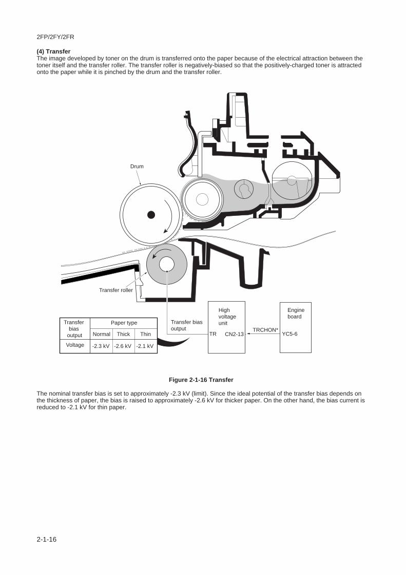
2FP/2FY/2FR
2-1-16
(4) TransferThe image developed by toner on the drum is transferred onto the paper because of the electrical attraction between thetoner itself and the transfer roller. The transfer roller is negatively-biased so that the positively-charged toner is attractedonto the paper while it is pinched by the drum and the transfer roller.
Figure 2-1-16 Transfer
The nominal transfer bias is set to approximately -2.3 kV (limit). Since the ideal potential of the transfer bias depends onthe thickness of paper, the bias is raised to approximately -2.6 kV for thicker paper. On the other hand, the bias current isreduced to -2.1 kV for thin paper.
S
S
N
Transfer roller
Drum
Voltage
Paper typeTransfer bias
output
Transfer bias output
High voltageunit
CN2-13TRTRCHON*
Engine board
YC5-6Normal
-2.3 kV
Thick
-2.6 kV
Thin
-2.1 kV
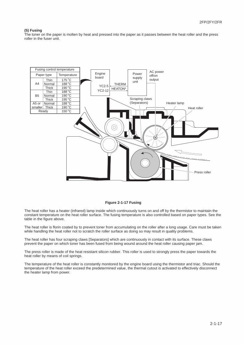
2FP/2FY/2FR
2-1-17
(5) FusingThe toner on the paper is molten by heat and pressed into the paper as it passes between the heat roller and the pressroller in the fuser unit.
Figure 2-1-17 Fusing
The heat roller has a heater (infrared) lamp inside which continuously turns on and off by the thermistor to maintain theconstant temperature on the heat roller surface. The fusing temperature is also controlled based on paper types. See thetable in the figure above.
The heat roller is florin coated by to prevent toner from accumulating on the roller after a long usage. Care must be takenwhile handling the heat roller not to scratch the roller surface as doing so may result in quality problems.
The heat roller has four scraping claws [Separators] which are continuously in contact with its surface. These clawsprevent the paper on which toner has been fused from being wound around the heat roller causing paper jam.
The press roller is made of the heat resistant silicon rubber. This roller is used to strongly press the paper towards theheat roller by means of coil springs.
The temperature of the heat roller is constantly monitored by the engine board using the thermistor and triac. Should thetemperature of the heat roller exceed the predetermined value, the thermal cutout is activated to effectively disconnectthe heater lamp from power.
Heat rollerHeater lamp
HEATON*
AC power off/on output
THERM
Engine board
YC2-12YC2-5
Power supply unitThin
NormalThickThin
NormalThick
NormalThick
A4
B5
Ready
A5 or smaller
Paper typeFusing control temperature
Temperature
Press roller
Scraping claws(Separators)
175 C188 C190 C188 C190 C195 C188 C190 C150 C
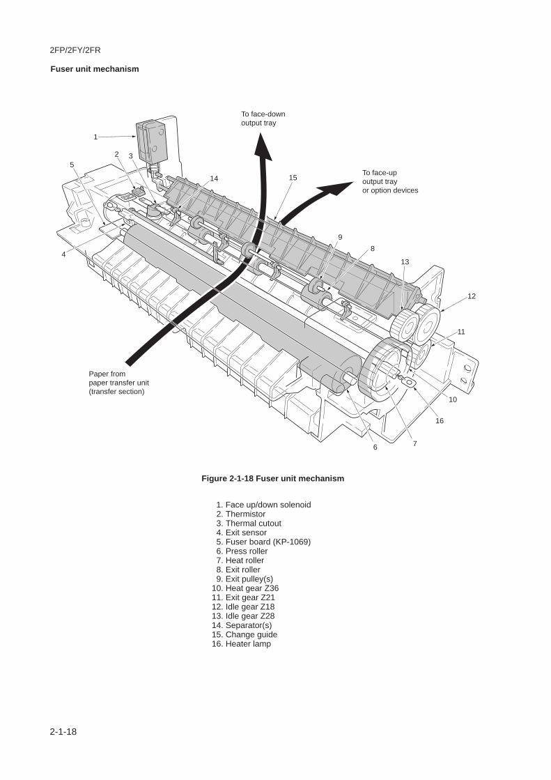
2FP/2FY/2FR
2-1-18
Fuser unit mechanism
To face-up output trayor option devices
To face-down output tray
1
4
5
6
11
12
13
98
1514
2 3
Paper from paper transfer unit(transfer section)
10
16
7
1. Face up/down solenoid 2. Thermistor 3. Thermal cutout 4. Exit sensor 5. Fuser board (KP-1069) 6. Press roller 7. Heat roller 8. Exit roller 9. Exit pulley(s)10. Heat gear Z3611. Exit gear Z2112. Idle gear Z1813. Idle gear Z2814. Separator(s)15. Change guide16. Heater lamp
Figure 2-1-18 Fuser unit mechanism
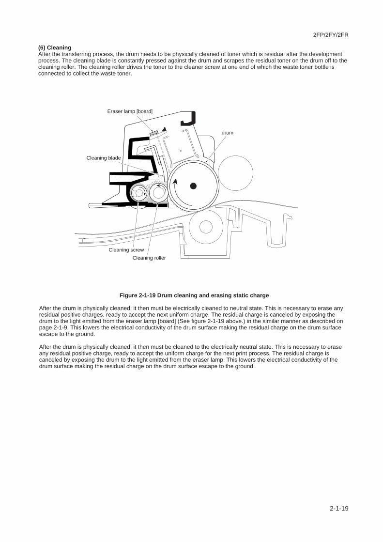
2FP/2FY/2FR
2-1-19
(6) CleaningAfter the transferring process, the drum needs to be physically cleaned of toner which is residual after the developmentprocess. The cleaning blade is constantly pressed against the drum and scrapes the residual toner on the drum off to thecleaning roller. The cleaning roller drives the toner to the cleaner screw at one end of which the waste toner bottle isconnected to collect the waste toner.
Figure 2-1-19 Drum cleaning and erasing static charge
After the drum is physically cleaned, it then must be electrically cleaned to neutral state. This is necessary to erase anyresidual positive charges, ready to accept the next uniform charge. The residual charge is canceled by exposing thedrum to the light emitted from the eraser lamp [board] (See figure 2-1-19 above.) in the similar manner as described onpage 2-1-9. This lowers the electrical conductivity of the drum surface making the residual charge on the drum surfaceescape to the ground.
After the drum is physically cleaned, it then must be cleaned to the electrically neutral state. This is necessary to eraseany residual positive charge, ready to accept the uniform charge for the next print process. The residual charge iscanceled by exposing the drum to the light emitted from the eraser lamp. This lowers the electrical conductivity of thedrum surface making the residual charge on the drum surface escape to the ground.
Eraser lamp [board]
drum
Cleaning blade
Cleaning screwCleaning roller

2FP/2FY/2FR
2-1-20
This page is intentionally left blank.
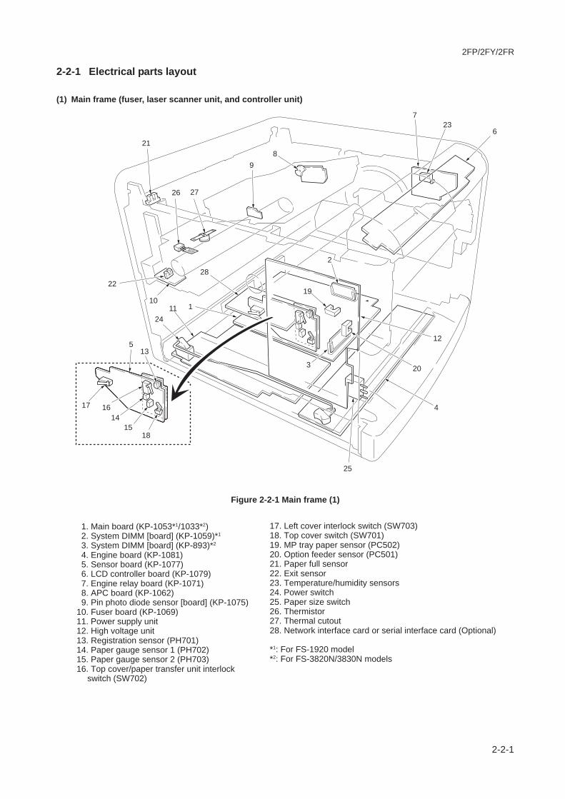
2FP/2FY/2FR
2-2-1
2-2-1 Electrical parts layout
(1) Main frame (fuser, laser scanner unit, and controller unit)
Figure 2-2-1 Main frame (1)
1. Main board (KP-1053*1/1033*2) 2. System DIMM [board] (KP-1059)*1
3. System DIMM [board] (KP-893)*2
4. Engine board (KP-1081) 5. Sensor board (KP-1077) 6. LCD controller board (KP-1079) 7. Engine relay board (KP-1071) 8. APC board (KP-1062) 9. Pin photo diode sensor [board] (KP-1075)10. Fuser board (KP-1069)11. Power supply unit12. High voltage unit13. Registration sensor (PH701)14. Paper gauge sensor 1 (PH702)15. Paper gauge sensor 2 (PH703)16. Top cover/paper transfer unit interlock
switch (SW702)
17. Left cover interlock switch (SW703)18. Top cover switch (SW701)19. MP tray paper sensor (PC502)20. Option feeder sensor (PC501)21. Paper full sensor22. Exit sensor23. Temperature/humidity sensors24. Power switch25. Paper size switch26. Thermistor27. Thermal cutout28. Network interface card or serial interface card (Optional)
*1: For FS-1920 model*2: For FS-3820N/3830N models
19
11 1
2
5
22
6
89
27
7
26
20
25
21
16
15
12
13
1417 4
28
18
3
10
23
24

2FP/2FY/2FR
2-2-2
Figure 2-2-2 Main frame (2)
1. Main motor 2. Polygon motor 3. Cooling fan motor 4. Controller unit fan motor 5. Developer fan motor 6. CPU cooling fan motor*1
7. Face up/down solenoid 8. MP feed solenoid 9. Middle feed clutch10. Feed clutch11. Registration clutch12. Heater lamp13. AC inlet
*1: For FS-3820N/3830N models only
6
5
89
10
11
2
7
412
13
3
1

2FP/2FY/2FR
2-2-3
Figure 2-2-3 Drum and developer
1. Drum board (KP-1064) 2. Waste toner full sensor [board] (KP-1065) 3. Waste toner full sensor (receiver) 4. Eraser lamp [board] (KP-1067) 5. Zener board (KP-1073) 6. Toner sensor 7. Toner motor
7
6
3
4
2
1
Drum unit
Developer
5
(2) Drum and developer

2FP/2FY/2FR
2-2-4
This page is intentionally left blank.

2FP/2FY/2FR
2-3-1
2-3-1 Main board
For FS-1920 model (KP-1053)
Figure 2-3-1 Main board (KP-1053) circuit block diagram
Digital Transistor
74LV32A
YC6
USB I/FUSBDN
CDD15-8 EDB15-8
EB
IU D
ata
bus
EBIU Address bus
VBUS
USBDPUSBINIT
EBA22, EBA10-1
EBA22, EBA10-1
CDRST1
CDET21, CDRST2
CDWAITNRESETN CDWAITN
EXTOR11,12CDCSN2
CDWAITN
EBOEN1, EBWEN1
CDET CDCSN1EXTIOR1 CDET1,2
YC8
RESETN
FPCLKFPDIRFPDAT
VDEONSPLPDNVDATAP, VDATAN
EGSI, SCKN
SCK, SO, SEL[0-2]SLREADYOP24V, OP5V
EGSO, SBSY, SDIR, EGIRN
X2
X’tal (System)
X’tal (USB)
X’tal (Video)
25.0000 MHz
48.0000 MHz
X3
X1
YC4
YC7
Parallel I/F
30.2394 MHz
Engine I/F
Option I/F
CXIN
VXINVXOUT
U2
U16
48MHZIN
PNSELINPNSTROBE, PNAUTOFD,PNINITPNACK, PBUSY, PPERRORPSELECT, PFAULT
PPDATA7-0
YC5
PDATA7-0
NSELINPDATA7-0
Option serial I/FP1284DIR
DTR, RTS, TXDCTS, DSR, RXDRSSEL
YC9DBTXDDBRXD, DBCLK
[Debugger connector]
YC10TDO
TDI, TCK, TMS, HALTN
RISC watch connector
U13
3.3 V Regulator+5 V1 +3.3 V1
SDRAM Data bus SDD31-0
SDD15-0
SDD31-16
SDCSN1-2
SDA12-0
SDCLK
SDCLK
SDD31-0
SDA12-0
SDA12-0SDRAM Address bus YS02
OptionSDRAMDIMM�Slot
U11
IIC EEPROM
IICSCLIICSDA
SDA12-0
SDCSN0
DQMLM, DQMLLDQMUU, DQMUM
RASN, CASN, WEN, BA1, BA0, SDCLKE
OPRSTNOPRDY, DMAACKN, IORN,IOWN, EBCSN4DMAREQ, OPACKN, OPIRN
EBA15-1
YC1
Option I/FKUIO-LV (3.3 V)
EBD31-16
EBD31-0
U4
API ROMSocket
EBD31-16
EBD31-16
EBD31-16
U3
EBA21-1
EBA21-1
EBCSN1, EBOEN2
EBCSN0, EBOEN2
EBA21-1
EBA21-20
EBCSN0, EBCSN1, EBOEN0, EBWEN0
YS1System DIMMSlot 1
(Code ROM)
SDRAM
U09
SDRAM
U10
YC2
OptionMemory
cardsocket
EDB15-0
YC3
U4
OptionHarddisk
socket
CPUU01
CDD7-0 EDB7-0U5
PowerPC 266 MHz(Core ASIC)
U1
U12
Font Mask ROM
74LV00
Q1
U8
U7
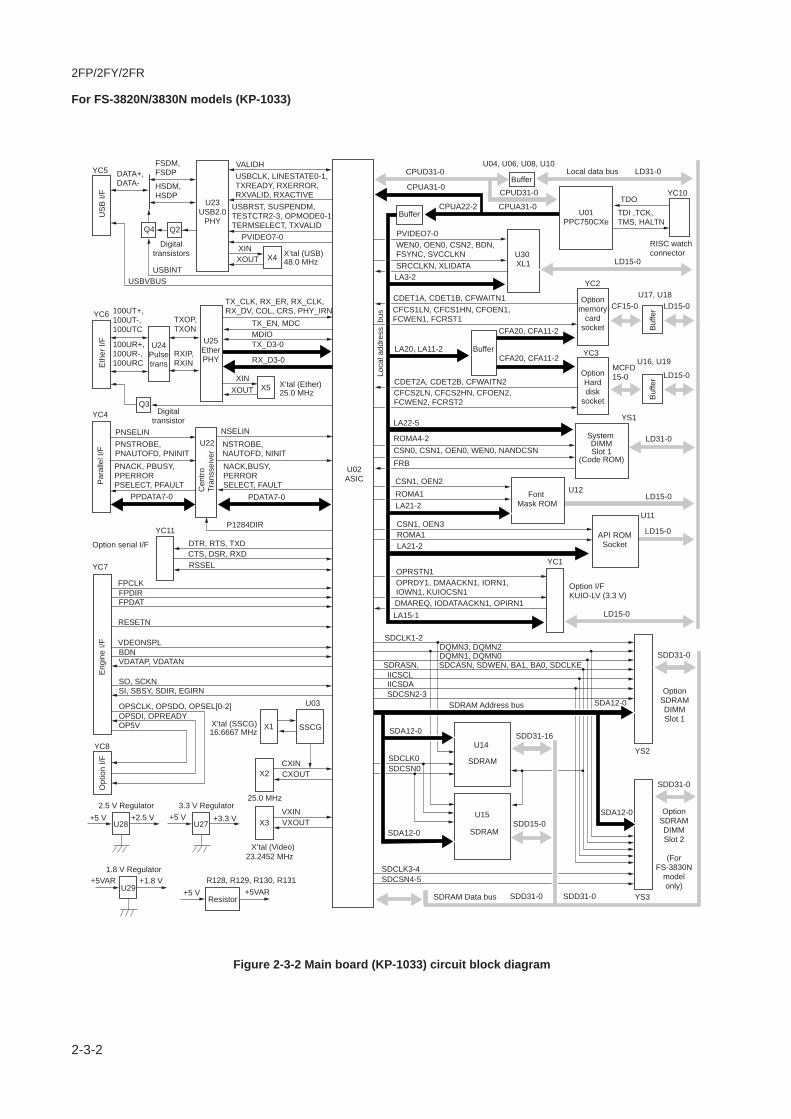
2FP/2FY/2FR
2-3-2
For FS-3820N/3830N models (KP-1033)
Figure 2-3-2 Main board (KP-1033) circuit block diagram
XOUT
LA20, LA11-2
LA3-2
CFA20, CFA11-2
CFCS2LN, CFCS2HN, CFOEN2, FCWEN2, FCRST2
CDET2A, CDET2B, CFWAITN2
CFCS1LN, CFCS1HN, CFOEN1, FCWEN1, FCRST1
CDET1A, CDET1B, CFWAITN1
SRCCLKN, XLIDATA
PVIDEO7-0
CPUD31-0
CPUD31-0
CPUA31-0CPUA22-2
CPUA31-0
WEN0, OEN0, CSN2, BDN,FSYNC, SVCCLKN
YC8
RESETN
FPCLKFPDIRFPDAT
VDEONSPLBDNVDATAP, VDATAN
SO, SCKN
OPSCLK, OPSDO, OPSEL[0-2]OPSDI, OPREADYOP5V
SI, SBSY, SDIR, EGIRN
X’tal (Video)
X’tal (SSCG)
X3
YC4
YC5
YC7
Par
alle
l I/F
Cen
troTr
anss
eive
r
23.2452 MHz
Eng
ine
I/FO
ptio
n I/F
VXINVXOUT
X2
25.0 MHz
CXINCXOUT
X116.6667 MHz
PNSELIN
VALIDHFSDM,FSDPDATA+,
DATA-
100UT+,100UT-,100UTC
TXOP,TXON
RXIP,RXIN
100UR+,100UR-,100URC
HSDM,HSDP
USBCLK, LINESTATE0-1,TXREADY, RXERROR,RXVALID, RXACTIVE
USBRST, SUSPENDM,TESTCTR2-3, OPMODE0-1TERMSELECT, TXVALID
TX_CLK, RX_ER, RX_CLK,RX_DV, COL, CRS, PHY_IRN
PNSTROBE, PNAUTOFD, PNINIT
NSTROBE, NAUTOFD, NINIT
PNACK, PBUSY, PPERRORPSELECT, PFAULT
NACK,BUSY, PERRORSELECT, FAULT
PPDATA7-0
PVIDEO7-0
USBVBUSUSBINT
YC11
PDATA7-0
NSELIN
Option serial I/F
US
B I/
F
YC6
Eth
er I/
F
P1284DIR
DTR, RTS, TXDCTS, DSR, RXDRSSEL
RISC watch connector
U27
3.3 V Regulator+5 V +3.3 V
U28
U03
2.5 V Regulator+5 V +2.5 V
U29
1.8 V RegulatorR128, R129, R130, R131+5VAR +1.8 V
Resistor+5 V +5VAR SDRAM Data bus SDD31-0 SDD31-0
SDD31-0
SDD15-0
SDD31-16
SDA12-0
SDCLK3-4SDCSN4-5
SDA12-0
SDA12-0SDRAM Address bus
YS2
YS3
OptionSDRAMDIMMSlot 2
(ForFS-3830N
modelonly)
SDD31-0
OptionSDRAMDIMMSlot 1
SDCLK1-2
SDA12-0
SDCLK0SDCSN0
IICSCLIICSDASDCSN2-3
SDRASN, SDCASN, SDWEN, BA1, BA0, SDCLKE
DQMN3, DQMN2DQMN1, DQMN0
OPRSTN1OPRDY1, DMAACKN1, IORN1,IOWN1, KUIOCSN1DMAREQ, IODATAACKN1, OPIRN1LA15-1
YC1
Option I/FKUIO-LV (3.3 V)
LD15-0
LD15-0
LD15-0
U11
API ROMSocket
LD31-0
U12
LA21-2ROMA1CSN1, OEN3
LA21-2ROMA1CSN1, OEN2
LA22-5
CSN0, CSN1, OEN0, WEN0, NANDCSNROMA4-2
FRB
YS1
System DIMMSlot 1
(Code ROM)
SDRAM
U14
SDRAM
U15
YC3
OptionHarddisk
socket
MCFD15-0 LD15-0
U17, U18
U04, U06, U08, U10
U16, U19
U22
U23USB2.0
PHY
U25EtherPHY
U24Pulsetrans
Q4
Q3
Q2
Font Mask ROM
CFA20, CFA11-2
Buffer
Buf
fer
YC2
Optionmemory
cardsocket
YC10
U30 XL1
CF15-0 LD15-0
LD15-0
TDI ,TCK, TMS, HALTN
TDO
LD31-0Local data bus
Loca
l add
ress
bus
Buf
fer
Buffer
Buffer
U01PPC750CXe
SSCG
X4XINXOUT
X’tal (USB)48.0 MHz
X5XIN
TX_EN, MDCMDIOTX_D3-0
RX_D3-0
X’tal (Ether)25.0 MHz
Digitaltransistors
Digitaltransistor
U02ASIC

2FP/2FY/2FR
2-3-3
2-3-2 Engine board
Figure 2-3-3 Engine board circuit block diagram
Address/Data multiplex bus AD0 - AD7
Address bus A17 - A18
Address bus LA0 - LA7
5 V DCpower saver/CPU coolingfan motor drive circuit
24 V DCpower
saver circuit
Waste tonerfull detection
circuit
Paper gaugesensing circuit
Powersupply
unit
Sensorboard
Laserscanner
unit
CPUcooling
fanmotor*
Highvoltage
unit
Enginerelayboard
Optionunit
Cont-roller
unit fanmotor
Bus buffer(U11)
ZCROSS
5VSAVE*
+24V2 +24V3
+5V3+24V1
THERM
+5V1, +24V1
+24V1
+24V3
HTEMP*
HEATON
THDEAD*
TONSCANTNEMP*
MCHON, TRCHON, RTRCHON*,TRVSEL1,TRVSEL2, TRVSEL3,
HVCLK1
MMOTON, MPFSOL, FEDDR, MIDDR, REGDR
TMOTON
DLPTYPE, CONTYPE
TNMOC
HUNIT*, HANDS*
FPCLK, FPDIRFPDATA
+3.3V1
SIOUTVSEREQ*
SOOUT, SCLKOUT
RD*, WR*, ALE
OPSCLK,OPSDO
BFANON
OPTSDI
OPSEL3-5
OPSDI, OPRDY*
SYSRES*, SDIR, VDFON1*, PDOUT*, 20PTRIG, SBSY*EGIR, VDFON1* SCLKIN, SOIN
OPSEL0-2
FRCS*
GAINTSYSCLK
RESET*
RESET*
RESET*
HEATON*
AIRTEMP, AIRWET
WETCK1, WETCK2
FDPFUL*, EXITPAP*
FDON, FUONFDDR, FUDR
FANDR, DVFANDR
FPRST*
DVFAN, FANON*DVFANSPD, FANSPD
Driver
Driver
Engine board
ERASEERDEAD*
POLCLK, POLON, POLRDY*
SAMPLE1*, POWCONTPDIN*
WTNLED
EECLKEEDIO
CASIZE
WTONFUL*
REGPAP, TCOVOP, SCOVOP*,FCOVOP*,
PAPVOL
OPRDY*ECOPOWER
A8 - A18
Toner motorcontrolcircuit
Coolingfan motor
driver circuit
Controllerunit
fan motordriver circuit
Bus buffer
(UU12)
Mainboard
MMOTRDY*
LASER*
Eraser lampcontrolcircuit
FlashROM(U2)CPU
(U1)
Enginegate array(U7)
ResetIC
(U5)
Abnormaltemperature
detectioncircuit
3-terminalregulator
(U13)
Thermisorblown-outdetection
Heater lampcontrol circuit
*: For FS-3820N/3830Nmodelsonly

2FP/2FY/2FR
2-3-4
Connector Pin No. Signal I/O Voltage Description1 +24V3 O 24 V DC 24 V DC power supply2 FDPFUL* I 0/5 V DC Paper full sensor: On/Off3 FUDR O 0/24 V DC Face- up/down solenoid (UP): On/Off4 FDDR O 0/24 V DC Face- up/down solenoid (DOWN): On/Off5 THERM I Analog Thermistor detection voltage6 EXITPAP* I 0/5 V DC Exit sensor: On/Off7 +5V1 I 5 V DC 5 V DC power supply8 GND - Ground Ground9 +24V3 O 24 V DC 24 V DC power supply
10 SLEEP - - Not used11 ZCROSS I 0/5 V DC (pulse) Zero cross signal12 HEATON* O 0/24 V DC Heater lamp: On/Off13 +5V1 I 5 V DC 5 V DC power supply14 +5V1 I 5 V DC 5 V DC power supply15 +5V1 I 5 V DC 5 V DC power supply16 +5V1 I 5 V DC 5 V DC power supply17 GND - Ground Ground18 GND - Ground Ground19 GND - Ground Ground20 GND - Ground Ground21 +24V1 I 24 V DC 24 V DC power supply22 +24V1 I 24 V DC 24 V DC power supply23 +24V1 I 24 V DC 24 V DC power supply24 +24V1 I 24 V DC 24 V DC power supply
1 BFANDR(+5V) O 0/2.5/5 V DC Controller unit fan motor:Stop/Low speed/High speed
2 GND - Ground Ground
1 +24V1 O 24 V DC 24 V DC power supply2 +24V1 O 24 V DC 24 V DC power supply3 +24V1 O 24 V DC 24 V DC power supply4 GND - Ground Ground5 GND - Ground Ground6 +24V2 I 24 V DC 24 V DC power supply (via interlock switches)7 +24V2 I 24 V DC 24 V DC power supply (via interlock switches)8 +24V2 I 24 V DC 24 V DC power supply (via interlock switches)9 ERASEDR O 0/24 V DC Eraser lamp: On/Off
10 WTNLED* O 0/5 V DC (pulse) Waste toner full sensor (LED): On/Off11 TNRFUL* I 0/5 V DC (pulse) Waste toner full sensor: On/Off12 +5V1 O 5 V DC 5 V DC power supply13 +5V2 O 5 V DC 5 V DC power supply14 GND - Ground Ground15 EEDIO I/O 0/5 V DC (pulse) Serial data signal for EEPROM (drum board)16 EECLK O 0/5 V DC (pulse) Clock signal for EEPROM (drum board)17 REGPAP I 0/5 V DC Registration sensor: On/Off18 PVOLAN1 I 0/5 V DC Paper gauge sensor 1: On/Off19 TCOVOP I 0/5 V DC Top cover switch: On/Off20 FCOVOP* I 0/24 V DC Top cover/paper transfer unit interlock switch:
On/Off21 CASIZE I 0/ Paper size switch: Cassette not installed/
1.05 V/ [OTHER]/1.64 V/ [LG]/2.15 V/ [LTR]/2.38 V/ [A4]/2.70 V/ [A5]/2.91 V/ [B5]/3.12 V Cassette size error (Toner install mode reset)
22 PVOLAN2 I 0/5 V DC Paper gauge sensor 2: On/Off
YC2Connectedto thepowersupplyboard
YC3Connectedto thecontrollerunit fanmotor
YC4Connectedto thesensorboard

2FP/2FY/2FR-2
2-3-5
Connector Pin No. Signal I/O Voltage DescriptionYC5
Connectedto the highvoltage unit
YC6Connectedto theoptionalunit
1 TRVSEL1* O 0/24 V DC Transfer charger output voltage setting 12 TRVSEL2* O 0/24 V DC Transfer charger output voltage setting 23 +5V1 O 5 V DC 5 V DC power supply4 TRVSEL3* O 0/24 V DC Transfer charger output voltage setting 35 TNEMP* I 0/5 V DC Toner sensor: On (toner empty)/Off6 TRCHON* O 0/24 V DC Transfer charger: On/Off7 TONSCAN O 0/5 V DC (pulse) Scan signal for toner sensor8 HVCLK O 0/5 V DC (pulse) Clock signal for developing bias output9 GND - Ground Ground
10 MCHON* O 0/24 V DC Main charger: On/Off11 HUNIT* I 0/5 V DC Optional envelop feeder installation signal:
Installed/Not installed12 RTRCHON* O 0/24 V DC Transfer charger output reverse voltage: On/Off13 HANDS* I 0/5 V DC MP tray paper sensor: On/Off14 DLPTYPE I 0/5 V DC Developer identification signal:
Not installed/Developer DV-6315 +5V2 O 5 V DC 5 V DC power supply16 TMOTDR O 0/24 V DC Toner motor: On/Off17 CONTYPE I 0/5 V DC Toner container identification signal (for MICR):
Normal/Not installed (abnormal)18 +24V3 O 24 V DC 24 V DC power supply
1 OP24V O 24 V DC 24 V DC power supply2 GND - Ground Ground3 OP5V O 5 V DC 5 V DC power supply4 (PFSEL) - - Not used5 OPSCLK O 0/5 V DC (pulse) Clock signal for serial communication6 OPSEL0 O 0/5 V DC Optional unit identification code 07 OPSDI I 0/5 V DC (pulse) Serial communication data input signal8 OPSEL1 O 0/5 V DC Optional unit identification code 19 OPSDO O 0/5 V DC (pulse) Serial communication data output signal
10 OPSEL2 O 0/5 V DC Optional unit identification code 211 OPRDY* I 0/5 V DC Optional unit READY signal: Ready/Not ready12 GND - Ground Ground

2FP/2FY/2FR-2
2-3-6
Connector Pin No. Signal I/O Voltage Description
1 +24V3 O 24 V DC 24 V DC power supply2 +3.3V1 O 3.3 V DC 3.3 V DC power supply3 MPFSOL* O 0/24 V DC MP feed solenoid: On/Off4 FPDATA I/O 0/3.3V DC(pulse) LCD controller board data signal5 MIDDR* O 0/24 V DC Middle feed clutch: On/Off6 FPDIR I 0/3.3V DC LCD controller board control signal7 +24V3 O 24 V DC 24 V DC power supply8 FPCLK I 0/3.3V DC LCD controller board control signal9 GND - Ground Ground
10 GND - Ground Ground11 FEDDR* O 0/24 V DC Feed clutch: On/Off12 FPRST* O 0/3.3V DC LCD controller board RESET signal13 +24V3 O 24 V DC 24 V DC power supply14 FANDR O 0/12/24 V DC Cooling fan motor: High speed/Low speed/Stop15 REGDR* O 0/24 V DC Registration clutch: On/Off16 MMOTON* O 0/5 V DC Main motor: On/Off17 GND - Ground Ground18 MMOTRDY* I 0/5 V DC Main motor READY signal: Ready/Not ready19 +5V3 O 5 V DC 5 V DC power supply20 SAMPLE* O 0/5 V DC Sample & Hold signal (laser power output)21 DVFANDR O 12/24 V DC Developer fan motor: Low/High speed22 LASER* O 0/5 V DC Laser output: On/Off23 VD0+ O 0/3.3V DC(pulse) Laser output data signal (+)24 VD0- O 0/3.3V DC(pulse) Laser output data signal (-)25 GND - Ground Ground26 +5V3 O 5 V DC 5 V DC power supply27 PDIN* I 0/5V DC (pulse) Pin photo diode sensor detection signal28 GND - Ground Ground29 POLCLK* O 0/5V DC (pulse) Clock signal for polygon motor rotation speed30 POLRDY* I 0/5V DC Polygon motor READY signal: Ready/Not ready31 POLON* O 0/5V DC Polygon motor: On/Off32 GND - Ground Ground33 +24V3 O 24 V DC 24 V DC power supply34 GND - Ground Ground
YC7Connectedto theenginerelayboard, APCboard, andpolygonmotor
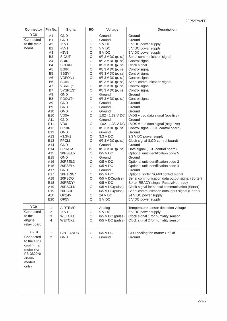
2FP/2FY/2FR
2-3-7
Connector Pin No. Signal I/O Voltage Description
A1 GND - Ground GroundB1 GND - Ground GroundA2 +5V1 O 5 V DC 5 V DC power supplyB2 +5V1 O 5 V DC 5 V DC power supplyA3 +5V1 O 5 V DC 5 V DC power supplyB3 SIOUT O 0/3.3 V DC (pulse) Serial communication signalA4 SDIR O 0/3.3 V DC (pulse) Control signalB4 SCLKN O 0/3.3 V DC (pulse) Clock signalA5 EGIR O 0/3.3 V DC (pulse) Control signalB5 SBSY* O 0/3.3 V DC (pulse) Control signalA6 VDFON1 O 0/3.3 V DC (pulse) Control signalB6 SOIN I 0/3.3 V DC (pulse) Serial communication signalA7 VSREQ* O 0/3.3 V DC (pulse) Control signalB7 SYSRES* O 0/3.3 V DC (pulse) Control signalA8 GND - Ground GroundB8 PDOUT* O 0/3.3 V DC (pulse) Control signalA9 GND - Ground GroundB9 GND - Ground Ground
A10 GND - Ground GroundB10 VD0+ O 1.02 - 1.38 V DC LVDS video data signal (positive)A11 GND - Ground GroundB11 VD0- O 1.02 - 1.38 V DC LVDS video data signal (negative)A12 FPDIR O 0/3.3 V DC (pulse) Control signal (LCD control board)B12 GND - Ground GroundA13 +3.3V1 O 3.3 V DC 3.3 V DC power supplyB13 FPCLK O 0/3.3 V DC (pulse) Clock signal (LCD control board)A14 GND - Ground GroundB14 FPDATA I/O 0/3.3 V DC (pulse) Data signal (LCD control board)A15 20PSEL5 O 0/5 V DC Optional unit identification code 5B15 GND - Ground GroundA16 20PSEL3 O 0/5 V DC Optional unit identification code 3B16 20PSEL4 O 0/5 V DC Optional unit identification code 4A17 GND - Ground GroundB17 20PTRIG* O 0/5 V DC Optional sorter SO-60 control signalA18 20PSDO O 0/5 V DC(pulse) Serial communication data output signal (Sorter)B18 20PRDY* I 0/5 V DC Sorter READY singal: Ready/Not readyA19 20PSCLK O 0/5 V DC(pulse) Clock signal for serical communication (Sorter)B19 20PSDI I 0/5 V DC(pulse) Serial communication data input signal (Sorter)A20 OP24V O 24 V DC 24 V DC power supplyB20 OP5V O 5 V DC 5 V DC power supply
1 AIRTEMP I Analog Temperature sensor detection voltage2 +5V1 O 5 V DC 5 V DC power supply3 WETCK1 O 0/5 V DC (pulse) Clock signal 1 for humidity sensor4 WETCK2 O 0/5 V DC (pulse) Clock signal 2 for humidity sensor
1 CPUFANDR O 0/5 V DC CPU cooling fan motor: On/Off2 GND - Ground Ground
YC8Connectedto the mainboard
YC9Connectedto theenginerelay board
YC10Connectedto the CPUcooling fanmotor (forFS-3820N/3830Nmodelsonly)

2FP/2FY/2FR
2-3-8
2-3-3 Power supply unit
The power supply unit provides the AC power input and DC power and outputs. The high voltage bias generator circuit ismounted on a separate board. A simplified schematic diagram is shown below.
Figure 2-3-4 Power supply unit circuit block diagram
FETSwitchingcontrolcircuit
Zero crosssignalgenerationcircuit
Powerswitch
Currentfuse
Noisefiltercircuit
Transformer
24 V DCrectifier/smoothingcircuit
Photo-coupler
Photo-coupler
Photo-Triac
Triac
ZCROSS
FDDREXITPAP*
FDFULTHERM
HEATON*
FUDR
+24V1
+24V3
+5V1
GND
GND
Heaterlamp
ACinput
Rectifiercircuit
5 V DCrectifier/smoothingcircuit
Power supply unit
Fuser board
Interlockswitches
Thermalcutout
Thermistor
Paper full sensor Exit sensor
Face up/down solenoid
+Overvoltage/currentdetectioncircuit
+5V1 +24V3
24 V DCregulatorcircuit
+24V
1
+24V
2E
CO
PO
WE
REngine board

2FP/2FY/2FR
2-3-9
Connector Pin No. Signal I/O Voltage DescriptionCN1
Connectedto the ACinlet
CN2Connectedto theheater lamp
YC901Connectedto theengineboard
YC902Connectedto the fuserboard
1 LIVE I 120 V AC AC power supply220 - 240 V AC
2 GND - - Ground3 NEUTRAL I 120 V AC AC power supply
220 - 240 V AC
1 LIVE O 120 V AC Power supply for heater lamp220 - 240 V AC
2 NEUTRAL O 120 V AC Power supply for heater lamp220 - 240 V AC
1 +24V3 I 24 V DC 24 V DC power supply2 FDPFUL* O 0/5 V DC Paper full sensor: On/Off3 FUDR I 0/24 V DC Face up/down solenoid (UP): On/Off4 FDDR I 0/24 V DC Face up/down solenoid (DOWN): On/Off5 THERM O Analog Thermistor detection voltage6 EXITPAP* O 0/5 V DC Exit sensor: On/Off7 +5V1 O 5 V DC 5 V DC power supply8 GND - Ground Ground9 +24V3 I 24 V DC 24 V DC power supply10 SLEEP - - Not used11 ZCROSS O 0/5 V DC (pulse) Zero cross signal12 HEATON* I 0/24 V DC Heater lamp: On/Off13 +5V1 O 5 V DC 5 V DC power supply14 +5V1 O 5 V DC 5 V DC power supply15 +5V1 O 5 V DC 5 V DC power supply16 +5V1 O 5 V DC 5 V DC power supply17 GND - Ground Ground18 GND - Ground Ground19 GND - Ground Ground20 GND - Ground Ground21 +24V1 O 24 V DC 24 V DC power supply22 +24V1 O 24 V DC 24 V DC power supply23 +24V1 O 24 V DC 24 V DC power supply24 +24V1 O 24 V DC 24 V DC power supply
1 +5V1 O 5 V DC 5 V DC power supply2 GND - Ground Ground3 THERM I Analog Thermistor detection voltage4 EXITPAP* I 0/5 V DC Exit sensor: On/Off5 FDDR O 0/24 V DC Face up/down solenoid (DOWN): On/Off6 FUDR O 0/24 V DC Face up/down solenoid (UP): On/Off7 +24V3 O 24 V DC 24 V DC power supply8 FDPFUL* I 0/5 V DC Paper full sensor: On/Off

2FP/2FY/2FR
2-3-10
This page is intentionally left blank.
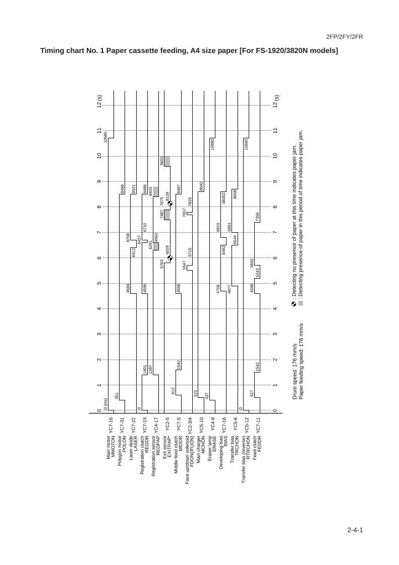
2FP/2FY/2FR
2-4-1
Timing chart No. 1 Paper cassette feeding, A4 size paper [For FS-1920/3820N models]
(s)
(s)
0 (m
s)10
680
Mai
n m
otor
MM
OTO
NY
C7-
16
YC
7-31
YC
7-22
YC
7-15
YC
4-17
YC
2-5
YC
7-5
YC
2-3/
4
YC
5-10
YC
4-9
YC
7-16
YC
5-6
YC
5-12
YC
7-11
351
Pol
ygon
mot
orP
OLO
N84
8645
9467
08La
ser d
iode
LAS
ER
6412
8521
064
57R
egis
tratio
n cl
utch
RE
GD
R14
0145
9667
1084
8613
9762
9184
03R
egis
tratio
n se
nsor
RE
GP
AP
6562
5763
7487
7876
9602
Exi
t sen
sor
EX
ITP
AP
*60
2981
3961
2M
iddl
e fe
ed c
lutc
hM
IDD
R15
4245
9684
8755
4776
57Fa
ce u
p/do
wn
sole
noid
FDO
N(/F
UO
N)
5715
7825
522
Mai
n ch
arge
rM
CH
ON
8642
437
Era
ser l
amp
ER
AS
E10
680
4706
6819
Dev
elop
ing
bias
BIA
S64
9286
002
4877
6991
Tran
sfer
bia
sTR
CH
ON
6544
8658
0Tr
ansf
er b
ias
(rev
erse
)R
TRC
HO
N10
680
527
4598
5692
Feed
clu
tch
FED
DR
1542
5243
7356
12
34
06
78
95
1112
10
12
34
06
78
95
1112
10
Dru
m s
peed
: 176
mm
/sP
aper
feed
ing
spee
d: 1
76 m
m/s
: D
etec
ting
no p
rese
nce
of p
aper
at t
his
time
indi
cate
s pa
per j
am.
: Det
ectin
g pr
esen
ce o
f pap
er in
this
per
iod
of ti
me
indi
cate
s pa
per j
am.
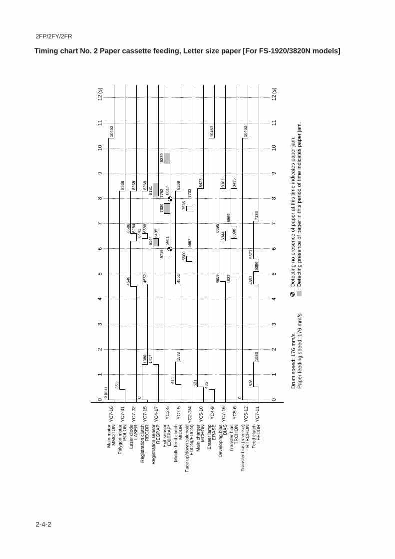
2FP/2FY/2FR
2-4-2
Timing chart No. 2 Paper cassette feeding, Letter size paper [For FS-1920/3820N models]
(s)
(s)
0 (m
s)10
463
351
8268
4549
6586
6264
8268
064
4113
8845
5265
8882
6814
1761
4481
8164
3957
1573
3977
5293
7959
8180
1761
115
3345
5182
6855
0075
3556
6777
0352
184
2343
610
463
4659
6695
6344
8383
4832
6869
6398
8435
010
463
526
4553
5573
1533
5096
7133
12
34
56
78
910
1112
01
23
45
67
89
1011
12
0
Dru
m s
peed
: 176
mm
/sP
aper
feed
ing
spee
d: 1
76 m
m/s
: D
etec
ting
no p
rese
nce
of p
aper
at t
his
time
indi
cate
s pa
per j
am.
: Det
ectin
g pr
esen
ce o
f pap
er in
this
per
iod
of ti
me
indi
cate
s pa
per j
am.
Mai
n m
otor
MM
OTO
NY
C7-
16
YC
7-31
YC
7-22
YC
7-15
YC
4-17
YC
2-5
YC
7-5
YC
2-3/
4
YC
5-10
YC
4-9
YC
7-16
YC
5-6
YC
5-12
YC
7-11
Pol
ygon
mot
orP
OLO
NLa
ser d
iode
LAS
ER
Reg
istra
tion
clut
chR
EG
DR
Reg
istra
tion
sens
orR
EG
PA
PE
xit s
enso
rE
XIT
PA
P*
Mid
dle
feed
clu
tch
MID
DR
Face
up/
dow
n so
leno
idFD
ON
(/FU
ON
)M
ain
char
ger
MC
HO
NE
rase
r lam
pE
RA
SE
Dev
elop
ing
bias
BIA
STr
ansf
er b
ias
TRC
HO
NTr
ansf
er b
ias
(rev
erse
)R
TRC
HO
NFe
ed c
lutc
hFE
DD
R
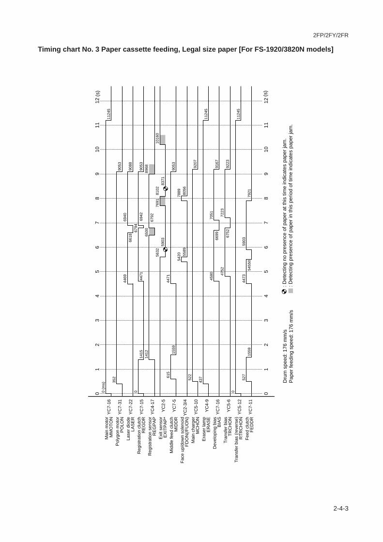
2FP/2FY/2FR
2-4-3
Timing chart No. 3 Paper cassette feeding, Legal size paper [For FS-1920/3820N models]
0 (m
s)11
245
352
9053
4469
6940
6618
9088
067
9414
1544
7169
4290
5314
1265
0089
6867
9256
3276
9181
0210
160
5903
8371
615
4471
1559
9053
5420
7889
5589
8056
522
9207
437
1124
545
8070
5166
9991
6747
5272
2367
5292
230
1124
552
744
7359
0315
5954
550
7921
(s)
(s)
12
34
06
78
95
1112
10
12
34
06
78
95
1112
10
Dru
m s
peed
: 176
mm
/sP
aper
feed
ing
spee
d: 1
76 m
m/s
: D
etec
ting
no p
rese
nce
of p
aper
at t
his
time
indi
cate
s pa
per j
am.
: Det
ectin
g pr
esen
ce o
f pap
er in
this
per
iod
of ti
me
indi
cate
s pa
per j
am.
Mai
n m
otor
MM
OTO
NY
C7-
16
YC
7-31
YC
7-22
YC
7-15
YC
4-17
YC
2-5
YC
7-5
YC
2-3/
4
YC
5-10
YC
4-9
YC
7-16
YC
5-6
YC
5-12
YC
7-11
Pol
ygon
mot
orP
OLO
NLa
ser d
iode
LAS
ER
Reg
istra
tion
clut
chR
EG
DR
Reg
istra
tion
sens
orR
EG
PA
PE
xit s
enso
rE
XIT
PA
P*
Mid
dle
feed
clu
tch
MID
DR
Face
up/
dow
n so
leno
idFD
ON
(/FU
ON
)M
ain
char
ger
MC
HO
NE
rase
r lam
pE
RA
SE
Dev
elop
ing
bias
BIA
STr
ansf
er b
ias
TRC
HO
NTr
ansf
er b
ias
(rev
erse
)R
TRC
HO
NFe
ed c
lutc
hFE
DD
R

2FP/2FY/2FR
2-4-4
Timing chart No. 4 MP tray feeding, A4 size paper [For FS-1920/3820N models]
0 (m
s)11
227
352
9031
4464
6918
6611
9066
044
6667
9569
2112
5990
3112
5667
9189
4664
9656
2976
8580
8310
137
5899
8350
614
4466
1381
9031
5417
7868
5585
8035
523
9186
437
1122
745
7570
2966
9191
4648
5168
8064
1784
460
1122
752
860
6761
661
53
(s)
(s)
12
34
06
78
95
1112
10
12
34
06
78
95
1112
10
Dru
m s
peed
: 176
mm
/sP
aper
feed
ing
spee
d: 1
76 m
m/s
: D
etec
ting
no p
rese
nce
of p
aper
at t
his
time
indi
cate
s pa
per j
am.
: Det
ectin
g pr
esen
ce o
f pap
er in
this
per
iod
of ti
me
indi
cate
s pa
per j
am.
Mai
n m
otor
MM
OTO
NY
C7-
16
YC
7-31
YC
7-22
YC
7-15
YC
4-17
YC
2-5
YC
7-5
YC
2-3/
4
YC
5-10
YC
4-9
YC
7-16
YC
5-6
YC
5-12
Pol
ygon
mot
orP
OLO
NLa
ser d
iode
LAS
ER
Reg
istra
tion
clut
chR
EG
DR
Reg
istra
tion
sens
orR
EG
PA
PE
xit s
enso
rE
XIT
PA
P*
Mid
dle
feed
clu
tch
MID
DR
Face
up/
dow
n so
leno
idFD
ON
(/FU
ON
)M
ain
char
ger
MC
HO
NE
rase
r lam
pE
RA
SE
Dev
elop
ing
bias
BIA
STr
ansf
er b
ias
TRC
HO
NTr
ansf
er b
ias
(rev
erse
)R
TRC
HO
N
YC
7-3
MP
feed
sol
enoi
dM
PFS
OL

2FP/2FY/2FR
2-4-5
Timing chart No. 5 MP tray feeding, Letter size paper [For FS-1920/3820N models]
0 (m
s)10
471
351
8276
4568
6597
6284
8213
064
7212
6145
7166
0082
7612
5761
5781
8964
7057
3173
6077
5893
8860
0180
2861
245
7013
8582
7755
1875
4656
8777
1452
184
3243
610
471
4679
6707
6364
8392
4851
6880
6417
8446
010
471
526
5736
614
5824
(s)
(s)
12
34
06
78
95
1112
10
12
34
06
78
95
1112
10
Dru
m s
peed
: 176
mm
/sP
aper
feed
ing
spee
d: 1
76 m
m/s
: D
etec
ting
no p
rese
nce
of p
aper
at t
his
time
indi
cate
s pa
per j
am.
: Det
ectin
g pr
esen
ce o
f pap
er in
this
per
iod
of ti
me
indi
cate
s pa
per j
am.
Mai
n m
otor
MM
OTO
NY
C7-
16
YC
7-31
YC
7-22
YC
7-15
YC
4-17
YC
2-5
YC
7-5
YC
2-3/
4
YC
5-10
YC
4-9
YC
7-16
YC
5-6
YC
5-12
Pol
ygon
mot
orP
OLO
NLa
ser d
iode
LAS
ER
Reg
istra
tion
clut
chR
EG
DR
Reg
istra
tion
sens
orR
EG
PA
PE
xit s
enso
rE
XIT
PA
P*
Mid
dle
feed
clu
tch
MID
DR
Face
up/
dow
n so
leno
idFD
ON
(/FU
ON
)M
ain
char
ger
MC
HO
NE
rase
r lam
pE
RA
SE
Dev
elop
ing
bias
BIA
STr
ansf
er b
ias
TRC
HO
NTr
ansf
er b
ias
(rev
erse
)R
TRC
HO
N
YC
7-3
MP
feed
sol
enoi
dM
PFS
OL

2FP/2FY/2FR
2-4-6
Timing chart No. 6 MP tray feeding, Legal size paper [For FS-1920/3820N models]
0 (m
s)10
588
352
8395
4481
6619
6293
8429
064
9312
6244
8366
2183
9512
5961
7383
1364
9156
4773
7177
8595
1259
1880
5261
313
8544
8383
9554
3475
7056
0277
3852
285
5043
610
588
4593
6731
6373
8510
4764
6902
6431
8568
010
588
527
5756
616
5845
(s)
(s)
12
34
06
78
95
1112
10
12
34
06
78
95
1112
10
Dru
m s
peed
: 176
mm
/sP
aper
feed
ing
spee
d: 1
76 m
m/s
: D
etec
ting
no p
rese
nce
of p
aper
at t
his
time
indi
cate
s pa
per j
am.
: Det
ectin
g pr
esen
ce o
f pap
er in
this
per
iod
of ti
me
indi
cate
s pa
per j
am.
Mai
n m
otor
MM
OTO
NY
C7-
16
YC
7-31
YC
7-22
YC
7-15
YC
4-17
YC
2-5
YC
7-5
YC
2-3/
4
YC
5-10
YC
4-9
YC
7-16
YC
5-6
YC
5-12
Pol
ygon
mot
orP
OLO
NLa
ser d
iode
LAS
ER
Reg
istra
tion
clut
chR
EG
DR
Reg
istra
tion
sens
orR
EG
PA
PE
xit s
enso
rE
XIT
PA
P*
Mid
dle
feed
clu
tch
MID
DR
Face
up/
dow
n so
leno
idFD
ON
(/FU
ON
)M
ain
char
ger
MC
HO
NE
rase
r lam
pE
RA
SE
Dev
elop
ing
bias
BIA
STr
ansf
er b
ias
TRC
HO
NTr
ansf
er b
ias
(rev
erse
)R
TRC
HO
N
YC
7-3
MP
feed
sol
enoi
dM
PFS
OL

2FP/2FY/2FR
2-4-7
Timing chart No. 7 Optional paper feeder feeding, A4 size paper [For FS-1920/3820N models]
0 (m
s)10
540
351
8346
4429
6567
6240
8381
044
3164
4218
0665
7183
4618
0564
4061
2382
6256
0173
2577
3694
6158
6480
0169
744
5319
3083
4653
8275
1955
4976
8752
085
0143
610
540
4542
6678
6321
8461
4712
6851
6379
8518
010
540
1246
2541
750
3363
4434
4614
6511
1875
4678
6573
1054
0
(s)
(s)
12
34
06
78
95
1112
10
12
34
06
78
95
1112
10
Feed
clu
tch*
Feed
mot
or*
Dru
m s
peed
: 176
mm
/sP
aper
feed
ing
spee
d: 1
76 m
m/s
: D
etec
ting
no p
rese
nce
of p
aper
at t
his
time
indi
cate
s pa
per j
am.
: Det
ectin
g pr
esen
ce o
f pap
er in
this
per
iod
of ti
me
indi
cate
s pa
per j
am.
Mai
n m
otor
MM
OTO
NY
C7-
16
YC
7-31
YC
7-22
YC
7-15
YC
4-17
YC
2-5
YC
7-5
YC
2-3/
4
YC
5-10
YC
4-9
YC
7-16
YC
5-6
YC
5-12
Pol
ygon
mot
orP
OLO
NLa
ser d
iode
LAS
ER
Reg
istra
tion
clut
chR
EG
DR
Reg
istra
tion
sens
orR
EG
PA
PE
xit s
enso
rE
XIT
PA
P*
Mid
dle
feed
clu
tch
MID
DR
Face
up/
dow
n so
leno
idFD
ON
(/FU
ON
)M
ain
char
ger
MC
HO
NE
rase
r lam
pE
RA
SE
Dev
elop
ing
bias
BIA
STr
ansf
er b
ias
TRC
HO
NTr
ansf
er b
ias
(rev
erse
)R
TRC
HO
N
*: O
ptio
nal
pape
r fee
der P
F-60

2FP/2FY/2FR
2-4-8
Timing chart No. 8 Paper cassette feeding, A4 size paper [For FS-3830N model]
(s)
(s)
0 (m
s)12
109
Mai
n m
otor
MM
OTO
NY
C7-
16
YC
7-31
YC
7-22
YC
7-15
YC
4-17
YC
2-5
YC
7-5
YC
2-3/
4
YC
5-10
YC
4-9
YC
7-16
YC
5-6
YC
5-12
YC
7-11
352
Pol
ygon
mot
orP
OLO
N10
269
6953
87
72La
ser d
iode
LAS
ER
8478
1029
90
8667
Reg
istra
tion
clut
chR
EG
DR
1614
4956
8774
1026
9
1661
8365
1017
9R
egis
tratio
n se
nsor
RE
GP
AP
8665
7923
9369
9740
1118
6E
xit s
enso
rE
XIT
PA
P*
8153
9972
930
Mid
dle
feed
clu
tch
MID
DR
1734
6955
1026
9
7749
9567
Face
up/
dow
n so
leno
idFD
ON
(/FU
ON
)
7890
9708
494
Mai
n ch
arge
rM
CH
ON
1040
0
424
Era
ser l
amp
ER
AS
E12
109
1210
9
7045
8866
Dev
elop
ing
bias
BIA
S85
4410
365
7190
9009
Tran
sfer
bia
sTR
CH
ON
8573
1039
20
Tran
sfer
bia
s (r
ever
se)
RTR
CH
ON
859
Feed
clu
tch
FED
DR
1734
7908
8776
12
34
06
78
95
1112
10
12
34
06
78
95
1112
10
Dru
m s
peed
: 210
mm
/sP
aper
feed
ing
spee
d: 2
10 m
m/s
: D
etec
ting
no p
rese
nce
of p
aper
at t
his
time
indi
cate
s pa
per j
am.
: Det
ectin
g pr
esen
ce o
f pap
er in
this
per
iod
of ti
me
indi
cate
s pa
per j
am.
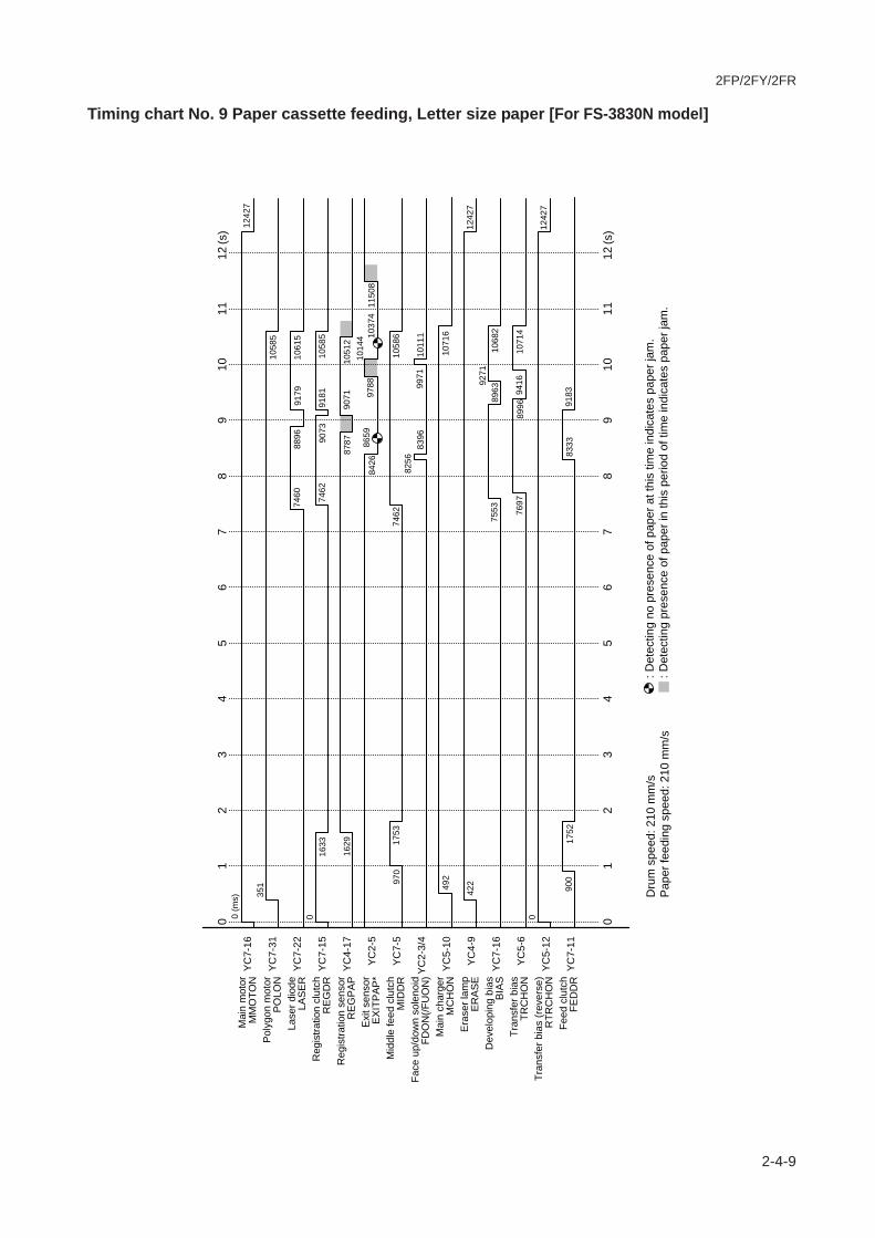
2FP/2FY/2FR
2-4-9
Timing chart No. 9 Paper cassette feeding, Letter size paper [For FS-3830N model]
(s)
(s)
0 (m
s)12
427
351
1058
5
7460
8896
9179
1061
50
9073
1633
7462
9181
1058
5
1629
1051
290
7187
87
1037
410
144
9788
1150
886
5984
26
970
1753
7462
1058
6
8396
8256
1011
199
71
492
1071
6
422
1242
7
7553
9271
8963
1068
2
7697
9416
8996
1071
40
1242
7
900
8333
1752
9183
12
34
56
78
910
1112
01
23
45
67
89
1011
12
0
Dru
m s
peed
: 210
mm
/sP
aper
feed
ing
spee
d: 2
10 m
m/s
: D
etec
ting
no p
rese
nce
of p
aper
at t
his
time
indi
cate
s pa
per j
am.
: Det
ectin
g pr
esen
ce o
f pap
er in
this
per
iod
of ti
me
indi
cate
s pa
per j
am.
Mai
n m
otor
MM
OTO
NY
C7-
16
YC
7-31
YC
7-22
YC
7-15
YC
4-17
YC
2-5
YC
7-5
YC
2-3/
4
YC
5-10
YC
4-9
YC
7-16
YC
5-6
YC
5-12
YC
7-11
Pol
ygon
mot
orP
OLO
NLa
ser d
iode
LAS
ER
Reg
istra
tion
clut
chR
EG
DR
Reg
istra
tion
sens
orR
EG
PA
PE
xit s
enso
rE
XIT
PA
P*
Mid
dle
feed
clu
tch
MID
DR
Face
up/
dow
n so
leno
idFD
ON
(/FU
ON
)M
ain
char
ger
MC
HO
NE
rase
r lam
pE
RA
SE
Dev
elop
ing
bias
BIA
STr
ansf
er b
ias
TRC
HO
NTr
ansf
er b
ias
(rev
erse
)R
TRC
HO
NFe
ed c
lutc
hFE
DD
R
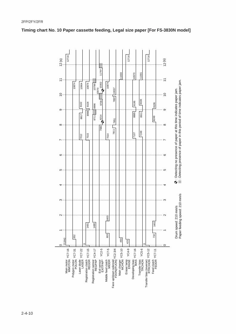
2FP/2FY/2FR
2-4-10
Timing chart No. 10 Paper cassette feeding, Legal size paper [For FS-3830N model]
0 (m
s)12
716
1271
6
1271
6
352
1087
4
7012
9102
8817
1090
40
8998
8711
8996
1481
7015
1087
4
1480
9104
1079
910
070
9706
7980
1030
211
797
8214
803
7014
1603
1087
4
7811
7897
7951
1003
7
493
1100
3
423
7107 72
49
9195
8885
1097
0
9339
8911
1100
10
732
8249
1602
9106
(s)
(s)
12
34
06
78
95
1112
10
12
34
06
78
95
1112
10
Dru
m s
peed
: 210
mm
/sP
aper
feed
ing
spee
d: 2
10 m
m/s
: D
etec
ting
no p
rese
nce
of p
aper
at t
his
time
indi
cate
s pa
per j
am.
: Det
ectin
g pr
esen
ce o
f pap
er in
this
per
iod
of ti
me
indi
cate
s pa
per j
am.
Mai
n m
otor
MM
OTO
NY
C7-
16
YC
7-31
YC
7-22
YC
7-15
YC
4-17
YC
2-5
YC
7-5
YC
2-3/
4
YC
5-10
YC
4-9
YC
7-16
YC
5-6
YC
5-12
YC
7-11
Pol
ygon
mot
orP
OLO
NLa
ser d
iode
LAS
ER
Reg
istra
tion
clut
chR
EG
DR
Reg
istra
tion
sens
orR
EG
PA
PE
xit s
enso
rE
XIT
PA
P*
Mid
dle
feed
clu
tch
MID
DR
Face
up/
dow
n so
leno
idFD
ON
(/FU
ON
)M
ain
char
ger
MC
HO
NE
rase
r lam
pE
RA
SE
Dev
elop
ing
bias
BIA
STr
ansf
er b
ias
TRC
HO
NTr
ansf
er b
ias
(rev
erse
)R
TRC
HO
NFe
ed c
lutc
hFE
DD
R

2FP/2FY/2FR
2-4-11
Timing chart No. 11 MP tray feeding, A4 size paper [For FS-3830N model]
0 (m
s)11
398
351
1055
5
1055
5
1055
5
7252
8954
8772
072
55
9059
9063
1358
1357
8952
1047
486
62
1002
8 1026
111
473
7255
8457
8216
809
9664
1461
1055
580
5199
5581
9399
96
493
1068
6
422
7348
9154
8839
1065
3
9298
7490
8873
1068
00
1239
8
1239
8
738
8362
812
8434
(s)
(s)
12
34
06
78
95
1112
10
12
34
06
78
95
1112
10
Dru
m s
peed
: 210
mm
/sP
aper
feed
ing
spee
d: 2
10 m
m/s
: D
etec
ting
no p
rese
nce
of p
aper
at t
his
time
indi
cate
s pa
per j
am.
: Det
ectin
g pr
esen
ce o
f pap
er in
this
per
iod
of ti
me
indi
cate
s pa
per j
am.
Mai
n m
otor
MM
OTO
NY
C7-
16
YC
7-31
YC
7-22
YC
7-15
YC
4-17
YC
2-5
YC
7-5
YC
2-3/
4
YC
5-10
YC
4-9
YC
7-16
YC
5-6
YC
5-12
Pol
ygon
mot
orP
OLO
NLa
ser d
iode
LAS
ER
Reg
istra
tion
clut
chR
EG
DR
Reg
istra
tion
sens
orR
EG
PA
PE
xit s
enso
rE
XIT
PA
P*
Mid
dle
feed
clu
tch
MID
DR
Face
up/
dow
n so
leno
idFD
ON
(/FU
ON
)M
ain
char
ger
MC
HO
NE
rase
r lam
pE
RA
SE
Dev
elop
ing
bias
BIA
STr
ansf
er b
ias
TRC
HO
NTr
ansf
er b
ias
(rev
erse
)R
TRC
HO
N
YC
7-3
MP
feed
sol
enoi
dM
PFS
OL

2FP/2FY/2FR
2-4-12
Timing chart No. 12 MP tray feeding, Letter size paper [For FS-3830N model]
0 (m
s)12
733
352
1089
3
7761
9198
9483
1092
30
9380
1347
7764
7764
9486
1089
3
1344
9091
1081
393
7310
090 10
447
1180
989
6487
2710
679
797
1450
1089
4
8559
1027
687
0110
416
492
1102
4
422
1273
3
7856
9575
9266
1099
1
7999
9720
9297
1101
90
1273
3
727
8786
799
8858
(s)
(s)
12
34
06
78
95
1112
10
12
34
06
78
95
1112
10
Dru
m s
peed
: 210
mm
/sP
aper
feed
ing
spee
d: 2
10 m
m/s
: D
etec
ting
no p
rese
nce
of p
aper
at t
his
time
indi
cate
s pa
per j
am.
: Det
ectin
g pr
esen
ce o
f pap
er in
this
per
iod
of ti
me
indi
cate
s pa
per j
am.
Mai
n m
otor
MM
OTO
NY
C7-
16
YC
7-31
YC
7-22
YC
7-15
YC
4-17
YC
2-5
YC
7-5
YC
2-3/
4
YC
5-10
YC
4-9
YC
7-16
YC
5-6
YC
5-12
Pol
ygon
mot
orP
OLO
NLa
ser d
iode
LAS
ER
Reg
istra
tion
clut
chR
EG
DR
Reg
istra
tion
sens
orR
EG
PA
PE
xit s
enso
rE
XIT
PA
P*
Mid
dle
feed
clu
tch
MID
DR
Face
up/
dow
n so
leno
idFD
ON
(/FU
ON
)M
ain
char
ger
MC
HO
NE
rase
r lam
pE
RA
SE
Dev
elop
ing
bias
BIA
STr
ansf
er b
ias
TRC
HO
NTr
ansf
er b
ias
(rev
erse
)R
TRC
HO
N
YC
7-3
MP
feed
sol
enoi
dM
PFS
OL

2FP/2FY/2FR
2-4-13
Timing chart No. 13 MP tray feeding, Legal size paper [For FS-3830N model]
0 (m
s)12
439
351
1059
8
6712
8513
8828
1062
90
8724
1318
6715
8831
1059
8
1317
8404
1052
087
22
7680
9406
1002
697
9511
521
7912
764
1142
367
1510
598
7507
9622
7649
9763
493
1072
8
422
1246
9
6805
8921
8580
1069
5
6950
9066
8611
1072
70
1243
976
780
9769
281
69
(s)
(s)
12
34
06
78
95
1112
10
12
34
06
78
95
1112
10
Dru
m s
peed
: 210
mm
/sP
aper
feed
ing
spee
d: 2
10 m
m/s
: D
etec
ting
no p
rese
nce
of p
aper
at t
his
time
indi
cate
s pa
per j
am.
: Det
ectin
g pr
esen
ce o
f pap
er in
this
per
iod
of ti
me
indi
cate
s pa
per j
am.
Mai
n m
otor
MM
OTO
NY
C7-
16
YC
7-31
YC
7-22
YC
7-15
YC
4-17
YC
2-5
YC
7-5
YC
2-3/
4
YC
5-10
YC
4-9
YC
7-16
YC
5-6
YC
5-12
Pol
ygon
mot
orP
OLO
NLa
ser d
iode
LAS
ER
Reg
istra
tion
clut
chR
EG
DR
Reg
istra
tion
sens
orR
EG
PA
PE
xit s
enso
rE
XIT
PA
P*
Mid
dle
feed
clu
tch
MID
DR
Face
up/
dow
n so
leno
idFD
ON
(/FU
ON
)M
ain
char
ger
MC
HO
NE
rase
r lam
pE
RA
SE
Dev
elop
ing
bias
BIA
STr
ansf
er b
ias
TRC
HO
NTr
ansf
er b
ias
(rev
erse
)R
TRC
HO
N
YC
7-3
MP
feed
sol
enoi
dM
PFS
OL
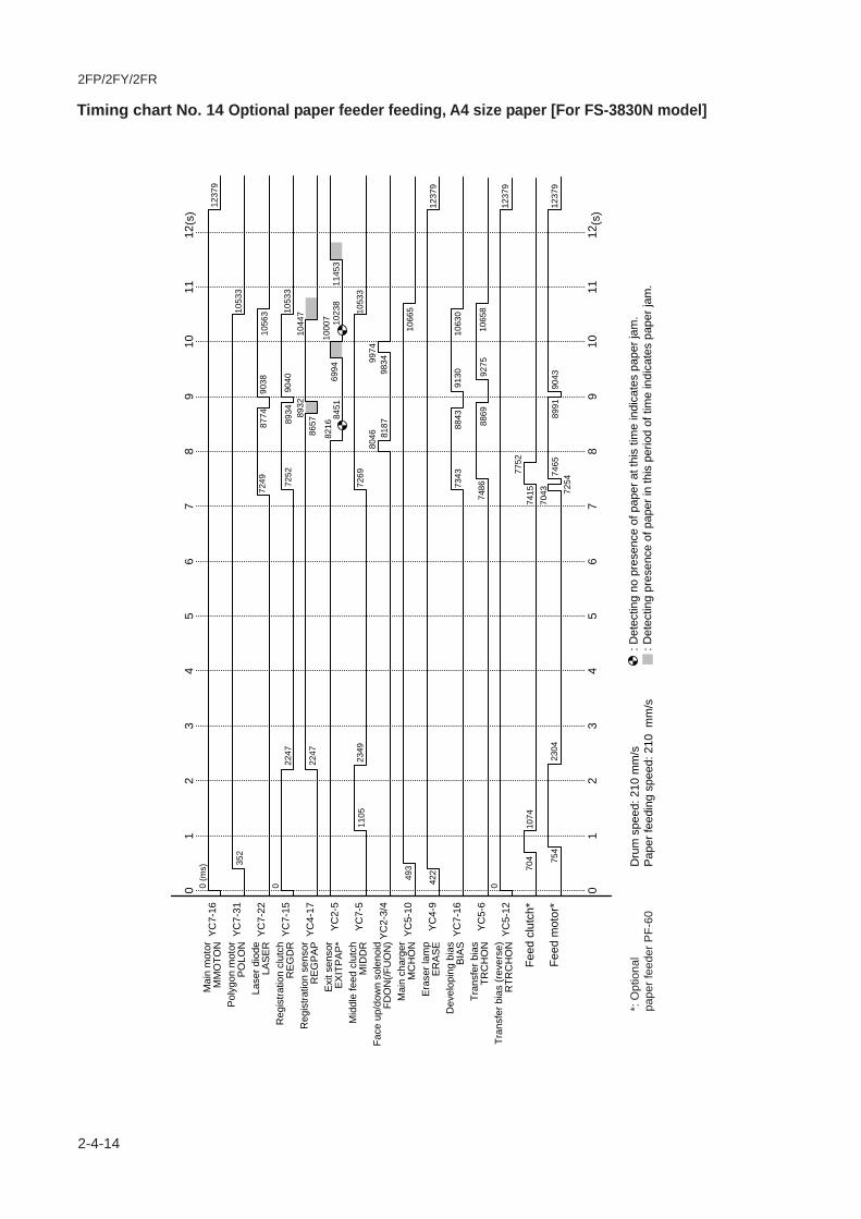
2FP/2FY/2FR
2-4-14
Timing chart No. 14 Optional paper feeder feeding, A4 size paper [For FS-3830N model]
0 (m
s)12
379
352
1053
3
1053
3
7249
8774
9038
1056
30
7252
8934
2247
2247
9040
8932
8657
7269
1044
7
1023
869
9410
007
1145
384
5182
16
1105
2349
1053
380
4698
3481
8799
74
493
1066
5
422
1237
9
1237
9
1237
9
7343
9130
8843
1063
0
7486
9275
8869
1065
80
704
7415
1074
7752
754
7043 72
5489
9123
0474
6590
43
(s)
(s)
12
34
06
78
95
1112
10
12
34
06
78
95
1112
10
Feed
clu
tch*
Feed
mot
or*
Dru
m s
peed
: 210
mm
/sP
aper
feed
ing
spee
d: 2
10 m
m/s
: D
etec
ting
no p
rese
nce
of p
aper
at t
his
time
indi
cate
s pa
per j
am.
: Det
ectin
g pr
esen
ce o
f pap
er in
this
per
iod
of ti
me
indi
cate
s pa
per j
am.
Mai
n m
otor
MM
OTO
NY
C7-
16
YC
7-31
YC
7-22
YC
7-15
YC
4-17
YC
2-5
YC
7-5
YC
2-3/
4
YC
5-10
YC
4-9
YC
7-16
YC
5-6
YC
5-12
Pol
ygon
mot
orP
OLO
NLa
ser d
iode
LAS
ER
Reg
istra
tion
clut
chR
EG
DR
Reg
istra
tion
sens
orR
EG
PA
PE
xit s
enso
rE
XIT
PA
P*
Mid
dle
feed
clu
tch
MID
DR
Face
up/
dow
n so
leno
idFD
ON
(/FU
ON
)M
ain
char
ger
MC
HO
NE
rase
r lam
pE
RA
SE
Dev
elop
ing
bias
BIA
STr
ansf
er b
ias
TRC
HO
NTr
ansf
er b
ias
(rev
erse
)R
TRC
HO
N
*: O
ptio
nal
pape
r fee
der P
F-60

2FP/2FY/2FR
2-4-15
Wiring diagram [For FS-1920 model]
+ -
1 2
1 21 2
123
FUDR+24V2FDDR
S02413
S03
024
S03
025
321
+5V2FDPFUL
GND
2
1
+5V1
THERM
S02
678
Ferr
ite c
ore
Ferritecore
Ferritecore
Ferr
iteco
re
Ferr
iteco
re
Ferr
ite c
ore
8� 7� 6� 5� 4� 3� 2� 1
1� 2� 3� 4� 5� 6� 7� 8
FDP
FUL*
+24V
3FU
DR
FDD
RE
XIT
PAP
*TH
ER
MG
ND
+5V
1
108642
129
147
16171813115
13151920
108642
129
1417167
1813115
13151920
+24V2REGDR*
DVFANDRGND
Opt
iona
l un
it I/F
co
nnec
tor
Par
alle
l I/F
Mai
n bo
ard
(KP-
1053
)
(YS
2)
(YS
1)
(YC
7)
(YC
8)
A20B20
A1B1
A1B1
A20B20
1�2�3�4
1�2
1�2
1�2�3�4
S02401
S02423
S02419
S03
017
S02405
+24V3GNDMMOTN*MMOTRDY*
Registrationclutch
(YC
803)
(YC
802)
(YC
810)
(YC
3)
+24V2FDDR*
1�2
1�2Feed clutch
(YC
804)
+24V2MPFSOL*MP Feed
solenoid
(YC
805)
+24V2MIDDR*Middle feed
clutch
(YC
806)
FANDRGND
Dev
elop
er
fan
mot
or
Coo
ling
fan
mot
or
(YC
807)
(YC
808)
(YC
801)
(YC
809)
LCD
con
trolle
r boa
rd(K
P-1
079)
Eng
ine
rela
y bo
ard
(KP
-107
1)Te
mpe
ratu
re/h
umid
ity
sens
or
6�5�4�3�2�1
123456
123
12345
12345
12345
1728394
105116
12
123
123
123456
+3.3V1FPDATA�FPDIR�FPCLK�GND�FPRST*
S02402
S03000
S03002
S02408
S02407
S02861S02410
S03022
Pin
pho
to d
iode
se
nsor
[boa
rd]
(KP
-107
5)
1234567
89
1234567
89
1�2
1�2
1�2
1�2
1�2
1�2
(YC
4)
(YC
1)
(YC
8)
(YC
2)
US
B
I/F(Y
C6)
+5V3PD*GND
POLCLKPOLRDY*�
POLON*�GND�
+24V3
POLCLKPOLRDY*�POLON*�GND�+24V2
Pol
ygon
mot
or
AP
C b
oard
(KP
-106
2)
(YC
602)
(YC
601)
Opt
iona
l uni
t I/F
con
nect
or
OP24VGNDOP5V(PFSEL)OPSCLKOPSEL0OPSDIOPSEL1OPSD0OPSEL2OPRDY*
18�17�16�15�14�13�12�11�10�9�8�7�6�5�4�3�2�1�
Eng
ine
boar
d(K
P-1
081)
Fuse
r boa
rd(K
P-1
069)
Top
cove
r/pap
er tr
ansf
erun
it in
terlo
ck s
witc
h
Left
cove
rin
terlo
cksw
itch
1�2�3�4�5�6�789
10
1�2�3�4
1�2�3�4�5�6�789
10
29�30�31�32�33�34
29�30�31�32�33�34
(YC
6)
GNDFPCLK�PFDIR�FPDATA+3.3V1FPRST*GNDFANDR+24V2MMOTON*GNDMMOTRDY*+24V2MPFSOL*FEDDR*MIDDR*+24V2REGDR*
+5V3SAMPLE*�
LASER*VDD+VOO-GND
PDIN*GND
19�20�21�22�2324�25�26�27�28
19�20�21�22�2324�25�26�27�28
AIRTEMP+5V1
WETCK1WETCK2
(YC
4)
(YC
209)
(YC
7)
(YC
704)
(YC
701)
(YC
703)
(YC702)
(YC
5)
4321
4321
12
12
1�2�3�45
1�2�
1�2�
(YC
3)(YC
10)
(YC831) (YC
834)
(YC
833)
(YC
832)
+24V
3
(YC
1)
+24V3CONTYPETMOTDR+5V2DLPTYPEHANDS*RTRCHON*HUNIT*MCHON*GNDHVCLKTONSCANTRCHON*TNEMP*TRVSEL3*+5V1TRVSEL1*TRVSEL2*
+24V1+24V1+24V1
+24V2+24V2+24V2
ERASEDRWTNLED*TNRFUL*
+5V2GNDEEDIOEECLKREGPAPPVOLAN1TCPVPFCPVP*CASIZEPVOLAN2
Sen
sor b
oard
(KP
-107
7)
4321
N.C. (GND)ERASEDRN.C. (GND)WTNLED*EECLKTNRFUL*EEDION.C. (+5V2)GND+5V2
Dru
m b
oard
(K
P-1
064)
(YC
741)
(YC
743)
(YC
742)
(YC
771)
(YC
761)
1
2
2
1
12
2�1
2�1
Was
teto
ner f
ull
sens
or [b
oard
](K
P-1
065)
Era
ser
lam
p [b
oard
](K
P-1
067)
S02411
S02412
+5V2
WTNLED*
ERASEDRGND
CAS0COMCAS1CAS2
24/2322/2120/1918/1716/1514/1312/1110/98/76/54/32/1
23/2421/2219/2017/1815/1613/1411/129/10
7/85/63/41/2
+24V1/+24V1+24V1/+24V1
GND/GNDGND/GND
+5V1/+5V1+5V1/+5V1
ZCROSS/HEATON*+24V3/
+5V2/GNDTHERM/EXITPAP*
FDDR/FUDR+24V2/FDPFUL*
(YC
2)
(YC901)
Pow
er s
uppl
y un
it
8� 7� 6� 5� 4� 3� 2� 1
1� 2� 3� 4� 5� 6� 7� 8
2
1
321
123
Was
teto
ner f
ull
sens
or(r
ecei
ver)
CE
Face
up
/dow
n so
leno
id
123
123
Pap
er fu
llse
nsor
Exi
t se
nsor
MP
tray
pape
rse
nsor
Opt
ion
feed
erse
nsor
Ther
mis
tor
Ther
mal
cut
out
Hea
ter l
amp
Con
trolle
run
it fa
n m
otor
BFANDR(+5V)GND
+5V1DBTX�DBRX�
DBCLK�GND
Hig
h vo
ltage
uni
t
1�2�
3�4�5�6�7�8�9
1�2�
3�4�5�6�7�8�9
98
7654321
98
7654321
TPMSCAN(GND)
TMOTDRGNDCOM
CNTYPE
Tone
rse
nsor
Pow
er
switc
h(YC
902)
(CN
2)
(CN1)
AC
inle
tA
Cin
put
+24V
2
OP
5V
12
12
Pap
ersi
ze s
witc
h
Tone
rm
otor
Exi
t rol
ler
OP
5V
OP
5V
1 2
Option DIMM Syst
em D
IMM
[boa
rd]
(KP-
1059
)
S03016
S02414
TONSCANGND�
TMOTDR�GND
Grid
Magnet roller
Transfer roller
1�2�3�4
1�2�3�4
108642
129
147
16171813115
1315
108642
129
147
16171813115
1315
1�2�3�4
1�2�3�4
1�2�3�4�5�6�7�8���
9�10�11�12�13�14�15�16�17�1819202122
1�2�3�4�5�6�7�8���
9�10�11�12�13�14�15�16�17�1819202122
1�2�3�4�5�6�789
1011121314
1�2�3�4�5�6�7�8�9�
10�11�12�13�14�15�16�17�18
1�2�3�4�5�6�7�8�9�
10�11�12�13�14�15�16�17�18
Zener board(KP-1073)
12
12
+24V2
+5V1OP24V
OP5V
123456789
101112
123456789
101112
1�2�3�4�
5�6�7
Top
cove
r sw
itch
Pap
er g
auge
se
nsor
1
Reg
istra
tion
sens
or
Pap
er g
auge
se
nsor
2
To P
F-60
, DU
-60
or H
S-6
0Compact
Flash
Microdrive
KU
IO-L
V
Netw
ork
inte
rface
card
(Opt
ion)
Mai
n m
otor
S03
014
: 120
V A
C m
odel
S03
013
: 220
- 24
0 V
AC
mod
el
Optionalmemorycard slot
Optionalhard diskdrive slot
(Cen
troni
cs)
(YC
651)
Seria
l I/F
card
(Opt
ion)
(RS
232C
)
(YC
11)
1
9

2FP/2FY/2FR
2-4-16
Wiring diagram [For FS-3820N model]
+ -
1 2
1 21 2
123
FUDR+24V2FDDR
S02413
S03
024
S03
025
321
+5V2FDPFUL
GND
2
1
+5V1
THERM
S02
678
Ferr
ite c
ore
Ferritecore
Ferritecore
Ferr
iteco
re
Ferr
iteco
re
Ferr
ite c
ore
8� 7� 6� 5� 4� 3� 2� 1
1� 2� 3� 4� 5� 6� 7� 8
FDP
FUL*
+24V
3FU
DR
FDD
RE
XIT
PAP
*TH
ER
MG
ND
+5V
1
108642
129
147
16171813115
13151920
108642
129
1417167
1813115
13151920
+24V2REGDR*
DVFANDRGND
Opt
iona
l un
it I/F
co
nnec
tor
Par
alle
l I/F
Net
-w
ork
Mai
n bo
ard
(KP-
1033
)
(YS
2)
(YS
1)
(YC
7)
(YC
8)
A20B20
A1B1
A1B1
A20B20
1�2�3�4
1�2
1�2
1�2�3�4
S03026
S02423
S02419
S03
017
S02405
+24V3GNDMMOTN*MMOTRDY*
Registrationclutch
(YC
803)
(YC
802)
(YC
810)
(YC
3)
+24V2FDDR*
1�2
1�2Feed clutch
(YC
804)
+24V2MPFSOL*MP Feed
solenoid
(YC
805)
+24V2MIDDR*Middle feed
clutch
(YC
806)
FANDRGND
Dev
elop
er
fan
mot
or
CP
Uco
olin
gfa
nm
otor
Coo
ling
fan
mot
or
(YC
807)
(YC
808)
(YC
801)
(YC
809)
LCD
con
trolle
r boa
rd(K
P-1
079)
Eng
ine
rela
y bo
ard
(KP
-107
1)Te
mpe
ratu
re/h
umid
ity
sens
or
6�5�4�3�2�1
123456
123
12345
12345
12345
1728394
105116
12
123
123
123456
+3.3V1FPDATA�FPDIR�FPCLK�GND�FPRST*
S02402
S03000
S03002
S02408
S02407
S02861S02410
S03022
Pin
pho
to d
iode
se
nsor
[boa
rd]
(KP
-107
5)
1234567
89
1234567
89
1�2
1�2
1�2
1�2
1�2
1�2
(YC
4)
(YC
1)
(YC
8)
(YC
2)(YC
6)
US
B
I/F(Y
C5)
+5V3PD*GND
POLCLKPOLRDY*�
POLON*�GND�
+24V3
POLCLKPOLRDY*�POLON*�GND�+24V2
Pol
ygon
mot
or
AP
C b
oard
(KP
-106
2)
(YC
602)
(YC
601)
Opt
iona
l uni
t I/F
con
nect
or
OP24VGNDOP5V(PFSEL)OPSCLKOPSEL0OPSDIOPSEL1OPSD0OPSEL2OPRDY*
18�17�16�15�14�13�12�11�10�9�8�7�6�5�4�3�2�1�
Eng
ine
boar
d(K
P-1
081)
Fuse
r boa
rd(K
P-1
069)
Top
cove
r/pap
er tr
ansf
erun
it in
terlo
ck s
witc
h
Left
cove
rin
terlo
cksw
itch
1�2�3�4�5�6�789
10
1�2�3�4
1�2�3�4�5�6�789
10
29�30�31�32�33�34
29�30�31�32�33�34
(YC
6)
GNDFPCLK�PFDIR�FPDATA+3.3V1FPRST*GNDFANDR+24V2MMOTON*GNDMMOTRDY*+24V2MPFSOL*FEDDR*MIDDR*+24V2REGDR*
+5V3SAMPLE*�
LASER*VDD+VOO-GND
PDIN*GND
19�20�21�22�2324�25�26�27�28
19�20�21�22�2324�25�26�27�28
AIRTEMP+5V1
WETCK1WETCK2
(YC
4)
(YC
209)
(YC
7)
(YC
704)
(YC
701)
(YC
703)
(YC702)
(YC
5)
4321
4321
12
12
1�2�3�45
1�2�
1�2�
1�2�
(YC
3)(YC
10)
(YC831) (YC
834)
(YC
833)
(YC
832)
+24V
3
(YC
1)
+24V3CONTYPETMOTDR+5V2DLPTYPEHANDS*RTRCHON*HUNIT*MCHON*GNDHVCLKTONSCANTRCHON*TNEMP*TRVSEL3*+5V1TRVSEL1*TRVSEL2*
+24V1+24V1+24V1
+24V2+24V2+24V2
ERASEDRWTNLED*TNRFUL*
+5V2GNDEEDIOEECLKREGPAPPVOLAN1TCPVPFCPVP*CASIZEPVOLAN2
Sen
sor b
oard
(KP
-107
7)
4321
N.C. (GND)ERASEDRN.C. (GND)WTNLED*EECLKTNRFUL*EEDION.C. (+5V2)GND+5V2
Dru
m b
oard
(K
P-1
064)
(YC
741)
(YC
743)
(YC
742)
(YC
771)
(YC
761)
1
2
2
1
12
2�1
2�1
Was
teto
ner f
ull
sens
or [b
oard
](K
P-1
065)
Era
ser
lam
p [b
oard
](K
P-1
067)
S02411
S02412
+5V2
WTNLED*
ERASEDRGND
CAS0COMCAS1CAS2
24/2322/2120/1918/1716/1514/1312/1110/98/76/54/32/1
23/2421/2219/2017/1815/1613/1411/129/10
7/85/63/41/2
+24V1/+24V1+24V1/+24V1
GND/GNDGND/GND
+5V1/+5V1+5V1/+5V1
ZCROSS/HEATON*+24V3/
+5V2/GNDTHERM/EXITPAP*
FDDR/FUDR+24V2/FDPFUL*
(YC
2)
(YC901)
Pow
er s
uppl
y un
it
8� 7� 6� 5� 4� 3� 2� 1
1� 2� 3� 4� 5� 6� 7� 8
2
1
321
123
Was
teto
ner f
ull
sens
or(r
ecei
ver)
CE
Face
up
/dow
n so
leno
id
123
123
Pap
er fu
llse
nsor
Exi
t se
nsor
MP
tray
pape
rse
nsor
Opt
ion
feed
erse
nsor
Ther
mis
tor
Ther
mal
cut
out
Hea
ter l
amp
Con
trolle
run
it fa
n m
otor
BFANDR(+5V)GND
+5V1DBTX�DBRX�
DBCLK�GND
Hig
h vo
ltage
uni
t
1�2�
3�4�5�6�7�8�9
1�2�
3�4�5�6�7�8�9
98
7654321
98
7654321
TPMSCAN(GND)
TMOTDRGNDCOM
CNTYPE
Tone
rse
nsor
Pow
er
switc
h(YC
902)
(CN
2)
(CN1)
AC
inle
tA
Cin
put
+24V
2
OP
5V
12
12
Pap
ersi
ze s
witc
h
Tone
rm
otor
Exi
t rol
ler
OP
5V
OP
5V
1 2
Option DIMM Syst
em D
IMM
[boa
rd]
(KP-
893)
S03016
S02414
TONSCANGND�
TMOTDR�GND
Grid
Magnet roller
Transfer roller
1�2�3�4
1�2�3�4
108642
129
147
16171813115
1315
108642
129
147
16171813115
1315
1�2�3�4
1�2�3�4
1�2�3�4�5�6�7�8���
9�10�11�12�13�14�15�16�17�1819202122
1�2�3�4�5�6�7�8���
9�10�11�12�13�14�15�16�17�1819202122
1�2�3�4�5�6�789
1011121314
1�2�3�4�5�6�7�8�9�
10�11�12�13�14�15�16�17�18
1�2�3�4�5�6�7�8�9�
10�11�12�13�14�15�16�17�18
Zener board(KP-1073)
12
12
+24V2
+5V1OP24V
OP5V
123456789
101112
123456789
101112
1�2�3�4�
5�6�7
Top
cove
r sw
itch
Pap
er g
auge
se
nsor
1
Reg
istra
tion
sens
or
Pap
er g
auge
se
nsor
2
To P
F-60
, DU
-60
or H
S-6
0
CompactFlash
Microdrive
KU
IO-L
V
Netw
ork
inte
rface
card
(Opt
ion)
Mai
n m
otor
S03
014
: 120
V A
C m
odel
S03
013
: 220
- 24
0 V
AC
mod
el
Optionalmemorycard slot
Optionalhard diskdrive slot
(Cen
troni
cs)
(YC
651)
Seria
l I/F
card
(Opt
ion)
(RS
232C
)
(YC
11)
1
9

2FP/2FY/2FR
2-4-17
Wiring diagram [For FS-3830N model]
+ -
1 2
1 21 2
123
FUDR+24V2FDDR
S02413
S03
024
S03
025
321
+5V2FDPFUL
GND
2
1
+5V1
THERM
S02
678
Ferr
ite c
ore
Ferritecore
Ferritecore
Ferr
iteco
re
Ferr
iteco
re
Ferr
ite c
ore
8� 7� 6� 5� 4� 3� 2� 1
1� 2� 3� 4� 5� 6� 7� 8
FDP
FUL*
+24V
3FU
DR
FDD
RE
XIT
PAP
*TH
ER
MG
ND
+5V
1
108642
129
147
16171813115
13151920
108642
129
1417167
1813115
13151920
+24V2REGDR*
DVFANDRGND
Opt
iona
l un
it I/F
co
nnec
tor
Par
alle
l I/F
Net
-w
ork
Mai
n bo
ard
(KP-
1033
)
*1 : For
FS-
1920
mod
el*2 : F
or F
S-38
20N
mod
el*3 : F
or F
S-38
30N
mod
el
(YS
3)(Y
S2)
(YS
1)
(YC
7)
(YC
8)
A20B20
A1B1
A1B1
A20B20
1�2�3�4
1�2
1�2
1�2�3�4
S02401
S02423
S02419
S03
017
S02405
+24V3GNDMMOTN*MMOTRDY*
Registrationclutch
(YC
803)
(YC
802)
(YC
810)
(YC
3)
+24V2FDDR*
1�2
1�2Feed clutch
(YC
804)
+24V2MPFSOL*MP Feed
solenoid
(YC
805)
+24V2MIDDR*Middle feed
clutch
(YC
806)
FANDRGND
Dev
elop
er
fan
mot
or
CP
Uco
olin
gfa
nm
otor
Coo
ling
fan
mot
or
(YC
807)
(YC
808)
(YC
801)
(YC
809)
LCD
con
trolle
r boa
rd(K
P-1
079)
Eng
ine
rela
y bo
ard
(KP
-107
1)Te
mpe
ratu
re/h
umid
ity
sens
or
6�5�4�3�2�1
123456
123
12345
12345
12345
1728394
105116
12
123
123
123456
+3.3V1FPDATA�FPDIR�FPCLK�GND�FPRST*
S02402
S03000
S03003
S02408
S02407
S02861S02410
S03022
Pin
pho
to d
iode
se
nsor
[boa
rd]
(KP
-107
5)
1234567
89
1234567
89
1�2
1�2
1�2
1�2
1�2
1�2
(YC
4)
(YC
1)
(YC
8)
(YC
2)(YC
6)
US
B
I/F(Y
C5)
+5V3PD*GND
POLCLKPOLRDY*�
POLON*�GND�
+24V3
POLCLKPOLRDY*�POLON*�GND�+24V2
Pol
ygon
mot
or
AP
C b
oard
(KP
-106
2)
(YC
602)
(YC
601)
Opt
iona
l uni
t I/F
con
nect
or
OP24VGNDOP5V(PFSEL)OPSCLKOPSEL0OPSDIOPSEL1OPSD0OPSEL2OPRDY*
18�17�16�15�14�13�12�11�10�9�8�7�6�5�4�3�2�1�
Eng
ine
boar
d(K
P-1
081)
Fuse
r boa
rd(K
P-1
069)
Top
cove
r/pap
er tr
ansf
erun
it in
terlo
ck s
witc
h
Left
cove
rin
terlo
cksw
itch
1�2�3�4�5�6�789
10
1�2�3�4
1�2�3�4�5�6�789
10
29�30�31�32�33�34
29�30�31�32�33�34
(YC
6)
GNDFPCLK�PFDIR�FPDATA+3.3V1FPRST*GNDFANDR+24V2MMOTON*GNDMMOTRDY*+24V2MPFSOL*FEDDR*MIDDR*+24V2REGDR*
+5V3SAMPLE*�
LASER*VDD+VOO-GND
PDIN*GND
19�20�21�22�2324�25�26�27�28
19�20�21�22�2324�25�26�27�28
AIRTEMP+5V1
WETCK1WETCK2
(YC
4)
(YC
209)
(YC
7)
(YC
704)
(YC
701)
(YC
703)
(YC702)
(YC
5)
4321
4321
12
12
1�2�3�45
1�2�
1�2�
1�2�
(YC
3)(YC
10)
(YC831) (YC
834)
(YC
833)
(YC
832)
+24V
3
(YC
1)
+24V3CONTYPETMOTDR+5V2DLPTYPEHANDS*RTRCHON*HUNIT*MCHON*GNDHVCLKTONSCANTRCHON*TNEMP*TRVSEL3*+5V1TRVSEL1*TRVSEL2*
+24V1+24V1+24V1
+24V2+24V2+24V2
ERASEDRWTNLED*TNRFUL*
+5V2GNDEEDIOEECLKREGPAPPVOLAN1TCPVPFCPVP*CASIZEPVOLAN2
Sen
sor b
oard
(KP
-107
7)
4321
N.C. (GND)ERASEDRN.C. (GND)WTNLED*EECLKTNRFUL*EEDION.C. (+5V2)GND+5V2
Dru
m b
oard
(K
P-1
064)
(YC
741)
(YC
743)
(YC
742)
(YC
771)
(YC
761)
1
2
2
1
12
2�1
2�1
Was
teto
ner f
ull
sens
or [b
oard
](K
P-1
065)
Era
ser
lam
p [b
oard
](K
P-1
067)
S02411
S02412
+5V2
WTNLED*
ERASEDRGND
CAS0COMCAS1CAS2
24/2322/2120/1918/1716/1514/1312/1110/98/76/54/32/1
23/2421/2219/2017/1815/1613/1411/129/10
7/85/63/41/2
+24V1/+24V1+24V1/+24V1
GND/GNDGND/GND
+5V1/+5V1+5V1/+5V1
ZCROSS/HEATON*+24V3/
+5V2/GNDTHERM/EXITPAP*
FDDR/FUDR+24V2/FDPFUL*
(YC
2)
(YC901)
Pow
er s
uppl
y un
it
8� 7� 6� 5� 4� 3� 2� 1
1� 2� 3� 4� 5� 6� 7� 8
2
1
321
123
Was
teto
ner f
ull
sens
or(r
ecei
ver)
CE
Face
up
/dow
n so
leno
id
123
123
Pap
er fu
llse
nsor
Exi
t se
nsor
MP
tray
pape
rse
nsor
Opt
ion
feed
erse
nsor
Ther
mis
tor
Ther
mal
cut
out
Hea
ter l
amp
Con
trolle
run
it fa
n m
otor
BFANDR(+5V)GND
+5V1DBTX�DBRX�
DBCLK�GND
Hig
h vo
ltage
uni
t
1�2�
3�4�5�6�7�8�9
1�2�
3�4�5�6�7�8�9
98
7654321
98
7654321
TPMSCAN(GND)
TMOTDRGNDCOM
CNTYPE
Tone
rse
nsor
Pow
er
switc
h(YC
902)
(CN
2)
(CN1)
AC
inle
tA
Cin
put
+24V
2
OP
5V
12
12
Pap
ersi
ze s
witc
h
Tone
rm
otor
Exi
t rol
ler
OP
5V
OP
5V
1 2
Option DIMM
Option DIMM
Syst
em D
IMM
[boa
rd]
(KP-
893)
S03016
S02414
TONSCANGND�
TMOTDR�GND
Grid
Magnet roller
Transfer roller
1�2�3�4
1�2�3�4
108642
129
147
16171813115
1315
108642
129
147
16171813115
1315
1�2�3�4
1�2�3�4
1�2�3�4�5�6�7�8���
9�10�11�12�13�14�15�16�17�1819202122
1�2�3�4�5�6�7�8���
9�10�11�12�13�14�15�16�17�1819202122
1�2�3�4�5�6�789
1011121314
1�2�3�4�5�6�7�8�9�
10�11�12�13�14�15�16�17�18
1�2�3�4�5�6�7�8�9�
10�11�12�13�14�15�16�17�18
Zener board(KP-1073)
12
12
+24V2
+5V1OP24V
OP5V
123456789
101112
123456789
101112
1�2�3�4�
5�6�7
Top
cove
r sw
itch
Pap
er g
auge
se
nsor
1
Reg
istra
tion
sens
or
Pap
er g
auge
se
nsor
2
To P
F-60
, DU
-60
or H
S-6
0Compact
Flash
Microdrive
KU
IO-L
V
Netw
ork
inte
rface
card
(Opt
ion)
Mai
n m
otor
S03
014
: 120
V A
C m
odel
S03
013
: 220
- 24
0 V
AC
mod
el
Optionalmemorycard slot
Optionalhard diskdrive slot
(Cen
troni
cs)
(YC
651)
Seria
l I/F
card
(Opt
ion)
(RS
232C
)
(YC
11)
1
9

2FP/2FY/2FR
2-4-18
First occurrence of defect
[63 mm] Developing roller (Process unit)
[25 mm] Upper registration roller
[38 mm] Lower registration roller
[61 mm] Heat roller, Press roller (Fuser unit)
[94 mm] Drum (Process unit)
[50 mm] Transfer roller
Repetitive defects gauge

2FP/2FY/2FR
2-4-19
This page is intentionally left blank.

MEMO:

MEMO:

MEMO:


![Untitled-2 [] · FS 78 FS 68 , FOCUS ÉkJ ËFOCUS FS 78 FS 68 FS 68 , , , FS 68 Foundation FS 68 , FS 68 68 fi , FOCUS F-s 688 , , 68 , 688 FOCUS FS , FS 68 , , , 688 ,](https://img.dokumen.tips/doc/110x75/5b75f9b67f8b9a3b7e8b5e04/untitled-2-fs-78-fs-68-focus-ekj-efocus-fs-78-fs-68-fs-68-fs-68.jpg)