Embed Size (px)
Citation preview
Fibre reinforced polymer for strengthening cylindrical metal shellsagainst elephant’s foot buckling: An elasto-plastic analysis
Batikha, M., Chen, J. F., & Rotter, J. M. (2018). Fibre reinforced polymer for strengthening cylindrical metalshells against elephant’s foot buckling: An elasto-plastic analysis. Advances in Structural Engineering, 21(16),2483-2498. https://doi.org/10.1177/1369433218817139
Published in:Advances in Structural Engineering
Document Version:Peer reviewed version
Queen's University Belfast - Research Portal:Link to publication record in Queen's University Belfast Research Portal
Publisher rightsCopyright 2018 SAGE. This work is made available online in accordance with the publisher’s policies. Please refer to any applicable terms ofuse of the publisher.
General rightsCopyright for the publications made accessible via the Queen's University Belfast Research Portal is retained by the author(s) and / or othercopyright owners and it is a condition of accessing these publications that users recognise and abide by the legal requirements associatedwith these rights.
Take down policyThe Research Portal is Queen's institutional repository that provides access to Queen's research output. Every effort has been made toensure that content in the Research Portal does not infringe any person's rights, or applicable UK laws. If you discover content in theResearch Portal that you believe breaches copyright or violates any law, please contact [email protected].
Download date:23. Feb. 2022
FRP for Strengthening Cylindrical Metal Shells against Elephant’s Foot Buckling – An Elasto-Plastic Analysis
M. Batikha 1, J.F. Chen 2,3,* and J.M. Rotter 4
1. Assistant Professor, School of Energy, Geoscience, Infrastructure and Society, Heriot-
Watt University-Dubai Campus, Dubai, UAE 2. Distinguished Professor, College of Architecture and Civil Engineering, Wenzhou
University, Wenzhou, China 3. Professor, School of Natural and Built Environment, Queen’s University Belfast, Belfast
BT9 5AG, UK 4. Emeritus Professor, School of Engineering, The University of Edinburgh, Edinburgh
EH9 3JL, UK * Corresponding author. Email: [email protected], tel. +44 28 9097 4184
Abstract: This paper describes the use of Fibre Reinforced Polymer (FRP) composites to increase the strength of an isotropic metallic cylindrical shell against elephant’s foot buckling. This form of buckling occurs when a cylindrical shell structure is subjected to high internal pressure together with an axial force, such as those that may occur in tanks and silos. It is particularly relevant to tanks under seismic action. Although FRP composites have been widely applied to different types of structures under several loading conditions, its use to strengthen thin steel cylindrical shells has been very limited. Here, a non-linear elasto-plastic finite element idealization is used to explore the strengthening effect of an FRP strip on a thin cylinder. The optimum size and position of the FRP sheet were obtained and empirically formulated. This study has shown that the strength after repair is sensitive to minor changes in the FRP-parameters so that a close adherence to the optimum parameter values is very desirable. Keyword: Elephant’s foot buckling, FRP, shells, strengthening, non-linear analysis, silos, tanks.
1. Introduction Elephant’s foot is the term commonly used to describe a local elastic-plastic buckling failure that occurs at the base of a cylindrical shell structure that is subjected to high internal pressure together with an axial force. This type of buckling failure is common in tanks after they have been damaged by earthquakes due to the axial forces induced by overturning moments (Rotter, 1990, 2006). Cyclic loading may cause an elephant's foot buckle to extend around the complete circumference at the bottom of the tank wall (Subhan et al., 2017; Djermane et al., 2014). Elephant's foot buckling can also be predicted for non-empty thin silos under wind loads (Zhao et al., 2013; Cao et al., 2018). A local buckle forms adjacent to the boundary, where the effects of local bending are amplified by co-existent axial compression (Rotter, 1989). It may be noted that smaller internal pressures increase the buckling strength under axial compression (Teng and
Rotter 1992; Rotter 2004), but the first demonstration that this effect is limited by elephant’s foot buckling was given by Rotter (1990). The first theoretical investigation of elephant’s foot buckling for both pinned-base and fixed-base cylinders was published by Rotter (1990). His proposed semi-empirical design expressions are now widely used in codes of practice (EN 1993-1-6, 2007; EN 1993-4-1, 2007; EN 1998-4, 2006; NZS-2654, 1989). Rotter showed that a clamped base can provide a significant increase in strength in very thin cylinders; but that the strength is similar for both pinned and fixed bases in thicker cylinders. An alternative treatment for design purposes was also developed by Rotter (2006). More recently, Kildashti et al. (2018) showed by a nonlinear time history analysis that there seems to be little difference in buckling resistance between the pinned and fixed base conditions if the tank is susceptible to elephant 's foot buckling under dynamic loading. One technique to strengthen a cylindrical tank or silo against elephant’s foot buckling is to use a ring stiffener. Chen et al. (2005, 2006) proposed that a small discrete metal ring stiffener could considerably improve a tank’s resistance to elephant's foot buckling. The optimum dimensions and location for this stiffener were derived, based on linear elastic shell bending theory (Timoshenko and Woinowsky-Krieger 1959; Rotter, 1985a). It was shown that if the ring stiffener has either a size or a location different from the optimum condition, the enhancement in the buckling strength that it provides can easily be lost. External bonding of fibre reinforced polymer (FRP) composites have been an effective strengthening method for different types of structures under various loading scenarios (Teng et al 2002, Teng and Chen 2009). Kumar and Senthil (2016a; b) investigated the behaviour of an FRP-strengthened slender element of steel circular hollow sections (CHS) under axial loading, and observed a significant improvement in ductility, stiffness, and loading capacity. The loading capacity and the energy dissipation of concrete-filled steel cylinders under axial and lateral loadings can also be significantly enhanced by confining them with FRP (Lu et al, 2014; Zhu et al, 2018). In this case the steel tube wall is under internal pressure due to the expansion of concrete which also prevents its inward buckling, while its outwards buckling is restrained by the FRP. However, there is still very little published work on FRP-strengthened thin steel cylinders (Teng et al., 2012). Teng and Hu (2004, 2007) studied the wrapping of thicker cylinders (R/t=19) with FRP to resist axisymmetric plastic buckling failures under pure axial compression (also described as elephant’s foot, although the conditions are slightly different from those found in tanks and silos). Batikha et al. (2007a; 2009) studied a thin silo (R/t=1000) strengthened by FRP against elephant's foot buckling under an axial load accompanied by internal pressure. In that study the optimum location and size of the FRP strengthening were derived using an elastic analysis. However, the accuracy of that study may be limited since plasticity could play a significant role in elephant’s foot buckling. The present study thus extends the work presented in Batikha et al. (2007a; 2009) by adopting a Geometrically and Materially Non-linear Analysis (GMNA) to devise proposals that accurately describe the great benefits of FRP in preventing elasto-plastic collapse at a tank base. It may be noted that the preliminary results of this study were presented in a conference (Batikha et al. 2007b), where it was shown that FRP is an effective remedy.
2. Finite element modelling
The general-purpose finite element program ABAQUS (Ver 6.12-1) was used for the analysis. A steel cylinder with a height h of 5000 mm, radius R of 5000 mm and thickness ts of 5 mm was modelled as the reference case. The radius to thickness ratio R/t was 1000, producing a medium-length cylinder according to EN 1993-1-6 (2007). The values of Young’s modulus, Es, and Poisson’s ratio, νs, of the steel were taken as 200 GPa and 0.3 respectively. The steel was assumed to have an elastic-perfectly-plastic stress-strain relationship with a yield stress of fy = 250 N/mm2. A uniform internal pressure p and a vertical load per unit circumference Nz were applied to the cylinder. The base of the cylinder was restrained in the radial and axial directions. The top edge of the cylinder was restrained against rotation. Under axisymmetric loading, these boundary conditions ensure that buckling occurs at the base and model a cylinder that is much longer than the extent of the local deformations involved in elephant’s foot buckling (Rotter and Teng, 1989). The cylinder was modelled using the 2-node axisymmetric general-purpose shell element SAX1 which includes transverse shear deformation (ABAQUS/Standard User’s Manual, 2012). Each node has three degrees of freedom (radial and axial displacements and rotation about the circumferential axis). An axisymmetric element was justified as only axisymmetric collapse was observed in previous studies that included checks for non-symmetric bifurcation (Rotter, 1990, 2006). Non-linear elasto-plastic finite element analysis was performed. The Riks arc-length method was used (Riks 1979) to trace the nonlinear response after buckling. A mesh convergence study was conducted, from which an element size of was chosen. Such an element size is far
smaller than that used by Rotter and Teng (1989) and Rotter and Zhang (1990), where cubic elements of size were used.
3. Buckling strength of thin cylindrical shells without strengthening For a uniform metal cylindrical shell without any strengthening to resist elephant’s foot buckling, an upper bound to the strength may be taken as the condition where the von Mises effective stress is reached on the outside surface of the shell: = ( + ) − ( + ) × ( + ) + ( + ) (1) in which σmz is the meridional membrane stress, σmθ is the circumferential membrane stress, and σbz is the meridional bending stress. The latter two stresses are usually dominant in Eq. (1) when the internal pressure is high. The von Mises stress, σvM0 is used as the reference value, which
0.02 sRt
0.25 sRt
refers to the state where the bending moment is zero and the lateral displacement, w, is equal to the membrane theory normal deflection wm: = ( + ) (2)
The axial stress at first yield when the characteristic elephant’s foot shape develops can be predicted by Rotter’s (1989) approximation to the exact solution for the non-linear elastic bending equations: = + 0.3 2.725 + .√ − 2.65 = (3)
in which the normalised meridional membrane stress: = (4)
where σcl is the classical elastic buckling stress of thin cylindrical shells given by: = ( ) ≈ 0.605 (5)
Rotter (1989, 1990) derived the following semi-empirical equations to describe the elephant’s foot buckling strength under elastic-plastic conditions. These have been widely adopted into codes of practice (e.g. EN 1993-1-6, 2007; ECCS, 2008): = 1 − 1 − . . (6) = (7)
The conditions leading to elastic bifurcation buckling under pure axial compression in other parts of an imperfect shell have been reviewed by Rotter (2004) and are defined in EN 1993-1-6 (2007). The amplitude of the imperfection affects this strength, and the reduced strength is commonly written as: = . (8) where αz is the meridional elastic imperfection factor. An empirical lower bound for the relationship between this imperfection factor and the imperfection amplitude is used in EN 1993-1-6 (2007) as: = .. ( / ) . (9)
in which is the characteristic imperfection amplitude. Since the imperfection amplitude is affected by both the quality of fabrication and the radius to thickness ratio, the amplitude is defined in EN 1993-1-6 (2007), taken from Rotter (1985b), as: = (10)
where, Q is the meridional compression fabrication quality parameter (Table 1).
kwΔ
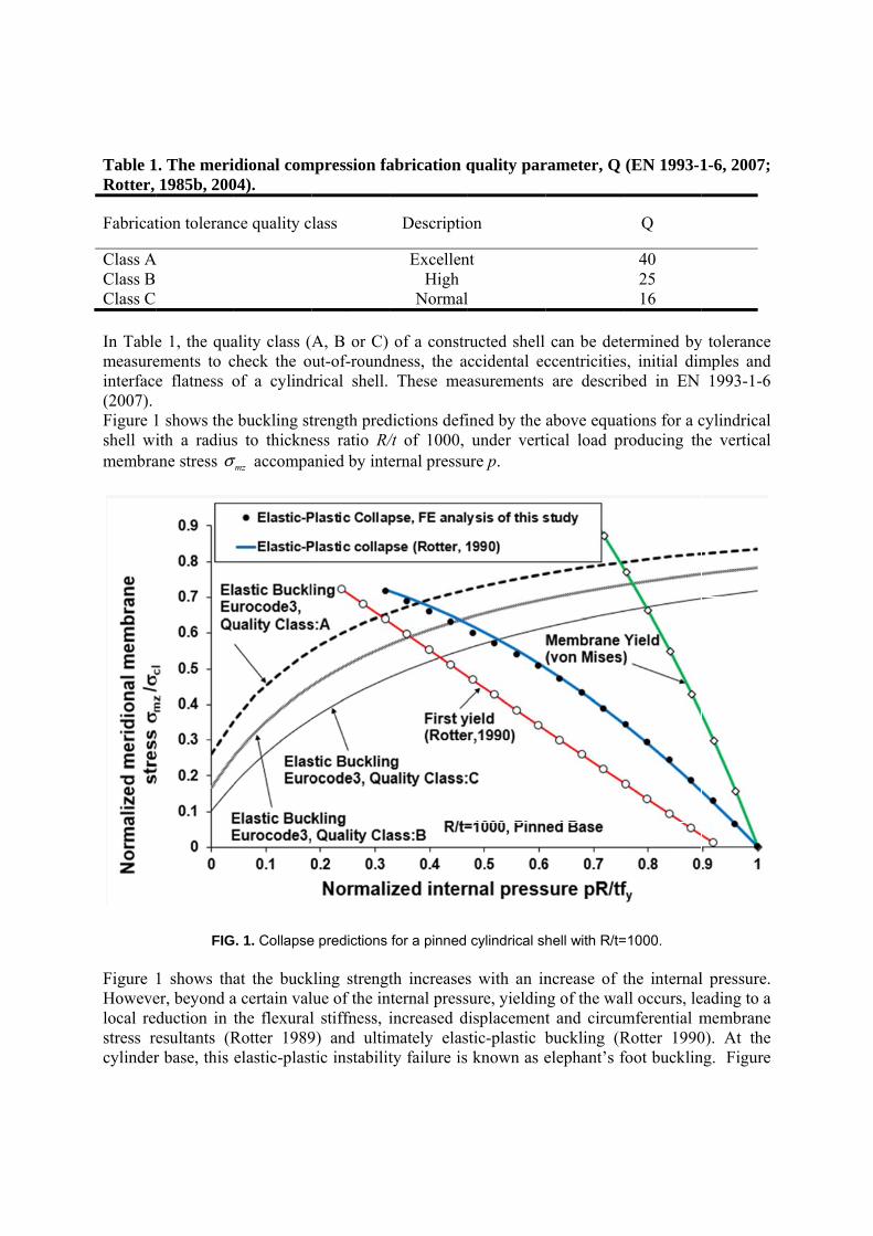
Table 1Rotter,
Fabricat
Class AClass B Class C In Tablemeasureinterface(2007). Figure 1shell wimembra
Figure Howevelocal restress rcylinder
1. The meri1985b, 200
tion toleranc
A
e 1, the quaements to ce flatness o
1 shows the ith a radiusane stress
FIG
1 shows thaer, beyond aduction in tesultants (Rr base, this
σ
idional com04).
ce quality c
ality class (Acheck the oof a cylind
buckling sts to thickne
accompa
G. 1. Collapse
at the bucka certain valthe flexuralRotter 1989elastic-plast
mzσ
mpression fa
lass
A, B or C) ut-of-round
drical shell.
trength predess ratio R/anied by inte
e predictions
kling strengtlue of the inl stiffness, i9) and ultimtic instabilit
abrication q
Descriptio
ExcellenHigh
Normal
of a constrdness, the a
These mea
dictions defi/t of 1000, ernal pressu
for a pinned
th increasesnternal pressincreased dmately elasty failure is
quality par
on
nt
ructed shell ccidental ecasurements
ined by the under verti
ure p.
cylindrical sh
s with an insure, yieldindisplacementstic-plastic b known as e
rameter, Q
can be detccentricitiesare describ
above equatical load pr
hell with R/t=
ncrease of tng of the wat and circumbuckling (Relephant’s f
(EN 1993-1
Q
40 25 16
ermined bys, initial dimbed in EN
tions for a croducing th
=1000.
the internalall occurs, lemferential mRotter 1990foot bucklin
1-6, 2007;
y tolerance mples and
1993-1-6
cylindrical he vertical
l pressure. eading to a membrane 0). At the ng. Figure
1 shows that the elastic-plastic collapse strengths obtained from a FE analysis in the present study are in very close agreement with those predicted by Eq. 6 developed by Rotter (1990).
4. FRP strengthened cylindrical shells
4.1. Modelling For the example cylinder, an FRP sheet with a height of hf was bonded to the external surface of the cylindrical shell, starting at the level xf above the base. The FRP sheet was treated as orthotropic with Young’s modulus Efθ in the circumferential direction and Efz in the meridional direction, and Poisson’s ratios νfθz and νfzθ . The FRP lamina was modelled using the element SAX1, a 2-node axisymmetric shell element. The model assumed a perfect bond between the cylinder and the FRP sheet. 4.2. Verification of the model To verify the FE model, the FE predictions are compared with the experimental results of Teng and Hu (2004, 2007) as shown in Fig. 2. The experimental study of Teng and Hu (2004, 2007) was to demonstrate the effectiveness of FRP confinement on thick steel tubes using a GFRP jacket. The experimental setup of a fixed-base steel tube with height h = 450mm, radius R = 80.4mm and thickness ts = 4.2mm was modelled. The steel had a Young’s modulus Es of 201GPa, Poisson’s ratio νs of 0.3 and yield stress of 335 MPa with strain hardening modulus of 5% of the elastic value. It should be noted that the tube is considered thick, with an R/t ratio of about 19. The 0.53mm thick (tf) three-ply GFRP jacket was modelled over the entire height of the tube as in the experiment. The GFRP sheet was modelled as an orthotropic material with Efθ = 80.1GPa, Efz = 3 GPa, νfθz =0.35 and νfzθ =0.013. It is worth mentioning that Teng and Hu modelled their tests using the B33 element in ABAQUS (Version 6.12-1) oriented in the hoop direction to model the FRP and S4R shell elements to model the tube. B33 is a bi-cubic beam element with six degrees of freedom per node. The height of the B33 element was taken as the height of the shell element. S4R is 4-node doubly curved general-purpose shell, with reduced integration with hourglass control and the effect of transverse shear deformation included. Each node has six degrees of freedom, comprising of three displacements and three rotations. Figure 2 shows the experimental load-deflection curves for a pair of experiments with and without GFRP strengthening. The test loading capacity was 782.2 kN for the former and 717.5 kN for the latter. The finite element curves of Teng and Hu are also shown, together with the curves predicted from the FE model in this study. Teng and Hu modelled the GFRP using beam elements and predicted a loading capacity of 800 and 709 kN respectively for the specimens with and without FRP strengthening. The GFRP was modelled using shell elements here and the predicted corresponding loading capacities were 787 and 709 kN respectively when the vertical stiffness of the FRP was neglected (Efz = 0). Clearly the loading capacities predicted by both FE models are very close to the test values. All results show that the GFRP strengthening increased
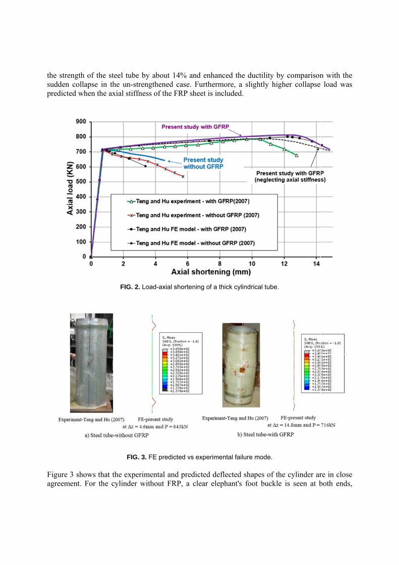
the strensudden predicte
Figure 3agreeme
ngth of the collapse in
ed when the
3 shows thaent. For the
steel tube bn the un-stre
axial stiffn
FIG. 2. L
FIG. 3
at the experie cylinder w
by about 14engthened cess of the F
Load-axial sh
3. FE predict
imental andwithout FRP
4% and enhcase. FurtheRP sheet is
hortening of a
ted vs experi
d predicted dP, a clear e
hanced the dermore, a slincluded.
a thick cylind
mental failure
deflected shelephant's fo
ductility by lightly high
drical tube.
e mode.
hapes of theoot buckle i
comparisonher collapse
e cylinder aris seen at b
n with the load was
re in close both ends,
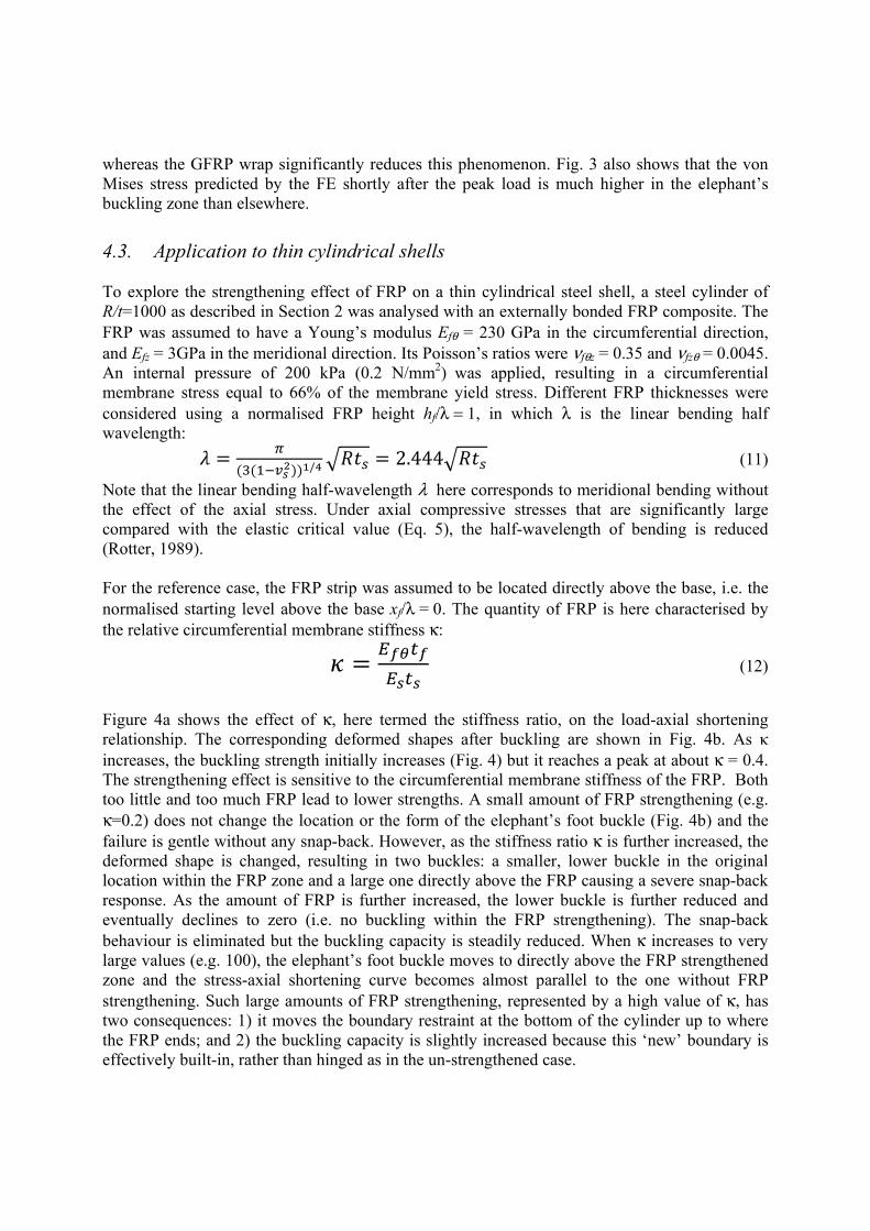
whereas the GFRP wrap significantly reduces this phenomenon. Fig. 3 also shows that the von Mises stress predicted by the FE shortly after the peak load is much higher in the elephant’s buckling zone than elsewhere.
4.3. Application to thin cylindrical shells To explore the strengthening effect of FRP on a thin cylindrical steel shell, a steel cylinder of R/t=1000 as described in Section 2 was analysed with an externally bonded FRP composite. The FRP was assumed to have a Young’s modulus Efθ = 230 GPa in the circumferential direction, and Efz = 3GPa in the meridional direction. Its Poisson’s ratios were νfθz = 0.35 and νfzθ = 0.0045. An internal pressure of 200 kPa (0.2 N/mm2) was applied, resulting in a circumferential membrane stress equal to 66% of the membrane yield stress. Different FRP thicknesses were considered using a normalised FRP height hf/λ = 1, in which λ is the linear bending half wavelength: = ( ( )) / = 2.444 (11)
Note that the linear bending half-wavelength λ here corresponds to meridional bending without the effect of the axial stress. Under axial compressive stresses that are significantly large compared with the elastic critical value (Eq. 5), the half-wavelength of bending is reduced (Rotter, 1989). For the reference case, the FRP strip was assumed to be located directly above the base, i.e. the normalised starting level above the base xf/λ = 0. The quantity of FRP is here characterised by the relative circumferential membrane stiffness κ:
= (12)
Figure 4a shows the effect of κ, here termed the stiffness ratio, on the load-axial shortening relationship. The corresponding deformed shapes after buckling are shown in Fig. 4b. As κ increases, the buckling strength initially increases (Fig. 4) but it reaches a peak at about κ = 0.4. The strengthening effect is sensitive to the circumferential membrane stiffness of the FRP. Both too little and too much FRP lead to lower strengths. A small amount of FRP strengthening (e.g. κ=0.2) does not change the location or the form of the elephant’s foot buckle (Fig. 4b) and the failure is gentle without any snap-back. However, as the stiffness ratio κ is further increased, the deformed shape is changed, resulting in two buckles: a smaller, lower buckle in the original location within the FRP zone and a large one directly above the FRP causing a severe snap-back response. As the amount of FRP is further increased, the lower buckle is further reduced and eventually declines to zero (i.e. no buckling within the FRP strengthening). The snap-back behaviour is eliminated but the buckling capacity is steadily reduced. When κ increases to very large values (e.g. 100), the elephant’s foot buckle moves to directly above the FRP strengthened zone and the stress-axial shortening curve becomes almost parallel to the one without FRP strengthening. Such large amounts of FRP strengthening, represented by a high value of κ, has two consequences: 1) it moves the boundary restraint at the bottom of the cylinder up to where the FRP ends; and 2) the buckling capacity is slightly increased because this ‘new’ boundary is effectively built-in, rather than hinged as in the un-strengthened case.
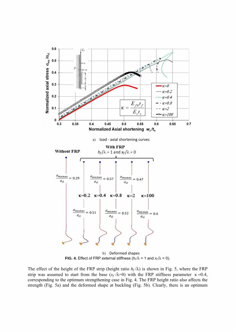
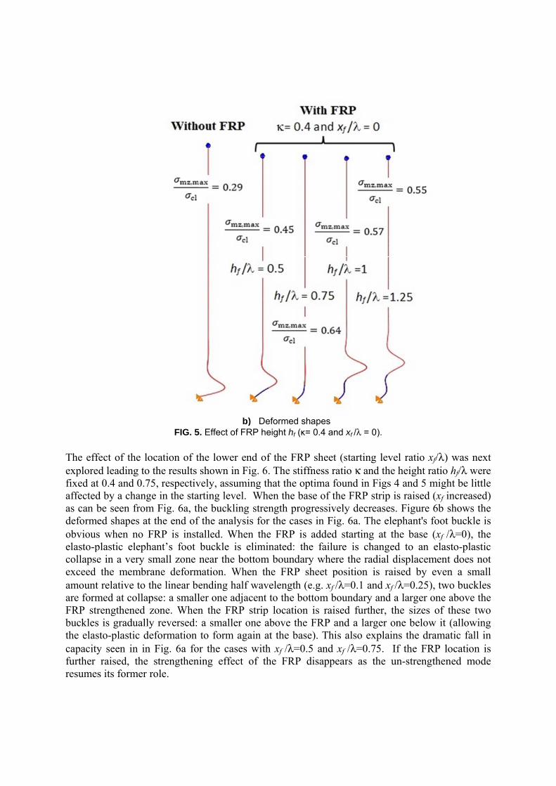
The effestrip wacorrespostrength
fect of the has assumed onding to thh (Fig. 5a) a
FIG. 4. Effe
height of thed to start frohe optimum and the def
a) load
b)ect of FRP ex
e FRP strip om the basstrengtheni
formed shap
d - axial shor
) Deformedxternal stiffne
(height ratise (xf /λ=0) ing case in Fpe at buckli
rtening curve
d shapes ess (hf /λ = 1
io hf /λ) is with the F
Fig. 4. The ing (Fig. 5b
es
and xf /λ = 0
shown in FFRP stiffnesFRP height
b). Clearly,
).
ig. 5, wheress parametet ratio also athere is an
e the FRP er κ =0.4, affects the
n optimum
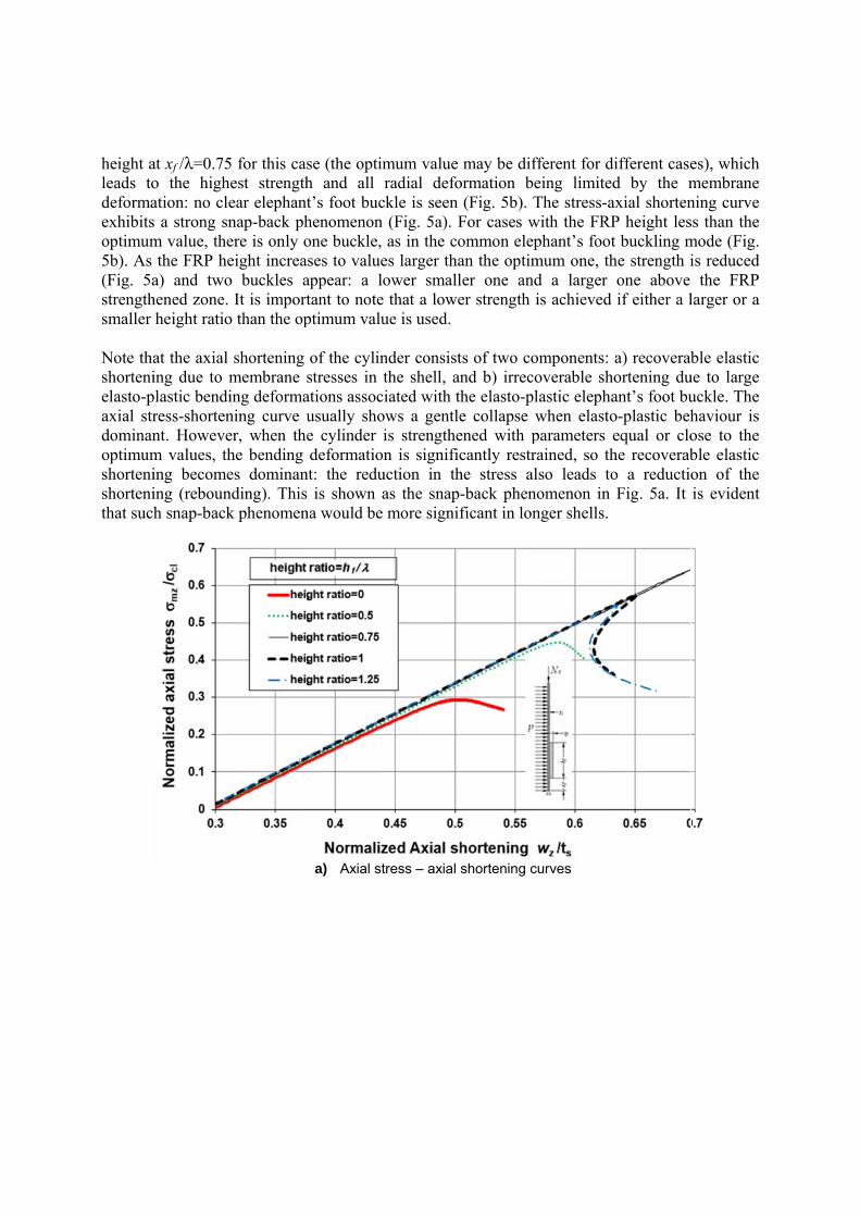
height aleads todeformaexhibitsoptimum5b). As (Fig. 5astrengthsmaller Note thashortenielasto-paxial strdominanoptimumshortenishortenithat such
at xf /λ=0.75o the highation: no cles a strong snm value, thethe FRP he
a) and twohened zone. height ratio
at the axial ing due to m
plastic bendiress-shortennt. Howevem values, thing becomeing (rebounh snap-back
5 for this casest strengthear elephantnap-back phere is only oeight increao buckles a
It is importo than the op
shortening membrane sing deformaning curve uer, when thehe bending es dominannding). Thisk phenomen
se (the optimh and all t’s foot buchenomenon one buckle,ses to value
appear: a lotant to note ptimum valu
of the cylinstresses in tations assocusually shoe cylinder ideformation
nt: the redu is shown a
na would be
a) Axial st
mum value radial defo
ckle is seen (Fig. 5a). Fas in the co
es larger thaower small that a loweue is used.
nder consistthe shell, aniated with th
ows a gentleis strengthen is signific
uction in thas the snap-more signif
tress – axial s
may be difformation be
(Fig. 5b). TFor cases wommon elepan the optimler one ander strength i
ts of two cond b) irrecohe elasto-ple collapse wened with pcantly restrahe stress al-back phenoficant in lon
shortening c
fferent for dieing limitedThe stress-a
with the FRPphant’s footmum one, thd a larger is achieved
omponents: overable sholastic elephawhen elastoparameters eained, so thlso leads toomenon in nger shells.
urves
ifferent cased by the m
axial shortenP height lest buckling mhe strength ione above if either a l
a) recoverabortening duant’s foot buo-plastic behequal or clohe recoverabo a reductioFig. 5a. It
es), which membrane ning curve ss than the mode (Fig. is reduced
the FRP larger or a
ble elastic ue to large uckle. The haviour is ose to the ble elastic on of the is evident
The effeexploredfixed at affectedas can bdeformeobviouselasto-pcollapseexceed amount are formFRP strbuckles the elascapacityfurther resumes
fect of the lod leading to0.4 and 0.7
d by a changbe seen fromed shapes ats when no Fplastic elephe in a very sthe membrrelative to t
med at collaprengthened
is graduallyto-plastic d
y seen in inraised, the
s its former
FIG. 5
ocation of to the results 75, respectivge in the stam Fig. 6a, tht the end of FRP is insthant’s foot small zone rane deformthe linear bepse: a smallzone. Wheny reversed:
deformation n Fig. 6a fo
strengthenrole.
b)5. Effect of FR
the lower enshown in F
vely, assumiarting level. he bucklingf the analysitalled. Whenbuckle is enear the bo
mation. Wheending half ler one adjan the FRP a smaller oto form aga
or the cases ning effect
) DeformedRP height hf
nd of the FRig. 6. The sting that the When the b
g strength pris for the can the FRP eliminated: ottom bounden the FRP
f wavelengthacent to the bstrip locatio
one above thain at the bwith xf /λ=
of the FRP
d shapes (κ= 0.4 and x
RP sheet (stiffness ratiooptima founbase of the rogressivelyases in Fig.is added stthe failure
dary where tP sheet posh (e.g. xf /λ=bottom bounon is raisedhe FRP andase). This a
=0.5 and xf /P disappear
xf /λ = 0).
tarting leveo κ and the nd in Figs 4FRP strip is
y decreases.6a. The eleptarting at th
is changedthe radial dition is rais
=0.1 and xf /ndary and a
d further, thd a larger onalso explain/λ=0.75. Ifrs as the un
el ratio xf/λ)height ratio
4 and 5 mighs raised (xf i Figure 6b phant's foot
he base (xf /d to an elasdisplacemensed by eve/λ=0.25), twa larger one he sizes of ne below it
ns the dramaf the FRP ln-strengthen
) was next o hf/λ were ht be little increased) shows the t buckle is /λ=0), the sto-plastic
nt does not n a small
wo buckles above the these two (allowing
atic fall in location is ned mode
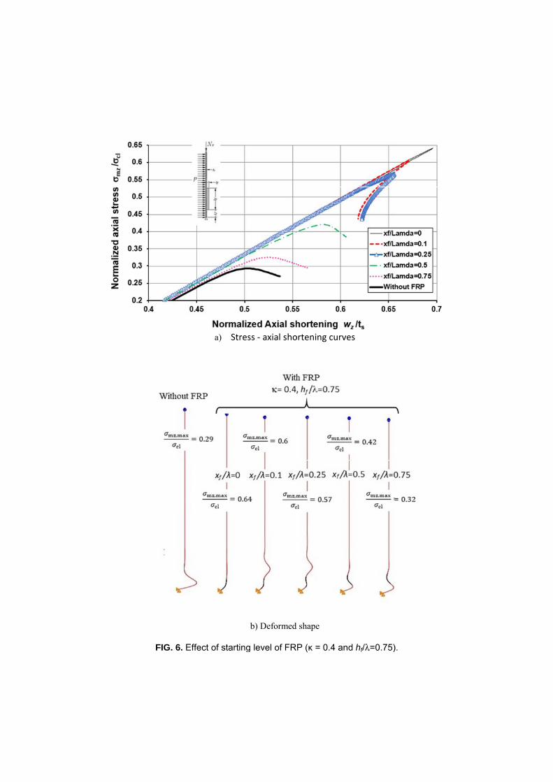
FIG. 6. Effe
a) Stre
ect of starting
ss - axial sho
b) Deformed
g level of FR
ortening curv
d shape
RP (κ = 0.4 an
ves
nd hf/λ=0.75)
).
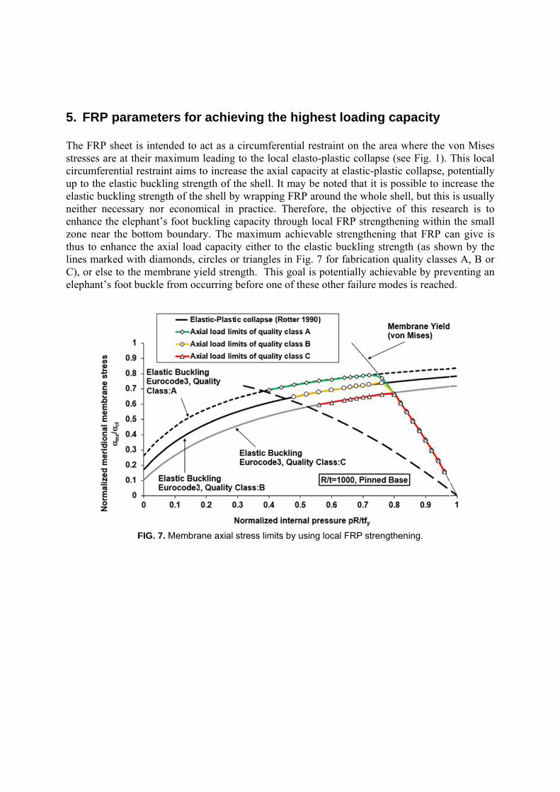
5. FR The FRstresses circumfup to thelastic bneither enhancezone nethus to lines maC), or eelephan
P param
RP sheet is inare at their
ferential resthe elastic bubuckling strenecessary n
e the elephaear the bottoenhance thearked with dlse to the m
nt’s foot buc
FIG
eters for
ntended to r maximum traint aims t
uckling strenength of thenor econom
ant’s foot buom boundare axial loaddiamonds, c
membrane yikle from oc
G. 7. Membra
r achievin
act as a circleading to
to increase ngth of the e shell by wmical in prauckling capary. The max
d capacity ecircles or triield strength
ccurring befo
ane axial stre
ng the hi
cumferentiathe local elthe axial cashell. It ma
wrapping FRactice. Theracity througximum ach
either to theiangles in Fh. This goa
fore one of th
ess limits by u
ighest lo
al restraint oasto-plastic
apacity at elay be notedRP around threfore, the gh local FRPhievable stre elastic buc
Fig. 7 for faal is potentihese other f
using local F
oading ca
on the area collapse (sastic-plasticthat it is po
he whole shobjective oP strengthenengthening ckling strengabrication qually achievafailure mode
RP strengthe
apacity
where the vsee Fig. 1). c collapse, possible to inell, but this
of this reseaning withinthat FRP cagth (as showuality classeable by preves is reached
ening.
von Mises This local potentially ncrease the
is usually arch is to
n the small an give is wn by the es A, B or venting an d.
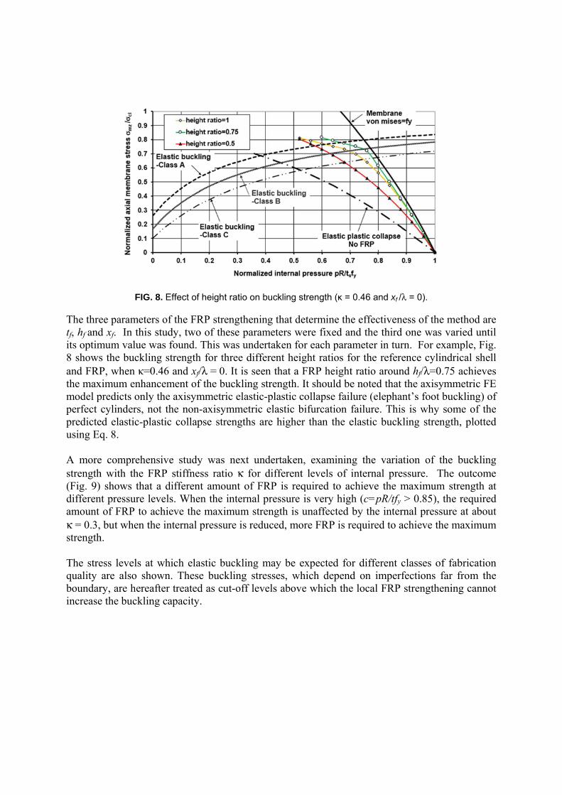
The thretf, hf andits optim8 showsand FRPthe maxmodel pperfect predicteusing Eq A morestrength(Fig. 9)differenamount κ = 0.3,strength The strequality boundarincrease
FIG
ee parameted xf. In thismum value ws the buckliP, when κ=0
ximum enhapredicts onlycylinders, n
ed elastic-plq. 8.
e comprehenh with the F shows that
nt pressure lof FRP to but when th
h.
ess levels atare also shry, are hereae the bucklin
. 8. Effect of
ers of the FRs study, twowas found. Ting strength0.46 and xf/
ancement of y the axisymnot the non-lastic collap
nsive studyFRP stiffnest a differentevels. Whenachieve thehe internal p
t which elahown. Theseafter treatedng capacity.
height ratio o
RP strengtheo of these paThis was un
h for three d/λ = 0. It isf the bucklinmmetric elas-axisymmetpse strength
y was next ss ratio κ ft amount ofn the intern maximum pressure is r
stic buckline buckling d as cut-off .
on buckling s
ening that dearameters wndertaken fodifferent heiseen that a
ng strength.stic-plastic ctric elastic bhs are highe
undertakenfor differentf FRP is req
nal pressurestrength is
reduced, mo
ng may be estresses, whlevels abov
strength (κ =
etermine thewere fixed anor each paraight ratios foFRP heightIt should be
collapse failbifurcation fr than the e
n, examinint levels of iquired to acis very highunaffected
ore FRP is r
expected fohich depend
ve which the
0.46 and xf /
e effectivennd the third
ameter in turfor the refert ratio aroune noted that lure (elephafailure. Thielastic buck
ng the variainternal prechieve the mh (c=pR/tfy by the inter
required to a
r different cd on imperfe local FRP
/λ = 0).
ness of the md one was varn. For examence cylindnd hf/λ=0.75
the axisymant’s foot bus is why so
kling strengt
ation of theessure. Themaximum s> 0.85), th
rnal pressurachieve the m
classes of ffections farstrengtheni
method are aried until mple, Fig.
drical shell 5 achieves
mmetric FE uckling) of ome of the th, plotted
e buckling e outcome strength at e required
re at about maximum
fabrication r from the ing cannot
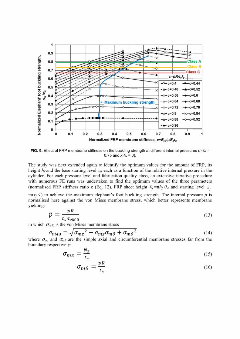
FIG. 9.
The stuheight hcylinderwith nu(normal
=πxf /λ) normaliyielding
in which
where σboundar
Effect of FR
dy was nexhf and the bar. For each umerous FElised FRP s
to achieve sed here ag
g: =h σvM0 is the=σmz and σm
ry respectiv
RP membrane
xt extended ase startingpressure le
E runs was stiffness rati
the maximgainst the v
0
e von Mises=θ are the siely: =
e stiffness on0.
again to id level xf, eavel and fabundertaken
io κ (Eq. 12
mum elephanvon Mises
s membrane−imple axial
=
n the buckling75 and xf /λ =
dentify the oach as a funbrication quan to find th2), FRP she
nt’s foot bumembrane
stress +l and circum
g strength at = 0).
optimum vanction of theality class, e optimum eet height h
uckling strestress, whi
mferential m
different inte
alues for thee relative inan extensivvalues of
fh =πhf /λb a
ength. The iich better r
membrane s
ernal pressur
e amount onternal pressve iterative the three pand starting
internal prerepresents m
stresses far
res (hf /λ =
f FRP, its sure in the procedure
parameters g level fx
essure p is membrane
(13)
(14) r from the
(15)
(16)
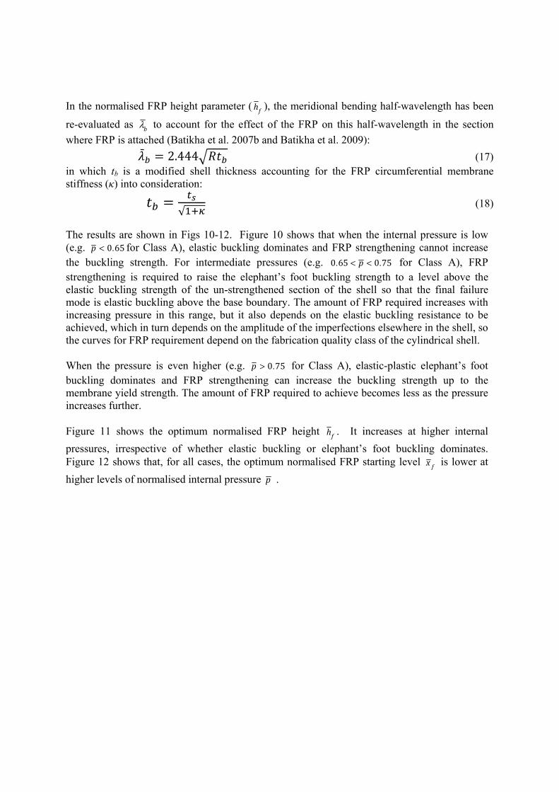
In the normalised FRP height parameter ( fh ), the meridional bending half-wavelength has been
re-evaluated as bλ to account for the effect of the FRP on this half-wavelength in the section
where FRP is attached (Batikha et al. 2007b and Batikha et al. 2009): = 2.444 (17) in which tb is a modified shell thickness accounting for the FRP circumferential membrane stiffness (κ) into consideration: = √ (18)
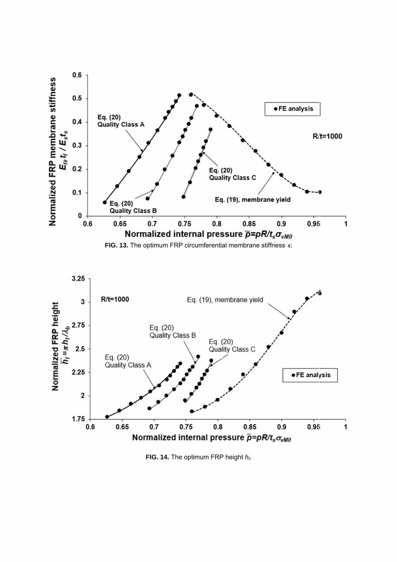
The results are shown in Figs 10-12. Figure 10 shows that when the internal pressure is low (e.g. 0 65.p < for Class A), elastic buckling dominates and FRP strengthening cannot increase the buckling strength. For intermediate pressures (e.g. 0 65 0 75. .p< < for Class A), FRP strengthening is required to raise the elephant’s foot buckling strength to a level above the elastic buckling strength of the un-strengthened section of the shell so that the final failure mode is elastic buckling above the base boundary. The amount of FRP required increases with increasing pressure in this range, but it also depends on the elastic buckling resistance to be achieved, which in turn depends on the amplitude of the imperfections elsewhere in the shell, so the curves for FRP requirement depend on the fabrication quality class of the cylindrical shell. When the pressure is even higher (e.g. 0 75.p > for Class A), elastic-plastic elephant’s foot buckling dominates and FRP strengthening can increase the buckling strength up to the membrane yield strength. The amount of FRP required to achieve becomes less as the pressure increases further. Figure 11 shows the optimum normalised FRP height fh . It increases at higher internal
pressures, irrespective of whether elastic buckling or elephant’s foot buckling dominates. Figure 12 shows that, for all cases, the optimum normalised FRP starting level fx is lower at
higher levels of normalised internal pressure p .
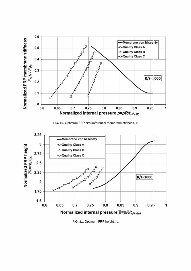
FIG. 10. Opptimum FRP
FIG. 11. O
circumferent
Optimum FR
tial membran
P height, hf.
ne stiffness, κκ.
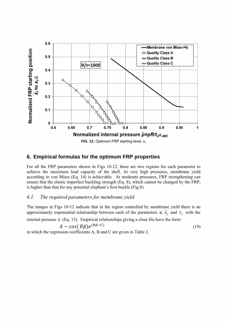
6. Em
For all achieve accordinensure tis highe
6.1. T The imaapproxim
internal
in which
mpirical fo
the FRP pathe maxim
ng to von Mthat the elaser than that f
The requir
ages in Figsmately expo
pressure p
h the regres
ormulas
arameters shmum load cMises (Eq. 1stic imperfecfor any pote
red param
s 10-12 indonential rel
(Eq. 13). E− (sion coeffic
FIG. 12. Opt
for the o
hown in Figcapacity of14) is achiect buckling
ential elepha
meters for m
dicate that inlationship b
Empirical re ) ( cients A, B a
timum FRP s
optimum
gs 10-12, thf the shell. evable. At strength (E
ant’s foot bu
membrane
n the regionetween each
elationships) and C are gi
starting level,
FRP pro
here are twAt very h
moderate pq. 8), which
uckle (Fig.8
e yield
n controlledh of the pa
s giving a clo
iven in Tabl
xf.
operties
wo regions fhigh pressurressures, FRh cannot be ).
d by membrarameters κ,
ose fits hav
le 2.
for each parres, membrRP strengthchanged by
rane yield t, fh and fx
e the form:
rameter to rane yield hening can y the FRP,
there is an
f with the
(19)
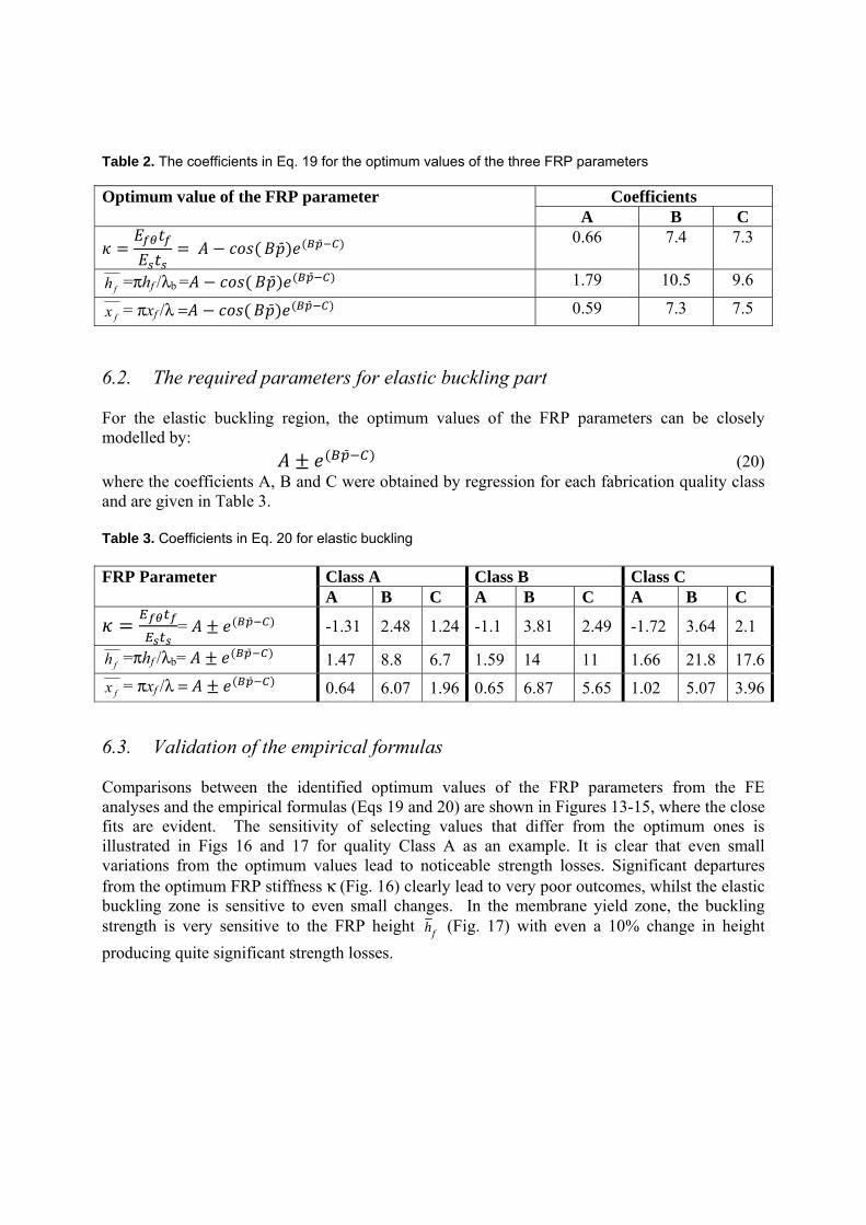
Table 2. The coefficients in Eq. 19 for the optimum values of the three FRP parameters
Optimum value of the FRP parameter Coefficients A B C = = − ( ) ( ) 0.66 7.4 7.3
=πhf /λb = − ( ) ( ) 1.79 10.5 9.6
= πxf /λ = − ( ) ( ) 0.59 7.3 7.5
6.2. The required parameters for elastic buckling part For the elastic buckling region, the optimum values of the FRP parameters can be closely modelled by: ± ( ) (20) where the coefficients A, B and C were obtained by regression for each fabrication quality class and are given in Table 3. Table 3. Coefficients in Eq. 20 for elastic buckling FRP Parameter Class A Class B Class C
A B C A B C A B C = = ± ( ) -1.31 2.48 1.24 -1.1 3.81 2.49 -1.72 3.64 2.1
=πhf /λb= ± ( ) 1.47 8.8 6.7 1.59 14 11 1.66 21.8 17.6
= πxf /λ = ± ( ) 0.64 6.07 1.96 0.65 6.87 5.65 1.02 5.07 3.96
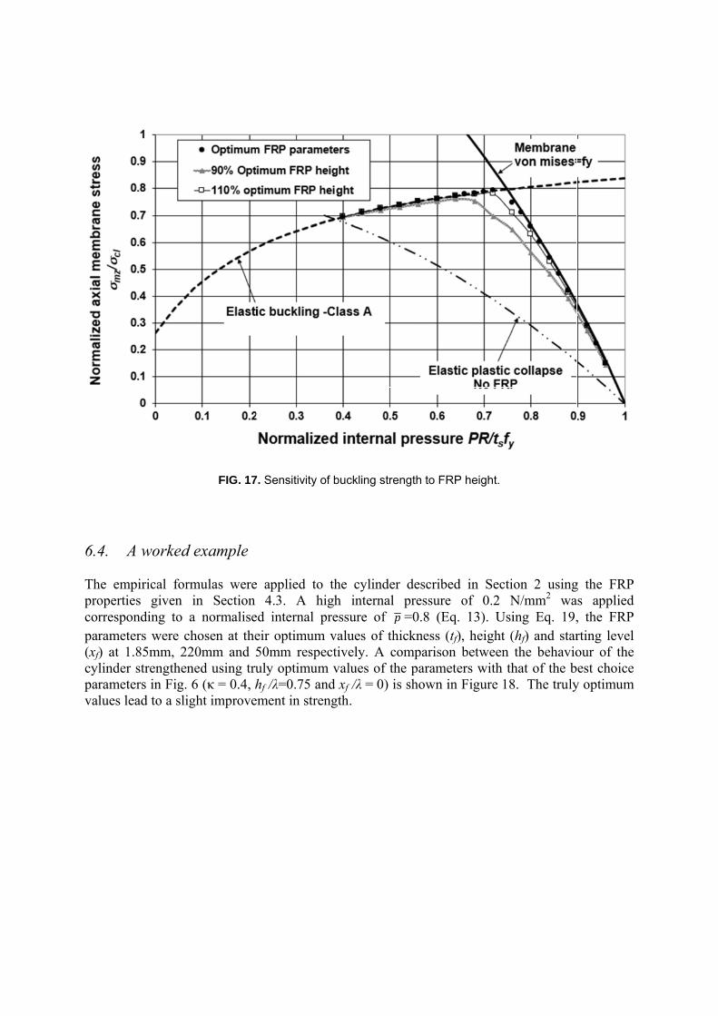
6.3. Validation of the empirical formulas Comparisons between the identified optimum values of the FRP parameters from the FE analyses and the empirical formulas (Eqs 19 and 20) are shown in Figures 13-15, where the close fits are evident. The sensitivity of selecting values that differ from the optimum ones is illustrated in Figs 16 and 17 for quality Class A as an example. It is clear that even small variations from the optimum values lead to noticeable strength losses. Significant departures from the optimum FRP stiffness κ (Fig. 16) clearly lead to very poor outcomes, whilst the elastic buckling zone is sensitive to even small changes. In the membrane yield zone, the buckling strength is very sensitive to the FRP height fh (Fig. 17) with even a 10% change in height
producing quite significant strength losses.
fh
fx
fh
fx
FFIG. 13. The optimum FR
FIG. 14. Th
RP circumfere
he optimum F
ential membr
FRP height h
rane stiffness
hf.
s κ.
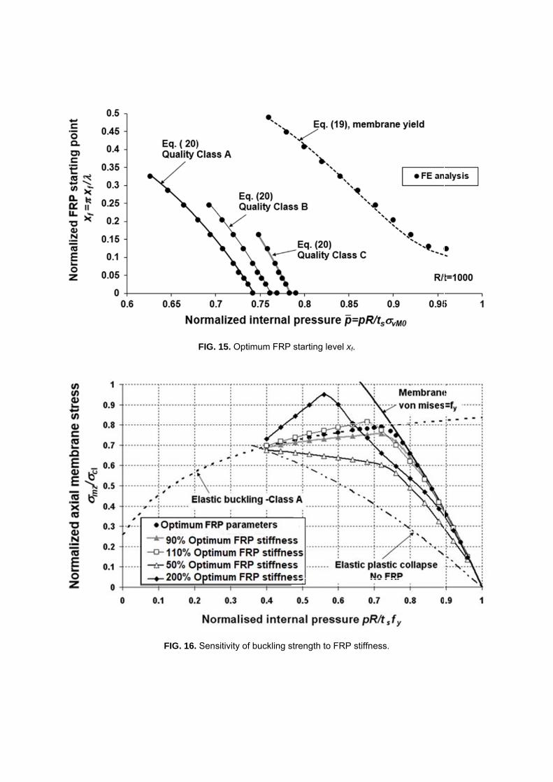
FIG. 16.
FIG. 15. Opt
Sensitivity o
timum FRP s
of buckling str
starting level
rength to FR
xf.
P stiffness.
6.4. A The emproperticorrespoparamet(xf) at 1cylinderparametvalues l
A worked
mpirical formies given onding to aters were ch1.85mm, 22r strengthenters in Fig. 6ead to a slig
FIG. 17
example
mulas werein Section a normalisehosen at the20mm and 5ned using tru6 (κ = 0.4, hght improve
7. Sensitivity o
e applied to4.3. A h
ed internal peir optimum50mm respuly optimumhf /λ=0.75 a
ement in stre
of buckling s
o the cylindhigh internapressure of
m values of ectively. Am values ofand xf /λ = 0)ength.
strength to FR
der describeal pressuref p =0.8 (Ethickness (compariso
f the parame) is shown i
RP height.
ed in Sectie of 0.2 N
Eq. 13). Usi(tf), height (n between eters with thin Figure 18
ion 2 usingN/mm2 waing Eq. 19,(hf) and starthe behavio
hat of the b8. The truly
g the FRP as applied , the FRP rting level our of the est choice
y optimum
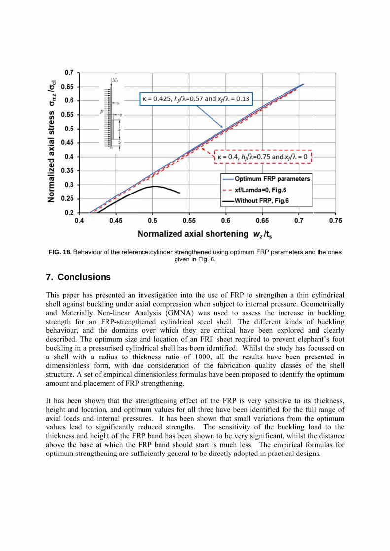
FIG. 18
7. Co This pashell agand Mastrengthbehaviodescribebucklinga shell dimensistructureamount It has bheight aaxial lovalues lthicknesabove thoptimum
. Behaviour o
nclusion
aper has pregainst buckliaterially Noh for an Four, and theed. The optg in a press
with a raionless forme. A set of eand placem
been shownand locationads and intlead to sigss and heighhe base at wm strengthen
of the referen
ns
esented an iing under axon-linear AFRP-strengthe domains timum size urised cylin
adius to thim, with duempirical di
ment of FRP
n that the stn, and optimternal pressugnificantly rht of the FRwhich the Fning are suf
nce cylinder
investigationxial compre
Analysis (GMhened cylin
over whicand locatio
ndrical shellickness rati
ue consideraimensionlesstrengtheni
trengtheningmum values ures. It hareduced streRP band hasFRP band sfficiently ge
strengthenedgiven in Fig.
n into the uession whenMNA) wasndrical steech they areon of an FRl has been idio of 1000ation of th
ss formulas hing.
g effect of for all thre
s been showengths. Ths been showshould start eneral to be d
d using optim6.
use of FRP n subject to s used to ael shell. The critical ha
RP sheet reqdentified. W
0, all the rhe fabricatiohave been p
the FRP isee have beenwn that smahe sensitivi
wn to be veris much le
directly ado
mum FRP par
to strengthinternal pre
assess the ihe differentave been e
quired to prWhilst the sresults haveon quality proposed to
s very sensin identifiedall variationity of the bry significaness. The emopted in prac
rameters and
hen a thin cessure. Geomincrease int kinds of explored anevent eleph
study has foe been preclasses of identify the
itive to its d for the fulns from thebuckling lont, whilst thmpirical forctical design
d the ones
cylindrical metrically
n buckling f buckling nd clearly hant’s foot ocussed on esented in
the shell e optimum
thickness, ll range of e optimum oad to the he distance rmulas for ns.
References ABAQUS/Standard User’s Manual, Version 6.12-1 (2012). ABAQUS Inc, USA. Batikha, M., Chen, J.F. and Rotter, J.M. (2007a) Numerical modelling of shells repaired using FRP. Proc., 3rd Int. Conf. on steel and composites structures, ICSCS07, 30July-1 August, Manchester, UK, 1065-1069. Batikha, M., Chen, J.F. and Rotter, J.M. (2007b) FRP strengthening of metallic cylindrical shells against elephant’s foot buckling. Proc., Conf. on Advanced composites in Construction, ACIC 07, 2-4 April, Bath, UK, 157-164. Batikha M., Chen J.F., Rotter J.M. and Teng J.G. (2009) Strengthening metallic cylindrical shells against elephant’s foot buckling with FRP. Thin-Walled Structures 47:1078–1091. Cao Q.S., Yang Zhao Y. and Zhang R. (2018) Wind induced buckling of large circular steel silos with various slenderness. Thin-Walled Structures 130:101–113. Chen, J. F., Rotter, J. M. and Teng, J.G. (2005) Strengthening silos and tanks against elephant’s foot buckling. Proc., 4th Int. Conf. on Advances in Steel Structures, ICASS 05, 13-15 June, Shanghai, China, 459-466 Chen, J. F., Rotter, J.M. and Teng, J.G. (2006) A simple remedy for elephant's foot buckling in cylindrical silos and tanks. Advances in Struct. Eng., 9(3):409-420. Djermane M., Zaoui D., Labbaci B. and Hammadi F. (2014) Dynamic buckling of steel tanks under seismic excitation: Numerical evaluation of code provisions. Engineering Structures 70:181–196. ECCS (2008) Buckling of steel shells - European design recommendations, the 5th Edition, European Convention for Constructional Steelwork. Brussels, Belgium. EN 1993-1-6 (2007) Eurocode 3: Design of steel structures—Part 1-6: Strength and stability of shell structures. Brussels: CEN. EN 1993-4-1 (2007) Eurocode 3 - Design of steel structures - Part 4-1: Silos. Brussels: CEN. EN 1998-4 (2006) Eurocode 8 - Design of structures for earthquake resistance - Part 4: Silos, tanks and pipelines. Brussels: CEN. Kildashti K., Mirzadeh N. and Samali B. (2018) Seismic vulnerability assessment of a case study anchored liquid storage tank by considering fixed and flexible base restraints. Thin-Walled Structures 123:382–394. Lu Y., Li N. and Li S. (2014) Behavior of FRP-Confined Concrete-Filled Steel Tube Columns. Polymers 6: 1333-1349.
NZS/BS 2654:1989 (1989) Specification for manufacture of vertical steel welded non-refrigerated storage tanks with butt-welded shells for the petroleum industry. Standards New Zealand, Wellington, New Zealand. Punitha Kumar A. and Senthil R. (2016 a) Axial Behaviour of CFRP-Strengthened Circular Steel Hollow Sections. Arab J Sci Eng 41:3841–3850. Punitha Kumar A. and Senthil R. (2016 b) Behavior of CFRP Strengthened CHS under Axial Static and Axial Cyclic Loading. KSCE Journal of Civil Engineering 20(4):1493-1500. Rotter, J.M. (1985a) Bending theory of shells for bins and silos. Design of Steel bins for the Storage of Bulk Solids, School of Civil and Mining Engineering, University of Sydney, pp 71-81. Rotter, J.M. (1985b) “Buckling of Ground-Supported Cylindrical Steel Bins under Vertical Compressive Wall Loads”, Proc., Metal Structures Conference, Institution of Engineers Australia, Melbourne, May 1985, pp 112-127. Rotter J.M. (1989) Stress amplification in unstiffened cylindrical steel silos and tanks. Institution of Engineers, Australia, Civil Engrg Transactions, CE31(3), 142-148. Rotter, J.M. (1990) Local collapse of axially compressed pressurized thin steel cylinders. J. Struct. Eng. 116(7):1955-1969. Rotter, J.M. (2004). Cylindrical shells under axial compression. In: Buckling of thin metal shells, J.G. Teng and J.M. Rotter, eds., Spon press, London, 42-87. Rotter J.M. (2006) Elephant’s Foot Buckling in Pressurized Cylindrical Shells. Stahlbau, 75 (9):742-747. Rotter, J.M. and Teng, J.G. (1989) Elastic stability of cylindrical shells with weld depressions. J. Struct. Eng. 115(5):1244-1263. Rotter, J.M. and Zhang, Q. (1990) Elastic buckling of imperfect cylinders containing granular solids. J. Struct. Eng. 116(8): 2253-2271. Riks, E. (1979) An incremental approach to the solution of snapping and buckling problems. Inter. J. of Solids and Structures 15(7):529-551. Sobhana M.S., F.R. Rofooeia F.R. and Attari N.K.A. (2017) Buckling behavior of the anchored steel tanks under horizontal and vertical ground motions using static pushover and incremental dynamic analyses. Thin-Walled Structures 112: 173–183. Teng, J.G., Chen, J.F., Smith, S.T. and Lam, L. (2002), FRP Strengthened RC Structures, John Wiley and Sons, Chichester, UK.
Teng, J.G. and Chen, J.F. (2009), “Mechanics of debonding in FRP-plated RC beams”, Proceedings of the Institution of Civil Engineers – Structures and Buildings, Vol. 162, No. SB5, pp335-345. Teng J.G., Yub T. and Fernando D. (2012) Strengthening of steel structures with fiber-reinforced polymer composites. Journal of Constructional Steel Research 78:131–143. Teng, J.G., Hu, Y.M. (2007). Behaviour of FRP-jacketed circular steel tubes and cylindrical shells under axial comparison. Construction and Building Materials, 21(4), 827-838. Teng, J.G. and Hu, Y.M. (2004) Suppression of local buckling in steel tubes by FRP jacketing. Proc., 2nd Int. Conf. on FRP Composites in Civil Engineering. Adelaide, Australia, 8-10 December, 749-753. Teng, G.J. and Rotter, J.M. (1992) Buckling of pressurized axisymmetrically imperfect cylinders under axial loads. J. Eng. Mech. 118(2): 229-247. Timoshenko S. and Woinowsky-Krieger S. (1959) Theory of Plates and Shells. Mcgraw-Hill,
New York. Zhao Y., Cao Q.S. and Su L. (2013) Buckling design of large circular steel silos subject to wind pressure. Thin-Walled Structures 73: 337–349. Zhu C.Y., YH Zhao Y.H. and Sun L. (2018) Seismic performance of FRP-reinforced concrete-filled thin-walled steel tube considering local buckling. Journal of Reinforced Plastics and Composites 37(9):592–608.