Embed Size (px)
Citation preview

FRONT AXLE &FRONT SUSPENSION
SECTIONFACONTENTS
PRECAUTIONS AND PREPARATION ............................2Supplemental Restraint System (SRS) ″AIRBAG″ and ″SEAT BELT PRE-TENSIONER″...............2Precautions for Brake System.....................................2Special Service Tools ..................................................3Commercial Service Tools ...........................................4
NOISE, VIBRATION AND HARSHNESS (NVH)TROUBLESHOOTING .....................................................5
NVH Troubleshooting Chart.........................................5FRONT SUSPENSION SYSTEM ....................................6ON-VEHICLE SERVICE ..................................................7
Front Axle and Front Suspension Parts ......................7Front Wheel Bearing....................................................8Front Wheel Alignment ................................................9
FRONT AXLE ................................................................13Wheel Hub and Knuckle............................................13ABS Sensor Rotor .....................................................16
FRONT SUSPENSION ..................................................17Coil Spring and Strut Assembly.................................18Tension Rod and Stabilizer Bar.................................22Transverse Link Assembly.........................................23
ACTIVE DAMPER SUSPENSION .................................24System Components .................................................24Component Description .............................................24Active Damper Suspension Configuration.................26Active Damper ...........................................................27Removal and Installation ...........................................28
TROUBLE DIAGNOSES ...............................................29How to Perform Trouble Diagnoses for Quickand Accurate Repair ..................................................29
Symptom Chart..........................................................30Fail-safe Remarks......................................................31Preliminary Check......................................................32Component Parts and Harness ConnectorLocations....................................................................33Schematic ..................................................................34Wiring Diagram..........................................................35Self-diagnoses ...........................................................40CONSULT-II Inspection Procedure............................42
TROUBLE DIAGNOSES FOR SELF-DIAGNOSTICITEMS.............................................................................48
Diagnostic Procedure 1 (Vehicle speed sensor) .......48Diagnostic Procedure 2 (Steering angle sensor) ......49Diagnostic Procedure 3 (Stop lamp switch) ..............50Diagnostic Procedure 4 (Vertical G sensor)..............51
TROUBLE DIAGNOSES FOR SYMPTOMS .................52Diagnostic Procedure 5 (SPORT indicator doesnot come on when ignition switch is turned on.).......52Diagnostic procedure 6 (Hard or soft feel)................54Diagnostic Procedure 7 (Heavy steeringoperation during stationary turns)..............................57Diagnostic Procedure 8 (Light steering duringhigh-speed operation)................................................58
TROUBLE DIAGNOSES FOR ACTIVE DAMPERSUSPENSION ................................................................59
Electrical Component Inspection ...............................59SERVICE DATA AND SPECIFICATIONS (SDS) ..........61
General Specifications...............................................61Inspection and Adjustment ........................................61
GI
MA
EM
LC
EC
FE
AT
PD
RA
BR
ST
RS
BT
HA
EL
IDX
EXITEXIT
Supplemental Restraint System (SRS) “AIRBAG” and “SEAT BELT PRE-TENSIONER”
The Supplemental Restraint System such as “AIR BAG” and “SEAT BELT PRE-TENSIONER” used along witha seat belt, helps to reduce the risk or severity of injury to the driver and front passenger for certain types ofcollision. The SRS system composition which is available to INFINITI Q45 is as follows:I For a frontal collision
The Supplemental Restraint System consists of driver air bag module (located in the center of the steer-ing wheel), front passenger air bag module (located on the instrument panel on passenger side), seat beltpre-tensioners, a diagnosis sensor unit, warning lamp, wiring harness and spiral cable.
I For a side collisionThe Supplemental Restraint System consists of front side air bag module (located in the outer side of frontseat), satellite sensor, diagnosis sensor unit (one of components of air bags for a frontal collision), wiringharness, warning lamp (one of components of air bags for a frontal collision).
Information necessary to service the system safely is included in the RS section of this Service Manual.WARNING:I To avoid rendering the SRS inoperative, which could increase the risk of personal injury or death
in the event of a collision which would result in air bag inflation, all maintenance should be per-formed by an authorized INFINITI dealer.
I Improper maintenance, including incorrect removal and installation of the SRS, can lead to per-sonal injury caused by intentional activation of the system. For removal of Spiral Cable and Air BagModule, see the RS section.
I Do not use electrical test equipment on any circuit related to the SRS unless instructed to in thisService Manual. Spiral cable and wiring harnesses covered with yellow insulation tape (exceptsatellite sensor and side air bag module) either just before the harness connectors or for the com-plete harness are related to the SRS.
SBR686C
Precautions for Brake SystemI When installing rubber parts, final tightening must be car-
ried out under unladen condition* with tires on ground.*: Fuel, radiator coolant and engine oil full. Spare tire,
jack, hand tools and mats in designated positions.I After installing removed suspension parts, check wheel
alignment and adjust if necessary.I Use flare nut wrench when removing or installing brake
tubes.I Always torque brake lines when installing.
PRECAUTIONS AND PREPARATION
FA-2
EXITEXIT
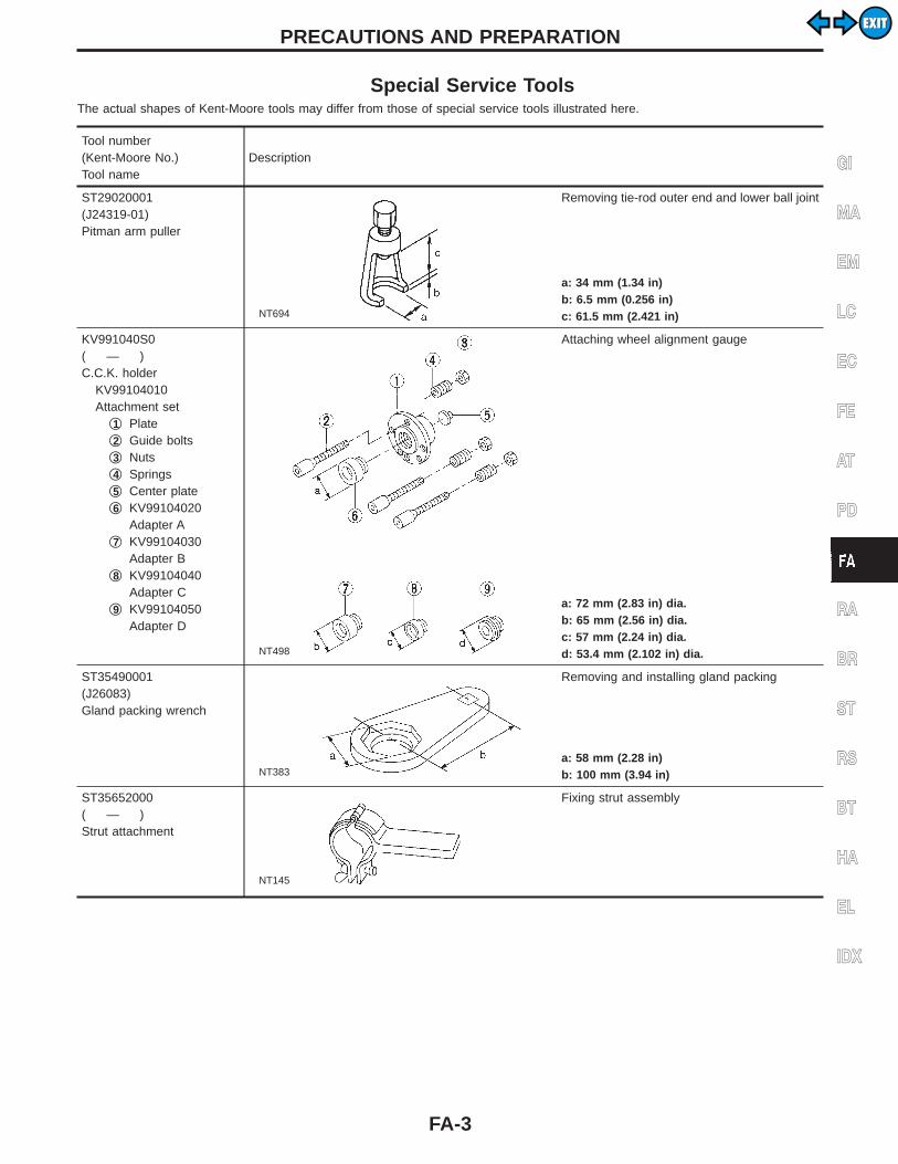
Special Service ToolsThe actual shapes of Kent-Moore tools may differ from those of special service tools illustrated here.
Tool number(Kent-Moore No.)Tool name
Description
ST29020001(J24319-01)Pitman arm puller
NT694
Removing tie-rod outer end and lower ball joint
a: 34 mm (1.34 in)b: 6.5 mm (0.256 in)c: 61.5 mm (2.421 in)
KV991040S0( — )C.C.K. holder
KV99104010Attachment set
q1 Plateq2 Guide boltsq3 Nutsq4 Springsq5 Center plateq6 KV99104020
Adapter Aq7 KV99104030
Adapter Bq8 KV99104040
Adapter Cq9 KV99104050
Adapter D
NT498
Attaching wheel alignment gauge
a: 72 mm (2.83 in) dia.b: 65 mm (2.56 in) dia.c: 57 mm (2.24 in) dia.d: 53.4 mm (2.102 in) dia.
ST35490001(J26083)Gland packing wrench
NT383
Removing and installing gland packing
a: 58 mm (2.28 in)b: 100 mm (3.94 in)
ST35652000( — )Strut attachment
NT145
Fixing strut assembly
GI
MA
EM
LC
EC
FE
AT
PD
RA
BR
ST
RS
BT
HA
EL
IDX
PRECAUTIONS AND PREPARATION
FA-3
EXITEXIT
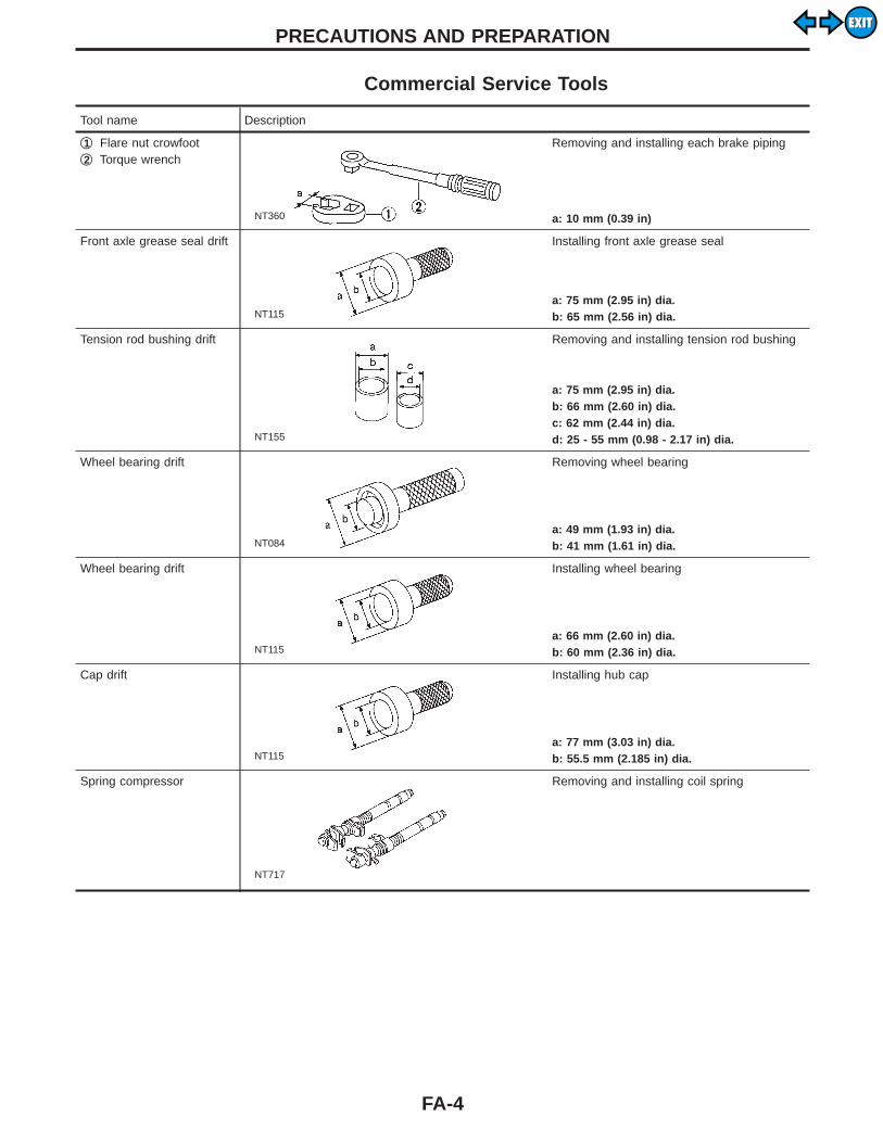
Commercial Service Tools
Tool name Description
q1 Flare nut crowfootq2 Torque wrench
NT360
Removing and installing each brake piping
a: 10 mm (0.39 in)
Front axle grease seal drift
NT115
Installing front axle grease seal
a: 75 mm (2.95 in) dia.b: 65 mm (2.56 in) dia.
Tension rod bushing drift
NT155
Removing and installing tension rod bushing
a: 75 mm (2.95 in) dia.b: 66 mm (2.60 in) dia.c: 62 mm (2.44 in) dia.d: 25 - 55 mm (0.98 - 2.17 in) dia.
Wheel bearing drift
NT084
Removing wheel bearing
a: 49 mm (1.93 in) dia.b: 41 mm (1.61 in) dia.
Wheel bearing drift
NT115
Installing wheel bearing
a: 66 mm (2.60 in) dia.b: 60 mm (2.36 in) dia.
Cap drift
NT115
Installing hub cap
a: 77 mm (3.03 in) dia.b: 55.5 mm (2.185 in) dia.
Spring compressor
NT717
Removing and installing coil spring
PRECAUTIONS AND PREPARATION
FA-4
EXITEXIT
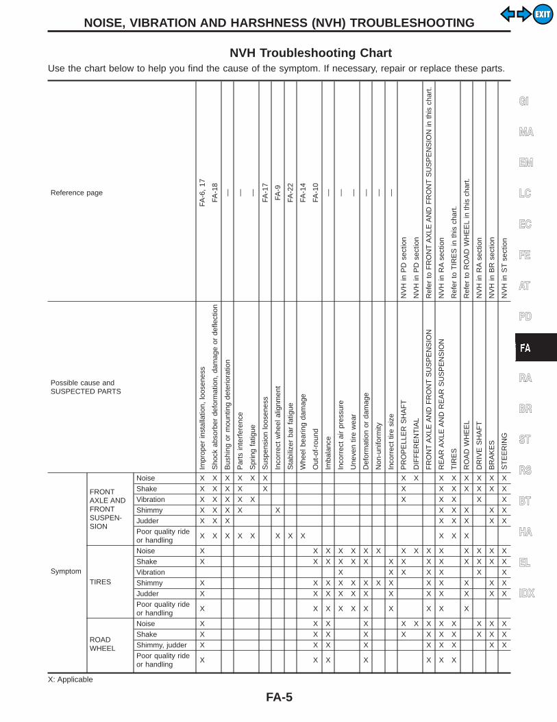
NVH Troubleshooting ChartUse the chart below to help you find the cause of the symptom. If necessary, repair or replace these parts.
Reference pageFA
-6,
17
FA-1
8
— — —
FA-1
7
FA-9
FA-2
2
FA-1
4
FA-1
0
— — — — — —
NV
Hin
PD
sect
ion
NV
Hin
PD
sect
ion
Ref
erto
FR
ON
TA
XLE
AN
DF
RO
NT
SU
SP
EN
SIO
Nin
this
char
t.
NV
Hin
RA
sect
ion
Ref
erto
TIR
ES
inth
isch
art.
Ref
erto
RO
AD
WH
EE
Lin
this
char
t.
NV
Hin
RA
sect
ion
NV
Hin
BR
sect
ion
NV
Hin
ST
sect
ion
Possible cause andSUSPECTED PARTS
Impr
oper
inst
alla
tion,
loos
enes
s
Sho
ckab
sorb
erde
form
atio
n,da
mag
eor
defle
ctio
n
Bus
hing
orm
ount
ing
dete
riora
tion
Par
tsin
terf
eren
ce
Spr
ing
fatig
ue
Sus
pens
ion
loos
enes
s
Inco
rrec
tw
heel
alig
nmen
t
Sta
biliz
erba
rfa
tigue
Whe
elbe
arin
gda
mag
e
Out
-of-
roun
d
Imba
lanc
e
Inco
rrec
tai
rpr
essu
re
Une
ven
tire
wea
r
Def
orm
atio
nor
dam
age
Non
-uni
form
ity
Inco
rrec
ttir
esi
ze
PR
OP
ELL
ER
SH
AF
T
DIF
FE
RE
NT
IAL
FR
ON
TA
XLE
AN
DF
RO
NT
SU
SP
EN
SIO
N
RE
AR
AX
LEA
ND
RE
AR
SU
SP
EN
SIO
N
TIR
ES
RO
AD
WH
EE
L
DR
IVE
SH
AF
T
BR
AK
ES
ST
EE
RIN
G
Symptom
FRONTAXLE ANDFRONTSUSPEN-SION
Noise X X X X X X X X X X X X X X
Shake X X X X X X X X X X X X
Vibration X X X X X X X X X X
Shimmy X X X X X X X X X X
Judder X X X X X X X X
Poor quality rideor handling
X X X X X X X X X X X
TIRES
Noise X X X X X X X X X X X X X X X
Shake X X X X X X X X X X X X X X
Vibration X X X X X X X
Shimmy X X X X X X X X X X X X X
Judder X X X X X X X X X X X X
Poor quality rideor handling
X X X X X X X X X X
ROADWHEEL
Noise X X X X X X X X X X X X
Shake X X X X X X X X X X X
Shimmy, judder X X X X X X X X X
Poor quality rideor handling
X X X X X X X
X: Applicable
GI
MA
EM
LC
EC
FE
AT
PD
RA
BR
ST
RS
BT
HA
EL
IDX
NOISE, VIBRATION AND HARSHNESS (NVH) TROUBLESHOOTING
FA-5
EXITEXIT
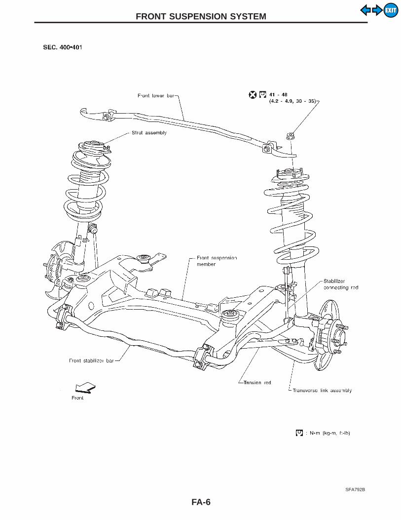
SFA792B
FRONT SUSPENSION SYSTEM
FA-6
EXITEXIT

SMA525A
Front Axle and Front Suspension PartsCheck front axle and front suspension parts for excessive play,cracks, wear or other damage.I Shake each front wheel to check for excessive play.
SFA741
I Make sure that cotter pin is inserted.I Retighten all nuts and bolts to the specified torque.
Tightening torque:Refer to FRONT SUSPENSION (FA-17).
SFA323B
SFA818A
I Check spring height from top of wheelarch to ground.a. Vehicle must be unladen*, parked on a level surface, and tires
checked for proper inflation and wear (tread wear indicatormust not be showing).*: Fuel, radiator coolant and engine oil full. Spare tire, jack,
hand tools and mats in designated positions.b. Bounce vehicle up and down several times before measuring.
Standard height: Refer to SDS (FA-62).c. Spring height is not adjustable. If out of specification, check for
worn springs or suspension parts.
SMA113
I Check strut (Shock absorber) for oil leakage or damage.
GI
MA
EM
LC
EC
FE
AT
PD
RA
BR
ST
RS
BT
HA
EL
IDX
ON-VEHICLE SERVICE
FA-7
EXITEXIT
SMA977A
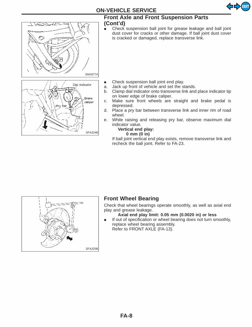
I Check suspension ball joint for grease leakage and ball jointdust cover for cracks or other damage. If ball joint dust coveris cracked or damaged, replace transverse link.
SFA324B
I Check suspension ball joint end play.a. Jack up front of vehicle and set the stands.b. Clamp dial indicator onto transverse link and place indicator tip
on lower edge of brake caliper.c. Make sure front wheels are straight and brake pedal is
depressed.d. Place a pry bar between transverse link and inner rim of road
wheel.e. While raising and releasing pry bar, observe maximum dial
indicator value.Vertical end play:
0 mm (0 in)If ball joint vertical end play exists, remove transverse link andrecheck the ball joint. Refer to FA-23.
SFA325B
Front Wheel BearingCheck that wheel bearings operate smoothly, as well as axial endplay and grease leakage.
Axial end play limit: 0.05 mm (0.0020 in) or lessI If out of specification or wheel bearing does not turn smoothly,
replace wheel bearing assembly.Refer to FRONT AXLE (FA-13).
ON-VEHICLE SERVICEFront Axle and Front Suspension Parts(Cont’d)
FA-8
EXITEXIT

Front Wheel AlignmentCAMBER, CASTER AND KINGPIN INCLINATIONCamber, caster and kingpin inclination are preset at factoryand cannot be adjusted.1. Set vehicle on turning radius gauge.
SFA637B
2. Mount Tool as follows.Tool number:
KV991040S0 ( — )KV99104010 q1 to q5KV99104020 q6KV99104030 q7KV99104040 q8KV99104050 q9
a. Select adapter which corresponds with wheel or hub shapefrom four types q6 to q9 .
b. Screw selected adapter in until it contacts plate q1 .
SFA893A
c. Remove wheel nuts.
SFA894AA
d. Install guide bolts q2 to where wheel nuts were removed andtighten them by hand.
e. Install plate and adapter assembly to guide bolts q2 .f. Install springs q4 onto guide bolts q2 . Then tighten nuts
q3 evenly until a little before springs q4 are completely com-pressed.
g. Install center plate q5 .h. Mount wheel alignment gauge on attachment plate.
GI
MA
EM
LC
EC
FE
AT
PD
RA
BR
ST
RS
BT
HA
EL
IDX
ON-VEHICLE SERVICE
FA-9
EXITEXIT

Before checking front wheel alignment, be sure to make a prelimi-nary inspection (Unladen*).*: Fuel, radiator coolant and engine oil full. Spare tire, jack, hand
tools and mats in designated positions.
SFA975B
PRELIMINARY INSPECTION
Aluminum wheel1. Check tires for wear and improper inflation.2. Check wheels for deformation, cracks and other damage. If
deformed, remove wheel and check wheel runout.a. Remove tire from aluminum wheel and mount on a tire balance
machine.b. Set dial indicator as shown in the illustration.
Wheel runout (Dial indicator value):Refer to SDS.
3. Check front wheel bearings for looseness.4. Check front suspension for looseness.5. Check steering linkage for looseness.6. Check that front shock absorbers work properly.7. Check vehicle posture (Unladen).
SFA981B
Steel wheel1. Check tires for wear and improper inflation.2. Check wheels for deformation, cracks and other damage.
If deformed, remove wheel and check wheel runout.a. Remove tire from steel wheel and mount wheel on a tire bal-
ance machine.b. Set two dial indicators as shown in the illustration.c. Set each dial indicator to 0.d. Rotate wheel and check dial indicators at several points
around the circumference of the wheel.e. Calculate runout at each point as shown below.
Radial runout = (A + B)/2Lateral runout = (C + D)/2
f. Select maximum positive runout value and the maximumnegative value.Add the two values to determine total runout.In case a positive or negative value is not available, use themaximum value (negative or positive) for total runout.If the total runout value exceeds the limit, replace steel wheel.
Wheel runout:Refer to SDS.
3. Check front wheel bearings for looseness.4. Check front suspension for looseness.5. Check steering linkage for looseness.
ON-VEHICLE SERVICEFront Wheel Alignment (Cont’d)
FA-10
EXITEXIT

6. Check that front shock absorbers work properly.7. Check vehicle posture (Unladen).
SFA326BA
CAMBER, CASTER AND KINGPIN INCLINATIONCamber, caster and kingpin inclination are preset at factoryand cannot be adjusted.1. Measure camber, caster and kingpin inclination of both right
and left wheels with a suitable alignment gauge.Camber, Caster and Kingpin inclination:
Refer to SDS (FA-61).2. If camber, caster and kingpin inclination are not within
specification, inspect and replace any damaged or worn frontsuspension parts.
SFA614B
SFA234AC
TOE-INMeasure toe-in using following procedure. If out of specification,inspect and replace any damaged or worn front suspension parts.WARNING:I Always perform the following procedure on a flat surface.I Make sure that no person is in front of the vehicle before
pushing it.1. Bounce front of vehicle up and down to stabilize the posture.2. Push the vehicle straight ahead about 5 m (16 ft).3. Put a mark on base line of tread (rear side) of both tires at the
same height as hub center. These are measuring points.4. Measure distance “A” (rear side).5. Push the vehicle slowly ahead to rotate the wheels 180
degrees (1/2 turn).If the wheels have rotated more than 180 degrees (1/2 turn), trythe above procedure again from the beginning. Never pushvehicle backward.6. Measure distance “B” (front side).
Total toe-in: Refer to SDS (FA-61).
SMA727A
7. Adjust toe-in by varying the length of steering tie-rods.a. Loosen lock nuts.
GI
MA
EM
LC
EC
FE
AT
PD
RA
BR
ST
RS
BT
HA
EL
IDX
ON-VEHICLE SERVICEFront Wheel Alignment (Cont’d)
FA-11
EXITEXIT
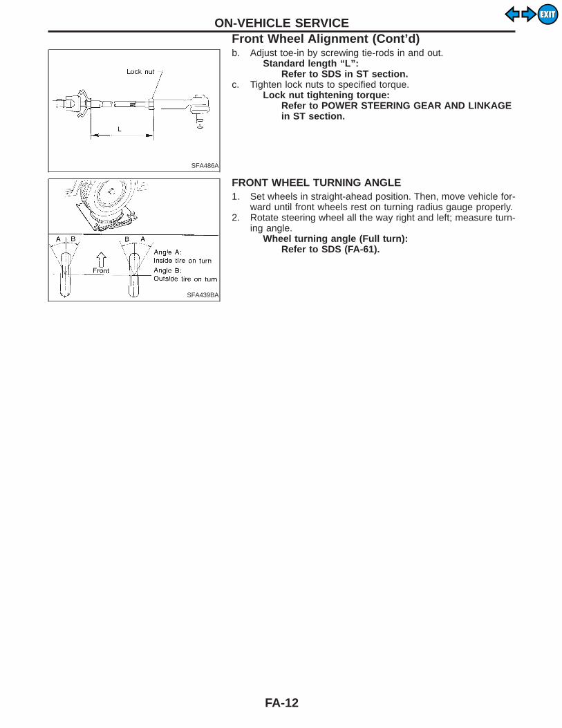
SFA486A
b. Adjust toe-in by screwing tie-rods in and out.Standard length “L”:
Refer to SDS in ST section.c. Tighten lock nuts to specified torque.
Lock nut tightening torque:Refer to POWER STEERING GEAR AND LINKAGEin ST section.
SFA439BA
FRONT WHEEL TURNING ANGLE1. Set wheels in straight-ahead position. Then, move vehicle for-
ward until front wheels rest on turning radius gauge properly.2. Rotate steering wheel all the way right and left; measure turn-
ing angle.Wheel turning angle (Full turn):
Refer to SDS (FA-61).
ON-VEHICLE SERVICEFront Wheel Alignment (Cont’d)
FA-12
EXITEXIT

SFA562BB
SFA328B
Wheel Hub and KnuckleREMOVALI Remove brake caliper assembly and rotor.CAUTION:I Brake hose need not be disconnected from brake caliper.
Be careful not to depress brake pedal, or piston will popout. Do not pull or twist brake hose.
I Before removing the front axle assembly, disconnect theABS wheel sensor from the assembly. Then, move it awayfrom the front axle assembly area. Failure to do so mayresult in damaging the sensor wires and the sensor willbecome inoperative.
GI
MA
EM
LC
EC
FE
AT
PD
RA
BR
ST
RS
BT
HA
EL
IDX
FRONT AXLE
FA-13
EXITEXIT

SFA329B
I Remove wheel hub from spindle.
SFA331B
I Remove grease seal.I Remove snap ring.
SFA330B
I Press out bearing and race as a set.
INSPECTION
Wheel bearingCheck wheel bearing to see that it rolls freely and is free fromnoise, crack, pitting, or wear, and replace if damaged.
Wheel hubCheck wheel hub for crack by a magnetic exploration or dyeingtest, and replace if cracked.
Knuckle spindleCheck knuckle spindle for deformation, tapping mark, or cracks (bymagnetic or dyeing test) and replace if damaged.
FRONT AXLEWheel Hub and Knuckle (Cont’d)
FA-14
EXITEXIT
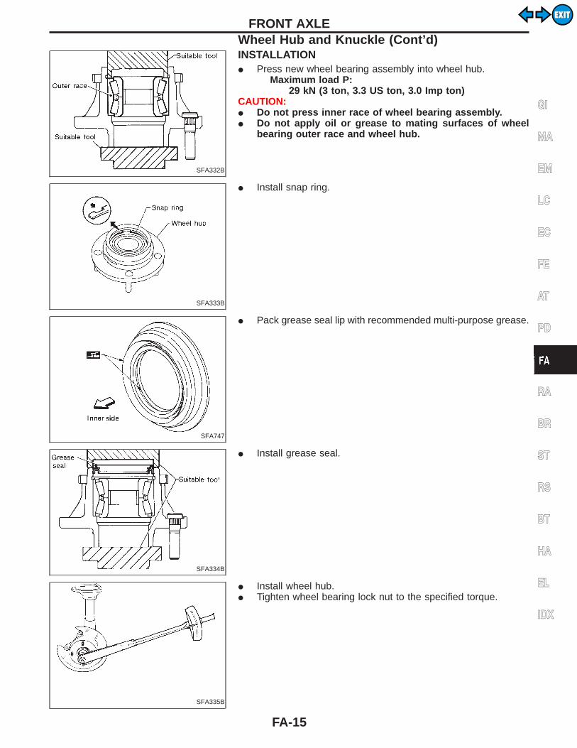
SFA332B
INSTALLATIONI Press new wheel bearing assembly into wheel hub.
Maximum load P:29 kN (3 ton, 3.3 US ton, 3.0 Imp ton)
CAUTION:I Do not press inner race of wheel bearing assembly.I Do not apply oil or grease to mating surfaces of wheel
bearing outer race and wheel hub.
SFA333B
I Install snap ring.
SFA747
I Pack grease seal lip with recommended multi-purpose grease.
SFA334B
I Install grease seal.
SFA335B
I Install wheel hub.I Tighten wheel bearing lock nut to the specified torque.
GI
MA
EM
LC
EC
FE
AT
PD
RA
BR
ST
RS
BT
HA
EL
IDX
FRONT AXLEWheel Hub and Knuckle (Cont’d)
FA-15
EXITEXIT
SFA336B
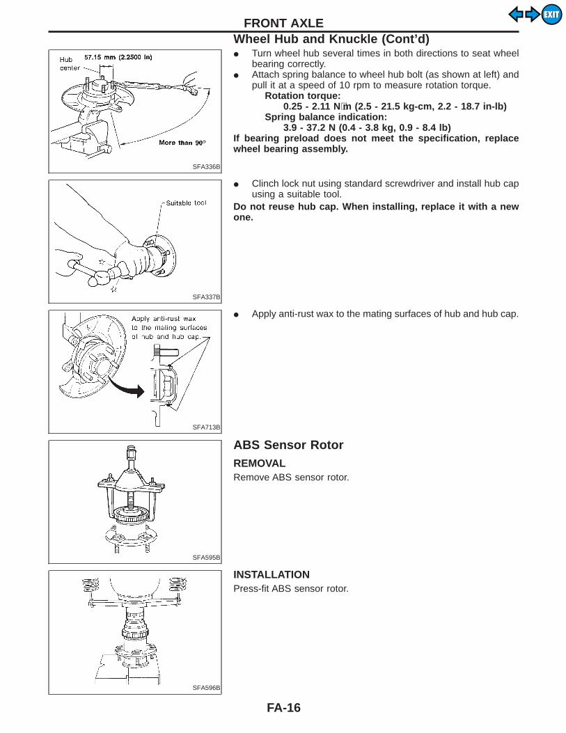
I Turn wheel hub several times in both directions to seat wheelbearing correctly.
I Attach spring balance to wheel hub bolt (as shown at left) andpull it at a speed of 10 rpm to measure rotation torque.
Rotation torque:0.25 - 2.11 N⋅m (2.5 - 21.5 kg-cm, 2.2 - 18.7 in-lb)
Spring balance indication:3.9 - 37.2 N (0.4 - 3.8 kg, 0.9 - 8.4 lb)
If bearing preload does not meet the specification, replacewheel bearing assembly.
SFA337B
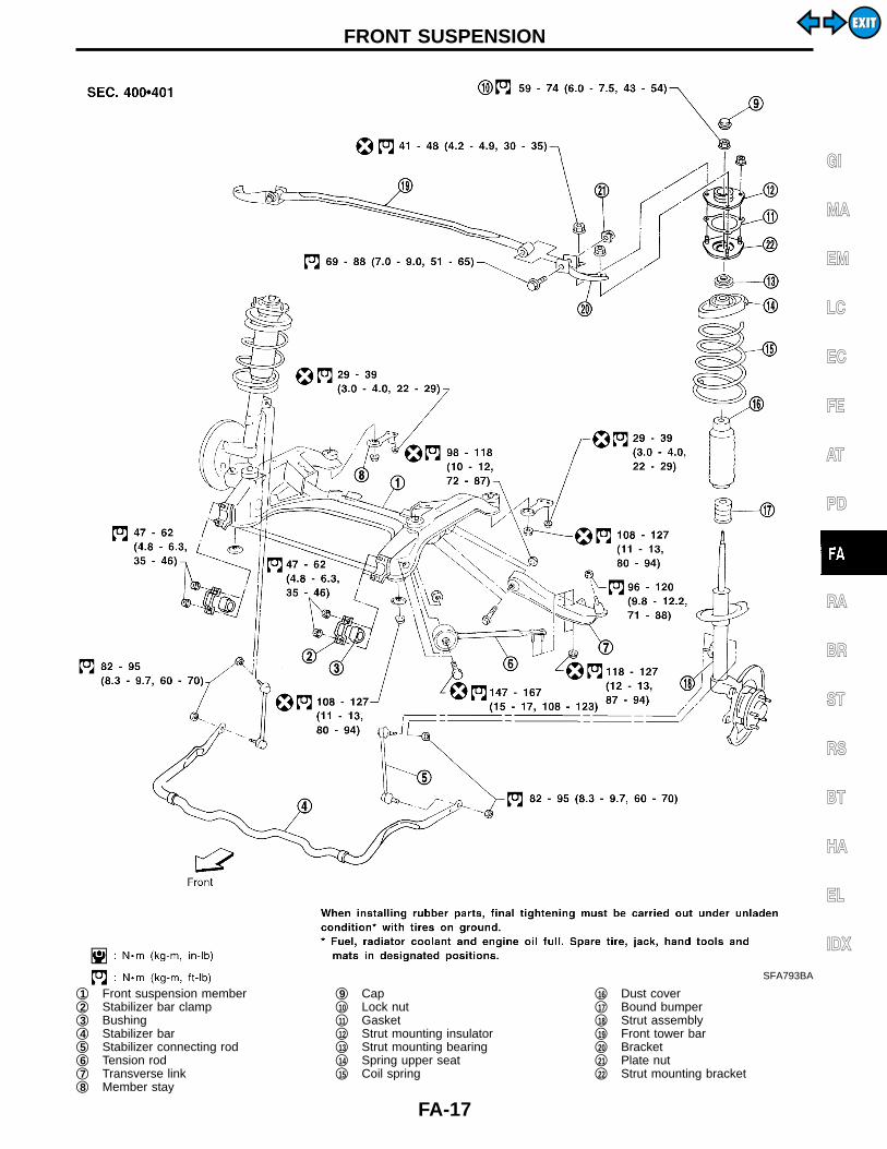
I Clinch lock nut using standard screwdriver and install hub capusing a suitable tool.
Do not reuse hub cap. When installing, replace it with a newone.
SFA713B
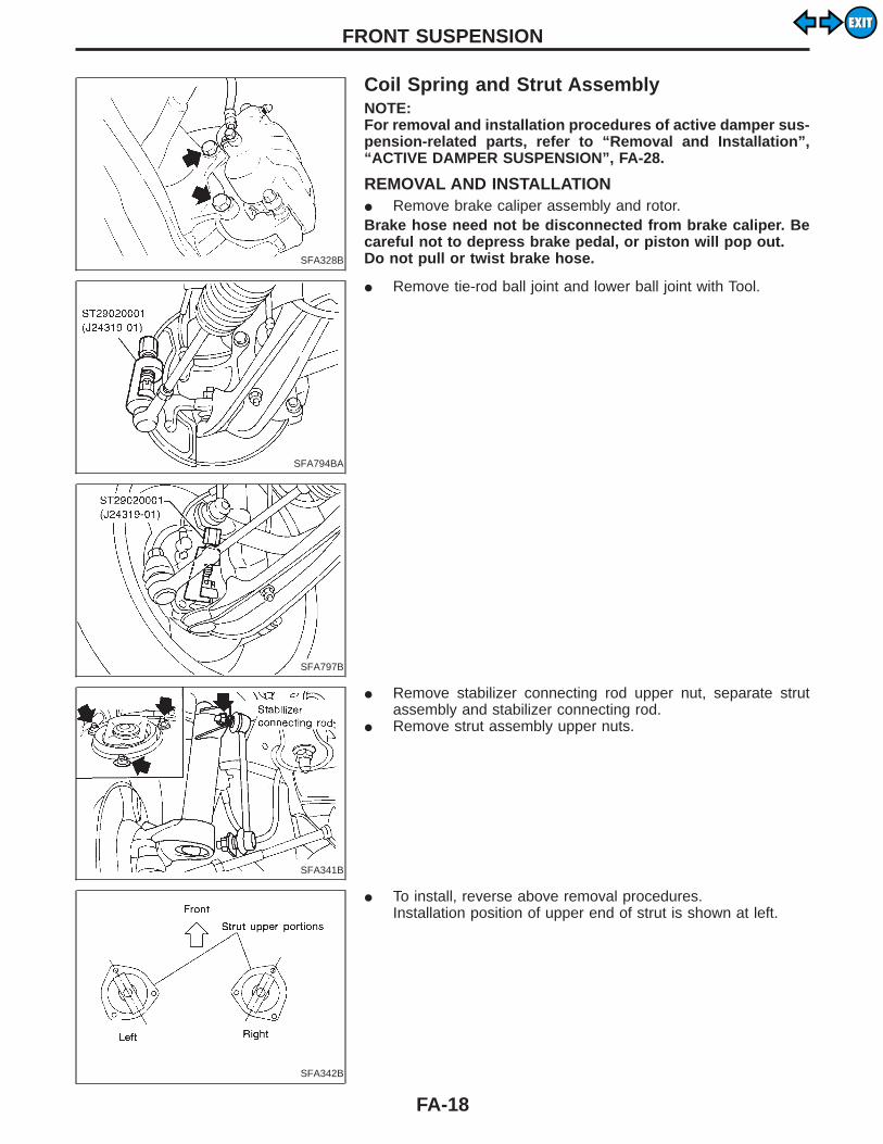
I Apply anti-rust wax to the mating surfaces of hub and hub cap.
SFA595B
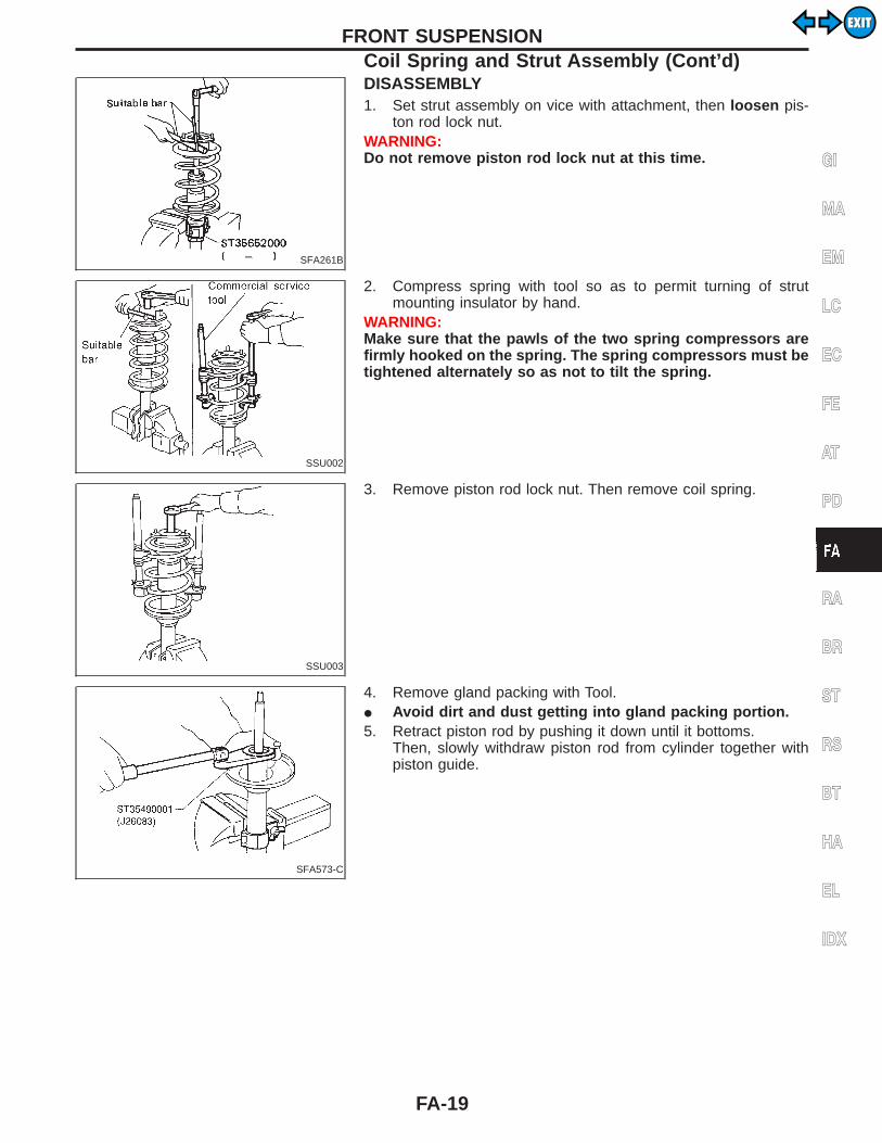
ABS Sensor RotorREMOVALRemove ABS sensor rotor.
SFA596B
INSTALLATIONPress-fit ABS sensor rotor.
FRONT AXLEWheel Hub and Knuckle (Cont’d)
FA-16
EXITEXIT
SFA793BA
q1 Front suspension memberq2 Stabilizer bar clampq3 Bushingq4 Stabilizer barq5 Stabilizer connecting rodq6 Tension rodq7 Transverse linkq8 Member stay
q9 Capq10 Lock nutq11 Gasketq12 Strut mounting insulatorq13 Strut mounting bearingq14 Spring upper seatq15 Coil spring
q16 Dust coverq17 Bound bumperq18 Strut assemblyq19 Front tower barq20 Bracketq21 Plate nutq22 Strut mounting bracket
GI
MA
EM
LC
EC
FE
AT
PD
RA
BR
ST
RS
BT
HA
EL
IDX
FRONT SUSPENSION
FA-17
EXITEXIT
SFA328B
Coil Spring and Strut AssemblyNOTE:For removal and installation procedures of active damper sus-pension-related parts, refer to “Removal and Installation”,“ACTIVE DAMPER SUSPENSION”, FA-28.
REMOVAL AND INSTALLATIONI Remove brake caliper assembly and rotor.Brake hose need not be disconnected from brake caliper. Becareful not to depress brake pedal, or piston will pop out.Do not pull or twist brake hose.
SFA794BA
I Remove tie-rod ball joint and lower ball joint with Tool.
SFA797B
SFA341B
I Remove stabilizer connecting rod upper nut, separate strutassembly and stabilizer connecting rod.
I Remove strut assembly upper nuts.
SFA342B
I To install, reverse above removal procedures.Installation position of upper end of strut is shown at left.
FRONT SUSPENSION
FA-18
EXITEXIT
SFA261B
DISASSEMBLY1. Set strut assembly on vice with attachment, then loosen pis-
ton rod lock nut.WARNING:Do not remove piston rod lock nut at this time.
SSU002
2. Compress spring with tool so as to permit turning of strutmounting insulator by hand.
WARNING:Make sure that the pawls of the two spring compressors arefirmly hooked on the spring. The spring compressors must betightened alternately so as not to tilt the spring.
SSU003
3. Remove piston rod lock nut. Then remove coil spring.
SFA573-C
4. Remove gland packing with Tool.I Avoid dirt and dust getting into gland packing portion.5. Retract piston rod by pushing it down until it bottoms.
Then, slowly withdraw piston rod from cylinder together withpiston guide.
GI
MA
EM
LC
EC
FE
AT
PD
RA
BR
ST
RS
BT
HA
EL
IDX
FRONT SUSPENSIONCoil Spring and Strut Assembly (Cont’d)
FA-19
EXITEXIT

INSPECTIONWash all parts, except for nonmetallic parts, clean with suitablesolvent and dry with compressed air.Blow dirt and dust off of nonmetallic parts using compressed air.
Strut assemblyI Oil oozing out around gland packing does not need strut
replacement.If oil leakage is evident on spring seat, check piston rod glandpacking and O-ring.If oil leakage occurs on welded portion of outer strut casing,replace strut assembly.
I If shock absorber itself is malfunctioning, replace as shockabsorber kit.
Gland packingCheck gland packing for oil leakage. Replace gland packing ifnecessary.
Strut mounting insulatorCheck cemented rubber-to-metal portion for melting or cracks.Check rubber parts for deterioration. Replace if necessary.
Thrust seatCheck for cracks, deformation or other damage. Replace if neces-sary.
Coil springCheck for cracks, deformation or other damage. Replace if neces-sary.
SFA141
ASSEMBLYI Lubricate sealing lip of gland packing.
SFA574
I Install gland packing.Cover piston rod with tape so as not to damage oil sealing lip.
FRONT SUSPENSIONCoil Spring and Strut Assembly (Cont’d)
FA-20
EXITEXIT

SFA759-C
I Tighten gland packing to the specified torque (refer to chart atleft) with Tool.
SFA760
I When installing coil spring, be careful not to reverse top andbottom direction. (Top end is flat.)
SFA664A
I Install upper spring seat with its cutout facing the outer side ofvehicle.
GI
MA
EM
LC
EC
FE
AT
PD
RA
BR
ST
RS
BT
HA
EL
IDX
FRONT SUSPENSIONCoil Spring and Strut Assembly (Cont’d)
FA-21
EXITEXIT
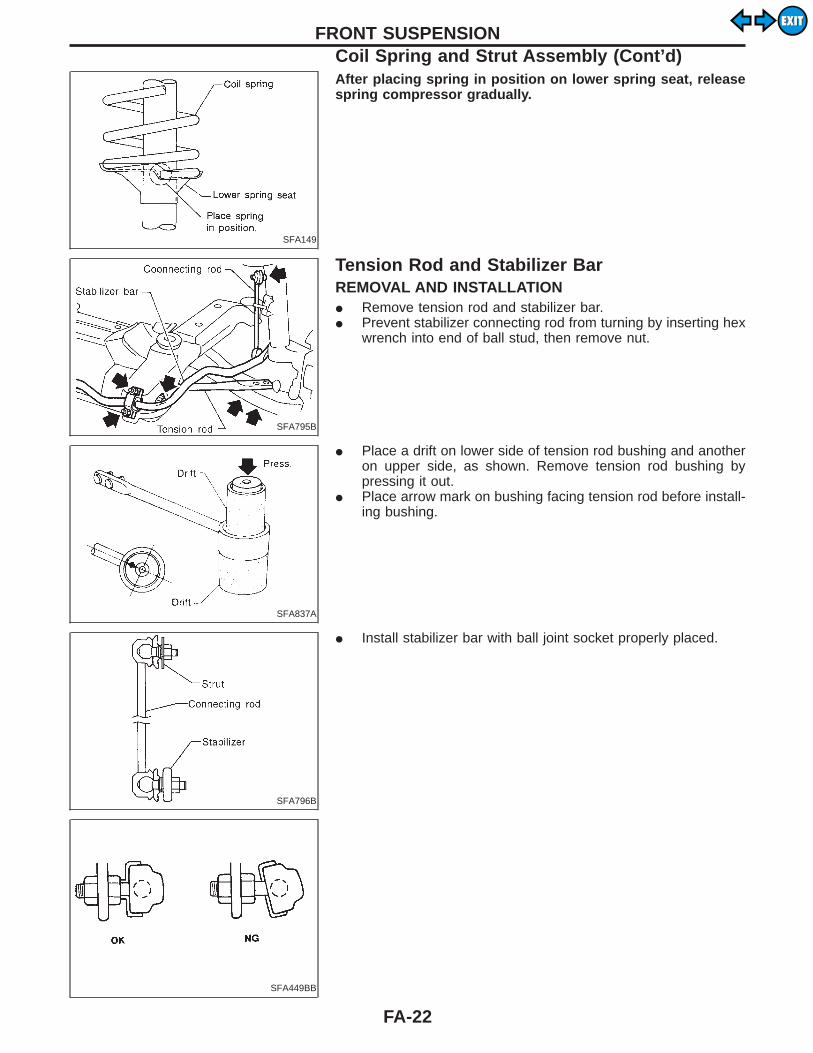
SFA149
After placing spring in position on lower spring seat, releasespring compressor gradually.
SFA795B
Tension Rod and Stabilizer BarREMOVAL AND INSTALLATIONI Remove tension rod and stabilizer bar.I Prevent stabilizer connecting rod from turning by inserting hex
wrench into end of ball stud, then remove nut.
SFA837A
I Place a drift on lower side of tension rod bushing and anotheron upper side, as shown. Remove tension rod bushing bypressing it out.
I Place arrow mark on bushing facing tension rod before install-ing bushing.
SFA796B
I Install stabilizer bar with ball joint socket properly placed.
SFA449BB
FRONT SUSPENSIONCoil Spring and Strut Assembly (Cont’d)
FA-22
EXITEXIT

SFA344B
Transverse Link AssemblyREMOVAL AND INSTALLATIONI Separate suspension ball joint from knuckle arm.I Remove tension rod and transverse link assembly.
SFA858A
INSPECTIONI Check tension rod, stabilizer bar and transverse link for
damage, cracks, deformation; replace transverse link assem-bly if necessary.
I Check rubber bushing for damage, cracks and deformation;replace tension rod or transverse link assembly if necessary.
I Check ball joint for excessive play. Replace transverse linkassembly if any of the following exists:I Ball stud is worn.I Joint is hard to swing.I Play in axial direction is excessive.Before checking, turn ball joint at least 10 revolutions so thatball joint is properly broken in.
Swinging force:Refer to SDS (FA-62).
Turning torque:Refer to SDS (FA-62).
Vertical end play:Refer to SDS (FA-62).
I Check dust cover for damage. Replace it and cover clamp ifnecessary.
GI
MA
EM
LC
EC
FE
AT
PD
RA
BR
ST
RS
BT
HA
EL
IDX
FRONT SUSPENSION
FA-23
EXITEXIT
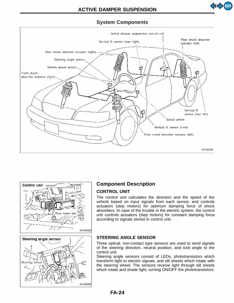
System Components
SFA926B
SFA993B
Component DescriptionCONTROL UNITThe control unit calculates the direction and the speed of thevehicle based on input signals from each sensor, and controlsactuators (step motors) for optimum damping force of shockabsorbers. In case of the trouble in the electric system, the controlunit controls actuators (step motors) for constant damping forceaccording to signals stored in control unit.
SFA994B
STEERING ANGLE SENSORThree optical, non-contact type sensors are used to send signalsof the steering direction, neutral position, and lock angle to thecontrol unit.Steering angle sensors consist of LEDs, phototransistors whichtransform light to electric signals, and slit sheets which rotate withthe steering wheel. The sensors receive light through slit sheetswhich rotate and shade light, turning ON/OFF the phototransistors.
ACTIVE DAMPER SUSPENSION
FA-24
EXITEXIT
SFA995B
SFA996B
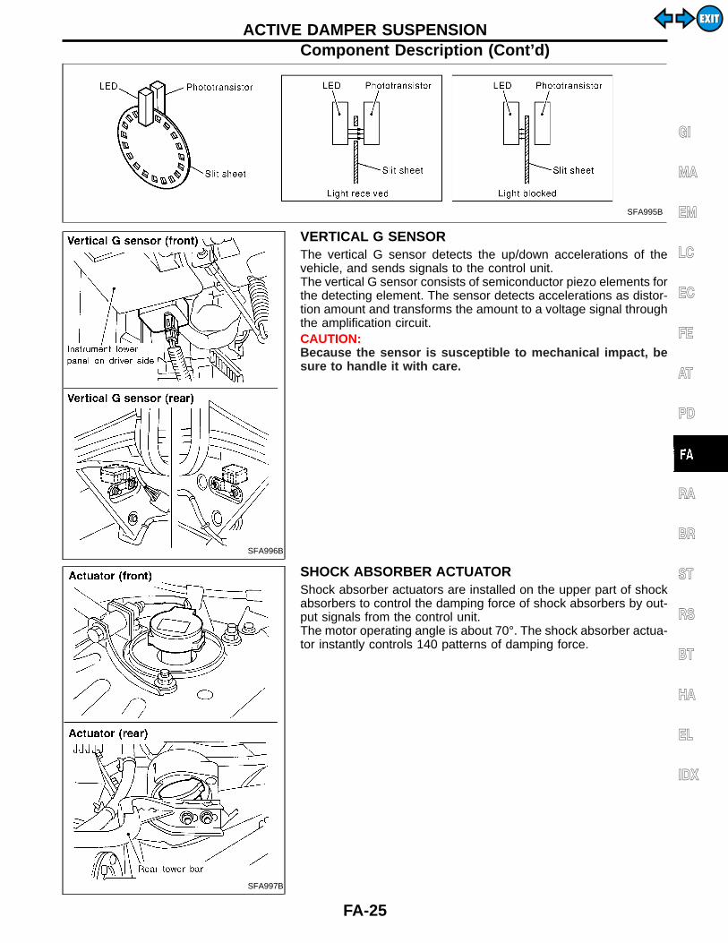
VERTICAL G SENSORThe vertical G sensor detects the up/down accelerations of thevehicle, and sends signals to the control unit.The vertical G sensor consists of semiconductor piezo elements forthe detecting element. The sensor detects accelerations as distor-tion amount and transforms the amount to a voltage signal throughthe amplification circuit.CAUTION:Because the sensor is susceptible to mechanical impact, besure to handle it with care.
SFA997B
SHOCK ABSORBER ACTUATORShock absorber actuators are installed on the upper part of shockabsorbers to control the damping force of shock absorbers by out-put signals from the control unit.The motor operating angle is about 70°. The shock absorber actua-tor instantly controls 140 patterns of damping force.
GI
MA
EM
LC
EC
FE
AT
PD
RA
BR
ST
RS
BT
HA
EL
IDX
ACTIVE DAMPER SUSPENSIONComponent Description (Cont’d)
FA-25
EXITEXIT

Active Damper Suspension Configuration
SFA658B
ACTIVE DAMPER SUSPENSION
FA-26
EXITEXIT

Active Damper
SFA972B
GI
MA
EM
LC
EC
FE
AT
PD
RA
BR
ST
RS
BT
HA
EL
IDX
ACTIVE DAMPER SUSPENSION
FA-27
EXITEXIT
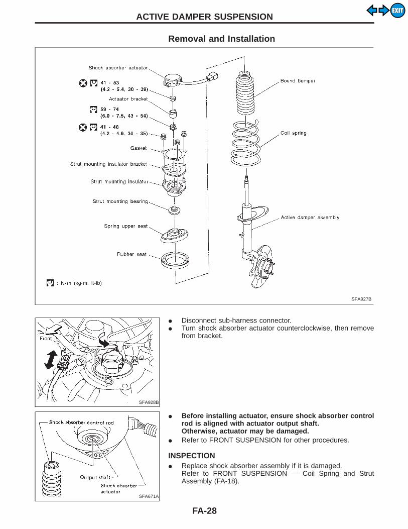
Removal and Installation
SFA927B
SFA928B
I Disconnect sub-harness connector.I Turn shock absorber actuator counterclockwise, then remove
from bracket.
SFA671A
I Before installing actuator, ensure shock absorber controlrod is aligned with actuator output shaft.Otherwise, actuator may be damaged.
I Refer to FRONT SUSPENSION for other procedures.
INSPECTIONI Replace shock absorber assembly if it is damaged.
Refer to FRONT SUSPENSION — Coil Spring and StrutAssembly (FA-18).
ACTIVE DAMPER SUSPENSION
FA-28
EXITEXIT

How to Perform Trouble Diagnoses for Quickand Accurate RepairINTRODUCTIONI Before troubleshooting, verify customer complaints concerning
his vehicle.I If a vehicle problem is hard to reproduce, harnesses, harness
connectors and/or terminals may often be faulty. Hold andshake these parts by hand to make sure they are securelyconnected.
I When using a circuit tester to measure voltage or resistanceof each circuit, be careful not to expand connector terminalsunnecessarily.
WORK FLOW
INSPECTION START Reference item
Verify customer complaints.
Determine related reference item concerning symptom.
Preliminary inspectionF
Preliminary check (Refer to FA-32.)
E Perform self-diagnosis.F
Self-diagnosis (Refer to FA-40.)
Check symptom.F
TROUBLE DIAGNOSES FOR SYMPTOMS (Refer toFA-52.)
Repair or replace faulty parts.
Perform self-diagnosis. Prior to final checks, turn ignition switch to “OFF” , “ON” fol-lowing the self-diagnosis to initialize actuator positioning.
NG
Final check
OK
END
GI
MA
EM
LC
EC
FE
AT
PD
RA
BR
ST
RS
BT
HA
EL
IDX
TROUBLE DIAGNOSES
H
H
H
H
H
H
H
H
H
FA-29
EXITEXIT
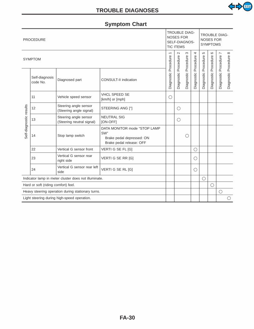
Symptom Chart
PROCEDURE
TROUBLE DIAG-NOSES FORSELF-DIAGNOS-TIC ITEMS
TROUBLE DIAG-NOSES FORSYMPTOMS
SYMPTOM
Dia
gnos
ticP
roce
dure
1
Dia
gnos
ticP
roce
dure
2
Dia
gnos
ticP
roce
dure
3
Dia
gnos
ticP
roce
dure
4
Dia
gnos
ticP
roce
dure
5
Dia
gnos
ticP
roce
dure
6
Dia
gnos
ticP
roce
dure
7
Dia
gnos
ticP
roce
dure
8
Sel
f-di
agno
stic
resu
lts
Self-diagnosiscode No.
Diagnosed part CONSULT-II indication
11 Vehicle speed sensorVHCL SPEED SE[km/h] or [mph]
q
12Steering angle sensor(Steering angle signal)
STEERING ANG [°] q
13Steering angle sensor(Steering neutral signal)
NEUTRAL SIG[ON-OFF]
q
14 Stop lamp switch
DATA MONITOR mode “STOP LAMPSW”
Brake pedal depressed: ONBrake pedal release: OFF
q
22 Vertical G sensor front VERTI G SE FL [G] q
23Vertical G sensor rearright side
VERTI G SE RR [G] q
24Vertical G sensor rear leftside
VERTI G SE RL [G] q
Indicator lamp in meter cluster does not illuminate. q
Hard or soft (riding comfort) feel. q
Heavy steering operation during stationary turns. q
Light steering during high-speed operation. q
TROUBLE DIAGNOSES
FA-30
EXITEXIT
Fail-safe RemarksFAIL-SAFE FUNCTION (Active damper suspension)The active damper suspension electronically controls the shockabsorber dampening force. If, for some reason, the dampeningforce falls under any of the conditions listed in the “Fail-safe items”table below, the fail-safe system will activate to maintain a constantlevel of shock absorber dampening force. If symptoms (such asunstable steering, unpleasant riding comfort, etc.) are pointed out,check and correct the faulty part or area using the diagnostic pro-cedure outlined under “Diagnostic Procedure 6 (Hard or soft feel)”.Refer to FA-54.
SFA662B
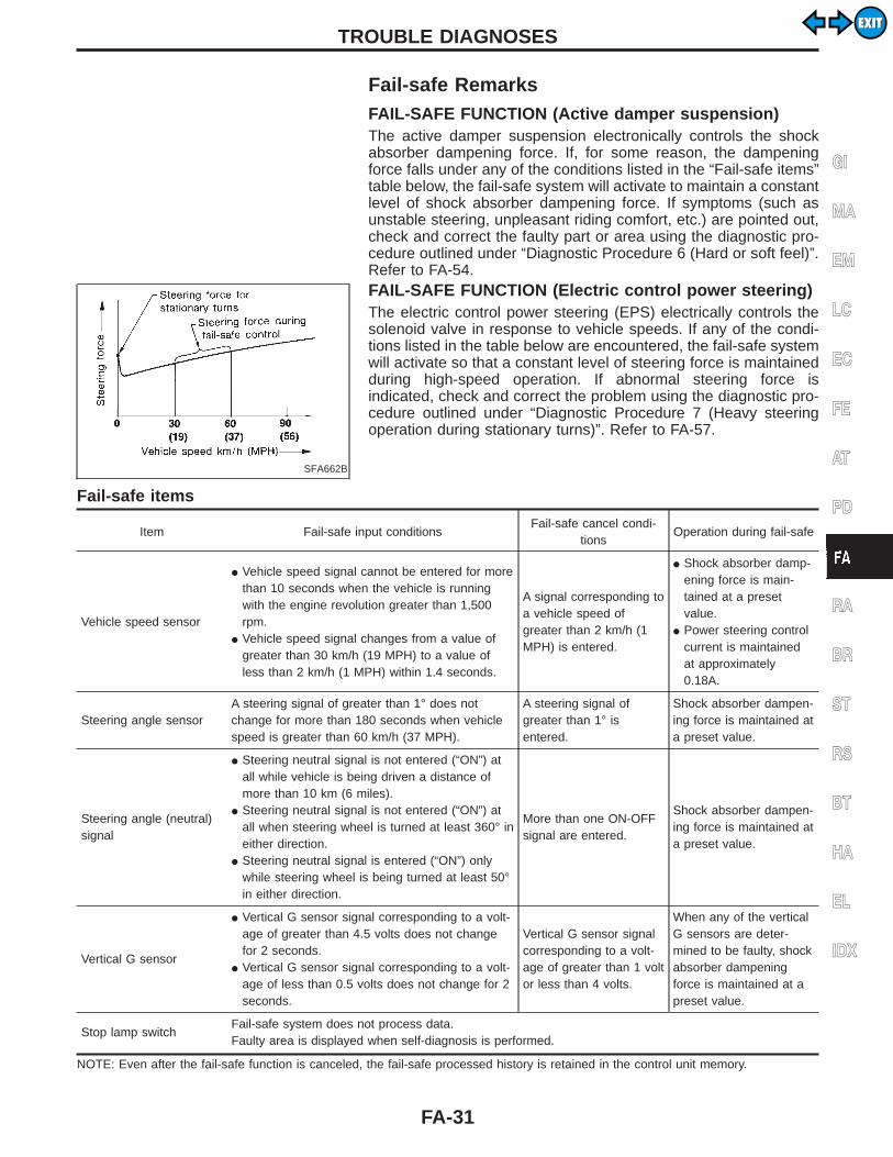
FAIL-SAFE FUNCTION (Electric control power steering)The electric control power steering (EPS) electrically controls thesolenoid valve in response to vehicle speeds. If any of the condi-tions listed in the table below are encountered, the fail-safe systemwill activate so that a constant level of steering force is maintainedduring high-speed operation. If abnormal steering force isindicated, check and correct the problem using the diagnostic pro-cedure outlined under “Diagnostic Procedure 7 (Heavy steeringoperation during stationary turns)”. Refer to FA-57.
Fail-safe items
Item Fail-safe input conditionsFail-safe cancel condi-
tionsOperation during fail-safe
Vehicle speed sensor
I Vehicle speed signal cannot be entered for morethan 10 seconds when the vehicle is runningwith the engine revolution greater than 1,500rpm.
I Vehicle speed signal changes from a value ofgreater than 30 km/h (19 MPH) to a value ofless than 2 km/h (1 MPH) within 1.4 seconds.
A signal corresponding toa vehicle speed ofgreater than 2 km/h (1MPH) is entered.
I Shock absorber damp-ening force is main-tained at a presetvalue.
I Power steering controlcurrent is maintainedat approximately0.18A.
Steering angle sensorA steering signal of greater than 1° does notchange for more than 180 seconds when vehiclespeed is greater than 60 km/h (37 MPH).
A steering signal ofgreater than 1° isentered.
Shock absorber dampen-ing force is maintained ata preset value.
Steering angle (neutral)signal
I Steering neutral signal is not entered (“ON”) atall while vehicle is being driven a distance ofmore than 10 km (6 miles).
I Steering neutral signal is not entered (“ON”) atall when steering wheel is turned at least 360° ineither direction.
I Steering neutral signal is entered (“ON”) onlywhile steering wheel is being turned at least 50°in either direction.
More than one ON-OFFsignal are entered.
Shock absorber dampen-ing force is maintained ata preset value.
Vertical G sensor
I Vertical G sensor signal corresponding to a volt-age of greater than 4.5 volts does not changefor 2 seconds.
I Vertical G sensor signal corresponding to a volt-age of less than 0.5 volts does not change for 2seconds.
Vertical G sensor signalcorresponding to a volt-age of greater than 1 voltor less than 4 volts.
When any of the verticalG sensors are deter-mined to be faulty, shockabsorber dampeningforce is maintained at apreset value.
Stop lamp switchFail-safe system does not process data.Faulty area is displayed when self-diagnosis is performed.
NOTE: Even after the fail-safe function is canceled, the fail-safe processed history is retained in the control unit memory.
GI
MA
EM
LC
EC
FE
AT
PD
RA
BR
ST
RS
BT
HA
EL
IDX
TROUBLE DIAGNOSES
FA-31
EXITEXIT
SMA113
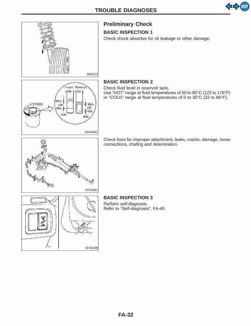
Preliminary CheckBASIC INSPECTION 1Check shock absorber for oil leakage or other damage.
SMA898C
BASIC INSPECTION 2Check fluid level in reservoir tank.Use “HOT” range at fluid temperatures of 50 to 80°C (122 to 176°F)or “COLD” range at fluid temperatures of 0 to 30°C (32 to 86°F).
SST836C
Check lines for improper attachment, leaks, cracks, damage, looseconnections, chafing and deterioration.
SFA929B
BASIC INSPECTION 3Perform self-diagnosis.Refer to “Self-diagnosis”, FA-40.
TROUBLE DIAGNOSES
FA-32
EXITEXIT
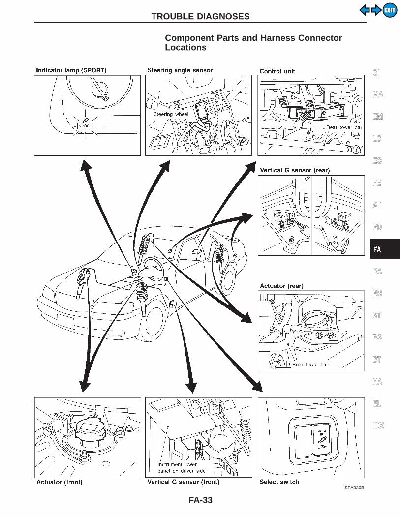
Component Parts and Harness ConnectorLocations
SFA930B
GI
MA
EM
LC
EC
FE
AT
PD
RA
BR
ST
RS
BT
HA
EL
IDX
TROUBLE DIAGNOSES
FA-33
EXITEXIT

Schematic
TFA001M
TROUBLE DIAGNOSES
FA-34
EXITEXIT
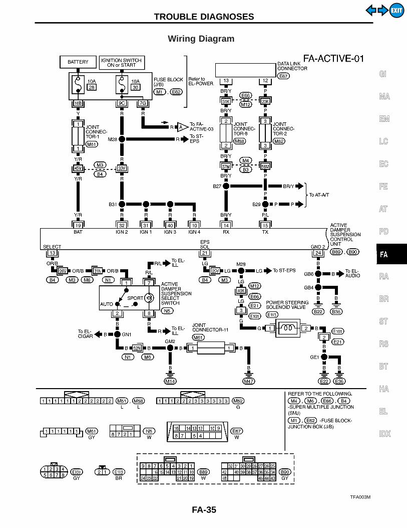
Wiring Diagram
TFA003M
GI
MA
EM
LC
EC
FE
AT
PD
RA
BR
ST
RS
BT
HA
EL
IDX
TROUBLE DIAGNOSES
FA-35
EXITEXIT
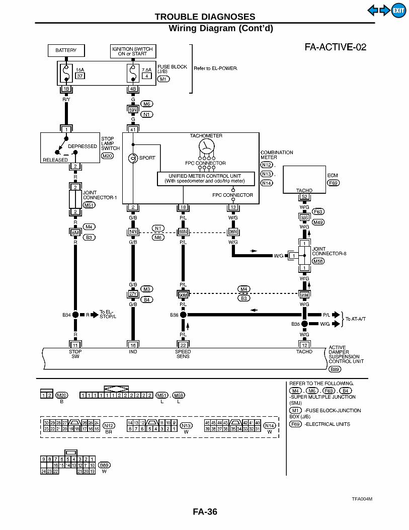
TFA004M
TROUBLE DIAGNOSESWiring Diagram (Cont’d)
FA-36
EXITEXIT

TFA005M
GI
MA
EM
LC
EC
FE
AT
PD
RA
BR
ST
RS
BT
HA
EL
IDX
TROUBLE DIAGNOSESWiring Diagram (Cont’d)
FA-37
EXITEXIT
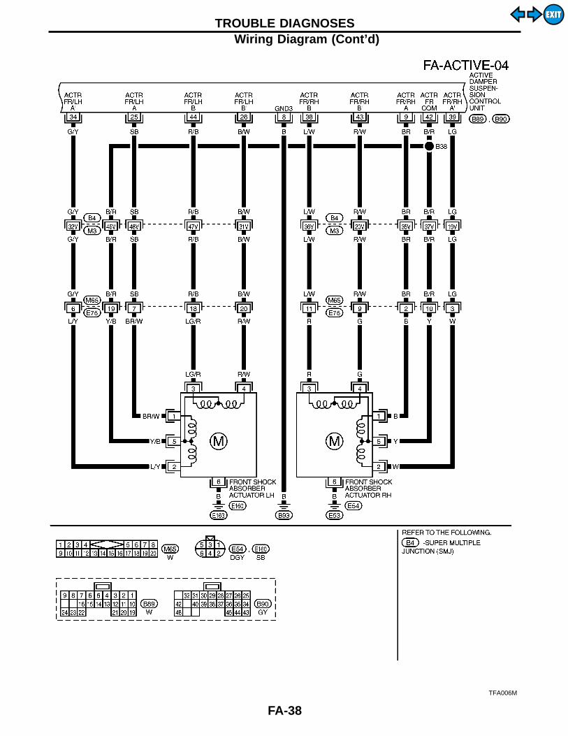
TFA006M
TROUBLE DIAGNOSESWiring Diagram (Cont’d)
FA-38
EXITEXIT
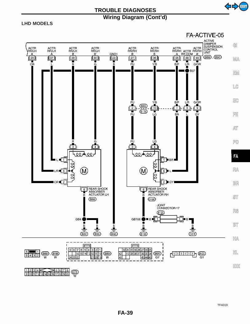
LHD MODELS
TFA019
GI
MA
EM
LC
EC
FE
AT
PD
RA
BR
ST
RS
BT
HA
EL
IDX
TROUBLE DIAGNOSESWiring Diagram (Cont’d)
FA-39
EXITEXIT

Self-diagnosesFUNCTIONThe self-diagnosis system can be used without using CONSULT-II. With this system, both self-diagnostic history and fail-safe historyare indicated by the SPORT indicator lamp.SELF-DIAGNOSTIC PROCEDURE1. Turn ignition switch to “OFF”.2. Start the engine.3. Quickly switch the active damper suspension select switch
from “SPORT” to “AUTO”, and vice versa, at least 5 timeswithin 10 seconds immediately after the engine has started.
2 or 3 seconds following the above switch operation, the indi-cator lamp will come on. This is not the indication of self-di-agnosis.4. Perform the following procedures to enter the corresponding
signals.I Turn steering wheel 180° in either direction from neutral.I Depress brake pedal.I Release brake pedal.I Move the vehicle at least 5 m (16 ft) forward.
SFA931B
HOW TO READ SELF-DIAGNOSTIC RESULTS(Malfunction codes)Following the steps listed under the “Self-diagnostic procedure”above, a faulty area or faulty areas, if any, are indicated by aflashing active damper suspension indicator lamp located in themeter cluster.The indicator lamp flashes to show faulty areas corresponding withNo. 11 through 14, then No. 21, 23 and 24, in that order. 2 secondsafter all items are indicated, the indicator lamp repeats the flashsequence for all items again.I When all items are in good order, the indicator lamp flashes at
a cycle of 1/4 Hz [ON (2 seconds) and OFF (2 seconds)].Display mode:
First digit “ON” (0.6 seconds)Second digit “ON” (0.3 seconds)
I The upper part of the figure at left shows an example of a faultyarea corresponding with No. 23.
I The lower part of the figure at left shows an example of a faultyarea (No. 23) which previously fell under the fail-safe historydata and is still stored in the current fail-safe data history.
After repairing the faulty area(s), erase the self-diagnostic datastored in memory. [Refer to “HOW TO ERASE SELF-DIAGNOS-TIC RESULTS (Malfunction codes)”, FA-41].
TROUBLE DIAGNOSES
FA-40
EXITEXIT
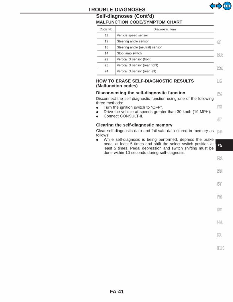
MALFUNCTION CODE/SYMPTOM CHART
Code No. Diagnostic item
11 Vehicle speed sensor
12 Steering angle sensor
13 Steering angle (neutral) sensor
14 Stop lamp switch
22 Vertical G sensor (front)
23 Vertical G sensor (rear right)
24 Vertical G sensor (rear left)
HOW TO ERASE SELF-DIAGNOSTIC RESULTS(Malfunction codes)
Disconnecting the self-diagnostic functionDisconnect the self-diagnostic function using one of the followingthree methods:I Turn the ignition switch to “OFF”.I Drive the vehicle at speeds greater than 30 km/h (19 MPH).I Connect CONSULT-II.
Clearing the self-diagnostic memoryClear self-diagnostic data and fail-safe data stored in memory asfollows:I While self-diagnosis is being performed, depress the brake
pedal at least 5 times and shift the select switch position atleast 5 times. Pedal depression and switch shifting must bedone within 10 seconds during self-diagnosis.
GI
MA
EM
LC
EC
FE
AT
PD
RA
BR
ST
RS
BT
HA
EL
IDX
TROUBLE DIAGNOSESSelf-diagnoses (Cont’d)
FA-41
EXITEXIT

CONSULT-II Inspection ProcedureThe troubleshooting system provides four functional modes — self-diagnosis, data monitor, active test and control unit part numberdisplay modes.
Mode type Description Mode selection Display representation
SELF-DIAG RESULTS Self-diagnosis
The desired functionalmode can easily be
selected by means oftouch keys on CON-
SULT-II.
The desired functionalmode can easily beshown on the CON-
SULT-II display.
DATA MONITOR
I Helps locate main trouble cause according to aself-diagnostic result.
I Provides active damper suspension control unitinput and output monitoring and print-out func-tion (observation and recording).
ACTIVE TEST
I Used to precisely locate the main cause fortrouble according to the self-diagnostic resultobtained in the data monitor mode.
I Provides operational checks of indicator lightand actuator circuits.
ECU PART NUMBERActive damper control unit part numbers areshown on the CONSULT-II display.
ECU (Active damper suspension control unit) partnumber modeIgnore the ECU part number displayed in the ECU PART NUMBERMODE. Refer to parts catalog to order the ECU.
SEF046TA
SELF-DIAGNOSIS PROCEDURE1. Connect CONSULT-II to data link connector and start the
engine.
SFA983B
2. Touch “START”, “ACT D/SUS” and “SELF-DIAG RESULTS”.1) When a faulty item is displayed, record the item.2) Touch “ERASE”.
TROUBLE DIAGNOSES
FA-42
EXITEXIT
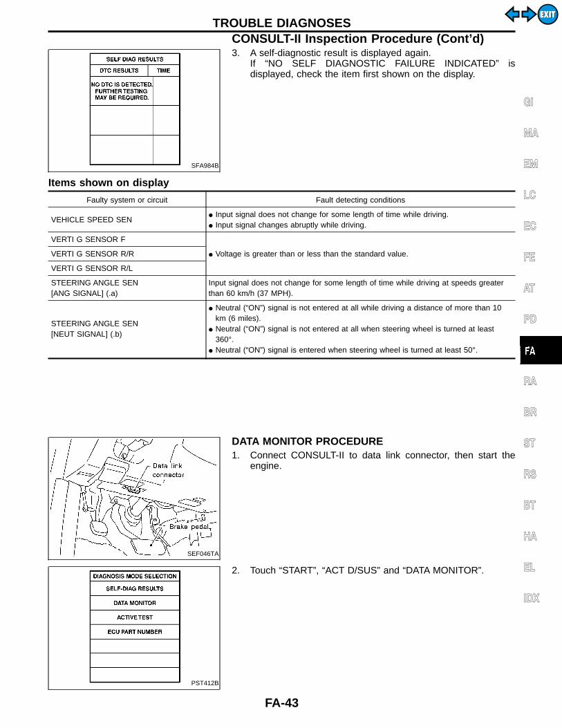
SFA984B
3. A self-diagnostic result is displayed again.If “NO SELF DIAGNOSTIC FAILURE INDICATED” isdisplayed, check the item first shown on the display.
Items shown on display
Faulty system or circuit Fault detecting conditions
VEHICLE SPEED SENI Input signal does not change for some length of time while driving.I Input signal changes abruptly while driving.
VERTI G SENSOR F
I Voltage is greater than or less than the standard value.VERTI G SENSOR R/R
VERTI G SENSOR R/L
STEERING ANGLE SEN[ANG SIGNAL] (.a)
Input signal does not change for some length of time while driving at speeds greaterthan 60 km/h (37 MPH).
STEERING ANGLE SEN[NEUT SIGNAL] (.b)
I Neutral (“ON”) signal is not entered at all while driving a distance of more than 10km (6 miles).
I Neutral (“ON”) signal is not entered at all when steering wheel is turned at least360°.
I Neutral (“ON”) signal is entered when steering wheel is turned at least 50°.
SEF046TA
DATA MONITOR PROCEDURE1. Connect CONSULT-II to data link connector, then start the
engine.
PST412B
2. Touch “START”, “ACT D/SUS” and “DATA MONITOR”.
GI
MA
EM
LC
EC
FE
AT
PD
RA
BR
ST
RS
BT
HA
EL
IDX
TROUBLE DIAGNOSESCONSULT-II Inspection Procedure (Cont’d)
FA-43
EXITEXIT
SFA985B
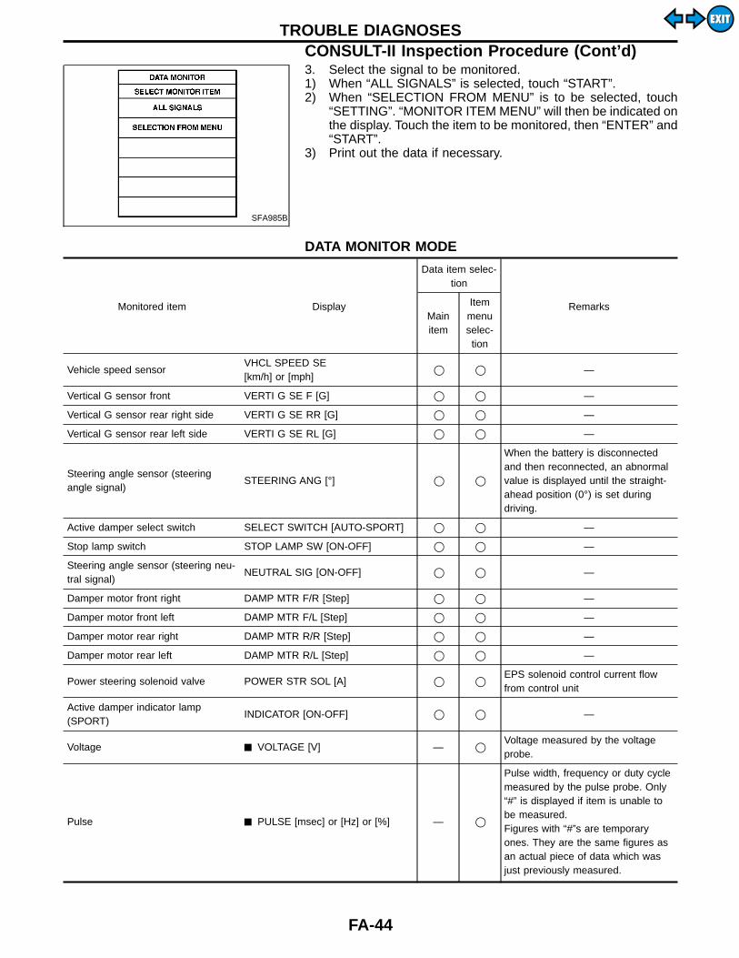
3. Select the signal to be monitored.1) When “ALL SIGNALS” is selected, touch “START”.2) When “SELECTION FROM MENU” is to be selected, touch
“SETTING”. “MONITOR ITEM MENU” will then be indicated onthe display. Touch the item to be monitored, then “ENTER” and“START”.
3) Print out the data if necessary.
DATA MONITOR MODE
Monitored item Display
Data item selec-tion
RemarksMainitem
Itemmenuselec-tion
Vehicle speed sensorVHCL SPEED SE[km/h] or [mph]
q q —
Vertical G sensor front VERTI G SE F [G] q q —
Vertical G sensor rear right side VERTI G SE RR [G] q q —
Vertical G sensor rear left side VERTI G SE RL [G] q q —
Steering angle sensor (steeringangle signal)
STEERING ANG [°] q q
When the battery is disconnectedand then reconnected, an abnormalvalue is displayed until the straight-ahead position (0°) is set duringdriving.
Active damper select switch SELECT SWITCH [AUTO-SPORT] q q —
Stop lamp switch STOP LAMP SW [ON-OFF] q q —
Steering angle sensor (steering neu-tral signal)
NEUTRAL SIG [ON-OFF] q q —
Damper motor front right DAMP MTR F/R [Step] q q —
Damper motor front left DAMP MTR F/L [Step] q q —
Damper motor rear right DAMP MTR R/R [Step] q q —
Damper motor rear left DAMP MTR R/L [Step] q q —
Power steering solenoid valve POWER STR SOL [A] q qEPS solenoid control current flowfrom control unit
Active damper indicator lamp(SPORT)
INDICATOR [ON-OFF] q q —
Voltage ê VOLTAGE [V] — qVoltage measured by the voltageprobe.
Pulse ê PULSE [msec] or [Hz] or [%] — q
Pulse width, frequency or duty cyclemeasured by the pulse probe. Only“#” is displayed if item is unable tobe measured.Figures with “#”s are temporaryones. They are the same figures asan actual piece of data which wasjust previously measured.
TROUBLE DIAGNOSESCONSULT-II Inspection Procedure (Cont’d)
FA-44
EXITEXIT

Specifications for control unit input and output signalsStandard values emitted by CONSULT-IIOutput signals refer to the data which are operated by thecontrol unit. If an output circuit (harness) is broken, normalvalues are displayed.
Items to monitor
Data monitorItems to check
(when abnormal)Reference
pageConditionsReference value(when normal)
VHCL SPEED SE [km/h] or [mph]During driving or drivewheel rotation
Corresponds withspeedometer indication.
Vehicle speed sensorcircuit (Refer to “Diag-nostic Procedure 1”.)
FA-48
VERTI G SE F [G]Vehicle is stopped ona flat road.
Within ±0.15GVertical G sensor cir-cuit (Refer to “Diag-nostic Procedure 4”.)
FA-51VERTI G SE RR [G]
VERTI G SE RL [G]
STEERING ANG [°]Steering wheel isturned in either direc-tion.
Steering wheel angle from neu-tral is displayed.
Steering angle sensorcircuit (Refer to “Diag-nostic Procedure 2”.)
FA-49
SELECT SW [AUTO-SPORT] Select switch positionSet to “AUTO”: AUTOSet to “SPORT”: SPORT
Select switch circuit(Refer to “DiagnosticProcedure 5”.)
FA-52
STOP LAMP SW [ON-OFF] Brake pedal positionBrake pedal is depressed. : ONBrake pedal is released. : OFF
Stop lamp switch cir-cuit (Refer to “Diag-nostic Procedure 3”.)
FA-50
NEUTRAL SIG [ON-OFF]Steering wheel is setat neutral or is turnedin either direction.
Neutral position: ONOther position: OFF
Steering angle sensorcircuit (Refer to “Diag-nostic Procedure 2”.)
FA-49
DAMP MTR F/R [Step]
Actuator position
16 step Shock absorberactuator circuit (Referto “Diagnostic Proce-dure 6”.)
FA-54DAMP MTR F/L [Step]
DAMP MTR R/R [Step]16 step
DAMP MTR R/L [Step]
POWER STR SOL [A]Increase vehiclespeed from 0 to 100km/h (0 to 62 MPH).
0 km/h (0 MPH):Approx. 1.1A100 km/h (62 MPH):Approx. 0.47A
EPS solenoid circuit(Refer to “DiagnosticProcedure 7” and“Diagnostic Procedure8”.)
FA-57FA-58
INDICATOR [ON-OFF]Ignition switch isturned to “ON” orengine is operating.
Indicator lamp is on. : ONIndicator lamp is off. : OFF
Indicator lamp circuit(Refer to “DiagnosticProcedure 5”.)
FA-52
SEF046TA
ACTIVE TEST PROCEDURE1. Connect CONSULT-II to data link connector, then start the
engine.
GI
MA
EM
LC
EC
FE
AT
PD
RA
BR
ST
RS
BT
HA
EL
IDX
TROUBLE DIAGNOSESCONSULT-II Inspection Procedure (Cont’d)
FA-45
EXITEXIT
PST412B
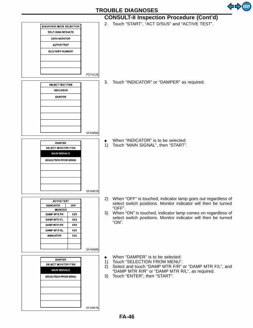
2. Touch “START”, “ACT D/SUS” and “ACTIVE TEST”.
SFA986B
3. Touch “INDICATOR” or “DAMPER” as required.
SFA987B
I When “INDICATOR” is to be selected:1) Touch “MAIN SIGNAL”, then “START”.
SFA988B
2) When “OFF” is touched, indicator lamp goes out regardless ofselect switch positions. Monitor indicator will then be turned“OFF”.
3) When “ON” is touched, indicator lamp comes on regardless ofselect switch positions. Monitor indicator will then be turned“ON”.
SFA987B
I When “DAMPER” is to be selected:1) Touch “SELECTION FROM MENU”.2) Select and touch “DAMP MTR F/R” or “DAMP MTR F/L”, and
“DAMP MTR R/R” or “DAMP MTR R/L”, as required.3) Touch “ENTER”, then “START”.
TROUBLE DIAGNOSESCONSULT-II Inspection Procedure (Cont’d)
FA-46
EXITEXIT

SFA989B
4) “4 step” for front damper motors and “4 step” for rear dampermotor will be then shown on the display.
5) Touch “CONDITION CHANGE”, “FL-N, FR-N, RL-N, RR-N”and “START”.
SFA990B
6) “96 step” for front damper motors and “96 step” for rear dampermotor will then appear on the display.
7) Touch “CONDITION CHANGE”, “FL-HS, FR-HS, RL-HS,RR-HS” and “START”.
SFA991B
8) “0 step” for front damper motors and “0 step” for rear dampermotor will then appear on the display.
9) Touch “CONDITION CHANGE” and “FL-SS, FR-SS, RL-SS,RR-SS” and “START”.
SFA992B
10) “−40 step” for front damper motors and “−40 step” for reardamper motor will then appear on the display.
11) Print out data as required.
GI
MA
EM
LC
EC
FE
AT
PD
RA
BR
ST
RS
BT
HA
EL
IDX
TROUBLE DIAGNOSESCONSULT-II Inspection Procedure (Cont’d)
FA-47
EXITEXIT
SFA936B
SFA937B
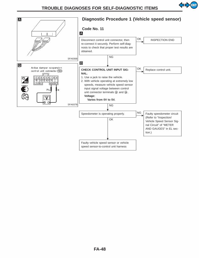
Diagnostic Procedure 1 (Vehicle speed sensor)
Code No. 11
Disconnect control unit connector, thenre-connect it securely. Perform self-diag-nosis to check that proper test results areobtained.
NG
EOK INSPECTION END
CHECK CONTROL UNIT INPUT SIG-NAL.1. Use a jack to raise the vehicle.2. With vehicle operating at extremely low
speeds, measure vehicle speed sensorinput signal voltage between controlunit connector terminals q22 and q24 .Voltage:
Varies from 0V to 5V.
NG
EOK Replace control unit.
Speedometer is operating properly.
OK
ENG Faulty speedometer circuit
(Refer to “Inspection/Vehicle Speed Sensor Sig-nal Circuit” of “METERAND GAUGES” in EL sec-tion.)
Faulty vehicle speed sensor or vehiclespeed sensor-to-control unit harness
TROUBLE DIAGNOSES FOR SELF-DIAGNOSTIC ITEMS
H
H
H
FA-48
EXITEXIT
SFA938B
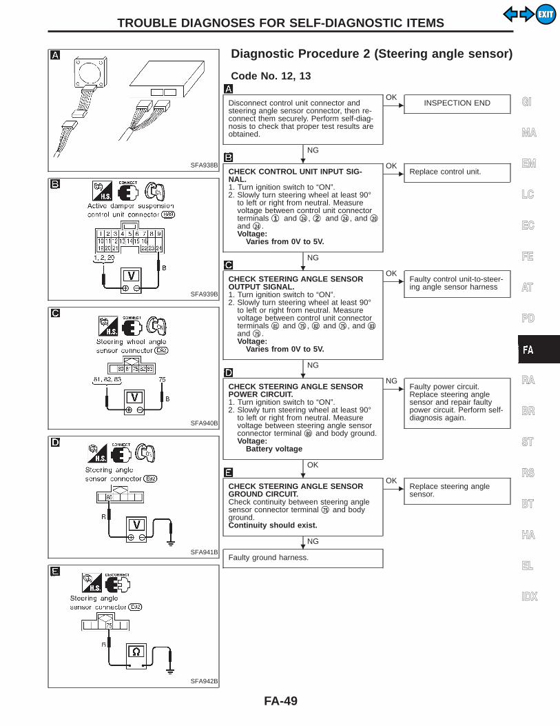
Diagnostic Procedure 2 (Steering angle sensor)
SFA939B
SFA940B
SFA941B
SFA942B
Code No. 12, 13
Disconnect control unit connector andsteering angle sensor connector, then re-connect them securely. Perform self-diag-nosis to check that proper test results areobtained.
NG
EOK
INSPECTION END
CHECK CONTROL UNIT INPUT SIG-NAL.1. Turn ignition switch to “ON”.2. Slowly turn steering wheel at least 90°
to left or right from neutral. Measurevoltage between control unit connectorterminals q1 and q24 , q2 and q24 , and q20and q24 .Voltage:
Varies from 0V to 5V.
NG
EOK
Replace control unit.
CHECK STEERING ANGLE SENSOROUTPUT SIGNAL.1. Turn ignition switch to “ON”.2. Slowly turn steering wheel at least 90°
to left or right from neutral. Measurevoltage between control unit connectorterminals q81 and q75 , q82 and q75 , and q83and q75 .Voltage:
Varies from 0V to 5V.
NG
EOK
Faulty control unit-to-steer-ing angle sensor harness
CHECK STEERING ANGLE SENSORPOWER CIRCUIT.1. Turn ignition switch to “ON”.2. Slowly turn steering wheel at least 90°
to left or right from neutral. Measurevoltage between steering angle sensorconnector terminal q80 and body ground.Voltage:
Battery voltage
OK
ENG
Faulty power circuit.Replace steering anglesensor and repair faultypower circuit. Perform self-diagnosis again.
CHECK STEERING ANGLE SENSORGROUND CIRCUIT.Check continuity between steering anglesensor connector terminal q75 and bodyground.Continuity should exist.
NG
EOK
Replace steering anglesensor.
Faulty ground harness.
GI
MA
EM
LC
EC
FE
AT
PD
RA
BR
ST
RS
BT
HA
EL
IDX
TROUBLE DIAGNOSES FOR SELF-DIAGNOSTIC ITEMS
H
H
H
H
H
FA-49
EXITEXIT
SFA936B
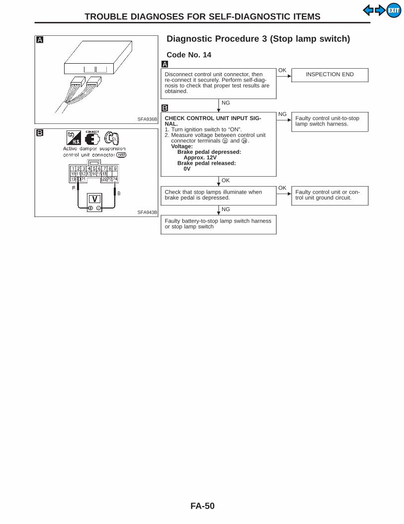
Diagnostic Procedure 3 (Stop lamp switch)
SFA943B
Code No. 14
Disconnect control unit connector, thenre-connect it securely. Perform self-diag-nosis to check that proper test results areobtained.
NG
EOK
INSPECTION END
CHECK CONTROL UNIT INPUT SIG-NAL.1. Turn ignition switch to “ON”.2. Measure voltage between control unit
connector terminals q11 and q24 .Voltage:
Brake pedal depressed:Approx. 12V
Brake pedal released:0V
OK
ENG
Faulty control unit-to-stoplamp switch harness.
Check that stop lamps illuminate whenbrake pedal is depressed.
NG
EOK
Faulty control unit or con-trol unit ground circuit.
Faulty battery-to-stop lamp switch harnessor stop lamp switch
TROUBLE DIAGNOSES FOR SELF-DIAGNOSTIC ITEMS
H
H
H
FA-50
EXITEXIT

SFA944B
Diagnostic Procedure 4 (Vertical G sensor)
SFA945B
SFA946B
SFA968B
SFA947B
Code No. 22, 23, 24
Disconnect control unit connector and ver-tical G sensor connector, then re-connectthem securely. Perform self-diagnosis tocheck that proper test results areobtained.
NG
EOK
INSPECTION END
CHECK CONTROL UNIT VERTICAL GSENSOR POWER CIRCUIT.1. Turn ignition switch to “ON”.2. Measure voltage between control unit
connector terminals q3 and q7 .Voltage:
Approx. 5V
OK
ENG
Faulty control unit or con-trol unit ground circuit.
CHECK CONTROL UNIT VERTICAL GSENSOR INPUT SIGNAL.Measure voltage between control unit con-nector terminals q4 and q24 , q5 and q24 ,and q6 and q24 .Voltage:
Approx. 2.5V
NG
EOK
Replace control unit.
CHECK CONTROL UNIT VERTICAL GSENSOR INPUT SIGNAL CIRCUIT.Check continuity between control unit con-nector terminals q4 , q5 , q6 and q24 .Continuity should not exist.
OK
ENG
Faulty control unit-to-verti-cal G sensor harness.
CHECK VERTICAL G SENSOR OUTPUTSIGNAL.1. Turn ignition switch to “ON”.2. Measure voltage between vertical G
sensor connector terminals q1 and q3and q2 and q3 .Voltage:
q1 — q3Approx. 5V
q2 — q3Approx. 2.5V
OK
ENG
Replace vertical G sensor.
Faulty control unit-to-vertical G sensorharness.
Note: The front vertical G sensor is installed on the rear of the inner pil-lar and the rear vertical G sensor is located on the rear of the outerwheelhouse. To check each vertical G sensor output signal,remove the vertical G sensor, set it vertical, then measure voltagebetween terminals.Be careful not to drop or bump the vertical G sensor as it is easyto break. If dropped or bumped, replace with a new one.
GI
MA
EM
LC
EC
FE
AT
PD
RA
BR
ST
RS
BT
HA
EL
IDX
TROUBLE DIAGNOSES FOR SELF-DIAGNOSTIC ITEMS
H
H
H
H
H
FA-51
EXITEXIT
SFA936B
SFA948B
SFA949B
SFA950B
SFA951B
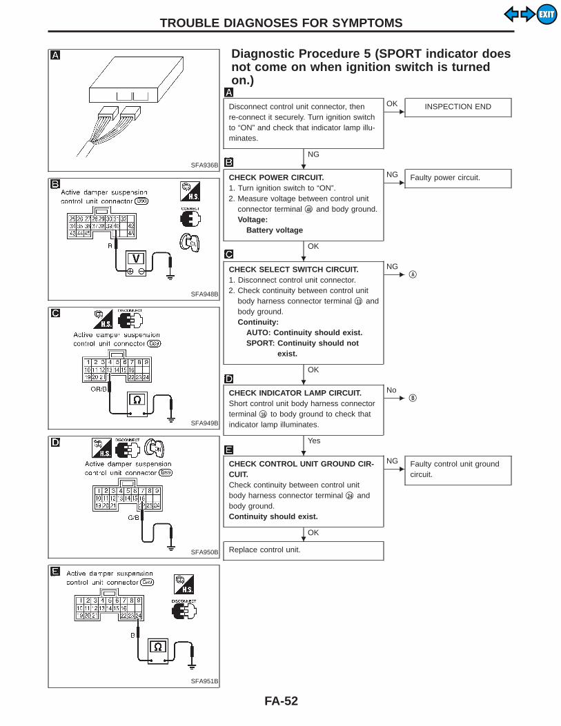
Diagnostic Procedure 5 (SPORT indicator doesnot come on when ignition switch is turnedon.)
Disconnect control unit connector, thenre-connect it securely. Turn ignition switchto “ON” and check that indicator lamp illu-minates.
NG
EOK INSPECTION END
CHECK POWER CIRCUIT.1. Turn ignition switch to “ON”.2. Measure voltage between control unit
connector terminal q40 and body ground.Voltage:
Battery voltage
OK
ENG Faulty power circuit.
CHECK SELECT SWITCH CIRCUIT.1. Disconnect control unit connector.2. Check continuity between control unit
body harness connector terminal q13 andbody ground.Continuity:
AUTO: Continuity should exist.SPORT: Continuity should not
exist.
OK
ENG
qA
CHECK INDICATOR LAMP CIRCUIT.Short control unit body harness connectorterminal q16 to body ground to check thatindicator lamp illuminates.
Yes
ENo
qB
CHECK CONTROL UNIT GROUND CIR-CUIT.Check continuity between control unitbody harness connector terminal q24 andbody ground.Continuity should exist.
OK
ENG Faulty control unit ground
circuit.
Replace control unit.
TROUBLE DIAGNOSES FOR SYMPTOMS
H
H
H
H
H
FA-52
EXITEXIT

SFA952B
SFA953B
qA
CHECK SELECT SWITCH CIRCUIT.Check continuity between control unitbody harness connector terminal q13 andselect switch body harness connector ter-minal q1 .Continuity should exist.
OK
ENG
Faulty control unit-to-selectswitch harness.
CHECK SELECT SWITCH GROUNDCIRCUIT.Check continuity between select switchbody harness connector terminal q2 andbody ground.Continuity should exist.
OK
ENG
Faulty select switch groundcircuit.
Replace select switch.
SFA954B
SFA955B
qB
CHECK INDICATOR LAMP CIRCUIT.Check continuity between control unitbody harness connector terminal q16 andindicator lamp body harness connectorterminal q2 .Continuity should exist.
OK
ENG
Faulty control unit-to-indi-cator lamp harness.
CHECK INDICATOR LAMP.Check continuity between indicator lampmeter connector terminals q41 and q2 .Continuity should exist.
OK
ENG
Replace indicator lamp.
Faulty power circuit.
GI
MA
EM
LC
EC
FE
AT
PD
RA
BR
ST
RS
BT
HA
EL
IDX
TROUBLE DIAGNOSES FOR SYMPTOMSDiagnostic Procedure 5 (SPORT indicator doesnot come on when ignition switch is turnedon.) (Cont’d)
H
H
H
H
H
H
FA-53
EXITEXIT
SFA956B
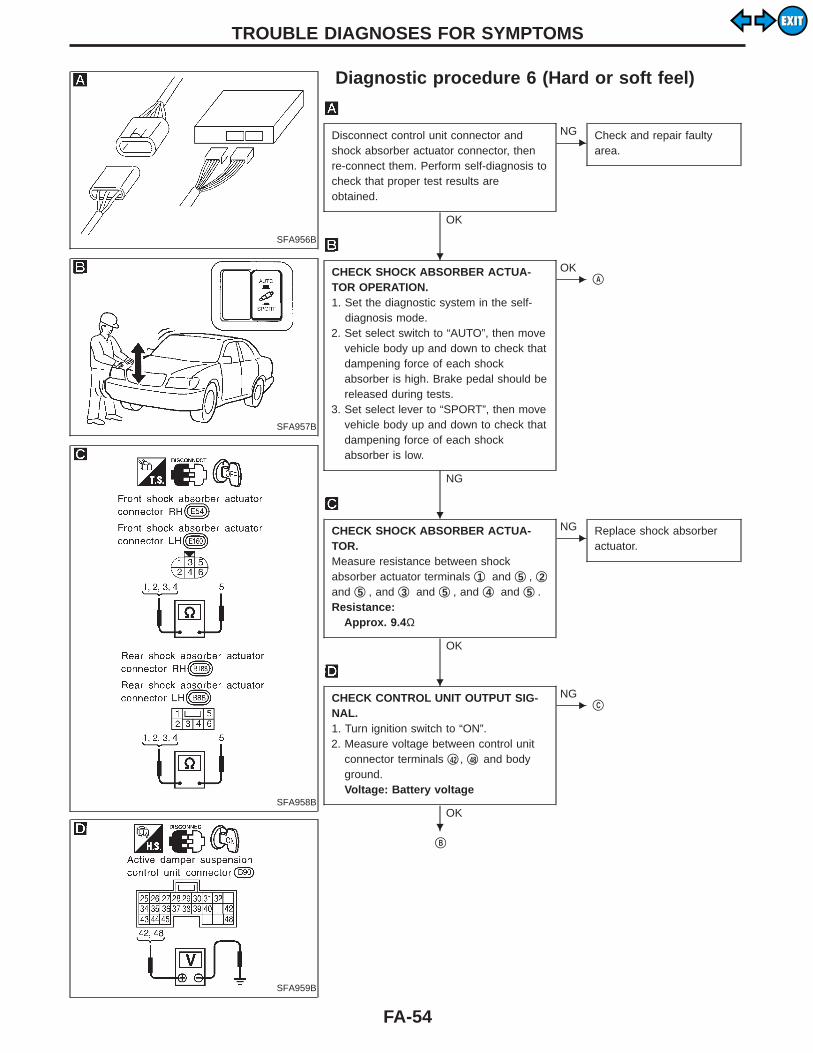
Diagnostic procedure 6 (Hard or soft feel)
SFA957B
SFA958B
SFA959B
Disconnect control unit connector andshock absorber actuator connector, thenre-connect them. Perform self-diagnosis tocheck that proper test results areobtained.
OK
ENG Check and repair faulty
area.
CHECK SHOCK ABSORBER ACTUA-TOR OPERATION.1. Set the diagnostic system in the self-
diagnosis mode.2. Set select switch to “AUTO”, then move
vehicle body up and down to check thatdampening force of each shockabsorber is high. Brake pedal should bereleased during tests.
3. Set select lever to “SPORT”, then movevehicle body up and down to check thatdampening force of each shockabsorber is low.
NG
EOK
qA
CHECK SHOCK ABSORBER ACTUA-TOR.Measure resistance between shockabsorber actuator terminals q1 and q5 , q2and q5 , and q3 and q5 , and q4 and q5 .Resistance:
Approx. 9.4 Ω
OK
ENG Replace shock absorber
actuator.
CHECK CONTROL UNIT OUTPUT SIG-NAL.1. Turn ignition switch to “ON”.2. Measure voltage between control unit
connector terminals q42 , q48 and bodyground.Voltage: Battery voltage
OK
ENG
qC
qB
TROUBLE DIAGNOSES FOR SYMPTOMS
H
H
H
H
FA-54
EXITEXIT
SFA960BA
SFA961B
qB
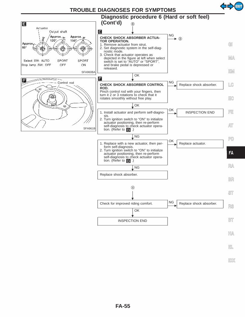
CHECK SHOCK ABSORBER ACTUA-TOR OPERATION.1. Remove actuator from strut.2. Set diagnostic system in the self-diag-
nostic mode.3. Check that actuator operates as
depicted in the figure at left when selectswitch is set to “AUTO” or “SPORT”,and brake pedal is depressed orreleased.
OK
ENG
qD
CHECK SHOCK ABSORBER CONTROLROD.Pinch control rod with your fingers, thenturn it 2 or 3 rotations to check that itrotates smoothly without free play.
OK
ENG
Replace shock absorber.
1. Install actuator and perform self-diagno-sis.
2. Turn ignition switch to “ON” to initializeactuator positioning, then re-performself-diagnosis to check actuator opera-tion. (Refer to .)
NG
EOK
INSPECTION END
1. Replace with a new actuator, then per-form self-diagnosis.
2. Turn ignition switch to “ON” to initializeactuator positioning, then re-performself-diagnosis to check actuator opera-tion. (Refer to .)
NG
EOK
Replace actuator.
Replace shock absorber.
qA
Check for improved riding comfort.
OK
ENG Replace shock absorber.
INSPECTION END
GI
MA
EM
LC
EC
FE
AT
PD
RA
BR
ST
RS
BT
HA
EL
IDX
TROUBLE DIAGNOSES FOR SYMPTOMSDiagnostic procedure 6 (Hard or soft feel)(Cont’d)
H
H
H
H
H
H
H
FA-55
EXITEXIT
SFA962B
qC
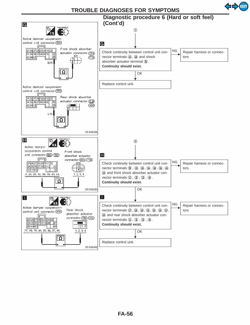
Check continuity between control unit con-nector terminals q42 , q48 and shockabsorber actuator terminal q5 .Continuity should exist.
OK
ENG Repair harness or connec-
tors.
Replace control unit.
SFA963B
SFA964B
qD
Check continuity between control unit con-nector terminals q9 , q25 , q26 , q34 , q38 , q39 , q43 ,q44 and front shock absorber actuator con-nector terminals q1 , q2 , q3 , q4 .Continuity should exist.
OK
ENG Repair harness or connec-
tors.
Check continuity between control unit con-nector terminals q27 , q28 , q29 , q30 , q35 , q36 , q37 ,q45 and rear shock absorber actuator con-nector terminals q1 , q2 , q3 , q4 .Continuity should exist.
OK
ENG Repair harness or connec-
tors.
Replace control unit.
TROUBLE DIAGNOSES FOR SYMPTOMSDiagnostic procedure 6 (Hard or soft feel)(Cont’d)
H
H
H
H
H
FA-56
EXITEXIT
SFA929B
Diagnostic Procedure 7 (Heavy steeringoperation during stationary turns)
SFA965B
SFA966B
SFA697BA
SFA698BA
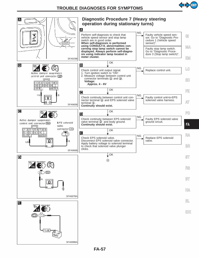
Perform self-diagnosis to check thatvehicle speed sensor and stop lampswitch are in good order.When self-diagnosis is performedusing CONSULT-II, abnormalities con-cerning stop lamp switch cannot bedisplayed. Always perform self-diagno-sis using indicator lamp located inmeter cluster.
OK
ENG
Faulty vehicle speed sen-sor. Go to “Diagnostic Pro-cedure 1 (Vehicle speedsensor)”.
---------------------------------------------------------------------------------------------------------------------------------------------------------------------------------------------------------Faulty stop lamp switch.Go to “Diagnostic Proce-dure 3 (Stop lamp switch)”.
Check control unit output signal.1. Turn ignition switch to “ON”.2. Measure voltage between control unit
connector terminals q21 and q24 .Voltage:
Approx . 4 - 6V
OK
ENG
Replace control unit.
Check continuity between control unit con-nector terminal q21 and EPS solenoid valveterminal q1 .Continuity should exist.
OK
ENG
Faulty control unit-to-EPSsolenoid valve harness.
Check continuity between EPS solenoidvalve terminal q2 and body ground.Continuity should exist.
OK
ENG
Faulty EPS solenoid valveground circuit.
Check EPS solenoid valve.Disconnect EPS solenoid valve connector.Apply battery voltage to solenoid terminalto check that solenoid valve plungerclicks.
OK
ENG
Replace EPS solenoidvalve.
qA
GI
MA
EM
LC
EC
FE
AT
PD
RA
BR
ST
RS
BT
HA
EL
IDX
TROUBLE DIAGNOSES FOR SYMPTOMS
H
H
H
H
H
FA-57
EXITEXIT
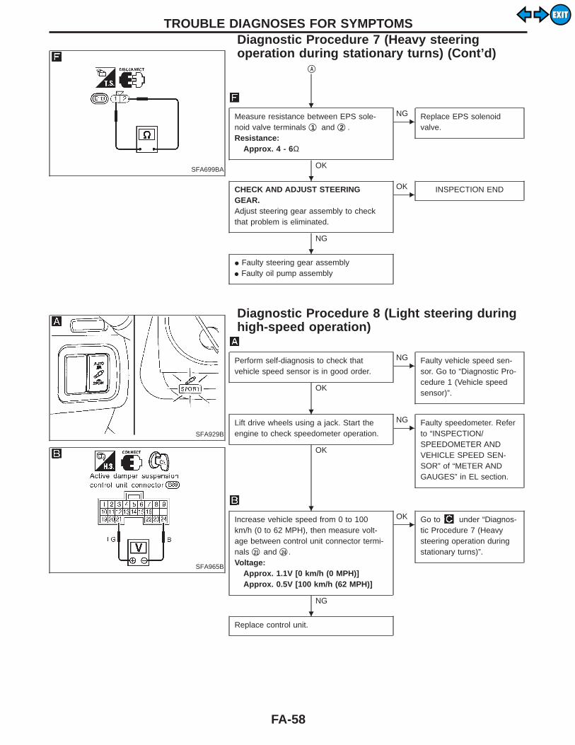
SFA699BA
qA
Measure resistance between EPS sole-noid valve terminals q1 and q2 .Resistance:
Approx . 4 - 6Ω
OK
ENG Replace EPS solenoid
valve.
CHECK AND ADJUST STEERINGGEAR.Adjust steering gear assembly to checkthat problem is eliminated.
NG
EOK INSPECTION END
I Faulty steering gear assemblyI Faulty oil pump assembly
SFA929B
SFA965B
Diagnostic Procedure 8 (Light steering duringhigh-speed operation)
Perform self-diagnosis to check thatvehicle speed sensor is in good order.
OK
ENG Faulty vehicle speed sen-
sor. Go to “Diagnostic Pro-cedure 1 (Vehicle speedsensor)”.
Lift drive wheels using a jack. Start theengine to check speedometer operation.
OK
ENG Faulty speedometer. Refer
to “INSPECTION/SPEEDOMETER ANDVEHICLE SPEED SEN-SOR” of “METER ANDGAUGES” in EL section.
Increase vehicle speed from 0 to 100km/h (0 to 62 MPH), then measure volt-age between control unit connector termi-nals q21 and q24 .Voltage:
Approx. 1.1V [0 km/h (0 MPH)]Approx. 0.5V [100 km/h (62 MPH)]
NG
EOK Go to under “Diagnos-
tic Procedure 7 (Heavysteering operation duringstationary turns)”.
Replace control unit.
TROUBLE DIAGNOSES FOR SYMPTOMSDiagnostic Procedure 7 (Heavy steeringoperation during stationary turns) (Cont’d)
H
H
H
H
H
H
FA-58
EXITEXIT

Electrical Component InspectionINSPECTION OF ACTIVE DAMPER SUSPENSIONCONTROL UNIT
SFA967B
Active damper suspension control unit inspection table
Terminal No.Parts to check Specifications
+ −
10, 19, 3132, 40
Ground
Power supply Turn ignition switch “ON” Battery voltage (Approx. 12V)
8, 23, 24 Ground —
9, 25, 2627, 28, 2930, 34, 3536, 37, 3839, 43, 44
45
Shock absorber actuator—
42, 48 Battery voltage (Approx. 12V)
13 Select switch“SPORT”“AUTO”
0VApprox. 5V
21 EPS solenoidAt 0 km/h (0 MPH)At 100 km/h (62 MPH)
Approx. 1.1AApprox. 0.47A
16 Indicator lamp (SPORT)Select switch set to “SPORT”Select switch set to “AUTO”
0VBattery voltage(Approx. 12V)
1, 2Steering angle sensor
Steering wheel slowly turned toeither side from neutral
0 to 5V (Approx.) are repeated.
20 Steering wheel set to neutral Approx. 5V
11 Stop lamp switchBrake pedal releasedBrake pedal depressed
0VBattery voltage (Approx. 12V)
3 Vertical G sensor power supply — Approx. 5V
4, 5, 6 Vertical G sensor Vehicle standstill Approx. 2.5V
22 Vehicle speed sensor During extremely low speeds 0 to 5V (Approx.) are repeated.
14, 15 — CONSULT-II —
GI
MA
EM
LC
EC
FE
AT
PD
RA
BR
ST
RS
BT
HA
EL
IDX
TROUBLE DIAGNOSES FOR ACTIVE DAMPER SUSPENSION
FA-59
EXITEXIT
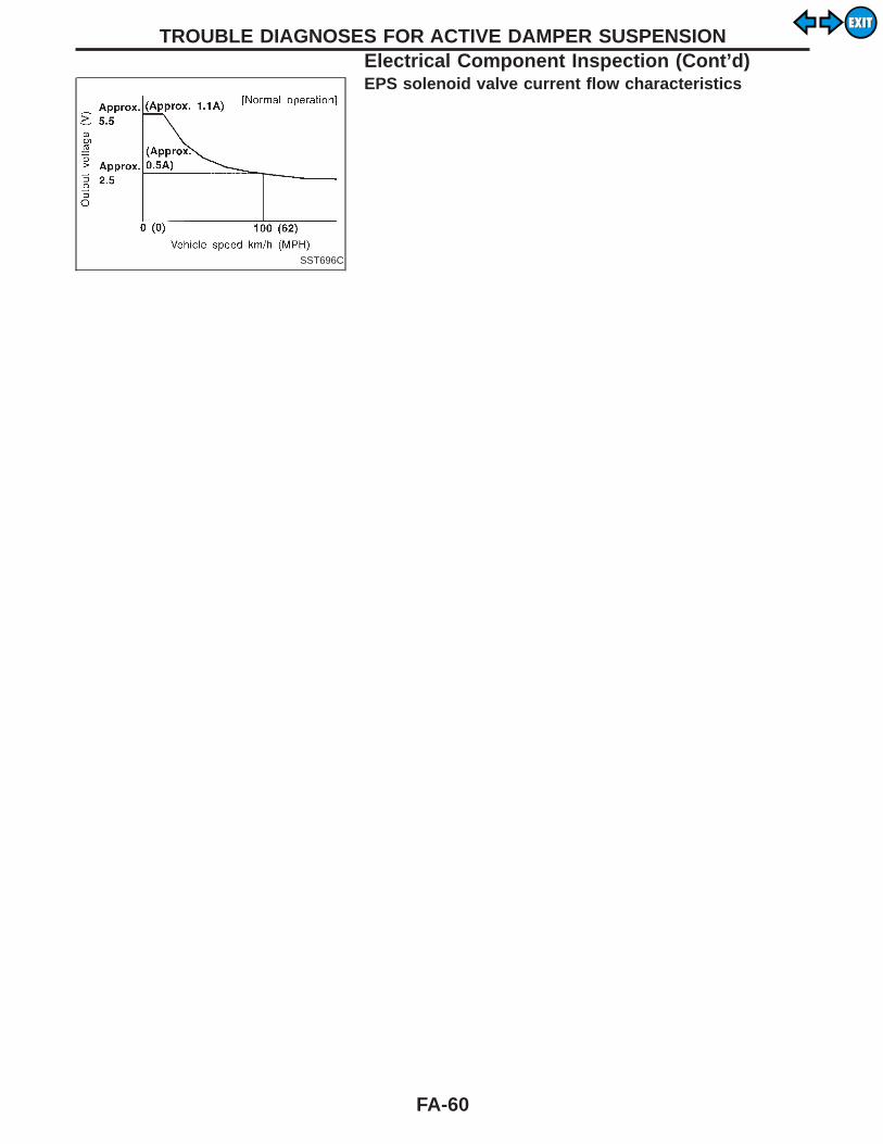
SST696C
EPS solenoid valve current flow characteristics
TROUBLE DIAGNOSES FOR ACTIVE DAMPER SUSPENSIONElectrical Component Inspection (Cont’d)
FA-60
EXITEXIT

General SpecificationsSuspension type Independent macpherson strut with coil spring
Strut typeStandard: Double-acting hydraulic
Optional: Adjusting hydraulic (Active dampersuspension)
Stabilizer bar Standard equipment
Inspection and AdjustmentWHEEL ALIGNMENT (Unladen*1)
Camber Minimum −1°25′ (−1.42°)
Degree minute(Decimal degree)
Nominal −0°40′ (−0.67°)
Maximum 0°05′ (0.08°)
Left and right difference 1° (1.00°) or less
Caster Minimum 5°40′ (5.67°)
Degree minute(Decimal degree)
Nominal 6°25′ (6.42°)
Maximum 7°10′ (7.17°)
Left and right difference 1° (1.00°) or less
Kingpin inclination Minimum 12°25′ (12.42°)
Degree minute(Decimal degree)
Nominal 13°10′ (13.17°)
Maximum 13°55′ (13.92°)
Total toe-in Minimum 1 (0.04)
Distance (A − B)mm (in)
Nominal 2 (0.08)
Maximum 3 (0.12)
Angle (left plus right)Degree minute
(Decimal degree)
Minimum 4′ (0.07°)
Nominal 10′ (0.17°)
Maximum 16′ (0.27°)
Wheel turning angle Minimum 36°50′ (36.83°)
Full turn*2
InsideDegree minute
(Decimal degree)
Nominal 39°50′ (39.83°)
Maximum 40°50′ (40.83°)
OutsideDegree minute
(Decimal degree)Nominal 32°25′ (32.42°)
*1: Fuel, radiator coolant and engine oil full. Spare tire, jack, hand tools and mats in designated positions.*2: On power steering models, wheel turning force (at circumference of steering wheel) of 98 to 147 N (10 to 15 kg, 22 to 33 lb) with engine idle.
GI
MA
EM
LC
EC
FE
AT
PD
RA
BR
ST
RS
BT
HA
EL
IDX
SERVICE DATA AND SPECIFICATIONS (SDS)
FA-61
EXITEXIT

WHEELARCH HEIGHT (Unladen*)
SFA818A
Tire 215/60R16 225/50R17
Front (Hf) mm (in) 731 (28.78) 722 (28.43)
Rear (Hr) mm (in) 734 (28.90) 723 (28.46)
*: Fuel, radiator coolant and engine oil full. Spare tire, jack, hand toolsand mats in designated positions.
WHEEL BEARING
Wheel bearing end play limit mm (in) 0.05 (0.0020) or less
Wheel bearing lock nut
Tightening torque N⋅m (kg-m, ft-lb)206 - 284
(21 - 29, 152 - 210)
Maximum wheel bearing preload measured atwheel hub bolt N (kg, lb)
37.2 (3.8, 8.4)
LOWER BALL JOINT
Swinging force at cotter pin holeN (kg, lb)
8.8 - 85.3(0.9 - 8.7, 2.0 - 19.2)
Turning torque N⋅m (kg-cm, in-lb)0.5 - 4.9
(5 - 50, 4.3 - 43)
Vertical end play mm (in) 0 (0)
WHEEL RUNOUT (Radial and lateral)
Wheel type Aluminum wheel
Radial runout limit mm (in)0.3 (0.012) or less
Lateral runout limit mm (in)
SERVICE DATA AND SPECIFICATIONS (SDS)Inspection and Adjustment (Cont’d)
FA-62
EXITEXIT