Embed Size (px)
DESCRIPTION
2005-2008 Acura RL
Citation preview
2005-08 SUSPENSION
Front Suspension - RL
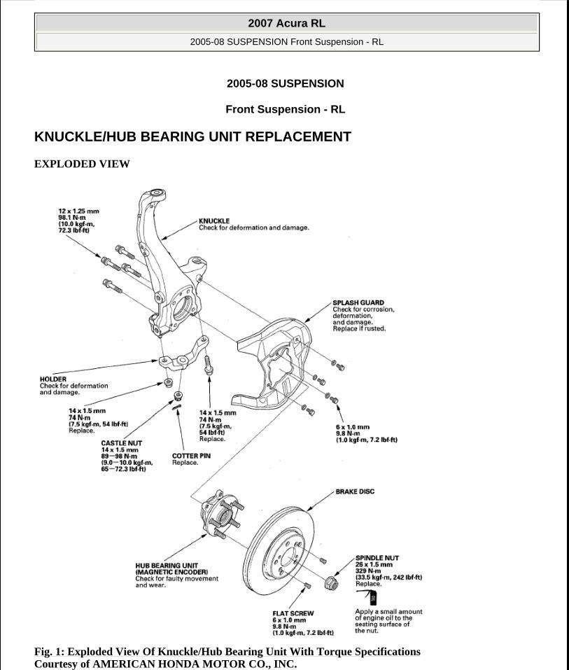
KNUCKLE/HUB BEARING UNIT REPLACEMENT
EXPLODED VIEW
Fig. 1: Exploded View Of Knuckle/Hub Bearing Unit With Torque Specifications Courtesy of AMERICAN HONDA MOTOR CO., INC.
2007 Acura RL
2005-08 SUSPENSION Front Suspension - RL
2007 Acura RL
2005-08 SUSPENSION Front Suspension - RL
me
Friday, June 05, 2009 1:20:39 PM Page 1 © 2005 Mitchell Repair Information Company, LLC.
me
Friday, June 05, 2009 1:20:43 PM Page 1 © 2005 Mitchell Repair Information Company, LLC.
Special Tools Required
Ball joint remover, 32 mm 07MAC-SL0A1O2
HUB BEARING UNIT REPLACEMENT
1. Raise the front of the vehicle, and support it with safety stands in the proper locations (see LIFT AND SUPPORT POINTS ).
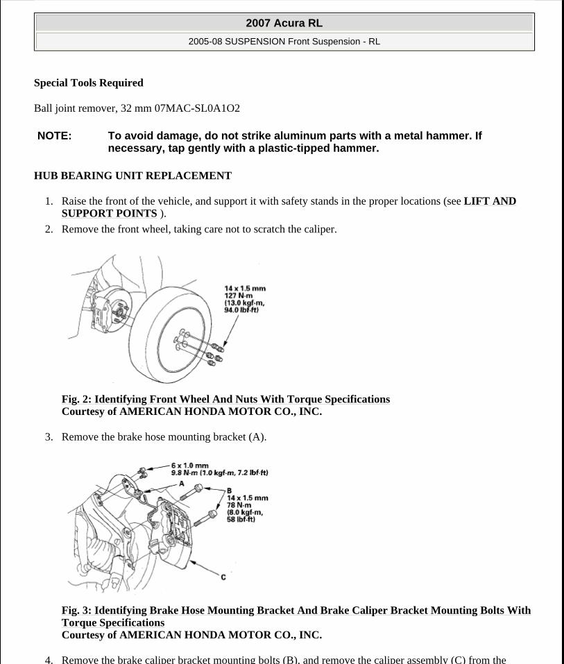
2. Remove the front wheel, taking care not to scratch the caliper.
Fig. 2: Identifying Front Wheel And Nuts With Torque Specifications Courtesy of AMERICAN HONDA MOTOR CO., INC.
3. Remove the brake hose mounting bracket (A).
Fig. 3: Identifying Brake Hose Mounting Bracket And Brake Caliper Bracket Mounting Bolts With Torque Specifications Courtesy of AMERICAN HONDA MOTOR CO., INC.
4. Remove the brake caliper bracket mounting bolts (B), and remove the caliper assembly (C) from the
NOTE: To avoid damage, do not strike aluminum parts with a metal hammer. If necessary, tap gently with a plastic-tipped hammer.
2007 Acura RL
2005-08 SUSPENSION Front Suspension - RL
me
Friday, June 05, 2009 1:20:39 PM Page 2 © 2005 Mitchell Repair Information Company, LLC.
knuckle. To prevent damage to the caliper assembly or brake hose, use a short piece of wire to hang the caliper assembly from the undercarriage. Do not twist the brake hose with force.
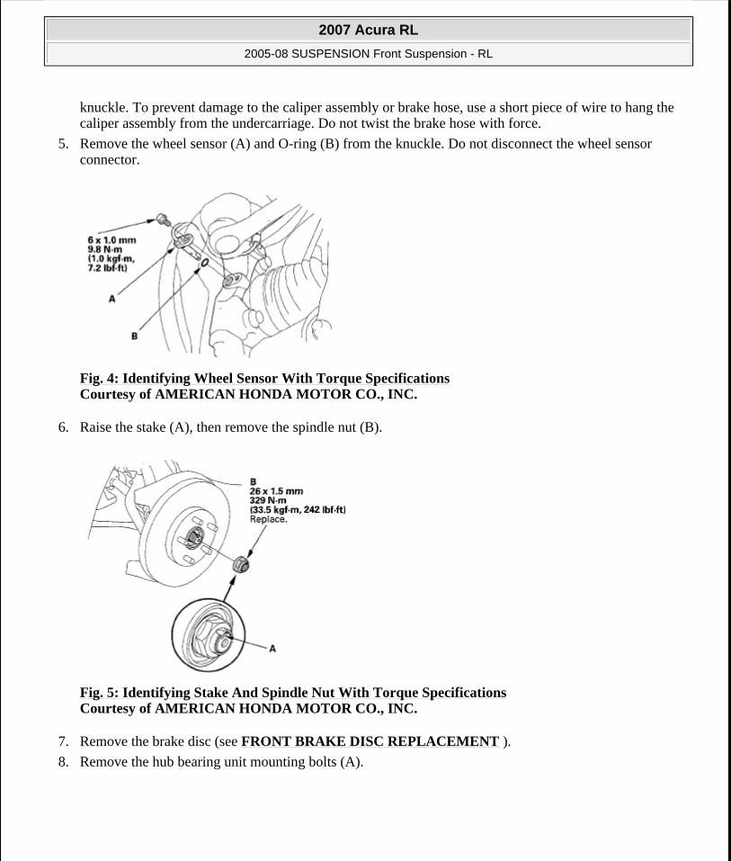
5. Remove the wheel sensor (A) and O-ring (B) from the knuckle. Do not disconnect the wheel sensor connector.
Fig. 4: Identifying Wheel Sensor With Torque Specifications Courtesy of AMERICAN HONDA MOTOR CO., INC.
6. Raise the stake (A), then remove the spindle nut (B).
Fig. 5: Identifying Stake And Spindle Nut With Torque Specifications Courtesy of AMERICAN HONDA MOTOR CO., INC.
7. Remove the brake disc (see FRONT BRAKE DISC REPLACEMENT ).
8. Remove the hub bearing unit mounting bolts (A).
2007 Acura RL
2005-08 SUSPENSION Front Suspension - RL
me
Friday, June 05, 2009 1:20:39 PM Page 3 © 2005 Mitchell Repair Information Company, LLC.
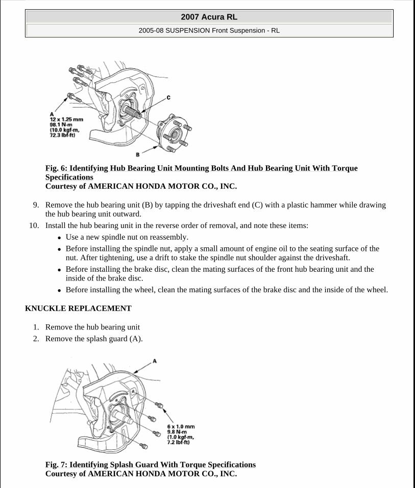
Fig. 6: Identifying Hub Bearing Unit Mounting Bolts And Hub Bearing Unit With Torque Specifications Courtesy of AMERICAN HONDA MOTOR CO., INC.
9. Remove the hub bearing unit (B) by tapping the driveshaft end (C) with a plastic hammer while drawing the hub bearing unit outward.
10. Install the hub bearing unit in the reverse order of removal, and note these items:
Use a new spindle nut on reassembly.
Before installing the spindle nut, apply a small amount of engine oil to the seating surface of the nut. After tightening, use a drift to stake the spindle nut shoulder against the driveshaft.
Before installing the brake disc, clean the mating surfaces of the front hub bearing unit and the inside of the brake disc.
Before installing the wheel, clean the mating surfaces of the brake disc and the inside of the wheel.
KNUCKLE REPLACEMENT
1. Remove the hub bearing unit
2. Remove the splash guard (A).
Fig. 7: Identifying Splash Guard With Torque Specifications Courtesy of AMERICAN HONDA MOTOR CO., INC.
2007 Acura RL
2005-08 SUSPENSION Front Suspension - RL
me
Friday, June 05, 2009 1:20:39 PM Page 4 © 2005 Mitchell Repair Information Company, LLC.

3. Remove the wheel sensor (A) from the knuckle. Do not disconnect the wheel sensor connector.
Fig. 8: Identifying Wheel Sensor, Wheel Sensor Bracket And Clips Courtesy of AMERICAN HONDA MOTOR CO., INC.
4. Remove the cotter pin (A) from the tie-rod end ball joint, then loosen the nut (B).
Fig. 9: Identifying Cotter Pin And Nut With Torque Specifications Courtesy of AMERICAN HONDA MOTOR CO., INC.
5. Disconnect the tie-rod end ball joint from the knuckle using the ball joint remover (see BALL JOINT REMOVAL ).
NOTE: Use a new wheel sensor bracket (B) and new clips (C) on reassembly.
NOTE: During installation, install the new cotter pin after tightening the nut, and bend its end as shown.
2007 Acura RL
2005-08 SUSPENSION Front Suspension - RL
me
Friday, June 05, 2009 1:20:39 PM Page 5 © 2005 Mitchell Repair Information Company, LLC.
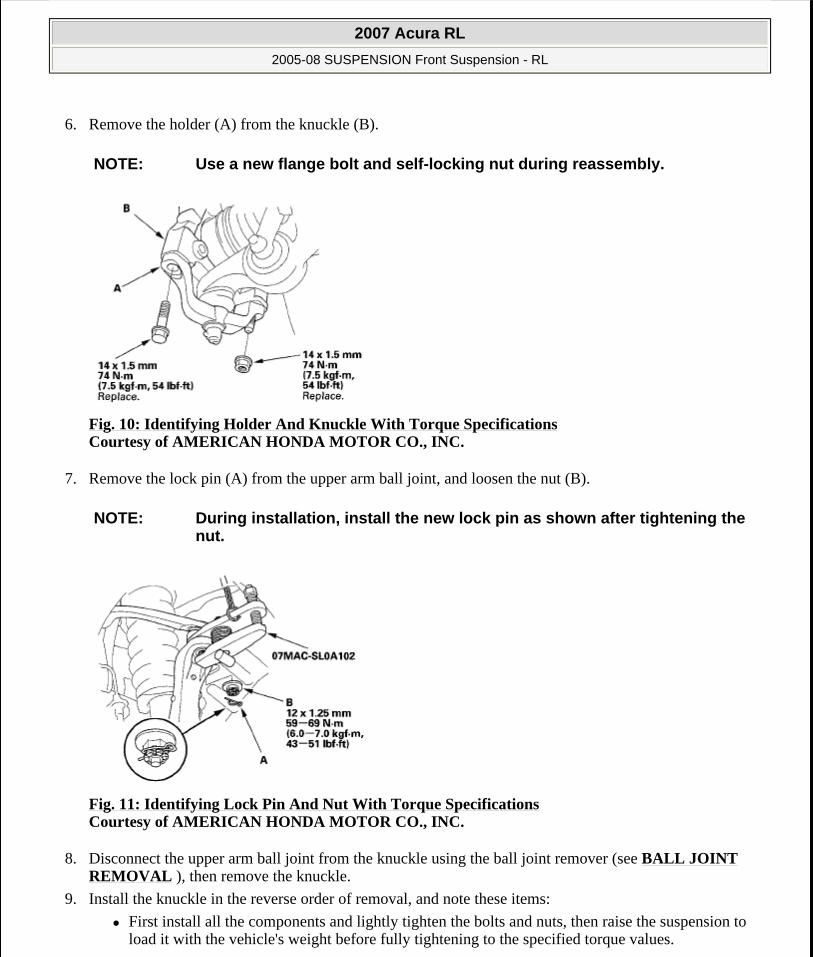
6. Remove the holder (A) from the knuckle (B).
Fig. 10: Identifying Holder And Knuckle With Torque Specifications Courtesy of AMERICAN HONDA MOTOR CO., INC.
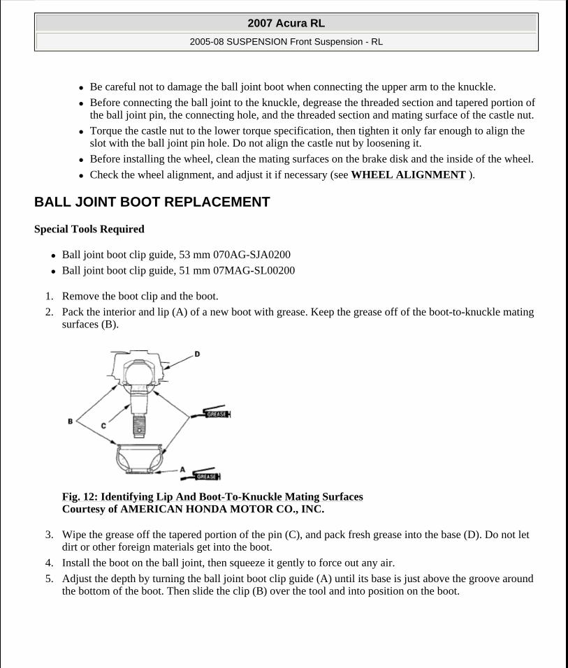
7. Remove the lock pin (A) from the upper arm ball joint, and loosen the nut (B).
Fig. 11: Identifying Lock Pin And Nut With Torque Specifications Courtesy of AMERICAN HONDA MOTOR CO., INC.
8. Disconnect the upper arm ball joint from the knuckle using the ball joint remover (see BALL JOINT REMOVAL ), then remove the knuckle.
9. Install the knuckle in the reverse order of removal, and note these items:
First install all the components and lightly tighten the bolts and nuts, then raise the suspension to load it with the vehicle's weight before fully tightening to the specified torque values.
NOTE: Use a new flange bolt and self-locking nut during reassembly.
NOTE: During installation, install the new lock pin as shown after tightening the nut.
2007 Acura RL
2005-08 SUSPENSION Front Suspension - RL
me
Friday, June 05, 2009 1:20:39 PM Page 6 © 2005 Mitchell Repair Information Company, LLC.
Be careful not to damage the ball joint boot when connecting the upper arm to the knuckle.
Before connecting the ball joint to the knuckle, degrease the threaded section and tapered portion of the ball joint pin, the connecting hole, and the threaded section and mating surface of the castle nut.
Torque the castle nut to the lower torque specification, then tighten it only far enough to align the slot with the ball joint pin hole. Do not align the castle nut by loosening it.
Before installing the wheel, clean the mating surfaces on the brake disk and the inside of the wheel.
Check the wheel alignment, and adjust it if necessary (see WHEEL ALIGNMENT ).
BALL JOINT BOOT REPLACEMENT
Special Tools Required
Ball joint boot clip guide, 53 mm 070AG-SJA0200
Ball joint boot clip guide, 51 mm 07MAG-SL00200
1. Remove the boot clip and the boot.
2. Pack the interior and lip (A) of a new boot with grease. Keep the grease off of the boot-to-knuckle mating surfaces (B).
Fig. 12: Identifying Lip And Boot-To-Knuckle Mating Surfaces Courtesy of AMERICAN HONDA MOTOR CO., INC.
3. Wipe the grease off the tapered portion of the pin (C), and pack fresh grease into the base (D). Do not let dirt or other foreign materials get into the boot.
4. Install the boot on the ball joint, then squeeze it gently to force out any air.
5. Adjust the depth by turning the ball joint boot clip guide (A) until its base is just above the groove around the bottom of the boot. Then slide the clip (B) over the tool and into position on the boot.
2007 Acura RL
2005-08 SUSPENSION Front Suspension - RL
me
Friday, June 05, 2009 1:20:39 PM Page 7 © 2005 Mitchell Repair Information Company, LLC.
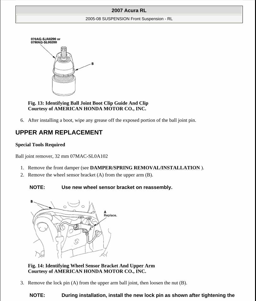
Fig. 13: Identifying Ball Joint Boot Clip Guide And Clip Courtesy of AMERICAN HONDA MOTOR CO., INC.
6. After installing a boot, wipe any grease off the exposed portion of the ball joint pin.
UPPER ARM REPLACEMENT
Special Tools Required
Ball joint remover, 32 mm 07MAC-SL0A102
1. Remove the front damper (see DAMPER/SPRING REMOVAL/INSTALLATION ).
2. Remove the wheel sensor bracket (A) from the upper arm (B).
Fig. 14: Identifying Wheel Sensor Bracket And Upper Arm Courtesy of AMERICAN HONDA MOTOR CO., INC.
3. Remove the lock pin (A) from the upper arm ball joint, then loosen the nut (B).
NOTE: Use new wheel sensor bracket on reassembly.
NOTE: During installation, install the new lock pin as shown after tightening the
2007 Acura RL
2005-08 SUSPENSION Front Suspension - RL
me
Friday, June 05, 2009 1:20:39 PM Page 8 © 2005 Mitchell Repair Information Company, LLC.

Fig. 15: Identifying Lock Pin And Nut With Torque Specifications Courtesy of AMERICAN HONDA MOTOR CO., INC.
4. Disconnect the upper arm ball joint from the knuckle using the ball joint remover (see BALL JOINT REMOVAL ).
5. Remove the upper arm mounting bolts (A), then remove the upper arm (B).
Fig. 16: Identifying Upper Arm Mounting Bolts And Upper Arm Courtesy of AMERICAN HONDA MOTOR CO., INC.
6. Install the upper arm by inserting a rod (A) of appropriate size (O.D. 6 mm/L: 300 mm) into the positioning holes (B), and place the upper arm (C) on the rod to position it before tightening the upper arm mounting bolts.
castle nut.
NOTE: Use the new upper arm mounting bolts during reassembly.
2007 Acura RL
2005-08 SUSPENSION Front Suspension - RL
me
Friday, June 05, 2009 1:20:39 PM Page 9 © 2005 Mitchell Repair Information Company, LLC.

Fig. 17: Identifying Rod, Holes And Upper Arm With Torque Specifications Courtesy of AMERICAN HONDA MOTOR CO., INC.
7. Install the remaining parts in the reverse order of removal, and note these items:
First install all the components and lightly tighten the bolts and nuts, then raise the suspension to load it with the vehicle's weight before fully tightening to the specified torque values. Do not place the jack against the ball joint pin of the knuckle.
Be careful not to damage the ball joint boot when installing the knuckle.
Before connecting the ball joint to the knuckle, degrease the threaded section and tapered portion of the ball joint pin, the knuckle connecting hole, and the threaded section and mating surface of the castle nut.
Torque the castle nut to the lower torque specification, then tighten it only far enough to align the slot with the ball joint pin hole. Do not align the castle nut by loosening it.
Before installing the wheel, clean the mating surfaces on the brake disc and the inside of the wheel.
Check the front wheel alignment, and adjust it if necessary (see WHEEL ALIGNMENT ).
LOWER ARM REMOVAL/INSTALLATION
Special Tools Required
Ball joint remover, 32 mm 07MAC-SLOA102
1. Raise the front of the vehicle, and support it with safety stands in the proper locations (see LIFT AND SUPPORT POINTS ).
2. Remove the front wheels taking care not to scratch the caliper.
3. Remove the holder (A) from the knuckle (B).
NOTE: Use a new flange bolt and a new self-locking nut during reassembly.
2007 Acura RL
2005-08 SUSPENSION Front Suspension - RL
me
Friday, June 05, 2009 1:20:39 PM Page 10 © 2005 Mitchell Repair Information Company, LLC.
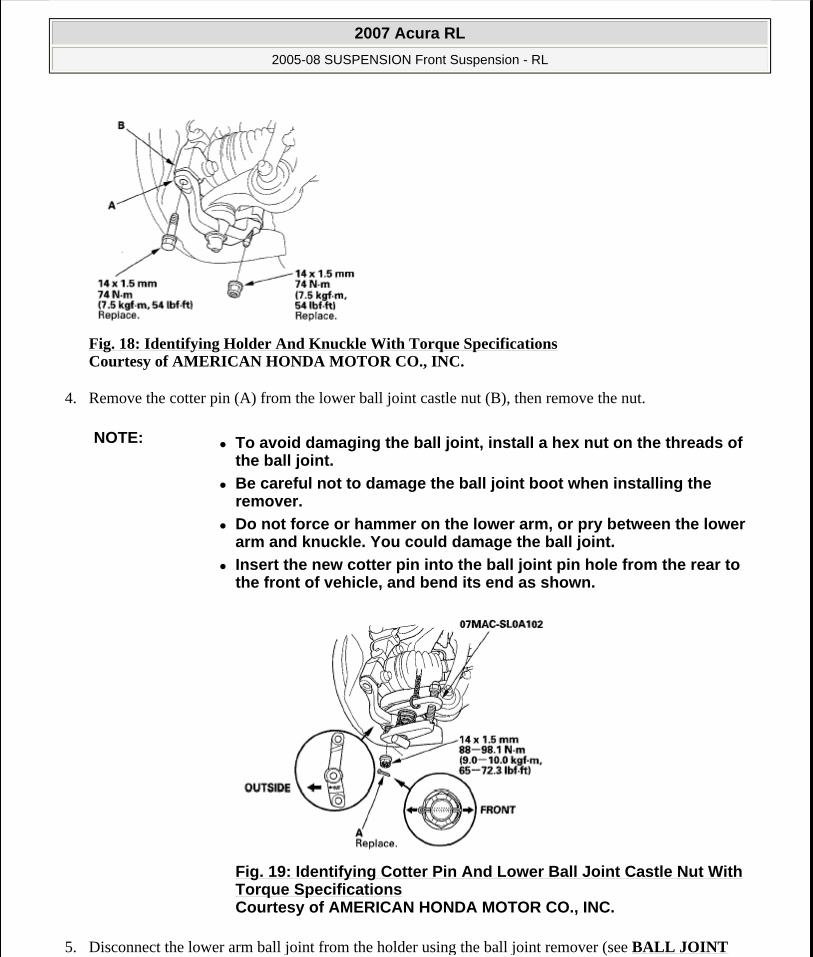
Fig. 18: Identifying Holder And Knuckle With Torque Specifications Courtesy of AMERICAN HONDA MOTOR CO., INC.
4. Remove the cotter pin (A) from the lower ball joint castle nut (B), then remove the nut.
5. Disconnect the lower arm ball joint from the holder using the ball joint remover (see BALL JOINT
NOTE: To avoid damaging the ball joint, install a hex nut on the threads of the ball joint.
Be careful not to damage the ball joint boot when installing the remover.
Do not force or hammer on the lower arm, or pry between the lower arm and knuckle. You could damage the ball joint.
Insert the new cotter pin into the ball joint pin hole from the rear to the front of vehicle, and bend its end as shown.
Fig. 19: Identifying Cotter Pin And Lower Ball Joint Castle Nut With Torque Specifications Courtesy of AMERICAN HONDA MOTOR CO., INC.
2007 Acura RL
2005-08 SUSPENSION Front Suspension - RL
me
Friday, June 05, 2009 1:20:39 PM Page 11 © 2005 Mitchell Repair Information Company, LLC.
REMOVAL ).
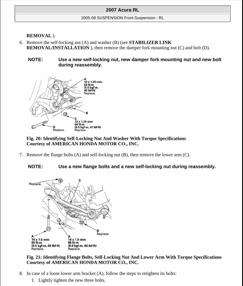
6. Remove the self-locking nut (A) and washer (B) (see STABILIZER LINK REMOVAL/INSTALLATION ), then remove the damper fork mounting nut (C) and bolt (D).
Fig. 20: Identifying Self-Locking Nut And Washer With Torque Specifications Courtesy of AMERICAN HONDA MOTOR CO., INC.
7. Remove the flange bolts (A) and self-locking nut (B), then remove the lower arm (C).
Fig. 21: Identifying Flange Bolts, Self-Locking Nut And Lower Arm With Torque Specifications Courtesy of AMERICAN HONDA MOTOR CO., INC.
8. In case of a loose lower arm bracket (A), follow the steps to retighten its bolts:
1. Lightly tighten the new three bolts.
NOTE: Use a new self-locking nut, new damper fork mounting nut and new bolt during reassembly.
NOTE: Use a new flange bolts and a new self-locking nut during reassembly.
2007 Acura RL
2005-08 SUSPENSION Front Suspension - RL
me
Friday, June 05, 2009 1:20:39 PM Page 12 © 2005 Mitchell Repair Information Company, LLC.
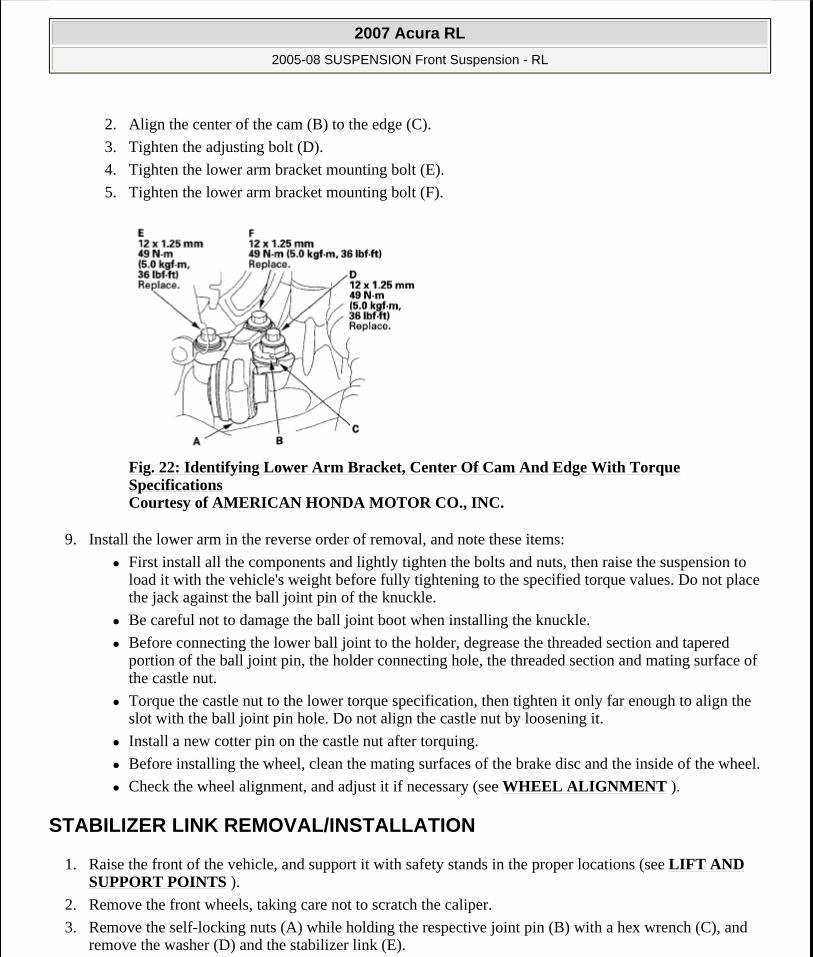
2. Align the center of the cam (B) to the edge (C).
3. Tighten the adjusting bolt (D).
4. Tighten the lower arm bracket mounting bolt (E).
5. Tighten the lower arm bracket mounting bolt (F).
Fig. 22: Identifying Lower Arm Bracket, Center Of Cam And Edge With Torque Specifications Courtesy of AMERICAN HONDA MOTOR CO., INC.
9. Install the lower arm in the reverse order of removal, and note these items:
First install all the components and lightly tighten the bolts and nuts, then raise the suspension to load it with the vehicle's weight before fully tightening to the specified torque values. Do not place the jack against the ball joint pin of the knuckle.
Be careful not to damage the ball joint boot when installing the knuckle.
Before connecting the lower ball joint to the holder, degrease the threaded section and tapered portion of the ball joint pin, the holder connecting hole, the threaded section and mating surface of the castle nut.
Torque the castle nut to the lower torque specification, then tighten it only far enough to align the slot with the ball joint pin hole. Do not align the castle nut by loosening it.
Install a new cotter pin on the castle nut after torquing.
Before installing the wheel, clean the mating surfaces of the brake disc and the inside of the wheel.
Check the wheel alignment, and adjust it if necessary (see WHEEL ALIGNMENT ).
STABILIZER LINK REMOVAL/INSTALLATION
1. Raise the front of the vehicle, and support it with safety stands in the proper locations (see LIFT AND SUPPORT POINTS ).
2. Remove the front wheels, taking care not to scratch the caliper.
3. Remove the self-locking nuts (A) while holding the respective joint pin (B) with a hex wrench (C), and remove the washer (D) and the stabilizer link (E).
2007 Acura RL
2005-08 SUSPENSION Front Suspension - RL
me
Friday, June 05, 2009 1:20:39 PM Page 13 © 2005 Mitchell Repair Information Company, LLC.
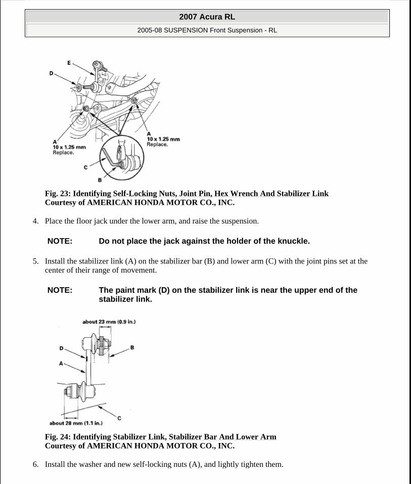
Fig. 23: Identifying Self-Locking Nuts, Joint Pin, Hex Wrench And Stabilizer Link Courtesy of AMERICAN HONDA MOTOR CO., INC.
4. Place the floor jack under the lower arm, and raise the suspension.
5. Install the stabilizer link (A) on the stabilizer bar (B) and lower arm (C) with the joint pins set at the center of their range of movement.
Fig. 24: Identifying Stabilizer Link, Stabilizer Bar And Lower Arm Courtesy of AMERICAN HONDA MOTOR CO., INC.
6. Install the washer and new self-locking nuts (A), and lightly tighten them.
NOTE: Do not place the jack against the holder of the knuckle.
NOTE: The paint mark (D) on the stabilizer link is near the upper end of the stabilizer link.
2007 Acura RL
2005-08 SUSPENSION Front Suspension - RL
me
Friday, June 05, 2009 1:20:39 PM Page 14 © 2005 Mitchell Repair Information Company, LLC.
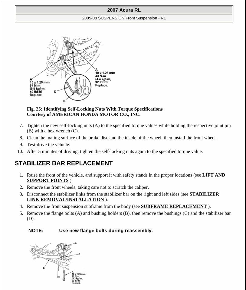
Fig. 25: Identifying Self-Locking Nuts With Torque Specifications Courtesy of AMERICAN HONDA MOTOR CO., INC.
7. Tighten the new self-locking nuts (A) to the specified torque values while holding the respective joint pin (B) with a hex wrench (C).
8. Clean the mating surface of the brake disc and the inside of the wheel, then install the front wheel.
9. Test-drive the vehicle.
10. After 5 minutes of driving, tighten the self-locking nuts again to the specified torque value.
STABILIZER BAR REPLACEMENT
1. Raise the front of the vehicle, and support it with safety stands in the proper locations (see LIFT AND SUPPORT POINTS ).
2. Remove the front wheels, taking care not to scratch the caliper.
3. Disconnect the stabilizer links from the stabilizer bar on the right and left sides (see STABILIZER LINK REMOVAL/INSTALLATION ).
4. Remove the front suspension subframe from the body (see SUBFRAME REPLACEMENT ).
5. Remove the flange bolts (A) and bushing holders (B), then remove the bushings (C) and the stabilizer bar (D).
NOTE: Use new flange bolts during reassembly.
2007 Acura RL
2005-08 SUSPENSION Front Suspension - RL
me
Friday, June 05, 2009 1:20:39 PM Page 15 © 2005 Mitchell Repair Information Company, LLC.
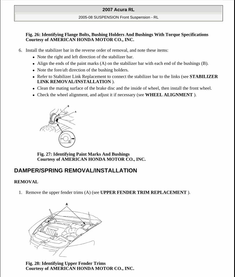
Fig. 26: Identifying Flange Bolts, Bushing Holders And Bushings With Torque SpecificationsCourtesy of AMERICAN HONDA MOTOR CO., INC.
6. Install the stabilizer bar in the reverse order of removal, and note these items:
Note the right and left direction of the stabilizer bar.
Align the ends of the paint marks (A) on the stabilizer bar with each end of the bushings (B).
Note the fore/aft direction of the bushing holders.
Refer to Stabilizer Link Replacement to connect the stabilizer bar to the links (see STABILIZER LINK REMOVAL/INSTALLATION ).
Clean the mating surface of the brake disc and the inside of wheel, then install the front wheel.
Check the wheel alignment, and adjust it if necessary (see WHEEL ALIGNMENT ).
Fig. 27: Identifying Paint Marks And Bushings Courtesy of AMERICAN HONDA MOTOR CO., INC.
DAMPER/SPRING REMOVAL/INSTALLATION
REMOVAL
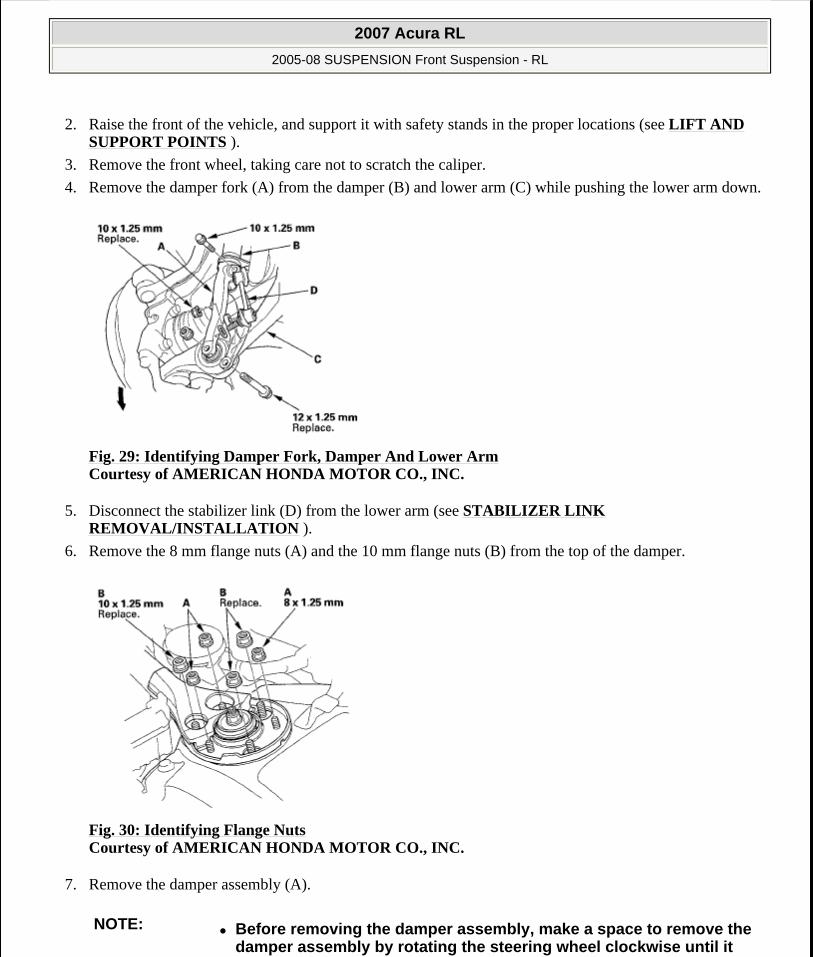
1. Remove the upper fender trims (A) (see UPPER FENDER TRIM REPLACEMENT ).
Fig. 28: Identifying Upper Fender Trims Courtesy of AMERICAN HONDA MOTOR CO., INC.
2007 Acura RL
2005-08 SUSPENSION Front Suspension - RL
me
Friday, June 05, 2009 1:20:39 PM Page 16 © 2005 Mitchell Repair Information Company, LLC.
2. Raise the front of the vehicle, and support it with safety stands in the proper locations (see LIFT AND SUPPORT POINTS ).
3. Remove the front wheel, taking care not to scratch the caliper.
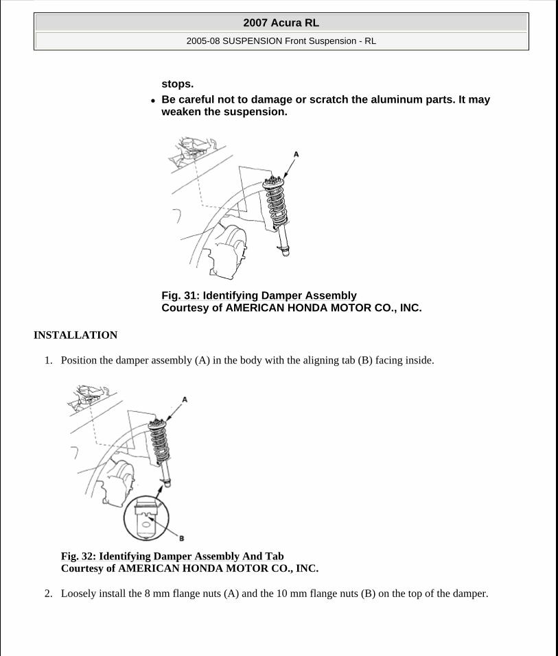
4. Remove the damper fork (A) from the damper (B) and lower arm (C) while pushing the lower arm down.
Fig. 29: Identifying Damper Fork, Damper And Lower Arm Courtesy of AMERICAN HONDA MOTOR CO., INC.
5. Disconnect the stabilizer link (D) from the lower arm (see STABILIZER LINK REMOVAL/INSTALLATION ).
6. Remove the 8 mm flange nuts (A) and the 10 mm flange nuts (B) from the top of the damper.
Fig. 30: Identifying Flange Nuts Courtesy of AMERICAN HONDA MOTOR CO., INC.
7. Remove the damper assembly (A).
NOTE: Before removing the damper assembly, make a space to remove the damper assembly by rotating the steering wheel clockwise until it
2007 Acura RL
2005-08 SUSPENSION Front Suspension - RL
me
Friday, June 05, 2009 1:20:39 PM Page 17 © 2005 Mitchell Repair Information Company, LLC.
INSTALLATION
1. Position the damper assembly (A) in the body with the aligning tab (B) facing inside.
Fig. 32: Identifying Damper Assembly And Tab Courtesy of AMERICAN HONDA MOTOR CO., INC.
2. Loosely install the 8 mm flange nuts (A) and the 10 mm flange nuts (B) on the top of the damper.
stops.
Be careful not to damage or scratch the aluminum parts. It may weaken the suspension.
Fig. 31: Identifying Damper Assembly Courtesy of AMERICAN HONDA MOTOR CO., INC.
2007 Acura RL
2005-08 SUSPENSION Front Suspension - RL
me
Friday, June 05, 2009 1:20:39 PM Page 18 © 2005 Mitchell Repair Information Company, LLC.

Fig. 33: Identifying Flange Nuts With Torque Specifications Courtesy of AMERICAN HONDA MOTOR CO., INC.
3. Install the damper fork (A) over the driveshaft and onto the lower arm while pushing the lower arm down. Install the front damper in the damper fork so the aligning tab (B) is aligned with the slot (C) in the damper fork.
Fig. 34: Identifying Damper Fork With Torque Specifications Courtesy of AMERICAN HONDA MOTOR CO., INC.
4. Loosely install the damper pinch bolt (D) into the damper fork.
5. Install the new flange bolt (E) to the damper fork and lower arm, then lightly tighten the new damper fork mounting nut (F).
6. Install the stabilizer link on the lower arm with the washer and the new self-locking nut, and lightly tighten them.
7. Place the floor jack under the lower arm, and raise the suspension to load it with the vehicle's weight.
2007 Acura RL
2005-08 SUSPENSION Front Suspension - RL
me
Friday, June 05, 2009 1:20:39 PM Page 19 © 2005 Mitchell Repair Information Company, LLC.

8. Tighten the flange nuts on the top of the damper to the specified torque values.
9. Tighten the damper pinch bolt, the flange nut on the damper fork, and self-locking nut to the specified torque value.
10. Clean the mating surfaces of the brake disc and the inside of the wheel, then install the front wheel.
11. Install the upper fender trims (see UPPER FENDER TRIM REPLACEMENT ).
DAMPER/SPRING DISASSEMBLY, INSPECTION, AND REASSEMBLY
EXPLODED VIEW
Fig. 35: Exploded View Of Damper/Spring With Torque Specifications Courtesy of AMERICAN HONDA MOTOR CO., INC.
2007 Acura RL
2005-08 SUSPENSION Front Suspension - RL
me
Friday, June 05, 2009 1:20:39 PM Page 20 © 2005 Mitchell Repair Information Company, LLC.
DISASSEMBLY/INSPECTION
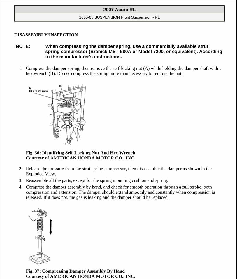
1. Compress the damper spring, then remove the self-locking nut (A) while holding the damper shaft with a hex wrench (B). Do not compress the spring more than necessary to remove the nut.
Fig. 36: Identifying Self-Locking Nut And Hex Wrench Courtesy of AMERICAN HONDA MOTOR CO., INC.
2. Release the pressure from the strut spring compressor, then disassemble the damper as shown in the Exploded View.
3. Reassemble all the parts, except for the spring mounting cushion and spring.
4. Compress the damper assembly by hand, and check for smooth operation through a full stroke, both compression and extension. The damper should extend smoothly and constantly when compression is released. If it does not, the gas is leaking and the damper should be replaced.
Fig. 37: Compressing Damper Assembly By Hand Courtesy of AMERICAN HONDA MOTOR CO., INC.
NOTE: When compressing the damper spring, use a commercially available strut spring compressor (Branick MST-580A or Model 7200, or equivalent). According to the manufacturer's instructions.
2007 Acura RL
2005-08 SUSPENSION Front Suspension - RL
me
Friday, June 05, 2009 1:20:39 PM Page 21 © 2005 Mitchell Repair Information Company, LLC.

5. Check for oil leaks, abnormal noises, and binding during these tests.
REASSEMBLY
1. Align the damper mounting base (A) and spring mounting cushion (B) as shown, then reassemble the damper except for the washer and self-locking nut.
Fig. 38: Identifying Damper Mounting Base And Spring Mounting Cushion Courtesy of AMERICAN HONDA MOTOR CO., INC.
2. Install the damper assembly on a commercially available strut spring compressor (A), and compress the spring lightly.
Fig. 39: Identifying Strut Spring Compressor Courtesy of AMERICAN HONDA MOTOR CO., INC.
3. Align the bottom of the spring and the stepped part (B) of the lower spring seat.
4. Position the damper mounting base (A) so the stud bolt (B) is aligned with the aligning tab (C) in the damper unit as shown.
LEFT:
NOTE: Refer to the EXPLODED VIEW as needed.
2007 Acura RL
2005-08 SUSPENSION Front Suspension - RL
me
Friday, June 05, 2009 1:20:39 PM Page 22 © 2005 Mitchell Repair Information Company, LLC.

RIGHT:
Fig. 40: Identifying Positioning For Damper Mounting Base Courtesy of AMERICAN HONDA MOTOR CO., INC.
5. Compress the damper spring. Do not compress the spring excessively.
6. Install the washer (A) and a new 10 mm self-locking nut (B). Hold the damper shaft with a hex wrench (C), and tighten the 10 mm self-locking nut to the specified torque value.
Fig. 41: Identifying Damper Shaft And Fastener With Torque Specifications Courtesy of AMERICAN HONDA MOTOR CO., INC.
7. Remove the damper assembly from the strut spring compressor.
2007 Acura RL
2005-08 SUSPENSION Front Suspension - RL
me
Friday, June 05, 2009 1:20:39 PM Page 23 © 2005 Mitchell Repair Information Company, LLC.