Embed Size (px)
Citation preview

From Sound to Sight: Using Audio Processing toenable Visible Light Communication
Stefan Schmid∗†, Daniel Schwyn†, Kaan Aksit∗, Giorgio Corbellini∗, Thomas R. Gross†, Stefan Mangold∗
∗Disney Research †Dep. of Computer Science8006 Zurich, Switzerland ETH Zurich, Switzerland
Abstract—Mobile phones can use their cameras and flashlightLight Emitting Diodes (LEDs) to exchange messages with low-complex Visible Light Communication (VLC) networks, butthese interfaces impose serious restrictions when used in a VLCnetwork. In this paper we discuss how to extend mobile phonesor tablets with a small peripheral device that is battery-free,uses only passive components, and offers VLC capabilities atthe required data rate (kilobit per second). This device plugsinto the audio jack; on-board audio signal processing generatesthe outgoing light signals as well as decodes the incoming lightsignals. The device is powered from the phone’s audio jackoutput signal, no additional battery is required. The audio signalsdirectly modulate light emissions of an LED. Incoming light isdetected by a photodiode and the generated electrical signals arefed into the microphone input. This simple device enables use ofexisting communication protocols and therefore makes it possibleto integrate mobile phones or tablets into existing VLC LED-to-LED networks.
I. INTRODUCTION
Visible Light Communication (VLC) with Light Emit-ting Diodes (LEDs) as transceivers enables short range low-bandwidth networking of consumer devices like toys, smart-phones, or tablets. We refer to this use as LED-to-LEDVLC networking [1], [2]. Devices use LEDs to emit lightand transmit data encoded into on-off patterns. The encodingcreates a slotted light pattern that is too fast to be perceived byhuman users (no flickering, typically at 1 kHz or more). Duringthe off periods, the LEDs can be used as photodiodes to senseincoming light, and as a result the LEDs receive data symbolsfrom other LEDs. Earlier papers described the software-basedsynchronization, the data encoding with flicker avoidance, andthe required communication protocols [2].
In this paper we report on the design, implementation andevaluation of a miniature low-cost passive device that can beplugged into an audio jack connection of a mobile phone toenable two-way VLC communication. Figure 1 illustrates howa mobile phone exchanges data with a toy. The device uses anLED and a photodiode to transmit resp. receive signals. Theuse of a photodiode instead of a receiving LED is discussed inSection II-B. When connecting such a device with a phone’sheadset audio jack, the phone can exchange data through lightat a data rate in the order of a kilobit per second in bothdirections. The miniature VLC communication device uses theaudio output of the phone to drive an LED (transmission), andthe microphone input to receive from a photodiode (reception).
The audio jack device is battery-free and operates withoutthe involvement of a microcontroller. The audio signals needed
Fig. 1. (© Disney) VLC enabled toy remotely controlled by a smartphoneextension device plugged into the audio jack.
to modulate the LED are generated by software running onthe phone. The light sensed by the photodiode is also decodedon the phone. The application software running on the phonecan generate data packets in real-time; this capability makes itpossible to run dynamic communication protocols directly onthe phone and enable transmission and reception of data with aperipheral device that uses the LED-to-LED VLC networkingprotocols referred to above.
A. Contributions
In this paper we report the following contributions:
• Hardware design of a VLC peripheral extension devicefor smartphones using the audio jack as interface. Thedevice is battery-free and only powered and operatedthrough audio signals generated by the mobile phone.Further, the device is equipped with a photodiode tofeed incoming modulated light as electrical signalsinto the microphone input (Section II-B).
• Smartphone application software operating the audiojack peripheral device through audio signal processingonly; there is no need for an additional microcon-troller. Microphone input data is analyzed and decodedin software and arbitrary data packets can be generatedin real-time using the peripheral’s LED as a commu-nication front-end (Sections II-C and II-A).
• Evaluation of the designed hardware together withapplication software running on iOS devices; resultsfor different host devices are reported (Section III).

ON OFF ON OFF ON OFF ON OFF
time
G D1 G D2 G S2S1
500μs
ONON
ONOFF
Fig. 2. Slotting structure of the LED-to-LED physical layer network protocol.ON and OFF slots are alternating to provide illumination and communicationat the same time.
B. Related Work
Application scenarios and use cases for VLC-enabledconsumer devices have been demonstrated on several occa-sions [3]–[5]. Smartphones communicating in LED-to-LEDnetworks without the aid of additional devices (using built-in camera and flash light) have also been investigated [6], butthe placement of these building blocks may limit their use insome scenarios. In this paper we extend the smartphone witha peripheral device to increase flexibility, performance, andstability for links between mobile devices and VLC-enabledconsumer devices. Extending smartphones with light sensorsthrough the audio jack interface has also been reported [7].This system, however, allows only a one-way communication(by light) whereas the system described here enables a full-duplex two-way communication. Using a smartphone’s audiojack as communication interface and hardware source has beenextensively investigated by various projects at the Universityof Michigan [8], [9] which provided the foundation for com-mercial hardware developments [10]. The hardware systempresented in this paper is based in part on this approach.
II. SYSTEM
This paper focuses on how to extend smartphones andtablets with VLC functionality. Although these devices arealready equipped with a flash light (light emitter) and camera(light receiver), which can be used for communication [6],[11], they do not provide enough flexibility to work well to-gether with other VLC-enabled devices. Smartphone operatingsystems cannot support real-time scheduling, and control overthe flash light and camera is often restricted. These constraintslimit performance and stability of a VLC link. The systemdescribed in the following sections is based on a passiveperipheral device that plugs into a smartphone’s audio interfaceand can emit and receive light by using the phone’s audiosystem. The peripheral device is battery-free and powered onlythrough the audio signals, yet the communication protocols arehandled without additional micro- or signal- processors – lightis directly modulated through audio signals generated in real-time by the smartphone, and incoming signals are convertedby the microphone and analyzed by application software. Thesystem described can interact with existing VLC-enabled toysor other consumer devices that implement the VLC protocolsdeveloped for LED-to-LED networks, which are summarizedin the following section.
A. LED-to-LED communication protocols
The protocols consist of a physical (PHY) layer andMedium Access Control (MAC) layer [2] based on a software-only implementation for microcontrollers and uses only LEDsas sender and receiver. The PHY layer is not only responsible
for communication but also for illumination. Since an LEDshould always appear (to a human) as switched on, a slottingstructure, illustrated in Figure 2, is introduced. ON and OFFslots are alternating with a period of 500 µs. During an ON slotlight is emitted so that the LED appears as always on. The OFFslots are used to sense incoming light by reverse- biasing theLED [12]. These slots are further divided into smaller intervals(as shown in Figure 2) with the following functions: Thesynchronization slots (S1,S2) in the beginning and at the endare responsible for synchronization to the ON and OFF slotsof a communication partner. The guard intervals (G1,G2,G3)prevent light leakage into the data intervals (D1,D2) in caseof small phase offsets. A zero symbol is encoded as lightemission during D1, and a one symbol is represented by lightemission during D2. The MAC protocol is based on CSMA/CAas applied in the IEEE 802.11 standards and enables contentionbased medium access for a network of VLC devices.
B. Peripheral Device Hardware
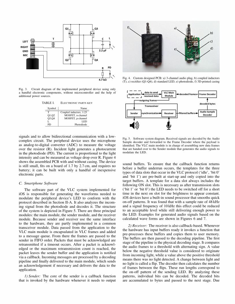
Audio signals are AC-coupled, hence it is not possible todirectly generate an on-off pattern to drive an LED. Further,even with the loudest audio settings, the amplitude of theaudio output signal is still in the millivolts range (around100 mV to 200 mV, depending on the device) and therefore notlarge enough to emit light with reasonable intensity througha standard LED. Our device uses a hardware design that isbased on University of Michigan’s Hijack project [8], [9]. Theschematics of the peripheral device’s Printed Circuit Board(PCB) are shown in Figure 3, and the electronic parts arelisted in Table I. The schematics show a low-complex systemwith only a handful of components, without the need toinclude a microcontroller. The audio signals of the left andright channel are joined together to increase the availablecurrent and therefore also power. This can be seen as twobatteries in parallel but phase-synchronized AC coupled. Thesignals amplitude is increased by the coupled inductors (T,1:25 turns ratio). These inductors are a passive component thatincreases the voltage at the same electric power and thereforealso decreases the current. The transformed signal’s amplitudeprovides high enough voltage to drive an LED. Already withthis raw signal (e.g., shown in Figure 6) the LED emits light,albeit with low intensity. To increase the light emission further,the signal is rectified (Q1-Q4). This step makes it possible toalso use the negative parts of the sine waves to emit lightinstead of reverse biasing the LED. The rectifier is built usingMOSFETs instead of diodes, since diode-based rectifiers sufferfrom power loss (voltage loss of about 0.7 V per diode in path).Finally, a capacitor is used to smooth and stabilize the LED’sinput voltage.
Instead off using exclusively LEDs (i.e., the LED is alsoemployed for reception as described earlier) the device usesa photodiode to convert modulated light back to electricalsignals. Using the same LED to send and receive is not trivialfor this setup. There is a bias voltage of 2 V applied to themicrophone input and therefore, to switch between emittingand receiving light, the LED needs to be attached and detachedfrom and to the microphone line. Such an arrangement intro-duces a difficult problem (if to be solved without microcon-troller). As we aim to keep the hardware as simple as possible,we focus on how to modulate the light with the help of audio
T
RIGHT
GND
MIC
LEFT
PD
L
Q2
Q1
Q4
Q3
C
2.2 µF
R
4.7 k
Fig. 3. Circuit diagram of the implemented peripheral device using onlya handful electronic components, without microcontroller and the help ofadditional power sources.
TABLE I. ELECTRONIC PARTS KEY
Symbol NameT Coupled inductors, 1:25Q1,Q2 MOSFET, n-channelQ3,Q4 MOSFET, p-channelL LEDPD Photodiode
signals and to allow bidirectional communication with a low-complex circuit. The peripheral device uses the microphoneas analog-to-digital converter (ADC) to measure the voltageover the resistor (R). Incident light generates a photocurrentin the photodiode (PD). The current is proportional to the lightintensity and can be measured as voltage drop over R. Figure 4shows the assembled PCB with and without casing. The deviceis still small, fits on a board of 1.7 by 2.7 cm, and requires nobattery; it can be built with only a handful of inexpensiveelectronic parts.
C. Smartphone Software
The software part of the VLC system implemented foriOS is responsible for generating the waveforms needed tomodulate the peripheral device’s LED to conform with theprotocol described in Section II-A. It also analyzes the incom-ing signal from the photodiode and decodes it. The structureof the system is depicted in Figure 5. There are three principalmodules: the main module, the sender module, and the receivermodule. Because sender and receiver use the same interfaceto the hardware, they are partly implemented in a commontransceiver module. Data passed from the application to theVLC main module is encapsulated in VLC frames and addedto a message queue. From there the frames are passed to thesender in FIFO order. Packets that must be acknowledged areretransmitted if a timeout occurs. After a packet is acknowl-edged or the maximum retransmission count is reached, thepacket leaves the sender buffer and the application is notifiedvia a callback. Incoming messages are processed by a decodingpipeline and finally delivered to the main module, which sendsan acknowledgement if necessary and delivers the data to theapplication.
1) Sender: The core of the sender is a callback functionthat is invoked by the hardware whenever it needs to output
Fig. 4. Custom designed PCB: a) 3-channel audio plug, b) coupled inductors(T), c) rectifier (Q1-Q4), d) standard LED, e) photodiode, f) 3D-printed casing
ApplicationVLC Main Module
Sender ReceiverAudio Sample
Decoder
Frame Decoder
synchronization filtered buffers
decoded bytes
decoded frames
outgoing frames
data to send
received data
Fig. 5. Software system diagram. Received signals are decoded by the AudioSample decoder and forwarded to the Frame Decoder where the payload isidentified. The VLC main module is in charge of assembling new data framesthat are handed over to the Sender module that generates the audio signals tomodulate the LED.
sound buffers. To ensure that the callback function returnsbefore a buffer underrun occurs, the templates for the threetypes of data slots that occur in the VLC protocol (‘idle’, ‘bit 0’and ‘bit 1’) are pre-built at start-up and only copied into thetarget buffers. A template for a data slot always includes thefollowing ON slot. This is necessary as after transmission slots(‘bit 1’ or ‘bit 0’) the LED needs to be switched off for a shorttime in the next on slot for the brightness to appear constant.iOS devices have a built-in sound processor that smooths quickon-off patterns. It was found that with a sample rate of 48 kHzand a signal frequency of 10 kHz this effect could be reducedto an acceptable level while still delivering enough power tothe LED. Examples for generated audio signals based on thecalculated wave forms are shown in Figures 6 and 7.
2) Receiver: The receiver is also callback-based. Wheneverthe hardware has input buffers ready it invokes a function thatpre-processes these buffers and copies them to user memory.The buffers are then passed to the decoding pipeline. The firststage of the pipeline is the physical decoding stage. It comparesthe audio frames to a threshold with alternating sign. A valuebelow the negative threshold value is considered to originatefrom incoming light, while a value above the positive thresholdmeans there was no light detected. A change between light andno light is called a flip. The decoder then calculates the numberof frames between the flips. These run lengths correspond tothe on-off pattern of the sending LED. By analyzing thesepatterns, individual bits can be decoded. The decoded bitsare accumulated to bytes and passed to the next stage. Due

ON OFF ON OFF ON OFF ON
500μs
OFFOFF
Fig. 6. Stereo audio signal generated by the smartphone’s audio system toproduce an ON-OFF emission pattern with the LED.
500μs
ON OFF ON OFF ON OFFOFF ON
D DDDC C C C
Fig. 7. Stereo audio signal during the transmission of a data packet. Thesignal is switched on earlier or stays on longer to provide light for a dataslot at the beginning or in the end of an OFF slot (D). To compensate theadditional light output to avoid flickering, the audio signal is switched OFFduring the following ON slot (C). To ease reading the figure, an ON-OFFlegend is shown.
to a high level of noise in the signal (see Section II-C3),short intervals cannot be reliably detected with a resolutionof only 24 frames per slot (due to the maximum sample rateof iOS devices at 48 kHz). Thus the VLC decoding schemefrom Figure 2 needs to be simplified in the following way(see also Table II): If there is no flip during the OFF slot,no bit is detected. If there is a flip, to distinguish betweenbits, the decoder detects in which half of the OFF slot a runlength above the positive threshold exists for about 13 framesand assumes the spike to encode the symbol appears in theother half. Furthermore, the inability to detect short intervalsprevents the system from being able to synchronize to anotherVLC device (as it cannot detect the synchronization intervalsillustrated in Figure 2). As long as only one smartphone isin a network, this limitation does not pose a problem as theother VLC devices can synchronize to the smartphone’s on-off pattern. The second pipeline stage decodes the protocolframes. The decoding process works the same as for LED-to-LED networks [2]: After a Start Frame Delimiter (SFD) isdetected, the headers are decoded and the CRC is calculated.The decoded frames are then passed to the main module.
3) Signal feedback: Because of the simple circuitry thatis included in the peripheral device, the device suffers fromsignal leaks into the receiver. This poses two problems: First,there is a 10 kHz feedback signal during ON slots. It was foundthat this makes it impossible to reliably detect the end of ONslots as the wavelength of this signal is inside the toleranceinterval for GUARD1.
TABLE II. DECODING PATTERNS
Interval # frames idle bit 0 bit 1GUARD1 5 OFF OFF OFFDATA1 6 OFF ON OFFGUARD2 2 OFF OFF OFFDATA2 6 OFF OFF ONGUARD3 5 OFF OFF OFF
Fig. 8. Signals as received by the Audio Sample Decoder. The dashed (red)line indicates the run length pattern found. a) Receiving with sender off; b)Receiving with sender on; c) Receiving with ON slots filtered; d) Sending –only ON slots filtered; e) Sending – ON and OFF slots filtered.
Second, if the sender is active, the spikes in the data slotsthat encode the symbols are also fed back to the receiver.This also leads to the decoder losing synchronization with theslot pattern. To prevent both of the problems the buffers arepreprocessed directly in the hardware callback: By keepingtrack of the OFF slot sample times in the sender callback, thecorresponding incoming buffers are set to a value below thenegative threshold to mark them as ON. Similarly the bufferscorresponding to data slots where the sender is active are set toa value above the positive threshold to mark them as OFF. AsOFF slots do not carry information and an incoming messagein the same slots as an outgoing would lead to a collisionanyway we lose no information this way. Figure 8 shows thesignals received by the Audio Sample Decoder.
4) Multithreading: To enable asynchronism and increaseperformance, the system uses multi-threading. With GrandCentral Dispatch (GCD) iOS offers an easy to use framework:Blocks of code can be dispatched to serial queues (serial meansthe queue operates in a FIFO manner). The system then takescare of the mapping of these queues to an suitable number ofworker threads. In the main module there are two serial queues,one that handles incoming messages and one that dispatchespackets from the message queue to the sender. Furthermoreeach stage of the decoding pipeline runs on its own serialqueue.
III. EVALUATION
The evaluation is conducted with a testbed consisting ofan iPhone 5S and an iPad mini (both equipped with Apple’sA7 processor, running iOS 7) and a VLC device running theprotocols (on an Atmel microcontroller [13]) described in Sec-tion II-A that uses only an LED as transceiver. The audio jackperipheral device is platform-independent. Other smartphonesor tablets, even laptops or desktop computers (independent ofoperating systems), could be used for this evaluation as longas they provide a 3-channel audio jack plug with a matchingpinout. We focus on Apple’s iOS devices because of the welldocumented audio API. All experiments are conducted in astandard office space without special shielding from artificiallight and sunlight.
A. ACK timeout
The VLC device and smartphone both run a MAC layercapable for data frame acknowledgments and retransmissions.After transmitting a data frame, the transmitter waits for theACK timeout. If no ACK from the data frame’s destinationis received within this interval, the frame counts as lost andthe transmitter retransmits. This procedure is repeated until anACK reaches the sender or a fixed number of retransmissionshas happened. The firmware running on the VLC device’smicrocontroller is real-time and the ACK timeout can be keptsmall since a receiving device is fast in processing a receiveddata frame and transmitting an ACK (within few milliseconds).A short ACK timeout guarantees higher throughput perfor-mance for a network consisting of only a few devices, as thecommunication channel can be used more efficiently.
A smartphone operating system is not a system with real-time guarantees and the main processor is used for severaldifferent tasks at the same time. Also, it may take some timeto analyze incoming data from the audio jack and decode thedata packet. Further the audio signals needed to transmit anACK are generated on demand specifically for the receiveddata frame; this step takes additional time. Therefore the ACKtimeout of the VLC device must be adjusted to enable asuccessful and optimized data exchange with a smartphoneusing the audio jack extension device.
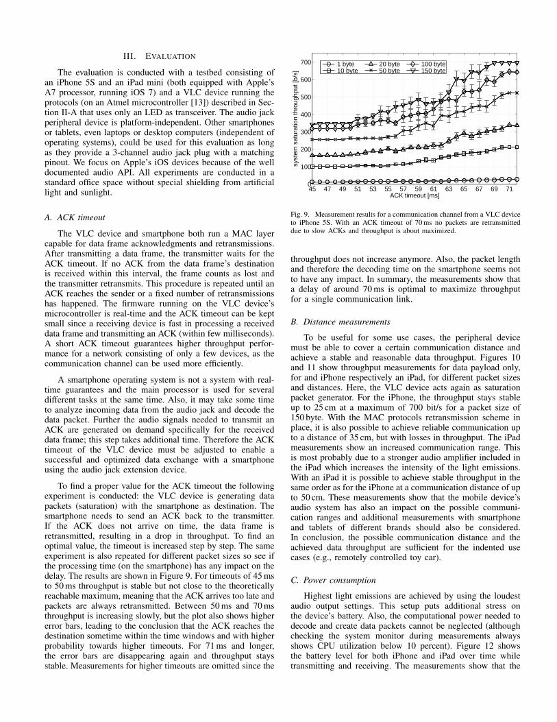
To find a proper value for the ACK timeout the followingexperiment is conducted: the VLC device is generating datapackets (saturation) with the smartphone as destination. Thesmartphone needs to send an ACK back to the transmitter.If the ACK does not arrive on time, the data frame isretransmitted, resulting in a drop in throughput. To find anoptimal value, the timeout is increased step by step. The sameexperiment is also repeated for different packet sizes so see ifthe processing time (on the smartphone) has any impact on thedelay. The results are shown in Figure 9. For timeouts of 45 msto 50 ms throughput is stable but not close to the theoreticallyreachable maximum, meaning that the ACK arrives too late andpackets are always retransmitted. Between 50 ms and 70 msthroughput is increasing slowly, but the plot also shows highererror bars, leading to the conclusion that the ACK reaches thedestination sometime within the time windows and with higherprobability towards higher timeouts. For 71 ms and longer,the error bars are disappearing again and throughput staysstable. Measurements for higher timeouts are omitted since the
45 47 49 51 53 55 57 59 61 63 65 67 69 710
100
200
300
400
500
600
700
ACK timeout [ms]
syst
em s
atur
atio
n th
roug
hput
[b/s
]
1 byte10 byte
20 byte50 byte
100 byte150 byte
Fig. 9. Measurement results for a communication channel from a VLC deviceto iPhone 5S. With an ACK timeout of 70 ms no packets are retransmitteddue to slow ACKs and throughput is about maximized.
throughput does not increase anymore. Also, the packet lengthand therefore the decoding time on the smartphone seems notto have any impact. In summary, the measurements show thata delay of around 70 ms is optimal to maximize throughputfor a single communication link.
B. Distance measurements
To be useful for some use cases, the peripheral devicemust be able to cover a certain communication distance andachieve a stable and reasonable data throughput. Figures 10and 11 show throughput measurements for data payload only,for and iPhone respectively an iPad, for different packet sizesand distances. Here, the VLC device acts again as saturationpacket generator. For the iPhone, the throughput stays stableup to 25 cm at a maximum of 700 bit/s for a packet size of150 byte. With the MAC protocols retransmission scheme inplace, it is also possible to achieve reliable communication upto a distance of 35 cm, but with losses in throughput. The iPadmeasurements show an increased communication range. Thisis most probably due to a stronger audio amplifier included inthe iPad which increases the intensity of the light emissions.With an iPad it is possible to achieve stable throughput in thesame order as for the iPhone at a communication distance of upto 50 cm. These measurements show that the mobile device’saudio system has also an impact on the possible communi-cation ranges and additional measurements with smartphoneand tablets of different brands should also be considered.In conclusion, the possible communication distance and theachieved data throughput are sufficient for the indented usecases (e.g., remotely controlled toy car).
C. Power consumption
Highest light emissions are achieved by using the loudestaudio output settings. This setup puts additional stress onthe device’s battery. Also, the computational power needed todecode and create data packets cannot be neglected (althoughchecking the system monitor during measurements alwaysshows CPU utilization below 10 percent). Figure 12 showsthe battery level for both iPhone and iPad over time whiletransmitting and receiving. The measurements show that the

5 10 15 20 25 30 35 40 45 50 550
100
200
300
400
500
600
700
distance [cm]
syst
em s
atur
atio
n th
roug
hput
[b/s
]
1 byte10 byte20 byte
50 byte100 byte150 byte
Fig. 10. Measurement results for a communication channel from a VLCdevice to iPhone 5S. Larger packet sizes result in higher throughput due tosmaller protocol overhead. The system operates reliably up to 25 cm.
5 10 15 20 25 30 35 40 45 50 550
100
200
300
400
500
600
700
distance [cm]
syst
em s
atur
atio
n th
roug
hput
[b/s
]
1 byte
10 byte
20 byte
50 byte
100 byte
150 byte
Fig. 11. Measurement results for a communication channel from a VLCdevice to iPad mini. The useful distance is increased by 20 cm compared tothe iPhone 5S.
battery lifetime is more than four hours for the iPhone, andmore than five hours for the iPad (due to higher batterycapacity). If we assume that the audio jack peripheral deviceis not used more than 10% of the overall usage time, then theperipheral device does not impact battery lifetime significantly.
IV. CONCLUSION
This paper reports on the design, implementation andevaluation of a smartphone VLC extension device. It uses thephone’s audio jack as interface and is operated by audio signalprocessing. The key design constraints were low-complexity,low-cost, battery-free operation, and interoperability with ex-isting VLC systems. A simple and passive plug-in device ispresented based on only a handful of electronic componentspowered buy audio signals. Its LED is modulated withoutthe help of an additional microcontroller, directly by audiosignals generated in real-time by the application. Evaluationresults demonstrate that the VLC protocols implemented insoftware on the smartphone or tablet provide stable and reliablecommunication over distances from 25 cm to 50 cm dependingon the device used (and its audio system). These results show
0:00 0:30 1:00 1:30 2:00 2:30 3:00 3:30 4:00 4:30 5:00 5:300%
10%
20%
30%
40%
50%
60%
70%
80%
90%
100%
time [h:min]
batte
ry le
vel
iPhone 5S iPad mini
Fig. 12. Battery lifetime for iPhone and iPad mini. Sender idle, screen turnedon. Battery life does not pose a problem for common use cases.
that smartphones or tablet can now be integrated into existingVLC networks by the addition of this small passive component.
REFERENCES
[1] S. Schmid, G. Corbellini, S. Mangold, and T. Gross, “An LED-to-LEDVisible Light Communication System with Software-based Synchro-nization,” in Optical Wireless Communication. Globecom Workshops(GC Wkshps), 2012 IEEE, Dec. 2012, pp. 1264–1268.
[2] ——, “LED-to-LED Visible Light Communication Networks,” in Mo-biHoc, 2013 ACM, Aug. 2013.
[3] S. Schmid, M. Gorlatova, D. Giustiniano, V. Vukadinovic, and S. Man-gold, “Networking Smart Toys with Wireless ToyBridge and ToyTalk,”in Poster Session, Infocom, 2011.
[4] G. Corbellini, S. Schmid, S. Mangold, T. R. Gross, and A. Mkrtchyan,“LED-to-LED Visible Light Communication for Mobile Applications,”in Demo at ACM SIGGRAPH Mobile 2012, Aug. 2012.
[5] S. Schmid, J. Ziegler, T. R. Gross, M. Hitz, A. Psarra, G. Corbellini, andS. Mangold, “(In)visible light communication: Combining illuminationand communication,” in ACM SIGGRAPH 2014 Emerging Technologies,ser. SIGGRAPH ’14, 2014.
[6] G. Corbellini, K. Aksit, S. Schmid, S. Mangold, and T. R. Gross,“Connecting networks of toys and smartphones with visible lightcommunication,” IEEE Communications Magazine, vol. 52, no. 7, pp.72–78, 2014.
[7] Luicom. (2014) Luciom, presentation at International CES in LasVegas. 10-July-2014. [Online]. Available: http://www.luciom.com/fr/actus/ces-las-vegas-nevada-us-7-10-janvier-2014
[8] Michigan University. (2014) Project Hijack. 10-July-2014. [Online].Available: http://web.eecs.umich.edu/∼prabal/projects/hijack/
[9] Y.-S. Kuo, S. Verma, T. Schmid, and P. Dutta, “Hijacking power andbandwidth from the mobile phone’s audio interface,” in Proceedingsof the First ACM Symposium on Computing for Development, ser.ACM DEV ’10. New York, NY, USA: ACM, 2010, pp. 24:1–24:10.[Online]. Available: http://doi.acm.org/10.1145/1926180.1926210
[10] NXP Semiconductors. (2014) Smartphone Quick-Jack. 10-July-2014. [Online]. Available: http://www.lpcware.com/content/project/smartphone-quick-jack-solution
[11] C. Danakis, M. Afgani, G. Povey, I. Underwood, and H. Haas, “Usinga cmos camera sensor for visible light communication,” in GlobecomWorkshops (GC Wkshps), 2012 IEEE, Dec 2012, pp. 1244–1248.
[12] P. Dietz, W. Yerazunis, and D. Leigh, “Very Low-Cost Sensingand Communication Using Bidirectional LEDs,” in UbiComp 2003:Ubiquitous Computing, vol. 2864, 2003, Book Section, pp. 175–191.[Online]. Available: http://dx.doi.org/10.1007/978-3-540-39653-6 14
[13] Atmel, “8-bit Microcontroller with 4/8/16/32KBytes In-System Pro-grammable Flash,” www.atmel.com, 2012.