Embed Size (px)
Citation preview

From s/n: 19461To s/n: 20590
From s/n: 19260To s/n: 20669

Operator’s Manual
2 GTH-4010 SX - GTH-3512 SX Part No. 57.0009.0458
First Edition - Third Printing
Contact us:ZONA INDUSTRIALE I-06019 UMBERTIDE (PG) - ITALYTelephone +39 075 941811 - Telefax +39 075 9415382
Technical Assistance ServiceTelephone: +39 075 9418129 +39 075 9418171e-mail: [email protected]
ImportantRead, understand and obey these safety rules and operating instructions before operating the machine. Only trained and qualified personnel shall be authorized to operate the machine. This manual shall be kept with the machine at all times.
For any further information, please call Terexlift.
Contents
Introduction ..........................................Page 3Machine Identification ..........................Page 5Symbols Used On The Machine ..........Page 7Labels And Plates Applied On The Machine ...............................................Page 9Safety Precautions ..............................Page 15 Description Of The Main Components ...Page 23 Controls And Instruments ....................Page 25 Inspections ..........................................Page 41 Operating Instructions .........................Page 45 Transporting The Machine...................Page 59 Maintenance ........................................Page 63Faults And TroubleshootingFaults And Troubleshooting..................................Page 93Page 93Optional Attachments ..........................Page 97 Specifications ......................................Page 109 Load Charts .........................................Page 111 Diagrams And Schemes ......................Page 135Warranty ..............................................Page 147
First Edition: Third Printing, Febraury 2009
Copyright © 2008 TEREXLIFT srl - All rights reserved.
Produced by: TEREXLIFT Technical Literature Dept.Umbertide (PG) Italy
Part No. 57.0009.0458 GTH-4010 SX - GTH-3512 SX 3
Operator’s ManualFirst Edition - Third Printing
Introduction
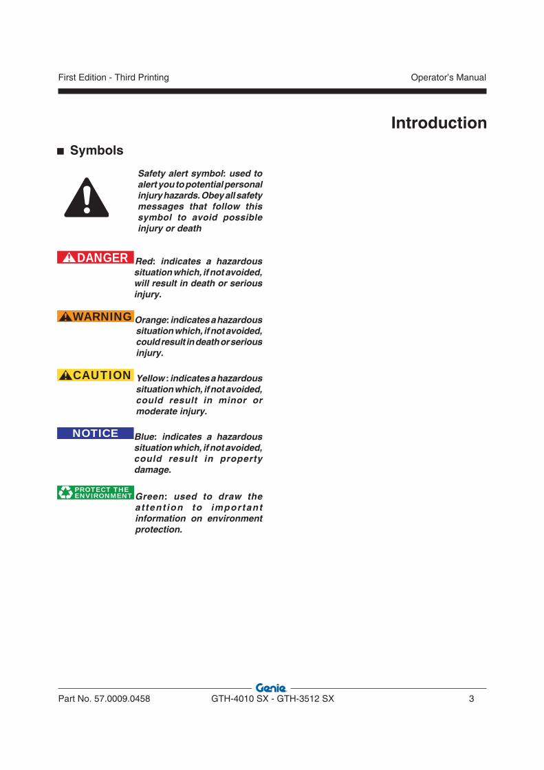
Symbols
Safety alert symbol: used to alert you to potential personal injury hazards. Obey all safety messages that follow this symbol to avoid possible injury or death
DANGER Red: indicates a hazardous situation which, if not avoided, will result in death or serious injury.
WARNING Orange: indicates a hazardous situation which, if not avoided, could result in death or serious injury.
CAUTION Yellow : indicates a hazardous situation which, if not avoided, could result in minor or moderate injury.
NOTICE Blue: indicates a hazardous situation which, if not avoided, could result in property damage.
PROTECT THEENVIRONMENT Green: used to draw the
a t tent ion to important information on environment protection.

Operator’s Manual
4 GTH-4010 SX - GTH-3512 SX Part No. 57.0009.0458
First Edition - Third Printing
Intentionally blank page
Part No. 57.0009.0458 GTH-4010 SX - GTH-3512 SX 5
Operator’s ManualFirst Edition - Third Printing
Machine Identification
Check that the operator handbook refers to the delivered machine.
MODEL AND TYPEHandler with telescopic boom:
models: GTH-4010 SX - GTH-3512 SX
MANUFACTURER
TEREXLIFT srlZona Industriale - I-06019 UMBERTIDE (PG) - ITALY
Enrolled in the register of companies at the Court of Perugia under no. 4823
C.C.I.A.A. 102886
Fiscal Code/V.A.T. no. 00249210543
APPLICABLE STANDARDSFor the operator’s safety, the following standards were obeyed during the risk assessment of the handler fitted with telescopic boom norme:
Directive Title
98/37/CE Machinery Directive
89/336/CEE Electromagnetic compatibility
2000/14/CE Environment Acoustic Emissions
Standard Title
EN 1459:1988 Harmonised standard. Safety of industrial trucks - Self- propelled variable reach trucks.
EN 281:1988 Self-propelled industrial trucks sit- down rider-controlled. Rules for the construction and layout of pedals.
EN 1175-2:1998 Electrical requirements - General requirements of internal combustion engine powered trucks.
ISO 2330:1995 Fork-lift trucks - Fork arms - Technical characteristics and testing.
ISO 3287: 1999 Powered industrial trucks - Symbols for operator controls.
ISO 3449:1992 Earth-moving machinery - Falling-object protective structures - Laboratory tests and performance requirements.
EN 13510: 2002 Earth-moving machinery - Roll-over protective structures - Laboratory tests and performance requirements.
ISO 6292:1996 Powered industrial trucks and tractors - Brake performance and component strength.
EN 13059:2002 Safety of Industrial trucks- Test methods for measuring vibration
ISO 2867:1994 Earth-moving machinery - Access systems
EN ISO 6683:2005 Earth-moving machinery - Seat belts and seat belt anchorages - Performance requirements and tests
ISO 11112: 1995 Earth-moving machinery -
+ AMD 1: 2001 Operator’s seat - Dimensions and requirements
MACHINE IDENTIFICATION PLATES
The following data plates are applied on the machine:
Machine data plateThe identification plate contains the main identification data of the machine like model, serial number and year of manufacture.
On machines destined for the Italian market, the data plate is installed in the driving cab, on the right, and is well-visible when the door is opened. On the machines destined for foreign markets, the data plate is applied on the front right side of the chassis.

Operator’s Manual
6 GTH-4010 SX - GTH-3512 SX Part No. 57.0009.0458
First Edition - Third Printing
Machine Identification
Road traffic data plateThe road traffic data plate is installed on the front right side of the chassis (only on machines destined for the Italian market).This plate shows the road traffic related data and the weights of the specific machine model.
ROPS-FOPS cab type-approval plateThe ROPS - FOPS type-approval plate is located inside the driving cab above the rear glass.
Fork data platePlaced on the left side of the fork frame.
This plate shows the identification data of fork such as model, serial number, year of manufacture, weight, nominal payload, centre of the load and model of the machine on which the forks are installed.
CE MARKINGThis machine fulfils the safety requirements of the Machinery Directive.The conformity has been certified and the placing of the CE marking on the machine demonstrates compliance with the regulatory requirements.The CE marking is placed directly on the identification plate of the machine.
CHASSIS SERIAL NUMBERThe chassis serial number is punched on the front left part of the chassis side member.
IDENTIFICATION PLATES OF THE MAIN PARTSThe plates of the main components, not directly manufactured by TEREXLIFT srl (for instance, engines, pumps, etc.), are located where originally applied by the manufacturers.
HOW TO READ YOUR SERIAL NUMBER
Chassis serial number(The chassis serial number is punched on the front left part of the chassis side member)
Machine data plate(On machines destined for the Italian market, the machine data plate is installed in the driving cab, on the right, and is well-visible when the door is opened. On the machines destined for foreign markets, the data plate is applied on the front right side of the chassis)
GTH-3512 P 07 17882
MODEL
ENGINETYPE
YEAR OFMANIFACTURER
SERIAL NUMBER

Part No. 57.0009.0458 GTH-4010 SX - GTH-3512 SX 7
Operator’s ManualFirst Edition - Third Printing
Symbols Used On The Machine
Fuel Level Brake pressure Fog lamp Parking Brake Battery Charge
Low Engine Oil Pressure
Hydraulic Oil Filter Clogged
Low Hydraul ic Oi l Level
Turn Signals High Beam
Hydraulic Oil Temperature Indicator
Air Filter Restricted Glow Plugs Preheating High Coolant Tempe-rature
Low Beam
Steering Mode Cab Ventilation Fan Transfer Mode Hazard Warning Lights Position Lights
Fuel Cap Hydraulic Oil Lift Point
09.4618.0916
09.4618.0917 09.4618.0928

Operator’s Manual
8 GTH-4010 SX - GTH-3512 SX Part No. 57.0009.0458
First Edition - Third Printing
Symbols Used On The Machine
HAZARD PICTORIAL DESCRIPTIONS
Crush HazardSupport boom when performing maintenance.
No riders.
Fall HazardMaintain required clearance.
ElectrocutionHazard
No people under load.
Falling Object Hazard
Read the operator's manual.
Burn Hazard
Burn Hazard
Explosion/Burn Hazard
No smoking. No open flame.
Allow system to cool.
Allow surfaces to cool.
Crush HazardKeep away from moving parts. Crush Hazard
Keep clear of moving parts.
Allow compartment access
Crush Hazard Keep clear of moving outriggers.

Part No. 57.0009.0458 GTH-4010 SX - GTH-3512 SX 9
Operator’s ManualFirst Edition - Third Printing
Labels And Plates Applied On The Machine
3
3
4 5
5
6
7
16
9
11 12
13
14
14
18
19
20
2425
2526
28
31
33
C
B
30
1
2
3
3
4 4
5
5
8
9
10
13
14 14
14
15
17
18 21
22
23
25
27
27
25
29
32
34
D
A
35

Operator’s Manual
10 GTH-4010 SX - GTH-3512 SX Part No. 57.0009.0458
First Edition - Third Printing
Labels And Plates Applied On The Machine
Use the pictures on these pages to verify that all decals are legible and in place.The following chart shows quantities and description too.
Ref. Decal Code Description Qt.
1 09.4618.0791 Safety pin operation 1
2 09.4618.0784The capacity of the truck and attachment combination shall be complied with.
1
3 09.4618.0547 Tyre inflat. P=5.5bar/80psi 4
4 09.4618.0918 Falling Object Hazard 3
5 09.4618.0919 Crush Hazard 4
6 09.4618.0563 Guaranteed sound power level 1
7 09.4618.0920 Compartment Access 1
809.4616.0040
09.4616.0006
Max Capacity for GTH-4010 SX
Max Capacity for GTH-3512 SX
1
1
WORKING POSITION STORAGE POSITIONSAFETY PIN
09.4618.0791
P= 5.5 bar 80 psi
Use the pictures on these pages to verify that all decals are legible and in place.The following chart shows quantities and description too.
10209.4618.0563
Kg 4000Kg 3500
09.4618.0918
09.4618.0919
09.4618.0920
Part No. 57.0009.0458 GTH-4010 SX - GTH-3512 SX 11
Operator’s ManualFirst Edition - Third Printing
Labels And Plates Applied On The Machine
Ref. Decal Code Description Qt.
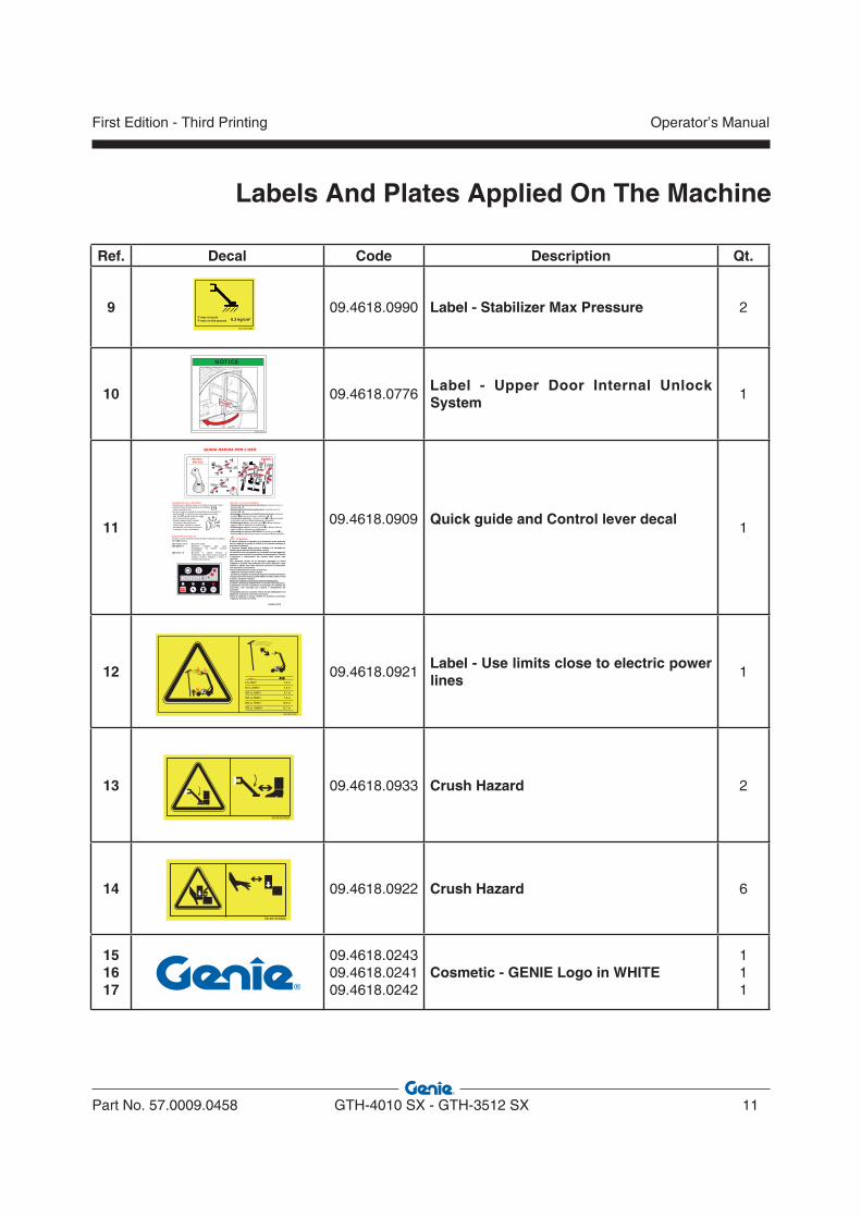
9 09.4618.0990 Label - Stabilizer Max Pressure 2
10 09.4618.0776Label - Upper Door Internal Unlock System
1
1109.4618.0909 Quick guide and Control lever decal
1
12 09.4618.0921Label - Use limits close to electric power lines
1
13 09.4618.0933 Crush Hazard 2
14 09.4618.0922 Crush Hazard 6
151617
09.4618.024309.4618.024109.4618.0242
Cosmetic - GENIE Logo in WHITE111
09.4618.0776
NOTICE
USO DELLA LEVA DI COMANDO• Abbassamento/sollevamento del braccio: azionare la leva in
direzione - • Richiamo/sfilo del braccio telescopico: azionare la leva in
direzione - • Brandeggio indietro/avanti dell’attrezzo terminale: premere il
pulsante ed azionare la leva in direzione -• Livellamento macchina: azionare la leva in per sollevare il lato destro oppure in per abbassare il lato destro• Stabilizzatore destro: azionare la leva in per sollevare oppure in per abbassare lo stabilizzatore• Stabilizzatore sinistro: azionare la leva in per sollevare oppure in per abbassare lo stabilizzatore• Blocco/sblocco attrezzi (OPZIONALE): azionare la leva in
direzione per bloccare gli attrezzi, in direzione per sbloccarli
ATTENZIONEÈ vietato utilizzare la macchina e gli accessori senza prima aveletto e compreso le norme di utilizzo e di sicurezza contenute nemanuale di istruzioni.Il mancato rispetto delle norme di utilizzo e di sicurezza pucausare grave pericolo all’operatore e a terzi.Le istruzioni sono consegnate con la macchina e copie aggiuntivpossono esere richieste al rivenditore o direttamente a Terexlift.L’operatore è responsabile del rispetto delle norme soprriportate.Non sollevare carichi se la macchina appoggia su terreninstabile o inclinato. Non sollevare mai carichi superiori a quelindicati in tabella. Non sono ammesse manovre di sollevamentcon macchina in movimento.Prima di abbandonare il posto di manovra:- abbassare eventuali carichi sospesi- portare in posizione di riposo gli organi di comando del braccio-posizionare la leva marcia avanti-indietro in folle, inserire il frena mano e arrestare il motore.Norme per l’utilizzo di macchine dotate di stabilizzatori:È vietato utilizzare gli stabilizzatori se il carico è già sollevato: gstabilizzatori servono solamente ad aumentare la stabilità dellmacchina; l’uso scorretto può causare il ribaltamento dellmacchina.Un’apposita spia sul cruscotto indica che gli stabilizzatori sonabbassati: accertarsi che la spia sia accesa.Prima di sollevare il carico, livellare la macchina controllandl’apposito indicatore di livello.
09.4618.0713
AVVIAMENTO DELLA MACCHINA• Posizionare il selettore marce ed il cambio meccanico in folle.• Inserire il freno di stazionamento e controllare
che sia accesa la spia • Avviare il motore ruotando il commutatore di avviamento in
posizione e mantenero fino allo spegnimento della spia. Ruotarlo quindi in posizione per l’avviamento del motore.• Qualora, dopo circa 20 secondi,
l’avviamento del motore non avesse luogo, rilasciare la chiave ed attendere circa due minuti primadi tentare un nuovo avviamento.
INDICATORE DI STABILITA’Durante il lavoro mantenere sotto controllo l‘indicatore di stabilità.Gli 8 LED indicano:
Macchina stabile.Macchina instabile. Spia rossa lampeggiante ed allarme acustico intermittente.Macchina in allarme. Pericolo di ribaltamento. Spia rossa accesa ed allarme acustico continuo. Eseguire il rientro in condizioni di sicurezza.
LED verdi 1-2-3-4LED gialli 5-6
LED rossi 7-8
GUIDA RAPIDA PER L’USO
OPTIONAL
5
4013sx - 4017sx
2
1
22
3
4
09.4618.0921
09.4618.0922
09.4618.0989
P max al suoloP max on the ground 6.3 kg/cm2
09.4618.0933
Operator’s Manual
12 GTH-4010 SX - GTH-3512 SX Part No. 57.0009.0458
First Edition - Third Printing
Ref. Decal Code Description Qt.
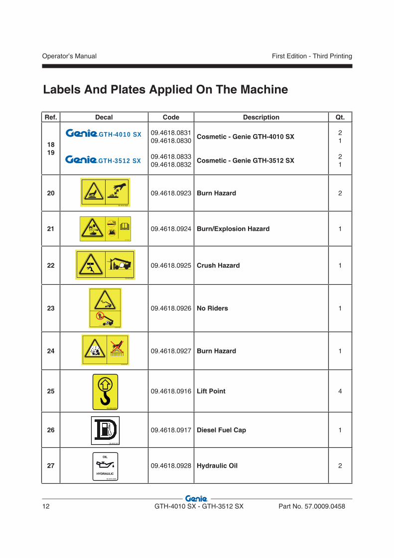
1819
09.4618.083109.4618.0830
09.4618.083309.4618.0832
Cosmetic - Genie GTH-4010 SX
Cosmetic - Genie GTH-3512 SX
21
21
20 09.4618.0923 Burn Hazard 2
21 09.4618.0924 Burn/Explosion Hazard 1
22 09.4618.0925 Crush Hazard 1
23 09.4618.0926 No Riders 1
24 09.4618.0927 Burn Hazard 1
25 09.4618.0916 Lift Point 4
26 09.4618.0917 Diesel Fuel Cap 1
27 09.4618.0928 Hydraulic Oil 2
GTH-4010 SX
09.4618.0923
09.4618.0925
09.4618.0926
09.4618.0927
09.4618.0916
09.4618.0924
09.4618.0917
09.4618.0928
GTH-3512 SX
Labels And Plates Applied On The Machine
Part No. 57.0009.0458 GTH-4010 SX - GTH-3512 SX 13
Operator’s ManualFirst Edition - Third Printing
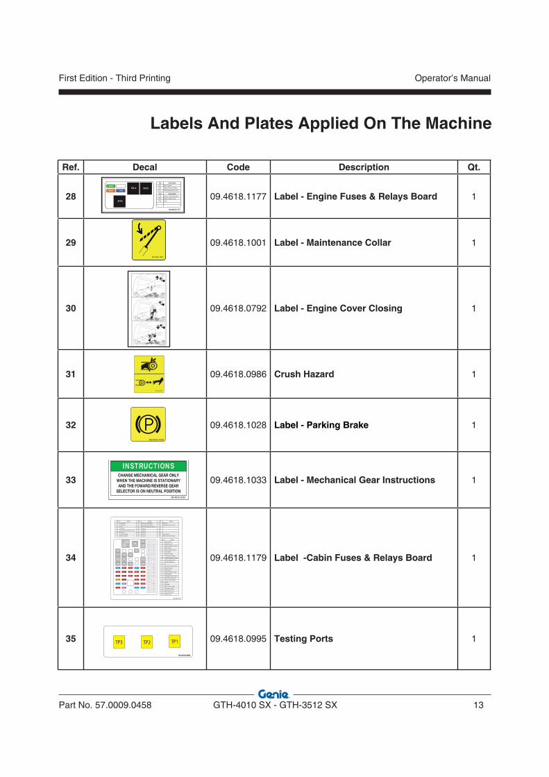
Ref. Decal Code Description Qt.
28 09.4618.1177 Label - Engine Fuses & Relays Board 1
29 09.4618.1001 Label - Maintenance Collar 1
30 09.4618.0792 Label - Engine Cover Closing 1
31 09.4618.0986 Crush Hazard 1
32 09.4618.1028 Label - Parking Brake 1
33 09.4618.1033 Label - Mechanical Gear Instructions 1
34 09.4618.1179 Label -Cabin Fuses & Relays Board 1
35 09.4618.0995 Testing Ports 1
INSTRUCTIONSCHANGE MECHANICAL GEAR ONLY
WHEN THE MACHINE IS STATIONARY AND THE FOWARD/REVERSE GEAR
SELECTOR IS ON NEUTRAL POSITION09.4618.1033
Labels And Plates Applied On The Machine
09.4618.1177
F1G F4GRL1 K02
F2G F3G
K01F5G
Ref. Description
F1G Starter Enabling Switch
F2G Engine Ignition Key
F3G Horn
Ref. Description
K01 Start Engine
K02 Signal Reverse Relay
RL1 Preheating Control Unit
09.4618.1001
09.4618.0986
K1
K9
K4
K11
K3
K21
K14
K18
F22
F23
F24
F25
F26
F27
F16
F17
F18
F19
F20
F21
F13
F14
F15
F7
F8
F9
F10
F11
F12
F1
F2
F3
F4
F5
F6
K19K23
J3 J2 J1
K8
K7
K10
K2
K24
09.4618.1179
.feR Circuit
F1 Front Wiper
F2 Heating - A/C
F3 Stop Light Micro-Switch
F4 Rear Wiper
F5 Road Jobsite Switch
F6 Low Beam
F7 Position Lights
F8 Instrument Lighting
F9 Indicator Lights Power Supply
F10 Road Lights Switch
F11 Flashing Beacon
F12 ---------
F13 2° Hydr. Circuit Switch
F14 Speed Switch
F15 High Beam
F16 Hazard Warning Light
F17 Road Lights
F18 Outriggers Micro-Switch
F19 Work Mode Selector
F20 +12v On The Boom
F21 Horn
F22 Optional
F23 Cab Interior Lights
F24 Emergency Stop
F25 LMI Control Unit
F26 1/0 Control Unit
F27 Work Lights
Ref. Circuit Ref. Circuit Ref. Circuit
K1 High Beam K9 Security For/Rev Mode K17 Optional
K2 Low Beam K10 Security For/Rev Mode K18 Dead Man Solenoid Valve
K3 Horn K11 Start-Up Enabling Command K19
K4 Optional K12 Optional K20
K5 Shift First/Second Mech. Gear K13 Optional K21
K6 Optional K14 Optional K22
K7 Forward Speed K15 Optional K23 Intermittence
K8 Reverse Speed K16 Optional K24 Mech. Gear Shift Security
K5
09.4618.1028
�
�
09.4618.0792
�
�
TP1TP3 TP2
09.4618.0995

Operator’s Manual
14 GTH-4010 SX - GTH-3512 SX Part No. 57.0009.0458
First Edition - Third Printing
Labels and plates applied on the machine
Ref. Decal Code Description
A 09.4616.0100ROPS-FOPS cab type-approval plate. This plate shows the type-approval data of the driving cab according to ROPS - FOPS regulations.
B 09.4616.0112Machine data plate. The identification plate contains the main identification data of the machine.
C 09.4616.0109Fork data plate. This plate shows the main data of the fork installed on the machine.
D 09.0803.0357 Boom Tilting Degree
200
kgkg
kg
kg
TEREX FT srl - ON N STR E - 06019 M ERT E PG - TTel. 075 941.811 Fa 075 941.53.82 Tele 66106 T M
MO E O - MO E - MO E E - T P - MO E O
NNO OSTR ONE - E R OF M N F T RE - NNEE E F R T ONHR - ÑO E F R ÓN
M TR O - SER N. - N. E SER E - F .- ENT NR. - NO. E SER E
OMO OG ONE
F R TO N T - M E N T
PESO M X SS E NT. - M X FRONT X E E GHT - PO S M X ESS E NT. HS ST O. N. ST O - PESO M X E E NTER OR
PESO M X SS E POST. - M X RE R X E E GHT - PO S M X ESS E RR ERE. HS ST H . N. ST O - PESO M X E E POSTER OR
PESO TOT E - TOT E GHT - PO S TOT - . GES MTGE HT N. ST OPESO TOT
M TR O MOTORE TERM O - ENG NE SER N. - N. MOTE R THERM EF R NR. ESE MOTOR - NO. E SER E MOTOR TERM O
MODELLO - TYPE - DƒSIGNATIONMODELL - MODELO
ANNO DI COSTRUZIONE -YEAR OF CONSTRUCTION -ANNƒE DE CONSTRUCTION -BAUJHAR - A„O DE CONSTRUCCIîN
MASSA - MASS - MASSE -MASSE - MASA
PORTATA NOMINALE - PAY LOAD -PORTEE NOMINALL - NENNTRAGF€HIGKEIT - CARGA NOMINAL
CENTRO DI GRAVITË - CENTER OFGRAVITY - CENTRE DE GRAVITƒ -SCHWERPUNKT - CENTRO DE GRAVEDAD
CENTRO DI CARICO - LOAD CENTER -CENTRE DE CHARGE - LASTPUNKT -CENTRO DE CARGA
MODELLO MACCHINA - MACHINE MODEL -DESOGNATION MACHINE - MASCHINEN MODELLMODELO MçQUINA
N¡ SERIE - SERIAL N¡-N¡ DE SERIE- SERIEN N¡- N¡ DE BASTIDOR
JUNTO HORQUILLASGROUPE FOURCHES-GABELGROUPPEASSIEME FORCHE-FORKS ASSY
Part No. 57.0009.0458 GTH-4010 SX - GTH-3512 SX 15
Operator’s ManualFirst Edition - Third Printing
DAMAGED MACHINE HAZARDS
• Do not use a damaged or defective machine.• Do a thorough pre-operation inspection of the
machine and test all functions before each work shift. Tag and remove from service a damaged or defective machine.
• Make sure that all maintenance jobs have been carried out as specified in this manual and the appropriate service manual.
• Make sure that all decals are in place and legible.
• Make sure that the operator’s is intact, legible and placed in the special container located in the machine.
PERSONAL INJURY HAZARDS
• Do not operate the machine in case of hydraulic oil or air leak. Air or hydraulic oil leaks can penetrate or burn the skin.
• Always operate the machine in a well ventilated area to avoid carbon monoxide poisoning.
• Do not lower the boom if the area underneath is not clear of personnel or obstructions.
SAFETY DEVICES
Several safety devices have been fitted to the machine. They must never be tampered with or removed.Regularly check the efficiency of such devices.In case of faults, stop working immediately and proceed in replacing the defective device.For the checking procedures, read chap. "Maintenance"
MOMENT LIMITING SYSTEM
The moment limiting system has been developed to help the operator to maintain the machine longitudinal stability. Audible and visual messages are provided when the limits of longitudinal stability are being approached.However this device cannot replace the experience of the operator. It is up to the user to adopt the necessary safety measures to work within the rated limits of the machine.
Safety Precautions

Operator’s Manual
16 GTH-4010 SX - GTH-3512 SX Part No. 57.0009.0458
First Edition - Third Printing
GENERAL REMARKS
Most accidents occurring while working, repairing or maintaining machines, are caused by not complying with the basic safety precautions.Therefore, it is necessary to pay steady attention to the potential hazards and the effects that may come of operations carried out on the machine.
If you recognise hazardous situations, you can prevent accidents!
DANGERThe instructions given in this handbook are the ones established by TEREXLIFT. They do not exclude other safe and most convenient ways for the machine installation, operation and maintenance that take into account the available spaces and means.
If you decide to follow instructions other than those given in this manual, you shall absolutely:• be sure that the operations you are going to carry
out are not explicitly forbidden;• be sure that the methods are safe, say, in
compliance with the rules and provisions given in this section;
• be sure that the methods cannot damage the machine directly or indirectly or make it unsafe;
• contact TEREXLIFT Assistance Service for any suggestion and the necessary written permission.
Not observing the instructions and safety rules in this manual may result in death or serious injury.
Do not operate the machine unless:
• You learn and practice the principles of safe machine operation contained in this operator’s manual.1. Avoid hazardous situations. Read and
understand the safety instructions before going on to the next chapter.
2. A lways per form a pre -opera t ion inspection.
3. Always test the machine functions prior to use.
4. Inspect the work place.5. Only use the machine for the intended
application. • Read, understand and obey the manufacturer’s
instructions and the safety rules, the safety and operator’s manuals, and the decals applied on the machine.
• Read, understand and obey the employer’s safety rules and worksite regulations.
• Read, understand and obey the applicable national regulations.
• Only trained personnel informed on the safety rules can operate the machine.
Safety Precautions
Part No. 57.0009.0458 GTH-4010 SX - GTH-3512 SX 17
Operator’s ManualFirst Edition - Third Printing
REQUISITES OF THE PERSONNEL IN CHARGE
Requisites of the MACHINE OPERATORSThe operators who use the machine regularly or occasionally (i.e. for transport reasons) shall have the following prerequisites:health: before and during any operation, operators shall never take alcoholic beverages, medicines or other substances that may alter their psycho-physical conditions and, consequently, their working abilities.physical: good eyesight, acute hearing, good co-ordination and ability to carry out all required operations in a safe way, according to the instructions of this manual.mental: ability to understand and apply the enforced rules, regulations and safety precautions. They shall be careful and sensible for their own as well as for the others’ safety and shall desire to carry out the work correctly and in a responsible way.emotional: they shall keep calm and always be able to evaluate their own physical and mental conditions.training: they shall read and be familiar with this handbook, its enclosed graphs and diagrams, the identification and hazard warning plates. They shall be skilled and trained about the machine use.
The operator shall have a licence (or a driving licence) when provided for by the laws enforced in the country where the machine works. Please, ask the competent bodies. In Italy the operator must be at least 18 year old.
Requisites of the SERVICEMENThe personnel charged with the machine maintenance shall be qualified, specialised in the maintenance of telehandlers, and shall have the following prerequisites:physical: good eyesight, acute hearing, good co-ordination and ability to carry out all required maintenance operations in a safe way, according to this manual.mental: ability to understand and apply the enforced rules, regulations and safety precautions. They shall be careful and sensible for their own as well as for the others’ safety and shall desire to carry out the work correctly and in a responsible way.training: they shall read and be familiar with this handbook, its enclosed graphs and diagrams, the identification and warning plates. They shall be skilled and trained about the machine functioning.
NOTICEFrom a technical point of view, the ordinary maintenance of the machine is not a complex intervention and can be carried out by the machine operator, too, provided he has a basic knowledge of mechanics.
Safety Precautions

Operator’s Manual
18 GTH-4010 SX - GTH-3512 SX Part No. 57.0009.0458
First Edition - Third Printing
WORKING CLOTHESDuring work, but especially when maintaining or repairing the machine, operators must wear suitable protective clothing:• Overalls or any other comfortable garments.
Operators should not wear clothes with large sleeves or objects that can get stuck in moving parts of the machine.
• Protective helmet.• Protective gloves.• Working shoes.
OTHER DANGERS
Hazards on the JOBSITEAlways take into account the features of the job site where you are going to work:• Always examine the working area and compare
it with the machine dimensions in the different configurations.
DANGERThe machine is not electrically insulated and does not provide protection from contact with or proximity to electrical power lines.Always keep at a minimum safe distance from the telescopic boom and the lifted load. Electrical hazards!
• Keep away from the machine in case of contact with energized power lines. Personnel on the ground must never touch or operate the machine until energized power lines are shut off.
DANGERDo not at any time use the machine during a storm.
Use only type-approved working clothing in good condition.
Personal PROTECTIVE EQUIPMENTUnder special working conditions, the following personal protective equipment should be used:• Breathing set (or dust mask).• Ear-protectors or equivalent equipment.• Goggles or facial masks.
Use only type-approved protective equipment in good condition.
DEATH OR INJURY CAN RESULT FROMCONTACTING ELECTRIC POWER LINES.
ALWAYS CONTACT THE ELECTRIC POWER LINESOWNER. THE ELECTRIC POWER SHALL BEDISCONNECTED OR THE POWER LINES MOVEDOR INSULATED BEFORE MACHINE OPERATIONSBEGINPOWER LINE VOLTAGE REQUIRED CLEARANCE
0 to 50 kV 10 ft 3.00 m50 to 200 kV 15 ft 4.60 m
200 to 350 kV 20 ft 6.10 m350 to 500 kV 25 ft 7.62 m500 to 750 kV 35 ft 10.67 m750 to 1000 kV 45 ft 13.72 m
Safety Precautions

Part No. 57.0009.0458 GTH-4010 SX - GTH-3512 SX 19
Operator’s ManualFirst Edition - Third Printing
WARNINGMake sure the machine (wheels and stabilisers) rests on a firm ground to prevent hazardous unstable conditions. If the ground is not firm enough, position some supporting planks under the stabilisers or the wheels.
• Look for the best route to the job site.• When the machine is running, nobody can enter
its working range.• While working, keep the working area in order.
Never leave objects scattered: they could hinder the machine movements and represent a danger for personnel.
• In presence of trenches, lower the outriggers at a safe distance from the trench edge.
OPERATION or MAINTENANCE hazardsBefore any operation, following precautions should be taken:• First of all, make sure that the maintenance
interventions have been carried out with care according to the established schedule.
WARNINGSet the machine to working configuration and sway it. Use the special inclinometer to the right of the driving place to check that the machine is level before operating it.
• Ensure you have enough fuel to avoid a sudden stop of the engine, especially during a crucial manoeuvre.
• Clean instruments, data plates, lights and the cab windscreen thoroughly.
• Check the correct functioning of all the safety devices installed on the machine and in the job site.
• In case of troubles or difficulties, inform the foreman at once. Never start working under unsafe conditions.
• Do not carry out any repair work in a makeshift way to start working!
During work, and especially maintenance, always pay the greatest attention:• Do not walk or stop under raised loads or
machine parts supported by hydraulic cylinders or ropes only.
• Keep the machine handholds and access steps always clean from oil, grease or dirt to prevent falls or slips.
A ³ B
A
B
Safety precautions

Operator’s Manual
20 GTH-4010 SX - GTH-3512 SX Part No. 57.0009.0458
First Edition - Third Printing
• When entering/leaving the cab or other raised parts, always face the machine; never turn the back.
• Do not lubricate, clean or adjust moving parts.• Do not carry out operations manually when
specific tools are provided for this purpose.• Avoid the use of tools in bad condition or use in
an improper way i.e. pliers instead of adjustable wrenches, etc.
• Applying loads in different points of the attachment holding plate is forbidden.
WARNINGAny intervention on the hydraulic circuit must be carried out by authorised personnel.The hydraulic circuit of this machine is fitted with pressure accumulators. You and others could be seriously injured if accumulators are not completely depressurised.For this purpose, shut the engine down and step on the brake pedal 8/10 times.
• When carrying out operations at hazardous heights (over 1.5 meters from the ground), always use approved fall restraint or fall arrest devices.
• Do not enter/leave the machine while it is running.
• Do not leave the driving place when the machine is running.
• Neither stop nor carry out interventions under or between the machine wheels when engine is running. When maintenance in this area is required, stop the engine.
• Do not carry out maintenance or repair works without a sufficient lighting.
• When using the machine lights, the beam should be oriented in order not to blind the personnel at work.
• Before applying voltage to electric cables or components, check their connection and proper functioning.
• Do not carry out interventions on electric components with voltage over 48V.
• Do not connect wet plugs or sockets.• Plates and hazard warning stickers shall never
be removed, hidden or become unreadable.• Except for maintenance purposes, do not remove
safety devices, shields, protection cases, etc. Should their removal be necessary, stop the engine, remove them with the greatest care and always remember to refit them before starting the engine and using the machine again.
• Before any maintenance or repair work, stop the engine and disconnect the batteries.
Safety precautions
• Before carrying out operations on hydraulic lines under pressure or disconnecting hydraulic components, ensure the relevant line has been previously depressurised and does not contain any hot fluid.
• Do not empty catalytic mufflers or other vessels containing burning materials without taking the necessary precautions.
• After any maintenance or repair work, make sure that no tool, cloth or other object has been left within machine compartments, fitted with moving parts, or where suction and cooling air circulates.
Part No. 57.0009.0458 GTH-4010 SX - GTH-3512 SX 21
Operator’s ManualFirst Edition - Third Printing
• Do not operate the machine in dangerous environments or in places with flammable or explosive gases or materials.
• Do not inject ether in engines equipped with glow plugs.
• Do not leave fuel cans or bottles in unsuitable places.
• Neither smoke nor use open flames in areas subject to fire dangers and in presence of fuel, oil or batteries.
• Carefully handle all flammable or dangerous substances.
• Do not tamper with fire-extinguishers or pressure accumulators.
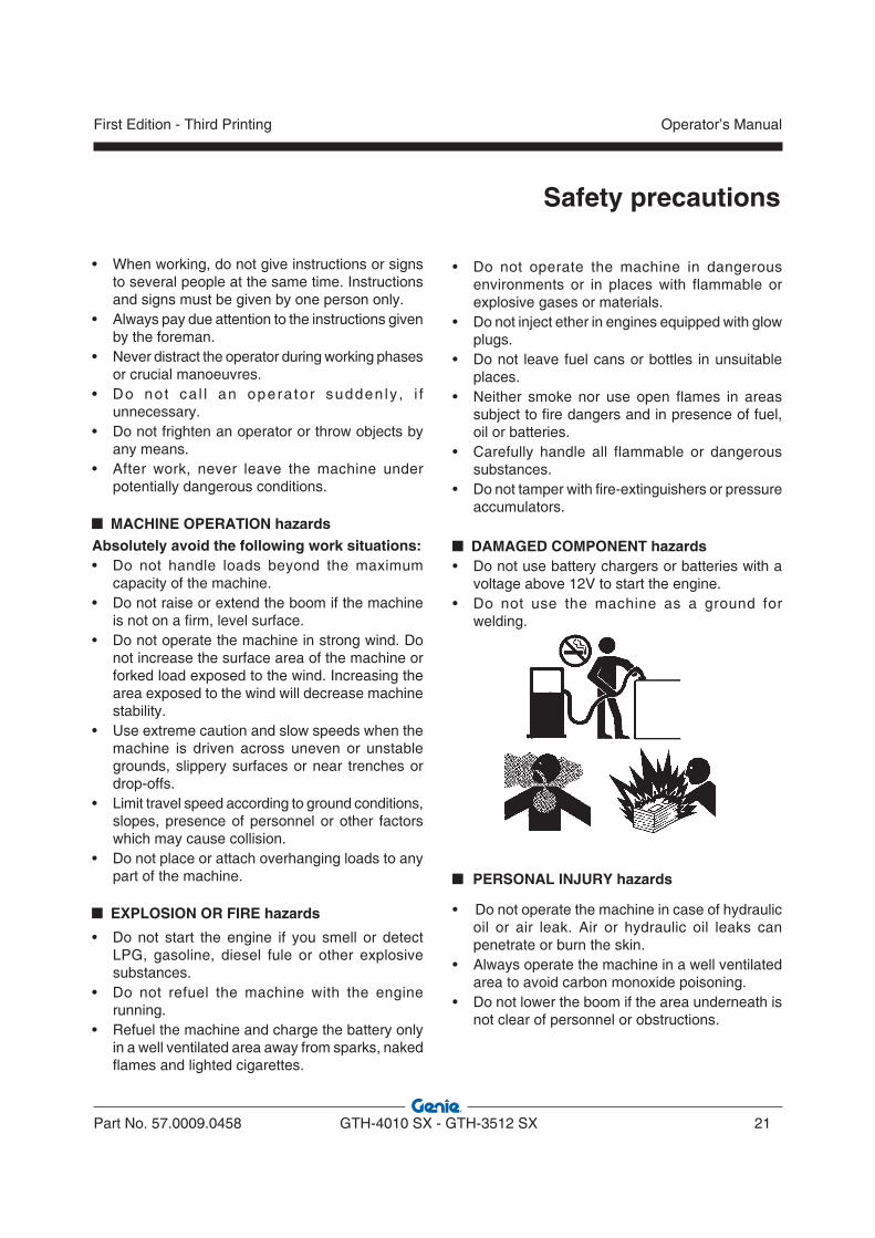
DAMAGED COMPONENT hazards• Do not use battery chargers or batteries with a
voltage above 12V to start the engine.• Do not use the machine as a ground for
welding.
PERSONAL INJURY hazards
• Do not operate the machine in case of hydraulic oil or air leak. Air or hydraulic oil leaks can penetrate or burn the skin.
• Always operate the machine in a well ventilated area to avoid carbon monoxide poisoning.
• Do not lower the boom if the area underneath is not clear of personnel or obstructions.
• When working, do not give instructions or signs to several people at the same time. Instructions and signs must be given by one person only.
• Always pay due attention to the instructions given by the foreman.
• Never distract the operator during working phases or crucial manoeuvres.
• Do no t ca l l an opera tor sudden ly , i f unnecessary.
• Do not frighten an operator or throw objects by any means.
• After work, never leave the machine under potentially dangerous conditions.
MACHINE OPERATION hazardsAbsolutely avoid the following work situations:• Do not handle loads beyond the maximum
capacity of the machine.• Do not raise or extend the boom if the machine
is not on a firm, level surface.• Do not operate the machine in strong wind. Do
not increase the surface area of the machine or forked load exposed to the wind. Increasing the area exposed to the wind will decrease machine stability.
• Use extreme caution and slow speeds when the machine is driven across uneven or unstable grounds, slippery surfaces or near trenches or drop-offs.
• Limit travel speed according to ground conditions, slopes, presence of personnel or other factors which may cause collision.
• Do not place or attach overhanging loads to any part of the machine.
EXPLOSION OR FIRE hazards
• Do not start the engine if you smell or detect LPG, gasoline, diesel fule or other explosive substances.
• Do not refuel the machine with the engine running.
• Refuel the machine and charge the battery only in a well ventilated area away from sparks, naked flames and lighted cigarettes.
Safety precautions

Intentionally blank page
Operator’s Manual
22 GTH-4010 SX - GTH-3512 SX Part No. 57.0009.0458
First Edition - Third Printing
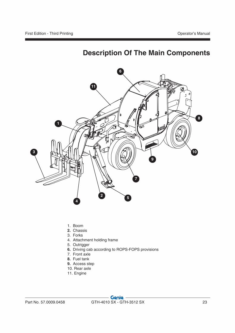
1. Boom 2. Chassis3. Forks4. Attachment holding frame5. Outrigger6. Driving cab according to ROPS-FOPS provisions7. Front axle8. Fuel tank9. Access step10. Rear axle11. Engine
1
2
3
45
6
7
8
9
10
11
Description Of The Main Components
Part No. 57.0009.0458 GTH-4010 SX - GTH-3512 SX 23
Operator’s ManualFirst Edition - Third Printing

Intentionally blank page
Operator’s Manual
24 GTH-4010 SX - GTH-3512 SX Part No. 57.0009.0458
First Edition - Third Printing
P
K
K
K
K
K
K
K
K
K
K
K
K
K
K
K
K
K
K
K
K
F22
F23
F24
F25
F26
F27
F16
F17
F18
F19
F20
F21
F13
F14
F15
F7
F8
F9
F10
F11
F12
F1
F2
F3
F4
F5
F6
INT
INT
KK23
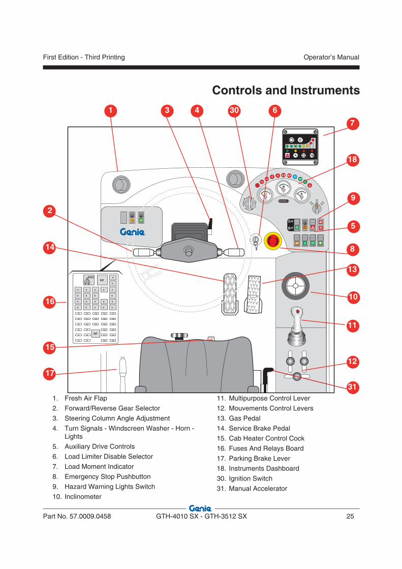
Controls and Instruments
1. Fresh Air Flap
2. Forward/Reverse Gear Selector
3. Steering Column Angle Adjustment
4. Turn Signals - Windscreen Washer - Horn - Lights
5. Auxiliary Drive Controls
6. Load Limiter Disable Selector
7. Load Moment Indicator
8. Emergency Stop Pushbutton
9. Hazard Warning Lights Switch 10. Inclinometer
11. Multipurpose Control Lever
12. Mouvements Control Levers
13. Gas Pedal
14. Service Brake Pedal
15. Cab Heater Control Cock
16. Fuses And Relays Board
17. Parking Brake Lever
18. Instruments Dashboard
30. Ignition Switch
31. Manual Accelerator
13
17
1
11
15
10
12
3
14
2
16
6
5
4
7
8
18
9
30
31
Part No. 57.0009.0458 GTH-4010 SX - GTH-3512 SX 25
Operator’s ManualFirst Edition - Third Printing
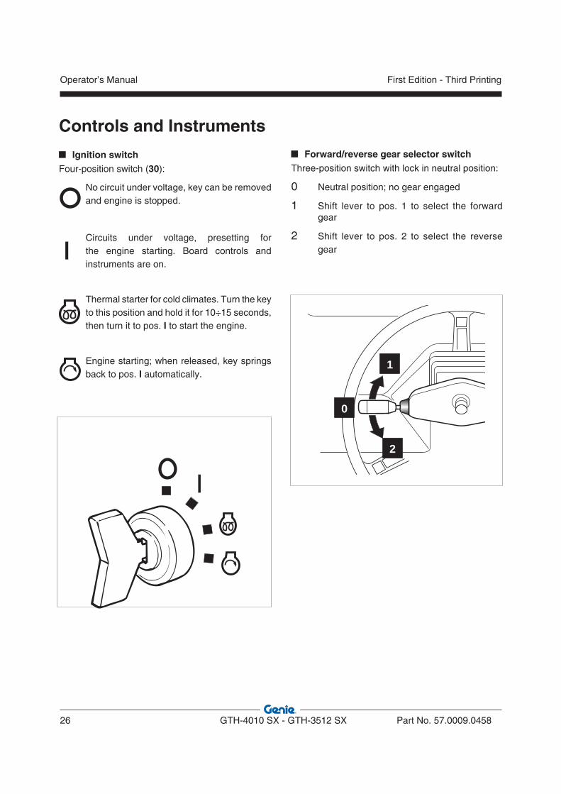
Ignition switchFour-position switch (30):
No circuit under voltage, key can be removed and engine is stopped.
Circuits under voltage, presetting for the engine starting. Board controls and instruments are on.
Thermal starter for cold climates. Turn the key to this position and hold it for 10÷15 seconds, then turn it to pos. I to start the engine.
Engine starting; when released, key springs back to pos. I automatically.
Forward/reverse gear selector switchThree-position switch with lock in neutral position:
0 Neutral position; no gear engaged
1 Shift lever to pos. 1 to select the forward gear
2 Shift lever to pos. 2 to select the reverse gear
1
2
0
Controls and Instruments
Operator’s Manual
26 GTH-4010 SX - GTH-3512 SX Part No. 57.0009.0458
First Edition - Third Printing

Lights function: To switch the handler lights, lever can be set to three different positions along its horizontal axis:
0 low beam ON, stable condition
1 high beam ON, stable condition
2 high beam used for intermittent signalling; when released, the lever springs back to position 0.
Turn signals function: Set lever to pos. 1 to indicate a turn leftwards or to pos. 2 to indicate a turn rightwards.
Turn signals - Windscreen wiper - Horn - Lights
Horn function: When sliding the lever along its axis, horn switches on, independently from other pre-set functions.
Windscreen washer function: Push the second stage of the lever along its axis to direct a jet of water onto the cab windscreen.
Windscreen wiper function: To operate the windscreen wiper, rotate the lever tip to one of the four positions:
I Intermittence (not activated)
0 Wiper OFF
J Low speed
I I High speed
ΙΙ
IΙ
ΙI
ΙΙ
I
ΙΙ
I
ΙΙ
I
�
�
� ��
ΙΙ
I
Controls and Instruments
Part No. 57.0009.0458 GTH-4010 SX - GTH-3512 SX 27
Operator’s ManualFirst Edition - Third Printing
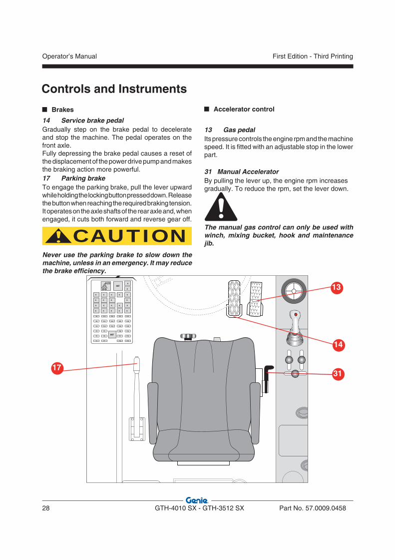
Brakes
14 Service brake pedalGradually step on the brake pedal to decelerate and stop the machine. The pedal operates on the front axle.Fully depressing the brake pedal causes a reset of the displacement of the power drive pump and makes the braking action more powerful.17 Parking brakeTo engage the parking brake, pull the lever upward while holding the locking button pressed down. Release the button when reaching the required braking tension. It operates on the axle shafts of the rear axle and, when engaged, it cuts both forward and reverse gear off.
CAUTIONNever use the parking brake to slow down the machine, unless in an emergency. It may reduce the brake efficiency.
Accelerator control
13 Gas pedalIts pressure controls the engine rpm and the machine speed. It is fitted with an adjustable stop in the lower part.
31 Manual AcceleratorBy pulling the lever up, the engine rpm increasesgradually. To reduce the rpm, set the lever down.
The manual gas control can only be used with winch, mixing bucket, hook and maintenance jib.
K
K
K
K
K
K
K
K
K
K
K
K
K
K
K
K
K
K
K
K
F22
F23
F24
F25
F26
F27
F16
F17
F18
F19
F20
F21
F13
F14
F15
F7
F8
F9
F10
F11
F12
F1
F2
F3
F4
F5
F6
INT
INT
KK23
Controls and Instruments
13
14
1731
Operator’s Manual
28 GTH-4010 SX - GTH-3512 SX Part No. 57.0009.0458
First Edition - Third Printing
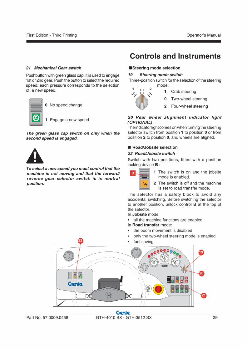
Steering mode selection
19 Steering mode switch Three-position switch for the selection of the steering
mode:
1 Crab steering
0 Two-wheel steering
2 Four-wheel steering
20 Rear wheel alignment indicator light (OPTIONAL) The indicator light comes on when turning the steering selector switch from position 1 to position 0 or from position 2 to position 0, and wheels are aligned.
Road/Jobsite selection22 Road/Jobsite switchSwitch with two positions, fitted with a position locking device B :
1 The switch is on and the jobsite mode is enabled.
2 The switch is off and the machine is set to road transfer mode.
The selector has a safety block to avoid any accidental switching. Before switching the selector to another position, unlock control B at the top of the selector.In Jobsite mode:• all the machine functions are enabledIn Road transfer mode:• the boom movement is disabled• only the two-wheel steering mode is enabled• fuel saving
21 Mechanical Gear switch
Pushbutton with green glass cap, it is used to engage 1st or 2nd gear. Push the button to select the required speed: each pressure corresponds to the selection of a new speed.
0 No speed change
1 Engage a new speed
The green glass cap switch on only when the second speed is engaged.
To select a new speed you must control that the machine is not moving and that the forward/reverse gear selector switch is in neutral position.
1 2
Controls and Instruments
P
19
22
21
20
B
Part No. 57.0009.0458 GTH-4010 SX - GTH-3512 SX 29
Operator’s ManualFirst Edition - Third Printing

6 Load Limiter Disable Selector
The load limiter can be deactivated operating the key-selector placed under the protection cover.
DANGERWORKING WITH THE LOAD LIMITING SYSTEM CUT OUT CAN RESULT IN A MACHINE OVERTURNING AND IN SERIOUS INJURY.
Safety and emergency devices
9 Hazard Warning Lights Switch
Fitted with on-off position, it switches on the turn signals simultaneously. When the hazard warning light is lit, the relevant switch and the turn signals light start flashing.
8 Emergency Stop Pushbutton
By pressing this button, the engine of the machine is shut down.Before restarting the machine, it is necessary to reset the pushbutton by rotating it clockwise.
Controls and Instruments
P
9
6
8
Operator’s Manual
30 GTH-4010 SX - GTH-3512 SX Part No. 57.0009.0458
First Edition - Third Printing
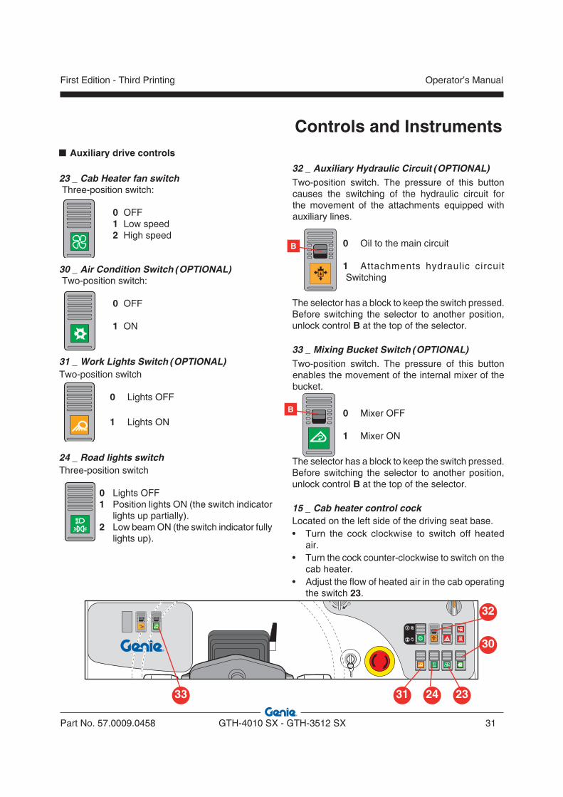
Auxiliary drive controls
23 _ Cab Heater fan switch Three-position switch:
0 OFF 1 Low speed 2 High speed
30 _ Air Condition Switch (OPTIONAL) Two-position switch:
0 OFF 1 ON
31 _ Work Lights Switch (OPTIONAL)Two-position switch
0 Lights OFF
1 Lights ON
24 _ Road lights switchThree-position switch
0 Lights OFF 1 Position lights ON (the switch indicator
lights up partially). 2 Low beam ON (the switch indicator fully
lights up).
32 _ Auxiliary Hydraulic Circuit (OPTIONAL)Two-position switch. The pressure of this button causes the switching of the hydraulic circuit for the movement of the attachments equipped with auxiliary lines.
0 Oil to the main circuit
1 Attachments hydraulic circuit Switching
The selector has a block to keep the switch pressed. Before switching the selector to another position, unlock control B at the top of the selector.
33 _ Mixing Bucket Switch (OPTIONAL)Two-position switch. The pressure of this button enables the movement of the internal mixer of the bucket.
0 Mixer OFF
1 Mixer ON
The selector has a block to keep the switch pressed. Before switching the selector to another position, unlock control B at the top of the selector.
15 _ Cab heater control cockLocated on the left side of the driving seat base.• Turn the cock clockwise to switch off heated
air.• Turn the cock counter-clockwise to switch on the
cab heater. • Adjust the flow of heated air in the cab operating
the switch 23.
Controls and Instruments
B
33
32
30
31 2324
B
Part No. 57.0009.0458 GTH-4010 SX - GTH-3512 SX 31
Operator’s ManualFirst Edition - Third Printing
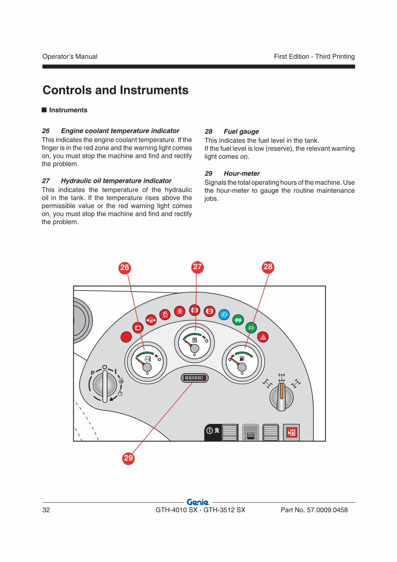
Instruments
26 Engine coolant temperature indicatorThis indicates the engine coolant temperature. If the finger is in the red zone and the warning light comes on, you must stop the machine and find and rectify the problem.
27 Hydraulic oil temperature indicatorThis indicates the temperature of the hydraulic oil in the tank. If the temperature rises above the permissible value or the red warning light comes on, you must stop the machine and find and rectify the problem.
28 Fuel gaugeThis indicates the fuel level in the tank.If the fuel level is low (reserve), the relevant warning light comes on.
29 Hour-meterSignals the total operating hours of the machine. Use the hour-meter to gauge the routine maintenance jobs.
P
Controls and Instruments
29
26 27 28
Operator’s Manual
32 GTH-4010 SX - GTH-3512 SX Part No. 57.0009.0458
First Edition - Third Printing

Warning lights (ref. 18 and 5)
18.1 Warning light - low battery chargeSignals a low charge by the alternator.18.2 Warning light - low engine oil pressureIt lights when the engine oil pressure is too low.18.3 Warning light - air filter restrictedWhen this lamp come on, proceed with cleaning or changing the air filter cartridge.18.4 Warning light - mechanical gearThis red light comes on to warn of a problem of the mechanical gear. Contact the TEREXLIFT Service Centre.18.5 Warning light - parking brake engagedWhen ON, this light indicates that the parking brake is engaged.18.6 Warning light - low brake pressureIt lights when the pressure of the braking circuit is too low for a correct functioning.18.7 Warning light - high beamBlue warning light that signals when high beam is ON.
18.8 Warning light - turn signalsGreen indicator light that signals when turn signals are ON.18.9 Warning light - position lightsGreen warning light that signals when position lights are ON. 18.10 General alarm warning lightThis red light comes on to warn of a problem of the machine. Contact the TEREXLIFT Service Centre.18.11 Warning light - glow plugs preheatingThis orange light comes on during the pre-heating of the engine glow plugs. Before starting the engine wait for this light to go off.5.1 Warning light - hydraulic oil filter cloggedWhen this lamp sets to on, immediately change the oil filter on the return line to the tank.
5.2 Warning light - low hydraulic oil levelThis light comes on to alert to a low level of the hydraulic oil for a correct functioning. Replenish and eliminate the oil leak
Controls and Instruments
18.2 18.318.118.11 18.718.5 18.618.4 18.1018.8 18.9 5.25.1
Part No. 57.0009.0458 GTH-4010 SX - GTH-3512 SX 33
Operator’s ManualFirst Edition - Third Printing
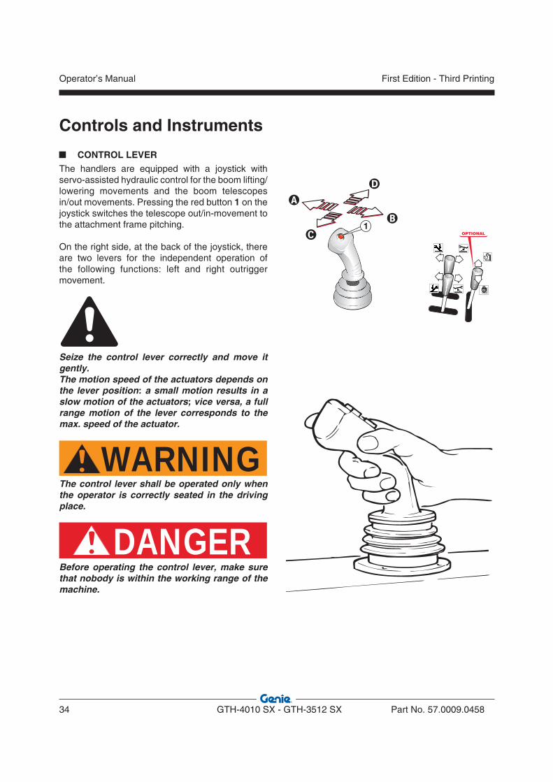
CONTROL LEVERThe handlers are equipped with a joystick with servo-assisted hydraulic control for the boom lifting/lowering movements and the boom telescopes in/out movements. Pressing the red button 1 on the joystick switches the telescope out/in-movement to the attachment frame pitching.
On the right side, at the back of the joystick, there are two levers for the independent operation of the following functions: left and right outrigger movement.
Seize the control lever correctly and move it gently.The motion speed of the actuators depends on the lever position: a small motion results in a slow motion of the actuators; vice versa, a full range motion of the lever corresponds to the max. speed of the actuator.
WARNINGThe control lever shall be operated only when the operator is correctly seated in the driving place.
DANGERBefore operating the control lever, make sure that nobody is within the working range of the machine.
1OPTIONAL
Controls and Instruments
Operator’s Manual
34 GTH-4010 SX - GTH-3512 SX Part No. 57.0009.0458
First Edition - Third Printing
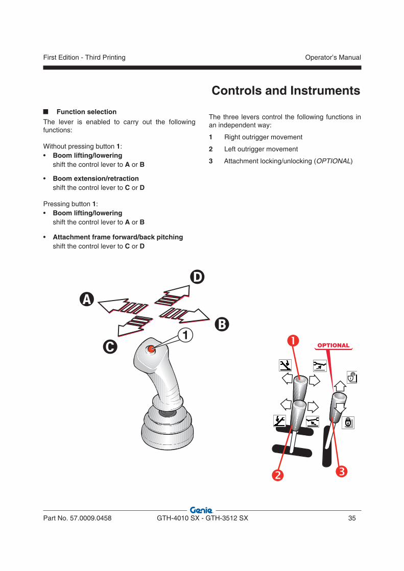
Function selectionThe lever is enabled to carry out the following functions:
Without pressing button 1:• Boom lifting/lowering shift the control lever to A or B
• Boom extension/retraction shift the control lever to C or D
Pressing button 1:• Boom lifting/lowering shift the control lever to A or B
• Attachment frame forward/back pitching shift the control lever to C or D
The three levers control the following functions in an independent way:
1 Right outrigger movement
2 Left outrigger movement
3 Attachment locking/unlocking (OPTIONAL)
1OPTIONAL
Controls and Instruments
Part No. 57.0009.0458 GTH-4010 SX - GTH-3512 SX 35
Operator’s ManualFirst Edition - Third Printing
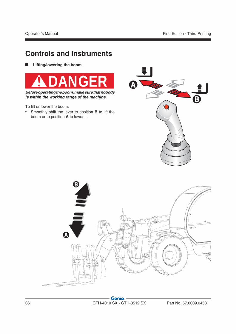
Lifting/lowering the boom
DANGERBefore operating the boom, make sure that nobody is within the working range of the machine.
To lift or lower the boom:• Smoothly shift the lever to position B to lift the
boom or to position A to lower it.
�
�
Controls and Instruments
Operator’s Manual
36 GTH-4010 SX - GTH-3512 SX Part No. 57.0009.0458
First Edition - Third Printing
�
�
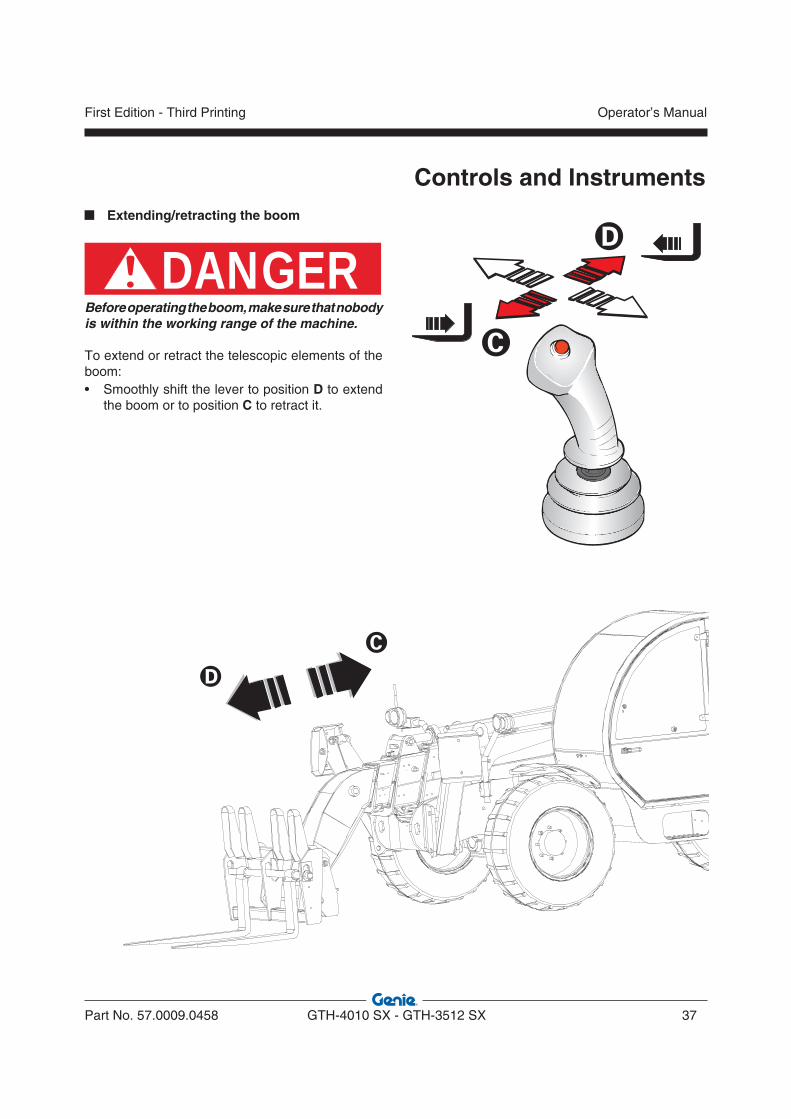
Extending/retracting the boom
DANGERBefore operating the boom, make sure that nobody is within the working range of the machine.
To extend or retract the telescopic elements of the boom:• Smoothly shift the lever to position D to extend
the boom or to position C to retract it.
Controls and Instruments
Part No. 57.0009.0458 GTH-4010 SX - GTH-3512 SX 37
Operator’s ManualFirst Edition - Third Printing

Pitching the attachment holding frame forward/back
DANGERBefore operating the boom, make sure that nobody is within the working range of the machine.
To tilt forward/back the attachment holding frame:• Press the button 1 on the joystick• Smoothly shift the lever to position D to pitch the
holding frame forward or to position C to pitch the holding frame back.
�
1
�
Controls and Instruments
Operator’s Manual
38 GTH-4010 SX - GTH-3512 SX Part No. 57.0009.0458
First Edition - Third Printing

Controls and Instruments
Quick-coupling the attachments (OPTIONAL)
DANGERBefore operating the boom, make sure that nobody is within the working range of the machine.
To lock/unlock the attachments:• Shift the lever 3 toward the cab windscreen D to
release the attachment • Shift the lever toward the operator’s seat C to lock
the attachment.
WARNINGBefore using the machine, visually check the attachment is correctly coupled.
OPTIONAL
�
�
�
�
Part No. 57.0009.0458 GTH-4010 SX - GTH-3512 SX 39
Operator’s ManualFirst Edition - Third Printing
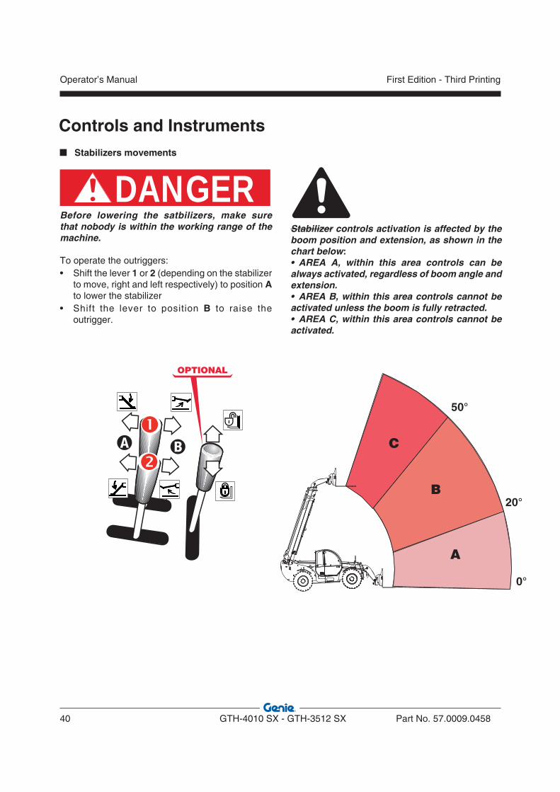
Stabilizers movements
DANGERBefore lowering the satbilizers, make sure that nobody is within the working range of the machine.
To operate the outriggers:• Shift the lever 1 or 2 (depending on the stabilizer
to move, right and left respectively) to position A to lower the stabilizer
• Shift the lever to position B to raise the outrigger.
OPTIONAL
Controls and Instruments
Stabilizer controls activation is affected by the boom position and extension, as shown in the chart below:• AREA A, within this area controls can be always activated, regardless of boom angle and extension.• AREA B, within this area controls cannot be activated unless the boom is fully retracted.• AREA C, within this area controls cannot be activated.
A
B
C
50°
20°
0°
��
Operator’s Manual
40 GTH-4010 SX - GTH-3512 SX Part No. 57.0009.0458
First Edition - Third Printing
Inspections
Make sure:
You learn and practice the principles of safe machine operation contained in this operator's manual.
1 Avoid hazardous situations.
2 Always perform a pre-operation inspection.
Know and understand the pre-operation inspection before going on to the next section.
3 Always perform function tests prior to use.
4 Inspect the workplace.
5 Only use the machine as it was intended.
Pre-operation Inspection FundamentalsIt is the responsibility of the operator to perform a pre-operation inspection and routine maintenance.
The pre-operation inspection is a visual inspection performed by the operator prior to each work shift. The inspection is designed to discover if anything is apparently wrong with a machine before the operator performs the function tests.
The pre-operation inspection also serves to determine if routine maintenance procedures are required. Only routine maintenance items specified in this manual may be performed by the operator.
Refer to the list on the next page and check each of the items.
If damage or any unauthorized variation from factory delivered condition is discovered, the machine must be tagged and removed from service.
Repairs to the machine may only be made by a qualified service technician, according to the manufacturer's specifications. After repairs are completed, the operator must perform a pre-operation inspection again before going on to the function tests.
Scheduled maintenance inspections shall be performed by qualified service technicians, according to the manufacturer's specifications.
Part No. 57.0009.0458 GTH-4010 SX - GTH-3512 SX 41
Operator’s ManualFirst Edition - Third Printing
Inspections PRE-OPERATION INSPECTION
• Make sure the operator’s manual is intact, legible and placed inside the machine.
• Make sure all decals are present and legible. See “Labels and plates applied on the machine” chapter.
• Check for engine oil leaks and proper oil level. Top up if necessary. See “Maintenance” chapter.
• Check for axle oil leaks and proper oil level. Top up if necessary. See “Maintenance” chapter.
• Check for hydraulic oil leaks and proper oil level. Top up if necessary. See “Maintenance” chapter.
• Check for engine coolant leaks and proper coolant level. Add coolant if necessary. See “Maintenance” chapter.
• Check for battery fluid leaks and proper fluid level. Add distilled water if necessary. See “Maintenance” chapter.
Check the following components or zones for damage, missing or wrongly fitted parts or non-authorised modifications: • electrical components, wiring and electrical
cables • hydraulic hoses, fittings, cylinders and main
valves • fuel and hydraulic oil tanks • drive pump and motor and transmission
axles • steering system • braking system • boom telescopes sliding pads • clean glasses, lights and rear view mirrors • engine and relevant components • horn • lights • machine ignition control • nuts, bolts and other fastenersCheck the entire machine for: • cracks on welds or structural components • dents or damage to the machine
* Make sure that all structural and other critical components are present and the relevant fasteners and pins are fitted and properly tightened.
* After inspection, check that all the compartment covers are in place and latched.
WARNINGIf even one single item is damaged or defective, do not start work. Stop the machine and repair the fault.
Checking the tyres* Check the correct inflation of the tyres; see
par. “Tyres and Wheels” in the Maintenance section.
* Make sure that the tyre plies are not cut or worn.
WARNINGA tyre burst may result in serious injury; never use the machine if tyres are worn, wrongly inflated or damaged.
NOTICE If the machine shall be used in a marine or equivalent environment, protect it against salt deposits with an adequate treatment against saltiness to prevent rust formation.
Operator’s Manual
42 GTH-4010 SX - GTH-3512 SX Part No. 57.0009.0458
First Edition - Third Printing
Inspections
Test the Control Lever
7 Using the control lever, momentarily raise and lower the boom, extend and retract the boom.
Result: All functions should operate smoothly.
8 Using the control lever and the red button, momentarily tilt the forks up and tilt the forks down.
Result: The function should operate smoothly.
9 Using the control lever 3, momentarily lock and unlock the attachment (OPTIONAL).
Result: The function should operate smoothly.
Test the Steering
10 Push the right side of the steer selector switch to select four-wheel steer.
11 Check the steering operation by turning the steering wheel approximately ¼ turn in each direction.
Result: The front wheels should turn in the same direction as the steering wheel. The rear wheels should turn in the opposite direction.
12 Straighten the wheels.
13 Push the steer selector switch to the middle position to select two-wheel steer.
14 Check the steering operation by turning the steering wheel approximately ¼ turn in each direction.
Result: The front wheels should turn in the same direction as the steering wheel. The rear wheels should not turn.
15 Straighten the wheels.
16 Push the left side of the steer selector switch to select crab steer.
17 Check the steering operation by turning the steering wheel approximately ¼ turn in each direction.
Result: The front wheels and rear wheels should turn in the same direction as the steering wheel.
TESTS1 Select a test area that is firm, level and free
of obstruction. Be sure there is no load on the forks or attachment.
2 Enter the operator's compartment and sit on the seat.
3 Fasten the seat belt.
4 Adjust the interior rear view mirror and the exterior right hand mirror, if required.
5 Be sure the parking brake is on and the transmission control is in neutral.
6 Start the engine. See par. “Starting the Engine” in the Operating Instructions section.
FUNCTION TESTS FUNDAMENTALS
The function tests are designed to discover any malfunctions before the machine is put into service. The operator must follow the step-by-step instructions to test all machine functions. A malfunctioning machine must never be used. If malfunctions are discovered, the machine must be tagged and removed from service. Repairs to the machine may only be made by a qualified service technician, according to the manufacturer's specifications. After repairs are completed, the operator must perform a pre-operation inspection and function tests again before putting the machine into service.
Make sure: You learn and practice the principles of safe machine operation contained in this operator’s manual.
1 Avoid hazardous situations.
2 Always perform a pre-operation inspection.
Know and understand the pre-operation inspection before going on to the next section.
3 Always perform function tests prior to use.
4 Inspect the workplace.
5 Only use the machine as it was intended.
Part No. 57.0009.0458 GTH-4010 SX - GTH-3512 SX 43
Operator’s ManualFirst Edition - Third Printing
WORKPLACE INSPECTION
The workplace inspection helps the operator determine if the workplace is suitable for safe machine operation. It should be performed by the operator prior to moving the machine to the workplace.
It is the operator's responsibility to read and remember the workplace hazards, then watch for and avoid them while moving, setting up and operating the machine
Be aware of and avoid the following hazardous situations:
• drop-offs or holes
• bumps, floor obstructions or debris
• sloped surfaces
• unstable or slippery surfaces
• overhead obstructions and high voltage conductors
• hazardous locations
• inadequate surface support to withstand all load forces imposed by the machine
• wind and weather conditions
• the presence of unauthorized personnel
• other possible unsafe conditions
Inspections
Test the Transmission and Brakes
18 Be sure the boom is fully lowered and retracted.
19 Step on the service brake pedal.
20 Move the transmission control lever to forward. Slowly let up on the service brake pedal. As soon as the machine starts to move, push the service brake pedal.
Result: The machine should move forward, then come to an abrupt stop.
21 Move the transmission control lever to reverse. Slowly let up on the service brake pedal. As soon as the machine starts to move, push the service brake pedal.
Result: The machine should move in reverse, then come to an abrupt stop. The back-up alarm should sound when the transmission control lever is in reverse.
22 Move the transmission control lever to neutral.
23 Pull the parking brake lever upward.
Result: The red parking brake indicator light should come on, indicating the parking brake is on.
24 Move the transmission control lever forward, then in reverse.
Result: The machine should not move.
25 Push the parking brake lever downward. The parking brake is off when the indicator light is off.
Test the Stabilizers
26 Using the control lever 1 and 2, fully lower and raise the stabilizers.
Result: The stabilizers should operate moothly.
27 Raise the boom over 20° and extend it.
Result: The stabilizers should not work.
Test the Road Lights
29 Verify that all lights are functional.
Operator’s Manual
44 GTH-4010 SX - GTH-3512 SX Part No. 57.0009.0458
First Edition - Third Printing

Operating Instructions
This chapter describes some techniques and provides instructions for a safe use of the machine fitted with standard forks. Before using different attachments, thoroughly read the chapter “Optional attachments”.
WARNINGBefore using the machine, inspect the job site and check for possible hazardous conditions. Make sure that there are no holes, moving banks or debris that may cause you to lose the control of the machine.
DANGERPay the greatest attention when working close to electric lines. Check their position and ensure that no part of the machine operates at less than 6 meters from the power lines.
WARNINGFor a safe use of the machine, always check the weight of the loads going to be handled.
Part No. 57.0009.0458 GTH-4010 SX - GTH-3512 SX 45
Operator’s ManualFirst Edition - Third Printing

ENTERING THE MACHINE
ENTERING THE CAB
CAUTIONAlways make sure that your hands and shoe soles are clean and dry before getting into the driving cab. Always face the machine when entering and leaving it and hold to the suitable handles.
The handler cab is equipped with an access door on the left-hand side.
Door opening from outside: • Insert the key and release
lock 1.• Press the pushbutton 1
and open the door.
Door closing from inside: Pull the door with force: it locks automatically.
Door opening from inside:• Lower lever 2 and release
the lock to open the door completely.
• Rotate handle 3 to open the upper section of the door and lock it against the special catch.
CAUTIONThe upper section of the door must be secured to the rear part of the driving cab or latched to the lower section of the same door.
To unlock the door latched in open position:
• Press button 4to unlock the door from the catch
• Once released, re-close the upper section of the door by means of handle 3.
Leaving the cab in an emergency In an emergency, use the rear window of the cab as safety exit-way.This window has special locking handles with plastic pins 5 easy to pull out when you need to fully open the glass.
Operating Instructions
Operator’s Manual
46 GTH-4010 SX - GTH-3512 SX Part No. 57.0009.0458
First Edition - Third Printing
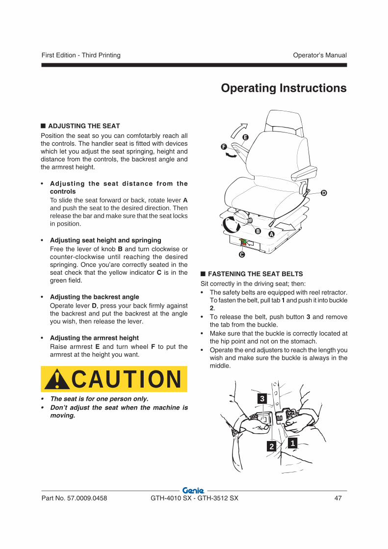
ADJUSTING THE SEAT Position the seat so you can comfotarbly reach all the controls. The handler seat is fitted with devices which let you adjust the seat springing, height and distance from the controls, the backrest angle and the armrest height.
• Adjusting the seat distance from the controls
To slide the seat forward or back, rotate lever A and push the seat to the desired direction. Then release the bar and make sure that the seat locks in position.
• Adjusting seat height and springing Free the lever of knob B and turn clockwise or
counter-clockwise until reaching the desired springing. Once you’are correctly seated in the seat check that the yellow indicator C is in the green field.
• Adjusting the backrest angle Operate lever D, press your back firmly against
the backrest and put the backrest at the angle you wish, then release the lever.
• Adjusting the armrest height Raise armrest E and turn wheel F to put the
armrest at the height you want.
CAUTION• The seat is for one person only.• Don’t adjust the seat when the machine is
moving.
FASTENING THE SEAT BELTSSit correctly in the driving seat; then:• The safety belts are equipped with reel retractor.
To fasten the belt, pull tab 1 and push it into buckle 2.
• To release the belt, push button 3 and remove the tab from the buckle.
• Make sure that the buckle is correctly located at the hip point and not on the stomach.
• Operate the end adjusters to reach the length you wish and make sure the buckle is always in the middle.
3
2 1
Operating Instructions
Part No. 57.0009.0458 GTH-4010 SX - GTH-3512 SX 47
Operator’s ManualFirst Edition - Third Printing
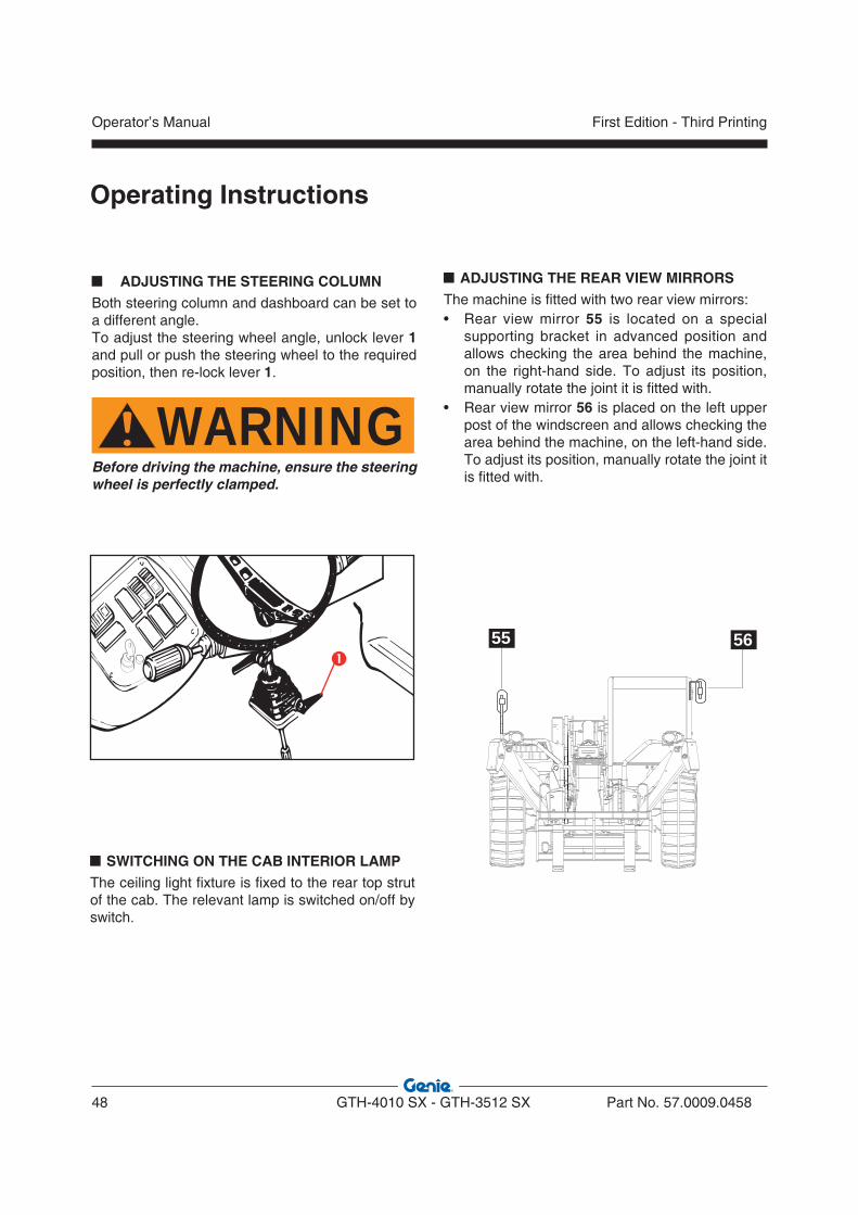
ADJUSTING THE REAR VIEW MIRRORSThe machine is fitted with two rear view mirrors:• Rear view mirror 55 is located on a special
supporting bracket in advanced position and allows checking the area behind the machine, on the right-hand side. To adjust its position, manually rotate the joint it is fitted with.
• Rear view mirror 56 is placed on the left upper post of the windscreen and allows checking the area behind the machine, on the left-hand side. To adjust its position, manually rotate the joint it is fitted with.
5655
SWITCHING ON THE CAB INTERIOR LAMPThe ceiling light fixture is fixed to the rear top strut of the cab. The relevant lamp is switched on/off by switch.
ADJUSTING THE STEERING COLUMNBoth steering column and dashboard can be set to a different angle.To adjust the steering wheel angle, unlock lever 1 and pull or push the steering wheel to the required position, then re-lock lever 1.
WARNINGBefore driving the machine, ensure the steering wheel is perfectly clamped.
Operating Instructions
Operator’s Manual
48 GTH-4010 SX - GTH-3512 SX Part No. 57.0009.0458
First Edition - Third Printing
STARTING THE ENGINE
• Set the forward/back speed lever to neutral position.
• To start the engine, rotate the ignition switch to position , and release when the engine starts. If the engine does not start within 20 seconds, release the key and wait at least 2 minutes before attempting again.
• After the engine starting, slow down the rpm and wait some seconds before engaging a gear; this allows for a gradual warm up of the engine oil and a better lubrication.
• In case of engine jump-starting, remove the connecting cables (see following chapter).
NOTICEIf the light indicators do not switch off/on when engine is running, immediately stop the machine and find and rectify the fault.
WARNINGOnce it has been started, the engine continues to run even if you leave the driving place. DO NOT LEAVE THE DRIVING PLACE BEFORE HAVING SHUT THE ENGINE DOWN, LOWERED THE BOOM TO THE GROUND, TURNED THE SPEED SWITCH TO THE NEUTRAL POSITION AND ENGAGED THE PARKING BRAKE.
Engine can not be started if the speed switch is not in the neutral position.
JUMP-STARTING THE ENGINE
NOTICEDo not start the engine using a quick charge booster to avoid any damage to the electronic boards.
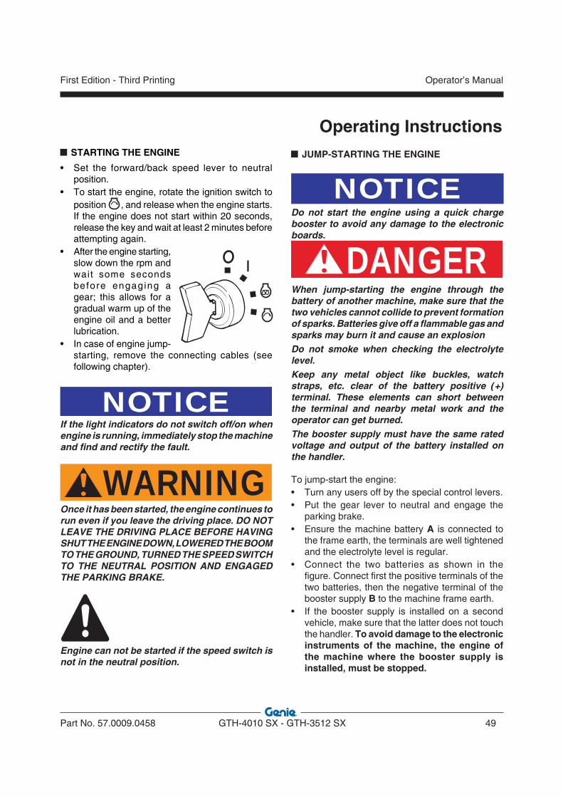
DANGERWhen jump-starting the engine through the battery of another machine, make sure that the two vehicles cannot collide to prevent formation of sparks. Batteries give off a flammable gas and sparks may burn it and cause an explosionDo not smoke when checking the electrolyte level.Keep any metal object like buckles, watch straps, etc. clear of the battery positive (+) terminal. These elements can short between the terminal and nearby metal work and the operator can get burned.The booster supply must have the same rated voltage and output of the battery installed on the handler.
To jump-start the engine:• Turn any users off by the special control levers.• Put the gear lever to neutral and engage the
parking brake.• Ensure the machine battery A is connected to
the frame earth, the terminals are well tightened and the electrolyte level is regular.
• Connect the two batteries as shown in the figure. Connect first the positive terminals of the two batteries, then the negative terminal of the booster supply B to the machine frame earth.
• If the booster supply is installed on a second vehicle, make sure that the latter does not touch the handler. To avoid damage to the electronic instruments of the machine, the engine of the machine where the booster supply is installed, must be stopped.
Operating Instructions
Part No. 57.0009.0458 GTH-4010 SX - GTH-3512 SX 49
Operator’s ManualFirst Edition - Third Printing

• Turn the ignition key and start the handler.• Disconnect the cables. Remove first the negative
terminal from the frame earth, then from the booster supply. Disconnect the positive terminal from the machine battery, then from the booster supply.
DANGERUse only a 12V battery; other devices like battery chargers, etc. may cause an explosion of the battery or result in damage to the electrical system.
�
�
LOW TEMPERATURE STARTINGIn case of cold starting, use an oil with a SAE viscosity adequate to the ambient temperature.Please refer to the engine use and maintenance manual.The machine is supplied with oil SAE 15W/40.
To start the engine from cold, proceed as follows:• Set the forward/back speed lever to neutral
position.• Turn the ignition switch to the glow plugs
preheating position and wait until the relevant warning light 18.11 goes off. Step down on the gas pedal and start the engine by turning the ignition switch. Release the switch as soon as the engine fires.
• Let the engine run at idle for a few seconds before putting a gear; this allows for a gradual warm up of the engine oil and a better lubrication.
Operating Instructions
Operator’s Manual
50 GTH-4010 SX - GTH-3512 SX Part No. 57.0009.0458
First Edition - Third Printing

STARTING THE MACHINEWhen the engine reaches the running temperature, ensure all parts are in transfer position and the gearbox lever is in neutral. Then, proceed as follows:• Select the required steering mode.• Select the required gear (forward or reverse).• Release the parking brake.• Slowly step on the gas pedal to start moving
off.
WARNINGDo not operate the forward/reverse gear lever when the machine is running. The machine would reverse the running direction abruptly and you could seriously be injured.
STOPPING AND PARKING THE MACHINEWhen possible, stop the machine on a dry, level and solid ground. Then:• Bring the machine to a smooth stop by easing up
the gas pedal and stepping down on the brake pedal.
• Set the forward/back speed lever to neutral position.
• Engage the parking brake and ensure its indicator light switches on.
• Release the service brake pedal.• Rest the attachment coupled to the boom flat on
the ground.• Rotate the ignition key to “0” and remove the
key.• Leave the driving cab and lock the cab door.
WARNINGAlways face the machine when getting off the driving cab; make sure that your hands and shoe soles are clean and dry, and hold to the handholds to prevent falls or slips.
WARNINGAlways engage the parking brake after stopping the machine to prevent possible accidental motions of the vehicle.
Operating Instructions
Part No. 57.0009.0458 GTH-4010 SX - GTH-3512 SX 51
Operator’s ManualFirst Edition - Third Printing

A B C D E
09.4618.1093
GTH-3512 SX
Operating Instructions
USING THE LOAD CHARTSThe load charts 1 indicates the maximum permissible load in relation to the boom extension and the type of attachment used. To operate under safe conditions, always refer to these charts. The extension level of the boom can be checked with the help of the letters (A, B, C, D, E) painted on the same boom (pos.3), while the actual degrees of inclination of the boom are shown by the angle indicator 2.All the load charts are placed into a dedicated holder installed in the right side of the cabin, on the top of the dashboard. The tag 4 located at the top of each load chart, indicates the type of attachment used.
The load charts illustrated in this manual are given only as a mere example. To define the payload limits, refer to the load charts applied within the cab of your machine.
WARNINGThe load charts applied on the cab refer to a stationary machine standing on a solid and level ground. Raise the load some centimetres and check its stability before raising it completely.
EXAMPLEEXAMPLE
Operator’s Manual
52 GTH-4010 SX - GTH-3512 SX Part No. 57.0009.0458
First Edition - Third Printing
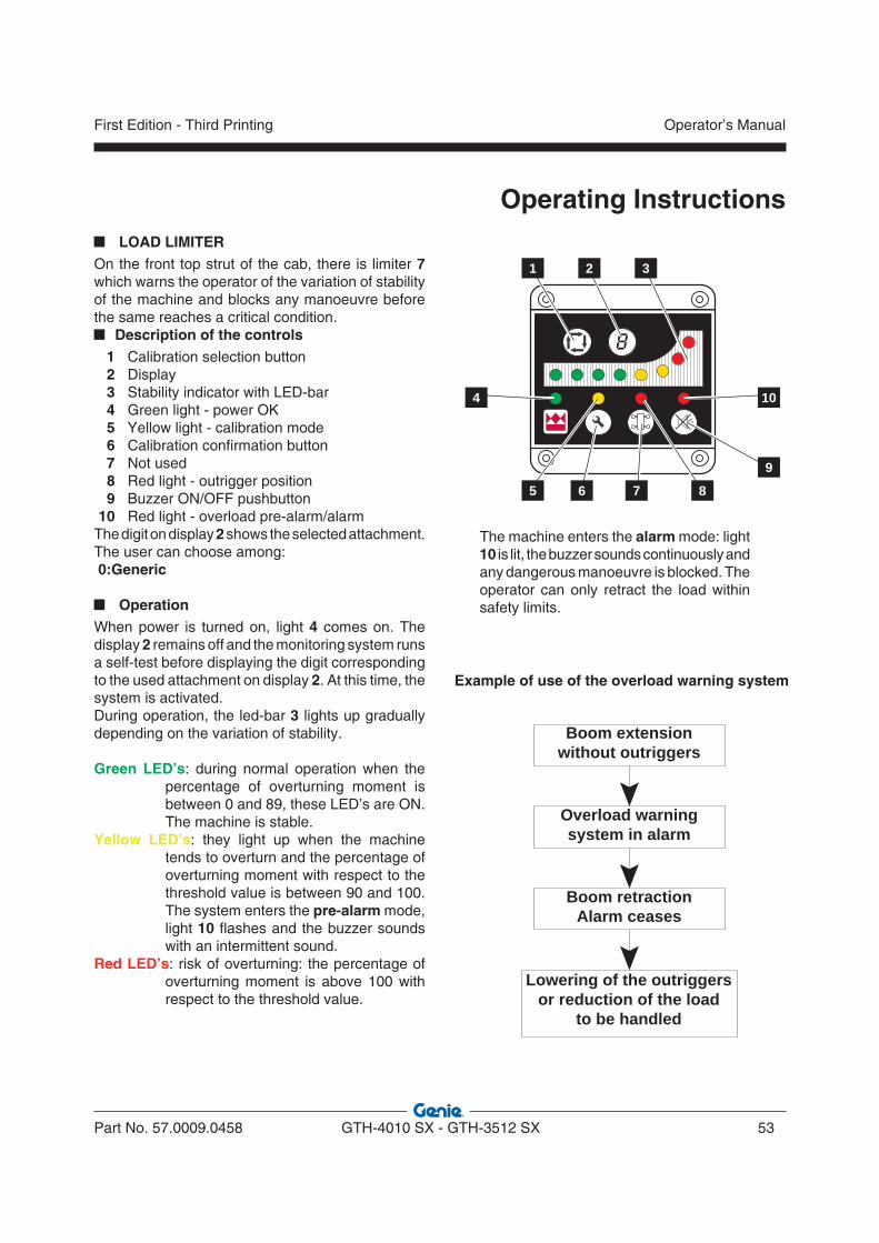
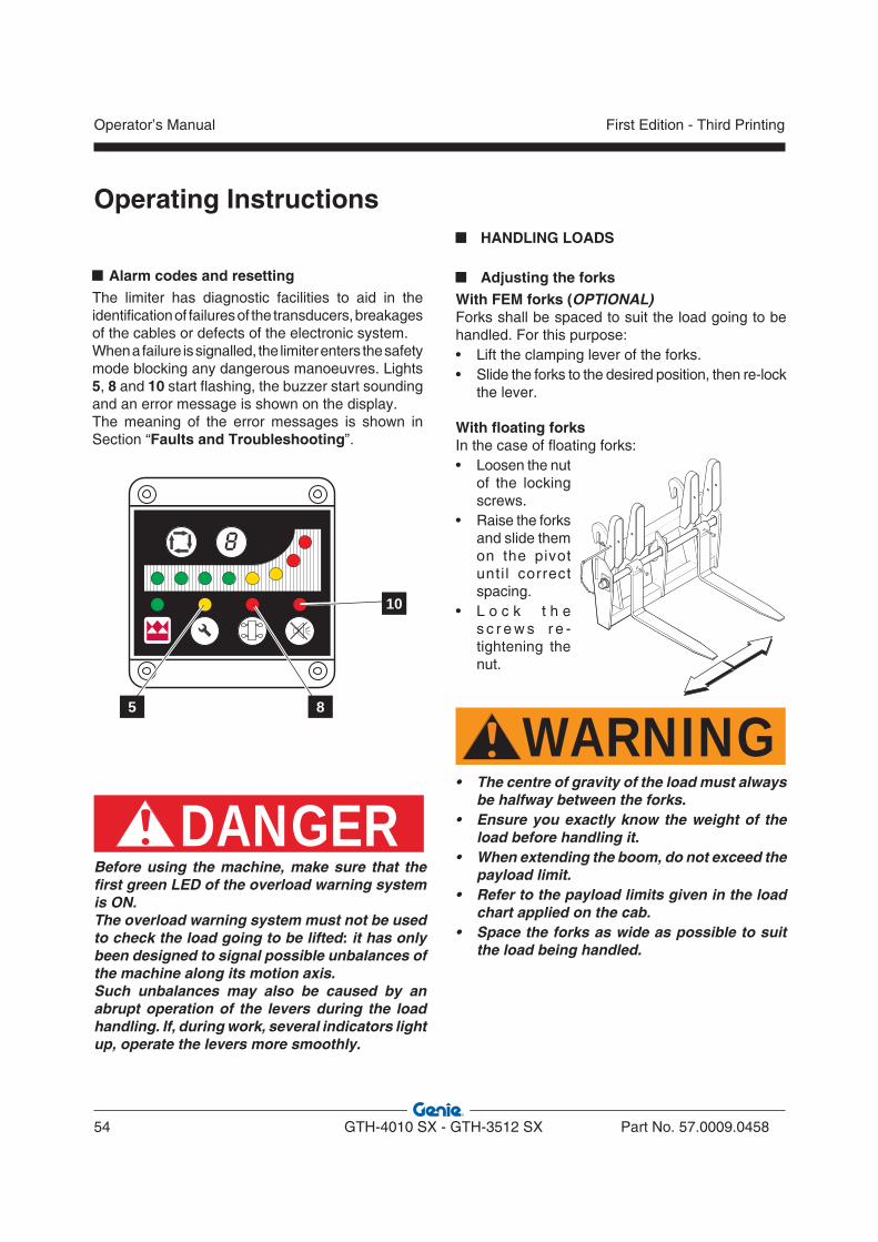
LOAD LIMITEROn the front top strut of the cab, there is limiter 7 which warns the operator of the variation of stability of the machine and blocks any manoeuvre before the same reaches a critical condition.
Description of the controls 1 Calibration selection button 2 Display 3 Stability indicator with LED-bar 4 Green light - power OK 5 Yellow light - calibration mode 6 Calibration confirmation button 7 Not used 8 Red light - outrigger position 9 Buzzer ON/OFF pushbutton 10 Red light - overload pre-alarm/alarmThe digit on display 2 shows the selected attachment. The user can choose among: 0:Generic
OperationWhen power is turned on, light 4 comes on. The display 2 remains off and the monitoring system runs a self-test before displaying the digit corresponding to the used attachment on display 2. At this time, the system is activated.During operation, the led-bar 3 lights up gradually depending on the variation of stability.
Green LED’s: during normal operation when the percentage of overturning moment is between 0 and 89, these LED’s are ON. The machine is stable.
Yellow LED’s: they light up when the machine tends to overturn and the percentage of overturning moment with respect to the threshold value is between 90 and 100. The system enters the pre-alarm mode, light 10 flashes and the buzzer sounds with an intermittent sound.
Red LED’s: risk of overturning: the percentage of overturning moment is above 100 with respect to the threshold value.
1 2 3
4
5 6 7 8
10
9
The machine enters the alarm mode: light 10 is lit, the buzzer sounds continuously and any dangerous manoeuvre is blocked. The operator can only retract the load within safety limits.
Example of use of the overload warning system
Boom retractionAlarm ceases
Lowering of the outriggers or reduction of the load
to be handled
Overload warningsystem in alarm
Boom extension without outriggers
Operating Instructions
Part No. 57.0009.0458 GTH-4010 SX - GTH-3512 SX 53
Operator’s ManualFirst Edition - Third Printing
DANGERBefore using the machine, make sure that the first green LED of the overload warning system is ON.The overload warning system must not be used to check the load going to be lifted: it has only been designed to signal possible unbalances of the machine along its motion axis.Such unbalances may also be caused by an abrupt operation of the levers during the load handling. If, during work, several indicators light up, operate the levers more smoothly.
Alarm codes and resettingThe limiter has diagnostic facilities to aid in the identification of failures of the transducers, breakages of the cables or defects of the electronic system.When a failure is signalled, the limiter enters the safety mode blocking any dangerous manoeuvres. Lights 5, 8 and 10 start flashing, the buzzer start sounding and an error message is shown on the display.The meaning of the error messages is shown in Section “Faults and Troubleshooting”.
5 8
10
HANDLING LOADS
Adjusting the forksWith FEM forks (OPTIONAL)Forks shall be spaced to suit the load going to be handled. For this purpose:• Lift the clamping lever of the forks.• Slide the forks to the desired position, then re-lock
the lever.
With floating forksIn the case of floating forks:• Loosen the nut
of the locking screws.
• Raise the forks and slide them on the pivot unti l correct spacing.
• L o c k t h e s c r e w s r e -tightening the nut.
WARNING• The centre of gravity of the load must always
be halfway between the forks.• Ensure you exactly know the weight of the
load before handling it.• When extending the boom, do not exceed the
payload limit.• Refer to the payload limits given in the load
chart applied on the cab.• Space the forks as wide as possible to suit
the load being handled.
Operating Instructions
Operator’s Manual
54 GTH-4010 SX - GTH-3512 SX Part No. 57.0009.0458
First Edition - Third Printing
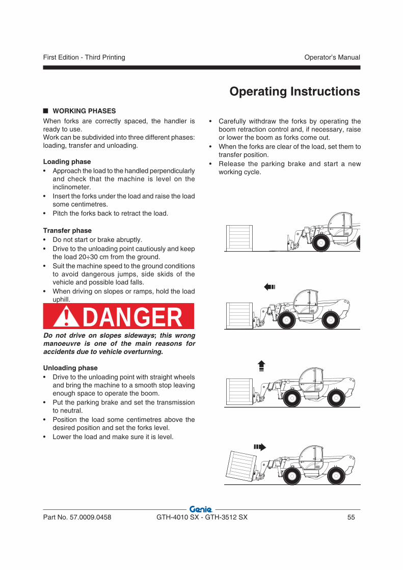
• Carefully withdraw the forks by operating the boom retraction control and, if necessary, raise or lower the boom as forks come out.
• When the forks are clear of the load, set them to transfer position.
• Release the parking brake and start a new working cycle.
WORKING PHASESWhen forks are correctly spaced, the handler is ready to use.Work can be subdivided into three different phases: loading, transfer and unloading.
Loading phase• Approach the load to the handled perpendicularly
and check that the machine is level on the inclinometer.
• Insert the forks under the load and raise the load some centimetres.
• Pitch the forks back to retract the load.
Transfer phase• Do not start or brake abruptly.• Drive to the unloading point cautiously and keep
the load 20÷30 cm from the ground.• Suit the machine speed to the ground conditions
to avoid dangerous jumps, side skids of the vehicle and possible load falls.
• When driving on slopes or ramps, hold the load uphill.
DANGERDo not drive on slopes sideways; this wrong manoeuvre is one of the main reasons for accidents due to vehicle overturning.
Unloading phase• Drive to the unloading point with straight wheels
and bring the machine to a smooth stop leaving enough space to operate the boom.
• Put the parking brake and set the transmission to neutral.
• Position the load some centimetres above the desired position and set the forks level.
• Lower the load and make sure it is level.
Operating Instructions
Part No. 57.0009.0458 GTH-4010 SX - GTH-3512 SX 55
Operator’s ManualFirst Edition - Third Printing
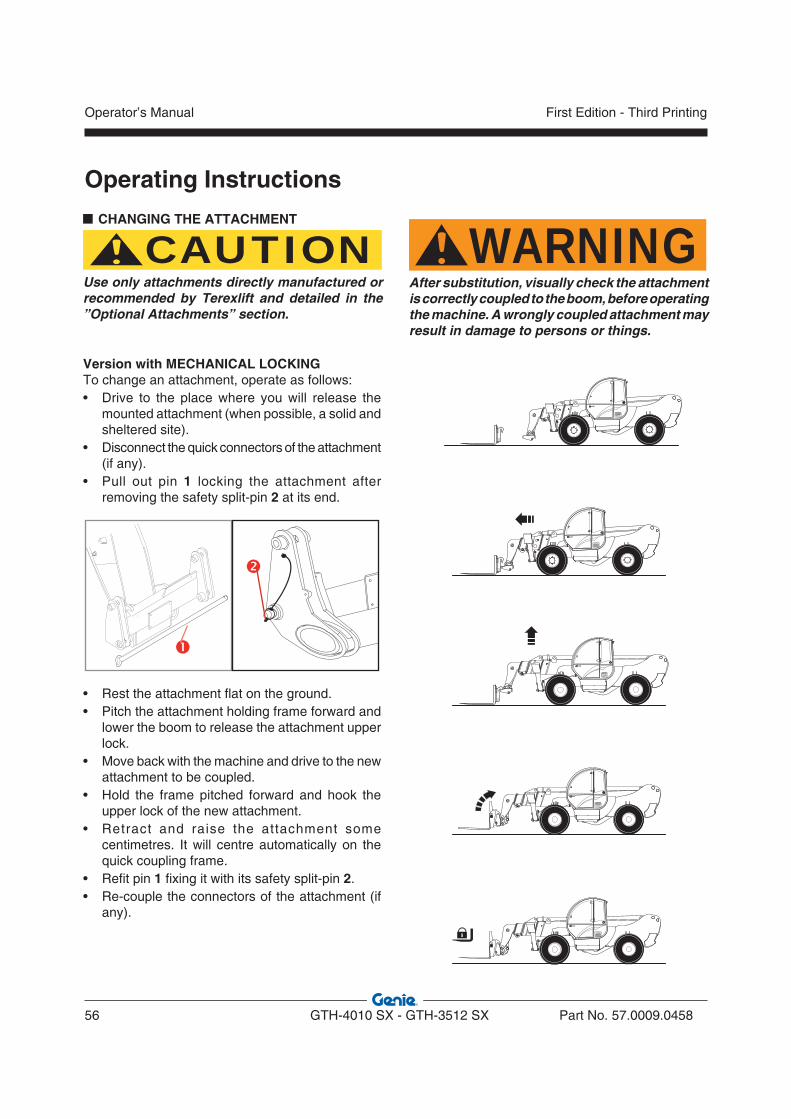
CHANGING THE ATTACHMENT
CAUTIONUse only attachments directly manufactured or recommended by Terexlift and detailed in the ”Optional Attachments” section.
WARNINGAfter substitution, visually check the attachment is correctly coupled to the boom, before operating the machine. A wrongly coupled attachment may result in damage to persons or things.
Version with MECHANICAL LOCKINGTo change an attachment, operate as follows:• Drive to the place where you will release the
mounted attachment (when possible, a solid and sheltered site).
• Disconnect the quick connectors of the attachment (if any).
• Pull out pin 1 locking the attachment after removing the safety split-pin 2 at its end.
• Rest the attachment flat on the ground.• Pitch the attachment holding frame forward and
lower the boom to release the attachment upper lock.
• Move back with the machine and drive to the new attachment to be coupled.
• Hold the frame pitched forward and hook the upper lock of the new attachment.
• Retract and raise the attachment some centimetres. It will centre automatically on the quick coupling frame.
• Refit pin 1 fixing it with its safety split-pin 2.• Re-couple the connectors of the attachment (if
any).
Operating Instructions
Operator’s Manual
56 GTH-4010 SX - GTH-3512 SX Part No. 57.0009.0458
First Edition - Third Printing
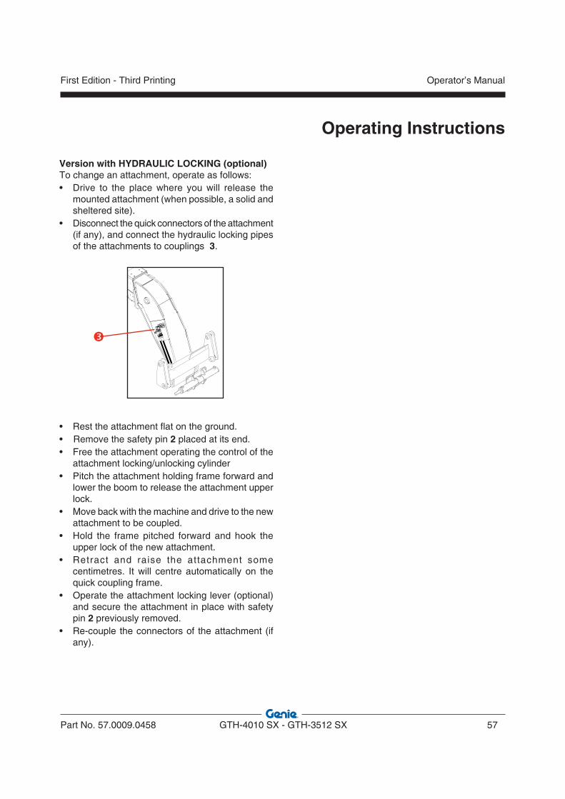
Version with HYDRAULIC LOCKING (optional)To change an attachment, operate as follows:• Drive to the place where you will release the
mounted attachment (when possible, a solid and sheltered site).
• Disconnect the quick connectors of the attachment (if any), and connect the hydraulic locking pipes of the attachments to couplings 3.
• Rest the attachment flat on the ground.• Remove the safety pin 2 placed at its end.• Free the attachment operating the control of the
attachment locking/unlocking cylinder• Pitch the attachment holding frame forward and
lower the boom to release the attachment upper lock.
• Move back with the machine and drive to the new attachment to be coupled.
• Hold the frame pitched forward and hook the upper lock of the new attachment.
• Retract and raise the attachment some centimetres. It will centre automatically on the quick coupling frame.
• Operate the attachment locking lever (optional) and secure the attachment in place with safety pin 2 previously removed.
• Re-couple the connectors of the attachment (if any).
Operating Instructions
Part No. 57.0009.0458 GTH-4010 SX - GTH-3512 SX 57
Operator’s ManualFirst Edition - Third Printing

Intentionally blank page
Operator’s Manual
58 GTH-4010 SX - GTH-3512 SX Part No. 57.0009.0458
First Edition - Third Printing
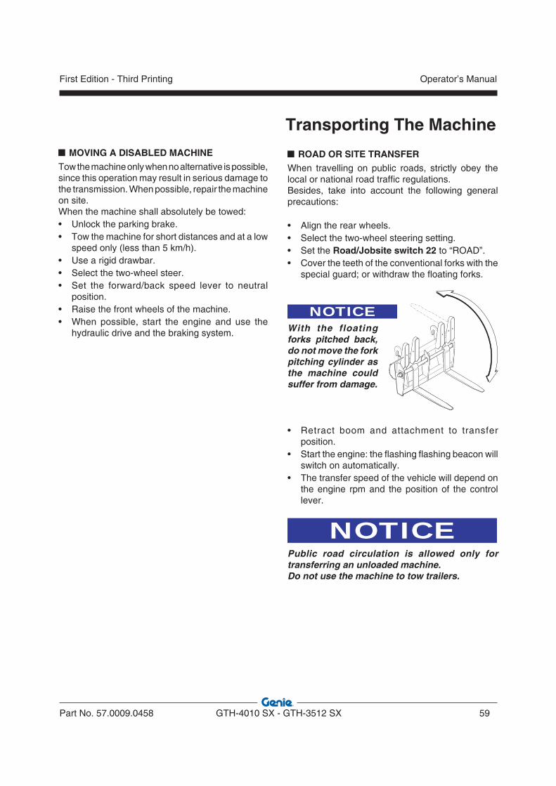
MOVING A DISABLED MACHINETow the machine only when no alternative is possible, since this operation may result in serious damage to the transmission. When possible, repair the machine on site.When the machine shall absolutely be towed:• Unlock the parking brake.• Tow the machine for short distances and at a low
speed only (less than 5 km/h).• Use a rigid drawbar.• Select the two-wheel steer.• Set the forward/back speed lever to neutral
position.• Raise the front wheels of the machine. • When possible, start the engine and use the
hydraulic drive and the braking system.
Transporting The Machine
ROAD OR SITE TRANSFERWhen travelling on public roads, strictly obey the local or national road traffic regulations.Besides, take into account the following general precautions:
• Align the rear wheels.• Select the two-wheel steering setting.• Set the Road/Jobsite switch 22 to “ROAD”.• Cover the teeth of the conventional forks with the
special guard; or withdraw the floating forks.
NOTICEWith the floating forks pitched back, do not move the fork pitching cylinder as the machine could suffer from damage.
• Retract boom and attachment to transfer position.
• Start the engine: the flashing flashing beacon will switch on automatically.
• The transfer speed of the vehicle will depend on the engine rpm and the position of the control lever.
NOTICEPublic road circulation is allowed only for transferring an unloaded machine.Do not use the machine to tow trailers.
Part No. 57.0009.0458 GTH-4010 SX - GTH-3512 SX 59
Operator’s ManualFirst Edition - Third Printing

Transporting The Machine LIFTING THE MACHINE
When the machine shall be lifted, use only means having a suitable capacity. The characteristic data are detailed in the relevant chapter of this manual and on the identification plate.
For the machine lifting, anchor the chains to the special lugs on the machine (marked with the decal below).
09.4618.0916
TRANSPORTING THE MACHINE ON OTHER VEHICLES
To transport the machine on another vehicle, follow the steps below:• Ensure ramps are correctly positioned.• Retraact the boom to transfer position.• Carefully drive the machine onto the transporting
vehicle.• Put the parking brake and rest the attachment flat
on the vehicle platform.• Ensure the overall dimensions do not exceed the
allowed limits.• Shut the engine down and close the driving cab
of the machine.• Secure the machine to the vehicle platform by
wheel-chocks.• Anchor the machine to the transporter's platform
by fixing the chains to the special eyebolts A on the chassis.
�
Operator’s Manual
60 GTH-4010 SX - GTH-3512 SX Part No. 57.0009.0458
First Edition - Third Printing
Transporting The Machine PARKING AND STORAGE
Short inactivityAlways park the machine in a safe way after a working day, a shift and at night.Take all precautions to prevent damage to those persons who will approach the machine while stationary:• Park the machine so that it does not hinder other
operations.• Lower the boom fitted with attachment on the
ground.• Disengage the transmission and put the parking
brake.• Remove the key from the ignition switch and lock
the cab door.
CAUTIONLeaving a battery connected can result in shorts and, as a consequence, in a fi re.
Machine storageIn case of extended inactivity of the machine, follow the above precautions. Additionally:• Wash the machine thoroughly. For a better
cleaning, remove grills and protection casings. • Carefully dry all machine parts by blowing some
compressed air.• Lubricate the machine thoroughly.• Do a walk-around inspection and replace any
worn or damaged part.• Re-paint any worn or damaged part.• Remove the battery, smear its terminals with
vaseline and store it in a dry place. Battery can be used for other purposes. Otherwise, periodically check its charge level.
• Refuel the tank to prevent internal oxidation.• Store the machine in a sheltered and well-
ventilated place.• Start the engine for about 10 minutes at least
once a month.• When weather is particularly cold, empty the
radiator.
NOTICEAlways remember that the ordinary maintenance must be carried out even during the machine inactivity. Pay particular attention to the fluid levels and to those parts subject to ageing. Before re-starting the machine, carry out an extraordinary maintenance and carefully check all mechanical, hydraulic and electrical components.
Part No. 57.0009.0458 GTH-4010 SX - GTH-3512 SX 61
Operator’s ManualFirst Edition - Third Printing
Transporting The Machine CLEANING AND WASHING THE MACHINE
Clean the machine in accordance with the following instructions:• Remove any oil or grease traces with a dry
solvent or a volatile mineral alcohol• Before assembling a new part, remove any
protection product (rust-preventer, grease, wax etc.).
• Remove any trace of rust from metal parts with some emery cloth before smearing the part with a protection product (rust-preventer, paint, oil etc.).
NOTICEDo not use water at high pressure for washing the machine and especially the main valve, the solenoid valves and electrical parts.
External washingBefore washing the machine, check that the engine is shut down and the doors and windows are closed.Do not, at any times, use fuel to clean the machine. Use water or some steam. In cold climates, dry the locks after washing or smear them with an antifreeze.Before using the machine again, check its conditions.Internal washingWash the machine interior with some water and a sponge. Do not use water at high pressure. After washing, dry with a clean cloth.Washing the engineBefore washing the engine, protect the air intake filter to prevent water from entering the circuit.
NOTICEIf the machine shall be used in a marine or equivalent environment, protect it against salt deposits with an adequate treatment against saltiness to prevent rust formation.
MACHINE DISPOSAL
PROTECT THEENVIRONMENT
At the end of the machine life, call in a specialised firm to dispose of it in compliance with the local or national regulations.
Battery disposal
PROTECT THEENVIRONMENT
Used lead-acid batteries cannot be disposed of as normal industrial solid wastes. Because of the presence of harmful substances, they must be collected, eliminated and/or recycled in accordance with the laws of the UE.Used batteries must be kept in a dry and confined place. Make sure the battery is dry and the cell plugs are tight. Place a sign on the battery to warn of not using it. If before disposal the battery is left in the open air, it will be necessary to dry, smear the box and the elements with a coat of grease and tighten the plugs. Do not rest the battery on the ground; it is always advisable to rest it on a pallet and cover it. The disposal of batteries shall be as rapid as possible.
Operator’s Manual
62 GTH-4010 SX - GTH-3512 SX Part No. 57.0009.0458
First Edition - Third Printing

Observe and obey:* The operator can only perform
the rout ine maintenance operations envisaged in this manual.
* Schedu led ma in tenance procedures shall be completed by qualified technical personnel according to the manufacturer’s specifications.
Maintenance symbol legend:
The following symbols are used in this manual to help you understand better the instructions provided. When one or more symbols appear at the beginning of a maintenance procedure, they indicate the following:
Indicates that tools are required to perform the procedure.
Indicates that new parts are required to perform the procedure. Indicates that a cold engine is required to perform the procedure.
Indicates the time interval for the maintenance jobs expressed in working hours.
Maintenance INTRODUCTION
A thorough and regular maintenance keeps the machine in a safe and efficient working condition.
For this reason, it is advisable to wash, grease and service the machine properly, especially after having worked under particular conditions (muddy or dusty environments, heavy operations, etc.).
Always ensure all machine components are in good condition. Check for oil leaks or loosening of guards, and make sure that the safety devices are efficient. In case of defects, find and rectify them before using the machine again.
Not respecting the ordinary maintenance schedule of this manual automatically voids TEREXLIFT warranty.
NOTICEFor the engine maintenance, please refer to the specific Operator handbook supplied with the machine.
SERVICE INTERVALRunning-in ____________________________
Ordinary ______________________________
Part No. 57.0009.0458 GTH-4010 SX - GTH-3512 SX 63
Operator’s ManualFirst Edition - Third Printing

LUBRICANTS - HEALTH AND SAFETY PRECAUTIONS
HealthA prolonged skin contact with oil can cause irritation. Use rubber gloves and protective goggles. After handling oil, carefully wash your hands with soap and water.
StorageAlways keep lubricants in a closed place, out of the children’s reach. Never store lubricants on the open air and without a label indicating their contents.
DisposalNew or exhausted oil is always polluting! Never drain oil on the ground. Store new oil in a suitable warehouse. Pour exhausted oil into cans and deliver them to specialised firms for disposal.
Oil leaksIn case of accidental oil leaks, cover with sand or type-approved granulate. Then scrape off and dispose of it as chemical waste.
Maintenance
First aidEyes : In case of accidental contact with
the eyes, wash with fresh water. If the irritation persists, seek medical advice.
Intake : In case of oil intake, do not induce vomiting, but seek medical advice.
Skin : In case of a prolonged contact, wash with soap and water.
FireIn case of fire, use carbon dioxide, dry chemical or foam extinguishers. Do not use water.
Operator’s Manual
64 GTH-4010 SX - GTH-3512 SX Part No. 57.0009.0458
First Edition - Third Printing

Maintenance ORDINARY MAINTENANCE
A wrong or neglected maintenance can result in possible risks for both operator and bystanders. Make sure maintenance and lubrication are carried out according to the manufacturer’s instructions to keep the machine safe and efficient.The maintenance interventions are based on the machine working hours. Regularly check the hour-meter and keep it in good conditions to define the maintenance intervals correctly. Make sure any defect detected during the maintenance is promptly rectified before using the machine.
CAUTIONAll "" marked operations must be carried out by a skilled technician.
During the first 10 working hours1. Check the oil level within reduction gears, power
divider and differential gears2. Regularly check the tightening of the wheel
bolts3. Check the tightening of all bolts and nuts4. Check the couplings for oil leaks
Within the first 100 working hours1. Change the oil of the differential casing, the
wheel reducer and the power divider gearbox.
Every 10 working hours or daily1. Check the engine oil level.2. Clean the air suction filter.3. Check the engine coolant level.4. Clean the radiator, if necessary.5. Check the hydraulic oil level in the tank.6. Check the greasing of the boom section pads.7. Grease the attachment holding frame.8. Grease all joints of the boom, the rear axle shaft
joint, the transmission shafts, the front and rear axles and any equipment of the machine.
9. Check the efficiency of the overload warning system.
10. Check the efficiency of the lighting electric system.
11. Check the efficiency of braking system and parking brake.
12. Check the efficiency of the steering selection system.
13. Check the efficiency of the fork balancing system.
14. Make sure the safety devices installed are in efficient working order.
15. Check or re-sequence the boom telescopes.
Every 50 working hours or weeklyJobs to be done in addition to those above
1. Check the tension of the alternator belt.2. Check the tyre inflation.3. Check the tightening of the wheel nuts.4. Check the tightening of the Cardan shaft
screws.5. Clean the radiator fins.
Every 250 working hours or monthlyJobs to be done in addition to those above
1. Check the oil level in the front and rear differential gears.
2. Check the oil level in the four wheel reduction gears.
3. Check the main filtering element of the engine air filter. Replace, if necessary.
Part No. 57.0009.0458 GTH-4010 SX - GTH-3512 SX 65
Operator’s ManualFirst Edition - Third Printing

4. Check the clamping of the cableheads to the battery terminals.
5. Check the air suction hose between engine and filter.
6. Check the cylinder chromium-plated rods.7. Check the hydraulic lines are not worn because
of rubbing against the frame or other mechanical components.
8. Check the electric cables do not rub against the frame or other mechanical components.
9. Check the wear of the sliding pads of the boom sections.
10. Adjust the play of the sliding pads of the boom sections.
11. Remove any grease from the boom, then re-grease the sliding parts of the boom sections.
12. Check the level of the battery electrolyte.
Every 3 working monthsJobs to be done in addition to those above
1. Check the efficiency of the block valves.
Every 500 working hours or every six monthsJobs to be done in addition to those above
1. Visually check the smoke quantity evacuated from the engine exhaust.
2. Check the tightening of the engine fixing screws.
3. Check the tightening of the cab fixing screws. 4. Check the backlash between pins and bushings
in all joints.5. Change the hydraulic oil filter in the tank.6. Have the hydraulic system checked by a skilled
technician.7. Change the main cartridge of the engine air
filter.8. Renew the cartridge of the engine oil filter and
the fuel filter.
Maintenance
9. Change the oil of the front and rear differential casings.
Every 500 working hours or yearlyJobs to be done in addition to those above
1. Change the engine oil and renew the fuel filter.
Every 1000 working hours or yearlyJobs to be done in addition to those above
1. Change the safety element of engine air filter.2. Change the oil in the power divider gearbox.3. Change the oil in the four wheel reduction
gears.4. Change the hydraulic oil.
Every 2000 working hours or every two yearsJobs to be done in addition to those above
1. Change the engine coolant.
At 6000 hours or 5 years and, subsequently, every 2 yearsJobs to be done in addition to those above
1. Check that the structure is intact paying a special attention to the welded supporting joints and the boom pins.
Operator’s Manual
66 GTH-4010 SX - GTH-3512 SX Part No. 57.0009.0458
First Edition - Third Printing

Maintenance OIL CHANGE SCHEDULE
* whichever occurs fi rst.
JobOperating
hours *Service
interval *Oil type
Engine
Oil level check 10 daily SHELL RIMULA 15W-40(API CH-4/CG-4/CF-4/CF; ACEA E3; MB228.3)
First change 500 -
Subsequent changes 500 yearly
Axles and powerdivider
gearbox
Oil level check 250 monthly TRACTORENAULT THFI 208 LF SAE 80W; API GL4 / FORD M2C 86B; MASSEY FERGU-SON M 1135
First change - -
Subsequent changes 1000 yearly
Hydraulic oil
Oil level check 10 daily SHELL TELLUS T 46DENISON HF-1, DIN 51524 part 2 & 3
First change - -
Subsequent changes 1000 yearly
Part No. 57.0009.0458 GTH-4010 SX - GTH-3512 SX 67
Operator’s ManualFirst Edition - Third Printing

Maintenance
MAINTENANCE INTERVENTIONS
WARNINGAll maintenance interventions must be carried out with engine stopped, parking brake engaged, working attachments flat on the ground and gear lever in neutral.
WARNINGWhen raising a component for maintenance purposes, secure it in a safe way before any maintenance intervention.
WARNINGAny intervention on the hydraulic circuit must be carried out by skilled personnel.The hydraulic circuit of this machine is fitted with pressure accumulators. You and others could be seriously injured if accumulators are not completely depressurised.For this purpose, shut the engine down and step on the brake pedal 8/10 times.
WARNINGBefore any operation on hydraulic lines or components, make sure there is no residual pressure. For this purpose, stop the engine, engage the parking brake and operate the control levers of the main valve in both working directions (alternately) to depressurise the hydraulic circuit.
CAUTIONHigh pressure lines must be replaced by qualified personnel only. Any foreign matters entering the closed circuit may result in a sudden deterioration of the transmission.
CAUTIONThe qualified staff charged with the maintenance of the hydraulic circuit must clean all areas around with care before any intervention.
PROTECT THEENVIRONMENT
The handling and disposing of used oils can be ruled by local or national regulations. Address to authorised centres.
Operator’s Manual
68 GTH-4010 SX - GTH-3512 SX Part No. 57.0009.0458
First Edition - Third Printing

Maintenance ACCESS TO THE ENGINE COMPARTMENT
For any operation within the engine compartment, open the protection bonnet.The bonnet is equipped with pneumatic shock absorbers which unburdens and hold the bonnet in raised position. To open the bonnet:• Shut the engine down and put the parking
brake.• Turn the key to unlock and open the bonnet.
CAUTIONTake a l l precaut ions when approaching the engine compartment. Some parts of the engine may be very hot. Always use protective gloves.
Part No. 57.0009.0458 GTH-4010 SX - GTH-3512 SX 69
Operator’s ManualFirst Edition - Third Printing

Maintenance ENGINE AIR FILTER
Clean the engine air filter and replace the elements, when necessary.
1 Cleaning and changing the outer element:
- Shut the engine down and engage the parking brake.
- Unlatch the fasteners A and remove cover B - Pull out the filter cartridge C. - Clean the filter bowl. - Dry clean the cartridge (at max. 6 bar pressure)
and direct the air jet from inside to outside. - Check the filter element for cracks by introducing
a lamp inside. - Refit the cartridge and make sure it is properly
positioned. - Close cover B and lock in place with fasteners
A.
NOTICEAs soon as the warning lamp 11.3 on the cab dashboard switches on, replace the outer element.Never wash the cartridge with water or solvents.
2 Changing the internal element - See step 1 for removing the outer element. - Extract the internal cartridge D. - Clean the filter bowl. - Mount the new element and make sure it is
correctly positioned. - Fit the main filter and the cap as described in
point 1. SERVICE INTERVAL
Running-in _____________________________ None
Cleaning _____________________ Every 10 hours
Outer element change __________Every 500 hours
Inner element change ________ Every 1000 hours
NOTICEThe inner element should be replaced every two times the outer element is replaced.Never wash the cartridge with water or solvents.
�
�
�
�
Operator’s Manual
70 GTH-4010 SX - GTH-3512 SX Part No. 57.0009.0458
First Edition - Third Printing
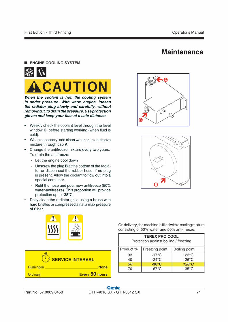
Maintenance ENGINE COOLING SYSTEM
CAUTIONWhen the coolant is hot, the cooling system is under pressure. With warm engine, loosen the radiator plug slowly and carefully, without removing it, to drain the pressure. Use protection gloves and keep your face at a safe distance.
• Weekly check the coolant level through the level window C, before starting working (when fluid is cold).
• When necessary, add clean water or an antifreeze mixture through cap A.
• Change the antifreeze mixture every two years. To drain the antifreeze:
- Let the engine cool down
- Unscrew the plug B at the bottom of the radia-tor or disconnect the rubber hose, if no plug is present. Allow the coolant to flow out into a special container.
- Refit the hose and pour new antifreeze (50% water-antifreeze). This proportion will provide protection up to -38°C.
• Daily clean the radiator grille using a brush with hard bristles or compressed air at a max pressure of 6 bar.
SERVICE INTERVAL
Running-in __________________________ None
Ordinary __________________ Every 50 hours
On delivery, the machine is filled with a cooling mixture consisting of 50% water and 50% anti-freeze.
�
�
TEREX PRO COOLProtection against boiling / freezing
Product % Freezing point Boiling point
33405070
-17°C-24°C-36°C-67°C
123°C126°C128°C135°C
�
Part No. 57.0009.0458 GTH-4010 SX - GTH-3512 SX 71
Operator’s ManualFirst Edition - Third Printing
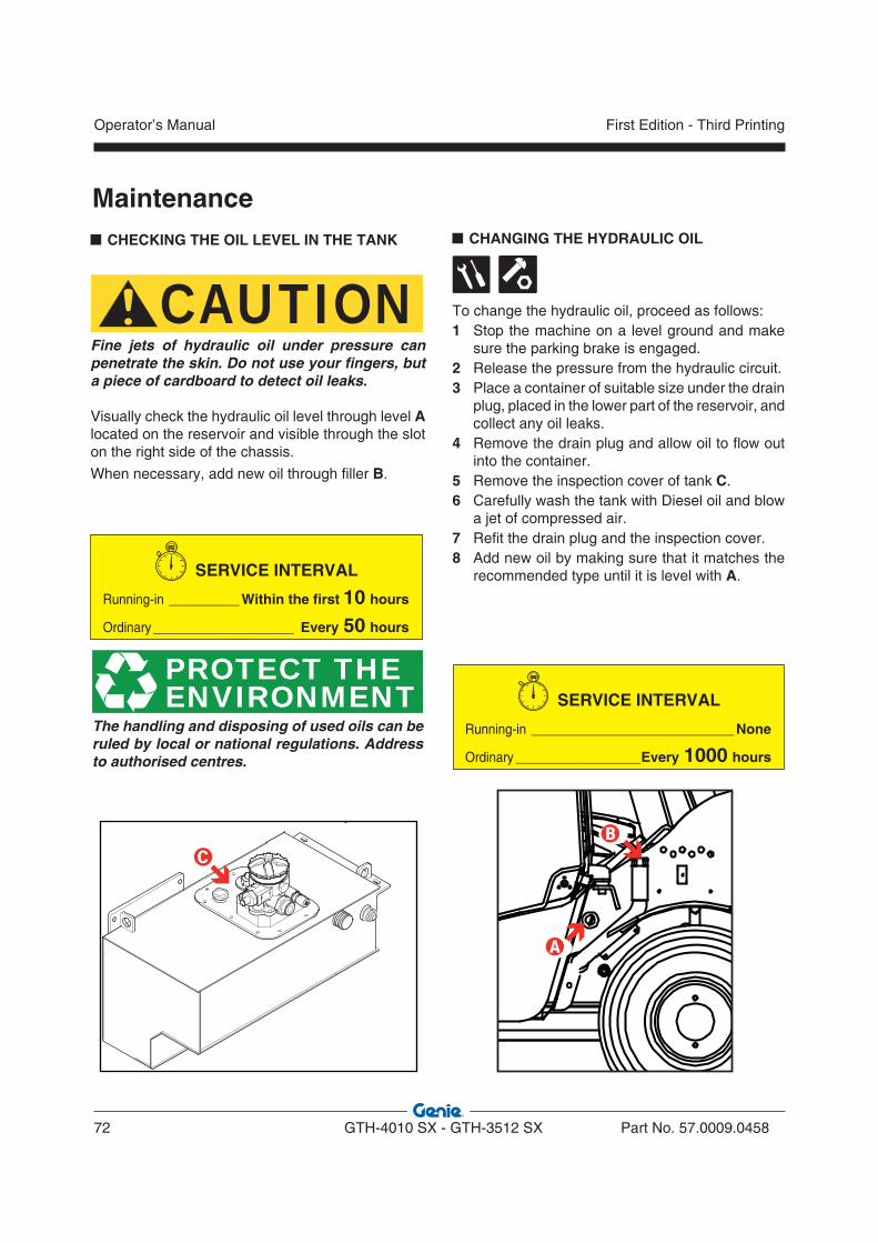
Maintenance CHECKING THE OIL LEVEL IN THE TANK
CAUTIONFine jets of hydraulic oil under pressure can penetrate the skin. Do not use your fingers, but a piece of cardboard to detect oil leaks.
Visually check the hydraulic oil level through level A located on the reservoir and visible through the slot on the right side of the chassis.
When necessary, add new oil through filler B.
SERVICE INTERVAL
Running-in _________ Within the first 10 hours
Ordinary __________________ Every 50 hours
PROTECT THEENVIRONMENT
The handling and disposing of used oils can be ruled by local or national regulations. Address to authorised centres.
�
CHANGING THE HYDRAULIC OIL
To change the hydraulic oil, proceed as follows:1 Stop the machine on a level ground and make
sure the parking brake is engaged.2 Release the pressure from the hydraulic circuit.3 Place a container of suitable size under the drain
plug, placed in the lower part of the reservoir, and collect any oil leaks.
4 Remove the drain plug and allow oil to flow out into the container.
5 Remove the inspection cover of tank C. 6 Carefully wash the tank with Diesel oil and blow
a jet of compressed air.7 Refit the drain plug and the inspection cover. 8 Add new oil by making sure that it matches the
recommended type until it is level with A.
SERVICE INTERVAL
Running-in __________________________ None
Ordinary ________________Every 1000 hours
�
�
Operator’s Manual
72 GTH-4010 SX - GTH-3512 SX Part No. 57.0009.0458
First Edition - Third Printing
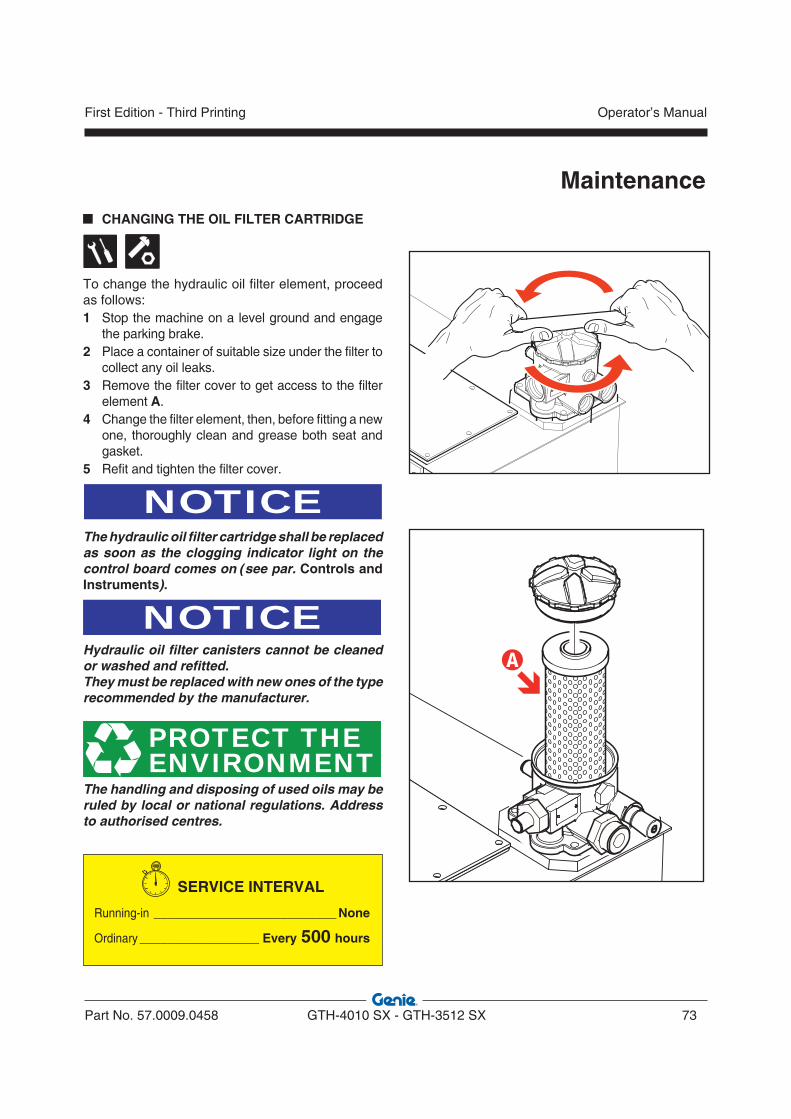
Maintenance CHANGING THE OIL FILTER CARTRIDGE
To change the hydraulic oil filter element, proceed as follows:1 Stop the machine on a level ground and engage
the parking brake.2 Place a container of suitable size under the filter to
collect any oil leaks.3 Remove the filter cover to get access to the filter
element A. 4 Change the filter element, then, before fitting a new
one, thoroughly clean and grease both seat and gasket.
5 Refit and tighten the filter cover.
NOTICEThe hydraulic oil filter cartridge shall be replaced as soon as the clogging indicator light on the control board comes on (see par. Controls and Instruments).
NOTICEHydraulic oil filter canisters cannot be cleaned or washed and refitted. They must be replaced with new ones of the type recommended by the manufacturer.
PROTECT THEENVIRONMENT
The handling and disposing of used oils may be ruled by local or national regulations. Address to authorised centres.
SERVICE INTERVAL
Running-in __________________________ None
Ordinary _________________ Every 500 hours
�
Part No. 57.0009.0458 GTH-4010 SX - GTH-3512 SX 73
Operator’s ManualFirst Edition - Third Printing
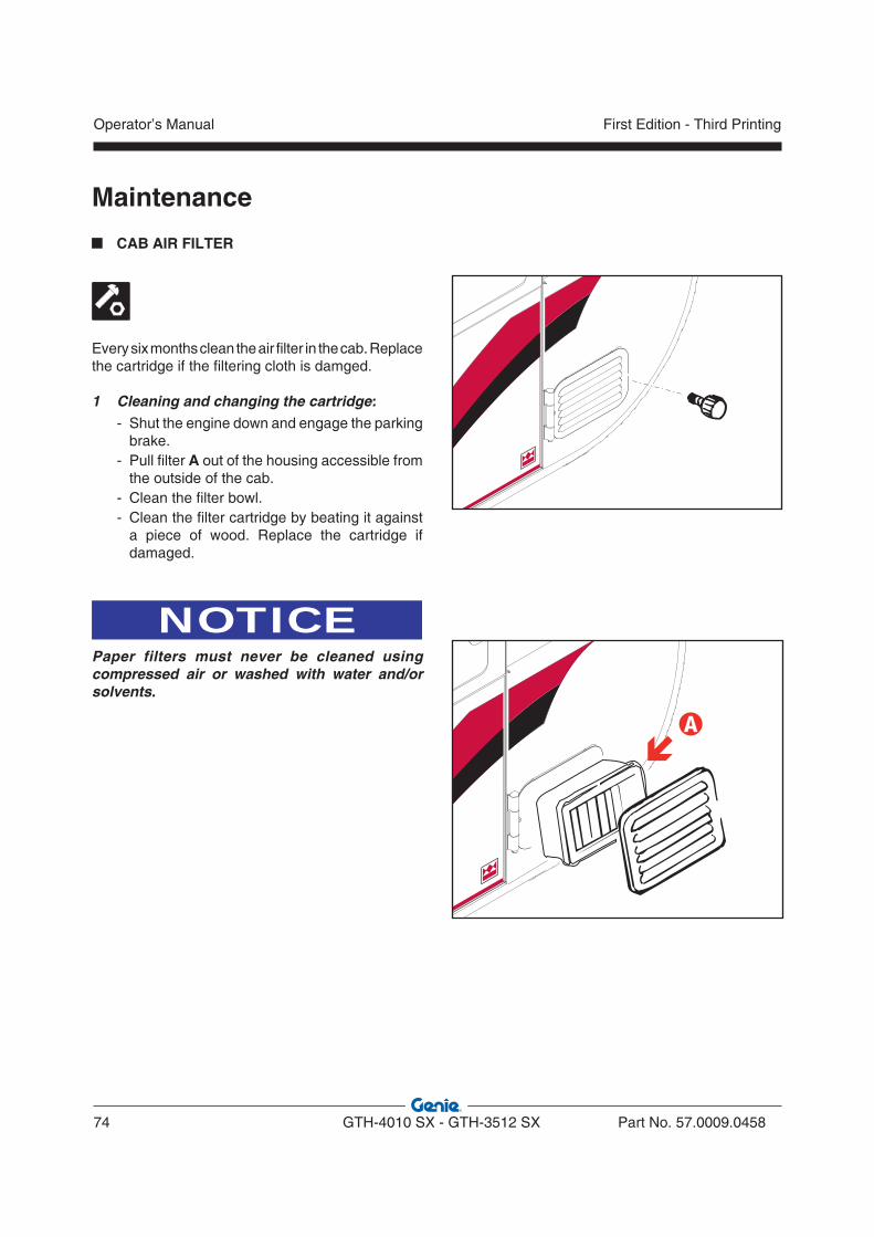
Maintenance
CAB AIR FILTER
Every six months clean the air filter in the cab. Replace the cartridge if the filtering cloth is damged.
1 Cleaning and changing the cartridge: - Shut the engine down and engage the parking
brake. - Pull filter A out of the housing accessible from
the outside of the cab. - Clean the filter bowl. - Clean the filter cartridge by beating it against
a piece of wood. Replace the cartridge if damaged.
NOTICEPaper filters must never be cleaned using compressed air or washed with water and/or solvents.
�
Operator’s Manual
74 GTH-4010 SX - GTH-3512 SX Part No. 57.0009.0458
First Edition - Third Printing

Maintenance OIL LEVEL IN THE DIFFERENTIAL GEARS
To check the oil level in the front and rear differential gears:
• Stop the machine on a level ground and engage the parking brake.
• Loosen level plug and check if oil is level with the hole.
• If necessary, top-up through hole until oil comes out from hole .
• Refit and tighten plugs and .
To change the oil:• Place a container of suitable size under drain
plug .
• Loosen the drain plug, the level plug and the filler and allow oil to flow out from the reduction gear.
• Refit and tighten drain plug .• Add new oil through the filler until it is level with
hole .
• Refit and tighten plugs and .
OIL LEVEL IN THE (front/rear) WHEEL REDUCTION GEARS
To check the oil level within the wheel reduction gears:• Stop the machine on a level ground and ensure
the parking brake is engaged and plug finds on the horizontal axis.
• Clean the plug all around, then remove it and check if oil is level with the hole.
• If necessary, add new oil through hole until it is level.
• Refit the plug.
To change the oil:• Stop the machine and ensure the plug is oriented
along the vertical axis.• Place a container of suitable size under the
reduction gear plug.• Unscrew plug and drain any oil from the reduction
gear.• Rotate the wheel by 90° until the plug finds again
on the horizontal axis.
• Add new oil through hole .• Refit and tighten plug.
SERVICE INTERVAL
Running-in _________ Within the first 10 hours
Ordinary _________________ Every 250 hours
SERVICE INTERVAL
Running-in _________ Within the first 10 hours
Ordinary _________________ Every 250 hours
Filling plug
Drain plug
Level plug
Part No. 57.0009.0458 GTH-4010 SX - GTH-3512 SX 75
Operator’s ManualFirst Edition - Third Printing

Maintenance
OIL LEVEL IN THE POWER DIVIDER GEARBOX
To check the oil level in the power diver gearbox:• Stop the machine on a level ground and make
sure the parking brake is engaged.
• Clean level plug all around.• Remove the plug and check if oil is level with the
hole.
• When necessary, add new oil through plug until it is level with the hole.
• Refit and tighten the plug.
To change the oil:• Place a container of suitable size under the drain
plug.
• Remove the plug .
• Remove the drain plug and empty the power divider gearbox.
• Refit and tighten the drain plug .
• Pour in new oil through the filler placed at the top of the reduction gear of the power divider. Stop when oil is level with hole .
• Refit and tighten plug .
SERVICE INTERVAL
Running-in _________ Within the first 10 hours
Ordinary _________________ Every 250 hours
Filling plug
Drain plug
Operator’s Manual
76 GTH-4010 SX - GTH-3512 SX Part No. 57.0009.0458
First Edition - Third Printing
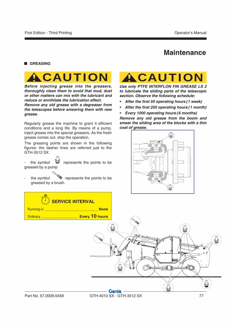
Maintenance GREASING
CAUTIONBefore injecting grease into the greasers, thoroughly clean them to avoid that mud, dust or other matters can mix with the lubricant and reduce or annihilate the lubrication effect.Remove any old grease with a degreaser from the telescopes before smearing them with new grease.
Regularly grease the machine to grant it efficient conditions and a long life. By means of a pump, inject grease into the special greasers. As the fresh grease comes out, stop the operation.
The greasing points are shown in the following figures: the dasher lines are referred just to the GTH-3512 SX.
- the symbol represents the points to be greased by a pump
- the symbol represents the points to be greased by a brush.
SERVICE INTERVAL
Running-in __________________________ None
Ordinary __________________ Every 10 hours
CAUTIONUse only PTFE INTERFLON FIN GREASE LS 2 to lubricate the sliding parts of the telescopic section. Observe the following schedule:• After the first 50 operating hours (1 week)• After the first 250 operating hours (1 month)• Every 1000 operating hours (6 months)Remove any old grease from the boom and smear the sliding area of the blocks with a thin coat of grease.
Part No. 57.0009.0458 GTH-4010 SX - GTH-3512 SX 77
Operator’s ManualFirst Edition - Third Printing
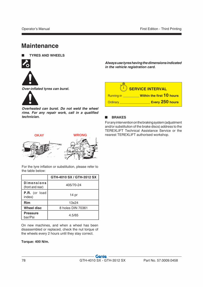
Maintenance TYRES AND WHEELS
Over-inflated tyres can burst.
Overheated can burst. Do not weld the wheel rims. For any repair work, call in a qualified technician.
Always use tyres having the dimensions indicated in the vehicle registration card.
SERVICE INTERVAL
Running-in _________ Within the first 10 hours
Ordinary _________________ Every 250 hours
For the tyre inflation or substitution, please refer to the table below:
GTH-4010 SX / GTH-3512 SX
D i m e n s i o n s (front and rear)
405/70-24
P.R. (or load index)
14 pr
Rim 13x24
Wheel disc 8 holes DIN 70361
Pressure bar/Psi
4.5/65
RI RON OKAY WRONG
BRAKESFor any intervention on the braking system (adjustment and/or substitution of the brake discs) address to the TEREXLIFT Technical Assistance Service or the nearest TEREXLIFT authorised workshop.
On new machines, and when a wheel has been disassembled or replaced, check the nut torque of the wheels every 2 hours until they stay correct.
Torque: 400 N/m.
Operator’s Manual
78 GTH-4010 SX - GTH-3512 SX Part No. 57.0009.0458
First Edition - Third Printing
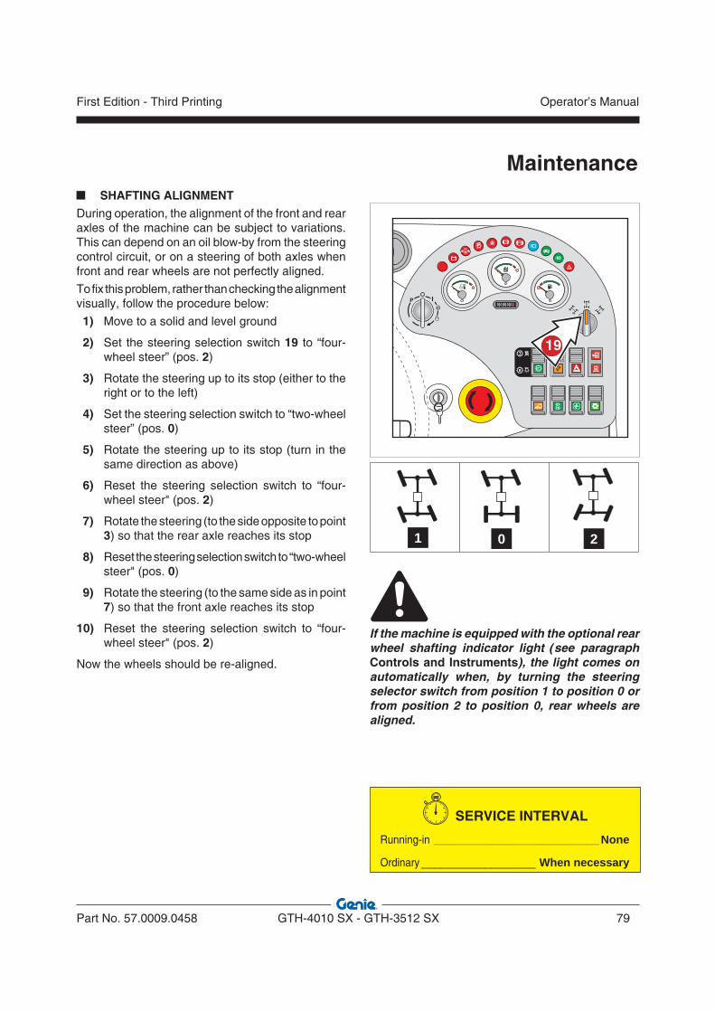
Maintenance SHAFTING ALIGNMENT
During operation, the alignment of the front and rear axles of the machine can be subject to variations. This can depend on an oil blow-by from the steering control circuit, or on a steering of both axles when front and rear wheels are not perfectly aligned.
To fix this problem, rather than checking the alignment visually, follow the procedure below:
1) Move to a solid and level ground
2) Set the steering selection switch 19 to “four-wheel steer” (pos. 2)
3) Rotate the steering up to its stop (either to the right or to the left)
4) Set the steering selection switch to “two-wheel steer” (pos. 0)
5) Rotate the steering up to its stop (turn in the same direction as above)
6) Reset the steering selection switch to “four-wheel steer" (pos. 2)
7) Rotate the steering (to the side opposite to point 3) so that the rear axle reaches its stop
8) Reset the steering selection switch to “two-wheel steer" (pos. 0)
9) Rotate the steering (to the same side as in point 7) so that the front axle reaches its stop
10) Reset the steering selection switch to “four-wheel steer" (pos. 2)
Now the wheels should be re-aligned.
SERVICE INTERVAL
Running-in __________________________ None
Ordinary __________________ When necessary
P
19
0 21
If the machine is equipped with the optional rear wheel shafting indicator light (see paragraph Controls and Instruments), the light comes on automatically when, by turning the steering selector switch from position 1 to position 0 or from position 2 to position 0, rear wheels are aligned.
Part No. 57.0009.0458 GTH-4010 SX - GTH-3512 SX 79
Operator’s ManualFirst Edition - Third Printing

Maintenance ADJUSTING THE SLIDING PADS OF THE BOOM
SECTIONS
Any boom section is fitted with adjustable pads located on the four sides of the profile. These pads are secured to both fixed and mobile part of every section.
All pads can be adjusted by the special shims supplied by TEREXLIFT upon demand.
Adjusting the pads:
• Remove or loosen the screws fixing the pads in relation to type of shims used (with or without slots).
• Fit the necessary amount of shims.• If the residual thickness of the pad is insufficient
or near the maximum wearing limit, renew the pad.
• Tighten the screws fixing the pads at the recommended torque (see below). Use a dynamometric wrench.
Tightening torques of the pad screws in relation to the screw diameter Screws M10 Nm 30
Screws M14 Nm 50
Tightening torques higher than those recom-mended can cause the break of the pad or of the locking threaded bush.
CAUTIONPads must compulsorily be replaced if the residual thickness of the plastic layer with respect to the iron bush fixing the block is equal or inferior to 1 mm.
SERVICE INTERVAL
Running-in __________________________ None
Ordinary __________________ When necessary
Minimum 1 mm
Max. wearing thickness
Operator’s Manual
80 GTH-4010 SX - GTH-3512 SX Part No. 57.0009.0458
First Edition - Third Printing

Maintenance
RE-SEQUENCING THE TELESCOPIC BOOM (Only for GTH-3512 SX)
If, during normal operation, a change in the boom extended lengths of 150 mm or more is noticed when the boom is retracted, proceed as follows:
1. Fully retract the telescope cylinder and hold the system over relief (approx. 15 seconds); the boom sections should become equal.
If after performing this procedure the boom still remains out of sequence, proceed with the steps below:
2. Move the boom to the zero position, fully retract the boom and hold the retract system over relief for approx. 20 seconds. 3. Raise the boom to approx. 60° and operate the retract function over relief for approx. 20 seconds.4. Lower the fully retracted boom to the lowest angle possible without striking the ground and hold the retract system over relief for approx. 20 seconds.
If, despite these procedures, the boom does not return in sequence, raise the boom to approx. 60°, fully extend and retract it to full stroke and hold the system over relief (approx. 20 seconds) in each direction.
By following these procedures the boom re-sequencing should be correct.
SERVICE INTERVAL
Running-in __________________________ None
Ordinary __________________ When necessary
Part No. 57.0009.0458 GTH-4010 SX - GTH-3512 SX 81
Operator’s ManualFirst Edition - Third Printing
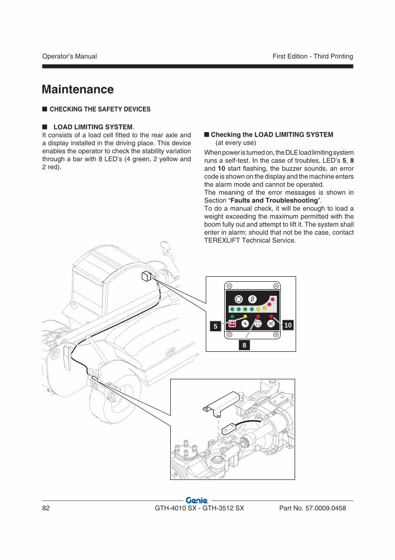
Maintenance
CHECKING THE SAFETY DEVICES
LOAD LIMITING SYSTEM. It consists of a load cell fitted to the rear axle and a display installed in the driving place. This device enables the operator to check the stability variation through a bar with 8 LED’s (4 green, 2 yellow and 2 red).
Checking the LOAD LIMITING SYSTEM
(at every use)
When power is turned on, the DLE load limiting system runs a self-test. In the case of troubles, LED’s 5, 8 and 10 start flashing, the buzzer sounds, an error code is shown on the display and the machine enters the alarm mode and cannot be operated.The meaning of the error messages is shown in Section “Faults and Troubleshooting”.To do a manual check, it will be enough to load a weight exceeding the maximum permitted with the boom fully out and attempt to lift it. The system shall enter in alarm; should that not be the case, contact TEREXLIFT Technical Service.
5
8
10
Operator’s Manual
82 GTH-4010 SX - GTH-3512 SX Part No. 57.0009.0458
First Edition - Third Printing

P
Maintenance
LIMIT SWITCHES on the OUTRIGGERS When the outriggers are lowered to the ground: - the overload warning system changes the
meter scale - the transmission is deactivated
Checking the limit switches of the outriggers (at every use)
To check the limit switches of the outriggers:• Lower the outriggers to the ground and attempt
to engage a gear. If the gear can be engaged, contact the
TEREXLIFT Technical Assistance Service.Proceed on one outrigger at a time.• With the outriggers up, light 8 on the load limiter
panel must be off; with the outriggers down to the ground, the same light must be on. Should it not be the case, contact the TEREXLIFT Technical Service.
WARNINGIf a limit switch is faulty or a lever is deformed, immediately replace the part.
EMERGENCY STOP PUSHBUTTON on the dashboard, to the right of the steering wheel. Pressing down this button stops the engine of the machine.
Before starting work again, find and rectify the relevant causes, then reset the button to neutral position turning it clockwise.
Checking the emergency stop pushbutton (at every use)
To check the efficiency of this pushbutton, simply press it down during a movement. The pressure of the pushbutton shall cause the movement to stop and the engine to shut down.
Part No. 57.0009.0458 GTH-4010 SX - GTH-3512 SX 83
Operator’s ManualFirst Edition - Third Printing

Maintenance
BLOCK VALVES fitted to all CYLINDERSAll machine’s cylinders are equipped with block valves:
• Compensation cylinder
• Lifting cylinder
• Telescopic boom extension cylinder
• Attachment swinging cylinder
• Stabilizing cylinders
DANGERAlways use the lock ring of the lift cylinder (see picture below), when carrying out maintenance on the lift cylinder block valve or, in general, any operation in the area under the boom:
I. Lift and extend the boomII. Unscrew the two screws on the frame (pos. A) to release the ringIII. Put the ring on the lift cylinder rod (pos. B)IV. Lock the ring by tightening the screws provided on the ring.
�
�
Operator’s Manual
84 GTH-4010 SX - GTH-3512 SX Part No. 57.0009.0458
First Edition - Third Printing
To remove the block valves or the cylinders- Lower the boom to the ground in a firm way since
the removal of the block valve or the cylinder can cause an uncontrolled down-movement.
- After refitting the valve or the cylinder, replenish the circuit and eliminate any air before starting working. To eliminate the air from the circuit, move the involved cylinders to end-of-stroke in the two directions (opening/closing. To eliminate the air from the fork balance cylinder, move the boom up and down and tilt the fork plate forwards/back.
WARNINGDo the check of the valves taking all the possible precautionary measures:- Wear safety glasses- Wear safety gloves- Wear safety shoes - Wear suitable working clothes- Use guards against leaks of oil at high
pressure - Do the check in a free space with barriers all
around to keep non-authorised people away- Ensure that the part to be checked is in safe
condition and that the action generated does not result in an uncontrolled movement of the machine.
Checking the block valves (every 3 months)
The piloted blocking valves allow to held the load in position in case of burst of a flexible hose.To check the efficiency of a valve, proceed as follows:• Load a weight near the maximum payload onto
the boom.• Raise the load some centimetres above the
ground (max 10 cm). To check the valve on the telescope extension cylinder move the boom to maximum height and extend it some centimetres.
• Loosen the oil hoses to the cylinder of which you are checking the valve with caution.
• To check the efficiency of the block valves of the outriggers, lower them to the ground and unload the weight of the tyres without raising them. Loosen the cylinder hoses to check the efficiency of the valve.
During the check, the oil will flow out of the hoses and the load shall remain blocked in position. Should that not be the case, the valve must be replaced. Contact TEREXLIFT Technical Service.
Maintenance
Part No. 57.0009.0458 GTH-4010 SX - GTH-3512 SX 85
Operator’s ManualFirst Edition - Third Printing
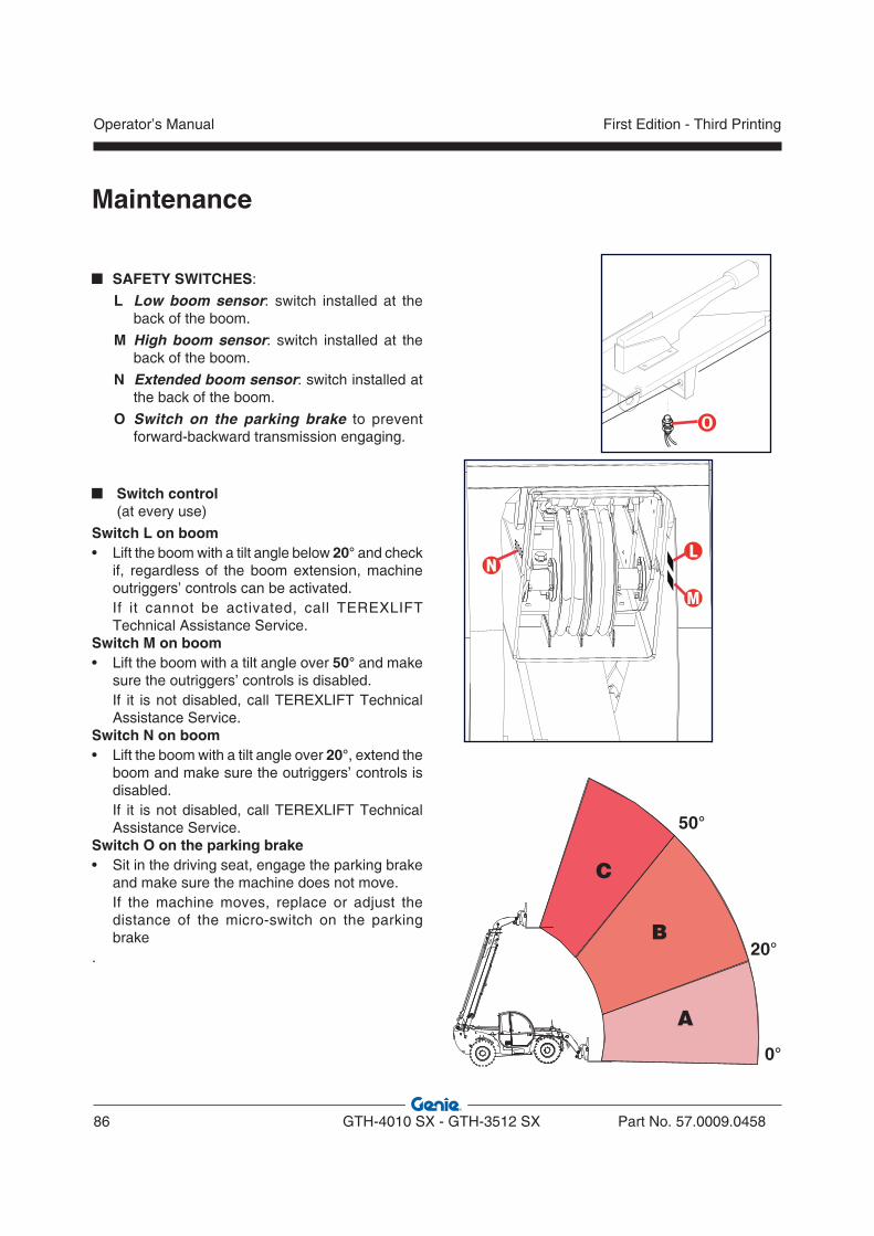
Maintenance
SAFETY SWITCHES:
L Low boom sensor: switch installed at the back of the boom.
M High boom sensor: switch installed at the back of the boom.
N Extended boom sensor: switch installed at the back of the boom.
O Switch on the parking brake to prevent forward-backward transmission engaging.
Switch control (at every use)
Switch L on boom• Lift the boom with a tilt angle below 20° and check
if, regardless of the boom extension, machine outriggers’ controls can be activated.
If it cannot be activated, call TEREXLIFT Technical Assistance Service.
Switch M on boom• Lift the boom with a tilt angle over 50° and make
sure the outriggers’ controls is disabled. If it is not disabled, call TEREXLIFT Technical
Assistance Service.Switch N on boom• Lift the boom with a tilt angle over 20°, extend the
boom and make sure the outriggers’ controls is disabled.
If it is not disabled, call TEREXLIFT Technical Assistance Service.
Switch O on the parking brake• Sit in the driving seat, engage the parking brake
and make sure the machine does not move. If the machine moves, replace or adjust the
distance of the micro-switch on the parking brake
.
�
�
�
A
B
C
50°
20°
0°
Operator’s Manual
86 GTH-4010 SX - GTH-3512 SX Part No. 57.0009.0458
First Edition - Third Printing

Maintenance
Checking the MACHINE START CONTROL (at every use)
Attempt to start the engine with the forward or reverse gear put.
The engine must not start. If the engine starts, contact the TEREXLIFT Technical Service.
Repeat the operation putting first one gear, then the other.
C H E C K I N G T H E S TAT E O F T H E STRUCTURE
Five years or 6000 hours after the fi rst placing into operation of the machine (whichever occurs fi rst), check the state of the structure paying an extreme attention to the welded supporting joints and the pins of both boom and platform (if present).
WARNINGAfter the first 5 years, repeat this check every 2 years.
Part No. 57.0009.0458 GTH-4010 SX - GTH-3512 SX 87
Operator’s ManualFirst Edition - Third Printing

Maintenance ELECTRICAL SYSTEM
WARNINGAll maintenance interventions must be carried out with engine stopped, parking brake engaged, working attachments on the ground and gearbox lever in neutral.
WARNINGWhen raising a component for maintenance purposes, secure it in a safe way before carrying out any maintenance.
WARNINGAny intervention on the electrical system unless performed by authorized personnel, is expressly forbidden.
BATTERY
• Check the electrolyte level every 250 working hours; if necessary, add distilled water.
• Ensure the fluid is 5/6 mm above the plates and the cell levels are correct.
• Check the cable clips are well secured to the battery terminals. To tighten the clips, always use a box wrench, never pliers.
• Protect the terminals smearing them with pure vaseline.
• Remove the battery and store it in a dry place, when the machine is not used for a long time.
WARNING• Battery electrolyte contains sulphuric acid. It
can burn you if it touches your skin and eyes. Always wear goggles and protective gloves, and handle the battery with caution to prevent spillage. Keep metal objects (watch straps, rings, necklaces) clear of the battery leads, since they can short the terminals and burn you.
• Before disconnecting the battery, set all switches within the cab to OFF.
• To disconnect the battery, disconnect the negative (-) lead from the frame earth first.
• To connect the battery, connect the positive (+) lead first.
• Recharge the battery far from the machine, in a well-ventilated place.
• Keep out of items which can produce sparks, of naked flames or lit cigarettes.
• Do not rest metal objects onto the battery. This can result in a dangerous short especially during a recharge.
• Because the electrolyte is highly corrosive, it must never come in contact with the frame of the handler or electric/electronic parts. If the electrolyte comes in contact with these parts, contact the nearest authorised assistance centre.
WARNINGRisk of explosion or shorts. During the recharge, an explosive mixture with release of hydrogen gas forms.
CAUTIONDo not add sulphuric acid; add only distilled water.
Operator’s Manual
88 GTH-4010 SX - GTH-3512 SX Part No. 57.0009.0458
First Edition - Third Printing
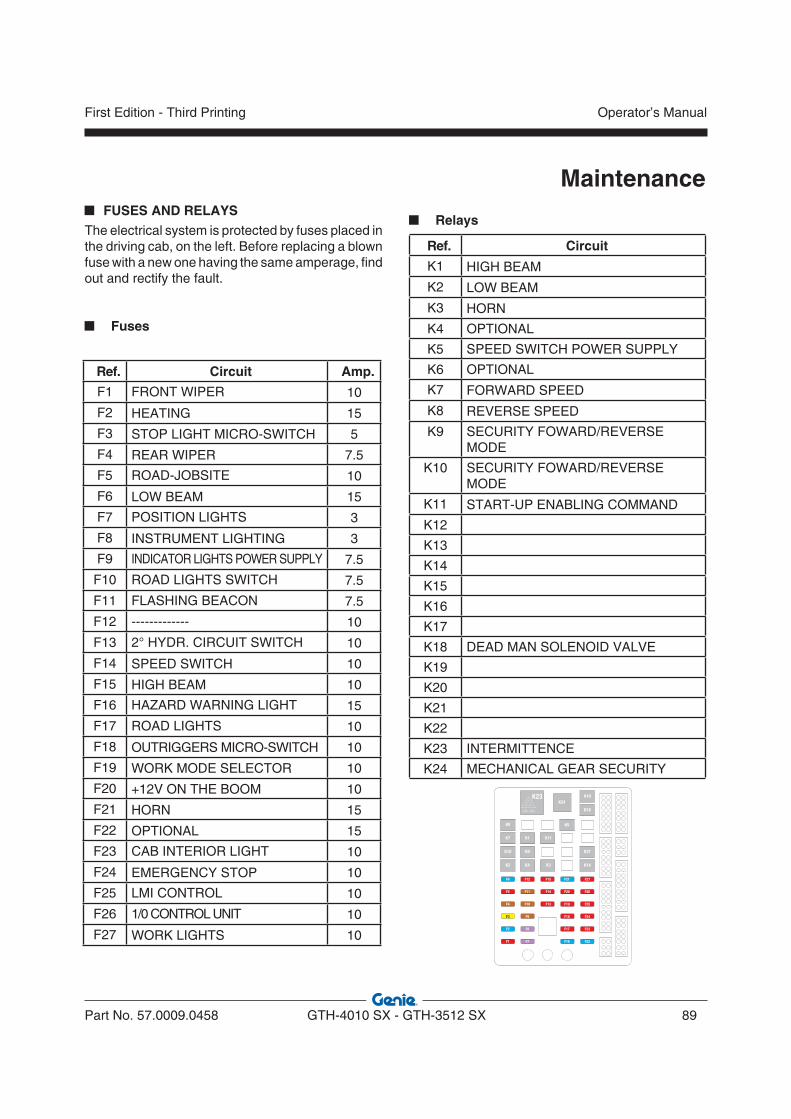
Maintenance FUSES AND RELAYS
The electrical system is protected by fuses placed in the driving cab, on the left. Before replacing a blown fuse with a new one having the same amperage, find out and rectify the fault.
Fuses
K1
K9
K4
K11
K3
K21
K14
K18
F22
F23
F24
F25
F26
F27
F16
F17
F18
F19
F20
F21
F13
F14
F15
F7
F8
F9
F10
F11
F12
F1
F2
F3
F4
F5
F6
K19K23
J3 J2 J1
K8
K7
K10
K2
K24
K5
Ref. Circuit Amp.
F1 FRONT WIPER 10
F2 HEATING 15
F3 STOP LIGHT MICRO-SWITCH 5
F4 REAR WIPER 7.5
F5 ROAD-JOBSITE 10
F6 LOW BEAM 15
F7 POSITION LIGHTS 3
F8 INSTRUMENT LIGHTING 3
F9 INDICATOR LIGHTS POWER SUPPLY 7.5
F10 ROAD LIGHTS SWITCH 7.5
F11 FLASHING BEACON 7.5
F12 ------------- 10
F13 2° HYDR. CIRCUIT SWITCH 10
F14 SPEED SWITCH 10
F15 HIGH BEAM 10
F16 HAZARD WARNING LIGHT 15
F17 ROAD LIGHTS 10
F18 OUTRIGGERS MICRO-SWITCH 10
F19 WORK MODE SELECTOR 10
F20 +12V ON THE BOOM 10
F21 HORN 15
F22 OPTIONAL 15
F23 CAB INTERIOR LIGHT 10
F24 EMERGENCY STOP 10
F25 LMI CONTROL 10
F26 1/0 CONTROL UNIT 10
F27 WORK LIGHTS 10
Relays
Ref. Circuit
K1 HIGH BEAM
K2 LOW BEAM
K3 HORN
K4 OPTIONAL
K5 SPEED SWITCH POWER SUPPLY
K6 OPTIONAL
K7 FORWARD SPEED
K8 REVERSE SPEED
K9 SECURITY FOWARD/REVERSE MODE
K10 SECURITY FOWARD/REVERSE MODE
K11 START-UP ENABLING COMMAND
K12
K13
K14
K15
K16
K17
K18 DEAD MAN SOLENOID VALVE
K19
K20
K21
K22
K23 INTERMITTENCE
K24 MECHANICAL GEAR SECURITY
Part No. 57.0009.0458 GTH-4010 SX - GTH-3512 SX 89
Operator’s ManualFirst Edition - Third Printing
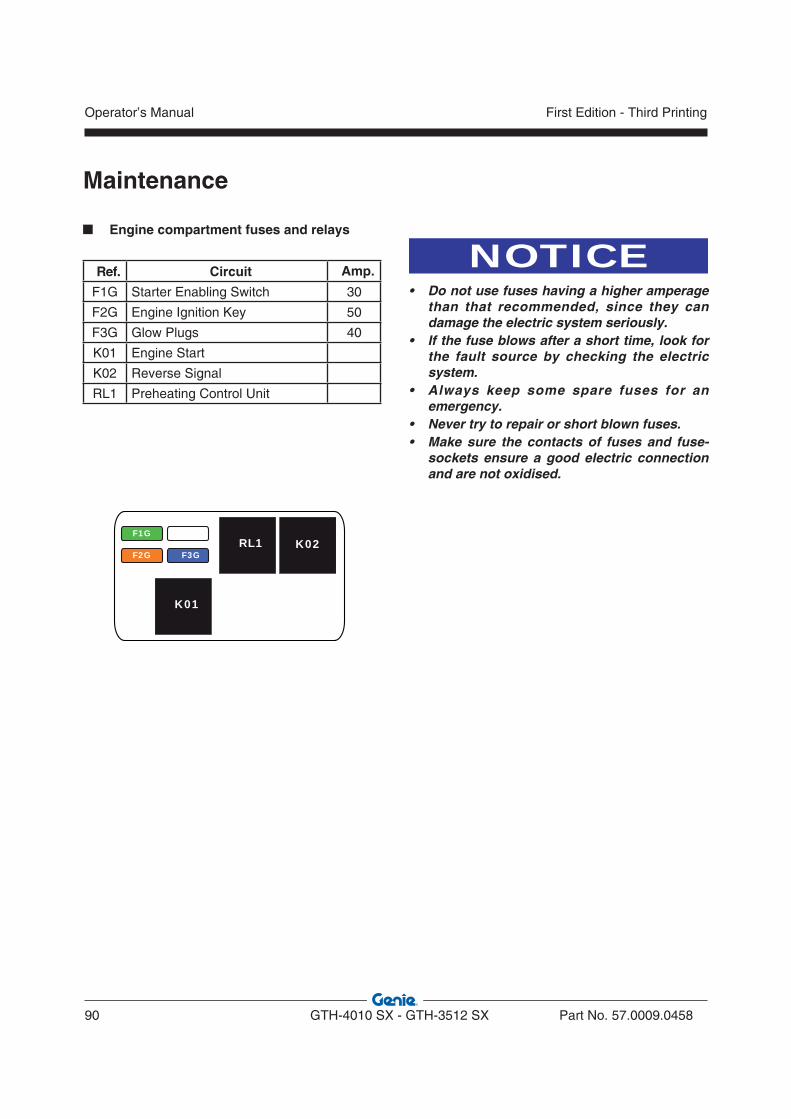
Maintenance
NOTICE• Do not use fuses having a higher amperage
than that recommended, since they can damage the electric system seriously.
• If the fuse blows after a short time, look for the fault source by checking the electric system.
• Always keep some spare fuses for an emergency.
• Never try to repair or short blown fuses.• Make sure the contacts of fuses and fuse-
sockets ensure a good electric connection and are not oxidised.
Engine compartment fuses and relays
Ref. Circuit Amp.
F1G Starter Enabling Switch 30
F2G Engine Ignition Key 50
F3G Glow Plugs 40
K01 Engine Start
K02 Reverse Signal
RL1 Preheating Control Unit
F1G F4GRL1 K02
F2G F3G
K01F5G
Operator’s Manual
90 GTH-4010 SX - GTH-3512 SX Part No. 57.0009.0458
First Edition - Third Printing
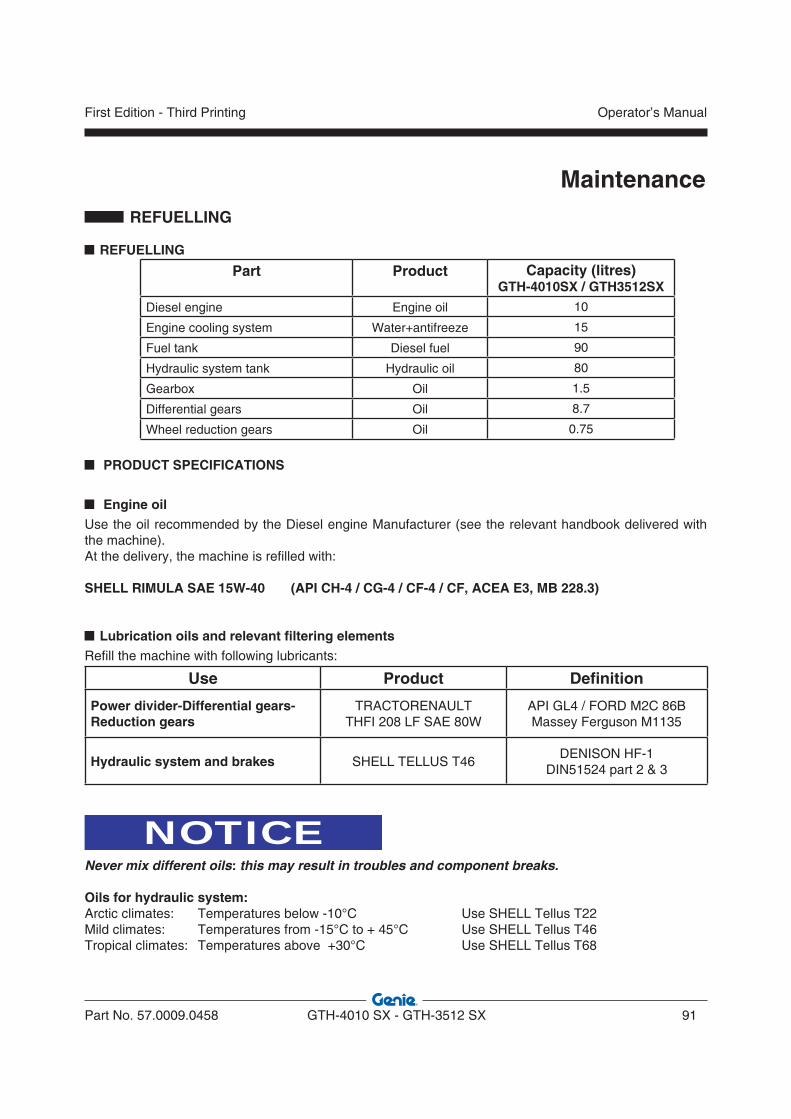
Maintenance REFUELLING
REFUELLING
PRODUCT SPECIFICATIONS
Engine oil Use the oil recommended by the Diesel engine Manufacturer (see the relevant handbook delivered with the machine).At the delivery, the machine is refilled with:
SHELL RIMULA SAE 15W-40 (API CH-4 / CG-4 / CF-4 / CF, ACEA E3, MB 228.3)
Lubrication oils and relevant filtering elementsRefill the machine with following lubricants:
Use Product Definition
Power divider-Differential gears-Reduction gears
TRACTORENAULTTHFI 208 LF SAE 80W
API GL4 / FORD M2C 86BMassey Ferguson M1135
Hydraulic system and brakes SHELL TELLUS T46DENISON HF-1
DIN51524 part 2 & 3
NOTICENever mix different oils: this may result in troubles and component breaks.
Oils for hydraulic system:Arctic climates: Temperatures below -10°C Use SHELL Tellus T22Mild climates: Temperatures from -15°C to + 45°C Use SHELL Tellus T46Tropical climates: Temperatures above +30°C Use SHELL Tellus T68
Part Product Capacity (litres)GTH-4010SX / GTH3512SX
Diesel engine Engine oil 10
Engine cooling system Water+antifreeze 15
Fuel tank Diesel fuel 90
Hydraulic system tank Hydraulic oil 80
Gearbox Oil 1.5
Differential gears Oil 8.7
Wheel reduction gears Oil 0.75
Part No. 57.0009.0458 GTH-4010 SX - GTH-3512 SX 91
Operator’s ManualFirst Edition - Third Printing
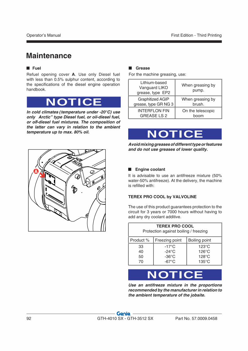
Maintenance
FuelRefuel opening cover A. Use only Diesel fuel with less than 0.5% sulphur content, according to the specifications of the diesel engine operation handbook.
NOTICEIn cold climates (temperature under -20°C) use only “Arctic” type Diesel fuel, or oil-diesel fuel, or oil-diesel fuel mixtures. The composition of the latter can vary in relation to the ambient temperature up to max. 80% oil.
�
GreaseFor the machine greasing, use:
NOTICEAvoid mixing greases of different type or features and do not use greases of lower quality.
Engine coolantIt is advisable to use an antifreeze mixture (50% water-50% antifreeze). At the delivery, the machine is refilled with:
TEREX PRO COOL by VALVOLINE
The use of this product guarantees protection to the circuit for 3 years or 7000 hours without having to add any dry coolant additive.
NOTICEUse an antifreeze mixture in the proportions recommended by the manufacturer in relation to the ambient temperature of the jobsite.
Lithium-based Vanguard LIKO
grease, type EP2
When greasing by pump.
Graphitized AGIP grease, type GR NG 3
When greasing by brush.
INTERFLON FIN GREASE LS 2
On the telescopic boom
TEREX PRO COOLProtection against boiling / freezing
Product % Freezing point Boiling point
33405070
-17°C-24°C-36°C-67°C
123°C126°C128°C135°C
Operator’s Manual
92 GTH-4010 SX - GTH-3512 SX Part No. 57.0009.0458
First Edition - Third Printing

Part No. 57.0009.0458 GTH-4010 SX - GTH-3512 SX 93
Operator’s ManualFirst Edition - Third Printing
Faults and Troubleshooting
This chapter represents a practical guide for the operator for fixing the most common failures and, at the same time, detecting those interventions that must be carried out by qualified technical engineers.If you are unsure about anything, do not carry out operations on the machine, but call in a skilled technician.
WARNINGAny repair work, maintenance or troubleshooting must be carried out with machine stopped, boom in rest position or laid on the ground, parking brake engaged and ignition key removed.
FAULTS AND TROUBLESHOOTING
PROBLEM CAUSES SOLUTIONS
THE DASHBOARD DOES NOT TURN ON
• Battery down • Fuse in the engine
compartment box blown
• Check the battery condition• Check the main fuse in the engine
compartment and replace if necessary
THE STARTER DOES NOT RUN
• Forward/reverse gear selector not in neutral position
• Battery down
• Set the switch to 0
• Recharge or replace the battery
THE STARTER RUNS, BUT THE ENGINE DOES NOT START
• No fuel• Fuel filter clogged
• Fuel hose empty (fuel used up)
• Refuel• Change the filter. See engine
operator handbook)• Refuel, then refer to engine
operator handbook
THE MACHINE DOES NOT MOVE FORWARD/BACK
• Changeover switch in neutral
• Parking brake engaged• Fuse F14 blown
• Set the gear switch to correct position
• Disengage• Check the fuse and replace if
necessary.
NO SELECTION OF THE STEERING MODE
• Fuse F5 blown • Check the fuse and replace if necessary.
THE DLE LOAD LIMITING SYSTEM IS IN ALARM
• Fuse F25 blown
• System failure
• Check and replace fuse, if necessary• Check the load cell functionality
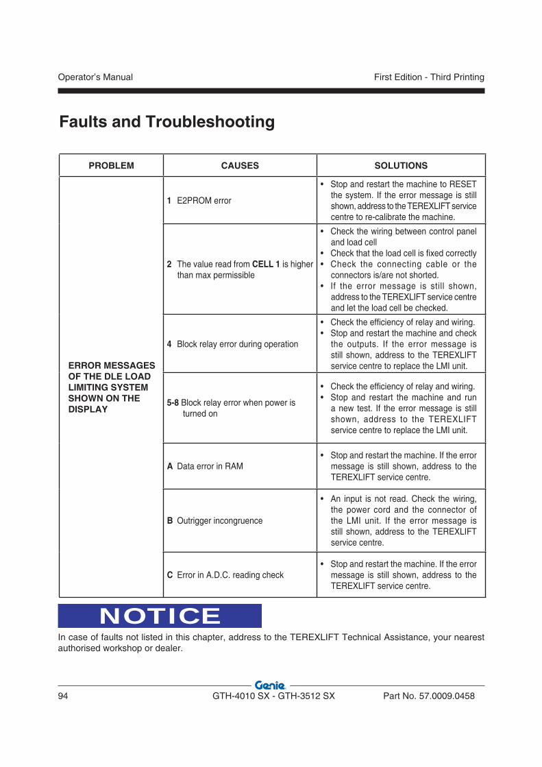
Operator’s Manual
94 GTH-4010 SX - GTH-3512 SX Part No. 57.0009.0458
First Edition - Third Printing
PROBLEM CAUSES SOLUTIONS
ERROR MESSAGES OF THE DLE LOAD LIMITING SYSTEM SHOWN ON THE DISPLAY
1 E2PROM error
• Stop and restart the machine to RESET the system. If the error message is still shown, address to the TEREXLIFT service centre to re-calibrate the machine.
2 The value read from CELL 1 is higher than max permissible
• Check the wiring between control panel and load cell
• Check that the load cell is fixed correctly• Check the connecting cable or the
connectors is/are not shorted.• If the error message is still shown,
address to the TEREXLIFT service centre and let the load cell be checked.
4 Block relay error during operation
• Check the efficiency of relay and wiring.• Stop and restart the machine and check
the outputs. If the error message is still shown, address to the TEREXLIFT service centre to replace the LMI unit.
5-8 Block relay error when power is turned on
• Check the efficiency of relay and wiring.• Stop and restart the machine and run
a new test. If the error message is still shown, address to the TEREXLIFT service centre to replace the LMI unit.
A Data error in RAM• Stop and restart the machine. If the error
message is still shown, address to the TEREXLIFT service centre.
B Outrigger incongruence
• An input is not read. Check the wiring, the power cord and the connector of the LMI unit. If the error message is still shown, address to the TEREXLIFT service centre.
C Error in A.D.C. reading check• Stop and restart the machine. If the error
message is still shown, address to the TEREXLIFT service centre.
Faults and Troubleshooting
NOTICEIn case of faults not listed in this chapter, address to the TEREXLIFT Technical Assistance, your nearest authorised workshop or dealer.
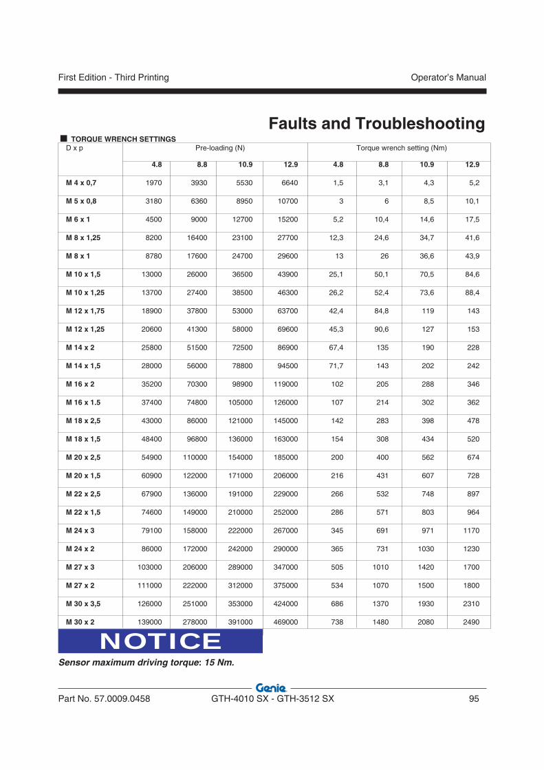
Part No. 57.0009.0458 GTH-4010 SX - GTH-3512 SX 95
Operator’s ManualFirst Edition - Third Printing
Faults and Troubleshooting D x p Pre-loading (N) Torque wrench setting (Nm)
4.8 8.8 10.9 12.9 4.8 8.8 10.9 12.9
M 4 x 0,7 1970 3930 5530 6640 1,5 3,1 4,3 5,2
M 5 x 0,8 3180 6360 8950 10700 3 6 8,5 10,1
M 6 x 1 4500 9000 12700 15200 5,2 10,4 14,6 17,5
M 8 x 1,25 8200 16400 23100 27700 12,3 24,6 34,7 41,6
M 8 x 1 8780 17600 24700 29600 13 26 36,6 43,9
M 10 x 1,5 13000 26000 36500 43900 25,1 50,1 70,5 84,6
M 10 x 1,25 13700 27400 38500 46300 26,2 52,4 73,6 88,4
M 12 x 1,75 18900 37800 53000 63700 42,4 84,8 119 143
M 12 x 1,25 20600 41300 58000 69600 45,3 90,6 127 153
M 14 x 2 25800 51500 72500 86900 67,4 135 190 228
M 14 x 1,5 28000 56000 78800 94500 71,7 143 202 242
M 16 x 2 35200 70300 98900 119000 102 205 288 346
M 16 x 1.5 37400 74800 105000 126000 107 214 302 362
M 18 x 2,5 43000 86000 121000 145000 142 283 398 478
M 18 x 1,5 48400 96800 136000 163000 154 308 434 520
M 20 x 2,5 54900 110000 154000 185000 200 400 562 674
M 20 x 1,5 60900 122000 171000 206000 216 431 607 728
M 22 x 2,5 67900 136000 191000 229000 266 532 748 897
M 22 x 1,5 74600 149000 210000 252000 286 571 803 964
M 24 x 3 79100 158000 222000 267000 345 691 971 1170
M 24 x 2 86000 172000 242000 290000 365 731 1030 1230
M 27 x 3 103000 206000 289000 347000 505 1010 1420 1700
M 27 x 2 111000 222000 312000 375000 534 1070 1500 1800
M 30 x 3,5 126000 251000 353000 424000 686 1370 1930 2310
M 30 x 2 139000 278000 391000 469000 738 1480 2080 2490
NOTICESensor maximum driving torque: 15 Nm.
TORQUE WRENCH SETTINGS

Intentionally blank page
Operator’s Manual
96 GTH-4010 SX - GTH-3512 SX Part No. 57.0009.0458
First Edition - Third Printing
Optional Attachments INTRODUCTION
This section provides information on the optional interchangeable attachments, especially manufac-tured for the handlers.Use only genuine attachments, described in this section, after having read their features thoroughly and understood their use.To install and remove the attachments, follow the instructions supplied in the “Operating Instructions” section.
DANGERWhen replacing interchangeable attachments, keep any person clear of the working area.
DANGERMounting optional attachments, and especially the extension jib, can change the centre of gravity of the machine. Before handling a load, check its weight and compare it with the values on the load charts. The weight of the used attachment must always be deducted from the rated payload.
Part No. 57.0009.0458 GTH-4010 SX - GTH-3512 SX 97
Operator’s ManualFirst Edition - Third Printing

Optional Attachments 800 LITRES SHOVEL
(code 59.0202.0000)
TECHNICAL DATA
Capacity 800 litres
Width 2340 mm
Length 1000 mm
Height 850 mm
Weight 440 kg
CAUTIONAttachment suitable for moving loose material. Do not use for digging operations.
ApplicationQuick coupling attachment for moving soil, sand, debris, cereals, etc.
SafetyStrictly obey the general safety precautions given in section “Safety”.
OperationTo load/unload the material, operate the rotation lever of the attachment holding plate.
CAUTIONWhen using a shovel, load the material only when the boom is completely retracted and push against the heap with straight wheels.
MaintenanceVisually check the shovel for damage before using it.
Operator’s Manual
98 GTH-4010 SX - GTH-3512 SX Part No. 57.0009.0458
First Edition - Third Printing

Optional Attachments
Part No. 57.0009.0458 GTH-4010 SX - GTH-3512 SX 99
Operator’s ManualFirst Edition - Third Printing
2000 LITRES CEREAL SHOVEL
(code 59.0202.1000)
TECHNICAL DATA
Capacity 2000 litres
Width 2270 mm
Length 1600 mm
Height 1350 mm
Weight 550 kg
NOTICEAttachment suitable for moving loose material. Do not use for digging operations.
ApplicationQuick coupling attachment for loading cereals or inert materials, etc.
SafetyStrictly obey the general safety precautions given in section “Safety”.
OperationTo load/unload the material, operate the rotation lever of the attachment holding plate.
CAUTIONWhen using a shovel, load the material only when the boom is completely retracted and push against the heap with straight wheels.
MaintenanceVisually check the shovel for damage before using it.
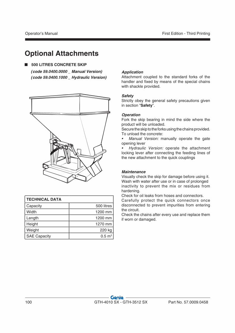
Optional Attachments 500 LITRES CONCRETE SKIP
(code 59.0400.0000 _ Manual Version) (code 59.0400.1000 _ Hydraulic Version)
TECHNICAL DATA
Capacity 500 litres
Width 1200 mm
Length 1200 mm
Height 1270 mm
Weight 220 kg
SAE Capacity 0.5 m3
ApplicationAttachment coupled to the standard forks of the handler and fixed by means of the special chains with shackle provided.
SafetyStrictly obey the general safety precautions given in section “Safety”.
OperationFork the skip bearing in mind the side where the product will be unloaded.Secure the skip to the forks using the chains provided. To unload the concrete:• Manual Version: manually operate the gate opening lever• Hydraulic Version: operate the attachment locking lever after connecting the feeding lines of the new attachment to the quick couplings
MaintenanceVisually check the skip for damage before using it.Wash with water after use or in case of prolongedinactivity to prevent the mix or residues from hardening.Check for oil leaks from hoses and connectors.Carefully protect the quick connectors once disconnected to prevent impurities from entering the circuit.Check the chains after every use and replace them if worn or damaged.
Operator’s Manual
100 GTH-4010 SX - GTH-3512 SX Part No. 57.0009.0458
First Edition - Third Printing

Optional Attachments
800 LITRES CONCRETE SKIP
(code 59.0400.2000 _ Manual Version) (code 59.0400.3000 _ Hydraulic Version)
TECHNICAL DATA
Capacity 800 litres
Width 1200 mm
Length 1200 mm
Height 1520 mm
Weight 260 kg
SAE Capacity 0.8 m3
ApplicationAttachment coupled to the standard forks of the handler and fixed by means of the special chains with shackle provided.
SafetyStrictly obey the general safety precautions given in section “Safety”.
OperationFork the skip bearing in mind the side where the product will be unloaded.Secure the skip to the forks using the chains provided. To unload the concrete:• Manual Version: manually operate the gate opening lever• Hydraulic Version: operate the attachment locking lever after connecting the feeding lines of the new attachment to the quick couplings
MaintenanceVisually check the skip for damage before using it.Wash with water after use or in case of prolongedinactivity to prevent the mix or residues from hardening.Check for oil leaks from hoses and connectors.Carefully protect the quick connectors once disconnected to prevent impurities from entering the circuit.Check the chains after every use and replace them if worn or damaged.
Part No. 57.0009.0458 GTH-4010 SX - GTH-3512 SX 101
Operator’s ManualFirst Edition - Third Printing

Optional Attachments 500 LT MIXING BUCKET
(code 59.0401.0000)
TECHNICAL DATA
Width (A) 1850 mm
Length (B) 1080 mm
Height (C) 1120 mm
Empty Weight 780 kg
All Up Weight 2000 kg
Output Capacity 500 lt
Total capacity 785 lt
Output level from shaft centre (D) 140 mm
ApplicationQuick coupling attachment for mixing and distributing concrete.
SafetyStrictly obey the general safety precautions given in section “Safety”.
OperationTo load/unload the material, operate the rotation lever of the attachment holding plate.To enable the mixer movement, press switch 33, located on the left side of the driving seat base. For further information, see paragraph “Auxiliary drive controls” in the section “Controls And In-struments”
MaintenanceVisually check the bucket for damage before using it. Wash thoroughly with water after use or in case of prolonged inactivity to prevent the mix or residues from hardening.Check for oil leaks from hoses and connectors.Carefully protect the quick connectors once disconnected to prevent impurities from entering the circuit.
WARNINGBefore any maintenance, rest the bucket on the ground, stop the machine, remove the starter key and lock the cab door to prevent anybody from gaining access to the control panel.
A
C
B
D
REST POSITION
Operator’s Manual
102 GTH-4010 SX - GTH-3512 SX Part No. 57.0009.0458
First Edition - Third Printing

Optional Attachments FORKS WITH HYDRAULIC SIDE-SHIFT
(code 59.0601.2000)
TECHNICAL DATA
Payload 4000 kg
Width 1400 mm
Length 1600 mm
Height (with protection) 1140 mm
Weight 180 kg
Stroke ± 100
Fork Attachments FEM 3
ApplicationQuick-coupling fitted attachment for handling palletised loads with possibility of shifting the load to the side by ± 100 mm. SafetyStrictly obey the general safety precautions given in section “Safety”.• Do not load loose materials• Do not move superposed pallets
OperationTo adjust the tilting, operate the rotation lever of the attachment holding plate.To side-shift, operate the attachment locking lever after connecting the feeding lines of the new attachment to the quick couplings (see page F-2).
MaintenanceVisually check the attachment for damage before using it. Check for hydraulic oil leaks. Daily grease the joints using a greasing gun, and smear the sliding guides with graphitized grease.
Part No. 57.0009.0458 GTH-4010 SX - GTH-3512 SX 103
Operator’s ManualFirst Edition - Third Printing

Optional Attachments 900 KG EXTENSION JIB
(code 59.0802.0000 _ Mechanical Version) (code 59.0801.9000 _ Hydraulic Version)
TECHNICAL DATA
Payload 900 kg
Width 990 mm
Length 4125 mm
Height 600 mm
Weight 262 kg
ApplicationQuick-coupling fitted attachment for maintenance interventions at high working heights.
SafetyStrictly obey the general safety precautions given in section “Safety”.Never lift wrongly slung loads. Avoid abrupt acceleration or deceleration.Avoid load oscillations, and especially do not move the load from the vertical pull line. Do not pull crosswise and do not tow.
OperationTo change the working height, operate the rotation lever of the attachment holding plate.
MaintenanceVisually check the jib for damage before using it. Check the safety catch is in good working order.Daily grease the joints using the greasing gun.
Make sure this attachment can be used in the destination country of the machine. Application must be submitted directly by the user.
Operator’s Manual
104 GTH-4010 SX - GTH-3512 SX Part No. 57.0009.0458
First Edition - Third Printing
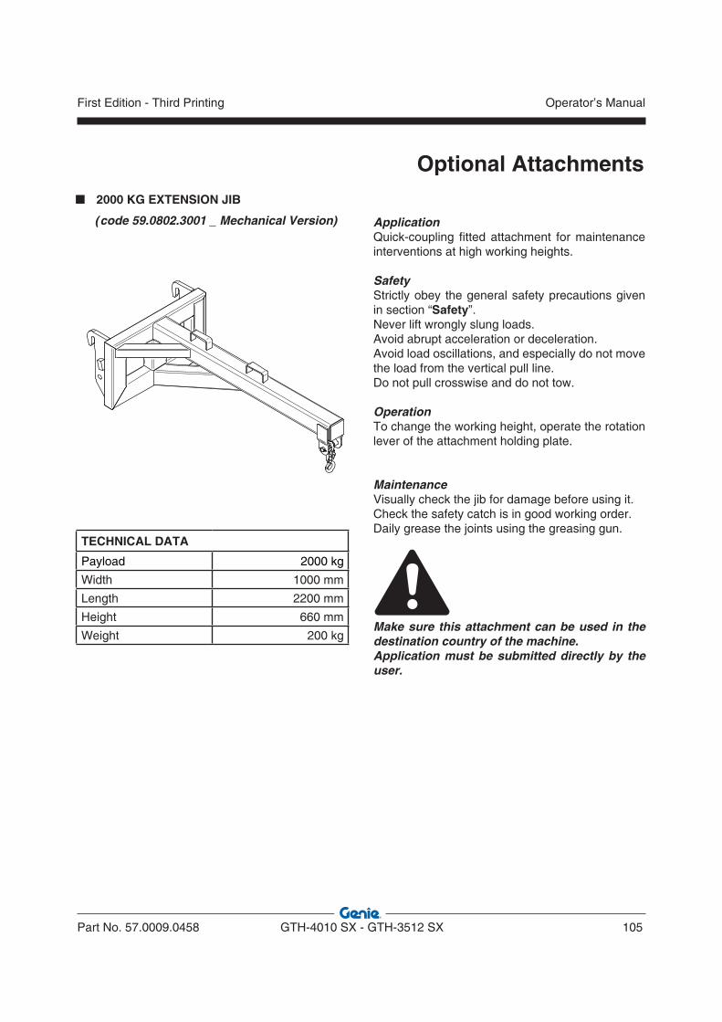
Optional Attachments 2000 KG EXTENSION JIB
(code 59.0802.3001 _ Mechanical Version)
TECHNICAL DATA
Payload 2000 kg
Width 1000 mm
Length 2200 mm
Height 660 mm
Weight 200 kg
ApplicationQuick-coupling fitted attachment for maintenance interventions at high working heights.
SafetyStrictly obey the general safety precautions given in section “Safety”.Never lift wrongly slung loads. Avoid abrupt acceleration or deceleration.Avoid load oscillations, and especially do not move the load from the vertical pull line. Do not pull crosswise and do not tow.
OperationTo change the working height, operate the rotation lever of the attachment holding plate.
MaintenanceVisually check the jib for damage before using it. Check the safety catch is in good working order.Daily grease the joints using the greasing gun.
Make sure this attachment can be used in the destination country of the machine. Application must be submitted directly by the user.
Part No. 57.0009.0458 GTH-4010 SX - GTH-3512 SX 105
Operator’s ManualFirst Edition - Third Printing
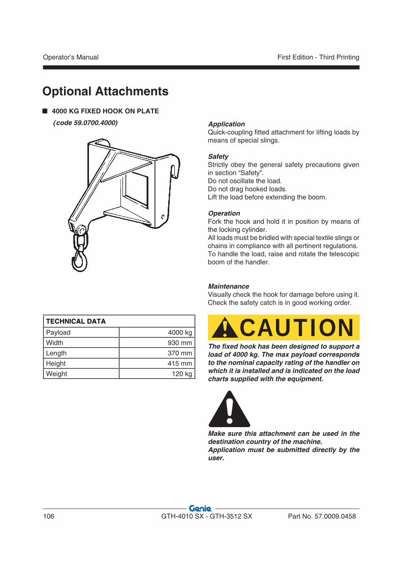
Optional Attachments 4000 KG FIXED HOOK ON PLATE
(code 59.0700.4000)
TECHNICAL DATA
Payload 4000 kg
Width 930 mm
Length 370 mm
Height 415 mm
Weight 120 kg
Application Quick-coupling fitted attachment for lifting loads by means of special slings.
SafetyStrictly obey the general safety precautions given in section “Safety”.Do not oscillate the load. Do not drag hooked loads. Lift the load before extending the boom.
OperationFork the hook and hold it in position by means of the locking cylinder. All loads must be bridled with special textile slings or chains in compliance with all pertinent regulations.To handle the load, raise and rotate the telescopic boom of the handler.
MaintenanceVisually check the hook for damage before using it. Check the safety catch is in good working order.
CAUTIONThe fixed hook has been designed to support a load of 4000 kg. The max payload corresponds to the nominal capacity rating of the handler on which it is installed and is indicated on the load charts supplied with the equipment.
Make sure this attachment can be used in the destination country of the machine. Application must be submitted directly by the user.
Operator’s Manual
106 GTH-4010 SX - GTH-3512 SX Part No. 57.0009.0458
First Edition - Third Printing
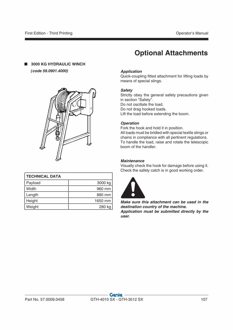
Optional Attachments 3000 KG HYDRAULIC WINCH
(code 59.0901.4000)
TECHNICAL DATA
Payload 3000 kg
Width 960 mm
Length 880 mm
Height 1650 mm
Weight 280 kg
Application Quick-coupling fitted attachment for lifting loads by means of special slings.
SafetyStrictly obey the general safety precautions given in section “Safety”.Do not oscillate the load. Do not drag hooked loads. Lift the load before extending the boom.
OperationFork the hook and hold it in position. All loads must be bridled with special textile slings or chains in compliance with all pertinent regulations.To handle the load, raise and rotate the telescopic boom of the handler.
MaintenanceVisually check the hook for damage before using it. Check the safety catch is in good working order.
Make sure this attachment can be used in the destination country of the machine. Application must be submitted directly by the user.
Part No. 57.0009.0458 GTH-4010 SX - GTH-3512 SX 107
Operator’s ManualFirst Edition - Third Printing

Optional Attachments BASKET FOR BRICKS
(code 59.0400.7000)
TECHNICAL DATA
Width 800 mm
Length 1100mm
Height 1150 mm
ApplicationAttachment used to handle construction manufactured products, to be fixed to the standard forks of the handler and locked in position with the chains with shackles supplied.
SafetyStrictly obey the general safety precautions given in section “Safety”.
OperationFork the basket from the rear side being careful that the door that can be opened is at the front.Secure the basket to the forks using the chains supplied.
MaintenanceVisually check the attachment for damage before using it.
Operator’s Manual
108 GTH-4010 SX - GTH-3512 SX Part No. 57.0009.0458
First Edition - Third Printing

Specifications
GTH 4010 SX GTH 3512 SX
MAIN DIMENSIONS A Overall height ................................................................................ mmB Height to the steering wheel ......................................................... mmC Overall width ................................................................................. mmD Cab width ...................................................................................... mmE Track ............................................................................................. mmF Wheel-base ................................................................................... mmG Length to the front tyres ................................................................ mmH Length to the attachment holding plate ......................................... mmI Ground clearance, center ............................................................... mmJ Max width with extended outriggers .............................................. mmK Ground clearance, axle ................................................................. mm• Internal steering radius ................................................................... mm• External steering radius ................................................................. mm
241016502250
7801850275043906060
4052935
40018003850
241016502250
7801850275043905780
4052935
40018003850
LIMITS OF USEM1 Obstruction angle .............................................................................M2 Departure angle ................................................................................• Min/max ambient temperature ......................................................... °C
32°31°
-20°/+40°
32°37°
-20°/+40°
WEIGHT• Weight in working order ................................................................... kg 9200 8900
SPEED• Max travel speed (max load) ........................................................ km/h• Max travel speed (with fork) ......................................................... km/h
535
535
Part No. 57.0009.0458 GTH-4010 SX - GTH-3512 SX 109
Operator’s ManualFirst Edition - Third Printing
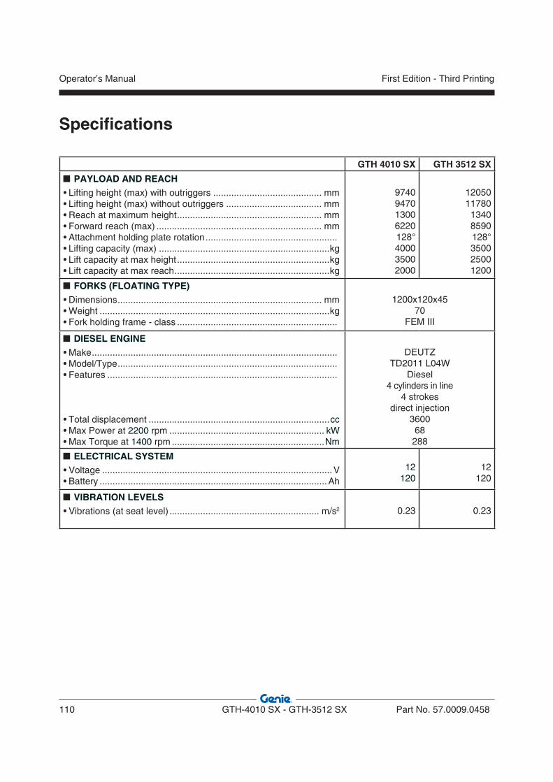
Specifications
GTH 4010 SX GTH 3512 SX
PAYLOAD AND REACH • Lifting height (max) with outriggers .......................................... mm• Lifting height (max) without outriggers ..................................... mm• Reach at maximum height ........................................................ mm• Forward reach (max) ................................................................ mm• Attachment holding plate rotation ...................................................• Lifting capacity (max) ..................................................................kg• Lift capacity at max height ...........................................................kg• Lift capacity at max reach ............................................................kg
9740947013006220128°400035002000
1205011780
13408590128°350025001200
FORKS (FLOATING TYPE)• Dimensions ............................................................................... mm• Weight .........................................................................................kg• Fork holding frame - class ..............................................................
1200x120x4570
FEM III
DIESEL ENGINE• Make ...............................................................................................• Model/Type .....................................................................................• Features .........................................................................................
• Total displacement ......................................................................cc• Max Power at 2200 rpm ............................................................ kW • Max Torque at 1400 rpm ...........................................................Nm
DEUTZTD2011 L04W
Diesel4 cylinders in line
4 strokesdirect injection
360068
288
ELECTRICAL SYSTEM• Voltage .........................................................................................V• Battery ........................................................................................Ah
12120
12120
VIBRATION LEVELS• Vibrations (at seat level) .......................................................... m/s2 0.23 0.23
Operator’s Manual
110 GTH-4010 SX - GTH-3512 SX Part No. 57.0009.0458
First Edition - Third Printing

Part No. 57.0009.0458 GTH-4010 SX - GTH-3512 SX 111
Operator’s ManualFirst Edition - Third Printing
Load Charts
09.4618.1093
GTH-3512 SX
LOAD CHART WITH FORKS GTH 3512 SX ON OUTRIGGERS

Operator’s Manual
112 GTH-4010 SX - GTH-3512 SX Part No. 57.0009.0458
First Edition - Third Printing
09.4618.1094
GTH-3512 SX
LOAD CHART WITH FORKS GTH 3512 SX ON WHEEL
Load Charts

Part No. 57.0009.0458 GTH-4010 SX - GTH-3512 SX 113
Operator’s ManualFirst Edition - Third Printing
09.4618.1095
GTH-3512 SX
LOAD CHART WITH WINCH GTH 3512 SX ON OUTRIGGERS
Load Charts
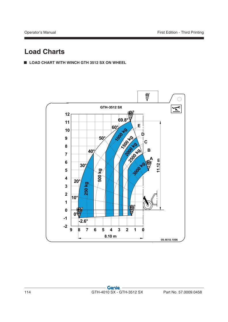
Operator’s Manual
114 GTH-4010 SX - GTH-3512 SX Part No. 57.0009.0458
First Edition - Third Printing
09.4618.1096
GTH-3512 SX
LOAD CHART WITH WINCH GTH 3512 SX ON WHEEL
Load Charts

Part No. 57.0009.0458 GTH-4010 SX - GTH-3512 SX 115
Operator’s ManualFirst Edition - Third Printing
Load Charts
09.4618.1099
GTH-3512 SX
LOAD CHART WITH HOOK GTH 3512 SX ON OUTRIGGERS
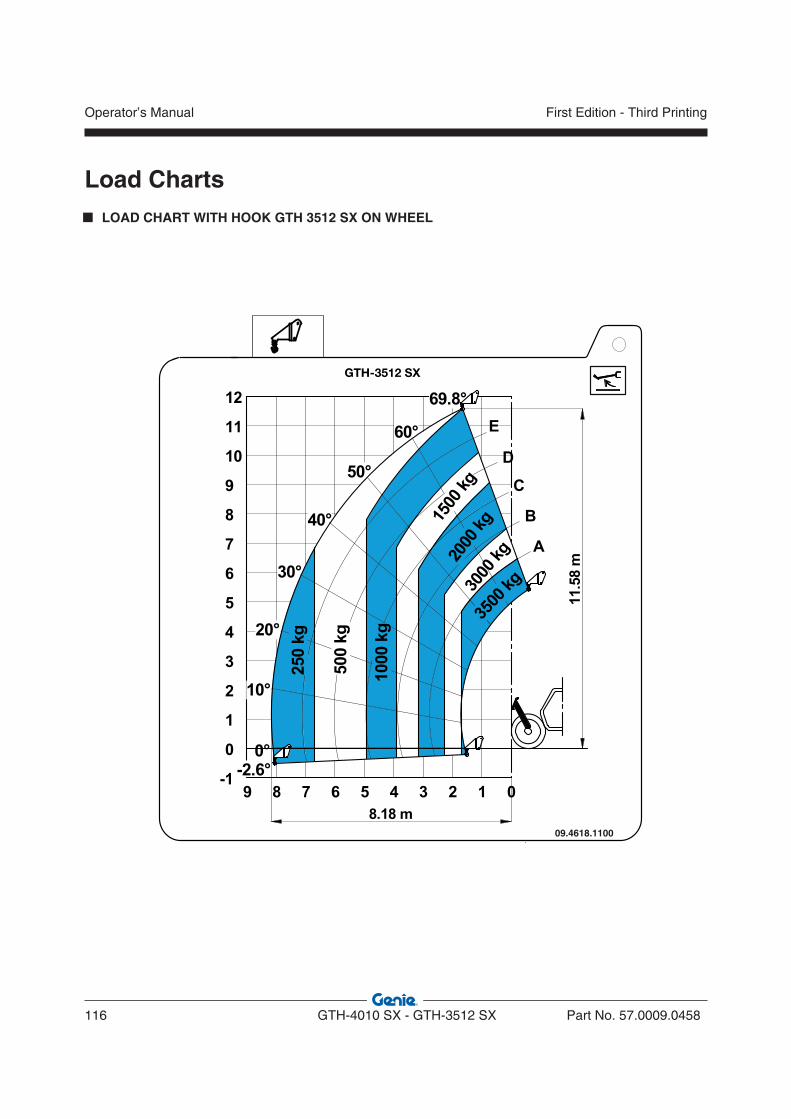
Operator’s Manual
116 GTH-4010 SX - GTH-3512 SX Part No. 57.0009.0458
First Edition - Third Printing
LOAD CHART WITH HOOK GTH 3512 SX ON WHEEL
Load Charts
09.4618.1100
GTH-3512 SX
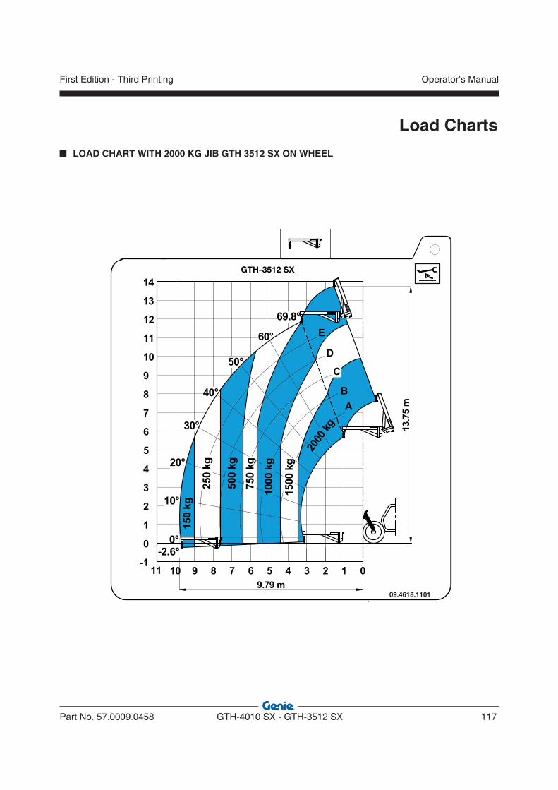
Part No. 57.0009.0458 GTH-4010 SX - GTH-3512 SX 117
Operator’s ManualFirst Edition - Third Printing
Load Charts
09.4618.1101
GTH-3512 SX
LOAD CHART WITH 2000 KG JIB GTH 3512 SX ON WHEEL
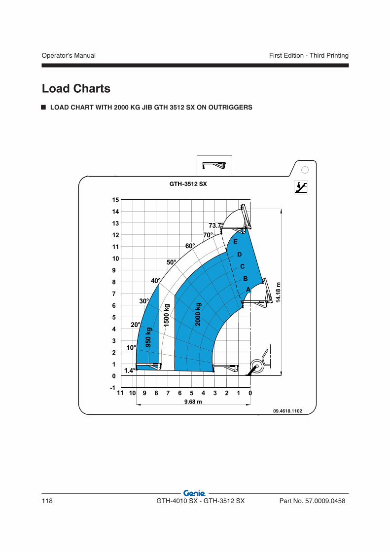
Operator’s Manual
118 GTH-4010 SX - GTH-3512 SX Part No. 57.0009.0458
First Edition - Third Printing
LOAD CHART WITH 2000 KG JIB GTH 3512 SX ON OUTRIGGERS
Load Charts
09.4618.1102
GTH-3512 SX
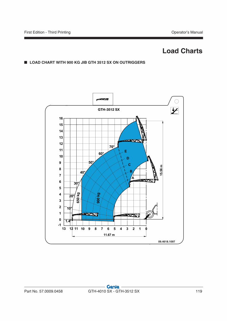
Part No. 57.0009.0458 GTH-4010 SX - GTH-3512 SX 119
Operator’s ManualFirst Edition - Third Printing
Load Charts
09.4618.1097
GTH-3512 SX
LOAD CHART WITH 900 KG JIB GTH 3512 SX ON OUTRIGGERS
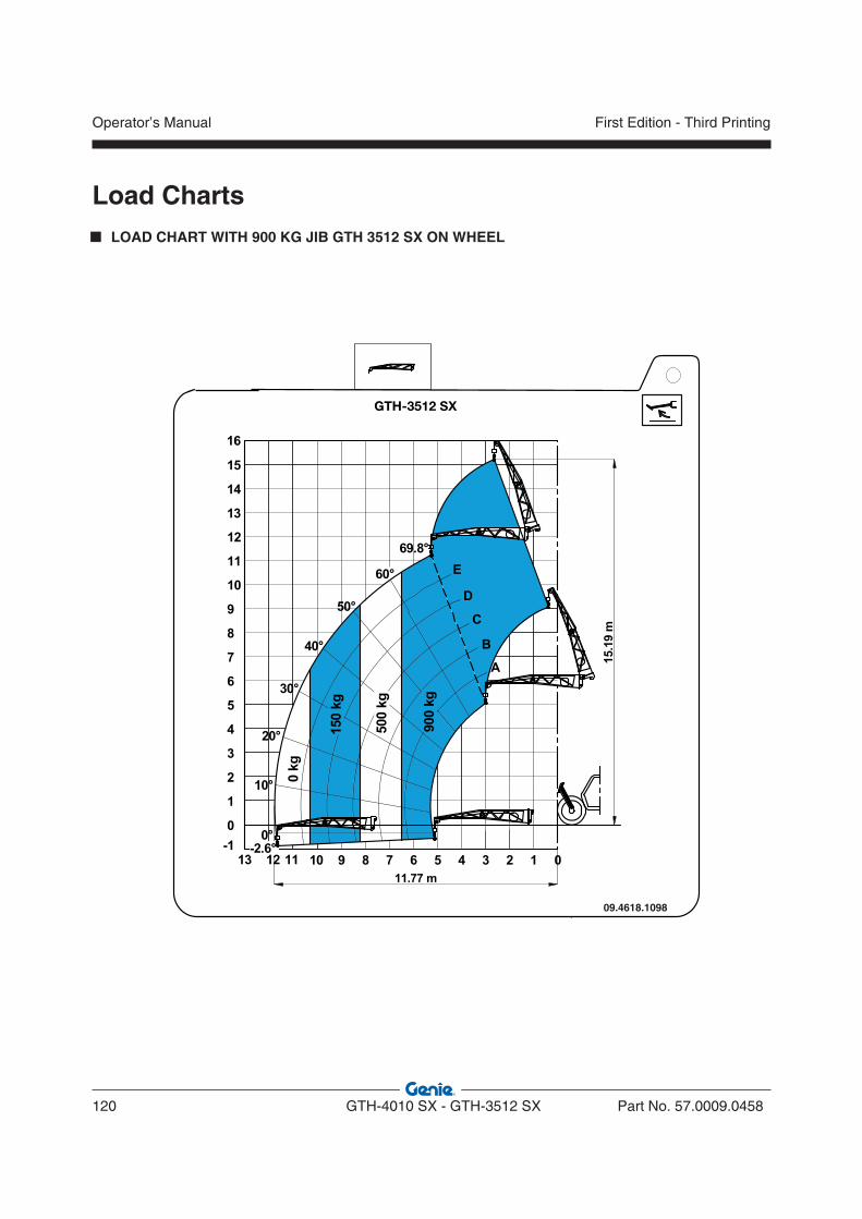
Operator’s Manual
120 GTH-4010 SX - GTH-3512 SX Part No. 57.0009.0458
First Edition - Third Printing
LOAD CHART WITH 900 KG JIB GTH 3512 SX ON WHEEL
Load Charts
09.4618.1098
GTH-3512 SX
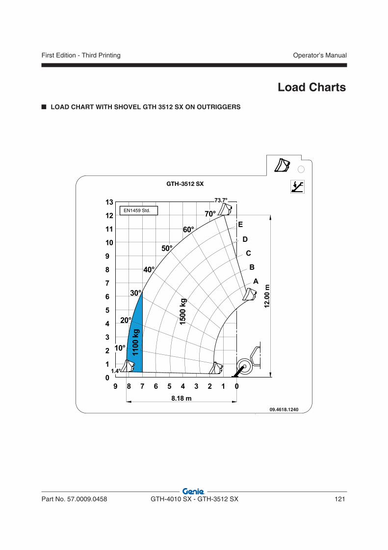
Part No. 57.0009.0458 GTH-4010 SX - GTH-3512 SX 121
Operator’s ManualFirst Edition - Third Printing
Load Charts
LOAD CHART WITH SHOVEL GTH 3512 SX ON OUTRIGGERS
09.4618.1240
GTH-3512 SX
EN1459 Std.
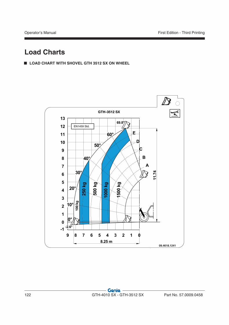
Operator’s Manual
122 GTH-4010 SX - GTH-3512 SX Part No. 57.0009.0458
First Edition - Third Printing
LOAD CHART WITH SHOVEL GTH 3512 SX ON WHEEL
Load Charts
09.4618.1241
GTH-3512 SX
EN1459 Std.
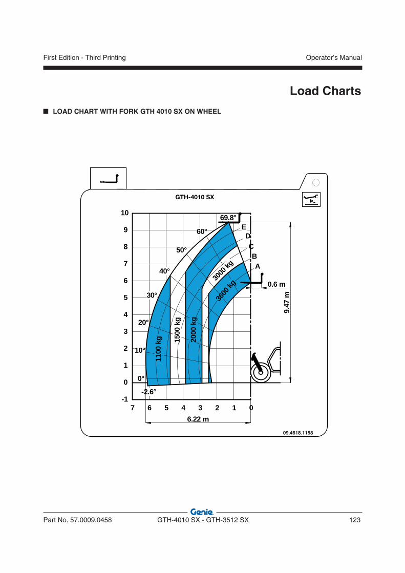
Part No. 57.0009.0458 GTH-4010 SX - GTH-3512 SX 123
Operator’s ManualFirst Edition - Third Printing
Load Charts
LOAD CHART WITH FORK GTH 4010 SX ON WHEEL
09.4618.1158
GTH-4010 SX
3
A
-2.6°
60°
69.8°
0
0°
50°
40°
30°
20°
10°
1234567
4
5
6
7
8
9
10
2
1
0
-1
BC
DE
9.47
m
6.22 m
0.6 m
1500
kg
3000
kg
3600
kg
2000
kg
1100
kg
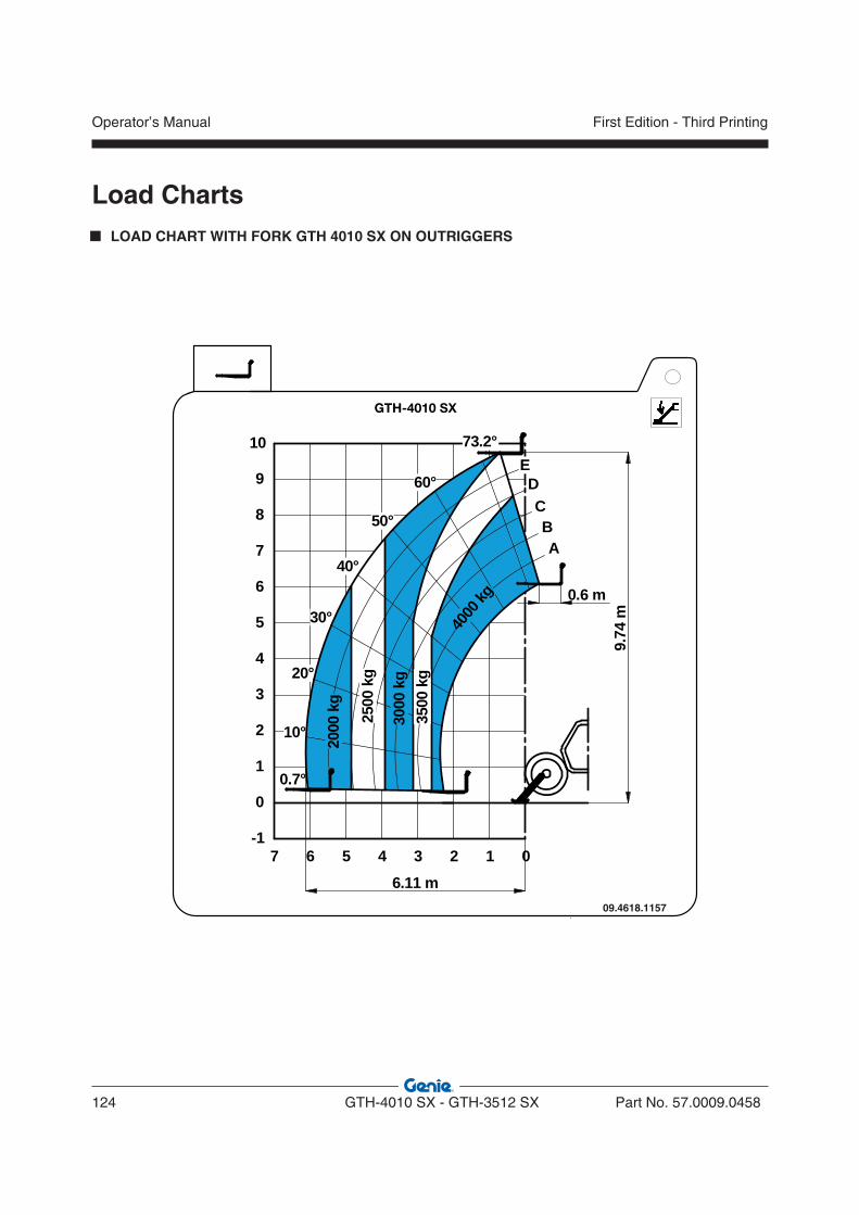
Operator’s Manual
124 GTH-4010 SX - GTH-3512 SX Part No. 57.0009.0458
First Edition - Third Printing
LOAD CHART WITH FORK GTH 4010 SX ON OUTRIGGERS
Load Charts
09.4618.1157
GTH-4010 SX
3
A
60°
73.2°
0
50°
40°
30°
20°
10°
1234567
4
5
6
7
8
9
10
2
1
0
-1
BC
DE
0.7°
9.74
m
6.11 m
0.6 m
3500
kg
2500
kg
4000
kg
3000
kg
2000
kg
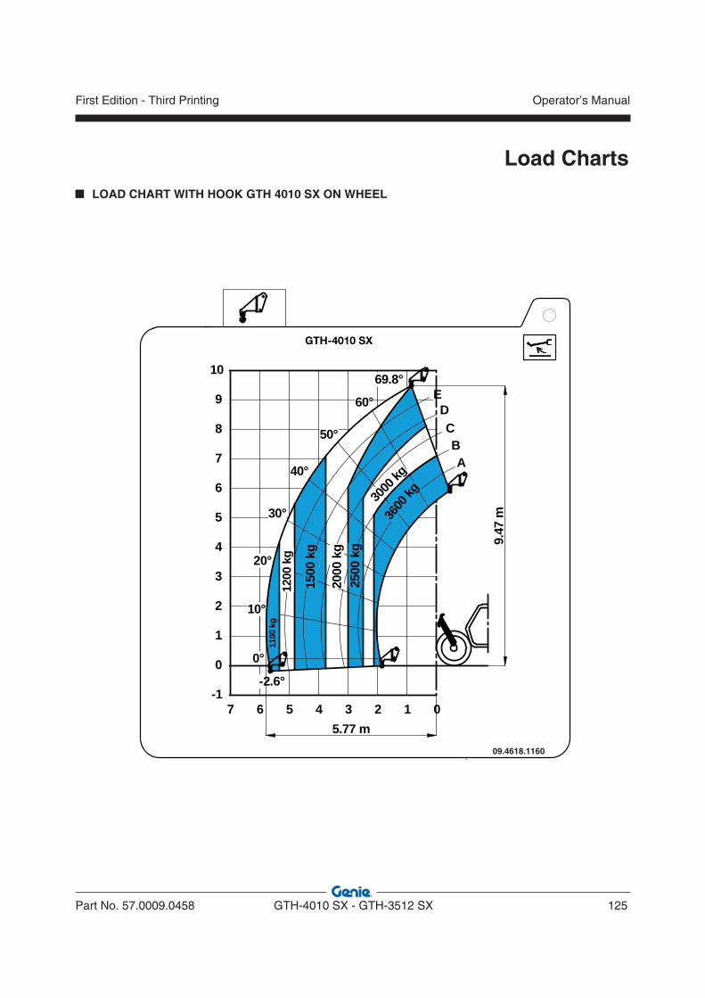
Part No. 57.0009.0458 GTH-4010 SX - GTH-3512 SX 125
Operator’s ManualFirst Edition - Third Printing
Load Charts
LOAD CHART WITH HOOK GTH 4010 SX ON WHEEL
09.4618.1160
GTH-4010 SX
3
A
-2.6°
60°
69.8°
0
0°
50°
40°
30°
20°
10°
1234567
4
5
6
7
8
9
10
2
1
0
-1
BC
DE
9.47
m
5.77 m
1200
kg
3600
kg
2000
kg
2500
kg
1500
kg
1100
kg
3000
kg

Operator’s Manual
126 GTH-4010 SX - GTH-3512 SX Part No. 57.0009.0458
First Edition - Third Printing
LOAD CHART WITH HOOK GTH 4010 SX ON OUTRIGGERS
Load Charts
09.4618.1159
GTH-4010 SX
3
A
60°
73.2°
0
50°
40°
30°
20°
10°
1234567
4
5
6
7
8
9
10
2
1
0
-1
BC
DE
0.7°
9.75
m
5.67 m
70°
3000
kg
2500
kg
3500
kg
4000
kg
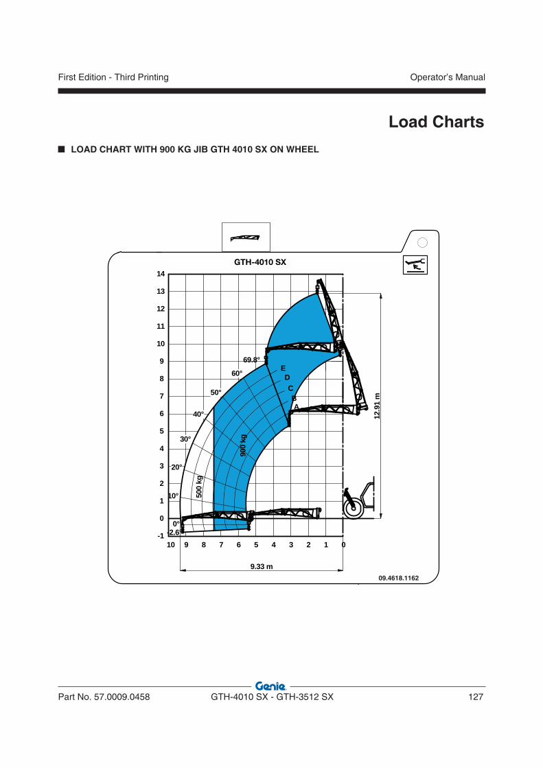
Part No. 57.0009.0458 GTH-4010 SX - GTH-3512 SX 127
Operator’s ManualFirst Edition - Third Printing
Load Charts
LOAD CHART WITH 900 KG JIB GTH 4010 SX ON WHEEL
09.4618.1162
GTH-4010 SX
3
-2.6°
69.8°
0
0°
10°
1234567
4
5
6
7
8
9
10
2
1
0
-1
9.33 m
8910
60°
50°
40°
30°
20°
11
12
13
14
500
kg
AB
CD
E
900
kg
12.9
1 m
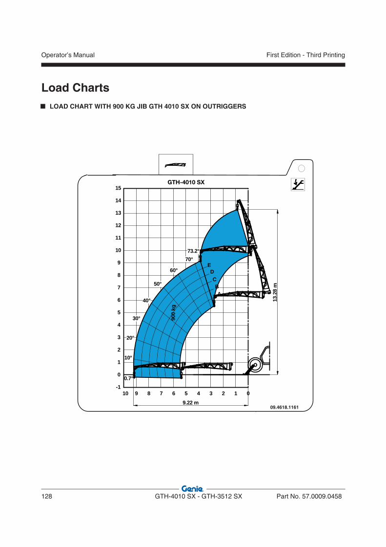
Operator’s Manual
128 GTH-4010 SX - GTH-3512 SX Part No. 57.0009.0458
First Edition - Third Printing
LOAD CHART WITH 900 KG JIB GTH 4010 SX ON OUTRIGGERS
Load Charts
09.4618.1161
GTH-4010 SX
3
A
0
10°
1234567
4
5
6
7
8
9
10
2
1
0
-10.7°
9.22 m
20°
30°
60°
73.2°
50°
40°
70°
8910
11
12
13
14
15
CB
ED
13.2
8 m
900
kg
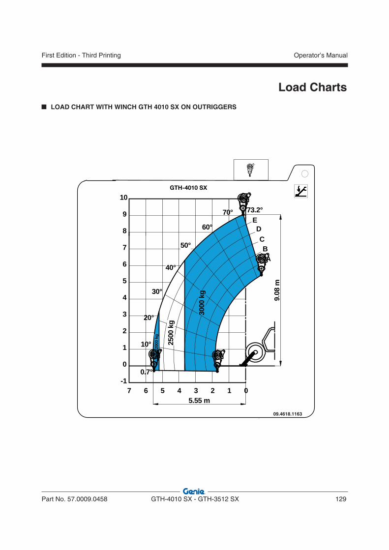
Part No. 57.0009.0458 GTH-4010 SX - GTH-3512 SX 129
Operator’s ManualFirst Edition - Third Printing
Load Charts
LOAD CHART WITH WINCH GTH 4010 SX ON OUTRIGGERS
09.4618.1163
GTH-4010 SX
3
0
10°
123456
4
5
6
7
8
9
10
2
1
0
-1
BC
DE
0.7°
9.08
m
5.55 m
20°
30°
60°
50°
40°
70°
7
73.2°
A
2000
kg
2500
kg
3000
kg
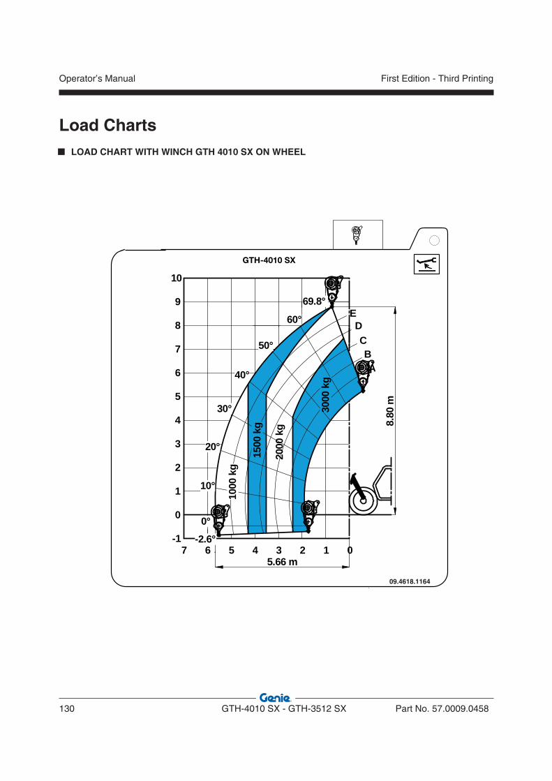
Operator’s Manual
130 GTH-4010 SX - GTH-3512 SX Part No. 57.0009.0458
First Edition - Third Printing
LOAD CHART WITH WINCH GTH 4010 SX ON WHEEL
Load Charts
09.4618.1164
GTH-4010 SX
3
A
01234567
4
5
6
7
8
9
10
2
1
0
-1
BC
DE
5.66 m
2000
kg
3000
kg
1500
kg
1000
kg
-2.6°
60°
69.8°
0°
50°
40°
30°
20°
10°
8.80
m
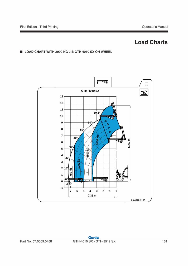
Part No. 57.0009.0458 GTH-4010 SX - GTH-3512 SX 131
Operator’s ManualFirst Edition - Third Printing
Load Charts
LOAD CHART WITH 2000 KG JIB GTH 4010 SX ON WHEEL
09.4618.1166
GTH-4010 SX
3
01234567
4
5
6
7
8
9
10
2
1
0
-1-2.6°
60°
69.8°
50°
40°
30°
20°
10°
11
12
13
1500
kg
750
kg
7.35 m
0°
AB
CD
E
2000
kg
1000
kg
11.6
0 m
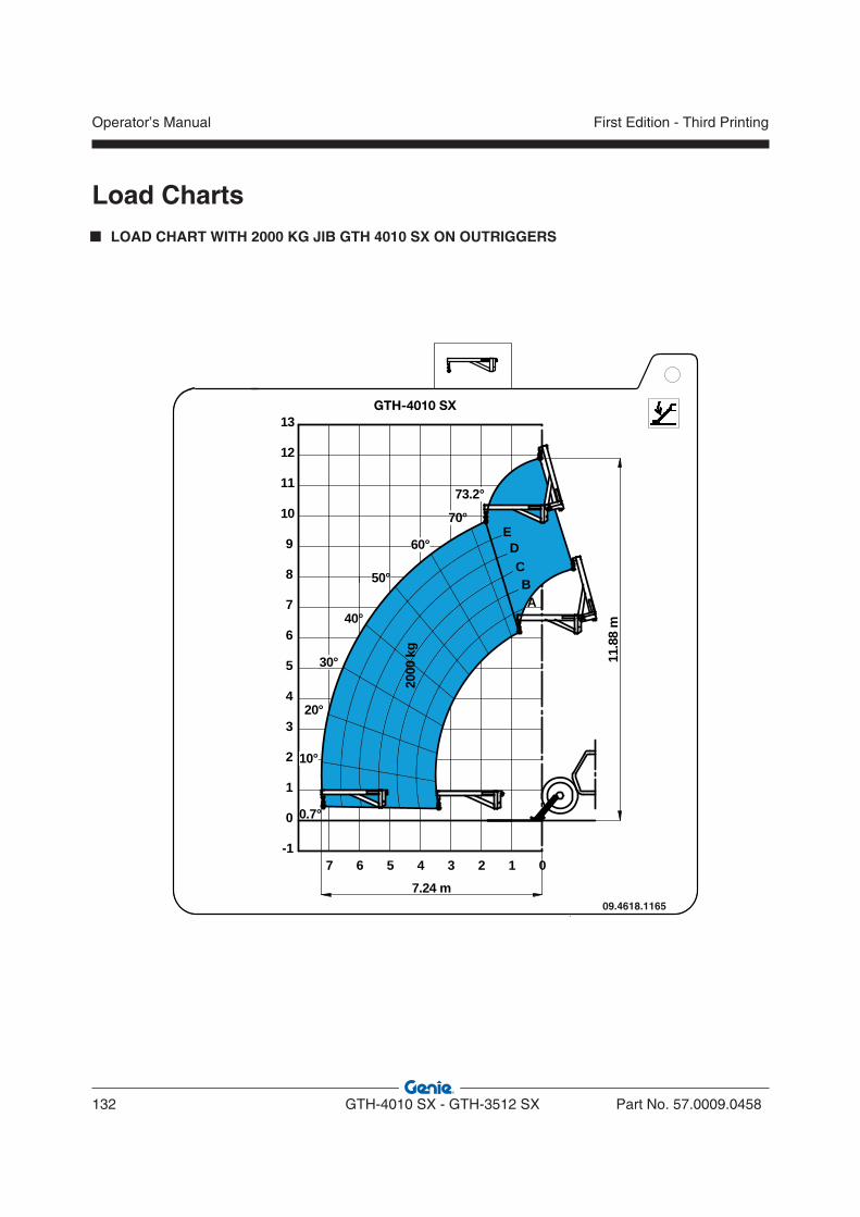
Operator’s Manual
132 GTH-4010 SX - GTH-3512 SX Part No. 57.0009.0458
First Edition - Third Printing
LOAD CHART WITH 2000 KG JIB GTH 4010 SX ON OUTRIGGERS
Load Charts
09.4618.1165
GTH-4010 SX
0.7°
3
A
0123456
4
5
6
7
8
9
10
2
1
0
-1
7.24 m
20°
50°
7
10°
60°
40°
70°
30°
11
12
13
73.2°
BC
DE
2000
kg
11.8
8 m

Part No. 57.0009.0458 GTH-4010 SX - GTH-3512 SX 133
Operator’s ManualFirst Edition - Third Printing
Load Charts
LOAD CHART WITH SHOVEL GTH 4010 SX ON WHEEL
UNDER CONSTRUCTIONUNDER CONSTRUCTION

Operator’s Manual
134 GTH-4010 SX - GTH-3512 SX Part No. 57.0009.0458
First Edition - Third Printing
LOAD CHART WITH SHOVEL GTH 4010 SX ON OUTRIGGERS
Load Charts
UNDER CONSTRUCTIONUNDER CONSTRUCTION
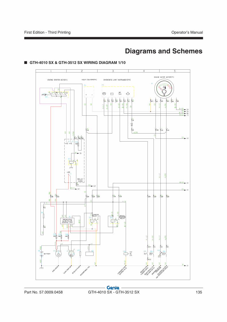
Part No. 57.0009.0458 GTH-4010 SX - GTH-3512 SX 135
Operator’s ManualFirst Edition - Third Printing
Diagrams and Schemes
GTH-4010 SX & GTH-3512 SX WIRING DIAGRAM 1/10

Operator’s Manual
136 GTH-4010 SX - GTH-3512 SX Part No. 57.0009.0458
First Edition - Third Printing
Diagrams and Schemes GTH-4010 SX & GTH-3512 SX WIRING DIAGRAM 2/10
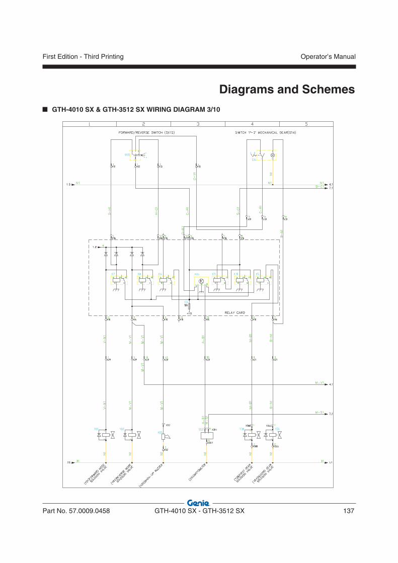
Part No. 57.0009.0458 GTH-4010 SX - GTH-3512 SX 137
Operator’s ManualFirst Edition - Third Printing
Diagrams and Schemes
GTH-4010 SX & GTH-3512 SX WIRING DIAGRAM 3/10
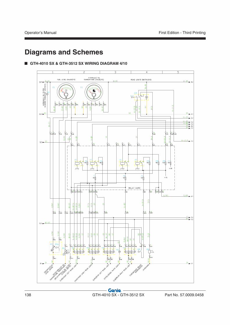
Operator’s Manual
138 GTH-4010 SX - GTH-3512 SX Part No. 57.0009.0458
First Edition - Third Printing
Diagrams and Schemes GTH-4010 SX & GTH-3512 SX WIRING DIAGRAM 4/10
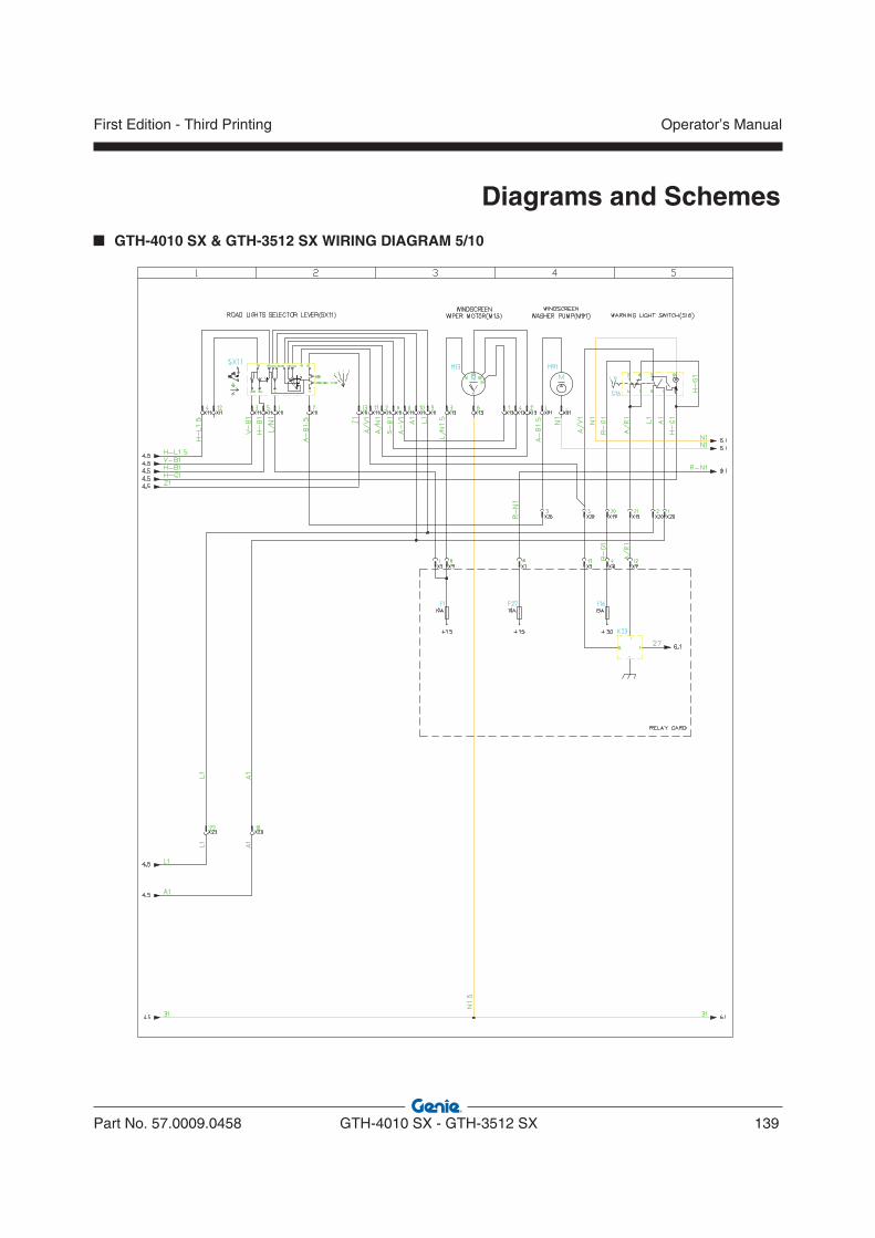
Part No. 57.0009.0458 GTH-4010 SX - GTH-3512 SX 139
Operator’s ManualFirst Edition - Third Printing
Diagrams and Schemes
GTH-4010 SX & GTH-3512 SX WIRING DIAGRAM 5/10
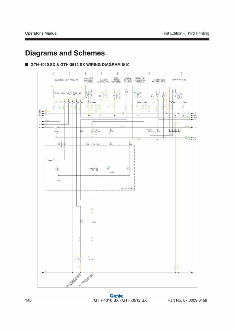
Operator’s Manual
140 GTH-4010 SX - GTH-3512 SX Part No. 57.0009.0458
First Edition - Third Printing
Diagrams and Schemes GTH-4010 SX & GTH-3512 SX WIRING DIAGRAM 6/10
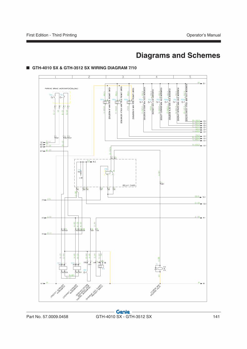
Part No. 57.0009.0458 GTH-4010 SX - GTH-3512 SX 141
Operator’s ManualFirst Edition - Third Printing
Diagrams and Schemes
GTH-4010 SX & GTH-3512 SX WIRING DIAGRAM 7/10
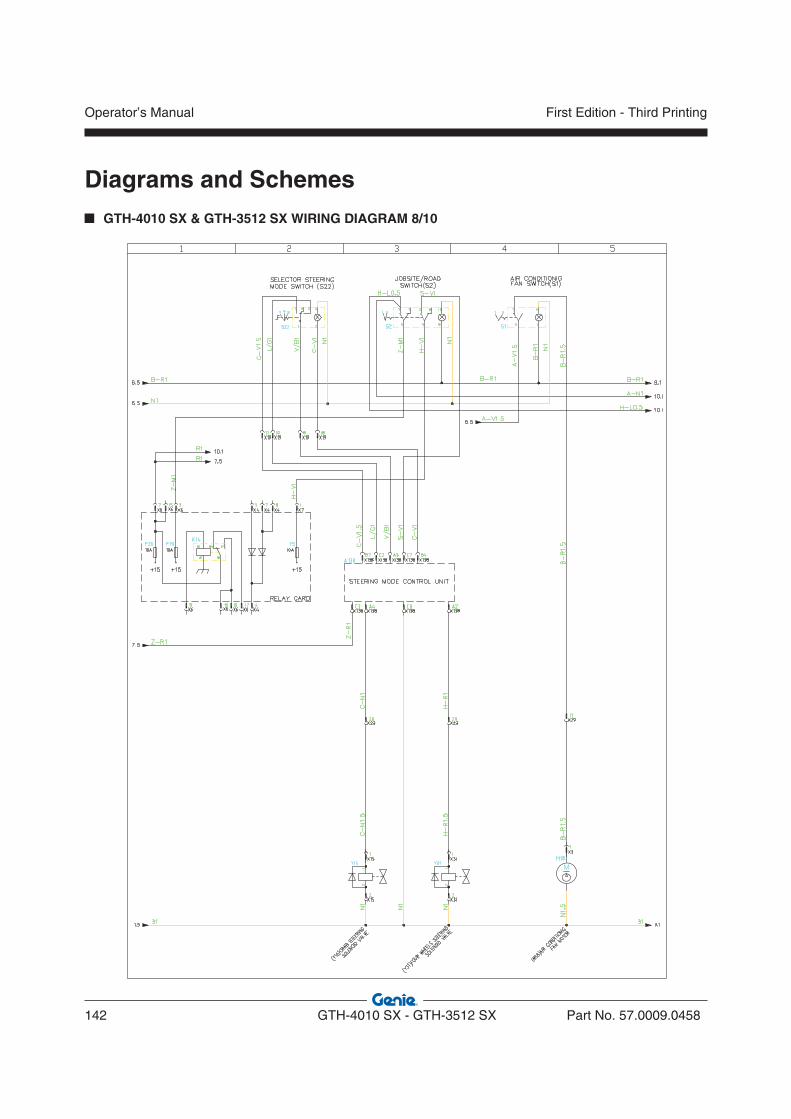
Operator’s Manual
142 GTH-4010 SX - GTH-3512 SX Part No. 57.0009.0458
First Edition - Third Printing
Diagrams and Schemes GTH-4010 SX & GTH-3512 SX WIRING DIAGRAM 8/10
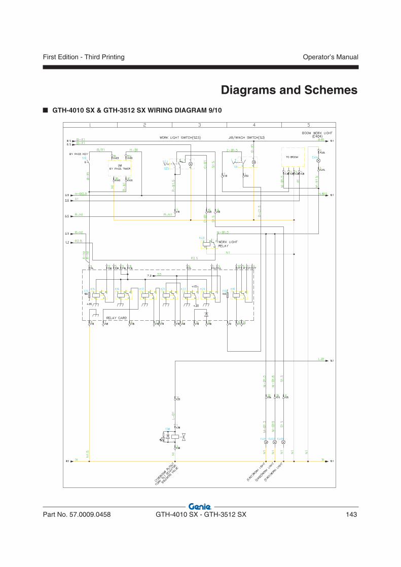
Part No. 57.0009.0458 GTH-4010 SX - GTH-3512 SX 143
Operator’s ManualFirst Edition - Third Printing
Diagrams and Schemes
GTH-4010 SX & GTH-3512 SX WIRING DIAGRAM 9/10
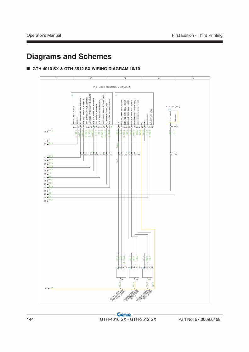
Operator’s Manual
144 GTH-4010 SX - GTH-3512 SX Part No. 57.0009.0458
First Edition - Third Printing
Diagrams and Schemes GTH-4010 SX & GTH-3512 SX WIRING DIAGRAM 10/10
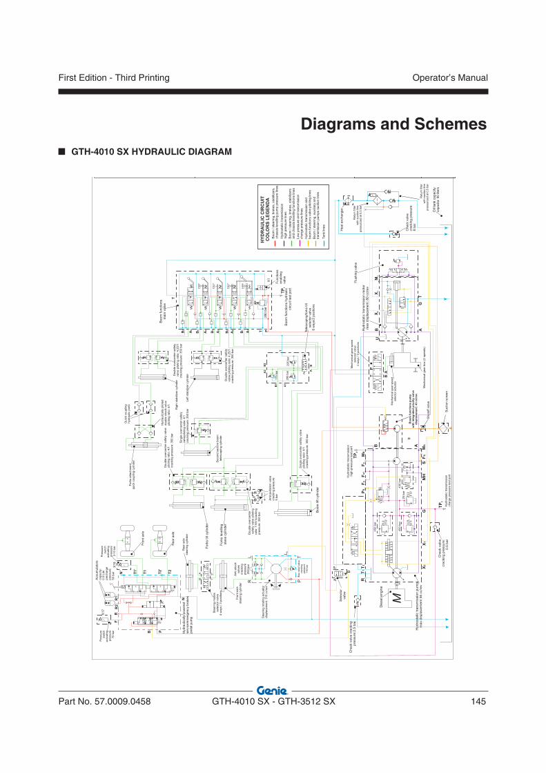
Part No. 57.0009.0458 GTH-4010 SX - GTH-3512 SX 145
Operator’s ManualFirst Edition - Third Printing
Diagrams and Schemes
GTH-4010 SX HYDRAULIC DIAGRAM
M
X1
X2
GM
HS
A
T1
PS
Fa
Fa
1F
eM
BT
2R
N
RF
PB
N’
B
MA
FS
LS
LR
TP
Die
se
l e
ng
ine
Hyd
rosta
tic t
ran
sm
issio
n p
um
pm
ax d
isp
lace
me
nt
56 c
c/r
ev
An
tica
vita
tio
n v
alv
ecra
ckin
g p
ressu
re5
ba
r
Check v
alv
ecra
ckin
g p
ressure
:0.5
bar
Check v
alv
e c
rackin
gpre
ssure
:2.5
ba
r
Oil
tan
k c
ap
acity
capacita: 90 liters
Ste
erin
g r
ota
tin
g a
ctu
ato
rd
isp
lace
me
nt:
31
5 c
c/r
ev
Fo
rks le
ve
llin
gsla
ve
cylin
de
r
Le
ft s
tab
ilize
r cylin
de
r
Rig
ht
sta
bili
ze
r cylin
de
r
Se
co
nd
se
ctio
n b
oo
mte
lesco
pin
g c
ylin
de
r
Bo
om
lift
cylin
de
r
Fo
rks t
ilt c
ylin
de
r
Sin
gle
ove
rce
nte
r sa
fety
va
lve
pilo
tin
g r
atio
: 4
/1cra
ckin
g p
ressu
re:
35
0 b
ar
Do
ub
le o
ve
rce
nte
r sa
fety
va
lve
pilo
tin
g r
atio
: 4
,25
/1cra
ckin
g p
ressu
re:
35
0 b
ar
Do
ub
le o
ve
rce
nte
r sa
fety
va
lve
pilo
tin
g r
atio
: 4
.25
/1cra
ckin
g p
ressu
re:
35
0 b
ar
Do
ub
le o
ve
rce
nte
r sa
fety
va
lve
pilo
tin
g r
atio
: 4
/1cra
ckin
g p
ressu
re:
35
0 b
ar
Do
ub
le o
ve
rce
nte
rsa
fety
va
lve
pilo
tin
gra
tio
: 7
.55
/1cra
ckin
gp
ressu
re:
35
0 b
ar
Sin
gle
ove
rce
nte
r sa
fety
va
lve
pilo
tin
g r
atio
: 4
/1cra
ckin
g p
ressu
re:
35
0 b
ar
450 b
ar
25 b
ar
450 b
ar
430 b
ar
Max r
elie
f valv
ecra
ckin
gpre
ssure
140 b
ar
An
ti-s
ho
ck
va
lve
scra
ckin
gp
ressu
re2
00
ba
r
Qu
ick c
ou
plin
gh
yd
rau
lic p
ort
s
Ste
erin
g m
od
es
se
lecto
r va
lve
4 w
ays /
3 p
ositio
ns
Fro
nt
axle
ste
erin
g c
ylin
de
r
TP
3
TP
2
Hyd
rau
lica
lly p
ilote
dd
ou
ble
ch
eck v
alv
ep
ilotin
g r
atio
: 4
/1
R1
T1
T1’
T2’
T2
R2
T
A P
BAccum
ula
tors
ca
pa
city:
0.5
Litri
pre
ch
arg
ep
ressu
re5
0 b
ar
Hyd
rosta
tic t
ran
sm
issio
nch
arg
e p
ressu
re t
est
po
rt
Hyd
rosta
tic
tra
nsm
issio
nh
igh
pre
ssu
re t
estp
ort
A1
B1
B3
A3
B2
A2
A4
A5
B4
B5
T
T
P
Bo
om
fu
nctio
ns
ma
in v
alv
e
280 b
ar
Functions
enablin
gvalv
eT
P1
Bo
om
fu
nctio
ns h
yd
rau
liccircu
it t
est
po
rt
T
A1
A2
B
B1
B2
A
Tele
scopin
g/fork
s tilt
sele
cto
r valv
e6 w
ays/2
positio
ns
29
5 b
ar
29
5 b
ar
17
5 b
ar
Sele
cto
rvalv
e
P
B
A
A
M1
X1
X2
TG
BU
Hyd
rosta
tic t
ran
sm
issio
n m
oto
rm
ax d
isp
lace
me
nt:
80
cc/r
ev
Flu
shin
g v
alv
e
TP
AB
Me
ch
an
ica
l g
ea
r sp
ee
dse
lecto
r a
ctu
ato
r
Me
ch
an
ica
l g
ea
r sp
ee
dsele
cto
r valv
e4
wa
ys /
3 p
ositio
ns
Me
ch
an
ica
l g
ea
r b
ox (
2 s
pe
ed
s)
HY
DR
AU
LIC
CIR
CU
ITC
OL
OR
S L
EG
EN
DA
Boom
teering, bra
kes, sta
bili
zers
and c
hassis
levelli
ng functions lin
es
/ s
Low
pre
ssure
and tra
nsm
issio
ncharg
e p
ressure
lin
es
Hydro
sta
tic tra
nsm
issio
nhig
h p
ressure
lin
es
Hydro
sta
tic tra
nsm
issio
n a
nd
boom
functions v
alv
e p
iloting lin
es
Boom
teering, bra
kes, sta
bili
zers
,chassis
levelli
ng p
um
p p
ressure
lin
es
/ s
Boom
teering, auxili
ary
and
transm
issio
n p
um
ps s
uction lin
es
/ s
Tank lin
es
Check v
alv
ecra
ckin
g p
ressure
:8 b
ar
Heat exchanger
Re
turn
filt
er
with
su
ctio
n lin
ep
ressu
rize
d a
t 0
,5 b
ar
Re
turn
filt
er
with
su
ctio
n lin
ep
ressu
rize
d a
t 0
,5 b
ar
Pre
ssu
resw
itch
activa
tin
gp
ressu
re7
0 b
ar
Hydra
ulic
ally
pow
ere
dserv
ice/e
merg
ency b
rakes
pedal pum
p
Pre
ssu
resw
itch
activa
tin
gp
ressu
re2
-10
ba
r
Rear
axle
Fro
nt axle
Re
ar
axle
ste
erin
g c
ylin
de
r
Fo
rks a
tta
ch
me
nt
qu
ick c
ou
plin
g c
ylin
de
r
X1
7
X1
8
X1
Suction s
cre
en
Sh
uto
ff v
alv
e
BB
oo
m f
un
cti
on
s p
um
pw
ith
in
teg
rate
d p
rio
rity
va
lve
dis
pla
ce
me
nt:
43
cc
/re
v

Operator’s Manual
146 GTH-4010 SX - GTH-3512 SX Part No. 57.0009.0458
First Edition - Third Printing
Diagrams and Schemes
GTH-3512 SX HYDRAULIC DIAGRAM
M
X1
X2
GM
HS
A
T1
PS
Fa
Fa
1F
eM
BT
2R
N
RF
PB
N’
B
MA
FS
LS
LR
TP
Die
se
l e
ng
ine
Hyd
rosta
tic t
ran
sm
issio
n p
um
pm
ax d
isp
lace
me
nt
56 c
c/r
ev
An
tica
vita
tio
n v
alv
ecra
ckin
g p
ressu
re5
ba
r
Check v
alv
ecra
ckin
g p
ressure
:0.5
bar
Check v
alv
e c
rackin
gpre
ssure
:2.5
ba
r
Oil
tan
k c
ap
acity
capacita: 90 liters
Ste
erin
g r
ota
tin
g a
ctu
ato
rd
isp
lace
me
nt:
31
5 c
c/r
ev
Fo
rks le
ve
llin
gsla
ve
cylin
de
r
Th
ird
se
ctio
n b
oo
mte
lesco
pin
g c
ylin
de
r
Le
ft s
tab
ilize
r cylin
de
r
Rig
ht
sta
bili
ze
r cylin
de
r
Se
co
nd
se
ctio
n b
oo
mte
lesco
pin
g c
ylin
de
r
Bo
om
lift
cylin
de
r
Fo
rks t
ilt c
ylin
de
r
Sin
gle
ove
rce
nte
r sa
fety
va
lve
pilo
tin
g r
atio
: 4
/1cra
ckin
g p
ressu
re:
35
0 b
ar
Do
ub
le o
ve
rce
nte
r sa
fety
va
lve
pilo
tin
g r
atio
: 4
/1cra
ckin
g p
ressu
re:
35
0 b
ar
Do
ub
le o
ve
rce
nte
r sa
fety
va
lve
pilo
tin
g r
atio
: 4
,25
/1cra
ckin
g p
ressu
re:
35
0 b
ar
Do
ub
le o
ve
rce
nte
r sa
fety
va
lve
pilo
tin
g r
atio
: 4
.25
/1cra
ckin
g p
ressu
re:
35
0 b
ar
Do
ub
le o
ve
rce
nte
r sa
fety
va
lve
pilo
tin
g r
atio
: 4
/1cra
ckin
g p
ressu
re:
35
0 b
ar
Do
ub
le o
ve
rce
nte
rsa
fety
va
lve
pilo
tin
gra
tio
: 7
.55
/1cra
ckin
gp
ressu
re:
35
0 b
ar
Sin
gle
ove
rce
nte
r sa
fety
va
lve
pilo
tin
g r
atio
: 4
/1cra
ckin
g p
ressu
re:
35
0 b
ar
450 b
ar
25 b
ar
450 b
ar
430 b
ar
Max r
elie
f valv
ecra
ckin
gpre
ssure
140 b
ar
An
ti-s
ho
ck
va
lve
scra
ckin
gp
ressu
re2
00
ba
r
Qu
ick c
ou
plin
gh
yd
rau
lic p
ort
s
Ste
erin
g m
od
es
se
lecto
r va
lve
4 w
ays /
3 p
ositio
ns
Fro
nt
axle
ste
erin
g c
ylin
de
r
TP
3
TP
2
Hyd
rau
lica
lly p
ilote
dd
ou
ble
ch
eck v
alv
ep
ilotin
g r
atio
: 4
/1
R1
T1
T1’
T2’
T2
R2
T
A P
BAccum
ula
tors
ca
pa
city:
0.5
Litri
pre
ch
arg
ep
ressu
re5
0 b
ar
Hyd
rosta
tic t
ran
sm
issio
nch
arg
e p
ressu
re t
est
po
rt
Hyd
rosta
tic
tra
nsm
issio
nh
igh
pre
ssu
re t
estp
ort
A1
B1
B3
A3
B2
A2
A4
A5
B4
B5
T
T
P
Bo
om
fu
nctio
ns
ma
in v
alv
e
280 b
ar
Functions
enablin
gvalv
eT
P1
Bo
om
fu
nctio
ns h
yd
rau
liccircu
it t
est
po
rt
T
A1
A2
B
B1
B2
A
Tele
scopin
g/fork
s tilt
sele
cto
r valv
e6 w
ays/2
positio
ns
29
5 b
ar
29
5 b
ar
17
5 b
ar
Sele
cto
rvalv
e
P
B
A
A
M1
X1
X2
TG
BU
Hyd
rosta
tic t
ran
sm
issio
n m
oto
rm
ax d
isp
lace
me
nt:
80
cc/r
ev
Flu
shin
g v
alv
e
TP
AB
Me
ch
an
ica
l g
ea
r sp
ee
dse
lecto
r a
ctu
ato
r
Me
ch
an
ica
l g
ea
r sp
ee
dse
lecto
r va
lve
4 w
ays /
3 p
ositio
ns
Me
ch
an
ica
l g
ea
r b
ox (
2 s
pe
ed
s)
HY
DR
AU
LIC
CIR
CU
ITC
OL
OR
S L
EG
EN
DA
Boom
teering, bra
kes, sta
bili
zers
and c
hassis
levelli
ng functions lin
es
/ s
Low
pre
ssure
and tra
nsm
issio
ncharg
e p
ressure
lin
es
Hydro
sta
tic tra
nsm
issio
nhig
h p
ressure
lin
es
Hydro
sta
tic tra
nsm
issio
n a
nd
boom
functions v
alv
e p
iloting lin
es
Boom
teering, bra
kes, sta
bili
zers
,chassis
levelli
ng p
um
p p
ressure
lin
es
/ s
Boom
teering, auxili
ary
and
transm
issio
n p
um
ps s
uction lin
es
/ s
Tank lin
es
Check v
alv
ecra
ckin
g p
ressure
:8
ba
r
Heat exchanger
Re
turn
filt
er
with
su
ctio
n lin
ep
ressu
rize
d a
t 0
,5 b
ar
Re
turn
filt
er
with
su
ctio
n lin
ep
ressu
rize
d a
t 0
,5 b
ar
Pre
ssu
resw
itch
activating
pre
ssu
re7
0 b
ar
Hydra
ulic
ally
pow
ere
dserv
ice/e
merg
ency b
rakes
pedal pum
p
Pre
ssu
resw
itch
activa
tin
gp
ressu
re2
-10
ba
r
Rear
axle
Fro
nt axle
Re
ar
axle
ste
erin
g c
ylin
de
r
Fo
rks a
tta
ch
me
nt
qu
ick c
ou
plin
g c
ylin
de
r
X1
7
X1
8
X1
Suction s
cre
en
Sh
uto
ff v
alv
e
BB
oo
m f
un
cti
on
s p
um
pw
ith
in
teg
rate
d p
rio
rity
va
lve
dis
pla
ce
me
nt:
43
cc
/re
v
Warranty LIMITED PRODUCT WARRANTY
Genie Industries (“Seller”) warrants its new equipment manufactured and sold worldwide, to be free, under normal use and service, of any defects in manufacture or materials for the following time periods, commencing on the date on which such equipment is invoiced to the original purchaser or the date on which such equipment is first put into service, whichever occurs first:
• with respect to structural elements: 5 years; • with respect to electrical componentry: 2
years • with respect to hydraulic componentry (except
as provided below): 2 years • with respect to o-rings, seals, hoses and
brakes: 1 year
provided that:
1. Seller receives written notice of the defect within fourteen (14) days of its discovery and Buyer establishes that
i. the equipment has been maintained and operated within the limits of rated and normal usage
ii. the defect did not result in any manner from the intentional or negligent action or inaction by Buyer, its agents or employees
2. a new machine registration certificate has been completed, signed and delivered to Seller within fourteen (14) days of the equipment’s “in-service” date.
If requested by Seller, Buyer must return the defective equipment to Seller’s manufacturing facility, or other location designated by Seller, for inspection, and if Buyer cannot establish that conditions (1) (i) and(1) (ii) above have been met, then this warranty shall not cover the alleged defect. Delivery inspection certificates are required to be completed, signed and delivered to Seller within one hundred twenty (120) days of the equipment’s “in-service” date and on file with Seller’s service department for warranty validation and processing.Seller’s obligation and liability under this warranty is
expressly limited to, at Seller’s sole option, repairing or replacing, with new or remanufactured parts or components, any part, which appears to Seller upon inspection to have been defective in material or workmanship.Such parts shall be provided at no cost to the owner, FOB Seller’s parts facility. If requested by Seller, components or parts for which a warranty claim is made shall be returned to Seller at a location designated by Seller. All components and parts replaced under this limited product warranty become the property of Seller.This warranty shall be null and void if parts (including wear parts) other than genuine OEM Seller parts are used in the equipment.Accessories, assemblies and components included in the Seller equipment, which are not manufactured by Seller, are subject to the warranty of their respective manufacturers.Normal maintenance, adjustments, or maintenance/wear parts, including without limitation, glass, clutch and brake linings, filters, wire rope and paint, are not covered by this warranty and are the sole maintenance responsibility of Buyer.
Seller makes no other warranty, express or implied, and makes no warranty of merchantability or fitness for any particular purpose.
Seller’s obligation under this warranty shall not include duty, taxes, environmental fees, including without limitation, disposal or handling of tires, batteries, petrochemical items, or any other charges whatsoever, or any liability for direct, indirect, incidental, or consequential damages.Improper maintenance, improper use, abuse, improper storage, operation beyond rated capacity, operation after discovery of defective or worn parts, accident, sabotage or alteration or repair of the equipment by persons not authorized by Seller shall render this warranty null and void.
Part No. 57.0009.0458 GTH-4010 SX - GTH-3512 SX 147
Operator’s ManualFirst Edition - Third Printing

ITEMS NOT COVERED BY SELLER WARRANTY
The following items are not covered under the seller warranty (the following list is not Exhaustive):1. Lamps, lenses, filters, consumable items, utility
trailer decks, shop supplies.2. Items sold by any individual, corporation,
partnership or any other organization or legal Entity that is not an authorized seller distributor.
3. Components which are not manufactured by seller are not covered by seller’s warranty. Such components are covered only by the warranty, if any, that is provided by the Manufacturer of such components. Such components may include, but are not limited to, Engines, batteries, tires, customer-supplied products, transmissions, generators/gensets, Axles.
4. Replacement of Assemblies: seller has the option to repair or replace any defective part or assembly. It is seller’s policy to refuse claims for the replacement of a complete assembly that is field repairable by the replacement or repair of defective part(s) within the assembly.
5. Normal Operational Maintenance Services and Wear Parts: maintenance services and wear parts are excluded from warranty claims. Maintenance services and wear parts not covered include, but are not limited to, such items as: seals, gaskets, hoses, glass, clutch and brake linings, wire rope, exterior coatings, proper tightening of bolts, nuts and fittings, adding or replacing of fluids, breathers, belts, nozzles, adjustments of any kind, services supplies such as lubricants, inspections, diagnostic time, travel time.
6. Transportation Cost and/ or Damage: any damage caused by carrier handling is a transportation claim and should be filed immediately with the respective carrier.
7. Deterioration: repairs, work required or parts exposed as the result of age, storage, weathering, lack of use, demonstration use, or use for transportation of corrosive chemicals.
Warranty
Seller reserves the right to inspect the installation of the product and review maintenance procedures to determine if the failure was due to improper maintenance, improper use, abuse, improper storage, operation beyond rated capacity, operation after discovery of defective or worn parts, or alteration or repair of the equipment by persons not authorized by Seller.
NO TRANSFERABILITY OF WARRANTY: This warranty is limited to the original end-user and is not assignable or otherwise transferable without the written agreement of Seller.
Operator’s Manual
148 GTH-4010 SX - GTH-3512 SX Part No. 57.0009.0458
First Edition - Third Printing

8. Secondary Failures: should the owner or operator continue to operate a machine after It has been noted that a failure has occurred, seller will not be responsible under the warranty for resultant damage to other parts due to that continued operation.
9. Workmanship of Others: seller does not accept responsibility for improper installation or labor costs or costs of any kind from personnel other than personnel authorized by seller.
10. Stop and Go Warranty: seller does not recognize “stop and go” warranties.
11. Incidental or Consequential Damage: SELLER SHALL NOT BE LIABLE FOR ANY INCIDENTAL OR CONSEQUENTIAL DAMAGES OF ANY KIND, INCLUDING, BUT NOT LIMITED TO, LOST PROFITS, LOSS OF PRODUCTION, INCREASED OVERHEAD, LOSS OF BUSINESS OPPORTUNITY, DELAYS IN PRODUCTION, COSTS OF REPLACEMENT COMPONENTS AND INCREASED COSTS OF OPERATION THAT MAY ARISE FROM THE BREACH OF THIS WARRANTY. Customer’s sole remedy shall be limited to (at seller’s sole option) repair or replacement of the defective part.
THIS WARRANTY IS EXPRESSLY IN LIEU OF AND EXCLUDES ALL OTHER WARRANTIES, EXPRESS OR IMPLIED (INCLUDING THE WARRANTIES OF MERCHANTABILITY AND FITNESS FOR A PARTICULAR PURPOSE) AND ALL OTHER OBLIGATIONS OR LIABILITY ON SELLER’S PART. THERE ARE NO WARRANTIES THAT EXTEND BEYOND THE LIMITED WARRANTY CONTAINED HEREIN. Seller neither assumes nor authorizes any other person to assume for seller any other liability in connection with the sale of seller’s equipment. This warranty shall not apply to any of seller’s equipment or any part thereof which has been subject to misuse, alteration, abuse, negligence, accident, acts of god or sabotage.
No action by any party shall operate to extend or revive this limited warranty without the prior written consent of seller. In the event that any provision of this warranty is held unenforceable for any reason, the remaining provisions shall remain in full force and effect.
IN THE EVENT OF ANY BREACH OF THE WARRANTY BY SELLER, SELLER’S LIABILITY SHALL BE LIMITED EXCLUSIVELY TO THE REMEDIES (AT SELLER’S SOLE OPTION) OF REPAIR OR REPLACEMENT OF ANY DEFECTIVE EQUIPMENT COVERED BY THE WARRANTY. IN NO EVENT SHALL SELLER, OR ANY SUBSIDIARY OR DIVISION THEREOF BE LIABLE FOR INCIDENTAL, INDIRECT, CONSEQUENTIAL OR OTHER DAMAGES OR LOSSES RESULTING FROM A BREACH OF WARRANTY INCLUDING, WITHOUT LIMITATION, LABOR COSTS, LOSS OF USE OF OTHER EQUIPMENT, THIRD PARTY REPAIRS, LOST PROFITS, LOST TIME, TOWING OR HAULING OF EQUIPMENT, RENTAL COSTS, PERSONAL INJURY, EMOTIONAL OR MENTAL DISTRESS, IMPROPER PERFORMANCE OR WORK, PENALTIES OF ANY KIND, LOSS OF SERVICE OF PERSONNEL, OR FAILURE OF EQUIPMENT TO COMPLY WITH ANY FEDERAL, STATE OR LOCAL LAWS.
Warranty
Part No. 57.0009.0458 GTH-4010 SX - GTH-3512 SX 149
Operator’s ManualFirst Edition - Third Printing

Intentionally blank page
Operator’s Manual
150 GTH-4010 SX - GTH-3512 SX Part No. 57.0009.0458
First Edition - Third Printing
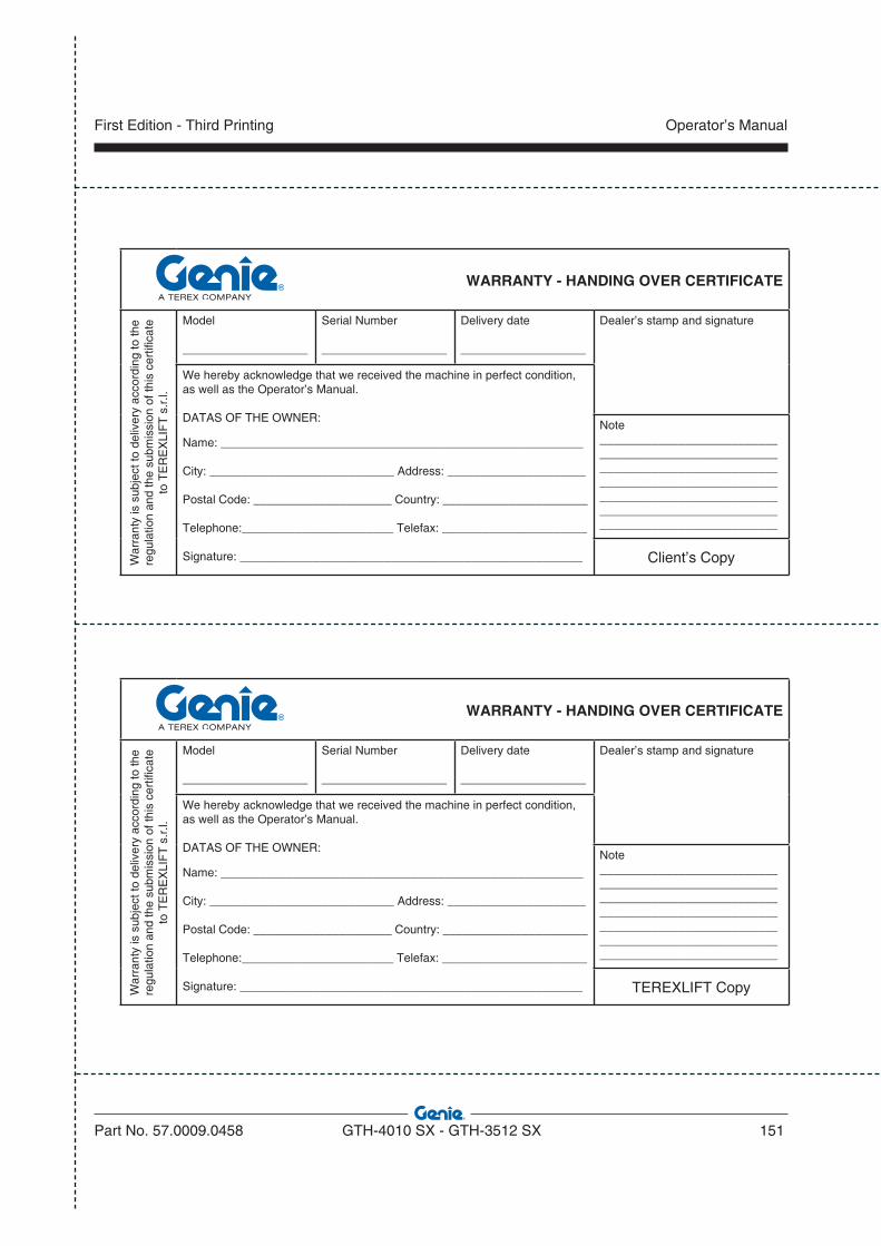
WARRANTY - HANDING OVER CERTIFICATE
War
rant
y is
sub
ject
to d
eliv
ery
acco
rdin
g to
the
regu
latio
n an
d th
e su
bmis
sion
of t
his
cert
ifica
te
to T
ER
EX
LIF
T s
.r.l.
Model
___________________
Serial Number
___________________
Delivery date
___________________
Dealer’s stamp and signature
We hereby acknowledge that we received the machine in perfect condition, as well as the Operator’s Manual.
DATAS OF THE OWNER:
Name: _______________________________________________________
City: ____________________________ Address: _____________________
Postal Code: _____________________ Country: ______________________
Telephone:_______________________ Telefax: ______________________
Signature: ____________________________________________________
Note_____________________________________________________________________________________________________________________________________________________________________________________________
Client’s Copy
WARRANTY - HANDING OVER CERTIFICATE
War
rant
y is
sub
ject
to d
eliv
ery
acco
rdin
g to
the
regu
latio
n an
d th
e su
bmis
sion
of t
his
cert
ifica
te
to T
ER
EX
LIF
T s
.r.l.
Model
___________________
Serial Number
___________________
Delivery date
___________________
Dealer’s stamp and signature
We hereby acknowledge that we received the machine in perfect condition, as well as the Operator’s Manual.
DATAS OF THE OWNER:
Name: _______________________________________________________
City: ____________________________ Address: _____________________
Postal Code: _____________________ Country: ______________________
Telephone:_______________________ Telefax: ______________________
Signature: ____________________________________________________
Note_____________________________________________________________________________________________________________________________________________________________________________________________
TEREXLIFT Copy
Part No. 57.0009.0458 GTH-4010 SX - GTH-3512 SX 151
Operator’s ManualFirst Edition - Third Printing