Embed Size (px)
Citation preview
� Photonik international · �008/1 Originally published in German in Photonik 1/�007
From micro to macro: NIR sensors and imaging spectroscopy – a perfect matchBob Grietens, XenICs NV, Leuven, Belgium
Image capture in the near-infrared spectrum (NIR) at wavelengths up to 2.5 µm is gaining ever greater economic significance. This is especially true in regard to imaging spectroscopy: hyperspectral microscopes, for exam-ple, can accelerate the design process of new kinds of LED structures; mul-tispectral online inspection of recyclable materials ensures unmixed waste separation [1]; and finally, in the arts, multispectral reflectography serves as a tool for revealing the secrets of old masters and their works.
Optical Metrology
With the introduction of InGaAs as a detector material ten years ago, infrared image capture moved out of the research laboratory and is now conquering more and more industrial applications - even in cost-sensitive areas. InGaAs array sensors deliver good results in the near infrared up to 1.7 µm, even at room temperature, and with thermo-electrical (TE) cooling they can be operated up to a wavelength of �.5 µm – a real alternative to HgCdTe detectors.
1 Sensor array technology
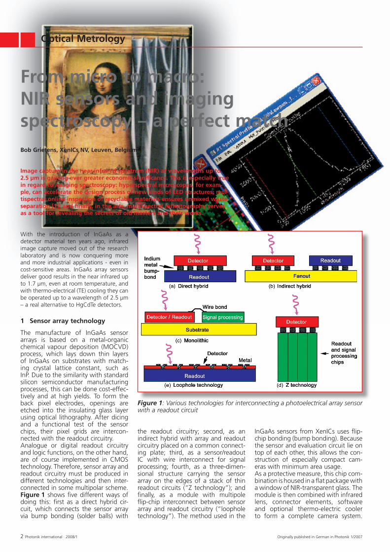
The manufacture of InGaAs sensor arrays is based on a metal-organic chemical vapour deposition (MOCVD) process, which lays down thin layers of InGaAs on substrates with match-ing crystal lattice constant, such as InP. Due to the similarity with standard silicon semiconductor manufacturing processes, this can be done cost-effec-tively and at high yields. To form the back pixel electrodes, openings are etched into the insulating glass layer using optical lithography. After dicing and a functional test of the sensor chips, their pixel grids are intercon-nected with the readout circuitry. Analogue or digital readout circuitry and logic functions, on the other hand, are of course implemented in CMOS technology. Therefore, sensor array and readout circuitry must be produced in different technologies and then inter-connected in some multipolar scheme. Figure 1 shows five different ways of doing this: first as a direct hybrid cir-cuit, which connects the sensor array via bump bonding (solder balls) with
Figure 1: Various technologies for interconnecting a photoelectrical array sensor with a readout circuit
the readout circuitry; second, as an indirect hybrid with array and readout circuitry placed on a common connect-ing plate; third, as a sensor/readout IC with wire interconnect for signal processing; fourth, as a three-dimen-sional structure carrying the sensor array on the edges of a stack of thin readout circuits (“Z technology”); and finally, as a module with multipole flip-chip interconnect between sensor array and readout circuitry (“loophole technology”). The method used in the
InGaAs sensors from XenICs uses flip-chip bonding (bump bonding). Because the sensor and evaluation circuit lie on top of each other, this allows the con-struction of especially compact cam-eras with minimum area usage. As a protective measure, this chip com-bination is housed in a flat package with a window of NIR-transparent glass. The module is then combined with infrared lens, connector elements, software and optional thermo-electric cooler to form a complete camera system.

Optical Metrology
Photonik international · �008/1 �Originally published in German in Photonik 1/�007
Figure 2: The path from monochrome image to multispectral colour capture to hyperspectral data cube
2 Hyperspectral analysis technology
Imaging spectroscopy or hyperspectral analysis is a successful combination of spectroscopy and image processing. As shown in Figure 2, it can be seen as an extension of classic image process-ing. In the most simple configuration, a black-and-white camera captures a greyscale view of objects - at high spatial resolution but without deliver-ing any spectral information. Next, a colour camera with three image sen-sors, or one sensor with a Bayer colour filter, does considerably better because it delivers a multispectral image at a comparably high spatial resolution plus three fairly broadband colour chan-nels, for example for red, green and blue; but it offers only a relatively low spectral resolution. Finally, systems that capture spectral images either work with one sensor and a tunable narrow-pass filter for frequency selec-tion inserted into the optical path, or they apply the so-called push-broom scanner principle. A push-broom scan-ner, usually via mechanical feed of the test object or spectrometer, performs a line scan of the object. For every image element in a particular line, the spec-trum is captured and then stored in a pixel column of the detector. Both methods depend on their large number of colour channels, which is why they are called “hyperspectral”: They deliver high spatial as well as high spectral resolutions. The values for the X and Y coordinates and their spectral
components are situated in a three-dimensional data space (cube), as indi-cated in the top right of Figure �. NIR image sensors, due to their high resolution and broadband nature, are very well suited for this type of hyper-spectral analytical equipment – going far beyond the mere imaging function in a camera. Figure 3 shows the work-ing principle of a direct-view spectral camera with a grating as the dispersive element. This combination of inte-grated spectrograph and monochrome matrix camera basically functions as a line camera that fans out the spec-trum. For each one of its sequentially organized linear pixels, the spectrum is generated and captured as an intensity pattern on the vertical axis (spectrum axis) of the sensor array. The horizontal axis is kept as the geometry axis. By moving the object or the camera, a two-dimensional image can be gener-ated, which will yield certain properties based on its spectral intensity distribu-
tion. This, in turn, can be used for clas-sification purposes or for process con-trol. But unlike using a spectrometer, this spatial resolution method delivers image information as well.
3 Hyperspectral microscope accelerates the design of specialty LEDs
Oftentimes, topically relevant research and development projects act as driv-ers for innovations in related technical equipment. At Twente University, for example, ongoing research investigates the impact of electrical fields on lateral LED structures. This is done by placing an additional gate electrode on top of the active light-emitting region. Now, operating this diode with con-stant current and negative bias at the gate electrode lets it shine brighter, and the intensity profile of the radiat-ing surface also changes substantially. Thus, the light emission of an LED can be specifically varied via an MOS gate – enabling innovative applications in illumination, measurement and auto-mation technologies. For a thorough understanding of the underlying effects, such structures must be modelled and compared with experimental results. The more precise and informative these comparative measurements are, the more accurate the modelling will be. Often it is not sufficient to measure just the intensity across the individual area elements: The measured intensity must be com-plemented by the spectral distribution of the radiation at a sufficient spa-tial resolution. Solving this problem therefore requires the methodology of imaging spectroscopy in micrometers.With this in mind, Twente Univer-sity and XenICs have jointly developed the mobile hyperspectral microscope (HIMS) shown in Figure 4. It is par-ticularly well suited for research work on light-emitting semiconductor struc-tures that radiate in the near infrared.By means of a beam splitter, about a third of the emission is directed toward a laterally positioned CCD camera, which serves to align the microscope and select the object’s surface of interest. The IR camera is mounted on this structure with a transmission spectrograph (Figure �) from Finnish manufacturer Specim preceding it. The water-cooled (fan-free and light) cam-era head can be moved line by line �5 mm above the test object via a stepper motor.
Figure 3: Working principle of the spectral camera: a combination of imaging spectrograph (ImSpector from Spectral Imaging) and matrix camera
Fig. 4: The structure of the hyperspectral microscope at Twente University

Optical Metrology
� Photonik international · �008/1 Originally published in German in Photonik 1/�007
The spectrograph’s dispersion element is a grating with more than 50% transparency and a spectral resolution of 5 nm in the NIR range from 900 to 1700 nm. The microscope’s IR lens projects the area to be measured on the test object onto the entry slit of the spectrograph. There, the incoming light is spectrally dispersed and the spatial axis as well as the orthogonal spectral axis are coupled out through a lens onto the NIR array sensor.One of the first images taken with this hyperspectral microscope is shown in Figure 5. It shows the spectral analysis of an LED structure in the ENVI (envi-ronment for visualizing images) realm. To the left is a three-channel false-col-our depiction, with an arbitrarily select-ed analysis coordinate. To the right is the pertinent spectral profile. It can be clearly seen that a mere three-channel “multispectral” analysis conveys only very sketchy and limited information. This examination method is applicable to all materials and structures that can be pictured through a microscope and are somehow characterised by their spectral information. The instantane-ous and informative results yielded by this method can help accelerate the designing of new products and quicken the pace of innovation.
4 Secrets of old masters revealed by hyperspectral analysis
Besides their obvious industrial appli-cations, NIR array sensors can also be advantageous in the scientific realm, as an art-related example will prove.
For a long time, infrared images have served as analytical tools in art history, in the restoration and authentication of art works, or to assign anonymous works to specific periods. Moreover, infrared analysis is often used to determine whether there are underdrawings present in oil and tem-pera paintings (Figure 6). Due to its low IR absorption, longer-wave radia-tion offers a simple and, above all, non-destructive method of “looking through” the upper layers of a paint-ing to recognize and evaluate any underlying structures, drafts or previ-ous versions.Underdrawings are outlines lying directly beneath a painting, often done in charcoal. At a later stage these drawings are mostly hidden by the final layer of paint. Painters use underdrawings in their own individual ways: from simple perspective layouts to detailed sketches. Underdrawings can thus provide deeper insights into the creative process of the artist.It very much depends on the absorptive and reflective behaviour (Figure 7) of the underdrawing and the overlying layers of paint whether there is suf-ficient optical contrast to distinguish between them. Since the absorption of most materials depends heavily on the frequency, modern analysis proce-dures are tending toward using several different spectral ranges by using mul-tispectral reflectography. They evaluate digital images taken in the realm of vis-ible light, in the NIR between 0.8 und 1.1 µm, as well in the extended infrared between 1.� und �.� µm. Ideally, these images are overlaid on the computer and processed with appropriate algo-rithms to enhance contrast and uncover any underdrawings for analysis.When selecting a suitable image sen-sor for taking such digital IR pictures, therefore, the first priority is to make sure it offers sufficient sensitivity in the NIR range. At the same time, however, the often difficult operating conditions for such imaging tasks must be met,
and this requires a light, low-cost camera which is easy to use.
5 Conclusion
Thanks to their inherently advanta-geous properties such as uncooled or TE-cooled operation, low operating costs, high sensitivity, small dimensions and high usage flexibility, InGaAs NIR image sensors enable innovative solu-tions in the most diverse areas of appli-cation. Thus they are establishing new trends as well as new benchmarks for more economical processes in design, manufacturing, process control and services.
References:[1] Bob Grietens, Spektrale Schatzsuche im NIR mit
ungekühlten InGaAsKameras, Photonik 1/�006, p. 78-79.
[�] Jean Margat, Le mythe de la Joconde, ISBN �-8�89-05�7-0, p. �5.
[�] Chad Weiner, Improved Acquisition Technique of Underdrawings in Oil Paintings using IRReflectography, www.cis.rit.edu/research/thesis/bs/1999/weiner/thesis.html
Author contact:
Bob GrietensCEOXenICs NVAmbachtenlaan ���001 LeuvenBelgiumTel. +��/16/�89900Fax +��/16/�89901eMail: [email protected]: www.xenics.com
Figure 5: Significant spectrum content of a point of the LED in the crosshairs
Figure 6: The painting “La Joconde impudique” by Pierre Gilou as an example of a possible underdrawing of the bosom, arms and hands of the Mona Lisa [2]
Figure 7: Reflection and absorption of light in the paint layer of a picture [3]