Embed Size (px)
Citation preview
1 © Nokia Siemens Networks
R 255
G 211
B 8
R 255
G 175
B 0
R 127
G 16
B 162
R 163
G 166
B 173
R 137
G 146
B 155
R 175
G 0
B 51
R 52
G 195
B 51
R 0
G 0
B 0
R 255
G 255
B 255
Primary colours: Supporting colours:
From customer requirements to test architecture Nordic Test Forum (NTF) 2011
November 22th – 23th 2011
Tuusula, FINLAND
http://NordicTestForum.org
Vesa Hekkala
2 © Nokia Siemens Networks
R 255
G 211
B 8
R 255
G 175
B 0
R 127
G 16
B 162
R 163
G 166
B 173
R 137
G 146
B 155
R 175
G 0
B 51
R 52
G 195
B 51
R 0
G 0
B 0
R 255
G 255
B 255
Primary colours: Supporting colours:
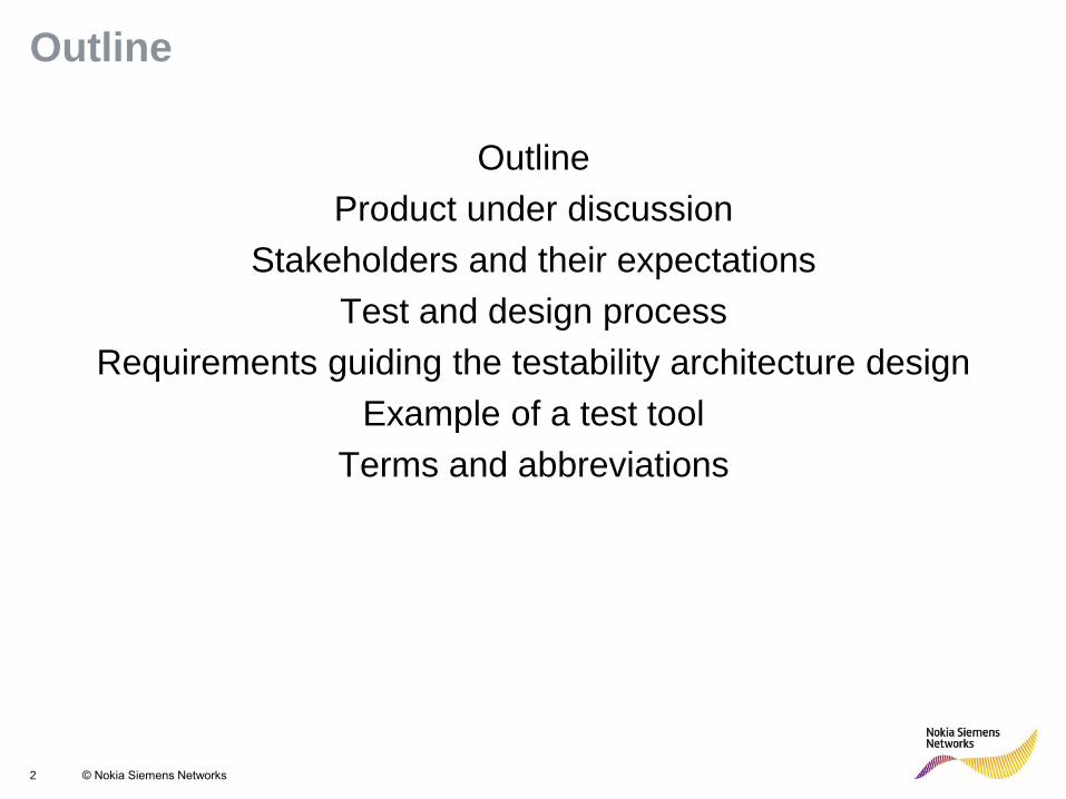
Outline
Outline
Product under discussion
Stakeholders and their expectations
Test and design process
Requirements guiding the testability architecture design
Example of a test tool
Terms and abbreviations
3 © Nokia Siemens Networks
R 255
G 211
B 8
R 255
G 175
B 0
R 127
G 16
B 162
R 163
G 166
B 173
R 137
G 146
B 155
R 175
G 0
B 51
R 52
G 195
B 51
R 0
G 0
B 0
R 255
G 255
B 255
Primary colours: Supporting colours:
Outline
Outline
Product under discussion
Stakeholders and their expectations
Test and design process
Requirements guiding the testability architecture design
Example of a test tool
Terms and abbreviations
4 © Nokia Siemens Networks
R 255
G 211
B 8
R 255
G 175
B 0
R 127
G 16
B 162
R 163
G 166
B 173
R 137
G 146
B 155
R 175
G 0
B 51
R 52
G 195
B 51
R 0
G 0
B 0
R 255
G 255
B 255
Primary colours: Supporting colours:
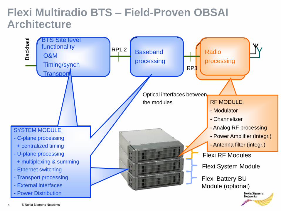
Flexi Multiradio BTS – Field-Proven OBSAI Architecture
Baseband
processing RP3
RP1,2 Radio
processing Ba
ckh
au
l
BTS Site level functionality
O&M
Timing/synch
Transport
Flexi RF Modules
Flexi System Module
Optical interfaces between
the modules RF MODULE:
- Modulator
- Channelizer
- Analog RF processig
- Power Amplifier (integr.)
- Antenna filter (integr.)
RF MODULE:
- Modulator
- Channelizer
- Analog RF processing
- Power Amplifier (integr.)
- Antenna filter (integr.)
Flexi Battery BU
Module (optional)
SYSTEM MODULE:
- C-plane processing
+ centralized timing
- U-plane processing
+ multiplexing & summing
- Ethernet switching
- Transport processing
- External interfaces
- Power Distribution
5 © Nokia Siemens Networks
R 255
G 211
B 8
R 255
G 175
B 0
R 127
G 16
B 162
R 163
G 166
B 173
R 137
G 146
B 155
R 175
G 0
B 51
R 52
G 195
B 51
R 0
G 0
B 0
R 255
G 255
B 255
Primary colours: Supporting colours:
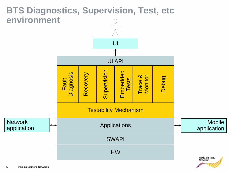
BTS Diagnostics, Supervision, Test, etc environment
SWAPI
HW
Applications Network application
Mobile application
UI
UI API
Superv
isio
n
Recovery
Em
bedded
Tests
Tra
ce &
M
onitor
Debug
Fault
Dia
gnosis
Testability Mechanism
6 © Nokia Siemens Networks
R 255
G 211
B 8
R 255
G 175
B 0
R 127
G 16
B 162
R 163
G 166
B 173
R 137
G 146
B 155
R 175
G 0
B 51
R 52
G 195
B 51
R 0
G 0
B 0
R 255
G 255
B 255
Primary colours: Supporting colours:
Outline
Outline
Product under discussion
Stakeholders and their expectations
Test and design process
Requirements guiding the testability architecture design
Example of a test tool
Terms and abbreviations

7 © Nokia Siemens Networks
R 255
G 211
B 8
R 255
G 175
B 0
R 127
G 16
B 162
R 163
G 166
B 173
R 137
G 146
B 155
R 175
G 0
B 51
R 52
G 195
B 51
R 0
G 0
B 0
R 255
G 255
B 255
Primary colours: Supporting colours:
What is DFT - stakeholder expectations
BTS DFT is ?
HW testability
System testability
SW testability
Production
Life time (HW) verification
HW R&D
HW verification
functionality & performance
BIST, POST
Product
mgmnt
Get state of art
testability with no
impact to time
schedule –
higher priority for
“customer
features”
Architecture
Requirements
Design
Test tools
SW R&D
Detailed debugging
information (logs, traces
dumps)
Interface simulators,
emulators
Repair center
HW fault
localization,
down to component
level
Operator
(customer)
Autonomous fault detection
and recovery.
Fault localization and test
coverage to unit/module and
interface level.
I&V
White box testability
aids to trace SW
functionality.
Interface simulation
Performance counters
8 © Nokia Siemens Networks
R 255
G 211
B 8
R 255
G 175
B 0
R 127
G 16
B 162
R 163
G 166
B 173
R 137
G 146
B 155
R 175
G 0
B 51
R 52
G 195
B 51
R 0
G 0
B 0
R 255
G 255
B 255
Primary colours: Supporting colours:
Outline
Outline
Product under discussion
Stakeholders and their expectations
Test and design process
Requirements guiding the testability architecture design
Example of a test tool
Terms and abbreviations
9 © Nokia Siemens Networks
R 255
G 211
B 8
R 255
G 175
B 0
R 127
G 16
B 162
R 163
G 166
B 173
R 137
G 146
B 155
R 175
G 0
B 51
R 52
G 195
B 51
R 0
G 0
B 0
R 255
G 255
B 255
Primary colours: Supporting colours:
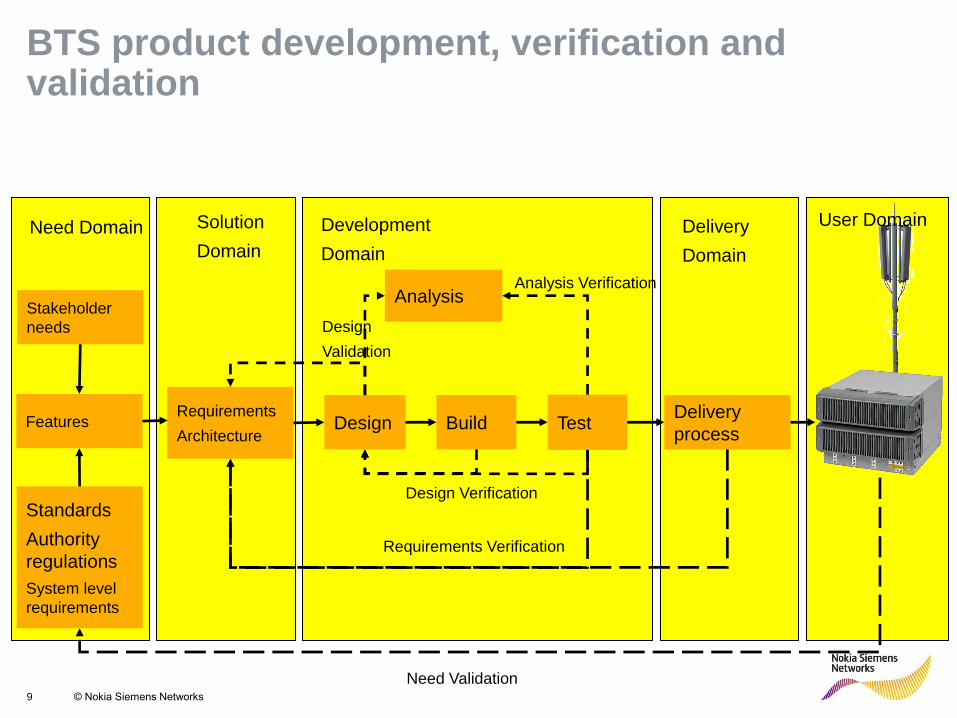
Build
Design Verification
Solution
Domain
Development
Domain
User Domain
Requirements
Architecture Design Test
Design
Validation
Analysis Analysis Verification
Requirements Verification
Stakeholder
needs
Features
Standards
Authority
regulations
System level
requirements
Need Domain
Delivery
process
Delivery
Domain
Need Validation
BTS product development, verification and validation

10 © Nokia Siemens Networks
R 255
G 211
B 8
R 255
G 175
B 0
R 127
G 16
B 162
R 163
G 166
B 173
R 137
G 146
B 155
R 175
G 0
B 51
R 52
G 195
B 51
R 0
G 0
B 0
R 255
G 255
B 255
Primary colours: Supporting colours:
Testability Over the Life-Cycle Testability properties
R&D Production Installation Use Field
Troubleshooting
Re-use of Embedded Tests over the Life-Cycle (Algorithms, HW-Structures, Software and Control Interface)
RFM
SM
Module and BTS
verification:
SWAPI
supported script
controlled test
functions (partly
BIST)
RFM
SM
Board and Module testing using
•POST, BIST,BIT BTS commissioning tests:
•Same as operator usable Field troubleshooting tools
BTS autonomous health check features:
•Supervision
•Alarm
•Self- diagnostics
•Self- recovery
R&D debug support:
•Tracing
•Monitoring
Operator BTS troubleshooting tools:
•RF loop test
•Ethernet test
•Antenna line Com
•EAC test
•RET exercise test
•Remote Self test
•Test models
HW service tools:
•Module BIST
R&D debugging tools
11 © Nokia Siemens Networks
R 255
G 211
B 8
R 255
G 175
B 0
R 127
G 16
B 162
R 163
G 166
B 173
R 137
G 146
B 155
R 175
G 0
B 51
R 52
G 195
B 51
R 0
G 0
B 0
R 255
G 255
B 255
Primary colours: Supporting colours:
Outline
Outline
Product under discussion
Stakeholders and their expectations
Test and design process
Requirements guiding the testability architecture design
Example of a test tool
Terms and abbreviations
12 © Nokia Siemens Networks
R 255
G 211
B 8
R 255
G 175
B 0
R 127
G 16
B 162
R 163
G 166
B 173
R 137
G 146
B 155
R 175
G 0
B 51
R 52
G 195
B 51
R 0
G 0
B 0
R 255
G 255
B 255
Primary colours: Supporting colours:
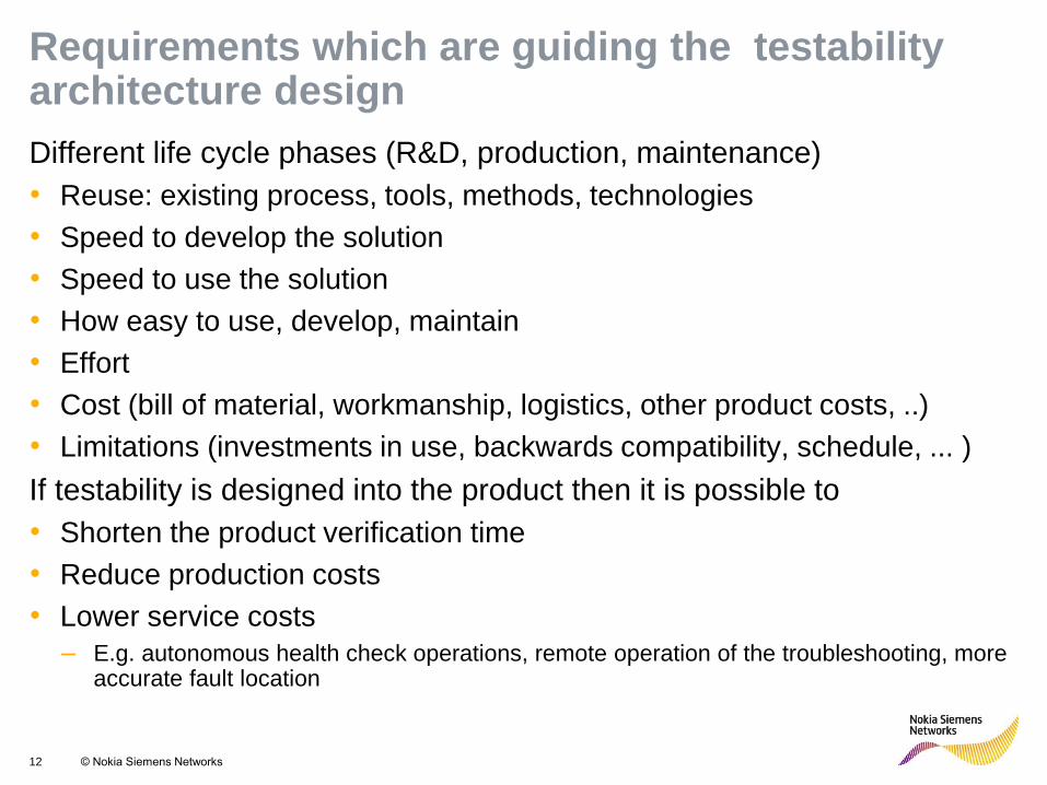
Requirements which are guiding the testability architecture design
Different life cycle phases (R&D, production, maintenance)
• Reuse: existing process, tools, methods, technologies
• Speed to develop the solution
• Speed to use the solution
• How easy to use, develop, maintain
• Effort
• Cost (bill of material, workmanship, logistics, other product costs, ..)
• Limitations (investments in use, backwards compatibility, schedule, ... )
If testability is designed into the product then it is possible to
• Shorten the product verification time
• Reduce production costs
• Lower service costs
– E.g. autonomous health check operations, remote operation of the troubleshooting, more accurate fault location
13 © Nokia Siemens Networks
R 255
G 211
B 8
R 255
G 175
B 0
R 127
G 16
B 162
R 163
G 166
B 173
R 137
G 146
B 155
R 175
G 0
B 51
R 52
G 195
B 51
R 0
G 0
B 0
R 255
G 255
B 255
Primary colours: Supporting colours:
Outline
Outline
Product under discussion
Stakeholders and their expectations
Test and design process
Requirements guiding the testability architecture design
Example of a test tool
Terms and abbreviations

14 © Nokia Siemens Networks
R 255
G 211
B 8
R 255
G 175
B 0
R 127
G 16
B 162
R 163
G 166
B 173
R 137
G 146
B 155
R 175
G 0
B 51
R 52
G 195
B 51
R 0
G 0
B 0
R 255
G 255
B 255
Primary colours: Supporting colours:
RF TEST LOOP
Example of a stakeholder need and how it was implemented
With RF test loop it is possible to test if RF signal path is functioning.
15 © Nokia Siemens Networks
R 255
G 211
B 8
R 255
G 175
B 0
R 127
G 16
B 162
R 163
G 166
B 173
R 137
G 146
B 155
R 175
G 0
B 51
R 52
G 195
B 51
R 0
G 0
B 0
R 255
G 255
B 255
Primary colours: Supporting colours:
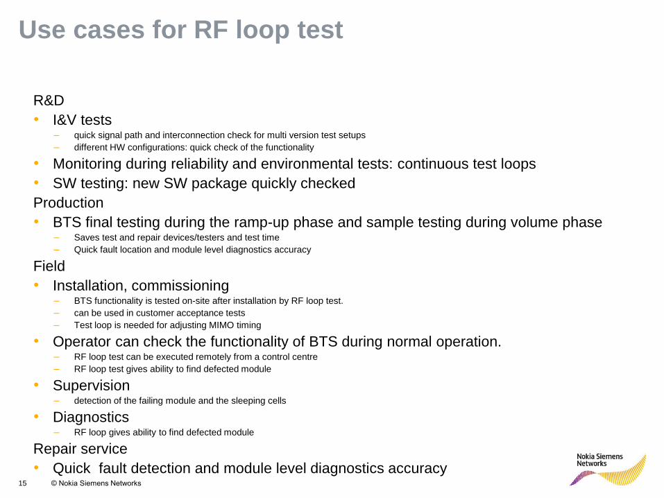
Use cases for RF loop test
R&D
• I&V tests – quick signal path and interconnection check for multi version test setups
– different HW configurations: quick check of the functionality
• Monitoring during reliability and environmental tests: continuous test loops
• SW testing: new SW package quickly checked
Production
• BTS final testing during the ramp-up phase and sample testing during volume phase – Saves test and repair devices/testers and test time
– Quick fault location and module level diagnostics accuracy
Field
• Installation, commissioning – BTS functionality is tested on-site after installation by RF loop test.
– can be used in customer acceptance tests
– Test loop is needed for adjusting MIMO timing
• Operator can check the functionality of BTS during normal operation. – RF loop test can be executed remotely from a control centre
– RF loop test gives ability to find defected module
• Supervision – detection of the failing module and the sleeping cells
• Diagnostics – RF loop gives ability to find defected module
Repair service
• Quick fault detection and module level diagnostics accuracy
16 © Nokia Siemens Networks
R 255
G 211
B 8
R 255
G 175
B 0
R 127
G 16
B 162
R 163
G 166
B 173
R 137
G 146
B 155
R 175
G 0
B 51
R 52
G 195
B 51
R 0
G 0
B 0
R 255
G 255
B 255
Primary colours: Supporting colours:
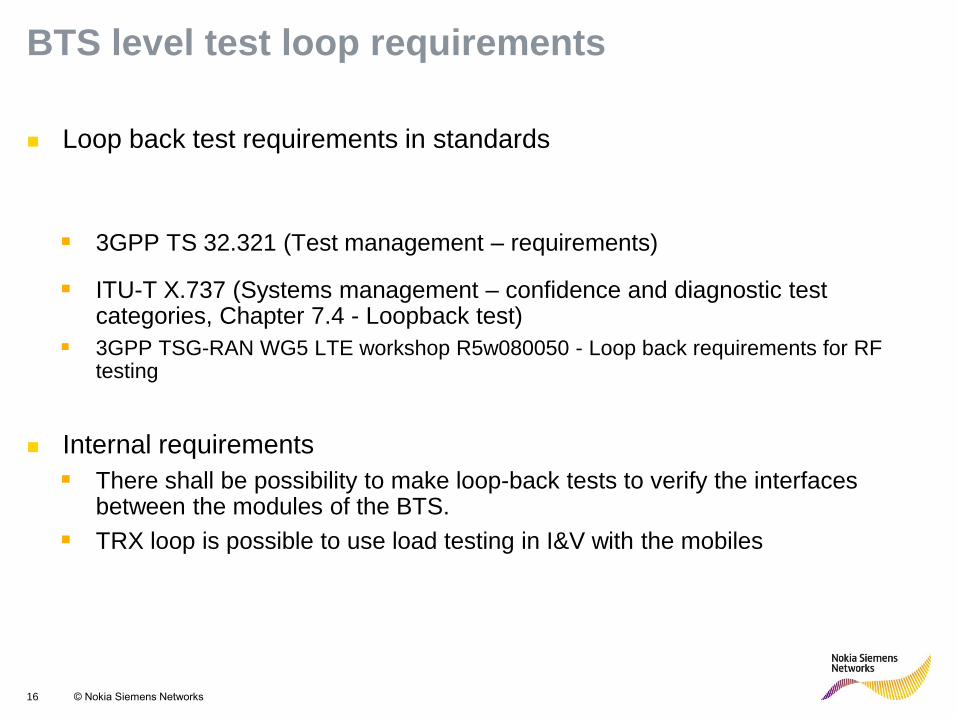
BTS level test loop requirements
Loop back test requirements in standards
3GPP TS 32.321 (Test management – requirements) ITU-T X.737 (Systems management – confidence and diagnostic test
categories, Chapter 7.4 - Loopback test)
3GPP TSG-RAN WG5 LTE workshop R5w080050 - Loop back requirements for RF testing
Internal requirements
There shall be possibility to make loop-back tests to verify the interfaces between the modules of the BTS.
TRX loop is possible to use load testing in I&V with the mobiles
17 © Nokia Siemens Networks
R 255
G 211
B 8
R 255
G 175
B 0
R 127
G 16
B 162
R 163
G 166
B 173
R 137
G 146
B 155
R 175
G 0
B 51
R 52
G 195
B 51
R 0
G 0
B 0
R 255
G 255
B 255
Primary colours: Supporting colours:
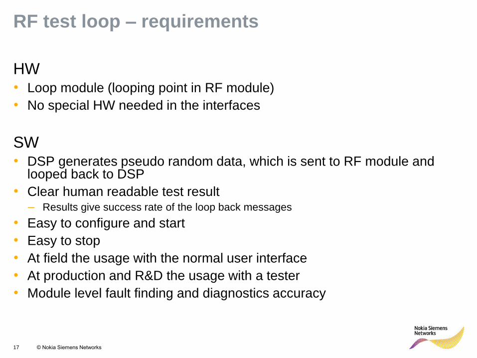
RF test loop – requirements
HW • Loop module (looping point in RF module)
• No special HW needed in the interfaces
SW • DSP generates pseudo random data, which is sent to RF module and
looped back to DSP
• Clear human readable test result – Results give success rate of the loop back messages
• Easy to configure and start
• Easy to stop
• At field the usage with the normal user interface
• At production and R&D the usage with a tester
• Module level fault finding and diagnostics accuracy
18 © Nokia Siemens Networks
R 255
G 211
B 8
R 255
G 175
B 0
R 127
G 16
B 162
R 163
G 166
B 173
R 137
G 146
B 155
R 175
G 0
B 51
R 52
G 195
B 51
R 0
G 0
B 0
R 255
G 255
B 255
Primary colours: Supporting colours:
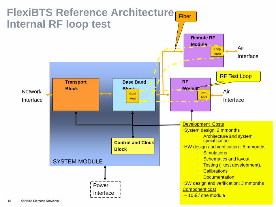
FlexiBTS Reference Architecture – Internal RF loop test
Transport
Block
Control and Clock
Block
Base Band
Block
Remote RF
Module Air
Interface
Power
Interface
Network
Interface
RF
Module Air
Interface
Loop
back
Loop
back
Gen/
Anal
RF Test Loop
Fiber
SYSTEM MODULE
Development Costs
•System design: 2 mmonths
• Architecture and system specification
•HW design and verification : 5 mmonths
• Simulations
• Schematics and layout
• Testing (+test development),
• Calibrations
• Documentation
•SW design and verification: 3 mmonths
Component cost
•~ 10 € / one module
19 © Nokia Siemens Networks
R 255
G 211
B 8
R 255
G 175
B 0
R 127
G 16
B 162
R 163
G 166
B 173
R 137
G 146
B 155
R 175
G 0
B 51
R 52
G 195
B 51
R 0
G 0
B 0
R 255
G 255
B 255
Primary colours: Supporting colours:
Outline
Outline
Product under discussion
Stakeholders and their expectations
Test and design process
Requirements guiding the testability architecture design
Example of a test tool
Terms and abbreviations
20 © Nokia Siemens Networks
R 255
G 211
B 8
R 255
G 175
B 0
R 127
G 16
B 162
R 163
G 166
B 173
R 137
G 146
B 155
R 175
G 0
B 51
R 52
G 195
B 51
R 0
G 0
B 0
R 255
G 255
B 255
Primary colours: Supporting colours:
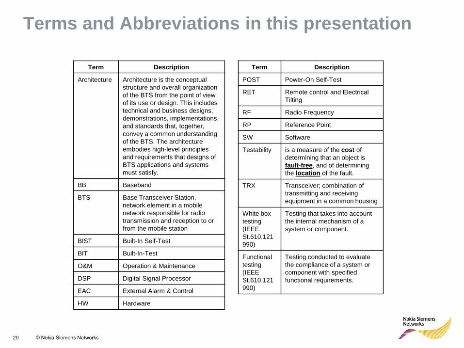
Terms and Abbreviations in this presentation
Term Description
Architecture
Architecture is the conceptual
structure and overall organization
of the BTS from the point of view
of its use or design. This includes
technical and business designs,
demonstrations, implementations,
and standards that, together,
convey a common understanding
of the BTS. The architecture
embodies high-level principles
and requirements that designs of
BTS applications and systems
must satisfy.
BB Baseband
BTS Base Transceiver Station,
network element in a mobile
network responsible for radio
transmission and reception to or
from the mobile station
BIST Built-In Self-Test
BIT Built-In-Test
O&M Operation & Maintenance
DSP Digital Signal Processor
EAC External Alarm & Control
HW Hardware
Term Description
POST Power-On Self-Test
RET Remote control and Electrical
Tilting
RF Radio Frequency
RP Reference Point
SW Software
Testability is a measure of the cost of
determining that an object is
fault-free, and of determining
the location of the fault.
TRX Transceiver; combination of
transmitting and receiving
equipment in a common housing
White box
testing
(IEEE
St.610.121
990)
Testing that takes into account
the internal mechanism of a
system or component.
Functional
testing
(IEEE
St.610.121
990)
Testing conducted to evaluate
the compliance of a system or
component with specified
functional requirements.