Embed Size (px)
DESCRIPTION
Frigidere Indesit - Manual Service
Citation preview
GB
All the parts included in this document are the property of Indesit Company S.p.A.
All rights reserved. This document and the information it contains are supplied without liability for possi-ble errors or omissions; no part of this document can be reproduced, used or copied without writtenpermission or without being authorised by the terms of a contract clause.
Service ManualNew Electronic Cold Platform 2005
Edition2005.03.25
LanguageEnglish
SERVICE MANUAL
New Electronic ColdPlatform 2005.
SERVICE MANUAL
New Electronic ColdPlatform 2005.
GB
2
Service ManualNew Electronic Cold Platform 2005
Edition2005.03.25
LanguageEnglish
CONTENTS OF THE MANUAL: NOTE FOR THE ENGINEERThis manual is a supporting document for technical personnel. It contains a description of the variousproduct types, the general operating principle, and indications concerning assistance.
Technical personnel should anyway consult the specific model on(www.servicenet.indesitcompany.com) to access data and updates of electrical diagrams, techni-cal bulletins, and spare parts.
GB
3
Service ManualNew Electronic Cold Platform 2005
Edition2005.03.25
LanguageEnglish
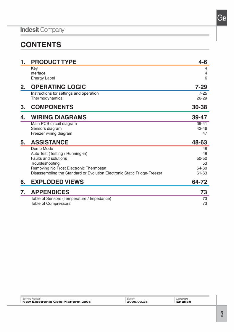
CONTENTS
1. PRODUCT TYPE 4-6Key 4nterface 4Energy Label 6
2. OPERATING LOGIC 7-29Instructions for settings and operation 7-25Thermodynamics 26-29
3. COMPONENTS 30-38
4. WIRING DIAGRAMS 39-47Main PCB circuit diagram 39-41Sensors diagram 42-46Freezer wiring diagram 47
5. ASSISTANCE 48-63Demo Mode 48Auto Test (Testing / Running-in) 48Faults and solutions 50-52Troubleshooting 53Removing No Frost Electronic Thermostat 54-60Disassembling the Standard or Evolution Electronic Static Fridge-Freezer 61-63
6. EXPLODED VIEWS 64-72
7. APPENDICES 73Table of Sensors (Temperature / Impedance) 73Table of Compressors 73
TY
PE
GB
4
Service ManualNew Electronic Cold Platform 2005
Edition2005.03.25
LanguageEnglish
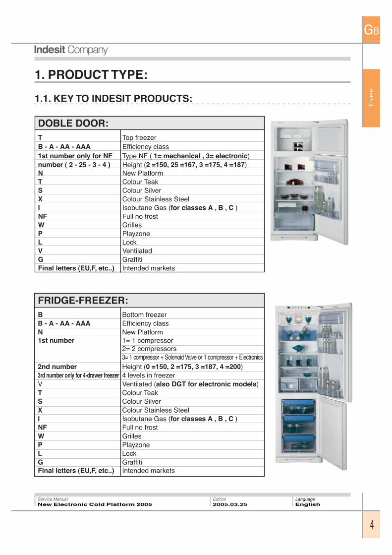
FRIDGE-FREEZER:B Bottom freezerB - A - AA - AAA Efficiency classN New Platform1st number 1= 1 compressor
2= 2 compressors3= 1 compressor + Solenoid Valve or 1 compressor + Electronics
2nd number Height (0 =150, 2 =175, 3 =187, 4 =200)3rd number only for 4-drawer freezer 4 levels in freezerV Ventilated (also DGT for electronic models)T Colour TeakS Colour SilverX Colour Stainless SteelI Isobutane Gas (for classes A , B , C )NF Full no frostW GrillesP PlayzoneL LockG GraffitiFinal letters (EU,F, etc..) Intended markets
1. PRODUCT TYPE:
1.1. KEY TO INDESIT PRODUCTS:
DOBLE DOOR:T Top freezerB - A - AA - AAA Efficiency class1st number only for NF Type NF ( 1= mechanical , 3= electronic)number ( 2 - 25 - 3 - 4 ) Height (2 =150, 25 =167, 3 =175, 4 =187)N New PlatformT Colour TeakS Colour SilverX Colour Stainless SteelI Isobutane Gas (for classes A , B , C )NF Full no frostW GrillesP PlayzoneL LockV VentilatedG GraffitiFinal letters (EU,F, etc..) Intended markets
TY
PE
GB
5
Service ManualNew Electronic Cold Platform 2005
Edition2005.03.25
LanguageEnglish
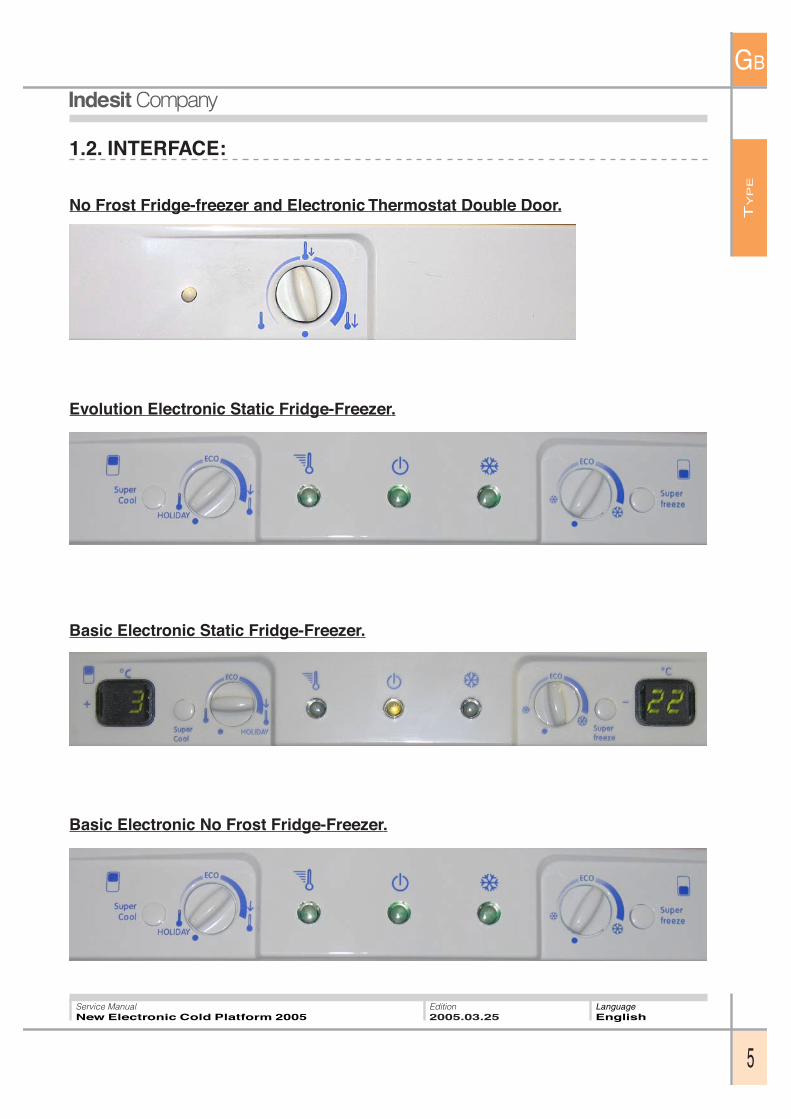
1.2. INTERFACE:
No Frost Fridge-freezer and Electronic Thermostat Double Door.
Basic Electronic Static Fridge-Freezer.
Evolution Electronic Static Fridge-Freezer.
Basic Electronic No Frost Fridge-Freezer.
TY
PE
GB
6
Service ManualNew Electronic Cold Platform 2005
Edition2005.03.25
LanguageEnglish
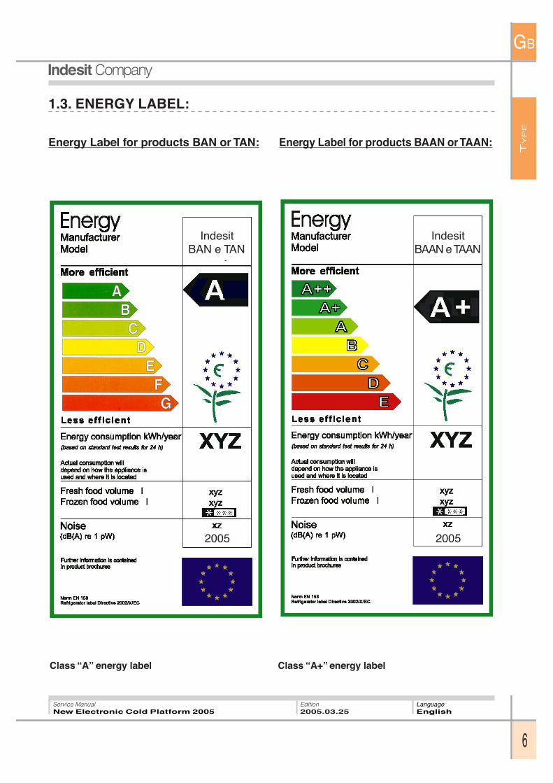
1.3. ENERGY LABEL:
Energy Label for products BAN or TAN:
Class “A” energy label
Energy Label for products BAAN or TAAN:
Class “A+” energy label
IndesitBAN e TAN
2005
IndesitBAAN e TAAN
2005
OP
ER
AT
ION
GB
7
Service ManualNew Electronic Cold Platform 2005
Edition2005.03.25
LanguageEnglish
2. PRODUCT TYPE:
NO FROST FRIDGE-FREEZER AND ELECTRONIC THERMOSTAT DOUBLE DOOR.
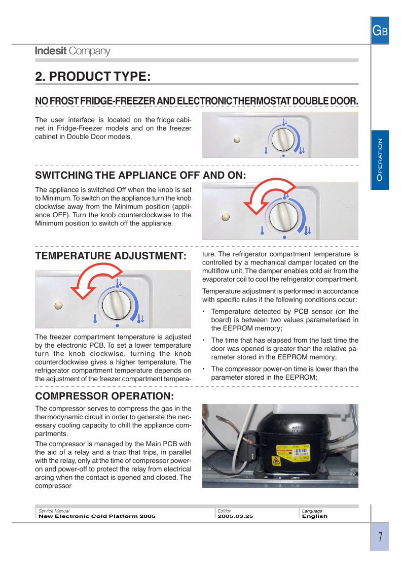
The user interface is located on the fridge cabi-net in Fridge-Freezer models and on the freezercabinet in Double Door models.
COMPRESSOR OPERATION:The compressor serves to compress the gas in thethermodynamic circuit in order to generate the nec-essary cooling capacity to chill the appliance com-partments.
The compressor is managed by the Main PCB withthe aid of a relay and a triac that trips, in parallelwith the relay, only at the time of compressor power-on and power-off to protect the relay from electricalarcing when the contact is opened and closed. Thecompressor
SWITCHING THE APPLIANCE OFF AND ON:The appliance is switched Off when the knob is setto Minimum. To switch on the appliance turn the knobclockwise away from the Minimum position (appli-ance OFF). Turn the knob counterclockwise to theMinimum position to switch off the appliance.
TEMPERATURE ADJUSTMENT: ture. The refrigerator compartment temperature iscontrolled by a mechanical damper located on themultiflow unit. The damper enables cold air from theevaporator coil to cool the refrigerator compartment.
Temperature adjustment is performed in accordancewith specific rules if the following conditions occur:
• Temperature detected by PCB sensor (on theboard) is between two values parameterised inthe EEPROM memory;
• The time that has elapsed from the last time thedoor was opened is greater than the relative pa-rameter stored in the EEPROM memory;
• The compressor power-on time is lower than theparameter stored in the EEPROM;
The freezer compartment temperature is adjustedby the electronic PCB. To set a lower temperatureturn the knob clockwise, turning the knobcounterclockwise gives a higher temperature. Therefrigerator compartment temperature depends onthe adjustment of the freezer compartment tempera-
OP
ER
AT
ION
GB
8
Service ManualNew Electronic Cold Platform 2005
Edition2005.03.25
LanguageEnglish
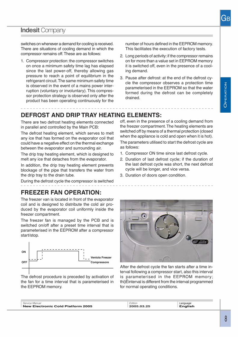
OFF
ON
Ventola Freezer
Compressore
FREEZER FAN OPERATION:The freezer van is located in front of the evaporatorcoil and is designed to distribute the cold air pro-duced by the evaporator coil uniformly inside thefreezer compartment.
The freezer fan is managed by the PCB and isswitched on/off after a preset time interval that isparameterised in the EEPROM after a compressorstart/stop.
The defrost procedure is preceded by activation ofthe fan for a time interval that is parameterised inthe EEPROM memory.
switches on whenever a demand for cooling is received.There are situations of cooling demand in which thecompressor remains off. These are as follows:
1. Compressor protection: the compressor switcheson once a minimum safety time lag has elapsedsince the last power-off, thereby allowing gaspressure to reach a point of equilibrium in therefrigerant circuit. The same minimum safety timeis observed in the event of a mains power inter-ruption (voluntary or involuntary). This compres-sor protection strategy is observed only after theproduct has been operating continuously for the
number of hours defined in the EEPROM memory.This facilitates the execution of factory tests.
2. Long periods of activity: if the compressor remainson for more than a value set in EEPROM memoryit is switched off, even in the presence of a cool-ing demand.
3. Pause after defrost: at the end of the defrost cy-cle the compressor observes a protection timeparameterised in the EEPROM so that the waterformed during the defrost can be completelydrained.
DEFROST AND DRIP TRAY HEATING ELEMENTS:There are two defrost heating elements connectedin parallel and controlled by the Main PCB:
The defrost heating element, which serves to meltany ice that has formed on the evaporator coil thatcould have a negative effect on the thermal exchangebetween the evaporator and surrounding air.
The drip tray heating element, which is designed tomelt any ice that detaches from the evaporator.
In addition, the drip tray heating element preventsblockage of the pipe that transfers the water fromthe drip tray to the drain tube.During the defrost cycle the compressor is switched
off, even in the presence of a cooling demand fromthe freezer compartment. The heating elements areswitched off by means of a thermal protection (closedwhen the appliance is cold and open when it is hot).
The parameters utilised to start the defrost cycle areas follows:
1. Compressor ON time since last defrost cycle.2. Duration of last defrost cycle; if the duration of
the last defrost cycle was short, the next defrostcycle will be longer, and vice versa.
3. Duration of doors open condition.
After the defrost cycle the fan starts after a time in-terval following a compressor start, also this intervalis parameter ised in the EEPROM memory;thi}Ëinterval is different from the interval programmedfor normal operating conditions.
OP
ER
AT
ION
GB
9
Service ManualNew Electronic Cold Platform 2005
Edition2005.03.25
LanguageEnglish
FRIDGE LAMP OPERATION:
FAULT MANAGEMENT:
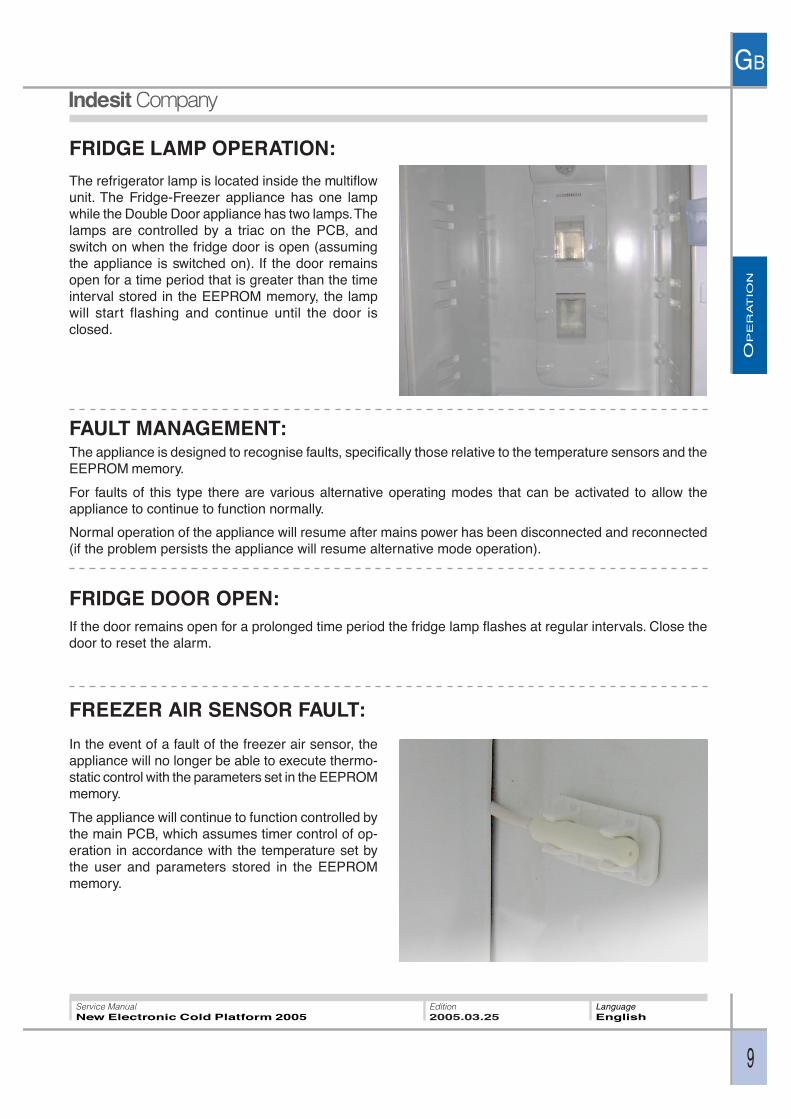
The refrigerator lamp is located inside the multiflowunit. The Fridge-Freezer appliance has one lampwhile the Double Door appliance has two lamps. Thelamps are controlled by a triac on the PCB, andswitch on when the fridge door is open (assumingthe appliance is switched on). If the door remainsopen for a time period that is greater than the timeinterval stored in the EEPROM memory, the lampwill start flashing and continue until the door isclosed.
The appliance is designed to recognise faults, specifically those relative to the temperature sensors and theEEPROM memory.
For faults of this type there are various alternative operating modes that can be activated to allow theappliance to continue to function normally.
Normal operation of the appliance will resume after mains power has been disconnected and reconnected(if the problem persists the appliance will resume alternative mode operation).
FRIDGE DOOR OPEN:If the door remains open for a prolonged time period the fridge lamp flashes at regular intervals. Close thedoor to reset the alarm.
FREEZER AIR SENSOR FAULT:
In the event of a fault of the freezer air sensor, theappliance will no longer be able to execute thermo-static control with the parameters set in the EEPROMmemory.
The appliance will continue to function controlled bythe main PCB, which assumes timer control of op-eration in accordance with the temperature set bythe user and parameters stored in the EEPROMmemory.
OP
ER
AT
ION
GB
10
Service ManualNew Electronic Cold Platform 2005
Edition2005.03.25
LanguageEnglish
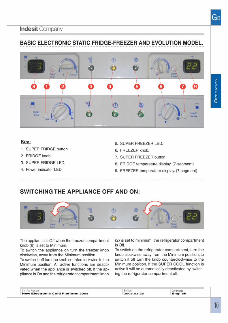
BASIC ELECTRONIC STATIC FRIDGE-FREEZER AND EVOLUTION MODEL.
Key:
1. SUPER FRIDGE button.
2. FRIDGE knob.
3. SUPER FRIDGE LED.
4. Power indicator LED.
5. SUPER FREEZER LED.
6. FREEZER knob.
7. SUPER FREEZER button.
8. FRIDGE temperature display. (7-segment)
9. FREEZER temperature display. (7-segment)
SWITCHING THE APPLIANCE OFF AND ON:
The appliance is Off when the freezer compartmentknob (6) is set to Minimum.To switch the appliance on turn the freezer knobclockwise, away from the Minimum position.To switch it off turn the knob counterclockwise to theMinimum position. All active functions are deacti-vated when the appliance is switched off. If the ap-pliance is On and the refrigerator compartment knob
(2) is set to minimum, the refrigerator compartmentis Off.To switch on the refrigerator compartment, turn theknob clockwise away from the Minimum position; toswitch it off turn the knob counterclockwise to theMinimum position. If the SUPER COOL function isactive it will be automatically deactivated by switch-ing the refrigerator compartment off.
1 2 3 4 5 6 78 9
OP
ER
AT
ION
GB
11
Service ManualNew Electronic Cold Platform 2005
Edition2005.03.25
LanguageEnglish
TEMPERATURE SETTING:
Turn the refrigerator knob (2) or freezer knob (6)clockwise to decrease the temperature orcounterclockwise to increase the temperature untilreaching the minimum position; when the refrigera-
tor knob is set to minimum the refrigerator compart-ment will be switched off, while setting the freezerknob to minimum switches off the entire appliance.
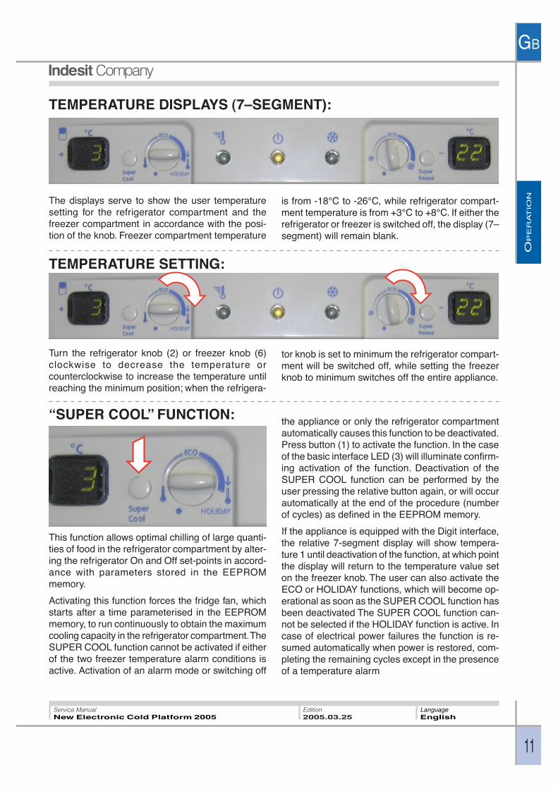
“SUPER COOL” FUNCTION:
TEMPERATURE DISPLAYS (7–SEGMENT):
The displays serve to show the user temperaturesetting for the refrigerator compartment and thefreezer compartment in accordance with the posi-tion of the knob. Freezer compartment temperature
is from -18°C to -26°C, while refrigerator compart-ment temperature is from +3°C to +8°C. If either therefrigerator or freezer is switched off, the display (7–segment) will remain blank.
This function allows optimal chilling of large quanti-ties of food in the refrigerator compartment by alter-ing the refrigerator On and Off set-points in accord-ance with parameters stored in the EEPROMmemory.
Activating this function forces the fridge fan, whichstarts after a time parameterised in the EEPROMmemory, to run continuously to obtain the maximumcooling capacity in the refrigerator compartment. TheSUPER COOL function cannot be activated if eitherof the two freezer temperature alarm conditions isactive. Activation of an alarm mode or switching off
the appliance or only the refrigerator compartmentautomatically causes this function to be deactivated.Press button (1) to activate the function. In the caseof the basic interface LED (3) will illuminate confirm-ing activation of the function. Deactivation of theSUPER COOL function can be performed by theuser pressing the relative button again, or will occurautomatically at the end of the procedure (numberof cycles) as defined in the EEPROM memory.
If the appliance is equipped with the Digit interface,the relative 7-segment display will show tempera-ture 1 until deactivation of the function, at which pointthe display will return to the temperature value seton the freezer knob. The user can also activate theECO or HOLIDAY functions, which will become op-erational as soon as the SUPER COOL function hasbeen deactivated The SUPER COOL function can-not be selected if the HOLIDAY function is active. Incase of electrical power failures the function is re-sumed automatically when power is restored, com-pleting the remaining cycles except in the presenceof a temperature alarm
OP
ER
AT
ION
GB
12
Service ManualNew Electronic Cold Platform 2005
Edition2005.03.25
LanguageEnglish
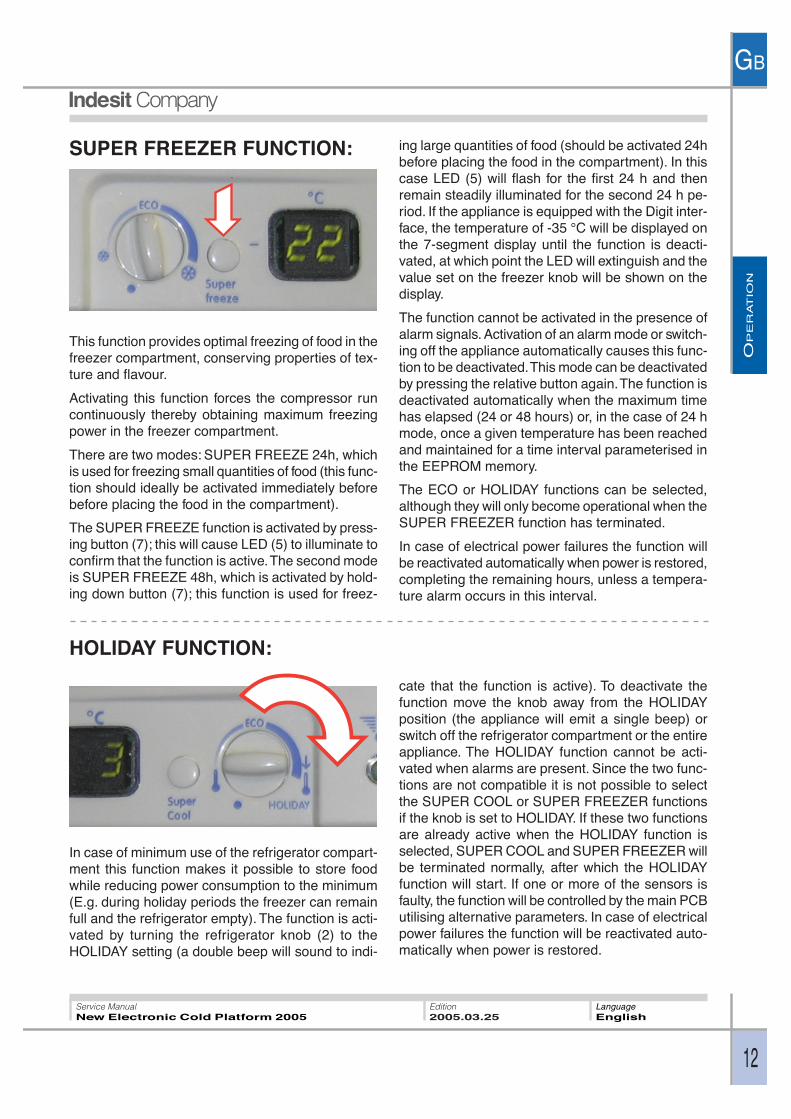
This function provides optimal freezing of food in thefreezer compartment, conserving properties of tex-ture and flavour.
Activating this function forces the compressor runcontinuously thereby obtaining maximum freezingpower in the freezer compartment.
There are two modes: SUPER FREEZE 24h, whichis used for freezing small quantities of food (this func-tion should ideally be activated immediately beforebefore placing the food in the compartment).
The SUPER FREEZE function is activated by press-ing button (7); this will cause LED (5) to illuminate toconfirm that the function is active. The second modeis SUPER FREEZE 48h, which is activated by hold-ing down button (7); this function is used for freez-
ing large quantities of food (should be activated 24hbefore placing the food in the compartment). In thiscase LED (5) will flash for the first 24 h and thenremain steadily illuminated for the second 24 h pe-riod. If the appliance is equipped with the Digit inter-face, the temperature of -35 °C will be displayed onthe 7-segment display until the function is deacti-vated, at which point the LED will extinguish and thevalue set on the freezer knob will be shown on thedisplay.
The function cannot be activated in the presence ofalarm signals. Activation of an alarm mode or switch-ing off the appliance automatically causes this func-tion to be deactivated. This mode can be deactivatedby pressing the relative button again. The function isdeactivated automatically when the maximum timehas elapsed (24 or 48 hours) or, in the case of 24 hmode, once a given temperature has been reachedand maintained for a time interval parameterised inthe EEPROM memory.
The ECO or HOLIDAY functions can be selected,although they will only become operational when theSUPER FREEZER function has terminated.
In case of electrical power failures the function willbe reactivated automatically when power is restored,completing the remaining hours, unless a tempera-ture alarm occurs in this interval.
SUPER FREEZER FUNCTION:
HOLIDAY FUNCTION:
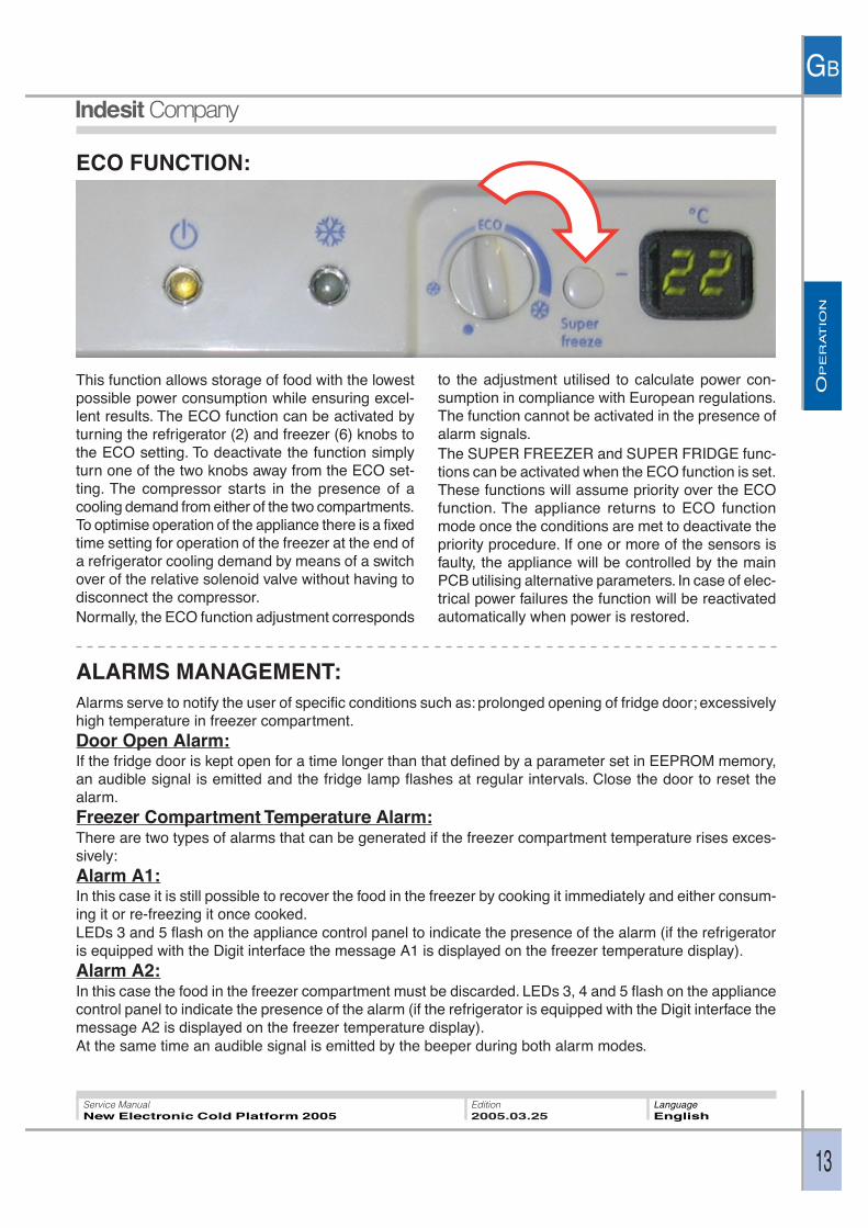
In case of minimum use of the refrigerator compart-ment this function makes it possible to store foodwhile reducing power consumption to the minimum(E.g. during holiday periods the freezer can remainfull and the refrigerator empty). The function is acti-vated by turning the refrigerator knob (2) to theHOLIDAY setting (a double beep will sound to indi-
cate that the function is active). To deactivate thefunction move the knob away from the HOLIDAYposition (the appliance will emit a single beep) orswitch off the refrigerator compartment or the entireappliance. The HOLIDAY function cannot be acti-vated when alarms are present. Since the two func-tions are not compatible it is not possible to selectthe SUPER COOL or SUPER FREEZER functionsif the knob is set to HOLIDAY. If these two functionsare already active when the HOLIDAY function isselected, SUPER COOL and SUPER FREEZER willbe terminated normally, after which the HOLIDAYfunction will start. If one or more of the sensors isfaulty, the function will be controlled by the main PCButilising alternative parameters. In case of electricalpower failures the function will be reactivated auto-matically when power is restored.
OP
ER
AT
ION
GB
13
Service ManualNew Electronic Cold Platform 2005
Edition2005.03.25
LanguageEnglish
ECO FUNCTION:
ALARMS MANAGEMENT:Alarms serve to notify the user of specific conditions such as: prolonged opening of fridge door; excessivelyhigh temperature in freezer compartment.Door Open Alarm:If the fridge door is kept open for a time longer than that defined by a parameter set in EEPROM memory,an audible signal is emitted and the fridge lamp flashes at regular intervals. Close the door to reset thealarm.Freezer Compartment Temperature Alarm:There are two types of alarms that can be generated if the freezer compartment temperature rises exces-sively:Alarm A1:In this case it is still possible to recover the food in the freezer by cooking it immediately and either consum-ing it or re-freezing it once cooked.LEDs 3 and 5 flash on the appliance control panel to indicate the presence of the alarm (if the refrigeratoris equipped with the Digit interface the message A1 is displayed on the freezer temperature display).Alarm A2:In this case the food in the freezer compartment must be discarded. LEDs 3, 4 and 5 flash on the appliancecontrol panel to indicate the presence of the alarm (if the refrigerator is equipped with the Digit interface themessage A2 is displayed on the freezer temperature display).At the same time an audible signal is emitted by the beeper during both alarm modes.
This function allows storage of food with the lowestpossible power consumption while ensuring excel-lent results. The ECO function can be activated byturning the refrigerator (2) and freezer (6) knobs tothe ECO setting. To deactivate the function simplyturn one of the two knobs away from the ECO set-ting. The compressor starts in the presence of acooling demand from either of the two compartments.To optimise operation of the appliance there is a fixedtime setting for operation of the freezer at the end ofa refrigerator cooling demand by means of a switchover of the relative solenoid valve without having todisconnect the compressor.Normally, the ECO function adjustment corresponds
to the adjustment utilised to calculate power con-sumption in compliance with European regulations.The function cannot be activated in the presence ofalarm signals.The SUPER FREEZER and SUPER FRIDGE func-tions can be activated when the ECO function is set.These functions will assume priority over the ECOfunction. The appliance returns to ECO functionmode once the conditions are met to deactivate thepriority procedure. If one or more of the sensors isfaulty, the appliance will be controlled by the mainPCB utilising alternative parameters. In case of elec-trical power failures the function will be reactivatedautomatically when power is restored.

OP
ER
AT
ION
GB
14
Service ManualNew Electronic Cold Platform 2005
Edition2005.03.25
LanguageEnglish
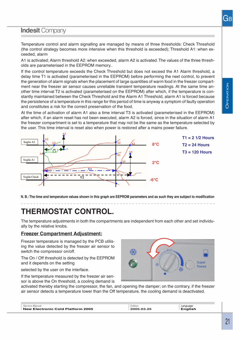
In alarm status the appliance forces operation utilising specific On / Off parameters that control the tem-perature in the freezer compartment at specific values depending on the type of alarm. To reset the alarmand restore normal operation, the appliance must be set to LOGICAL OFF (freezer knob set to minimum).Control of freezer compartment temperature is continuous during operation of the appliance, by means ofthe freezer air temperature sensor; this control will proceed even if the appliance is in one of the twoavailable alarm conditions. In the event of a freezer air sensor fault, the alarms will no longer be displayed.Temperature control is not performed for a time parameterised in the EEPROM memory to prevent falsealarms both during the testing process and at the time of power-on immediately after the appliance hasbeen purchased.Temperature control and alarm signalling are managed by means of three thresholds: Check Threshold(the control strategy becomes more intensive when this threshold is exceeded); Threshold A1: when ex-ceeded, alarm A1 is activated; Threshold A2: when exceeded, alarm A2 is activated. The values of the threethresholds are parameterised in the EEPROM memory.If the control temperature exceeds the Check Threshold but does not exceed the A1 Alarm threshold, adelay time T1 is activated (parameterised in the EEPROM) before performing the next control, to preventthe generation of alarm signals when the placement of large quantities of warm food in the freezer compart-ment near the freezer air sensor causes unreliable transient temperature readings. At the same time an-other time interval T2 is activated (parameterised on the EEPROM) after which, if the temperature is con-stantly maintained between the Check Threshold and the Alarm A1 Threshold, alarm A1 is forced becausethe persistence of a temperature in this range for this period of time is anyway a symptom of faulty operationand constitutes a risk for the correct preservation of the food.At the time of activation of alarm A1 also a time interval T3 is activated (parameterised in the EEPROM)after which, if an alarm reset has not been executed, alarm A2 is forced, since in the situation of alarm A1the freezer compartment is set to a temperature that may not be the same as the temperature selected bythe user. This time interval is reset also when power is restored after a mains power failure.
THERMOSTAT CONTROL.The temperature adjustments in both the compartments are independent from each other and set individu-ally by the relative knobs.
Freezer Compartment Adjustment:
8°C
-6°C
2°C
T1 = 2 1/2 Hours
T2 = 24 Hours
T1 = 120 Hours
N. B.: The time and temperature values shown in this graph are EEPROM parameters and as such they are subject to modification
Freezer temperature is managed by the PCB utilisingthe value detected by the freezer air sensor to switchthe compressor on/off.The On / Off threshold is detected by the EEPROMand it depends on the user setting.on the interface.
OP
ER
AT
ION
GB
15
Service ManualNew Electronic Cold Platform 2005
Edition2005.03.25
LanguageEnglish
Compressor Operation:
The compressor serves to compress the gas in thethermodynamic circuit in order to generate the nec-essary cooling capacity to chill the appliance com-partments.The compressor is managed by the Main PCB withthe aid of a relay and a triac that trips, in parallel withthe relay, only at the time of compressor power-onand power-off to protect the relay from electrical arc-ing when the contact is opened and closed, other-wise the compressor is powered exclusively via therelay when it is running.The compressor is started whenever a cooling de-mand is received.In certain conditions the compressor will remain stopped despite the presence cooling demands; thesesituations are as follows:
Compressor protection:
The compressor switches on once a minimum safety time interval (parameterised in the EEPROM) haselapsed since the last power off, thereby allowing the pressure of gas to reach a point of equilibrium in therefrigerant circuit. The same minimum safety time is observed in the event of a mains power interruption(voluntary or involuntary). This compressor protection strategy is observed only after the product has beenoperating continuously for a number of hours defined in the memory. This facilitates the execution of factorytests.
Long periods of activity:
If the compressor runs for a time greater than a value defined in the EEPROM memory, it is switched offeven in the presence of a cooling demand from either or both compartments. This feature is designed toprotect the compressor.
Fridge Fan Operation: (only in Digit models)
The fan is designed to distribute cold air uniformly inside the fridge compartment. The fan is controlled by
If the temperature measured by the freezer air sensor is above the On threshold a cooling demand isactivated thereby starting the compressor; on the contrary, if the freezer air sensor detects a temperaturelower than the Off temperature, the cooling demand is deactivated.
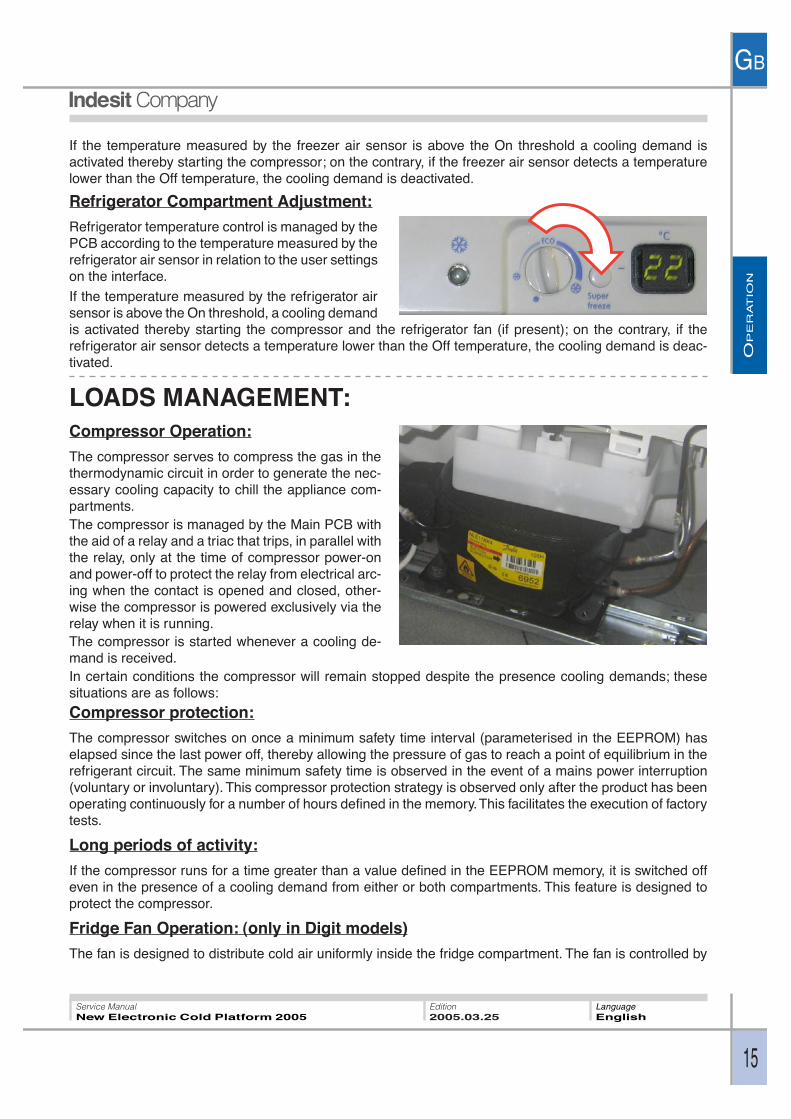
Refrigerator Compartment Adjustment:
Refrigerator temperature control is managed by thePCB according to the temperature measured by therefrigerator air sensor in relation to the user settingson the interface.
If the temperature measured by the refrigerator airsensor is above the On threshold, a cooling demandis activated thereby starting the compressor and the refrigerator fan (if present); on the contrary, if therefrigerator air sensor detects a temperature lower than the Off temperature, the cooling demand is deac-tivated.
LOADS MANAGEMENT:
OP
ER
AT
ION
GB
16
Service ManualNew Electronic Cold Platform 2005
Edition2005.03.25
LanguageEnglish
the PCB and it starts on receipt of a refrigerator compartment cooling demand after a time intervalparameterised in the EEPROM following start-up of the compressor.
It may occur that the fan is kept switched off, even though the compressor is running.
This occurs in the event that the fridge door is open.
In order to check that the refrigerator fan is functioning correctly “door closed” conditions must be simulatedby applying a magnet.
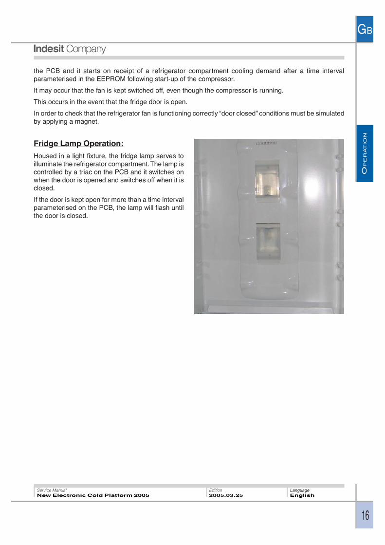
Fridge Lamp Operation:
Housed in a light fixture, the fridge lamp serves toilluminate the refrigerator compartment. The lamp iscontrolled by a triac on the PCB and it switches onwhen the door is opened and switches off when it isclosed.
If the door is kept open for more than a time intervalparameterised on the PCB, the lamp will flash untilthe door is closed.
OP
ER
AT
ION
GB
17
Service ManualNew Electronic Cold Platform 2005
Edition2005.03.25
LanguageEnglish
1 2 3 4 5 6 7
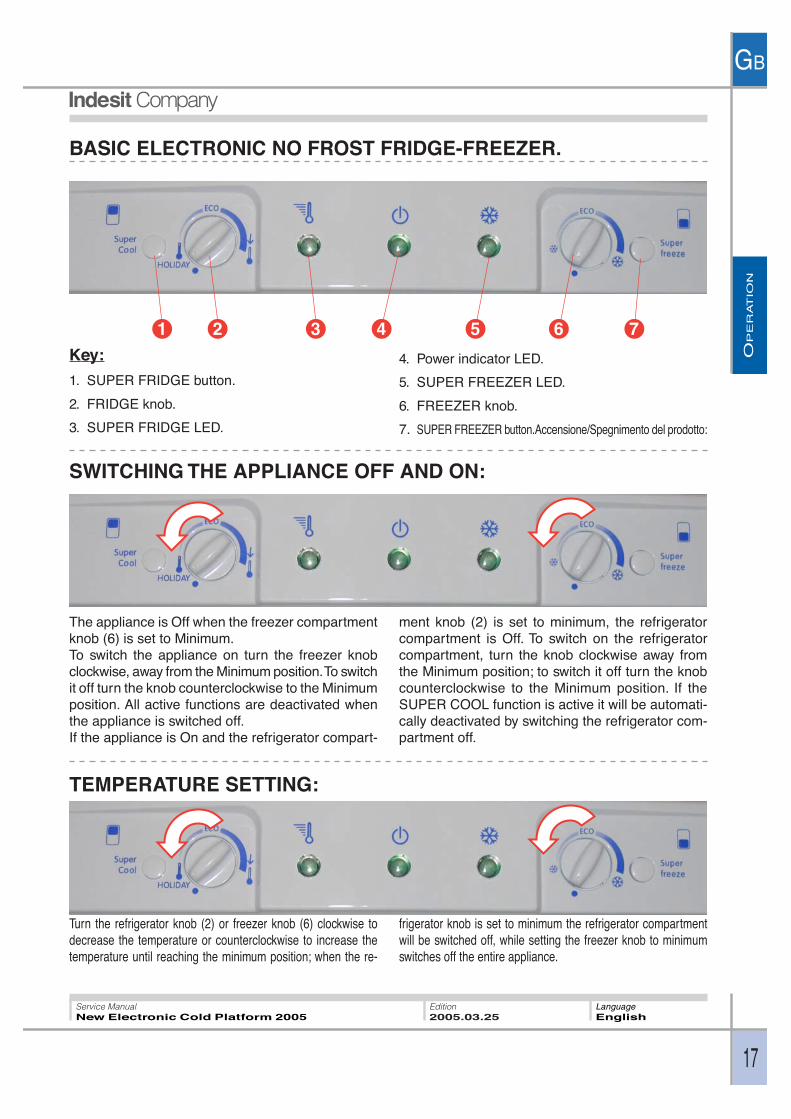
BASIC ELECTRONIC NO FROST FRIDGE-FREEZER.
Key:
1. SUPER FRIDGE button.
2. FRIDGE knob.
3. SUPER FRIDGE LED.
4. Power indicator LED.
5. SUPER FREEZER LED.
6. FREEZER knob.
7. SUPER FREEZER button.Accensione/Spegnimento del prodotto:
SWITCHING THE APPLIANCE OFF AND ON:
TEMPERATURE SETTING:
Turn the refrigerator knob (2) or freezer knob (6) clockwise todecrease the temperature or counterclockwise to increase thetemperature until reaching the minimum position; when the re-
frigerator knob is set to minimum the refrigerator compartmentwill be switched off, while setting the freezer knob to minimumswitches off the entire appliance.
The appliance is Off when the freezer compartmentknob (6) is set to Minimum.To switch the appliance on turn the freezer knobclockwise, away from the Minimum position. To switchit off turn the knob counterclockwise to the Minimumposition. All active functions are deactivated whenthe appliance is switched off.If the appliance is On and the refrigerator compart-
ment knob (2) is set to minimum, the refrigeratorcompartment is Off. To switch on the refrigeratorcompartment, turn the knob clockwise away fromthe Minimum position; to switch it off turn the knobcounterclockwise to the Minimum position. If theSUPER COOL function is active it will be automati-cally deactivated by switching the refrigerator com-partment off.
OP
ER
AT
ION
GB
18
Service ManualNew Electronic Cold Platform 2005
Edition2005.03.25
LanguageEnglish
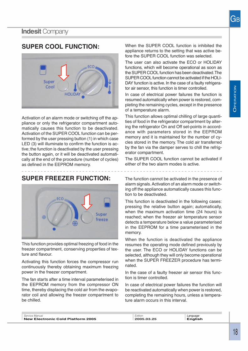
SUPER FREEZER FUNCTION:
This function provides optimal freezing of food in thefreezer compartment, conserving properties of tex-ture and flavour.
Activating this function forces the compressor runcontinuously thereby obtaining maximum freezingpower in the freezer compartment.
The fan starts after a time interval parameterised inthe EEPROM memory from the compressor ONtime, thereby displacing the cold air from the evapo-rator coil and allowing the freezer compartment tobe chilled.
The function cannot be activated in the presence ofalarm signals. Activation of an alarm mode or switch-ing off the appliance automatically causes this func-tion to be deactivated.
This function is deactivated in the following cases:pressing the relative button again; automatically,when the maximum activation time (24 hours) isreached; when the freezer air temperature sensordetects a temperature below a value parameterisedin the EEPROM for a time parameterised in thememory.
When the function is deactivated the applianceresumes the operating mode defined previously bythe user. The ECO or HOLIDAY functions can beselected, although they will only become operationalwhen the SUPER FREEZER procedure has termi-nated.
In the case of a faulty freezer air sensor this func-tion is timer controlled.
In case of electrical power failures the function willbe reactivated automatically when power is restored,completing the remaining hours, unless a tempera-ture alarm occurs in this interval.
SUPER COOL FUNCTION: When the SUPER COOL function is inhibited theappliance returns to the setting that was active be-fore the SUPER COOL function was selected.
The user can also activate the ECO or HOLIDAYfunctions, which will become operational as soon asthe SUPER COOL function has been deactivated. TheSUPER COOL function cannot be activated if the HOLI-DAY function is active. In the case of a faulty refrigera-tor air sensor, this function is timer controlled.
In case of electrical power failures the function isresumed automatically when power is restored, com-pleting the remaining cycles, except in the presenceof a temperature alarm.
This function allows optimal chilling of large quanti-ties of food in the refrigerator compartment by alter-ing the refrigerator On and Off set-points in accord-ance with parameters stored in the EEPROMmemory and it is maintained for the number of cy-cles stored in the memory. The cold air transferredby the fan via the damper serves to chill the refrig-erator compartment.
The SUPER COOL function cannot be activated ifeither of the two alarm modes is active.
Activation of an alarm mode or switching off the ap-pliance or only the refrigerator compartment auto-matically causes this function to be deactivated.Activation of the SUPER COOL function can be per-formed by the user pressing button (1) in which caseLED (3) will illuminate to confirm the function is ac-tive; the function is deactivated by the user pressingthe button again, or it will be deactivated automati-cally at the end of the procedure (number of cycles)as defined in the EEPROM memory.
OP
ER
AT
ION
GB
19
Service ManualNew Electronic Cold Platform 2005
Edition2005.03.25
LanguageEnglish
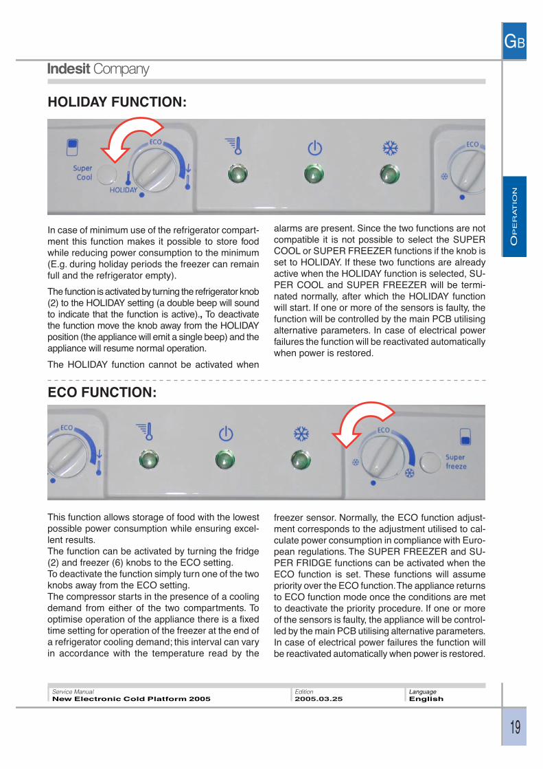
HOLIDAY FUNCTION:
alarms are present. Since the two functions are notcompatible it is not possible to select the SUPERCOOL or SUPER FREEZER functions if the knob isset to HOLIDAY. If these two functions are alreadyactive when the HOLIDAY function is selected, SU-PER COOL and SUPER FREEZER will be termi-nated normally, after which the HOLIDAY functionwill start. If one or more of the sensors is faulty, thefunction will be controlled by the main PCB utilisingalternative parameters. In case of electrical powerfailures the function will be reactivated automaticallywhen power is restored.
In case of minimum use of the refrigerator compart-ment this function makes it possible to store foodwhile reducing power consumption to the minimum(E.g. during holiday periods the freezer can remainfull and the refrigerator empty).
The function is activated by turning the refrigerator knob(2) to the HOLIDAY setting (a double beep will soundto indicate that the function is active)., To deactivatethe function move the knob away from the HOLIDAYposition (the appliance will emit a single beep) and theappliance will resume normal operation.
The HOLIDAY function cannot be activated when
ECO FUNCTION:
This function allows storage of food with the lowestpossible power consumption while ensuring excel-lent results.The function can be activated by turning the fridge(2) and freezer (6) knobs to the ECO setting.To deactivate the function simply turn one of the twoknobs away from the ECO setting.The compressor starts in the presence of a coolingdemand from either of the two compartments. Tooptimise operation of the appliance there is a fixedtime setting for operation of the freezer at the end ofa refrigerator cooling demand; this interval can varyin accordance with the temperature read by the
freezer sensor. Normally, the ECO function adjust-ment corresponds to the adjustment utilised to cal-culate power consumption in compliance with Euro-pean regulations. The SUPER FREEZER and SU-PER FRIDGE functions can be activated when theECO function is set. These functions will assumepriority over the ECO function. The appliance returnsto ECO function mode once the conditions are metto deactivate the priority procedure. If one or moreof the sensors is faulty, the appliance will be control-led by the main PCB utilising alternative parameters.In case of electrical power failures the function willbe reactivated automatically when power is restored.
OP
ER
AT
ION
GB
20
Service ManualNew Electronic Cold Platform 2005
Edition2005.03.25
LanguageEnglish
ALARMS MANAGEMENT:Alarms serve to notify the user of specific conditions such as: prolonged opening of fridge door; excessivetemperature in freezer compartment.
Door Open Alarm:
If the fridge door is kept open for a time longer than that defined by a parameter set in EEPROM memory,an audible signal is emitted and the fridge lamp flashes at regular intervals. Close the door to reset thealarm.
Freezer Compartment Temperature Alarm:
There are two types of alarms that can be generated if the freezer compartment temperature rises exces-sively:
Alarm A1:
In this case it is still possible to recover the food in the freezer by cooking it immediately and either consum-ing it or re-freezing it once cooked. LEDs 3 and 5 flash on the appliance control panel to indicate thepresence of the alarm, while a beeper signal is emitted at the same time.
Alarm A2:
In this case the food in the freezer compartment must be discarded. LEDs 3, 4 and 5 flash on the appliancecontrol panel to indicate the presence of the alarm, while a beeper signal is emitted at the same time.
In alarm status the appliance inhibits all functions or adjustments to force a specific operating mode withspecific On/ Off thresholds that set the freezer compartment temperature to given values in relation to thetype of alarm (A1 or A2); the new On / Off thresholds for the two alarm types are parameterised in theEEPROM memory. During alarm status forced defrost cycles are executed, activated once the number ofhours parameterised in the EEPROM memory have elapsed, as in normal operation. To reset the alarm andrestore normal operation, the appliance must be set to LOGICAL OFF (freezer knob set to minimum).
The beeper can be muted by opening and closing the refrigerator door. When alarm status is reset thetimer-controlled defrost cycles are deactivated, but if the alarm reset occurs during a defrost cycle, thealarm is reset but the current defrost cycle continues to its natural conclusion. If the appliance is set tological OFF with A1 or A2 active, and then switched on again after a fixed number of minutes as parameterisedin the EEPROM memory, a defrost cycle is forced after which the appliance will resume operation in ac-cordance with the settings that were present before the alarm.
Once the appliance has entered alarm status it is not possible to quit except by means of a reset procedure(the only possible change is the transition from alarm A1 to alarm A2). In the event of a power failure, thestate present at the time of interruption is resumed when power is restored.
Control of freezer compartment temperature, performed by means of the freezer air temperature sensor, isexecuted continuously during appliance operation. In the event of a freezer air sensor fault, the alarms willno longer be displayed.
Temperature control does not start for a time parameterised in the EEPROM memory from the first power-on of the appliance, thus avoiding the possible occurrence of alarms during the testing phases at the firstpower-on at the user’s home.
When the appliance is ON, the temperature control is inhibited for a given time interval parameterised in theEEPROM memory in order to give the compartment time to cool without generating any superfluous alarms.
After a mains power failure the freezer compartment temperature is checked immediately, since prolongedabsence of electrical power is the main cause for heating of the appliance.
OP
ER
AT
ION
GB
21
Service ManualNew Electronic Cold Platform 2005
Edition2005.03.25
LanguageEnglish
8°C
-6°C
2°C
Temperature control and alarm signalling are managed by means of three thresholds: Check Threshold(the control strategy becomes more intensive when this threshold is exceeded); Threshold A1: when ex-ceeded, alarm
A1 is activated; Alarm threshold A2: when exceeded, alarm A2 is activated. The values of the three thresh-olds are parameterised in the EEPROM memory..
If the control temperature exceeds the Check Threshold but does not exceed the A1 Alarm threshold, adelay time T1 is activated (parameterised in the EEPROM) before performing the next control, to preventthe generation of alarm signals when the placement of large quantities of warm food in the freezer compart-ment near the freezer air sensor causes unreliable transient temperature readings. At the same time an-other time interval T2 is activated (parameterised on the EEPROM) after which, if the temperature is con-stantly maintained between the Check Threshold and the Alarm A1 Threshold, alarm A1 is forced becausethe persistence of a temperature in this range for this period of time is anyway a symptom of faulty operationand constitutes a risk for the correct preservation of the food.
At the time of activation of alarm A1 also a time interval T3 is activated (parameterised in the EEPROM)after which, if an alarm reset has not been executed, alarm A2 is forced, since in the situation of alarm A1the freezer compartment is set to a temperature that may not be the same as the temperature selected bythe user. This time interval is reset also when power is restored after a mains power failure.
THERMOSTAT CONTROL.The temperature adjustments in both the compartments are independent from each other and set individu-ally by the relative knobs.
Freezer Compartment Adjustment:
Freezer temperature is managed by the PCB utilis-ing the value detected by the freezer air sensor toswitch the compressor on/off.
The On / Off threshold is detected by the EEPROMand it depends on the setting
selected by the user on the interface.
If the temperature measured by the freezer air sen-sor is above the On threshold, a cooling demand isactivated thereby starting the compressor, the fan, and opening the damper; on the contrary, if the freezerair sensor detects a temperature lower than the Off temperature, the cooling demand is deactivated.
T1 = 2 1/2 Hours
T2 = 24 Hours
T3 = 120 Hours
N. B.: The time and temperature values shown in this graph are EEPROM parameters and as such they are subject to modification

OP
ER
AT
ION
GB
22
Service ManualNew Electronic Cold Platform 2005
Edition2005.03.25
LanguageEnglish
Refrigerator Compartment Adjustment:
Refrigerator temperature control is managed by thePCB according to the temperature measured by therefrigerator air sensor in relation to the user settingson the interface. If the temperature measured by therefrigerator air sensor is above the On threshold, acooling demand is activated thereby starting thecompressor and the refrigerator fan and opening thedamper; on the contrary, if the refrigerator air sen-sor detects a temperature lower than the Off tem-perature, the cooling demand is deactivated.
Special ConditionsOptimisation of power consumption: Temperature adjustment follows different rules if the following condi-tions occur:
· Only ECO ON
· Temperature detected by PCB sensor (on the PCB) between two values parameterised in the EEPROMmemory.
· Time since the last time the door was opened greater than the parameters stored in the EEPROMmemory.
· Duration of last compressor On cycle less than a parameter stored in the EEPROM memory.
If these conditions are all met, with every cooling demand from the refrigerator compartment, because ofthe rise in the relative temperature above the set On threshold, also the freezer compartment is forced totransmit a cooling demand.Cancellation of this situation can occur if at least one of the previous conditions is no longer detected, orbecause the condition persists for a time greater than the relative parameter set in the EEPROM memory.
LOADS MANAGEMENT:Compressor Operation:
The compressor serves to compress the gas in the thermodynamic circuit in order to generate the neces-sary cooling capacity to chill the appliance compartments.
The compressor is managed by the Main PCB with the aid of a relay and a triac that trips, in parallel with therelay, only at the time of compressor power-on and power-off to protect the relay from electrical arcing whenthe contact is opened and closed, otherwise the compressor is powered exclusively via the relay when it isrunning.
The compressor is started whenever a cooling demand is received from either of the two compartments.
When both compartments no longer require cooling, the compressor will be switched off.
In certain conditions the compressor will remain stopped despite the presence cooling demands; thesesituations are as follows:
Compressor protection: the compressor switches on once a minimum safety time interval (parameterisedin the EEPROM) has elapsed since the last power off, thereby allowing the pressure of gas to reach a pointof equilibrium in the refrigerant circuit. The same minimum safety time is observed in the event of a mainspower interruption (voluntary or involuntary). This compressor protection strategy is observed only after theproduct has been operating continuously for a number of hours defined in the memory. This facilitates theexecution of factory tests.
OP
ER
AT
ION
GB
23
Service ManualNew Electronic Cold Platform 2005
Edition2005.03.25
LanguageEnglish
Long periods of activity: if the compressor runs for a time greater than a value defined in the EEPROMmemory, it is switched off even in the presence of a cooling demand from either or both compartments. Thisfeature is designed to protect the compressor.
Pause after defrost: at the end of every defrost cycle the compressor observes a number of protectionminutes parameterised in the EEPROM memory to allow the defrost water to drain completely.
DEFROST HEATING ELEMENTS AND DRIP TRAY:Connection of the defrost and drip tray heating elements occurs when a defrost cycle is required; this eventis controlled by the PCB by means of a procedure that considers that total compressor run time since thelast defrost cycle, the duration of the last defrost cycle, and the duration of door open times. The purpose ofthe defrost heating element is to melt any ice on the evaporating coil. This ice compromises the heatexchange between the evaporator and the air, reducing the refrigeration properties in the two compart-ments of the appliance. The drip tray heating element melts any ice that detaches from the evaporator andfalls into the drip tray, and also prevents blockage of the tube that transfers defrost water from the drip trayto the drain pipe.
The defrost and drip tray heating elements are connected in parallel and controlled by the PCB. When theseheating elements are switched on, the compressor remains switched off, even in presence of cooling de-mands from either of the two compartments.
Deactivation of the heating elements is managed by the freezer evaporator sensor. When the temperaturedetected by the evaporator sensor reaches the value parameterised in the EEPROM memory, the defrostand drip tray heating elements are switched off. A defrost cycle cannot last more than a given timeparameterised in the EEPROM memory.
At the end of each defrost cycle the number of hours is calculated that the compressor needs to run beforestarting the next defrost cycle. This calculation is performed on the basis of the duration of the defrost cyclethat has just been terminated; specifically, if said duration is greater than an ideal value stored in thememory, for each fixed number of extra minutes parameterised in the memory one hour is deducted fromthe ideal value of compressor run hours parameterised in the memory; on the contrary, if the duration is lessthan the ideal value, for each fixed number of minutes below the ideal number an hour is added to the idealvalue of compressor run hours.
This control makes it possible to anticipate the next defrost cycle if the defrost cycle that has just endedlasted too long, and vice versa. The duration of the defrost cycle can be related to the presence of ice on theevaporator coil, because a long defrost cycle means that an excessive amount of ice has accumulated onthe coil. The duration of door open times between two defrost cycles contributes to reducing the number ofcompressor run hours that must be accumulated before the next defrost cycle. Specifically, each fixednumber of minutes in which the door is open, as parameterised in the EEPROM memory, serves to reduceby one unit the number of compressor run hours that must be accumulated before the next defrost cycle.
Finally, the time that elapses between two defrost cycle can never be greater than a value parameterised inthe EEPROM memory or lower than another value parameterised in the EEPROM; the first strategy servesto guarantee a defrost cycle at least every number of preset hours, while the second serves to avoidexcessively frequent defrost cycles. If the last defrost cycle was interrupted according to timer control, theminimum time between defrost cycles is equal to another value parameterised in the EEPROM memory.
Special conditions in which a defrost cycle can occur:
1. If the SUPER FREEZE function is activated, there may be an immediate defrost cycle if the accumulatedcompressor run hours are more than a parameter set in the EEPROM memory, otherwise the functionproceeds as specified.
OP
ER
AT
ION
GB
24
Service ManualNew Electronic Cold Platform 2005
Edition2005.03.25
LanguageEnglish
A defrost during the SUPER FREEZE function is possible, specifically, after a number of hours from the endof the function as parameterised in the EEPROM memory, the compressor is switched off and a defrostcycle is executed, ending with the conditions already discussed for normal operation. At the end of thisdefrost cycle, the compressor is switched on again to complete the hours remaining for the SUPER FREEZEfunction.
2. Prolonged refrigerator door open time: in the case of a refrigerator door open time greater than a valueparameterised in the EEPROM memory, the system activates forced defrost cycles managed as per nor-mal operation, every number of hours parameterised in the EEPROM memory.
3. Optimisation of power consumption: connection of the defrost and drip tray heating elements is manageddifferently in the case of the conditions already described in the heading “Compartments adjustment” underthe subheading “Special Conditions”; in this condition defrost requests are activated only in accordancewith the time that has elapsed since the last defrost cycle on the basis of a parameter stored in the EEPROMmemory. Defrosting is managed in the same manner as described above.
In order to check whether or not the defrost and drip tray heating elements are switched on, check whetherthe drip tray is hot or whether any water due to the melting of ice on the evaporator coil is coming out of thedrain tube.
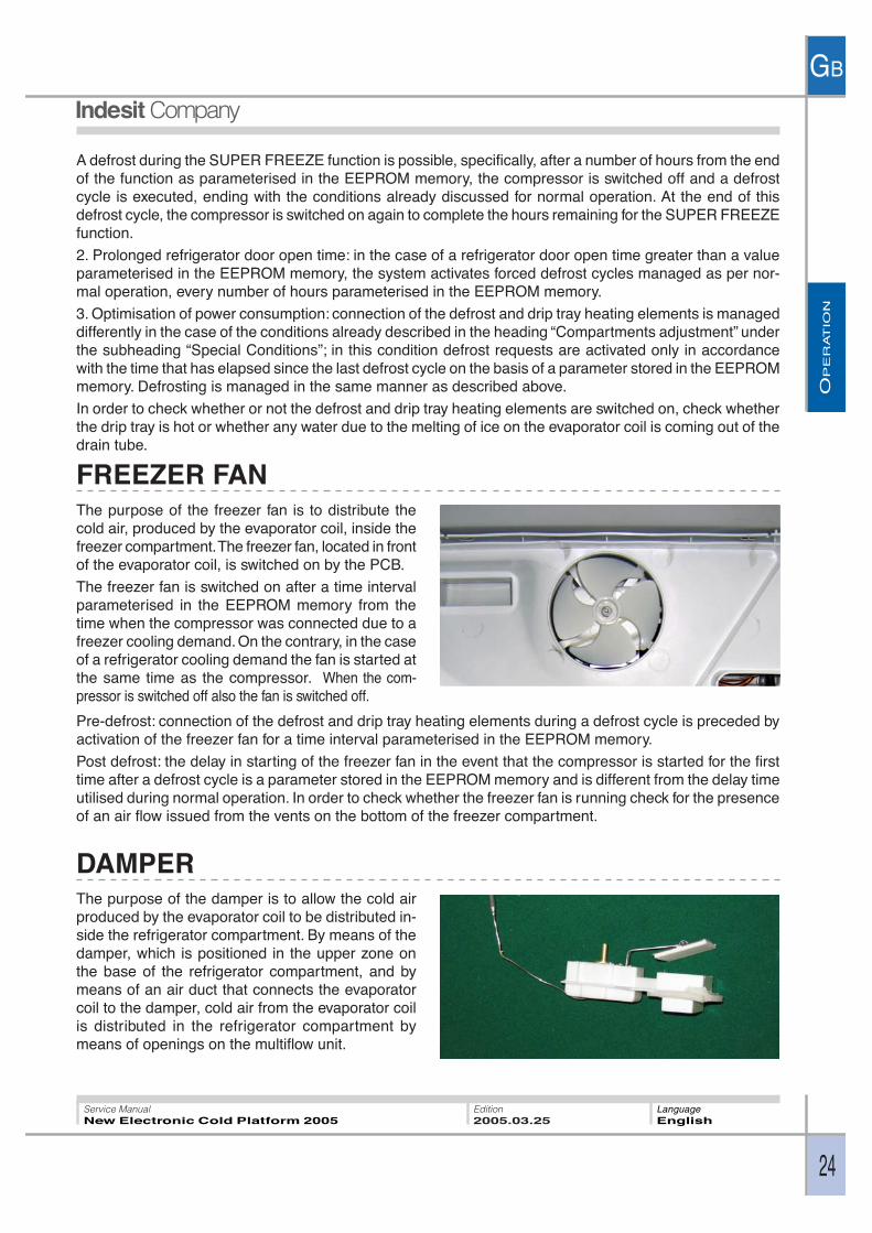
FREEZER FANThe purpose of the freezer fan is to distribute thecold air, produced by the evaporator coil, inside thefreezer compartment. The freezer fan, located in frontof the evaporator coil, is switched on by the PCB.
The freezer fan is switched on after a time intervalparameterised in the EEPROM memory from thetime when the compressor was connected due to afreezer cooling demand. On the contrary, in the caseof a refrigerator cooling demand the fan is started atthe same time as the compressor. When the com-pressor is switched off also the fan is switched off.
Pre-defrost: connection of the defrost and drip tray heating elements during a defrost cycle is preceded byactivation of the freezer fan for a time interval parameterised in the EEPROM memory.
Post defrost: the delay in starting of the freezer fan in the event that the compressor is started for the firsttime after a defrost cycle is a parameter stored in the EEPROM memory and is different from the delay timeutilised during normal operation. In order to check whether the freezer fan is running check for the presenceof an air flow issued from the vents on the bottom of the freezer compartment.
DAMPERThe purpose of the damper is to allow the cold airproduced by the evaporator coil to be distributed in-side the refrigerator compartment. By means of thedamper, which is positioned in the upper zone onthe base of the refrigerator compartment, and bymeans of an air duct that connects the evaporatorcoil to the damper, cold air from the evaporator coilis distributed in the refrigerator compartment bymeans of openings on the multiflow unit.

OP
ER
AT
ION
GB
25
Service ManualNew Electronic Cold Platform 2005
Edition2005.03.25
LanguageEnglish
Opening and closing of the damper are managed by the PCB through the activation of a triac on the board.
The damper is opened in the presence of a cooling demand from the refrigerator compartment and whenthe compressor is running.
When there is no cooling demand from the refrigerator compartment, the damper is closed, even thoughthe compressor may continue to run to meet cooling demand from the freezer compartment.
Pre-defrost: connection of the defrost and drip tray heating elements during a defrost cycle is preceded byopening of the damper and activation of the freezer fan for a time interval parameterised in the EEPROMmemory.
Post defrost: the delay interval before opening the damper if the compressor is started for the first time aftera defrost cycle is a parameter stored in the EEPROM memory.
Refrigerator Door: there exists a condition wherein, despite the fact that the compressor is running, thedamper is not kept open; this is the case in which the refrigerator door is open: in this condition the damperis closed even in the presence of a cooling demand from the refrigerator compartment and when thecompressor is running. The damper is opened again only when the fridge door is closed.
To check opening of the damper check whether there is an air flow from the vents on the base of therefrigerator compartment in the presence of an active cooling demand from the refrigerator compartmentand simulating door closed conditions by applying a magnet.
To check closing of the damper check that there is no air flow from the vents on the multiflow unit on thebase of the refrigerator compartment with the fridge door open and the freezer fan running.
FRIDGE LAMP OPERATION:Housed in a light fixture, the fridge lamp serves toilluminate the refrigerator compartment. The lamp iscontrolled by a triac on the PCB and it switches onwhen the door is opened and switches off when it isclosed.
If the door is kept open for more than a time intervalparameterised on the PCB, the lamp will flash untilthe door is closed.
STATISTICS MANAGEMENT:There are several parameters recorded in the memory that serve to identify the behaviour of the user andthe appliance. The parameters are divided on a daily basis and recorded each week in rolling mode. Whenthe current day is stored in the memory data for the oldest date are deleted.
OP
ER
AT
ION
GB
26
Service ManualNew Electronic Cold Platform 2005
Edition2005.03.25
LanguageEnglish
APPLIANCE THERMODYNAMICS:
(Fig 1) (Fig 2)
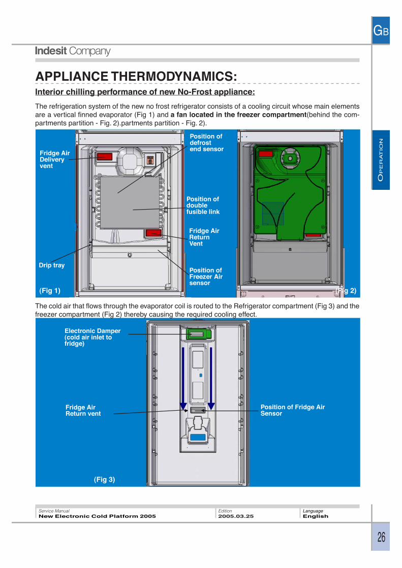
Interior chilling performance of new No-Frost appliance:
The refrigeration system of the new no frost refrigerator consists of a cooling circuit whose main elementsare a vertical finned evaporator (Fig 1) and a fan located in the freezer compartment(behind the com-partments partition - Fig. 2).partments partition - Fig. 2).
(Fig 3)
The cold air that flows through the evaporator coil is routed to the Refrigerator compartment (Fig 3) and thefreezer compartment (Fig 2) thereby causing the required cooling effect.
Electronic Damper(cold air inlet tofridge)
Fridge AirReturn vent
Position of Fridge AirSensor
Drip tray
Fridge AirDeliveryvent
Position ofFreezer Airsensor
Fridge AirReturnVent
Position ofdoublefusible link
Position ofdefrostend sensor
OP
ER
AT
ION
GB
27
Service ManualNew Electronic Cold Platform 2005
Edition2005.03.25
LanguageEnglish
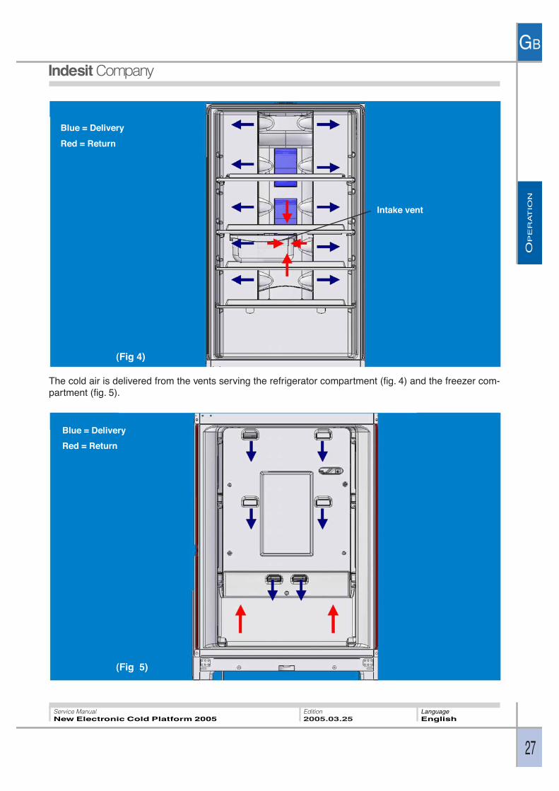
The cold air is delivered from the vents serving the refrigerator compartment (fig. 4) and the freezer com-partment (fig. 5).
(Fig 5)
(Fig 4)
Blue = Delivery
Red = Return
Intake vent
Blue = Delivery
Red = Return
OP
ER
AT
ION
GB
28
Service ManualNew Electronic Cold Platform 2005
Edition2005.03.25
LanguageEnglish
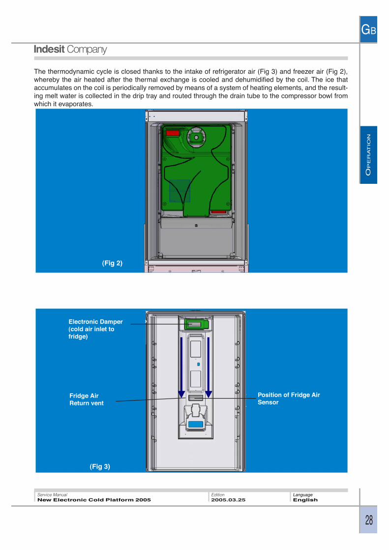
The thermodynamic cycle is closed thanks to the intake of refrigerator air (Fig 3) and freezer air (Fig 2),whereby the air heated after the thermal exchange is cooled and dehumidified by the coil. The ice thataccumulates on the coil is periodically removed by means of a system of heating elements, and the result-ing melt water is collected in the drip tray and routed through the drain tube to the compressor bowl fromwhich it evaporates.
(Fig 2)
(Fig 3)
Electronic Damper(cold air inlet tofridge)
Fridge AirReturn vent
Position of Fridge AirSensor
OP
ER
AT
ION
GB
29
Service ManualNew Electronic Cold Platform 2005
Edition2005.03.25
LanguageEnglish
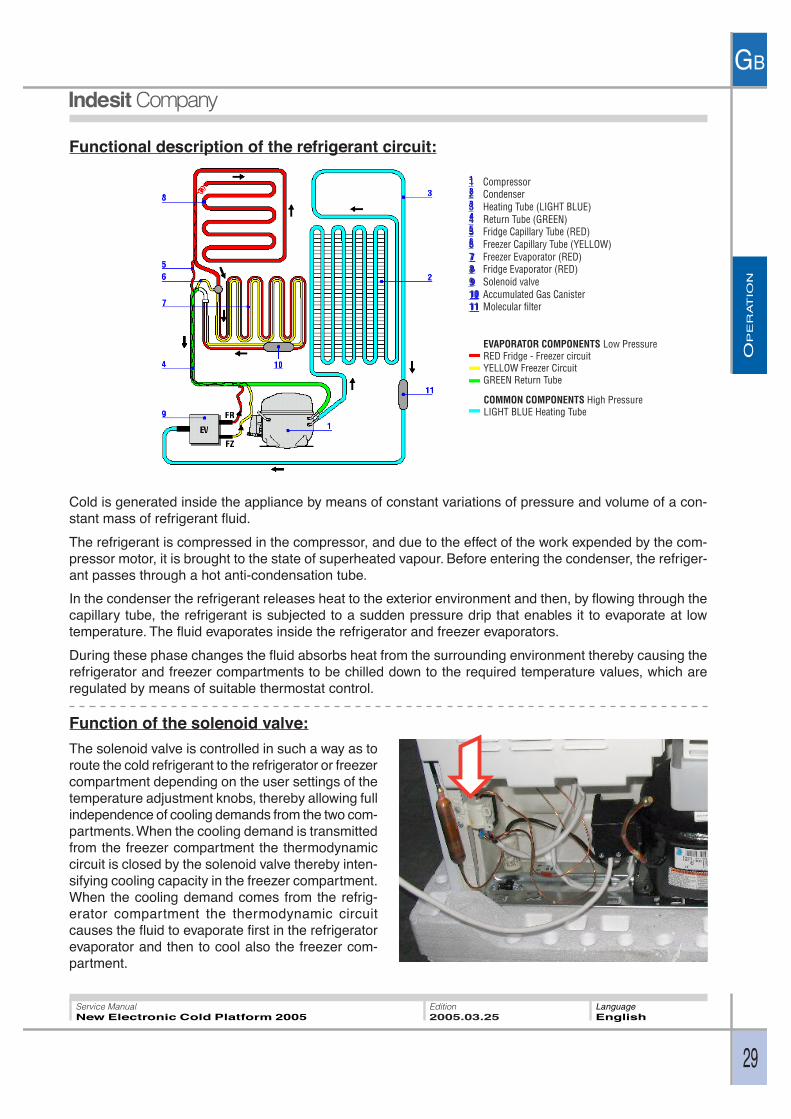
Functional description of the refrigerant circuit:
Cold is generated inside the appliance by means of constant variations of pressure and volume of a con-stant mass of refrigerant fluid.
The refrigerant is compressed in the compressor, and due to the effect of the work expended by the com-pressor motor, it is brought to the state of superheated vapour. Before entering the condenser, the refriger-ant passes through a hot anti-condensation tube.
In the condenser the refrigerant releases heat to the exterior environment and then, by flowing through thecapillary tube, the refrigerant is subjected to a sudden pressure drip that enables it to evaporate at lowtemperature. The fluid evaporates inside the refrigerator and freezer evaporators.
During these phase changes the fluid absorbs heat from the surrounding environment thereby causing therefrigerator and freezer compartments to be chilled down to the required temperature values, which areregulated by means of suitable thermostat control.
Function of the solenoid valve:
The solenoid valve is controlled in such a way as toroute the cold refrigerant to the refrigerator or freezercompartment depending on the user settings of thetemperature adjustment knobs, thereby allowing fullindependence of cooling demands from the two com-partments. When the cooling demand is transmittedfrom the freezer compartment the thermodynamiccircuit is closed by the solenoid valve thereby inten-sifying cooling capacity in the freezer compartment.When the cooling demand comes from the refrig-erator compartment the thermodynamic circuitcauses the fluid to evaporate first in the refrigeratorevaporator and then to cool also the freezer com-partment.
1 Compressor2 Condenser3 Heating Tube (LIGHT BLUE)4 Return Tube (GREEN)5 Fridge Capillary Tube (RED)6 Freezer Capillary Tube (YELLOW)7 Freezer Evaporator (RED)8 Fridge Evaporator (RED)9 Solenoid valve10 Accumulated Gas Canister11 Molecular filter
EVAPORATOR COMPONENTS Low PressureRED Fridge - Freezer circuitYELLOW Freezer CircuitGREEN Return Tube
COMMON COMPONENTS High PressureLIGHT BLUE Heating Tube
CO
MP
ON
EN
TS
GB
30
Service ManualNew Electronic Cold Platform 2005
Edition2005.03.25
LanguageEnglish
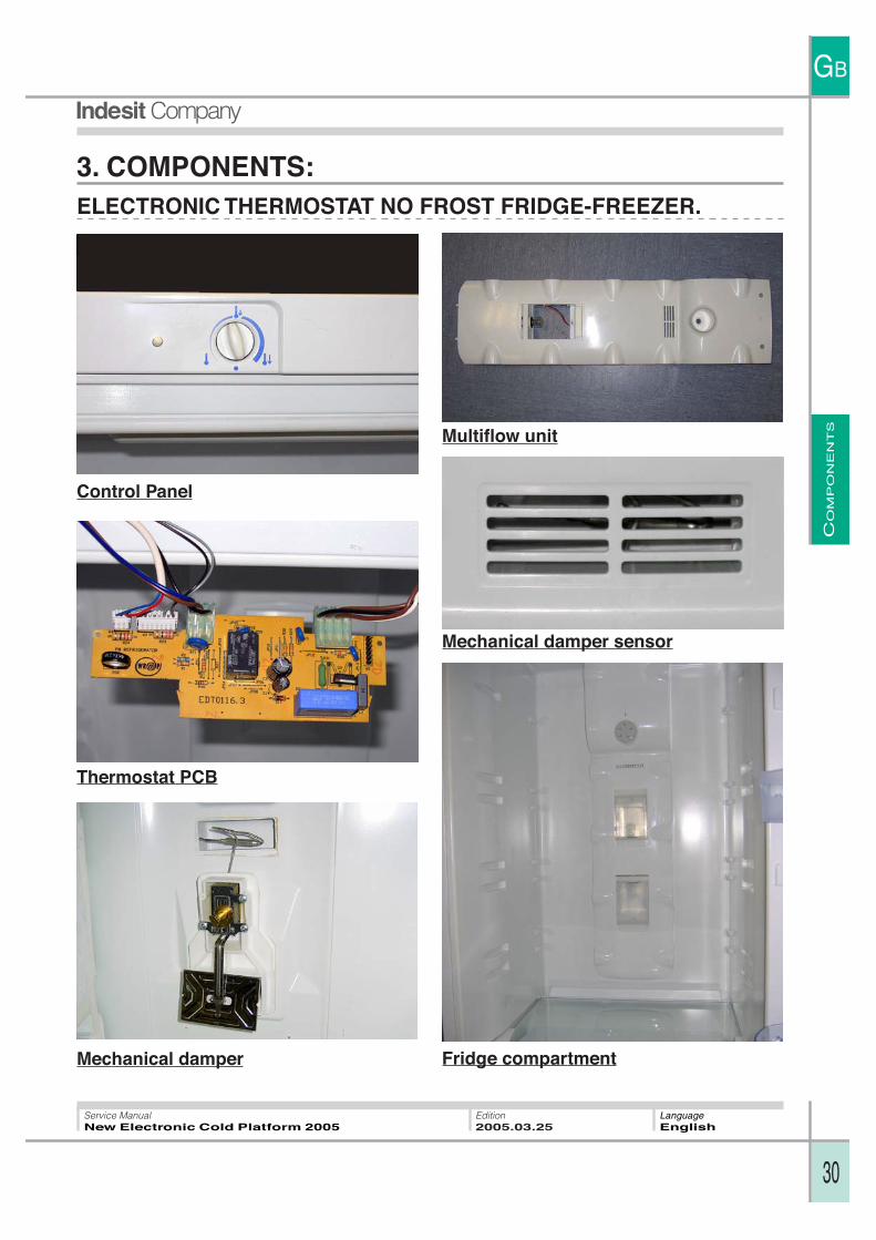
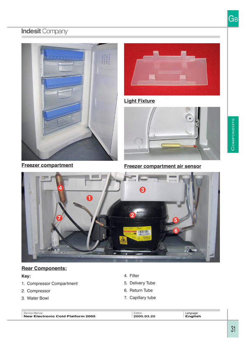
3. COMPONENTS:ELECTRONIC THERMOSTAT NO FROST FRIDGE-FREEZER.
Control Panel
Thermostat PCB
Multiflow unit
Mechanical damper Fridge compartment
Mechanical damper sensor
CO
MP
ON
EN
TS
GB
31
Service ManualNew Electronic Cold Platform 2005
Edition2005.03.25
LanguageEnglish
1
2
34
5
6
7
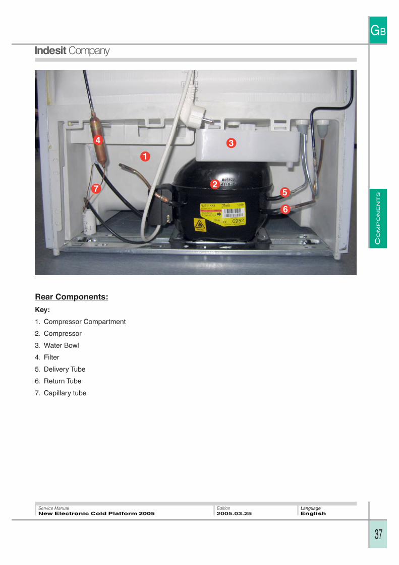
Rear Components:
Key:
1. Compressor Compartment
2. Compressor
3. Water Bowl
4. Filter
5. Delivery Tube
6. Return Tube
7. Capillary tube
Light Fixture
Freezer compartment air sensorFreezer compartment

CO
MP
ON
EN
TS
GB
32
Service ManualNew Electronic Cold Platform 2005
Edition2005.03.25
LanguageEnglish
BASIC ELECTRONIC STATIC FRIDGE-FREEZER OR EVOLUTION MODEL
Basic control panel Evolution control panel
Freezer Air Sensor Freezer Evaporator
Fridge compartment Freezer compartment

CO
MP
ON
EN
TS
GB
33
Service ManualNew Electronic Cold Platform 2005
Edition2005.03.25
LanguageEnglish
Fridge fan (evolution model only) andlamp holder Ice container and drawer
Main PCB (strip) Display/Interface PCB:
Evolution
Base
Main PCB Cover:1. Main PCB Cover
2. Hardware Key Interface
1
2
CO
MP
ON
EN
TS
GB
34
Service ManualNew Electronic Cold Platform 2005
Edition2005.03.25
LanguageEnglish
1
2
3
45
6
7
8
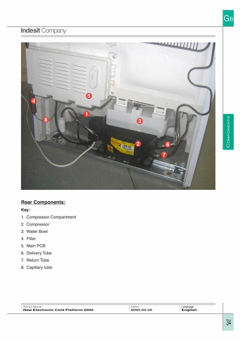
Rear Components:
Key:
1. Compressor Compartment
2. Compressor
3. Water Bowl
4. Filter
5. Main PCB
6. Delivery Tube
7. Return Tube
8. Capillary tube
CO
MP
ON
EN
TS
GB
35
Service ManualNew Electronic Cold Platform 2005
Edition2005.03.25
LanguageEnglish
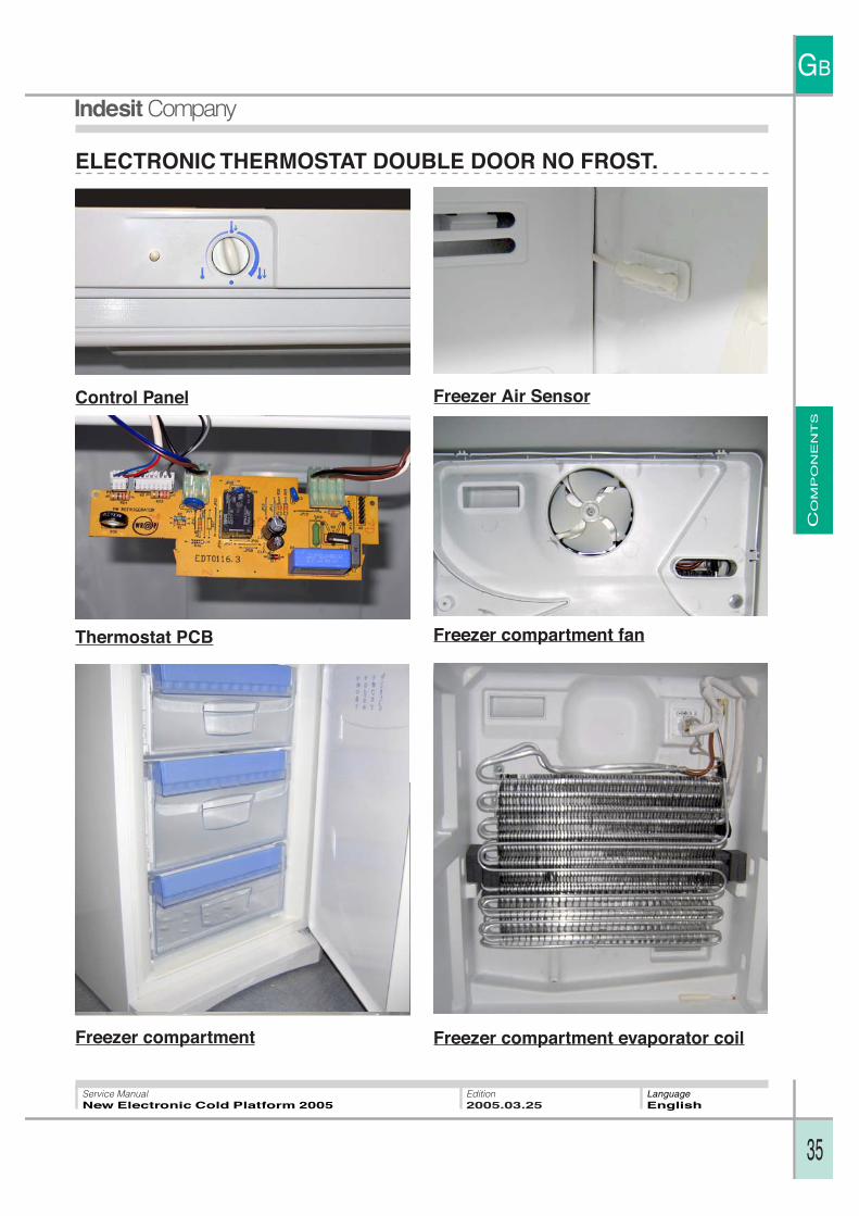
ELECTRONIC THERMOSTAT DOUBLE DOOR NO FROST.
Thermostat PCB
Control Panel
Freezer compartment fan
Freezer Air Sensor
Freezer compartment evaporator coilFreezer compartment
CO
MP
ON
EN
TS
GB
36
Service ManualNew Electronic Cold Platform 2005
Edition2005.03.25
LanguageEnglish
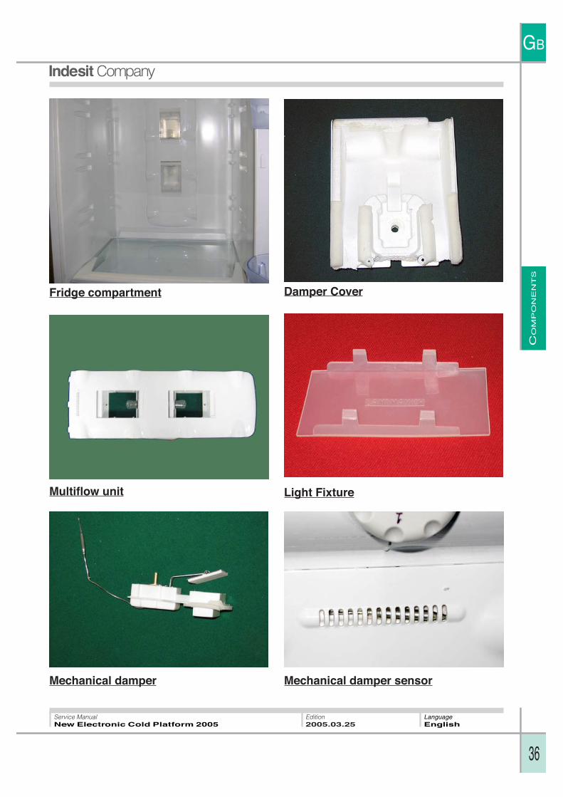
Fridge compartment
Mechanical damper
Damper Cover
Mechanical damper sensor
Light FixtureMultiflow unit
CO
MP
ON
EN
TS
GB
37
Service ManualNew Electronic Cold Platform 2005
Edition2005.03.25
LanguageEnglish
1
2
34
5
6
7
Rear Components:
Key:
1. Compressor Compartment
2. Compressor
3. Water Bowl
4. Filter
5. Delivery Tube
6. Return Tube
7. Capillary tube
CO
MP
ON
EN
TS
GB
38
Service ManualNew Electronic Cold Platform 2005
Edition2005.03.25
LanguageEnglish
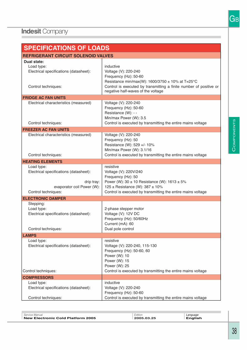
SPECIFICATIONS OF LOADSREFRIGERANT CIRCUIT SOLENOID VALVESDual state:
Load type: inductiveElectrical specifications (datasheet): Voltage (V): 220-240
Frequency (Hz): 50-60Resistance min/max(W): 1600/3750 ± 10% at T=25°C
Control techniques: Control is executed by transmitting a finite number of positive ornegative half-waves of the voltage
FRIDGE AC FAN UNITSElectrical characteristics (measured) Voltage (V): 220-240
Frequency (Hz): 50-60Resistance (W): - -Min/max Power (W): 3.5
Control techniques: Control is executed by transmitting the entire mains voltage
FREEZER AC FAN UNITSElectrical characteristics (measured) Voltage (V): 220-240
Frequency (Hz): 50Resistance (W): 529 +/- 10%Min/max Power (W): 3.1/16
Control techniques: Control is executed by transmitting the entire mains voltage
HEATING ELEMENTSLoad type: resistiveElectrical specifications (datasheet): Voltage (V): 220V/240
Frequency (Hz): 50drip tray: Power (W): 30 ± 10 Resistance (W): 1613 ± 5%
evaporator coil Power (W): 125 ± Resistance (W): 387 ± 10%Control techniques: Control is executed by transmitting the entire mains voltage
ELECTRONIC DAMPERStepping:Load type: 2-phase stepper motorElectrical specifications (datasheet): Voltage (V): 12V DC
Frequency (Hz): 50/60HzCurrent (mA): 60
Control techniques: Dual pole control
LAMPSLoad type: resistiveElectrical specifications (datasheet): Voltage (V): 220-240, 115-130
Frequency (Hz): 50-60, 60Power (W): 10Power (W): 15Power (W): 25
Control techniques: Control is executed by transmitting the entire mains voltage
COMPRESSORSLoad type: inductiveElectrical specifications (datasheet): Voltage (V): 220-240
Frequency (Hz): 50-60Control techniques: Control is executed by transmitting the entire mains voltage
WIR
ING D
IAG
RA
MS
GB
39
Service ManualNew Electronic Cold Platform 2005
Edition2005.03.25
LanguageEnglish
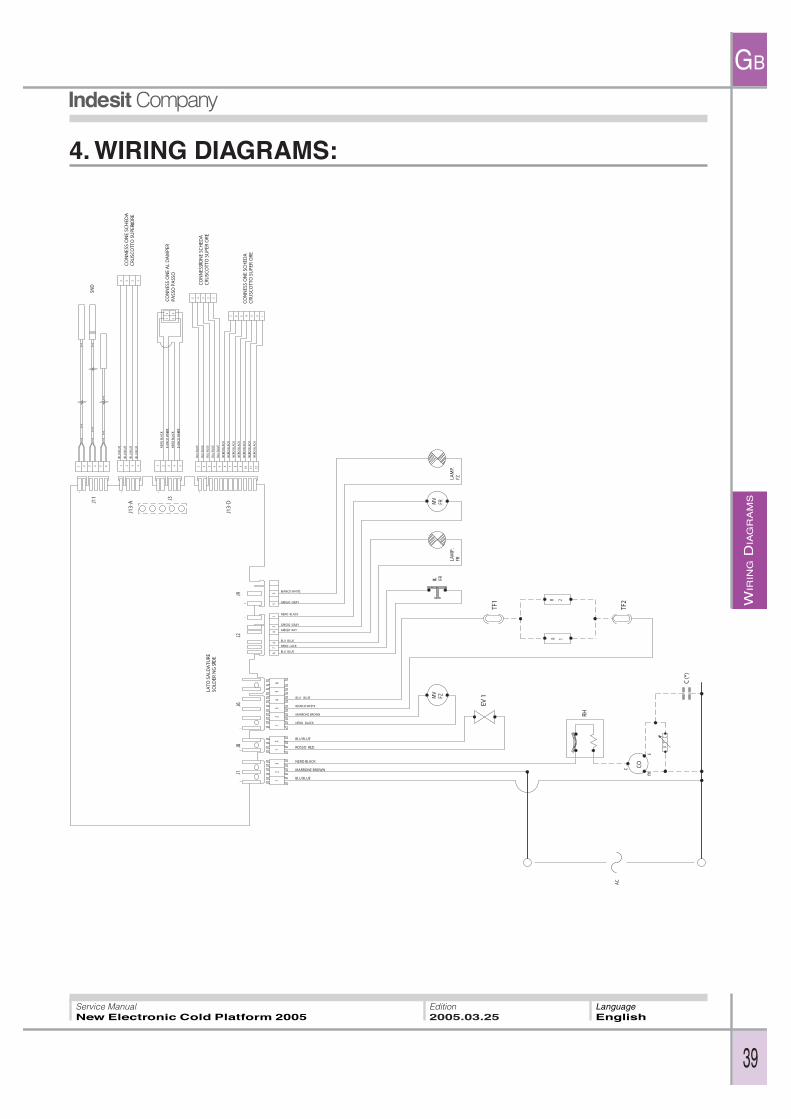
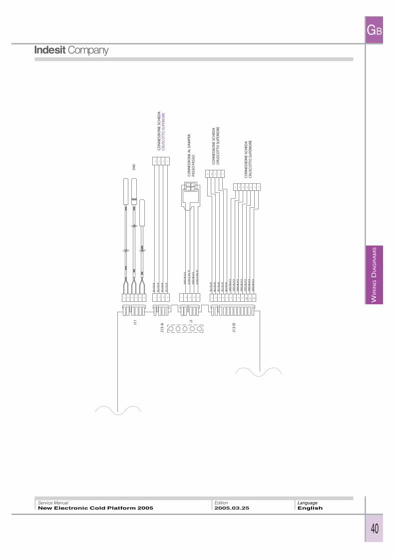
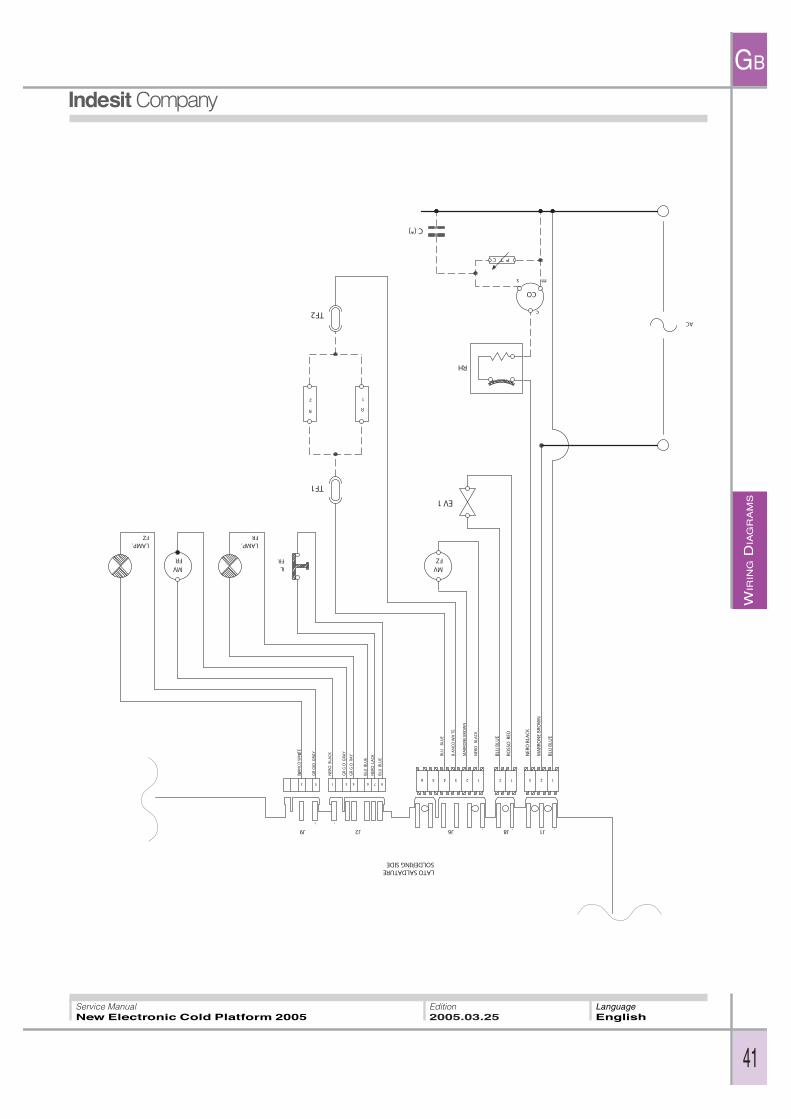
4. WIRING DIAGRAMS:
WIR
ING D
IAG
RA
MS
GB
40
Service ManualNew Electronic Cold Platform 2005
Edition2005.03.25
LanguageEnglish
WIR
ING D
IAG
RA
MS
GB
41
Service ManualNew Electronic Cold Platform 2005
Edition2005.03.25
LanguageEnglish
WIR
ING D
IAG
RA
MS
GB
42
Service ManualNew Electronic Cold Platform 2005
Edition2005.03.25
LanguageEnglish
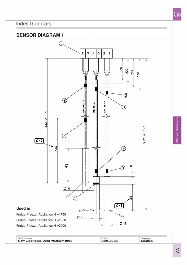
SENSOR DIAGRAM 1
Used in:
Fridge-Freezer Appliance H =1750
Fridge-Freezer Appliance H =1850
Fridge-Freezer Appliance H =2000

WIR
ING D
IAG
RA
MS
GB
43
Service ManualNew Electronic Cold Platform 2005
Edition2005.03.25
LanguageEnglish
SENSOR DIAGRAM 2
Used in:
NF Fridge-Freezer Appliance H =1875
NF Fridge-Freezer Appliance H =2000
WIR
ING D
IAG
RA
MS
GB
44
Service ManualNew Electronic Cold Platform 2005
Edition2005.03.25
LanguageEnglish
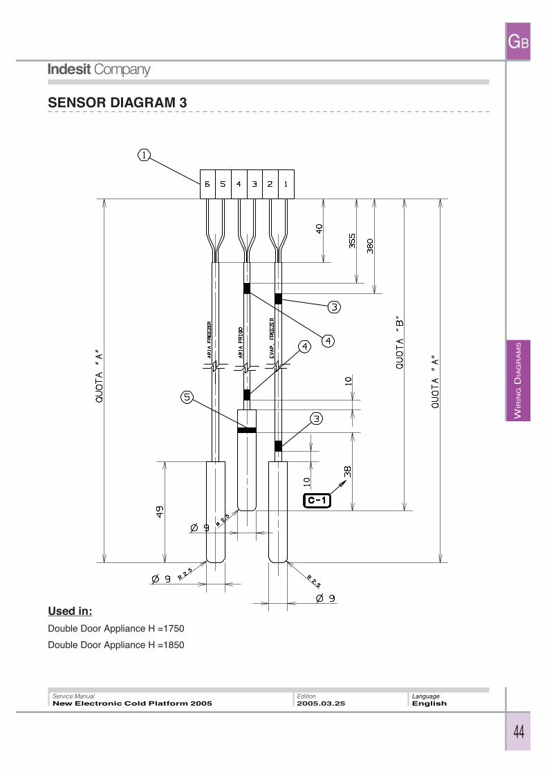
Used in:
Double Door Appliance H =1750
Double Door Appliance H =1850
SENSOR DIAGRAM 3
WIR
ING D
IAG
RA
MS
GB
45
Service ManualNew Electronic Cold Platform 2005
Edition2005.03.25
LanguageEnglish
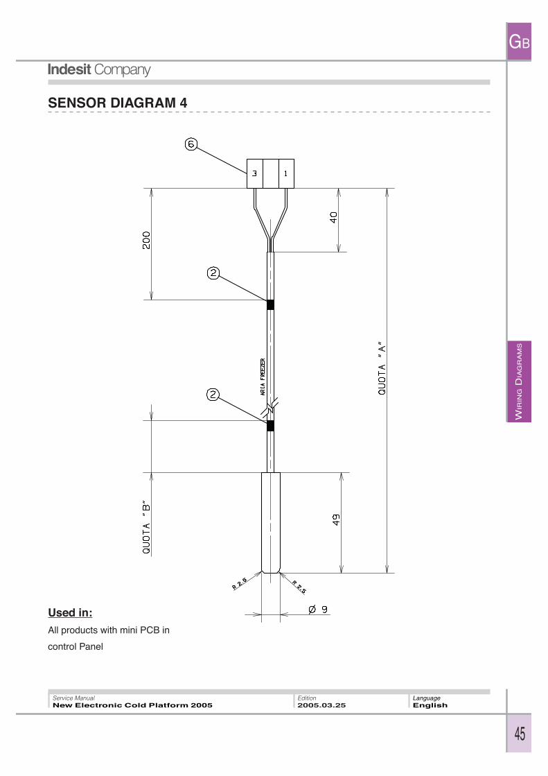
SENSOR DIAGRAM 4
Used in:
All products with mini PCB in
control Panel
WIR
ING D
IAG
RA
MS
GB
46
Service ManualNew Electronic Cold Platform 2005
Edition2005.03.25
LanguageEnglish
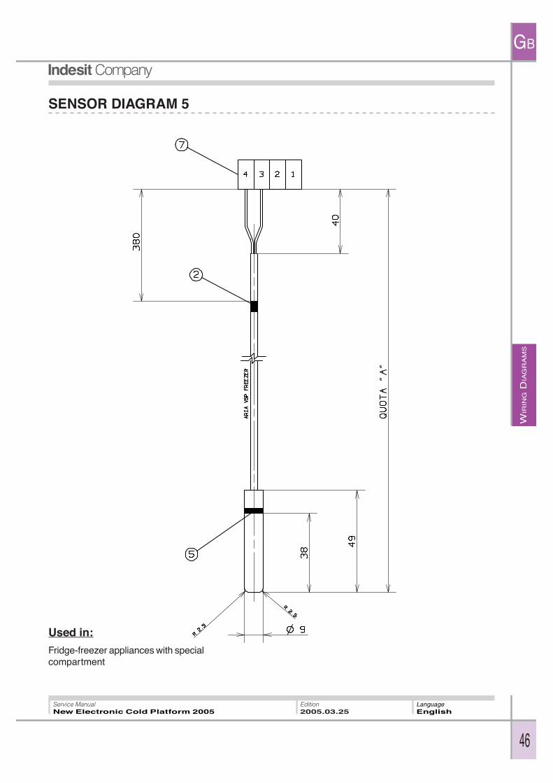
SENSOR DIAGRAM 5
Used in:
Fridge-freezer appliances with specialcompartment
WIR
ING D
IAG
RA
MS
GB
47
Service ManualNew Electronic Cold Platform 2005
Edition2005.03.25
LanguageEnglish
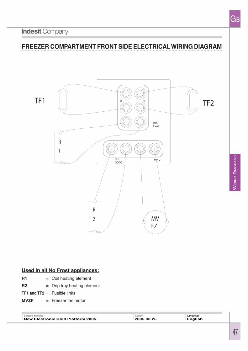
FREEZER COMPARTMENT FRONT SIDE ELECTRICAL WIRING DIAGRAM
Used in all No Frost appliances:
R1 = Coil heating element
R2 = Drip tray heating element
TF1 and TF2 = Fusible links
MVZF = Freezer fan motor
AS
SIS
TA
NC
E
GB
48
Service ManualNew Electronic Cold Platform 2005
Edition2005.03.25
LanguageEnglish
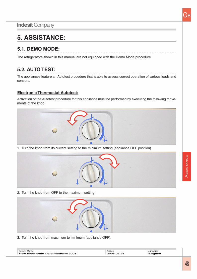
5. ASSISTANCE:
5.1. DEMO MODE:
The refrigerators shown in this manual are not equipped with the Demo Mode procedure.
5.2. AUTO TEST:The appliances feature an Autotest procedure that is able to assess correct operation of various loads andsensors.
Electronic Thermostat Autotest:
Activation of the Autotest procedure for this appliance must be performed by executing the following move-ments of the knob:
1. Turn the knob from its current setting to the minimum setting (appliance OFF position)
2. Turn the knob from OFF to the maximum setting.
3. Turn the knob from maximum to minimum (appliance OFF).
AS
SIS
TA
NC
E
GB
49
Service ManualNew Electronic Cold Platform 2005
Edition2005.03.25
LanguageEnglish
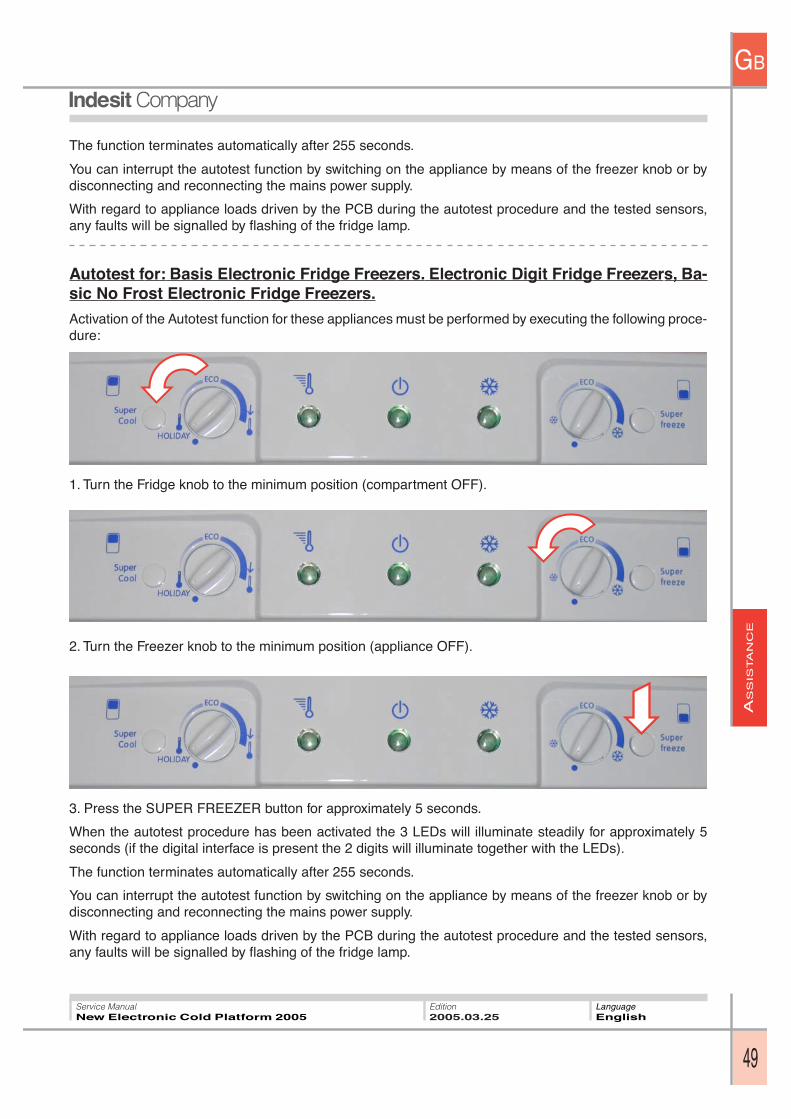
The function terminates automatically after 255 seconds.
You can interrupt the autotest function by switching on the appliance by means of the freezer knob or bydisconnecting and reconnecting the mains power supply.
With regard to appliance loads driven by the PCB during the autotest procedure and the tested sensors,any faults will be signalled by flashing of the fridge lamp.
Autotest for: Basis Electronic Fridge Freezers. Electronic Digit Fridge Freezers, Ba-sic No Frost Electronic Fridge Freezers.
Activation of the Autotest function for these appliances must be performed by executing the following proce-dure:
1. Turn the Fridge knob to the minimum position (compartment OFF).
2. Turn the Freezer knob to the minimum position (appliance OFF).
3. Press the SUPER FREEZER button for approximately 5 seconds.
When the autotest procedure has been activated the 3 LEDs will illuminate steadily for approximately 5seconds (if the digital interface is present the 2 digits will illuminate together with the LEDs).
The function terminates automatically after 255 seconds.
You can interrupt the autotest function by switching on the appliance by means of the freezer knob or bydisconnecting and reconnecting the mains power supply.
With regard to appliance loads driven by the PCB during the autotest procedure and the tested sensors,any faults will be signalled by flashing of the fridge lamp.
AS
SIS
TA
NC
E
GB
50
Service ManualNew Electronic Cold Platform 2005
Edition2005.03.25
LanguageEnglish
1 2 3 54
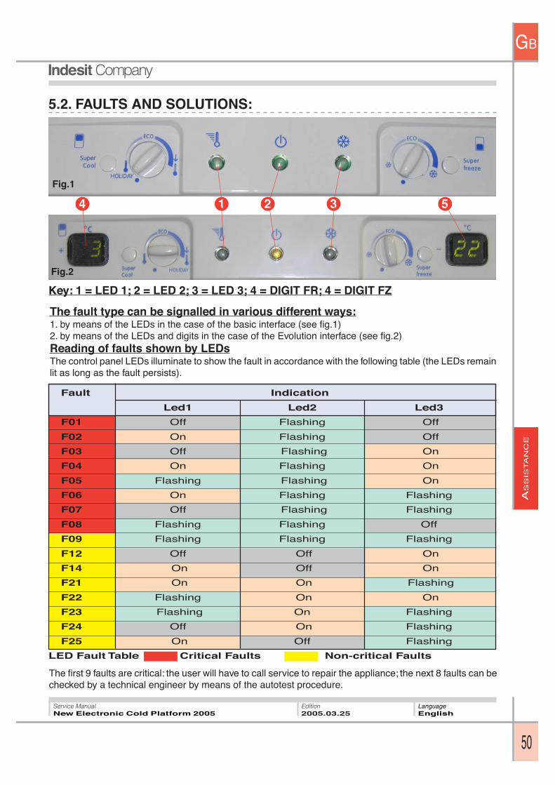
5.2. FAULTS AND SOLUTIONS:
Key: 1 = LED 1; 2 = LED 2; 3 = LED 3; 4 = DIGIT FR; 4 = DIGIT FZ
Fig.2
Fig.1
The fault type can be signalled in various different ways:1. by means of the LEDs in the case of the basic interface (see fig.1)2. by means of the LEDs and digits in the case of the Evolution interface (see fig.2)Reading of faults shown by LEDsThe control panel LEDs illuminate to show the fault in accordance with the following table (the LEDs remainlit as long as the fault persists).
Fault Indication
Led1 Led2 Led3
F01 Off Flashing Off
F02 On Flashing Off
F03 Off Flashing On
F04 On Flashing On
F05 Flashing Flashing On
F06 On Flashing Flashing
F07 Off Flashing Flashing
F08 Flashing Flashing Off
F09 Flashing Flashing Flashing
F12 Off Off On
F14 On Off On
F21 On On Flashing
F22 Flashing On On
F23 Flashing On Flashing
F24 Off On Flashing
F25 On Off Flashing
LED Fault Table Critical Faults Non-critical Faults
The first 9 faults are critical: the user will have to call service to repair the appliance; the next 8 faults can bechecked by a technical engineer by means of the autotest procedure.
AS
SIS
TA
NC
E
GB
51
Service ManualNew Electronic Cold Platform 2005
Edition2005.03.25
LanguageEnglish
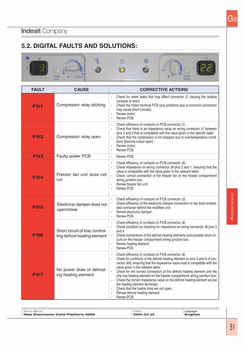
FAULT CORRECTIVE ACTIONSCAUSE
- Check for water leaks that may affect connector J1 causing the relativecontacts to short;
- Check the motor terminal PCB (any problems due to incorrect connectionmay cause short-circuits);
- Renew motor;- Renew PCB.
- Check efficiency of contacts on PCB connector J1;- Check that there is an impedance value on wiring connector J1 between
pins 3 and 2 that is compatible with the value given in the specific table.- Check that the compressor is not stopped due to overtemperature condi-
tions (thermal cutout open)- Renew motor;- Renew PCB.
- Renew PCB.
- Check efficiency of contacts on PCB connector J6;- Check impedance on wiring connector J6 pins 2 and 1, ensuring that the
value is compatible with the value given in the relevant table;- Check correct connection of the freezer fan on the freezer compartment
wiring junction box;- Renew freezer fan unit;- Renew PCB.
- Check efficiency of contacts on PCB connector J3;- Check efficiency of the electronic damper connection to the foam embed-
ded connector behind the multiflow unit;- Renew electronic damper;- Renew PCB.
- Check efficiency of contacts on PCB connector J6;- Check condition by checking for impedance on wiring connector J6 pins 3
and 4- Check connections of the defrost heating elements and possible short cir-
cuits on the freezer compartment wiring junction box;- Renew heating element.- Renew PCB.
- Check efficiency of contacts on PCB connector J6;- Check for continuity of the defrost heating element on pins 3 and 4 of con-
nector JK6, ensuring that the impedance value read is compatible with thevalue given in the relevant table;
- Check for the correct connection of the defrost heating element and thedrip tray heating element on the freezer compartment wiring junction box;
- Check the correct impedance value on the defrost heating element acrossthe heating element terminals;
- Check that the fusible links are not open;- Renew defrost heating element;- Renew PCB.
F01 Compressor relay sticking
Compressor relay open
Faulty power PCBF03
F02
F04Freezer fan unit does notrun
5.2. DIGITAL FAULTS AND SOLUTIONS:
F07
F06
F05Electronic damper does notopen/close
Short circuit of triac control-ling defrost heating element
No power draw of defrost-ing heating element
AS
SIS
TA
NC
E
GB
52
Service ManualNew Electronic Cold Platform 2005
Edition2005.03.25
LanguageEnglish
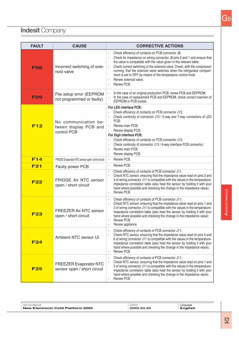
FAULT CORRECTIVE ACTIONSCAUSE
- Check efficiency of contacts on PCB connector J8;- Check for impedance on wiring connector J8 pins 2 and 1 and ensure that
the value is compatible with the value given in the relevant table;- Check correct switching of the solenoid valve. Check, with the compressor
running, that the solenoid valve switches when the refrigerator compart-ment is set to OFF by means of the temperature control knob
- Renew solenoid valve;- Renew PCB.
- In the case of an original production PCB, renew PCB and EEPROM;- In the case of replacement PCB and EEPROM, check correct insertion of
EEPROM in PCB socket.
For LED interface PCB:- Check efficiency of contacts on PCB connector J13;- Check continuity of connector J13 / 5-way and 7-way connectors of LED
PCB;- Renew main PCB;- Renew display PCB;For Digit interface PCB:- Check efficiency of contacts on PCB connector J13;- Check continuity of connector J13 / 4-way interface PCB connector;- Renew main PCB;- Renew display PCB.- Renew PCB.
- Renew PCB.
- Check efficiency of contacts of PCB connector J11;- Check NTC sensor, ensuring that the impedance value read on pins 3 and
4 of wiring connector J11 is compatible with the values in the temperature-impedance correlation table (also heat the sensor by holding it with yourhand where possible and checking the change in the impedance value);
- Renew PCB.
- Check efficiency of contacts of PCB connector J11;- Check NTC sensor, ensuring that the impedance value read on pins 1 and
2 of wiring connector J11 is compatible with the values in the temperature-impedance correlation table (also heat the sensor by holding it with yourhand where possible and checking the change in the impedance value)
- Renew PCB.- Renew appliance
- Check efficiency of contacts of PCB connector J11;- Check NTC sensor, ensuring that the impedance value read on pins 5 and
6 of wiring connector J11 is compatible with the values in the temperature-impedance correlation table (also heat the sensor by holding it with yourhand where possible and checking the change in the impedance value);
- Renew PCB.
- Check efficiency of contacts of PCB connector J11;- Check NTC sensor, ensuring that the impedance value read on pins 1 and
2 of wiring connector J11 is compatible with the values in the temperature-impedance correlation table (also heat the sensor by holding it with yourhand where possible and checking the change in the impedance value)
- Renew PCB.
F08 Incorrect switching of sole-noid valve
File setup error (EEPROMnot programmed or faulty).
No communication be-tween display PCB andcontrol PCB
F12
F09
F23FREEZER Air NTC sensoropen / short circuit
F24
F22
F14 FRIDGE Evaporator NTC sensor open / short circuit
FRIDGE Air NTC sensoropen / short circuit
Ambient NTC sensor UI
F21 Faulty power PCB
F25FREEZER Evaporator NTCsensor open / short circuit
AS
SIS
TA
NC
E
GB
53
Service ManualNew Electronic Cold Platform 2005
Edition2005.03.25
LanguageEnglish
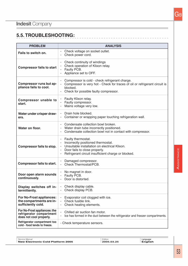
5.5. TROUBLESHOOTING:
ANALYSISPROBLEM
Fails to switch on.
Compressor fails to start
Compressor runs but ap-pliance fails to cool.
Compressor unable tostart.
- Check voltage on socket outlet.- Check power cord.
- Check continuity of windings- Check operation of Klixon relay.- Faulty PCB.- Appliance set to OFF.
- Compressor is cold - check refrigerant charge.- Compressor is very hot - Check for traces of oil or refrigerant circuit is
blocked.- Check for possible faulty compressor.
- Faulty Klixon relay.- Faulty compressor.- Mains voltage very low.
- Drain hole blocked.- Container or wrapping paper touching refrigeration wall.
- Condensate collection bowl broken.- Water drain tube incorrectly positioned.- Condensate collection bowl not in contact with compressor.
- Faulty thermostat.- Incorrectly positioned thermostat.- Unsuitable installation on electrical Klixon.- Door fails to close properly.- Refrigerant circuit insufficient charge or blocked.
- Damaged compressor.- Check Thermostat/PCB.
- No magnet in door.- Faulty PCB.- Door is distorted.
- Check display cable.- Check display PCB.
- Evaporator coil clogged with ice.- Check fusible link.- Check heating elements.
- Chilled air suction fan motor.- Ice has formed in the duct between the refrigerator and freezer compartments.
- Check temperature sensors.
Water under crisper draw-ers.
Water on floor.
Compressor fails to stop.
Compressor fails to start.
Door open alarm soundscontinuously.
Display switches off in-termittently.
For No-Frost appliances:the compartments are in-sufficiently cold.
For No-Frost appliances: therefrigerator compartmentdoes not cool properly.Refrigerator compartment toocold - food tends to freeze.
AS
SIS
TA
NC
E
GB
54
Service ManualNew Electronic Cold Platform 2005
Edition2005.03.25
LanguageEnglish
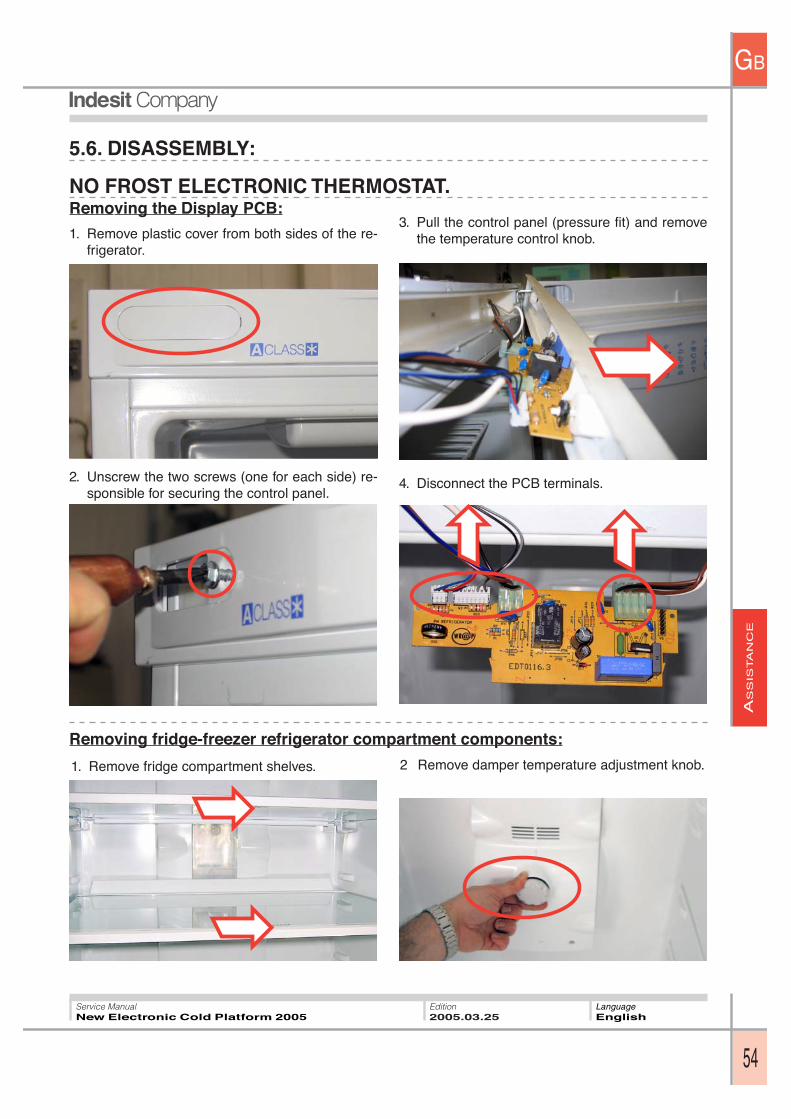
5.6. DISASSEMBLY:
Removing the Display PCB:
1. Remove plastic cover from both sides of the re-frigerator.
2. Unscrew the two screws (one for each side) re-sponsible for securing the control panel.
3. Pull the control panel (pressure fit) and removethe temperature control knob.
4. Disconnect the PCB terminals.
NO FROST ELECTRONIC THERMOSTAT.
1. Remove fridge compartment shelves. 2 Remove damper temperature adjustment knob.
Removing fridge-freezer refrigerator compartment components:
AS
SIS
TA
NC
E
GB
55
Service ManualNew Electronic Cold Platform 2005
Edition2005.03.25
LanguageEnglish
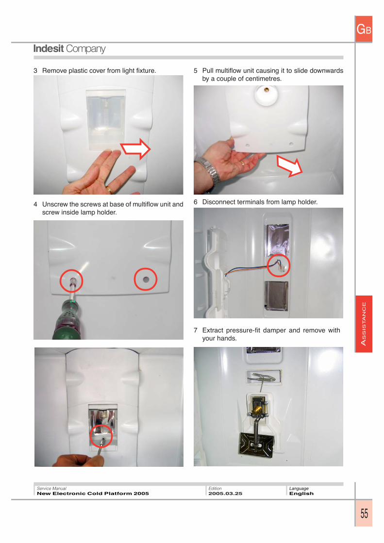
3 Remove plastic cover from light fixture.
4 Unscrew the screws at base of multiflow unit andscrew inside lamp holder.
5 Pull multiflow unit causing it to slide downwardsby a couple of centimetres.
6 Disconnect terminals from lamp holder.
7 Extract pressure-fit damper and remove withyour hands.
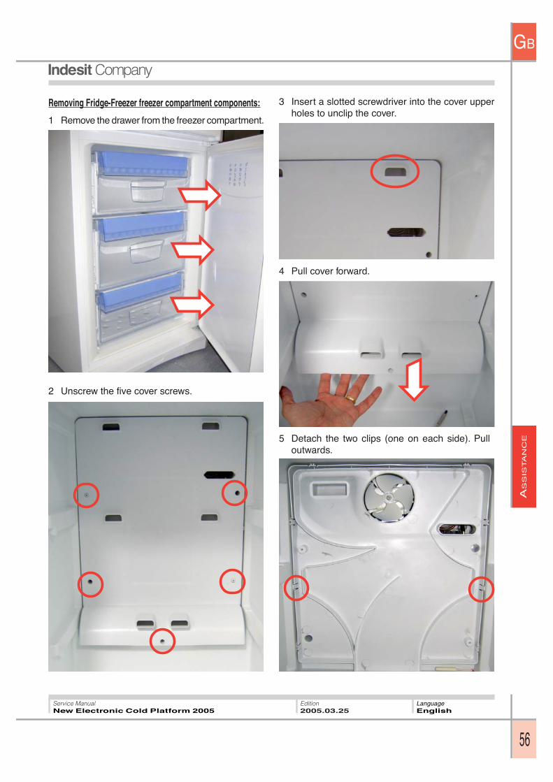
AS
SIS
TA
NC
E
GB
56
Service ManualNew Electronic Cold Platform 2005
Edition2005.03.25
LanguageEnglish
Removing Fridge-Freezer freezer compartment components:
1 Remove the drawer from the freezer compartment.
2 Unscrew the five cover screws.
3 Insert a slotted screwdriver into the cover upperholes to unclip the cover.
4 Pull cover forward.
5 Detach the two clips (one on each side). Pulloutwards.
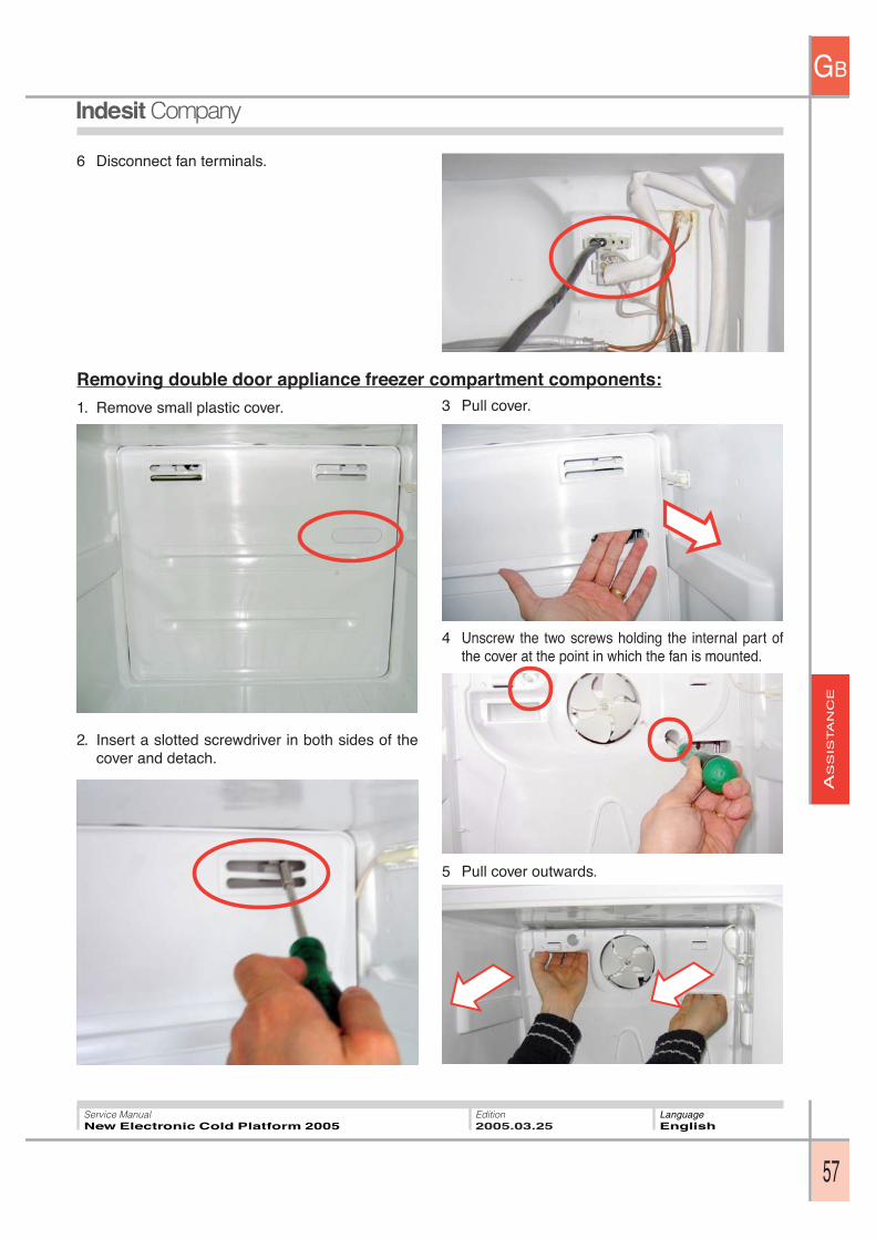
AS
SIS
TA
NC
E
GB
57
Service ManualNew Electronic Cold Platform 2005
Edition2005.03.25
LanguageEnglish
6 Disconnect fan terminals.
Removing double door appliance freezer compartment components:
2. Insert a slotted screwdriver in both sides of thecover and detach.
3 Pull cover.
4 Unscrew the two screws holding the internal part ofthe cover at the point in which the fan is mounted.
5 Pull cover outwards.
1. Remove small plastic cover.
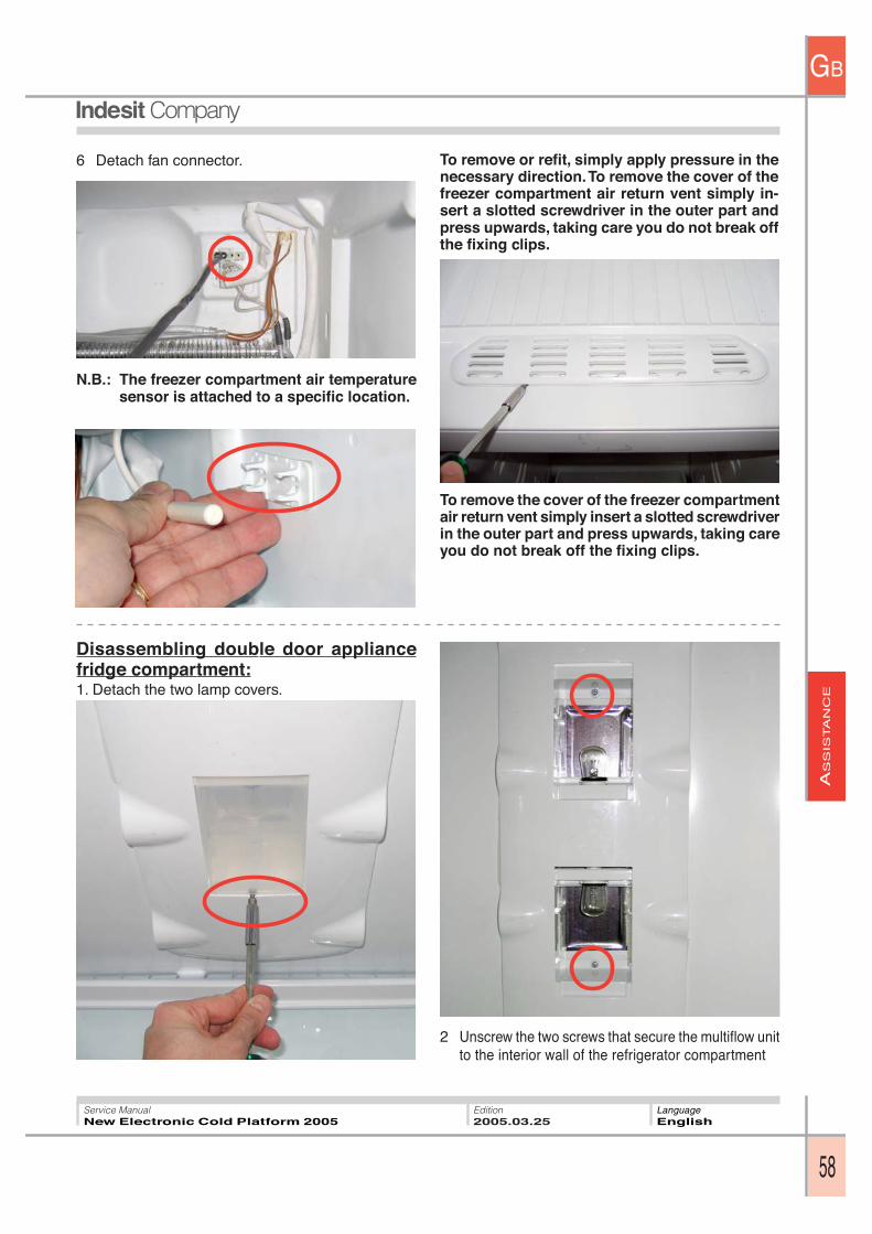
AS
SIS
TA
NC
E
GB
58
Service ManualNew Electronic Cold Platform 2005
Edition2005.03.25
LanguageEnglish
3. Una volta svitato tirarlo.
Disassembling double door appliancefridge compartment:1. Detach the two lamp covers.
6 Detach fan connector.
N.B.: The freezer compartment air temperaturesensor is attached to a specific location.
To remove or refit, simply apply pressure in thenecessary direction. To remove the cover of thefreezer compartment air return vent simply in-sert a slotted screwdriver in the outer part andpress upwards, taking care you do not break offthe fixing clips.
2 Unscrew the two screws that secure the multiflow unitto the interior wall of the refrigerator compartment
To remove the cover of the freezer compartmentair return vent simply insert a slotted screwdriverin the outer part and press upwards, taking careyou do not break off the fixing clips.
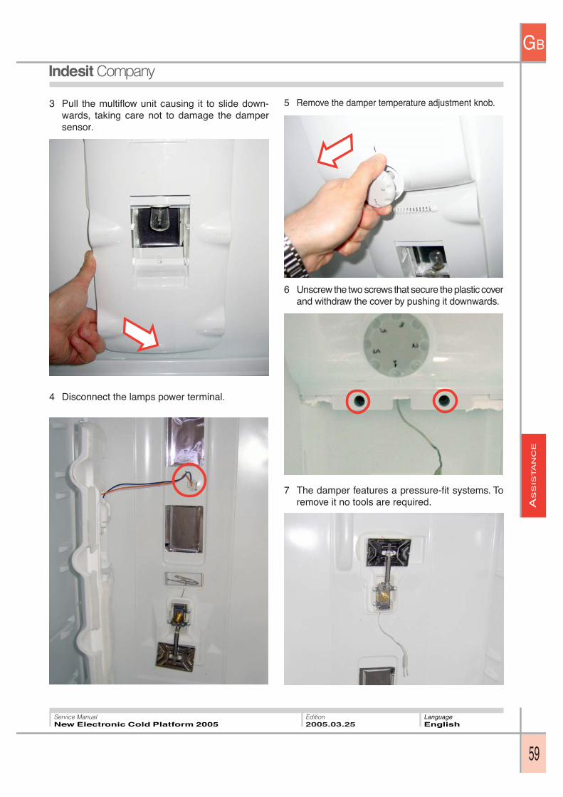
AS
SIS
TA
NC
E
GB
59
Service ManualNew Electronic Cold Platform 2005
Edition2005.03.25
LanguageEnglish
3 Pull the multiflow unit causing it to slide down-wards, taking care not to damage the dampersensor.
4 Disconnect the lamps power terminal.
5 Remove the damper temperature adjustment knob.
6 Unscrew the two screws that secure the plastic coverand withdraw the cover by pushing it downwards.
7 The damper features a pressure-fit systems. Toremove it no tools are required.
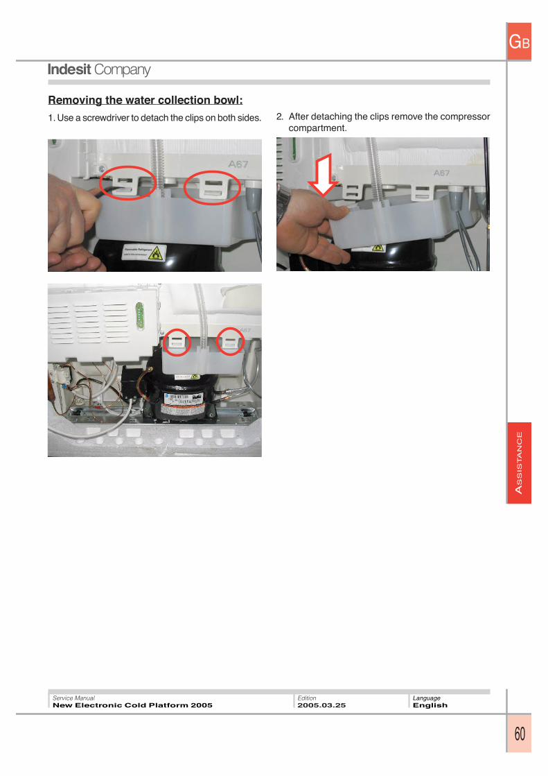
AS
SIS
TA
NC
E
GB
60
Service ManualNew Electronic Cold Platform 2005
Edition2005.03.25
LanguageEnglish
Removing the water collection bowl:
1. Use a screwdriver to detach the clips on both sides. 2. After detaching the clips remove the compressorcompartment.

AS
SIS
TA
NC
E
GB
61
Service ManualNew Electronic Cold Platform 2005
Edition2005.03.25
LanguageEnglish
Removing the Display PCB:
1. Remove plastic cover from both sides of the re-frigerator.
3. Disconnect the PCB terminals.
BASIC ELECTRONIC STATIC FRIDGE-FREEZER OR EVOLUTION MODEL
2 Unscrew the two screws (one on each side) re-sponsible for securing the control panel.
4. Press the fixing tabs and remove the PCB
Removing the fan:
1. Remove the refrigerator fan cover by pressing withyour hand on one of the two sides and then ex-tract it.
2. Unscrew the two screws (one on each side) re-sponsible for fixing the fan.
3. Detach the connector.
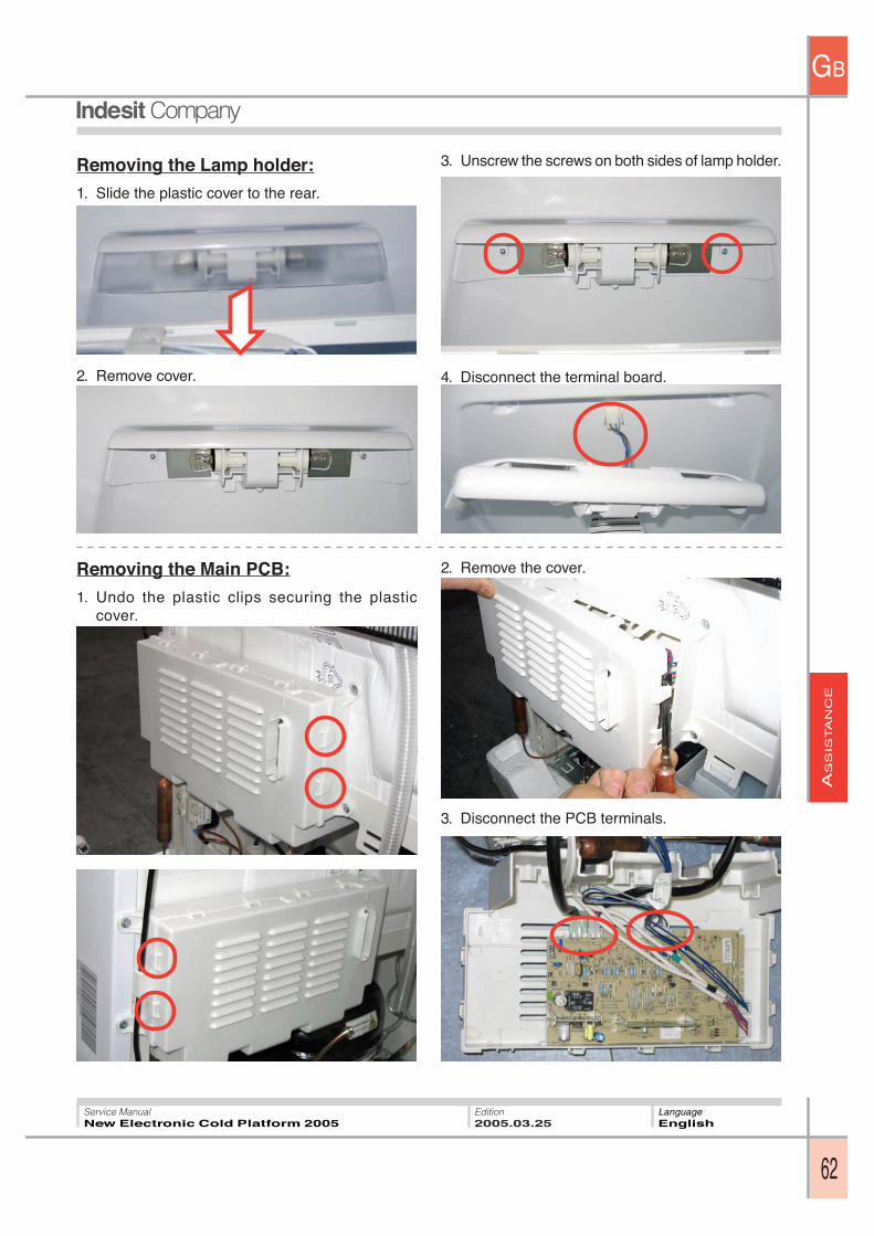
AS
SIS
TA
NC
E
GB
62
Service ManualNew Electronic Cold Platform 2005
Edition2005.03.25
LanguageEnglish
Removing the Lamp holder:
1. Slide the plastic cover to the rear.
3. Unscrew the screws on both sides of lamp holder.
2. Remove cover. 4. Disconnect the terminal board.
Removing the Main PCB:
1. Undo the plastic clips securing the plasticcover.
2. Remove the cover.
3. Disconnect the PCB terminals.
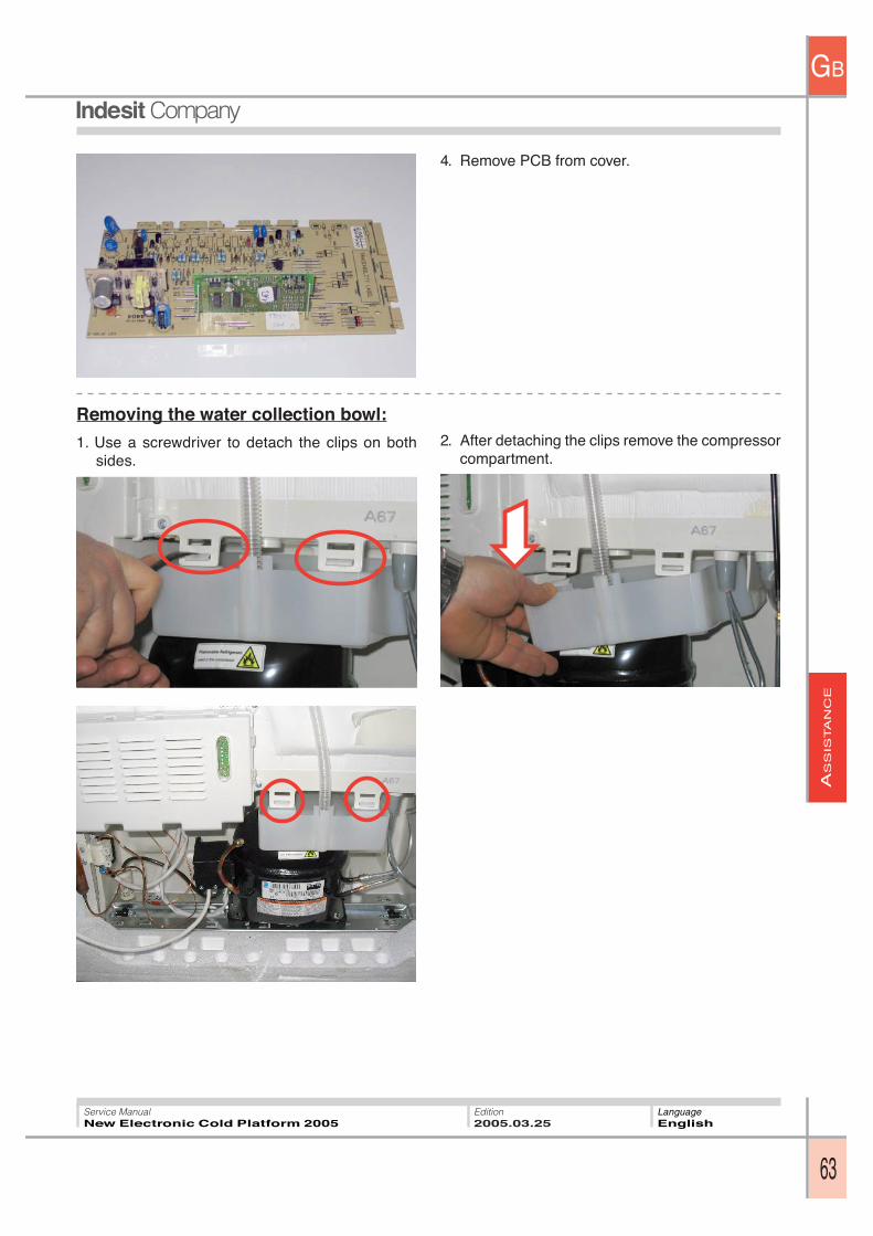
AS
SIS
TA
NC
E
GB
63
Service ManualNew Electronic Cold Platform 2005
Edition2005.03.25
LanguageEnglish
Removing the water collection bowl:
1. Use a screwdriver to detach the clips on bothsides.
4. Remove PCB from cover.
2. After detaching the clips remove the compressorcompartment.
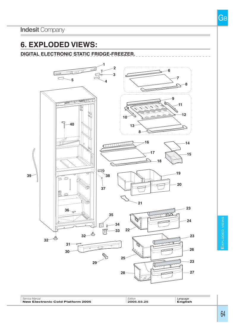
EX
PLO
DE
DV
IEW
S
GB
64
Service ManualNew Electronic Cold Platform 2005
Edition2005.03.25
LanguageEnglish
6. EXPLODED VIEWS:DIGITAL ELECTRONIC STATIC FRIDGE-FREEZER.
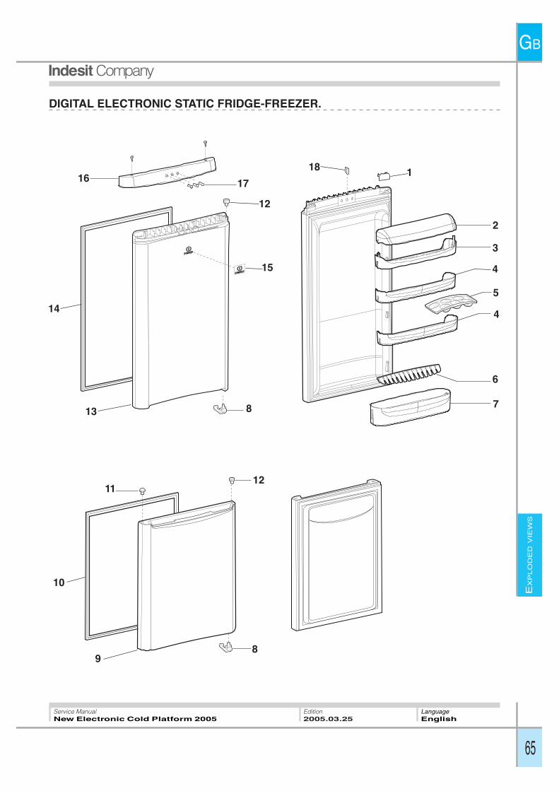
EX
PLO
DE
DV
IEW
S
GB
65
Service ManualNew Electronic Cold Platform 2005
Edition2005.03.25
LanguageEnglish
DIGITAL ELECTRONIC STATIC FRIDGE-FREEZER.
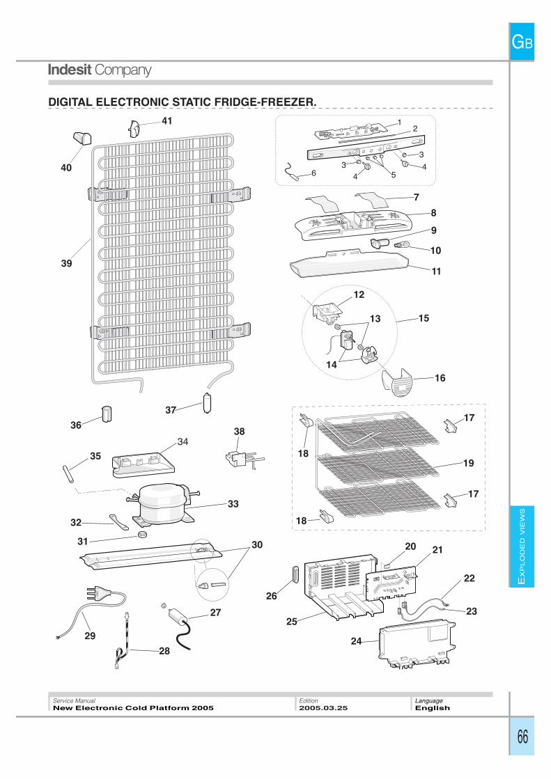
EX
PLO
DE
DV
IEW
S
GB
66
Service ManualNew Electronic Cold Platform 2005
Edition2005.03.25
LanguageEnglish
DIGITAL ELECTRONIC STATIC FRIDGE-FREEZER.
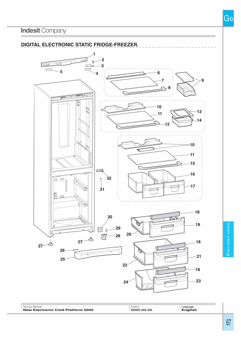
EX
PLO
DE
DV
IEW
S
GB
67
Service ManualNew Electronic Cold Platform 2005
Edition2005.03.25
LanguageEnglish
DIGITAL ELECTRONIC STATIC FRIDGE-FREEZER.
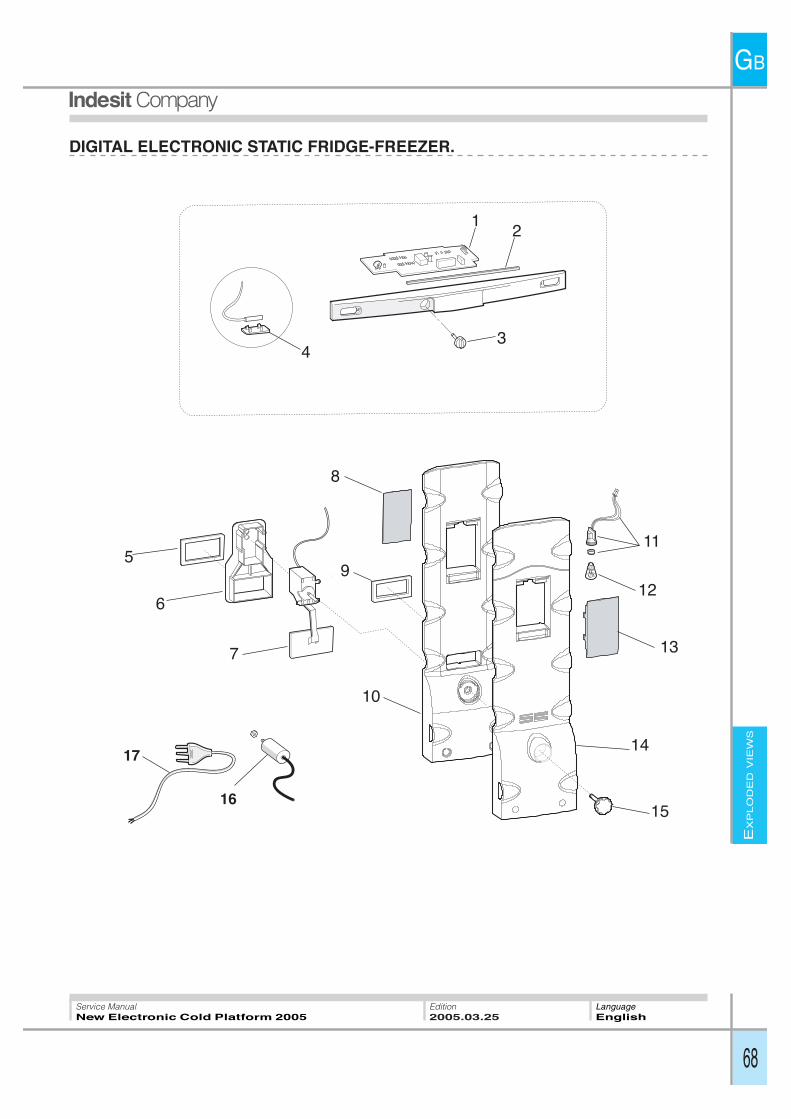
EX
PLO
DE
DV
IEW
S
GB
68
Service ManualNew Electronic Cold Platform 2005
Edition2005.03.25
LanguageEnglish
DIGITAL ELECTRONIC STATIC FRIDGE-FREEZER.
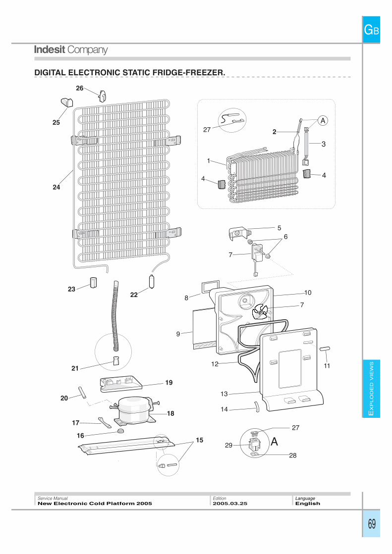
EX
PLO
DE
DV
IEW
S
GB
69
Service ManualNew Electronic Cold Platform 2005
Edition2005.03.25
LanguageEnglish
DIGITAL ELECTRONIC STATIC FRIDGE-FREEZER.
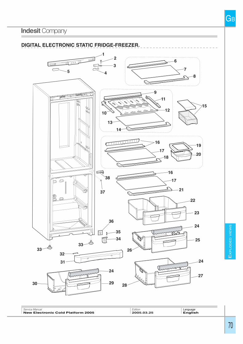
EX
PLO
DE
DV
IEW
S
GB
70
Service ManualNew Electronic Cold Platform 2005
Edition2005.03.25
LanguageEnglish
DIGITAL ELECTRONIC STATIC FRIDGE-FREEZER.

EX
PLO
DE
DV
IEW
S
GB
71
Service ManualNew Electronic Cold Platform 2005
Edition2005.03.25
LanguageEnglish
DIGITAL ELECTRONIC STATIC FRIDGE-FREEZER.
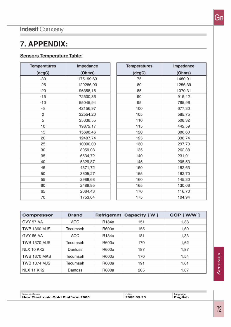
AP
PE
ND
IX
GB
72
Service ManualNew Electronic Cold Platform 2005
Edition2005.03.25
LanguageEnglish
Sensors Temperature Table:
7. APPENDIX:
Temperatures Impedance
(degC) (Ohms)-30 175199,63
-25 129286,93
-20 96358,16
-15 72500,36
-10 55045,94
-5 42156,97
0 32554,20
5 25338,55
10 19872,17
15 15698,46
20 12487,74
25 10000,00
30 8059,08
35 6534,72
40 5329,87
45 4371,72
50 3605,27
55 2988,68
60 2489,95
65 2084,43
70 1753,04
Temperatures Impedance
(degC) (Ohms)75 1480,91
80 1256,39
85 1070,31
90 915,42
95 785,96
100 677,30
105 585,75
110 508,32
115 442,59
120 386,60
125 338,74
130 297,70
135 262,38
140 231,91
145 205,53
150 182,63
155 162,70
160 145,30
165 130,06
170 116,70
175 104,94
Compressor Brand Refrigerant Capacity [ W ] COP [ W/W ]
GVY 57 AA ACC R134a 151 1,33
TWB 1360 MJS Tecumseh R600a 155 1,60
GVY 66 AA ACC R134a 181 1,33
TWB 1370 MJS Tecumseh R600a 170 1,62
NLX 10 KK2 Danfoss R600a 187 1,87
TWB 1370 MKS Tecumseh R600a 170 1,54
TWB 1374 MJS Tecumseh R600a 191 1,61
NLX 11 KK2 Danfoss R600a 205 1,87

GB
Indesit Companyviale Aristide Merloni, 4760044 Fabriano - Italytel. +39 0732 66 11 - telex 560196 - fax +39 0732 66 2954 - www.indesitcompany.com
Service ManualNew Electronic Cold Platform 2005
Edition2005.03.25
LanguageEnglish