Embed Size (px)
Citation preview

Freedom 1500 Elevator
ASME A17.1 Part V CSA B44.0
Nationwide Lifts, Inc.Revised: 03-2008
America’s choice for elevators.
Planning Guide

Table of Contents
Introduction 3
Planning for Freedom 1500 Installation 3
Description of Elevator Equipment 4
Hoistway and Cab Dimensions 6
Hoistway Construction 10
Guide Rail Backing Construction 11
Landing Door Opening Construction 12
Machine Room and Electrical Requirements 13
Elevator Control Panel and Pump Unit Specifications 14
Elevator Specifications for ASME A17.1 Part V Compliance 15
2
www.nwlifts.com 1-888-323-8755
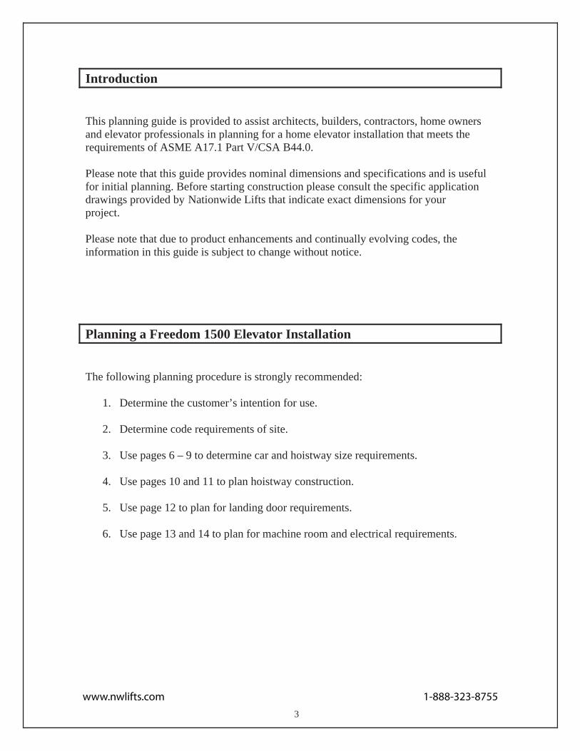
Introduction
This planning guide is provided to assist architects, builders, contractors, home owners and elevator professionals in planning for a home elevator installation that meets the requirements of ASME A17.1 Part V/CSA B44.0.
Please note that this guide provides nominal dimensions and specifications and is useful for initial planning. Before starting construction please consult the specific application drawings provided by Nationwide Lifts that indicate exact dimensions for your project.
Please note that due to product enhancements and continually evolving codes, the information in this guide is subject to change without notice.
Planning a Freedom 1500 Elevator Installation
The following planning procedure is strongly recommended:
1. Determine the customer’s intention for use.
2. Determine code requirements of site.
3. Use pages 6 – 9 to determine car and hoistway size requirements.
4. Use pages 10 and 11 to plan hoistway construction.
5. Use page 12 to plan for landing door requirements.
3
6. Use page 13 and 14 to plan for machine room and electrical requirements.
www.nwlifts.com 1-888-323-8755

Description of Elevator Equipment
General
Rated load: 1500 lb. Nominal speed: 40 feet per minuteMinimum pit depth: 10” (Heritage), 12” (Cambrian)Minimum overhead clearance: 108” Maximum travel: 50 feet Maximum number of stops: 6
Mechanical Equipment
208/230 VAC, 60 Hz, 40 Amp single phase power supply Dual 8 lb. modular T-rail systemTwo 3/8” diameter, 17 x 9 wire ropes Sling assemblyForged rope sockets 2:1 roped hydraulic single stage cylinder3.5 hp submersed pump with two-speed valve
Cab and Appointments
Cab floor sizes:40” x 48” 44” x 54” 44” x 60” Custom sizes available Cab height: 96” (custom height available) Four (4) recessed halogen cab lights Unfinished plywood walls (finishing by others) Unfinished plywood floor (finishing by others)
Gates and Doors
Swing door for each landing with automatic sliding cab doorAutomatic sliding door frames at each landing with automaticsliding cab door
4
Finishes available for sliding doors: Stainless steel or beige epoxy. Custom panels are also an option.
www.nwlifts.com 1-888-323-8755

Controls
Relay logic controller Fully automatic operationStainless steel car operating panel (COP), telephone box and hall call stationsAutomatic timed cab lighting Illuminated, position indicating push buttons on COPEmergency stop switch on COP
Safety Devices
Three (3) stainless steel handrails in cab (subject to cab configuration) 208/230 VAC lockable disconnect for power unit Final limitSlack rope safety switch Pit stop switch Car top stop switch Line rupture valve Low pressure switch Automatic releveling72” light beam safety curtain Emergency battery lowering, lighting and door opening Electromechanical door interlocks Manual lowering device Telephone in cab
Options
Custom cab sizes availablePre-finished oak, maple or cherry hardwood raised panel cab walls and ceiling Brass COP, telephone box and hall call stations Brass handrails Two piece hydraulic jack Handrail COP
5
LED/dot matrix Digital Position Indicator (DPI) on landing or within cab
www.nwlifts.com 1-888-323-8755
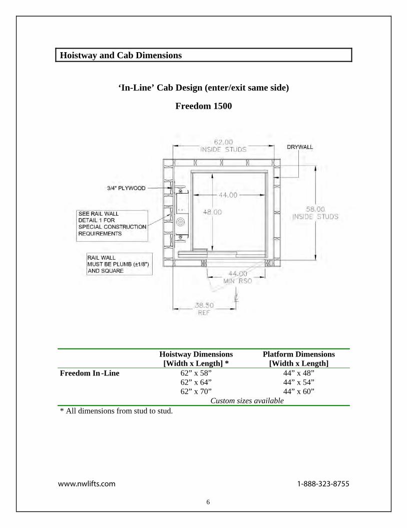
Hoistway and Cab Dimensions
‘In-Line’ Cab Design (enter/exit same side)
Freedom 1500
Hoistway Dimensions[Width x Length] *
Platform Dimensions [Width x Length]
Freedom In -Line 62” x 58” 44” x 48” 62” x 64” 44” x 54” 62” x 70” 44” x 60”
Custom sizes available* All dimensions from stud to stud.
6
www.nwlifts.com 1-888-323-8755

Hoistway and Cab Dimensions
‘In-line’ Cab Design (enter/exit same side)
Freedom 1500
Hoistway Dimensions[Width x Length]
Platform Dimensions [Width x Length]
Freedom In-Line 64” x 62” 44” x 48” 64” x 68” 44” x 54” 64” x 74” 44” x 60”
Custom sizes available* All dimensions from stud to stud.
7
www.nwlifts.com 1-888-323-8755

Hoistway and Cab Dimensions
‘Thru’ Cab Design (enter/exit opposite side)
Freedom 1500
Hoistway Dimensions[Width x Length]
Platform Dimensions [Width x Length]
Freedom Thru 62” x 59” 44” x 48” 62” x 65” 44” x 54” 62” x 71” 44” x 60”
Custom sizes available* All dimensions from stud to stud.
8
www.nwlifts.com 1-888-323-8755

Hoistway and Cab Dimensions
‘Thru’ Cab Design (enter/exit opposite side)
Freedom 1500
Hoistway Dimensions[Width x Length]
Platform Dimensions [Width x Length]
Freedom Thru 64” x 67” 44” x 48” 64” x 74” 44” x 54” 64” x 79” 44” x 60”
Custom sizes available
9
www.nwlifts.com 1-888-323-8755

Hoistway Construction
A load bearing wall is required to sustain rail reactions; please see Guide RailBacking Construction for detail.
Hoistway must be in accordance with ASME A17.1/CSA B44.0, as well as all local codes and regulations.
Pit floor construction must withstand a 5000 lb. load.
Due to limited clearances, it is necessary that hoistway walls be square and plumb. Maximum permissible deviation from hoistway top to bottom is 3/16”.
Building structure must sustain a chain hoist for hoisting elevator materials to the top of the hoistway during installation.
10
A structural engineer must ensure that building and hoistway can safely support all loads imposed by the elevator equipment.
www.nwlifts.com 1-888-323-8755

Guide Rail Backing Construction
Plan View of Hoistway
Wood studs to run the full height of the hoistway. Please consult the application drawing provided by Nationwide Lifts for exact placement of studs.
11
www.nwlifts.com 1-888-323-8755

Landing Door Opening Construction
12
Door Size A Dimension B Dimension 35 ½” x 78 ¾” 46” 86 ¾”
www.nwlifts.com 1-888-323-8755

Machine Room and Electrical Requirements
Machine room must be in accordance with all codes and regulations.
A 208/230 VAC, 60 Hz, 40 Amp single phase power source in the machine roomto be provided.
A telephone line circuit to be provided. This circuit must be connected to an outside line.
PLATFORM
HYDRAULIC LINE
JACKPOWER UNIT
CONTROLLER
A
Plan View of Machine Room
13
www.nwlifts.com 1-888-323-8755

Elevator Control Panel and Pump Unit Specifications
Elevator Control Panel
Hydraulic Power/Pump Unit
14
NATIONWIDE LIFTS
NATIONWIDE LIFTS
NATIONWIDE LIFTS
www.nwlifts.com 1-888-323-8755

Elevator Specifications for ASME A17.1 Part V Compliance
PART 1 – GENERAL
1.1 Product Description A private residence 2:1 roped hydraulic elevator.
1.2 Quality AssuranceThe elevator shall be designed, tested and installed in compliance with all applicableregulations and in accordance with ASME A17.1/CSA B44.0 standards. Elevator may be subject to state, local and city approval prior to installation and subject to inspection afterinstallation.
1.3 Applicable Codes and Standards
1.3.1 ASME A17.1/CSA B44.0, Private residence Elevators1.3.2 ASME A17.5/CSA B44.1, Elevator and Escalator Electrical Equipment1.3.3 ICC/ANSI A117.1-1998, Accessible and Usable Buildings and Facilities1.3.4 NFPA 70-1999, National Electric Code1.3.5 ADAAG, Americans with Disabilities Act Accessibility Guidelines
PART 2 – PREPARATORY WORK BY OTHERS
2.1 Hoistway Provide an enclosed, plumb and square hoistway with smooth interior surfaces. Providefascias or furring of hoistway interior where required.
2.2 Machine RoomProvide a machine room as required by applicable codes and standards.
2.3 Electrical Provide a 208/230 VAC, 60 Hz, 40 Amp single phase power source in the machine room.
PART 3 – SUBMITALS
3.1 Approval Drawings Approval drawings shall show a complete layout of elevator equipment, including plan and elevation views.
15
www.nwlifts.com 1-888-323-8755
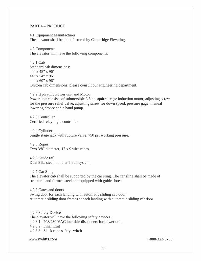
PART 4 – PRODUCT
4.1 Equipment Manufacturer The elevator shall be manufactured by Cambridge Elevating.
4.2 ComponentsThe elevator will have the following components.
4.2.1 Cab Standard cab dimensions:40” x 48” x 96” 44” x 54” x 96” 44” x 60” x 96” Custom cab dimensions: please consult our engineering department.
4.2.2 Hydraulic Power unit and Motor Power unit consists of submersible 3.5 hp squirrel-cage induction motor, adjusting screw for the pressure relief valve, adjusting screw for down speed, pressure gage, manuallowering device and a hand pump.
4.2.3 Controller Certified relay logic controller.
4.2.4 Cylinder Single stage jack with rupture valve, 750 psi working pressure.
4.2.5 Ropes Two 3/8” diameter, 17 x 9 wire ropes.
4.2.6 Guide rail Dual 8 lb. steel modular T-rail system.
4.2.7 Car Sling The elevator cab shall be supported by the car sling. The car sling shall be made of structural and formed steel and equipped with guide shoes.
4.2.8 Gates and doors Swing door for each landing with automatic sliding cab doorAutomatic sliding door frames at each landing with automatic sliding cab door
4.2.8 Safety Devices The elevator will have the following safety devices.4.2.8.1 208/230 VAC lockable disconnect for power unit 4.2.8.2 Final limit4.2.8.3 Slack rope safety switch
16
www.nwlifts.com 1-888-323-8755

4.2.8 Safety Devices (continued)
4.2.8.4 Pit stop switch4.2.8.5 Car top stop switch 4.2.8.6 Line rupture valve 4.2.8.7 Low pressure switch 4.2.8.8 Automatic releveling 4.2.8.9 72” light beam safety curtain 4.2.8.10 Emergency battery lowering and door opening 4.2.8.11 Electromechanical door interlocks 4.2.8.12 Manual lowering device 4.2.8.13 Handrail(s) inside cab
PART 5 – EXECUTION
5.1 ExaminationAll site dimensions shall be verified to ensure they meet specifications, codes and regulations.
5.2 Installation Elevator shall be installed by trained technicians in accordance with approved plans, specifications and manufacturer’s installation instructions.
5.3 Maintenance Elevator shall be maintained in accordance with the manufacturer’s instructions and all applicable codes.
5.4 WarrantyElevator shall carry twenty-four (24) month limited warranty on parts only.
17
www.nwlifts.com 1-888-323-8755