Embed Size (px)
Citation preview

Free-Body Diagram
Introduction
This tool guides you through a three-step process.
• You build trusses, frames, and machines by using drawing tools.
• You get the free-body diagrams (FBD) for the entire structure and its components.
• You get the strategy for the solution of the unknown, internal forces.
Start-up Window
When you open the tool, you will get the start-up window of Figure-1.
Figure-1: FBD start-up window.
The start-up window consists of six parts:
1. Top row pull-down menus.
2. Second row buttons.
3. Workspace.
4. Member-info grid at bottom left.
5. Node-info grid at bottom right.
6. Status bar at the bottom.

Mouse Operations
Click: clicking the left mouse button
Drag: moving the mouse while holding down the left mouse button.
Top row pull-down menus
File Menu: File handling operations – open saved files, save files, print, etc.
Graph Menu: Choices of workspace-background. Currently, the background is set at
“standard”.
View Menu: View or hide the “Member-info Grid” at bottom left, the “Node-info Grid” at
bottom right, and the “Status Bar” at the bottom.
Help Menu: Takes you to a website where you can watch a movie or download this help
manual.

Buttons
New File, Open File, Save File, Print Buttons:
Draw FBD Button:
After a structure is built, this button explodes the structure into its components and shows the
FBD of each component.
Figure-2: Draw FBD Button
Fit-to-Screen, Zoom-in, Zoom-out, Zoom Factor Buttons:
Scale and Units Buttons:
These two buttons work together. With the scale button, you can specify one square of the
background equals N number of units, where N = 1,5,10, etc. units.
With the unit button, you can set the length unit to meters, inches, etc.
Beams/Rods Buttons:
Figure-3: Beam/rod elements
These buttons create, from left to right, a straight, L-shaped, or T-shaped member. When you “Click”
on a beam/rod button, the cursor takes the shape of the member. “Click” anywhere in the workspace
and the beam/rod is drawn in the workspace as shown in Figure-4, below.

Figure-4: Straight, L-shaped, and T-shaped members.
When any member is inserted in the workspace, the data-grid at bottom left shows the properties of
the member, and the data-grid at bottom right shows the (x,y) coordinates of the end points (nodes) of
the member.
A member is stretched, deformed, and rotated by dragging the nodes (end-points) of the member. The
members of Figure-4 are changed into the members of Figure-5 by “dragging”.

Figure-5: Deformed members.
Examine Object Button:
The examine object button enables you to specify member dimensions and node locations. When you
“click” the “examine object” button and then “click” on any member in the workspace, you will get a
new window as shown in Figure-6. On this window you can edit/enter the length and angular
orientation of a member and you can specify the (x,y) coordinates of the end-points (nodes) of the
member.

Figure-6: Examine object and enter specific dimensions.
Joint Buttons:
Figure-7: Joints
These buttons are used to attach members with a pin-joint or a contact-joint.
A pin-joint can attach two or more overlapping members and can transfer only a reaction force
between the connected members. A fixed-joint can attach two overlapping nodes and can transfer a
reaction force and a reaction moment between the connected members.
When you “click” any joint button, the cursor takes the shape of the joint. You can then insert the joint
in the structure by “clicking” at a desired location, as shown in Figure-8.
Figure-8: Joined members.
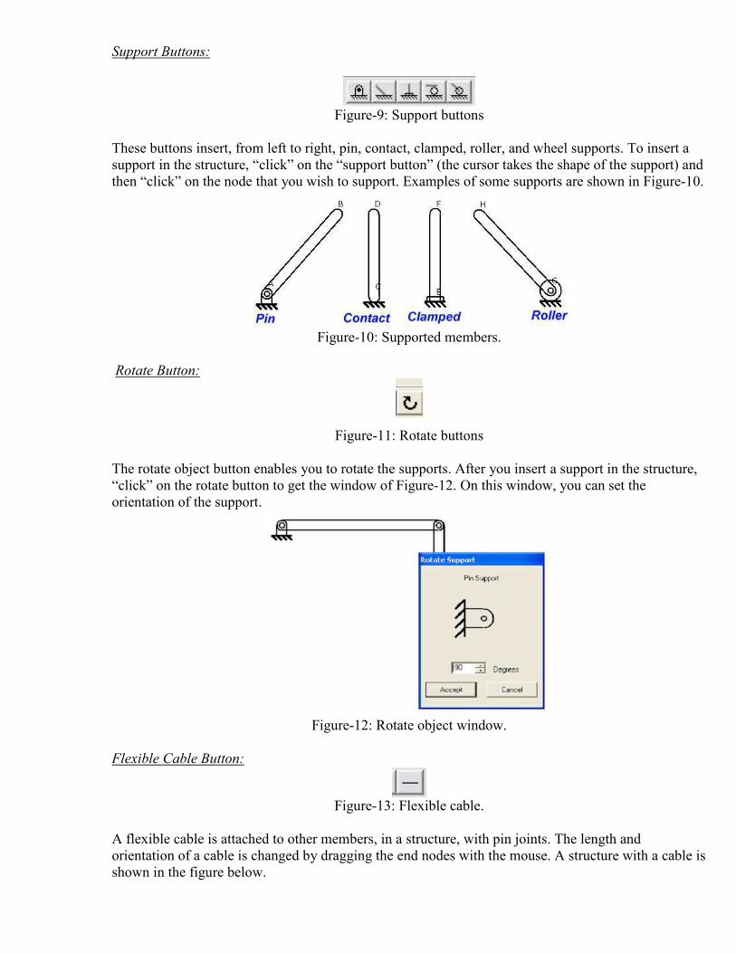
Support Buttons:
Figure-9: Support buttons
These buttons insert, from left to right, pin, contact, clamped, roller, and wheel supports. To insert a
support in the structure, “click” on the “support button” (the cursor takes the shape of the support) and
then “click” on the node that you wish to support. Examples of some supports are shown in Figure-10.
Figure-10: Supported members.
Rotate Button:
Figure-11: Rotate buttons
The rotate object button enables you to rotate the supports. After you insert a support in the structure,
“click” on the rotate button to get the window of Figure-12. On this window, you can set the
orientation of the support.
Figure-12: Rotate object window.
Flexible Cable Button:
Figure-13: Flexible cable.
A flexible cable is attached to other members, in a structure, with pin joints. The length and
orientation of a cable is changed by dragging the end nodes with the mouse. A structure with a cable is
shown in the figure below.
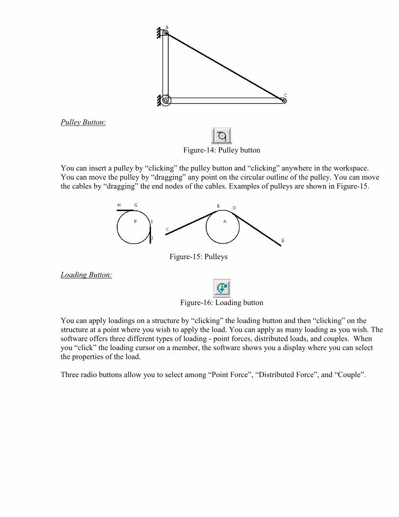
Pulley Button:
Figure-14: Pulley button
You can insert a pulley by “clicking” the pulley button and “clicking” anywhere in the workspace.
You can move the pulley by “dragging” any point on the circular outline of the pulley. You can move
the cables by “dragging” the end nodes of the cables. Examples of pulleys are shown in Figure-15.
Figure-15: Pulleys
Loading Button:
Figure-16: Loading button
You can apply loadings on a structure by “clicking” the loading button and then “clicking” on the
structure at a point where you wish to apply the load. You can apply as many loading as you wish. The
software offers three different types of loading - point forces, distributed loads, and couples. When
you “click” the loading cursor on a member, the software shows you a display where you can select
the properties of the load.
Three radio buttons allow you to select among “Point Force”, “Distributed Force”, and “Couple”.

Point Force:
In the window of Figure-17, the point force has a magnitude of 2000 units, makes an angle of 60
degrees with the horizontal direction, and is at a distance of 12 units from node-B and 8 units from
node-A.
Figure-17: Point force specifications

Distributed Force:
In the window of Figure-18, the distributed is selected as linear; the span of this distributed force is
defined by the distances of 4 units from node-A and 6 units from node-B. The starting and ending
magnitudes of this ramp load are entered as 2000 and 50 units. The loading makes an angle of 270
degrees with the member.
Figure-18: Distributed force specifications
Couple:
In the window of Figure-19, the couple has a magnitude of 3000 units, is chosen to be counter-clock-
wise, and is at a distance of 8 units from node-B and 12 units from node-A
Figure-19: Couple specifications
Delete Button:
Figure-20: Delete button
By suing this button, you can delete any structural member or loading from the workspace. To remove
an item, “click” the delete button and then put the delete cursor on an item that you wish to delete and
“click”.
Example-1: Unsolvable Structures
There are two kinds of unsolvable truss/frame/machine analysis problems: (i) Problems for
which the number of equilibrium equations exceeds the number of internal and support forces.
These structures are usually collapsible or non-rigid. (ii) Problems for which the number of
equilibrium equations is less than the number of internal and support forces. These problems
are called indeterminate problems and usually require principles of mechanics of materials.
This software can identify unsolvable problems and displays an error message.
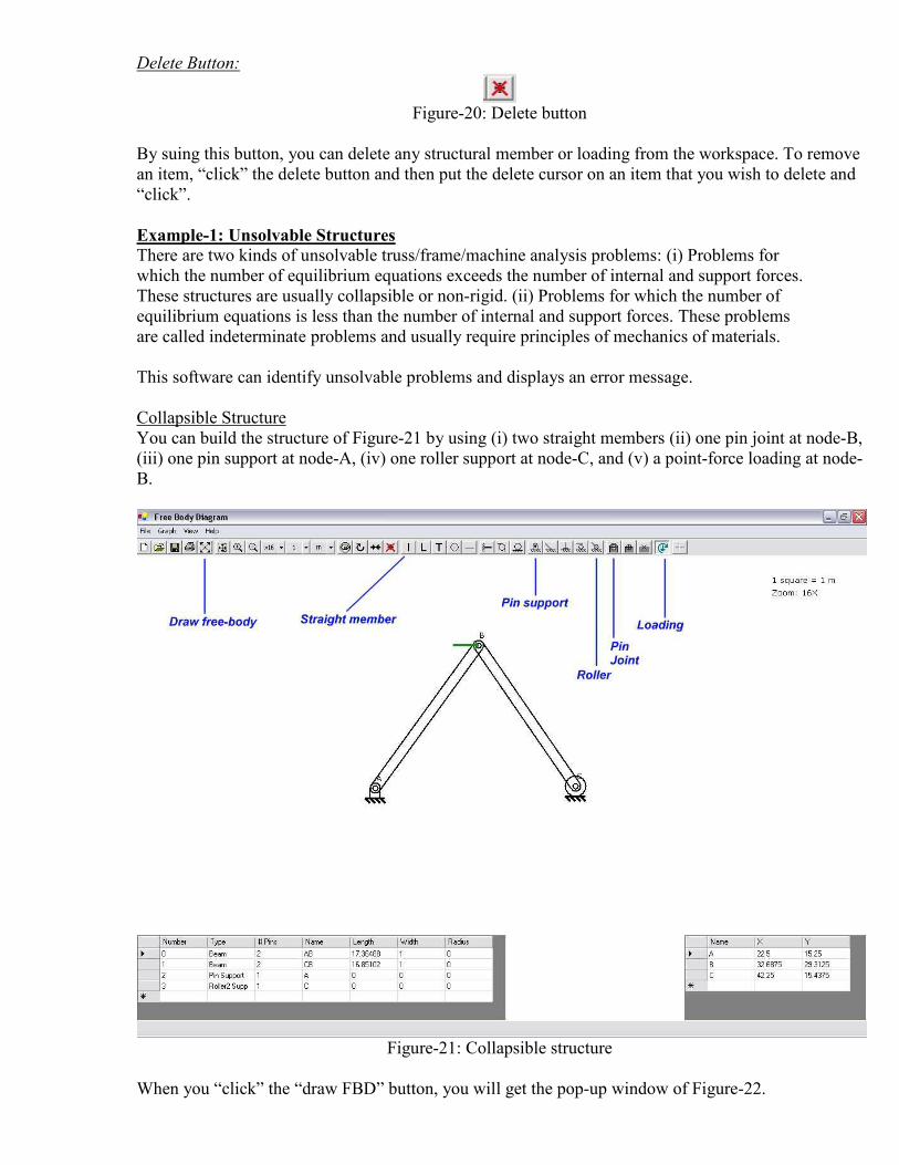
Collapsible Structure
You can build the structure of Figure-21 by using (i) two straight members (ii) one pin joint at node-B,
(iii) one pin support at node-A, (iv) one roller support at node-C, and (v) a point-force loading at node-
B.
Figure-21: Collapsible structure
When you “click” the “draw FBD” button, you will get the pop-up window of Figure-22.

Figure-22: Over-determined/Collapsible structure error.
Indeterminate Structure
You can build the structure of Figure-23 by using (i) three straight members (ii) three pin joints at
nodes-A,B,C, (iii) two pin supports at node-A,C, and (iv) a point-force loading at node-B.
Figure-23: Indeterminate structure
When you left-click the “draw FBD” button, you will get the pop-up window of Figure-24.
Figure-24: Indeterminate structure error.

Example-2: The A-Frame
You can build the structure of Figure-25 by using (i) three straight members (ii) three pin joints at
nodes-A,B, and C, (iii) one pin support at node-A and a roller support at C. Then two point forces and
a couple are added as the loading on the frame.
Figure-25: Loaded A-Frame
To calculate the loading on each of the three members, and the loading on the pins, one must draw the
FBD for the whole body and each component. To draw the FBD, “click” the “draw FBD” button to
get the screen of Figure-26, showing the FBD of the whole frame, with support reactions shown with
purple arrows.
Free-Body Diagrams
At the top, left-hand corner of this window, you will find a number of tabs, as shown in Figure-27.
§ The first tab is for the FBD of the whole frame.
§ The second tab is where you can plan the solution strategy for this problem.
§ The subsequent tabs show the FBD’s of all the members and pins in the structure.
Also, at the top left-hand corner of the workspace, the software tells you that for the FBD of the whole
frame, you can write three equilibrium equations and the FBD contains three unknown support forces
from the pin supports.

Figure-26: FBD of A-Frame.
Figure-27: FBD Tabs for Components
In Figures- 28, 29, 30, and 31 the FBD’s of the members and the pins are shown.

Figure-28: FBD of member ABE

Figure-29: FBD of member CBD

Figure-30: FBD of member DE

Figure-31: FBD of pins A, B, C, D.
All the internal, reaction forces are shown in purple, and the applied loadings are shown in green. The
software automatically labels the internal, reaction forces. To see the node labels on a member, place
the cursor on the member, as shown in Figure-32. To see a force-label, place the cursor on the force,
as shown in Figure-33.

Figure-32: View node labels by placing the cursor on a member.

Figure-33: View the force labels by placing the cursor on a purple arrow.
Solution Strategy
To devise a plan for the calculation of all the internal, reaction forces, “click” on the tab labeled
“Solution Strategy”. On the pop-up window, click “Yes” if you wanted to develop your own “solution
strategy”; if you wanted the software to devise the “solution strategy” for you, click “No”. If you had
clicked “Yes”, you will get the window of Figure-34.
On the left-hand-side of this window, you will get a list of FBD’s; on the right-hand-side a solution
panel. To analyze a FBD:
1. Select a FBD by “clicking” on it in the list of FBD’s.
2. Click the “Add” button.
3. Click the “Solve” button.

Figure-34: Solution strategy for A-frame.
In Figure-35, we have selected the “Whole FBD” from the list, clicked the “Add” button, and clicked
the “Solve” button. When the chosen FBD is solvable, we get the message – “Partial Solution
Successful”.

Figure-35: Analyzing the “Whole FBD”
Next, in Figure-36, we have selected “Member ABE” from the list, clicked the “Add” button, and
clicked the “Solve” button. When the chosen FBD is not solvable, we get the message – “cannot be
solved because there are too many unknowns”.

Figure-36: Analyzing Member ABE.
Unsolvable FBD’s should be removed from the solution pane.
1. Select a FBD by clicking on it in the solution pane.
2. Click the “remove” button.
In this manner, you can develop the strategy for solving all the FBD’s.
1. “Add” an FBD to the solution pane.
2. Click “Solve”
3. Keep the chosen FBD in the solution pane when it is solvable.
4. “Remove” the chosen FBD from the solution pane when it is not solvable.
5. “Add” another FBD in the solution pane.
6. Continue process until all FBD’s are solved.
7. You can always take the easy way out by clicking the “Salvage” button and let the software
complete the solution, as shown in Figure-37.

Figure-37: Allowing the software to complete solution by using the “Salvage” button.
In Figure-37, you will notice that the third, fourth, and fifth rows are all numbered as Step-3. This
means that the FBD’s for Member-CBD, Member-DE, and Pin-D cannot be solved one at a time, but
should be solved simultaneously.
Example-3: Two-force Members
Identification of two-force members is a skill that you must have. If you cannot identify two-
force members, you will unnecessarily lengthen the solution procedure. We all know that a
member of any shape is two-force when only two forces act on it. The software has the ability
to identify two-force members, even when the members have a complex shape. Consider the
A-frame in Figure-38 containing a non-straight, two-force member.

Figure-38: A-frame with odd-shaped two-force member.
The software can identify the Member EDFG as two-force, as shown in Figure-39.

Figure-39: Non-straight, two-force member.
Example-4: Frame with a Pulley
In this example, we will build a frame with a pulley. In Figure-40, a part of the frame is built
and a pulley is added in the workspace.

Figure-40: Step-1 of frame with pulley.
In the next step, we move the pulley on the node B and attach it with a pin-joint, as shown in
Figure-41. To move the pulley, we “drag” the circular outline of the pulley.

Figure-41: Step-2 of frame with pulley.
Next, we “drag” the end nodes of the two cables and align these as shown in Figure-42.

Figure-42: Step-3 of frame with pulley.
Next, we join the end of the left cable with a member, pin the two members, and apply a load
at the end of the other cable, as shown in Figure-43.

Figure-43: Step-4 of frame with pulley.
In Figures-44, 45, 46, and 47, a few FBD’s for this problem and the solution strategy, as
determined by the software, are shown.

Figure-44: Whole FBD of frame with pulley.

Figure-45: FBD of a member of frame with pulley.

Figure-46: FBD of a member of frame with pulley.

Figure-47: Solution strategy for frame with pulley.
Example-5: Frame with load applied at pin-joints
Often, students find it difficult to draw FBD’s for a class of problems where point loads are
applied at the pin joints of a frame. Such a frame is shown in Figure-48 with point forces on
pins B and F.

Figure-48: Loaded pin joints.
For the loaded pin joints, at B and F, students cannot decide where to include the load at the joint – in
the FBD of one of the members, or in the FBD’s of all of the members connected at that joint, or in the
FBD of the pin at the joint? The answer is actually quite simple – you can insert the load in any FBD
you wish, but remember that the load is included “ONLY ONCE” and only in “ONE” FBD. This
software works with a uniform strategy of adding the applied load in the FBD of the pin at the joint
and not on any member. This is a strategy you are familiar with when you solved truss problems by
using the method of joints.
The FBD’s for the problem of Figure-48 are shown in Figure-49.

Figure-49: FBD’s for frame problem with loaded pin joints.
Example-6: Machine
To analyze machines like the one shown in Figure-50, you need to build the machine in its skeletal
form.
Figure-50: Machine
First, we build the upper jaw by using two straight members and a fixed joint, as shown in Figure-51.

Figure-51: Upper jaw of machine
Next, we build the lower jaw with three straight members and two fixed joints, as shown in Figure-52.
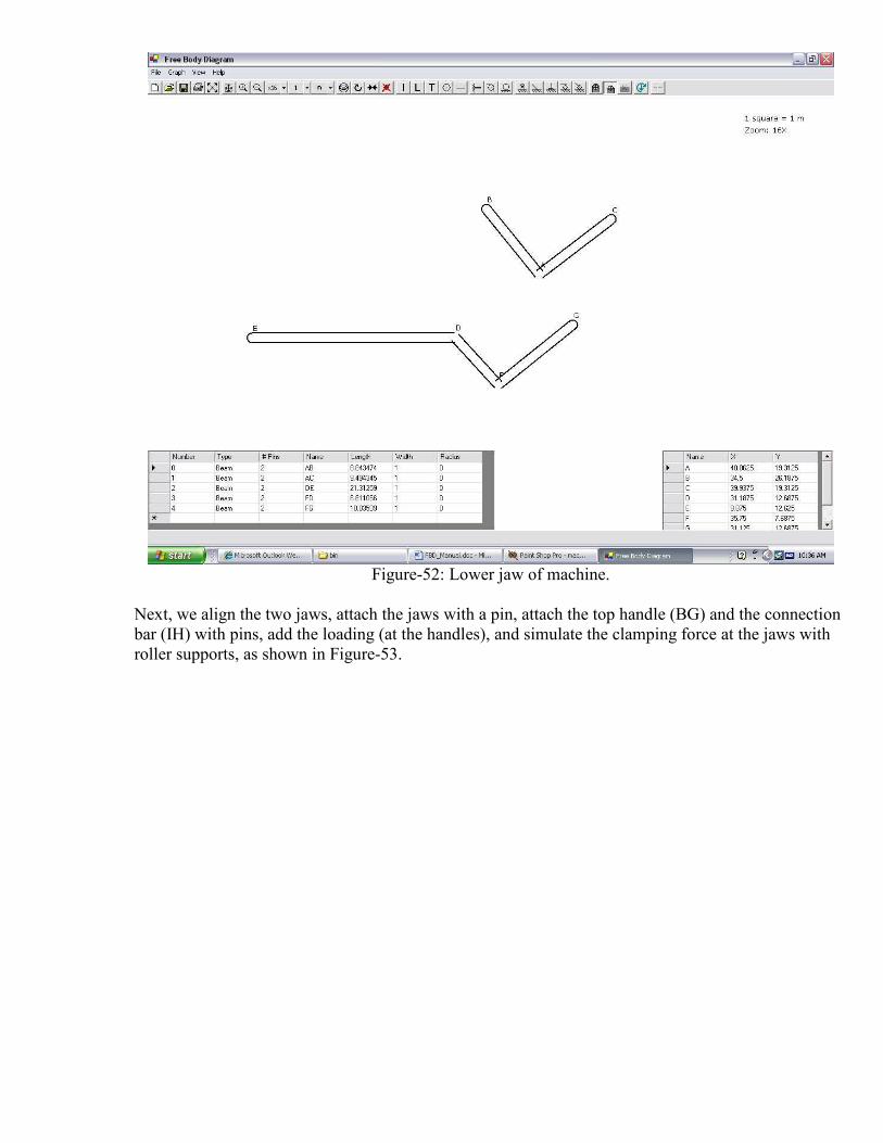
Figure-52: Lower jaw of machine.
Next, we align the two jaws, attach the jaws with a pin, attach the top handle (BG) and the connection
bar (IH) with pins, add the loading (at the handles), and simulate the clamping force at the jaws with
roller supports, as shown in Figure-53.

Figure-53: Skeletal construction of a machine.
When you click the “draw FBD” button, the software responds with the message of Figure-54,
because the whole machine is not in equilibrium when the two forces at nodes D and G are unequal.
Figure-54: Error message for machine.
However, this does not stop you from viewing the FBD’s of the components of the machine. These
FBD’s are shown in Figure-55.
(a) Lower jaw

(b) Upper jaw
(c) Top handle
(d) Connecting rod.
Figure-55: FBD’s of the components of the machine.
The solution strategy for the FBD’s, as determined by the software, is shown in Figure-56.
Figure-56: Solution strategy for the machine.