Embed Size (px)
Citation preview

State of California AIR RESOURCES BOARD
Executive Order VR-103-F
Franklin Fueling Systems, Inc
EBW Phase I Vapor Recovery System WHEREAS, the California Air Resources Board (ARB) has established, pursuant to California Health and Safety Code sections 25290.1.2, 39600, 39601 and 41954, certification procedures for systems designed for the control of gasoline vapor emissions during the filling of underground gasoline storage tanks, in its CP-201, Certification Procedure for Vapor Recovery Systems at Gasoline Dispensing Facilities (Certification Procedure) as last amended May 25, 2006, incorporated by reference in title 17, California Code of Regulations, section 94011; WHEREAS, ARB has established, pursuant to California Health and Safety Code sections 39600, 39601 and 41954, test procedures for determining the compliance of Phase I vapor recovery systems with emission standards; WHEREAS, Franklin Fueling Systems, Inc. (FFS) requested and was granted certification of the EBW Phase I Vapor Recovery System (EBW system) pursuant to the Certification Procedure on September 26, 2003 by Executive Order VR-103-A, and last modified on September 14, 2009 by Executive Order VR-103-E; WHEREAS, the EBW system certification expires on May 31, 2012; WHEREAS, the Certification Procedure authorizes the Executive Officer or Executive Officer delegate to extend the certification of the EBW system when more time is needed to gather necessary information to complete a renewal evaluation; WHEREAS, the Certification Procedure provides that the ARB Executive Officer shall issue an Executive Order if he or she determines that the vapor recovery system, including modifications, conforms to all of the applicable requirements set forth in the Certification Procedure; WHEREAS, G-01-032 delegates to the Chief of the Monitoring and Laboratory Division the authority to certify or approve modifications to certified Phase I and Phase II vapor recovery systems for gasoline dispensing facilities (GDF); and WHEREAS, I, Alberto Ayala, Chief of the Monitoring and Laboratory Division, find that the EBW Phase I Vapor Recovery System conforms with all the requirements set forth in the Certification Procedure and results in a vapor recovery system which is at least 98.0 percent efficient as tested pursuant to the test procedure TP-201.1, Volumetric Efficiency for Phase I Systems (October 8, 2003);

-2-
Executive Order VR-103-F, EBW Phase I Vapor Recovery System
NOW THEREFORE, IT IS HEREBY ORDERED that the EBW system is certified to be at least 98.0 percent efficient when installed and maintained as specified herein and in the following Exhibits. Exhibit 1 contains a list of the certified components. Exhibit 2 contains the performance standards and specifications, typical installation drawings and maintenance intervals applicable to the EBW system as installed in a gasoline dispensing facility (GDF). Exhibit 3 contains the manufacturing specifications. IT IS FURTHER ORDERED that compliance with the applicable certification requirements, rules and regulations of the Division of Measurement Standards of the Department of Food and Agriculture, the Office of the State Fire Marshal of the Department of Forestry and Fire Protection, the Division of Occupational Safety and Health of the Department of Industrial Relations, and the Division of Water Quality of the State Water Resources Control Board are made conditions of this certification. IT IS FURTHER ORDERED that FFS shall provide a warranty for the vapor recovery system and components to the initial purchaser and each subsequent purchaser within the warranty period. The manufacturer of components not manufactured by FFS shall provide a warranty for each of their components certified herein. This warranty shall include the ongoing compliance with all applicable performance standards and specifications and shall comply with all warranty requirements in Section 16.5 of the Certification Procedure. FFS or other manufacturers may specify that the warranty is contingent upon the use of trained installers. IT IS FURTHER ORDERED that the certified EBW system shall be installed and maintained in accordance with the ARB Approved Installation, Operation and Maintenance Manual for the EBW Phase I Vapor Recovery System as certified by Executive Order VR-103-F. A copy of this Executive Order and manual shall be maintained at each GDF where a certified EBW system is installed. IT IS FURTHER ORDERED that equipment listed in Exhibit 1, unless exempted, shall be clearly identified by a permanent identification showing the manufacturer’s name and model number. IT IS FURTHER ORDERED that any alteration in the equipment parts, design, installation or operation of the system certified hereby is prohibited and deemed inconsistent with this certification unless the alteration has been submitted in writing and approved in writing by the Executive Officer or Executive Officer delegate. IT IS FURTHER ORDERED that the following requirements are made a condition of certification. The owner or operator of the EBW system shall conduct, and pass, the following tests no later than 60 days after startup and at least once every 3 years after startup testing, using the latest adopted version of the following test procedures: TP-201.3, Determination of 2 Inch WC Static Pressure Performance of Vapor Recovery Systems of Dispensing Facilities (March 17, 1999), and TP-201.1B, Static Torque of Rotatable Phase I Adaptors (October 8, 2003); and depending upon the system configuration, either TP-201.1D, Pressure Integrity of Drop Tube Overfill Prevention Devices (October 8, 2003); or TP-201.1C, Pressure Integrity of Drop Tube/Drain Valve Assembly (October 8, 2003). Shorter time periods may be
Executive Order VR-103-F, EBW Phase I Vapor Recovery System, Exhibit 1 Page 1
Executive Order VR-103-F EBW Phase I Vapor Recovery System
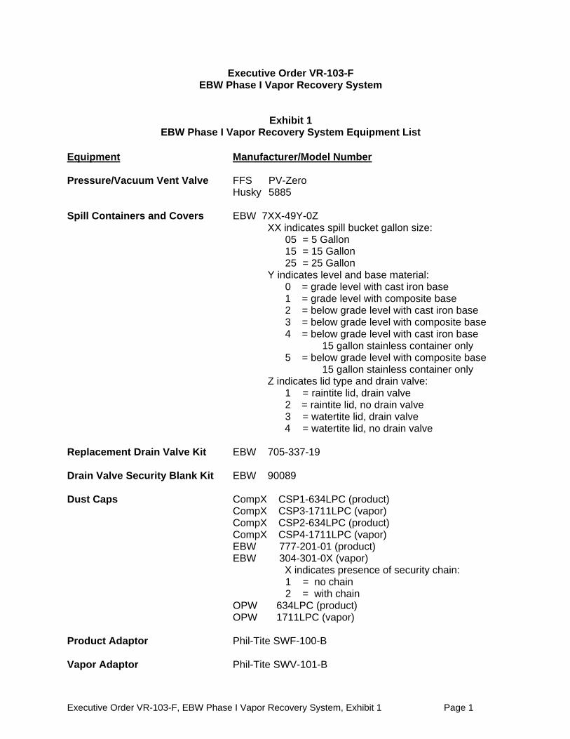
Exhibit 1 EBW Phase I Vapor Recovery System Equipment List
Equipment Manufacturer/Model Number Pressure/Vacuum Vent Valve FFS PV-Zero Husky 5885 Spill Containers and Covers EBW 7XX-49Y-0Z
XX indicates spill bucket gallon size: 05 = 5 Gallon 15 = 15 Gallon 25 = 25 Gallon
Y indicates level and base material: 0 = grade level with cast iron base 1 = grade level with composite base 2 = below grade level with cast iron base 3 = below grade level with composite base 4 = below grade level with cast iron base
15 gallon stainless container only 5 = below grade level with composite base
15 gallon stainless container only Z indicates lid type and drain valve:
1 = raintite lid, drain valve 2 = raintite lid, no drain valve 3 = watertite lid, drain valve 4 = watertite lid, no drain valve
Replacement Drain Valve Kit EBW 705-337-19 Drain Valve Security Blank Kit EBW 90089 Dust Caps CompX CSP1-634LPC (product) CompX CSP3-1711LPC (vapor) CompX CSP2-634LPC (product) CompX CSP4-1711LPC (vapor) EBW 777-201-01 (product) EBW 304-301-0X (vapor) X indicates presence of security chain:
1 = no chain 2 = with chain
OPW 634LPC (product) OPW 1711LPC (vapor) Product Adaptor Phil-Tite SWF-100-B Vapor Adaptor Phil-Tite SWV-101-B
Executive Order VR-103-F, EBW Phase I Vapor Recovery System, Exhibit 1 Page 2
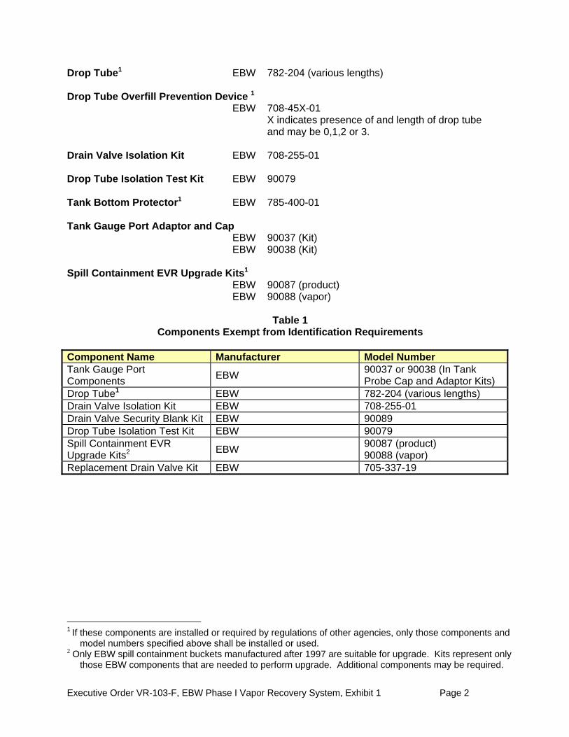
Drop Tube1 EBW 782-204 (various lengths) Drop Tube Overfill Prevention Device 1 EBW 708-45X-01 X indicates presence of and length of drop tube and may be 0,1,2 or 3. Drain Valve Isolation Kit EBW 708-255-01 Drop Tube Isolation Test Kit EBW 90079 Tank Bottom Protector1 EBW 785-400-01 Tank Gauge Port Adaptor and Cap EBW 90037 (Kit) EBW 90038 (Kit) Spill Containment EVR Upgrade Kits1 EBW 90087 (product) EBW 90088 (vapor)
Table 1
Components Exempt from Identification Requirements Component Name Manufacturer Model Number Tank Gauge Port Components
EBW 90037 or 90038 (In Tank Probe Cap and Adaptor Kits)
Drop Tube1 EBW 782-204 (various lengths) Drain Valve Isolation Kit EBW 708-255-01 Drain Valve Security Blank Kit EBW 90089 Drop Tube Isolation Test Kit EBW 90079 Spill Containment EVR Upgrade Kits2
EBW 90087 (product) 90088 (vapor)
Replacement Drain Valve Kit EBW 705-337-19
1 If these components are installed or required by regulations of other agencies, only those components and model numbers specified above shall be installed or used. 2 Only EBW spill containment buckets manufactured after 1997 are suitable for upgrade. Kits represent only those EBW components that are needed to perform upgrade. Additional components may be required.
Executive Order VR-103-F, EBW Phase I Vapor Recovery System, Exhibit 1 Page 3
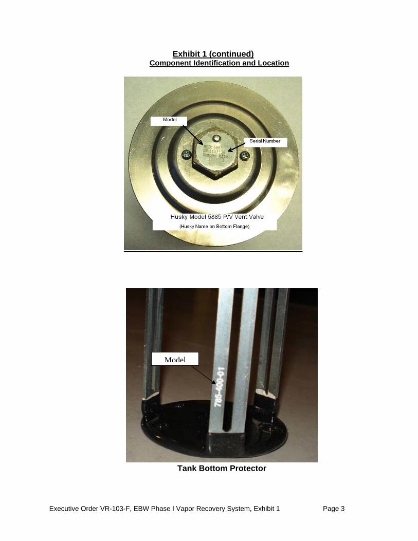
Exhibit 1 (continued) Component Identification and Location
Tank Bottom Protector
Model
Executive Order VR-103-F, EBW Phase I Vapor Recovery System, Exhibit 1 Page 4
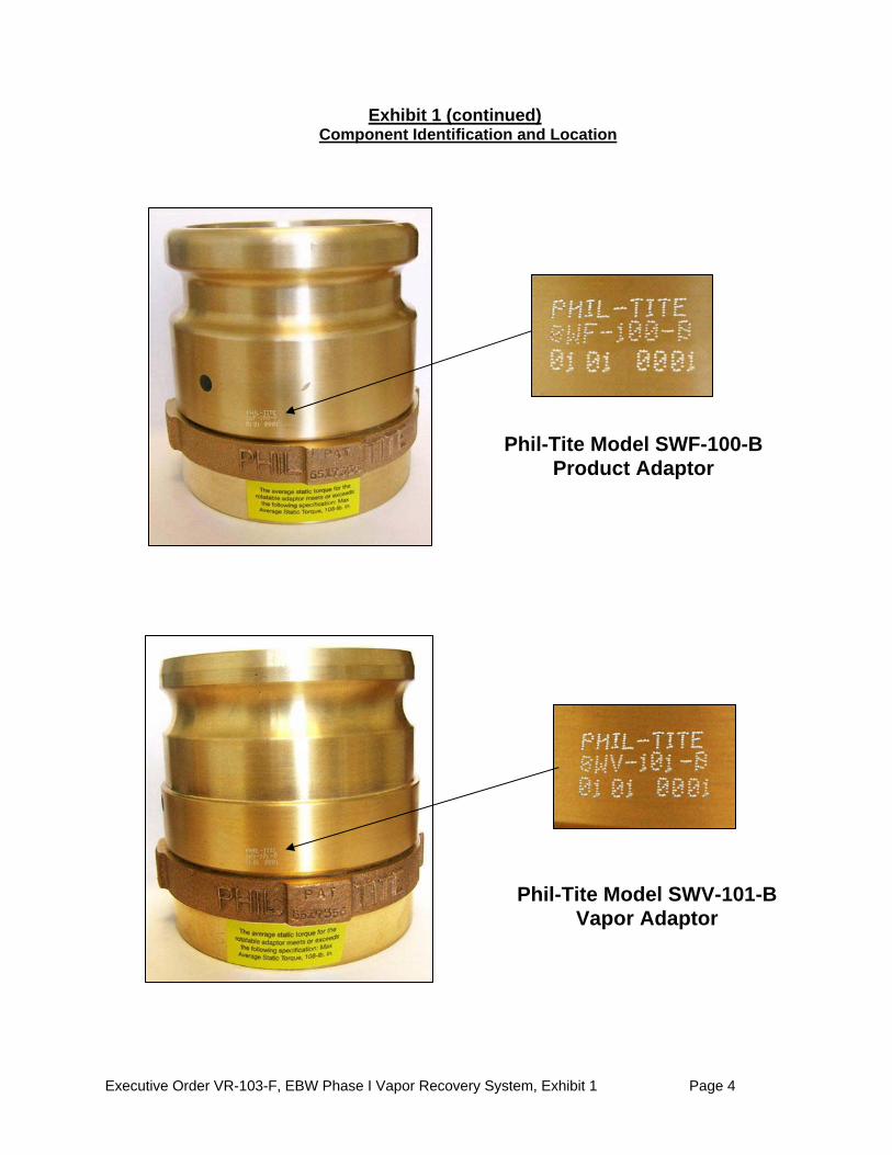
Exhibit 1 (continued) Component Identification and Location
Phil-Tite Model SWF-100-B Product Adaptor
Phil-Tite Model SWV-101-B Vapor Adaptor
Executive Order VR-103-F, EBW Phase I Vapor Recovery System, Exhibit 1 Page 5
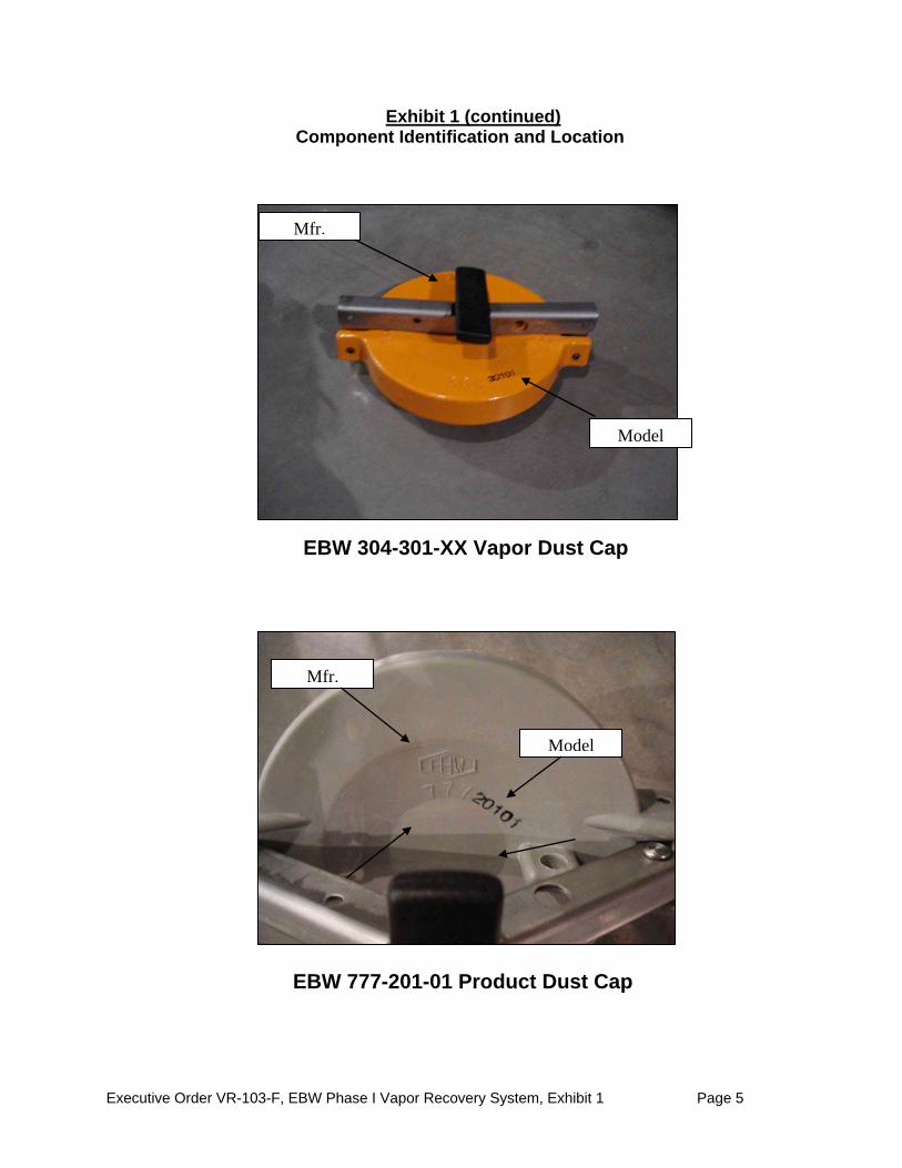
EBW 304-301-XX Vapor Dust Cap
Model
Mfr.
Exhibit 1 (continued) Component Identification and Location
EBW 777-201-01 Product Dust Cap
Model
Mfr.
Executive Order VR-103-F, EBW Phase I Vapor Recovery System, Exhibit 1 Page 6
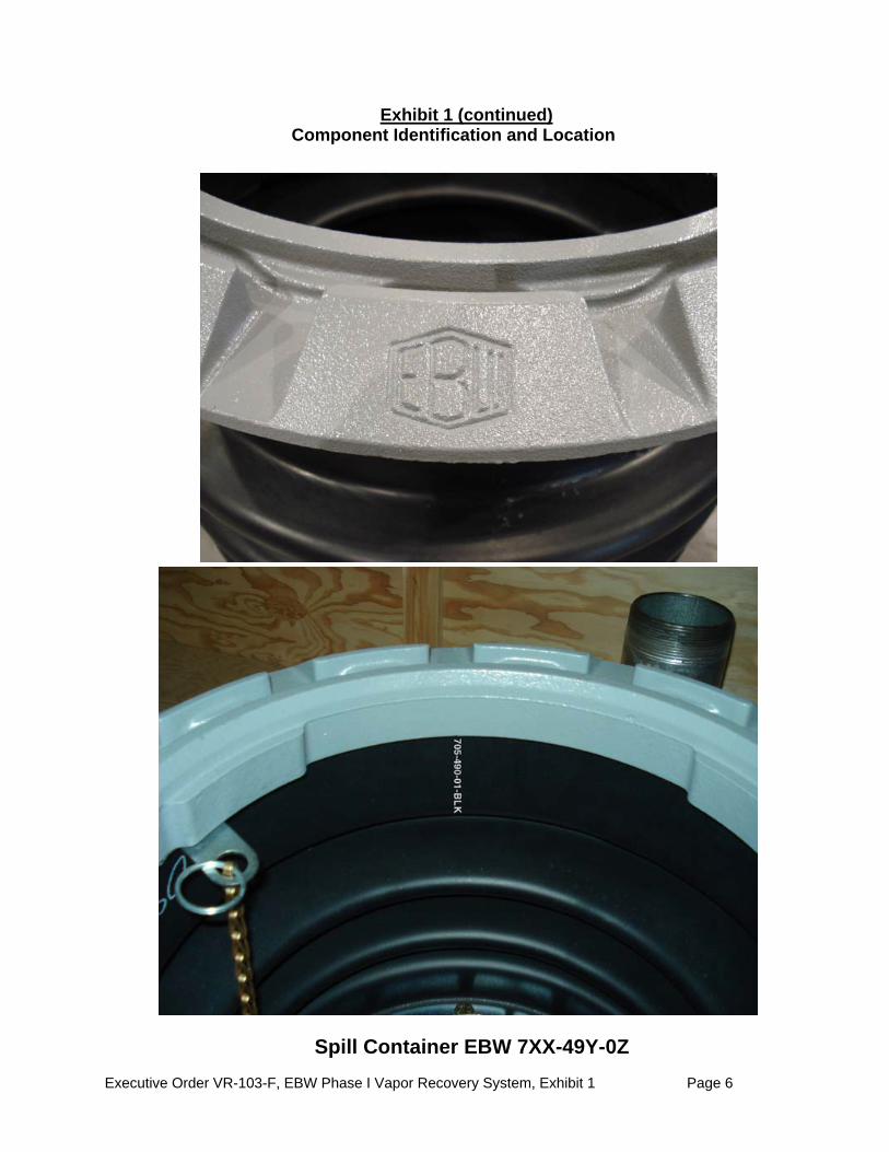
Exhibit 1 (continued) Component Identification and Location
Typical example of model numbering for Spill Container
EBW 7XX-49Y-0Z
Mfr.
Spill Container EBW 7XX-49Y-0Z

Executive Order VR-103-F, EBW Phase I Vapor Recovery System, Exhibit 1 Page 7
Exhibit 1 (continued) Component Identification and Location
Drop Tube Overfill Prevention Device EBW 708-45X-01
(Examples of four sizes)

Executive Order VR-103-F, EBW Phase I Vapor Recovery System, Exhibit 1 Page 8
Exhibit 1 (continued) Component Identification and Location
FFS PV-Zero P/V Vent Valve (Model and Serial Number on White Tag)
Executive Order VR-103-F, EBW Phase I Vapor Recovery System, Exhibit 1 Page 9
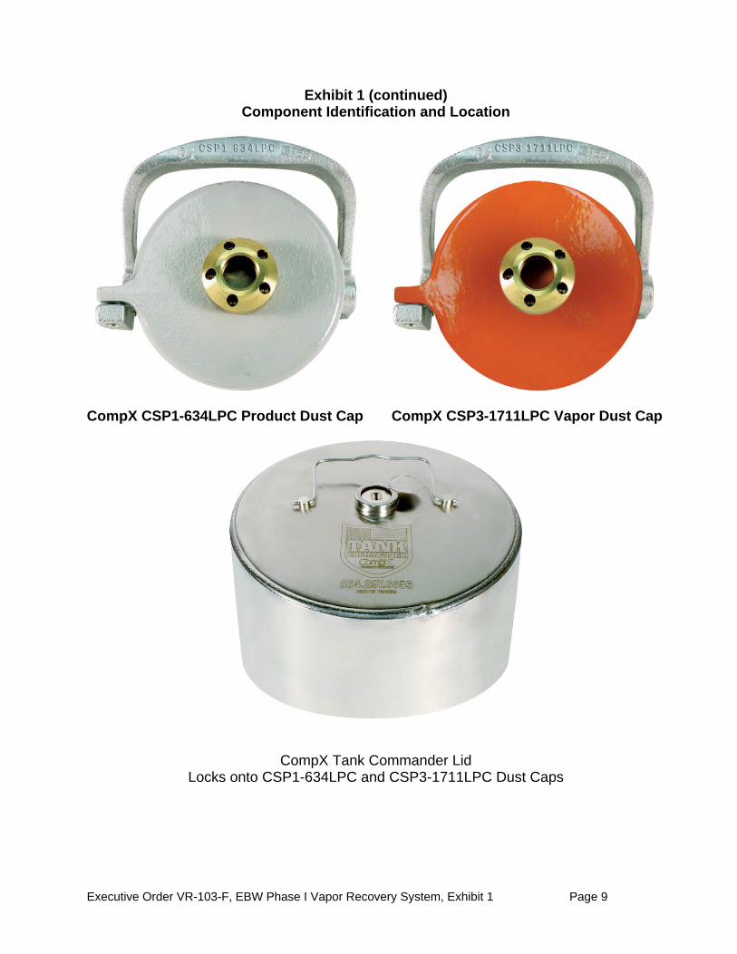
Exhibit 1 (continued) Component Identification and Location
CompX CSP1-634LPC Product Dust Cap CompX CSP3-1711LPC Vapor Dust Cap
CompX Tank Commander Lid Locks onto CSP1-634LPC and CSP3-1711LPC Dust Caps
Executive Order VR-103-F, EBW Phase I Vapor Recovery System, Exhibit 1 Page 10
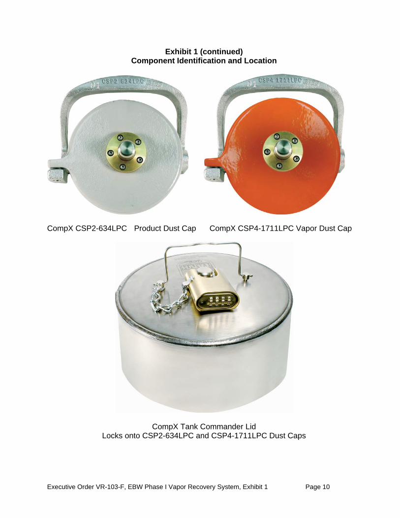
Exhibit 1 (continued) Component Identification and Location
CompX CSP2-634LPC Product Dust Cap CompX CSP4-1711LPC Vapor Dust Cap
CompX Tank Commander Lid Locks onto CSP2-634LPC and CSP4-1711LPC Dust Caps

Executive Order VR-103-F, EBW Phase I Vapor Recovery System, Exhibit 1 Page 11
Exhibit 1 (continued) Component Identification and Location
Executive Order VR-103-F, EBW Phase I Vapor Recovery System, Exhibit 2 Page 1
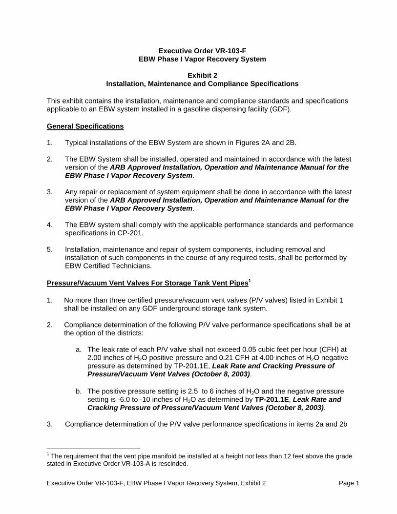
Executive Order VR-103-F EBW Phase I Vapor Recovery System
Exhibit 2
Installation, Maintenance and Compliance Specifications
This exhibit contains the installation, maintenance and compliance standards and specifications applicable to an EBW system installed in a gasoline dispensing facility (GDF). General Specifications 1. Typical installations of the EBW System are shown in Figures 2A and 2B. 2. The EBW System shall be installed, operated and maintained in accordance with the latest
version of the ARB Approved Installation, Operation and Maintenance Manual for the EBW Phase I Vapor Recovery System.
3. Any repair or replacement of system equipment shall be done in accordance with the latest
version of the ARB Approved Installation, Operation and Maintenance Manual for the EBW Phase I Vapor Recovery System.
4. The EBW system shall comply with the applicable performance standards and performance
specifications in CP-201. 5. Installation, maintenance and repair of system components, including removal and
installation of such components in the course of any required tests, shall be performed by EBW Certified Technicians.
Pressure/Vacuum Vent Valves For Storage Tank Vent Pipes1 1. No more than three certified pressure/vacuum vent valves (P/V valves) listed in Exhibit 1
shall be installed on any GDF underground storage tank system. 2. Compliance determination of the following P/V valve performance specifications shall be at
the option of the districts:
a. The leak rate of each P/V valve shall not exceed 0.05 cubic feet per hour (CFH) at 2.00 inches of H2O positive pressure and 0.21 CFH at 4.00 inches of H2O negative pressure as determined by TP-201.1E, Leak Rate and Cracking Pressure of Pressure/Vacuum Vent Valves (October 8, 2003).
b. The positive pressure setting is 2.5 to 6 inches of H2O and the negative pressure
setting is -6.0 to -10 inches of H2O as determined by TP-201.1E, Leak Rate and Cracking Pressure of Pressure/Vacuum Vent Valves (October 8, 2003).
3. Compliance determination of the P/V valve performance specifications in items 2a and 2b
1 The requirement that the vent pipe manifold be installed at a height not less than 12 feet above the grade stated in Executive Order VR-103-A is rescinded.

Executive Order VR-103-F, EBW Phase I Vapor Recovery System, Exhibit 2 Page 2
for the FFS PV-Zero P/V vent valve shall be conducted with the valve remaining in its installed position on the vent line(s). The PV-Zero section of the ARB-Approved Installation, Operation and Maintenance Manual for the EBW Phase I Vapor Recovery System outlines the equipment needed to test the valve in its installed position.
4. A manifold may be installed on the vent pipes to reduce the number of potential leak sources
and P/V valves installed. Vent pipe manifolds shall be constructed of steel pipe or an equivalent material that has been listed for use with gasoline. If a material other than steel is used, the GDF operator shall make available information demonstrating that the material is compatible for use with gasoline. One example of a typical vent pipe manifold is shown in Figure 2C. This shows only one typical configuration; other manifold configurations may be used. For example, a tee may be located in a different position, or fewer vent pipes may be connected, or more than one P/V valve may be installed on the manifold.
5. Each P/V valve shall have permanently affixed to it a yellow or gold-colored label with black
lettering stating the positive and negative cracking pressures.
Positive pressure setting: 2.5 to 6 inches H2O Negative pressure setting: -6.0 to -10 inches H2O Positive leak rate: 0.05 CFH at 2.0 inches H2O Negative leak rate: 0.21 CFH at -4.0 inches H2O
Rotatable Product and Vapor Recovery Adaptors 1. Rotatable product and vapor recovery adaptors shall be capable of at least 360-degree
rotation and have an average static torque not to exceed 108 pound-inch (9 pound-foot). Compliance with this requirement shall be demonstrated in accordance with the latest adopted version of TP-201.1B, Static Torque of Rotatable Phase I Adaptors (October 8, 2003).
2. The vapor adaptor poppet shall not leak when closed. Compliance with this requirement
shall be verified by the use of commercial liquid leak detection solution, or by bagging, when the vapor containment space of the underground storage tank is subjected to a non-zero gauge pressure. (Note: leak detection solution will detect leaks only when positive gauge pressure exists.)
Vapor Recovery and Product Adaptor Dust Caps 1. Dust caps with intact gaskets shall be installed on all Phase I tank adaptors. Spill Container Drain Valve 1. The spill container drain valve shall be configured to drain liquid directly into the drop tube
and shall be isolated from the underground storage tank ullage space. The leak rate of the drain valve shall not exceed 0.17 CFH at 2.00 inches H2O. Compliance with this requirement shall be demonstrated in accordance with either TP-201.1D, Pressure Integrity of Drop Tube Overfill Prevention Devices (October 8, 2003); or TP-201.1C, Pressure Integrity of Drop Tube/Drain Valve Assembly (October 8, 2003). These test procedures call for an inflatable plumber’s bladder. For the EBW System, replace the bladder referenced in the test procedure with the EBW Drop Tube Isolation Test Kit, Part Number 90079.

Executive Order VR-103-F, EBW Phase I Vapor Recovery System, Exhibit 2 Page 3
Drop Tube Overfill Prevention Device 1. The Drop Tube Overfill Prevention Device (overfill device) is designed to restrict the flow of
gasoline delivered to the underground storage when liquid levels exceeds a specified capacity. The overfill device is not a required component of the vapor recovery system, but may be installed as an optional component. Other regulatory requirements may apply.
2. The leak rate of the overfill device shall not exceed 0.17 CFH at 2.00 inches H2O when
tested as in accordance with TP-201.1D, Pressure Integrity of Drop Tube Overfill Prevention Devices (October 8, 2003). This test procedure calls for an inflatable plumber’s bladder. For the EBW System, replace the bladder referenced in the test procedure with the EBW Drop Tube Isolation Test Kit, Part Number 90079.
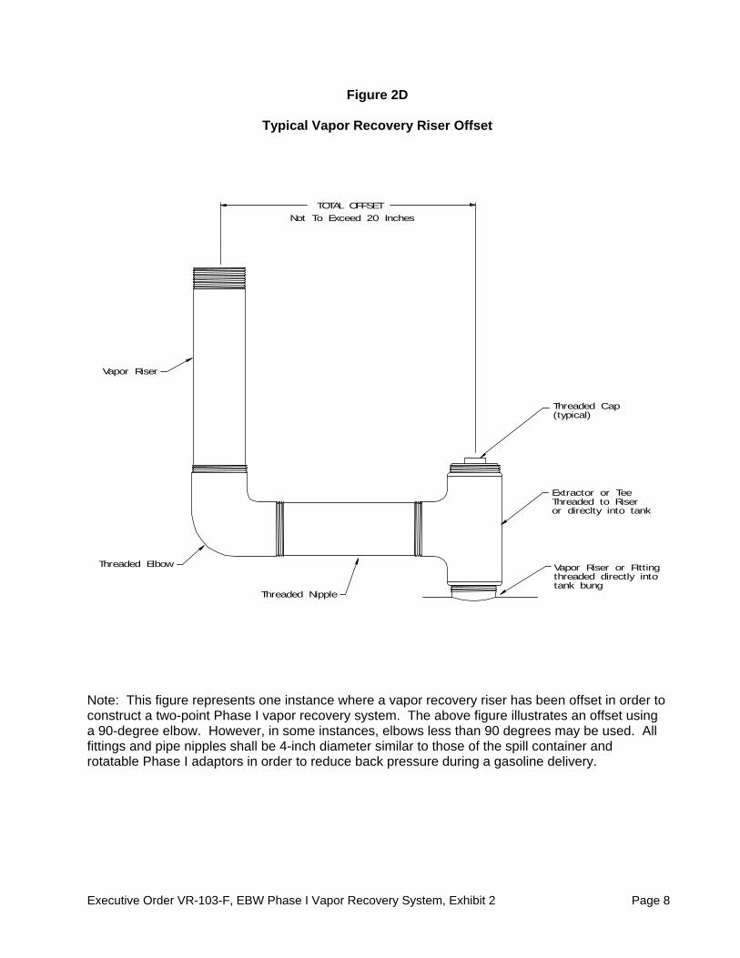
Vapor Recovery Riser Offset 1. The vapor recovery tank riser may be offset from the tank connection to the vapor recovery
Spill Container provided that the maximum horizontal distance (offset distance) does not exceed twenty (20) inches. An example of an offset is shown in Figure 2D.
2. The vapor recovery riser shall be offset using commercially available, four (4) inch diameter
steel pipe fittings. Tank Gauge Port Components 1. The tank gauge adaptor and cap are paired. Connections and Fittings 1. All connections and fittings not specifically certified with an allowable leak rate shall not leak.
The absence of vapor leaks may be verified by the use of commercial liquid leak detection solution (LDS), or by bagging, when the vapor containment space of the underground storage tank is subjected to a non-zero gauge pressure. (Note: leak detection solution will detect leaks only when positive gauge pressure exists.)
Maintenance Records 1. Each GDF operator/owner shall keep records of maintenance performed at the facility.
Such record shall be maintained on site in accordance with district requirements or policies. The records shall include the maintenance or test date, repair date to correct test failure, maintenance or test performed, affiliation, telephone number and name of individual conducting maintenance or test. An example of a Phase I Maintenance Record is shown in Figure 2E.

Executive Order VR-103-F, EBW Phase I Vapor Recovery System, Exhibit 2 Page 4
Table 2-1 Gasoline Dispensing Facility Compliance Standards and Specifications
Component Test
Method Standard or Specification
Rotatable Phase I Adaptors TP-201.1B Minimum, 360-degree rotation Maximum, 108 pound-inch average static torque
Overfill Prevention Device TP-201.1D 0.17 CFH at 2.00 inches H2O
Spill Container Drain Valve TP-201.1C Or TP-201.1D
0.17 CFH at 2.00 inches H2O
P/V Valve1 TP-201.1E
Positive pressure setting: 2.5 to 6.0 inches H2O Negative Pressure setting: -6.0 to -10 inches H2O Positive Leak rate: 0.05 CFH at 2.0 inches H2O Negative Leak rate: 0.21 CFH at -4.0 inches H2O
Gasoline Dispensing Facility TP-201.3 As specified in TP-201.3 and/or CP-201
All connections and fittings certified without an allowable leak rate
Leak Detection
Solution or bagging
No leaks
Table 2-2
Maintenance Intervals for System Components2
Manufacturer Equipment Maintenance Interval Husky Pressure/Vacuum Vent Valve Annual FFS Pressure/Vacuum Vent Valve Annual EBW Tank Gauge Components Annual EBW Dust Caps (All Models) Annual EBW Drop Tube Annual Phil-Tite Rotatable Phase I Adaptors Annual EBW Spill Containers Annual EBW Drop Tube Overfill Prevention Valve Annual
1 Compliance determination is at the option of the district. 2 Maintenance must be conducted within the interval specified from the date of installation and at least within the
specified interval thereafter.

Executive Order VR-103-F, EBW Phase I Vapor Recovery System, Exhibit 2 Page 5
Figure 2A
Typical Product Installation Using EBW System
Executive Order VR-103-F, EBW Phase I Vapor Recovery System, Exhibit 2 Page 6
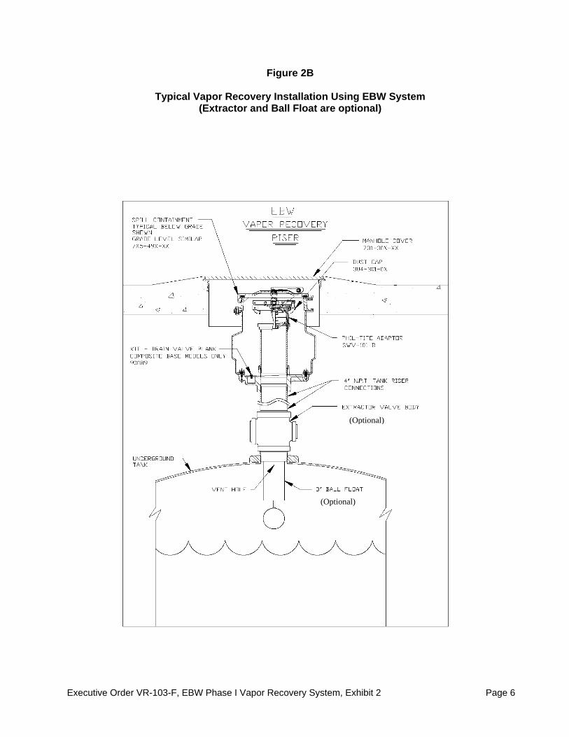
Figure 2B
Typical Vapor Recovery Installation Using EBW System (Extractor and Ball Float are optional)
(Optional)
(Optional)

Executive Order VR-103-F, EBW Phase I Vapor Recovery System, Exhibit 2 Page 7
Figure 2C
Typical Vent Pipe Manifold
Note: This shows only one typical configuration; other manifold configurations may be used. For example, a tee may be located in a different position, or fewer pipes may be connected, or more than one P/V valve may be installed on the manifold.
Executive Order VR-103-F, EBW Phase I Vapor Recovery System, Exhibit 2 Page 8
Figure 2D
Typical Vapor Recovery Riser Offset
Note: This figure represents one instance where a vapor recovery riser has been offset in order to construct a two-point Phase I vapor recovery system. The above figure illustrates an offset using a 90-degree elbow. However, in some instances, elbows less than 90 degrees may be used. All fittings and pipe nipples shall be 4-inch diameter similar to those of the spill container and rotatable Phase I adaptors in order to reduce back pressure during a gasoline delivery.
TOTAL OFFSET
Extractor or TeeThreaded to Riseror direclty into tank
Threaded Nipple
Threaded Elbow
Vapor Riser
Threaded Cap(typical)
Not To Exceed 20 Inches
Vapor Riser or FIttingthreaded directly intotank bung

Executive Order VR-103-F, EBW Phase I Vapor Recovery System, Exhibit 2 Page 9
Figure 2E
Example of a GDF Phase I Maintenance Record
Date of Maintenance/ Test/Inspection/Failure
Repair Date To Correct
Test Failure
Maintenance/Test/Inspection Performed and Outcome
Affiliation Name of Individual
Conducting Maintenance or Test
Telephone Number

Executive Order VR-103-F, EBW Phase I Vapor Recovery System, Exhibit 3 Page 1
Executive Order VR-103-F EBW Phase I Vapor Recovery System
Exhibit 3
Manufacturing Performance Standards and Specifications The EBW system and all components shall be manufactured in compliance with the performance standards and specifications in CP-201, as well as the requirements specified in this Executive Order. All components shall be manufactured as certified; no change to the equipment; parts, design, materials or manufacturing process shall be made unless approved in writing by the Executive Officer or Executive Officer delegate. Unless specified in Exhibit 2 or in the ARB Approved Installation, Operation and Maintenance Manual for the EBW Phase I Vapor Recovery System, the requirements of this section apply only to the manufacturing process and are not appropriate for determining the compliance status of a GDF. Pressure/Vacuum Vent Valves for Storage Tank Vent Pipes 1. Each Pressure/Vacuum Vent Valve (P/V valve) shall be tested at the factory for cracking
pressure and leak rate at each specified pressure setting and shall be done in accordance with TP-201.1E, Leak Rate and Cracking Pressure of Pressure/Vacuum Vent Valves (October 8, 2003).
2. Each P/V valve shall be shipped with a card or label stating the performance
specifications listed in Table 3-1, and a statement that the valve was tested to, and met, these specifications.
3. Each P/V valve shall have permanently affixed to it a yellow or gold label with black
lettering listing the positive and negative pressure settings and leak rate standards listed in Table 3-1. The lettering of the positive and negative pressure settings and leak rate standards on the label shall have a minimum font size of 20.
Rotatable Product and Vapor Recovery Adaptors 1. The rotatable product and vapor recovery adaptors shall not leak. 2. The product adaptor cam and groove shall be manufactured in accordance with the cam
and groove specifications shown in Figure 3A of CP-201. 3. The vapor recovery adaptor cam and groove shall be manufactured in accordance with the
cam and groove specifications shown in Figure 3B of CP-201. 4. Each product and vapor recovery adaptor shall be tested at the factory to, and met, the
specifications listed in Table 3-1 and shall have affixed to it a card or label listing these performance specifications and a statement that the adaptor was tested to, and met, such specifications.
Spill Container and Drain Valves 1. Each Spill Container Drain Valve shall be tested at the factory to, and met, the
specifications listed in Table 3-1 and shall have affixed to it a card or label listing the

Executive Order VR-103-F, EBW Phase I Vapor Recovery System, Exhibit 3 Page 2
performance specification and a statement that the valve was tested to, and met, such performance specification.
Drop Tube Overfill Prevention Device 1. Each Drop Tube Overfill Prevention Device shall be tested at the factory to, and met, the
specification listed in Table 3-1 and shall have affixed to it a card or label listing the performance specification and a statement that the device was tested to, and met, such performance specification.
Table 3-1
Manufacturing Component Standards and Specifications
Component Test
Method Standard or Specification
Rotatable Phase I Adaptors TP-201.1B Minimum 360-degree rotation
Maximum 108 lb-inch average static torque
Rotatable Phase I Adaptors Micrometer Cam and Groove Specifications (CP-201)
Spill Container Drain Valve TP-201.1C
or TP-201.1D 0.17 CFH at 2.00 inches H2O
Overfill Prevention Device TP-201.1D 0.17 CFH at 2.00 inches H2O
Pressure/Vacuum Vent Valve
TP-201.1E
Positive Pressure: 2.5 to 6 inches H2O
Negative Pressure: -6 to -10 inches H2O
Leak rate: 0.05 CFH at +2.0 inches H2O
0.21 CFH at -4.0 inches H2O